installation & operating guide exgp oxygen analyzer … · exgp oxygen analyzer system (atex)...
TRANSCRIPT

EXGP Oxygen Analyzer System (ATEX)
Oxygen Transmitters –4680 & 4685
Installation & Operating GuideIM/EXGP–4600_5
ABB
The Company
We are an established world force in the design and manufacture of instrumentation for industrialprocess control, flow measurement, gas and liquid analysis and environmental applications.
As a part of ABB, a world leader in process automation technology, we offer customersapplication expertise, service and support worldwide.
We are committed to teamwork, high quality manufacturing, advanced technology and unrivalledservice and support.
The quality, accuracy and performance of the Company’s products result from over 100 yearsexperience, combined with a continuous program of innovative design and development toincorporate the latest technology.
The NAMAS Calibration Laboratory No. 0255 is just one of the ten flow calibration plantsoperated by the Company, and is indicative of our dedication to qualityand accuracy.
Electrical Safety
This equipment complies with the requirements of CEI/IEC 61010-1:2001-2 'Safety Requirements for Electrical Equipment forMeasurement, Control and Laboratory Use'. If the equipment is used in a manner NOT specified by the Company, the protectionprovided by the equipment may be impaired.
Symbols
One or more of the following symbols may appear on the equipment labelling:
Health and SafetyTo ensure that our products are safe and without risk to health, the following points must be noted:
1. The relevant sections of these instructions must be read carefully before proceeding.
2. Warning labels on containers and packages must be observed.
3. Installation, operation, maintenance and servicing must only be carried out by suitably trained personnel and in accordance with theinformation given.
4. Normal safety precautions must be taken to avoid the possibility of an accident occurring when operating in conditions of high pressure and/or temperature.
5. Chemicals must be stored away from heat, protected from temperature extremes and powders kept dry. Normal safe handling proceduresmust be used.
6. When disposing of chemicals ensure that no two chemicals are mixed.
Safety advice concerning the use of the equipment described in this manual or any relevant hazard data sheets (where applicable) may beobtained from the Company address on the back cover, together with servicing and spares information.
Warning – Refer to the manual for instructions
Caution – Risk of electric shock
Protective earth (ground) terminal
Earth (ground) terminal
Direct current supply only
Alternating current supply only
Both direct and alternating current supply
The equipment is protectedthrough double insulation
Information in this manual is intended only to assist our customers in the efficient operation of our equipment. Use of this manual forany other purpose is specifically prohibited and its contents are not to be reproduced in full or part without prior approval of theTechnical Publications Department.
EN ISO 9001:1994
Cert. No. Q05907
EN 29001 (ISO 9001)
Lenno, Italy – Cert. No. 9/90A
0255
Stonehouse, U.K.
1
CONTENTS 1 INTRODUCTION
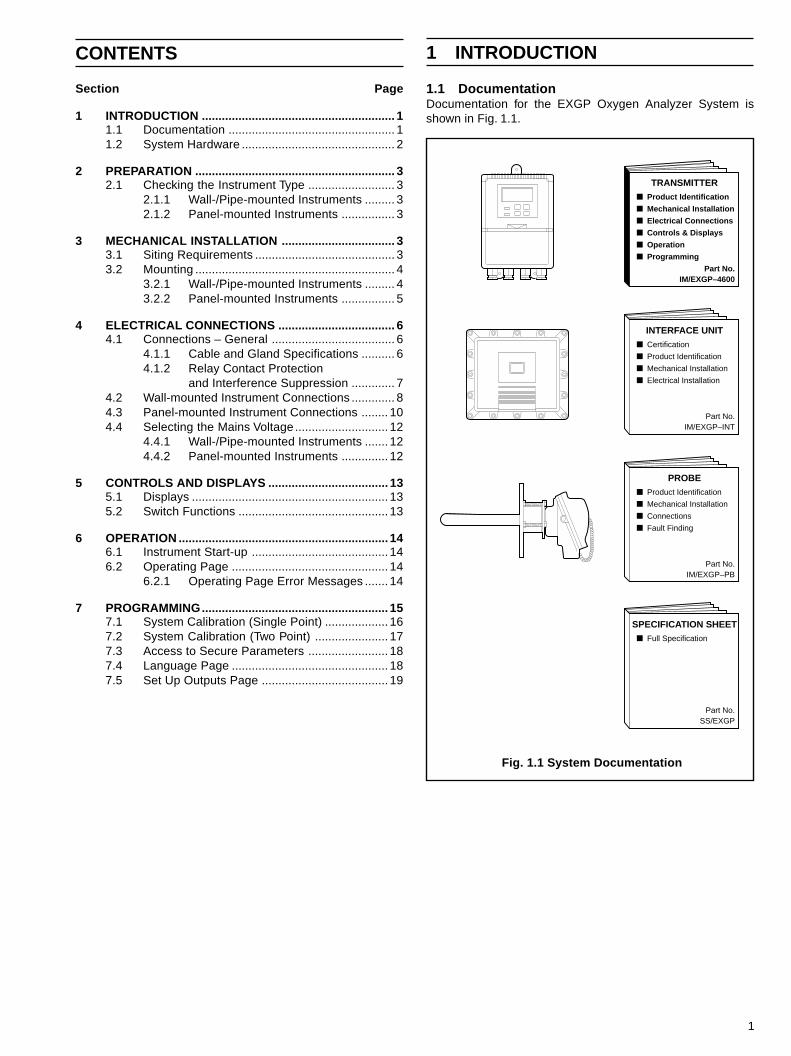
1.1 DocumentationDocumentation for the EXGP Oxygen Analyzer System isshown in Fig. 1.1.
Fig. 1.1 System Documentation
TRANSMITTERProduct Identification
Mechanical Installation
Electrical Connections
Controls & Displays
Operation
Programming
■
■
■
■
■
■
Part No.IM/EXGP–4600
INTERFACE UNITCertification
Product Identification
Mechanical Installation
Electrical Installation
■
■
■
■
Part No.IM/EXGP–INT
PROBE■
■
■
■
Part No.IM/EXGP–PB
SPECIFICATION SHEETFull Specification■
Part No.SS/EXGP
Product Identification
Mechanical Installation
Connections
Fault Finding
Section Page
1 INTRODUCTION .......................................................... 11.1 Documentation .................................................. 11.2 System Hardware .............................................. 2
2 PREPARATION ............................................................ 32.1 Checking the Instrument Type .......................... 3
2.1.1 Wall-/Pipe-mounted Instruments ......... 32.1.2 Panel-mounted Instruments ................ 3
3 MECHANICAL INSTALLATION .................................. 33.1 Siting Requirements .......................................... 33.2 Mounting ............................................................ 4
3.2.1 Wall-/Pipe-mounted Instruments ......... 43.2.2 Panel-mounted Instruments ................ 5
4 ELECTRICAL CONNECTIONS ................................... 64.1 Connections – General ..................................... 6
4.1.1 Cable and Gland Specifications .......... 64.1.2 Relay Contact Protection
and Interference Suppression ............. 74.2 Wall-mounted Instrument Connections ............. 84.3 Panel-mounted Instrument Connections ........ 104.4 Selecting the Mains Voltage ............................ 12
4.4.1 Wall-/Pipe-mounted Instruments ....... 124.4.2 Panel-mounted Instruments .............. 12
5 CONTROLS AND DISPLAYS .................................... 135.1 Displays ........................................................... 135.2 Switch Functions ............................................. 13
6 OPERATION ............................................................... 146.1 Instrument Start-up ......................................... 146.2 Operating Page ............................................... 14
6.2.1 Operating Page Error Messages ....... 14
7 PROGRAMMING........................................................ 157.1 System Calibration (Single Point) ................... 167.2 System Calibration (Two Point) ...................... 177.3 Access to Secure Parameters ........................ 187.4 Language Page ............................................... 187.5 Set Up Outputs Page ...................................... 19
2
…1 INTRODUCTION
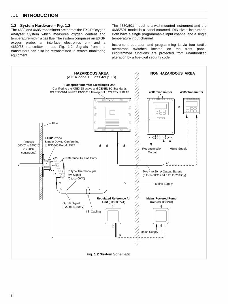
1.2 System Hardware – Fig. 1.2The 4680 and 4685 transmitters are part of the EXGP OxygenAnalyzer System which measures oxygen content andtemperature within a gas flue. The system comprises an EXGPoxygen probe, an interface electronics unit and a4680/85 transmitter – see Fig. 1.2. Signals from thetransmitters can also be retransmitted to remote monitoringequipment.
The 4680/501 model is a wall-mounted instrument and the4685/501 model is a panel-mounted, DIN-sized instrument.Both have a single programmable input channel and a singletemperature input channel.
Instrument operation and programming is via four tactilemembrane switches located on the front panel.Programmed functions are protected from unauthorizedalteration by a five-digit security code.
Mains Powered PumpUnit (003000240)
NON HAZARDOUS AREAHAZARDOUS AREA(ATEX Zone 1, Gas Group IIB)
Process600°C to 1400°C
(1250°Ccontinuous)
EXGP ProbeSimple Device Conformingto BS5345 Part 4: 1977
Mains Supply
R Type ThermocouplemV Signal(0 to 1400°C)
Two 4 to 20mA Output Signals(0 to 1400°C and 0.25 to 25%O2)
or
4680 Transmitter
Mains Supply
Flameproof Interface Electronics UnitCertified to the ATEX Directive and CENELEC Standards
BS EN50014 and BS EN50018 flameproof II 2G EEx d IIB T6
Flue
4685 Transmitter
RetransmissionOutput
Reference Air Line Entry
Regulated Reference AirUnit (003000241)
Mains Supply
O2 mV Signal(–20 to +180mV)
or
or
I.S. Cabling
Fig. 1.2 System Schematic
3
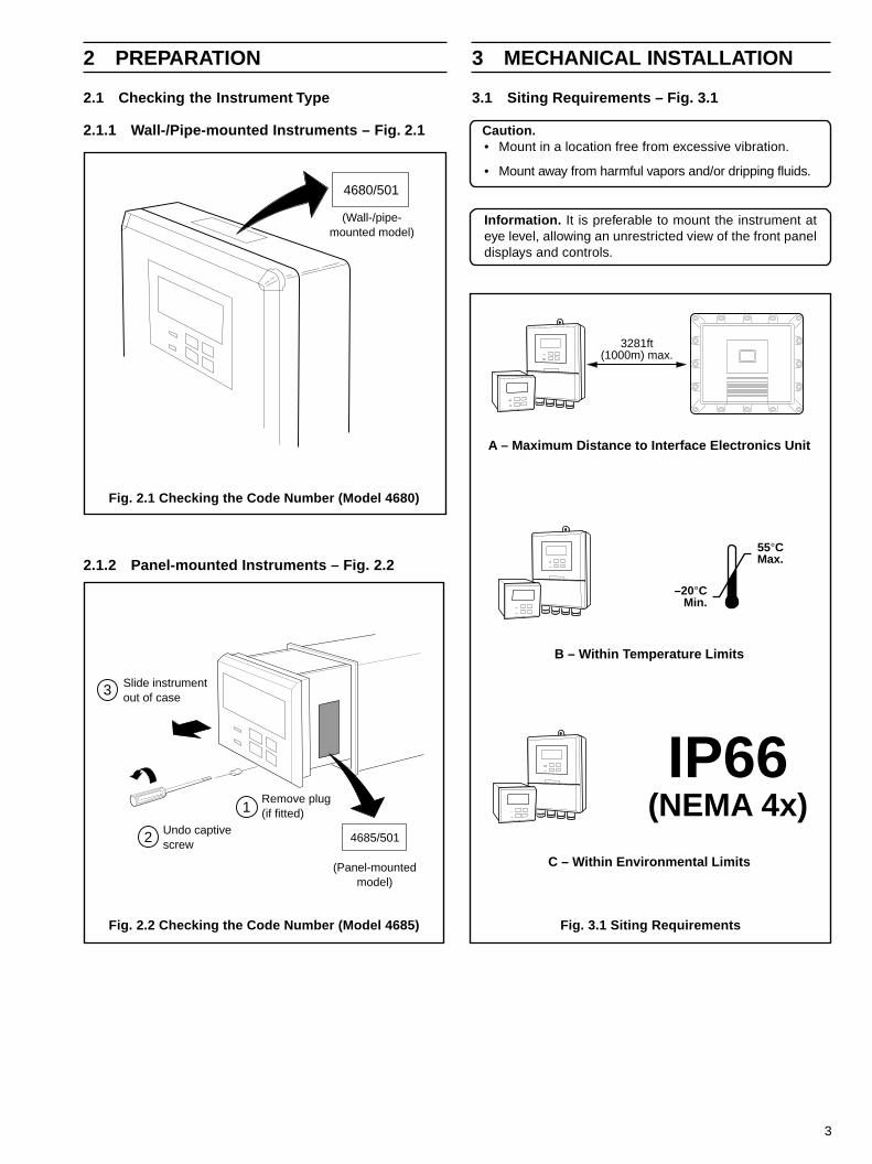
2.1 Checking the Instrument Type
2.1.1 Wall-/Pipe-mounted Instruments – Fig. 2.1
2 PREPARATION 3 MECHANICAL INSTALLATION
2.1.2 Panel-mounted Instruments – Fig. 2.2
3.1 Siting Requirements – Fig. 3.1
Caution.• Mount in a location free from excessive vibration.
• Mount away from harmful vapors and/or dripping fluids.
Information. It is preferable to mount the instrument ateye level, allowing an unrestricted view of the front paneldisplays and controls.
C – Within Environmental Limits
B – Within Temperature Limits
A – Maximum Distance to Interface Electronics Unit
3281ft(1000m) max.
55°CMax.
–20°CMin.
IP66(NEMA 4x)
Slide instrumentout of case
(Panel-mountedmodel)
4685/501Undo captivescrew
Remove plug(if fitted)1
2
3
4680/501
(Wall-/pipe-mounted model)
Fig. 2.1 Checking the Code Number (Model 4680)
Fig. 2.2 Checking the Code Number (Model 4685) Fig. 3.1 Siting Requirements
4
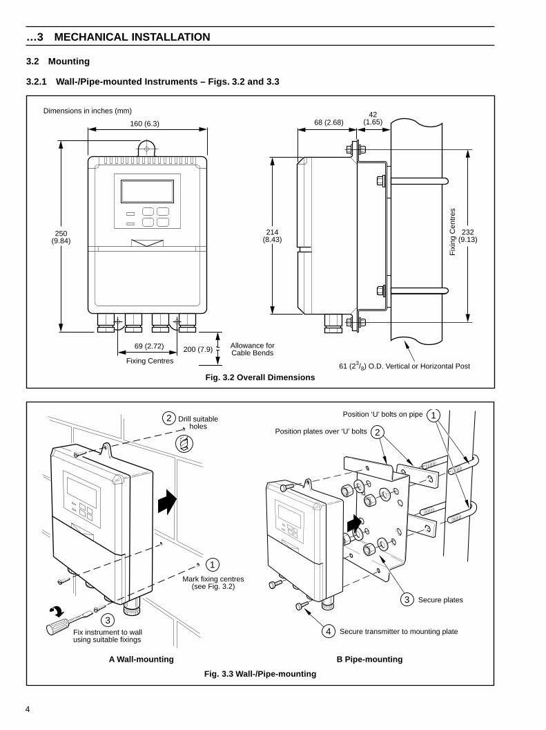
3.2 Mounting
3.2.1 Wall-/Pipe-mounted Instruments – Figs. 3.2 and 3.3
…3 MECHANICAL INSTALLATION
Position ‘U’ bolts on pipe
Position plates over ‘U’ bolts
Secure transmitter to mounting plate
Secure plates
1
2
3
4
Mark fixing centres(see Fig. 3.2)
Drill suitableholes
Fix instrument to wallusing suitable fixings
1
2
3
A Wall-mounting B Pipe-mounting
68 (2.68)
214(8.43)
232(9.13)
Fix
ing
Cen
tres
160 (6.3)
250(9.84)
69 (2.72)
Fixing Centres
Allowance forCable Bends200 (7.9)
42(1.65)
61 (23/8) O.D. Vertical or Horizontal Post
Dimensions in inches (mm)
Fig. 3.2 Overall Dimensions
Fig. 3.3 Wall-/Pipe-mounting
5
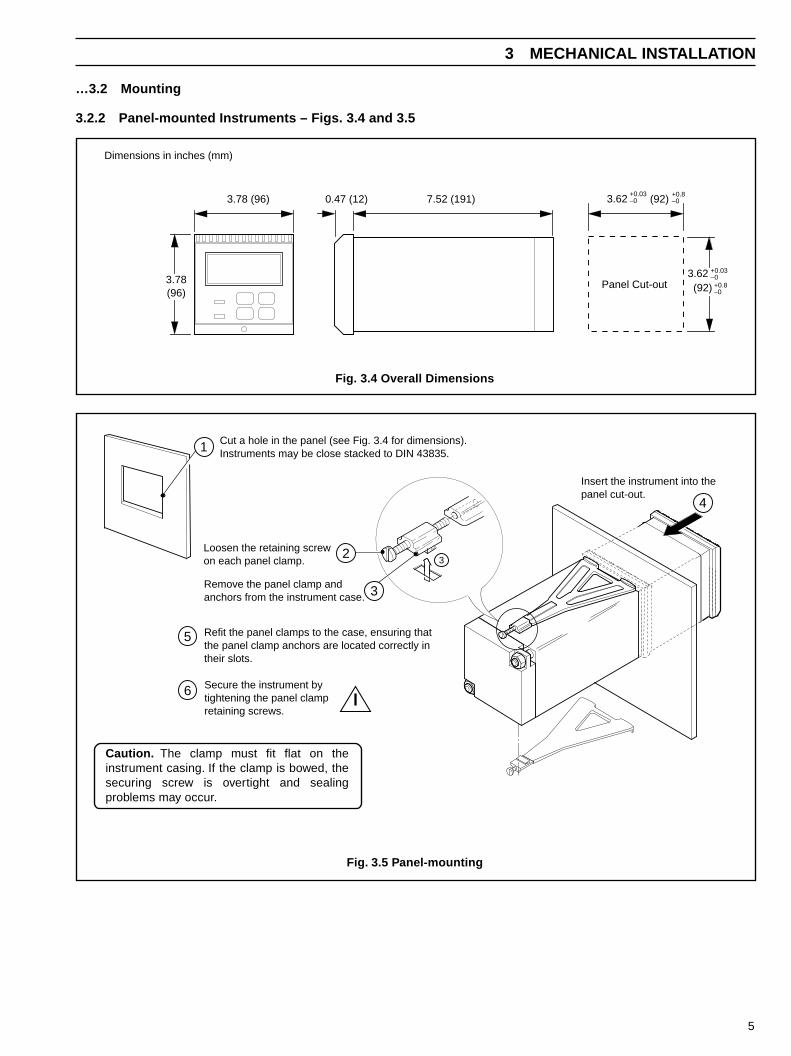
…3.2 Mounting
3.2.2 Panel-mounted Instruments – Figs. 3.4 and 3.5
3 MECHANICAL INSTALLATION
7.52 (191)0.47 (12)
Panel Cut-out
3.78 (96)
3.78(96)
+0.8–0(92)
3.62+0.03–0
+0.8–0(92)
3.62 +0.03–0
Dimensions in inches (mm)
Cut a hole in the panel (see Fig. 3.4 for dimensions).Instruments may be close stacked to DIN 43835.
Insert the instrument into thepanel cut-out.
Refit the panel clamps to the case, ensuring thatthe panel clamp anchors are located correctly intheir slots.
Secure the instrument bytightening the panel clampretaining screws.
Loosen the retaining screwon each panel clamp.
Remove the panel clamp andanchors from the instrument case.
1
2
3
4
5
6
3
Fig. 3.4 Overall Dimensions
Fig. 3.5 Panel-mounting
Caution. The clamp must fit flat on theinstrument casing. If the clamp is bowed, thesecuring screw is overtight and sealingproblems may occur.
6
ecafretnI–noitacificepSdnalG )slangiSdxEE(noitacificepSelbaC rettimsnarT–noitacificepSdnalG
dxEEdeifitrecfoorpemalf02M)deilppuston(dnalgreirrab
slangiStuptuO)Am(noissimsnarteR:)erutarepmeTdnanegyxO(
.foorpemalf,neercsllarevo,reppocPT2eroc-4,2.0/61)deilppustoN(
057ecnatsiserpoolxam:BN
)dettif(deifitrecnU02M:0864deriuqerdnalgoN:5864
dxEEdeifitrecfoorpemalf02M)deilppuston(dnalgreirrab
:ylppuSrewoPsniaM).nim(reppocmm5.0,eroc-3
)deilppustoN(
)dettif(deifitrecnU02M:0864deriuqerdnalgoN:5864
4 ELECTRICAL CONNECTIONS
Warning.• Mains power – before making any connections, ensure that the power supply, any high voltage-operated control circuits
and high common mode voltages are switched off.
4.1 Connections – General
Information.• Earthing (grounding) – stud terminal(s) is fitted to the transmitter case for bus-bar earth (ground) connection – see Fig. 4.2 or 4.5.
• Cable routing – always route signal output cable leads and mains-carrying/relay cables separately, ideally in earthed metalconduit. Twist the signal output leads together or use screened cable with the screen connected to the case earth stud.
Ensure that the cables enter the transmitter through the glands nearest the appropriate screw terminals and are short anddirect. Do not tuck excess cable into the terminal compartment.
• Relays –the relay contacts are voltage-free and must be appropriately connected in series with the power supply and thealarm/control device which they are to actuate. Ensure that the contact rating is not exceeded. Refer also to Section 4.1.2for relay contact protection details when the relays are to be used for switching loads.
• Retransmission output – Do not exceed the maximum load specification for the selected current retransmission range(see the associated Specification sheet).
Since the retransmission output is isolated the –ve terminal must be connected to earth (ground) if connecting to theisolated input of another device.
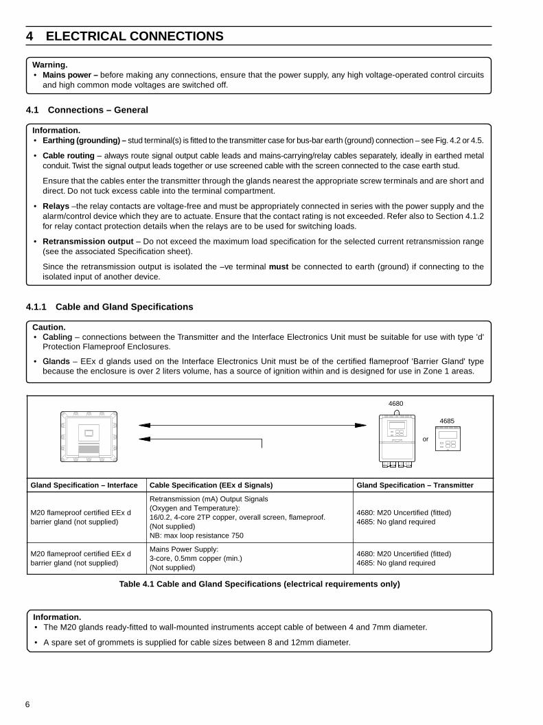
4.1.1 Cable and Gland Specifications
Caution.• Cabling – connections between the Transmitter and the Interface Electronics Unit must be suitable for use with type 'd'
Protection Flameproof Enclosures.
• Glands – EEx d glands used on the Interface Electronics Unit must be of the certified flameproof 'Barrier Gland' typebecause the enclosure is over 2 liters volume, has a source of ignition within and is designed for use in Zone 1 areas.
Information.• The M20 glands ready-fitted to wall-mounted instruments accept cable of between 4 and 7mm diameter.
• A spare set of grommets is supplied for cable sizes between 8 and 12mm diameter.
4685
4680
or
Table 4.1 Cable and Gland Specifications (electrical requirements only)
7
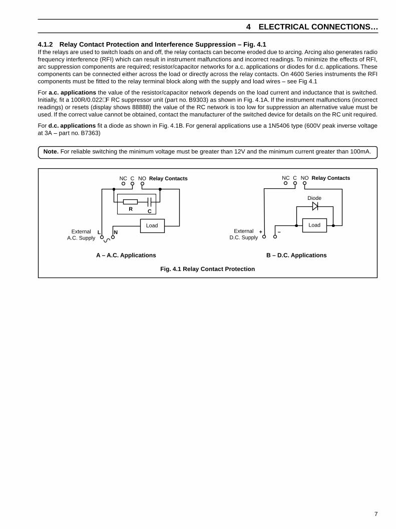
4 ELECTRICAL CONNECTIONS…
4.1.2 Relay Contact Protection and Interference Suppression – Fig. 4.1If the relays are used to switch loads on and off, the relay contacts can become eroded due to arcing. Arcing also generates radiofrequency interference (RFI) which can result in instrument malfunctions and incorrect readings. To minimize the effects of RFI,arc suppression components are required; resistor/capacitor networks for a.c. applications or diodes for d.c. applications. Thesecomponents can be connected either across the load or directly across the relay contacts. On 4600 Series instruments the RFIcomponents must be fitted to the relay terminal block along with the supply and load wires – see Fig 4.1
For a.c. applications the value of the resistor/capacitor network depends on the load current and inductance that is switched.Initially, fit a 100R/0.022µF RC suppressor unit (part no. B9303) as shown in Fig. 4.1A. If the instrument malfunctions (incorrectreadings) or resets (display shows 88888) the value of the RC network is too low for suppression an alternative value must beused. If the correct value cannot be obtained, contact the manufacturer of the switched device for details on the RC unit required.
For d.c. applications fit a diode as shown in Fig. 4.1B. For general applications use a 1N5406 type (600V peak inverse voltageat 3A – part no. B7363)
Note. For reliable switching the minimum voltage must be greater than 12V and the minimum current greater than 100mA.
NC C NO
ExternalA.C. Supply
L N
Relay Contacts
CR
Load
NC C NO
ExternalD.C. Supply
+ –
Relay Contacts
Load
Diode
A – A.C. Applications B – D.C. Applications
Fig. 4.1 Relay Contact Protection
8
…4 ELECTRICAL CONNECTIONS
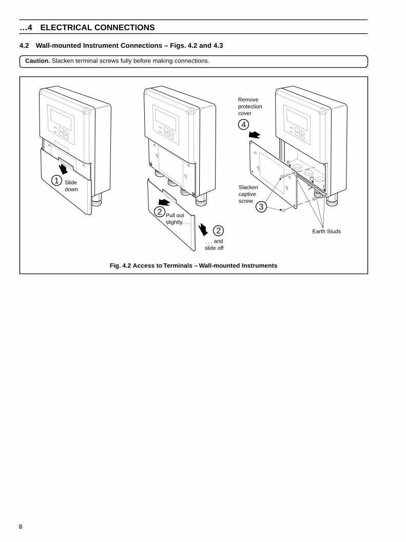
4.2 Wall-mounted Instrument Connections – Figs. 4.2 and 4.3
Caution. Slacken terminal screws fully before making connections.
Earth Studs
Slidedown
Pull outslightly. . .
. . . andslide off
Removeprotectioncover
Slackencaptivescrew
1
32
4
2
Fig. 4.2 Access to Terminals – Wall-mounted Instruments
9
4 ELECTRICAL CONNECTIONS…
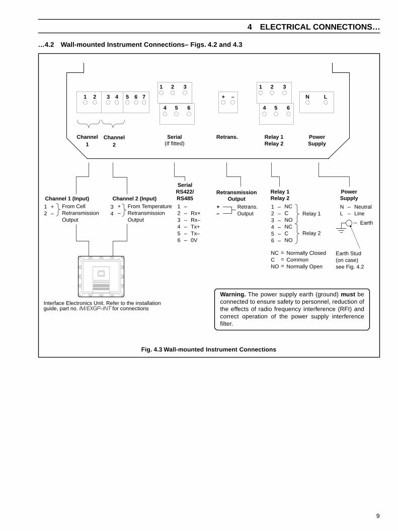
…4.2 Wall-mounted Instrument Connections– Figs. 4.2 and 4.3
Channel 1 (Input) Channel 2 (Input)PowerSupply
RetransmissionOutput
Relay 1Relay 2
SerialRS422/RS485
Channel1
Channel2
PowerSupply
Retrans. Relay 1Relay 2
1 2 3 4 5 6 7 + – N L
Serial(If fitted)
1 2 3
4 5 6
1 2 3
4 5 6
12
+–
From CellRetransmissionOutput
34
+–
123456
––––––
Rx+Rx–Tx+Tx–0V
+–
Retrans.Output
123456
––––––
NCCNONCCNO
Relay 1
Relay 2
NL
––
NeutralLine
– Earth
Earth Stud(on case)see Fig. 4.2
NCCNO
Normally ClosedCommonNormally Open
===
From TemperatureRetransmissionOutput
Interface Electronics Unit. Refer to the installationguide, part no. IM/EXGP–INT for connections
Warning. The power supply earth (ground) must beconnected to ensure safety to personnel, reduction ofthe effects of radio frequency interference (RFI) andcorrect operation of the power supply interferencefilter.
Fig. 4.3 Wall-mounted Instrument Connections
10
…4 ELECTRICAL CONNECTIONS
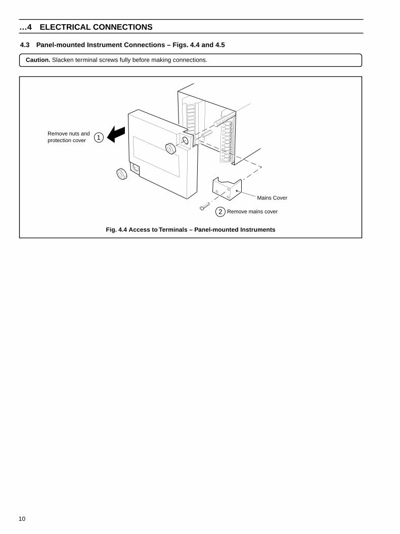
4.3 Panel-mounted Instrument Connections – Figs. 4.4 and 4.5
Caution. Slacken terminal screws fully before making connections.
Remove nuts andprotection cover
Remove mains cover
Mains Cover
1
2
Fig. 4.4 Access to Terminals – Panel-mounted Instruments
11
4 ELECTRICAL CONNECTIONS…
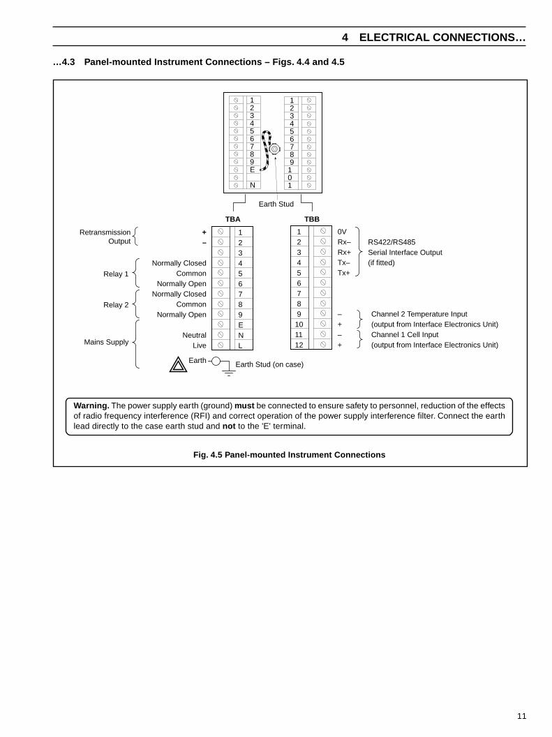
…4.3 Panel-mounted Instrument Connections – Figs. 4.4 and 4.5
+–
Normally ClosedCommon
Normally OpenNormally Closed
CommonNormally Open
NeutralLive
Earth
Relay 1
Relay 2
123456789ENL
1 2 3 4 5 6 7 8 9101112Mains Supply
RetransmissionOutput
0VRx–Rx+Tx–Tx+
– Channel 2 Temperature Input+ (output from Interface Electronics Unit)– Channel 1 Cell Input+ (output from Interface Electronics Unit)
RS422/RS485Serial Interface Output(if fitted)
Earth Stud (on case)
TBA TBB
Earth Stud
123456789E
N
1 2 3 4 5 6 7 8 9101
Warning. The power supply earth (ground) must be connected to ensure safety to personnel, reduction of the effectsof radio frequency interference (RFI) and correct operation of the power supply interference filter. Connect the earthlead directly to the case earth stud and not to the 'E' terminal.
Fig. 4.5 Panel-mounted Instrument Connections
12
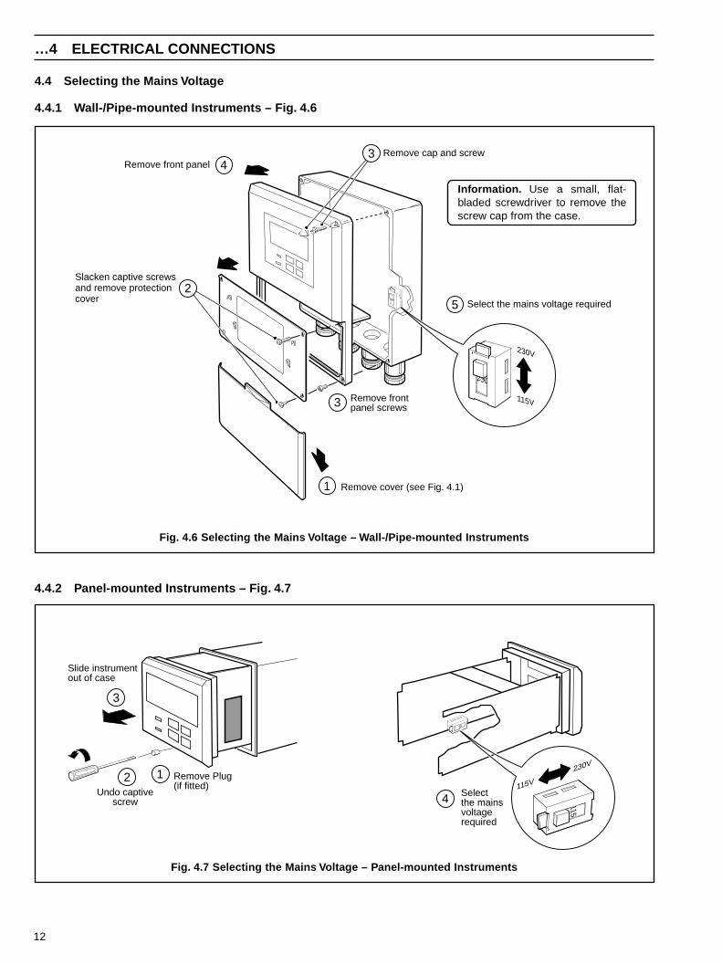
4.4 Selecting the Mains Voltage
4.4.1 Wall-/Pipe-mounted Instruments – Fig. 4.6
…4 ELECTRICAL CONNECTIONS
4.4.2 Panel-mounted Instruments – Fig. 4.7
230
Remove cover (see Fig. 4.1)
Slacken captive screwsand remove protectioncover
Remove frontpanel screws
Remove front panel
Select the mains voltage required
Remove cap and screw
230
230V
115V
1
2
34
5
3
Selectthe mainsvoltagerequired
115
115
115V
230V
115
4
Slide instrumentout of case
Undo captivescrew
Remove Plug(if fitted)
12
3
Fig. 4.6 Selecting the Mains Voltage – Wall-/Pipe-mounted Instruments
Information. Use a small, flat-bladed screwdriver to remove thescrew cap from the case.
Fig. 4.7 Selecting the Mains Voltage – Panel-mounted Instruments
13
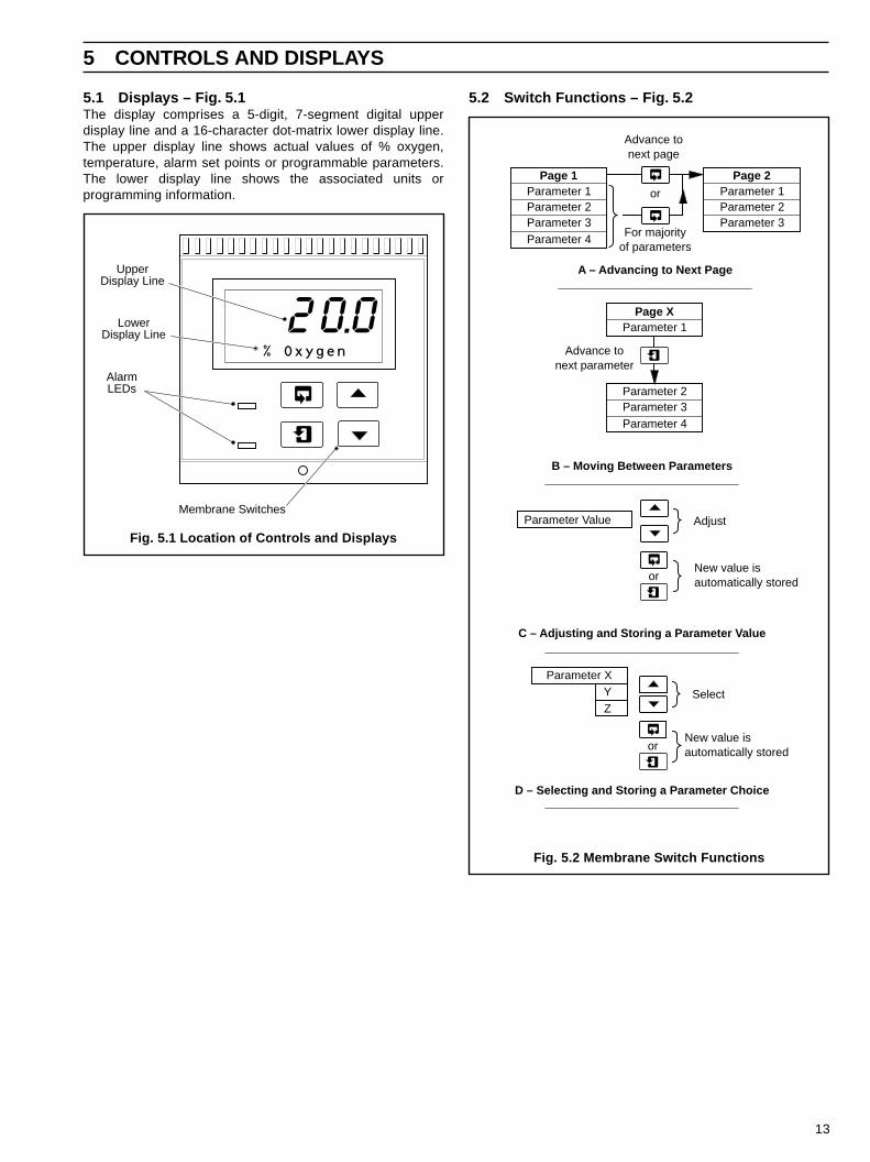
5.1 Displays – Fig. 5.1The display comprises a 5-digit, 7-segment digital upperdisplay line and a 16-character dot-matrix lower display line.The upper display line shows actual values of % oxygen,temperature, alarm set points or programmable parameters.The lower display line shows the associated units orprogramming information.
5 CONTROLS AND DISPLAYS
5.2 Switch Functions – Fig. 5.2
% Oxygen
AlarmLEDs
UpperDisplay Line
LowerDisplay Line
Membrane Switches
20.0A – Advancing to Next Page
B – Moving Between Parameters
C – Adjusting and Storing a Parameter Value
D – Selecting and Storing a Parameter Choice
New value isautomatically stored
Parameter 1Parameter 2Parameter 3Parameter 4
Page 1Parameter 1Parameter 2Parameter 3
Page 2
Advance tonext page
For majorityof parameters
or
Parameter 1
Parameter 2Parameter 3
Page X
Parameter 4
Advance tonext parameter
New value isautomatically stored
Parameter Value Adjust
or
Parameter XYZ
Select
or
Fig. 5.1 Location of Controls and Displays
Fig. 5.2 Membrane Switch Functions
14
6 OPERATION
6.1 Instrument Start-upEnsure all electrical connections have been made correctly and switch on.
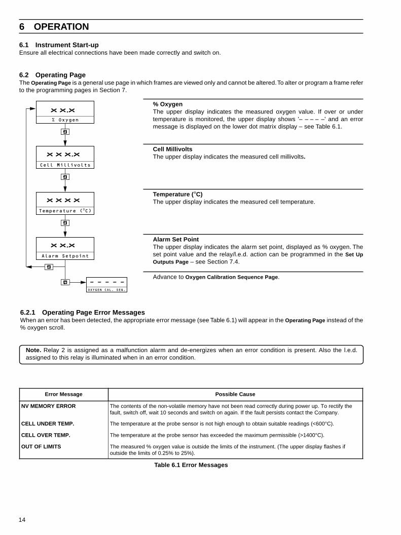
6.2 Operating PageThe Operating Page is a general use page in which frames are viewed only and cannot be altered. To alter or program a frame referto the programming pages in Section 7.
% OxygenThe upper display indicates the measured oxygen value. If over or undertemperature is monitored, the upper display shows '– – – – –' and an errormessage is displayed on the lower dot matrix display – see Table 6.1.
Cell MillivoltsThe upper display indicates the measured cell millivolts.
Temperature (°C)The upper display indicates the measured cell temperature.
Alarm Set PointThe upper display indicates the alarm set point, displayed as % oxygen. Theset point value and the relay/l.e.d. action can be programmed in the Set UpOutputs Page – see Section 7.4.
Advance to Oxygen Calibration Sequence Page.
xx.x% Oxygen
Alarm Setpoint
Cell Millivolts
Temperature (0C)
OXYGEN CAL. SEQ.
-----
xxx.x
xxxx
xx.x
6.2.1 Operating Page Error MessagesWhen an error has been detected, the appropriate error message (see Table 6.1) will appear in the Operating Page instead of the% oxygen scroll.
Note. Relay 2 is assigned as a malfunction alarm and de-energizes when an error condition is present. Also the l.e.d.assigned to this relay is illuminated when in an error condition.
egasseMrorrE esuaCelbissoP
RORREYROMEMVN ehtyfitceroT.purewopgnirudyltcerrocdaerneebtonevahyromemelitalov-nonehtfostnetnocehT.ynapmoCehttcatnocstsisreptluafehtfI.niaganohctiwsdnasdnoces01tiaw,ffohctiws,tluaf
.PMETREDNULLEC 006<(sgnidaerelbatiusniatboothguonehgihtonsirosneseborpehttaerutarepmetehT ° .)C
.PMETREVOLLEC 0041>(elbissimrepmumixamehtdedeecxesahrosneseborpehttaerutarepmetehT ° .)C
STIMILFOTUO fisehsalfyalpsidreppuehT(.tnemurtsniehtfostimilehtedistuosieulavnegyxo%derusaemehT.)%52ot%52.0fostimilehtedistuo
Table 6.1 Error Messages
15
7 PROGRAMMING
xx.x
% Oxygen
Alarm Setpoint
Cell Millivolts
Temperature (0C)
Ope
ratin
gP
aram
eter
s
Sec
ure
Par
amet
ers
OXYGEN CAL. SEQ.
Span % of Theory
Cal. User Code
One Point Cal.
Cell Constant mV
-----
00000
00000
SECURITY CODE
-----
SET UP OUTPUTS
5.0
Alarm Setpoint
-----
Alarm Action EB
-----
RTX Type 4-20
-----
LOG Output Yes
25.00
Retrans. Span
0.25
Retrans. Zero
––––
Hold Outputs Yes
No
0.0
Test Retrans (%)
00000
Alter Sec. Code
00000
Alter Cal. Code
-----
xxx.x
xxxx
xx.x
x.x
xxx.x
ELECTRICAL CAL
mA Zero 1 (4mA)
mA Span 1 (20mA)
mA Zero 2 (4mA)
Calibrate YES
mA Span 2 (20mA)
Adjust RTX Span
Adjust RTX Zero
-----
-----
xxxxx
xxxxx
xxxxx
xxxxx
-----
-----
NO
0-20
0-20
No
EA
Sec
tion
6.2,
Pag
e 14
Sec
tion
7.1,
Pag
e 16
or
Sec
tion
7.2,
Pag
e 17
Sec
tion
7.3,
Pag
e 18
Sec
tion
7.5,
Pag
e 19
For
full
calib
ratio
nde
tails
ref
er to
the
Ele
ctric
al C
alib
ratio
nS
uppl
emen
t
Connect to Air
Calibration Pass
Calibrating Air
20.95
20.95
Two Point Cal.
Connect to Air
Cal. Message
Calibrating Air
20.95
20.95
Enter Span Gas
Connect Span Gas
Calibrating Span
-----
-----
xx.xx
xx.xx
xx.xx
-----
0-20
0-10
-----
Espanol
Sec
tion
7.4,
Pag
e 18
Francais
Deutsch
English
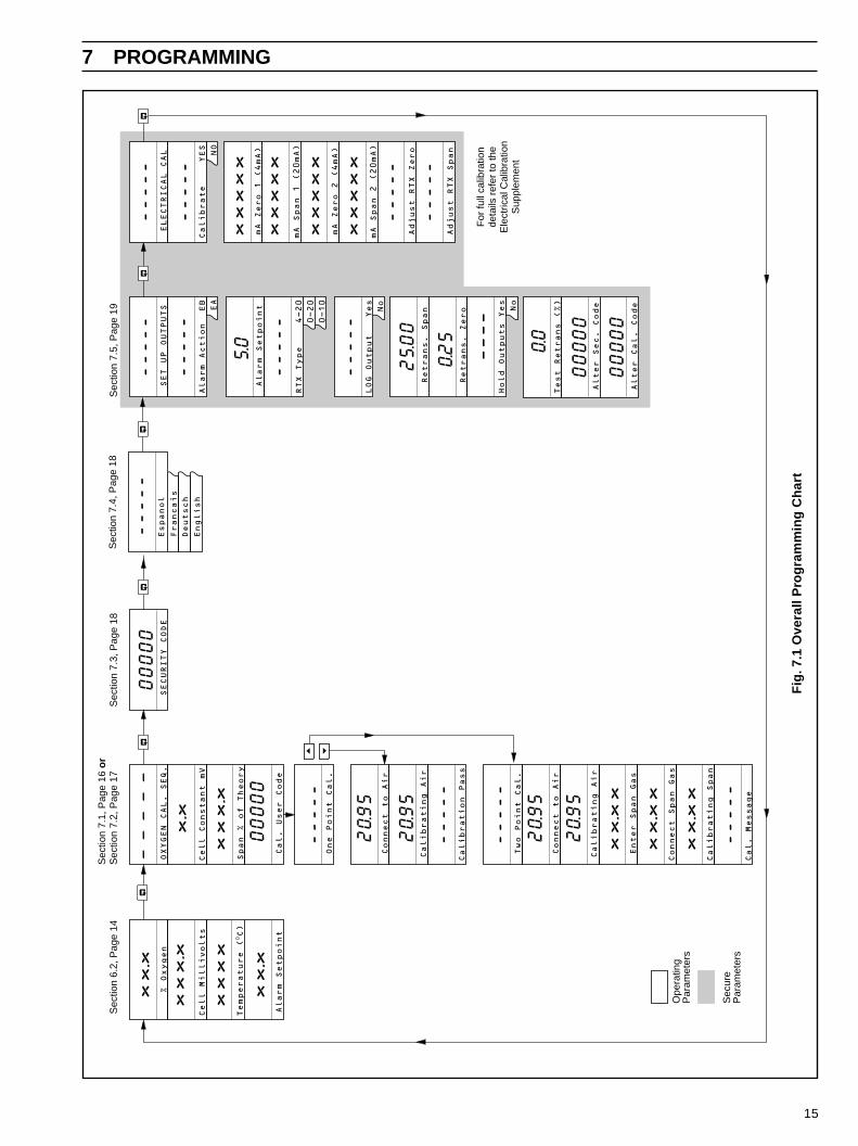
Fig
. 7.1
Ove
rall
Pro
gra
mm
ing
Ch
art
16
…7 PROGRAMMING
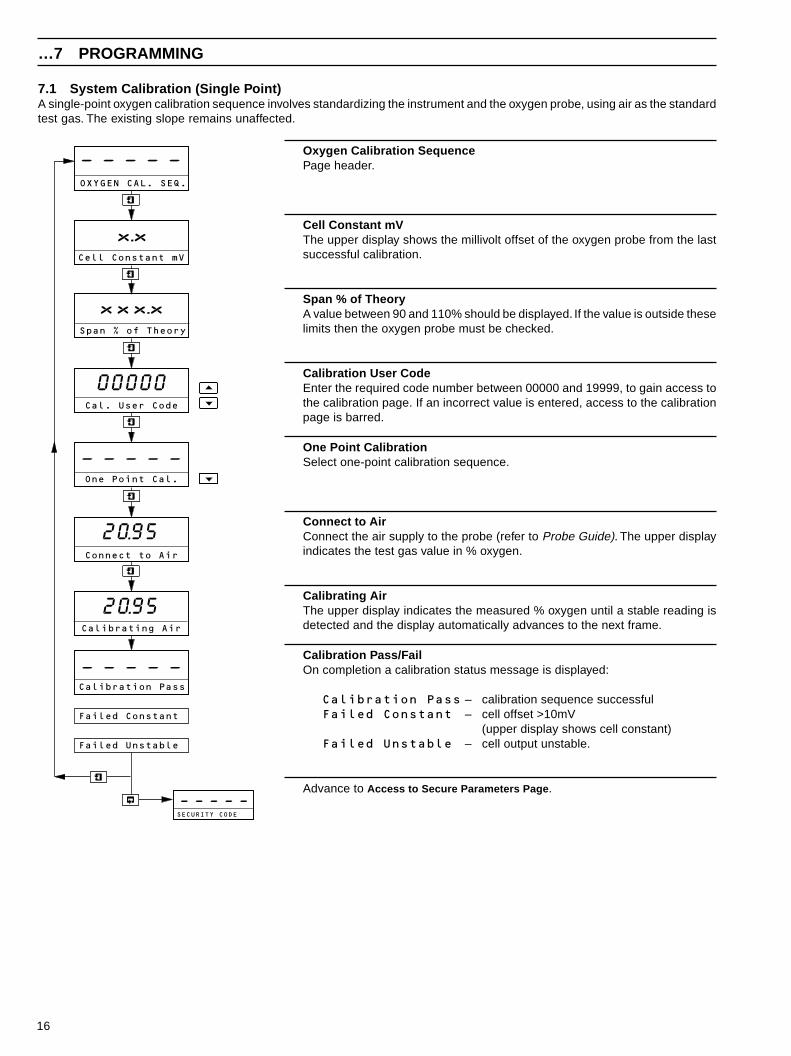
7.1 System Calibration (Single Point)A single-point oxygen calibration sequence involves standardizing the instrument and the oxygen probe, using air as the standardtest gas. The existing slope remains unaffected.
Oxygen Calibration SequencePage header.
Cell Constant mVThe upper display shows the millivolt offset of the oxygen probe from the lastsuccessful calibration.
Span % of TheoryA value between 90 and 110% should be displayed. If the value is outside theselimits then the oxygen probe must be checked.
Calibration User CodeEnter the required code number between 00000 and 19999, to gain access tothe calibration page. If an incorrect value is entered, access to the calibrationpage is barred.
One Point CalibrationSelect one-point calibration sequence.
Connect to AirConnect the air supply to the probe (refer to Probe Guide). The upper displayindicates the test gas value in % oxygen.
Calibrating AirThe upper display indicates the measured % oxygen until a stable reading isdetected and the display automatically advances to the next frame.
Calibration Pass/FailOn completion a calibration status message is displayed:
Calibration Pass – calibration sequence successfulFailed Constant – cell offset >10mV
(upper display shows cell constant)Failed Unstable – cell output unstable.
Advance to Access to Secure Parameters Page.
-----
OXYGEN CAL. SEQ.
Span % of Theory
Cal. User Code
One Point Cal.
SECURITY CODE
Cell Constant mV
Connect to Air
-----
-----
Calibrating Air
xxx.x
00000
x.x
-----
20.95
20.95
Failed Unstable
Failed Constant
Calibration Pass

17
7 PROGRAMMING…
7.2 System Calibration (Two Point)A two-point oxygen calibration sequence involves standardizing the instrument and the oxygen probe, using air as the zerostandard test gas and a known span test gas.
Oxygen Calibration SequencePage header.
Cell Constant mVThe upper display shows the millivolt offset of the oxygen probe from the lastsuccessful calibration.
Span % of TheoryA value between 90 and 110% should be displayed. If the value is outside theselimits then the oxygen probe must be checked.
Calibration User CodeEnter the required code number between 00000 and 19999, to gain access tothe calibration page. If an incorrect value is entered, the calibration pagecannot be accessed.
Two Point CalibrationSelect two-point calibration sequence.
Connect to AirConnect the air supply to the probe (refer to the Probe Guide). The upperdisplay indicates the test gas value in % oxygen.
Calibrating AirThe upper display indicates the measured % oxygen until a stable reading isdetected and the display advances automatically to the next frame.To abort calibration, press either the or switch to advance to the nextframe.
Enter Span GasEnter the value of the calibration span gas used (between 0.25 and 10.00% O2).
Connect Span GasConnect the span gas to the probe (refer to Probe Guide). The upper displayindicates the test gas value in % oxygen.
Calibrating SpanThe upper display indicates the measured % oxygen until a stable reading isdetected and the display automatically advances to the next frame.To abort calibration, press either the or switch to advance to the nextframe.
Continued on next page…
OXYGEN CAL. SEQ.
Cell Constant mV
-----
x.x
Span % of Theory
Cal. User Code
Two Point Cal.
Connect to Air
Calibrating Air
xxx.x
00000
-----
20.95
20.95
Connect Span Gas
Calibrating Span
xx.xx
xx.xx
Enter Span Gas
xx.xx
-----(Calibration Status)
18
…7 PROGRAMMING
…7.2 System Calibration (Two Point)
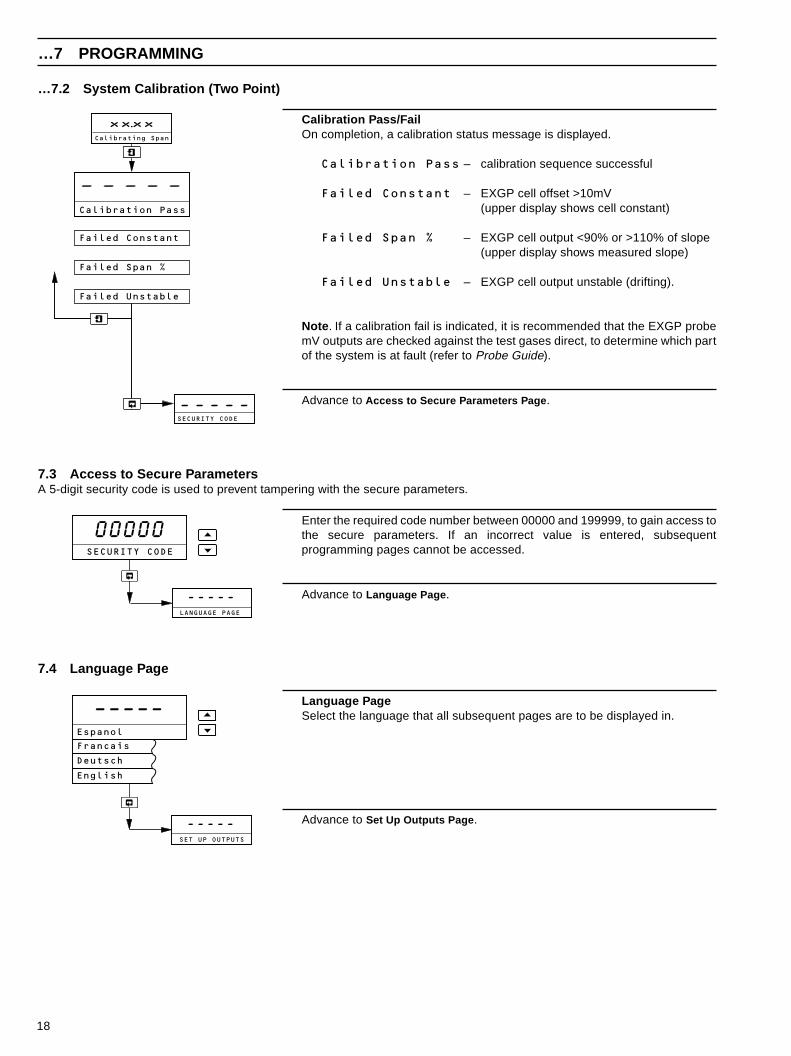
Calibration Pass/FailOn completion, a calibration status message is displayed.
Calibration Pass – calibration sequence successful
Failed Constant – EXGP cell offset >10mV(upper display shows cell constant)
Failed Span % – EXGP cell output <90% or >110% of slope(upper display shows measured slope)
Failed Unstable – EXGP cell output unstable (drifting).
Note. If a calibration fail is indicated, it is recommended that the EXGP probemV outputs are checked against the test gases direct, to determine which partof the system is at fault (refer to Probe Guide).
Advance to Access to Secure Parameters Page.
7.3 Access to Secure ParametersA 5-digit security code is used to prevent tampering with the secure parameters.
Calibrating Span
SECURITY CODE
-----
Failed Unstable
-----
Failed Constant
Failed Span %
Calibration Pass
xx.xx
Enter the required code number between 00000 and 199999, to gain access tothe secure parameters. If an incorrect value is entered, subsequentprogramming pages cannot be accessed.
Advance to Language Page.
00000SECURITY CODE
-----LANGUAGE PAGE
7.4 Language Page
–––––Espanol
-----SET UP OUTPUTS
Francais
Deutsch
English
Language PageSelect the language that all subsequent pages are to be displayed in.
Advance to Set Up Outputs Page.
19
7 PROGRAMMING…
7.5 Set Up Outputs Page
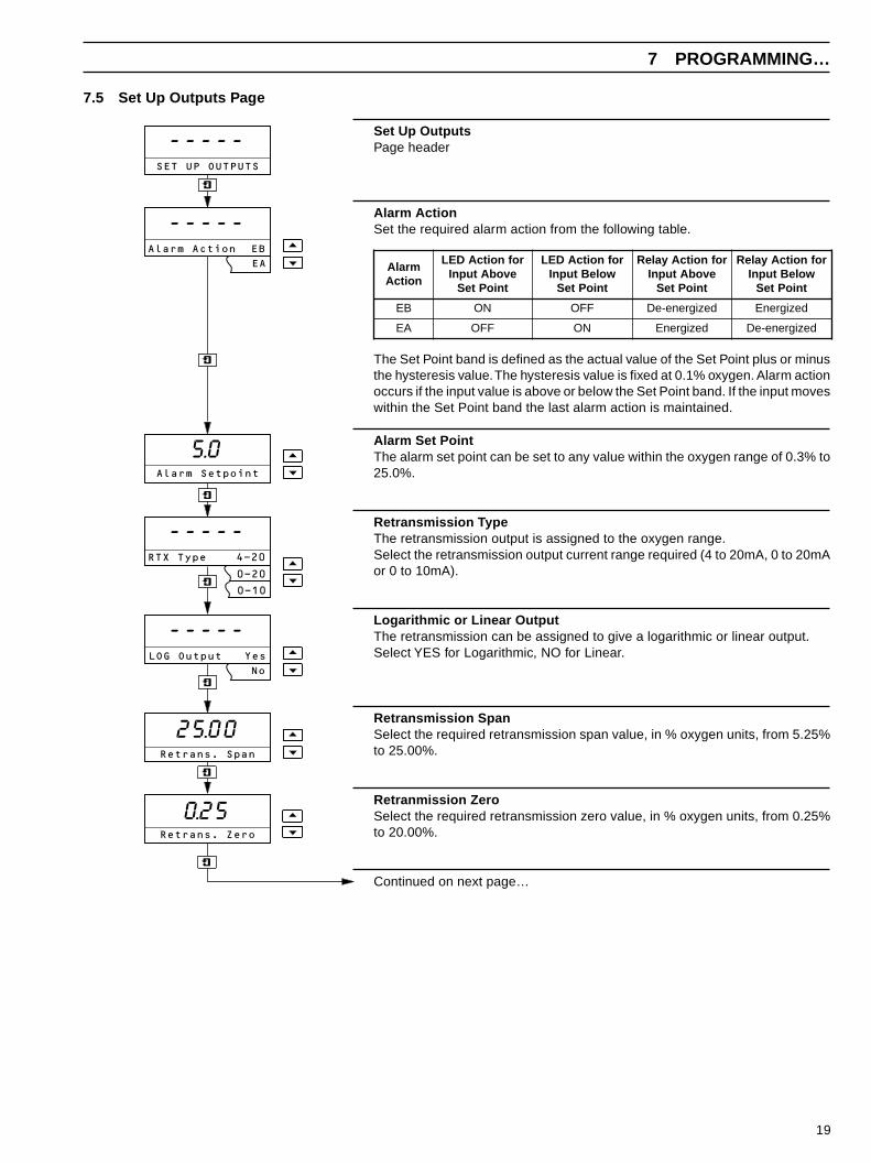
Set Up OutputsPage header
Alarm ActionSet the required alarm action from the following table.
The Set Point band is defined as the actual value of the Set Point plus or minusthe hysteresis value. The hysteresis value is fixed at 0.1% oxygen. Alarm actionoccurs if the input value is above or below the Set Point band. If the input moveswithin the Set Point band the last alarm action is maintained.
Alarm Set PointThe alarm set point can be set to any value within the oxygen range of 0.3% to25.0%.
Retransmission TypeThe retransmission output is assigned to the oxygen range.Select the retransmission output current range required (4 to 20mA, 0 to 20mAor 0 to 10mA).
Logarithmic or Linear OutputThe retransmission can be assigned to give a logarithmic or linear output.Select YES for Logarithmic, NO for Linear.
Retransmission SpanSelect the required retransmission span value, in % oxygen units, from 5.25%to 25.00%.
Retranmission ZeroSelect the required retransmission zero value, in % oxygen units, from 0.25%to 20.00%.
Continued on next page…
-----SET UP OUTPUTS
5.0Alarm Setpoint
-----Alarm Action EB
EA
-----RTX Type 4-20
0-20
0-10
-----LOG Output Yes
No
25.00Retrans. Span
0.25Retrans. Zero
mralAnoitcA
rofnoitcADELevobAtupnI
tnioPteS
rofnoitcADELwoleBtupnItnioPteS
rofnoitcAyaleRevobAtupnI
tnioPteS
rofnoitcAyaleRwoleBtupnItnioPteS
BE NO FFO dezigrene-eD dezigrenE
AE FFO NO dezigrenE dezigrene-eD
20
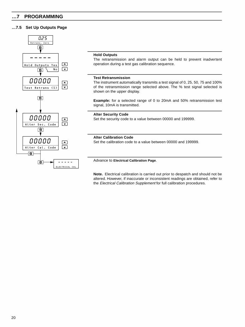
…7.5 Set Up Outputs Page
Hold OutputsThe retransmission and alarm output can be held to prevent inadvertentoperation during a test gas calibration sequence.
Test RetransmissionThe instrument automatically transmits a test signal of 0, 25, 50, 75 and 100%of the retransmission range selected above. The % test signal selected isshown on the upper display.
Example: for a selected range of 0 to 20mA and 50% retransmission testsignal, 10mA is transmitted.
Alter Security CodeSet the security code to a value between 00000 and 199999.
Alter Calibration CodeSet the calibration code to a value between 00000 and 199999.
Advance to Electrical Calibration Page.
Note. Electrical calibration is carried out prior to despatch and should not bealtered. However, if inaccurate or inconsistent readings are obtained, refer tothe Electrical Calibration Supplement for full calibration procedures.
–––––Hold Outputs Yes
No
00000Test Retrans (%)
-----ELECTRICAL CAL
00000Alter Sec. Code
00000Alter Cal. Code
0.25Retrans. Zero
…7 PROGRAMMING

PRODUCTS & CUSTOMER SUPPORT
ProductsAutomation Systems
• for the following industries:– Chemical & Pharmaceutical– Food & Beverage– Manufacturing– Metals and Minerals– Oil, Gas & Petrochemical– Pulp and Paper
Drives and Motors• AC and DC Drives, AC and DC Machines, AC Motors to 1kV• Drive Systems• Force Measurement• Servo Drives
Controllers & Recorders• Single and Multi-loop Controllers• Circular Chart and Strip Chart Recorders• Paperless Recorders• Process Indicators
Flexible Automation• Industrial Robots and Robot Systems
Flow Measurement• Electromagnetic Flowmeters• Mass Flow Meters• Turbine Flowmeters• Flow Elements
Marine Systems & Turbochargers• Electrical Systems• Marine Equipment• Offshore Retrofit and Refurbishment
Process Analytics• Process Gas Analysis• Systems Integration
Transmitters• Pressure• Temperature• Level• Interface Modules
Valves, Actuators and Positioners• Control Valves• Actuators• Positioners
Water, Gas & Industrial Analytics Instrumentation• pH, Conductivity and Dissolved Oxygen Transmitters and
Sensors• Ammonia, Nitrate, Phosphate, Silica, Sodium, Chloride,
Fluoride, Dissolved Oxygen and Hydrazine Analyzers• Zirconia Oxygen Analyzers, Katharometers, Hydrogen Purity
and Purge-gas Monitors, Thermal Conductivity
Customer Support
We provide a comprehensive after sales service via a WorldwideService Organization. Contact one of the following offices fordetails on your nearest Service and Repair Centre.
United KingdomABB LimitedTel: +44 (0)1453 826661Fax: +44 (0)1453 829671
United States of AmericaABB Inc.Tel: +1 (0) 775 850 4800Fax: +1 (0) 775 850 4808
Client Warranty
Prior to installation, the equipment referred to in this manual mustbe stored in a clean, dry environment, in accordance with theCompany's published specification.
Periodic checks must be made on the equipment's condition. Inthe event of a failure under warranty, the following documentationmust be provided as substantiation:
1. A listing evidencing process operation and alarm logs at time offailure.
2. Copies of all storage, installation, operating and maintenancerecords relating to the alleged faulty unit.

IM/E
XGP
–460
0Is
sue
5
The Company’s policy is one of continuous productimprovement and the right is reserved to modify the
information contained herein without notice.
Printed in UK (06.05)
© ABB 2005
ABB LimitedOldends Lane, StonehouseGloucestershireGL10 3TAUKTel: +44 (0)1453 826661Fax: +44 (0)1453 829671
ABB Inc.Analytical Instruments9716 S. Virginia St., Ste. EReno, Nevada 89521USATel: +1 (0) 775 850 4800Fax: +1 (0) 775 850 4808
ABB has Sales & Customer Supportexpertise in over 100 countries worldwide
www.abb.com