modbus interface module
TRANSCRIPT
User’s Manual(Hardware)
QJ71MB91
Thank you for purchasing the Mitsubishi programmable controller MELSEC-Q Series.
© 2005 MITSUBISHI ELECTRIC CORPORATION
MODBUS®
Interface Module
Prior to use, please read both this and the detailed manual thoroughly and familiarize yourself with the product.
MODEL QJ71MB91-U-HWMODELCODE 13JP83
IB(NA)-0800329-D(0808)MEE
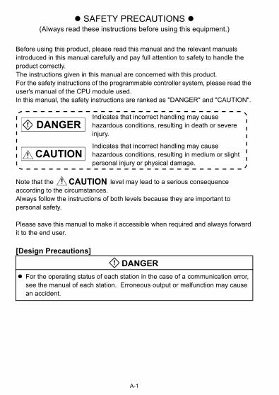
SAFETY PRECAUTIONS (Always read these instructions before using this equipment.)
Before using this product, please read this manual and the relevant manuals introduced in this manual carefully and pay full attention to safety to handle the product correctly.The instructions given in this manual are concerned with this product.For the safety instructions of the programmable controller system, please read the user's manual of the CPU module used.In this manual, the safety instructions are ranked as "DANGER" and "CAUTION".
Note that the level may lead to a serious consequence according to the circumstances. Always follow the instructions of both levels because they are important to personal safety.
Please save this manual to make it accessible when required and always forward it to the end user.
[Design Precautions]
Indicates that incorrect handling may cause hazardous conditions, resulting in death or severe injury.
Indicates that incorrect handling may cause hazardous conditions, resulting in medium or slight personal injury or physical damage.
For the operating status of each station in the case of a communication error, see the manual of each station. Erroneous output or malfunction may cause an accident.
DANGER
CAUTION
CAUTION
DANGER
A-1
[Design Precautions]
[Installation Precautions]
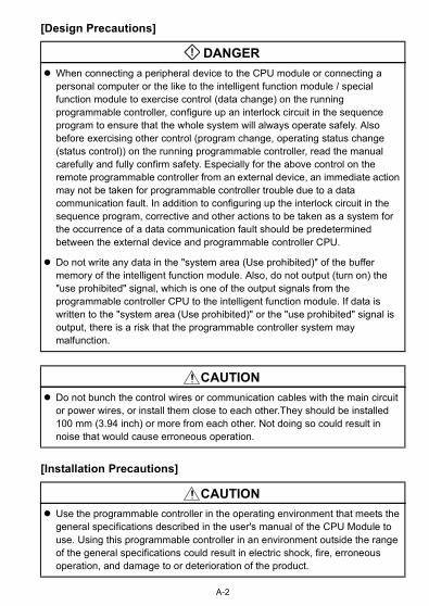
When connecting a peripheral device to the CPU module or connecting a personal computer or the like to the intelligent function module / special function module to exercise control (data change) on the running programmable controller, configure up an interlock circuit in the sequence program to ensure that the whole system will always operate safely. Also before exercising other control (program change, operating status change (status control)) on the running programmable controller, read the manual carefully and fully confirm safety. Especially for the above control on the remote programmable controller from an external device, an immediate action may not be taken for programmable controller trouble due to a data communication fault. In addition to configuring up the interlock circuit in the sequence program, corrective and other actions to be taken as a system for the occurrence of a data communication fault should be predetermined between the external device and programmable controller CPU.
Do not write any data in the "system area (Use prohibited)" of the buffer memory of the intelligent function module. Also, do not output (turn on) the "use prohibited" signal, which is one of the output signals from the programmable controller CPU to the intelligent function module. If data is written to the "system area (Use prohibited)" or the "use prohibited" signal is output, there is a risk that the programmable controller system may malfunction.
Do not bunch the control wires or communication cables with the main circuit or power wires, or install them close to each other.They should be installed 100 mm (3.94 inch) or more from each other. Not doing so could result in noise that would cause erroneous operation.
Use the programmable controller in the operating environment that meets the general specifications described in the user's manual of the CPU Module to use. Using this programmable controller in an environment outside the range of the general specifications could result in electric shock, fire, erroneous operation, and damage to or deterioration of the product.
DANGER
CAUTION
CAUTION
A-2
[Installation Precautions]
[Wiring Precautions]
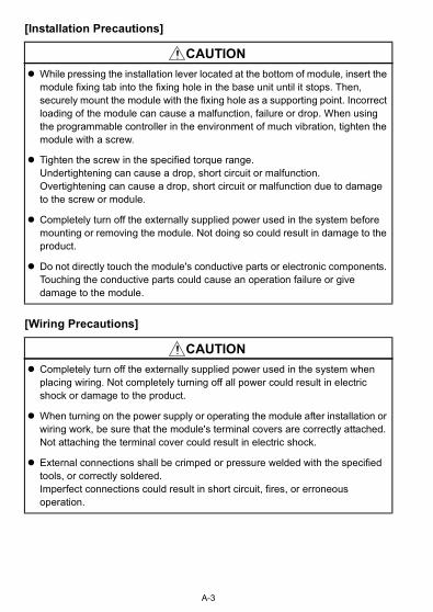
While pressing the installation lever located at the bottom of module, insert the module fixing tab into the fixing hole in the base unit until it stops. Then, securely mount the module with the fixing hole as a supporting point. Incorrect loading of the module can cause a malfunction, failure or drop. When using the programmable controller in the environment of much vibration, tighten the module with a screw.
Tighten the screw in the specified torque range. Undertightening can cause a drop, short circuit or malfunction. Overtightening can cause a drop, short circuit or malfunction due to damage to the screw or module.
Completely turn off the externally supplied power used in the system before mounting or removing the module. Not doing so could result in damage to the product.
Do not directly touch the module's conductive parts or electronic components. Touching the conductive parts could cause an operation failure or give damage to the module.
Completely turn off the externally supplied power used in the system when placing wiring. Not completely turning off all power could result in electric shock or damage to the product.
When turning on the power supply or operating the module after installation or wiring work, be sure that the module's terminal covers are correctly attached. Not attaching the terminal cover could result in electric shock.
External connections shall be crimped or pressure welded with the specified tools, or correctly soldered. Imperfect connections could result in short circuit, fires, or erroneous operation.
CAUTION
CAUTION
A-3
[Wiring Precautions]
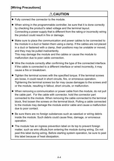
Fully connect the connector to the module.
When wiring in the programmable controller, be sure that it is done correctly by checking the product's rated voltage and the terminal layout. Connecting a power supply that is different from the rating or incorrectly wiring the product could result in fire or damage.
Make sure to place the communication and power cables to be connected to the module in a duct or fasten them using a clamp. If the cables are not placed in a duct or fastened with a clamp, their positions may be unstable or moved, and they may be pulled inadvertently.This may damage the module and the cables or cause the module to malfunction due to poor cable connection.
Wire the module correctly after confirming the type of the connected interface. If the cable is connected to a different interface or wired incorrectly, it may cause a fire or breakdown.
Tighten the terminal screws with the specified torque. If the terminal screws are loose, it could result in short circuits, fire, or erroneous operation. Tightening the terminal screws too far may cause damages to the screws and/or the module, resulting in fallout, short circuits, or malfunction.
When removing a communication or power cable from the module, do not pull the cable part. For the cable with connector, hold the connector part connected to the module. When removing the cable connected to the terminal block, first loosen the screws on the terminal block. Pulling a cable connected to the module may damage the module and/or cable and cause a malfunction due to poor contact.
Be sure there are no foreign substances such as sawdust or wiring debris inside the module. Such debris could cause fires, damage, or erroneous operation.
The module has an ingress prevention label on its top to prevent foreign matter, such as wire offcuts,from entering the module during wiring. Do not peel this label during wiring. Before starting system operation, be sure to peel this label because of heat dissipation.
CAUTION
A-4

[Startup/Maintenance Precautions]
Do not touch the terminals while power is on.Doing so could cause shock or erroneous operation.
Switch off all phases of the externally supplied power used in the system when cleaning the module or retightening the terminal or module mounting screws. Not doing so could result in electric shock. Undertightening of terminal screws can cause a short circuit or malfunction. Overtightening of screws can cause damages to the screws and/or the module, resulting in fallout, short circuits, or malfunction.
The online operations conducted for the CPU module being operated, connecting the peripheral device (especially, when changing data or operation status), shall be conducted after the manual has been carefully read and a sufficient check of safety has been conducted. Operation mistakes could cause damage or problems with of the module.
Do not disassemble or modify each modules.Doing so could cause failure, malfunction, injury or fire.
Use any radio communication device such as a cellular phone or a PHS phone more than 25cm (9.85 inch) away in all directions of the programmable controller. Not doing so can cause a malfunction.
Completely turn off the externally supplied power used in the system before mounting or removing the module. Not doing so could result in damage to the product.
Do not mount/remove the module to/from the base unit or terminal block more than 50 times (IEC 61131-2 compliant), after the first use of the product.Failure to do so may cause module malfunctions.
Before touching the module, always touch grounded metal, etc. to discharge static electricity from human body, etc. Not doing so can cause the module to fail or malfunction.
DANGER
CAUTION
A-5
[Operating Precautions]
[Disposal Precautions]
Please read the manual carefully and ensure the safety before performing control operations (especially, data or program modification and operation status change) to a running programmable controller. Incorrect data or program modifications or improper operating status change may cause system malfunctions, mechanical damages or accidents.
When disposing of this product, treat it as industrial waste.
CAUTION
CAUTION
A-6
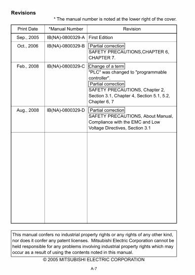
Revisions* The manual number is noted at the lower right of the cover.
© 2005 MITSUBISHI ELECTRIC CORPORATION
Print Date *Manual Number Revision
Sep., 2005 IB(NA)-0800329-A First Edition
Oct., 2006 IB(NA)-0800329-B Partial correctionSAFETY PRECAUTIONS,CHAPTER 6,CHAPTER 7.
Feb., 2008 IB(NA)-0800329-C Change of a term"PLC" was changed to "programmable controller". Partial correctionSAFETY PRECAUTIONS, Chapter 2, Section 3.1, Chapter 4, Section 5.1, 5.2, Chapter 6, 7
Aug., 2008 IB(NA)-0800329-D Partial correctionSAFETY PRECAUTIONS, About Manual, Compliance with the EMC and Low Voltage Directives, Section 3.1
This manual confers no industrial property rights or any rights of any other kind, nor does it confer any patent licenses. Mitsubishi Electric Corporation cannot be held responsible for any problems involving industrial property rights which may occur as a result of using the contents noted in this manual.
A-7
A-8
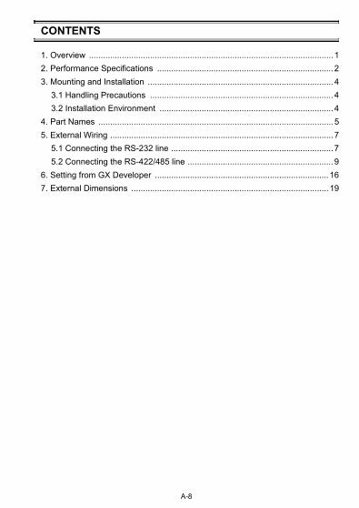
CONTENTS
1. Overview ........................................................................................................12. Performance Specifications ...........................................................................23. Mounting and Installation ...............................................................................4
3.1 Handling Precautions ..............................................................................43.2 Installation Environment ..........................................................................4
4. Part Names ....................................................................................................55. External Wiring ...............................................................................................7
5.1 Connecting the RS-232 line .....................................................................75.2 Connecting the RS-422/485 line ..............................................................9
6. Setting from GX Developer .......................................................................... 167. External Dimensions .................................................................................... 19

A-9
About Manual
The following manual is also related to this product.In necessary, order it by quoting the details in the table below.
Compliance with the EMC and Low Voltage Directives
(1) For programmable controller systemTo configure a system meeting the requirements of the EMC and Low Voltage Directives when incorporating the Mitsubishi programmable controller (EMC and LowVoltage Directives compliant) into other machinery or equipment, refer to Chapter 9 "EMC AND LOW VOLTAGE DIRECTIVES" of the QCPU User's Manual (Hardware Design, Maintenance and Inspection).The CE mark, indicating compliance with the EMC and Low Voltage Directives, is printed on the rating plate of the programmable controller.
(2) For the productNo additional measures are necessary for the compliance of this product with the EMC and Low Voltage Directives.
Related Manual
Manual name Manual No.(Model code)
MODBUS® Interface Module User's Manual SH-080578ENG(13JR86)
Before using this module, be sure to read the MODBUS® Interface Module User's Manual.
1. Overview
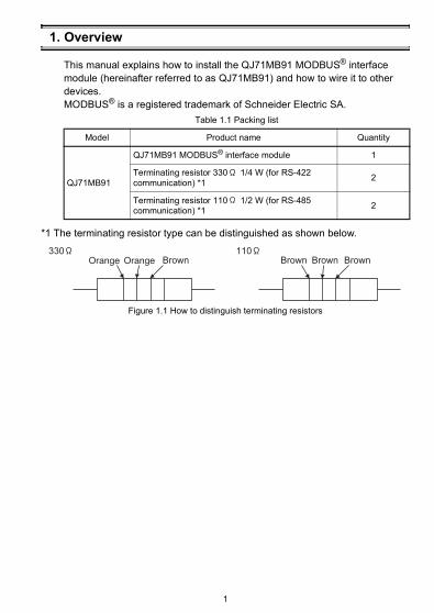
This manual explains how to install the QJ71MB91 MODBUS® interface module (hereinafter referred to as QJ71MB91) and how to wire it to other devices.MODBUS® is a registered trademark of Schneider Electric SA.
*1 The terminating resistor type can be distinguished as shown below.
Table 1.1 Packing list
Model Product name Quantity
QJ71MB91
QJ71MB91 MODBUS® interface module 1
Terminating resistor 330 1/4 W (for RS-422 communication) *1 2
Terminating resistor 110 1/2 W (for RS-485 communication) *1 2
Figure 1.1 How to distinguish terminating resistors
Brown Brown Brown BrownOrange Orange330 110
1
2. Performance Specifications
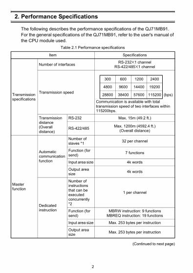
The following describes the performance specifications of the QJ71MB91.For the general specifications of the QJ71MB91, refer to the user's manual of the CPU module used.
(Continued to next page)
Table 2.1 Performance specifications
Item Specifications
Transmission specifications
Number of interfaces RS-232 1 channelRS-422/485 1 channel
Transmission speed
Communication is available with total transmission speed of two interfaces within 115200bps.
Transmission distance(Overall distance)
RS-232 Max. 15m (49.2 ft.)
RS-422/485 Max. 1200m (4592.4 ft.)(Overall distance)
Master function
Automatic communication function
Number of slaves *1 32 per channel
Function (for send) 7 functions
Input area size 4k words
Output area size 4k words
Dedicated instruction
Number of instructions that can be executed concurrently *2
1 per channel
Function (for send)
MBRW instruction: 9 functionsMBREQ instruction: 19 functions
Input area size Max. 253 bytes per instruction
Output area size Max. 253 bytes per instruction
300 600 1200 2400
4800 9600 14400 19200
28800 38400 57600 115200 (bps)
2
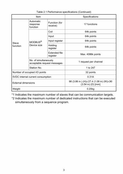
*1 Indicates the maximum number of slaves that can be communication targets.*2 Indicates the maximum number of dedicated instructions that can be executed
simultaneously from a sequence program.
Table 2.1 Performance specifications (Continued)
Item Specifications
Slave function
Automatic response function
Function (for receive) 17 functions
MODBUS® Device size
Coil 64k points
Input 64k points
Input register 64k points
Holding register 64k points
Extended file register Max. 4086k points
No. of simultaneously acceptable request messages 1 request per channel
Station No. 1 to 247
Number of occupied I/O points 32 points
5VDC internal current consumption 0.31A
External dimensions 98 (3.86 in.) (H) 27.4 (1.08 in) (W) 90(3.54 in) (D) [mm]
Weight 0.20kg
3
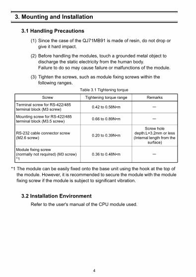
3. Mounting and Installation
3.1 Handling Precautions
(1) Since the case of the QJ71MB91 is made of resin, do not drop or give it hard impact.
(2) Before handling the modules, touch a grounded metal object to discharge the static electricity from the human body.Failure to do so may cause failure or malfunctions of the module.
(3) Tighten the screws, such as module fixing screws within the following ranges.
*1 The module can be easily fixed onto the base unit using the hook at the top of the module. However, it is recommended to secure the module with the module fixing screw if the module is subject to significant vibration.
3.2 Installation EnvironmentRefer to the user's manual of the CPU module used.
Table 3.1 Tightening torque
Screw Tightening torque range Remarks
Terminal screw for RS-422/485 terminal block (M3 screw) 0.42 to 0.58N•m
Mounting screw for RS-422/485 terminal block (M3.5 screw) 0.66 to 0.89N•m
RS-232 cable connector screw (M2.6 screw) 0.20 to 0.39N•m
Screw hole depth:L=3.2mm or less (Internal length from the
surface)
Module fixing screw(normally not required) (M3 screw) *1
0.36 to 0.48N•m
4
4. Part Names
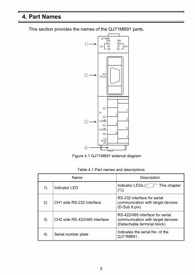
This section provides the names of the QJ71MB91 parts.
Figure 4.1 QJ71MB91 external diagram
Table 4.1 Part names and descriptions
Name Description
1) Indicator LED Indicator LEDs ( This chapter (1))
2) CH1 side RS-232 interfaceRS-232 interface for serial communication with target devices (D-Sub 9 pin)
3) CH2 side RS-422/485 interfaceRS-422/485 interface for serial communication with target devices (Detachable terminal block)
4) Serial number plate Indicates the serial No. of the QJ71MB91.
5
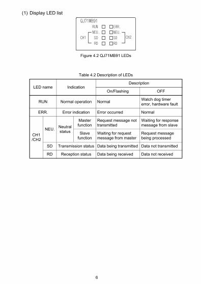
(1) Display LED list
Figure 4.2 QJ71MB91 LEDs
Table 4.2 Description of LEDs
LED name IndicationDescription
On/Flashing OFF
RUN Normal operation Normal Watch dog timer error, hardware fault
ERR. Error indication Error occurred Normal
CH1/CH2
NEU. Neutral status
Master function
Request message not transmitted
Waiting for response message from slave
Slave function
Waiting for request message from master
Request message being processed
SD Transmission status Data being transmitted Data not transmitted
RD Reception status Data being received Data not received
6
5. External Wiring
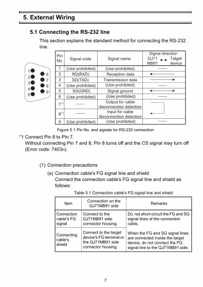
5.1 Connecting the RS-232 lineThis section explains the standard method for connecting the RS-232 line.
*1 Connect Pin 8 to Pin 7.Without connecting Pin 7 and 8, Pin 8 turns off and the CS signal may turn off (Error code: 7403H).
(1) Connection precautions
(a) Connection cable's FG signal line and shieldConnect the connection cable's FG signal line and shield as follows:
Figure 5.1 Pin No. and signals for RS-232 connection
Table 5.1 Connection cable's FG signal line and shield
Item Connection on the QJ71MB91 side Remarks
Connection cable's FG signal
Connect to the QJ71MB91 side connector housing.
Do not short-circuit the FG and SG signal lines of the connection cable.
When the FG and SG signal lines are connected inside the target device, do not connect the FG signal line to the QJ71MB91 side.
Connecting cable's shield
Connect to the target device's FG terminal or the QJ71MB91 side connector housing.
Reception data
Transmission data
Signal ground
SD(TXD)
1
2
3
4
5
6
7*1
8*1
9
9
1
2
3
4
5
6
7
8
(Use prohibited)(Use prohibited)
(Use prohibited)
(Use prohibited)
(Use prohibited)
Pin No.
QJ71MB91
Signal name
Signal direction
Tatget device
(Use prohibited)
(Use prohibited)
(Use prohibited)
RD(RXD)
SG(GND)
Signal code
Output for cable disconnection detection
Input for cable disconnection detection
7
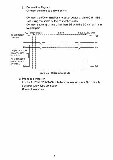
(b) Connection diagramConnect the lines as shown below.
Connect the FG terminal on the target device and the QJ71MB91 side using the shield of the connection cable.Connect each signal line other than SG with the SG signal line in twisted pair.
(2) Interface connectorFor the QJ71MB91 RS-232 interface connector, use a 9-pin D sub (female) screw type connector.Use metric screws.
Figure 5.2 RS-232 cable shield
FG
RD
SD
SG
RD
SD
SG
QJ71MB91 side To connector housing
Output for cable disconnection detection
Input for cable disconnection detection
Shield Target device side
8
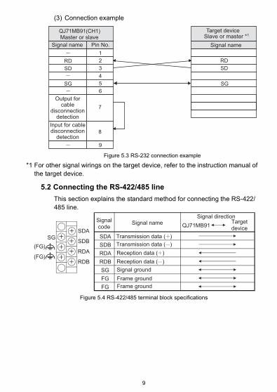
(3) Connection example
*1 For other signal wirings on the target device, refer to the instruction manual of the target device.
5.2 Connecting the RS-422/485 lineThis section explains the standard method for connecting the RS-422/485 line.
Figure 5.3 RS-232 connection example
Figure 5.4 RS-422/485 terminal block specifications
1
2
3
4
5
6
7
8
9
RD
SD
RD
SD
QJ71MB91(CH1)
SG SG
Target device
Master or slave Slave or master *1
Signal nameSignal name Pin No.
Output for cable
disconnection detection
Input for cable disconnection
detection
SDA
QJ71MB91
SG
SDA
SDB
RDA
RDB
SDB
RDA
RDB
SG
FG
FG
(FG)
(FG)
Signal code
Signal nameSignal direction
Target device
Reception data ( )
Reception data ( )
Transmission data ( )
Transmission data ( )
Signal ground
Frame ground
Frame ground
9
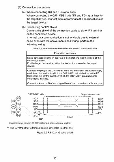
(1) Connection precautions
(a) When connecting SG and FG signal linesWhen connecting the QJ71MB91 side SG and FG signal lines to the target device, connect them according to the specifications of the target device.
(b) Connecting cable's shieldConnect the shield of the connection cable to either FG terminal on the connected device.If normal data communication is not available due to external noise even with the above-mentioned wiring, perform the following wiring.
Table 5.2 When external noise disturbs normal communications
Preventive measures
Make connection between the FGs of both stations with the shield of the connection cable.For the target device side, follow the instruction manual of the target device.
Connect the (FG) of the QJ71MB91 to the FG terminal of the power supply module on the station to which the QJ71MB91 is installed, or to the FG terminal of the control panel on which the QJ71MB91 programmable controller is installed.
Connect nnA and nnB of each signal line of the connection cable in a pair.
*1 The QJ71MB91's FG terminal can be connected to either one.
Figure 5.5 RS-422/485 cable shield
SDA
SDB
SDA
SDB
RDARDBSG
RDARDB
SG
FG
SG
FG
FG
SDA
RDA
RDB
SDB
(FG)*1(FG)*1
QJ71MB91 side
Shield
Target device side
Correspondence between RS-422/485 terminal block and signal position.
10
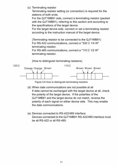
(c) Terminating resistorTerminating resistor setting (or connection) is required for the stations of both ends.For the QJ71MB91 side, connect a terminating resistor (packed with the QJ71MB91), referring to this section and according to the specifications of the target device.For the target device side, connect or set a terminating resistor according to the instruction manual of the target device.
(Terminating resistor to be connected to the QJ71MB91)For RS-422 communications, connect a "330 1/4 W" terminating resistor.For RS-485 communications, connect a "110 1/2 W" terminating resistor.
(How to distinguish terminating resistors)
(d) When data communications are not possible at allIf data cannot be exchanged with the target device at all, check the polarity of the target device. If the polarities of the QJ71MB91 and the target device do not match, reverse the polarity of each signal on either device side. This may enable the data communications.
(e) Devices connected to RS-422/485 interfaceDevices connected to the QJ71MB91 RS-422/485 interface must be all RS-422 or all RS-485.
Figure 5.6 How to distinguish terminating resistors
Brown Brown Brown BrownOrange Orange330 110
11
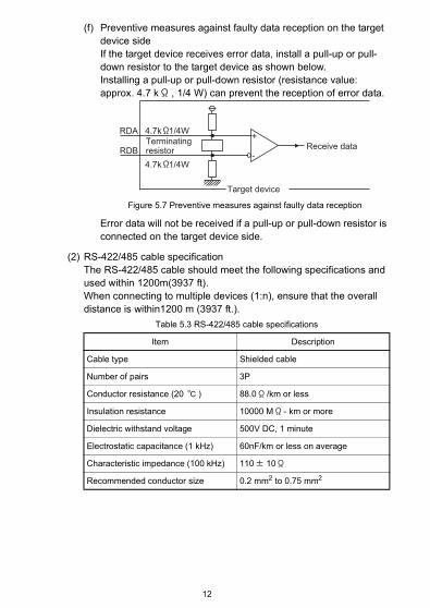
(f) Preventive measures against faulty data reception on the target device sideIf the target device receives error data, install a pull-up or pull-down resistor to the target device as shown below.Installing a pull-up or pull-down resistor (resistance value: approx. 4.7 k , 1/4 W) can prevent the reception of error data.
Error data will not be received if a pull-up or pull-down resistor is connected on the target device side.
(2) RS-422/485 cable specificationThe RS-422/485 cable should meet the following specifications and used within 1200m(3937 ft).When connecting to multiple devices (1:n), ensure that the overall distance is within1200 m (3937 ft.).
Figure 5.7 Preventive measures against faulty data reception
Table 5.3 RS-422/485 cable specifications
Item Description
Cable type Shielded cable
Number of pairs 3P
Conductor resistance (20 ) 88.0 /km or less
Insulation resistance 10000 M - km or more
Dielectric withstand voltage 500V DC, 1 minute
Electrostatic capacitance (1 kHz) 60nF/km or less on average
Characteristic impedance (100 kHz) 110 10
Recommended conductor size 0.2 mm2 to 0.75 mm2
+
-
RDA
RDB
4.7k 1/4W
4.7k 1/4W
Terminating resistor
Target device
Receive data
12
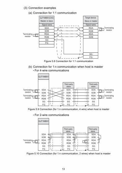
(3) Connection examples
(a) Connection for 1:1 communication
(b) Connection for 1:n communication when host is master• For 4-wire communications
• For 2-wire communications
Figure 5.8 Connection for 1:1 communication
Figure 5.9 Connection (for 1:n communication, 4 wire) when host is master
Figure 5.10 Connection (for 1:n communication, 2 wires) when host is master
RRDA
SG
FG
SDA RDA
SG
FG
SDA
R
QJ71MB91(CH2)
SDB
RDB
RDB
SDB
Master or slave Slave or master
Target device
Signal name Signal name
Terminating resistor
Terminating resistor
R
RDA
SG
FG
SDAR
RRDA
SG
FG
QJ71MB91
SDA
R
SDB
RDB RDB
SDB
RDA
SG
FG
SDA
RDB
SDB
Terminating resistor
Terminating resistor
Terminating resistor
Terminating resistor
Third party slave
Third party slave
RDA
SG
FG
SDA
R R
SDB
RDB
RDA
SG
FG
SDA
SDB
RDB
RDA
SG
FG
SDA
SDB
RDB
QJ71MB91
Terminating resistor
Third party slave
Third party slave
13
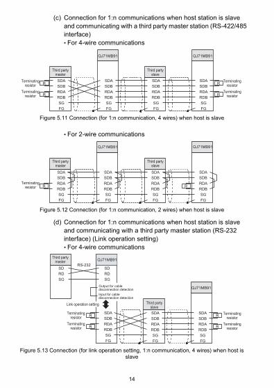
(c) Connection for 1:n communications when host station is slave and communicating with a third party master station (RS-422/485 interface)• For 4-wire communications
• For 2-wire communications
(d) Connection for 1:n communications when host station is slave and communicating with a third party master station (RS-232 interface) (Link operation setting)• For 4-wire communications
Figure 5.11 Connection (for 1:n communication, 4 wires) when host is slave
Figure 5.12 Connection (for 1:n communication, 2 wires) when host is slave
Figure 5.13 Connection (for link operation setting, 1:n communication, 4 wires) when host is slave
RDA
SG
FG
SDAR
R
SDB
RDB
RDA
SG
FG
SDA
SDB
RDB
RDA
SG
FG
SDA
SDB
RDB
RDA
SG
FG
SDA
SDB
RDB
R
R
QJ71MB91 QJ71MB91
Terminating resistor
Terminating resistor
Terminating resistor
Terminating resistor
Third party master
Third party slave
QJ71MB91
R RRDA
SG
FG
SDA
SDB
RDB
RDA
SG
FG
SDA
SDB
RDB
RDA
SG
FG
SDA
SDB
RDB
RDA
SG
FG
SDA
SDB
RDB
QJ71MB91
Terminating resistor
Third party master
Third party slave
R R
RRRDA
SG
FG
SDA
SDB
RDB
RDA
SG
FG
SDA
SDB
RDB
RDA
SG
FG
SDA
SDB
RDB
QJ71MB91
SG
SD
RD
SG
SD
RD
QJ71MB91
RS-232
Terminating resistor
Terminating resistor
Terminating resistor
Terminating resistor
Third party master
Third party slave
Input for cable disconnection detection
Output for cable disconnection detection
Link operation setting
14
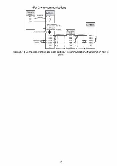
• For 2-wire communications
Figure 5.14 Connection (for link operation setting, 1:n communication, 2 wires) when host is slave
SG
SD
RD
RDA
SG
FG
SDA
SDB
RDB
QJ71MB91
QJ71MB91
R
RS-232
RDA
SG
FG
SDA
SDB
RDB
RDA
SG
FG
SDA
SDB
RDBR
SG
SD
RD
QJ71MB91
Terminating resistor
Third party master
Third party slave
Input for cable disconnection detection
Output for cable disconnection detection
Link operation setting
15
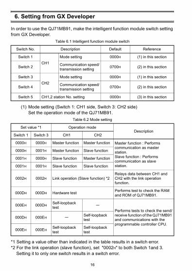
6. Setting from GX Developer
In order to use the QJ71MB91, make the intelligent function module switch setting from GX Developer.
(1) Mode setting (Switch 1: CH1 side, Switch 3: CH2 side)Set the operation mode of the QJ71MB91.
*1 Setting a value other than indicated in the table results in a switch error.*2 For the link operation (slave function), set "0002H" to both Switch 1and 3.
Setting it to only one switch results in a switch error.
Table 6.1 Intelligent function module switch
Switch No. Description Default Reference
Switch 1CH1
Mode setting 0000H (1) in this section
Switch 2 Communication speed/transmission setting 0700H (2) in this section
Switch 3CH2
Mode setting 0000H (1) in this section
Switch 4 Communication speed/transmission setting 0700H (2) in this section
Switch 5 CH1,2 station No. setting 0000H (3) in this section
Table 6.2 Mode setting
Set value *1 Operation modeDescription
Switch 1 Switch 3 CH1 CH2
0000H 0000H Master function Master function Master function : Performs communication as masterstation.Slave function : Performs communication as slavestation.
0000H 0001H Master function Slave function
0001H 0000H Slave function Master function
0001H 0001H Slave function Slave function
0002H 0002H Link operation (Slave function) *2Relays data between CH1 and CH2 with the link operation function.
000DH 000DH Hardware test Performs test to check the RAM and ROM of QJ71MB91.
000EH 000DHSelf-loopback test
Performs tests to check the send/receive function of the QJ71MB91 and communications with the programmable controller CPU.
000DH 000EHSelf-loopback test
000EH 000EHSelf-loopback test
Self-loopback test
16
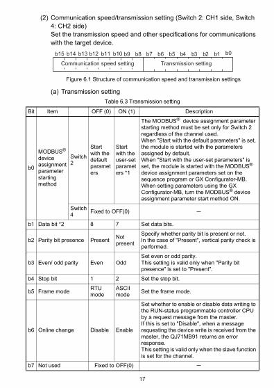
(2) Communication speed/transmission setting (Switch 2: CH1 side, Switch 4: CH2 side)Set the transmission speed and other specifications for communications with the target device.
(a) Transmission setting
Figure 6.1 Structure of communication speed and transmission settings
Table 6.3 Transmission setting
Bit Item OFF (0) ON (1) Description
b0
MODBUS® device assignment parameter starting method
Switch 2
Start with the default parameters
Start with the user-set parameters *1
The MODBUS® device assignment parameter starting method must be set only for Switch 2 regardless of the channel used.When "Start with the default parameters" is set, the module is started with the parameters assigned by default.When "Start with the user-set parameters" is set, the module is started with the MODBUS® device assignment parameters set on the sequence program or GX Configurator-MB.When setting parameters using the GX Configurator-MB, turn the MODBUS® device assignment parameter start method ON.
Switch 4 Fixed to OFF(0)
b1 Data bit *2 8 7 Set data bits.
b2 Parity bit presence Present Not present
Specify whether parity bit is present or not.In the case of "Present", vertical parity check is performed.
b3 Even/ odd parity Even OddSet even or odd parity.This setting is valid only when "Parity bit presence" is set to "Present".
b4 Stop bit 1 2 Set the stop bit.
b5 Frame mode RTU mode
ASCII mode Set the frame mode.
b6 Online change Disable Enable
Set whether to enable or disable data writing to the RUN-status programmable controller CPU by a request message from the master.If this is set to "Disable", when a message requesting the device write is received from the master, the QJ71MB91 returns an error response.This setting is valid only when the slave function is set for the channel.
b7 Not used Fixed to OFF(0)
b0b1b2b3b4b5b6b7b8b9b15 b14 b13 b12 b11 b10
Communication speed setting Transmission setting
17
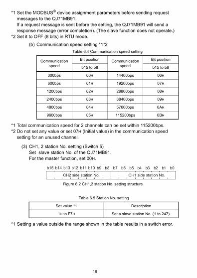
*1 Set the MODBUS® device assignment parameters before sending request messages to the QJ71MB91.If a request message is sent before the setting, the QJ71MB91 will send a response message (error completion). (The slave function does not operate.)
*2 Set it to OFF (8 bits) in RTU mode.
(b) Communication speed setting *1*2
*1 Total communication speed for 2 channels can be set within 115200bps.*2 Do not set any value or set 07H (Initial value) in the communication speed
setting for an unused channel.
(3) CH1, 2 station No. setting (Switch 5)Set slave station No. of the QJ71MB91.For the master function, set 00H.
*1 Setting a value outside the range shown in the table results in a switch error.
Table 6.4 Communication speed setting
Communication speed
Bit position Communication speed
Bit position
b15 to b8 b15 to b8
300bps 00H 14400bps 06H
600bps 01H 19200bps 07H
1200bps 02H 28800bps 08H
2400bps 03H 38400bps 09H
4800bps 04H 57600bps 0AH
9600bps 05H 115200bps 0BH
Figure 6.2 CH1,2 station No. setting structure
Table 6.5 Station No. setting
Set value *1 Description
1H to F7H Set a slave station No. (1 to 247).
b0b1b2b3b4b5b6b7b8b9b15 b14 b13 b12 b11 b10
CH1 side station No.CH2 side station No.
18
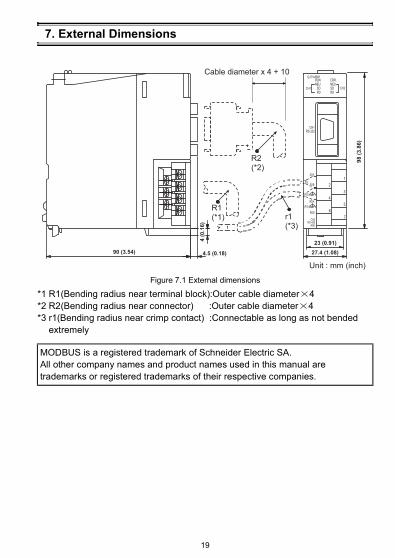
7. External Dimensions
*1 R1(Bending radius near terminal block):Outer cable diameter 4*2 R2(Bending radius near connector) :Outer cable diameter 4*3 r1(Bending radius near crimp contact) :Connectable as long as not bended
extremely
Figure 7.1 External dimensions
MODBUS is a registered trademark of Schneider Electric SA.All other company names and product names used in this manual are trademarks or registered trademarks of their respective companies.
19

WarrantyMitsubishi will not be held liable for damage caused by factors found not to be the cause of
Mitsubishi; machine damage or lost profits caused by faults in the Mitsubishi products; damage, secondary damage, accident compensation caused by special factors unpredictable by Mitsubishi; damages to products other than Mitsubishi products; and to other duties.
For safe use• This product has been manufactured as a general-purpose part for general industries, and
has not been designed or manufactured to be incorporated in a device or system used in purposes related to human life.
• Before using the product for special purposes such as nuclear power, electric power, aerospace, medicine or passenger movement vehicles, consult with Mitsubishi.
• This product has been manufactured under strict quality control. However, when installing the product where major accidents or losses could occur if the product fails, install appropriate backup or failsafe functions in the system.
Country/Region Sales office/Tel
Specifications subject to change without notice.
Printed in Japan on recycled paper.
Country/Region Sales office/Tel
U.S.A Mitsubishi Electric Automation Inc. 500 Corporate Woods Parkway Vernon Hills, IL 60061, U.S.A. Tel : +1-847-478-2100Brazil MELCO-TEC Rep. Com.e Assessoria Tecnica Ltda. Rua Correia Dias, 184, Edificio Paraiso Trade Center-8 andar Paraiso, Sao Paulo, SP Brazil Tel : +55-11-5908-8331Germany Mitsubishi Electric Europe B.V. German Branch Gothaer Strasse 8 D-40880 Ratingen, GERMANY Tel : +49-2102-486-0U.K Mitsubishi Electric Europe B.V. UK Branch Travellers Lane, Hatfield, Hertfordshire., AL10 8XB, U.K. Tel : +44-1707-276100Italy Mitsubishi Electric Europe B.V. Italian Branch Centro Dir. Colleoni, Pal. Perseo-Ingr.2 Via Paracelso 12, I-20041 Agrate Brianza., Milano, Italy Tel : +39-039-60531Spain Mitsubishi Electric Europe B.V. Spanish Branch Carretera de Rubi 76-80, E-08190 Sant Cugat del Valles, Barcelona, Spain Tel : +34-93-565-3131France Mitsubishi Electric Europe B.V. French Branch 25, Boulevard des Bouvets, F-92741 Nanterre Cedex, France TEL: +33-1-5568-5568South Africa Circuit Breaker Industries Ltd. Private Bag 2016, ZA-1600 Isando, South Africa Tel : +27-11-928-2000
Hong Kong Mitsubishi Electric Automation (Hong Kong) Ltd. 10th Floor, Manulife Tower, 169 Electric Road, North Point, Hong Kong Tel : +852-2887-8870China Mitsubishi Electric Automation (Shanghai) Ltd. 4/F Zhi Fu Plazz, No.80 Xin Chang Road, Shanghai 200003, China Tel : +86-21-6120-0808Taiwan Setsuyo Enterprise Co., Ltd. 6F No.105 Wu-Kung 3rd.Rd, Wu-Ku Hsiang, Taipei Hsine, Taiwan Tel : +886-2-2299-2499Korea Mitsubishi Electric Automation Korea Co., Ltd. 1480-6, Gayang-dong, Gangseo-ku Seoul 157-200, Korea Tel : +82-2-3660-9552Singapore Mitsubishi Electric Asia Pte, Ltd. 307 Alexandra Road #05-01/02, Mitsubishi Electric Building, Singapore 159943 Tel : +65-6470-2460Thailand Mitsubishi Electric Automation (Thailand) Co., Ltd. Bang-Chan Industrial Estate No.111 Moo 4, Serithai Rd, T.Kannayao, A.Kannayao, Bangkok 10230 Thailand Tel : +66-2-517-1326Indonesia P.T. Autoteknindo Sumber Makmur Muara Karang Selatan, Block A/Utara No.1 Kav. No.11 Kawasan Industri Pergudangan Jakarta - Utara 14440, P.O.Box 5045 Jakarta, 11050 Indonesia Tel : +62-21-6630833India Messung Systems Pvt, Ltd. Electronic Sadan NO:III Unit No15, M.I.D.C Bhosari, Pune-411026, India Tel : +91-20-2712-3130Australia Mitsubishi Electric Australia Pty. Ltd. 348 Victoria Road, Rydalmere, N.S.W 2116, Australia Tel : +61-2-9684-7777
HEAD OFFICE : TOKYO BUILDING, 2-7-3 MARUNOUCHI, CHIYODA-KU, TOKYO 100-8310, JAPAN
NAGOYA WORKS : 1-14, YADA-MINAMI 5-CHOME, HIGASHI-KU, NAGOYA, JAPAN
When exported from Japan, this manual does not require application to the Ministry of Economy, Trade and Industry for service transaction permission.