bus module modbus tcp - advanced energy · • the ethernet bus module modbus tcp interface module...
TRANSCRIPT

1
BUS MODULE MODBUS TCP FOR THYRO-S, THYRO-A, THYRO-AX, THYRO-POWER MANAGER,
THYRO-STEP CONTROLLER, THYRO-MEASUREMENT UNIT,
THYRO-A ...C01, ...C02, ...C03, ...C05 AND ...C07
July 2014 DE/EN - V3

2
List of tables and figures 5
Abbreviations 6
1. Safety instructions 7
1.1 Obligation to give instructions 7
1.2 Proper use 7
1.3 Residual hazards of the product 8
1.4 Maloperation and its results 8
1.5 Scope of supply 8
1.6 Storing 8
1.7 Installation 9
1.8 Connection 9
1.9 Operation 9
1.10 Maintenance, Service, Malfunctions 9
1.11 Decommissioning and removal 11
2. Safety regulations 12
2.1 Important instructions and explanations 12
2.2 Accident prevention rules 13
2.3 Qualified personnel 14
2.4 Operator requirements 14
2.5 Intended use 15
2.6 Liability 15
3. Remarks on the present operating instructions 16
3.1 Validity 16
3.2 Handling 16
3.3 Warranty 16
3.4 Copyright 17
3.5 Copyright notice 17
4. Contact information 18
4.1 Technical queries 18
4.2 Commercial queries 18
CONTENTS

3
4.3 Service 18
4.4 Internet 18
5. Introduction 19
5.1 General 19
5.2 Special features 19
5.3 Type designation 19
6. Functions 20
6.1 Processing the set point Thyro-S 20
6.2 Processing the set point Thyro-A/Thyro-AX 20
6.3 Processing the set point Thyro-Step Controller 21
6.4 Freely addressable digital outputs 22
7. Installation 23
7.1 Connection Terminals (overview) 23
7.2 Connecting a 24 V Power Supply 23
7.3 Connecting the Power Controller to X1-X8 24
7.4 Connecting the Ethernet Bus Module to the master 24
8. Settings 25
8.1 Setting the Protocol 25
8.2 Setting the Number of Slots 25
8.3 Setting the IP Address 25
8.4 Configuration and LED displays 26
9. Modbus TCP Protocol 28
9.1 General information 28
9.2 General telegram set up with the Modbus TCP 28
9.3 Handling exceptions 29
9.4 Modbus data types 30
9.5 Functions 31
9.5.1 Read Holding Registers (0x03) 32
9.5.2 Read Input Registers (0x04) 32
9.5.3 Preset Single Register (0x06) 33
9.5.4 Preset Multiple Regs (0x10) 34
10. Register configuration (Parameter mapping on Modbus TCP) 35

4
11. Data of the bus module 37
11.1 Cyclic data (input and output data) of the bus module 37
11.2 Acyclic data: bus module 37
12. Data of the modules (controller) 39
12.1 Cyclic data of the modules 39
12.2 Cyclic data (input and output data) with TPM, TSC and TPM 55
12.3 Acyclic parameters of the modules 60
13. External connections 65
13.1 Power supply 65
13.2 Operating elements and terminal blocks 66
14. Interfaces 67
14.1 System interfaces 67
14.2 Ethernet Interface 67
15. Connection diagrams Thyro-A/Thyro-AX 68
16. Connection diagrams Thyro-S 69
17. Connection diagrams Thyro-Step Controller 70
18. Checkliste 71
19. Technical data 71
20. Dimension drawings 72
21. Additional options 73
22. Approvals and conformity 73

5
Tab. 1 Connecting terminals (overview) 23
Tab. 2 Operating display on the busmodule 26
Tab. 3 Status LED of Ethernet Ports 1&2 26
Tab. 4 Modbus functions 31
Tab. 5 Register configuration of the bus module for Modbus TCP 35
Tab. 6 Input and output data of the bus module 37
Tab. 7 Indication of module types 38
Tab. 8 Bus module parameters 38
Tab. 9 Interpretation of the master set point for Thyro-S 39
Tab. 10 Input and output data with Thyro-S 1S..HRL1 40
Tab. 11 Input and output data with Thyro-S 1S..HRL1 40
Tab. 12 Thyro-S Faults 41
Tab. 13 Thyro-S status 41
Tab. 14 Input and output data with Thyro-A 1A..H1 42
Tab. 15 Input and output data with Thyro-A 1A..HRL1/Thyro-AX 1A..HRL2 42
Tab. 16 Input and output data with Thyro-A 1A..HRLP1/Thyro-AX 1A..HRLP2 43
Tab. 17 Input and output data with Thyro-A 2A..H1 43
Tab. 18 Input and output data with Thyro-A 2A..HRL1/Thyro-AX 2A..HRL2 44
Tab. 19 Input and output data with Thyro-A 2A..HRLP1/Thyro-AX 2A..HRLP2 45
Tab. 20 Input and output data with Thyro-A 3A..H1 46
Tab. 21 Input and output data with Thyro-A 3A..HRL1/Thyro-AX 3A..HRL2 47
Tab. 22 Input and output data with Thyro-A 3A..HRLP1/Thyro-AX 3A..HRLP2 48
Tab. 23 Thyro-A/Thyro-AX faults 49
Tab. 24 Thyro-A/Thyro-AX status 50
Tab. 25 Input and output data with Thyro-A 1A..C01 51
Tab. 26 Input and output data with Thyro-A 1A..C02 52
Tab. 27 Input and output data with Thyro-A 1A..C03 53
Tab. 28 Input and output data with Thyro-A 1A..C05 54
Tab. 29 Input and output data with Thyro-A 1A..C07 55
Tab. 30 Supported operating modes TPM, TSC, TIO, TMU 55
Tab. 31 Input and output data with TPM_AUTO, TPM_MAN 56
Tab. 32 Input and output data with TSC mode 57
Tab. 33 Input and output data with TIO mode 58
Tab. 34 Input and output data with TMU mode 59
Tab. 35 Faults TPM, TSC, TIO, TMU 59
LIST OF TABLES AND FIGURES

6
Advanced Energy Advanced Energy Industries GmbHTPM Thyro-Power ManagerTSC Thyro-Step ControllerTMU Thyro-Measurement UnitTIO Thyro Input/Output Unit
ABBREVIATIONS
Tab. 36 Status TPM, TSC, TIO, TMU 60
Tab. 37 Acyclic parameters of Thyro-A, Thyro-AX and Thyro-S 61
Tab. 38 Acyclic parameters of TPM, TSC and TMU 63
Fig. 1 Configuration and led displays 27
Fig. 2 Connection diagram Thyro-A/Thyro-AX 68
Fig. 3 Connection diagram Thyro-S 69
Fig. 4 Connection diagram TSC 70

7
1. SAFETY INSTRUCTIONSThe safety instructions and operating manual are to be read carefully prior to installation and commissio-ning.
1.1 OBLIGATION TO GIVE INSTRUCTIONSThe following safety and operating instructions must be carefully read before assembly, installation and commissioning of Ethernet bus module Modbus TCP interface module by those persons working with or on Ethernet bus module Modbus TCP interface module. These operating instructions are part of the Ethernet bus module Modbus TCP interface module and of Thyro-A, Thyro-AX, Thyro-S, Thyro-Step Controller, Thyro-Measurement Unit and/or Thyro-Power Manager operating instructions.The operator of this device is obligated to provide these operating instructions to all persons transporting, commissioning, maintaining or performing other work on one of the versions of types indicated on the cover page without any restrictions.In accordance with the Product Liability Act, the manufacturer of a product has an obligation to provide explanations and warnings as regards:• the use of the product other than for the intended use,• the residual product risk and• operating error and its consequences.
The information given below must be understood in this respect. It is to warn the product user and protect him and his systems.
1.2 PROPER USE• The Ethernet bus module Modbus TCP interface module is an interface
component which may only be used in connection with one of the versions of types indicated on the cover page.
• As a component the Ethernet bus module Modbus TCP interface module is unable to operate alone and must be projected for its intended use to minimize residual risks.
• The Ethernet bus module Modbus TCP interface module may only be opera-ted in the sense of its intended use; otherwise, personal hazards (for instance electrical shock, burns) and hazards for systems (for instance overload) may be caused.
• Any unauthorized reconstructions and modification of the device, use of spare and exchange parts not approved by AAdvanced Energy as well as any other use of the device is not allowed.

8
• The manufacturer warranty applies only under acceptance and compliance of these operating instructions.
• The bus modules can be installed in any desired order.• The devices supplied have been produced in accordance to the quality stan-
dard ISO 9001.• The power supply of the interface module results from external
24 V DC power supply.
1.3 RESIDUAL HAZARDS OF THE PRODUCTEven in case of proper use, in case of fault, it is possible that control of cur-rents, voltages and power is no longer performed in the load circuit by the Thyristor Power Controller.In case of destruction of the power components (for instance breakdown or high resistance), the following situations are possible: power interruption, continuous power flow.If such a situation occurs, then load voltages and currents are produced from the physical dimensions of the overall power circuit. It must be ensured by system design that no uncontrolled large currents, voltages or power results. It is not possible to totally exclude that during operation of Thyristor power controllers other loads show abnormal behavior. The physically determined network reactions, depending on the operating mode, must be considered.
1.4 MALOPERATION AND ITS RESULTSWith maloperation, it is possible that power, voltage or current levels which are higher than planned reach the bus module or the device indicated on the cover page or load. On principle, this can lead to the bus module, the power controller or load being damaged.It is important that pre-set parameters are not adjusted in any way that may cause the Modbus TCP interface module to overload.
1.5 SCOPE OF SUPPLYThe package consists of the following parts:• Modbus TCP Bus Module• Operating instructions
1.6 STORINGThe devices are only allowed to be stored in original packaging in dry, vented spaces.• Approvable temperature: -25 °C up to +55 °C• Approvable comparative air humidity: max. 85%

9
For sustainable storage the devices should be sealed airtight by using com-mercial desiccant and being vacuumed within foil.
1.7 INSTALLATION• If stored in a cold environment: ensure that the device is absolutely dry.
(Allow the device a period of at least two hours to acclimatize before com-missioning)
• Ensure sufficient ventilation of the cabinet if mounted in a cabinet.• Observe minimum spacing.• Ensure that the device cannot be heated up by heat sources below it.• Ground the device in accordance with local regulations.• Connect the device in accordance with the connection diagrams.For further details please see chapter “Installation”.
1.8 CONNECTIONPrior to connection, it must be ensured that the voltage information onthe type plate corresponds with the mains voltage.The electrical connection is carried out at the designated points withthe required cross section and the appropriate screw cross sections.
1.9 OPERATIONThe Modbus TCP bus module may only be connected to the mains voltage if it has been ensured that any hazard to people and system, especially in the load section, has been eliminated.• Protect the device from dust and moisture.• Do not block vents.
1.10 MAINTENANCE, SERVICE, MALFUNCTIONSThe icons used below are explained in the chapter safety regulations.In order to avoid personal and material damages, the user must observe befo-re all work the following:

10
CAUTIONShould fume, odorant or fire occur the power controller must be disconnec-ted immediately from the mains.
CAUTIONFor maintenance and repair work, the power controller must be disconnected from all external voltage sources and protected against restarting. Make sure to wait minimum of two minutes after switch-off due to the discharge time of the attenuation capacitors. The voltage-free state is to be determined by means of suitable measuring instruments. The unit is to be grounded and short-circuited. Cover or shield any adjacent live parts. This work is only to be carried out by a skilled electrician. The electrical regulations which are locally valid are to be adhered.
CAUTIONThe thyristor power controller contains hazardous voltages. Repairs may generally only be performed by qualified and trained maintenance personnel.
CAUTIONHazard of electrical shock. Even after disconnection from the mains voltage, capacitors may still contain a dangerously high power level.
CAUTIONHazard of electrical shock. Even when the thyristor power controller is not triggered, the load circuit is not disconnected from the mains.
ATTENTIONDifferent components in the power section are screwed in place using exact torques. For safety reasons, power components repairs must be performed by Advanced Energy.

11
1.11 DECOMMISSIONING AND REMOVALIn case of a decommissioning and the disassembly of the unit due to reloca-tion or disposal the following safety regulations have to be ensured at the beginning of any work:
CAUTION MAINS VOLTAGE!Safety regulations for working on electrical systems:1. switch voltage-free2. secure against switching on3. determine if it is voltage-free4. ground and short-circuit it5. Cover or shield any adjacent live parts
For removal please observe the following rules:1. Disconnect the unit from the main power supply 230 VAC as well as 110
VAC.2. Disconnect all further connections.The electrical connections are to be removed and after that the unit can be removed from the DIN rail.

12
2. SAFETY REGULATIONS
2.1 IMPORTANT INSTRUCTIONS AND EXPLANATIONSOperation and maintenance according to regulation as well as observance of the listed safety regulations are required for protection of the staff and to preserve readiness to operate.Personnel installing/uninstalling the device, commissioning them, maintai-ning them must know and observe these safety regulations. All work may only be performed by specialist personnel trained for this purpose using the tools, devices, test instruments and consumables provided for this purpose and in good shape.In these operating instructions are warnings of dangerous actions. These warnings are divided into the following danger categories:
DANGERDangers that can lead to serious injuries or fatal injuries.
WARNINGDangers that can lead to serious injuries or considerable damages to proper-ty.
CAUTIONDangers that can lead to injuries and damages to property.
CAUTIONDangers that can lead to minor damage to property.
13
The warnings can also be supplemented with a special danger symbol (e.g. „Electric current“ or „Hot parts“), e.g.
Risk of electric current or
Risk of burns
In addition to the warnings, there is also a general note for useful information.
NOTEContent of note
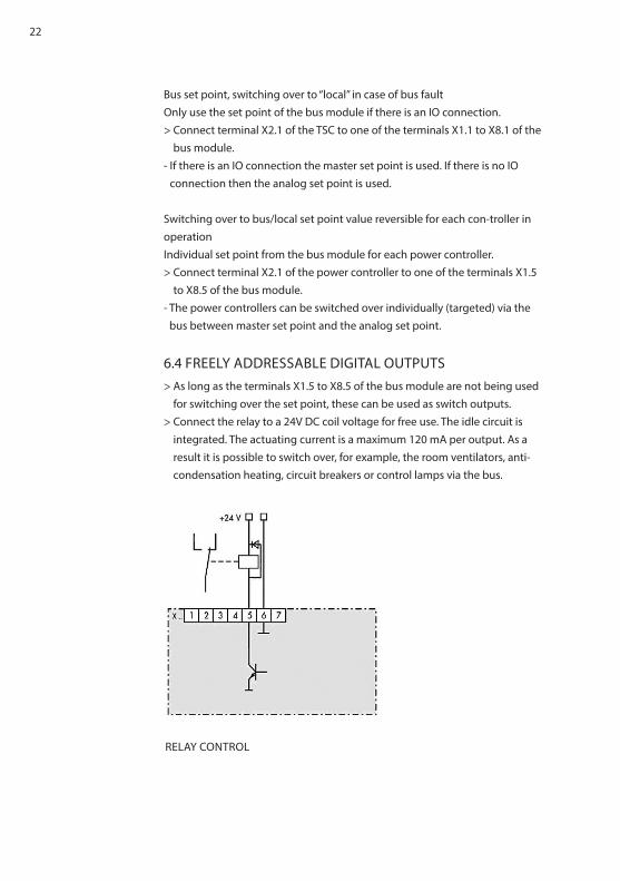
2.2 ACCIDENT PREVENTION RULES
DANGERNot adhering to the safety requirements in the operating instructions ofthe power controllers being used can lead to danger of injury/dangerof damaging the device or system.> Adhere to all safety requirements in the chapter “Safety” of theoperating instructions of the power controllers being used.
DANGER
ELECTRIC CURRENTRisk of injury from current carrying parts/danger of damaging the bus mo-dule.• Never operate the device without the covering.• Undertake adjustments and wiring only in electrically isolated status.
CAUTION
RISK OF DAMAGE OF THE BUS MODULEThe current rating at terminal X1.5 up to X8.5 should not be above 120mA.Please, check the connection data of the upstream relay.

14
NOTE
COMMUNICATION ERRORSTo avoid communication errors, please mind the following:• Use shielded cable.• Conduct grounding at the bus module (X1.7 up to X8.7). Do not ground in
addition at the power controller.
2.3 QUALIFIED PERSONNELOnly qualified electro-technical personnel who are familiar with the pertinent safety and installation regulations may perform the following:• Transport• Installation• Connection• Commissioning• Maintenance• Testing
These operating instructions must be read carefully by all persons working with or on the equipment prior to installation and initial start-up.
2.4 OPERATOR REQUIREMENTSThe person responsible for the system must ensure that:• The safety regulations and operating instructions are available and are
observed.• The operating conditions and restrictions resulting from the technical data
are observed.• The safety devices are used.• Should abnormal voltages, noises, increased temperatures, vibration or
similar occur, the device is immediately to put out of operation and the maintenance personnel is informed.
• The accident prevention regulations valid in the respective country of use and the general safety regulations are observed.
• All safety devices (covers, warning signs etc.) are present, in perfect condi-tion and are used correctly.
• The national and regional safety regulations are observed.• The personnel have access to the operating instructions and safety regulati-
ons at all times.

15
2.5 INTENDED USE
CAUTION
The intended use of the Modbus TCP Bus Module is to operate as an bus module of Thyro-A and Thyro-AX power controller, Thyro-S power switch, Thyro-Step Controller, Thyro-Measurement Unit and Thyro-Power Manager. The device may only be used for the purpose for which it was intended as persons may otherwise be exposed to dangers (e.g. electric shock, burns) and plants also (e.g. overload).
Any unauthorized reconstructions and modification to the unit, use of spare and exchange parts not approved by Advanced Energy as well as any other use of the unit is not allowed.These operating instructions contain all information required by specialists for use of the bus module. Additional information and hints for unqualified persons and for use of the unit outside of industrial installations are not contained in these operating instructions.The warranty obligation of the manufacturer applies only if these operating instructions are observed. The device is a component that cannot operate alone. Project planning must account for the proper use of the device.
2.6 LIABILITYIn case of use of Modbus TCP bus module for applications not provided for by the manufacturer, no liability is assumed. The responsibility for required measures to avoid hazards to persons and property is borne by the operator respectively the user. In case of complaints, please immediately notify us stating:• type name• production number• objection• duration of use• ambient conditions• operating mode

16
3. REMARKS ON THE PRESENT OPERATING INSTRUCTIONS
3.1 VALIDITYThese operating instructions refer to latest technical specification of Modbus TCP bus module at the time of publication and are for information purpose only. Every effort has been taken to ensure the accuracy of this specification, however, in order to maintain our technological lead and for product en-hancement, Advanced Energy is continually improving their products which could, without notice, result in amendments or omissions to this specification. Advanced Energy cannot accept responsibility for damage, injury, loss or expenses resulting therefrom.The operating instructions serve only in conjunction with and as an addition to the operating instructions of the Advanced Energy devices indicated on the cover page in the versions of the types indicated on the covering page. The sa-fety instructions contained therein are to be observed in particular. If you have not got any available operating instructions of Thyro-A, Thyro-AX, Thyro-S, Thyro-Step Controller, Thyro-Measurement Unit and/or Thyro-Power Manager, please contact your supplier immediately.
3.2 HANDLINGThese operating instructions for Modbus TCP bus module are organized in a way that all work required for commissioning, maintenance and repair may be performed by corresponding specialist personnel. If hazards to personnel and property cannot be excluded for certain work, then this work is marked using certain icons. The meaning of these icons may be found in the prior chapter safety regulations.
3.3 WARRANTYCustomer shall provide written particulars, enclosing the delivery note, within 8 working days to Advanced Energy on becoming aware of any defects in the goods during the warranty period and shall use its best endeavors to provide Advanced Energy with all necessary access, facilities and information to ena-ble Advanced Energy to ascertain or verify the nature and cause of the defect and carry out its warranty obligations.If goods are found not to be defective or if any defect is attributable to customer’s design or material in operation of the goods, Advanced Energy will levy a testing charge and where relevant will return the goods to Cus-

17
tomer at customer’s expense, and shall be entitled to payment in advance if the whole testing and transport charge before such return. Advanced Energy accepts no liability for defects caused by the customer’s design or installation of the goods; or if the goods have been modified or repaired otherwise than as authorized in writing by Advanced Energy; or if the defect arises because of the fitting of the goods to unsuitable equipment. Advanced Energy will cancel all possible obligations incurred by Advanced Energy and its dealers, such as warranty commitments, service agreements, etc., without prior notice if other than original Advanced Energy spare parts or spare parts purchased from Advanced Energy are used for maintenance or repair.
3.4 COPYRIGHTNo part of these operating instructions may be transmitted, reproduced and/or copied by any electronic or mechanical means without the express prior written permission of Advanced Energy.© Copyright Advanced Energy Industries GmbH 2014.All rights reserved.
3.5 COPYRIGHT NOTICEThyro-™, Thyro-S™, Thyro-A™, Thyro-AX™ are registered trademarks of Advan-ced Energy Industries GmbH. All other company and product names are (registered) trademarks of the respective owners.

18
4. CONTACT INFORMATION
4.1 TECHNICAL QUERIESDo you have any technical queries regarding the subjects dealt with inthese operating instructions?If so, please get in touch with our team for power controllers:Phone: +49 (0) 2902 763-520Phone: +49 (0) 2902 763-290
4.2 COMMERCIAL QUERIESDo you have any commercial queries on power controllers?If so, please get in touch with our team for power controllers.Phone: +49 (0) 2902 763-558
4.3 SERVICEAdvanced Energy Industries GmbHBranch Office Warstein-BeleckeEmil-Siepmann-Straße 32D-59581 WarsteinPhone: +49 (0) 2902 763-0E-Mail: [email protected]
4.4 INTERNETFurther information on our company or our products can be found on the Internet under: http://www.advanced-energy.com

19
5. INTRODUCTION
5.1 GENERALThe Ethernet bus module (in the following indicated as “the unit”) can con-nect up to 8 power controller modules of type Thyro-A, Thyro-AX, Thyro-S, Thyro-Power Manager, Thyro-Step Controller and Thyro-Measurement Unit in any desired order with a master.Several bus modules can be used on one system.The power supply of the bus module comes from an external 24V DC voltage source (150mA), which is to be fed in (reverse polarity protected) at X11.1 (+) and X11.2 (ground). Several modules can be operated from one power supply.The ground connection at terminal X11.3 should be as short as possible for EMC reasons.
5.2 SPECIAL FEATURES• The Ethernet bus module connects the modules (power controllers) to diffe-
rent Ethernet bus systems. By setting the “Protocol” switch to 1, the Ethernet bus module becomes an Modbus TCP IO-device.
• When position 9 „Set all default“ is active the bus module will be reset to factory defaults for settings and address.
• Function control via LED• 8 free application outputs X1 to X8 on terminal 5• C-rail assembly• When the bus module is linked to Thyro-AX, please be aware that data trans-
fer is the same as for Thyro-A whereas special features or other additional parameters are excluded from this.
5.3 TYPE DESIGNATIONThe order number of the Ethernet bus module Modbus TCP is 2000 000 846

20
6. FUNCTIONS
6.1 PROCESSING THE SET POINT Thyro-SOnly local set points, no bus set pointSwitching signal (24V DC) at the control terminal X22.1 of the Thyro-S.> No wiring of the terminal point X22.4 at the power controller- The bus module is fully functional. The analog signal from the control termi-
nal X22.1 is used as set point (on/off).
Set point from the bus module (X22.3), no local set point> Connect the ground to terminal X22.4 of the power controller.- The master set point of the bus module is used. For this purpose the set
point is interpreted as the operating mode (see Tab. Interpretation of master set point for Thyro-S).
Bus set point, switching over to “local” in case of bus faultOnly use the set point of the bus module if there is an IO connection.> Connect terminal X22.4 of the power controller to one of the terminals X1.1
to X8.1 of the bus module.- If there is an IO connection the master set point is used. If not then the ana-
log signal from the control terminal X22.1 is used as set point (on/off).
Switching over to bus/local set point reversible for each controller in operationIndividual set point by bus module for each power controller.> Connect terminal X22.4 of the power controller to one of the terminals X1.5
to X8.5 of the bus module.- The power controllers can be switched over individually (targeted) via the
bus between master set point and terminal X22.1.
6.2 PROCESSING THE SET POINT Thyro-A/Thyro-AXOnly local set points, no bus set point:Analog input at control terminal X2.4 of Thyro-A/Thyro-AX> Do not connect anything to terminal X22.1 of the power controller.- The bus module is fully functional. The analog signal from the control termi-nal X2.4 is used as set point (on/off).
Set point from the bus module (X22.3), no local set point:

21
> Connect the ground to terminal X22.1 of the power controller.- The master set point of the bus module is used.
Bus set point, switching over to “local” in case of bus fault:Only use the set point of the bus module if there is an IO connection.> Connection between X22.1 Thyro-A and bus module X1.1 to X8.1During normal operation, the set point is digital.If an error is detected in the bus module or Ethernet IP communications, then the bus module will automatically float the bus module, X1.1 output.This causes the Thyro-A, X22.1 input to go high and switches to analog set point for Thyro-A (switches to 4-20mA or potentiometer control).For further details: Chapter 17. Connection diagrams Thyro-A / Thyro-AX, Fig.2
- If there is an IO connection the master set point is used. If there is no IOconnection then the analog signal from the control terminal X2.4 is used asset point.
Switching over to bus / local set point reversible for each controller in opera-tion:Individual set point from the bus module for each power controller.> Connection between X22.1 Thyro-A and bus module X1.5 to X8.5 During normal operation, the set point is analog (bit set to 0)If the bit is set to 1 then the Thyro-A set point is switched to digital.If an error is detected in the bus module or Ethernet IP communications, then the bus module will automatically float the bus module, X1.5 output.For further details: Chapter 17. Connection diagrams Thyro-A / Thyro-AX, Fig.2
- The power controllers can be switched over individually (targeted) via thebus between master set point and terminal X2.4.
6.3 PROCESSING THE SET POINT Thyro-STEP CONTROLLER
Only local set points, no bus set pointAnalog input (24V DC) at control terminal X6.1 or X6.4 (depending on X6.7) of the TSC> Do not connect anything to terminal X2.1 of the power controller.- The bus module is fully functional. The analog signal from the control termi-
nal X6.1 or X6.4 is used as a set point.
Set point from the bus module (X22.3), no local set point> Connect the ground to terminal X2.1 of the TSC.- The master set point of the Ethernet bus module is used.
22
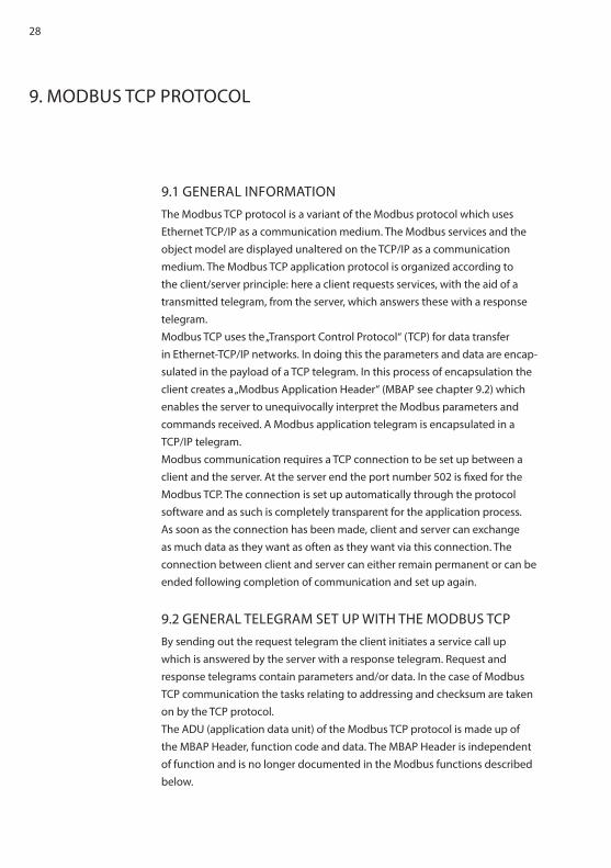
RELAY CONTROL
Bus set point, switching over to “local” in case of bus faultOnly use the set point of the bus module if there is an IO connection.> Connect terminal X2.1 of the TSC to one of the terminals X1.1 to X8.1 of the
bus module.- If there is an IO connection the master set point is used. If there is no IO
connection then the analog set point is used.
Switching over to bus/local set point value reversible for each con-troller in operationIndividual set point from the bus module for each power controller.> Connect terminal X2.1 of the power controller to one of the terminals X1.5
to X8.5 of the bus module.- The power controllers can be switched over individually (targeted) via the
bus between master set point and the analog set point.
6.4 FREELY ADDRESSABLE DIGITAL OUTPUTS> As long as the terminals X1.5 to X8.5 of the bus module are not being used
for switching over the set point, these can be used as switch outputs.> Connect the relay to a 24V DC coil voltage for free use. The idle circuit is
integrated. The actuating current is a maximum 120 mA per output. As a result it is possible to switch over, for example, the room ventilators, anti-condensation heating, circuit breakers or control lamps via the bus.

23
7. INSTALLATION
DANGER
DANGERS DURING INSTALLATIONRisk of injury/Risk of damage to the device or system.Observe all safety regulations in the chapter “Safety”.
7.1 CONNECTION TERMINALS (OVERVIEW)
TERMINAL DESCRIPTION
X11 .1 24V (+)
.2 24V (ground)
.3 grounding, carry out as short as possible
X1 to X8 .1 jointly reversible ground potential
.2 RxD
.3 TxD
.4 ground
.5 separately reversible ground potential
.6 ground
.7 ground potential for shield connection
TAB. 1 CONNECTING TERMINALS (OVERVIEW)
7.2 CONNECTING A 24 V POWER SUPPLY> Switch off the main power supply including the external 24V power source
and make sure these cannot be accidentally switched back on again.> Connect the external 24V voltage supply (150 mA) to X11.1 (+) and X11.2 (-)
(reverse polarity protection).> Ground the X11.3 terminal by a route being as short as possible (for EMC
reasons).

24
REMARK
24V DC POWER SOURCESeveral bus modules can be operated with one power supply.> In cases of SELV (safety extra low voltages) do not ground the 24V power
source.
7.3 CONNECTING THE POWER CONTROLLER TO X1-X8> Switch off the main power supply including the external 24V power source
and make sure these cannot accidentally be switched back on again.> Connect the interfaces X1 to X8 of the bus module to the system interfaces
of the power controller (shielded four-wire cable)
ATTENTIONTo control all parameters by Modbus TCP it is recommended to close the Thyro-A/Thyro-AX switches S1.3, S1.4, S1.5 (Thyro-Tool Mode).
7.4 CONNECTING THE ETHERNET BUS MODULE TO THE MASTER
The Ethernet Bus Module has two Ethernet ports which are equipped with a switch functionality which allows a line topology to be constructed.A standard patch cable is required for connecting with a switch. For a direct connection (line topology) a cross-over cable is required.

25
8. SETTINGS
8.1 SETTING THE PROTOCOLThe Ethernet Bus Module supports various real time Ethernet bus systems. The desired system can be selected using the rotary switch “Protocol”. For Modbus TCP this needs to be set to 1.
8.2 SETTING THE NUMBER OF SLOTSThe number of devices, which are connected to the Ethernet Bus Module, is set with the rotary switch “Slots”. After switching on, the Ethernet Bus Module reads all the parameters of the device. Following this it starts communicating.
REMARKIf the number of devices which has been set with the rotary switch “Slots” is higher than actual number of connected device, then the FAULT LED flashes red and no communication takes place. The units are to connected without gaps starting from Slot 1.
ATTENTIONTo change the number of slots when switched on, the switch “Slots” must first be turned to 0. Communication with the master is then interrupted. Fol-lowing this the desired number can be set. After leaving the position 0 there is about 2 seconds time for this.
8.3 SETTING THE IP ADDRESSThe IP address of the bus module can be set via a DHCP server. The IP address is stored in the device as nonvolatile. In Power-On mode the device waits for the IP address to be allocated from a DHCP server. If a DHCP server is not found within 136 seconds, the device starts up with the saved address.

26
8.4 CONFIGURATION AND LED DISPLAYSFor the error analysis there are several LEDs on the plug-in card. They give information about the status of the application and the bus system.The two-colored (green/red) module status SYS LED shows if the device is supplied with power and whether it functions properly. In the startup phase the red SYS LED flashes briefly (about 1 sec).The two-colored (green/red) network status LED shows the status of the communication connection.
LED COLOR STATUS MEANING
SYS(Module Status)
Green OFF Power Off, Error (see SYS Red)
ON Operating system running
Red OFF Failure of power supply
Flashing with 1 Hz
Error in boot process
ON Waiting for boot process (check switch position „Protocol“)
COM0 (NS Network Status)
Green OFF Failure of power supply
Flashing with 1 Hz
IP address not configured
Flashing with 5 Hz
IP address configuration, no data exchange
ON The device is exchanging data with the controller
Red Flashing Timeout of the connection
COM1 - - Not used
Fault Red ON Hardware error
TAB. 2 OPERATING DISPLAY ON THE BUS MODULE
The status of Ethernet communication is shown by the RJ 45 integrated LED:
LED COLOR STATUS MEANING
Link Green On There is an Ethernet connection
Activity Yellow On Data are being exchanged via Ethernet
TAB. 3 STATUS LED OF ETHERNET PORTS 1&2

27
1 Terminal X1 10 Terminal X112 Terminal X2 11 SYS LED3 Terminal X3 12 COM0 (NS) LED4 Terminal X4 13 COM1 LED5 Terminal X5 14 Fault LED 6 Terminal X6 15 Switch Slots7 Terminal X7 16 Switch Protocol8 Terminal X8 9 Ethernet Port
FIG. 1 CONFIGURATION AND LED DISPLAYS
28
9. MODBUS TCP PROTOCOL
9.1 GENERAL INFORMATIONThe Modbus TCP protocol is a variant of the Modbus protocol which uses Ethernet TCP/IP as a communication medium. The Modbus services and the object model are displayed unaltered on the TCP/IP as a communication medium. The Modbus TCP application protocol is organized according to the client/server principle: here a client requests services, with the aid of a transmitted telegram, from the server, which answers these with a response telegram.Modbus TCP uses the „Transport Control Protocol“ (TCP) for data transfer in Ethernet-TCP/IP networks. In doing this the parameters and data are encap-sulated in the payload of a TCP telegram. In this process of encapsulation the client creates a „Modbus Application Header“ (MBAP see chapter 9.2) which enables the server to unequivocally interpret the Modbus parameters and commands received. A Modbus application telegram is encapsulated in a TCP/IP telegram.Modbus communication requires a TCP connection to be set up between a client and the server. At the server end the port number 502 is fixed for the Modbus TCP. The connection is set up automatically through the protocol software and as such is completely transparent for the application process. As soon as the connection has been made, client and server can exchange as much data as they want as often as they want via this connection. The connection between client and server can either remain permanent or can be ended following completion of communication and set up again.
9.2 GENERAL TELEGRAM SET UP WITH THE MODBUS TCPBy sending out the request telegram the client initiates a service call up which is answered by the server with a response telegram. Request and response telegrams contain parameters and/or data. In the case of Modbus TCP communication the tasks relating to addressing and checksum are taken on by the TCP protocol.The ADU (application data unit) of the Modbus TCP protocol is made up of the MBAP Header, function code and data. The MBAP Header is independent of function and is no longer documented in the Modbus functions described below.

29
GENERAL MODBUS TCP TELEGRAM SET UP (ADU)
MBAP Header Function code Data
7 bytes 1 byte x- bytes (value range 1.. 252 byte)
MBAP Header (Modbus Application Protocol Header)Byte 0,1: Transaction Identifier Byte 2,3: Protocol identifier 0 for Modbus TCP protocol Byte 4,5: Number of consecutive bytes (High-Byte, Low-Byte)Byte 6: Unit identifier (Unit Identifier Remote)
Function codeByte 7: Modbus function code see chapter 9.5
DataByte 8..n: The data range corresponds with that of the standard Modbus
protocol. The CRC checksum, however, is no longer required as it is implemented at the TCP/IP protocol level.
Both the request and the response telegrams always contain a function code (length: 1 byte) on which the further set up of the subsequent data depends.
9.3 HANDLING EXCEPTIONSIn the case of an exception the device (server) sends an exception response and the request telegram (the request in question) is discarded. The response telegram in the case of an exception contains the function code received, however, here the highest value bit (MSB) is set to display an exception.
EXCEPTION FUNCTION CODE EXCEPTION CODE
1 byte 1 byte
Function code + 0x80 01 or 02 or 03 or 04
In the Exception code one of the following exception types is entered:
1. ILLEGAL FUNCTION (0x01)The function code received in the request is not supported by the device.

30
2. ILLEGAL DATA ADDRESS (0x02)The register address does not exist. It must be smaller than 624. In the case of „Read Holding Registers“ and „Preset Multiple Regs“ requests the address is made up of the start address of the register and the number of registers. So that means: register + number < 624. The valid addresses are listed in the tables below.
3. ILLEGAL REGISTER QUANTITY (0x03)The number of registers is invalid, which means that it is outside the range of 1 to 125.
4. REQUEST PROCESSING (0x04)A device exception occurred whilst accessing the parameter in the applica-tion (e.g. parameter is write-protected, invalid value, incorrect index/incorrect slot in the application).
9.4 MODBUS DATA TYPESModbus distinguishes between the following data types: byte (8 bit) and re-gister (16 bit). A register corresponds to two bytes, whereby the byte with the higher value is transferred as the first data unit each time. As such Modbus uses the so-called Big-Endian format for the display of addresses and data.Extended data types such as 32 bit integer and 32 bit float are transmitted as 2 consecutive 16 bit registers.In the bus module the information from the device is displayed in the fol-lowing register types (16 bit).
DATA TYPE LENGTH VALUE RANGE
ACCESS DESCRIPTION
Input Register
16 bit 0.. 65536 r Data made available by the device as Read Only
Holding Register
16 bit 0.. 65536 r/wData can be altered from the application

31
The data are addressed using addresses in the range from 0x0000 to 0xFFFF. The smallest data unit which can be read is a register (16 bits). The number of registers which can be read can vary from 1 to maximum 125 (0x7D). The following data types are supported by the bus module:
DATA TYPE NAME DESCRIPTION RANGE
UINT Unsigned integer 0 to 65535
UDINT Unsigned double integer 0 to 231-1
Float32 Float
WORD Bit-string 16 bits
DWORD Bit-string 32 bits
9.5 FUNCTIONSThe following functions from the range of “Public Function Codes“ are supported:
FUNCTION CODE DATA TYPE
ACCESS DESCRIPTION
Read Hol-ding Register
0x03 Holding Register
Read Reads one or more Holding Registers from the device
Read Input Register
0x04 Input Register
Read Reads one or more Input Registers form the device
Preset Single Re-gister
0x06 Holding Register
Write Alters a register in the device.
Preset Multiple Regs
0x10 Holding Register
Write Alters multiple registers in the device
TAB. 4 MODBUS FUNCTIONS

32
9.5.1 READ HOLDING REGISTERS (0X03) With this telegram the client can read out one or multiple registers from the device (function code 0x03), whereby the registers must be consecutive.
Request:
FUNCTION CODE START ADDRESS OF THE REGISTERS
NUMBER OF REGISTERS
1 byte 2 byte 2 byte
0x03 0x0000 to 0xFFFF 1..125
Response:
FUNCTION CODE NUMBER OF BYTES DATA (CONTENT OF REGIS-TERS)
1 byte 1 byte 2 * number of registers byte
0x03 2 * number of registers 0x0000 to 0xFFFF
Exception Responses:
EXCEPTION FUNCTION CODE EXCEPTION CODE
1 byte 1 byte
0x83 01 or 02 or 03 or 04
9.5.2 READ INPUT REGISTERS (0X04)With this telegram the client can read out one or multiple registers from the device (function code 0x04), whereby the registers must be consecutive.
Request:
FUNCTION CODE START ADDRESS OF THE REGISTERS
NUMBER OF INPUT REGIS-TERS
1 byte 2 byte 2 byte
0x04 0x0000 to 0xFFFF 1..125
Response:

33
FUNCTION CODE NUMBER OF BYTES DATA (CONTENT OF REGIS-TERS)
1 byte 1 byte 2 * number of registers byte
0x04 2 * number of registers 0x0000 to 0xFFFF
Exception Responses:
EXCEPTION RESPONSE CODE EXCEPTION CODE
1 byte 1 byte
0x84 01 or 02 or 03 or 04
9.5.3 PRESET SINGLE REGISTER (0X06) With this telegram the client can alter a register in the device (function code 0x06). The response in an exception free case is identical to the request.
Request:
FUNCTION CODE ADDRESS OF THE REGISTER
DATA
1 byte 2 byte 2 byte
0x06 0x0000 to 0xFFFF 0x0000 to 0xFFFF
Response:
FUNCTION CODE ADDRESS OF THE REGISTER
DATA
1 byte 2 byte 2 byte
0x06 0x0000 to 0xFFFF 0x0000 to 0xFFFF
Exception Responses:
EXCEPTION FUNCTION CODE EXCEPTION CODE
1 byte 1 byte
0x86 01 or 02 or 03 or 04

34
9.5.4 PRESET MULTIPLE REGS (0X10) With this telegram the client can alter one or multiple registers in the device (function code 0x10), whereby the registers must be consecutive.
Request:
FUNCTION CODE
START ADDRESS OF THE REGISTERS
NUMBER OF REGISTERS
NUMBER OF BYTES
DATA
1 byte 2 byte 2 byte 1 byte2 * number of registers byte
0x10 0x0000 to 0xFFFF 1..1232 * number of registers
0x0000 to 0xFFFF
Response:
FUNCTION CODE START ADDRESS OF THE REGISTERS
DATA
1 byte 2 byte 2 byte
0x10 0x0000 to 0xFFFF 0x0000 to 0xFFFF
Exception Responses:
EXCEPTION FUNCTION CODE EXCEPTION CODE
1 byte 1 byte
0x90 01 or 02 or 03 or 04

35
10. REGISTER CONFIGURATION (PARAMETER MAPPING ON MODBUS TCP)
The bus module contains max. of 8 slots which can be configured by the mo-dules. For the cyclic and acyclic data a separate address range is used for each slot starting from 0X1000 which is reserved according to configured module. The data of the bus module represent the slot no. 0. The register are therefore divided in the following parts:
RANGE ADDRESS RANGE OF THE REGISTER
Bus module Slot 0 0x0000 to 0x0FFF
Module (Controller) in Slot 1 0x1000 to 0x1FFF
Slot 2 0x2000 to 0x2FFF
Slot 3 0x3000 to 0x3FFF
Slot 4 0x4000 to 0x4FFF
Slot 5 0x5000 to 0x5FFF
Slot 6 0x6000 to 0x6FFF
Slot 7 0x7000 to 0x7FFF
Slot 8 0x8000 to 0x8FFF
TAB. 5 REGISTER CONFIGURATION OF THE BUS MODULE FOR MODBUS TCP
The parameters are collated in the following groups and as such can be read or written individually or together:• Set points, • actual values,• acyclical parameter.
The offset of each group is defined as the following:• Offset set points 0x0• Offset actual values 0x10• Offset acyclic parameters 0x100
The Offset of each register (16 bit) within the following tables is in accordance to the Offset at the beginning of the related area. The parameter of the bus module is in accordance to slot no. 0.

36
The address of the related register is calculated in the following way:• Register address set point = Slot-Nr.*1000 + 0x0 + Offset set point• Register address
actual value = Slot-Nr.*1000 + 0x10 + Offset actual value
• Register address acyclic parameters = Slot-Nr.*1000 + 0x100 + Offset parameter
The set point of each module can be max. of 14 bytes long. Therefore 16 bytes per slot are reserved for the set points.The actual values per module can be max. of 54 bytes long. Therefore 240 bytes per slot are reserved for actual values.The acyclic parameters per module can be max. of 128 bytes long. Therefore 240 bytes per slot are reserved for acyclic parameters.Accessing address ranges outside of the groups invokes the exception „Illegal Data Address“.

37
11. DATA OF THE BUS MODULE
The address range 0x0000-0x0FFF consists of the digital outputs and the configuration parameters of the bus module.
11.1 CYCLIC DATA (INPUT AND OUTPUT DATA) OF THE BUS MODULE
The digital outputs are positioned in the addresses 0x0000-0x0001.
ADDRESS BYTE DATA TYPE
NAME VALUE RANGE
R/W
0x0000 2 UINT Digitale Ausgänge
R/W
TAB. 6 INPUT AND OUTPUT DATA OF THE BUS MODULE
11.2 ACYCLIC DATA: BUS MODULE The configuration parameter show the current configuration of each slot with modules and have the address range from 0x100 to 0x107. The device types, which can be connected to the bus module, are indicated as follows:
MODULTYP ID
Thyro-S 1S H1 0x11
HRL1 0x12
Thyro-A 1A/Thyro-AX 1A H1 0x41
HRL1/HRL2 0x42
HRLP1/ HRLP2 0x43
Thyro-A 2A/Thyro-AX 2A H1 0x51
HRL1/HRL2 0x52
HRLP1/ HRLP2 0x53
Thyro-A 3A/Thyro-AX 3A H1 0x61
HRL1/HRL2 0x62
HRLP1/ HRLP2 0x63

38
Thyro-A 1A C01 0x71
C02 0x72
C03 0x73
C05 0x75
C07 0x77
Thyro-Power Manager (TPM) TPM_AUTO 0x81
TPM_MAN 0x82
TPM_TSC 0x87
TPM_TIO 0x8D
TPM_TMU 0x8E
Thyro-Step Controller (TSC) TSC_TSC 0x97
TSC_TIO 0x9D
TSC_TMU 0x9E
Thyro-Measurement Unit (TMU) TMU_TIO 0xAD
TMU_TMU 0xAE
TAB. 7 INDICATION OF MODULE TYPES
ADDRESS BYTE DATA TYPE NAME VALUE RANGE
R/W
0x0100 2 UINT Configuration slot 1 0x11-0xFF R
0x0101 2 UINT Configuration slot 2 0x11-0xFF R
0x0102 2 UINT Configuration slot 3 0x11-0xFF R
0x0103 2 UINT Configuration slot 4 0x11-0xFF R
0x0104 2 UINT Configuration slot 5 0x11-0xFF R
0x0105 2 UINT Configuration slot 6 0x11-0xFF R
0x0106 2 UINT Configuration slot 7 0x11-0xFF R
0x0107 2 UINT Configuration slot 8 0x11-0xFF R
0x0108 2 UINT MODULE_POS_ AVERAGE
R/W
0x0109 2 UINT MODULE_POS_ ERROR_CONFIG
R/W
TAB. 8 BUS MODULE PARAMETERS

39
12. DATA OF THE MODULES (CONTROLLER)
Each module type includes one group of set points and actual values which are cyclic in groups or as such can be read or written individually. The acyclic parameters are used for configuration and are usually read or written indivi-dually.
12.1 CYCLIC DATA OF THE MODULESThe input/output data for Thyro-S, Thyro-A and Thyro-AX correspond in accordance to the configured modules and for TPM, TSC, TMU in accordance to the operating mode. The following table indicates the available input and output data for the respective modules.Thyro-S 1S..H1, 1S..HRL1,Thyro-A 1A..H1, 1A..HRL1, 1A..HRLP1, 2A..H1, 2A..HRL1, 2A..HRLP1 3A..H1, 3A..HRL1, 3A..HRLP1, 1A..C01, 1A..C02, 1A..C03, 1A..C05, 1A..C07Thyro-AX 1A..HRL2, 1A..HRLP2 2A..HRL2, 2A..HRLP2 3A..HRL2, 3A..HRLP2TPM, TSP, TMU: TPM automatic mode and manual mode, TSC mode,TIO mode, TMU mode
12.1.1 CYCLIC DATA (INPUT AND OUTPUT DATA)
WITH Thyro-SThe Thyro-S interprets the set point as operating mode.
SET POINT (MASTER) STATUS (RETURN VALUE )
(TOTAL SET POINT)
0 to 409 = OFF 0 =
410 to 1091 1/5 819
1092 to 1706 = 1/3 1365 =
1707 to 3071 1/2 2047
3072 to 4096 = ON 4096
TAB. 9 INTERPRETATION OF THE MASTER SET POINT FOR Thyro-S

40
12.1.2 CYCLIC DATA (INPUT AND OUTPUT DATA) WITH Thyro-S 1S..H1
12.1.3 CYCLIC DATA (INPUT AND OUTPUT DATA) WITH Thyro-S 1S..HRL1
OFFSET INPUT DATA,ACTUAL VALUES
SYMBOL DATATYPE
SIZE (BYTE)
UNIT
0x0000 Load voltage L1 AD_IW_U_EFF_LSB_1 Float32 4 [V]
0x0002 Mains voltage L1 AD_IW_MAIN_LSB_1 UINT 2 [V]
0x0003 Total setpoint AD_SW_SUMME UINT 2 4096=100%
0x0004 Fault (see Tab. 12) AD_IW_STOER UINT 2 -
0x0005 Status (see Tab. 13) AD_IW_STATUS UINT 2 -
OFFSET OUTPUT DATA, SET POINTS
SYMBOL DATATYPE
SIZE (BYTE)
UNIT
0x0000 Master setpoint AD_SW_MASTER UINT 2 4096=100%
TAB. 10 INPUT AND OUTPUT DATA WITH Thyro-S 1S..HRL1
OFFSET INPUT DATA,ACTUAL VALUES
SYMBOL DATATYPE
SIZE (BYTE)
UNIT
0x0000 Load voltage L1 AD_IW_U_EFF_LSB_1 Float32 4 [V]
0x0002 Load current L1 AD_IW_I_EFF_LSB_1 Float32 4 [A]
0x0004 Mains voltage L1 AD_IW_MAIN_LSB_1 UINT 2 [V]
0x0005 Total setpoint AD_SW_SUMME UINT 2 4096=100%
0x0006 Fault (see Tab. 12) AD_IW_STOER UINT 2 -
0x0007 Status (see Tab. 13) AD_IW_STATUS UINT 2 -
OFFSET OUTPUT DATA, SET POINTS
SYMBOL DATATYPE
SIZE (BYTE)
UNIT
0x0000 Master setpoint AD_SW_MASTER UINT 2 4096=100%
TAB. 11 INPUT AND OUTPUT DATA WITH Thyro-S 1S..HRL1

41
DESCRIPTION BIT LEDS RELAY
Frequency measurement outside of 47 Hz to 63 Hz
Bit 0 Test LED flashing slowly released
SYNC error, no zero-crossing within the gate Bit 1 Test LED flashing slowly released
Temperature monitoring triggered Bit 2 Load fault flashing slowly released
Load fault Bit 3 Load fault on released
Flash values invalid Bit 4 Test LED and Load fault LED flas-hing simultaneously quickly
released
Mains undervoltage (<AD_P_SPG_MIN) Bit 5 Load fault LED and test LED on released
Mains overvoltage (>AD_P_SPG_MAX) Bit 6 None energized
TAB. 12 Thyro-S FAULTS
DESCRIPTION BIT LEDS RELAY
Pulse inhib active (bridge X2.1-X2.2 open) Bit 0 None released
Mains frequency is 60Hz Bit 2 None released
Relay status(0=relay off/1=relay on)
Bit 8 None released
Device switched off Bit 9 -- energized
Wrong device Bit 10 -- ----
Bus module active(0=no bus module/1=bus module active)
Bit 11 None ----
Thyristor short-circuit Bit 14 Test LED and Load fault LED flas-hing alternately slowly
----
TAB. 13 Thyro-S STATUS

42
12.1.4 CYCLIC DATA (INPUT AND OUTPUT DATA) WITH Thyro-A 1A..H1
12.1.5 CYCLIC DATA (INPUT AND OUTPUT DATA) WITH Thyro-A 1A..HRL1/Thyro-AX 1A..HRL2
OFFSET INPUT DATA,ACTUAL VALUES
SYMBOL DATATYPE
SIZE (BYTE)
UNIT
0x0000 Load voltage L1 AD_IW_U_EFF_LSB_1 Float32 4 [V]
0x0002 Mains voltage L1 AD_IW_MAIN_LSB_1 UINT 2 [V]
0x0003 Switch-on time TS AD_IW_TS UINT 2 [period]
0x0004 Switch-on angle alpha AD_IW_ALPHA UINT 2 [0.01 °el]
0x0005 Total setpoint AD_SW_SUMME UINT 2 4096=100%
0x0006 Fault (see Tab. 23) AD_IW_STOER UINT 2 -
0x0007 Status (see Tab. 24) AD_IW_STATUS UINT 2 -
OFFSET OUTPUT DATA, SET POINTS
SYMBOL DATATYPE
SIZE (BYTE)
UNIT
0x0000 Master setpoint AD_SW_MASTER UINT 2 4096=100%
TAB. 14 INPUT AND OUTPUT DATA WITH Thyro-A 1A..H1
OFFSET INPUT DATA,ACTUAL VALUES
SYMBOL DATATYPE
SIZE (BYTE)
UNIT
0x0000 Load voltage L1 AD_IW_U_EFF_LSB_1 Float32 4 [V]
0x0002 Load current L1 AD_IW_I_EFF_LSB_1 Float32 4 [A]
0x0004 Mains voltage L1 AD_IW_MAIN_LSB_1 UINT 2 [V]
0x0005 Switch-on time TS AD_IW_TS UINT 2 [period]
0x0006 Switch-on angle alpha AD_IW_ALPHA UINT 2 [0.01 °el]
0x0007 Total setpoint AD_SW_SUMME UINT 2 4096=100%
0x0008 Fault (see Tab. 23) AD_IW_STOER UINT 2 -
0x0009 Status (see Tab. 24) AD_IW_STATUS UINT 2 -
OFFSET OUTPUT DATA, SET POINTS
SYMBOL DATATYPE
SIZE (BYTE)
UNIT
0x0000 Master setpoint AD_SW_MASTER UINT 2 4096=100%
TAB. 15 INPUT AND OUTPUT DATA WITH Thyro-A 1A..HRL1/ Thyro-AX 1A..HRL2

43
12.1.6 CYCLIC DATA (INPUT AND OUTPUT DATA) WITH Thyro-A 1A..HRLP1/Thyro-AX 1A..HRLP2
OFFSET INPUT DATA,ACTUAL VALUES
SYMBOL DATATYPE
SIZE (BYTE)
UNIT
0x0000 Load voltage L1 AD_IW_U_EFF_LSB_1 Float32 4 [V]
0x0002 Load current L1 AD_IW_I_EFF_LSB_1 Float32 4 [A]
0x0004 Power L1 AD_IW_P_LSB_1 Float32 4 [W]
0x0006 Mains voltage L1 AD_IW_MAIN_LSB_1 UINT 2 [V]
0x0007 Switch-on time TS AD_IW_TS UINT 2 [period]
0x0008 Switch-on angle alpha AD_IW_ALPHA UINT 2 [0.01 °el]
0x0009 Total setpoint AD_SW_SUMME UINT 2 4096=100%
0x000A Fault (see Tab. 23) AD_IW_STOER UINT 2 -
0x000B Status (see Tab. 24) AD_IW_STATUS UINT 2 -
OFFSET OUTPUT DATA, SET POINTS
SYMBOL DATATYPE
SIZE (BYTE)
UNIT
0x0000 Master setpoint AD_SW_MASTER UINT 2 4096=100%
TAB. 16 INPUT AND OUTPUT DATA WITH Thyro-A 1A..HRLP1/ Thyro-AX 1A..HRLP2
12.1.7 CYCLIC DATA (INPUT AND OUTPUT DATA) WITH Thyro-A 2A..H1
OFFSET INPUT DATA,ACTUAL VALUES
SYMBOL DATATYPE
SIZE (BYTE)
UNIT
0x0000 Load voltage L1 AD_IW_U_EFF_LSB_1 Float32 4 [V]
0x0002 Load voltage L3 AD_IW_U_EFF_LSB_3 Float32 4 [V]
0x0004 Mains voltage L1 AD_IW_MAIN_LSB_1 UINT 2 [V]
0x0005 Mains voltage L3 AD_IW_MAIN_LSB_3 UINT 2 [V]
0x0006 Switch-on time TS AD_IW_TS UINT 2 [period]
0x0007 Total setpoint AD_SW_SUMME UINT 2 4096=100%
0x0008 Fault (see Tab. 23) AD_IW_STOER UINT 2 -
0x0009 Status (see Tab. 24) AD_IW_STATUS UINT 2 -
OFFSET OUTPUT DATA, SET POINTS
SYMBOL DATATYPE
SIZE (BYTE)
UNIT
0x0000 Master setpoint AD_SW_MASTER UINT 2 4096=100%
TAB. 17 INPUT AND OUTPUT DATA WITH Thyro-A 2A..H1

44
12.1.8 CYCLIC DATA (INPUT AND OUTPUT DATA) WITH Thyro-A 2A..HRL1/Thyro-AX 2A..HRL2
OFFSET INPUT DATA,ACTUAL VALUES
SYMBOL DATATYPE
SIZE (BYTE)
UNIT
0x0000 Load voltage L1 AD_IW_U_EFF_LSB_1 Float32 4 [V]
0x0002 Load voltage L3 AD_IW_U_EFF_LSB_3 Float32 4 [V]
0x0004 Load current L1 AD_IW_I_EFF_LSB_1 Float32 4 [A]
0x0006 Load current L2 AD_IW_I_EFF_LSB_2 Float32 4 [A]
0x0008 Load current L3 AD_IW_I_EFF_LSB_3 Float32 4 [A]
0x000A Mains voltage L1 AD_IW_MAIN_LSB_1 UINT 2 [V]
0x000B Mains voltage L3 AD_IW_MAIN_LSB_3 UINT 2 [V]
0x000C Switch-on time TS AD_IW_TS UINT 2 [period]
0x000D Total setpoint AD_SW_SUMME UINT 2 4096=100%
0x000E Fault (see Tab. 23) AD_IW_STOER UINT 2 -
0x000F Status (see Tab. 24) AD_IW_STATUS UINT 2 -
OFFSET OUTPUT DATA, SET POINTS
SYMBOL DATATYPE
SIZE (BYTE)
UNIT
0x0000 Master setpoint AD_SW_MASTER UINT 2 4096=100%
TAB. 18 INPUT AND OUTPUT DATA WITH Thyro-A 2A..HRL1/ Thyro-AX 2A..HRL2

45
12.1.9 CYCLIC DATA (INPUT AND OUTPUT DATA) WITH Thyro-A 2A..HRLP1/Thyro-AX 2A..HRLP2
OFFSET INPUT DATA,ACTUAL VALUES
SYMBOL DATATYPE
SIZE (BYTE)
UNIT
0x0000 Load voltage L1 AD_IW_U_EFF_LSB_1 Float32 4 [V]
0x0002 Load voltage L3 AD_IW_U_EFF_LSB_3 Float32 4 [V]
0x0004 Load current L1 AD_IW_I_EFF_LSB_1 Float32 4 [A]
0x0006 Load current L2 AD_IW_I_EFF_LSB_2 Float32 4 [A]
0x0008 Load current L3 AD_IW_I_EFF_LSB_3 Float32 4 [A]
0x000A Power L1 AD_IW_P_LSB_1 Float32 4 [W]
0x000C Power L3 AD_IW_P_LSB_3 Float32 4 [W]
0x000E Total power AD_IW_P_LSB_GES Float32 4 [W]
0x0010 Mains voltage L1 AD_IW_MAIN_LSB_1 UINT 2 [V]
0x0011 Mains voltage L2 AD_IW_MAIN_LSB_3 UINT 2 [V]
0x0012 Switch-on time TS AD_IW_TS UINT 2 [period]
0x0013 Total setpoint AD_SW_SUMME UINT 2 4096=100%
0x0014 Fault (see Tab. 23) AD_IW_STOER UINT 2 -
0x0015 Status (see Tab. 24) AD_IW_STATUS UINT 2 -
OFFSET OUTPUT DATA, SET POINTS
SYMBOL DATATYPE
SIZE (BYTE)
UNIT
0x0000 Master setpoint AD_SW_MASTER UINT 2 4096=100%
TAB. 19 INPUT AND OUTPUT DATA WITH Thyro-A 2A..HRLP1/ Thyro-AX 2A..HRLP2

46
12.1.10 CYCLIC DATA (INPUT AND OUTPUT DATA) WITH Thyro-A 3A..H1
OFFSET INPUT DATA,ACTUAL VALUES
SYMBOL DATATYPE
SIZE (BYTE)
UNIT
0x0000 Load voltage L1 AD_IW_U_EFF_LSB_1 Float32 4 [V]
0x0002 Load voltage L2 AD_IW_U_EFF_LSB_2 Float32 4 [V]
0x0004 Load voltage L3 AD_IW_U_EFF_LSB_3 Float32 4 [V]
0x0006 Mains voltage L1 AD_IW_MAIN_LSB_1 UINT 2 [V]
0x0007 Mains voltage L2 AD_IW_MAIN_LSB_2 UINT 2 [V]
0x0008 Mains voltage L3 AD_IW_MAIN_LSB_3 UINT 2 [V]
0x0009 Switch-on time TS AD_IW_TS UINT 2 [period]
0x000A Switch-on angle alpha AD_IW_ALPHA UINT 2 [0.01 °el]
0x000B Total setpoint AD_SW_SUMME UINT 2 4096=100%
0x000C Fault (see Tab. 23) AD_IW_STOER UINT 2 -
0x000D Status (see Tab. 24) AD_IW_STATUS UINT 2 -
OFFSET OUTPUT DATA, SET POINTS
SYMBOL DATATYPE
SIZE (BYTE)
UNIT
0x0000 Master setpoint AD_SW_MASTER UINT 2 4096=100%
TAB. 20 INPUT AND OUTPUT DATA WITH Thyro-A 3A..H1

47
12.1.11 CYCLIC DATA (INPUT AND OUTPUT DATA) WITH Thyro-A 3A..HRL1/Thyro-AX 3A..HRL2
OFFSET INPUT DATA,ACTUAL VALUES
SYMBOL DATATYPE
SIZE (BYTE)
UNIT
0x0000 Load voltage L1 AD_IW_U_EFF_LSB_1 Float32 4 [V]
0x0002 Load voltage L2 AD_IW_U_EFF_LSB_2 Float32 4 [V]
0x0004 Load voltage L3 AD_IW_U_EFF_LSB_3 Float32 4 [V]
0x0006 Load current L1 AD_IW_I_EFF_LSB_1 Float32 4 [A]
0x0008 Load current L2 AD_IW_I_EFF_LSB_2 Float32 4 [A]
0x000A Load current L3 AD_IW_I_EFF_LSB_3 Float32 4 [A]
0x000C Mains voltage L1 AD_IW_MAIN_LSB_1 UINT 2 [V]
0x000D Mains voltage L2 AD_IW_MAIN_LSB_2 UINT 2 [V]
0x000E Mains voltage L3 AD_IW_MAIN_LSB_3 UINT 2 [V]
0x000F Switch-on time TS AD_IW_TS UINT 2 [period]
0x0010 Switch-on angle alpha AD_IW_ALPHA UINT 2 [0.01 °el]
0x0011 Total setpoint AD_SW_SUMME UINT 2 4096=100%
0x0012 Fault (see Tab. 23) AD_IW_STOER UINT 2 -
0x0013 Status (see Tab. 24) AD_IW_STATUS UINT 2 -
OFFSET OUTPUT DATA, SET POINTS
SYMBOL DATATYPE
SIZE (BYTE)
UNIT
0x0000 Master setpoint AD_SW_MASTER UINT 2 4096=100%
TAB. 21 INPUT AND OUTPUT DATA WITH Thyro-A 3A..HRL1/ Thyro-AX 3A..HRL2

48
12.1.12 CYCLIC DATA (INPUT AND OUTPUT DATA) WITH Thyro-A 3A..HRLP1/Thyro-AX 3A..HRLP2
OFFSET INPUT DATA,ACTUAL VALUES
SYMBOL DATATYPE
SIZE (BYTE)
UNIT
0x0000 Load voltage L1 AD_IW_U_EFF_LSB_1 Float32 4 [V]
0x0002 Load voltage L2 AD_IW_U_EFF_LSB_2 Float32 4 [V]
0x0004 Load voltage L3 AD_IW_U_EFF_LSB_3 Float32 4 [V]
0x0006 Load current L1 AD_IW_I_EFF_LSB_1 Float32 4 [A]
0x0008 Load current L2 AD_IW_I_EFF_LSB_2 Float32 4 [A]
0x000A Load current L3 AD_IW_I_EFF_LSB_3 Float32 4 [A]
0x000C Power L1 AD_IW_P_LSB_1 Float32 4 [W]
0x000E Power L2 AD_IW_P_LSB_2 Float32 4 [W]
0x0010 Power L3 AD_IW_P_LSB_3 Float32 4 [W]
0x0012 Total power AD_IW_P_LSB_GES Float32 4 [W]
0x0014 Mains voltage L1 AD_IW_MAIN_LSB_1 UINT 2 [V]
0x0015 Mains voltage L2 AD_IW_MAIN_LSB_2 UINT 2 [V]
0x0016 Mains voltage L3 AD_IW_MAIN_LSB_3 UINT 2 [V]
0x0017 Switch-on time TS AD_IW_TS UINT 2 [period]
0x0018 Switch-on angle alpha AD_IW_ALPHA UINT 2 [0.01 °el]
0x0019 Total setpoint AD_SW_SUMME UINT 2 4096=100%
0x001A Fault (see Tab. 23) AD_IW_STOER UINT 2 -
0x001B Status (see Tab. 24) AD_IW_STATUS UINT 2 -
OFFSET OUTPUT DATA, SET POINTS
SYMBOL DATATYPE
SIZE (BYTE)
UNIT
0x0000 Master setpoint AD_SW_MASTER UINT 2 4096=100%
TAB. 22 INPUT AND OUTPUT DATA WITH Thyro-A 3A..HRLP1/ Thyro-AX 3A..HRLP2

49
DESCRIPTION BIT LEDS RELAY
Frequency measurement outside of 47 Hz to 63 Hz
Bit 0 Pulse inhibit LED flashing alternately slowly
released
SYNC error, no zero crossing within the gate
Bit 1 Pulse inhibit LED flashing alternately slowly
released
Temperature monitoring triggered Bit 2 Load fault LED flashing alternately slowly
released
Load fault Bit 3 Load fault LED on released
Flash values invalid Bit 4 Pulse inhibit LED and load fault LED flashing simultaneously quickly
released
Mains undervoltage (<AD_P_SPG_MIN) Bit 5 Pulse inhibit LED, load fault LED and test LED on
released
Mains overvoltage (>AD_P_SPG_MAX) Bit 6 None released
Master/slave fault (only with2A) Bit 8 None energized
Umin (Undervoltage limit) Bit 9 None energized
Umax (Overvoltage limit) Bit 10 None energized
Imin (Undercurrent limit) Bit 11 None energized
Imax (Overcurrent limit) Bit 12 None energized
Pmin (Low power limit) Bit 13 None energized
Pmax (High power limit) Bit 14 None energized
TAB. 23 Thyro-A/Thyro-AX FAULTS

50
DESCRIPTION BIT LEDS RELAY
Pulse inhib active (bridge X2.1-X2.2 open) Bit 0 Pulse inhibit LED on energized
Mains frequency is 60Hz Bit 2 None energized
U-limiting Bit 4 Pulse inhibit LED and Load fault LED flashing alternately slowly
energized
I-limiting Bit 5 Pulse inhibit LED and Load fault LED flashing alternately slowly
energized
P-limiting Bit 6 Pulse inhibit LED and Load fault LED flashing alternately slowly
energized
Relay status (0= Relay OFF/1= Relay ON) Bit 8 None ON/OFF
Device switched off Bit 9 -- --
Wrong device Bit 10 -- --
Bus module active(0=no bus module/1=bus module active)
Bit 11 None energized
Thyristor short-circuit Bit 14 Only with Thyro-S ----
Failure rotating field/phase(only 2A or 3A)
Bit 15 Pulse inhibit LED and test LEDflashing simultaneously slowly
energized
Imax (Overcurrent limit) - internal Bit 12 None energized
Pmin (Low power limit) - internal Bit 13 None energized
Pmax (High power limit) - internal Bit 14 Only for Thyro-A/Thyro-AX energized
TAB. 24 Thyro-A/Thyro-AX STATUS

51
12.1.13 CYCLIC DATA (INPUT AND OUTPUT DATA) WITH Thyro-A 1A..C01
OFFSET INPUT DATA,ACTUAL VALUES
SYMBOL DATATYPE
SIZE (BYTE)
UNIT
0x0000 Load voltage L1 AD_IW_U_EFF_LSB_1 Float32 4 [V]
0x0002 Load current L1 AD_IW_I_EFF_LSB_1 Float32 4 [A]
0x0004 Power L1 AD_IW_P_LSB_1 Float32 4 [W]
0x0006 Mains voltage L1 AD_IW_MAIN_LSB_1 UINT 2 [V]
0x0007 Switch-on time TS AD_IW_TS UINT 2 [period]
0x0008 Switch-on angle alpha AD_IW_ALPHA UINT 2 [0.01 °el]
0x0009 Total setpoint AD_SW_SUMME UINT 2 4096=100%
0x000A Fault (see Tab. 23) AD_IW_STOER UINT 2 -
0x000B Status (see Tab. 24) AD_IW_STATUS UINT 2 -
OFFSET OUTPUT DATA, SET POINTS
SYMBOL DATATYPE
SIZE (BYTE)
UNIT
0x0000 Master setpoint AD_SW_MASTER UINT 2 4096=100%
TAB. 25 INPUT AND OUTPUT DATA WITH Thyro-A 1A..C01
52
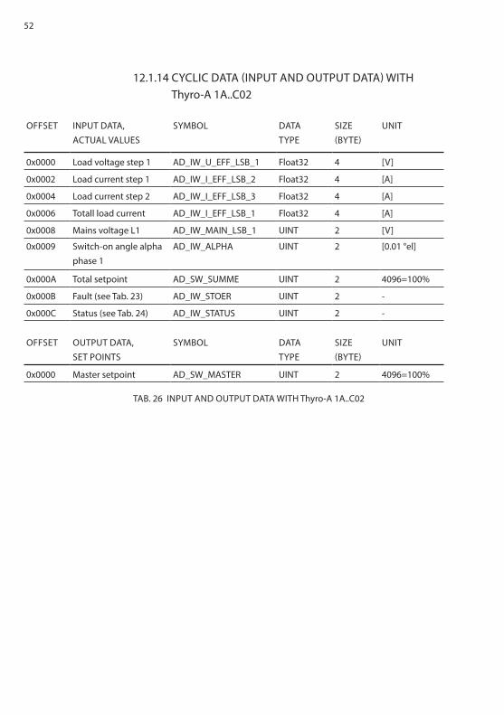
12.1.14 CYCLIC DATA (INPUT AND OUTPUT DATA) WITH Thyro-A 1A..C02
OFFSET INPUT DATA,ACTUAL VALUES
SYMBOL DATATYPE
SIZE (BYTE)
UNIT
0x0000 Load voltage step 1 AD_IW_U_EFF_LSB_1 Float32 4 [V]
0x0002 Load current step 1 AD_IW_I_EFF_LSB_2 Float32 4 [A]
0x0004 Load current step 2 AD_IW_I_EFF_LSB_3 Float32 4 [A]
0x0006 Totall load current AD_IW_I_EFF_LSB_1 Float32 4 [A]
0x0008 Mains voltage L1 AD_IW_MAIN_LSB_1 UINT 2 [V]
0x0009 Switch-on angle alpha phase 1
AD_IW_ALPHA UINT 2 [0.01 °el]
0x000A Total setpoint AD_SW_SUMME UINT 2 4096=100%
0x000B Fault (see Tab. 23) AD_IW_STOER UINT 2 -
0x000C Status (see Tab. 24) AD_IW_STATUS UINT 2 -
OFFSET OUTPUT DATA, SET POINTS
SYMBOL DATATYPE
SIZE (BYTE)
UNIT
0x0000 Master setpoint AD_SW_MASTER UINT 2 4096=100%
TAB. 26 INPUT AND OUTPUT DATA WITH Thyro-A 1A..C02

53
12.1.15 CYCLIC DATA (INPUT AND OUTPUT DATA) WITH Thyro-A 1A..C03
OFFSET INPUT DATA,ACTUAL VALUES
SYMBOL DATATYPE
SIZE (BYTE)
UNIT
0x0000 Load voltage L1 AD_IW_U_EFF_LSB_1 Float32 4 [V]
0x0002 Load current L1 AD_IW_I_EFF_LSB_1 Float32 4 [A]
0x0004 Power L1 AD_IW_P_LSB_1 Float32 4 [W]
0x0006 Mains voltage L1 AD_IW_MAIN_LSB_1 UINT 2 [V]
0x0007 Switch-on time TS AD_IW_TS UINT 2 [period]
0x0008 Switch-on angle alpha AD_IW_ALPHA UINT 2 [0.01 °el]
0x0009 Total setpoint AD_SW_SUMME UINT 2 4096=100%
0x000A Fault (see Tab. 23) AD_IW_STOER UINT 2 -
0x000B Status (see Tab. 24) AD_IW_STATUS UINT 2 -
OFFSET OUTPUT DATA, SET POINTS
SYMBOL DATATYPE
SIZE (BYTE)
UNIT
0x0000 Master setpoint AD_SW_MASTER UINT 2 4096=100%
TAB. 27 INPUT AND OUTPUT DATA WITH Thyro-A 1A..C03

54
12.1.16 CYCLIC DATA (INPUT AND OUTPUT DATA) WITH Thyro-A 1A..C05
OFFSET INPUT DATA,ACTUAL VALUES
SYMBOL DATATYPE
SIZE (BYTE)
UNIT
0x0000 Load voltage step 1 AD_IW_U_EFF_LSB_1 Float32 4 [V]
0x0002 Load current step 1 AD_IW_I_EFF_LSB_2 Float32 4 [A]
0x0004 Load current step 2 AD_IW_I_EFF_LSB_3 Float32 4 [A]
0x0006 Totall load current AD_IW_I_EFF_LSB_1 Float32 4 [A]
0x0008 Power step 1 AD_IW_P_LSB_1 Float32 4 [W]
0x000A Power step 2 AD_IW_P_LSB_3 Float32 4 [W]
0x000C Total power AD_IW_P_LSB_GES Float32 4 [W]
0x000E Mains voltage L1 AD_IW_MAIN_LSB_1 UINT 2 [V]
0x000F Switch-on angle alpha phase 1
AD_IW_ALPHA UINT 2 [0.01 °el]
0x0010 Total setpoint AD_SW_SUMME UINT 2 4096=100%
0x0011 Fehler (siehe Tab. 23) AD_IW_STOER UINT 2 -
0x0012 Status (siehe Tab. 24) AD_IW_STATUS UINT 2 -
OFFSET OUTPUT DATA, SET POINTS
SYMBOL DATATYPE
SIZE (BYTE)
UNIT
0x0000 Master setpoint AD_SW_MASTER UINT 2 4096=100%
TAB. 28 INPUT AND OUTPUT DATA WITH Thyro-A 1A..C05

55
12.1.17 CYCLIC DATA (INPUT AND OUTPUT DATA) WITH Thyro-A 1A..C07
12.2 CYCLIC DATA (INPUT AND OUTPUT DATA) WITH TPM, TSC AND TPM
The input and output data of Thyro-Power Manager, Thyro-Step Controller and Thyro-Measurement Unit depend on the operating mode. The following table shows the operating modes supported by the modules.
OFFSET INPUT DATA,ACTUAL VALUES
SYMBOL DATATYPE
SIZE (BYTE)
UNIT
0x0000 Load voltage L1 AD_IW_U_EFF_LSB_1 Float32 4 [V]
0x0002 Load current L1 AD_IW_I_EFF_LSB_1 Float32 4 [A]
0x0004 Power L1 AD_IW_P_LSB_1 Float32 4 [W]
0x0006 Mains voltage L1 AD_IW_MAIN_LSB_1 UINT 2 [V]
0x0007 Load temperature AD_P_IW_TEMP_LOAD UINT 2 [°C]
0x0008 Switch-on angle alpha AD_IW_ALPHA UINT 2 [0.01 °el]
0x0009 Total setpoint AD_SW_SUMME UINT 2 4096=100%
0x000A Fehler (siehe Tab. 23) AD_IW_STOER UINT 2 -
0x000B Status (siehe Tab. 24) AD_IW_STATUS UINT 2 -
OFFSET OUTPUT DATA, SET POINTS
SYMBOL DATATYPE
SIZE (BYTE)
UNIT
0x0000 Master setpoint AD_SW_MASTER UINT 2 4096=100%
TAB. 29 INPUT AND OUTPUT DATA WITH Thyro-A 1A..C07
TPM TSC TIO TMU
Automatic TPM_AUTO
Manual TPM_MAN
Thyro-Power Manager x x x x x
Thyro-Step Controller - - x x x
Thyro-Measurement Unit - - - x x
TAB. 30 SUPPORTED OPERATING MODES TPM, TSC, TIO, TMU

56
12.2.1 TPM AUTOMATIC AND MANUAL MODE (TPM_AUTO, TPM_MAN)
OFFSET INPUT DATA,ACTUAL VALUES
SYMBOL DATA TYPE
SIZE (BYTE)
UNIT
0x0000 AC input 1 AD_IW_I_EFF_LSB_1 Float32 4 [A],[V]
0x0002 AC input 2 AD_IW_I_EFF_LSB_2 Float32 4 [A],[V]
0x0004 AC input 3 AD_IW_I_EFF_LSB_3 Float32 4 [A],[V]
0x0006 Power AD_IW_P_LSB Float32 4 [W]
0x0008 Energy AD_IW_W_LSB_H Float32 4 [kWh]
0x000A DC input 1 AD_SW1_ANALOG UINT 2 4096=100%
0x000B DC input 2 AD_SW2_ANALOG UINT 2 4096=100%
0x000C DC input 3 AD_IW_RESERVE UINT 2 4096=100%
0x000D Mains voltage AD_IW_MAIN_LSB_1 UINT 2 [A]
0x000E Period duration AD_IW_FREQUENZ UINT 2 [µs]
0x000F Temperature AD_IW_TEMP_INT INT 2 [°C]
0x0010 Fault (see Tab. 35) AD_IW_ERROR1 UINT 2 -
0x0011 Status (see Tab. 36) AD_IW_STATUS1 UINT 2 -
TAB. 31 INPUT AND OUTPUT DATA WITH TPM_AUTO, TPM_MAN

57
12.2.2 TSC MODE
OFFSET INPUT DATA,ACTUAL VALUES
SYMBOL DATA TYPE
SIZE (BYTE)
UNIT
0x0000 AC input 1 AD_IW_I_EFF_LSB_1 Float32 4 [A],[V]
0x0002 AC input 2 AD_IW_I_EFF_LSB_2 Float32 4 [A],[V]
0x0004 AC input 3 AD_IW_I_EFF_LSB_3 Float32 4 [A],[V]
0x0006 Power AD_IW_P_LSB Float32 4 [W]
0x0008 Energy AD_IW_W_LSB_H Float32 4 [kWh]
0x000A DC input 1 AD_SW1_ANALOG UINT 2 4096=100%
0x000B DC input 2 AD_SW2_ANALOG UINT 2 4096=100%
0x000C DC input 3 AD_IW_RESERVE UINT 2 4096=100%
0x000D Mains voltage AD_IW_MAIN_LSB_1 UINT 2 [A]
0x000E Period duration AD_IW_FREQUENZ UINT 2 [µs]
0x000F Temperature AD_IW_TEMP_INT INT 2 [°C]
0x0010 Fault (see Tab. 35) AD_IW_ERROR1 UINT 2 -
0x0011 Status (see Tab. 36) AD_IW_STATUS1 UINT 2 -
0x0012 Analog output 4 AD_IW_DAC4 UINT 2 4096=100%
0x0013 Steps AD_IW_STEPS UINT 2 -
0x0014 Total setpoint AD_SW1_SUMME UINT 2 4096=100%
TAB. 32 INPUT AND OUTPUT DATA WITH TSC MODE

58
12.2.3 TIO MODE
OFFSET INPUT DATA,ACTUAL VALUES
SYMBOL DATA TYPE
SIZE (BYTE)
UNIT
0x0000 AC input 1 AD_IW_I_EFF_LSB_1 Float32 4 [A],[V]
0x0002 AC input 2 AD_IW_I_EFF_LSB_2 Float32 4 [A],[V]
0x0004 AC input 3 AD_IW_I_EFF_LSB_3 Float32 4 [A],[V]
0x0006 Power AD_IW_P_LSB Float32 4 [W]
0x0008 Energy AD_IW_W_LSB_H Float32 4 [kWh]
0x000A DC input 1 AD_SW1_ANALOG UINT 2 4096=100%
0x000B DC input 2 AD_SW2_ANALOG UINT 2 4096=100%
0x000C DC input 3 AD_IW_RESERVE UINT 2 4096=100%
0x000D Mains voltage AD_IW_MAIN_LSB_1 UINT 2 [A]
0x000E Period duration AD_IW_FREQUENZ UINT 2 [µs]
0x000F Temperature AD_IW_TEMP_INT INT 2 [°C]
0x0010 Fault (see Tab. 35) AD_IW_ERROR1 UINT 2 -
0x0011 Status (see Tab. 36) AD_IW_STATUS1 UINT 2 -
OFFSET OUTPUT DATA,SET POINTS
SYMBOL DATA TYPE
SIZE (BYTE)
UNIT
0x0000 Digital output AD_IW_COUNT UINT 2 4096=100%
0x0001 Analog output 1 AD_IW_DAC1 UINT 2 4096=100%
0x0002 Analog output 2 AD_IW_DAC2 UINT 2 4096=100%
0x0003 Analog output 3 AD_IW_DAC3 UINT 2 4096=100%
0x0004 Analog output 4 AD_IW_DAC4 UINT 2 4096=100%
0x0005 Analog output 5 AD_IW_DAC5 UINT 2 4096=100%
0x0006 Analog output 6 AD_IW_DAC6 UINT 2 4096=100%
TAB. 33 INPUT AND OUTPUT DATA WITH TIO MODE
59
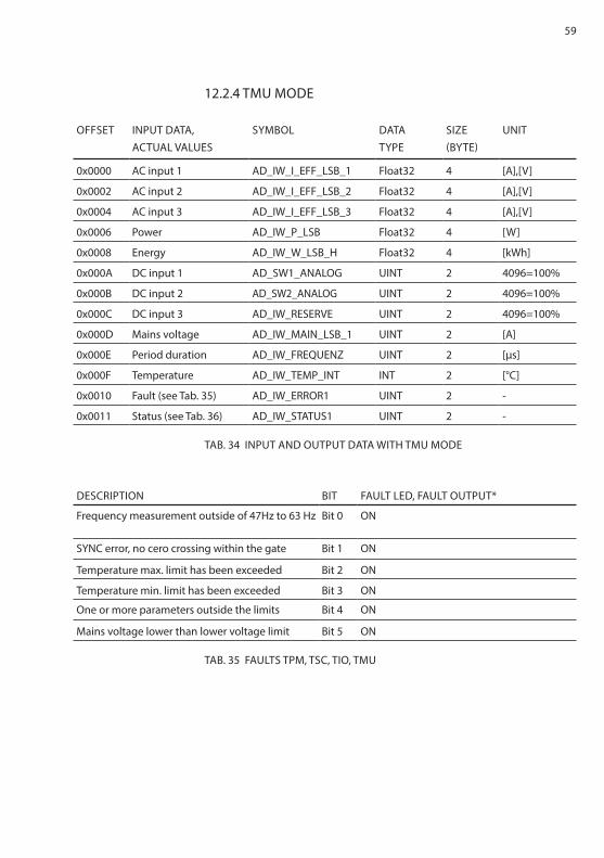
12.2.4 TMU MODE
OFFSET INPUT DATA,ACTUAL VALUES
SYMBOL DATA TYPE
SIZE (BYTE)
UNIT
0x0000 AC input 1 AD_IW_I_EFF_LSB_1 Float32 4 [A],[V]
0x0002 AC input 2 AD_IW_I_EFF_LSB_2 Float32 4 [A],[V]
0x0004 AC input 3 AD_IW_I_EFF_LSB_3 Float32 4 [A],[V]
0x0006 Power AD_IW_P_LSB Float32 4 [W]
0x0008 Energy AD_IW_W_LSB_H Float32 4 [kWh]
0x000A DC input 1 AD_SW1_ANALOG UINT 2 4096=100%
0x000B DC input 2 AD_SW2_ANALOG UINT 2 4096=100%
0x000C DC input 3 AD_IW_RESERVE UINT 2 4096=100%
0x000D Mains voltage AD_IW_MAIN_LSB_1 UINT 2 [A]
0x000E Period duration AD_IW_FREQUENZ UINT 2 [µs]
0x000F Temperature AD_IW_TEMP_INT INT 2 [°C]
0x0010 Fault (see Tab. 35) AD_IW_ERROR1 UINT 2 -
0x0011 Status (see Tab. 36) AD_IW_STATUS1 UINT 2 -
TAB. 34 INPUT AND OUTPUT DATA WITH TMU MODE
DESCRIPTION BIT FAULT LED, FAULT OUTPUT*
Frequency measurement outside of 47Hz to 63 Hz Bit 0 ON
SYNC error, no cero crossing within the gate Bit 1 ON
Temperature max. limit has been exceeded Bit 2 ON
Temperature min. limit has been exceeded Bit 3 ON
One or more parameters outside the limits Bit 4 ON
Mains voltage lower than lower voltage limit Bit 5 ON
TAB. 35 FAULTS TPM, TSC, TIO, TMU

60
DESCRIPTION BIT FAULT LED, FAULT OUTPUT*
Mains frequency is 60Hz Bit 2 OFF
Transformer 1 fallen below min. limit Bit 3 ON
Transformer 1 exceeded max. limit Bit 4 ON
Transformer 2 fallen below min. limit Bit 5 ON
Transformer 2 exceeded max. limit Bit 6 ON
Transformer 3 fallen below min. limit Bit 7 ON
Transformer 3 exceeded max. limit Bit 8 ON
Device switched off Bit 9 --
Wrong device Bit 10 --
Bus module active (0=no bus module/1=bus module active)
Bit 11 OFF
* Default setting can be parameterized.
TAB. 36 STATUS TPM, TSC, TIO, TMU
12.3 ACYCLIC PARAMETERS OF THE MODULESVia the acyclic parameter data transmission, parameters of the devices can be changed or selected. Acyclic parameters can be used for configuration and are usually read or written individually.The acyclic parameters are combined into two groups according to each module type:• Thyro-S, Thyro-A, Thyro-AX• TPM, TSP, TMU
12.3.1 ACYCLIC PARAMTERS FOR Thyro-S, Thyro-A and Thyro-AX
The table shows the parameters of the following product types:• Thyro-S 1S..H1, 1S..HRL1,• Thyro-A 1A..H1, 1A..HRL1, 1A..HRLP1, 2A..H1, 2A..HRL1, 2A..HRLP1 3A..H1, 3A..HRL1, 3A..HRLP1, 1A..C01, 1A..C02, 1A..C03, 1A..C05, 1A..C07• Thyro-AX 1A..HRL2, 1A..HRLP2 2A..HRL2, 2A..HRLP2 3A..HRL2, 3A..HRLP2

61
OFFSET SYMBOL NAME VALUE
RANGE
SIZE
(BYTE)
DATA
TYPE
R/W
0x0000 AD_P_I_TYP Controller type current 0… 2 UINT R
0x0001 AD_P_U_TYP Controller supply voltage 0…1000 2 UINT R
0x0002 AD_P_P_TYP_H Controller type output power 0… 4 UDINT R
0x0004 AD_P_BETR Operating mode 0…3 2 UINT R/W
0x0005 AD_P_AN1 Phase angle of 1st half wave 0…180 2 UINT R/W
0x0006 AD_P_SST Soft start duration (given) 2 UINT R/W
0x0007 AD_P_SDN Soft stop duration (given) 0…1000 2 UINT R/W
0x0008 AD_P_T0 Cycle period duration 0…1000 2 UINT R/W
0x0009 AD_P_MP Minimum interval 0...10 2 UINT R/W
0x000A AD_P_TSMA Maximum cycle turn on time 1...T0 2 UINT R/W
0x000B AD_P_TSMI Minimum cycle turn on time 0...T0 2 UINT R/W
0x000C AD_P_VIE Front pulse stop 0...180 2 UINT R/W
0x000D AD_P_HIE Back pulse stop 0...180 2 UINT R/W
0x000E AD_P_REGELUNG Control (analog output value) 0…8 2 UINT R/W
0x000F AD_P_TI PI controller, I part 0= aus 0…65535 2 UINT R/W
0x0010 AD_P_KP PI controller, P part 0= aus 0…65535 2 UINT R/W
0x0011 AD_P_KR PI controller, counter P part 0…65535 2 UINT R/W
0x0012 AD_P_TD Temperature coefficient of the
heating tape
0…65535 2 UINT R/W
0x0013 AD_P_UEMA Effective voltage setpoint
maximum
0… 2 UINT R/W
0x0014 AD_P_IEMA Effective current setpoint
maximum
0… 2 UINT R/W
0x0015 AD_P_PMA Power setpoint maximum 0… 4 UDINT R/W
0x0017 AD_SW_ENABLE Setpoint activation 0…3 2 UINT R
0x0018 AD_P_OF_A Actual value output offset 1 0...4096 2 UINT R/W
0x0019 AD_P_FA_A Scale end value actual value
output 1
0...4096 2 UINT R/W
0x001A AD_P_SPG_MIN Mains voltage monitoring min. 0…4096 2 UINT R/W
0x001B AD_P_SPG_MAX Mains voltage monitoring max. 0...1000 2 UINT R/W
0x001C AD_P_UN_S Undercurrent monitoring 0…1 (on, off) 2 UINT R/W
0x001D AD_P_RELAIS_CTRL2 Relay configuration 2 0…65535 bit
coded
2 UINT R/W
0x001E AD_P_LASTBRUCH_
MIN_ABS
Load fault, minimum value 0…4505 2 UINT R/W
0x001F AD_P_SYNC_ADR Synchro cycle address 0…65535 2 UINT R/W

62
OFFSET SYMBOL NAME VALUE
RANGE
SIZE
(BYTE)
DATA
TYPE
R/W
0x0020 AD_P_IMAB Pulse switch-off in case of failure 0…65535 bit
coded
2 UINT R/W
0x0021 AD_P_STA_RE Control start controller analog
setpoint
0…65535 2 UINT R/W
0x0022 AD_P_STE_RE Control end controller analog
setpoint
0…65535 2 UINT R/W
0x0023 AD_P_STATUS_3A Configuration 3A 2 UINT R/W
0x0024 AD_P_MOSI_FA Peak current value limit 0…4096 2 UINT R/W
0x0025 AD_P_DAC1_CTRL Analog output configuration 1 0…10 2 UINT R/W
0x0026 AD_P_VER_DAY Version day 1…31 2 UINT R
0x0027 AD_P_VER_MONTH Version month 1…12 2 UINT R
0x0028 AD_P_VER_JEAR Version year 0…9999 2 UINT R
0x0029 AD_P_REGLERSP_ANF Controller inhibit 0…1 (on, off) 2 UINT R/W
0x002A AD_P_RELAIS_CTRL Relay configuration 1 0…65535 bit
coded
2 UINT R/W
0x002B AD_P_DAC_MITTEL-
WERT
Averaging analog output 1 0…65535 2 UINT R/W
0x002C AD_P_FA_NR_
GERAET_H
Device number 4 UDINT R
0x002E AD_P_FA_LFD_NR Serial number 2 UINT R
0x002F AD_P_FA_NR_LK_H PCB number 4 UDINT R
0x0031 AD_P_DAC_MITTEL-
WERT_2
Averaging analog output 2 0…65535 2 UINT R/W
0x0032 AD_P_OF_A_2 Actual value output offset 2 0…4096 2 UINT R/W
0x0033 AD_P_FA_A_2 Scale end value actual value
output 2
0…4096 2 UINT R/W
0x0034 AD_P_DAC2_CTRL Analog output configuration 2 0…10 2 UINT R/W
0x0035 AD_P_DAC_MITTEL-
WERT_3
Averaging analog output 3 0…65535 2 UINT R/W
0x0036 AD_P_OF_A_3 Actual value output offset 3 0…4096 2 UINT R/W
0x0037 AD_P_FA_A_3 Scale end value actual value
output 3
0…4096 2 UINT R/W
0x0038 AD_P_DAC3_CTRL Analog output configuration 3 0…10 2 UINT R/W
0x0039 AD_P_U_MIN Voltage limit minimum 0…65535 2 UINT R/W
0x003A AD_P_U_MAX Voltage limit maximum 0…65535 2 UINT R/W
0x003B AD_P_I_MIN Current limit minimum 0…65535 2 UINT R/W
0x003C AD_P_I_MAX Current limit maximum 0…65535 2 UINT R/W
0x003D AD_P_P_MIN Power limit minimum 0… 4 UDINT R/W
0x003F AD_P_P_MAX Power limit maximum 0… 4 UDINT R/W
TAB. 37 ACYCLIC PARAMETERS OF Thyro-S, Thyro-A and Thyro-AX

63
12.3.2 ACYCLIC PARAMETERS OF TPM, TSC AND TMUThe acyclic parameters for the modules TPM, TSC and TMU are listed in table below:
OFFSET SYMBOL NAME VALUE
RANGE
SIZE
(BYTE)
DATA
TYPE
R/W
0x0000 AD_P_W1_TYP Type value transformer 1 1..65535 2 UINT R/W
0x0001 AD_P_W2_TYP Type value transformer 2 1..65535 2 UINT R/W
0x0002 AD_P_W3_TYP Type value transformer 3 1..65535 2 UINT R/W
0x0003 AD_P_WANDLER_CTRL Transformer setting 0..65535 bit
coded
2 UINT R/W
0x0004 AD_P_U_TYP Type value U mains 1..260 2 UINT R/W
0x0005 AD_P_T0 Measuring and cycle time 1…1500 2 UINT R/W
0x0006 AD_P_SYT_ANZ Number 1..11 2 UINT R/W
0x0007 AD_P_SYT_T01 1st phase 0..T0 2 UINT R/W
0x0008 AD_P_SYT_T02 2nd phase 0..T0 2 UINT R/W
0x0009 AD_P_SYT_T03 3rd phase 0..T0 2 UINT R/W
0x000A AD_P_SYT_T04 4th phase 0..T0 2 UINT R/W
0x000B AD_P_SYT_T05 5th phase 0..T0 2 UINT R/W
0x000C AD_P_SYT_T06 6th phase 0..T0 2 UINT R/W
0x000D AD_P_SYT_T07 7th phase 0..T0 2 UINT R/W
0x000E AD_P_SYT_T08 8th phase 0..T0 2 UINT R/W
0x000F AD_P_SYT_T09 9th phase 0..T0 2 UINT R/W
0x0010 AD_P_SYT_T10 10th phase 0..T0 2 UINT R/W
0x0011 AD_SW1_STA Control start setpoint 1 0…4096 2 UINT R/W
0x0012 AD_SW1_STE Control stop setpoint 1 0…4096 2 UINT R/W
0x0013 AD_SW2_STA Control start setpoint 2 0…4096 2 UINT R/W
0x0014 AD_SW2_STE Control stop setpoint 2 0…4096 2 UINT R/W
0x0015 AD_P_DAC1_OF Offset 1 0..4095 2 UINT R/W
0x0016 AD_P_DAC1_FA Scale end value 1 0..4096 2 UINT R/W
0x0017 AD_P_DAC1_CTRL Output value 1 1..16 2 UINT R/W
0x0018 AD_P_DAC2_OF Offset 2 0..4095 2 UINT R/W
0x0019 AD_P_DAC2_FA Scale end value 2 0..4096 2 UINT R/W
0x001A AD_P_DAC2_CTRL Output value 2 1..16 2 UINT R/W
0x001B AD_P_DAC3_OF Offset 3 0..4095 2 UINT R/W
0x001C AD_P_DAC3_FA Scale end value 3 0..4096 2 UINT R/W
0x001D AD_P_DAC3_CTRL Output value 3 1..16 2 UINT R/W
0x001E AD_P_DAC4_OF Offset 4 0..4095 2 UINT R/W
0x001F AD_P_DAC4_FA Scale end value 4 0..4096 2 UINT R/W
0x0020 AD_P_DAC4_CTRL Output value 4 1..16 2 UINT R/W

64
OFFSET SYMBOL NAME VALUE
RANGE
SIZE
(BYTE)
DATA
TYPE
R/W
0x0021 AD_P_DAC5_OF Offset 5 0..4095 2 UINT R/W
0x0022 AD_P_DAC5_FA Scale end value 5 0..4096 2 UINT R/W
0x0023 AD_P_DAC5_CTRL Output value 5 1..16 2 UINT R/W
0x0024 AD_P_DAC6_OF Offset 6 0..4095 2 UINT R/W
0x0025 AD_P_DAC6_FA Scale end value 6 0..4096 2 UINT R/W
0x0026 AD_P_DAC6_CTRL Output value 6 1..16 2 UINT R/W
0x0027 AD_P_DAC_
MITTELWERT
Average 0…65355 2 UINT R/W
0x0028 AD_P_SPG_MIN Lower limit mains voltage 0…5120 2 UINT R/W
0x0029 AD_P_SPG_MAX Upper limit mains voltage 0…5120 2 UINT R/W
0x002A AD_P_W1_MAX Limit transformer 1 0…8192 2 UINT R/W
0x002B AD_P_W2_MAX Limit transformer 2 0…8192 2 UINT R/W
0x002C AD_P_W3_MAX Limit transformer 3 0…8192 2 UINT R/W
0x002D AD_P_WATCH_CTRL Monitoring mode transformer 0…65535 bit
coded
2 UINT R/W
0x002E AD_P_ERROR_CTRL1 Fault output 0…65535 bit
coded
2 UINT R/W
0x002F AD_P_ALARM_CTRL1 Alarm output 0…65535 bit
coded
2 UINT R/W
0x0030 AD_P_VER_DAY Firmware version day 1…31 2 UINT R
0x0031 AD_P_VER_MONTH Firmware version month 1…12 2 UINT R
0x0032 AD_P_VER_YEAR Firmware version year 0…9999 2 UINT R
0x0033 AD_P_TEMP_MAX Limiting value temperature 0…255 2 UINT R/W
0x0034 AD_P_FA_NR_
GERAET_H
Device number 0… 4 UDINT R
0x0036 AD_P_FA_LFD_NR Serial number 0… 2 UINT R
0x0037 AD_P_FA_NR_LK_H PCB number 0… 4 UDINT R
0x0039 AD_P_FREQUENZ_MIN_
MAX
Frequency limit 100…2500 2 UINT R
0x003A AD_P_FREQUENZ_TOL Frequency tolerance 1…25 2 UINT R
0x003B AD_P_DAC4_CTRL_TSC 2 UINT R
TAB. 38 ACYCLIC PARAMETERS OF TPM, TSC AND TMU

65
13. EXTERNAL CONNECTIONS
13.1 POWER SUPPLY+24 V to X11, current consumption approx. 150 mA
The foregoing circuit diagram shows the connection of the bus module.
Abb. in deutsch??
supply
24V DC (approx. 150mA)
bridge (contact)Thyro-S: see chapter 6.1Thyro-A/Thyro-AX: see chapter 6.2
X1 - X8 to the power controllers
Screen connections
Thyro-AX...H RLP2
Thyro-A...H1...H RL1...H RLP1
Thyro-S...H1...H RL1
TPMTSCTMU

66
13.2 OPERATING ELEMENTS AND TERMINAL BLOCKSThis chapter describes the available terminal blocks, plug connectors and operating elements.
Configuration of the 7 pin connector of slots X1 to X8:1. Switched ground potential. All pins 1 of slots X1 to X8 are connected.2. RxD3. TxD4. Ground5. Switchable ground potential. The slots X1 to X8 can be switched as desired.6. Ground7. Ground potential for shield connection
Configuration of the 3 pin connector X11:X11.1 +24 VX11.2 24 V – groundX11.3 Grounding, cable should be as short as possible for EMC reasons

67
14. INTERFACES
14.1 SYSTEM INTERFACESThe bus module is connected with the relevant system interfaces of the power controllers via X1 to X8 (four-wire, 2x2 twisted, shared shielding). The transmission rate is 38,400 Bd. The asynchronous characters are transferred with 8bit, no parity, and one stop bit. The protocol starts with STX, followed by an identifier, the data, and is concluded with a check sum. Invalid frames are ignored.
14.2 ETHERNET INTERFACECommunication medium CAT 5eNetwork topology tree, star and lineMaximum cable length 100 mModbus participants restricted to the maximum supported num-
ber of devices by the controller usedTransmission rate 100 MBit/s

68
FIG. 2 CONNECTION DIAGRAM Thyro-A/Thyro-AX
15. CONNECTION DIAGRAMS Thyro-A/Thyro-AX

69
FIG. 3 CONNECTION DIAGRAM Thyro-S
16. CONNECTION DIAGRAMS Thyro-S
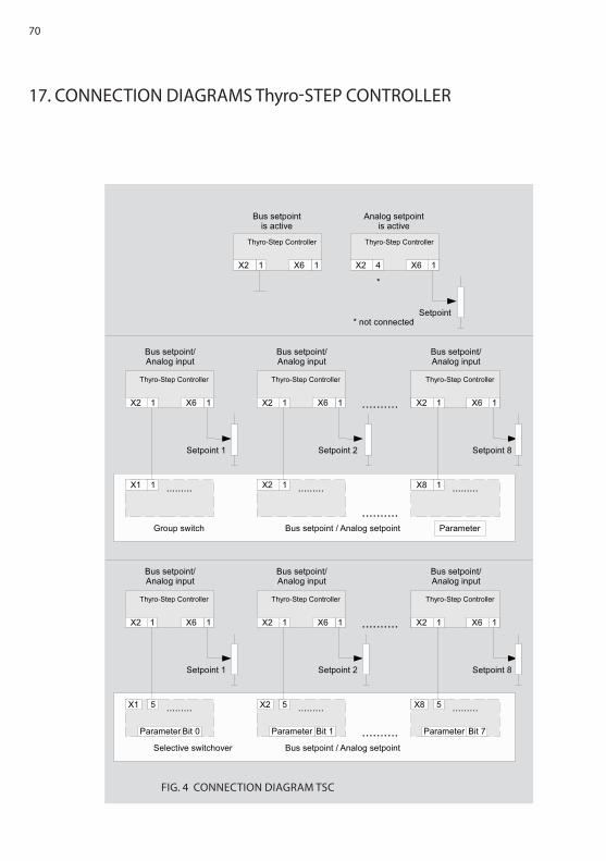
70
FIG. 4 CONNECTION DIAGRAM TSC
17. CONNECTION DIAGRAMS Thyro-STEP CONTROLLER

71
18. CHECKLIST
19. TECHNICAL DATA
• Address switch has to be set according to the bus module plan,• process with wiring,• connect 24 V DC – green LED is flashing, bus module is ready to use,• flashing red LED goes out when the bus starts its operations
Power supply: 24 VDC (+/-20 %)150 mAConnection options: for up to 8 Advanced Energy power controllers
of series Thyro-S, Thyro-A, Thyro-AX and the Thyro-Power Manger, Thyro-Step Controller and Thyro-Measurement Unit series
Function control: LEDAssembly: DIN railAmbient temperature: maximum 55 °CDimensions (WxDxH): 150 x 60 x 95mmWeight circa: 0.35 kg

72
20. DIMENSION DRAWINGS
55 mm height
incl. cover

73
21. ADDITIONAL OPTIONS
22. APPROVALS AND CONFORMITY
Ready-made bus module-side shielded cables are available.A set of cables consist of 4 connection cables for connecting 4 power control-lers.
Best.-Nr. 2000 000 848 Bus module connection cable for 4 controllers, 2.5 m long
Best.-Nr. 2000 000 849 Bus module connection cable for 4 controllers, 1.5 m long
• Quality standard in acc. to DIN EN ISO 9001• CE conformity• Low voltage directives 2006/95/EG• EMV directives 2004/108/EG• RoHS compliant 5/6
The devices of the type range indicated on the cover page, Modbus bus module is a part of these, conform to the currently applicable EN 50178 and EN 60146-1-1.The CE mark on the device confirms observation of the general EG guidelines for 2006/95/EG - low voltage and for 2004/108/EG – electromagnet compati-bility, if the instructions on installation and commissioning described in the operating instructions are observed.Regulations and definitions for qualified personnel are contained in DIN 57105/VDE 0105 Part 1.Safe isolation according to VDE 0160 (EN 50178 Chapter 3).

74
DEVICE APPLICATION CONDITIONS
Modbus Application Protocol Specification Version 1.1b 2006
Built-in device (VDE0160) DIN EN 50 178
Storage temperature (D) -25 °C - +55 °C
Transport temperature (E) -25 °C - +70 °C
Operating temperature (better B) -10 °C - +55 °C
Humidity class B DIN EN 50 178 tab. 7 (EN 60 721)
Degree of contamination 2 DIN EN 50 178 Tab. 2
Air pressure 900 mbar * 1000 m über NNl
Degree of protection IP00 DIN EN 69 529
EMC-testing DIN EN 61000-6-2 (-4)
Emitted interference CISPR 16
Radiated immunity EN/IEC 61000-4-3
Conducted immunity EN/IEC 61000-4-6
ESD 8kV (A) EN/IEC 61000-4-2
Burst control lines 1kV (A) EN 61000-4-4
IN DETAIL

75
World Headquarters
1625 Sharp Point Drive
Fort Collins, CO 80525 USA
970.221.4670 Main
970.221.5583 Fax
www.advanced-energy.com
Specifications are subject to change without notice.
© 2014 Advanced Energy Industries, Inc. All rights reserved. Advanced Energy® and Thyro-S™, Thyro-A™, Thyro-AX™ are trademarks of Advanced Energy Industries, Inc.

76