fmbt-21 modbus/tcp adapter module user’s manual modbus/tcp adapter module user’s manual...
TRANSCRIPT

Options for ABB drives, converters and inverters
User’s manualFMBT-21 Modbus/TCP adapter module

List of related manuals
The links above contain lists of documents. You can find manuals and other product documents in PDF format on the Internet. See section Document library on the Internet on the inside of the back cover. For manuals not available in the Document library, contact your local ABB representative.
Drive manuals and guides Code (link lists)(EN/Multilingual)
ACS380-04 manuals 9AAK10103A6193ACS480 manuals 9AKK106930A8739 ACS580-01 manuals 9AKK105713A8085ACH580-01 manuals 9AKK10103A0587ACQ580-01 manuals 9AKK106713A2709ACS580-04 manuals 9AKK106930A9060ACH580-04 manuals 9AKK106930A9059ACQ580-04 manuals 9AKK106930A9053ACS580-07 manuals 9AKK106930A5239ACH580-07 manuals 9AKK106930A5241ACQ580-07 manuals 9AKK106930A3150ACS880-01 manuals 9AKK105408A7004ACS880-04 manuals 9AKK105713A4819ACS880-07 (45 to 710 kW) manuals 9AKK105408A8149ACS880-17 (132 to 355 kW) manuals 9AKK106930A3466ACS880-37 (132 to 355 kW) manuals 9AKK106930A3467
Option manuals and guidesFMBT-21 Modbus/TCP adapter module user’s manual 3AXD50000158607
Fieldbus connectivity web pageFMBT-21 manual

User’s manual
FMBT-21 Modbus/TCP adapter module
3AXD50000158607 Rev AENEFFECTIVE: 2017-11-30
2017 ABB OyAll Rights Reserved.
7. Modbus/TCP – Start-up
1. Safety instructions
Table of contents
4. Mechanical installation
5. Electrical installation

4

Table of contents 5
Table of contents
List of related manuals . . . . . . . . . . . . . . . . . . . . . . . . . . . . . . . . . 2
1. Safety instructionsContents of this chapter . . . . . . . . . . . . . . . . . . . . . . . . . . . . . . . . 9Use of warnings . . . . . . . . . . . . . . . . . . . . . . . . . . . . . . . . . . . . . 10Safety in installation . . . . . . . . . . . . . . . . . . . . . . . . . . . . . . . . . . 11
2. Introduction to the manualContents of this chapter . . . . . . . . . . . . . . . . . . . . . . . . . . . . . . . 13Purpose of the manual . . . . . . . . . . . . . . . . . . . . . . . . . . . . . . . . 13Applicability . . . . . . . . . . . . . . . . . . . . . . . . . . . . . . . . . . . . . . . . 13Compatibility . . . . . . . . . . . . . . . . . . . . . . . . . . . . . . . . . . . . . . . 13
Drives . . . . . . . . . . . . . . . . . . . . . . . . . . . . . . . . . . . . . . . . . 14Protocols . . . . . . . . . . . . . . . . . . . . . . . . . . . . . . . . . . . . . . . 14Tools . . . . . . . . . . . . . . . . . . . . . . . . . . . . . . . . . . . . . . . . . . 15
Target audience . . . . . . . . . . . . . . . . . . . . . . . . . . . . . . . . . . . . . 15Contents . . . . . . . . . . . . . . . . . . . . . . . . . . . . . . . . . . . . . . . . . . . 16
Cybersecurity disclaimer . . . . . . . . . . . . . . . . . . . . . . . . . . . 17Terms and abbreviations . . . . . . . . . . . . . . . . . . . . . . . . . . . . . . 18
General terms . . . . . . . . . . . . . . . . . . . . . . . . . . . . . . . . . . . 18Abbreviations . . . . . . . . . . . . . . . . . . . . . . . . . . . . . . . . . . . . 18Modbus/TCP terms and abbreviations . . . . . . . . . . . . . . . . 19
3. Overview of the Ethernet network and the FMBT-21 moduleContents of this chapter . . . . . . . . . . . . . . . . . . . . . . . . . . . . . . . 21Ethernet network . . . . . . . . . . . . . . . . . . . . . . . . . . . . . . . . . . . . 21
Example topology of the Ethernet link . . . . . . . . . . . . . . . . . 22FMBT-21 Modbus/TCP adapter module . . . . . . . . . . . . . . . . . . 23
Layout of the adapter module . . . . . . . . . . . . . . . . . . . . . . . 24
4. Mechanical installationContents of this chapter . . . . . . . . . . . . . . . . . . . . . . . . . . . . . . . 25

6 Table of contents
Necessary tools and instructions . . . . . . . . . . . . . . . . . . . . . . . . 25Unpacking and examining the delivery . . . . . . . . . . . . . . . . . . . . 25Installing the adapter module . . . . . . . . . . . . . . . . . . . . . . . . . . . 26
5. Electrical installationContents of this chapter . . . . . . . . . . . . . . . . . . . . . . . . . . . . . . . 29Warnings . . . . . . . . . . . . . . . . . . . . . . . . . . . . . . . . . . . . . . . . . . 29Necessary tools and instructions . . . . . . . . . . . . . . . . . . . . . . . . 29General cabling instructions . . . . . . . . . . . . . . . . . . . . . . . . . . . . 30Connecting the adapter module to the Ethernet network . . . . . . 30
Connection procedure . . . . . . . . . . . . . . . . . . . . . . . . . . . . . 30
Modbus/TCP protocol
6. Modbus/TCP – Start-upContents of this chapter . . . . . . . . . . . . . . . . . . . . . . . . . . . . . . . 33Warnings . . . . . . . . . . . . . . . . . . . . . . . . . . . . . . . . . . . . . . . . . . 33Drive configuration . . . . . . . . . . . . . . . . . . . . . . . . . . . . . . . . . . . 34
Modbus/TCP connection configuration . . . . . . . . . . . . . . . . 34FMBT-21 configuration parameters – group A (group 1) 35FMBT-21configuration parameters – group B (group 2). 44FMBT-21 configuration parameters – group C (group 3) 45
Control locations . . . . . . . . . . . . . . . . . . . . . . . . . . . . . . . . . 46Starting up fieldbus communication for ACS480, ACx580 and ACS880 drives . . . . . . . . . . . . . . . . . . . . . . . . . . . . . . . . . . . . . . 46
Parameter setting examples – ACS480 and ACx580 drives 48Frequency control using the ABB Drives – Enhanced communication profile. . . . . . . . . . . . . . . . . . . . . . . . . . . 48
Parameter setting examples – ACS880 . . . . . . . . . . . . . . . . 51Speed control using the ABB Drives – Enhanced communication profile. . . . . . . . . . . . . . . . . . . . . . . . . . . 51
Client configuration . . . . . . . . . . . . . . . . . . . . . . . . . . . . . . . . . . 54Modbus register maps . . . . . . . . . . . . . . . . . . . . . . . . . . . . . 54
7. Modbus/TCP – Communication profilesContents of this chapter . . . . . . . . . . . . . . . . . . . . . . . . . . . . . . . 55Communication profiles . . . . . . . . . . . . . . . . . . . . . . . . . . . . . . . 55
Table of contents 7
ABB Drives communication profile . . . . . . . . . . . . . . . . . . . . . . . 57Control word and Status word . . . . . . . . . . . . . . . . . . . . . . . 57
Control word contents . . . . . . . . . . . . . . . . . . . . . . . . . . 57Status word contents . . . . . . . . . . . . . . . . . . . . . . . . . . . 59State machine . . . . . . . . . . . . . . . . . . . . . . . . . . . . . . . . 61
References . . . . . . . . . . . . . . . . . . . . . . . . . . . . . . . . . . . . . 62Scaling . . . . . . . . . . . . . . . . . . . . . . . . . . . . . . . . . . . . . . 62
Actual values . . . . . . . . . . . . . . . . . . . . . . . . . . . . . . . . . . . . 63Scaling . . . . . . . . . . . . . . . . . . . . . . . . . . . . . . . . . . . . . . 63
8. Modbus/TCP – Communication protocolContents of this chapter . . . . . . . . . . . . . . . . . . . . . . . . . . . . . . . 65Modbus/TCP . . . . . . . . . . . . . . . . . . . . . . . . . . . . . . . . . . . . . . . 65Register addressing . . . . . . . . . . . . . . . . . . . . . . . . . . . . . . . . . . 66Function codes . . . . . . . . . . . . . . . . . . . . . . . . . . . . . . . . . . . . . . 66Encapsulated Interface Transport / Read Device Identification . 67Exception codes . . . . . . . . . . . . . . . . . . . . . . . . . . . . . . . . . . . . . 68Communication profiles . . . . . . . . . . . . . . . . . . . . . . . . . . . . . . . 68
ABB Drives profile - Classic . . . . . . . . . . . . . . . . . . . . . . . . . 69ABB Drives profile - Enhanced . . . . . . . . . . . . . . . . . . . . . . 70Transparent 16-bit . . . . . . . . . . . . . . . . . . . . . . . . . . . . . . . . 72Transparent 32-bit . . . . . . . . . . . . . . . . . . . . . . . . . . . . . . . . 74
9. Modbus/TCP – DiagnosticsContents of this chapter . . . . . . . . . . . . . . . . . . . . . . . . . . . . . . . 77Fault and warning messages . . . . . . . . . . . . . . . . . . . . . . . . . . . 77LEDs . . . . . . . . . . . . . . . . . . . . . . . . . . . . . . . . . . . . . . . . . . . . . 78Internal error code registers . . . . . . . . . . . . . . . . . . . . . . . . . . . . 80
NONE protocol selection
10. NONE – Start-upContents of this chapter . . . . . . . . . . . . . . . . . . . . . . . . . . . . . . . 85Warnings . . . . . . . . . . . . . . . . . . . . . . . . . . . . . . . . . . . . . . . . . . 85Drive configuration . . . . . . . . . . . . . . . . . . . . . . . . . . . . . . . . . . . 86
Connection configuration using NONE protocol . . . . . . . . . 86FMBT-21 configuration parameters – group A (group 1) 87

8 Table of contents
Starting up fieldbus communication . . . . . . . . . . . . . . . . . . . . . . 93
11. NONE – DiagnosticsContents of this chapter . . . . . . . . . . . . . . . . . . . . . . . . . . . . . . . 95Fault and warning messages . . . . . . . . . . . . . . . . . . . . . . . . . . . 95LEDs . . . . . . . . . . . . . . . . . . . . . . . . . . . . . . . . . . . . . . . . . . . . . 96
12. Technical dataContents of this chapter . . . . . . . . . . . . . . . . . . . . . . . . . . . . . . . 99FMBT-21 . . . . . . . . . . . . . . . . . . . . . . . . . . . . . . . . . . . . . . . . . 100Ethernet link . . . . . . . . . . . . . . . . . . . . . . . . . . . . . . . . . . . . . . . 101TCP and UDP service ports . . . . . . . . . . . . . . . . . . . . . . . . . . . 102
13. Appendix A – ABB IP configuration tool for FMBT-21Contents of this chapter . . . . . . . . . . . . . . . . . . . . . . . . . . . . . . 103Installation . . . . . . . . . . . . . . . . . . . . . . . . . . . . . . . . . . . . . . . . 103Finding adapter modules in the network . . . . . . . . . . . . . . . . . 104Rewriting the IP configuration of adapter modules . . . . . . . . . . 105
Further informationProduct and service inquiries . . . . . . . . . . . . . . . . . . . . . . . . . . 107Product training . . . . . . . . . . . . . . . . . . . . . . . . . . . . . . . . . . . . 107Providing feedback on ABB Drives manuals . . . . . . . . . . . . . . 107Document library on the Internet . . . . . . . . . . . . . . . . . . . . . . . 107

Safety instructions 9
1Safety instructions
Contents of this chapter
The chapter contains the warning symbols used in this manual and the safety instructions which you must obey when you install or connect an optional module to a drive, converter or inverter. If you ignore the safety instructions, injury, death or damage can occur. Read this chapter before you start the installation.

10 Safety instructions
Use of warnings
Warnings tell you about conditions which can cause injury or death, or damage to the equipment. They also tell you how to prevent the danger. The manual uses these warning symbols:
Electricity warning tells you about hazards from electricity which can cause injury or death, or damage to the equipment.
General warning tells you about conditions, other than those caused by electricity, which can cause injury or death, or damage to the equipment.

Safety instructions 11
Safety in installation
These instructions are for all who install or connect an optional module to a drive, converter or inverter and need to open its front cover or door to do the work.
WARNING! Obey these instructions. If you ignore them, injury or death, or damage to the equipment can occur.
• If you are not a qualified electrician, do not do installation or maintenance work.
• Disconnect the drive, converter or inverter from all possible power sources. After you have disconnected the drive, converter or inverter, always wait for 5 minutes to let the intermediate circuit capacitors discharge before you continue.
• Disconnect all dangerous voltages connected to other control signal connectors in reach. For example, it is possible that 230 V AC is connected from outside to a relay output of the drive, converter or inverter.
• Always use a multimeter to make sure that there are no parts under voltage in reach. The impedance of the multimeter must be at least 1 Mohm.

12 Safety instructions

Introduction to the manual 13
2Introduction to the manual
Contents of this chapter
This chapter introduces this manual.
Purpose of the manual
The manual provides information on installing, commissioning and using the FMBT-21 Modbus/TCP adapter module.
Applicability
This manual applies to the FMBT-21 Modbus/TCP Ethernet adapter module, software version 1.00 and later.
Compatibility
The FMBT-21 Modbus/TCP adapter module is compatible with different ABB drives, solar inverters and wind turbine converters.
Note: Later in this manual, the term drive is used to refer converters and inverters as well.

14 Introduction to the manual
Drives
The table below shows the compatibility of the FMBT-21 adapter module with different ABB drives.
Note: Not all compatible drives are listed here. For details of compatibility, check the drive’s firmware manual.
Protocols
The FMBT-21 adapter module is compatible with Ethernet standards IEEE 802.3 and IEEE 802.3u.
The FMBT-21 adapter module supports these protocols from SW version 1.00 onwards:
• Modbus/TCP
• Modbus over UDP
In addition to these protocol, it is possible to have the no communication protocol running on the FMBT-21 adapter module. This configuration is called NONE protocol. In this setup, the FMBT-21 adapter module is used only for running Ethernet services which can be enabled/disabled via parameter 51.15 Service configuration.
Drives FMBT-21
ACS380 x
ACS480 x
ACS580 series x
ACH580 series x
ACQ580 series x
ACS880 series x
Introduction to the manual 15
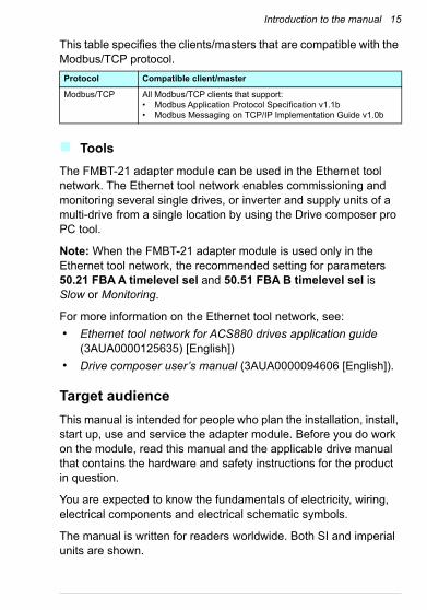
This table specifies the clients/masters that are compatible with the Modbus/TCP protocol.
Tools
The FMBT-21 adapter module can be used in the Ethernet tool network. The Ethernet tool network enables commissioning and monitoring several single drives, or inverter and supply units of a multi-drive from a single location by using the Drive composer pro PC tool.
Note: When the FMBT-21 adapter module is used only in the Ethernet tool network, the recommended setting for parameters 50.21 FBA A timelevel sel and 50.51 FBA B timelevel sel is Slow or Monitoring.
For more information on the Ethernet tool network, see:
• Ethernet tool network for ACS880 drives application guide (3AUA0000125635) [English])
• Drive composer user’s manual (3AUA0000094606 [English]).
Target audience
This manual is intended for people who plan the installation, install, start up, use and service the adapter module. Before you do work on the module, read this manual and the applicable drive manual that contains the hardware and safety instructions for the product in question.
You are expected to know the fundamentals of electricity, wiring, electrical components and electrical schematic symbols.
The manual is written for readers worldwide. Both SI and imperial units are shown.
Protocol Compatible client/master
Modbus/TCP All Modbus/TCP clients that support:• Modbus Application Protocol Specification v1.1b• Modbus Messaging on TCP/IP Implementation Guide v1.0b

16 Introduction to the manual
Contents
The manual consists of the following chapters:
• Safety instructions gives the safety instructions which you must obey when you install a fieldbus adapter module.
• Overview of the Ethernet network and the FMBT-21 module contains a short description of the Ethernet network and the adapter module.
• Mechanical installation contains a delivery checklist and instructions on installing the adapter module.
• Electrical installation contains instructions on cabling and connecting the adapter module to the Ethernet network.
• Technical data contains the technical data of the adapter module and the Ethernet link.
• Appendix A – ABB IP configuration tool for FMBT-21 shows how to use the APP IP configuration tool for the FMBT-21.
Modbus/TCP protocol
• Modbus/TCP – Start-up presents the steps to take during the start-up of the drive with the adapter module and gives information on configuring the Modbus/TCP client.
• Modbus/TCP – Communication profiles describes the communication profiles used in the communication between the client, the adapter module and the drive.
• Modbus/TCP – Communication protocol describes the Modbus/TCP communication protocol for the adapter module.
• Modbus/TCP – Diagnostics explains how to trace faults with the status LEDs on the adapter module.
NONE protocol selection
• NONE – Start-up presents the steps to take during the start-up of the drive with the adapter module and gives examples of configuring the NONE protocol.
• NONE – Diagnostics explains how to trace faults with the status LEDs on the adapter module.

Introduction to the manual 17
Cybersecurity disclaimer
This product is designed to be connected to and to communicate information and data via a network interface. It is Customer's sole responsibility to provide and continuously ensure a secure connection between the product and Customer network or any other network (as the case may be). Customer shall establish and maintain any appropriate measures (such as but not limited to the installation of firewalls, application of authentication measures, encryption of data, installation of anti-virus programs, etc.) to protect the product, the network, its system and the interface against any kind of security breaches, unauthorized access, interference, intrusion, leakage and/or theft of data or information. ABB and its affiliates are not liable for damages and/or losses related to such security breaches, any unauthorized access, interference, intrusion, leakage and/or theft of data or information.

18 Introduction to the manual
Terms and abbreviations
General terms
Abbreviations
Term Definition
ACx580 ACS580, ACH580 or ACQ580
Command word See Control word.
Control word 16-bit or 32-bit word from master to slave with bit-coded control signals (sometimes called the Command word).
Drive Frequency converter for controlling AC motors. The drive consists of a rectifier and an inverter connected together by the DC link. In drives up to approximately 500 kW, these are integrated into a single module (drive module). Larger drives typically consist of separate supply and inverter units.This manual uses the term drive to refer converters and inverter as well.
FMBT-21 adapter module
One of the optional fieldbus adapter modules available for ABB drives. FMBT-21 is a device through which an ABB drive is connected to an Ethernet network.
Fieldbus adapter module
Device through which the drive is connected to an external communication network, that is, a fieldbus. The communication with the module is activated with a drive parameter.
MAC address Media Access Control address.A unique factory-programmed identifier used to address a node in an Ethernet network.
Profile Adaptation of the protocol for certain application field, for example, drives.In this manual, drive-internal profiles (eg, DCU or FBA) are called native profiles.
Status word 16-bit or 32-bit word from slave to master with bit-coded status messages.
Abbreviation Explanation
DHCP Dynamic Host Control Protocol. A protocol for automating the configuration of IP devices. DHCP can be used to automatically assign IP addresses and related network information.
EMC Electromagnetic compatibility
FBA Fieldbus adapter
LSB Least significant bit
Introduction to the manual 19
Modbus/TCP terms and abbreviations
MSB Most significant bit
PLC Programmable logic controller
Term Explanation
Exception code If an error related to the requested Modbus function occurs, the data field contains an exception code that the server application can use to determine the next action to be taken.
Function code The second byte sent by the client. The function tells the server what kind of action to perform.
Holding register Holds data that will be later executed by an application program.
Abbreviation Explanation

20 Introduction to the manual

Overview of the Ethernet network and the FMBT-21 module 21
3Overview of the Ethernet network and the FMBT-21 module
Contents of this chapter
This chapter contains a short description of the Ethernet network and the FMBT-21 adapter module.
Ethernet network
Ethernet standards support a variety of physical media (coaxial cable, twisted pair, fiber optics) and topologies (bus and star). The FMBT-21 adapter module supports twisted pair as the physical media in a star topology.
The maximum length for an Ethernet segment on twisted pair media is 100 meters. All twisted pair media between the Ethernet node and the switch or router must be shorter than 100 meters, including media within patch panels. For more information, see chapter Technical data.
22 Overview of the Ethernet network and the FMBT-21 module
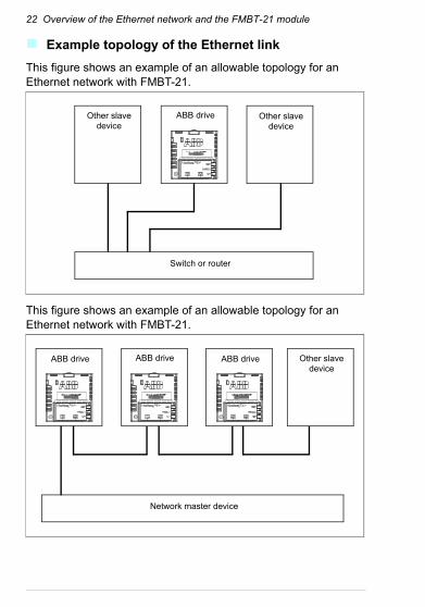
Example topology of the Ethernet link
This figure shows an example of an allowable topology for an Ethernet network with FMBT-21.
This figure shows an example of an allowable topology for an Ethernet network with FMBT-21.
Switch or router
ABB drive Other slave device
Other slave device
ABB drive
Network master device
ABB drive ABB drive Other slave device
Overview of the Ethernet network and the FMBT-21 module 23
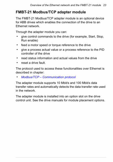
FMBT-21 Modbus/TCP adapter module
The FMBT-21 Modbus/TCP adapter module is an optional device for ABB drives which enables the connection of the drive to an Ethernet network.
Through the adapter module you can:
• give control commands to the drive (for example, Start, Stop, Run enable)
• feed a motor speed or torque reference to the drive
• give a process actual value or a process reference to the PID controller of the drive
• read status information and actual values from the drive
• reset a drive fault.
The protocol used to access these functionalities over Ethernet is described in chapter:
• Modbus/TCP – Communication protocol
The adapter module supports 10 Mbit/s and 100 Mbit/s data transfer rates and automatically detects the data transfer rate used in the network.
The adapter module is installed into an option slot on the drive control unit. See the drive manuals for module placement options.

24 Overview of the Ethernet network and the FMBT-21 module
Layout of the adapter module
This figure shows the layout of the FMBT-21 module.
No. Description See chapter
1 Lock Mechanical installation
2 Mounting screw Mechanical installation
3 Connector X1 to Ethernet Electrical installation
4 Connector X2 for chaining another adapter module
Electrical installation
5 Diagnostic LEDs Modbus/TCP – DiagnosticsNONE – Diagnostics
6 MAC ID
5
3
2
4
1
6

Mechanical installation 25
4Mechanical installation
Contents of this chapter
This chapter contains a delivery checklist and instructions to install the adapter module.
Necessary tools and instructions
You will need a Torx TX10 screwdriver to secure the FMBT-21 adapter module to the drive. See also, the applicable drive hardware manual.
Unpacking and examining the delivery
1. Open the option package.
2. Make sure that the package contains:
• Ethernet adapter module, type FMBT-21
• quick installation and start-up guide.
3. Make sure that there are no signs of damage.
26 Mechanical installation
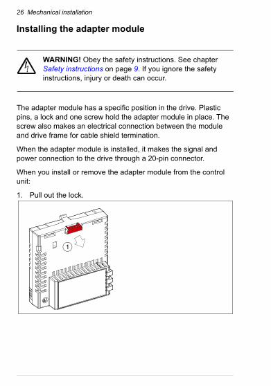
Installing the adapter module
WARNING! Obey the safety instructions. See chapter Safety instructions on page 9. If you ignore the safety instructions, injury or death can occur.
The adapter module has a specific position in the drive. Plastic pins, a lock and one screw hold the adapter module in place. The screw also makes an electrical connection between the module and drive frame for cable shield termination.
When the adapter module is installed, it makes the signal and power connection to the drive through a 20-pin connector.
When you install or remove the adapter module from the control unit:
1. Pull out the lock.
1

Mechanical installation 27
2. Install the module carefully to an option module slot of the drive. See the drive hardware manual.
3. Push in the lock.
4. Tighten the screw to torque 0.8 N·m using a Torx TX10 screwdriver.
WARNING! Do not use excessive force, or leave the screw too loose. Over-tightening can damage the screw or module. A loose screw decreases the EMC performance,
and can even cause an operation failure.
See the applicable drive manual for further instructions on how to install the adapter module to the drive.
3
4

28 Mechanical installation
Electrical installation 29
5Electrical installation
Contents of this chapter
This chapter contains:
• general cabling instructions
• instructions on connecting the adapter module to the Ethernet network.
Warnings
WARNING! Obey the safety instructions. See chapter Safety instructions on page 9. If you ignore the safety instructions, injury or death can occur. If you are not a
qualified electrician, do not do electrical work.
Necessary tools and instructions
See the applicable drive hardware manual.

30 Electrical installation
General cabling instructions• Arrange the bus cables as far away from the motor cables as
possible.
• Avoid parallel runs.
• Use bushings at cable entries.
Connecting the adapter module to the Ethernet network
The network cable can be CAT5 or higher, and type UTP, FTP or STP.
When CAT5 FTP or STP is used, the cable shield is connected to the drive frame through an RC network.
Connection procedure
1. Connect the network cable to the RJ-45 connector (X1) on the adapter module.
2. If you want to create a daisy chain with FMBT-21 adapter modules, connect the X2 connector of the first adapter module to X1 on the next adapter module, and so on.
Note: If a device in the daisy chain is powered off or fails, the rest of the chain is disconnected from the network.

Modbus/TCP protocol
Modbus/TCP – Start-up . . . . . . . . . . . . . . . . . . . . . . . . . . . . . . . 33
Modbus/TCP – Communication profiles . . . . . . . . . . . . . . . . . . . 55
Modbus/TCP – Communication protocol . . . . . . . . . . . . . . . . . . 65
Modbus/TCP – Diagnostics . . . . . . . . . . . . . . . . . . . . . . . . . . . . 77


Modbus/TCP – Start-up 33
7Modbus/TCP – Start-up
Contents of this chapter
This chapter contains:
• information on configuring the drive for operation with the adapter module
• drive-specific instructions on starting up the drive with the adapter module
• information on configuring the client for communication with the adapter module.
Warnings
WARNING! Obey the safety instructions given in this manual and the drive documentation.

34 Modbus/TCP – Start-up
Drive configuration
The information in this section applies to all drive types compatible with the adapter module, unless otherwise stated.
Modbus/TCP connection configuration
After the adapter module has been mechanically and electrically installed according to the instructions in chapters Mechanical installation and Electrical installation, you must prepare the drive for communication with the module.
The detailed procedure of activating the module for Modbus/TCP communication with the drive depends on the drive type. Normally, you must adjust a parameter to activate the communication. See the drive-specific start-up sections starting on page 46.
Once communication between the drive and the adapter module is established, several configuration parameters are copied to the drive. These parameters are shown in the tables below and must be checked first and adjusted where necessary. You can adjust the parameters via a drive control panel, a PC tool or a web user interface.
Note:
• Not all drives display descriptive names for the configuration parameters.
• The new parameter settings take effect only when you power up the module the next time or when you activate the fieldbus adapter refresh parameter 51.27 FBA A par refresh.

Modbus/TCP – Start-up 35
FMBT-21 configuration parameters – group A (group 1)
Note: The actual parameter group number depends on the drive type. Group A (group 1) corresponds to:
• parameter group 51 in ACS380, ACS480, ACS580, ACH580 and ACQ580.
• parameter group is typically 51/54 (group 151/154 in some variants) in ACS880 if the adapter is installed as fieldbus adapter A/B.
No. Name/Value Description Default
01 FBA type Read-only. Shows the fieldbus adapter type as detected by the drive. The value cannot be adjusted by the user. If the value is 0 = None, the communication between the drive and the module has not been established.
Modbus/ TCP
02 Protocol/Profile Selects the application protocol and communication profile for the network connection.The selections available for Modbus communication are listed below.
0 = MB/TCP ABB C
0 = MB/TCP ABB C Modbus/TCP: ABB Drives profile - Classic
1 = MB/TCP ABB E Modbus/TCP: ABB Drives profile - Enhanced
2 = MB/TCP T16 Modbus/TCP: Transparent 16-bit profile
3 = MB/TCP T32 Modbus/TCP: Transparent 32-bit profile
4 = MB/UDP ABB C Modbus over UDP: ABB Drives profile - Classic
5 = MB/UDP ABB E Modbus over UDP: ABB Drives profile - Enhanced
6 = MB/UDP T16 Modbus over UDP: Transparent 16-bit profile
7 = MB/UDP T32 Modbus over UDP: Transparent 32-bit profile
03 Commrate Sets the bit rate for the Ethernet interface. 0 = Auto
0 = Auto Auto-negotiate
1 = 100 Mbps FD 100 Mbps, full duplex
2 = 100 Mbps HD 100 Mbps, half duplex
3 = 10 Mbps FD 10 Mbps, full duplex
4 = 10 Mbps HD 10 Mbps, half duplex

36 Modbus/TCP – Start-up
04 IP configuration Sets the method for configuring the IP address, subnet mask and gateway address for the module.
1 = Dyn IP DHCP
0 = Static IP Configuration will be obtained from parameters 05…13.
1 = Dyn IP DHCP Configuration will be obtained via DHCP.
05 IP address 1 An IP address is assigned to each IP node on a network. An IP address is a 32-bit number that is typically represented in “dotted decimal” notation consisting of four decimal integers, on the range 0…255, separated by periods. Each integer represents the value of one octet (8-bits) in the IP address. Parameters 05...08 define the four octets of the IP address.
0
0…255 IP address
… … … …
08 IP address 4 See parameter 05 IP address 1. 0
0…255 IP address
No. Name/Value Description Default

Modbus/TCP – Start-up 37
09 Subnet CIDR Subnet masks are used for splitting networks into smaller networks called subnets. A subnet mask is a 32-bit binary number that splits the IP address into a network address and host address. Subnet masks are typically represented in either dotted decimal notation or the more compact CIDR notation, as shown in the table below.
0
1…31 Subnet mask in CIDR notation
10 GW address 1 IP gateways connect individual physical IP subnets into a unified IP network. When an IP node needs to communicate with an IP node on another subnet, the IP node sends the data to the IP gateway for forwarding. Parameters 10…13 define the four octets of the gateway address.
0
0…255 GW address
… … … …
13 GW address 4 See parameter 10 GW address 1. 0
No. Name/Value Description Default
Dotted decimal CIDR Dotted decimal CIDR
255.255.255.254 31 255.254.0.0 15
255.255.255.252 30 255.252.0.0 14
255.255.255.248 29 255.248.0.0 13
255.255.255.240 28 255.240.0.0 12
255.255.255.224 27 255.224.0.0 11
255.255.255.192 26 255.224.0.0 10
255.255.255.128 25 255.128.0.0 9
255.255.255.0 24 255.0.0.0 8
255.255.254.0 23 254.0.0.0 7
255.255.252.0 22 252.0.0.0 6
255.255.248.0 21 248.0.0.0 5
255.255.240.0 20 240.0.0.0 4
255.255.224.0 19 224.0.0.0 3
255.255.192.0 18 192.0.0.0 2
255.255.128.0 17 128.0.0.0 1
255.255.0.0 16
38 Modbus/TCP – Start-up
0…255 GW address
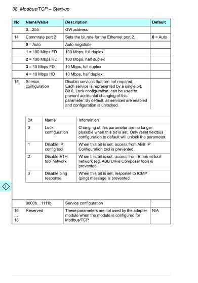
14 Commrate port 2 Sets the bit rate for the Ethernet port 2. 0 = Auto
0 = Auto Auto-negotiate
1 = 100 Mbps FD 100 Mbps, full duplex
2 = 100 Mbps HD 100 Mbps, half duplex
3 = 10 Mbps FD 10 Mbps, full duplex
4 = 10 Mbps HD 10 Mbps, half duplex
15 Service configuration
Disable services that are not required.Each service is represented by a single bit.Bit 0, Lock configuration, can be used to prevent accidental changing of thisparameter. By default, all services are enabled and configuration is unlocked.
0000b…1111b Service configuration
16…18
Reserved These parameters are not used by the adapter module when the module is configured for Modbus/TCP.
N/A
No. Name/Value Description Default
Bit Name Information
0 Lock configuration
Changing of this parameter are no longerpossible when this bit is set. Only reset fieldbus configuration to default will unlock the parameter.
1 Disable IP config tool
When this bit is set, access from ABB IPConfiguration tool is prevented.
2 Disable ETH tool network
When this bit is set, access from Ethernet tool network (eg, ABB Drive Composer tool) is prevented.
3 Disable ping response
When this bit is set, response to ICMP(ping) message is prevented.

Modbus/TCP – Start-up 39
19 T16 scale Defines the reference multiplier/actual value divisor for the adapter module. Note: The parameter is effective only when the following conditions are satisfied:• transparent 16 profile is selected• drive is using the native communication
profile (e.g, DCU or FBA) • drive is using a 16-bit transparent
reference 1/actual value 1.Reference 1 is multiplied by the value of this plus one and the actual value 1 is divided by the value of this plus one. With value 0, the reference 1/actual value 1 scale in the adapter module is 1 = 1. With ACS380, ACx580 and ACS880: Generic reference type:1 = (T16 scale + 1)/100 -> T16 scale = 99, 1 = 1.
99
0…65535 Reference multiplier/actual value divisor
20 Timeout time Defines the Modbus/TCP timeout value. The Modbus protocol does not specify a timeout mechanism for the application layer. A timeout mechanism may be desired when controlling a drive, so the adapter module provides a method for this purpose.• If the parameter value is zero, this feature
is disabled.• If the parameter value is non-zero, the
timeout is:
For example, a value of 22 results in a timeout of:
If a timeout occurs, the adapter module signals the drive that communication with the client has been lost. The drive configuration then determines how to respond. Example: If the Modbus/TCP timeout is 300 ms and the drive is configured to fault on a communication failure with a delay of 500 ms, the drive will fault 800 ms after communications is lost.
20
0…65535 Modbus/TCP timeout value
No. Name/Value Description Default
(Modbus/TCP timeout value) * 100 milliseconds
22 * 100 milliseconds = 2.2 seconds
40 Modbus/TCP – Start-up
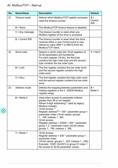
21 Timeout mode Selects which Modbus/TCP register accesses reset the timeout counter.
2 = Control WR
0 = None The Modbus/TCP timeout feature is disabled.
1 = Any message The timeout counter is reset when any Modbus register of the drive is accessed.
2 = Control RW The timeout counter is reset when the drive receives either a new Control word or new reference value (REF1 or REF2) from the Modbus/TCP client.
22 Word order Selects in which order the 16-bit registers of 32-bit parameters are transferred. For each register (16-bit), the first byte contains the high order byte and the second byte contains the low order byte.
1 = HILO
0 = LoHi The first register contains the low order word and the second register contains the high order word.
1 = HiLo The first register contains the high order word and the second register contains the low order word.
23 Address mode Defines the mapping between parameters and holding registers in the 0...65535 Modbus register range.
0 = Mode 0
0 = Mode 0 Used when access to parameter indexes greater than 99 is not needed. Allows 5-digit addressing1) used by legacy Modbus masters.16-bit access:1)
Register address2) = 100 * parameter group + parameter index (16-bit values, groups 1...199, indexes 1...99)32-bit access:Register address = 20000 + 200 * parameter group + 2 * parameter index (32-bit values, groups 1...199, indexes 1...99)
1 = Mode 1 16-bit access:Register address = 256 * parameter group + parameter index(16-bit values, groups 1...255, indexes 1...255)Example: 13057 (0x3301) is group 51 index 1No access to 32-bit parameter values.
No. Name/Value Description Default
Modbus/TCP – Start-up 41
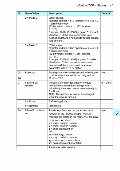
2 = Mode 2 32-bit access:Register address = 512 * parameter group + 2 * parameter index(32-bit values, groups 1...127, indexes 1...255).Example: 26114 (0x6602) is group 51 index 1Used when 32-bit parameter values are needed and there is no need to access groups 128 or higher.
3 = Mode 3 32-bit access:Register address = 256 * parameter group + 2 * parameter index(32-bit values, groups 1...255, indexes 1...127).Example: 13058 (0x3302) is group 51 index 1Used when 32-bit parameter values are needed and there is no need to access parameter index 128 or higher.
24…26
Reserved These parameters are not used by the adapter module when the module is configured for Modbus/TCP.
N/A
27 FBA A/B par refresh
Validates any changed adapter module configuration parameter settings. After refreshing, the value reverts automatically to 0 = Done.Note: This parameter cannot be changed while the drive is running.
0 = Done
0 = Done Refreshing done
1 = Refresh Refreshing
28 FBA A/B par table ver
Read-only. Displays the parameter table revision of the fieldbus adapter module mapping file stored in the memory of the drive.In format xyz, where x = major revision numbery = minor revision numberz = correction numberORin format axyz, where a = major revision numberxy = minor revision numbersz = correction number or letter.
N/A
Parameter table revision
No. Name/Value Description Default
42 Modbus/TCP – Start-up
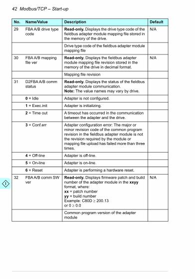
29 FBA A/B drive type code
Read-only. Displays the drive type code of the fieldbus adapter module mapping file stored in the memory of the drive.
N/A
Drive type code of the fieldbus adapter module mapping file
30 FBA A/B mapping file ver
Read-only. Displays the fieldbus adapter module mapping file revision stored in the memory of the drive in decimal format.
N/A
Mapping file revision
31 D2FBA A/B comm status
Read-only. Displays the status of the fieldbus adapter module communication.Note: The value names may vary by drive.
0 = Idle Adapter is not configured.
1 = Exec.init Adapter is initializing.
2 = Time out A timeout has occurred in the communication between the adapter and the drive.
3 = Conf.err Adapter configuration error: The major or minor revision code of the common program revision in the fieldbus adapter module is not the revision required by the module or mapping file upload has failed more than three times.
4 = Off-line Adapter is off-line.
5 = On-line Adapter is on-line.
6 = Reset Adapter is performing a hardware reset.
32 FBA A/B comm SW ver
Read-only. Displays firmware patch and build number of the adapter module in the xxyy format, where:xx = patch numberyy = build numberExample: C80D 200.13 or 0 0.0
N/A
Common program version of the adapter module
No. Name/Value Description Default
Modbus/TCP – Start-up 43
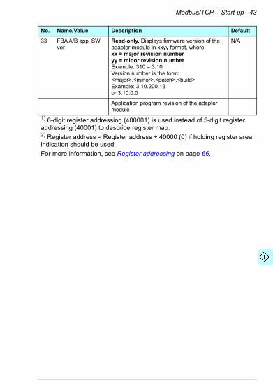
33 FBA A/B appl SW ver
Read-only. Displays firmware version of the adapter module in xxyy format, where:xx = major revision numberyy = minor revision numberExample: 310 = 3.10Version number is the form: <major>.<minor>.<patch>.<build>Example: 3.10.200.13or 3.10.0.0
N/A
Application program revision of the adapter module
1) 6-digit register addressing (400001) is used instead of 5-digit register addressing (40001) to describe register map.2) Register address = Register address + 40000 (0) if holding register area indication should be used.
For more information, see Register addressing on page 66.
No. Name/Value Description Default

44 Modbus/TCP – Start-up
FMBT-21configuration parameters – group B (group 2)
Note: The actual parameter group number depends on the drive type. Group B (group 2) corresponds to:
• parameter group 53 in ACS380, ACS480, ACS580, ACH580, and ACQ580
• parameter group is typically 53/56 (group 153/156 in some variants) in ACS880 if the adapter is installed as fieldbus adapter A/B.
No.1) Name/Value Description Default
01 FBA A/B data out1(client to drive)
Selects the drive parameter address into which the value of the Data out 1 register is written (from the client to the server). The Modbus register address maps are explained in chapter Modbus/TCP – Communication protocol. The content is defined by a decimal number in the range of 0 to 9999 as follows:
0 = None
0 = None Not used
101…9999 Parameter index with format xxyy, where• xx is the parameter group number (1…99) • yy is the parameter number index within
that group (01…99).Note: In ACS480, ACS580 and ACS880, choose Other to display a list of mappable drive parameters.
02…12
Data out 2 …Data out 12
See parameter 01 FBA A/B data out1. 0 = None
1) The number of parameters in this group may vary by drive type and drive firmware.
0 Not used
1…99 Virtual address area of drive control. Not used when the Modbus/TCP protocol is used.
101…9999
Parameter area of the drive

Modbus/TCP – Start-up 45
FMBT-21 configuration parameters – group C (group 3)
Note: The actual parameter group number depends on the drive type. Group C (group 3) corresponds to:
• parameter group 52 in ACS480, ACS580, ACH580 and ACQ580.
• parameter group is typically 52/55 (group 152/155 in some variants) in ACS880 if the adapter is installed as fieldbus adapter A/B.
No.1) Name/Value Description Default
01 FBA A/B data in1
(drive to client)
Selects the drive parameter address from which the data is read to the Data in 1 register (from the server to the client). The Modbus register address maps are explained in chapter Modbus/TCP – Communication protocol.The content is defined by a decimal number in the range of 0 to 9999 as follows:
0 = None
0 = None Not used
101…9999 Parameter index with format xxyy, where• xx is the parameter group number (1…99) • yy is the parameter number index within
that group (01…99).Note: In ACS480, ACS580 and ACS880, choose Other to display a list of mappable drive parameters.
02…12
Data in 2 …Data in 12
See parameter 01 FBA A/B data in1. 0 = None
1) The number of parameters in this group may vary by drive type and drive firmware.
0 Not used
1…99 Virtual address area of drive control. Not used when the Modbus/TCP protocol is used.
101…9999
Parameter area of the drive

46 Modbus/TCP – Start-up
Control locations
ABB drives can receive control information from multiple sources including digital inputs, analog inputs, the drive control panel and a fieldbus adapter module. ABB drives allow the user to separately determine the source for each type of control information (Start, Stop, Direction, Reference, Fault reset, etc.).
To give the fieldbus client the most complete control over the drive, you must select the adapter module as the source of this information. The drive-specific parameter setting examples below contain the drive control parameters relevant in the examples. For a complete parameter list, see the drive documentation.
Starting up fieldbus communication for ACS480, ACx580 and ACS880 drives
1. Power up the drive.
2. Enable the communication between the adapter module and the drive by selecting the correct slot number in parameter 50.01 FBA A enable.
The selection must correspond to the slot where the adapter module is installed. For example, if the adapter module is installed in slot 1, you must select slot 1.
3. With parameter 50.02 FBA A comm loss func, select how the drive reacts to a fieldbus communication break.
Note that this function monitors both communication between the fieldbus master and the adapter module and communication between the adapter module and the drive.
4. With parameter 50.03 FBA A comm loss t out, define the time between communication break detection and the selected action.
5. Select application-specific values for the rest of the parameters in group 50, starting from 50.04.
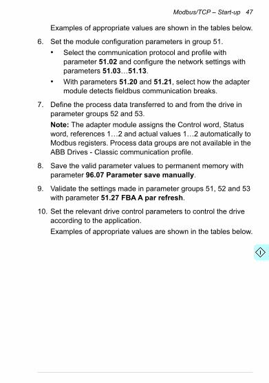
Modbus/TCP – Start-up 47
Examples of appropriate values are shown in the tables below.
6. Set the module configuration parameters in group 51.
• Select the communication protocol and profile with parameter 51.02 and configure the network settings with parameters 51.03…51.13.
• With parameters 51.20 and 51.21, select how the adapter module detects fieldbus communication breaks.
7. Define the process data transferred to and from the drive in parameter groups 52 and 53.
Note: The adapter module assigns the Control word, Status word, references 1…2 and actual values 1…2 automatically to Modbus registers. Process data groups are not available in the ABB Drives - Classic communication profile.
8. Save the valid parameter values to permanent memory with parameter 96.07 Parameter save manually.
9. Validate the settings made in parameter groups 51, 52 and 53 with parameter 51.27 FBA A par refresh.
10. Set the relevant drive control parameters to control the drive according to the application.
Examples of appropriate values are shown in the tables below.

48 Modbus/TCP – Start-up
Parameter setting examples – ACS480 and ACx580 drives
Frequency control using the ABB Drives – Enhanced communication profile
This example shows how to configure a frequency control application that uses the ABB Drives - Enhanced profile. In addition, some application-specific data is added to the communication.
The start/stop commands and reference are according to the ABB Drives profile. For more information, see section ABB Drives communication profile on page 57.
In the frequency control mode, when Reference 1 (REF1) is used, a reference value of ±20000 (4E20h) corresponds to the reference set with parameter 46.02 Frequency scaling in the forward and reverse directions.
The minimum and maximum 16-bit integer values that can be given through the fieldbus are -32768 and 32767 respectively.
The table below gives the recommended drive parameter settings.
Output data Modbus register
Input data Modbus register
Control word (4)00001 Status word (4)00051
Frequency reference (4)00002 Frequency actual value (4)00052
Reference 2 (Not used) (4)00003 Actual value 2 (Not used) (4)00053
Constant frequency 11) (4)00004(4)00005
Power1) (4)00054(4)00055
Constant frequency 21) (4)00006(4)00007
DC bus voltage1) (4)00056(4)00057
1) Example
Drive parameter Setting for ACS480 and ACS580 drives
Description
50.01 FBA A enable 1 = Enable Enables communication between the drive and the fieldbus adapter module.

Modbus/TCP – Start-up 49
50.02 FBA A comm loss func
1 = Fault2) Enables fieldbus A communication fault monitoring.
50.03 FBA A comm loss t out
3.0 s2) Defines the fieldbus A communication break supervision time.
50.04 FBA A ref1 type
0 = Speed or frequency
Selects the fieldbus A reference 1 type and scaling.
51.01 FBA A type Modbus/TCP1) Displays the type of the fieldbus adapter module.
51.02 Protocol/Profile 1 = MB/TCP ABB E Selects the Modbus/TCP protocol and the ABB Drives - Enhanced profile.
51.03 Commrate 0 = Auto2) Ethernet communication rate is negotiated automatically by the device.
51.04 IP configura-tion
0 = Static IP2) Configuration will be obtained from parameters 05…13.
51.05 IP address 1 1922) First part of the IP address
51.06 IP address 2 1682) Second part of the IP address
51.07 IP address 3 02) Third part of the IP address
51.08 IP address 4 162) Last part of the IP address
51.09 Subnet CIDR 242) Sets the network mask as 255.255.255.0, allowing access only to the last subnet.
51.20 Timeout time 102) Sets the communication timeout as 1 second.
51.21 Timeout mode 2 = Control RW2) The timeout feature monitors the updating of the Control word and Reference 1.
52.01 FBA A data in1 01.142) Output power
52.03 FBA a data in3 01.112) DC voltage
53.01 FBA A data out1
28.262) Constant frequency 1
53.03 FBA A data out3
28.272) Constant frequency 2
51.27 FBA A par refresh
1 = Refresh Validates the FMBT-21 configuration parameter settings.
Drive parameter Setting for ACS480 and ACS580 drives
Description

50 Modbus/TCP – Start-up
The start sequence for the parameter example above is given below.
Control word:
• Reset the fieldbus communication fault (if active).
• Enter 47Eh (1150 decimal) READY TO SWITCH ON.
Enter 47Fh (1151 decimal) OPERATING (Scalar motor control mode).
20.01 Ext1 commands
12 = Fieldbus A Selects the fieldbus A interface as the source of the start and stop commands for external control location 1.
22.11 Speed ref1 source
4 = FB A ref1 Selects the fieldbus A reference 1 as the source for speed reference 1.
31.11 Fault reset selection
06.1.7 Selects the fieldbus interface asthe source for the fault resetsignal.
1) Read-only or automatically detected/set2) Example
Drive parameter Setting for ACS480 and ACS580 drives
Description
Modbus/TCP – Start-up 51
Parameter setting examples – ACS880
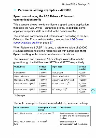
Speed control using the ABB Drives – Enhanced communication profile
This example shows how to configure a speed control application that uses the ABB Drives - Enhanced profile. In addition, some application-specific data is added to the communication.
The start/stop commands and reference are according to the ABB Drives profile. For more information, see section ABB Drives communication profile on page 57.
When Reference 1 (REF1) is used, a reference value of ±20000 (4E20h) corresponds to the reference set with parameter 46.01 Speed scaling in the forward and reverse directions.
The minimum and maximum 16-bit integer values that can be given through the fieldbus are -32768 and 32767 respectively.
The table below gives the recommended drive parameter settings.
Output data Modbus register
Input data Modbus register
Control word (4)00001 Status word (4)00051
Speed reference (4)00002 Speed actual value (4)00052
Reference 2 (Not used) (4)00003 Actual value 2 (Not used) (4)00053
Constant speed 1 [32]1) (4)00004(4)00005
Output power [32]1) (4)00054(4)00055
Constant speed 2 [32]1) (4)00006(4)00007
DC voltage [32]1) (4)00056(4)00057
1) Example
Drive parameter Setting for ACS880 drives
Description
50.01 FBA A enable 1 = Option slot 12) Enables communication between the drive and the fieldbus adapter module.
50.02 FBA A comm loss func
1 = Fault2) Enables fieldbus A communication fault monitoring.

52 Modbus/TCP – Start-up
50.03 FBA A comm loss t out
3.0 s2) Defines the fieldbus A communication break supervision time.
50.04 FBA A ref1 type 4 = Speed Selects the fieldbus A reference 1 type and scaling.
51.01 FBA A type Modbus/TCP1) Displays the type of the fieldbus adapter module.
51.02 Protocol/Profile 1 = MB/TCP ABB E Selects the Modbus/TCP protocol and the ABB Drives - Enhanced profile.
51.03 Commrate 0 = Auto2) Ethernet communication rate is negotiated automatically by the device.
51.04 IP configuration 0 = Static IP2) Configuration will be obtained from parameters 05…13.
51.05 IP address 1 1922) First part of the IP address
51.06 IP address 2 1682) Second part of the IP address
51.07 IP address 3 02) Third part of the IP address
51.08 IP address 4 162) Last part of the IP address
51.09 Subnet CIDR 242) Sets the network mask as 255.255.255.0, allowing access only to the last subnet.
51.20 Timeout time 102) Sets the communication timeout as 1 second.
51.21 Timeout mode 2 = Control RW2) The timeout feature monitors the updating of the Control word and Reference 1.
52.01 FBA A data in1 01.142) Output power
52.03 FBA a data in3 01.112) DC voltage
53.01 FBA A data out1 22.262) Constant speed 1
53.03 FBA A data out3 22.272) Constant speed 2
51.27 FBA A par refresh 1 = Refresh Validates the FMBT-21 configuration parameter settings.
Drive parameter Setting for ACS880 drives
Description

Modbus/TCP – Start-up 53
The start sequence for the parameter example above is given below.
Control word:
• Reset the fieldbus communication fault (if active).
• Enter 47Eh (1150 decimal) READY TO SWITCH ON.
• Enter 47Fh (1151 decimal) OPERATING (Speed mode).
20.01 Ext1 commands 12 = Fieldbus A Selects the fieldbus A interface as the source of the start and stop commands for external control location 1.
22.11 Speed ref1 source 4 = FB A ref1 Selects the fieldbus A reference 1 as the source for speed reference 1.
31.11 Fault reset selection
30 = FBA A MCW bit 7 Selects the fieldbus interface as the source for the fault reset signal.
1) Read-only or automatically detected/set2) Example
Drive parameter Setting for ACS880 drives
Description

54 Modbus/TCP – Start-up
Client configuration
After the adapter module has been initialized by the drive, you must prepare the client for communication with the module. Due to the large number of different Modbus clients, specific instructions cannot be provided here. Refer to the documentation of your client for more information.
Modbus register maps
The Modbus register map which the adapter module presents to the Modbus client is selected with parameter 02 Protocol/Profile (see page 35).
For Modbus register map definitions, see chapter Modbus/TCP – Communication protocol.
For definitions of the Control word, Status word, references and actual values for a given communication profile, see chapter Modbus/TCP – Communication profiles.

Modbus/TCP – Communication profiles 55
8Modbus/TCP – Communication profiles
Contents of this chapter
This chapter describes the communication profiles used in the communication between the Modbus/TCP client, the adapter module and the drive.
Communication profiles
Communication profiles are ways of conveying control commands (Control word, Status word, references and actual values) between the Modbus client and the drive.
With the FMBT-21 adapter module, the Modbus/TCP network may employ either the ABB Drives profile or one of two Transparent modes for 16-bit and 32-bit words respectively. For the ABB Drives profile, data is converted by the adapter module into the native profile (eg, DCU or FBA). For the Transparent modes, no data conversion takes place.

56 Modbus/TCP – Communication profiles
The figure below illustrates the profile selection:
The following sections describe the Control word, the Status word, references and actual values for the ABB Drives communication profile. Refer to the drive manuals for details on the native profiles.
FMBT-21 Drive
Profile selection:
ABB Drives profile
Native profile
Data conversion
ABB Drives
Drive-specific profile1)
(with 16-bit words)
Transparent32Drive-specific profile1)
(with 32-bit words)
Modbus/TCP network
1) Can be used if the native profile is supported by the drive.
Transparent16
Optional reference/actual value scaling

Modbus/TCP – Communication profiles 57
ABB Drives communication profile
Control word and Status word
The Control word is the principal means for controlling the drive from a fieldbus system. It is sent by the fieldbus client station to the drive through the adapter module. The drive switches between its states according to the bit-coded instructions in the Control word and returns status information to the client in the Status word.
The contents of the Control word and the Status word are detailed below. The drive states are presented on page 61.
Control word contents
The table below shows the contents of the Control word for the ABB Drives communication profile. The upper case boldface text refers to the states shown in the state machine on page 61.
Bit Name Value STATE/Description
0 OFF1_CONTROL
1 Proceed to READY TO OPERATE.
0 Stop along currently active deceleration ramp. Proceed to OFF1 ACTIVE; proceed to READY TO SWITCH ON unless other interlocks (OFF2, OFF3) are active.
1 OFF2_CONTROL
1 Continue operation (OFF2 inactive).
0 Emergency OFF, coast to stop.Proceed to OFF2 ACTIVE, proceed to SWITCH-ON INHIBITED.
2 OFF3_CONTROL
1 Continue operation (OFF3 inactive).
0 Emergency stop, stop within time defined by drive parameter. Proceed to OFF3 ACTIVE; proceed to SWITCH-ON INHIBITED.Warning: Ensure that motor and driven machine can be stopped using this stop mode.

58 Modbus/TCP – Communication profiles
3 INHIBIT_OPERATION
1 Proceed to OPERATION ENABLED.Note: Run enable signal must be active; see drive documentation. If the drive is set to receive the Run enable signal from the fieldbus, this bit activates the signal.
0 Inhibit operation. Proceed to OPERATION INHIBITED.
4 RAMP_OUT_ZERO
1 Normal operation. Proceed to RAMP FUNCTION GENERATOR: OUTPUT ENABLED.
0 Force Ramp Function Generator output to zero. Drive ramps to stop (current and DC voltage limits in force).
5 RAMP_HOLD 1 Enable ramp function.Proceed to RAMP FUNCTION GENERATOR: ACCELERATOR ENABLED.
0 Halt ramping (Ramp Function Generator output held).
6 RAMP_IN_ZERO
1 Normal operation. Proceed to OPERATION.Note: This bit is effective only if the fieldbus interface is set as the source for this signal by drive parameters.
0 Force Ramp Function Generator input to zero.
7 RESET 0 1 Fault reset if an active fault exists. Proceed to SWITCH-ON INHIBITED.Note: This bit is effective only if the fieldbus interface is set as the source for this signal by drive parameters.
0 Continue normal operation.
8…9 Reserved.
10 REMOTE_CMD
1 Fieldbus control enabled.
0 Control word and reference not getting through to the drive, except for CW bits OFF1, OFF2 and OFF3.
11 EXT_CTRL_LOC
1 Select External Control Location EXT2. Effective if control location parameterized to be selected from fieldbus.
0 Select External Control Location EXT1. Effective if control location parameterized to be selected from fieldbus.
12…15
Reserved or freely programmable control bits
Bit Name Value STATE/Description

Modbus/TCP – Communication profiles 59
Status word contents
The table below shows the contents of the Status word for the ABB Drives communication profile. The upper case boldface text refers to the states shown in the state machine on page 61.
Bit Name Value STATE/Description
0 RDY_ON 1 READY TO SWITCH ON
0 NOT READY TO SWITCH ON
1 RDY_RUN 1 READY TO OPERATE
0 OFF1 ACTIVE
2 RDY_REF 1 OPERATION ENABLED
0 OPERATION INHIBITED
3 TRIPPED 1 FAULT
0 No fault
4 OFF_2_STA 1 OFF2 inactive
0 OFF2 ACTIVE
5 OFF_3_STA 1 OFF3 inactive
0 OFF3 ACTIVE
6 SWC_ON_INHIB
1 SWITCH-ON INHIBITED
0 –
7 ALARM 1 Warning/Alarm
0 No warning/alarm
8 AT_SETPOINT
1 OPERATION. Actual value equals reference (= is within tolerance limits, i.e., in speed control, speed error is 10% max. of nominal motor speed).
0 Actual value differs from reference (= is outside tolerance limits.)
9 REMOTE 1 Drive control location: REMOTE (EXT1 or EXT2)
0 Drive control location: LOCAL
10 ABOVE_LIMIT
1 Actual frequency or speed equals or exceeds supervision limit (set by drive parameter). Valid in both directions of rotation.
0 Actual frequency or speed within supervision limit
11 EXT_CTRL_LOC
1 External Control Location EXT2 selected.Note concerning ACS880: This bit is effective only if the fieldbus interface is set as the target for this signal by drive parameters. User bit 0 selection (06.33)
0 External Control Location EXT1 selected
60 Modbus/TCP – Communication profiles
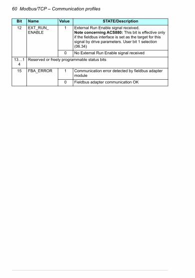
12 EXT_RUN_ENABLE
1 External Run Enable signal received.Note concerning ACS880: This bit is effective only if the fieldbus interface is set as the target for this signal by drive parameters. User bit 1 selection (06.34)
0 No External Run Enable signal received
13…14
Reserved or freely programmable status bits
15 FBA_ERROR 1 Communication error detected by fieldbus adapter module
0 Fieldbus adapter communication OK
Bit Name Value STATE/Description

Modbus/TCP – Communication profiles 61
State machine
The state machine for the ABB Drives communication profile is shown below.
MAINS OFF
Power ON (CW Bit0=0)
(SW Bit6=1)
(SW Bit0=0)
from any state
(CW=xxxx x1xx xxxx x110)
(SW Bit1=1)
n(f)=0 / I=0
(SW Bit2=0)
A B C D
(CW Bit3=0)
operationinhibited
OFF1 (CW Bit0=0)
(SW Bit1=0)
(SW Bit0=1)
(CW Bit3=1and
SW Bit12=1)
C D
(CW Bit5=0)
(SW Bit2=1)
(SW Bit5=0)
from any state from any state
Emergency stopOFF3 (CW Bit2=0)
n(f)=0 / I=0
Emergency OFFOFF2 (CW Bit1=0)
(SW Bit4=0)
B
B C D
(CW Bit4=0)
(CW=xxxx x1xx xxx1 1111)
(CW=xxxx x1xx xx11 1111)
D
(CW Bit6=0)
A
C(CW=xxxx x1xx x111 1111)
(SW Bit8=1)D
from any state
Fault
(SW Bit3=1)
(CW Bit7=1)
(CW=xxxx x1xx xxxx x111)
(CW=xxxx x1xx xxxx 1111and SW Bit12=1)
ABB Drivescommunication
profile
SWITCH-ON INHIBITED
NOT READY TO SWITCH ON
READY TO SWITCH ON
READY TO OPERATE
OPERATION INHIBITED
OFF1 ACTIVE
OPERATION ENABLED
RFG: OUTPUT ENABLED
RFG: ACCELERATOR ENABLED
OPERATION
OFF2 ACTIVE
FAULT
OFF3 ACTIVE
state
condition
rising edgethe bitof
CW = Control wordSW = Status wordn = SpeedI = Input currentRFG = Ramp function
generatorf = Frequency
62 Modbus/TCP – Communication profiles
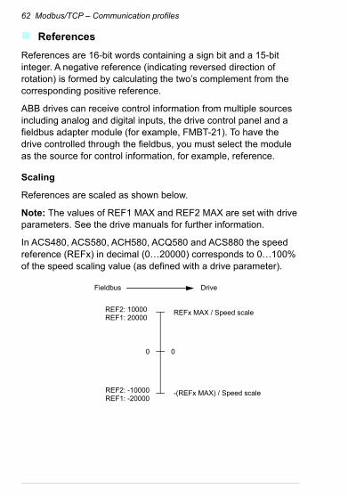
References
References are 16-bit words containing a sign bit and a 15-bit integer. A negative reference (indicating reversed direction of rotation) is formed by calculating the two’s complement from the corresponding positive reference.
ABB drives can receive control information from multiple sources including analog and digital inputs, the drive control panel and a fieldbus adapter module (for example, FMBT-21). To have the drive controlled through the fieldbus, you must select the module as the source for control information, for example, reference.
Scaling
References are scaled as shown below.
Note: The values of REF1 MAX and REF2 MAX are set with drive parameters. See the drive manuals for further information.
In ACS480, ACS580, ACH580, ACQ580 and ACS880 the speed reference (REFx) in decimal (0…20000) corresponds to 0…100% of the speed scaling value (as defined with a drive parameter).
DriveFieldbus
0
REFx MAX / Speed scale
-(REFx MAX) / Speed scale
0
REF2: -10000REF1: -20000
REF2: 10000REF1: 20000

Modbus/TCP – Communication profiles 63
Actual values
Actual values are 16-bit words containing information on the operation of the drive. The functions to be monitored are selected with a drive parameter.
Scaling
Actual values are scaled as shown below.
Note: The values of REF1 MAX and REF2 MAX are set with drive parameters. See the drive manuals for further information.
0
REFx MAX/Speed scale
-(REFx MAX)/Speed scale
0
ACT2: -10000ACT1: -20000
ACT2: 10000ACT1: 20000
DriveFieldbus

64 Modbus/TCP – Communication profiles

Modbus/TCP – Communication protocol 65
9Modbus/TCP – Communication protocol
Contents of this chapter
This chapter describes the Modbus/TCP communication protocol for the adapter module.
Modbus/TCP
Modbus/TCP is a variant of the Modbus family of simple, vendor neutral communication protocols intended for supervision and control of automation equipment. Specifically, it covers the use of Modbus messaging over TCP connection on an IP network.
The FMBT-21 adapter module acts as a Modbus/TCP server with support for the ABB Drives and Transparent profiles. The adapter module also supports Modbus over UDP. The only difference between Modbus/TCP and Modbus/UDP is that in Modbus/UDP the transport layer protocol is UDP instead of TCP.
The supported Modbus commands are listed in section Function codes on page 66. Two simultaneous Modbus/TCP connections are supported, that is, two clients can be connected to the adapter module at a time.

66 Modbus/TCP – Communication protocol
For information of the port used with Modbus/TCP or Modbus/UDP, see TCP and UDP service ports on page 102.
Further information on the Modbus/TCP protocol is available at www.modbus.org.
Register addressing
The address field of Modbus Requests for accessing Holding registers is 16 bits. This allows the Modbus protocol to support addressing of 65536 Holding registers.
Historically, Modbus client devices used 5-digit decimal addresses from 40001 to 49999 to represent Holding register addresses. 5-digit decimal addressing limited to 9999 the number of holding registers that could be addressed.
Modern Modbus client devices typically provide a means to access the full range of 65536 Modbus Holding registers. One of these methods is to use 6-digit decimal addresses from 400001 to 465536. This manual uses 6-digit decimal addressing to represent Modbus Holding register addresses.
Modbus client devices that are limited to 5-digit decimal addressing may still access registers 400001 to 409999 by using 5-digit decimal addresses 40001 to 49999. Registers 410000-465536 are inaccessible to these clients.
Function codes
The adapter module supports the Modbus function codes shown below.
Function code Name Description
03h Read Holding Registers Reads the contents of a contiguous block of holding registers in a server device.
06h Write Single Register Writes a single holding register in a server device.
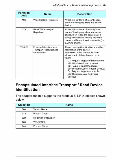
Modbus/TCP – Communication protocol 67
Encapsulated Interface Transport / Read Device Identification
The adapter module supports the Modbus EIT/RDI objects shown below.
10h Write Multiple Registers Writes the contents of a contiguous block of holding registers in a server device.
17h Read/Write Multiple Registers
Writes the contents of a contiguous block of holding registers in a server device, then reads the contents of a contiguous block of holding registers (same or different than those written) in a server device.
2Bh/0Eh Encapsulated Interface Transport / Read Device Identification
Allows reading identification and other information of the server.Parameter "Read Device ID code" allows one to define three access types:• 01: Request to get the basic device
identification (stream access)• 02: Request to get the regular
device identification (stream access)• 04: Request to get one specific
identification object (individual access).
Object ID Name
00h Vendor Name
01h Product Code
02h Major/Minor Revision
03h Vendor URL
04h Product Name
Function code Name Description

68 Modbus/TCP – Communication protocol
Exception codes
The adapter module supports the Modbus exception codes shown below.
Communication profiles
Modbus is an application layer messaging protocol. It describes how data is transferred between the client and a server, but not the meaning of that data. Communication profiles are used to define the meaning of the data.
Exception Code Name Description
01h ILLEGAL FUNCTION The function code received in the query is not an allowable action for the server.
02h ILLEGAL DATA ADDRESSS
The data address received in the query is to an allowable address for the server.
03h ILLEGAL DATA VALUE A value contained in the query data field is not an allowable value for the server.
04h SLAVE DEVICE FAILURE An unrecoverable error occurred while the server was attempting to perform the requested action.
06h SLAVE DEVICE BUSY The server is engaged in processing a long-duration command. The client should retransmit the message later when the server is free.

Modbus/TCP – Communication protocol 69
ABB Drives profile - Classic
The ABB Drives profile - Classic communication profile provides register mapped access to the control, status, reference and actual values of the ABB Drives profile in the classic format for backward compatibility.
Register Address1) Register Data (16-bit)
(4)00001 ABB Drives Profile Control
(4)00002 ABB Drives Profile Reference 1
(4)00003 ABB Drives Profile Reference 2
(4)00004 ABB Drives Profile Status
(4)00005 ABB Drive Profile Actual 1
(4)00006 ABB Drive Profile Actual 2
(4)00101…(4)09999 Drive Parameter Access (16-bit)Register Address = (4)00000 + 100 × Group + IndexExample for Drive Parameter 3.18:(4)00000 + 100 × 3 + 18 = 400318Note: Addressing depends on the address mode selected with parameter group 23 in group A (51/151, 54/154).
(4)20000…(4)29999 Drive Parameter Access (32-bit):Register Address = (4)20000 + 200 × Group + 2 × IndexExample for Drive Parameter 1.27:(4)20000 + 200 × 1 + 2 × 27 = 420254Note: Addressing depends on the address mode selected with parameter group 23 in group A (51/151, 54/154).
1) 6-digit register addressing ([4]00001) is used instead of 5-digit register addressing ([4]0001) to describe the register map. See section Register addressing on page 66 for additional information.

70 Modbus/TCP – Communication protocol
ABB Drives profile - Enhanced
The ABB Drives profile - Enhanced communication profile provides register mapped access to the control, status, reference and actual values of the ABB Drives profile. The mapping of the registers has been enhanced to allow writing of control and reading of status in a single Read/Write Multiple Register request.
Register Address 1), 2) Register Data (16-bit)
(4)00001 ABB Drives Profile Control
(4)00002 ABB Drives Profile Reference 1
(4)00003 ABB Drives Profile Reference 2
(4)00004 DATA OUT 1
(4)00005 DATA OUT 2
(4)00006 DATA OUT 3
(4)00007 DATA OUT 4
(4)00008 DATA OUT 5
(4)00009 DATA OUT 6
(4)00010 DATA OUT 7
(4)00011 DATA OUT 8
(4)00012 DATA OUT 9
(4)00013 DATA OUT 10
(4)00014 DATA OUT 11
(4)00015 DATA OUT 12
(4)00051 ABB Drives Profile Status
(4)00052 ABB Drive Profile Actual 1
(4)00053 ABB Drive Profile Actual 2
(4)00054 DATA IN 1
(4)00055 DATA IN 2
(4)00056 DATA IN 3
(4)00057 DATA IN 4
(4)00058 DATA IN 5
(4)00059 DATA IN 6
(4)00060 DATA IN 7
Modbus/TCP – Communication protocol 71
(4)00061 DATA IN 8
(4)00062 DATA IN 9
(4)00063 DATA IN 10
(4)00064 DATA IN 11
(4)00065 DATA IN 12
(4)00101…(4)09999 Drive Parameter Access (16-bit)Register Address = (4)00000 + 100 × Group + IndexExample for Drive Parameter 3.18:(4)00000 + 100 × 3 + 18 = 400318Note: Addressing depends on the address mode selected with parameter group 23 in group A (51/151, 54/154).
(4)20000…(4)29999 Drive Parameter Access (32-bit):Register Address = (4)20000 + 200 × Group + 2 × IndexExample for Drive Parameter 1.27:(4)20000 + 200 × 1 + 2 × 27 = 420254Note: Addressing depends on the address mode selected with parameter group 23 in group A (51/151, 54/154).
1) 6-digit register addressing ([4]00001) is used instead of 5-digit register addressing ([4]0001) to describe register map. See section Register addressing on page 66 for additional information.
2) Register addresses of the 32-bit parameters cannot be accessed by using 5-digit register numbers.
Register Address 1), 2) Register Data (16-bit)

72 Modbus/TCP – Communication protocol
Transparent 16-bit
The Transparent 16-bit communication profile provides unaltered 16-bit access to the configured drive profile.
Register Address 1), 2) Register Data (16-bit)
(4)00001 Native Drive Profile Control
(4)00002 Native Drive Profile Reference 1
(4)00003 Native Drive Profile Reference 2
(4)00004 DATA OUT 1
(4)00005 DATA OUT 2
(4)00006 DATA OUT 3
(4)00007 DATA OUT 4
(4)00008 DATA OUT 5
(4)00009 DATA OUT 6
(4)00010 DATA OUT 7
(4)00011 DATA OUT 8
(4)00012 DATA OUT 9
(4)00013 DATA OUT 10
(4)00014 DATA OUT 11
(4)00015 DATA OUT 12
(4)00051 Native Drive Profile Status
(4)00052 Native Drive Profile Actual 1
(4)00053 Native Drive Profile Actual 2
(4)00054 DATA IN 1
(4)00055 DATA IN 2
(4)00056 DATA IN 3
(4)00057 DATA IN 4
(4)00058 DATA IN 5
(4)00059 DATA IN 6
(4)00060 DATA IN 7
(4)00061 DATA IN 8
(4)00062 DATA IN 9
(4)00063 DATA IN 10
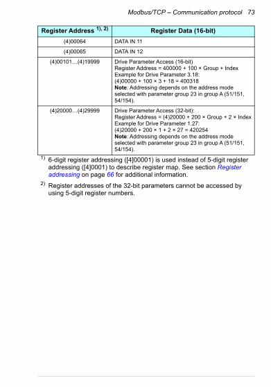
Modbus/TCP – Communication protocol 73
(4)00064 DATA IN 11
(4)00065 DATA IN 12
(4)00101…(4)19999 Drive Parameter Access (16-bit)Register Address = 400000 + 100 × Group + IndexExample for Drive Parameter 3.18:(4)00000 + 100 × 3 + 18 = 400318Note: Addressing depends on the address mode selected with parameter group 23 in group A (51/151, 54/154).
(4)20000…(4)29999 Drive Parameter Access (32-bit):Register Address = (4)20000 + 200 × Group + 2 × IndexExample for Drive Parameter 1.27:(4)20000 + 200 × 1 + 2 × 27 = 420254Note: Addressing depends on the address mode selected with parameter group 23 in group A (51/151, 54/154).
1) 6-digit register addressing ([4]00001) is used instead of 5-digit register addressing ([4]0001) to describe register map. See section Register addressing on page 66 for additional information.
2) Register addresses of the 32-bit parameters cannot be accessed by using 5-digit register numbers.
Register Address 1), 2) Register Data (16-bit)

74 Modbus/TCP – Communication protocol
Transparent 32-bit
The Transparent 32-bit communication profile provides unaltered 32-bit access to the configured drive profile.
Register Address 1), 2) Register Data (16-bit)
(4)00001 Native Drive Profile Control - Least Significant 16-bits
(4)00002 Native Drive Profile Control - Most Significant 16-bits
(4)00003 Native Drive Profile Reference 1 - Least Significant 16-bits
(4)00004 Native Drive Profile Reference 1 - Most Significant 16-bits
(4)00005 Native Drive Profile Reference 2 - Least Significant 16-bits
(4)00006 Native Drive Profile Reference 2 - Most Significant 16-bits
(4)00007 DATA OUT 1
(4)00008 DATA OUT 2
(4)00009 DATA OUT 3
(4)00010 DATA OUT 4
(4)00011 DATA OUT 5
(4)00012 DATA OUT 6
(4)00013 DATA OUT 7
(4)00014 DATA OUT 8
(4)00015 DATA OUT 9
(4)00016 DATA OUT 10
(4)00017 DATA OUT 11
(4)00018 DATA OUT 12
(4)00051 Native Drive Profile Status - Least Significant 16-bits
(4)00052 Native Drive Profile Status - Most Significant 16-bits
(4)00053 Native Drive Profile Actual 1 - Least Significant 16-bits
(4)00054 Native Drive Profile Actual 1 - Most Significant 16-bits
(4)00055 Native Drive Profile Actual 2 - Least Significant 16-bits
(4)00056 Native Drive Profile Actual 2 - Most Significant 16-bits
(4)00057 DATA IN 1
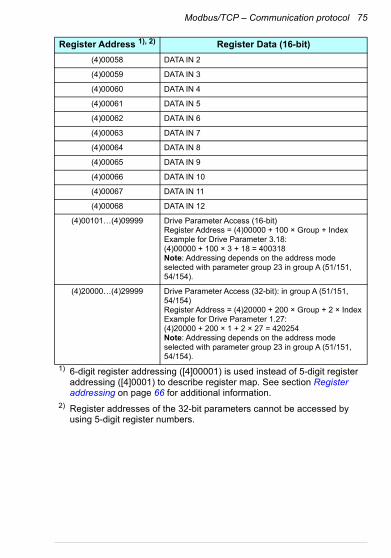
Modbus/TCP – Communication protocol 75
(4)00058 DATA IN 2
(4)00059 DATA IN 3
(4)00060 DATA IN 4
(4)00061 DATA IN 5
(4)00062 DATA IN 6
(4)00063 DATA IN 7
(4)00064 DATA IN 8
(4)00065 DATA IN 9
(4)00066 DATA IN 10
(4)00067 DATA IN 11
(4)00068 DATA IN 12
(4)00101…(4)09999 Drive Parameter Access (16-bit)Register Address = (4)00000 + 100 × Group + IndexExample for Drive Parameter 3.18:(4)00000 + 100 × 3 + 18 = 400318Note: Addressing depends on the address mode selected with parameter group 23 in group A (51/151, 54/154).
(4)20000…(4)29999 Drive Parameter Access (32-bit): in group A (51/151, 54/154)Register Address = (4)20000 + 200 × Group + 2 × IndexExample for Drive Parameter 1.27:(4)20000 + 200 × 1 + 2 × 27 = 420254Note: Addressing depends on the address mode selected with parameter group 23 in group A (51/151, 54/154).
1) 6-digit register addressing ([4]00001) is used instead of 5-digit register addressing ([4]0001) to describe register map. See section Register addressing on page 66 for additional information.
2) Register addresses of the 32-bit parameters cannot be accessed by using 5-digit register numbers.
Register Address 1), 2) Register Data (16-bit)

76 Modbus/TCP – Communication protocol
Modbus/TCP – Diagnostics 77
10Modbus/TCP – Diagnostics
Contents of this chapter
This chapter explains how to trace faults with the status LEDs on the adapter module when the module is used for Modbus/TCP communication.
Fault and warning messages
For the fault and warning messages concerning the adapter module, see the drive firmware manual.

78 Modbus/TCP – Diagnostics
LEDs
The adapter module is equipped with three bicolor diagnostic LEDs. The LEDs are described below.
Name Color Function
HOST
Blinking green Establishing communication to host
Green Connection to host OK
Blinking red Communication to host lost temporarily
Blinking orange, alternating with the MODULE blinking orange
Internal file system error. The error may be cleared by cycling drive power. If the error persists, contact your local ABB representative.
MODULE
Off There is no power applied to the device.
Flashing orange Device is attempting to obtain IP configuration from the DHCP server.
Orange Device is executing Duplicate Address Detection.
Flashing green Device is waiting for a Modbus request.
Green Device has received a Modbus request within the Modbus/TCP Timeout period.
Flashing red Ethernet link is down.
Red Ethernet interface is disabled. Duplicate Address Detection may have detected a duplicate address. Check the IP configuration and either initiate a Fieldbus Adapter parameter refresh or cycle power to the drive.
Flashing orange, alternating with the HOST flashing orange
Internal file system error. The error may be cleared by cycling drive power. If the error persists, contact your local ABB representative.

Modbus/TCP – Diagnostics 79
NETWORK/NET
Off Ethernet link is down.
Flashing green Ethernet link is up at 100 Mbps.Flashing indicates activity on interface.
Flashing orange Ethernet link is up at 10 Mbps.Flashing indicates activity on interface.
Name Color Function

80 Modbus/TCP – Diagnostics
Internal error code registers
A Modbus query can fail in many ways in the drive. The Modbus standard does not specify detailed error descriptions. In addition to the standard error codes, the FMBT-21 adapter module provides an internal error register area for more detailed diagnostics.
The internal error register area is used if Modbus error code 0x04 occurs. The registers contain information about the last query. You can figure out the reason of the failure by reading the registers. The internal error register is cleared when a query has finished successfully.
Address Registers (16-bit word)
(4)00090 Reset internal error registers (0 = Do nothing, 1 = Reset)
(4)00091 Function code of the failed query
(4)00092 Internal error code; see the error number.
(4)00093 Failed register
(4)00094 Last register that was written successfully
(4)00095 Last register that was read successfully
Error code Description Situation
0x00 No error Used when a Modbus query was successful
0x02 Low or high limit exceeded
Change access with a value outside the value limits
0x03 Faulty subindex Access to an unavailable subindex of an array parameter
0x05 Incorrect data type Change access with a value that does not match the data type of the parameter
0x65 General error in drive communication
Undefined error when handling a Modbus query
0x66 Timeout Timeout in drive communication when handling a Modbus query
0x70 Read-only An attempt to write a non-zero value to a read-only drive parameter

Modbus/TCP – Diagnostics 81
0x71 Parameter group ended An attempt to write to multiple parameter groups
0x72 MSB is not zero An attempt to write a 16-bit parameter with a 32-register address and the MSB bytes are not zero
0x73 LSB query start An attempt to access only the LSB register of the 32-bit parameter
0x74 MSB query end An attempt to access only the MSB register of the 32-bit parameter
Error code Description Situation

82 Modbus/TCP – Diagnostics

NONE protocol selection
NONE – Start-up. . . . . . . . . . . . . . . . . . . . . . . . . . . . . . . . . . . . . 85
NONE – Diagnostics . . . . . . . . . . . . . . . . . . . . . . . . . . . . . . . . . . 95


NONE – Start-up 85
12NONE – Start-up
Contents of this chapter
This chapter contains:
• information on configuring the drive for operation with the adapter module
• drive-specific instructions on starting up the drive with the adapter module
• information on configuring the client for communication with the adapter module.
Warnings
WARNING! Obey the safety instructions given in this manual and the drive documentation.

86 NONE – Start-up
Drive configuration
The information in this section applies to all drive types compatible with the adapter module, unless otherwise stated.
Connection configuration using NONE protocol
After the adapter module is mechanically and electrically installed according to the instructions in chapters Mechanical installation and Electrical installation, you must prepare the drive for communication with the module.
The detailed procedure of activating the module using the NONE protocol with the drive depends on the drive type. Normally, you must adjust a parameter to activate the communication. See the drive-specific start-up sections starting on page 93.
Once communication between the drive and the adapter module is established, several configuration parameters are copied to the drive. These parameters are shown in the tables below and must be checked first and adjusted where necessary. You can adjust the parameters via a drive control panel or a PC tool.
Note:
• Not all drives will display the descriptive names for the configuration parameters.
• The new parameter settings take effect only when you power up the module the next time or when you activate the fieldbus adapter refresh parameter.
• Use the NONE protocol selection when no fieldbus protocol is required. For example, when only the Ethernet tool network is used.
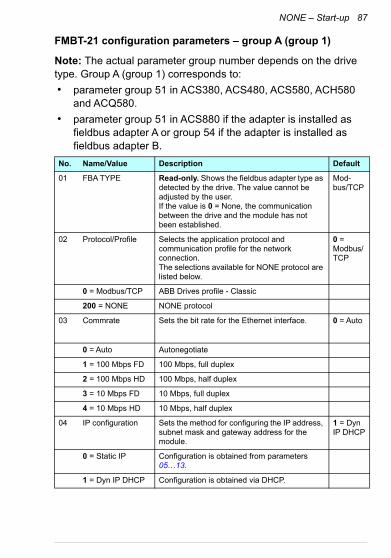
NONE – Start-up 87
FMBT-21 configuration parameters – group A (group 1)
Note: The actual parameter group number depends on the drive type. Group A (group 1) corresponds to:
• parameter group 51 in ACS380, ACS480, ACS580, ACH580 and ACQ580.
• parameter group 51 in ACS880 if the adapter is installed as fieldbus adapter A or group 54 if the adapter is installed as fieldbus adapter B.
No. Name/Value Description Default
01 FBA TYPE Read-only. Shows the fieldbus adapter type as detected by the drive. The value cannot be adjusted by the user. If the value is 0 = None, the communication between the drive and the module has not been established.
Mod-bus/TCP
02 Protocol/Profile Selects the application protocol and communication profile for the network connection.The selections available for NONE protocol are listed below.
0 = Modbus/TCP
0 = Modbus/TCP ABB Drives profile - Classic
200 = NONE NONE protocol
03 Commrate Sets the bit rate for the Ethernet interface. 0 = Auto
0 = Auto Autonegotiate
1 = 100 Mbps FD 100 Mbps, full duplex
2 = 100 Mbps HD 100 Mbps, half duplex
3 = 10 Mbps FD 10 Mbps, full duplex
4 = 10 Mbps HD 10 Mbps, half duplex
04 IP configuration Sets the method for configuring the IP address, subnet mask and gateway address for the module.
1 = Dyn IP DHCP
0 = Static IP Configuration is obtained from parameters 05…13.
1 = Dyn IP DHCP Configuration is obtained via DHCP.

88 NONE – Start-up
05 IP address 1 An IP address is assigned to each IP node on a network. An IP address is a 32-bit number that is typically represented in “dotted decimal” notation consisting of four decimal integers, on the range 0…255, separated by periods. Each integer represents the value of one octet (8-bits) in the IP address. Parameters 05...08 define the four octets of the IP address.
0
0…255 IP address
… … … …
08 IP address 4 See parameter 05 IP address 1. 0
0…255 IP address
No. Name/Value Description Default
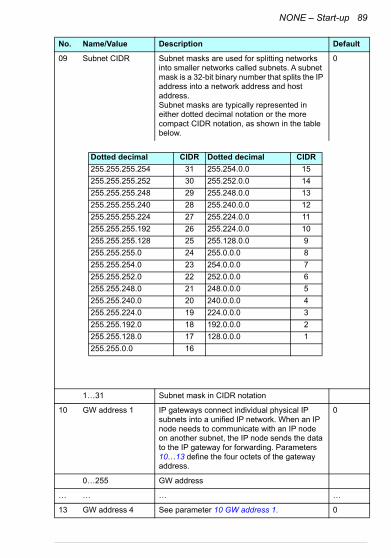
NONE – Start-up 89
09 Subnet CIDR Subnet masks are used for splitting networks into smaller networks called subnets. A subnet mask is a 32-bit binary number that splits the IP address into a network address and host address. Subnet masks are typically represented in either dotted decimal notation or the more compact CIDR notation, as shown in the table below.
0
1…31 Subnet mask in CIDR notation
10 GW address 1 IP gateways connect individual physical IP subnets into a unified IP network. When an IP node needs to communicate with an IP node on another subnet, the IP node sends the data to the IP gateway for forwarding. Parameters 10…13 define the four octets of the gateway address.
0
0…255 GW address
… … … …
13 GW address 4 See parameter 10 GW address 1. 0
No. Name/Value Description Default
Dotted decimal CIDR Dotted decimal CIDR
255.255.255.254 31 255.254.0.0 15
255.255.255.252 30 255.252.0.0 14
255.255.255.248 29 255.248.0.0 13
255.255.255.240 28 255.240.0.0 12
255.255.255.224 27 255.224.0.0 11
255.255.255.192 26 255.224.0.0 10
255.255.255.128 25 255.128.0.0 9
255.255.255.0 24 255.0.0.0 8
255.255.254.0 23 254.0.0.0 7
255.255.252.0 22 252.0.0.0 6
255.255.248.0 21 248.0.0.0 5
255.255.240.0 20 240.0.0.0 4
255.255.224.0 19 224.0.0.0 3
255.255.192.0 18 192.0.0.0 2
255.255.128.0 17 128.0.0.0 1
255.255.0.0 16

90 NONE – Start-up
0…255 GW address
14 Commrate port 2 Sets the bit rate for the Ethernet port 2. 0 = Auto
0 = Auto Autonegotiate
1 = 100 Mbps FD 100 Mbps, full duplex
2 = 100 Mbps HD 100 Mbps, half duplex
3 = 10 Mbps FD 10 Mbps, full duplex
4 = 10 Mbps HD 10 Mbps, half duplex
15 Service configuration
Disable services that are not required.Each service is represented by a single bit.Bit 0, Lock configuration, can be used to prevent accidental changing of thisparameter. By default, all services are enabled and configuration is unlocked.
0000b…1111b Service configuration
16…25
Reserved These parameters are not used by the adapter module when using the NONE protocol.
N/A
26 Reserved These parameters are not used by the adapter module when using the NONE protocol.
N/A
No. Name/Value Description Default
Bit Name Information
0 Lock configuration
Changing of this parameter are no longerpossible when this bit is set. Only reset fieldbus configuration to default will unlock the parameter.
1 Disable IP config tool
When this bit is set, access from ABB IPConfiguration tool is prevented.
2 Disable ETH tool network
When this bit is set, access from Ethernet tool network (eg, ABB Drive Composer tool) is prevented.
3 Disable ping response
When this bit is set, response to ICMP(ping) message is prevented.

NONE – Start-up 91
27 FBA A/B par refresh
Validates any changed adapter module configuration parameter settings. After refreshing, the value reverts automatically to 0 = Done.Note: This parameter cannot be changed while the drive is running.
0 = Done
0 = Done Refreshing done
1 = Refresh Refreshing
28 FBA A/B par table ver
Read-only. Displays the parameter table revision of the fieldbus adapter module mapping file stored in the memory of the drive.In format xyz, where x = major revision numbery = minor revision numberz = correction numberORin format axyz, where a = major revision numberxy = minor revision numbersz = correction number or letter.
N/A
Parameter table revision
29 FBA A/B drive type code
Read-only. Displays the drive type code of the fieldbus adapter module mapping file stored in the memory of the drive.
N/A
Drive type code of the fieldbus adapter module mapping file
30 FBA A/B mapping file ver
Read-only. Displays the fieldbus adapter module mapping file revision stored in the memory of the drive in decimal format.
N/A
Mapping file revision
31 D2FBA A/B comm status
Read-only. Displays the status of the fieldbus adapter module communication.Note: The value names may vary by drive.
0 = Idle or4 = Off-lineor2 = Time out
0 = Idle Adapter is not configured.
1 = Exec.init Adapter is initializing.
2 = Time out A timeout has occurred in the communication between the adapter and the drive.
No. Name/Value Description Default
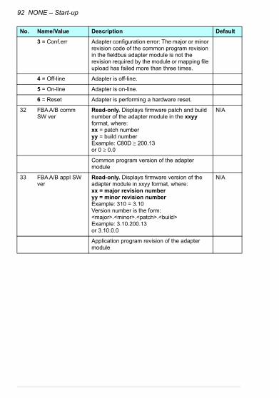
92 NONE – Start-up
3 = Conf.err Adapter configuration error: The major or minor revision code of the common program revision in the fieldbus adapter module is not the revision required by the module or mapping file upload has failed more than three times.
4 = Off-line Adapter is off-line.
5 = On-line Adapter is on-line.
6 = Reset Adapter is performing a hardware reset.
32 FBA A/B comm SW ver
Read-only. Displays firmware patch and build number of the adapter module in the xxyy format, where:xx = patch numberyy = build numberExample: C80D 200.13 or 0 0.0
N/A
Common program version of the adapter module
33 FBA A/B appl SW ver
Read-only. Displays firmware version of the adapter module in xxyy format, where:xx = major revision numberyy = minor revision numberExample: 310 = 3.10Version number is the form: <major>.<minor>.<patch>.<build>Example: 3.10.200.13or 3.10.0.0
N/A
Application program revision of the adapter module
No. Name/Value Description Default
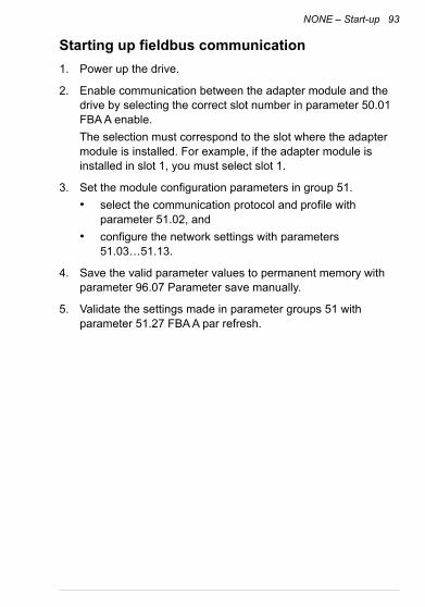
NONE – Start-up 93
Starting up fieldbus communication
1. Power up the drive.
2. Enable communication between the adapter module and the drive by selecting the correct slot number in parameter 50.01 FBA A enable.
The selection must correspond to the slot where the adapter module is installed. For example, if the adapter module is installed in slot 1, you must select slot 1.
3. Set the module configuration parameters in group 51.
• select the communication protocol and profile with parameter 51.02, and
• configure the network settings with parameters 51.03…51.13.
4. Save the valid parameter values to permanent memory with parameter 96.07 Parameter save manually.
5. Validate the settings made in parameter groups 51 with parameter 51.27 FBA A par refresh.

94 NONE – Start-up
NONE – Diagnostics 95
13NONE – Diagnostics
Contents of this chapter
This chapter explains how to trace faults with the status LEDs on the adapter module using the NONE protocol.
Fault and warning messages
For the fault and warning messages concerning the adapter module, see the drive firmware manual.

96 NONE – Diagnostics
LEDs
The adapter module is equipped with three bicolor diagnostic LEDs. The LEDs are described below.
Name Color Function
HOST
Blinking green Establishing communication to host
Green Connection to host OK
Blinking red Communication to host lost temporarily
Blinking orange, alternating with the MODULE blinking orange
Internal file system error. The error may be cleared by cycling drive power. If the error persists, contact your local ABB representative.
MODULE
Off There is no PC tool connected to the device.
Flashing orange Device is attempting to obtain IP configuration from the DHCP server.
Orange Device is executing Duplicate Address Detection.
Green PC tool is connected to the device.
Flashing red Ethernet link is down.
Red Ethernet interface is disabled. Duplicate Address Detection may have detected a duplicate address. Check the IP configuration and either initiate a Fieldbus Adapter parameter refresh or cycle power to the drive.
Flashing orange, alternating with the HOST flashing orange
Internal file system error. The error may be cleared by cycling drive power. If the error persists, contact your local ABB representative.
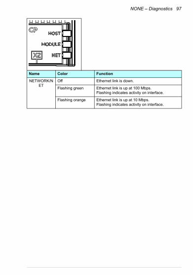
NONE – Diagnostics 97
NETWORK/NET
Off Ethernet link is down.
Flashing green Ethernet link is up at 100 Mbps.Flashing indicates activity on interface.
Flashing orange Ethernet link is up at 10 Mbps.Flashing indicates activity on interface.
Name Color Function

98 NONE – Diagnostics

Technical data 99
14Technical data
Contents of this chapter
This chapter contains the technical specifications of the adapter module and the Ethernet link.

100 Technical data
FMBT-21
The figure below shows the enclosure of the adapter module from the front and side.
Installation Into an option slot on the drive control unit
Degree of protection IP20
Ambient conditions The applicable ambient conditions specified for the drive in its manuals are in effect.
Package Cardboard. Plastic wrapping: Antistatic air bubble sheet (PE).
Indicators Three bicolor LEDs (HOST, MODULE, NETWORK/NET)
Connectors A 20-pin connector to the drive RJ-45 connector to Ethernet (X1)RJ-45 connector for chaining another adapter module (X2)
Power supply +3.3 V ±5% max. 400 mA (supplied by the drive)
General Complies with EMC standard EN 61800-3:2004Printed circuit board conformal coated

Technical data 101
Ethernet linkCompatible devices Ethernet Standard IEEE 802.3 and IEEE 802.3u devices
Medium 10BASE-TX or 100Base-TX with Auto-negotiation and Auto-MDIX (Auto-crossover)• Wiring: CAT5/6 UTP, CAT5/6 FTP, CAT5/6 STP• Connector: RJ-45• Termination: Internal• Maximum segment length: 100 m / 328 ft
Topology Bus or star.Max. 50 nodes allowed for FMBT-21 in a daisy chain topology.
Transfer rate 10 Mbps or 100 Mbps
Serial communication type
Half or full duplex
Protocol Modbus/TCP
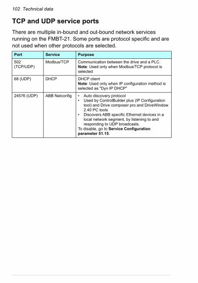
102 Technical data
TCP and UDP service ports
There are multiple in-bound and out-bound network services running on the FMBT-21. Some ports are protocol specific and are not used when other protocols are selected.
Port Service Purpose
502 (TCP/UDP)
Modbus/TCP Communication between the drive and a PLC. Note: Used only when Modbus/TCP protocol is selected
68 (UDP) DHCP DHCP clientNote: Used only when IP configuration method is selected as "Dyn IP DHCP"
24576 (UDP) ABB Netconfig • Auto discovery protocol• Used by ControlBuilder plus (IP Configuration
tool) and Drive composer pro and DriveWindow 2.40 PC tools
• Discovers ABB specific Ethernet devices in a local network segment, by listening to and responding to UDP broadcasts.
To disable, go to Service Configuration parameter 51.15.
Appendix A – ABB IP configuration tool for FMBT-21 103
15Appendix A – ABB IP configuration tool for FMBT-21
Contents of this chapter
This chapter shows how to use the ABB IP configuration tool to:
• find configured and unconfigured FMBT-21 adapter modules in the network
• rewrite the IP configuration of the adapter modules.
Installation
The ABB IP configuration tool is part of the Control Builder Plus software. No separate installation is needed.

104 Appendix A – ABB IP configuration tool for FMBT-21
Finding adapter modules in the network
1. Open the ABB IP configuration tool.
2. Click the Scan button.
The FMBT-21 adapter modules present in the network appear on the results list.

Appendix A – ABB IP configuration tool for FMBT-21 105
Rewriting the IP configuration of adapter modules
1. Scan the network for adapter modules.
For instructions, see section Finding adapter modules in the network on page 104.
2. On the results list, click to select the adapter module whose IP configuration you want to modify.
3. Below New configuration, define the IP configuration settings according to your network configuration.
4. If you want the adapter module to use a static IP address instead of DHCP, clear the DHCP check box.

106 Appendix A – ABB IP configuration tool for FMBT-21
5. To apply the new settings, click the Send Configuration button.
The new current IP address and configured IP address appear on the results list.

Further information
Product and service inquiriesAddress any inquiries about the product to your local ABB representative, quoting the type designation and serial number of the unit in question. A listing of ABB sales, support and service contacts can be found by navigating to www.abb.com/searchchannels.
Product trainingFor information on ABB product training, navigate to new.abb.com/service/training.
Providing feedback on ABB Drives manualsYour comments on our manuals are welcome. Navigate to new.abb.com/drives/manuals-feedback-form.
Document library on the InternetYou can find manuals and other product documents in PDF format on the Internet at www.abb.com/drives/documents.

Contact us
www.abb.com/drives www.abb.com/solar www.abb.com/windconverterswww.abb.com/drivespartners
3AXD50000158607 Rev A (EN) 2017-11-30