modbus tcp master/slave driver for deltav virtual i/o module · 2019-12-20 · modbus tcp...
TRANSCRIPT

Modbus TCP Master/Slave Driver for DeltaV Virtual I/O Module
ModbusTCP Firmware v3.9.3 or later For Simplex and Redundant Applications
USER MANUAL
February 2011

Disclaimers
©MYNAH Technologies 20069. All rights reserved.
Designs are marks of MYNAH Technologies; Emerson Process Management, DeltaV, and the DeltaV
design are marks of Emerson Process Management. All other marks are property of their respective
owners.
While this information is presented in good faith and believed to be accurate, Mynah Technologies does
not guarantee satisfactory results from reliance upon such information. Nothing contained herein is to be
construed as a warranty or guarantee, express or implied, regarding the performance, merchantability,
fitness or any other matter with respect to the products, nor as a recommendation to use any product or
process in conflict with any patent. Mynah Technologies reserves the right, without notice, to alter or
improve the designs or specifications of the products described herein. All sales are governed by Mynah
Technologies’ terms and conditions, which are available on request.

Table of Contents
1.0 Introduction .................................................................................................................................................... 2
1.1 Scope ............................................................................................................................................................ 2
1.2 Document Format ........................................................................................................................................ 2
1.3 System Specifications .................................................................................................................................. 3
2.0 Theory of Operation ....................................................................................................................................... 4
2.1 DeltaV Native I/O ........................................................................................................................................ 5
2.2 Modbus Devices ........................................................................................................................................... 6
2.3 Messaging Options ....................................................................................................................................... 6
2.4 Master/Slave Communications .................................................................................................................... 7
3.0 VIMNet Explorer ............................................................................................................................................ 8
3.1 Installation of Simplex Virtual I/O Module (VIM) Hardware ..................................................................... 8
3.2 Installation of Redundant Virtual I/O Module (VIM) Hardware ................................................................. 9
3.3 Installation of Software .............................................................................................................................. 10
3.4 Configuring Simplex VIM ......................................................................................................................... 13
3.5 Configuring Redundant VIM ..................................................................................................................... 19
3.6 Uploading a VIM Configuration ................................................................................................................ 31
3.7 Saving the VIM Configuration ................................................................................................................... 33
3.8 Flash Upgrade of the VIM ......................................................................................................................... 39
4.0 VIMNet Diagnostics ..................................................................................................................................... 42
4.1 VIM Level Diagnostics & Statistics ........................................................................................................... 43
4.2 Network Statistics ...................................................................................................................................... 45
4.3 Redundancy Statistics ................................................................................................................................ 47
4.4 Slave Statistics ........................................................................................................................................... 49
4.5 Port Level Diagnostics ............................................................................................................................... 50
4.6 Device Level Diagnostics .......................................................................................................................... 51
4.7 Dataset Level Diagnostics .......................................................................................................................... 52
4.8 Diagnostics Datasets .................................................................................................................................. 53
5.0 Configuring DeltaV ...................................................................................................................................... 55
5.1 Configure Datasets ..................................................................................................................................... 58
5.2 Configuring a 16-bit dataset for Input/Holding Registers .......................................................................... 66
5.3 Configuring a 16-bit dataset for Coils/Input Status bits ............................................................................. 68
5.4 Configuring a Floating Point or 32-bit dataset ........................................................................................... 71
5.5 Configuring a Boolean/Discrete dataset for Coils/Input Status data .......................................................... 73
5.6 Configuring a dataset for VIM Diagnostics ............................................................................................... 75
5.7 Customization ............................................................................................................................................ 78
5.8 Dataset Scan Control .................................................................................................................................... 82
5.9 Configuring Master/Slave Functionality .................................................................................................... 85
6.0 Redundant I/O Communications .............................................................................................................. 104
6.1 Redundancy Theory of Operations .......................................................................................................... 104
6.2 The Ping ................................................................................................................................................... 110
6.3 Simplex External Device .......................................................................................................................... 111
6.4 Redundant External Device - Single Chassis with 2 NICs ....................................................................... 112
6.5 Redundant External Device – 2 HSBY Chassis with 1 NIC Each ........................................................... 114
6.6 Redundant External Device – 2 HSBY Chassis with 2 NICs Each .......................................................... 116
6.7 User Application Initiated Redundant Switchover ................................................................................... 118
6.8 Hot Replacement of faulty Redundant VIM ............................................................................................ 119
7.0 Operational Check ...................................................................................................................................... 122
7.1 Scope ........................................................................................................................................................ 122
7.2 Verify Hardware and Software Version Number ..................................................................................... 122
7.3 Verify Configuring ................................................................................................................................... 122
7.4 Verify I/O Communication with Control Studio ...................................................................................... 122
7.5 Using DeltaV Diagnostics ........................................................................................................................ 122
7.6 LED Indication ......................................................................................................................................... 123
8.0 Technical Support ...................................................................................................................................... 125

9.0 Example Use Cases ..................................................................................................................................... 126
9.1 Schneider Quantum PLC HSBY – 2 NICs ............................................................................................... 126
9.2 Schneider Quantum PLC HSBY – 4 NICs ............................................................................................... 128
9.3 Invensys Triconex .................................................................................................................................... 129
9.4 Bently Nevada .......................................................................................................................................... 133
9.5 ControlLogix via ProSoft Card ................................................................................................................ 134
9.6 Emerson S600 Flow Computer ................................................................................................................ 135

Table of Figures and Tables
Table 1: Modbus TCP Driver System Specifications .................................................................................................... 3
Figure 1: Simplex Modbus TCP Network ..................................................................................................................... 4
Figure 2: Redundant Modbus TCP Network ................................................................................................................. 5
Figure 3: Simplex VIM Assembly ................................................................................................................................. 8
Figure 4: Redundant VIM Assembly ............................................................................................................................. 9
Table 2: VIMNet Diagnostics ...................................................................................................................................... 44
Table 3: VIMNet Diagnostics Dataset – Page 1 .......................................................................................................... 53
Table 3: VIMNet Diagnostics Dataset – Page 1 (continued) ....................................................................................... 54
Table 4: VIMNet Diagnostics Dataset – Page 2 .......................................................................................................... 54
Table 4: PLC Data Type Values and Registers ........................................................................................................... 60
Table 5: PLC Registers, Start Addresses, and Descriptions ........................................................................................ 60
Table 6: DeltaV and PLC Registers ............................................................................................................................. 60
Table 7a: Dataset Specification ................................................................................................................................... 61
Table 7b: Modbus Read Function Codes ..................................................................................................................... 61
Table 7c: Modbus Write Function Codes .................................................................................................................... 61
Table 8: Ping Customization ..................................................................................................................................... 110
Figure 5: Redundant VIMs with Simplex Modbus Devices ...................................................................................... 111
Figure 6: Redundant VIMs with Redundant PLC Network Connections .................................................................. 112
Table 9: Non-switching IP, VIM A Active ................................................................................................................ 113
Table 10: Non-switching IP, VIM B Active .............................................................................................................. 113
Figure 7: Redundant VIMs with PLC configured as Hot Backup, 2 NICs ................................................................ 114
Table 11: Switching IP, VIM A Active ..................................................................................................................... 115
Table 12: Switching IP, VIM B Active ..................................................................................................................... 115
Figure 8: Redundant VIMs with PLC configured as Hot Backup, 4 NICs ................................................................ 116
Figure 9: Redundant VIM Network ........................................................................................................................... 119
Table 13: Verifying Hardware and Software Version Numbers ................................................................................ 122
Table 14: LED Indication .......................................................................................................................................... 123
Table 15: Simplex VIM LED State Specifications .................................................................................................... 123
Table 16: Redundant VIM LED State Specifications ................................................................................................ 124

Modbus TCP User Manual
_____________________________________________________________________________________________________ 504 Trade Center Blvd. • Chesterfield, MO 63005 • Telephone (636) 681-1555 • Fax (636) 681-1660 • www.mynah.com
2
1.0 Introduction
1.1 Scope This document is the User Manual for the Virtual I/O Module (VIM) with the ModbusTCP master driver firmware for the Emerson Process Management (EPM) DeltaV Control System. It provides the information required to install, configure, and maintain the driver firmware on the VIM. The reader should be familiar with EPM’s DeltaV Programmable Serial Interface Cards (PSIC), Modbus protocol, and connected external devices (supporting the ModbusTCP protocol). The section Document Format briefly describes the contents of each section of this manual. System Specifications outlines hardware and software requirements for the ModbusTCP Driver firmware.
1.2 Document Format This document is organized as follows:
Introduction Describes the scope and purpose of this document.
Theory of Operation Provides a general functional overview of the Modbus TCP Driver.
Firmware Flash Upgrade Describes procedures to upgrade the Modbus TCP driver firmware in the VIM.
DeltaV serial card Configuration Describes procedures and guidelines for configuring the DeltaV serial cards residing in the VIM.
VIM network configuration Describes Modbus TCP network device configuration.
Operational Check Provides tips and assistance to ensure the VIM is properly setup and configured.
Technical Support Describes who to call if you need assistance.

Modbus TCP User Manual
_____________________________________________________________________________________________________ 504 Trade Center Blvd. • Chesterfield, MO 63005 • Telephone (636) 681-1555 • Fax (636) 681-1660 • www.mynah.com
3
1.3 System Specifications The following table lists the minimum system requirements for the Modbus TCP Driver:
Firmware Modbus TCP Driver Firmware, IOD-4101
VIMNet Utility Windows PC resident VIMNet Explorer Utility.
Protocol Compatibility ModbusTCP protocol conforming to “MODBUS Messaging on TCP/IP, Implementation Guide”, Rev 1.0, May 2002. This document is available from MODBUS.ORG
Software Requirements DeltaV System Software (Release 6.3 or later) installed on a hardware-appropriate Windows workstation configured as a ProfessionalPlus for DeltaV
Serial Interface Port License (VE4102).
For DeltaV 8.4 or earlier: One license is required for each serial port used. The VIM has a maximum of 8 available serial ports.
For DeltaV 9.3 or later: No serial port licenses are required. For DeltaV licenses, the VIM's datasets are counted based on DST usage.
MYNAH VIM driver firmware IOD-4101
Minimum DeltaV Hardware Requirements
DeltaV MD, MD Plus, MX and SX Controllers
1 standard 2 wide controller carrier
1 standard Power Supply
VIM Hardware Requirements MYNAH VIM part no. MIM-4207 or VIM-4201
For Simplex installation: 1 standard 2-wide controller carrier (Model Number VE3051C0) and 1 standard Power Supply (Model Number VE5008)
For Redundant installation: 2 standard 2-wide controller carrier (Model Number VE3051C0) and 2 standard Power Supply (Model Number VE5008). Use of VIM-4201 is recommended for redundant applications.
Network Hardware Requirements
Multiport 10/100BaseT Switch not shared with DeltaV Control Network. A single network switch or two network switches may be used for redundant communication.
Table 1: Modbus TCP Driver System Specifications

Modbus TCP User Manual
_____________________________________________________________________________________________________ 504 Trade Center Blvd. • Chesterfield, MO 63005 • Telephone (636) 681-1555 • Fax (636) 681-1660 • www.mynah.com
4
2.0 Theory of Operation The DeltaV Virtual I/O Module (VIM) provides a native DeltaV I/O interface to open plant Ethernet networks and devices that use ModbusTCP (RTU TCP, RTU via TCP and RTU via UDP) protocol. DeltaV controllers can read and write signals from the plant floor devices that use these Ethernet networks such as PLCs, Motor Control Centers, and Weigh Scales. As such, the VIM is a Network Gateway between DeltaV controllers and external devices supporting network communications. This connectivity is illustrated below:
Figure 1: Simplex Modbus TCP Network

Modbus TCP User Manual
_____________________________________________________________________________________________________ 504 Trade Center Blvd. • Chesterfield, MO 63005 • Telephone (636) 681-1555 • Fax (636) 681-1660 • www.mynah.com
5
Figure 2: Redundant Modbus TCP Network
2.1 DeltaV Native I/O The VIM provides a native DeltaV I/O interface by emulating four Programmable Serial Interface Cards (PSIC). By design, the VIM acquires the last 8-wide I/O carrier of a DeltaV system, emulating cards 57-60 or 61-64 as a single, simplex unit. Installing 2 simplex VIMs side-by-side provides emulation of all 8 serial I/O cards 57-64. The configuration of card group 57-60 or 61-64, and network properties of connected external devices is done in the VIMNet Explorer described in Section 3. For redundancy support, the appropriate firmware (v 3.6.0 or later) must be flashed into the VIM. Four redundant PSICs are emulated when 2 VIMs are installed side-by-side and configured as a redundant pair. One VIM emulates all odd numbered serial cards, while the other VIM emulates all even numbered serial cards. The emulated serial cards behave as redundant pairs, i.e., 57/58, 59/60, etc. However, when redundancy switchover occurs, all cards behave as a bank and switch in unison. For example, if there is a

Modbus TCP User Manual
_____________________________________________________________________________________________________ 504 Trade Center Blvd. • Chesterfield, MO 63005 • Telephone (636) 681-1555 • Fax (636) 681-1660 • www.mynah.com
6
communication error on card 57 that requires a switchover, the VIM will switch to its partner and cards 58, 60, 62 and 64 will become active. The emulated serial cards appear to DeltaV as real serial I/O. The configuration of data tables to be read and written is done at the DeltaV Explorer level, in the same manner as required for a serial PLC device. This allows communications with any PLC or non-PLC device that supports the Modbus TCP messaging. Each PSIC has 2 ports configured under it. There are 16 datasets under each port. Consequently, the VIM has the capacity of 128 datasets. One dataset is equivalent to 100 16-bit registers, or 50 floating point (32 bit) registers. These 128 datasets are user mapped to PLC devices as required for your application.
2.2 Modbus Devices The Modbus device address is considered unique in the serial cards port domain. Specifically, within a serial port, all configured Modbus devices are unique. You can, however, configure the same device with the same address under another port. For a device address configured more than once under more than one port, the IP address always remains unique. The VIMNet Explorer configuration correlates each unique Modbus address with an IP address. At the simplest level, each Modbus device equates to an IP address. In some cases, a single IP address may also be mapped to more than one Modbus device, as is typically required when interfacing with Motor Control Centers. In this case, the IP address mapped belongs to a bridge or gateway device, which in turn acts as a data concentrator communicating with multiple actual Modbus devices, each with a unique address. The bridge or gateway device typically communicates serially with its slaves. For example, Modbus Ethernet Bridges manufactured by Schneider Electric (part # 174CEV30020 or TSX ETG 100) are such devices. These are network devices that communicate via ModbusTCP with the VIM. The message packets are converted to standard Modbus and serially transmitted over RS-232 or RS-485 to slave devices. The subsequent responses are converted and transmitted to the VIM via ModbusTCP. Because of the serial communications (maximum baud rate of 19.2k), you can expect message times of 1-2 seconds. In Simplex mode, the VIM has the capacity to communicate with up to 32 network devices simultaneously. The communications tasks in the VIM are all active concurrently, each handling the messaging for the configured device (with its unique IP address). Of the 32 network devices, any mix of TCP and UDP devices can be configured. In Redundant mode, the VIM pair has the capacity to communicate with up to 16 network devices. In general each Modbus device is sent read/write requests for one dataset at a time. Depending on CPU load on the Modbus device the turn around can be as low as 10 msec. or as high as 200 msec. per dataset. To increase throughput some Modbus devices, e.g. Schnieider’s 140 NOE 77101 allow multiple connections, with each connection handling 16 messages simultaneously. The rules of Modicon CPU loading still apply, however, this mechanism allows for higher throughput. The VIM makes use of this by allowing you to configure the maximum messages per device. See section 3.4 for details.
2.3 Messaging Options

Modbus TCP User Manual
_____________________________________________________________________________________________________ 504 Trade Center Blvd. • Chesterfield, MO 63005 • Telephone (636) 681-1555 • Fax (636) 681-1660 • www.mynah.com
7
Devices configured in the VIM are configured to communicate using RTU TCP, RTU via TCP or RTU via UDP.
• RTU TCP comprises the Open ModbusTCP message structure. Message packets contain a 6-byte header as defined by the ModbusTCP standard. Messages are received and transmitted using TCP.
• RTU via TCP is simply Modbus messaging encapsulated and transmitted over the network using TCP. Messages are received and transmitted using TCP.
• RTU via UDP is similar to RTU via TCP. It is simply Modbus messaging transmitted over the network using UDP.
2.4 Master/Slave Communications
In Simplex mode, the VIM can simultaneously behave as a Master to external Modbus TCP slaves and as a Slave to external Modbus TCP masters. Slave functionality is not available in Redundant mode. In Redundant mode, the VIM can only behave as a Master. Master/Slave functionality is configured in DeltaV at the Serial cards port level. If a port is of Master type, then all underlying devices are considered to be external slaves to whom the VIM will actively connect as the master. If a port is of Slave type, then all underlying devices passively wait to be connected to by an external master. Because a simplex VIM can be both a Master and a Slave, it can be deployed in conjunction with other similarly configured VIMs for fast, VIM to VIM data exchange. The slave functionality is only available for RTU TCP type communications, i.e., communications using the Open Modbus TCP standard. Other communications using the RTU VIA TCP or RTU VIA UDP do not have slave support. The Slave device handler allows connections from 16 external Masters. Each open connection is handled by an independent task running in the VIM which maintains a 3 second timeout for received messages. If no request is received from the external Master in 3 seconds, the network connection is closed, and the connection task terminates. Other connection tasks continue to run, independently handling requests received from their respective Masters. In Master only mode, a Simplex VIM can communicate with a maximum of 32 external slave devices. By adding a slave port, the number of supported external slaves is reduced to 16. This allows 16 external Masters to connect to the VIM at the same time. Furthermore, in Master only mode, VIMs can be deployed as redundant pairs. For redundant VIMs, the maximum external slave’s is also 16.

Modbus TCP User Manual
_____________________________________________________________________________________________________ 504 Trade Center Blvd. • Chesterfield, MO 63005 • Telephone (636) 681-1555 • Fax (636) 681-1660 • www.mynah.com
8
3.0 VIMNet Explorer
3.1 Installation of Simplex Virtual I/O Module (VIM) Hardware Step 1 – You will need two 2-wide carriers, 2 power supplies, one DeltaV controller and one VIM. Mount a power supply on the left side and the DeltaV controller on the right side of one 2-wide carrier. The VIM can also be installed on the right side of the controller, but before any 8-wide is connected. Mount a power supply on the left side and the VIM on the right side of the second 2-wide carrier. Connect the second 2-wide carrier to the left edge of the Controller 2-wide carrier. Repeat this step for all simplex VIM installations. The final assembly should be as follows:
Figure 3: Simplex VIM Assembly
Step 2 – Connect a network cable from the VIM bottom port to a single isolated switch.
Note
Do not use the DeltaV Primary or Secondary switches for VIM external communications.
Step 3 – Connect the PC with the VIMNet software to isolated switch connected to the VIM. The DeltaV ProPlus PC may be used to host the VIMNet Explorer. However, a separate network card must be used for VIMNet communications.

Modbus TCP User Manual
_____________________________________________________________________________________________________ 504 Trade Center Blvd. • Chesterfield, MO 63005 • Telephone (636) 681-1555 • Fax (636) 681-1660 • www.mynah.com
9
3.2 Installation of Redundant Virtual I/O Module (VIM) Hardware Step 1 – You will need three 2-wide carriers, 3 power supplies, one DeltaV controller and two VIMs. Mount a power supply on the left side and the DeltaV controller on the right side of one 2-wide carrier. Mount a power supply on the left side and the VIM on the right side of the other two 2-wide carriers. Connect the two 2-wide VIM carriers together and to the left edge of the Controller 2-wide carrier. Repeat this step for all redundant VIM installations. The final assembly should be as follows:
Figure 4: Redundant VIM Assembly
Step 2 – Connect a network cable from each VIM Ethernet port to a separate dedicated isolated switch.
Note
Do not use the DeltaV Primary or Secondary switches for VIM external communications.
Step 3 – Connect the PC with the VIMNet software to either one of the isolated switches connected to the VIMs. The DeltaV ProPlus PC may be used to host the VIMNet Explorer. However, a separate network card must be used for VIMNet communications. Step 4 – Connect the two switches together with a straight network cable. This is required so that the VIMs can communicate with each other. Configuration and status information is passed between the VIMs using this connection. If this cable is not installed, VIMs will not be visible to each other and DeltaV Diagnostics will show a Standby unavailable error message. Step 5 – If the VIM-4201 VIM hardware is used, the redundancy link port must also be connected between the VIM’s. The redundancy link cable (supplied by Mynah) has RJ11 connectors on both ends. The VIM’s use this connection to send/receive redundancy data to each other. The cable pinout is as follows:

Modbus TCP User Manual
_____________________________________________________________________________________________________ 504 Trade Center Blvd. • Chesterfield, MO 63005 • Telephone (636) 681-1555 • Fax (636) 681-1660 • www.mynah.com
10
3.3 Installation of Software Software distribution is a single MSI file called VimNet.MSI as shown below. Double Click on VimNet.MSI to install VIMNet.
Step 1 – Launch the VIM Plug & Play Server by going to Start –> Programs –> VIMNet Explorer -> VIMNet Explorer.
Modbus TCP User Manual
_____________________________________________________________________________________________________ 504 Trade Center Blvd. • Chesterfield, MO 63005 • Telephone (636) 681-1555 • Fax (636) 681-1660 • www.mynah.com
11
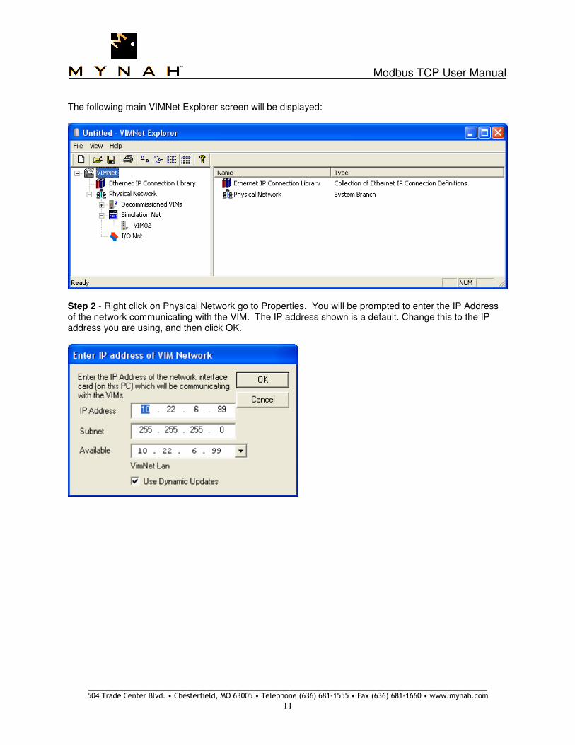
The following main VIMNet Explorer screen will be displayed:
Step 2 - Right click on Physical Network go to Properties. You will be prompted to enter the IP Address of the network communicating with the VIM. The IP address shown is a default. Change this to the IP address you are using, and then click OK.

Modbus TCP User Manual
_____________________________________________________________________________________________________ 504 Trade Center Blvd. • Chesterfield, MO 63005 • Telephone (636) 681-1555 • Fax (636) 681-1660 • www.mynah.com
12
Step 3 – Right click on I/O Net and select New Controller menu option. This will create a controller object underneath I/O Net. The controller will have a default name, e.g., Node1. Rename the created controller to match the controller name in DeltaV.

Modbus TCP User Manual
_____________________________________________________________________________________________________ 504 Trade Center Blvd. • Chesterfield, MO 63005 • Telephone (636) 681-1555 • Fax (636) 681-1660 • www.mynah.com
13
3.4 Configuring Simplex VIM Step 1 – Right click on the Controller to Add Virtual I/O Module (VIM) placeholder.
A dialog box will appear to Add Virtual IO Module:
Fill in the parameters as follows:
a. Name – Unique 32 character VIM name b. IP Address – an IP address in your network which is not currently being used c. Subnet Mask – remains as default d. Gateway – Specify the IP address of the network router so the VIM can access devices on
another network. Configure as 0.0.0.0 if a Gateway is not used.

Modbus TCP User Manual
_____________________________________________________________________________________________________ 504 Trade Center Blvd. • Chesterfield, MO 63005 • Telephone (636) 681-1555 • Fax (636) 681-1660 • www.mynah.com
14
e. Virtual Cards – select card group to be emulated by VIM, i.e., cards 57-60, or 61-64 f. Type – This is the VIM firmware type. Select Modbus TCP. g. Redundancy – Leave the “VIM is Redundant” checkbox unchecked. h. DeltaV version 10.x – click this checkbox if the DeltaV system is v10.3 or earlier, or v11.3
with M-Series I/O. For v11.3 with S-Series I/O, this field is unchecked. Note that if the Gateway field is disabled; enable it via the Windows Registry. The key is EnableDefaultGateway, DWORD, with a value of 1. The key path is My Computer\HKEY_CURRENT_USER\Software\Mynah Technologies\PPV\Settings After filling out the parameters, select OK. The Virtual I/O placeholder module has been added (note that the Virtual Cards appear and you are ready to commission.
Step 2 – Click on Decommissioned VIMs to display all available decommissioned VIMs. This list is dynamically populated as VIMs are detected on the network. Click the Decommissioned VIMs object in the left pane and verify the VIMs appear in the list in the right pane.

Modbus TCP User Manual
_____________________________________________________________________________________________________ 504 Trade Center Blvd. • Chesterfield, MO 63005 • Telephone (636) 681-1555 • Fax (636) 681-1660 • www.mynah.com
15
Step 3 – Right click on the VIM placeholder under I/O Net and select the Commission menu option.
a. Select the VIM to be commissioned from the List of Decommissioned VIMs. This will enable the OK button.
b. Click the Ping button to ensure the IP address to be assigned is not already used. The result is shown as Address Available or unavailable.
c. Select “Start Flashing” to identify the VIM you are commissioning. Once the correct VIM has been located, select Stop Flashing and then select OK.

Modbus TCP User Manual
_____________________________________________________________________________________________________ 504 Trade Center Blvd. • Chesterfield, MO 63005 • Telephone (636) 681-1555 • Fax (636) 681-1660 • www.mynah.com
16
When commissioned, the Active LED will stay steady green and your state on the VIMNet Explorer will indicate that the VIM is Commissioned - Good. The Standby LED will remain off.
Step 4 – Repeat Steps 1, 2 and 3 for all VIMs.
Step 5 - To complete VIM configuration, network devices must be added to the virtual cards. Right click on the Serial Port and select Add Device.

Modbus TCP User Manual
_____________________________________________________________________________________________________ 504 Trade Center Blvd. • Chesterfield, MO 63005 • Telephone (636) 681-1555 • Fax (636) 681-1660 • www.mynah.com
17
Fill in the Device parameters as follows:
a. Device Address – 1-254. This is the PLC address of the device, which must be the same as the device address configured in the DeltaV Explorer for the device. Device address 255 is reserved.
b. Description – up to 32 characters c. Click Add to add a new IP address and specify its properties. The following dialog will appear.
Note that unused IP addresses are automatically discarded from the list. All configured and available IP addresses are shown in the list. You can map a device to any available IP address. Furthermore, more than one device can be mapped to a single IP address.
Fill in the Device Communications parameters as follows:
a. Specify the IP address of the Modbus TCP PLC device. b. Select the communication protocol to be used with the Device. c. Enter 502 for the standard Modbus TCP Port Number. This can be modified as needed for the
external device. d. Adjust the Number of Simultaneous Messages (read requests) as needed. For example,
Quantum PLCs allow a maximum of 16 requests. Write requests are always one at a time. e. Check the Gateway Device checkbox if this device is a Bridge which supports multiple
simultaneous connections. For example, the Schneider Modbus Plus to Ethernet Bridge, part

Modbus TCP User Manual
_____________________________________________________________________________________________________ 504 Trade Center Blvd. • Chesterfield, MO 63005 • Telephone (636) 681-1555 • Fax (636) 681-1660 • www.mynah.com
18
number 174 CEV 200 40, is one such gateway. Similarly, the Schneider Modbus TCP to Serial Bridge, part number TSX ETG 100, is also a gateway. When checked, the Max Sessions field will become enabled. Specify the maximum number of simultaneous sessions the VIM should open when connecting with the gateway. Messages on each session are handled independently.
Click OK after filling the parameters. The following window shows multiple non-gateway devices configured.
Note
The mapping of device address to IP address is the most critical part of the VIM configuration. Care must be exercised to ensure correctness.
When you are finished configuring VIMs, continue to Section 3.6. To configure Redundant VIMs, continue to Section 3.5.
Modbus TCP User Manual
_____________________________________________________________________________________________________ 504 Trade Center Blvd. • Chesterfield, MO 63005 • Telephone (636) 681-1555 • Fax (636) 681-1660 • www.mynah.com
19
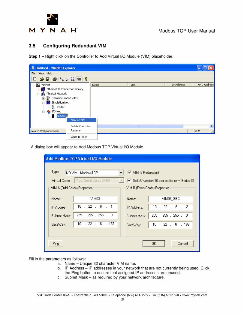
3.5 Configuring Redundant VIM Step 1 – Right click on the Controller to Add Virtual I/O Module (VIM) placeholder.
A dialog box will appear to Add Modbus TCP Virtual I/O Module
Fill in the parameters as follows:
a. Name – Unique 32 character VIM name. b. IP Address – IP addresses in your network that are not currently being used. Click
the Ping button to ensure that assigned IP addresses are unused. c. Subnet Mask – as required by your network architecture.

Modbus TCP User Manual
_____________________________________________________________________________________________________ 504 Trade Center Blvd. • Chesterfield, MO 63005 • Telephone (636) 681-1555 • Fax (636) 681-1660 • www.mynah.com
20
d. Gateway – Specify the IP address of the network routers so the VIMs can access devices on another network. Configure as 0.0.0.0 if a Gateway is not used.
e. Select the “VIM is Redundant” checkbox. f. Virtual Cards – All eight serial cards will be allocated as four redundant pairs. g. Type – This is the VIM firmware type. Select Modbus TCP. h. Check the VIM is Redundant checkbox. i. DeltaV version 10.x – click this checkbox if the DeltaV system is v10.3 or earlier, or
v11.3 with M-Series I/O. For v11.3 with S-Series I/O, this field is unchecked. Note that if the Gateway field is disabled; enable it via the Windows Registry. The key is EnableDefaultGateway, DWORD, with a value of 1. The key path is My Computer\HKEY_CURRENT_USER\Software\Mynah Technologies\PPV\Settings
After filling out the parameters, select OK. The Virtual I/O placeholder module has been added. (Note that the Virtual Cards appear and you are ready to commission.)
Step 2 – Click on Decommissioned VIMs to display all available decommissioned VIMs. This list is dynamically populated as VIMs are detected on the network. Click the Decommissioned VIMs object in the left pane and verify the VIMs appear in the list in the right pane.

Modbus TCP User Manual
_____________________________________________________________________________________________________ 504 Trade Center Blvd. • Chesterfield, MO 63005 • Telephone (636) 681-1555 • Fax (636) 681-1660 • www.mynah.com
21
Step 3 – Right click on the VIM placeholder under I/O Net and select the Commission menu option. You must commission both VIMs separately as VIM A and VIM B.
Select the VIM to be commissioned from the list of Decommissioned VIMs.
Select the Start Flashing Radio Button to identify the VIM you are commissioning. Once the correct VIM has been located, select Stop Flashing and then select OK. If the VIM cannot be located, check the network connection and power supply. Cancel the dialog and repeat Step 3.
When commissioned, the Active LED will stay steady green for VIM A and your state on the VIMNet Explorer will indicate commission good. VIM B will indicate that it is commissioned by changing the Standby LED to steady green and it will turn off the Active LED. The Active and Standby LEDs state on both VIMs will change based on redundancy role. Only one LED will be active on a VIM at a time, i.e., the Active and Standby LED cannot both be lit at the same time on one VIM.

Modbus TCP User Manual
_____________________________________________________________________________________________________ 504 Trade Center Blvd. • Chesterfield, MO 63005 • Telephone (636) 681-1555 • Fax (636) 681-1660 • www.mynah.com
22
Step 4 – Repeat Step 3 for the partner VIM.
Step 5 - To complete VIM configuration, Network devices must be added to the Virtual Cards. Right Click on the Serial Port and select the Add Device menu option. Adding a Non-Gateway Device Right click on the port and select Add Device as follows:
Fill in the parameters as follows:
a. Device Address – 1-254. This is the PLC address of the device, which must be the same as the device address configured in the DeltaV explorer for the serial card. Address 255 is reserved.
b. Description – up to 32 characters c. Click Add to add a new IP address and specify its properties. The following dialog will
appear. Note that unused IP addresses are automatically discarded from the list. All configured and available IP addresses are shown in the list. You can map a device to any

Modbus TCP User Manual
_____________________________________________________________________________________________________ 504 Trade Center Blvd. • Chesterfield, MO 63005 • Telephone (636) 681-1555 • Fax (636) 681-1660 • www.mynah.com
23
available IP address. Furthermore, more than one device can be mapped to a single IP address.
In this dialog: a. Specify the IP address of the Modbus TCP PLC device. b. If redundant, select the type of device redundancy being used. Device redundancy is described in
Section 7. c. Enter 502 for the standard Modbus TCP Port Number. This can be modified as needed for the
external device. d. Adjust the Number of Simultaneous Messages (read requests) as needed. For example,
Quantum PLCs allow a maximum of 16 requests. Write requests are always one at a time. e. The Gateway Device checkbox should remain unchecked.
Click OK after filling the parameters. The following window shows one non-gateway redundant device configured.

Modbus TCP User Manual
_____________________________________________________________________________________________________ 504 Trade Center Blvd. • Chesterfield, MO 63005 • Telephone (636) 681-1555 • Fax (636) 681-1660 • www.mynah.com
24
Adding a Gateway Device A Gateway device is one which supports multiple simultaneous network connections. Each connection opens a path to one of the underlying sub-devices as illustrated below with Modbus Plus Gateway.
Right click on the port and select Add Device as follows:

Modbus TCP User Manual
_____________________________________________________________________________________________________ 504 Trade Center Blvd. • Chesterfield, MO 63005 • Telephone (636) 681-1555 • Fax (636) 681-1660 • www.mynah.com
25
Fill in the parameters as follows:
a. Device Address – 1-254. This is the PLC address of the device, which must be the same as the device address configured in the DeltaV explorer for the serial card. Address 255 is reserved.
b. Description – up to 32 characters c. Click Add to add a new IP address and specify its properties. The following dialog will
appear. Note that unused IP addresses are automatically discarded from the list. All configured and available IP addresses are shown in the list. You can map a device to any available IP address. Furthermore, more than one device can be mapped to a single IP address.

Modbus TCP User Manual
_____________________________________________________________________________________________________ 504 Trade Center Blvd. • Chesterfield, MO 63005 • Telephone (636) 681-1555 • Fax (636) 681-1660 • www.mynah.com
26
In this dialog:
a. Specify the IP address of the Modbus TCP PLC device. b. Select the type of device redundancy being used. Device redundancy is described in Section
7. In this case, two Modbus Plus Gateways would be required. c. Enter 502 for the standard Modbus TCP Port Number. This can be modified as needed for
the external device. d. Adjust the Number of Simultaneous Messages (read requests) as needed. For example,
Quantum PLCs allow a maximum of 16 requests. Write requests are always one at a time. e. Check the Gateway Device checkbox. The device being configured must be a Gateway
which supports multiple simultaneous connections. For example, the Schneider Modbus Plus to Ethernet Bridge, part number 174 CEV 200 40, is one such gateway shown in above illustration. Similarly, the Schneider Modbus TCP to serial converter, part number TSX ETG 100, is also a gateway. When checked, the Max Sessions field will become enabled. Specify the maximum number of simultaneous sessions the VIM should open when connecting with the gateway. Messages on each session are handled independently. In this example, we have selected 4 simultaneous sessions.
Click OK after filling the parameters. Repeat the above steps to add additional devices, selecting the existing IP address pair, and the same or different session number. The following window shows one gateway redundant device configured. This device exists in 4 sessions. Based on this, the VIM will open 4 independent, simultaneous connections to the device. Note that each device uses the same IP address pair.

Modbus TCP User Manual
_____________________________________________________________________________________________________ 504 Trade Center Blvd. • Chesterfield, MO 63005 • Telephone (636) 681-1555 • Fax (636) 681-1660 • www.mynah.com
27

Modbus TCP User Manual
_____________________________________________________________________________________________________ 504 Trade Center Blvd. • Chesterfield, MO 63005 • Telephone (636) 681-1555 • Fax (636) 681-1660 • www.mynah.com
28
Adding a Bridge Device A Bridge device is different from a Gateway device in that it only supports one network session. The underlying devices are usually connected to the Bridge via RS485 in a multi-drop architecture as shown below. The open connection multiplexes between the connected sub-devices. However this architecture delivers limited throughput. Loss of one sub-device can severely disrupt communications with the remaining sub-devices. Such architectures are not recommended, unless one bridge/one device is used.
Right click on the port and select Add Device as follows:
Modbus TCP User Manual
_____________________________________________________________________________________________________ 504 Trade Center Blvd. • Chesterfield, MO 63005 • Telephone (636) 681-1555 • Fax (636) 681-1660 • www.mynah.com
29
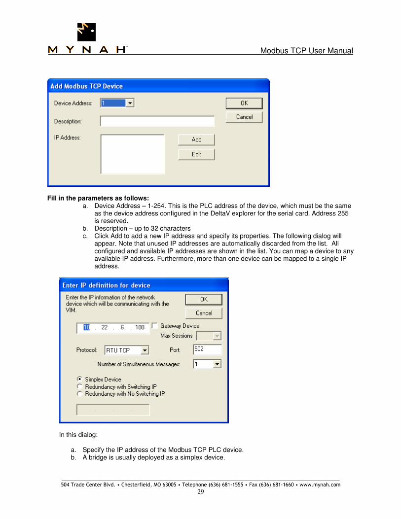
Fill in the parameters as follows:
a. Device Address – 1-254. This is the PLC address of the device, which must be the same as the device address configured in the DeltaV explorer for the serial card. Address 255 is reserved.
b. Description – up to 32 characters c. Click Add to add a new IP address and specify its properties. The following dialog will
appear. Note that unused IP addresses are automatically discarded from the list. All configured and available IP addresses are shown in the list. You can map a device to any available IP address. Furthermore, more than one device can be mapped to a single IP address.
In this dialog:
a. Specify the IP address of the Modbus TCP PLC device. b. A bridge is usually deployed as a simplex device.

Modbus TCP User Manual
_____________________________________________________________________________________________________ 504 Trade Center Blvd. • Chesterfield, MO 63005 • Telephone (636) 681-1555 • Fax (636) 681-1660 • www.mynah.com
30
c. Enter 502 for the standard Modbus TCP Port Number. This can be modified as needed for the external device.
d. Simultaneous Messages (read requests) must be set to 1. e. Leave the Gateway Device checkbox unchecked.
Click OK after filling the parameters. Repeat the above steps to add additional devices, specifying the same existing IP address. The following window shows one bridge device configured. This bridge has 3 underlying sub-devices, all sharing the same IP address but the device address is different. See Section 5.7 for additional dataset level flags required for bridged device communications.

Modbus TCP User Manual
_____________________________________________________________________________________________________ 504 Trade Center Blvd. • Chesterfield, MO 63005 • Telephone (636) 681-1555 • Fax (636) 681-1660 • www.mynah.com
31
3.6 Uploading a VIM Configuration
VIMNet configuration creates a mapping between PLC device addresses and IP addresses. This mapping must be uploaded into the VIM for proper communications. A configuration that has not been uploaded to the VIM is indicated with a blue triangle next to the VIM icon. To upload a configuration, the VIM must first be commissioned.
Uploading a new configuration into the VIM will cause all external communications to terminate. After upload completion, the VIM will automatically reboot and reconnect to the external devices. VIM upload must be done with the process in safe mode.
Right click on the VIM and select VIM Configuration Upload.
For simplex VIMs, the upload is direct. For redundant VIMs, the upload can be one VIM at a time, or both VIMs together. Note that if the VIMs are online, then uploading one at a time is recommended. Only the uploaded VIM will lose connections with the field. In this case, the Standby VIM should be uploaded first. Then from DeltaV Diagnostics, a VIM switchover should be executed, followed by an upload to the new Standby VIM. The upload procedure is as follows. When selected, the following warning is displayed:
Click Yes to continue. The uploading VIM Configuration progress bar will indicate the status of the upload:

Modbus TCP User Manual
_____________________________________________________________________________________________________ 504 Trade Center Blvd. • Chesterfield, MO 63005 • Telephone (636) 681-1555 • Fax (636) 681-1660 • www.mynah.com
32
Upon successful completion of the VIM Configuration Upload, click OK.
The upload process terminates all communications with DeltaV over the railbus. Upon upload completion, the VIM automatically reboots and goes online. Click OK to terminate the dialog. If your upload is unsuccessful, try again. Contact MYNAH Support if you are not successful in uploading.

Modbus TCP User Manual
_____________________________________________________________________________________________________ 504 Trade Center Blvd. • Chesterfield, MO 63005 • Telephone (636) 681-1555 • Fax (636) 681-1660 • www.mynah.com
33
3.7 Saving the VIM Configuration
VIMNet configuration is saved in a file with a .VIO extension. This file can be located anywhere in the PC local or network folder. The current state of commissioned VIMs, as well as VIM network device configurations is contained in this file.
Note
The VIO configuration file is very important, and must be saved in a safe location for future access to the VIM network for modification and troubleshooting. Failure to do so results in unnecessary loss of network information, which must then be recreated.
The VIMNet Explorer does not have to be online all the time. However, if it is restarted, this file should be reopened so that the current state of VIMs does not show as error. When the VIMNet Explorer is restarted, it will start scanning for VIMs on the network, and display what is found. Commissioned VIMs found on the network will be compared with configured placeholders and there current state displayed. Mismatched VIMs, i.e., those which do not exist as placeholders, or mismatches in MAC address or IP address will be displayed in the Decommissioned list as errors. The following shows VIMs in error.
If the original configuration file is not available, the VIMs in error must be manually cleared. The options are to either Reset the VIM in the Decommissioned list, Reconcile or Recover the contained configuration as described below.

Modbus TCP User Manual
_____________________________________________________________________________________________________ 504 Trade Center Blvd. • Chesterfield, MO 63005 • Telephone (636) 681-1555 • Fax (636) 681-1660 • www.mynah.com
34
Reset VIM To Reset a VIM, right click on the VIM in the Decommissioned list to get the context menu. Then select Reset as shown below. The VIMNet Explorer will send a Decommission command over the network, and clear the VIM from its list. It is anticipated that the Decommission command will be accepted by the VIM resulting in a decommissioned VIM. The VIM will then appear as an unconfigured, decommissioned VIM in the VIMNet Explorer list.
Performing a Reset will decommission a VIM. This will terminate all external communications.

Modbus TCP User Manual
_____________________________________________________________________________________________________ 504 Trade Center Blvd. • Chesterfield, MO 63005 • Telephone (636) 681-1555 • Fax (636) 681-1660 • www.mynah.com
35
Recover Configuration The configuration contained in a VIM can be read back and saved in the VIMNet Explorer.To Recover Configuration, right click on the VIM in the Decommissioned list to get the context menu. Then select Recover Configuration as shown below. In this example, we have a redundant pair of VIMs. The simplex VIM process is identical.
The progress bar will show configuration read back progress.
Once the configuration has been retrieved, the following dialog will prompt for the controller name where it will be saved.
Click New to get a new name or select a name from the list, then click OK. In the following prompt, select Yes.

Modbus TCP User Manual
_____________________________________________________________________________________________________ 504 Trade Center Blvd. • Chesterfield, MO 63005 • Telephone (636) 681-1555 • Fax (636) 681-1660 • www.mynah.com
36
The configuration retrieved will be saved under Node1 and VIM01 as Odd cards. Repeat the same process for the partner card. In the following dialog, select OK.
The following dialog will be displayed. Click Yes.
This completes the configuration recovery process.

Modbus TCP User Manual
_____________________________________________________________________________________________________ 504 Trade Center Blvd. • Chesterfield, MO 63005 • Telephone (636) 681-1555 • Fax (636) 681-1660 • www.mynah.com
37
Reconcile VIM The process of reconciling a detected, commissioned VIM, with an unassigned placeholder allows you to reconstruct a configuration file without decommissioning and then recommissioning the VIM. Detected VIMs are displayed in the Decommissioned VIMs list with a status of Commissioned – Unknown. To Reconcile a VIM, first create a new placeholder with the same IP address as the VIMs in the decommissioned list. Next, right click on the VIM in the I/O Net to get the context menu, then select Reconcile VIM menu option as shown below.
This will launch a dialog as follows, showing all the detected, commissioned, and unattached VIMS.
Select a VIM in the list and click OK. If the VIM placeholder is redundant and both VIMs are unattached, a dialog will be displayed as follows where you can select VIM A or VIM B.

Modbus TCP User Manual
_____________________________________________________________________________________________________ 504 Trade Center Blvd. • Chesterfield, MO 63005 • Telephone (636) 681-1555 • Fax (636) 681-1660 • www.mynah.com
38
If the VIM placeholder is simplex or if only one VIM out of a redundant pair is unattached, the reconcile process with immediately create the link without further prompts. The reconciled VIM will appear as normal and commissioned, and the decommissioned list will be cleared. Note that if you are creating a new configuration file, you must recreate the external device network definitions and then upload to the VIM.

Modbus TCP User Manual
_____________________________________________________________________________________________________ 504 Trade Center Blvd. • Chesterfield, MO 63005 • Telephone (636) 681-1555 • Fax (636) 681-1660 • www.mynah.com
39
3.8 Flash Upgrade of the VIM
For VIM functionality changes, MYNAH Technologies will issue firmware upgrade files as required. The new firmware files must be flashed into the VIM. If your current operating firmware version is v3.5.7 or earlier, please contact Mynah technical support for instructions on how to upgrade to the latest system.
Flashing a Simplex VIM with new firmware will cause all external communications to terminate. Upon flash completion, the VIM will automatically reboot. Flashing a Redundant VIM pair must begin with the standby unit. Upon flash completion, the VIM will automatically reboot and go back to standby state. Use DeltaV Diagnostics to initiate a switchover such that the standby unit becomes active. Next flash the new standby unit. VIM flash must be done with the process in safe mode.
To do this, right click on the target VIM object and select Properties. The following dialog box will appear:

Modbus TCP User Manual
_____________________________________________________________________________________________________ 504 Trade Center Blvd. • Chesterfield, MO 63005 • Telephone (636) 681-1555 • Fax (636) 681-1660 • www.mynah.com
40
Click Flash Upgrade. A warning will appear as follows:
Click Yes to start the flash process. Note that while flashing the VIM, all communications with DeltaV Controller are terminated. Browse to select the firmware file. Firmware files have a .HEX extension. Please contact Mynah Technical Support for the correct file to use.

Modbus TCP User Manual
_____________________________________________________________________________________________________ 504 Trade Center Blvd. • Chesterfield, MO 63005 • Telephone (636) 681-1555 • Fax (636) 681-1660 • www.mynah.com
41
Using an incorrect firmware file may render the VIM inoperable.
Select the file to continue the flash upgrade process. Note that the file format for the VIM should be: vim-modbustcp-vmajor version.minor version.maintenance build.full.hex. For example, see the file name in above dialog. Once the file has been selected, a connection is opened to the VIM and the flash system is downloaded. During the download, a progress bar will display as follows:
Upon completion, the VIM will reboot and go online. In case of redundant VIMs, both must be flashed separately to the same firmware revision.
Modbus TCP User Manual
_____________________________________________________________________________________________________ 504 Trade Center Blvd. • Chesterfield, MO 63005 • Telephone (636) 681-1555 • Fax (636) 681-1660 • www.mynah.com
42
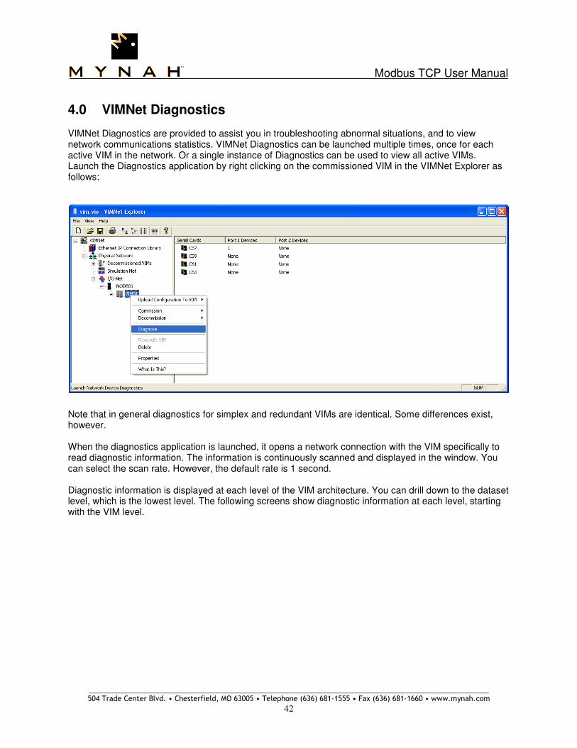
4.0 VIMNet Diagnostics VIMNet Diagnostics are provided to assist you in troubleshooting abnormal situations, and to view network communications statistics. VIMNet Diagnostics can be launched multiple times, once for each active VIM in the network. Or a single instance of Diagnostics can be used to view all active VIMs. Launch the Diagnostics application by right clicking on the commissioned VIM in the VIMNet Explorer as follows:
Note that in general diagnostics for simplex and redundant VIMs are identical. Some differences exist, however. When the diagnostics application is launched, it opens a network connection with the VIM specifically to read diagnostic information. The information is continuously scanned and displayed in the window. You can select the scan rate. However, the default rate is 1 second. Diagnostic information is displayed at each level of the VIM architecture. You can drill down to the dataset level, which is the lowest level. The following screens show diagnostic information at each level, starting with the VIM level.

Modbus TCP User Manual
_____________________________________________________________________________________________________ 504 Trade Center Blvd. • Chesterfield, MO 63005 • Telephone (636) 681-1555 • Fax (636) 681-1660 • www.mynah.com
43
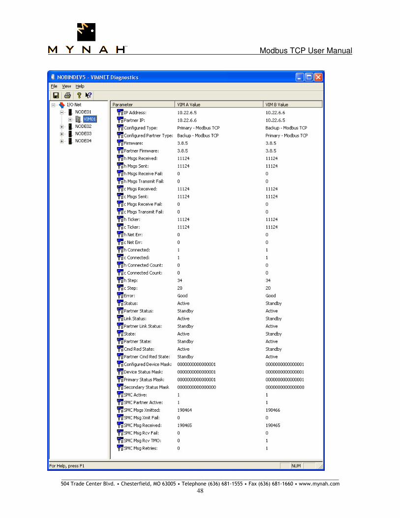
4.1 VIM Level Diagnostics & Statistics The first screen after launch is as follows if the VIM is redundant. If the VIM is simplex, the VIM B column is not displayed:

Modbus TCP User Manual
_____________________________________________________________________________________________________ 504 Trade Center Blvd. • Chesterfield, MO 63005 • Telephone (636) 681-1555 • Fax (636) 681-1660 • www.mynah.com
44
The information displayed in this window is explained in Table 2 below. Users can configure diagnostics datasets in DeltaV to read this information into the controller. This is discussed further in Section 4.8. Diagnostic Item Description VIM Mode Shows current mode: Commissioned, Failsafe, etc.0 – Normal Online, 1 – FailSafe
Data Poll Queue Number of messages waiting to be sent to DeltaV
Pending Message Queue Number of waiting diagnostics message responses to be sent to DeltaV
Railbus Message Queue Number of waiting Railbus messages received from DeltaV to be processed
Serial Bus Poll Counter of poll requests received from Controller
Dataset Value Reads Counter of dataset value read requests received from Controller Dataset Value Writes Counter of dataset value write requests received from Controller
Default Reads Counter of default read requests received from Controller
Pending Data Reads Counter of DeltaV Diagnostics data read requests received from Controller
Pending Data Writes Counter of DeltaV Diagnostics data write requests received from Controller
Railbus Ticker Ticker of process handling Railbus messages
Plug and Play Ticker Ticker of process handling Plug/Play messages Dataset Handler Ticker Ticker of process handling dataset updates
IP Address IP address of VIM
DeltaV Devices Number of DeltaV devices in configuration received from Controller
Network Devices Number of actual network devices configured/found
Application Application type: Modbus TCP
Flash I/O Step Reserved for Flash evaluation Flash I/O Connected Reserved for Flash evaluation
Flash I/O Error Reserved for Flash evaluation
Logging to IP address of PC if message logging is turned on
Total # DS Total number of datasets in this configuration
Maximum DS Scan (ms) Maximum scan time (ms) for single dataset based on 16 simultaneous messages Minimum DS Scan (ms) Minimum scan time (ms) for single dataset based on 16 simultaneous messages
Average DS Scan (ms) Average scan time (ms) for single dataset based on 16 simultaneous messages
Maximum Scan (ms) Maximum scan time (ms) for all datasets
Minimum Scan (ms) Minimum scan time (ms) for all datasets
Average Scan (ms) Average scan time (ms) for all datasets
Maximum Msgs(/s) Maximum messages per second Minimum Msgs (/s) Minimum messages per second
Average Msgs (/s) Average messages per second
Generation Rate (/s) Rate of DS changes detected in field data
Poll Rate (/s) Rate of DS Polls received from DeltaV controller
Number of buffers Total number of available buffers for Railbus message handling (max 255)
% Available Buffers Percent of available buffers Buffer Resets Count of buffer resets (internal VIM memory management)
Table 2: VIMNet Diagnostics

Modbus TCP User Manual
_____________________________________________________________________________________________________ 504 Trade Center Blvd. • Chesterfield, MO 63005 • Telephone (636) 681-1555 • Fax (636) 681-1660 • www.mynah.com
45
You can right click on the VIM to get a context menu. From this menu, you can clear all statistics by selecting Reset All Statistics.
4.2 Network Statistics
Right click on the VIM to get a context menu. From this menu, low level Ethernet Network Statistics can be displayed for simplex or redundant VIMs. The screenshot below shows statistics for VIM A in a redundant pair.

Modbus TCP User Manual
_____________________________________________________________________________________________________ 504 Trade Center Blvd. • Chesterfield, MO 63005 • Telephone (636) 681-1555 • Fax (636) 681-1660 • www.mynah.com
46

Modbus TCP User Manual
_____________________________________________________________________________________________________ 504 Trade Center Blvd. • Chesterfield, MO 63005 • Telephone (636) 681-1555 • Fax (636) 681-1660 • www.mynah.com
47
4.3 Redundancy Statistics
Right click on the VIM to get a context menu. From this menu, Redundancy Statistics can be displayed.
The screenshot below shows statistics for Active VIM A in a redundant pair.
Modbus TCP User Manual
_____________________________________________________________________________________________________ 504 Trade Center Blvd. • Chesterfield, MO 63005 • Telephone (636) 681-1555 • Fax (636) 681-1660 • www.mynah.com
48

Modbus TCP User Manual
_____________________________________________________________________________________________________ 504 Trade Center Blvd. • Chesterfield, MO 63005 • Telephone (636) 681-1555 • Fax (636) 681-1660 • www.mynah.com
49
4.4 Slave Statistics
Right click on the Simplex VIM to get a context menu. From this menu, Slave Statistics can be displayed, which will show all connected external master devices.
Modbus TCP User Manual
_____________________________________________________________________________________________________ 504 Trade Center Blvd. • Chesterfield, MO 63005 • Telephone (636) 681-1555 • Fax (636) 681-1660 • www.mynah.com
50
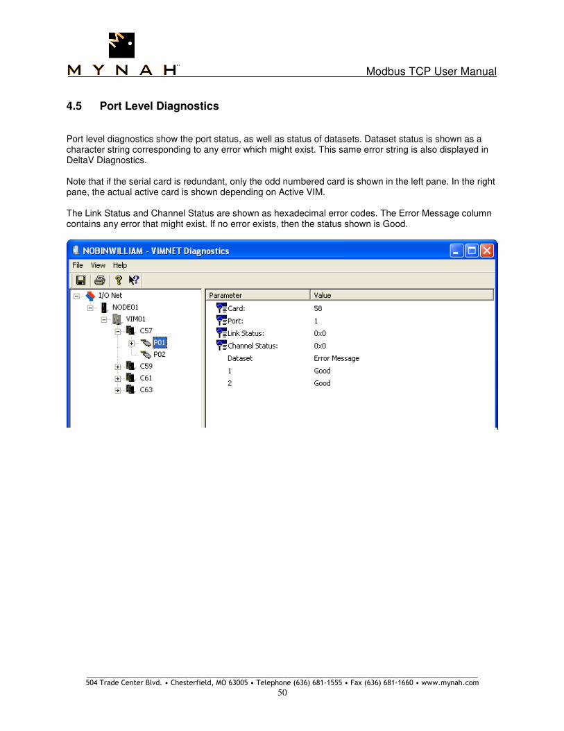
4.5 Port Level Diagnostics
Port level diagnostics show the port status, as well as status of datasets. Dataset status is shown as a character string corresponding to any error which might exist. This same error string is also displayed in DeltaV Diagnostics. Note that if the serial card is redundant, only the odd numbered card is shown in the left pane. In the right pane, the actual active card is shown depending on Active VIM. The Link Status and Channel Status are shown as hexadecimal error codes. The Error Message column contains any error that might exist. If no error exists, then the status shown is Good.

Modbus TCP User Manual
_____________________________________________________________________________________________________ 504 Trade Center Blvd. • Chesterfield, MO 63005 • Telephone (636) 681-1555 • Fax (636) 681-1660 • www.mynah.com
51
4.6 Device Level Diagnostics Device level diagnostics show the statistics for selected device as follows:
You can right click on the device to get a context menu as follows. This menu allows you to reset the statistics and also to search for configured datasets in this device.

Modbus TCP User Manual
_____________________________________________________________________________________________________ 504 Trade Center Blvd. • Chesterfield, MO 63005 • Telephone (636) 681-1555 • Fax (636) 681-1660 • www.mynah.com
52
4.7 Dataset Level Diagnostics By clicking on the individual dataset under Device diagnostics, you will get the dataset specific diagnostic information as follows:
Items of specific interest at this level are the Dataset Scan and the Time Between Scans. These pieces of information tell us what the scan time for this dataset is, and how much time elapses between two consecutive scans.

Modbus TCP User Manual
_____________________________________________________________________________________________________ 504 Trade Center Blvd. • Chesterfield, MO 63005 • Telephone (636) 681-1555 • Fax (636) 681-1660 • www.mynah.com
53
4.8 Diagnostics Datasets This VIMNet diagnostics information can also sent to DeltaV if diagnostics datasets are configured. There are two diagnostics dataset pages. Please refer to Section 5 for dataset configuration. The data transmitted to DeltaV datasets is as follows: Register Diagnostics Value R1 VIM Mode
O – Normal Online 1 – FailSafe Mode
R2 Number of Network devices
R3 Data Poll Queue
R4 Pending Message Queue
R5 Railbus Message Queue
R6 Counter - Serial Bus Poll
R7 Counter – Dataset Value Reads R8 Counter – Dataset Value Writes
R9 Counter – Default Reads
R10 Counter – Pending Data Reads
R11 Counter – Pending Data Writes
R12 Total number of Datasets
R13 Maximum DS Scan R14 Minimum DS Scan
R15 Average DS Scan
R16 Maximum Messages
R17 Minimum Messages
R18 Average Messages R19 Maximum Scan Time
R20 Minimum Scan Time
R21 Average Scan Time
R22 Ticker - Railbus message handler
R23 Ticker – Plug and Play message handler
R24 Ticker – Dataset handler R25 Rate of DS changes detected
R26 Rate of DS Polls received
R27 Logger IP address
R28 VIM Application type as configured 1 = ModbusTCP – cards 57-60 3 = ModbusTCP – cards 61-64 5 = ModbusTCP – Odd cards 57, 59, 61, 63 – if Odd cards Active 7 = ModbusTCP – Even cards 58, 60, 62, 64 – if Even cards Active
R29 Current redundancy State Bits 0-3 are the VIM State as follows: 0000 – Decommissioned 0001 – Commissioned 0010 – Flash Mode 0011 – Configuration Mode Bits 4-5 are the Redundancy state as follows: 00 – Simplex 01 – Redundant Active 02 – Redundant Backup Note that DeltaV always reads the Active VIM. Consequently this value should always be 0x11.
R30 VIM Revision number
R31 Free Buffers available
R32 Percent of free buffer available
R33 Buffer Resets
Table 3: VIMNet Diagnostics Dataset – Page 1

Modbus TCP User Manual
_____________________________________________________________________________________________________ 504 Trade Center Blvd. • Chesterfield, MO 63005 • Telephone (636) 681-1555 • Fax (636) 681-1660 • www.mynah.com
54
R34 Simplex VIM – Card 57 or 61 – Number of received message errors
R35 Simplex VIM – Card 58 or 62 – Number of received message errors
R36 Simplex VIM – Card 59 or 63 – Number of received message errors R37 Simplex VIM – Card 60 or 64 – Number of received message errors
R38 Simplex VIM – Card 57 or 61 – Number of received message timeouts
R39 Simplex VIM – Card 58 or 62 – Number of received message timeouts
R40 Simplex VIM – Card 59 or 63 – Number of received message timeouts
R41 Simplex VIM – Card 60 or 64 – Number of received message timeouts
R42 Simplex VIM – Card 57 or 61 – Number of received message retries R43 Simplex VIM – Card 58 or 62 – Number of received message retries
R44 Simplex VIM – Card 59 or 63 – Number of received message retries
R45 Simplex VIM – Card 60 or 64 – Number of received message retries
R46-R5 Simplex VIM – Reserved
R34 Redundant VIM – Card 57/58 – Number of received message errors
R35 Redundant VIM – Card 59/60 – Number of received message errors R36 Redundant VIM – Card 61/62 – Number of received message errors
R37 Redundant VIM – Card 63/64 – Number of received message errors
R38 Redundant VIM – Card 57/58 – Number of received message timeouts
R39 Redundant VIM – Card 59/60 – Number of received message timeouts
R40 Redundant VIM – Card 61/62 – Number of received message timeouts
R41 Redundant VIM – Card 63/64 – Number of received message timeouts R42 Redundant VIM – Card 57/58 – Number of received message retries
R43 Redundant VIM – Card 59/60 – Number of received message retries
R44 Redundant VIM – Card 61/62 – Number of received message retries
R45 Redundant VIM – Card 63/64 – Number of received message retries
R46 Redundant VIM – Reserved R47 Redundant VIM – Primary external device connection status bit mask for main IP
R48 Redundant VIM – Secondary external device connection status bit mask for secondary IP
R49 Redundant VIM – VIM external device status bit mask
R50 Redundant VIM – Reserved
Table 3: VIMNet Diagnostics Dataset – Page 1 (continued)
R1-R32 – Simplex IP Address of
external device Notes: Register contains IP address in use for communications with external device. User must check R33 to determine if device is connected. If register is 0, then no device exists at this index.
R1-R16 - Redundant
R33 Connected device mask
A bit set indicates the above reported IP address is connected. A bit clear indicates no connection or a failed connection. Bit 0 corresponds to IP address in register R1, Bit 1 corresponds to IP address in register R2, etc.
R34 Active VIM Odd cards=5; Even cards=7
R35 Primary Status Bit mask status of primary device connections. A bit value of 1 indicates connected, and a value of 0 indicated a disconnected device.
R36 Secondary Status Bit mask status of secondary device connections. A bit value of 1 indicates connected, and a value of 0 indicated a disconnected device.
R37-R50 Reserved
Table 4: VIMNet Diagnostics Dataset – Page 2
Note: Registers 34, 35 and 36 are available in VIM firmware version 3.9.2 and later.

Modbus TCP User Manual
_____________________________________________________________________________________________________ 504 Trade Center Blvd. • Chesterfield, MO 63005 • Telephone (636) 681-1555 • Fax (636) 681-1660 • www.mynah.com
55
5.0 Configuring DeltaV For each VIM module used, four Programmable Serial Cards must be configured in the DeltaV Explorer. A maximum of 2 VIM modules can be used with each DeltaV controller. The simplex serial cards required must be configured in slots 57-60, or 61-64. Redundant serial cards must be configured in pairs in slots 57/58, 59/60, 61/62, and 63/64. To add these cards, follow the steps below. Note that cards can also be added via the DeltaV Explorer, using the Auto-sense I/O cards menu option. All four cards must be configured, even if you are not using all of them. In addition, disable all unused serial card ports. In DeltaV, configure the serial card. This will create a Programmable Serial Card and define 2 ports under it, P01 and P02. Select the Card is redundant Checkbox if you are creating a redundant serial card.

Modbus TCP User Manual
_____________________________________________________________________________________________________ 504 Trade Center Blvd. • Chesterfield, MO 63005 • Telephone (636) 681-1555 • Fax (636) 681-1660 • www.mynah.com
56
1. Right mouse click on Port 1. The following dialog will appear.
Note
Make sure that you Enable the Port by clicking on the Enabled box. Unused ports should be left disabled.
Next, select the Advanced tab. In this dialog, select Master or Slave. Also select the message time parameters. All PLC devices configured under a given port will use the same time parameters. If the Mode is Master, all underlying devices in this port will be considered as external slaves to whom the VIM will connect. If Mode is Slave, then the underlying devices will be slaves to which one or more external masters will connect. Details of Send Outputs on Startup are discussed in Section 5.1.

Modbus TCP User Manual
_____________________________________________________________________________________________________ 504 Trade Center Blvd. • Chesterfield, MO 63005 • Telephone (636) 681-1555 • Fax (636) 681-1660 • www.mynah.com
57
Next, click the Communications tab. The following dialog will appear. These parameters are not used. Simply select the defaults and click OK.
2. Configure a Serial Device under the Port by doing a Right Mouse click and selecting New Serial
Device. The following dialog will appear:
Specify the device address and description. Valid device addresses are 1-254. Address 255 is reserved. Then click OK. This will add the serial device. The Device Address corresponds to the PLC device address, and must match the corresponding device configured in the VIMNet Explorer.

Modbus TCP User Manual
_____________________________________________________________________________________________________ 504 Trade Center Blvd. • Chesterfield, MO 63005 • Telephone (636) 681-1555 • Fax (636) 681-1660 • www.mynah.com
58
5.1 Configure Datasets Next, configure datasets in the Serial Device. Each Serial Device can have 16 datasets under it. Or you can have 16 devices with 1 dataset each. A dataset can be input or output. To add a new dataset, right mouse click on the Serial Device and select New Dataset. The following dialog will appear.
Configure the data direction to be input or output. In the above example, we are configuring an input dataset.

Modbus TCP User Manual
_____________________________________________________________________________________________________ 504 Trade Center Blvd. • Chesterfield, MO 63005 • Telephone (636) 681-1555 • Fax (636) 681-1660 • www.mynah.com
59
Next, click the DeltaV tab. The following dialog will appear:
In this dialog, configure the data type needed for DeltaV. You can see the available types by clicking on the drop down list. In the above example, we are configuring the input data type to be floating point. Please see Section 4.1 for additional details for this parameter. Next click the PLC tab. The following dialog will appear.

Modbus TCP User Manual
_____________________________________________________________________________________________________ 504 Trade Center Blvd. • Chesterfield, MO 63005 • Telephone (636) 681-1555 • Fax (636) 681-1660 • www.mynah.com
60
In this dialog, we will map DeltaV data types to PLC (or external Device) data types. PLC data type values and corresponding PLC registers are:
Device Data Type Device Register
0 COILS
1 INPUT STATUS
2 INPUT REGISTERS
3 HOLDING REGISTERS
6 VIM STATISTICS – Page 1
7 VIM STATISTICS – Page 2 8 Dataset Scan Control
All other values Reserved
Table 4: PLC Data Type Values and Registers
The Start Address specifies where in the PLC to read the data. In this example, the starting address is 0. This can be any PLC specific address. The starting address is specified as the offset, without the leading 1X, 3X or 4X. Maximum offset is 65535. The following table describes examples of PLC registers and corresponding start addresses in the dataset. The start address specified is actual offset address – 1. PLC address Start Address Description
1 0 First coil in PLC. Start address is specified as 0.
1 501 500 Coil 501. Start address is specified as 500.
501
10123 123 Input Status 10123 or 100123. Offset 123 is the specified Start address.
100123
31000 999 Input Register 31000 or 31000. Offset 999 is the specified Start address. 301000
40001 0 First Holding Register. Start address is specified as 0.
400001
40950 949 Holding Register 40950 or 400950. Start address specified as offset 949.
400950
Table 5: PLC Registers, Start Addresses, and Descriptions
For floating point and 32-bit DeltaV datasets reading PLC tables holding data in 16-bit registers, two 16-bit registers comprise a single value. The specified dataset Start address must be calculated accordingly. In this example, the starting address is 0, the PLC data type is 3 and the maximum number of values is 50. This would result in the following DeltaV registers.
DeltaV Register PLC or External Device Registers
R1 0 1
R2 2 3
R3 4 5
R50 98 99
Table 6: DeltaV and PLC Registers

Modbus TCP User Manual
_____________________________________________________________________________________________________ 504 Trade Center Blvd. • Chesterfield, MO 63005 • Telephone (636) 681-1555 • Fax (636) 681-1660 • www.mynah.com
61
In general, each dataset has a maximum of 100 16-bit values of DeltaV data type (as configured in the previous dialog). Each DeltaV value is mapped to one or more PLC registers. If two registers are required, as is the case for floating point values, the registers must be consecutive. The following table describes the mapping:
DeltaV Data Type PLC Register Type PLC Registers Required Max Number of Values
Boolean Coils Input Status
1 – Bit 100
Discrete Coils Input Status
1 – Bit 100
Signed 8 bit Integer Coils Input Status
1 – Bit or Byte 100
Signed 16 bit Integer Coils Input Status Input Registers Holding Registers
1 - 16 bit word 100
Signed 32 bit Integer Input Registers Holding Registers
2 - 16 bit words 50
Unsigned 8 bit Integer Coils Input Status
1 - 16 bit word 100
Unsigned 16 bit Integer Coils Input Status Input Registers Holding Registers
1 - 16 bit word 100
Unsigned 32 bit Integer Input Registers Holding Registers
2 - 16 bit word 50
Floating Point Input Registers Holding Registers
2 - 16 bit word 50
String Holding Registers
1 byte 100
Table 7a: Dataset Specification
PLC Register Type Modbus Function Code
Coils FC 1
Input Status FC 2
Input Registers FC 4
Holding Registers FC 3
Table 7b: Modbus Read Function Codes
PLC Register Type Output Dataset with
Output Mode Value Modbus Function Code
Coils 0 FC 15 1 FC 5
Holding Registers 0 FC 16
1 FC 6
Table 7c: Modbus Write Function Codes

Modbus TCP User Manual
_____________________________________________________________________________________________________ 504 Trade Center Blvd. • Chesterfield, MO 63005 • Telephone (636) 681-1555 • Fax (636) 681-1660 • www.mynah.com
62
Lastly, for each dataset click on the Special data tab. The following dialog will appear:
Special data 1 value is used when transferring data for Floating point, signed 32-bit integer and unsigned 32-bit integer registers. Special data 2 is used to indicate the number of registers used for Floating point and 32-bit integer values. Details of Special data usage are provided in the Customization section 5.7. Next, configure an output dataset in the Serial Device. The following dialog will appear.

Modbus TCP User Manual
_____________________________________________________________________________________________________ 504 Trade Center Blvd. • Chesterfield, MO 63005 • Telephone (636) 681-1555 • Fax (636) 681-1660 • www.mynah.com
63
Configure the data direction to be output. Select the Output mode. Output mode of 0 indicates Block outputs, i.e., the entire dataset is written out to the PLC if any dataset register changes. An Output mode of 1 indicates Single value output, i.e., only the value that has changed will be written out. See Table 7c above for Modbus function codes used. Output datasets can also be read back from the PLC by selecting the Output readback checkbox. Note that for Output datasets with readback, pending output changes always have precedence over field reads. However, after serial card download from the controller, the VIM provides a special data flag to force a field read prior to allowing the DeltaV controller to send a write. By using this flag, the controller will first receive the data contained in the field device, followed by any subsequent DeltaV control actions. Refer to Section 5.7 for additional details regarding this Read Before Write functionality. The port level Send Outputs on Startup parameter affects writes to external devices as described below. Simplex VIM – Send Outputs on Startup checkbox is Checked:
1. After VIM reboot (the controller automatically downloads the VIM serial cards), the default dataset values are written into the runtime database, and also written to the external device.
2. On card download, if dataset parameter changes are detected, i.e., number of values, start address, etc., have changed, the default dataset values are written into the runtime database, and the VIM also writes these values to the external device. Thereafter, all writes are on change of state driven by the DeltaV controller.
3. On card download, if no dataset parameter change is detected, the default dataset/register values
are ignored. Instead, the VIM writes the current dataset values for all output datasets to the external device. All other writes are driven by the DeltaV controller on change of state.
Simplex VIM – Send Outputs on Startup checkbox is Unchecked:
1. After VIM reboot (the controller automatically downloads the VIM serial cards), the default dataset values are written into the runtime database, but are not written to the external device.
2. On card download, if dataset parameter changes are detected, i.e., number of values, start address, etc., have changed, the default dataset values are written into the runtime database. If no dataset parameter changes are detected, the default data values are ignored.
3. All other writes are driven by the DeltaV controller on change of state.
Redundant VIM – Send Outputs on Startup checkbox is Checked:
1. After VIM reboot (the controller automatically downloads the VIM serial cards), the default dataset values are written into the runtime database, and also written to the external device.
2. On card download, if dataset parameter changes are detected, i.e., number of values, start address, etc., have changed, the default dataset values are written into the runtime database, and the VIM also writes these values to the external device. Thereafter, all writes are on change of state driven by the DeltaV controller.
3. On card download, if no dataset parameter change is detected, the default dataset values are
ignored. Instead, the VIM writes the current dataset values to the external device.

Modbus TCP User Manual
_____________________________________________________________________________________________________ 504 Trade Center Blvd. • Chesterfield, MO 63005 • Telephone (636) 681-1555 • Fax (636) 681-1660 • www.mynah.com
64
4. On VIM switchover, the current values are written to the external device.
5. All other writes to the external device are driven by DeltaV controller on change of state. Redundant VIM – Send Outputs on Startup checkbox is Unchecked:
1. After VIM reboot (the controller automatically downloads the VIM serial cards), the default dataset values are written into the runtime database, but are not written to the external device.
2. On card download, if dataset parameter changes are detected, i.e., number of values, start
address, etc., have changed, the default dataset values are written into the runtime database. If no dataset parameter change is detected, the default data values are ignored.
3. On VIM switchover, the current values are written to the external device.
4. All other writes to the external device are driven by DeltaV controller on change of state.
Next, click the DeltaV tab and select DeltaV data type as floating point.

Modbus TCP User Manual
_____________________________________________________________________________________________________ 504 Trade Center Blvd. • Chesterfield, MO 63005 • Telephone (636) 681-1555 • Fax (636) 681-1660 • www.mynah.com
65
Next, click the PLC tab. The following dialog will appear.
Note that the Data start address is now 100. This is because in our example, the first dataset has 50 floating-point values. Consequently, this dataset starts at R101.

Modbus TCP User Manual
_____________________________________________________________________________________________________ 504 Trade Center Blvd. • Chesterfield, MO 63005 • Telephone (636) 681-1555 • Fax (636) 681-1660 • www.mynah.com
66
5.2 Configuring a 16-bit dataset for Input/Holding Registers Here we discuss configuration of a 16-bit dataset to read 16-bit data. Follow steps one through four as above. You will be back to the dialog below:
Configure the data direction to be input or output. Click on the DeltaV tab as show below. View the drop down menu and choose 16-bit Unit with status. Click OK.

Modbus TCP User Manual
_____________________________________________________________________________________________________ 504 Trade Center Blvd. • Chesterfield, MO 63005 • Telephone (636) 681-1555 • Fax (636) 681-1660 • www.mynah.com
67
Click the PLC tab and configure Device data type. To read Input Registers or Holding Registers, the Device data type would be 2 or 3, respectively. The maximum number of values will be 100.
For each dataset, click on Special data and the following dialog will appear. If the byte order of 16-bit values read from the external device must be swapped, then configure Special data 1 = 1. If byte swapping is not required, configure a 0 in the registers. Click OK to close the dialog.

Modbus TCP User Manual
_____________________________________________________________________________________________________ 504 Trade Center Blvd. • Chesterfield, MO 63005 • Telephone (636) 681-1555 • Fax (636) 681-1660 • www.mynah.com
68
5.3 Configuring a 16-bit dataset for Coils/Input Status bits Here we discuss configuration of a 16-bit dataset to read coils or input status bits. Follow steps one through four as above. You will be back to the dialog below:
Configure the data direction to be input or output. Click on the DeltaV tab as show below. View the drop down menu and choose 16-bit Unit with status. Click OK.

Modbus TCP User Manual
_____________________________________________________________________________________________________ 504 Trade Center Blvd. • Chesterfield, MO 63005 • Telephone (636) 681-1555 • Fax (636) 681-1660 • www.mynah.com
69
Click the PLC tab and configure Device data type. To read Coils or Input Status bits, the Device data type would be 0 or 1, respectively. The maximum number of values will be 100.
For each dataset, click on Special data and the following dialog will appear.
Special Data 1 value and Special Data 5 bit 1 are used to control how the coil and input status bits are represented in the dataset registers. See Section 5.7 for additional details.

Modbus TCP User Manual
_____________________________________________________________________________________________________ 504 Trade Center Blvd. • Chesterfield, MO 63005 • Telephone (636) 681-1555 • Fax (636) 681-1660 • www.mynah.com
70
Special Data 5 (Bit 1) Special Data 1 value Description
0 0 The data read is stored as 1 bit per 8 or 16 bit register
1 0 For 8-bit Datasets – Each byte of received data is stored directly into the dataset registers in the order received. For 16-bit Datasets – Each pair of received data bytes are stored in the 16-bit registers in the order received. This is typically device dependent and is MSB,LSB.
1 1 or 4 For 8-bit Datasets – Each byte of received data is stored directly into the dataset registers in the order received. For 16-bit Datasets – Each pair of received data bytes are first swapped and then stored in the 16-bit registers.
If byte swapping is not required, configure a 0 in the registers. Click OK to close the dialog.

Modbus TCP User Manual
_____________________________________________________________________________________________________ 504 Trade Center Blvd. • Chesterfield, MO 63005 • Telephone (636) 681-1555 • Fax (636) 681-1660 • www.mynah.com
71
5.4 Configuring a Floating Point or 32-bit dataset Here we discuss configuration of a Floating Point or 32-bit dataset to read a device which represents each value as a single register (instead of 2 16-bit registers). Follow steps one through four as above. You will be back to the dialog below:
Configure the data direction to be input or output. Click on the DeltaV tab as show below. View the drop down menu and choose Floating Point with status. Select 32-bit with Status if this is a 32-bit dataset. Click OK.

Modbus TCP User Manual
_____________________________________________________________________________________________________ 504 Trade Center Blvd. • Chesterfield, MO 63005 • Telephone (636) 681-1555 • Fax (636) 681-1660 • www.mynah.com
72
Click the PLC tab and configure Device data type. To Device data type will always be 3 for Floating Point or 32-bit data. The maximum number of values will be 50.
For each dataset, click on Special data and the following dialog will appear.
Special Data 1 value and Special Data 2 bit 1 are used to customize representation of the floating point and 32-bit data. See Section 5.7 for additional details. If customization is not required, configure a 0 in the registers. Click OK to close the dialog.

Modbus TCP User Manual
_____________________________________________________________________________________________________ 504 Trade Center Blvd. • Chesterfield, MO 63005 • Telephone (636) 681-1555 • Fax (636) 681-1660 • www.mynah.com
73
5.5 Configuring a Boolean/Discrete dataset for Coils/Input Status data Follow steps one through four as above. You will be back to the dialog below:
Configure the data direction to be input or output. Click on the DeltaV tab as show below. View the drop down menu and choose Boolean with status (or Discrete with status). Click OK.

Modbus TCP User Manual
_____________________________________________________________________________________________________ 504 Trade Center Blvd. • Chesterfield, MO 63005 • Telephone (636) 681-1555 • Fax (636) 681-1660 • www.mynah.com
74
Click the PLC tab and configure Device data type. To read Coils or Input Status Registers, the Device data type would be 0 or 1, respectively. The maximum number of values will be 100.
Special data values are not used for Boolean and Discrete datasets. Click OK to close the dialog.

Modbus TCP User Manual
_____________________________________________________________________________________________________ 504 Trade Center Blvd. • Chesterfield, MO 63005 • Telephone (636) 681-1555 • Fax (636) 681-1660 • www.mynah.com
75
5.6 Configuring a dataset for VIM Diagnostics There are two diagnostic datasets available, Page 1 and Page 2. These are described below. First, add a new dataset. Select the Data direction as Input. Please see Section 4, Table 3 for diagnostic data available in these datasets.
A special case of this dataset is to allow user control of redundancy switching at the DeltaV Control Module level. This capability is enabled only if the VIM is configured as redundant. In this case, this dataset should be configured with Data direction as Output, and the Output read back checkbox should be checked as follows:

Modbus TCP User Manual
_____________________________________________________________________________________________________ 504 Trade Center Blvd. • Chesterfield, MO 63005 • Telephone (636) 681-1555 • Fax (636) 681-1660 • www.mynah.com
76
Configure the data direction to be input or output, as required for your application. Next, click on the DeltaV tab as show below. View the drop down menu and choose 32 bit unit w/Status. Click OK.

Modbus TCP User Manual
_____________________________________________________________________________________________________ 504 Trade Center Blvd. • Chesterfield, MO 63005 • Telephone (636) 681-1555 • Fax (636) 681-1660 • www.mynah.com
77
Click the PLC tab and configure Device data type. For Page 1 VIM Diagnostics, enter the Device data type as 6. For Page 2 VIM Diagnostics, enter the Device data type as 7. The Data start address will always be 0, and the Number of values will be 50.
Special data values are not used for this dataset. Click OK to close the dialog.

Modbus TCP User Manual
_____________________________________________________________________________________________________ 504 Trade Center Blvd. • Chesterfield, MO 63005 • Telephone (636) 681-1555 • Fax (636) 681-1660 • www.mynah.com
78
5.7 Customization The VIM firmware allows you to customize ModbusTCP communications and representation of data. Modification of data representation is typically only required when reading/writing Floating Point, or Signed/Unsigned 32-bit Integer registers. However, in some cases, you may need to use Special data 1 for 16-bit byte swapping as well. To customize data representation in a data set, you can use the Special data 1 and 2 registers as flags. Assume a Floating-point number 123.45, and its representation in IEEE 754 format as follows:
Floating Point Number Representation as 2 16-bit words Representation as 4 bytes
123.45 58982, 17142 230, 102, 66, 246
Special Data 1 Value and Description
DeltaV Data Type is Floating Point or 32-bit
Floating point representation described above. 0 – Default is no customization – Floating Point and 32-bit data is represented as received. The transmitted byte order is 230, 102, 66, 246 1 – The transmitted byte order is 66, 246, 230, 102 2 – The transmitted byte order is 246, 66, 102, 230 3 – The transmitted byte order is 102, 230, 246, 66
DeltaV Data Type is 16-Bit
0 – Default order is MSB-LSB 1 or 4 – Bytes are swapped to LSB-MSB
Special Data 2 Bit Mask Value and Description
DeltaV Data Type is Floating Point or 32-bit; PLC Data Type is 16-bit or Floating Point/32-bit
0 – Default setting where 2 Modbus 16-bit registers are equivalent to 1 Floating Point or 32-bit value in DeltaV. There is a 1-2 correspondence between DeltaV value and read values. 1 – Data is not read as 2 MODBUS 16-bit registers but as individual Floating Point or 32-bit values. There is a 1-1 correspondence between DeltaV value and read value.
DeltaV Data Type is 8-Bit or String; PLC Data Type is 16-bit
0 – Low byte of 16-bit register data is stored per 8-bit or character. High byte is discarded. 1 – Low byte of 16-bit register data is stored per 8-bit or character. High byte is stored in the next 8-bit or character. 2 – When writing to the PLC, two characters are used to make 1 16-bit register. If this flag is set, the string bytes are swapped.
Read before Write 256 – Used only for datasets configured as Output with Readback. If this flag is set, following a VIM restart/reboot or download from DeltaV with a configuration change, the VIM will first read the external device and report the dataset to the DeltaV Controller before allowing any writes from the Controller out to the device. This flag is not used upon redundancy switchover. When a switchover occurs, the current output data is written to the newly active VIM by the Controller, and the VIM sends this data to the external device.
Discard Write 32768 – By default, when a switchover occurs, the current output data is written to the newly active VIM by the Controller, and the VIM sends this data to the external device. For Output datasets, if this flag is set, the pending output is discarded after VIM restart/reboot or switchover.

Modbus TCP User Manual
_____________________________________________________________________________________________________ 504 Trade Center Blvd. • Chesterfield, MO 63005 • Telephone (636) 681-1555 • Fax (636) 681-1660 • www.mynah.com
79
To customize communications for a specific data set, the Special data 3 and 4 registers are used as described below.
Special Data 3 Value and Description
This is a delay parameter specified in 5ms units. When specified, it overrides the port Transmit delay for this dataset. The driver will delay for this amount of time before reading/writing the dataset. 1 = 5ms, 2 = 10ms, etc
Special Data 4 Value and Description
This is a delay parameter specified in 5ms units. It applies only to datasets configured as Output, and Output mode 0 (block output). When specified, it provides a cyclic write of current dataset values from the VIM database to external devices. Note that normal functionality is for the VIM to write output data only when a change of state is detected. 1 = 5ms, 2 = 10ms, etc

Modbus TCP User Manual
_____________________________________________________________________________________________________ 504 Trade Center Blvd. • Chesterfield, MO 63005 • Telephone (636) 681-1555 • Fax (636) 681-1660 • www.mynah.com
80
To customize special case communications, the Special data 5 register is used as a bit mask described below. See Section 6.1 for additional description.
Special Data 5 - Low Byte
Description Bit Mask Value
Data Fan In/Out Flag – If set, this flag forces data fan in/out storage based in Special Data 1 and 2 flags as described below. This flag only affects input datasets reading coils or input status bits, and the dataset type is 8-bit, 16-bit or 32-bit. For Dataset Data Type = 8-bit, 16-bit, or 32-bit, and PLC data type is Coil or Input Status: If flag is 0, each bit value is stored in a separate dataset register. If flag is 1, the received bytes are stored without being fanned out. Special Data 1 value of 1 or 4 determines byte order. For Dataset Data Type = 8-bit, 16-bit, or String, and PLC data type is 16-bit: Special Data 2 value determines byte order and storage.
1
Ping Flag - Configure this flag only on the first dataset of the device. If this flag is set, the VIM uses Network ICMP ping. Otherwise, the VIM uses Modbus Function 8 message as ping. This flag is used in Redundant mode only. See section 6.2 for additional details.
2
Bridge Device - Configure this flag only on the first dataset of the device. If this flag is set, the VIM considers the device as Bridge Device (with underlying serial devices). Bridge devices and Gateway devices are mutually exclusive.
4
One Connection only - Configure this flag only on the first dataset of the device. If this flag is set, the VIM opens only one network connection to the device (by default, the VIM opens 2 connections). This is used in cases where the device does not support multiple simultaneous connections. This flag is used in Redundant mode only when communicating with a simplex device which only allows 1 connection. In this case, the standby VIM does not open any connections to the device. It is recommended that the standby VIM use an ICMP ping to ensure the device is present.
8
Device ID 0 - Configure this flag on all device datasets. For external slaves, the VIM driver always sends the configured device ID as part of the ModbusTCP packet. However, some devices do not support this and expect the device ID to be specified as 0. If the flag is set for a dataset, then the VIM will send a device ID of 0 when reading/writing the data for that dataset. All other datasets are governed by their own Special Data 5 registers. 1 Note: This device ID override functionality is only available for RTU TCP type communications, i.e.,
communications using the Open ModbusTCP standard. Other communications using the RTU VIA TCP or RTU VIA UDP do not have this support. If both flags (16 + 32) are specified, then the device ID used is 255.
16
Device ID 1 - Configure this flag on all device datasets. For external slaves, the VIM driver always sends the configured device ID as part of the ModbusTCP packet. However, some devices do not support this and expect the device ID to be specified as 1. If the flag is set for a dataset, then the VIM will send a device ID of 1 when reading/writing the data for that dataset. All other datasets are governed by their own Special Data 5 registers. See
1Note above.
If both flags (16 + 32) are specified, then the device ID used is 255.
32

Modbus TCP User Manual
_____________________________________________________________________________________________________ 504 Trade Center Blvd. • Chesterfield, MO 63005 • Telephone (636) 681-1555 • Fax (636) 681-1660 • www.mynah.com
81
Use Primary IP only. Configure this flag only on the first dataset of the device. This flag is used in Redundant mode only. By default, VIM A and VIM B both open two connections each to each IP of the external device. The external device is expected to have two IP addresses, IP A and IP B. Hence, 4 connections are opened, two on IP A and two on IP B. For example, if VIM A is Active, then on loss of communication with device IP A, the VIM starts using device IP B without requesting a switchover. This flag is used in cases where the device has two chassis (e.g., primary and hot standby) with two available IP addresses. Upon loss of communications on the active chassis, the hot standby takes over and also assumes the IP address of the down chassis. If this flag is set, then VIM A opens only one network connection to primary chassis IP A, and VIM B also opens only one connection to hot standby chassis IP B. From the VIM perspective, regardless of which VIM is active, it is always communicating only with the designated primary IP address (IP A).
64
Use consecutive ports. Configure this flag only on the first dataset of the device. This flag is used in Redundant mode only. By default, VIM A and VIM B both use the same configured network port number for communications, e.g., 502. Both IP addresses of the external device are expected to respond on the given port number. If this flag is set, the VIM A opens only one network connection to device IP A using the configured port number, and VIM B also opens only one connection to device IP B, using the configured port number + 1. This flag is used in cases where the device does not support: (1) multiple simultaneous connections; (2) device IP A and device IP B must use different port numbers; or (3) device IP A and device IP B are on different networks.
128
One-on-one communications. Configure this flag only on the first dataset of the device. This flag is used in Redundant mode only. By default, VIM A and VIM B both open two connections each to the external device. The external device is expected to have two IP addresses, IP A and IP B. On loss of communication with device IP A, the VIM A starts using device IP B without requesting a switchover. If this flag is set, VIM A opens only one network connection to device IP A, and VIM B also opens only one connection to device IP B. VIM A always communicates only with IP A, and VIM B always communicates only with IP B. If VIM A is active and losses communications with device IP A, a switchover will occur and VIM B will become active, communicating with device IP B. This flag is used in cases where the device has fixed IP addresses (non switching) and does not support: (1) multiple simultaneous connections; (2) device IP A and device IP B must use different port numbers; or (3) device IP A and device IP B are on different networks.
256
Special Data 5 - High Byte (Most Significant 7 bits)
Use to specify Ping Delay. Configure this value only on the first dataset of the device. This value is used in Redundant mode only to specify the ping delay in 100ms units used by the standby VIM. There are two types of pings. A Function 8 ping (default) and a network ICMP ping. If the value is 0 and the network ICMP has been configured, then the ping is issued every 5 seconds. If the VIM uses Function 8 ping, then the default ping delay is 1500ms. If this value is specified, then both Function 8 or ICMP pings are issued based on this ping delay. Also refer to Section 6.2.
1=100ms

Modbus TCP User Manual
_____________________________________________________________________________________________________ 504 Trade Center Blvd. • Chesterfield, MO 63005 • Telephone (636) 681-1555 • Fax (636) 681-1660 • www.mynah.com
82
5.8 Dataset Scan Control By default, the VIM performs dataset scans as fast as the network request/response allows. All datasets of each device are continuously scanned in a cycle. All devices are scanned simultaneously. The port level Message Timeout value, in milliseconds, is configured to discard outstanding data requests to non-response devices. However, the maximum time value can be 25500ms. In some cases, this time value is insufficient. Consequently, an extended timeout time is required. An alternate scan control mechanism is built into the VIM to allow a DeltaV Control Module to trigger dataset scans, on demand, by writing to a special scan control dataset. The scan control dataset is not part of the VIM scan. It affects Input and Output with Readback datasets only. That is, only the reading of field data is controlled by this dataset. If not configured, all VIM scans work by default, as described above. If the dataset is configured, then field reads may be controlled as described below. This dataset may be configured only once for the entire VIM, and may reside under any configured device. Write requests from DeltaV to the external devices are always handled by exception, and are not a part of the above scan mechanism. Writes have priority over reads. For Output with Readback datasets, only the field read part is controlled by the above mechanism. Any one dataset out of the 128 available may be configured to be the scan control dataset. Excluding the scan control dataset, all remaining 127 datasets are controlled. The scan control dataset is configured as follows:
Data Direction Output with Readback
DeltaV Data Type 16-Bit Unsigned Integer
Device Data Type 8
Start Address 0
Number of Values 32
Special Data Values (1 to 5) 0, 0, 0, 0, 0
The dataset is divided into 4 sections:
1. Registers 1-8 are designated for scan control trigger bits; 2. Registers 9-16 are designated to specify if a dataset is to be scanned based on scan control; 3. Registers 17-24 are designated to hold the extended timeout value; and 4. Registers 25-32 are designated to completely disable the scan of selected dataset.

Modbus TCP User Manual
_____________________________________________________________________________________________________ 504 Trade Center Blvd. • Chesterfield, MO 63005 • Telephone (636) 681-1555 • Fax (636) 681-1660 • www.mynah.com
83
Dataset Scan Trigger Registers R1-R8 are used as a bit mask. A bit set to 1 by the DeltaV Control Module triggers scan of the corresponding dataset. By default, all bits are 0. On normal scan completion or a timeout, the bit is reset to 0. Bit 1 of the register corresponds to Dataset 1, and bit 16 corresponds to Dataset 16. Bits corresponding to unconfigured datasets are ignored.
R1 Controls all 16 datasets in Simplex C57 Port 1 or C61 Port 1, and Redundant C57/58 Port 1.
R2 Controls all 16 datasets in Simplex C57 Port 2 or C61 Port 2, and Redundant C57/58 Port 2.
R3 Controls all 16 datasets in Simplex C58 Port1 or C62 Port 1, and Redundant C59/60 Port 1.
R4 Controls all 16 datasets in Simplex C58 Port 2 or C62 Port 2, and Redundant C59/60 Port 2.
R5 Controls all 16 datasets in Simplex C59 Port 1 or C63 Port 1, and Redundant C61/62 Port 1.
R6 Controls all 16 datasets in Simplex C59 Port 2 or C63 Port 2, and Redundant C61/62 Port 2.
R7 Controls all 16 datasets in Simplex C60 Port 1 or C64 Port 1, and Redundant C63/64 Port 1.
R8 Controls all 16 datasets in Simplex C60 Port 2 or C64 Port 2, and Redundant C63/64 Port 2.
Controlled Dataset Registers R9-R16 are a bit mask specifying if a dataset is part of the scan control mechanism. A bit value of 0 implies that the corresponding dataset is not part of scan control (0 by default). Such a dataset will be scanned continuously. If a bit is set to 1, then the dataset will be scanned only if the corresponding bit in registers R1-8 is also set. The VIM does not change the value of registers R9-R16.
R9 Enables/Disables scan control of all 16 datasets in Simplex C57 Port 1 or C61 Port 1, and Redundant C57/58 Port 1.
R10 Enables/Disables scan control of all 16 datasets in Simplex C57 Port 2 or C61 Port 2, and Redundant C57/58 Port 2.
R11 Enables/Disables scan control of all 16 datasets in Simplex C58 Port1 or C62 Port 1, and Redundant C59/60 Port 1.
R12 Enables/Disables scan control of all 16 datasets in Simplex C58 Port 2 or C62 Port 2, and Redundant C59/60 Port 2.
R13 Enables/Disables scan control of all 16 datasets in Simplex C59 Port 1 or C63 Port 1, and Redundant C61/62 Port 1.
R14 Enables/Disables scan control of all 16 datasets in Simplex C59 Port 2 or C63 Port 2, and Redundant C61/62 Port 2.
R15 Enables/Disables scan control of all 16 datasets in Simplex C60 Port 1 or C64 Port 1, and Redundant C63/64 Port 1.
R16 Enables/Disables scan control of all 16 datasets in Simplex C60 Port 2 or C64 Port 2, and Redundant C63/64 Port 2.

Modbus TCP User Manual
_____________________________________________________________________________________________________ 504 Trade Center Blvd. • Chesterfield, MO 63005 • Telephone (636) 681-1555 • Fax (636) 681-1660 • www.mynah.com
84
Extended Timeout Time For R17-R24, a non-zero number specifies the message timeout time value to be used, instead of the default port level timeout. The time units are 5 seconds per count. If the register contains a 2, then all datasets under the corresponding port will timeout after 10 seconds. The maximum value can be 65535, which amounts to a timeout of 91 hours.
R17 Timeout value for Simplex C57 Port 1 or C61 Port 1, and Redundant C57/58 Port 1.
R18 Timeout value for Simplex C57 Port 2 or C61 Port 2, and Redundant C57/58 Port 2.
R19 Timeout value for Simplex C58 Port1 or C62 Port 1, and Redundant C59/60 Port 1.
R20 Timeout value for Simplex C58 Port 2 or C62 Port 2, and Redundant C59/60 Port 2.
R21 Timeout value for Simplex C59 Port 1 or C63 Port 1, and Redundant C61/62 Port 1.
R22 Timeout value for Simplex C59 Port 2 or C63 Port 2, and Redundant C61/62 Port 2.
R23 Timeout value for Simplex C60 Port 1 or C64 Port 1, and Redundant C63/64 Port 1.
R24 Timeout value for Simplex C60 Port 2 or C64 Port 2, and Redundant C63/64 Port 2. Dataset Scan Disable R25-R32 are a bit mask specifying if the scan of a dataset has been completely disabled. A bit value of 0 implies that the corresponding dataset is part of the scan, either controller or continuous. Note that the values are 0 by default. If a bit is set to 1, then the dataset will not be scanned. Instead, an error will be reported to DeltaV Diagnostics indicating the dataset state (“Disabled Dataset via Scan
Control”). In this way the datasets of one or more devices may be removed from the scan if the
devices are down for maintenance. Scan of all other devices will continue to function normally. The VIM does not change the value of registers R25-R32.
R25 Enables/Disables scan of all 16 datasets in Simplex C57 Port 1 or C61 Port 1, and Redundant C57/58 Port 1.
R26 Enables/Disables scan of all 16 datasets in Simplex C57 Port 2 or C61 Port 2, and Redundant C57/58 Port 2.
R27 Enables/Disables scan of all 16 datasets in Simplex C58 Port1 or C62 Port 1, and Redundant C59/60 Port 1.
R28 Enables/Disables scan of all 16 datasets in Simplex C58 Port 2 or C62 Port 2, and Redundant C59/60 Port 2.
R29 Enables/Disables scan of all 16 datasets in Simplex C59 Port 1 or C63 Port 1, and Redundant C61/62 Port 1.
R30 Enables/Disables scan of all 16 datasets in Simplex C59 Port 2 or C63 Port 2, and Redundant C61/62 Port 2.
R31 Enables/Disables scan of all 16 datasets in Simplex C60 Port 1 or C64 Port 1, and Redundant C63/64 Port 1.
R32 Enables/Disables scan of all 16 datasets in Simplex C60 Port 2 or C64 Port 2, and Redundant C63/64 Port 2.

Modbus TCP User Manual
_____________________________________________________________________________________________________ 504 Trade Center Blvd. • Chesterfield, MO 63005 • Telephone (636) 681-1555 • Fax (636) 681-1660 • www.mynah.com
85
5.9 Configuring Master/Slave Functionality A Simplex VIM can behave as a Master to external slave devices, and as a slave to external Masters. A pair of VIMs on a network can also exchange data with each other. Both VIMs can simultaneously be Master and Slave. The following is an example, explaining how to configure one ModbusTCP VIM as master and another one as slave. It shows the configuration parameters for both master and slave VIM. In addition it demonstrates how to configure one of VIM’s ports as slave and the other as master. VIMNet Explorer Configuration of VIM01 In the VIMNet Explorer, add a Modbus TCP VIM placeholder. Specify an IP address and subnet mask as required. Next, commission the VIM.
Add an external slave device with device address 1 and IP address 10.22.6.2 to serial card C57, port P01.

Modbus TCP User Manual
_____________________________________________________________________________________________________ 504 Trade Center Blvd. • Chesterfield, MO 63005 • Telephone (636) 681-1555 • Fax (636) 681-1660 • www.mynah.com
86
Add a second device which will represent this VIM as slave to the external VIM master. Note that it shares the VIMs IP address.
Upload the configuration to the master VIM. Right click on the VIM placeholder and select VIM Configuration Upload as shown below.

Modbus TCP User Manual
_____________________________________________________________________________________________________ 504 Trade Center Blvd. • Chesterfield, MO 63005 • Telephone (636) 681-1555 • Fax (636) 681-1660 • www.mynah.com
87
VIMNet Explorer Configuration of VIM02 In the VIMNet Explorer, add a Modbus TCP VIM placeholder. Specify an IP address and subnet mask as required. Next, commission the VIM.
Add an external slave device with device address 1 and IP address 10.22.6.1.
Also add a second device which will represent this VIM as slave to the external VIM master. Note that it shares the VIMs IP address.

Modbus TCP User Manual
_____________________________________________________________________________________________________ 504 Trade Center Blvd. • Chesterfield, MO 63005 • Telephone (636) 681-1555 • Fax (636) 681-1660 • www.mynah.com
88
Next, upload the configuration to the VIM. Right click on the VIM placeholder and select VIM Configuration Upload as shown below.
With both VIMs configured, we now have VIM01 reading from VIM02, and VIM02 reading from VIM01. Next we configure the DeltaV Controllers and datasets.

Modbus TCP User Manual
_____________________________________________________________________________________________________ 504 Trade Center Blvd. • Chesterfield, MO 63005 • Telephone (636) 681-1555 • Fax (636) 681-1660 • www.mynah.com
89
DeltaV Configuration of VIM01 The DeltaV configuration of datasets is very simple. It starts by Auto-sensing for new IO cards. Once the 4 Programmable Serial cards are inserted into the Controller I/O tree, we can configure the Ports, Devices and Datasets. VIM01 will be configured with a Master and a Slave Port. As Master, the VIM will read data from the Slave port/device in VIM02. As Slave, the VIM will accept a connection from the Master port/device in VIM02. Configure VIM01 Master Port In order to start configuring devices, first choose the serial card and expand it to see the ports. Right mouse click on port P01 and go to Properties. Check the checkbox to enable this port as shown below.
This port will be configured as Master. Click on Advanced tab and select Master (default selection).
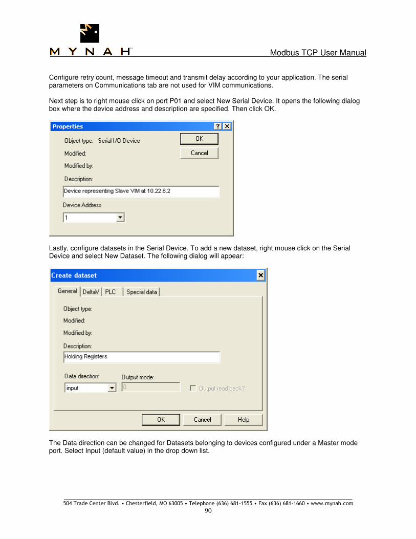
Modbus TCP User Manual
_____________________________________________________________________________________________________ 504 Trade Center Blvd. • Chesterfield, MO 63005 • Telephone (636) 681-1555 • Fax (636) 681-1660 • www.mynah.com
90
Configure retry count, message timeout and transmit delay according to your application. The serial parameters on Communications tab are not used for VIM communications. Next step is to right mouse click on port P01 and select New Serial Device. It opens the following dialog box where the device address and description are specified. Then click OK.
Lastly, configure datasets in the Serial Device. To add a new dataset, right mouse click on the Serial Device and select New Dataset. The following dialog will appear:
The Data direction can be changed for Datasets belonging to devices configured under a Master mode port. Select Input (default value) in the drop down list.
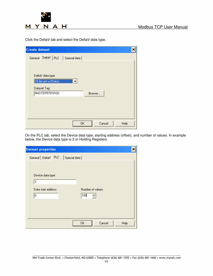
Modbus TCP User Manual
_____________________________________________________________________________________________________ 504 Trade Center Blvd. • Chesterfield, MO 63005 • Telephone (636) 681-1555 • Fax (636) 681-1660 • www.mynah.com
91
Click the DeltaV tab and select the DeltaV data type.
On the PLC tab, select the Device data type, starting address (offset), and number of values. In example below, the Device data type is 3 or Holding Registers.
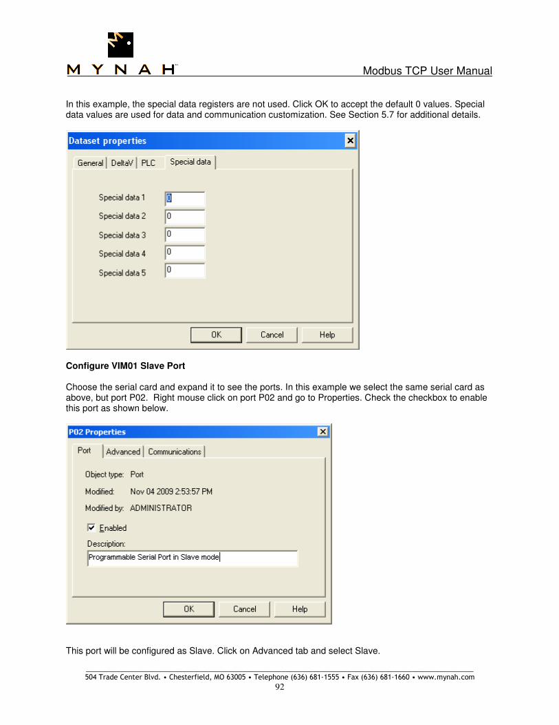
Modbus TCP User Manual
_____________________________________________________________________________________________________ 504 Trade Center Blvd. • Chesterfield, MO 63005 • Telephone (636) 681-1555 • Fax (636) 681-1660 • www.mynah.com
92
In this example, the special data registers are not used. Click OK to accept the default 0 values. Special data values are used for data and communication customization. See Section 5.7 for additional details.
Configure VIM01 Slave Port Choose the serial card and expand it to see the ports. In this example we select the same serial card as above, but port P02. Right mouse click on port P02 and go to Properties. Check the checkbox to enable this port as shown below.
This port will be configured as Slave. Click on Advanced tab and select Slave.

Modbus TCP User Manual
_____________________________________________________________________________________________________ 504 Trade Center Blvd. • Chesterfield, MO 63005 • Telephone (636) 681-1555 • Fax (636) 681-1660 • www.mynah.com
93
The serial parameters under Communications tab are not used for VIM communications. Next step is to right mouse click on port P02 and select New Serial Device. It opens the following dialog box where the device address and description are specified. Then click OK.
Lastly, configure datasets in the Serial Device. To add a new dataset, right mouse click on the Serial Device and select New Dataset. The following dialog will appear:

Modbus TCP User Manual
_____________________________________________________________________________________________________ 504 Trade Center Blvd. • Chesterfield, MO 63005 • Telephone (636) 681-1555 • Fax (636) 681-1660 • www.mynah.com
94
The Data direction cannot be changed for Datasets belonging to devices configured under a Slave mode port. Click the DeltaV tab and select the DeltaV data type.
On the PLC tab, select the Device data type, starting address (offset), and number of values. In example below, the Device data type is 3 or Holding Registers.

Modbus TCP User Manual
_____________________________________________________________________________________________________ 504 Trade Center Blvd. • Chesterfield, MO 63005 • Telephone (636) 681-1555 • Fax (636) 681-1660 • www.mynah.com
95
In this example, the special data registers are not used. Click OK to accept the default 0 values. Special data values are used for data and communication customization. See Section 5.7 for additional details.

Modbus TCP User Manual
_____________________________________________________________________________________________________ 504 Trade Center Blvd. • Chesterfield, MO 63005 • Telephone (636) 681-1555 • Fax (636) 681-1660 • www.mynah.com
96
DeltaV Configuration of VIM02 VIM02 will be configured with a Master and a Slave Port. As Master, the VIM will read data from the Slave port/device in VIM01. As Slave, the VIM will accept a connection from the Master port/device in VIM01. Configure VIM01 Master Port In order to start configuring devices, first choose the serial card and expand it to see the ports. Right mouse click on port P01 and go to Properties. Check the checkbox to enable this port as shown below.
This port will be configured as Master. Click on Advanced tab and select Master (default selection).

Modbus TCP User Manual
_____________________________________________________________________________________________________ 504 Trade Center Blvd. • Chesterfield, MO 63005 • Telephone (636) 681-1555 • Fax (636) 681-1660 • www.mynah.com
97
Configure retry count, message timeout and transmit delay according to your application. The serial parameters on Communications tab are not used for VIM communications. Next step is to right mouse click on port P01 and select New Serial Device. It opens the following dialog box where the device address and description are specified. Then click OK.
Lastly, configure datasets in the Serial Device. To add a new dataset, right mouse click on the Serial Device and select New Dataset. The following dialog will appear:
The Data direction can be changed for Datasets belonging to devices configured under a Master mode port. Select Input (default value) in the drop down list.

Modbus TCP User Manual
_____________________________________________________________________________________________________ 504 Trade Center Blvd. • Chesterfield, MO 63005 • Telephone (636) 681-1555 • Fax (636) 681-1660 • www.mynah.com
98
Click the DeltaV tab and select the DeltaV data type.
On the PLC tab, select the Device data type, starting address (offset), and number of values. In example below, the Device data type is 3 or Holding Registers.

Modbus TCP User Manual
_____________________________________________________________________________________________________ 504 Trade Center Blvd. • Chesterfield, MO 63005 • Telephone (636) 681-1555 • Fax (636) 681-1660 • www.mynah.com
99
In this example, the special data registers are not used. Click OK to accept the default 0 values. Special data values are used for data and communication customization. See Section 5.7 for additional details.
Configure VIM01 Slave Port Choose the serial card and expand it to see the ports. In this example we select the same serial card as above, but port P02. Right mouse click on port P02 and go to Properties. Check the checkbox to enable this port as shown below.
This port will be configured as Slave. Click on Advanced tab and select Slave.

Modbus TCP User Manual
_____________________________________________________________________________________________________ 504 Trade Center Blvd. • Chesterfield, MO 63005 • Telephone (636) 681-1555 • Fax (636) 681-1660 • www.mynah.com
100
The serial parameters under Communications tab are not used for VIM communications. Next step is to right mouse click on port P02 and select New Serial Device. It opens the following dialog box where the device address and description are specified. Then click OK.
Lastly, configure datasets in the Serial Device. To add a new dataset, right mouse click on the Serial Device and select New Dataset. The following dialog will appear:

Modbus TCP User Manual
_____________________________________________________________________________________________________ 504 Trade Center Blvd. • Chesterfield, MO 63005 • Telephone (636) 681-1555 • Fax (636) 681-1660 • www.mynah.com
101
The Data direction cannot be changed for Datasets belonging to devices configured under a Slave mode port. Click the DeltaV tab and select the DeltaV data type.
On the PLC tab, select the Device data type, starting address (offset), and number of values. In example below, the Device data type is 3 or Holding Registers.

Modbus TCP User Manual
_____________________________________________________________________________________________________ 504 Trade Center Blvd. • Chesterfield, MO 63005 • Telephone (636) 681-1555 • Fax (636) 681-1660 • www.mynah.com
102
In this example, the special data registers are not used. Click OK to accept the default 0 values. Special data values are used for data and communication customization. See Section 5.7 for additional details.

Modbus TCP User Manual
_____________________________________________________________________________________________________ 504 Trade Center Blvd. • Chesterfield, MO 63005 • Telephone (636) 681-1555 • Fax (636) 681-1660 • www.mynah.com
103
Following screen capture shows the Slave statistics in VIMNet Diagnostics. Note for VIM01, the external master IP address is 10.22.6.2 which is VIM02. And for VIM02, the external master IP address is 10.22.6.1 which is VIM01.

Modbus TCP User Manual
_____________________________________________________________________________________________________ 504 Trade Center Blvd. • Chesterfield, MO 63005 • Telephone (636) 681-1555 • Fax (636) 681-1660 • www.mynah.com
104
6.0 Redundant I/O Communications Four types of communications connections are supported for redundant VIMs. These are described below. For each external device connected to the VIMs, the corresponding redundancy type must be configured in the VIMNet Explorer. See Section 3.5. Current firmware release supports 32 external devices in simplex mode and 16 in redundant mode.
6.1 Redundancy Theory of Operations The redundant VIM pair can connect to three types of external devices:
1. Simplex devices: Such devices have only one IP address. Both Active and Standby VIMs must connect to the same IP address. Hence the device is expected to have available 2 network connections on the same IP address.
2. Devices which switch IP addresses, depending on Active state: Quantum PLC deployed in the HSBY (hot standby) architecture is an example. Two IP addresses (primary and secondary) are configured for such devices.
3. Devices with fixed IP addresses, regardless of Active state. Non HSBY Quantum PLC’s, Triconex, Triplex, Bently Nevada, etc, are examples of such devices. Two IP addresses (primary and secondary) are configured for such devices.
In some cases, connectivity to external devices presents unique challenges. These are described below. In general, the Active VIM opens two connections to each configured external device, one with the primary IP address and one with the secondary IP address. Similarly, the Standby VIM also opens two connections, one with the primary IP address and one with the secondary IP address. All connections, taken together, determine if a external device is available or not. Device availability is represented as a bit mask. A bit set indicates a present device. The mask of available devices is visible under VimNet Diagnostics. For proper functionality, it is expected that the external device supports multiple connections on each configured IP address.
Because some devices do not support more than one network connection per IP address, the above VIM mechanism causes connectivity issues. Various flags and options have been built into the VIM firmware to allow users to customize communications as required. See Section 5.7. For example, if the external device only supports one network connection, the user can configure the VIM to open only one connection. Consequently, the Active VIM opens one connection to the primary IP, and the backup VIM opens one connection to the secondary IP.
Under normal communication state with two open connections on each IP, the connection to the primary address is used for data exchange. The connection to the secondary IP address is serviced with a Modbus Function 8 Diagnostic message, i.e., a ping. Upon loss of communications on the primary connection, the Active VIM does not request switchover. Instead, it starts using the secondary connection for the data exchange. Subsequently, if the secondary connection also fails, then a switchover is requested. The final switchover decision is based on which VIM has the best external device availability mask. If the primary connection has failed, the VIM periodically tries reconnecting it. Upon success, the VIM switches back to using the primary connection for data exchange, and starts sending Diagnostic messages (pings) to the secondary connection. Note that loss of a single connection does not constitute loss of the external device.

Modbus TCP User Manual
_____________________________________________________________________________________________________ 504 Trade Center Blvd. • Chesterfield, MO 63005 • Telephone (636) 681-1555 • Fax (636) 681-1660 • www.mynah.com
105
The Secondary VIM also opens two connections to the configured external devices, one with the primary IP address and one with the secondary IP address. Both connections are serviced with a Modbus Function 8 Diagnostic message, i.e., a ping. If either connection fails, the VIM reports the error to DeltaV Diagnostics, and adjusts its device availability mask. For this capability to function correctly, the external device must allow two or more connections on each available network interface card. If an external device does not have this capability, a Special Data 5 flag must be used as described below. Note that the Special Data 5 flags are configured only once, on the first dataset belonging to the device. The flags are a bit mask. Add the flag values to specify more than one flag. For example, configure 384 (128 + 256) to specify Consecutive Ports and One-on-One communications.
Bridge Device Handling – Special Data 5 – Value 4 Bridge devices allow communications via Ethernet on one side, and serial, typically RS-232, or RS-422/485 on the other side. Such devices require special handling, because even though the bridge may be actively communicating, an underlying device may not be. Such a non-communicating device impacts throughput for the remaining system. For this reason, it is recommended that a single bridge be used for each serial device, instead of a single bridge and multiple serial devices. If a one-to-one connection is used, then this flag is not required. If a one-to-many connection is used, then use this flag for each configured device. When configuring datasets for each device, set Special Data 5 of the first configured dataset to a value of 4. This indicates to the VIM that this device is a bridged device. When a connection to a bridged serial device fails, the VIM does not close the TCP connection, because other devices are still using the bridge. Instead, the VIM marks the underlying device as bad and starts retrying to reconnect after 5 seconds. With each subsequent failure to reconnect, the retry time is doubled until it reaches 5 minutes. This mechanism allows the VIM to continue communicating with all other underlying serial devices with minimal throughput impact.

Modbus TCP User Manual
_____________________________________________________________________________________________________ 504 Trade Center Blvd. • Chesterfield, MO 63005 • Telephone (636) 681-1555 • Fax (636) 681-1660 • www.mynah.com
106
Devices that Allow Only One Connection – Special Data 5 – Value 8 Some external devices do not support multiple network connections on a given network IP address. Therefore, the VIM cannot use its default dual connection for redundant communications. For such devices, the VIM must open only one connection. When configuring datasets for such a device, set Special Data 5 of the first configured dataset to a value of 8. This indicates to the VIM that this device allows only one connection. Upon loss of this one connection, the device is unavailable and the VIM may request a switchover. This flag can also be used when a device does support multiple network connections, but multiple VIMs are required to connect to it. For example, one type of HIMA PLC supports four network connections on each IP address. By using this flag, four VIMs can simultaneously connect to the same PLC IP address as extern masters. Use Primary IP Only – Special Data 5 – Value 64 Some devices use a single IP address which is always used for communications. Such devices have an active and a hot standby chassis. Quantum PLC deployed with HSBY architecture is an example of such devices, and is configured in the VIMNet Explorer as shown below, i.e., option Redundancy with Switching IP is selected:
In this architecture, each chassis of the external device contains a network interface card with its own IP. If the active chassis fails (i.e., the network interface card losses communications), the hot standby chassis takes over. The newly active network interface also assumes the designated active IP address for communications. This is referred to as IP switching. Use this Special Data 5 flag to designate such a device. The active VIM (VIM A or VIM B) will always use IP 10.22.6.95, while the standby VIM will always use IP 10.22.6.96. Use Consecutive Ports – Special Data 5 – Value 128 Some devices with two network IP addresses require the use of different communication port numbers on each IP address. The Emerson FloBoss S600 Flow Computer is such a device. By default (Modbus TCP standard), the communications port number is 502. The VIM supports this functionality by using two

Modbus TCP User Manual
_____________________________________________________________________________________________________ 504 Trade Center Blvd. • Chesterfield, MO 63005 • Telephone (636) 681-1555 • Fax (636) 681-1660 • www.mynah.com
107
consecutive port numbers. For example, when configuring such a device in the VIMNet Explorer, specify the parameters as follows:
Port 501 is used as the base port number. By using this special data 5 flag, the user directs the active VIM to use port 501 when opening a connection with IP 10.22.6.95, and the standby VIM to use port 502 when opening a connection with IP 10.22.6.96. This satisfies the requirements of the S600. Note that Redundancy with No switching IP is selected. This is because the IP addresses are fixed to the S600 network interface cards. Note that the consecutive communication port flag is always used in conjunction with the following One-on-One communications flag.
Use One-on-One Communications – Special Data 5 – Value 256 This flag is configured to control how the active and standby VIMs connect to the external device. If this flag is not used, the normal dual connections are opened with each IP address of the external device as described above. This flag is generally used under two scenarios. First, when external devices are configured with option Redundancy with Switching IP, and second, when devices are configured with option Redundancy with No Switching IP. If this flag is set and Redundancy with No Switching IP is selected, VIM A opens only one network connection to external device IP A, and VIM B also opens only one connection to external device IP B. VIM A always communicates only with IP A, and VIM B always communicates only with IP B. If VIM A is active and losses communications with device IP A, a switchover will occur and VIM B will become active, communicating with device IP B. If this flag is set and Redundancy with Switching IP is selected, the VIM/VIM network communications crosslink is not required. All other functionality is the same as described above, i.e., VIM A opens only one network connection to external device IP A, and VIM B also opens only one connection to external device IP B. VIM A always communicates only with IP A, and VIM B always communicates only with IP B. If VIM A is active and losses communications with device IP A, a switchover will occur and VIM B will become active, communicating with device IP B. This option is used with HIMA PLC’s which do not switch IP addresses the way a Quantum HSBY PLC does. This flag is not be used for Quantum HSBY PLCs.

Modbus TCP User Manual
_____________________________________________________________________________________________________ 504 Trade Center Blvd. • Chesterfield, MO 63005 • Telephone (636) 681-1555 • Fax (636) 681-1660 • www.mynah.com
108
Normal Communications
Both VIMs in a redundant pair maintain a valid device mask comprising all good devices. The valid device mask is continuously communicated to the partner VIM. If the Active VIM determines that the partner VIM has a better device mask, i.e., the partner VIM can access more devices, then the DeltaV controller is requested to perform a switchover. The redundancy scenario is as follows:
For example, consider the following diagram illustrating a redundant network:

Modbus TCP User Manual
_____________________________________________________________________________________________________ 504 Trade Center Blvd. • Chesterfield, MO 63005 • Telephone (636) 681-1555 • Fax (636) 681-1660 • www.mynah.com
109
If VIM A is Active, then:
(a) VIM will communicate with the external device using links (1) and (4). VIM will ping the external device using links (1), (3), and (5).
(b) If (4) is lost, VIM will use the backup link (1), (3) and (5) for communications. Loss of link (4) will be reported to DeltaV Diagnostics.
(c) VIM A will stay Active.
(d) If the backup link is also lost, VIM A will have lost the external device. If VIM B can still access the device, its valid device mask is better. VIM A will request a switchover, so VIM B can go Active.
If VIM B is Active, then:
(a) VIM will communicate with the external device using links (2) and (5). VIM will ping the external device using links (2), (3), and (4).
(b) If (5) is lost, VIM will use the backup link (2), (3) and (4) for communications. Loss of link (5) will be reported to DeltaV Diagnostics.
(c) VIM B will stay Active.
(d) If the backup link is also lost, VIM B will have lost the external device. If VIM A can still access the device, its valid device mask is better. VIM B will request a switchover, so VIM A can go Active.
If VIM A is Active, then:
(a) VIM will communicate with the external device using links (1) and (4). VIM will ping the external device using links (1), (3), and (5).
(b) If Switch S1 is lost, the backup link is also lost. VIM A will have lost the external device. If VIM B can still access the device, its valid device mask is better. VIM A will request a switchover, so VIM B can go Active.
If VIM B is Active, then:
(a) VIM will communicate with the external device using links (2) and (5). VIM will ping the external device using links (2), (3), and (4).
(b) If Switch S2 is lost, the backup link is also lost. VIM B will have lost the external device. If VIM A can still access the device, its valid device mask is better. VIM B will request a switchover, so VIM A can go Active.
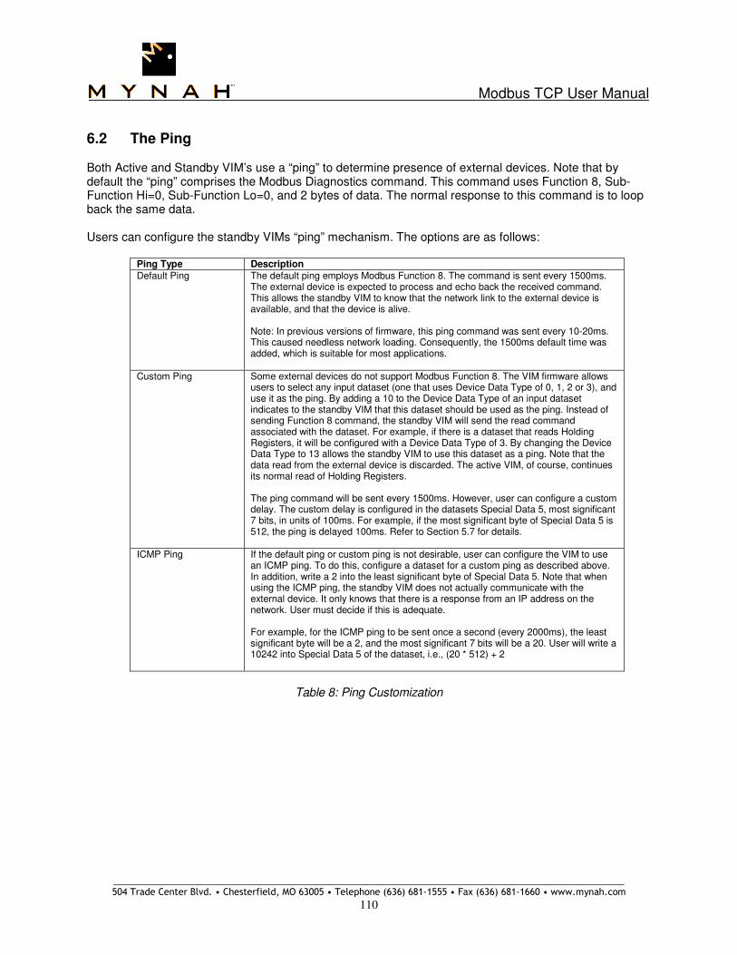
Modbus TCP User Manual
_____________________________________________________________________________________________________ 504 Trade Center Blvd. • Chesterfield, MO 63005 • Telephone (636) 681-1555 • Fax (636) 681-1660 • www.mynah.com
110
6.2 The Ping Both Active and Standby VIM’s use a “ping” to determine presence of external devices. Note that by default the “ping” comprises the Modbus Diagnostics command. This command uses Function 8, Sub-Function Hi=0, Sub-Function Lo=0, and 2 bytes of data. The normal response to this command is to loop back the same data. Users can configure the standby VIMs “ping” mechanism. The options are as follows:
Ping Type Description
Default Ping The default ping employs Modbus Function 8. The command is sent every 1500ms. The external device is expected to process and echo back the received command. This allows the standby VIM to know that the network link to the external device is available, and that the device is alive. Note: In previous versions of firmware, this ping command was sent every 10-20ms. This caused needless network loading. Consequently, the 1500ms default time was added, which is suitable for most applications.
Custom Ping Some external devices do not support Modbus Function 8. The VIM firmware allows users to select any input dataset (one that uses Device Data Type of 0, 1, 2 or 3), and use it as the ping. By adding a 10 to the Device Data Type of an input dataset indicates to the standby VIM that this dataset should be used as the ping. Instead of sending Function 8 command, the standby VIM will send the read command associated with the dataset. For example, if there is a dataset that reads Holding Registers, it will be configured with a Device Data Type of 3. By changing the Device Data Type to 13 allows the standby VIM to use this dataset as a ping. Note that the data read from the external device is discarded. The active VIM, of course, continues its normal read of Holding Registers. The ping command will be sent every 1500ms. However, user can configure a custom delay. The custom delay is configured in the datasets Special Data 5, most significant 7 bits, in units of 100ms. For example, if the most significant byte of Special Data 5 is 512, the ping is delayed 100ms. Refer to Section 5.7 for details.
ICMP Ping If the default ping or custom ping is not desirable, user can configure the VIM to use an ICMP ping. To do this, configure a dataset for a custom ping as described above. In addition, write a 2 into the least significant byte of Special Data 5. Note that when using the ICMP ping, the standby VIM does not actually communicate with the external device. It only knows that there is a response from an IP address on the network. User must decide if this is adequate. For example, for the ICMP ping to be sent once a second (every 2000ms), the least significant byte will be a 2, and the most significant 7 bits will be a 20. User will write a 10242 into Special Data 5 of the dataset, i.e., (20 * 512) + 2
Table 8: Ping Customization

Modbus TCP User Manual
_____________________________________________________________________________________________________ 504 Trade Center Blvd. • Chesterfield, MO 63005 • Telephone (636) 681-1555 • Fax (636) 681-1660 • www.mynah.com
111
6.3 Simplex External Device In this case the external device is non-redundant. It only has a single IP address available, but multiple network connections can be opened on this single IP address. Both the Active and Standby VIMs will communicate with the same IP address. Connect the external device to either one of the isolated switches. The Active VIM will perform actual data I/O communications. The standby VIM will send a periodic “ping” to the same IP address. The ping allows the standby VIM to ensure that the communication path is valid. If the standby VIM cannot verify network path validity, an error message will be generated back to DeltaV indicating Standby problems and switchover will not be available. If the standby path is valid, you can command VIM switchover using DeltaV Diagnostics. If the device IP address only allows one network connection, then the Standby VIM must use the network ICMP ping. This is described above in Section 6.2. Additionally, there are special considerations for devices which allow only one network connection, particularly in redundant mode. Refer to Special Data 5, Bit mask value 8 – One Connection Only, described above.
Figure 5: Redundant VIMs with Simplex Modbus Devices

Modbus TCP User Manual
_____________________________________________________________________________________________________ 504 Trade Center Blvd. • Chesterfield, MO 63005 • Telephone (636) 681-1555 • Fax (636) 681-1660 • www.mynah.com
112
6.4 Redundant External Device - Single Chassis with 2 NICs
In this case the external device has a single chassis but uses two network interface cards for communications with the VIMs. Connect each network card to a separate isolated switch corresponding to the VIM. The IP address of these network cards can be consecutive, e.g., 10.22.6.50 and 10.22.6.51. VIM A opens connections with both IP addresses 10.22.6.50 and 10.22.6.51. VIM B also opens connections with both IP addresses 10.22.6.50 and 10.22.6.51. The Active VIM communicates with the first IP address, while continuing to ping the second IP. The Standby VIM sends a periodic “ping” to its connected IP addresses. The ping allows the Standby VIM to ensure that the communication paths are valid. If the Standby VIM cannot verify network path validity, an error message will be generated back to DeltaV. The error message will indicate the Standby problems, and switchover will not be available. If the standby path is valid, you can command VIM switchover using DeltaV Diagnostics. If the Active VIM loses communications with the first IP address, it starts using the second IP address and does not request a switchover. Only if both IP address connections are lost will the Active VIM request a switchover. The DeltaV controller verifies that the switchover is possible and then commands the currently Active VIM to go Standby, and at the same time commands the currently Standby VIM to go Active. Both VIMs maintain current DeltaV outputs. On switchover, the new Active VIM immediately starts scanning the external inputs to update its internal database. The following illustrates the network for this level of redundancy:
Figure 6: Redundant VIMs with Redundant PLC Network Connections

Modbus TCP User Manual
_____________________________________________________________________________________________________ 504 Trade Center Blvd. • Chesterfield, MO 63005 • Telephone (636) 681-1555 • Fax (636) 681-1660 • www.mynah.com
113
The operational states in this level of redundancy are as follows: Scenario 1 Operating Conditions:
• VIM A is active
• VIM A is scanning 10.22.6.50 and Pinging 10.22.6.51
• VIM B is pinging 10.22.6.50 and 10.22.6.51
VIM A State VIM B State Redundancy State
Good Good VIM A stays active if 10.22.6.50 or 10.22.6.51 are good
Good Bad VIM A reports standby problems – switchover unavailable
Bad Good VIM A requests a switchover to VIM B if both 10.22.6.50 and 10.22.6.51 are bad, and VIM B reports these connections as good.
Table 9: Non-switching IP, VIM A Active
Scenario 2 Operating Conditions:
• VIM B is active
• VIM B is scanning 10.22.6.50 and Pinging 10.22.6.51
• VIM A is pinging 10.22.6.50 and 10.22.6.51
VIM A State VIM B State Redundancy State
Good Good VIM B stays active if 10.22.6.50 or 10.22.6.51 are good
Bad Good VIM B reports standby problems – switchover unavailable
Good Bad VIM B requests a switchover to VIM A if both 10.22.6.50 and 10.22.6.51 are bad, and VIM A reports these connections as good.
Table 10: Non-switching IP, VIM B Active

Modbus TCP User Manual
_____________________________________________________________________________________________________ 504 Trade Center Blvd. • Chesterfield, MO 63005 • Telephone (636) 681-1555 • Fax (636) 681-1660 • www.mynah.com
114
6.5 Redundant External Device – 2 HSBY Chassis with 1 NIC Each In this case the external device has two chassis that behave as a redundant pair. There is one network card in each chassis for communications with the VIMs. Connect each network card to a separate isolated switch corresponding to the VIM. The IP address of these network cards can be consecutive, e.g., 10.22.6.50 and 10.22.6.51. It is expected that the IP address will switch between both chassis when a chassis switchover occurs. For example, if 10.22.6.50 is used, it will always be the ACTIVE IP address regardless of which chassis is active. This is also known as Hot Standby (HSBY). The Active VIM communicates with the IP address in the Active chassis. This is expected to be the first IP address. The Standby VIM sends a periodic “ping” to the IP address in the Standby chassis (second IP address). The ping allows the standby VIM to ensure that the communication path is valid. If the standby VIM cannot verify network path validity, an error message will be generated back to DeltaV indicating Standby problems and switchover will not be available. If the standby path is valid, you can command VIM switchover using DeltaV Diagnostics. Note that the “ping” comprises the Modbus Diagnostics loopback data command. If the Active VIM loses communications and the Standby path is valid, the VIM will automatically request a switchover to its partner. The DeltaV controller verifies that the switchover is possible and then commands the currently Active VIM to go Standby, and at the same time commands the currently Standby VIM to go Active. Both VIMs maintain current DeltaV outputs. On switchover, the new Active VIM immediately starts scanning the external inputs to update its internal database. If the external device chassis switches from Active to Standby, it will assume the IP address of the previous Standby. Simultaneously, the current Active will assume the IP address of the previous Active. Note that this switchover will not result in VIM switchover. This is because the VIM is still communicating with the same Active IP. The VIM will switch only if it loses communications with the Active chassis and the standby path is valid.
Figure 7: Redundant VIMs with PLC configured as Hot Backup, 2 NICs

Modbus TCP User Manual
_____________________________________________________________________________________________________ 504 Trade Center Blvd. • Chesterfield, MO 63005 • Telephone (636) 681-1555 • Fax (636) 681-1660 • www.mynah.com
115
The operational states in this level of redundancy are as follows: Scenario 1 Operating Conditions:
• VIM A is active
• VIM A is scanning 10.22.6.50
• VIM B is pinging 10.22.6.51
VIM A State VIM B State Redundancy State
Good Good VIM A stays active
Good Bad VIM A reports standby problems – switchover unavailable
Bad Good VIM A requests a switchover to VIM B
Table 11: Switching IP, VIM A Active
Scenario 2 Operating Conditions:
• VIM B is active
• VIM B is scanning 10.22.6.50
• VIM A is pinging 10.22.6.51
VIM A State VIM B State Redundancy State
Good Good VIM B stays active
Bad Good VIM B reports standby problems – switchover unavailable
Good Bad VIM B requests a switchover to VIM A
Table 12: Switching IP, VIM B Active

Modbus TCP User Manual
_____________________________________________________________________________________________________ 504 Trade Center Blvd. • Chesterfield, MO 63005 • Telephone (636) 681-1555 • Fax (636) 681-1660 • www.mynah.com
116
6.6 Redundant External Device – 2 HSBY Chassis with 2 NICs Each In this option, each chassis contains two NIC’s. The assigned IP addresses are IP and IP+2 for NIC’s in primary chassis, while the secondary chassis uses IP+1 and IP+3. In both options, the IP addresses assigned to the NIC’s are fixed based on which chassis is Primary. When chassis role switchover occurs, IP addresses also switch and the new primary chassis resumes with IP and IP+2, and the new secondary resumes with IP+1 and IP+3. Schneider Quantum PLC’s is an example of this option. It is important to note that as a factory default, the chassis switchover occurs only on loss of the primary chassis, e.g., loss of CPU or chassis power. Loss of network communications does not cause chassis switchover. Users must add special logic to the PLC to monitor the NIC’s and initiate chassis switchover on loss of communications. For the single NIC option, the logic must initiate switchover when communications are lost on the primary NIC. For the double NIC option, the logic must initiate chassis switchover on loss of communications on both NIC’s.
Figure 8: Redundant VIMs with PLC configured as Hot Backup, 4 NICs

Modbus TCP User Manual
_____________________________________________________________________________________________________ 504 Trade Center Blvd. • Chesterfield, MO 63005 • Telephone (636) 681-1555 • Fax (636) 681-1660 • www.mynah.com
117
The Active VIM opens connections with the primary chassis NIC addresses, IP and IP+2. The Standby VIM also opens connections with the secondary chassis NIC addresses, IP+1 and IP+3. The Active VIM communicates with the first IP address, while continuing to ping the second IP. The Standby VIM sends a periodic “ping” to its connected IP addresses. The ping allows the Standby VIM to ensure that the communication paths are valid. If the Standby VIM cannot verify network path validity, an error message is generated and sent to DeltaV Diagnostics. The error message is displayed in the standby serial cards dataset level. The active and standby serial cards, card level, will both indicate the standby problems, and switchover will not be available. All errors are cleared if the standby paths are valid. If the Active VIM loses communications with the first connected IP address, it immediately starts using the second IP address and does not request a switchover. Only if both IP address connections are lost will the Active VIM request a switchover. The DeltaV controller verifies that the switchover is possible and then commands the currently Active VIM to go Standby, and at the same time commands the currently Standby VIM to go Active. Both VIMs maintain current DeltaV outputs. On switchover, the new Active VIM immediately starts scanning the field inputs to update its internal database. On loss of communications or loss of the physical, electrical cable connections on both NIC’s Ethernet ports, it is expected that the primary PLC chassis will perform a switchover. If the PLC chassis switchover occurs, the Active VIM may or may not switch. This depends on whether a loss of communication is detected while the chassis switchover is in progress. If a VIM switchover is required, communications will resume after a successful connection with the primary chassis addresses, IP or IP+2 is established.

Modbus TCP User Manual
_____________________________________________________________________________________________________ 504 Trade Center Blvd. • Chesterfield, MO 63005 • Telephone (636) 681-1555 • Fax (636) 681-1660 • www.mynah.com
118
6.7 User Application Initiated Redundant Switchover As described above, under normal operations, the Active VIM scans the primary IP address, while the Standby VIM “pings” the backup IP address. If the Active VIM loses communications and the Standby path is valid, the VIM will automatically request a switchover to its partner. This request for switchover is sent to the DeltaV controller. The DeltaV controller verifies that the switchover is possible. Then, it commands the currently Active VIM to go Standby and commands the currently Standby VIM to go Active. Consequently, the redundancy switchover is strictly driven by external communications. In some cases, it is desirable to allow the user application to force a VIM switchover. This firmware supports this capability by using the VIM Diagnostics dataset. Please see Section 5.4 on how to configure the Diagnostics dataset, which can also be used for the switchover command. If the VIM Diagnostics dataset is configured as Output with Output read back, all VIM Diagnostics will be sent up normally. In addition, a DeltaV Control Module can be configured to write a value (any value) to any register in this dataset. The VIM will interpret this write command as a user-triggered request for switchover and take the appropriate action. As in the normal operating case, the request will be sent to the DeltaV controller, and the controller will initiate the switch.

Modbus TCP User Manual
_____________________________________________________________________________________________________ 504 Trade Center Blvd. • Chesterfield, MO 63005 • Telephone (636) 681-1555 • Fax (636) 681-1660 • www.mynah.com
119
6.8 Hot Replacement of faulty Redundant VIM During normal operation, a redundant VIM pair is in continuous communication with each other. This link is achieved over the network using an interconnecting cable between two switches as shown below in red.
Figure 9: Redundant VIM Network This link is crucial to the health of the redundant VIM network. Without it, each VIM is blind to its partner’s state. If there is a VIM failure, the redundant partner will detect that there is a standby problem. Furthermore, this network link is used by the Active VIM to commission and configure a replacement VIM as described below. If a VIM fails, the DeltaV Controller will immediately send a Go Active command to the partner VIM. The dead VIM will appear in one or more of the following ways:
1. The red Fault LED will be ON. The state of other LEDs is not significant if the fault LED is on. 2. The emulated serial cards will not be present in DeltaV Diagnostics. All Odd or Even number
cards will appear as Configured but not present, depending on which VIM failed. By convention, VIM A handles all odd cards, and VIM B handles all even cards.
3. The active VIM will show that the standby is not communicating, and rebooting the dead VIM
does not clear the problem.
4. One or more of the 4 tickers displayed in the VIMNet Diagnostics application are not counting, even after restarting the diagnostics application.

Modbus TCP User Manual
_____________________________________________________________________________________________________ 504 Trade Center Blvd. • Chesterfield, MO 63005 • Telephone (636) 681-1555 • Fax (636) 681-1660 • www.mynah.com
120
In these cases, the redundant VIM firmware allows for automated recovery from failed VIM hardware. The steps to recover are as follows:
1. Replace the dead VIM with a decommissioned VIM. The replacement VIM must already be flashed to the same firmware revision number and application type.
Never replace a dead VIM with an already commissioned VIM. The replacement must be decommissioned. Furthermore, the replacement VIM must be of the same firmware revision and application type. Failure to follow these rules will cause disruption in external communications and on the Railbus. For assistance or more information regarding these rules, please contact Mynah Technical Support.
2. Verify that the VIM network inter-communication link is in place.
3. Confirm that there is going to be only one decommissioned VIM on this sub-net. If the Active VIM
detects more than one decommissioned VIM, the auto recovery will be aborted. The Active VIM will reset its list of detected VIMs and restart the detection process.
4. If during a 30-40 second period, one and only one decommissioned VIM is detected that matches
the revision number and application type, the Active VIM will send a commissioning command to it. The IP address used will be the same as the removed dead VIM.
5. After the commissioning command is processed by the new VIM, it will reboot. After reboot,
normal communications will begin between the redundant pair. The new VIM will report to the Active VIM that it does not have any configuration. The Active VIM will then upload the network devices configuration to the new VIM, after which the new VIM will reboot again. The new VIM will restart and now will be completely online, but in the Standby state. This entire process will complete in approximately one minute.
After the new VIM is online and operational, it will appear in the VIMNet Explorer as a mismatched device under the Decommissioned list. Furthermore, the placeholder will have an error asserted as shown below:

Modbus TCP User Manual
_____________________________________________________________________________________________________ 504 Trade Center Blvd. • Chesterfield, MO 63005 • Telephone (636) 681-1555 • Fax (636) 681-1660 • www.mynah.com
121
The following steps must be performed to reconcile the VIMNet configuration with the online network device states:
1. Right click on the VIM placeholder and decommission the VIM that was removed. This will clear the red X and clear the placeholder.
2. Right click on the VIM placeholder and select Reconcile VIM. Then select the VIM from the presented list. The selected VIM will be assigned to the empty placeholder.

Modbus TCP User Manual
_____________________________________________________________________________________________________ 504 Trade Center Blvd. • Chesterfield, MO 63005 • Telephone (636) 681-1555 • Fax (636) 681-1660 • www.mynah.com
122
7.0 Operational Check 7.1 Scope The following sections provide some assistance to ensure the interface is working properly.
7.2 Verify Hardware and Software Version Number You can verify that the Modbus TCP driver has been installed using the DeltaV Diagnostics tool. The Diagnostics tool will show the Hardware Revision No. (HwRev) and the Software Revision No. (SwRev). To begin the DeltaV Diagnostic tool select Start-> DeltaV-> Operator-> Diagnostics. In the Diagnostics tool, expand the Controller, I/O, and then double click on the Programmable Serial Interface Card that has the driver installed. The following information will be displayed:
HwRev Hardware Revision 1.1 or later SwRev Software Revision 3.8 or later
Table 13: Verifying Hardware and Software Version Numbers
7.3 Verify Configuring Verify the port configuration. The serial port must be enabled. Verify dataset configuration: The datasets configured must be as shown above.
7.4 Verify I/O Communication with Control Studio You can create I/O modules in the control studio to verify correct values are read from the VIM. For AI and DI data, the values should be changed in the external devices and verified that the new data are correctly reported in DeltaV. Similarly, verify that the AO and DO data is being written correctly from DeltaV to the external devices.
7.5 Using DeltaV Diagnostics Verify VIM communication: Select the emulated PSIC in Diagnostics and press the right mouse button. Select Display Real -Time Statistics from the drop down menu. If the PSIC is functioning, then you will see the Valid Responses counter and the Async and/or Sync Transactions counters incrementing. There will not be any errors counting up. Verify port statistics: Select the Port on the emulated PSIC and press the right mouse button. Then select Display Port Statistics from the drop down menu. Verify that the port communications statistics are being displayed properly and are counting as expected for the protocol’s functionality. Verify dataset values: Select a dataset and press the right mouse button. Select View Dataset Registers from the Drop down window. Verify that the dataset values are displayed as expected. The DeltaV diagnostics and port level statistics show VIM internal memory and loading information.

Modbus TCP User Manual
_____________________________________________________________________________________________________ 504 Trade Center Blvd. • Chesterfield, MO 63005 • Telephone (636) 681-1555 • Fax (636) 681-1660 • www.mynah.com
123
7.6 LED Indication The VIM has six LEDs in front. Top to bottom, these are as follows:
Green Power Red Fault
Green Active
Green Standby
Amber Network Communications
Amber Railbus Communications
Table 14: LED Indication
The following table describes the VIM operational state as indicated by the LEDs: LED State Description Green Red Green Green Amber Amber
ON OFF OFF OFF Blink Off
The VIM is Decommissioned. It does not have an assigned IP address. Use the VIMNet Explorer to configure a VIM placeholder. The VIM placeholder contains the IP address for your network. Then commission the VIM as described in Section 3.
Green Red Green Green Amber Amber
ON OFF ON OFF Blink OFF
The VIM is Commissioned. It is not communicating on the Railbus. Verify that the DeltaV controller has been downloaded. Also, verify that the external device configuration has been uploaded into the VIM from the VIMNet Explorer.
Green Red Green Green Amber Amber
ON OFF ON OFF ON ON
The VIM is Commissioned, and communicating with the external devices, as well as with the DeltaV controller.
Green Red Green Green Amber Amber
ON OFF ON OFF Blink ON
The VIM is Commissioned, and communicating with the DeltaV controller. The external device communications have errors.
Green Red Green Green Amber Amber
ON OFF ON OFF Blink OFF
The VIM is Commissioned, but communications with the DeltaV controller are not active. The external device communications have errors.
Green Red Green Green Amber Amber
ON ON X X X X
The VIM is in fault. All other LED states (marked with X) are not significant.
Table 15: Simplex VIM LED State Specifications

Modbus TCP User Manual
_____________________________________________________________________________________________________ 504 Trade Center Blvd. • Chesterfield, MO 63005 • Telephone (636) 681-1555 • Fax (636) 681-1660 • www.mynah.com
124
LED State Description Green Red Green Green Amber Amber
ON OFF OFF OFF Blink Off
The VIM is Decommissioned. It does not have an assigned IP address. Use the VIMNet Explorer to configure a VIM placeholder. The VIM placeholder contains the IP address for your network. Then commission the VIM as described in Section 3.
Green Red Green Green Amber Amber
ON OFF ON OFF Blink OFF
The VIM is Commissioned. The current redundancy role is ACTIVE. It is not communicating on the Railbus. Verify that the DeltaV controller has been downloaded. Also, verify that the external device configuration has been uploaded into the VIM from the VIMNet Explorer.
Green Red Green Green Amber Amber
ON OFF OFF ON Blink OFF
The VIM is Commissioned. The current redundancy role is STANDBY. It is not communicating on the Railbus. Verify that the DeltaV controller has been downloaded. Also, verify that the external device configuration has been uploaded into the VIM from the VIMNet Explorer.
Green Red Green Green Amber Amber
ON OFF ON OFF ON ON
The VIM is Commissioned, and communicating with the external devices, as well as with the DeltaV controller. The current redundancy role is ACTIVE. Note that if the Active LED is OFF and the Standby LED is ON, the current role is Standby.
Green Red Green Green Amber Amber
ON OFF ON OFF Blink ON
The VIM is Commissioned, and communicating with the DeltaV controller. The external device communications have errors. The current redundancy role is ACTIVE. Note that if the Active LED is OFF and the Standby LED is ON, the current role is Standby.
Green Red Green Green Amber Amber
ON OFF ON OFF Blink OFF
The VIM is Commissioned, but communications with the DeltaV controller are not active. The external device communications have errors. The current redundancy role is ACTIVE. Note that if the Active LED is OFF and the Standby LED is ON, the current role is Standby.
Green Red Green Green Amber Amber
ON ON X X X X
The VIM is in fault. All other LED states (marked with X) are not significant.
Table 16: Redundant VIM LED State Specifications

Modbus TCP User Manual
_____________________________________________________________________________________________________ 504 Trade Center Blvd. • Chesterfield, MO 63005 • Telephone (636) 681-1555 • Fax (636) 681-1660 • www.mynah.com
125
8.0 Technical Support For technical support or to report a defect, please give MYNAH Technologies a call at (636) 681-1555. If a defect is discovered, please document it in as much detail as possible and then fax your report to us at (636) 681-1660. You can also send us your questions via e-mail. Our address is:

Modbus TCP User Manual
_____________________________________________________________________________________________________ 504 Trade Center Blvd. • Chesterfield, MO 63005 • Telephone (636) 681-1555 • Fax (636) 681-1660 • www.mynah.com
126
9.0 Example Use Cases The following example use cases are described: PLC System Description
Schneider Quantum PLC HSBY – 2 NICs Uses 140 NOE 771-11 cards
Schnedier Quantum HSBY – 4 NICs Uses 140 NOE 771-11 cards
Invensys Triconex Uses TCM 4351B or 4352A cards
Bently Nevada Uses the 3500/92 Communication card
ControlLogix Uses the ProSoft Modbus TCP card
Emerson S600 Flow Computer Two network cards
9.1 Schneider Quantum PLC HSBY – 2 NICs The architecture is as follows. Each chassis contains one NIC (140 NOE 771-11) card:
The PLC configuration provides IP address switching. Specifically, a single IP address is configured in the NOE card. The Primary chassis uses this IP address, while the Standby chassis uses IP+1. Special Quantum function blocks are configured into the PLC to trigger chassis switchover based on loss of communications on the Primary chassis IP address. The active VIM always connects to the configured IP for communication, while the backup VIM connects to IP+1. Configure the external device in the VIMNet Explorer as follows:

Modbus TCP User Manual
_____________________________________________________________________________________________________ 504 Trade Center Blvd. • Chesterfield, MO 63005 • Telephone (636) 681-1555 • Fax (636) 681-1660 • www.mynah.com
127

Modbus TCP User Manual
_____________________________________________________________________________________________________ 504 Trade Center Blvd. • Chesterfield, MO 63005 • Telephone (636) 681-1555 • Fax (636) 681-1660 • www.mynah.com
128
9.2 Schneider Quantum PLC HSBY – 4 NICs
The architecture is as follows. Each chassis contains two NIC (140 NOE 771-11) cards:
The PLC configuration provides IP address switching. The Primary chassis uses IP address for first card and IP+2 on the second card, while the Standby chassis uses IP+1 on the first card and IP+3 on the second. Special Quantum function blocks are configured into the PLC to trigger chassis switchover based on loss of communications on both cards of Primary chassis. The VIM is configured with no IP-Switching connectivity. The active VIM always connects to the configured IP, and IP+2 for communications.
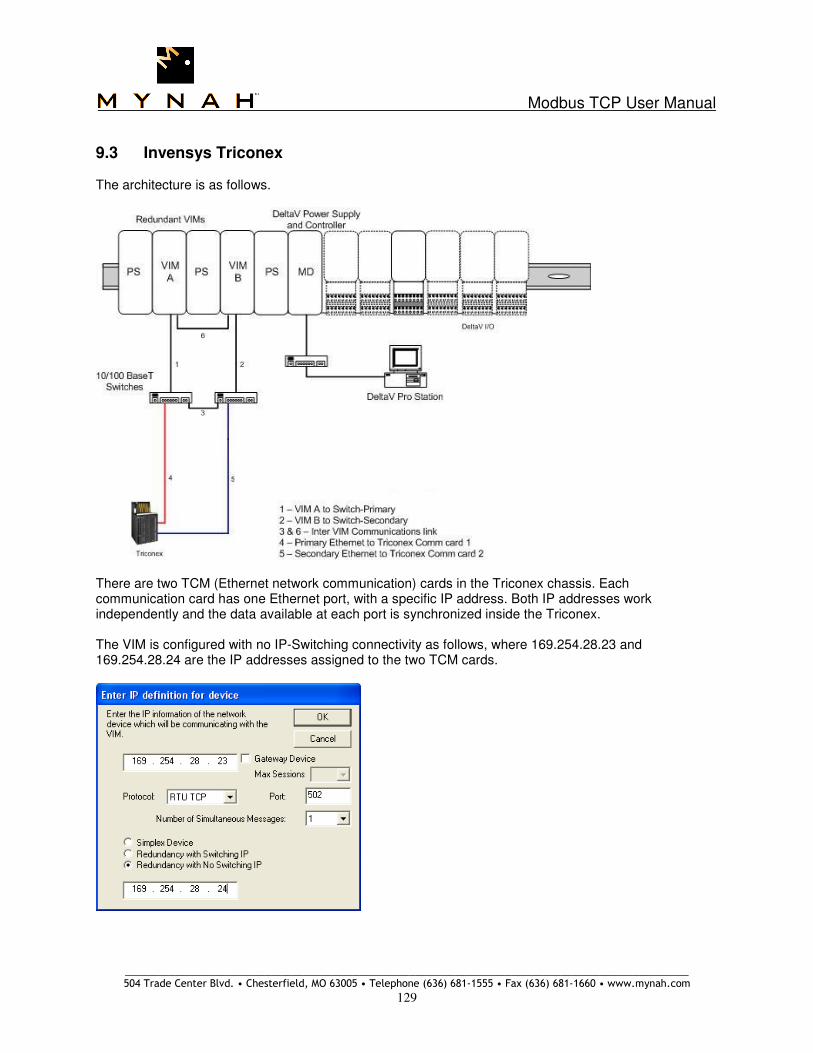
Modbus TCP User Manual
_____________________________________________________________________________________________________ 504 Trade Center Blvd. • Chesterfield, MO 63005 • Telephone (636) 681-1555 • Fax (636) 681-1660 • www.mynah.com
129
9.3 Invensys Triconex
The architecture is as follows.
There are two TCM (Ethernet network communication) cards in the Triconex chassis. Each communication card has one Ethernet port, with a specific IP address. Both IP addresses work independently and the data available at each port is synchronized inside the Triconex.
The VIM is configured with no IP-Switching connectivity as follows, where 169.254.28.23 and 169.254.28.24 are the IP addresses assigned to the two TCM cards.

Modbus TCP User Manual
_____________________________________________________________________________________________________ 504 Trade Center Blvd. • Chesterfield, MO 63005 • Telephone (636) 681-1555 • Fax (636) 681-1660 • www.mynah.com
130
For communication effectiveness, configure the TCM as follows. The TCM cards are configured via the TriStation application.
Click on the TCM module to display its properties.

Modbus TCP User Manual
_____________________________________________________________________________________________________ 504 Trade Center Blvd. • Chesterfield, MO 63005 • Telephone (636) 681-1555 • Fax (636) 681-1660 • www.mynah.com
131
On the Network tab select 10 Mbps Half Duplex or Auto-Negotiate for both Left and Right TCM cards. Note that the VIM’s communicate at 10Mbps Half Duplex. Alternatively, an Auto-Negotiate switch can be used between the VIM’s and the TCM network ports. Specify the IP address for both Left and Right TCM cards. In the following display, we are using NET 1 for VIM communications.

Modbus TCP User Manual
_____________________________________________________________________________________________________ 504 Trade Center Blvd. • Chesterfield, MO 63005 • Telephone (636) 681-1555 • Fax (636) 681-1660 • www.mynah.com
132
Select the Modbus TCP tab and configure the Port Selection and Port Settings as shown below. In the Port Selection list, 16 ports can be configured. It is recommended that all 16 ports be configured. For each Port number, specify the IP address of the VIM as shown in the Port Settings group below. Configure the first 8 Port numbers (1-8) for VIM-A, and the remaining 8 Port numbers (9-16) for VIM-B. By specifying an IP address, only the VIM with the given IP address will be able to communicate with this TCM port. Either configure this field with blanks, which means any external master can connect to the TCM. Or alternatively, configure ports 1-8 with the IP address of VIM-A, and ports 9-16 with the IP address of VIM-B. In the screenshot below, the 169.254.28.3 is the IP address of VIM-A. Configuring multiple ports is a VIM requirement. As described above, VIMs open multiple network connections with each TCM. With 8 ports configured with the IP address of VIM-A, and 8 ports configured with IP address of VIM-B, both VIMs will be able to communicate with each TCM card as required in a redundant setup. Lastly, duplicate this configuration for Right TCM card. Both Left and Right TCM cards must have the same configuration.

Modbus TCP User Manual
_____________________________________________________________________________________________________ 504 Trade Center Blvd. • Chesterfield, MO 63005 • Telephone (636) 681-1555 • Fax (636) 681-1660 • www.mynah.com
133
9.4 Bently Nevada
The architecture is as follows.
There are two Ethernet network communication cards in each Bently-Nevada chassis. Each communication card has one Ethernet port, with a specific IP address. Both IP addresses work independently and the data available at each port is synchronized inside the Bently-Nevada. The VIM is configured with no IP-Switching connectivity as follows, where 10.22.6.10 and 10.22.6.11 are the IP addresses assigned to the two Bently Nevada communication cards.
Note that the Bently-Nevada PLC does not support Modbus Function 8. Consequently, an alternate ping mechanism must be selected and used as described in Section 6.2.

Modbus TCP User Manual
_____________________________________________________________________________________________________ 504 Trade Center Blvd. • Chesterfield, MO 63005 • Telephone (636) 681-1555 • Fax (636) 681-1660 • www.mynah.com
134
9.5 ControlLogix via ProSoft Card
The Rockwell ControlLogix connectivity architecture is as follows:
There are two ProSoft ModbusTCP network communication cards in the ControlLogix chassis. Each communication card has one Ethernet port, with a specific IP address. Both IP addresses work independently and the data available at each port is synchronized inside the ControlLogix. The VIM is configured with no IP-Switching connectivity as follows, where 10.22.6.10 and 10.22.6.11 are the IP addresses assigned to the two ProSoft cards.
Note that user must configure data block transfers in the ControlLogix ladder logic to move data to/from the ProSoft communications cards.

Modbus TCP User Manual
_____________________________________________________________________________________________________ 504 Trade Center Blvd. • Chesterfield, MO 63005 • Telephone (636) 681-1555 • Fax (636) 681-1660 • www.mynah.com
135
9.6 Emerson S600 Flow Computer
The architecture for redundant FloBoss S600 is as follows:
The Configuration for Redundant FloBoss S600
It is important to note that FloBoss S600 requires both network interfaces to be configured with different subnets and use different port numbers. For example, S600 network A can be configured with IP address 10.12.1.100 and subnet mask 255.255.255.0., while S600 network B must be configured with IP address such as 10.12.2.100 and same subnet mask. Furthermore, the port numbers for Network A and Network B must be unique.
However, the VIM architecture requires that both S600 network interfaces be simultaneously available on a single network. For this reason, the subnet mask is changed to 255.255.0.0. Using this subnet mask, the VIMs can connect to both Network A and Network B. For compatibility with VIM configuration, the port numbers must be consecutive and the special data 5 flags used to designate this fact.
In the VIMNet Explorer, configure a redundant device with IP addresses as specified above and set the redundancy type to “Redundancy with No IP Switching”. The port number must be configured to the lowest of two configured in the FloBoss.

Modbus TCP User Manual
_____________________________________________________________________________________________________ 504 Trade Center Blvd. • Chesterfield, MO 63005 • Telephone (636) 681-1555 • Fax (636) 681-1660 • www.mynah.com
136
The VIM cards must be configured similarly with IP addresses and subnet mask 255.255.0.0. For example, VIM A is configured with IP address 10.12.1.1, while VIM B is configured with IP address 10.12.2.1. The subnet mask is set to 255.255.0.0 as shown below.

Modbus TCP User Manual
_____________________________________________________________________________________________________ 504 Trade Center Blvd. • Chesterfield, MO 63005 • Telephone (636) 681-1555 • Fax (636) 681-1660 • www.mynah.com
137
Configure Special Data 5 of the first dataset with the following two flags.
The first flag is a value 128, which allows the Active VIM A to connect to S600 Network A IP address and its port only. In our example, the VIM A would connect to IP address 10.12.1.100 and port number 501. The Standby VIM B would connect to remaining IP address 10.12.2.100 and port + 1 = 502.
The second flag is a value of 256, which allows the Active VIM A to connect to S600 Network A only, while the Standby VIM B connects to S600 Network B only.