isolated 8 channel analog input modbus tcp module … · there are 3 protocols we support that...
TRANSCRIPT
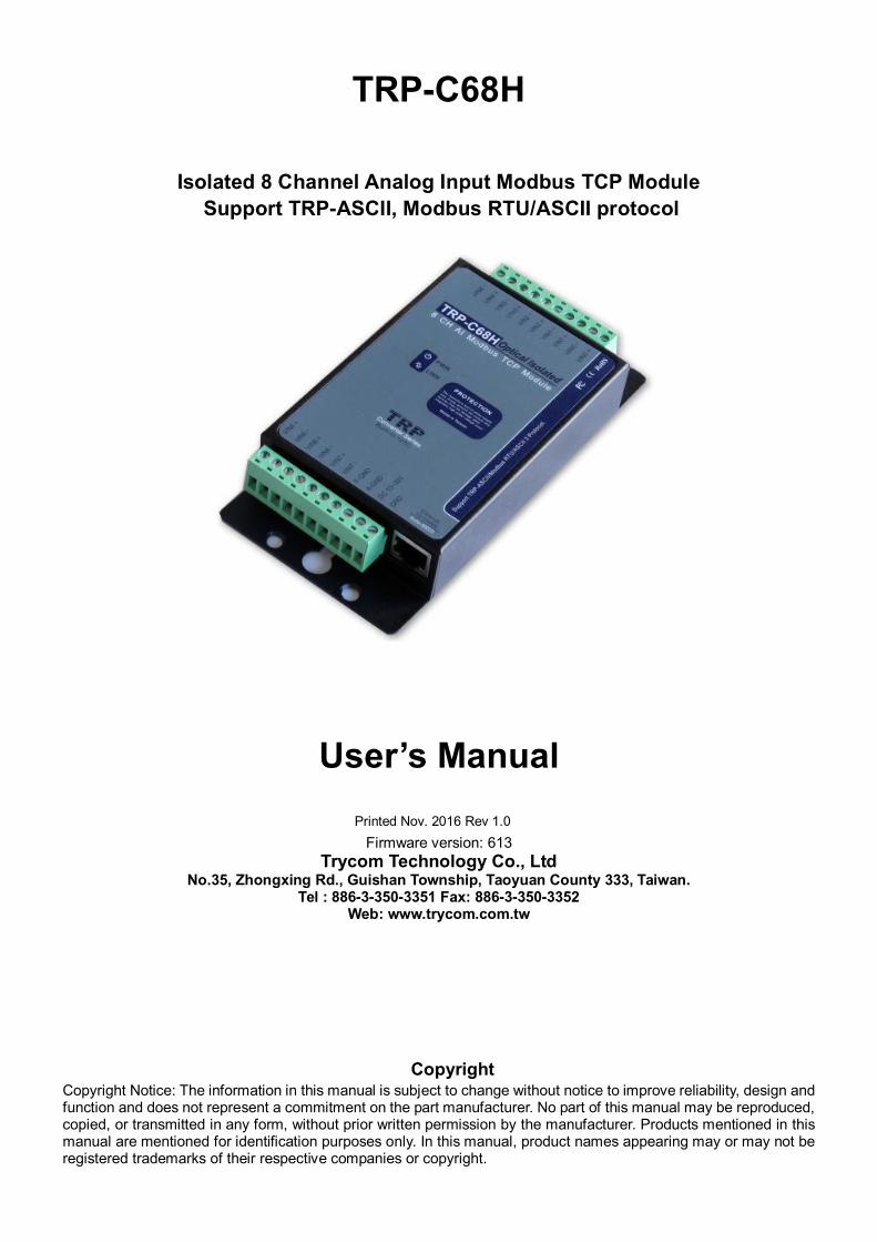
TRP-C68H
Isolated 8 Channel Analog Input Modbus TCP Module Support TRP-ASCII, Modbus RTU/ASCII protocol
User’s Manual
Printed Nov. 2016 Rev 1.0 Firmware version: 613
Trycom Technology Co., Ltd No.35, Zhongxing Rd., Guishan Township, Taoyuan County 333, Taiwan.
Tel : 886-3-350-3351 Fax: 886-3-350-3352 Web: www.trycom.com.tw
Copyright Copyright Notice: The information in this manual is subject to change without notice to improve reliability, design and function and does not represent a commitment on the part manufacturer. No part of this manual may be reproduced, copied, or transmitted in any form, without prior written permission by the manufacturer. Products mentioned in this manual are mentioned for identification purposes only. In this manual, product names appearing may or may not be registered trademarks of their respective companies or copyright.
2
1. Introduction The TRP-C68H is an 8-ch analog Input differential isolation module that can read the voltage or current
value from the web-based.
Each channel allows the user to input the voltage value or current.
We built-in safety surge protection prevents the spark and damage analog chipsets at each channel.
There are 3 protocols we support that include ASCII and Modbus TCP RTU / ASCII.
The watchdog function ensures running stable under harsh environment.
It allows connecting 1~8 sets of host IP in the network security.
1-1 .Features
Wide input range DC power supply. Automatically determine 3 TRP-ASCII and Modbus RTU/ASCII communication protocol. 16 TCP Port can be open at the same time. Heart Beat function ensures a reliable communicating connection. Maximum 8 sets host IP that limits network access. Support Virtual-COM mode. The web-based can be directly read analog value status. It is easy to update the firmware by LAN interface. Back to factory configuration by external touch button. Auto reconnection when power or Ethernet fail. Digital input signal from +/- 0 to 30V DC. Built-in surge absorbers in each relay N.C and N.O. Built-In watchdog function prevents system boot fail. LED for each I/O channels working status. Support Auto-MDIX twisted pair crossover detection and Auto-Correction. Power/Link LED indicator. DIN-Rail and panel mount support. Dual power input selects from screw terminal or DC-Jack.
1-2 .Specification
Resolution: 16 bit/24bit. Sample rate: 24 BIT Normal mode: 10 sample / sec.
16 BIT Fast Mode: 60 sample / sec.
Bandwidth: Normal Mode: 15.72Hz.
Fast Mode:/78.72Hz.
Zero drift: 0.03uV/C .
Span drift: 25 ppm/C.
Accuracy: Normal 0.1 or better.
Fast: 0.5 or better.
Analog Input range: Voltage:±10V,±5V,±2.5V,±1.25V,±650mV..
Current: +/-20mA. CMRR:92 db min/50/60Hz
3
Analog input over voltage protection: +/- 48V. Power Input Voltage DC +10V to +30V. Protocol: TRP-ASCII and Modbus RTU/ASCII.
Input channel:8-ch analog Input differential
Input optical isolation: 3750 Vrms. Communication interface: Ethernet RJ45. Configuration mode: Device Manager, WEB settings. Heart Beat: TCP Port sent string every 5 seconds. TCP Maximum Connection:1~16. Module ID: 1~255. Connection type: Screw terminal for maximum AWG 12 wire. Power supply: Screw terminal, or external DC adapter. Power consumption 320mA/12V. Operating environment: 0 to 50℃. Storage temperature: -10 to 70℃. Humidity: 10~90% Non-condensing. Dimension: 151mm X 75mm X 26mm. Weight: 395g.
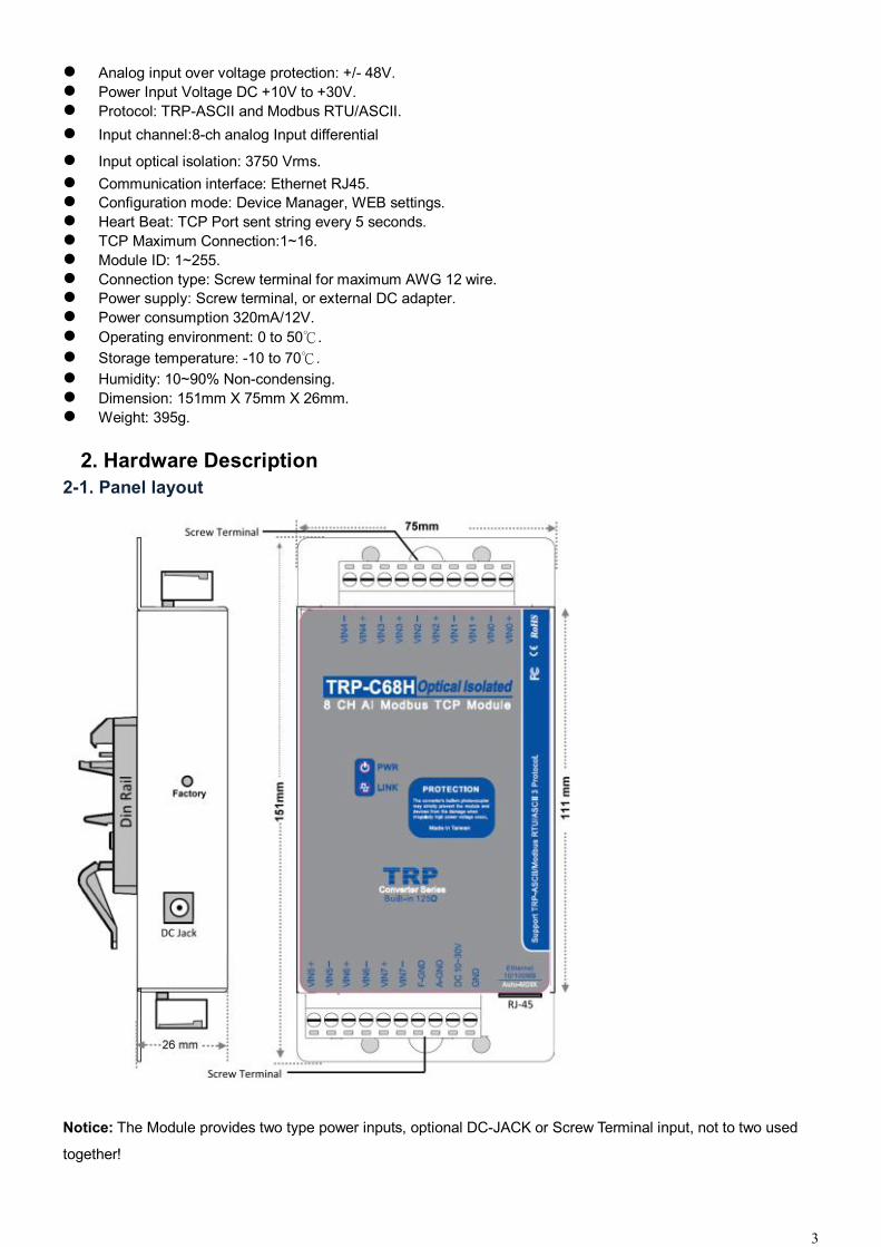
2. Hardware Description 2-1. Panel layout
Notice: The Module provides two type power inputs, optional DC-JACK or Screw Terminal input, not to two used
together!
4
PWR LED: Blinking is ready.
LINK LED: RJ-45 cable connection and data active.
DC Jack: Power Input DC +10V to +30V, Please use the 5.5*2.1mm DC JACK.
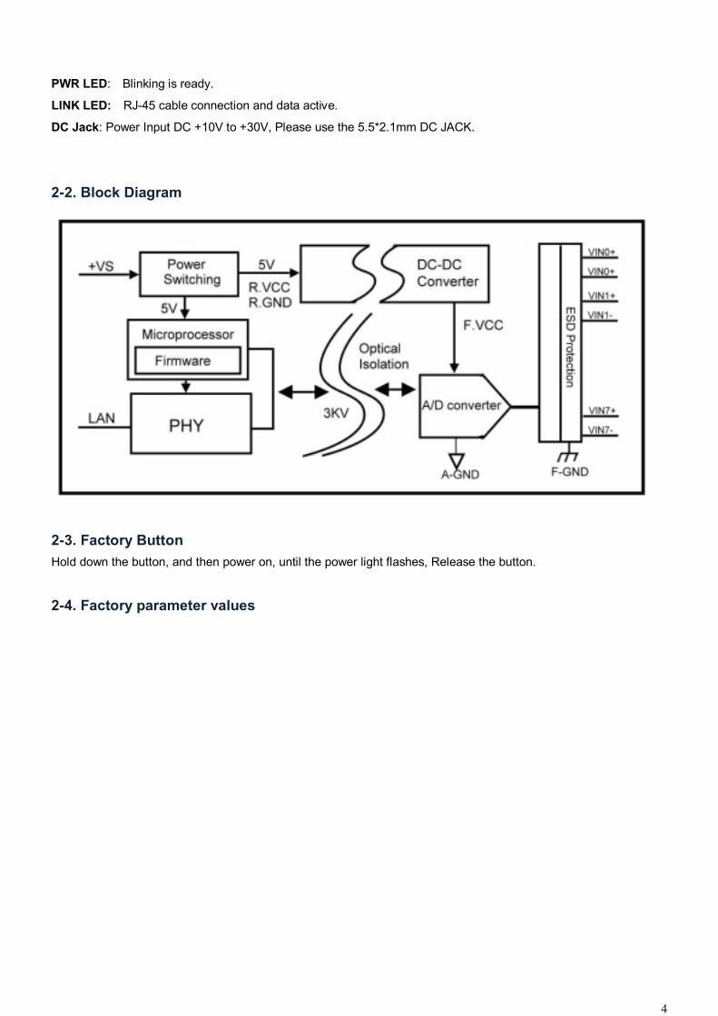
2-2. Block Diagram
2-3. Factory Button Hold down the button, and then power on, until the power light flashes, Release the button.
2-4. Factory parameter values
5
6
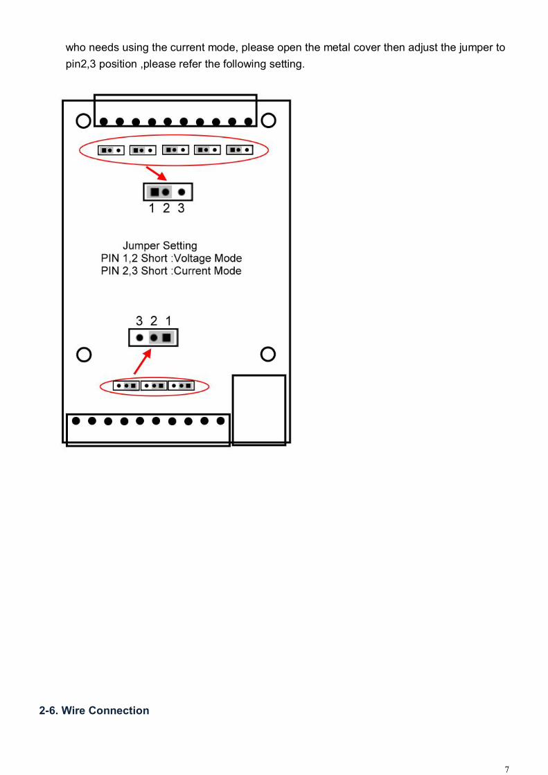
2-5. Voltage and current selectable. The TRP-C68H which is built in 125ohm resistors inside. The default is for voltage mode, if user
7
who needs using the current mode, please open the metal cover then adjust the jumper to pin2,3 position ,please refer the following setting.
2-6. Wire Connection
8
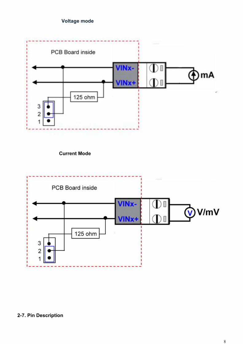
Voltage mode
Current Mode
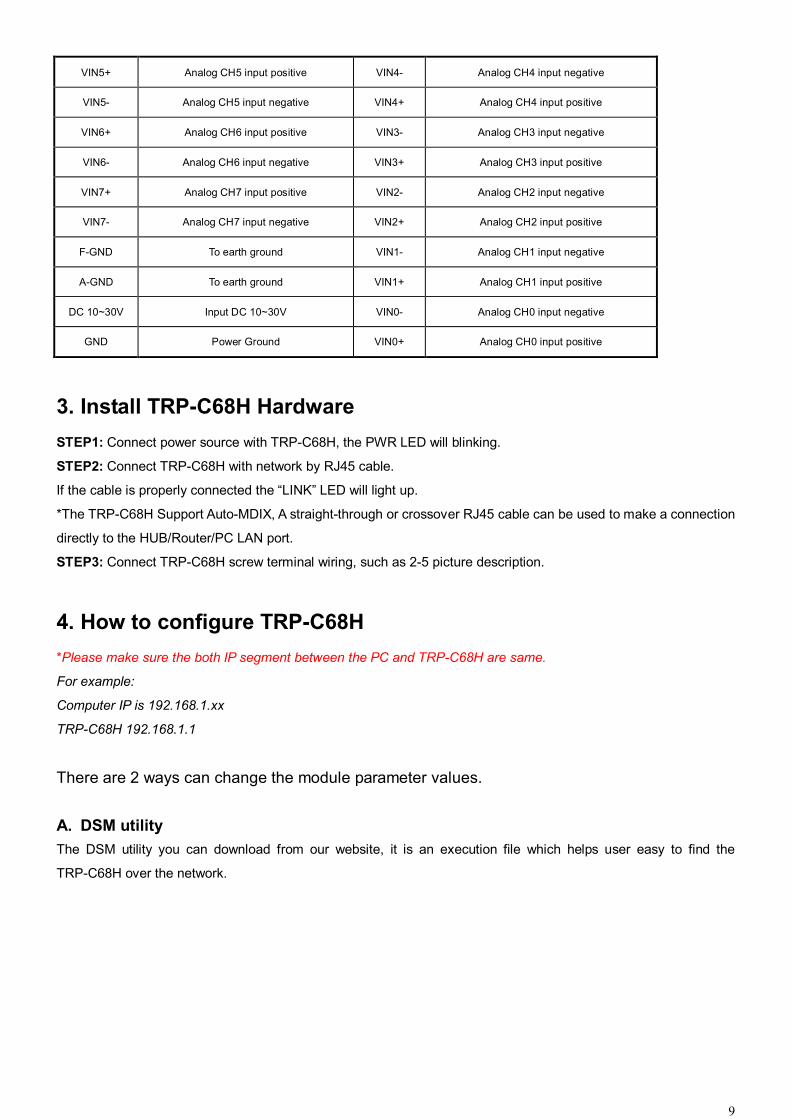
2-7. Pin Description
9
VIN5+ Analog CH5 input positive VIN4- Analog CH4 input negative
VIN5- Analog CH5 input negative VIN4+ Analog CH4 input positive
VIN6+ Analog CH6 input positive VIN3- Analog CH3 input negative
VIN6- Analog CH6 input negative VIN3+ Analog CH3 input positive
VIN7+ Analog CH7 input positive VIN2- Analog CH2 input negative
VIN7- Analog CH7 input negative VIN2+ Analog CH2 input positive
F-GND To earth ground VIN1- Analog CH1 input negative
A-GND To earth ground VIN1+ Analog CH1 input positive
DC 10~30V Input DC 10~30V VIN0- Analog CH0 input negative
GND Power Ground VIN0+ Analog CH0 input positive
3. Install TRP-C68H Hardware STEP1: Connect power source with TRP-C68H, the PWR LED will blinking.
STEP2: Connect TRP-C68H with network by RJ45 cable.
If the cable is properly connected the “LINK” LED will light up.
*The TRP-C68H Support Auto-MDIX, A straight-through or crossover RJ45 cable can be used to make a connection
directly to the HUB/Router/PC LAN port.
STEP3: Connect TRP-C68H screw terminal wiring, such as 2-5 picture description.
4. How to configure TRP-C68H *Please make sure the both IP segment between the PC and TRP-C68H are same.
For example:
Computer IP is 192.168.1.xx
TRP-C68H 192.168.1.1
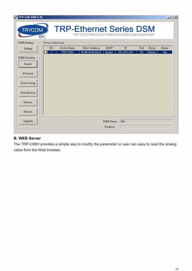
There are 2 ways can change the module parameter values. A. DSM utility The DSM utility you can download from our website, it is an execution file which helps user easy to find the
TRP-C68H over the network.
10
B. WEB Server The TRP-C68H provides a simple way to modify the parameter or user can easy to read the analog value from the Web browser.

11
4-1. Using DSM Utility The DSM utility software performs several functions:
A: Searching for TRP-C68H connected to the network.
B: Displaying and changing the configuration.
C: Upgrading the TRP-C68H firmware, Refer the Firmware upgrade help file.
D: Saving and Loading Configuration from external log File or memory.
4-2. Searching TRP-C68H Once TRP-C68H is connected to the network the DSM software will search it and display it in a window by name, IP
address, Mac….Information.
12
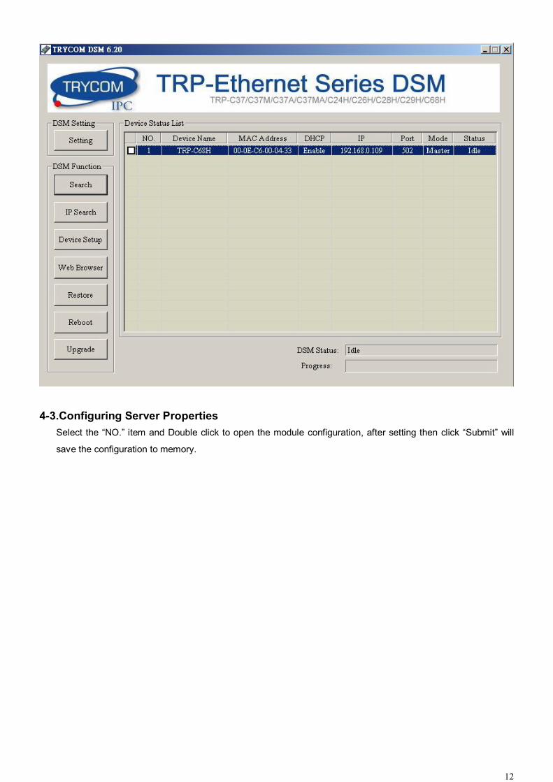
4-3.Configuring Server Properties Select the “NO.” item and Double click to open the module configuration, after setting then click “Submit” will
save the configuration to memory.
13
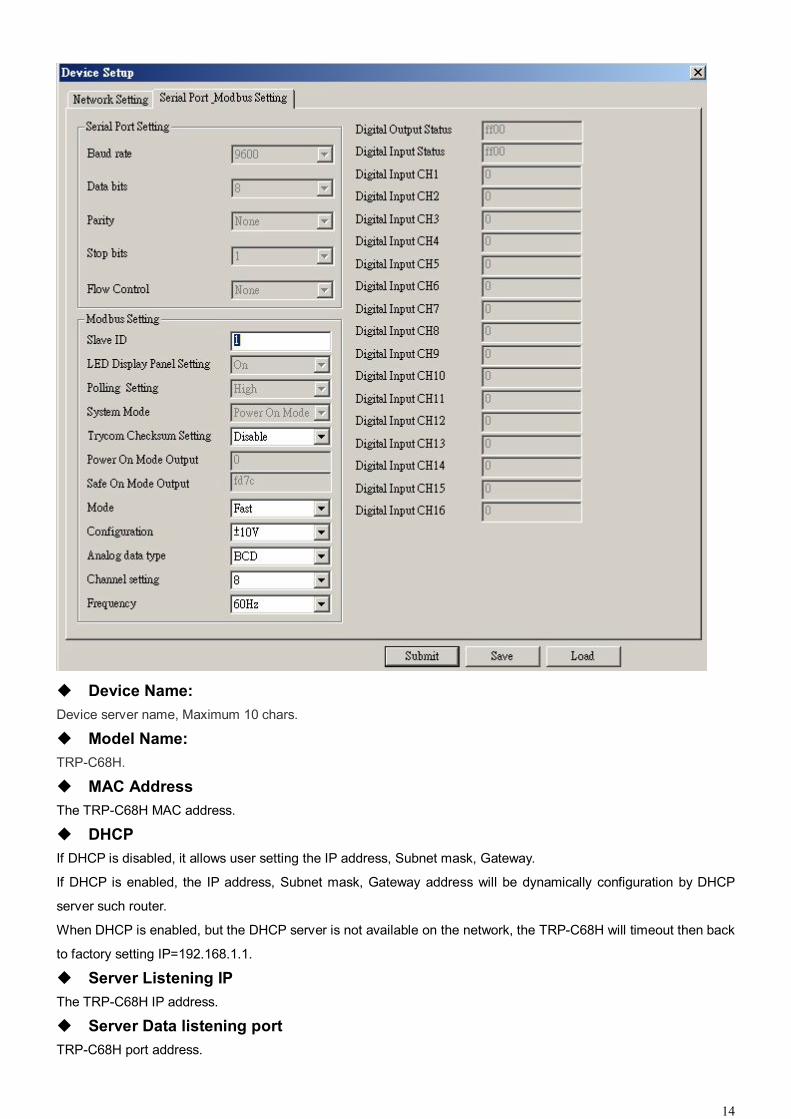
14
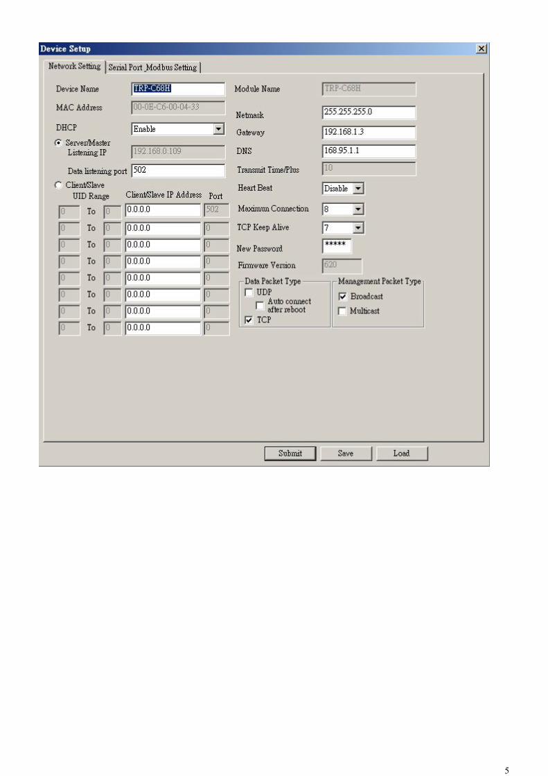
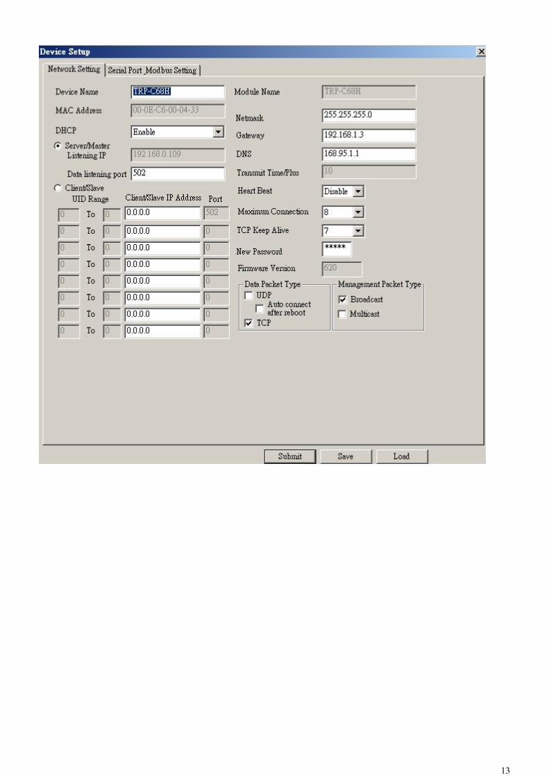
Device Name: Device server name, Maximum 10 chars.
Model Name: TRP-C68H.
MAC Address The TRP-C68H MAC address.
DHCP If DHCP is disabled, it allows user setting the IP address, Subnet mask, Gateway.
If DHCP is enabled, the IP address, Subnet mask, Gateway address will be dynamically configuration by DHCP
server such router.
When DHCP is enabled, but the DHCP server is not available on the network, the TRP-C68H will timeout then back
to factory setting IP=192.168.1.1.
Server Listening IP The TRP-C68H IP address.
Server Data listening port TRP-C68H port address.

15
Client Destination IP When user using the pair mode, the client setting need to input module IP and port which one need to connect.
Client Destination port Client port address.
Port: 16 bit number. (1 ~ 65535)
Netmask The default LAN Netmask is configured for a Class C address. This maybe reconfigured by the user.
Gateway Input the gateway IP address that can be allows users to access the serial server from internet.
DNS Short for Domain Name System, an Internet service that translates domain names into IP addresses. Because
domain names are alphabetic, they're easier to remember. The Internet however, is really based on IP addresses.
Every time you use a domain name, therefore, a DNS service must translate the name into the corresponding IP
address.
Transmit Timer: This feature is only available to Serial Server TRP-C37 and TRP-C37M. Maximum Connection: 1~16 The function allows the user to configure the TRP-C68H in Server mode, adjust 1~16 TCP client host connections.
TCP Keep Alive: 1~7 /Minute When TRP-C68H in Server or Client mode, the TRP-C68H without data over the 1~7 Min setting value,
The TRP-C68H will be disconnecting TCP port.
New Password: 12345 It only accepts value from10000~65535 integer, if input the wrong password over 5 times, the WEB-Page will lock
until the TRP-C68H re-boot.
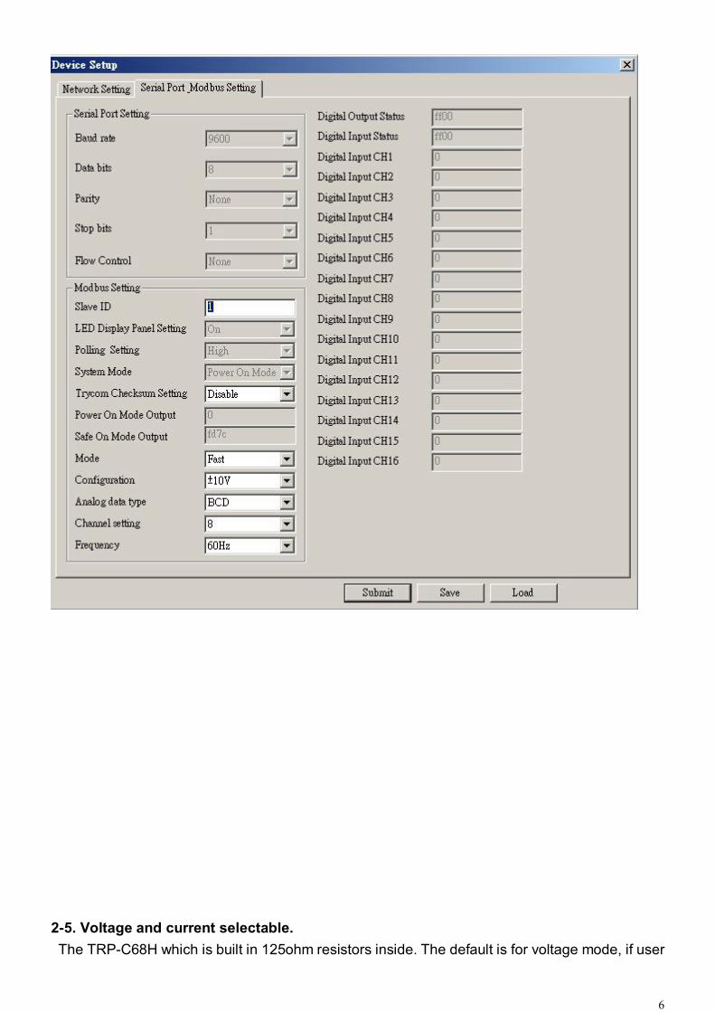
Firmware Version: ABC Slave ID:1~255. ID performs MODBUS RTU / ASCII and TRP-ASCII will use to address.
LED Display Panel Setting :ON/OFF No used
Polling Setting: High/Low. No used
System Mode No used
Trycom Checksum setting: Disable/Enable. TRP-ASCII command used bit checksum.
Power On Mode Output: 0000~FFFF. No used.
Save ON Mode Output:0000~FFFF. No used.
Mode:Fast/Normal. Fast Mode: 2 Bytes, The analog chipset reads the data speed is very fast.
This mode suitable the Modbus poll or Modscan utility.
Normal Mode:3 Byte,The analog chipset reads the data speed is normal.

16
This data output 3 bytes.
Configuration:+/-10V,+/-5V,+/-2.5V,+/-1.25V,+/-650mV,+/-20mA,+4~20mA. Selecting the mode for the analog Voltage or Current input.
Analog Data Type: BCD, PRECENT, HEX. Selecting the display data way for the Decimal, Percentage or Hexadecimal.
Channel Setting:1~8. There are eight channels input Disable or Enable.
Frequency:50Hz/60Hz. Display last stored in the memory of the digital input counter value.
Submit Save the setting value to memory.
Save Save the setting value to external log file.
Load Load the setting value to external log file.
Upgrade Upgrade the TRP-C68H firmware.
4-4.Using the WEB Server mode The Web Server can be used to configure the TRP-C68H from any web browser software (such as I.E).
In Internet Explorer type the IP Address of the TRP-C68H into the address field and press the Enter key. The
following window will appear:
Example:
If TRP-C68H’s IP is 192.168.1.1 ,Please Input the 192.168.1.1 then enters at web address, the web-page
will appear.

17
18
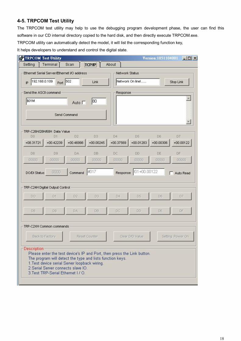
4-5. TRPCOM Test Utility The TRPCOM test utility may help to use the debugging program development phase, the user can find this
software in our CD internal directory copied to the hard disk, and then directly execute TRPCOM.exe.
TRPCOM utility can automatically detect the model, it will list the corresponding function key,
It helps developers to understand and control the digital state.
19
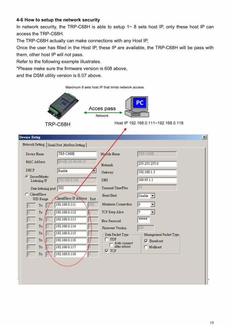
4-6 How to setup the network security In network security, the TRP-C68H is able to setup 1~ 8 sets host IP, only these host IP can access the TRP-C68H. The TRP-C68H actually can make connections with any Host IP, Once the user has filled in the Host IP, these IP are available, the TRP-C68H will be pass with them, other host IP will not pass. Refer to the following example illustrates. *Please make sure the firmware version is 608 above, and the DSM utility version is 6.07 above.
20
5. TRP-ASCII Communication Protocol TRP-C68H supports three modes of communication Protocol TRP-ASCII, Modbus RTU, Modbus ASCII.
TRP-ASCII Command Protocol Description
Command Format :”Leading Code”+”ID Address”+”Command”+”CHK”+(cr) .
at :”Leading Code”+”ID Address”+”Data”+”CHK”+(cr) .
How to calculate the checksum
1. Calculate all characters of the command string to get the ASCII sum, except the character return.
2. Mask the sum of string with 0FFH.
Example:
Send the command is “$06M”.
Sum of string is “$”+”0”+”6”+”M”=“24H”+”30H”+” 4D“=“A1H”……The checksum and [CHK]=“A1”.
Response string with checksum is :” A1“.
TRP-ASCII: ease of use TRP-ASCII integration to develop their own software, such as VB, VC .
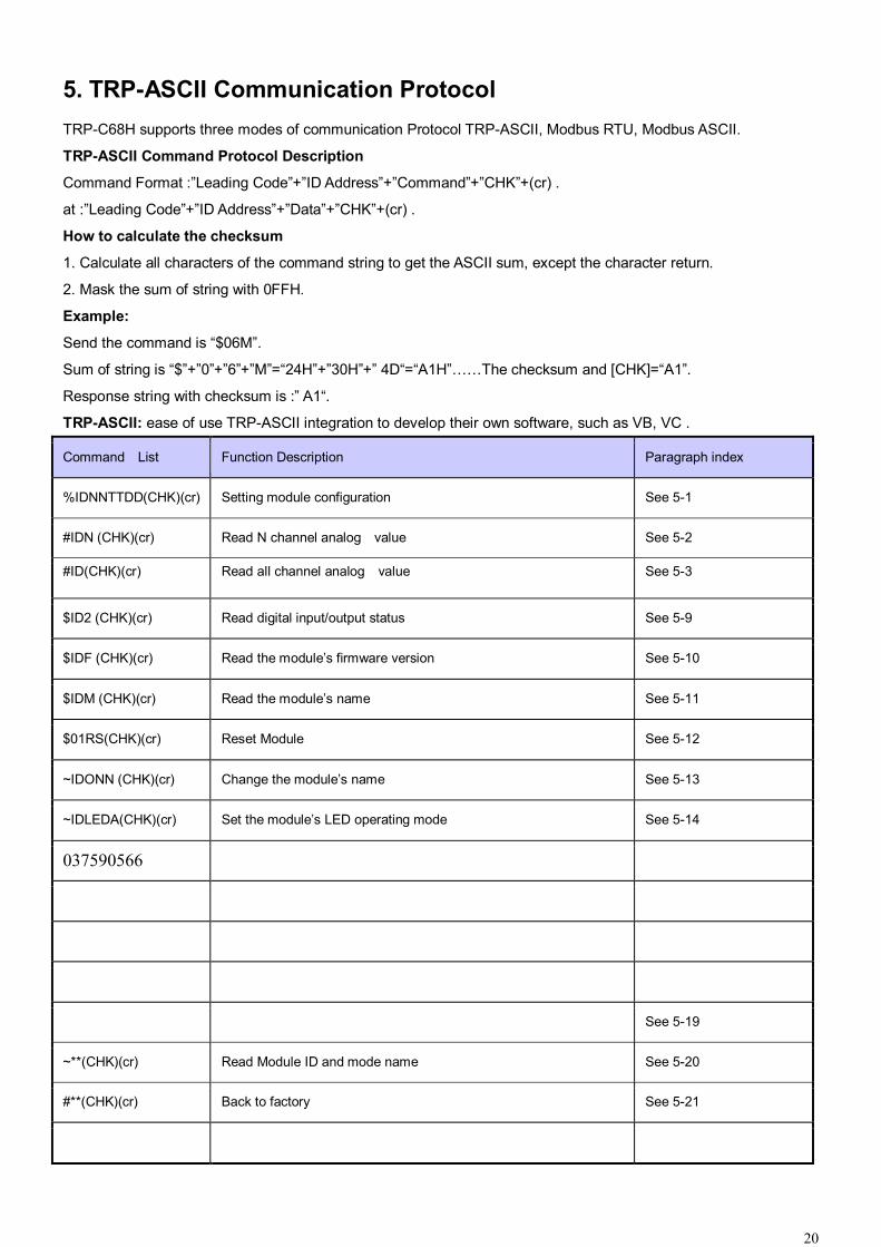
Command List Function Description Paragraph index
%IDNNTTDD(CHK)(cr) Setting module configuration See 5-1
#IDN (CHK)(cr) Read N channel analog value See 5-2
#ID(CHK)(cr) Read all channel analog value See 5-3
$ID2 (CHK)(cr) Read digital input/output status See 5-9
$IDF (CHK)(cr) Read the module’s firmware version See 5-10
$IDM (CHK)(cr) Read the module’s name See 5-11
$01RS(CHK)(cr) Reset Module See 5-12
~IDONN (CHK)(cr) Change the module’s name See 5-13
~IDLEDA(CHK)(cr) Set the module’s LED operating mode See 5-14
037590566
See 5-19
~**(CHK)(cr) Read Module ID and mode name See 5-20
#**(CHK)(cr) Back to factory See 5-21