system technology for ci521-modtcp, ci522-modtcp · 1.2 system technology of the communication...
TRANSCRIPT
1.2 System Technology of the Communication Interface Modules1.2.1 Modbus Communication Interface Module1.2.1.1 OverviewThe Modbus TCP bus module CI52x-MODTCP is used as decentralized I/O module in Modbus TCP net-works. The network connection is performed via 2 RJ45 connectors which are integrated in the terminal unit.
CI521-MODTCPI/O channels properties:n 4 analog inputs (1.0...1.3)n 2 analog outputs (1.5...1.6)n 8 digital inputs 24 VDC in 1 group (2.0...2.7)n 8 digital outputs 24 VDC in 1 group (3.0...3.7)
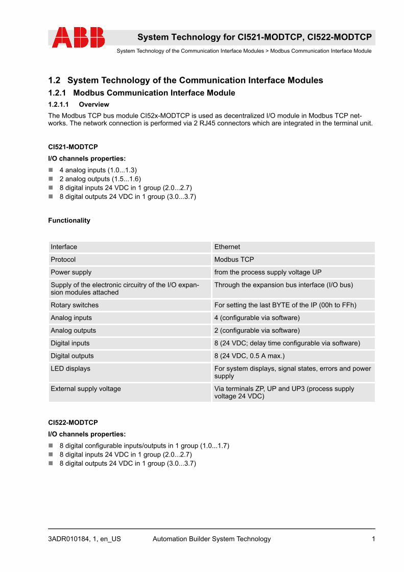
Functionality
Interface Ethernet
Protocol Modbus TCP
Power supply from the process supply voltage UP
Supply of the electronic circuitry of the I/O expan-sion modules attached
Through the expansion bus interface (I/O bus)
Rotary switches For setting the last BYTE of the IP (00h to FFh)
Analog inputs 4 (configurable via software)
Analog outputs 2 (configurable via software)
Digital inputs 8 (24 VDC; delay time configurable via software)
Digital outputs 8 (24 VDC, 0.5 A max.)
LED displays For system displays, signal states, errors and powersupply
External supply voltage Via terminals ZP, UP and UP3 (process supplyvoltage 24 VDC)
CI522-MODTCPI/O channels properties:n 8 digital configurable inputs/outputs in 1 group (1.0...1.7)n 8 digital inputs 24 VDC in 1 group (2.0...2.7)n 8 digital outputs 24 VDC in 1 group (3.0...3.7)
System Technology for CI521-MODTCP, CI522-MODTCPSystem Technology of the Communication Interface Modules > Modbus Communication Interface Module
3ADR010184, 1, en_US Automation Builder System Technology 1

Functionality
Interface Ethernet
Protocol Modbus TCP
Power supply from the process supply voltage UP
Supply of the electronic circuitry of the I/O expan-sion modules attached
Through the expansion bus interface (I/O bus)
Rotary switches For setting the last BYTE of the IP (00h to FFh)
Configurable digital inputs/outputs 8 (configurable via software)
Digital inputs 8 (24 VDC; delay time configurable via software)
Digital outputs 8 (24 VDC, 0.5 A max.)
LED displays For system displays, signal states, errors and powersupply
External supply voltage Via terminals ZP, UP and UP3 (process supplyvoltage 24 VDC)
The inputs/outputs are electrically isolated from the Ethernet network. There is no potential separationbetween the channels.
The configuration of the inputs/outputs is performed by software.
For usage in enhanced ambient conditions (e.g. wider temperature and humidity range), a special XC ver-sion of the device is available.
1.2.1.2 Modbus TCP Registers1.2.1.2.1 Register Layout for CI52x-MODTCPThe registers can be divided in 4 sections:
n Information data section 0x0000 to 0x0D50 (for acyclic use)n I/O data and diagnosis section 0x0FFA to 0x2B00 (for cyclic use)n Parameter data section 0x3000 to 0x3B00 (for acyclic use)n Special functionality section 0x5A00 to 0x6A00 (for acyclic use)
System Technology for CI521-MODTCP, CI522-MODTCPSystem Technology of the Communication Interface Modules > Modbus Communication Interface Module
3ADR010184, 1, en_USAutomation Builder System Technology2

1.2.1.2.2 Information Data Section (Acyclic Data)The information data section can be used to read out common and module specific information.
This section is read only.
Register (hex) Description Readable byModbus func-tion code
Writeable byModbus functioncode
0 Device and FW information CI 3 x
50 Production data CI 3 x
100 Device and FW information 1. EXP 3 x
125 Device and FW information 1. Hot swap terminalunit
3 *) x
150 Production data 1. EXP 3 x
175 Production data 1. Hot swap terminal unit 3 *) x
... ... x
A00 Device and FW information 10. EXP 3 x
A25 Device and FW information 10. Hot swap ter-minal unit
3 *) x
A50 Production data 10. EXP 3 x
A75 Production data 10. Hot swap terminal unit 3 *) x
D00 Common device information 3 x
*) supported from CI52x firmware version V3.2.0 (device index F0)
This section can be divided again in two sections:
n The module specific section (containing information for each module CI52x-MODTCP and expansionmodules and hot swap terminal units)
n The common device information block
The Module Specific Information RegistersFor each module (CI52x device, expansion modules and hot swap terminal units) the following data can beread out:
n Device and FW informationThis section consists of 20 WORDs per module and contains information on each module using the fol-lowing structure:
Data DATA TYPE Description
Module ID WORD The module ID of the requested module
Module name ARRAY [1..10] OF BYTE The module name of the requested module
System Technology for CI521-MODTCP, CI522-MODTCPSystem Technology of the Communication Interface Modules > Modbus Communication Interface Module
3ADR010184, 1, en_US Automation Builder System Technology 3

Data DATA TYPE Description
Version 1st processor ARRAY [1..4] OF BYTE The version of the 1st processor of the requestedmodule
Version 2nd processor ARRAY [1..4] OF BYTE The version of the 2nd processor of the requestedmodule
Version 3rd processor ARRAY [1..4] OF BYTE The version of the 3rd processor of the requestedmodule
Version 4th processor ARRAY [1..4] OF BYTE The version of the 4th processor of the requestedmodule
Hardware version 1) ARRAY [1..4] OF BYTE The hardware version of the 4 processors
Reserved ARRAY [1..8] OF BYTE
ARRAY [1..4] OF BYTE 2)
Reserved
Number input data WORD Number of input data of the requested module inBYTES
Number output data WORD Number of output data of the requested module inBYTES
1) supported from CI52x firmware version V3.2.0 (device index F0)2) from CI52x firmware version V3.2.0 (device index F0) “Reserved” is ARRAY [1..4] OF BYTE
n Production / Traceability data:This section consists of 25 WORDs per module and contains the traceability data for each module usingfollowing structure:– Article number: Byte 01..15– Index: Byte 16..17– Name: Byte 18..29– Production date: Byte 30..33– Key number: Byte 34..38– Site: Byte 39..40– Year: Byte 41..42– Serial number: Byte 41..50 (The serial number implies the year)
n Production / Traceability data from CI5x2 firmware version V3.2.0 (device index F0):This section consists of 26 WORDs per module and contains the traceability data for each module usingfollowing structure:– Article number: Byte 01..15– Index: Byte 16..17– Name: Byte 18..31– Production date: Byte 32..35– Key number: Byte 36..40– Site: Byte 41..42– Year: Byte 43..44– Serial number: Byte 42..52 (The serial number implies the year)
System Technology for CI521-MODTCP, CI522-MODTCPSystem Technology of the Communication Interface Modules > Modbus Communication Interface Module
3ADR010184, 1, en_USAutomation Builder System Technology4
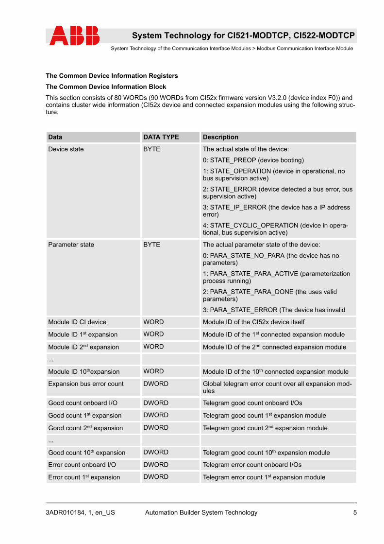
The Common Device Information RegistersThe Common Device Information BlockThis section consists of 80 WORDs (90 WORDs from CI52x firmware version V3.2.0 (device index F0)) andcontains cluster wide information (CI52x device and connected expansion modules using the following struc-ture:
Data DATA TYPE Description
Device state BYTE The actual state of the device:
0: STATE_PREOP (device booting)
1: STATE_OPERATION (device in operational, nobus supervision active)
2: STATE_ERROR (device detected a bus error, bussupervision active)
3: STATE_IP_ERROR (the device has a IP addresserror)
4: STATE_CYCLIC_OPERATION (device in opera-tional, bus supervision active)
Parameter state BYTE The actual parameter state of the device:
0: PARA_STATE_NO_PARA (the device has noparameters)
1: PARA_STATE_PARA_ACTIVE (parameterizationprocess running)
2: PARA_STATE_PARA_DONE (the uses validparameters)
3: PARA_STATE_ERROR (The device has invalid
Module ID CI device WORD Module ID of the CI52x device itself
Module ID 1st expansion WORD Module ID of the 1st connected expansion module
Module ID 2nd expansion WORD Module ID of the 2nd connected expansion module
...
Module ID 10thexpansion WORD Module ID of the 10th connected expansion module
Expansion bus error count DWORD Global telegram error count over all expansion mod-ules
Good count onboard I/O DWORD Telegram good count onboard I/Os
Good count 1st expansion DWORD Telegram good count 1st expansion module
Good count 2nd expansion DWORD Telegram good count 2nd expansion module
...
Good count 10th expansion DWORD Telegram good count 10th expansion module
Error count onboard I/O DWORD Telegram error count onboard I/Os
Error count 1st expansion DWORD Telegram error count 1st expansion module
System Technology for CI521-MODTCP, CI522-MODTCPSystem Technology of the Communication Interface Modules > Modbus Communication Interface Module
3ADR010184, 1, en_US Automation Builder System Technology 5

Data DATA TYPE Description
Error count 2nd expansion DWORD Telegram error count 2nd expansion module
...
Error count 10th expansion DWORD Telegram error count 10th expansion module
Input address onboard I/O WORD Modbus TCP register address for inputs of theonboard I/Os
Input address 1st expansion WORD Modbus TCP register address for inputs of the 1st
expansion module
Input address 2nd expansion WORD Modbus TCP register address for inputs of the 2nd
expansion module
...
Input address 10th expansion WORD Modbus TCP register address for inputs of the 10th
expansion module
Output address onboard I/O WORD Modbus TCP register address for outputs of theonboard I/Os
Output address 1st expansion WORD Modbus TCP register address for outputs of the 1st
expansion module
Output address 2nd expansion WORD Modbus TCP register address for outputs of the 2nd
expansion module
...
Output address 10th expansion WORD Modbus TCP register address for outputs of the 10th
expansion module
Module ID 1st hot swap ter-minal unit *)
WORD Module ID of the 1st connected hot swap terminalunit *)
Module ID 2nd hot swap ter-minal unit *)
WORD Module ID of the 2nd connected hot swap terminalunit *)
...
Module ID 10th hot swap ter-minal unit *)
WORD Module ID of the 10th connected hot swap terminalunit *)
*) supported from CI52x firmware version V3.2.0 (device index F0)
1.2.1.2.3 I/O / Process Data and Diagnosis Section (Cyclic Data)The cyclic data section for CI52x-MODTCP
Register (hex) Description Readable byModbus func-tion code
Writeable byModbus functioncode
FCE *) Module state 3,4, 23 x
FFA Diagnosis 3,4, 23 x
System Technology for CI521-MODTCP, CI522-MODTCPSystem Technology of the Communication Interface Modules > Modbus Communication Interface Module
3ADR010184, 1, en_USAutomation Builder System Technology6
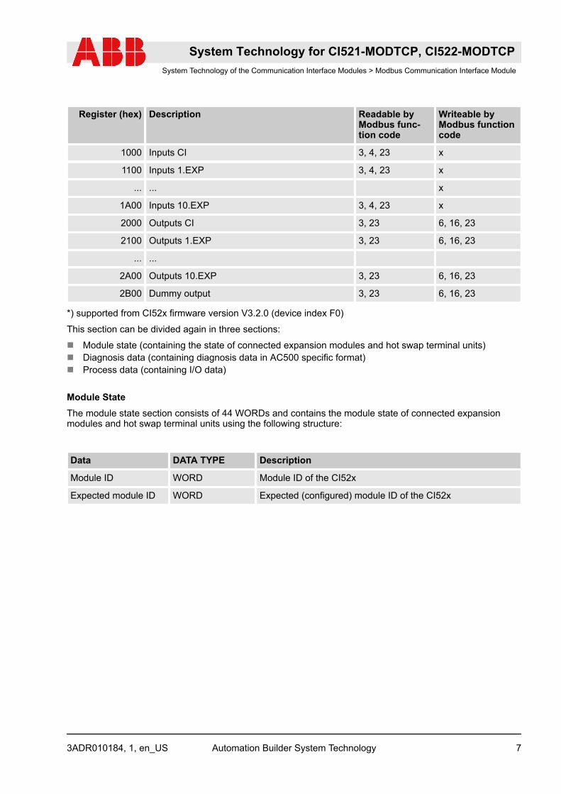
Register (hex) Description Readable byModbus func-tion code
Writeable byModbus functioncode
1000 Inputs CI 3, 4, 23 x
1100 Inputs 1.EXP 3, 4, 23 x
... ... x
1A00 Inputs 10.EXP 3, 4, 23 x
2000 Outputs CI 3, 23 6, 16, 23
2100 Outputs 1.EXP 3, 23 6, 16, 23
... ...
2A00 Outputs 10.EXP 3, 23 6, 16, 23
2B00 Dummy output 3, 23 6, 16, 23
*) supported from CI52x firmware version V3.2.0 (device index F0)
This section can be divided again in three sections:
n Module state (containing the state of connected expansion modules and hot swap terminal units)n Diagnosis data (containing diagnosis data in AC500 specific format)n Process data (containing I/O data)
Module StateThe module state section consists of 44 WORDs and contains the module state of connected expansionmodules and hot swap terminal units using the following structure:
Data DATA TYPE Description
Module ID WORD Module ID of the CI52x
Expected module ID WORD Expected (configured) module ID of the CI52x
System Technology for CI521-MODTCP, CI522-MODTCPSystem Technology of the Communication Interface Modules > Modbus Communication Interface Module
3ADR010184, 1, en_US Automation Builder System Technology 7

Data DATA TYPE Description
Module state BYTE The current module state of the CI52x:
0: NO_MOD (no module detected)
1: MOD_INIT (module detected, module is in initializationphase)
2: MOD_RUN (module detected and running or in failsafestate, input data are valid)
3: WRONG_MOD (wrong module detected, module IDdoesn’t match expected module ID)
4: MOD_REMOVED (module removed or defective on hotswap terminal unit, no communication to module possible)
5: MOD_ERROR (module defective on hot swap terminalunit, no communication to module possible)
6: MOD_LOST (lost communication to module on not hotswap capable terminal unit)
7: UNKNOWN (module detected but not configured)
Diagnosis flag BYTE Diagnosis flag for the CI52x:
0: NO_DIAG (no diagnosis evailable from CI52x I/O cards)
1: DIAG_AVAILABLE (diagnosis available for CI52x I/Ocards)
Terminal unit state BYTE Terminal unit state for the CI52x:
0: NO_HOTSWAP_TU (not hot swap terminal unit detected)
1: HOTSWAP_TU_RUNNING (hot swap terminal unitdetected and working)
2: HOTSWAP_TU_ERROR (hot swap terminal unit detected,but communication errors for hot swap terminal unit detected)
Parameter state BYTE Parameter state of the CI52x:
0: NO_PARA (module is in initialization phase and not readyfor parameterization)
1: WAIT_PARA (module awaits parameterization)
2: PARA_RUN (parameterization running)
3: LEN_ERR (length of parameters not correct)
4: ID_ERR (module ID inside parameters not correct)
5: PARA_DONE (parameterization finished without errors)
Module ID WORD Module ID of the 1st connected expansion module
Expected module ID WORD Expected (configured) module ID of the 1st connected expan-sion module
Module state BYTE The current module state of the 1st connected expansionmodule
System Technology for CI521-MODTCP, CI522-MODTCPSystem Technology of the Communication Interface Modules > Modbus Communication Interface Module
3ADR010184, 1, en_USAutomation Builder System Technology8

Data DATA TYPE Description
Diagnosis flag BYTE Diagnosis flag for the 1st connected expansion module
0: NO_DIAG (no diagnosis evailable for expansion module)
1: DIAG_AVAILABLE (diagnosis available for expansionmodule)
Terminal unit state BYTE Terminal unit state for the 1st connected expansion module
Parameter state BYTE Parameter state of the 1st connected expansion module
...
Module ID WORD Module ID of the 10th connected expansion module
Expected module ID WORD Expected (configured) module ID of the 10th connectedexpansion module
Module state BYTE The current module state of the 10th connected expansionmodule
Diagnosis flag BYTE Diagnosis flag for the 10th connected expansion module
Terminal unit state BYTE Terminal unit state for the 10th connected expansion module
Parameter state BYTE Parameter state of the 10th connected expansion module
Diagnosis DataThe diagnosis data section contains one diagnostic message with the following structure (according toAC500 diagnosis):
ByteNumber
Description Possible Values
1 Diagnosis Byte, slotnumber
31 = CI52x-MODTCP (e. g. error at integrated 8 DI / 8 DO)
1 = 1st connected S500 I/O Module
...
10 = 10th connected S500 I/O Module
2 Diagnosis Byte, modulenumber
According to the I/O bus specification passed on by modules tothe fieldbus master
3 Diagnosis Byte, channel According to the I/O bus specification passed on by modules tothe fieldbus master
System Technology for CI521-MODTCP, CI522-MODTCPSystem Technology of the Communication Interface Modules > Modbus Communication Interface Module
3ADR010184, 1, en_US Automation Builder System Technology 9
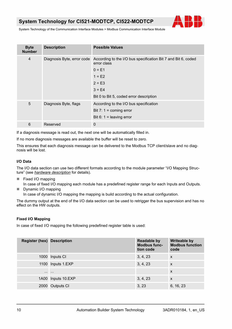
ByteNumber
Description Possible Values
4 Diagnosis Byte, error code According to the I/O bus specification Bit 7 and Bit 6, codederror class
0 = E1
1 = E2
2 = E3
3 = E4
Bit 0 to Bit 5, coded error description
5 Diagnosis Byte, flags According to the I/O bus specification
Bit 7: 1 = coming error
Bit 6: 1 = leaving error
6 Reserved 0
If a diagnosis message is read out, the next one will be automatically filled in.
If no more diagnosis messages are available the buffer will be reset to zero.
This ensures that each diagnosis message can be delivered to the Modbus TCP client/slave and no diag-nosis will be lost.
I/O DataThe I/O data section can use two different formats according to the module parameter “I/O Mapping Struc-ture” (see hardware description for details).
n Fixed I/O mappingIn case of fixed I/O mapping each module has a predefined register range for each Inputs and Outputs.
n Dynamic I/O mappingIn case of dynamic I/O mapping the mapping is build according to the actual configuration.
The dummy output at the end of the I/O data section can be used to retrigger the bus supervision and has noeffect on the HW outputs.
Fixed I/O MappingIn case of fixed I/O mapping the following predefined register table is used:
Register (hex) Description Readable byModbus func-tion code
Writeable byModbus functioncode
1000 Inputs CI 3, 4, 23 x
1100 Inputs 1.EXP 3, 4, 23 x
... ... x
1A00 Inputs 10.EXP 3, 4, 23 x
2000 Outputs CI 3, 23 6, 16, 23
System Technology for CI521-MODTCP, CI522-MODTCPSystem Technology of the Communication Interface Modules > Modbus Communication Interface Module
3ADR010184, 1, en_USAutomation Builder System Technology10
Register (hex) Description Readable byModbus func-tion code
Writeable byModbus functioncode
2100 Outputs 1.EXP 3, 23 6, 16, 23
... ...
2A00 Outputs 10.EXP 3, 23 6, 16, 23
2B00 Dummy output 3, 23 6, 16, 23
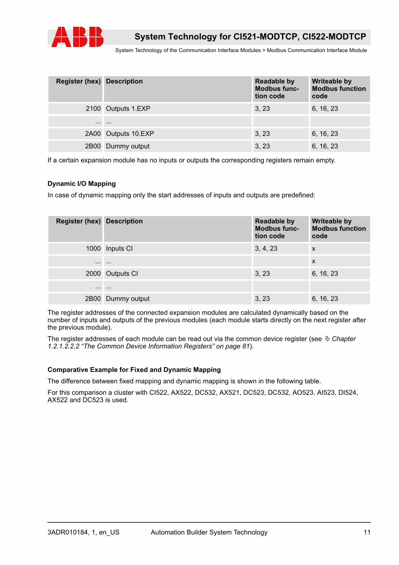
If a certain expansion module has no inputs or outputs the corresponding registers remain empty.
Dynamic I/O MappingIn case of dynamic mapping only the start addresses of inputs and outputs are predefined:
Register (hex) Description Readable byModbus func-tion code
Writeable byModbus functioncode
1000 Inputs CI 3, 4, 23 x
... ... x
2000 Outputs CI 3, 23 6, 16, 23
... ...
2B00 Dummy output 3, 23 6, 16, 23
The register addresses of the connected expansion modules are calculated dynamically based on thenumber of inputs and outputs of the previous modules (each module starts directly on the next register afterthe previous module).
The register addresses of each module can be read out via the common device register (see Ä Chapter1.2.1.2.2.2 “The Common Device Information Registers” on page 81).
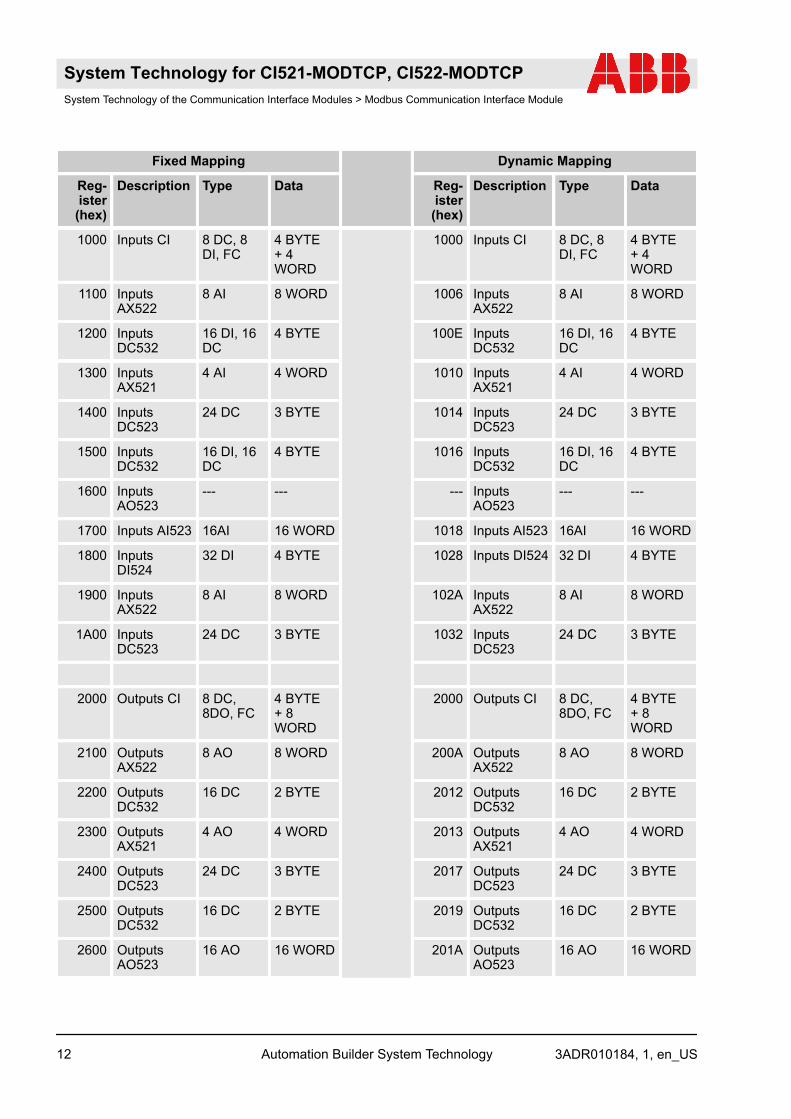
Comparative Example for Fixed and Dynamic MappingThe difference between fixed mapping and dynamic mapping is shown in the following table.
For this comparison a cluster with CI522, AX522, DC532, AX521, DC523, DC532, AO523, AI523, DI524,AX522 and DC523 is used.
System Technology for CI521-MODTCP, CI522-MODTCPSystem Technology of the Communication Interface Modules > Modbus Communication Interface Module
3ADR010184, 1, en_US Automation Builder System Technology 11
Fixed Mapping Dynamic Mapping
Reg-ister(hex)
Description Type Data Reg-ister(hex)
Description Type Data
1000 Inputs CI 8 DC, 8DI, FC
4 BYTE+ 4WORD
1000 Inputs CI 8 DC, 8DI, FC
4 BYTE+ 4WORD
1100 InputsAX522
8 AI 8 WORD 1006 InputsAX522
8 AI 8 WORD
1200 InputsDC532
16 DI, 16DC
4 BYTE 100E InputsDC532
16 DI, 16DC
4 BYTE
1300 InputsAX521
4 AI 4 WORD 1010 InputsAX521
4 AI 4 WORD
1400 InputsDC523
24 DC 3 BYTE 1014 InputsDC523
24 DC 3 BYTE
1500 InputsDC532
16 DI, 16DC
4 BYTE 1016 InputsDC532
16 DI, 16DC
4 BYTE
1600 InputsAO523
--- --- --- InputsAO523
--- ---
1700 Inputs AI523 16AI 16 WORD 1018 Inputs AI523 16AI 16 WORD
1800 InputsDI524
32 DI 4 BYTE 1028 Inputs DI524 32 DI 4 BYTE
1900 InputsAX522
8 AI 8 WORD 102A InputsAX522
8 AI 8 WORD
1A00 InputsDC523
24 DC 3 BYTE 1032 InputsDC523
24 DC 3 BYTE
2000 Outputs CI 8 DC,8DO, FC
4 BYTE+ 8WORD
2000 Outputs CI 8 DC,8DO, FC
4 BYTE+ 8WORD
2100 OutputsAX522
8 AO 8 WORD 200A OutputsAX522
8 AO 8 WORD
2200 OutputsDC532
16 DC 2 BYTE 2012 OutputsDC532
16 DC 2 BYTE
2300 OutputsAX521
4 AO 4 WORD 2013 OutputsAX521
4 AO 4 WORD
2400 OutputsDC523
24 DC 3 BYTE 2017 OutputsDC523
24 DC 3 BYTE
2500 OutputsDC532
16 DC 2 BYTE 2019 OutputsDC532
16 DC 2 BYTE
2600 OutputsAO523
16 AO 16 WORD 201A OutputsAO523
16 AO 16 WORD
System Technology for CI521-MODTCP, CI522-MODTCPSystem Technology of the Communication Interface Modules > Modbus Communication Interface Module
3ADR010184, 1, en_USAutomation Builder System Technology12
Fixed Mapping Dynamic Mapping
Reg-ister(hex)
Description Type Data Reg-ister(hex)
Description Type Data
2700 OutputsAI523
--- --- --- OutputsAI523
--- ---
2800 OutputsDI524
--- --- --- OutputsDI524
--- ---
2900 OutputsAX522
8 AO 8 WORD 202A OutputsAX522
8 AO 8 WORD
2A00 OutputsDC523
24 DC 3 BYTE 2032 OutputsDC523
24 DC 3 BYTE
Process Data Structure CI521-MODTCPI/O data (Inputs 19 BYTEs)
Signal DATA TYPE Description
AI0 WORD Input value of the 1st analogueinput
AI1 WORD Input value of the 2nd analogueinput
AI2 WORD Input value of the 3rd analogueinput
AI3 WORD Input value of the 4th analogueinput
DI BYTE Input value of the DI channels
Fast counter actual value counter1
DWORD Ä Chapter 1.1.8.1 “Fast Countersin AC500 Devices” on page 68
Fast counter actual value counter2
DWORD
Fast counter state counter 1 BYTE
Fast counter state counter 2 BYTE
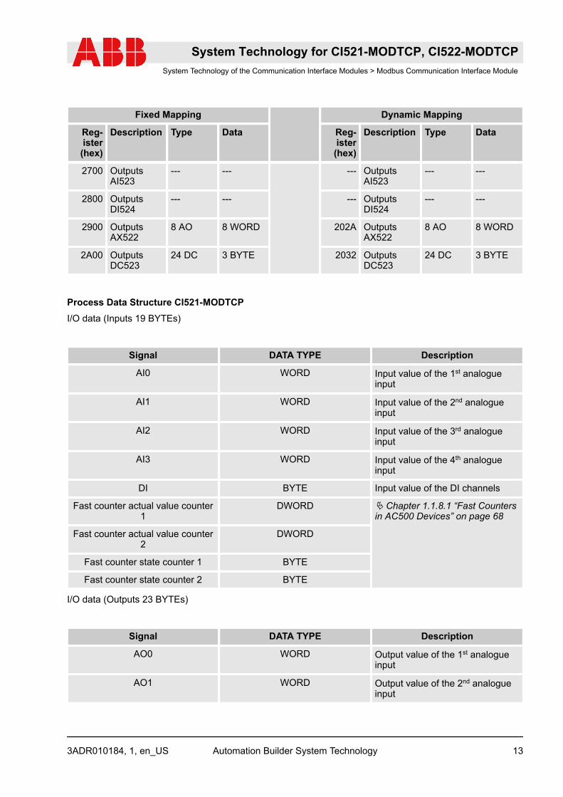
I/O data (Outputs 23 BYTEs)
Signal DATA TYPE Description
AO0 WORD Output value of the 1st analogueinput
AO1 WORD Output value of the 2nd analogueinput
System Technology for CI521-MODTCP, CI522-MODTCPSystem Technology of the Communication Interface Modules > Modbus Communication Interface Module
3ADR010184, 1, en_US Automation Builder System Technology 13
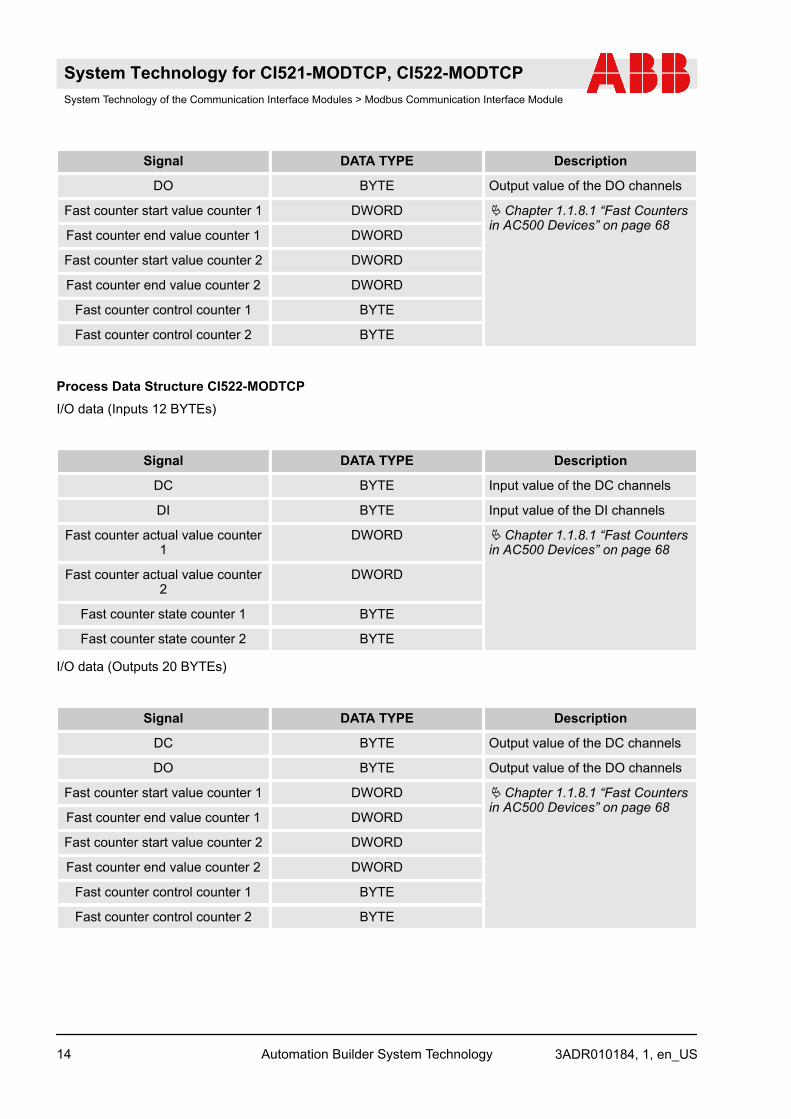
Signal DATA TYPE Description
DO BYTE Output value of the DO channels
Fast counter start value counter 1 DWORD Ä Chapter 1.1.8.1 “Fast Countersin AC500 Devices” on page 68
Fast counter end value counter 1 DWORD
Fast counter start value counter 2 DWORD
Fast counter end value counter 2 DWORD
Fast counter control counter 1 BYTE
Fast counter control counter 2 BYTE
Process Data Structure CI522-MODTCPI/O data (Inputs 12 BYTEs)
Signal DATA TYPE Description
DC BYTE Input value of the DC channels
DI BYTE Input value of the DI channels
Fast counter actual value counter1
DWORD Ä Chapter 1.1.8.1 “Fast Countersin AC500 Devices” on page 68
Fast counter actual value counter2
DWORD
Fast counter state counter 1 BYTE
Fast counter state counter 2 BYTE
I/O data (Outputs 20 BYTEs)
Signal DATA TYPE Description
DC BYTE Output value of the DC channels
DO BYTE Output value of the DO channels
Fast counter start value counter 1 DWORD Ä Chapter 1.1.8.1 “Fast Countersin AC500 Devices” on page 68
Fast counter end value counter 1 DWORD
Fast counter start value counter 2 DWORD
Fast counter end value counter 2 DWORD
Fast counter control counter 1 BYTE
Fast counter control counter 2 BYTE
System Technology for CI521-MODTCP, CI522-MODTCPSystem Technology of the Communication Interface Modules > Modbus Communication Interface Module
3ADR010184, 1, en_USAutomation Builder System Technology14
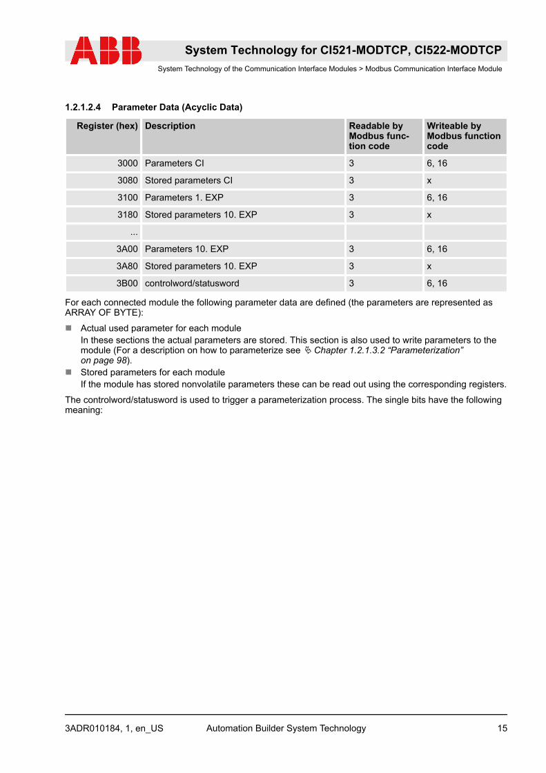
1.2.1.2.4 Parameter Data (Acyclic Data)
Register (hex) Description Readable byModbus func-tion code
Writeable byModbus functioncode
3000 Parameters CI 3 6, 16
3080 Stored parameters CI 3 x
3100 Parameters 1. EXP 3 6, 16
3180 Stored parameters 10. EXP 3 x
...
3A00 Parameters 10. EXP 3 6, 16
3A80 Stored parameters 10. EXP 3 x
3B00 controlword/statusword 3 6, 16
For each connected module the following parameter data are defined (the parameters are represented asARRAY OF BYTE):
n Actual used parameter for each moduleIn these sections the actual parameters are stored. This section is also used to write parameters to themodule (For a description on how to parameterize see Ä Chapter 1.2.1.3.2 “Parameterization”on page 98).
n Stored parameters for each moduleIf the module has stored nonvolatile parameters these can be read out using the corresponding registers.
The controlword/statusword is used to trigger a parameterization process. The single bits have the followingmeaning:
System Technology for CI521-MODTCP, CI522-MODTCPSystem Technology of the Communication Interface Modules > Modbus Communication Interface Module
3ADR010184, 1, en_US Automation Builder System Technology 15
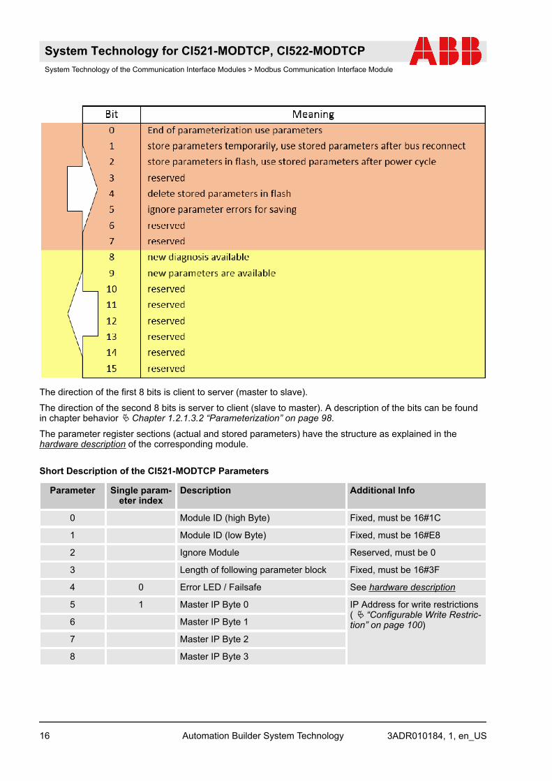
The direction of the first 8 bits is client to server (master to slave).
The direction of the second 8 bits is server to client (slave to master). A description of the bits can be foundin chapter behavior Ä Chapter 1.2.1.3.2 “Parameterization” on page 98.
The parameter register sections (actual and stored parameters) have the structure as explained in thehardware description of the corresponding module.
Short Description of the CI521-MODTCP Parameters
Parameter Single param-eter index
Description Additional Info
0 Module ID (high Byte) Fixed, must be 16#1C
1 Module ID (low Byte) Fixed, must be 16#E8
2 Ignore Module Reserved, must be 0
3 Length of following parameter block Fixed, must be 16#3F
4 0 Error LED / Failsafe See hardware description
5 1 Master IP Byte 0 IP Address for write restrictions( Ä “Configurable Write Restric-tion” on page 100)6 Master IP Byte 1
7 Master IP Byte 2
8 Master IP Byte 3
System Technology for CI521-MODTCP, CI522-MODTCPSystem Technology of the Communication Interface Modules > Modbus Communication Interface Module
3ADR010184, 1, en_USAutomation Builder System Technology16
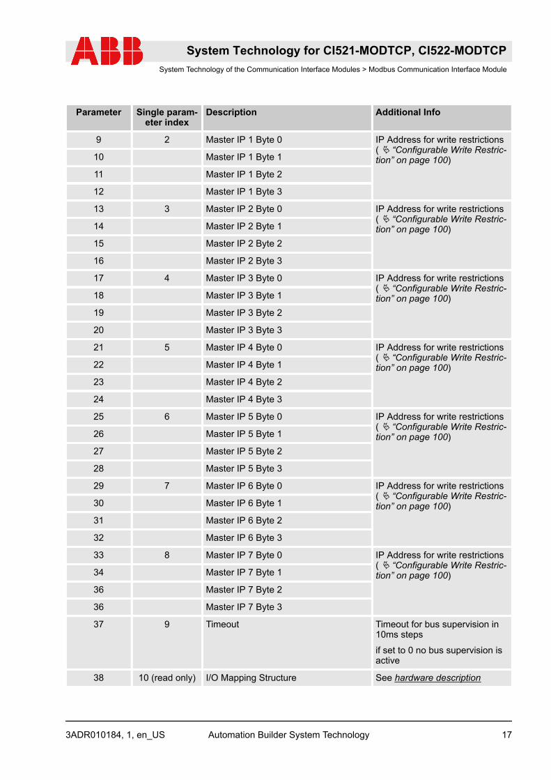
Parameter Single param-eter index
Description Additional Info
9 2 Master IP 1 Byte 0 IP Address for write restrictions( Ä “Configurable Write Restric-tion” on page 100)10 Master IP 1 Byte 1
11 Master IP 1 Byte 2
12 Master IP 1 Byte 3
13 3 Master IP 2 Byte 0 IP Address for write restrictions( Ä “Configurable Write Restric-tion” on page 100)14 Master IP 2 Byte 1
15 Master IP 2 Byte 2
16 Master IP 2 Byte 3
17 4 Master IP 3 Byte 0 IP Address for write restrictions( Ä “Configurable Write Restric-tion” on page 100)18 Master IP 3 Byte 1
19 Master IP 3 Byte 2
20 Master IP 3 Byte 3
21 5 Master IP 4 Byte 0 IP Address for write restrictions( Ä “Configurable Write Restric-tion” on page 100)22 Master IP 4 Byte 1
23 Master IP 4 Byte 2
24 Master IP 4 Byte 3
25 6 Master IP 5 Byte 0 IP Address for write restrictions( Ä “Configurable Write Restric-tion” on page 100)26 Master IP 5 Byte 1
27 Master IP 5 Byte 2
28 Master IP 5 Byte 3
29 7 Master IP 6 Byte 0 IP Address for write restrictions( Ä “Configurable Write Restric-tion” on page 100)30 Master IP 6 Byte 1
31 Master IP 6 Byte 2
32 Master IP 6 Byte 3
33 8 Master IP 7 Byte 0 IP Address for write restrictions( Ä “Configurable Write Restric-tion” on page 100)34 Master IP 7 Byte 1
36 Master IP 7 Byte 2
36 Master IP 7 Byte 3
37 9 Timeout Timeout for bus supervision in10ms steps
if set to 0 no bus supervision isactive
38 10 (read only) I/O Mapping Structure See hardware description
System Technology for CI521-MODTCP, CI522-MODTCPSystem Technology of the Communication Interface Modules > Modbus Communication Interface Module
3ADR010184, 1, en_US Automation Builder System Technology 17
Parameter Single param-eter index
Description Additional Info
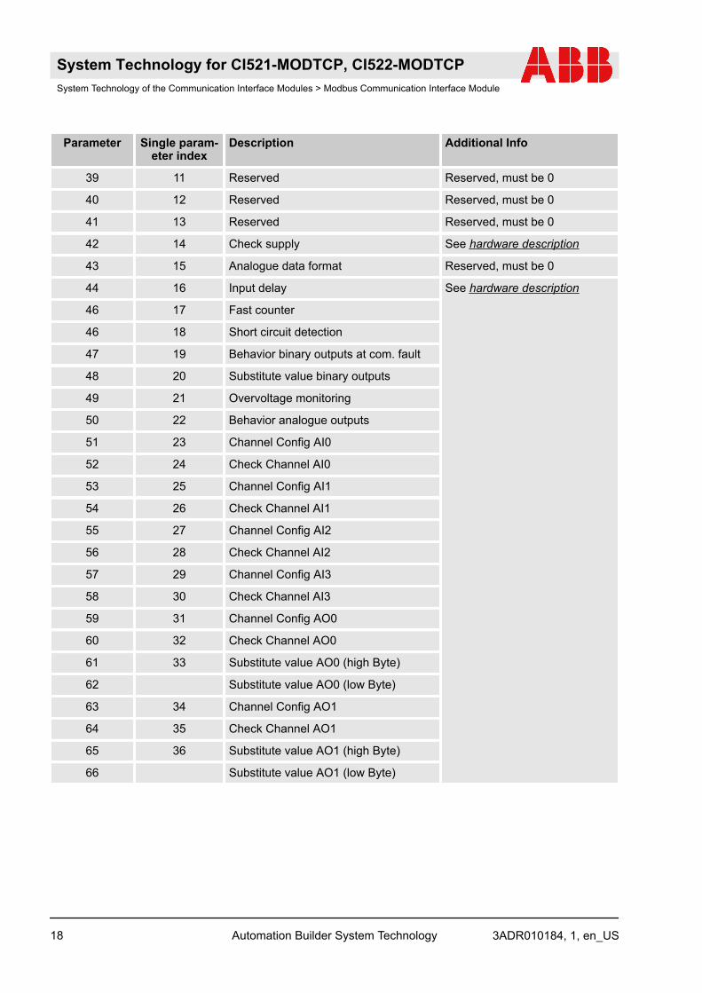
39 11 Reserved Reserved, must be 0
40 12 Reserved Reserved, must be 0
41 13 Reserved Reserved, must be 0
42 14 Check supply See hardware description
43 15 Analogue data format Reserved, must be 0
44 16 Input delay See hardware description
46 17 Fast counter
46 18 Short circuit detection
47 19 Behavior binary outputs at com. fault
48 20 Substitute value binary outputs
49 21 Overvoltage monitoring
50 22 Behavior analogue outputs
51 23 Channel Config AI0
52 24 Check Channel AI0
53 25 Channel Config AI1
54 26 Check Channel AI1
55 27 Channel Config AI2
56 28 Check Channel AI2
57 29 Channel Config AI3
58 30 Check Channel AI3
59 31 Channel Config AO0
60 32 Check Channel AO0
61 33 Substitute value AO0 (high Byte)
62 Substitute value AO0 (low Byte)
63 34 Channel Config AO1
64 35 Check Channel AO1
65 36 Substitute value AO1 (high Byte)
66 Substitute value AO1 (low Byte)
System Technology for CI521-MODTCP, CI522-MODTCPSystem Technology of the Communication Interface Modules > Modbus Communication Interface Module
3ADR010184, 1, en_USAutomation Builder System Technology18
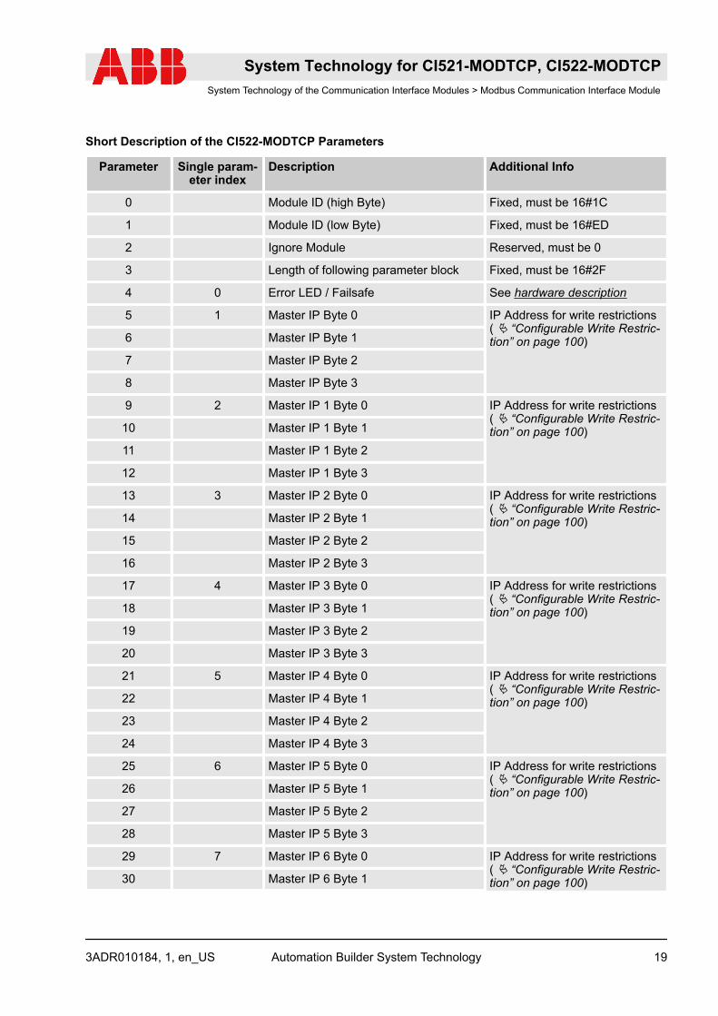
Short Description of the CI522-MODTCP Parameters
Parameter Single param-eter index
Description Additional Info
0 Module ID (high Byte) Fixed, must be 16#1C
1 Module ID (low Byte) Fixed, must be 16#ED
2 Ignore Module Reserved, must be 0
3 Length of following parameter block Fixed, must be 16#2F
4 0 Error LED / Failsafe See hardware description
5 1 Master IP Byte 0 IP Address for write restrictions( Ä “Configurable Write Restric-tion” on page 100)6 Master IP Byte 1
7 Master IP Byte 2
8 Master IP Byte 3
9 2 Master IP 1 Byte 0 IP Address for write restrictions( Ä “Configurable Write Restric-tion” on page 100)10 Master IP 1 Byte 1
11 Master IP 1 Byte 2
12 Master IP 1 Byte 3
13 3 Master IP 2 Byte 0 IP Address for write restrictions( Ä “Configurable Write Restric-tion” on page 100)14 Master IP 2 Byte 1
15 Master IP 2 Byte 2
16 Master IP 2 Byte 3
17 4 Master IP 3 Byte 0 IP Address for write restrictions( Ä “Configurable Write Restric-tion” on page 100)18 Master IP 3 Byte 1
19 Master IP 3 Byte 2
20 Master IP 3 Byte 3
21 5 Master IP 4 Byte 0 IP Address for write restrictions( Ä “Configurable Write Restric-tion” on page 100)22 Master IP 4 Byte 1
23 Master IP 4 Byte 2
24 Master IP 4 Byte 3
25 6 Master IP 5 Byte 0 IP Address for write restrictions( Ä “Configurable Write Restric-tion” on page 100)26 Master IP 5 Byte 1
27 Master IP 5 Byte 2
28 Master IP 5 Byte 3
29 7 Master IP 6 Byte 0 IP Address for write restrictions( Ä “Configurable Write Restric-tion” on page 100)30 Master IP 6 Byte 1
System Technology for CI521-MODTCP, CI522-MODTCPSystem Technology of the Communication Interface Modules > Modbus Communication Interface Module
3ADR010184, 1, en_US Automation Builder System Technology 19

Parameter Single param-eter index
Description Additional Info
31 Master IP 6 Byte 2
32 Master IP 6 Byte 3
33 8 Master IP 7 Byte 0 IP Address for write restrictions( Ä “Configurable Write Restric-tion” on page 100)34 Master IP 7 Byte 1
36 Master IP 7 Byte 2
36 Master IP 7 Byte 3
37 2 Timeout Timeout for bus supervision in10ms steps
if set to 0 no bus supervision isactive
38 3 (read only) I/O Mapping Structure See hardware description
39 4 Reserved Reserved, must be 0
40 5 Reserved
41 6 Reserved
42 7 Check supply See hardware description
43 8 Input delay
44 9 Fast counter See hardware description
46 10 Short circuit detection
46 11 Behavior binary outputs at com. fault
47 12 Substitute value binary outputs (highbyte)
48 Substitute value binary outputs (lowbyte)
49 13 Voltage feedback monitoring
50 14 Overvoltage monitoring
Parameters of Connected Expansion ModulesThe parameters of the connected expansion modules are represented as byte array (the parameters valid for“CPU” in the hardware description of the corresponding module are used):
System Technology for CI521-MODTCP, CI522-MODTCPSystem Technology of the Communication Interface Modules > Modbus Communication Interface Module
3ADR010184, 1, en_USAutomation Builder System Technology20
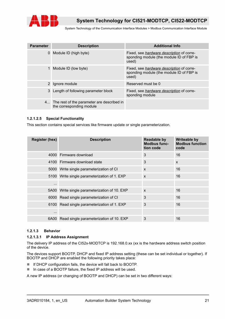
Parameter Description Additional Info
0 Module ID (high byte) Fixed, see hardware description of corre-sponding module (the module ID of FBP isused)
1 Module ID (low byte) Fixed, see hardware description of corre-sponding module (the module ID of FBP isused)
2 Ignore module Reserved must be 0
3 Length of following parameter block Fixed, see hardware description of corre-sponding module
4... The rest of the parameter are described inthe corresponding module
1.2.1.2.5 Special FunctionalityThis section contains special services like firmware update or single parameterization.
Register (hex) Description Readable byModbus func-tion code
Writeable byModbus functioncode
4000 Firmware download 3 16
4100 Firmware download state 3 x
5000 Write single parameterization of CI x 16
5100 Write single parameterization of 1. EXP x 16
...
5A00 Write single parameterization of 10. EXP x 16
6000 Read single parameterization of CI 3 16
6100 Read single parameterization of 1. EXP 3 16
...
6A00 Read single parameterization of 10. EXP 3 16
1.2.1.3 Behavior1.2.1.3.1 IP Address AssignmentThe delivery IP address of the CI52x-MODTCP is 192.168.0.xx (xx is the hardware address switch positionof the device.
The devices support BOOTP, DHCP and fixed IP address setting (these can be set individual or together). IfBOOTP and DHCP are enabled the following priority takes place:
n If DHCP configuration fails, the device will fall back to BOOTP.n In case of a BOOTP failure, the fixed IP address will be used.
A new IP address (or changing of BOOTP and DHCP) can be set in two different ways:
System Technology for CI521-MODTCP, CI522-MODTCPSystem Technology of the Communication Interface Modules > Modbus Communication Interface Module
3ADR010184, 1, en_US Automation Builder System Technology 21
n With the address switches of the corresponding modulen With the IP Configuration Tool
Using the Address SwitchesWith the address switches only the last byte of the IP address can be changed.
The IP address can only be set via the address switches in case of factory default or in case of the last byteof the IP address is set to zero with the IP Configuration Tool. The not allowed IP addresses are mapped asfollowed:
n Address switch position 255 is mapped to fixed IP 192.168.0.254 independent of other stored settings(by IP Configuration Tool).This is a backup so the module can always get a valid IP address and can be configured by the IP Con-figuration Tool.
n Address switch position 0 is mapped to last byte equal 1 and DHCP enabled.
Using the IP Configuration ToolWith the IP Configuration Tool a network scan can be executed, and the found devices can be assigned withnew settings, e.g. enable BOOTP or DHCP and set a new fixed IP. If the last byte of the IP address of theCI52x-MODTCP devices is set to 0 with the IP Configuration Tool the address switch position is used instead(see Ä Chapter 1.2.1.3.1.1 “Using the Address Switches” on page 98).
1.2.1.3.2 ParameterizationThe parameterization is done via the corresponding registers explained in the Modbus TCP registersÄ Chapter 1.2.1.2.4 “Parameter Data (Acyclic Data)” on page 91.
In addition to that the parameters can be directly transferred via Automation Builder (see documentation ofAutomation Builder for that).
There are two different parameter sections with different behaviour.
Actual used parametersAfter startup this section contains the following data:
n Default parameters (only module id and parameter length set all others zero) if no valid stored parame-ters are available (no or invalid parameters stored).
n Actual used / stored parameters if valid parameters are stored nonvolatile.
These parameters can be read out and changed by reading or writing of the corresponding registers, but willnot be used automatically after writing them, the use of new written parameters has to be triggered by writingthe parameter control word with the corresponding bits set (see below).
Stored parametersThis section always contains a copy of the nonvolatile stored parameters, if no parameters are stored nonvo-latile this sections will be 0.
Controlword/statusword parameterThis parameter can be used to trigger and save new parameters.
The direction of the first 8 bit is client to server (master to slave). The direction of the second 8 bits is serverto client (slave to master).
System Technology for CI521-MODTCP, CI522-MODTCPSystem Technology of the Communication Interface Modules > Modbus Communication Interface Module
3ADR010184, 1, en_USAutomation Builder System Technology22

Bit Meaning Description
0 Use parameters / start param-eterization
If this bit is set the CI Device starts the parameterization with theparameters in the actual parameters registers.
1 Store parameters volatile If this bit is set the CI device will use the parameters temporarily,which means after a bus error detection and reconnection theparameters will be used again.
This bit should always be set.This bit is only evaluated when bit 0 is set.
2 Store parameters nonvolatile If this bit is set the CI device will store the parameters nonvola-tile, which means after a power cycle the stored parameter datawill be used again.
This bit is only evaluated when bit 0 is set.
3 Reserved
4 Delete nonvolatile storedparameters
If this bit is set the CI device will delete its nonvolatile storedparameters.
This bit is only evaluated when bit 0 is set.
5 Ignore parameter error fornonvolatile parameter storage
If this bit is set a parameter error during nonvolatile storage ofparameters will be ignored, and the parameters will be stored.
This bit can only be set in combination with bit 0 and bit 2.
6 Reserved
7 Reserved
8 New diagnosis available The device will set this bit if new diagnosis data are available inthe diagnosis data section.
9 New parameters available The device will set this bit if new parameters are available in theactual parameter data section and these were not activated bysetting bit 0 in the control word.
10...15 Reserved
1.2.1.3.3 Cyclic I/O Data ExchangeThe I/O data can be exchanged cyclic by the master by reading, writing the corresponding registers.
I/O data exchange is only possible after successful parameterization of the device.
For writing of outputs bus failure detection can be activated by setting the corresponding parameter. Thisbus failure detection is described in the following chapter.
Bus Failure DetectionIf the parameter “ “timeout” ” in the module parameters of the CI52x-MODTCP is set, the module will super-vise the Modbus TCP "write telegrams".
After the first "write telegram" the bus will be supervised. If no new "write telegram" arrives at the CI52x-MODTCP within the configured time, the module will detect a bus failure and switch off its outputs or switchthem to the configured failsafe state (see module parameter “Failsafe CI521” and “Failsafe CI522” fordetails).
System Technology for CI521-MODTCP, CI522-MODTCPSystem Technology of the Communication Interface Modules > Modbus Communication Interface Module
3ADR010184, 1, en_US Automation Builder System Technology 23

Configurable Write RestrictionWith the module parameters “Master IP”- “Master IP 7” it is possible to set write restrictions on the CI52x-MODTCP device.
If none of the parameters is set, all masters / clients in the network have read and write rights on the CI52x-MODTCP device and its connected expansion modules.
If at least one parameter is set only the configured masters / clients have write rights on the CI52x-MODTCPdevice.
All other masters / clients still have read access to the CI52x-MODTCP device.
1.2.1.3.4 Diagnosis behaviorEach diagnosis message signals if this error is coming or going , so it is possible to create a list in the masterof actual pending diagnosis.
Diagnosis messages will be transferred again after a bus failure detection and reconnection.
Diagnosis messages can be read out with function code 3,4,23. Function codes 3 and 4 can always read outdiagnosis messages, function code 23 can only read out after successful parameterization of the device. Seealso table Ä Chapter 1.2.1.2.3.2 “Diagnosis Data” on page 85.
1.2.1.3.5 Single ParameterizationThe single parameterization services can be used to read or write parameters during runtime of devicewithout the need of triggering a new parameterization process.
For indexes used for single parameterization services see parameter lists in section Modbus TCP registersof this document.
The read and write parameterization services are explained below, for each module (CI52x-MODTCP andconnected expansion modules) a different section for read and write is defined see chapter Modbus TCPregisters in this document). Both services are using the following data structure:
The length of the read / write service depends on the count of parameters that should be transferred (length= 4+ count*8).
Reading of Single ParametersThe read single parameterization works in two steps:
System Technology for CI521-MODTCP, CI522-MODTCPSystem Technology of the Communication Interface Modules > Modbus Communication Interface Module
3ADR010184, 1, en_USAutomation Builder System Technology24
n Writing of a request list containing the indexes that should be read using the structure explained above.Only CNT and PARA_IDX has to be set.Up to 5 parameters can be requested with one telegram.The length of the write service depends on the count of parameters that should be transferred (length =4+ count*8).
n Reading of the parameters list with the same length then the previous write request.If the internal reading process inside the CI52x-MODTCP device is done the data will be read out.If the internal reading process inside the CI52x-MODTCP device is not yet finished the read service willbe rejected with Modbus TCP exception code 6 (device busy).
Writing of Single ParametersFor writing of single parameters only one step is necessary, the parameters are transferred with one writerequest using the structure described above.
The length of the write service depends on the count of parameters that should be transferred (length = 4+count*8).
In case of write of single parameters the following values have to be set:
n CNT: number of parameters to be setn And for each parameter:
Parameter indexParameter lengthNew parameter value
Written single parameters are not stored volatile and not stored nonvolatile. That means after a bus recon-nection or power cycle the written parameters will be discarded.
1.2.1.4 Commissioning ExampleSet IP Address:
n The setting of the IP address is the first step to integrate the CI52x-MODTCP devices into a runningsystem.
n The setting of the IP address of the CI52x-MODTCP devices is described in the chapter Ä Chapter1.2.1.3.1 “IP Address Assignment” on page 97 in this document.
Set Parameters (optional read parameters):
n The second step in configuring the CI52x-MODTCP devices is to set the module and channel parame-ters.
n A read of parameters is optional but can be used the get the module IDs and the parameter length.n The reading and or writing of parameters is described in chapter Ä Chapter 1.2.1.3.2 “Parameterization”
on page 98.
Set Control Word:
n After setting the parameter data these have to be activated by writing the control word.n The meaning and usage of the control word is described in chapter Ä Chapter 1.2.1.3.2 “Parameteriza-
tion” on page 98.
Exchange data:
n After setting and activating the parameters the CI52x-MODTCP device is ready for data exchange.n The registers for data exchange are described in chapter Ä Chapter 1.2.1.2.3 “I/O / Process Data and
Diagnosis Section (Cyclic Data)” on page 82.
System Technology for CI521-MODTCP, CI522-MODTCPSystem Technology of the Communication Interface Modules > Modbus Communication Interface Module
3ADR010184, 1, en_US Automation Builder System Technology 25
1.2.1.5 Hot SwapWith hot swap for AC500 and S500 it is possible to exchange expansion modules (with same type) duringruntime.
System Technology for CI521-MODTCP, CI522-MODTCPSystem Technology of the Communication Interface Modules > Modbus Communication Interface Module
3ADR010184, 1, en_USAutomation Builder System Technology26

1.2.1.5.1 Preconditions for Using Hot SwapHot SwapH = Hot swap
Hot swap
Preconditions for hot swapping I/O modules:
– Hot-swappable terminal units have the appendix TU5xx-H.– I/O modules as of index F0.– Communication interface modules CI5xx as of index F0.
The index of the module is in the right corner of the label.
NOTICE!
Risk of damage to I/O modules!Modules with index below F0 can be damaged when inserted or removed from the terminal unit in apowered system.
Hot swapping is only allowed for I/O modules.
Processor modules and communication interface modules must not be removed or inserted duringoperation.
System Technology for CI521-MODTCP, CI522-MODTCPSystem Technology of the Communication Interface Modules > Modbus Communication Interface Module
3ADR010184, 1, en_US Automation Builder System Technology 27
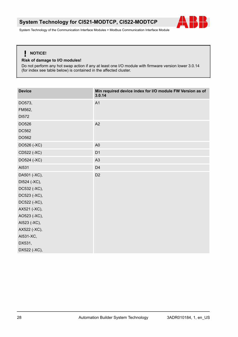
NOTICE!
Risk of damage to I/O modules!Do not perform any hot swap action if any at least one I/O module with firmware version lower 3.0.14(for index see table below) is contained in the affected cluster.
Device Min required device index for I/O module FW Version as of3.0.14
DO573,
FM562,
DI572
A1
DO526
DC562
DO562
A2
DO526 (-XC) A0
CD522 (-XC) D1
DO524 (-XC) A3
AI531 D4
DA501 (-XC),
DI524 (-XC),
DC532 (-XC),
DC523 (-XC),
DC522 (-XC),
AX521 (-XC),
AO523 (-XC),
AI523 (-XC),
AX522 (-XC),
AI531-XC,
DX531,
DX522 (-XC),
D2
System Technology for CI521-MODTCP, CI522-MODTCPSystem Technology of the Communication Interface Modules > Modbus Communication Interface Module
3ADR010184, 1, en_USAutomation Builder System Technology28
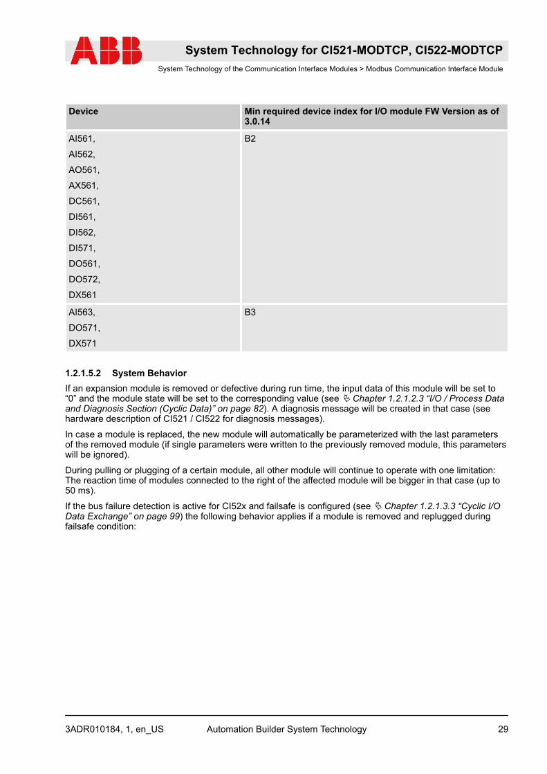
Device Min required device index for I/O module FW Version as of3.0.14
AI561,
AI562,
AO561,
AX561,
DC561,
DI561,
DI562,
DI571,
DO561,
DO572,
DX561
B2
AI563,
DO571,
DX571
B3
1.2.1.5.2 System BehaviorIf an expansion module is removed or defective during run time, the input data of this module will be set to“0” and the module state will be set to the corresponding value (see Ä Chapter 1.2.1.2.3 “I/O / Process Dataand Diagnosis Section (Cyclic Data)” on page 82). A diagnosis message will be created in that case (seehardware description of CI521 / CI522 for diagnosis messages).
In case a module is replaced, the new module will automatically be parameterized with the last parametersof the removed module (if single parameters were written to the previously removed module, this parameterswill be ignored).
During pulling or plugging of a certain module, all other module will continue to operate with one limitation:The reaction time of modules connected to the right of the affected module will be bigger in that case (up to50 ms).
If the bus failure detection is active for CI52x and failsafe is configured (see Ä Chapter 1.2.1.3.3 “Cyclic I/OData Exchange” on page 99) the following behavior applies if a module is removed and replugged duringfailsafe condition:
System Technology for CI521-MODTCP, CI522-MODTCPSystem Technology of the Communication Interface Modules > Modbus Communication Interface Module
3ADR010184, 1, en_US Automation Builder System Technology 29
n Last value configured for output:– After a bus failure is detected, failsafe will be activated and the output will remain at its last value.– If the module is removed and plugged again, the output will remain off, and not be kept its last value,
as the last value of the new module is “0” in that case.n Substitute value configured for output:
– After a bus failure is detected, failsafe will be activated and the output will be according to the config-ured substitute value.
– If the module is removed and plugged again now, the output will be set according to the configuredsubstitute value again.
n Substitute value for x seconds configured for output:– After a bus failure is detected, failsafe will be activated and the output will be according to the config-
ured substitute value for the configured time.– If the module is removed and plugged again now, the output will be set according to the configured
substitute value again, and the configured time starts again.
1.2.1.5.3 Mandatory Rules for Hot SwappingMandatory rules for hot swapping:
n Between two pull and / or plug operations of I/O modules a pause of at least 1 second must be observed.– That means if a module is pulled or plugged there has to be at least a break of 1 second before the
next module is pulled or plugged.n At boot up of CI52x all configured expansion modules have to be physically available.
– Start up with missing modules is not supported.n As there is no special configuration available for hot swap terminal units, there is no possibility for the
CI52x to generate diagnosis messages if there is no hot swap terminal unit available.– This has to be checked by application:
Best way for checking if a hot swap terminal unit is available or not, is reading out the commondevice information registers (see Ä Chapter 1.2.1.2.2 “Information Data Section (Acyclic Data)”on page 79). If the CI52x rejects this read out the CI52x doesn’t support hot swap at all.
System Technology for CI521-MODTCP, CI522-MODTCPSystem Technology of the Communication Interface Modules > Modbus Communication Interface Module
3ADR010184, 1, en_USAutomation Builder System Technology30