melting point apparatus - stuart equipment | hotplates | … · · 2013-05-15melting point...
TRANSCRIPT
Version 1.1
heating rate ºC/min10
Melting PointApparatus SMP11
Instructions for useMode d’emploiIstruzioni per usoInstrucciones de funcionamientoGebrauchsanweisung
Scientific

English
heating rate ºC/min10
Capillary tube
Heating controller
Thermometersupport
Thermometer
IEC connector
Lens
Fig 1
MELTING POINTAPPARATUSSMP11
Thank you for purchasing this Stuart product.To get the best performance from theequipment, and for your own safety, please readthese instructions carefully before use. (For anillustration of the controls, see Fig 1).
Safety advice before useThis equipment is designed to operate under thefollowing conditions: -❖ For indoor use only❖ Use in a well ventilated area❖ Ambient temperature +5°C to +40°C❖ Altitude to 2000m❖ Relative humidity not exceeding 80%❖ Mains supply fluctuation not >10%❖ Overvoltage category II IEC60364-4-443❖ Pollution degree 2 IEC664❖ Use with a minimum distance all around of
200mm from walls or other items
If the equipment is not used in the mannerdescribed in this manual the protectionprovided by the equipment may beimpaired.
1
Electrical installationTHIS EQUIPMENT MUST BE EARTHED
Before connection please ensure that the linesupply corresponds to that stated on the ratinglabel. Power consumption is 50W.
There is an IEC socket at the rear on the lefthand side of the instrument for connection tothe mains supply, (see figure 1). The unit issupplied with two mains leads fitted with IECplugs for connection to the instrument. One hasa U.K. 3 pin plug and the other has a 2 pin“Shuko” plug for connection to the mainssupply. Choose the lead appropriate for yourelectrical installation and discard the other.
Should neither lead be suitable you shouldobtain a moulded lead locally. If this is notpossible, take the lead with the U.K. plug andreplace the plug with a suitable alternative. Seethe enclosed instruction sheet for advice on howto carry out this procedure.
Should the mains lead require replacement acable of 1mm2 of harmonized code H05V V-Fconnected to an IEC 320 plug should be used.
N.B. The UK mains lead is protected by a 10Afuse mounted in the plug top.
The mains lead should be connected to theinstrument BEFORE connection to the mainssupply.
IF IN DOUBT CONSULT A QUALIFIEDELECTRICIAN
General descriptionThe sample for the melting point test is placed ina capillary tube and inserted in to the aluminiumblock inside the heater. Using the manuallyadjustable heating rate, the SMP11 will rapidlyheat samples up to 20°C per minute to the melttemperature and up to the maximumtemperature of 250°C. An accurate reading towithin 1°C of the melt temperature can beachieved by using a slower heating rate ofbetween 1 and 10°C per minute. The sample isobserved through the magnifying lens until themelt occurs and the melt temperature read fromthe thermometer.
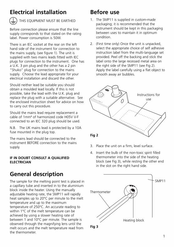
Before use1. The SMP11 is supplied in custom-made
packaging; it is recommended that theinstrument should be kept in this packagingbetween uses to maintain it in optimumcondition.
2. (First time only) Once the unit is unpacked,select the appropriate choice of self adhesiveinstruction label from the multi-language setprovided. Peel off the backing and stick thelabel onto the large recessed metal area onthe right side of the SMP11 (see Fig 2).Apply the label carefully using a flat object tosmooth away air bubbles.
Instructions foruse
Fig 2
Fig 3
3. Place the unit on a firm, level surface.
4. Insert the bulb of the non-toxic spirit filledthermometer into the side of the heatingblock (see Fig 3), while resting the other endin the slot on the right hand side.
Thermometer
Heating block
SMP11

Measuring a melting pointN.B. If the unit has been used recently the blockmay be too hot for your sample. If this is the caseturn the apparatus off and allow the unit to coolbefore proceeding. An optional brass cold finger(ref. SMP1/2) can be inserted into thethermometer hole; this has the effect of drawingheat out of the heating block and so considerablyreduces the cooling time.
1. The SMP11 is supplied with a pack of 1.9mmopen-ended capillary tubes. It is recommendedthat one end of the tubes should be sealedwith a Bunsen burner flame, by a fully trainedperson, prior to use. Alternatively a pack ofcapillary tubes that have been sealed on oneend can be purchased from your Stuartstockist (ref. SMP10/1).
2. Place a small amount of your powderedsample into the end of a 1.9mm diameterglass capillary tube.
3. Insert the capillary tube into the side of theheating block via the holes provided (see Fig4). A maximum of 3 capillary tubes can beinserted at any one time.
4. Look down the lens and position the tube sothat the sample can be observed clearly (see Fig 5).
2
Fig 4Fig 6
Thermometer
Heating block
Thermometer
Capillary tube
Capillary tube
5. It is assumed that the approximate meltingpoint range is known, if not a rough run maybe required to gauge the approximate range.
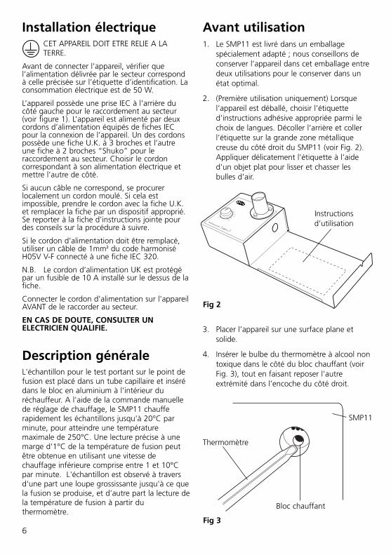
6. In order to achieve a fast and accuratemelting point range it is important to use arapid heating rate as the sample heats upfrom ambient and a much reduced heatingrate as the sample approaches melt, see Fig6 for an ideal heating curve for a samplewith a melting point of 240°C.
Fig 5
0
100
150
200
250
300
50
0 2 4 6 8 10 12 14 16 18 20 22 24 26
Time (min)
Tem
per
atu
re °
C
Max 10°C/min 1°C/min
Dial settings
Block temperature
Melting point
Ideal heating curve
7. Connect to the mains electricity supply.
8. Start by heating the sample at the maximumrate by setting the heating controller to max.
Lens
Caution: The heating block may be HOT.

9. Once the thermometer reaches 60% of theexpected melting point the heating controllershould be reduced to 10°C/min, by turningthe heating controller anti-clockwise.
10. Continue to reduce the heating controller sothat it is on 1°C/min when the sample iswithin 15°C of the expected melt.
11. Observe the melt through the eyepiece,while recording the temperature on thethermometer; make a note of the melttemperature.
12. Turn off to begin cooling, or insert theaccessory brass insert to speed up cooling.
Cleaning & ServicingWARNING: Ensure the unit isdisconnected from the mains electricitysupply and allowed to cool beforeattempting any cleaning or servicing.
CleaningPeriodically clean the instrument using a dampcloth and mild detergent solution. Do not useharsh or abrasive cleaning agents.
In the event of any breakage of the thermometerbulb or capillary tubes disconnect the unit fromthe mains supply. Any debris can be removedsimply by unscrewing the dome nuts holding the
3
lens and then lifting the lens out (see Fig 7). Theinstrument can then be turned upside down sothat any debris falls out. Once the lens has beenremoved the chamber can be cleaned with adamp cloth or a soft brush.
ServicingThis unit does NOT require routine servicing.
RepairsThere are no user replacement parts on thisinstrument. If this unit were to stop working ormalfunction in any way, only suitably qualifiedpersonnel should investigate the problem. Priorto any internal repairs being undertaken aservice manual should be requested from theTechnical Service Department of BarloworldScientific Ltd. quoting both the model and serialnumber of your product.
NB: Fuses are mounted in both the live andneutral line.
Only spare parts supplied or specified byBarloworld Scientific Ltd. or its agents should beused. Fitting of non-approved parts may affectthe performance and safety features designedinto the instrument.
If in any doubt, please contact the TechnicalDept. of Barloworld Scientific or the point ofsale.
Barloworld Scientific Ltd. Stone, Staffordshire ST15 0SA United KingdomTel: +44 (0) 1785 812121 Fax: +44 (0) 1785 813748 e-mail [email protected]
Fig 7
Lens
Dome nuts
Heatingcontroller

4
WarrantyBarloworld Scientific Ltd warrants this instrumentto be free from defects in material andworkmanship, when used under normallaboratory conditions, for a period of three (3)years. In the event of a justified claim,Barloworld Scientific will replace any defectivecomponent or replace the unit free of charge.
This warranty does NOT apply if damage iscaused by fire, accident, misuse, neglect,incorrect adjustment or repair, damage causedby installation, adaptation, modification, fittingof non-approved parts or repair by unauthorizedpersonnel.
Technical Specification
Number of samples Three
Temperature range Ambient to 250°C
Heating rates 1°C to a max of 20°C/min
Dimensions (WxDxH) 370 x 140 x 110 mm
Net weight 1.7 Kg
Electrical supply
SMP11 230V, 50/60Hz, 50W
SMP11/100V/60 100V, 50/60Hz, 50W
SMP11/120V/60 120V, 50/60Hz, 50W
Spares / Accessories
SMP11/1 Spare spirit filled thermometer, 0 to 250°C.
SMP1/2 Brass cooling plug
SMP1/4 Melting point tubes (open both ends)
SMP2/1 Melting point tubes (sealed both ends)
SMP10/1 Melting point tubes (sealed a one end)

5
Français
heating rate ºC/min10
Tube capillaire
Régulation duchauffage
Support duthermomètre
Thermomètre
Connecteur IEC
Loupe
Fig 1
APPAREIL A POINT DEFUSIONSMP11
Merci d’avoir acheté ce produit Stuart. Pour tirerles meilleures performances de cet appareil, etpour votre propre sécurité, veuillez lireattentivement ces instructions avant utilisation(pour une illustration des commandes, voir Fig.1).
Conseils de sécurité avantutilisationCet appareil est conçu pour fonctionner dans lesconditions suivantes : -❖ Utilisation uniquement en intérieur❖ Utilisation dans un endroit bien ventilé❖ Température ambiante +5°C à +40°C❖ Altitude jusqu’à 2000 m❖ Humidité relative ne dépassant pas 80%❖ Variation du secteur ne dépassant pas 10%❖ Catégorie surtension II IEC60364-4-443❖ Degré de pollution 2 IEC664❖ Utilisation à une distance minimale de 200
mm de toute paroi ou autre élément
Toute utilisation de cet appareil d’unefaçon non décrite dans ce manuel peutaltérer la protection intrinsèque del’appareil.
6
Installation électriqueCET APPAREIL DOIT ETRE RELIE A LATERRE.
Avant de connecter l’appareil, vérifier quel’alimentation délivrée par le secteur correspondà celle précisée sur l’étiquette d’identification. Laconsommation électrique est de 50 W.
L’appareil possède une prise IEC à l’arrière ducôté gauche pour le raccordement au secteur(voir figure 1). L’appareil est alimenté par deuxcordons d’alimentation équipés de fiches IECpour la connexion de l’appareil. Un des cordonspossède une fiche U.K. à 3 broches et l’autreune fiche à 2 broches “Shuko” pour leraccordement au secteur. Choisir le cordoncorrespondant à son alimentation électrique etmettre l’autre de côté.
Si aucun câble ne correspond, se procurerlocalement un cordon moulé. Si cela estimpossible, prendre le cordon avec la fiche U.K.et remplacer la fiche par un dispositif approprié.Se reporter à la fiche d’instructions jointe pourdes conseils sur la procédure à suivre.
Si le cordon d’alimentation doit être remplacé,utiliser un câble de 1mm2 du code harmoniséH05V V-F connecté à une fiche IEC 320.
N.B. Le cordon d’alimentation UK est protégépar un fusible de 10 A installé sur le dessus de lafiche.
Connecter le cordon d’alimentation sur l’appareilAVANT de le raccorder au secteur.
EN CAS DE DOUTE, CONSULTER UNELECTRICIEN QUALIFIE.
Description généraleL'échantillon pour le test portant sur le point defusion est placé dans un tube capillaire et insérédans le bloc en aluminium à l'intérieur duréchauffeur. A l'aide de la commande manuellede réglage de chauffage, le SMP11 chaufferapidement les échantillons jusqu'à 20°C parminute, pour atteindre une températuremaximale de 250°C. Une lecture précise à unemarge d'1°C de la température de fusion peutêtre obtenue en utilisant une vitesse dechauffage inférieure comprise entre 1 et 10°Cpar minute. L'échantillon est observé à traversd'une part une loupe grossissante jusqu'à ce quela fusion se produise, et d'autre part la lecture dela température de fusion à partir duthermomètre.
Instructionsd’utilisation
Fig 2
Fig 3
Thermomètre
Bloc chauffant
SMP11
Avant utilisation1. Le SMP11 est livré dans un emballage
spécialement adapté ; nous conseillons deconserver l’appareil dans cet emballage entredeux utilisations pour le conserver dans unétat optimal.
2. (Première utilisation uniquement) Lorsquel’appareil est déballé, choisir l’étiquetted’instructions adhésive appropriée parmi lechoix de langues. Décoller l’arrière et collerl’étiquette sur la grande zone métalliquecreuse du côté droit du SMP11 (voir Fig. 2).Appliquer délicatement l’étiquette à l’aided’un objet plat pour lisser et chasser lesbulles d’air.
3. Placer l’appareil sur une surface plane etsolide.
4. Insérer le bulbe du thermomètre à alcool nontoxique dans le côté du bloc chauffant (voirFig. 3), tout en faisant reposer l’autreextrémité dans l’encoche du côté droit.

7
Mesure d’un point defusionN.B. Si l’appareil a été utilisé récemment, le blocpeut être trop chaud pour l’échantillon. Dans cecas, éteindre l’appareil et le laisser refroidir avantde continuer. Un cylindre de refroidissement enlaiton optionnel (réf. SMP1/2) peut être insérédans le trou du thermomètre ; ceci a pour effetd’extraire la chaleur hors du bloc chauffant et deraccourcir considérablement le temps derefroidissement.
1. Le SMP11 est livré avec un paquet de tubescapillaire de 1,9 mm à extrémités ouvertes. Ilest conseillé de faire sceller par une personneformée une des extrémités des tubes à l’aided’un bec Bunsen avant utilisation. Il estégalement possible d’acheter un paquet detubes capillaires déjà fermés à une extrémitéauprès d’un distributeur de Stuart (réf.SMP10/1).
2. Placer une petite quantité de l’échantillon enpoudre dans l’extrémité du tube capillaire enverre de 1,9 mm de diamètre.
3. Insérer le capillaire dans le côté du blocchauffant dans les trous prévus (voir Fig. 4).3 capillaire maximum peuvent être insérés enune seule fois.
Fig 4Fig 6
Thermomètre
ThermomètreLoupe
Tube capillaire
Tube capillaire
Fig 5
0
100
150
200
250
300
50
0 2 4 6 8 10 12 14 16 18 20 22 24 26
Temps (min)
Tem
pér
atu
re °
C
Max 10°C/min 1°C/min
Block température
Point de fusion
Courbe de chauffage idéale
4. Observer à travers la loupe et positionner letube pour que l’échantillon puissent êtreclairement observé (voir Fig. 5).
5. La plage approximative du point de fusionest supposée connue; sinon, un test rapidepeut être nécessaire pour estimer la plageapproximative.
6. Pour atteindre une plage de point de fusionrapide et précise, il est important d’utiliserune vitesse de montée en températurerapide lorsque l’échantillon est chauffé àpartir de la température ambiante, et unevitesse plus faible lorsque l’échantillonapproche de la fusion. Voir Fig. 6 pour unecourbe de chauffage idéale pour unéchantillon de point de fusion de 240°C.
7. Raccorder l’appareil au secteur.
8. Démarrer en chauffant l’échantillon à lapuissance maximale en réglant le régulateurde chauffage sur max.
Block chauffant
Attention: Le bloc de chauffage peutêtre CHAUD

9. Lorsque le thermomètre atteint 60% dupoint de fusion estimé, réduire le régulateurde chauffage sur 10°C/min, en tournant lerégulateur de chauffage dans le sens anti-horaire.
10. Continuer à réduire le régulateur jusqu’à cequ’il atteigne 1°C/min lorsque l’échantillonest à 15°C de sa fusion attendue.
11. Contempler la fusion à travers l’oculaire, touten observant la température affichée par lethermomètre ; noter la température defusion.
12. Eteindre pour commencer le refroidissement,ou insérer l'accessoire en laiton pouraccélérer le refroidissement.
Nettoyage et entretienATTENTION : vérifier que l’appareil estdéconnecté du secteur et le laisser refroidiravant d’entreprendre toute action denettoyage ou d’entretien.
NettoyageNettoyer périodiquement l’appareil à l’aide d’unchiffon humide et d’une solution de détergentdoux. Ne pas utiliser de nettoyants durs ouabrasifs.
En cas de bris du bulbe du thermomètre ou detubes capillaires, déconnecter l’appareil dusecteur. Retirer simplement tous les débris endévissant les écrous en dôme maintenant laloupe et en soulevant la loupe pour la retirer(voir Fig. 7). L’appareil peut à présent êtreretourné pour faire tomber tous les débris en-dehors. Une fois la loupe retirée, il est possiblede nettoyer la chambre avec un chiffon humideou une brosse souple.
EntretienCet appareil ne nécessite PAS d’entretien deroutine.
RéparationsCet appareil ne possède aucune pièceremplaçable par l’utilisateur. Si cet appareil nefonctionne plus ou mal d’une façon ou d’uneautre, seules des personnes convenablementqualifiées sont autorisées à rechercher leproblème. Avant d’entreprendre toute réparationinterne, demander un manuel d’entretien auService Technique de Barloworld Scientific Ltd. enprécisant le modèle et le numéro de série duproduit.
NB : les fusibles sont installés sur la ligne soustension et le neutre.
Utiliser uniquement les pièces de rechangefournies ou spécifiées par Barloworld ScientificLtd. ou ses agents. L’installation de pièces nonagréées peut affecter les performances et lasécurité intrinsèques de l’appareil.
En cas de doute, contacter le Service Techniquede Barloworld Scientific ou le point de vente.
Barloworld Scientific France SASZI du Rocher Vert - BP 7977793 Nemours Cedex FranceTél: +33 1 64 45 13 13 Fax: +33 1 64 45 13 00 e-mail: [email protected]
8
Fig 7
Loupe
Ecrous endôme
Régulateurdechauffage

GarantieBarloworld Scientific Ltd. garantit que cetappareil est exempt de tout de défaut dematériaux et de transformation, s’il est utilisédans les conditions normales de laboratoire,pendant une période de trois (3) ans. En cas dedemande justifiée, Barloworld Scientificremplacera tout composant défectueux ouremplacera l’appareil gratuitement.
Cette garantie ne s’applique PAS si lesdommages sont le résultat d’un incendie,accident, mauvaise utilisation, négligence,réglage incorrect ou réparation, si les dommagessont causés par une mauvaise installation,adaptation, modification, mise en place depièces non agréées ou réparation par unepersonne non habilitée.
Spécifications techniquesNombre d’échantillons Trois
Gamme de température Ambiante à 250°C
Montée en température 1°C jusqu'à un maximumde 20°C/min.
Dimensions (LxPxH) 370 x 140 x 110 mm
Poids net 1,7 Kg
Alimentation
SMP11 230 V, 50/60 Hz, 50W
SMP11/100V/60 100 V, 50/60 Hz, 50W
SMP11/120V/60 120 V, 50/60 Hz, 50W
Pièces de rechange / Accessoires
SMP11/1 Thermomètre à alcool de rechange, 0 à 250°C
SMP1/2 Cylindre de refroidissement en laiton
SMP1/4 Tubes pour point de fusion (ouverts aux deux extrémités)
SMP2/1 Tubes pour point de fusion (fermés aux deux extrémités)
SMP10/1 Tubes pour point de fusion (fermés à une extrémité)
9

10
Italiano
heating rate ºC/min10
Tubo capillare
Regolazioneriscaldamento
Supportotermometro
Termometro
Connettore IEC
Oculare
Fig 1
APPARECCHIO PER PUNTODI FUSIONESMP11
Congratulazioni per l’acquisto di questo prodottoStuart. Per ottenere le migliori prestazioni daquesto apparecchio e per garantire la sicurezzadell’operatore, si consiglia di leggereattentamente le istruzioni prima dell’uso. (I componenti sono illustrati in Fig. 1)
Avvertenze di sicurezzaprima dell’usoQuesto prodotto è stato progettato per operarenelle seguenti condizioni: -
❖ Da utilizzare soltanto in ambienti chiusi❖ Utilizzare in ambienti ben ventilati❖ Temperatura ambiente da +5°C a +40°C❖ Altitudine fino a 2000m❖ Umidità relativa non superiore a 80%❖ Oscillazioni di tensione di alimentazione non
superiori a 10%❖ Categoria di sovratensione II IEC60364-4-443❖ Livello di inquinamento 2 IEC664❖ Utilizzare a una distanza minima di 200 mm
da pareti o altri oggetti su tutti i lati.
L’utilizzo dell’apparecchio in manierediverse da quelle descritte nel presentemanuale può compromettere le misure diprotezione adottate.

Installazione elettricaQUESTO APPARECCHIO DEVE ESSERECOLLEGATO A TERRA
Prima di procedere con il collegamento, verificareche l’alimentazione elettrica di rete corrispondaai valori prescritti nella targhetta datidell’apparecchio. Potenza assorbita: 50W.
Sul lato posteriore sinistro dell’apparecchio èpresente una presa IEC per il collegamentoall’alimentazione elettrica di rete (v. Fig. 1).L’apparecchio è fornito con due cavi dialimentazione di rete dotati di spine a normaIEC. Un cavo è dotato di spina GB a 3 spinotti el’altro è dotato di una spina di tipo Shuko a 2spinotti, per il collegamento all’alimentazione direte. Scegliere il cavo adatto alla propriasituazione e smaltire l’altro cavo.
Nel caso che nessuno dei cavi sia adatto,ottenere localmente una spina adatta di tipotermofuso. Se questa soluzione non dovesseessere possibile, sostituire la spina sul cavo ditipo britannico con una spina adatta alle proprieesigenze. Per informazioni su come eseguirequesta procedura, fare riferimento al foglio diistruzioni allegato.
Nel caso sia necessaria la sostituzione del cavo direte, utilizzare cavo da 1mm2 codice armonizzatoH05V V-F con una spina IEC 320.
N.B. Nel Regno Unito, la spina di alimentazione èprotetta con un fusibile da 10A, montatoall’interno della spina stessa.
Collegare sempre il cavo di alimentazioneall’apparecchio PRIMA di inserire la spina nellapresa di corrente di rete.
IN CASO DI DUBBI, RIVOLGERSI A UNELETTRICISTA QUALIFICATO
GeneralitàIl campione per la determinazione del punto difusione viene collocato all'interno di un tubocapillare e inserito nel blocchetto in alluminioall'interno del riscaldatore. Grazie allaregolazione manuale della rampa di incrementodi temperatura, il modello SMP11 può riscaldare
rapidamente il campione fino a raggiungere ilpunto di fusione, con tassi di incremento ditemperatura fino a 20 °C al minuto e unatemperatura massima di 250 °C. Una misuraaccurata della temperatura di fusione, con unaprecisione di 1 °C, può essere ottenutautilizzando un tasso di incremento dellatemperatura più lento, compreso fra 1 e 10 °C alminuto. Il campione viene osservato tramite illentino di ingrandimento. Al verificarsi dellafusione, la temperatura potrà essere lettasull'apposito termometro.
Prima dell’uso1. Il modello SMP11 è fornito in un imballo
specifico. Si raccomanda di conservare lostrumento in questo imballo quando non inuso per mantenerlo in condizioni ottimali.
2. (Solo primo utilizzo) Dopo aver disimballatol’apparecchio selezionare l’etichetta diistruzioni adesiva desiderata dal setmultilingua fornito. Rimuovere il dorso diprotezione e applicare l’etichetta sull’areametallica incavata sul lato destro dellostrumento (v. Fig. 2). Applicare l’etichetta conattenzione, utilizzando un oggetto piatto pereliminare eventuali bolle d’aria.
11
Istruzioni per uso
Fig 2
3. Collocare l’apparecchio su di una superficiepiana e robusta.
4. Inserire il bulbo del termometro ad alcoolnon tossico nel foro ricavato sul lato delblocchetto di riscaldamento (v. Fig. 3) eappoggiarne l’altra estremità nellascanalatura sulla destra dell’apparecchio.

12
Fig 3
Termometro
Blocchetto diriscaldamento
SMP11
Misura del punto difusioneN.B. Se l’apparecchio è stato appena utilizzato, latemperatura del blocchetto può essere troppoelevata per il campione da misurare. In questocaso, spegnere l’apparecchio e attenderne ilraffreddamento prima di procedere con lamisura. Eventualmente, inserire l’appositabarretta in ottone (accessorio opzionale rif.SMP1/2) nel foro del termometro per facilitarel’estrazione di calore dal blocchetto diriscaldamento e accelerare notevolmente iltempo necessario per il raffreddamento.
1. L’apparecchio SMP11 è fornito con unpacchetto di tubi capillari da 1,9 mm con leestremità aperte. Si raccomanda di sigillareun’estremità dei tubi utilizzando un beccoBunsen prima dell’uso. Tale operazione dovràessere realizzata da una personadebitamente addestrata. Alternativamente, èpossibile acquistare confezioni di tubi capillaripresigillati presso il proprio rivenditore Stuart(rif. SMP10/1).
2. Collocare una piccola quantità di campionepolverizzato all’interno dell’estremità di untubo capillare in vetro da 1,9 mm didiametro.
3. Inserire il tubo capillare nel lato delblocchetto di riscaldamento tramite gliappositi fori (v Fig. 4). È possibile inserire finoa 3 tubi capillari contemporaneamente.
4. Servendosi dell’oculare di ispezione, collocareil tubo nella posizione più adatta a garantirel’osservazione ottimale del campione (v.Fig.5).
Fig 4
Termometro
Blocchetto diriscaldamento
Termometro Oculare
Tubo capillare
Tubo capillare
Fig 5
5. Si suppone che il punto di fusioneapprossimativo sia in linea di massimaconosciuto. In caso contrario, può esserenecessario effettuare una prova perdeterminare la temperatura approssimata.
6. Per ottenere una misura del punto di fusionerapida e accurata è importante utilizzare unincremento di temperatura piuttosto rapidodurante la prima fase del riscaldamento delcampione dall’ambiente, rallentando quindil’incremento quando la temperatura delcampione si approssima alla temperatura difusione. La Fig. 6 illustra la curva diriscaldamento ideale per un campione conpunto di fusione di 240°C.

13
Fig 6
0
100
150
200
250
300
50
0 2 4 6 8 10 12 14 16 18 20 22 24 26
Tempo (min)
Tem
per
atu
ra °
C
Massimo 10°C/min 1°C/min
Temperatura
Punto di fusione
Curva di riscaldamento ideale
7. Collegare l’apparecchio alla rete dialimentazione elettrica.
8. Cominciare a riscaldare il campione allavelocità di incremento massima, impostandosu massimo il regolatore di riscaldamento.
9. Quando la temperatura indicata daltermometro raggiunge il 60% del punto difusione previsto, ridurre la velocità diriscaldamento a 10 °C/min ruotando ilregolatore in senso antiorario.
10. Continuare a ridurre la velocità diriscaldamento in maniera che si trovi su1 °C/min quando la temperatura delcampione è a 15 °C dalla temperaturaprevista di fusione.
11. Osservare la fusione tramite l’oculare eregistrare la temperatura indicata daltermometro annotando la temperatura difusione.
12. Spegnere l'apparecchio per iniziare ilraffreddamento, inserendo eventualmentel'apposito accessorio in ottone per accelerareil raffreddamento.
Pulizia e manutenzioneAVVERTENZA: Assicurarsi chel’apparecchio sia scollegatodall’alimentazione elettrica prima diprocedere con qualsiasi operazione dipulizia o manutenzione.
Pulizia
Pulire regolarmente l’apparecchio usando unpanno inumidito con una soluzione didetergente non aggressivo. Non utilizzareprodotti per la pulizia abrasivi o aggressivi.
In caso di rottura del bulbo del termometro o deltubo capillare, scollegare l’apparecchiodall’alimentazione elettrica. Tutti i residuipossono essere rimossi semplicemente svitando idadi a cappellotto che assicurano l’oculare erimuovendo quindi l’oculare dalla sua sede (v.Fig. 7). Rovesciare lo strumento per far caderetutti i residui. Dopo aver rimosso l’oculare, pulirela camera con un panno umido o un pennello ospazzolino morbido.
Fig 7
Oculare
Dadi acappellotto
Regolazioneriscaldamento
Manutenzione
Questo apparecchio non richiede particolariinterventi di assistenza.
Attenzione: il blocco potrebbe esseregià caldo!

Specifiche tecnicheNumero di campioni Tre
Campo di temperatura: Da ambiente a 250°C
Velocità di riscaldamento: Da 1°C fino a un massimo di 20°C/min
Dimensioni (LxPxA) 370 x 140 x 110 mm
Peso netto 1,7 Kg
Alimentazione elettrica
SMP11 230V, 50/60Hz, 50W
SMP11/100V/60 100V, 50/60Hz, 50W
SMP11/120V/60 120V, 50/60Hz, 50W
Ricambi / Accessori
SMP11/1 Termometro ad alcool di ricambio, 0 ~ 250°C.
SMP1/2 Barretta di raffreddamento in ottone
SMP1/4 Tubetti per punto di fusione (aperti alle due estremità)
SMP2/1 Tubetti per punto di fusione (chiusi alle due estremità)
SMP10/1 Tubetti per punto di fusione (chiusi a un’estremità)
Riparazioni
Lo strumento non contiene componentisostituibili dall’utilizzatore. In caso dimalfunzionamento o guasto, affidare l’esamedell’apparecchio unicamente a personalequalificato. Prima di procedere con eventualiinterventi di riparazione di componenti internirichiedere il corrispondente manuale di assistenzadal Dipartimento di Assistenza Tecnica diBarloworld Scientific Ltd indicando modello enumero di serie dell’apparecchio.
NB: Sia la fase che il neutro sono dotati difusibili.
Utilizzare unicamente parti di ricambio fornite ospecificate da Barloworld Scientific Ltd. o suoiagenti. L’installazione di parti non approvate puòcompromettere il funzionamento adeguato e lefunzioni di sicurezza dello strumento.
In caso di dubbi, rivolgersi al Dipartimento diAssistenza Tecnica di Barloworld Scientific o alrivenditore.
Barloworld Scientific Italia SrlVia Alcide de Gasperi 5620077 Riozzo di Cerro al LambroMilano ItaliaTel: +39 (0)2 98230679Fax: +39 (0)2 98230211 e-mail: [email protected]
GaranziaBarloworld Scientific Ltd garantisce che questostrumento è esente da difetti di materiali elavorazione, se usato in normali condizioni dilaboratorio, per un periodo di tris (3) anni. Incaso di richiesta giustificata, Barloworld Scientificsostituirà qualsiasi componente difettoso ol’apparecchio gratuitamente.
La presente garanzia NON si applica in caso didanni causati da incendio, incidente, usoimproprio, negligenza, regolazione o riparazioneincorretta, danni causati da installazione,adattamento, modifica, installazione di parti nonapprovate o riparazione realizzate da personalenon autorizzato.
14

15
heating rate ºC/min10
Tubo capilar
Controlador develocidad decalentamiento
Soporte para eltermómetro
Termómetro
Conector corriente
Lente
Fig 1
Espanol~
PUNTO DE FUSIONSMP11
Gracias por adquirir este producto de Stuart.Para obtener las mayores prestaciones delequipo, y para su seguridad, por favor leersecuidadosamente las intrucciones antes de usarlo(ver ilustración de los controles en fig 1).
Consejos de seguridadantes de uso.Este equipo está diseñado sólo para operar enlas siguientes condiciones.-
❖ Uso en locales cerrados, no a la intemperie.❖ Uso en areas ventiladas❖ Temperatura ambiente: +5°C a +40°C❖ Altitud de 2000 m.❖ Humedad relativa no excederá del 80%❖ Máxima fluctuación de la corriente >10%❖ Voltaje categoría II IEC60364-4-443❖ Grado de interferencias 2 IEC664❖ Dejar alrededor del equipo al menos una
distancia de seguridad de 200 mm.
Si el equipo no se utiliza bajo lascondiciones descritas en este manual, laprotección de seguridad utilizada en elaparato puede no funcionaradecuadamente.

Instalacion eléctrica.ESTE EQUIPO DEBE CONECTARSE A UNATOMA DE TIERRA.
Antes de conectar el instrumento a la red,asegurarse que la tensión es la correcta. Potenciaconsumida 50W.
En la parte posterior del instrumento está laconexión IEC para el cable de corriente (ver fig1). Esta unidad se suministra con dos cables, unocon clavija inglesa, y otro con la “Shuko”Europea, escoger la más apropiada dependiendodel pais donde se encuentre. Si tiene otro tipo declavija, utilice el cable inglés para adaptar su tipocorrrespondiente, o adquiera otro cable conclavija IEC 320, teniendo en cuenta que serequiere al menos 1 m de cable de al menos1mm2 de sección.
El cable inglés incorpora un fusible de 10 A en lapropia clavija.
La conexión IEC del cable debe conectarse alinstrumento ANTES de ser enchufado a lacorriente eléctrica.
SI TIENE CUALQUIER DUDA, CONSULTE A UNELECTRICISTA CUALIFICADO.
Descripción GeneralLa muestra para la prueba de punto de fusión secoloca en un tubo capilar y se introduce en elbloque de aluminio, en el interior del calentador.La SMP11 utilizará el índice de calentamientoajustable manualmente y calentará rápidamentelas muestras hasta 20°C por minuto, hasta latemperatura de fusión, y hasta una temperaturamáxima de 250°C. Es posible obtener unalectura exacta con un margen de 1°C de latemperatura de fusión si se utiliza un índice decalentamiento más lento, entre 1 y 10°C porminuto. La muestra se puede observar con lalupa hasta que se produce la fusión y se lee latemperatura del termómetro.
Antes de usarse.1. El punto de fusión SMP11 se suministra en
un embalaje que puede utilizarseposteriormente entre usos, como protecciónsuplementaria.
2. (Primera vez sólo) Después de desembalarlo,escoger la pegatina de las instruccionesautoadhesivas de su idioma, y pegarla en ellugar apropiado (ver fig 2). Aplicar lapegatina con cuidado de no dejar ningunaburbuja en la superficie, utilizando si espreciso un objeto plano como alisador.
16
Pegatina deinstrucciones en
el idiomacorrespondiente
Fig 2
3. Colocar la unidad en una superficie firme yplana.
4. Insertar el bulbo del termómetro (de materialno tóxico) dentro del orificio en la parte delbloque de calentamiento, y descansar el otroextremo del termómetro en la parte derecha,en la hendidura corespondiente.
Fig 3
Termómetro
Bloque decalentamiento
SMP11

Medida del punto defusión.NOTA DE SEGURIDAD. Si la unidad ha sidoutilizada hace poco, el bloque de calentamientointerno puede estar demasiado caliente para lamuestra y fundirla prematuramente. En estecaso, desconectar el aparato y dejar que seenfrie, utilizando si es necesario el accesorio deenfriamiento opcional (ref. SMP1/2) que secoloca en el orificio del termómetro.
1. El modelo SMP11 se suministra con una cajade capilares de 1,9 mm Ø con los dosextremos abiertos; para el uso debe cerrarseuno de los extremos con un mecherobunsen, por una persona entrenada.Alternativamente puede adquirirse una cajade capilares cerrados por un extremo (RefSMP10/1)
2. Colocar una pequeña cantidad de muestrapulvurenta o cristalina dentro del capilar(cerrado por un extremo), poner unacantidad que no ocupe más de 2 a 3 mm dealtura de capilar.
3. Colocar el capilar ya lleno de muestra, dentrode uno de los tres orificios del bloque decalefacción, (ver fig 4).
5. Se asume que normalmente se conoce elpunto de fusión de la muestra, si no es asídeberá realizarse una curva rápida paradeterminar el valor aproximado.
6. Para conseguir un rápido y preciso punto defusión se aconseja realizar la primera partedel calentamiento con rampa rápida, hastaaproximarse al valor que se supone está elpunto de fusión, (ver Fig. 6, para una curvateórica de determinación de un punto defusión a 240ºC).
17
Fig 4
Termómetro
Bloque decalefacción
Termómetro Lupa
Tubo capilar
Tubo capilar
Fig 5
4. Comprobar a través de la lupa deobservación, que la posición, tanto deltermó-metro como de los capilares es similara la indicada en la fig 5.
Fig 6
0
100
150
200
250
300
50
0 2 4 6 8 10 12 14 16 18 20 22 24 26
Tiempo (min)
Tem
per
atu
ra °
C
Máx 10°C/min 1°C/min
Temperatura
Punto di fusión
Curva ideal decalentamiento
7. Conectar el instrumento a la corriente.
8. Iniciar el calentamiento de la muestra con lavelocidad máxima de calentamiento máx.(botón al máximo en sentido horario).
AVISO: El bloque de muestras puedeestar caliente.

9. Cuando el termómetro indique un 60% delpunto de fusión esperado, cambiar lavelocidad de calentamiento a 10ºC/mingirando el botón de calentamiento ensentido anti-horario.
10. Continuar reduciendo la velocidad decalentamiento a 1ºC/min, cuando latemperatura se acerque 15ºC por debajo delvalor esperado.
11. Observar a través de la lupa, la muestra delcapilar, hasta que se note que se funde,entonces anotar el valor que marca eltermómetro.
12. Desconecte el equipo para iniciar elenfriamiento o inserte la pieza de bronceaccesoria para acelerar el enfriamiento.
Limpieza & MantenimientoPELIGRO: Asegurarse que la unidad estádesconectada, y fría para realizar cualquierlimpieza o mantenimiento.
Limpieza
Limpiar periodicamente el intrumento, utilizandoun paño de algodón y una solución dedetergente neutro. NO utilizar estropajos niagentes limpiadores abrasivos.
En el supuesto de rotura del bulbo deltermómetro o capilares, desconectar de lacorriente la unidad, y proceder a limpiar eninterior, extrayendo los tres tornillos del soportede las lentes de la lupa (ver fig 7). El instrumentopuede ponerse boca abajo, para sacar los restosde vidrio o capilares. Posteriormente puedelimpiarse con un paño suave el interior o laslentes.
18
Fig 7
Lentes
Roscas ciegas
Controlador develocidad decalentamiento
Mantenimiento
Esta unidad NO requiere ningún mantenimientorutinario
Reparaciones
Si la unidad no calienta o se detecta unproblema de mal funcionamiento, sólo personalcualificado debe investigar el problema. Si seprecisa cualquier pieza interna, dirigirsedirectamente al Departamento de AsistenciaTécnica de Barloworld Scientific, facilitando elnúmero de serie del instrumento.
Nota: Se han colocado fusibles tanto en la lineade fase como en el neutro.
Sólo pueden usarse piezas originales derecambio, suministradas por Bibby-Sterilin o susagentes autorizados. Colocar piezas nodiseñadas para el intrumento, puede afectar alas prestaciones del instrumento. Para cualquierduda, ponerse en contacto con el DepartamentoTécnico de Barloworld Scientific, o su agenteautorizado más próximo.
Afora S.A.Calle Aribau 24008006 BarcelonaSpainTel: +343 93-306 98 00Fax: +343 93-306 98 23e-mail: [email protected]

19
GarantíaBarloworld Scientific Ltd garantiza que esteequipo está libre de defectos en el material y lafabricación cuando se utiliza en condicionesnormales de laboratorio durante un período detres (3) años. En caso de una reclamaciónjustificada, Barloworld Scientific sustituirá loscomponentes defectuosos o toda la unidad sincargo alguno.
Esta garantía NO cubre los daños ocasionadospor incendio, accidente, uso incorrecto,negligencia, ajuste o reparación incorrectos,daños producidos por la instalación, adaptación,modificación, montaje de piezas no autorizadaso reparación efectuada por personal noautorizado.
Especificaciones TécnicasNúmero de muestras Tres
Rango de Temperatura Ambiente a 250°C
Velocidades de calentamiento 1°C hasta un máximo
de 20°C/min
Dimensiones (AnxFxAl) 370 x 140 x 110 mm
Peso Neto 1.7 Kg
Suministro eléctrico SMP11 230V, 50/60Hz, 50W
SMP11/100V/60 100V, 50/60Hz, 50W
SMP11/120V/60 120V, 50/60Hz, 50W
Recambios / Accesorios
SMP11/1 Termómetro de recambio, 0 to 250°C x 1ºC
SMP1/2 Accesorio de enfriamiento
SMP1/4 Paquete de tubos capilares (abiertos ambos lados)
SMP2/1 Paquete de tubos capilares (cerrados ambos lados)
SMP10/1 Paquete de tubos capilares (un lado cerrado)

20
SCHMELZPUNKT-BESTIMMUNGSGERÄTSMP11
Wir bedanken uns für den Kauf dieses StuartProdukts. Lesen Sie bitte vor dem Gebrauchdiese Bedienungsanleitung gründlich durch, umdas Gerät optimal nutzen zu können. (EineDarstellung der Bedienelemente finden Sie inAbb. 1).
Sicherheitshinweise vordem EinsatzDieses Gerät ist für den Einsatz unter folgendenBedingungen ausgelegt:
❖ Nur für den Gebrauch in Innenräumen
❖ Für gute Durchlüftung des Raums sorgen
❖ Umgebungstemperatur zwischen +5° C und +40° C
❖ Höhe: bis zu 2000 m
❖ Relative Feuchte nicht über 80%
❖ Netzspannungsschwankungen nicht über 10%
❖ Überspannungsklasse 2 IEC 6O364-4-443
❖ Verschmutzungsgrad 2 IEC664
❖ Auf einen Mindestabstand von 200 mm zuWänden bzw. anderen Geräten achten
Wenn das Gerät nicht entsprechend derBedienungsanleitung eingesetzt wird,können die Schutzfunktionen des Gerätesbeeinträchtigt werden.
Deutsch
heating rate ºC/min10
Kapillarröhrchen
Heizungsregler
Thermometerhalterung
Thermometer
IEC-Stecker
Lupe
Abb. 1

Elektrischer Anschluss
DIESES GERÄT MUSS GEERDET WERDEN
Vor dem Anschluss bitte kontrollieren, ob dieStromversorgung den Angaben auf demTypenschild entspricht. Die Stromaufnahmebeträgt 50 W.
Auf der Geräterückseite befindet sich eineEuropa-Steckdose für den Anschluss desNetzkabels (siehe Abbildung 1). Das Gerät wirdmit zwei Netzkabeln mit unterschiedlichenSteckern geliefert. Das eine Kabel besitzt einen3-poligen Stecker für Großbritannien, währenddas andere Kabel mit einem zweipoligen Schuko-Stecker ausgerüstet ist. Wählen Sie das für IhrenStandort geeignete Kabel und entsorgen Sie dasandere. Sollten beide Kabel nicht passen,nehmen Sie bitte das Kabel mit dem GB- Steckerund schließen Sie den entsprechenden neuenStecker an. Dazu muss der angespritzte Steckerabgeschnitten werden. Dann das Kabel für denneuen Stecker passend machen und diesenentsprechend den beiliegenden Anweisungenanschließen.
Bei einem eventuellen Austausch des Netzkabelswird ein Kabel vom Typ H05V V-F mit 1mm2
Adernquerschnitt und Europastecker (IEC 320)benötigt.
Hinweis: Das GB-Netzkabel ist durch eine 10 ASicherung im Stecker selbst geschützt.
Das Kabel muss zuerst am Gerät eingestecktwerden BEVOR der Anschluss an dieStromversorgung erfolgt.
IM ZWEIFELSFALL EINEN ELEKTRO-FACHMANN HINZUZIEHEN
Allgemeine BeschreibungDie für den Schmelzpunkttest verwendete Probewird in einem Kapillarröhrchen platziert und inden Aluminiumblock im Heizgerät eingeführt.Das SMP11 heizt die Proben bei einer manuelleinstellbaren Heizrate von bis zu 20°C proMinute schnell auf die Schmelztemperatur undbis zur maximalen Temperatur von 250°C auf.Eine auf ±1°C exakte Anzeige derSchmelztemperatur kann unter Verwendungeiner langsameren Heizrate zwischen 1 und 10°C
pro Minute erreicht werden. Die Probe wird biszum Schmelzen durch die Vergrößerungslinsebeobachtet, und die Schmelztemperatur wird aufdem Thermometer abgelesen.
Vor dem Gebrauch1. Das SMP11 wird in einer speziellen
Verpackung geliefert. Bitte bewahren Sie dasGerät während des Nichtgebrauchs in dieserVerpackung auf um einen optimalen Zustanddes Geräts zu gewährleisten.
2. (Für den erstmaligen Einsatz). Nach demAuspacken des Geräts wählen Sie bitte dasentsprechende Selbstklebeetikett aus demmitgelieferten mehrsprachigen Set aus. Folieauf der Rückseite abziehen und das Etikettauf die große Aussparung derMetalloberfläche rechts am Gerät aufkleben(siehe Abb. 2). Das Etikett mit einem flachenGegenstand so aufdrücken, das keineLuftblasen verbleiben.
21
Bedienungsanleitung
Abb. 2
3. Das Gerät auf einer festen, ebenenOberfläche aufstellen.
4. Den Kolben des giftfreien Thermometersseitlich in den Heizblock einschieben (sieheAbb. 3). Das andere Ende des Thermometersliegt auf der Halterung auf.

Messung desSchmelzpunktsHinweis: Falls das Gerät erst vor kurzemgebraucht wurde, kann es sein, dass derHeizblock für die nächste Probe zu heiß ist. Indiesem Fall das Gerät ausschalten und zunächstabkühlen lassen. Um die Abkühlung zubeschleunigen kann der wahlweise erhältlicheMessing-Kühlfinger (Nr. SMP1/2) kann in dieThermometeröffnung eingesetzt werden.
1. Das SMP11 wird mit einer Packung beidseitigoffener Kapillarröhrchen (1,9 mm) geliefert.Wir empfehlen, das Röhrchenende mit einemBunsenbrenner vor dem Gebrauch einseitigzu versiegeln (darf nur durch erfahrenesPersonal erfolgen). Alternativ könneneinseitig verschlossene Kapillarröhrchen auchüber Ihrem Stuart Händler bestellt werden(Nr. SMP10/1).
2. Eine kleine Menge der pulverförmigen Probein das 1,9 mm Kapillarröhrchen eingeben.
3. Das Kapillarröhrchen in eine der seitlichenÖffnungen am Heizblock einsetzen (sieheAbb. 4). Es können maximal bis zu 3Kapillarröhrchen gleichzeitig eingesetztwerden.
4. In die Lupe hineinschauen und das Röhrchenso verschieben, dass die Probe gut zu sehenist (siehe Abb. 5).
22
Abb. 3
Thermometer
Heizblock
SMP11
Abb. 4
Thermometer
Heizblock
Thermometer Lupe
Kapillarröhrchen
Kapillarröhrchen
Abb. 5
5. Es wird vorausgesetzt, dass der ungefähreSchmelzpunktbereich bekannt ist.
6. Um den Schmelzpunktbereich schnell undpräzise bestimmen zu können, muss dieProbe zunächst schnell auf Temperaturgebracht werden, um dann bei Annäherungan den Schmelzpunkt eine weitaus niedrigereHeizrate zu verwenden (Abb. 6 zeigt dieideale Erhitzungskurve für eine Probe miteinem Schmelzpunkt von 240°C).
7. Gerät am Netz anschließen.
8. Die Probe zunächst so schnell wie möglicherhitzen, indem der Heizungsregler auf max.eingestellt wird.
9. Sobald das Thermometer 60% des zuerwartenden Schmelzpunkts erreicht, denHeizungsregler durch Drehen nach links auf10°C/Min. drosseln.
10. Den Heizungsregler weiter drosseln, sodassein Wert von 1°C/Min. erreicht wird, wennder zu erwartende Schmelzpunkt der Probeinnerhalb von 15°C liegt.
11. Die Schmelzung durch die Lupe beobachtenund die auf dem Thermometer angezeigteSchmelzpunkttemperatur notieren.
12. Schalten Sie das Gerät aus, um denAbkühlungsprozess zu beginnen, oderschieben Sie den als Zubehör erhältlichenMessingeinsatz ein, um eine beschleunigteAbkühlung zu erreichen.
Reinigung und WartungACHTUNG: Vor allen Reinigungs- undWartungsarbeiten das Gerät vom Netztrennen und abkühlen lassen.
23
Reinigung
In regelmäßigen Abständen das Gerätegehäusemit einem feuchten Tuch und einem mildenReinigungsmittel säubern. Keine starken oderscheuernden Reinigungsmittel verwenden.
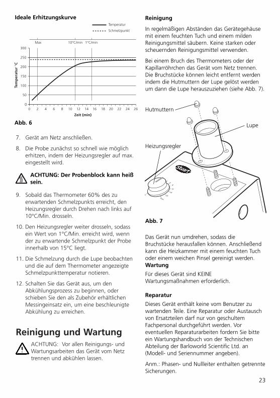
Bei einem Bruch des Thermometers oder derKapillarröhrchen das Gerät vom Netz trennen.Die Bruchstücke können leicht entfernt werdenindem die Hutmuttern der Lupe gelöst werdenum dann die Lupe herauszuziehen (siehe Abb. 7).
Abb. 6
0
100
150
200
250
300
50
0 2 4 6 8 10 12 14 16 18 20 22 24 26
Zeit (min)
Tem
per
atu
r °C
Max 10°C/min 1°C/min
Temperatur
Schmelzpunkt
Ideale Erhitzungskurve
Abb. 7
Lupe
Hutmuttern
Heizungsregler
Das Gerät nun umdrehen, sodass dieBruchstücke herausfallen können. Anschließendkann die Heizkammer mit einem feuchten Tuchoder einem weichen Pinsel gereinigt werden.Wartung
Für dieses Gerät sind KEINEWartungsmaßnahmen erforderlich.
Reparatur
Dieses Gerät enthält keine vom Benutzer zuwartenden Teile. Eine Reparatur oder Austauschvon Ersatzteilen darf nur von geschultemFachpersonal durchgeführt werden. Voreventuellen Reparaturarbeiten fordern Sie bitteein Wartungshandbuch von der TechnischenAbteilung der Barloworld Scientific Ltd. an(Modell- und Seriennummer angeben).
Anm.: Phasen- und Nullleiter enthalten getrennteSicherungen.
ACHTUNG: Der Probenblock kann heißsein.

Es dürfen nur Ersatzteile verwendet werden, dievon Barloworld Scientific bzw. dessenNiederlassungen geliefert wurden. Der Einbauanderer Teile kann die Sicherheitsfunktionendieses Geräts beeinträchtigen.
Im Zweifelsfall wenden Sie sich bitte an dieTechnische Abteilung von Barloworld ScientificLtd. oder an Ihre Verkaufsstelle.
Barloworld Scientific Ltd. Stone, Staffordshire ST15 0SA United KingdomTel: +44 (0) 1785 812121 Fax: +44 (0) 1785 813748 e-mail [email protected]
GarantieBarloworld Scientific Ltd gewährleistet, dassdieses Gerät keine Herstellungs- undMaterialmängel aufweist. Bei Einsatz unternormalen Laborbedingungen gilt diese Garantiefür drei (3) Jahre. Im Falle einer gerechtfertigtenReklamation ersetzt Barloworld Scientific dasdefekte Teil kostenlos.
Diese Garantie gilt NICHT bei Beschädigungdurch Feuer, Unfall, Missbrauch,Vernachlässigung, falscher Einstellung oderReparatur, Schäden durch Adaptierung bei derInstallation, Modifizierung, Einbau von nichtzugelassenen Teilen bzw. Reparatur durchunbefugtes Personal.
24
Technische DatenAnzahl der Proben Drei
Temperaturbereich Umgebungstemp. bis 250°C
Heizrate 1 bis maximal 20 °C/min
Abmessungen (B x T x H) 370 x 140 x 110 mm
Nettogewicht 1,7 Kg
Stromversorgung
SMP11 230V, 50/60Hz, 50W
SMP11/100V/60 100V, 50/60Hz, 50W
SMP11/120V/60 120V, 50/60Hz, 50W
Ersatzteile / Zubehör
SMP11/1 Ersatzthermometer (auf Alkoholbasis), 0 bis 250°C.
SMP1/2 Messing-Kühlfinger
SMP1/4 Schmelzpunktröhrchen (an beiden Enden offen)
SMP2/1 Schmelzpunktröhrchen (an beiden Enden verschlossen)
SMP10/1 Schmelzpunktröhrchen (an einem Ende verschlossen

These products meet the relevant ECharmonised standards for radio frequencyinterference and may be expected not to
interfere with, or be affected by, other equipment withsimilar qualifications. We cannot be sure that otherequipment used in their vicinity will meet these standards
and we cannot guarantee that interference will not occurin practice. Where there is a possibility that injury,damage or loss might occur if equipment malfunctionsdue to radio frequency interference, or for general advicebefore use, please contact the Technical ServiceDepartment of Barloworld Scientific Ltd.
Declaration of Conformity
Scientific

INSPECTION REPORT
MODEL SMP11
ELECTRICAL SAFETY
1. Earth continuity ❏2. Insulation ❏3. Flash test ❏
FUNCTIONAL
1. Indicators ❏2. Temperature control ❏3. Visual acceptance ❏
QUALITY CONTROL INSPECTOR
✓
✓
✓
✓
✓
✓
Barloworld Scientific LtdBeacon Road Stone Staffordshire ST15 0SAUnited KingdomTel: +44 (0)1785 812121 Fax: +44 (0)1785 813748 www.barloworld-scientific.com
Barloworld Scientific France SASZI du Rocher Vert - BP 7977793 Nemours Cedex FranceTel: +33 1 64 45 13 13 Fax: +33 1 64 45 13 00 e-mail: [email protected]
Barloworld Scientific Italia SrlVia Alcide de Gasperi 5620077 Riozzo di Cerro al LambroMilano ItaliaTel: +39 (0)2 98230679Fax: +39 (0)2 98230211 e-mail: [email protected]
Barloworld Scientific US Ltd 350 Commerce Drive Rochester NY 14623 USATel: (800) 828-6595 Fax: (585) 334-0241www.dynalabcorp.com
Afora S.A.Calle Aribau 24008006 Barcelona SpainTel: +343 93-306 98 00Fax: +343 93-306 98 23e-mail: [email protected]
Scientific