maverick ii™ commercial packaged rooftop cooling and heating · r 1 y 1 y y yyyyyyyyyyyyyyyyy mp...
TRANSCRIPT

Replacement Parts List No. 700015800Revision T 12/2017
DaikinMcQuay
Maverick II™ Commercial Packaged Rooftop
Cooling and HeatingMPS
061 - 075Vintage E
To find your Daikin Applied parts distributor, call 1-800-377-2787 or visit www.DaikinApplied.com

Maverick II Rooftop, MPS 061- 075, Vintage E Rev. T 12/17 RPL 7000158 / Page 2
ContentsParts List Revision History .................................................................................................................................. 4Nomenclature Model Number- Dataplate ................................................................................................................................. 5 Serial Number ................................................................................................................................................... 5 Model Number- Complete ............................................................................................................................ 6- 8Electrical Legend ............................................................................................................................................ 9- 11Section A- Outdoor/Return Air Section 100% Outside Air Damper with Hood- No Return Air Plenum ...................................................................12- 14 0- 30% Outside Air Section w/ ACT3 ........................................................................................................ 15, 16 0- 100% Economizer Section with Barometric Exhaust Damper .................................................................... 17 0- 100% Economizer Section with Prop Exhaust Fan & Damper ................................................................... 18 0 - 100% Economizer Damper w/ ACT3 .................................................................................................... 19, 20 California Title 24 Assembly ............................................................................................................................ 21 Prop Exhaust Fan & Damper Detail ............................................................................................................... 22 Prop Exhaust Fan Control Box ...................................................................................................................... 23 Design Flow (Code 20= JE) ............................................................................................................................ 24 Section Mounted Controls: OAE, RAE, RAT, SD2 .......................................................................................... 25Section B- Draw-Thru Filter Section Section Mounted Controls- PC5 ..................................................................................................................... 25 Filters ............................................................................................................................................................. 26Section D- Draw-Thru Cooling Section Evaporator Coils, Drain Pans, Gasketing ....................................................................................................... 27Section E- Draw-Thru Heat Section Hot Water Coil Heat, Mixing Valves and Actuator- VM1 ................................................................................. 28Section F- Supply Air Section Air Foil Fan- Double Width (Code 31= 30A*) .................................................................................................. 29 Air Foil Fan- Single Width (Code 31= 40B*) ................................................................................................... 30 Fan Mounts- 30” Airfoil Double Width Fan ...................................................................................................... 31 Fan Mounts- 40” Airfoil Single Width Fan ....................................................................................................... 32 Supply Air Fan Motors ..................................................................................................................................... 33 Inverters .................................................................................................................................................... 34, 35 Line Reactors ................................................................................................................................................. 36 Section Mounted Controls: PC7, HL22, EFT, OAT, DAT ................................................................................. 37Section G- Blow-Thru Heat Section Electric Heat— Heaters, Diffusers, Hi Limit Cutouts HL1- 20, 31- 50 ....................................................... 38, 39 Electric Heat Control Box (02/13 & Earlier) .............................................................................................. 40- 44 Electric Heat Control Box (03/13 & Later) ................................................................................................. 45- 49 Gas Heat- Vestibules, Heat Exchangers and Primary Components .............................................................. 50 Gas Heat- Modulating Burner ................................................................................................................... 51, 52 Gas Heat- Burner Controls ............................................................................................................................. 53 Gas Train- Inlet ............................................................................................................................................... 54 Gas Train- Controls: GV2, GV3 ...................................................................................................................... 54 Gas Train- Outlet ............................................................................................................................................. 54 Gas Heat- Cabinet Doors, Gasketing, Hardware, and Flue Box Mounting ..................................................... 55Section K- Discharge Plenum Section Section Mounted Controls: OAT, DAT AND Access Door Latching Assemblies, Key, Lock (ALL sections) .... 56Section M- Condenser Section Condenser Fan Deck Assembly- 061E, 062E .......................................................................................... 57, 58 Condenser Fan Deck Assembly- 070E, 075E ........................................................................................... 59, 60 Compressors & Compressor Components- Unit Size 061E, 062E ................................................................. 61 Compressors & Compressor Components- Unit Sizes 070E, 075E ............................................................... 62 Pressure Controls Box- 061E, 062E: AFD11, AFD21, LR11, LR21, LP1, LP2, HP1, HP2 ........................ 63, 64 Pressure Controls Box- 070E, 075E: AFD11, AFD21, LR11, LR21, LP1, LP2, HP1, HP2, PC13, PC23 ...... 65, 66 Factory Supplied Line Voltage Box: Code 23= YY*FY: T6, DS6, FU6A, FU6B, FU6C ................................... 67

Maverick II Rooftop, MPS 061- 075, Vintage E Rev. T 12/17 RPL 7000158 / Page 3
Contents, ContinuedSection N- Main Control Box (02/13 & Earlier) Control Panel- MicroTech III- Diagram ............................................................................................................ 68 Control Box Component Label Diagram ......................................................................................................... 69 Control Panel- MicroTech III- Components ............................................................................................... 70, 71 Power Panel- Diagram .................................................................................................................................... 72 Power Panel- Components Terminal Blocks, T1 Transformer & Fusing, Fuses, Plugs ........................................................................... 73 Fusing, Phase Protection, Power Blocks ..................................................................................................... 74 Receptacle, Disconnect Switch .................................................................................................................... 75 Supply MMP10 & M10 Fan Contactor .................................................................................................... 76- 80 Compressor MMP1- 4 and Contactor M1- 4- 062E ....................................................................................... 81 Compressor MMP1- 6 and Contactor M1- 6- 070E ....................................................................................... 82 Compressor MMP1- 6 and Contactor M1- 6- 075E ....................................................................................... 83 Condenser Fan MMP11, 12, 13, 21, 22, 23 & Contactors M11- 24: Fantrol Units (Code 47= 1) ..................... 84 Condenser Fan MMP12- 24, Contactors M11- 24, Fuses F11, F21: Speedtrol Units (Code 47= 2) ................ 85Section N- Main Control Box (03/13 & Later) Control Panel- MicroTech III- Diagram ............................................................................................................ 86 Control Box Component Label Diagram ......................................................................................................... 87 Control Panel- MicroTech III- Components ............................................................................................... 88, 89 Power Panel- Diagrams .................................................................................................................................. 90 Power Panel- Components Terminal Blocks, T1 Transformer & Fusing, Fuses, Plugs ........................................................................... 91 Fusing, Phase Protection, Power Blocks ..................................................................................................... 92 Receptacle, Disconnect Switch .................................................................................................................... 93 Supply MMP10 & M10 Fan Contactor Detail Diagrams ............................................................................... 94 Supply Fan Components ........................................................................................................................ 95- 101 Compressor MMP1- 4 and Contactor M1- 4- 061E, 062E ......................................................................... 102 Compressor MMP1- 6 and Contactor M1- 6- 070E .................................................................................... 103 Compressor MMP1- 6 and Contactor M1- 6- 075E .................................................................................... 104 Condenser Fan MMP11, 12, 13, 21, 22, 23 and Contactors M11- 24: Fantrol Units (Code 47= 1) ................ 105 Condenser Fan MMP12- 24, Contactors M11- 24, Fuses F11, F21: Speedtrol Units (Code 47= 2) .............. 106 Intelligent Equipment .................................................................................................................................. 107Section O- Refrigeration Tubing Diagram & Components ................................................................................................................................ 108 Hot Gas Reheat (Code 54= BM) ................................................................................................................... 109

Maverick II Rooftop, MPS 061- 075, Vintage E Rev. T 12/17 RPL 7000158 / Page 4
Parts List Revision History Rev. Date Description New 12/09 New A- R 05/17 Archived Revs. A- R. S 05/17 Page 6- 8: Misc. Nomenclature updates/corrections. Page 25: Rewrote footnote # 2. Page 34: Rewrote footnote # 1. Page 56: Updated/corrected Door Latching component table & rewrote footnote # 1. Page 58, 60: Updated Cond. Mtr. Ref # 111. Rewrote footnotes and footnote notation. T 12/17 Various: Rewrote/corrected pg. headers. Page 5: Misc. updates. Page 6- 8: Misc. Nomenclature updates/corrections. Page 51, 52: Rewrote pg. header. Page 88: Added 2/17 & Later PVM. Moved transf. to pg. 89. Added footnote # 3. Page 89: Added transf. p/ns from pg. 88. Page 108: Rewrote the pg. header & updated the TOC. Page 109: Added pg. for HGRH info. Repaginated the form & updated the TOC.
Daikin Applied, 13600 Industrial Park Blvd., P.O. Box 1551, Minneapolis, MN 55440 (763) 553-5330

Maverick II Rooftop, MPS 061- 075, Vintage E Rev. T 12/17 RPL 7000158 / Page 5
NomenclatureModel Number- Dataplate
MPS 061 E
Light Commercial Packaged Rooftop
Nominal Capacity (tons) 061, 062, 070, 075
Design Vintage
NomenclatureSerial Number
FBO U 09 05 12345
Plant IdentificationFBO = Faribault
Year of Manufacture09= 200910= 201011= 201112= 2012
etc.
U= Unit
Serial Number (Build Sequence)Month of Manufacture01= January02= February03= March04= April05= May06= June 07= July08= August09= September10= October11= November12= December
NomenclatureModel Number

Maverick II Rooftop, MPS 061- 075, Vintage E Rev. T 12/17 RPL 7000158 / Page 6
MPS 061E S A Y 2 EU D 27 AL P1 LE 3 6 Y 1 CY YYYY YY HE YYYY YYY YYYFY Code 01 02 03 04 05 06 07 08 09 10 11 12 13 14 15 16 17 18 19 20 21 22 23
NomenclatureUnit Model Number- Complete
Y FD Y CYYP 4Z105D YYYYYY YYYYYY 30A1 QJY YYYYY 040SEC YYYY YYYYYY YYYYYY Y Y BY Y 4 MS 24 25 26 27 28 29 30 31 32 33 34 35 36 37 38 39 40 41 42 43
R 1 Y 1 Y Y YYYYYYYYYYYYYYYYY MP YYYYY 1250A YY 1 AAA 047C Y Y 10 YYYYYYYY 44 45 46 47 48 49 50-56 57 58 59 60 61 62-64 65 66 67 68 69- 72
Code 01= Unit Type MPS= Commercial Packaged Rooftop
Code 02= Unit Size / Vintage Nominal Tonnage= 061E, 062E, 070E, 075E
Code 03= Cooling Coil S= Small L= Large
Code 04= Heat Type Y= None A= Natural Gas E= Electric W= Hot Water S= Steam
Code 05= Unit Split Y= None F= Split at Fan/Heat Sections
Code 06= Insulation and Liners 2= 1½”, 1½# with solid liners on doors & ceilings 4= 1½”, 1½# with solid liners on Doors, Ceilings and Floors
Code 07= Approval Agency Listing YY= None EU, EY= ETL/MEA- USA
Code 08= Main Control Box Location D= Discharge Plenum F= Supply Fan Section
Code 09= Unit Voltage 12= 208/60/3 29= 230/60/3 27= 460/60/3 37= 575/60/3
Code 10= Starting Option AL= Across- The- Line
Code 11= Field Power Connection and Disconnect P1= Single Power Block: Complete Unit A2= One, thru-the-door Disconnect: Complete Unit
Code 12= Temperature ControlsMicroTech III Controls Digit 1: Communication Type L= LonWorks B= BACNet w/MSTP E= BACNet w/Ethernet S= Standalone (no communication) C= BACNet/MSTP (VAV Contactor configurable) A= Daikin D3 Gateway (VRV communication) Digit 2: Control Type E= Discharge Air w/ Static Pressure Control F= Space OR Zone Ctl. W= Discharge Air w/ Space Control
Code 13= Air Flow Controls Y= None 1= 1 Duct Sensor 2= 2 Duct Sensors 3= 1 Duct and 1 Space Sensor 4= 1 Space Sensor 5= Duct Hi Limit (DHL) Sensor
Code 14= Inverters Y= None 6= SA Fan only no bypass 9= RA Fan only no Bypass
Code 15= Inverter Type Y= None S, B= Daikin Applied MD2- MD6
Code 16= Smoke Detectors Y= None 1= Return Air Fan Section
Code 17= Misc. Aux. Controls YY= None CP= Differential Enthalpy w/ Phase Failure CY= Differential Enthalpy YP= Mechanical Enthalpy w/ Phase Failure

Maverick II Rooftop, MPS 061- 075, Vintage E Rev. T 12/17 RPL 7000158 / Page 7
Code 30= Draw-Thru Heating Section YYYYYY= No Heating Section
Hydronic HeatW22 J 3 E
NomenclatureUnit Model Number- Complete, Continued
Code 18= Misc. Controls/ Unit Length Y_ _ _= None + actual air handler length
Code 19= Return Air Plenum YY= None (no return air section) BY= Bottom Return HY= Back Return
Code 20= Outdoor Air Options AE= 0-100% Outside Air Damper w/ Hood & Act. BE= 0- 30% Outdoor air section w/ Actuator DE= 0- 100% Econ. w/ Barometric Exhaust Damper w/ Act. HE= 0- 100% Econ. w/ Prop Exhaust Damper w/ Act. JE= same as HE + Design Flow
Code 21= Return Air Fan YYYY= No Return Air Fan
Code 22= Exhaust Fan Motor YYY= No Exhaust Fan J J Y
Code 23= Misc. Electrical Options Digit 1, 2: None YY= None Digit 3: Inverter Brand Y= None B= Daikin Applied Digit 4: 115V Service Outlet Y= None F= Factory Supplied Line Voltage & Receptacle Digit 5: IE Y= None A= Intelligent Equipment (IE)
Code 24= Exhaust Fans Y= None 1= 1 Prop Exhaust Fan w/ Hood 2= 2 Prop Exhaust Fans w/ Hood
Code 25= Draw-Thru Filter Section AB= Angular/30% Throwaway FY= Flat w/ no filter media FE= Flat/95% Cartridge SD= Staggered/65% Cartridge SE= Staggered/95% Cartridge
Code 26= Blank Draw-thru Section Y= None
Code 27= Draw-Thru Drain Pan/Cooling Coil Section CYYP, CYYY= Cooling coil section w/painted galvanized steel sloped Drain Pan CYYS= Cooling coil section w/stainless steel sloped Drain Pan
Always YJ= Premium Eff. ODP
J= 5.0 HP
5= 5 Row6= 6 Row
10= 10 Fins-per-inch12= 12 Fins-per-inch
4Z= Type 4EZ
D= Lanced Aluminum
Code 28= Draw-Thru Cooling Coil YYYYYY= No Cooling Coil4Z 10 5 D
Code 29= Draw-Thru Heating Coil YYYYYY= No Heating Coil
3= 3 Way HW Valve
E= 1¼” Valve Pkg. G= 2” Valve Pkg. J= 3.0” Valve Pkg.F= 1½” Valve Pkg. H= 2½” Valve Pkg.
W11= 5WH0901H (9FPI, 1 Row 5WH HW Coil)W22= 5WS0902C (9FPI, 2 Row 5WS HW Coil)
E= Electric ActuatorY= Less Actuator
Code 31= Supply Air Fan 30A()= 30” Airfoil Double Width, w/o vanes 40B()= 40” Airfoil Single Width, w/o vanes ()= Fan Isolators: 1= RIS; 3= Spring w/ Seismic Snubbers
Always YJ= Premium Eff. ODP Motor
H= 3.0 HP M= 15.0 HP R= 40.0 HPJ= 5.0 HP N= 20.0 HP S= 50.0 HPK= 7.5 HP P= 25.0 HP L= 10.0 HP Q= 30.0 HP
Code 32= Supply Air Fan MotorK J Y
E= Modulating Burner/Maximum gas pressure= 0.5 psiS= Stainless Steel Heat Exchanger
MBH (in 10’s)ex. 040= 200 MBH [040,064,079]
Gas Heat Breakdown:020 S E C
A= Low CFM Baffle PositionB= Medium CFM Baffle PositionC= High CFM Baffle Position
Always ‘Y’
1= 1 Stage 2= 2 Stages 4= 4 Stages 6= 6 Stages
E020= 20 KW Heater E100= 100 KW Heater E040= 40 KW Heater E120= 120 KW HeaterE060= 60 KW Heater E160= 160 KW HeaterE080= 80 KW Heater E200= 200 KW Heater
Electric Heat Breakdown:E020 1 Y
Code 35= Blow- Thru Drain Pan YYYY= None
Code 36= Blow-Thru Cooling Coil YYYYYY= No Cooling Coil
Code 36= Blow-Thru Heating Coil YYYYYY= No Heating Coil
Code 33= Miscellaneous Electrical YYYYY= None YFYYY= California Title 24 Economizer w/ Fault Detection/Diagnosis (FDD) YYGYY= Ebtron Gold YYYYE= Electrofin Coated Cooling Coil
Code 34= Blow Thru Heat SectionYYYYYY= No section, cooling only

Maverick II Rooftop, MPS 061- 075, Vintage E Rev. T 12/17 RPL 7000158 / Page 8
NomenclatureUnit Model Number- Complete, Continued
Code 37= N/A to MPS YYYYYY= None Code 38= Attenuator Section Y= None- No Section
Code 39= Final Filter Section Y= None
Code 40= Discharge Plenum BY= Bottom Discharge LY= LH Side Discharge
Code 41= Blank Compartment Section- Out of Airstream Y= None- No Section
Code 42= Compressor Capacity Control 4= 4 steps 6= 6 steps
Code 43= Condenser OptionsDigit 1: Air Coil Y= None M= 25mm Micro Channel Coil P= 25mm Coated Micro Channel Coil T= 32mm Micro Channel Coil U= 32mm Coated Micro Channel CoilDigit 2: Condenser Options Y= None G= Coil Guards, Steel S= Seal Tite Conduits B= G + S
Code 44= Compressor Type R= Scroll R410a
Code 45= Compressor Isolation 1= Resilient Rubber-in-Shear
Code 46= Piping Options Y= None 1= Hot Gas Bypass, Circuit #1 only
Code 47= Low Ambient Operation 1= Fantrol Standard Fans 2= Speedtrol Standard Fans
Code 48= IBC Seismic Constr/Power Factor Capacitors Y= None
Code 49= Fan Section Options Y= None
Code 50= Blender Section Y= None
Codes 50- 53 Always Y’s (11)
Code 54= Hot Gas/Liquid Subcool Reheat YY= None BM= Blow-Thru Modulating (includes SpeedTrol)
Codes 55- 56 Always Y’s (9)
Code 57= MPS IM MP= MPS IM Bulletin included
Code 58= Return Air Fan Drive Selection YYYYY= None
A= Standard Service Factor/Fixed DriveFan RPM
Code 59= Supply Air Fan Drive Selection1250 A
Code 60= Miscellaneous YY= None
Code 61= Packaging 1= Steel Skid
Codes 62- 64= Warranty
Code 65= Always 047C
Code 66= Drain Connection Location R= RH/ Drive Side L= LH/Opp. Drive Side Y= None
Code 67= ASHRAE Certification Y= None B= AHRI Certified-90.1 2010 C= AHRI Certified-90.1 2013 D= AHRI Certified-90.1 2016
Code 68= Short Circuit Current Rating YY= None 10= 10 SCCR 22= 22 SCCR 65= 65 SCCR
Code 69- 72 N/A to MPS Always YYYYYYYY

Maverick II Rooftop, MPS 061- 075, Vintage E Rev. T 12/17 RPL 7000158 / Page 9
Electrical Legend Schematic Sym. Description Location ACT3, 4 Actuator Motors, Economizer Dampers Economizer Section ACT7 Actuator Motor, Heat Face/Bypass Coil Section, Heat ACT8 Actuator Motor, Cool Face/Bypass Coil Section, Cool ACT 10, 11 Actuator Motors, Exhaust Dampers Return Air Section AFD10 Inverter, Supply Fan AFD or Supply Fan Sect. AFD/VFD11 Inverter, Speedtrol Motor Condenser Section AFD20 Inverter, Exhaust Fan AFD or Supply Fan Sect. AFD/VFD21 Inverter, Speedtrol Motor Condenser Section AS Blower Air Switch Furnace Section BM Burner Blower Motor Furnace Section CB10 Circuit Breaker, Supply Fan (575V only) Main Control Box COMPR1- 6 Compressors Condenser Section DAT Discharge Air Temperature Sensor Discharge section DHL Duct High Limit Main Control Box DS1 Disconnect, Total Unit or Condenser/Heat Main Control Box DS3 Disconnect, Electric Heat Electric Heat Section DS6 Disconnect- Unit Supplied Line Voltage Condenser Section EFT Entering Air Temperature Sensor Supply Fan Section EXPA, B Expansion Boards Main Expansion Board F1, 1A Fuses, Control Circuit, T1 Primary Main Control Box F1C Fuse, Control Circuit, T1 Secondary Main Control Box F2 Fuse, Control Circuit Condenser Control Box F3 Fuse, Burner Motor Main Control Box F4 Fuse, T4 Transformer Main Control Box F6A, B, C Fuses, Unit Supplied Line Voltage Condenser Section F10 Fuse, Supply Fan (575V only) Main Control Box F11 Fuse, Speedtrol Motor Main Control Box F20 Fuse, Return/Exhaust Fan Main Control Box F21 Fuse, 208V Speedtrol Motor Main Control Box FB8 Fuseblock, Main Transformer Main Control Box FB31- 40 Fuseblocks, Electric Heat (Top Bank) Electric Heat Section FB41- 50 Fuseblocks, Electric Heat (Bottom Bank) Electric Heat Section FD Flame Detector Furnace Section FLC Fan Limit Control Furnace Section FS1 Freezestat Coil Section, Heat/Cool FSG Flame Safeguard Furnace Section GRD Ground All Control Boxes GV1 Gas Valve, Pilot Furnace Section GV2, 3 Gas Valves, Main Furnace Section HL1- 10 High Limits, Elec. Heaters (Top Bank) Electric Heat Section HL11- 20 High Limits, Elec. Heaters (Bottom Bank) Electric Heat Section HL22 High Limit, Gas Heat (Prefilters) Supply Air Section HL31- 40 High Limits, Elec. Heaters (Top Bank) Electric Heat Section HL41- 50 High Limits, Elec. Heaters (Bottom Bank) Electric Heat Section HP1, 2 High Pressure Controls Condenser Manifold HP5 High Pressure Control, Gas Furnace Section HS1 Heat Switch, Electric, Shutdown Main Control Box HTR1- 6 Crankcase Heaters On Compressors IT Ignition Transformer Furnace Section LP1, 2 Low Pressure Controls, Refrigerant Condenser Manifold LP5 Low Pressure Control, Gas Furnace Section LR20 Line Reactor- Exhaust Fan Main Control Box M1- 6 Contactors, Compressors Main Control Box

Maverick II Rooftop, MPS 061- 075, Vintage E Rev. T 12/17 RPL 7000158 / Page 10
Electrical LegendContinued
M10 Contactor, Supply Fan Main Control Box M11- 15 Contactors, Condenser Fans, Circuit #1 Main Control Box M21- 25 Contactors, Condenser Fans, Circuit #2 Main Control Box M29 Contactor, Burner Motor Furnace Section M30 Contactor, Supply Fan Inverter Inverter Bypass Box M31- 39 Contactors, Elec. Heaters (Top Bank) Electric Heat Section M41- 50 Contactors, Elec. Heaters (Bottom Bank) Electric Heat Section M51, 52, 53 Contactors, Prop Exhaust Fan Motor Return Air Section MCB1 Microprocessor Control Board Main Control Box MJ Mechanical Jumpers Terminal Blocks MMP1- 6 Manual Motor Protectors, Compressors Main Control Box MMP10 Manual Motor Protector, Supply Fan Main Control Box MMP11- 14 Manual Motor Protectors, Cond. Fans Ckt. 1 Main Control Box MMP51, 52 Manual Motor Protectors, Prop Exhaust Return Air Section MP1- 6 Motor Protectors, Compressors On Compressors NB1, 2 Neutral Blocks Main Control Box OAE Outside Air Enthalpy Control Economizer Section OAT Outside Air Temperature Sensor Discharge Bulkhead OL10 Overload Relays, Supply Fan Main Control Box OL51, 52 Overload Relays, Prop Exhaust Fan Return Air Section PB1 Powerblock, Main Main Control Box PB3 Powerblock, Electric Heat Electric Heat Section PC5 Pressure Control, Clogged Filter Filter Section PC7 Pressure Control, Proof of Airflow Supply Air Filter PC8 Pressure Control, Minimum Airflow Evaporator Coil Section PVM1 Phase Voltage Monitor Main/Cond. Control Box R1, 2 Relays, High Pressure Reset Main/Cond. Control Box R5.1- 8.1 Relays, Compressor, Safety/Cool Fail Main/Cond. Control Box R9, 10 Relays, Compressor Lockout Main/Cond. Control Box R11 Relay, Speedtrol Inverter Main/Cond. Control Box R13.1, 14.1 Relays, Compressor, Safety/Cool Fail Main/Cond. Control Box R12, 13, 14 Relays, Condenser Fans Main/Cond. Control Box R18, 19 Relays, Cool Failure Indicator Main Control Box R20 Relay, HW or Electric Heat Main Control Box R20, 21, 22 Relays, Gas Heat Furnace Section R23 Relay, Gas Heat Valve or Electric Heat Furnace or Elec. Ht. CB R24 Relay, Gas Heat Alarm Main Control Box R25 Relay, Gas Heat Start, Supply Fan Inverter Main Control Box R26 Relay, Occupied/Unoccupied Main Control Box R27 Relay, Exhaust Dampers Main Control Box R30 Relay, Cool Valve w/ F&B Main Control Box R46, 47 Relays, Supply Fan Inverter increase/decrease Main Control Box R62 Relay, Special Main Control Box R67 Relay, Supply Fan Enable Main Control Box R69 Relay, Inverter Bypass VAV Box Interlock Main Control Box R81, 82 Relays, Inverter Reset Main Control Box R83- 88 Relays, Smoke Main Control Box RAE Return Air Enthalpy Sensor Return Air Section RAT Return Air Temperature Sensor Return Air Section REC1 Receptacle, Main Box Main Control Box R24 Relay, Gas Heat Alarm Main Control Box R25 Relay, Gas Heat Start, Supply Fan Inverter Main Control Box
Schematic Sym. Description Location

Maverick II Rooftop, MPS 061- 075, Vintage E Rev. T 12/17 RPL 7000158 / Page 11
Electrical LegendContinued
R26 Relay, Occupied/Unoccupied Main Control Box R27 Relay, Exhaust Dampers Main Control Box R30 Relay, Cool Valve w/ F&B Main Control Box R46, 47 Relays, Supply Fan Inverter increase/decrease Main Control Box R62 Relay, Special Main Control Box R67 Relay, Supply Fan Enable Main Control Box R69 Relay, Inverter Bypass VAV Box Interlock Main Control Box R81, 82 Relays, Inverter Reset Main Control Box R83- 88 Relays, Smoke Main Control Box RAE Return Air Enthalpy Sensor Return Air Section RAT Return Air Temperature Sensor Return Air Section REC1 Receptacle, Main Box Main Control Box REC3 Receptacle, Field Power, 115V Discharge Bulkhead S1 Switch, System On/Off Main Control Box S3 Switch, Furnace On/Off Furnace Section S4 Switch, Inverter Bypass On/Off Main Control Box S7 Switch, Local On/Off/Auto to Controller Main Control Box SD2 Smoke Detector, Return Air Return Air Section SPS1, 2, 3 Static Pressure Sensors, Duct or Building Main Control Box SPTRL Switch- Speedtrol Pressure Condenser Section SR1- 3 Sequence Relays, Electric Heat Electric Heat Section SV1- 4 Solenoid Valves, Liquid Discharge Bulkhead SV5- 8 Solenoid Valves, Hot Gas Discharge Bulkhead T1 Transformer, Main Control Main Control Box T2 Transformer, Unit 24V Main Control Box T3 Transformer, Controller, 18V Main Control Box T4 Transformer, Exhaust Dampers Main Control Box T5 Transformer, Electric Heat Electric Heat Section T6 Transformer, Unit Supplied 120V Power Condenser Section T7 Transformer, Gas Pilot Valve Furnace Section T8 Transformer, Gas Main Valve Furnace Section TB1 Terminal Block, 115V, Field Main Control Box TB2 Terminal Block, 24V, Field Main Control Box TB5 Terminal Block, 115V, Factory Main Control Box TB6 Terminal Block, 115V/24V, Factory Main Control Box TB7, 8 Terminal Blocks, 24V, Factory Main Control Box TB10 Terminal Block, Heating Main Control Box TB11 Terminal Block, Heating Electric Heat Section TB12, 13 Terminal Blocks, Electric Heat, Power Electric Heat Section TD20 Time Delay, Duct Hi Limit Main Control Box TR1, 2 Transducers, Pressure Main Control Box VM1 Valve Motor, Heating Heating Section VM5 Valve Motor, Cooling Coil Section, Cool VV1 Vent Valve Furnace Section ZNT1 Zone Temperature Sensor, Control Field Installed
Schematic Sym. Description Location

Maverick II Rooftop, MPS 061- 075, Vintage E Rev. T 12/17 RPL 7000158 / Page 12
11
Ref. Part Part Qty. No. Description Number N/S Damper Assy- Complete 1 1 100 Damper Only 098313701 1 9 Liner 056132601 2 10 Panel- Hood Side 056131903 1 11 Panel- Hood Side 056131904 1 12 Panel- Hood Top 056131802 1 13 Louver 056132002 3 14 Channel- Support 056132303 2 15 Channel- Support 056132102 2
915
15
14
121009
Section A- Outdoor/Return Air Section100% Outside Air Damper with Hood
Code 20= AE AND Code 19= YYNo Return Air Plenum
N/S= Not shown on diagram.1 This Damper Assy. includes the Damper, Damper Linkage, and Actuator. For Damper Assy. components see the following
two pages. For complete Damper Assembly p/ns contact Daikin Applied with model and serial number information so that the correct assembly can be identified.
10
Air Flow
Section B
13

Maverick II Rooftop, MPS 061- 075, Vintage E Rev. T 12/17 RPL 7000158 / Page 13
Section A- Outdoor/Return Air Section100% Outside Air Damper Detail w/ACT3
Code 20= AE AND Code 19= YYDiagrams
25
27
23
29
26
16
28
24
23
21421
46
19
22Motorized Linkage
Detail
14
13
17
20
39
1922

Maverick II Rooftop, MPS 061- 075, Vintage E Rev. T 12/17 RPL 7000158 / Page 14
Section A- Outdoor/Return Air Section100% Outside Air Damper Detail w/ACT3
Code 20= AE AND Code 19= YYComponents
Ref. Part Part Qty. No. Description Number 4 Shaft- Linkage 055979701 2 6 Adapter Plate- Crank Arm 403642801 1 13 Blade- Damper 044195102 12 14 Grille 055616801 2 16 Stop-Anti Rotate, Damper 065779801 2 17 Support- Damper Motor 403642001 1 19 Linkage Bar Drive Tab 044194900 2 20 Crank Arm- Damper 403641901 1 21 Ball Joint- Damper 000887000 4 22 Actuator- Motorized, 24V ACT3 113139501 1 23 Bushing- Linkage Bar, Nylon 046098300 12 24 Bushing- Damper Blade, Nylon 043730400 24 25 Gasket- Vinyl 044193115 12 26 Gasket- Vinyl 045655715 1 27 Plug- Damper End 041003501 12 28 Plug- Damper End 041003502 6 29 Plug- Damper End 041003503 6 39 Bearing- Flange Sleeve 047138504 2

Maverick II Rooftop, MPS 061- 075, Vintage E Rev. T 12/17 RPL 7000158 / Page 15
Section A- Outdoor/Return Air Section0- 30% Outside Air Section w/ ACT3
Code 20= BEDiagrams
30
9
3331
32
26
12
8
10
1411
34
35
15
4813
Linkage Detail:5/12 & Earlier
47
15
3634
36
Linkage Detail:6/12 & Later
34
35
15
36
48
13
47
15
3634

Maverick II Rooftop, MPS 061- 075, Vintage E Rev. T 12/17 RPL 7000158 / Page 16
Section A- Outdoor/Return Air Section0- 30% Outside Air Section w/ ACT3
Code 20= BEComponents
Ref. Part Part Qty. No. Description Number N/S Damper Assembly- Complete 1 1 Damper Only 098313901 2 1 8 Blade- Damper 044193212 3 9 Gasket- Vinyl 055940203 1 10 Gasket- Vinyl 044193124 3 11 Seal- End 055941901 2 12 Grille 055593601 1 13 Support- Motor 5/12 & Earlier 403672201 1 Support- Motor 6/12 & Later 403672202 1 14 Bar- Linkage 055593701 2 15 Shaft- Linkage 055536608 1 26 Louver 055593202 4 30 Plug- End 041003505 3 31 Plug- End 041003506 3 32 Bushing- Damper Blade 043730400 6 33 Bushing- Linkage Bar, Nylon 046098300 6 34 Ball Joint- Damper 000887000 2 35 Actuator- Motorized, 24V ACT3 113139501 1 36 Crank Arm- Damper 403666401 1 47 Bushing- Actuator 047138504 1 48 Channel Retainer 5/12 & Earlier 403633801 1 Channel Retainer 6/12 & Later 910106063 1N/S= Not Shown on Diagram.1 Damper assy includes the Damper, Damper Linkage, and Actuator. For the complete Damper Assembly p/n contact Daikin
Applied with model and serial number information so that the correct assembly can be identified.2 Damper only, NO Actuator Linkage OR Actuator.

Maverick II Rooftop, MPS 061- 075, Vintage E Rev. T 12/17 RPL 7000158 / Page 17
Section A- Outdoor/Return Air Section0- 100% Economizer Section with Barometric Exhaust Damper
Code 20= DE
Ref. Part Part Qty. No. Description Number N/S Damper Assembly- Complete 1 1 11 Damper Only 098313201 2 1 12 Exhaust Damper Assy.- Barometric 112039647 1N/S= Not Shown on diagram.1 Economizer Damper detail one page after next. For the complete Damper Assembly p/n contact Daikin Applied
with model and serial number information so that the correct assembly can be identified.2 Damper only, NO Actuator Linkage OR Actuator.
12
11
Back Return (Code 19= HY) shown.
Air Flow

Maverick II Rooftop, MPS 061- 075, Vintage E Rev. T 12/17 RPL 7000158 / Page 18
Section A- Outdoor/Return Air Section0- 100% Economizer Section with Prop Exhaust Fan & Damper
Code 20= HE AND Code 24= 1, 2
20
420
41
15
Section Assembly Detail2 fan arrangement shown
(Code 24= 2)
Fan Guard
Ref. Part Part Qty. No. Description Number 420 Fan Assembly 1 208/230/460V 111056601 2
Fan Assembly 1 575V 111056602 2
15 Fan Guard 111181901 1 3
20 Panel- Weather Hood 111173101 1 3
41 Hood- Prop Exhaust 111182301 1 3
N/S Grille Only- Prop Exhaust Hood 111182101 1 3
N/S= Not Shown on diagram.1 See detail following Isolation Damper Detail. 2 Quantity may be one (Code 24= 1) OR two (Code 24= 2).3 Quantity is PER fan.
420

Maverick II Rooftop, MPS 061- 075, Vintage E Rev. T 12/17 RPL 7000158 / Page 19
Section A- Outdoor/Return Air Section0 - 100% Economizer Damper Detail
Code 20= DE, HE, JEDiagrams
16 24
13
27
25
28
29
19
23
26
18
24
LinkageDetail:With
Actuator(Code 20= *E)
22
4 21
721
6
11
31
123
19
1922

Maverick II Rooftop, MPS 061- 075, Vintage E Rev. T 12/17 RPL 7000158 / Page 20
Section A- Outdoor/Return Air Section0 - 100% Economizer Damper w/ ACT3
Code 20= DE, HE, JEComponents
Ref. Part Part Qty. No. Description Number Damper Assy- Complete 1 1 Damper Only 098313201 2 1 4 Shaft Assembly 058390001 1 6 Plate- Crank Arm 066302059 1 7 Shaft- Linkage 058389901 1 11 Channel- Support 403630501 1 13 Blade- Damper 044195102 12 16 Stop/Anti-Rotate- Damper 065779801 4 18 Bar- Linkage 044194800 2 19 Drive Tab- Linkage Bar 044194900 2 21 Ball Joint- Damper 000887000 4 22 Actuator- 24V ACT3 113139501 1 23 Bushing- Linkage Bar 046098300 12 24 Bushing- Damper Blade 043730400 24 25 Gasket- Vinyl 044193115 12 26 Gasket- Vinyl 045655715 2 27 End Plug- Damper 041003501 12 28 End Plug- Damper 041003502 6 29 End Plug- Damper 041003503 6 31 Bushing- Actuator 047138504 1 123 Channel- Actuator 403659701 1 N/S Gasket- Neoprene 3 056003501 4N/S= Not Shown on Diagram.1 Includes the Damper Assy, Actuator Linkage, and Actuator. For the complete Damper Assembly p/n contact Daikin Applied
with model and serial number information so that the correct assembly can be identified.2 Damper only, NO Actuator Linkage OR Actuator.3 Applied from outer edge of assembly to inside edge of center support and flush with edge of the bottom channel.

Maverick II Rooftop, MPS 061- 075, Vintage E Rev. T 12/17 RPL 7000158 / Page 21
Section A- Outdoor/Return Air SectionCalifornia Title 24 Assembly
Code 33= *F***
Ref. Part Part Qty. No. Description Number 3533 Cover, Mounting Switch 404159561 1 3534 Bracket, Mounting Switch 404159562 1 3535 Switch, Push Button SPDT 033696300 2 3536 Bushing, Conduit 113116301 1
3533
3536
3534
3535
Maverick II Rooftop, MPS 061- 075, Vintage E Rev. T 12/17 RPL 7000158 / Page 22
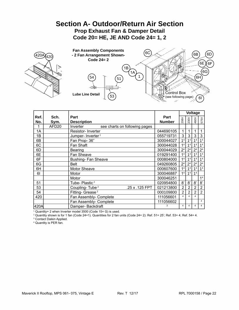
Section A- Outdoor/Return Air SectionProp Exhaust Fan & Damper DetailCode 20= HE, JE AND Code 24= 1, 2
6B
6E
6G6H
6I
Fan Assembly Components- 2 Fan Arrangement Shown-
Code 24= 2
54
53
51
Lube Line Detail
11A
1B
Control Box(see following page)
6C 6D
6F
420420A
Voltage Ref. Sch. Part Part No. Sym. Description Number 1 AFD20 Inverter see charts on following pages 1A Resistor- Inverter 044690105 1 1 1 1 1B Jumper- Inverter 1 055719731 3 3 3 3 6B Fan Prop- 36” 300044027 14 14 14 14
6C Fan Shaft 300044028 14 14 14 14
6D Bearing 300044029 24 24 24 24
6E Fan Sheave 019291400 14 14 14 14
6F Bushing- Fan Sheave 000804000 14 14 14 14
6G Belt 049260805 24 24 24 24
6H Motor Sheave 000607600 14 14 14 14
6I Motor 300046887 14 14 14
Motor 300046251 14
51 Tube- Plastic 2 020954800 8’ 8’ 8’ 8’ 53 Coupling- Tube 2 .25 x .125 FPT 021213800 2 2 2 2 54 Fitting- Grease 2 000109800 2 2 2 2 420 Fan Assembly- Complete 111056601 4 4 4
Fan Assembly- Complete 111056602 4
420A Damper- Backdraft 3 4 4 4 4
208V
230V
460V
575V
1 Quantity= 2 when Inverter model 3500 (Code 15= G) is used.2 Quantity shown is for 1 fan (Code 24=1). Quantities for 2 fan units (Code 24= 2): Ref. 51= 25’; Ref. 53= 4; Ref. 54= 4.3 Contact Daikin Applied.4 Quantity is PER fan.

Maverick II Rooftop, MPS 061- 075, Vintage E Rev. T 12/17 RPL 7000158 / Page 23
Section A- Outdoor/Return Air SectionProp Exhaust Fan Control Box
Code 20= HE, JE AND Code 24= 1, 2
220
230
2 Fan Unit shown
Voltage Ref. Sch. Part Part No. Sym. Description Number 220 OL51, 52 Overload 349934663 2 Overload 349934662 2 Overload 349934660 2 Overload 349934659 2 230 M51, 52 Contactor 349932123 2 2 Contactor 349932121 2 2
208V
230V
460V
575V
OL51 OL52
M51 M52
Voltage Code Inverter Part 15= Number S AFD20- MD2 193475809 1 1 AFD20- MD2 193475825 1
208V
230V
460V
575V
Inverter- 1 Fan Units (Code 24= 1) 1
Voltage Code Inverter Part 15= Number S AFD20- MD2 193475811 1 1 AFD20- MD2 193475827 1
208V
230V
460V
575V
Inverter- 2 Fan Units (Code 24= 2) 1
Prop Exhaust Fan Control Box & Inverter- (02/2013 & Earlier)
Prop Exhaust Fan Control Box & Inverter- (03/2013 & Later)
220
230
220
230
2 Fan Unit shown
Voltage Ref. Sch. Part Part No. Sym. Description Number 220 OL51, 52 Overload 193548010 2 Overload 193548009 2 Overload 193547910 2 Overload 193547909 2 230 M51, 52 Contactor 25A 193537304 2 Contactor 16A 193592006 2 Contactor 9A 193534106 2 Contactor 7A 193534105 2
208V
230V
460V
575V
OL51 OL52
M51 M52
Voltage Code Inverter Part 15= Number B AFD20- MD4 193552215 1 1 AFD20- MD4 193552202 1
208V
230V
460V
575V
Inverter- 1 Fan Units (Code 24= 1) 2
Voltage Code Inverter Part 15= Number B AFD20- MD4 193552217 1 1 AFD20- MD4 193552204 1
208V
230V
460V
575V
Inverter- 2 Fan Units (Code 24= 2) 2
220
230
1 Note that the original (mid 2010 and earlier) VFDs are no longer available. For more information and replacement components, see the Supply Fan Inverter Section 02/13 & Earlier.
2 The replacement VFD Keypad for MD4 Inverters is p/n is 300040924.

Maverick II Rooftop, MPS 061- 075, Vintage E Rev. T 12/17 RPL 7000158 / Page 24
Section A- Outdoor/Return Air SectionDesign FlowCode 20= JE
Ref. Part Part Qty.1
No. Description Number 1 Louver Panel Left Hand Door 059595204 10 Louver Panel Right Hand Door 059595203 10 2 Grille 055541401 1 3 Gasket 055921402 2 4 Gasket 055921401 1 9 Potentiometer 098663701 1 12 O’Ring- Potentiometer 098663801 1 104 Panel- Vane 098661802 1 105 Shaft- Upper 098662601 1 106 Bearing- Lower 091634501 1 109 Crank Arm Assy Left Hand Door 091658802 1 Crank Arm Assy Right Hand Door 091658801 1 110 Link Arm 2 1 120 Bearing 060014201 1 127 Bearing 047138535 1 130 Spring- Main .75” x 2” 098664801 1 131 Spring- Secondary .30” x 1.5” 098664901 1 N/S Leveling Kit- Design Flow 091659301 1
2
9 127
12
110120 109 104
105
106
131
130104
1
Section Final Assembly
Design Flow Vane and Vane Bearings Detail
Adjuster Control AssyDetail
SpringDetail
LH Louvered Door Assy
RH Louvered Door Assy
Louvered DoorAssembly Detail
3➤
➤
4
1 Quantity is PER door.2 P/N is unit specific. Contact Daikin Applied with overall length and bolt hole spacing so that the correct part can be
identified.

Maverick II Rooftop, MPS 061- 075, Vintage E Rev. T 12/17 RPL 7000158 / Page 25
Section A- Outdoor/Return Air SectionSection Mounted Controls- OAE, RAE, RAT, SD2
Return Air Opening
30
Return Air
Opening
30
Ref. Part Part Qty. No. Description Number 30 Smoke Detector SD2 098873101 1
SD2- Return Air Smoke DetectorCode 16= 1
Back ReturnCode 19= HY
Bottom ReturnCode 19= BY
7
Ref. Part Part Qty. No. Description Number 7 Return Air Temp. Sensor- RAT 193414602 1
RAT- Outdoor/Return Air Temperature Sensor
Section B- Draw-Thru Filter SectionSection Mounted Controls- PC5
Ref. Part Part Qty. No. Description Number 65 PC5 Pressure Control 065493801 1
Controls PC565
Ref. Part Part Qty. No. Description Number 40 Mount- OAE Enthalpy 1 1 41 Control- OAE 1 1
40OAE- Mechanical Enthalpy (Code 17= YY)
41
Ref. Part Part Qty. No. Description Number 40 Mount- OAE Enthalpy 2 1 41 Control- OAE 2 1 42 Mount- RAE Enthalpy 2 1 48 Control- RAE 2 1
OAE & RAE Differential Enthalpy (Code 17= C*)
48
42
Economizer Damper
Bottom ReturnShown
Code 19= BY, BE
Bottom ReturnShown
Code 19= BY, BE
1 The original control is obsolete & no longer available. For the OAE Control use p/n 113103601 & Mount 910146257. Minor field modifications are required for proper installation & operation when changing to the newer design.
Economizer Damper
40
412 BOTH original controls are obsolete & no longer available. For
the OAE Control use 113103601 & Mount 910146257. For the RAE Control use 113103701 & Mount 055732301. Note that when changing out EITHER ONE of the older style controls BOTH CONTROLS MUST BE CHANGED TO THE NEWER VERSION. When upgrading to the new style controls, field modifications, including the installation of Relay 349934722 (OAER), are required for proper installation & operation.

Maverick II Rooftop, MPS 061- 075, Vintage E Rev. T 12/17 RPL 7000158 / Page 26
Section B- DrawThru Filter/Blank SectionFilters 1
Ref. Part Code Part Qty. No. Description 25= Number Angular Filter Section Code 25= A*, D*, E* N/S Filter 30% Pleated, 16 x 25 x 2" MERV 8 *B 111046306 21 30% Pleated, 16 x 25 x 2" w/ Intersept MERV 8 *C 031298002 21 85% Disposable, 16 x 25 x 2” MERV 13 *H 910102150 21 N/S Filter 30% Pleated, 16 x 20 x 2 MERV 8 *B 111046305 7 30% Disposable, 16 x 20 x 2” w/ Intersept MERV 8 *C 111046505 7 85% Disposable, 16 x 20 x 2” MERV 13 *H 910102152 7 N/S Media Filler Piece ALL 011484101 7 N/S Angle Assembly 2 ALL 056077301 28 Flat Filter Section Code 25= F*, G*, H* N/S Filter, Cartridge 65% Cartridge, 24 x 24 x 12" MERV 11 *D 065810704 8 95% Cartridge, 24 x 24 x 12" MERV 14 *E 065810702 8 95% Cartridge, 24 x 24 x 12" w/ Intersept MERV 14 *G 066302252 8 85% Disposable, 24 x 24 x 2” MERV 13 *H 910110394 8 Gasket, Cartridge 5/8 x 1/16 x 24” ALL 021768924 8 N/S Filter, Cartridge 65% Cartridge, 12 x 24 x 12" MERV 11 *D 065810703 4 95% Cartridge, 12 x 24 x 12" MERV 14 *E 065810701 4 95% Cartridge, 12 x 24 x 12" w/ Intersept MERV 14 *G 066302253 4 85% Disposable, 12 x 24 x 2” MERV 13 *H 910110399 4 Gasket, Cartridge 5/8 x 1/16 x 12” ALL 021768912 8 N/S Pre Filter, 24 x 24 x 2” ALL 111046101 8 N/S Pre Filter, 12 x 24 x 2” ALL 111046103 8 Staggered Filter Section Code 25= L*, S*, T*, V* 65% Cartridge, 24 x 24 x 12” MERV 11 *D 065810704 8 95% Cartridge, 24 x 24 x 12” MERV 14 *E 065810702 8 95% Cartridge, 24 x 24 x 12” w/ Intersept MERV 14 *G 066302252 8 85% Disposable, 24 x 24 x 2” MERV 13 *H 910110394 8 Gasket, Cartridge 5/8 x 1/16 x 12” ALL 021768912 8 N/S Filter, Cartridge 65% Cartridge, 12 x 24 x 12” MERV 11 *D 065810703 4 95% Cartridge, 12 x 24 x 12” MERV 14 *E 065810701 4 95% Cartridge, 12 x 24 x 12” w/ Intersept MERV 14 *G 066302253 4 85% Disposable, 12 x 24 x 2” MERV 13 *H 910110399 4 Gasket, Cartridge 5/8 x 1/16 x 12” ALL 021768912 8 N/S Pre Filter, 24 x 24 x 2” ALL 111046101 8 N/S Pre Filter, 12 x 24 x 2” ALL 111046103 8
Typical Angular Filter Section Shown
Code 25= A*
1 Note that MERV ratings have changed during the production run, so some lower rated filters may no longer be available. Higher MERV filters can be used as a substitute for lower rated filters.
2 Optional- Angle is mounted on leaving air side.
Maverick II Rooftop, MPS 061- 075, Vintage E Rev. T 12/17 RPL 7000158 / Page 27
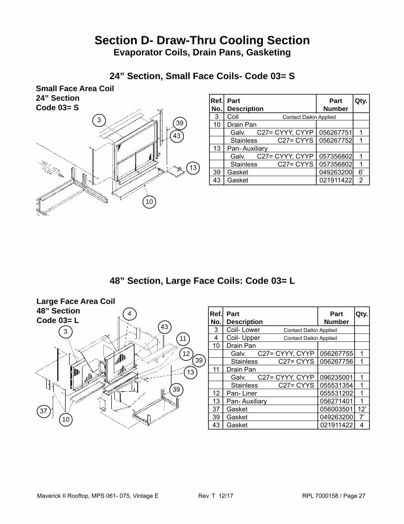
Small Face Area Coil24” SectionCode 03= S
10
13
43
393
Section D- Draw-Thru Cooling SectionEvaporator Coils, Drain Pans, Gasketing
3
4
43
11
1239
13
39
1037
Ref. Part Part Qty. No. Description Number 3 Coil- Lower Contact Daikin Applied 4 Coil- Upper Contact Daikin Applied 10 Drain Pan Galv. C27= CYYY, CYYP 056267755 1 Stainless C27= CYYS 056267756 1 11 Drain Pan Galv. C27= CYYY, CYYP 096235001 1 Stainless C27= CYYS 055531354 1 12 Pan- Liner 055531202 1 13 Pan- Auxiliary 056271401 1 37 Gasket 056003501 12’ 39 Gasket 049263200 7’ 43 Gasket 021911422 4
48” Section, Large Face Coils: Code 03= L
Large Face Area Coil48” SectionCode 03= L
24” Section, Small Face Coils- Code 03= S
Ref. Part Part Qty. No. Description Number 3 Coil Contact Daikin Applied 10 Drain Pan Galv. C27= CYYY, CYYP 056267751 1 Stainless C27= CYYS 056267752 1 13 Pan- Auxiliary Galv. C27= CYYY, CYYP 057356802 1 Stainless C27= CYYS 057356802 1 39 Gasket 049263200 6’ 43 Gasket 021911422 2
Maverick II Rooftop, MPS 061- 075, Vintage E Rev. T 12/17 RPL 7000158 / Page 28
163
26301
02
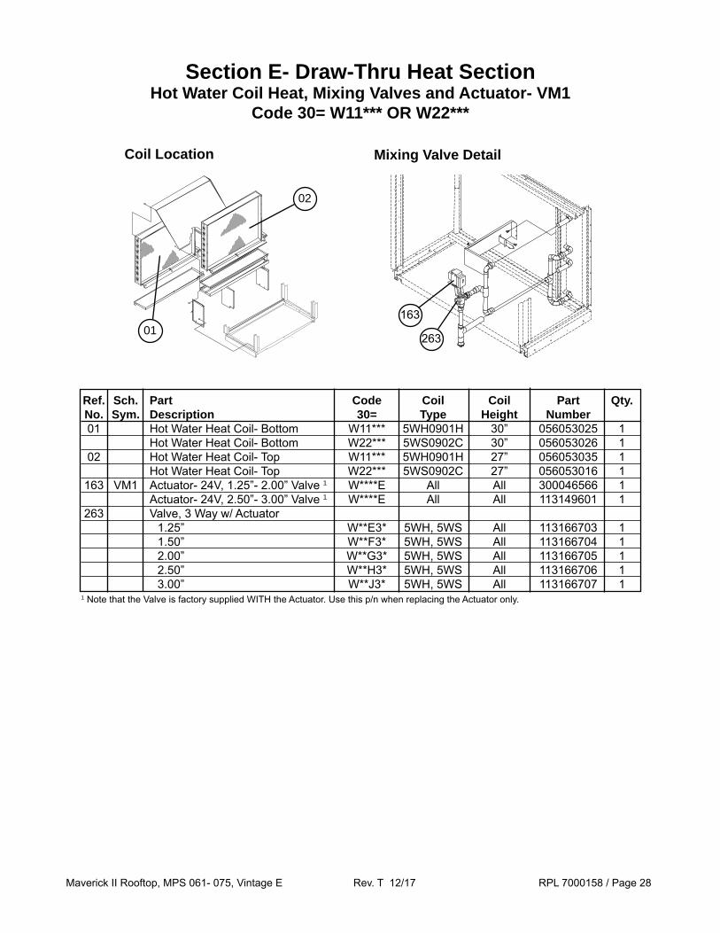
Section E- Draw-Thru Heat SectionHot Water Coil Heat, Mixing Valves and Actuator- VM1
Code 30= W11*** OR W22***
Ref. Sch. Part Code Coil Coil Part Qty. No. Sym. Description 30= Type Height Number 01 Hot Water Heat Coil- Bottom W11*** 5WH0901H 30” 056053025 1 Hot Water Heat Coil- Bottom W22*** 5WS0902C 30” 056053026 1 02 Hot Water Heat Coil- Top W11*** 5WH0901H 27” 056053035 1 Hot Water Heat Coil- Top W22*** 5WS0902C 27” 056053016 1 163 VM1 Actuator- 24V, 1.25”- 2.00” Valve 1 W****E All All 300046566 1 Actuator- 24V, 2.50”- 3.00” Valve 1 W****E All All 113149601 1 263 Valve, 3 Way w/ Actuator 1.25” W**E3* 5WH, 5WS All 113166703 1 1.50” W**F3* 5WH, 5WS All 113166704 1 2.00” W**G3* 5WH, 5WS All 113166705 1 2.50” W**H3* 5WH, 5WS All 113166706 1 3.00” W**J3* 5WH, 5WS All 113166707 1
Coil Location Mixing Valve Detail
1 Note that the Valve is factory supplied WITH the Actuator. Use this p/n when replacing the Actuator only.

Maverick II Rooftop, MPS 061- 075, Vintage E Rev. T 12/17 RPL 7000158 / Page 29
Section F- Supply Air SectionAir Foil Fan- Double Width
Code 31= 30A1, 30A3
Ref. Part Part Qty. No Description Number 1 Motor- see table 3 pages after next 2 Housing Assy- Blower 055527702 1 Inlet Funnel Only 031940902 2 3 Wheel, Fan- Single Inlet Single Width CW 066543203 1 4 Wheel, Fan- Single Inlet Single Width CCW 066543204 1 5 Screw Adjust Assembly 055528202 2 11 Shaft- 2.438” Diameter 055582902 1 15 Motor Mount Assembly 056104501 1 16 Angle- Motor Mount 055514201 1 17 Holddown 041272900 1 18 Angle, Clamping 055576601 1 21 Key- Fan 9.25” Long X 5/8” Diameter 023221614 1 22 Key- Sheave 6.50” Long X 5/8” Diameter 023221610 1 25 Bearing- Ball 2.437” Bore 020648655 2
21 4
2
18
1
17
17
16 5
1125
22
15
Wheel Detail(When FACING
Discharge opening)
3

Maverick II Rooftop, MPS 061- 075, Vintage E Rev. T 12/17 RPL 7000158 / Page 30
Section F- Supply Air SectionAir Foil Fan- Single Width
Code 31= 40B1, 40B3
Ref. Part Part Qty. No. Description Number 1 Motor- see table 2 pages after next 3 Wheel, Fan- Single Inlet/Single Width 066543243 1 4 Inlet Funnel Assembly 031940905 1 5 Screw Adjust Assembly 055528203 2 11 Shaft 2.188” Diameter 055615902 1 15 Mount Assembly-Motor 056104501 1 16 Angle -Motor Mount 055514201 1 17 Angle, Clamping 055512701 2 21 Key- Fan, 4.25” Long X 1/2” Diameter 023221519 1 22 Key- Fan, 5.50” Long X 1/2” Diameter 023221513 1 24 Tubing- Plastic 021136790 1 25 Bearing- Ball 2.187” Bore 020648656 1 26 Fitting- 1/4” OD X 1/8” MPT 027674000 1 27 Fitting- 1/4” OD X 1/8” FPT 027674100 1 38 Bearing- Ball 2.187” Bore 020648656 1
243
5
1
11
16
2215
38
4
21
27
25 26
17

Maverick II Rooftop, MPS 061- 075, Vintage E Rev. T 12/17 RPL 7000158 / Page 31
Section F- Supply Air SectionFan Mounts- 30” Airfoil Double Width Fan
Code 31= 30A1, 30A3
161 162
163 164
188
189
181
121 Ref. Fan Motor Part Part Qty. No. HP Description Number 121 All Mount 251783301 4 161 5 Spring Mount- Purple 251784701 1 7.5- 20 Spring Mount- Brown 251784801 1 25- 50 Spring Mount- Red 251784901 1 162 All Spring Mount- Purple 251784701 1 163 5, 7.5 Spring Mount- Brown 251784801 1 10- 20 Spring Mount- Red 251784901 1 25- 50 Spring Mount- Red/Black 251785001 1 164 All Spring Mount- Brown 251784801 1 181 All Nut 111056301 20 188 All Nut 040500002 4 189 All Screw 112047201 20
Seismic Spring (Code 31= 30A3)
Ref. Fan Motor Part Part Qty. No. HP Description Number 21 All Channel- Mount Support 098316001 4 61 3, 5 Rubber Mount- Black 021639704 1 7.5- 50 Rubber Mount- Red 021639701 1 62 All Rubber Mount- Black 021639704 1 63 3- 30 Rubber Mount- Red 021639701 1 40, 50 Rubber Mount- Green 021639703 1 64 3- 15 Rubber Mount- Black 021639704 1 20- 50 Rubber Mount- Red 021639701 1 81 All Nut 059992201 8 89 All Screw 112047201 8 91 All Nut- 1/2-13 032333305 12 92 All Screw- Cap, 1/2-13 X 1” 040499501 8 93 All Washer- Plain, 1/2” 048164812 8
Rubber Mounts (Code 31= 30A1)92
93
89
81 91
21
61 62
63 64
Rubber Mounts
Spring Mounts
Mount Locations61161 or
63163 or
16262 or
16464 or
91
Seismic strap used only when Code 31= 30A3.
Maverick II Rooftop, MPS 061- 075, Vintage E Rev. T 12/17 RPL 7000158 / Page 32
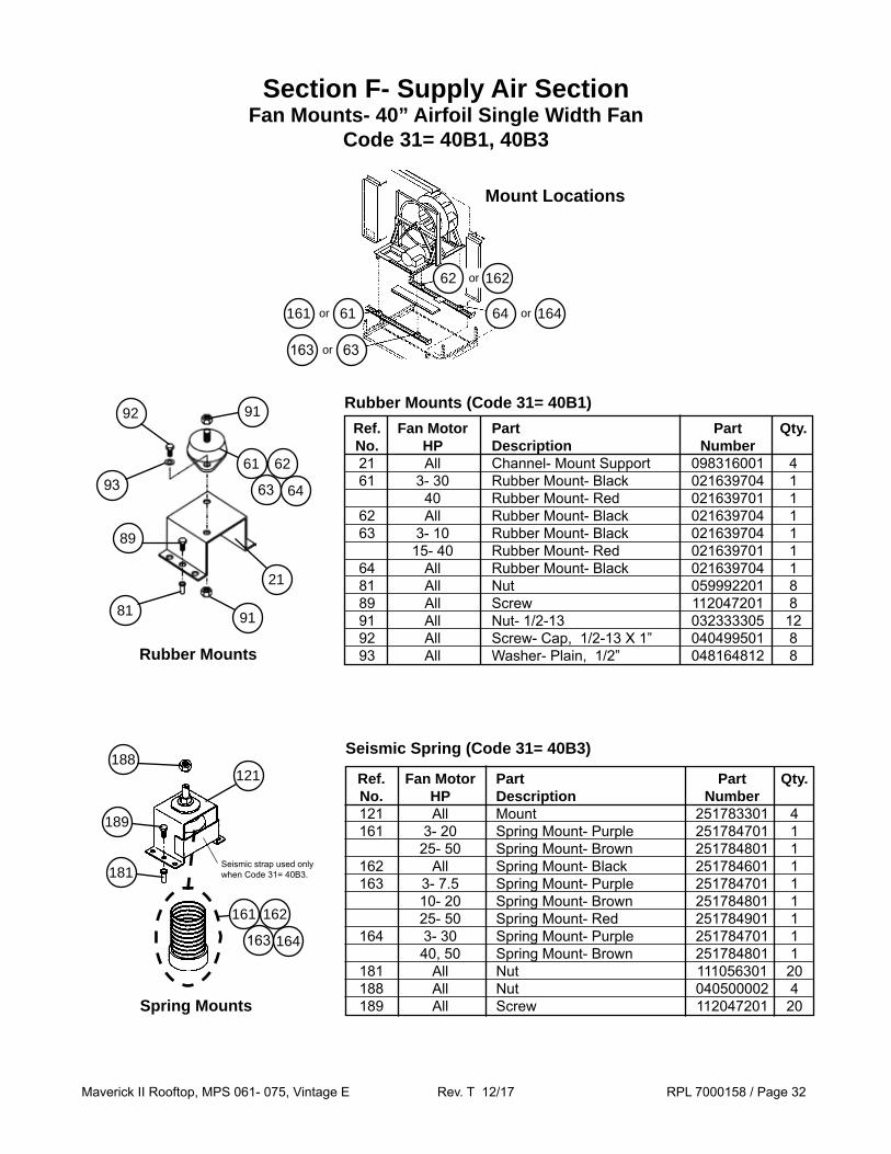
Section F- Supply Air SectionFan Mounts- 40” Airfoil Single Width Fan
Code 31= 40B1, 40B3
Ref. Fan Motor Part Part Qty. No. HP Description Number 121 All Mount 251783301 4 161 3- 20 Spring Mount- Purple 251784701 1 25- 50 Spring Mount- Brown 251784801 1 162 All Spring Mount- Black 251784601 1 163 3- 7.5 Spring Mount- Purple 251784701 1 10- 20 Spring Mount- Brown 251784801 1 25- 50 Spring Mount- Red 251784901 1 164 3- 30 Spring Mount- Purple 251784701 1 40, 50 Spring Mount- Brown 251784801 1 181 All Nut 111056301 20 188 All Nut 040500002 4 189 All Screw 112047201 20
Seismic Spring (Code 31= 40B3)
Ref. Fan Motor Part Part Qty. No. HP Description Number 21 All Channel- Mount Support 098316001 4 61 3- 30 Rubber Mount- Black 021639704 1 40 Rubber Mount- Red 021639701 1 62 All Rubber Mount- Black 021639704 1 63 3- 10 Rubber Mount- Black 021639704 1 15- 40 Rubber Mount- Red 021639701 1 64 All Rubber Mount- Black 021639704 1 81 All Nut 059992201 8 89 All Screw 112047201 8 91 All Nut- 1/2-13 032333305 12 92 All Screw- Cap, 1/2-13 X 1” 040499501 8 93 All Washer- Plain, 1/2” 048164812 8
Rubber Mounts (Code 31= 40B1)
Mount Locations
61161 or
63163 or
16262 or
16464 or
92
93
89
81 91
21
61 62
63 64
Rubber Mounts
91
161 162
163 164
188
189
181
121
Spring Mounts
Seismic strap used only when Code 31= 40B3.

Maverick II Rooftop, MPS 061- 075, Vintage E Rev. T 12/17 RPL 7000158 / Page 33
Section F- Supply Air SectionSupply Air Fan Motors
H.P. Motor H.P. Unit ODP PrEff. Code 32= Voltage C32= *JY C09= 12 3 H** 208/60/3 065817100 5 J** 208/60/3 065817200 7.5 K* 208/60/3 065817300 10 L** 208/60/3 065817400 15 M** 208/60/3 065817500 20 N** 208/60/3 065817600 25 P** 208/60/3 065817700 30 Q** 208/60/3 205066500 40 R** 208/60/3 205067100 50 S** 208/60/3 205067500 C09= 29 3 H** 230/60/3 065818100 5 J** 230/60/3 065818200 7.5 K** 230/60/3 065818300 10 L** 230/60/3 065818400 15 M** 230/60/3 065818500 20 N** 230/60/3 065818600 25 P** 230/60/3 065818700 30 Q** 230/60/3 205066600 40 R** 230/60/3 205067200 50 S** 230/60/3 205067600 C09= 27 3 H** 460/60/3 065818100 5 J** 460/60/3 065818200 7.5 K** 460/60/3 065818300 10 L** 460/60/3 065818400 15 M** 460/60/3 065818500 20 N** 460/60/3 065818600 25 P** 460/60/3 065818700 30 Q** 460/60/3 205066600 40 R** 460/60/3 205067200 50 S** 460/60/3 205067600 C09= 37 3 H** 575/60/3 046511700 5 J** 575/60/3 205168900 7.5 K** 575/60/3 205168800 10 L** 575/60/3 205168600 15 M** 575/60/3 205166600 20 N** 575/60/3 205166800 25 P** 575/60/3 205166900 30 Q** 575/60/3 205066700 40 R** 575/60/3 205067300 50 S** 575/60/3 205091800

Maverick II Rooftop, MPS 061- 075, Vintage E Rev. T 12/17 RPL 7000158 / Page 34
Section F- Supply Air SectionInverters
Motor Horsepower 2 3 5 7.5 10 15 20 25 30 40 50
Part Number 193475806 1 1 193475822 1 1 193456301 2, 3 1 193475807 1 1 193475823 1 1 193456303 2, 3 1 193475809 1 1 193475825 1 1 193456304 2, 3 1 193475810 1 1 193475826 1 1 193456305 2, 3 1 193475811 1 1 193475827 1 1 193456306 2, 3 1 193475812 1 1 193475828 1 1 193456307 2, 3 1 193475813 1 1 193475829 1 1 193456308 2, 3 1 193475814 1 1 193475830 1 1 349956647 4 1 193475815 1 1 193475831 1 1 349956648 4 1 193475816 1 1 193475832 1 1 349956649 4 1 349956617 4 1 193475883 1 1 349956650 4 1
208/
230V
460V
575V
208
/230
V
460V
575V
208
/230
V
460V
575V
208
/230
V
460V
575V
208
/230
V
460V
575V
208
/230
V
460V
575V
208
/230
V
460V
575V
208
/230
V
460V
575V
208
/230
V
460V
575V
208/
230V
460V
575V
208/
230V
460V
575V
Code 15= S: MD2, MD3, MD6
1 In 2010 the original ATV21 drives were replaced with ATV212 drives as listed above. These new drives are drop in replacements with the exception of the Remote Keypad and Communication Cards. The ATV21 Remote Keypad is p/n 349958801. The ATV21 Lonworks communication card is p/n 349927103. The ATV212 Remote Keypad is p/n 349958805 and the Remote Keypad Mounting kit is p/n 349958803. The ATV212 Lonworks communication card is p/n 193482601. All other ATV212 communication cards are integral to the VFD and are not available separately. Note that since the original ATV21 drives are obsolete and unavailable, when at zero stock, repair parts are also not available. If an obsolete ATV21 part fails, the entire drive must be replaced.
2 MD3 Remote Keypad p/n is 349958802.3 For 575V units with an MD3 Inverter and Motor 20 HP or smaller a Line Reactor will be automatically installed. See the table
one page after next for Line Reactor part numbers.4 MD6 Remote Keypad p/n is 349958805 plus Mount p/n 349958803.

Maverick II Rooftop, MPS 061- 075, Vintage E Rev. T 12/17 RPL 7000158 / Page 35
Section F- Supply Air SectionInverters
Code 15= B: MD4, MD5 1
Motor Horsepower 2 3 5 7.5 10 15 20 25 30 40 50
Part Number 193552245 1 193552295 1 193552397 1 193552246 1 193552296 1 193552326 1 193552215 1 193552202 1 193552327 1 193552216 1 193552203 1 193552328 1 193552217 1 193552204 1 193552329 1 193552218 1 193552205 1 193552330 1 193552319 1 193552206 1 193552331 1 193552320 1 193552207 1 193552332 1 193552321 1 193552208 1 193552333 1 193552322 1 193552309 1 193552334 1 193552323 1 193552310 1 193552335 1
208/
230V
460V
575V
208
/230
V
460V
575V
208
/230
V
460V
575V
208
/230
V
460V
575V
208
/230
V
460V
575V
208
/230
V
460V
575V
208
/230
V
460V
575V
208
/230
V
460V
575V
208
/230
V
460V
575V
208
/230
V
460V
575V
208
/230
V
460V
575V
1 The replacement VFD Keypad for MD4 & MD5 Inverters is p/n is 300040924.

Maverick II Rooftop, MPS 061- 075, Vintage E Rev. T 12/17 RPL 7000158 / Page 36
Section F- Supply Air SectionLine Reactors 1
Motor Horsepower 2 3 5 7.5 10 15 20 25 30 40 50
Part Number 073323541 1 073323502 1 349964953 2 1 1 073323517 1 073323533 1 073323518 1 073323503 1 349964929 2 1 073323519 1 073323504 1 3499649322 1 073323520 1 073323505 1 349964927 2 1 073323511 1 073323506 1 349964930 2 1 073323512 1 073323534 1 349964931 2 1 073323521 1 073323507 1 349964926 2 1 073323522 1 073323508 1 349964954 2 1 073323523 1 073323509 1 349964955 2 1 073323535 3 1 3
208/
230V
460V
575V
208
/230
V
460V
575V
208
/230
V
460V
575V
208
/230
V
460V
575V
208
/230
V
460V
575V
208
/230
V
460V
575V
208
/230
V
460V
575V
208
/230
V
460V
575V
208
/230
V
460V
575V
208/
230V
460V
575V
208/
230V
460V
575V
1 Line Reactors are optional except for 575V units (Code 09= 37), when Code 15= S, AND the Inverter is 20HP or smaller. 2 These are 5% impedance line reactors. Some units may have 3% impedance line reactors, the 5% may be used in their place. Due to
dimensional differences, minor field modifications may be required for proper installation.3 Not available for this HP and voltage.

Maverick II Rooftop, MPS 061- 075, Vintage E Rev. T 12/17 RPL 7000158 / Page 37
Section F- Supply Air SectionSection Mounted Controls- PC7, HL22, EFT, OAT, DAT
67
Ref. Part Part Qty. No. Description Number 67 T-stat- HL22 Hi Limit 047938801 1
HL22- Gas Heat Hi Limit SwitchCode 04= A
Ref. Part Part Qty. No. Description Number 7 OA Temp. Sensor- OAT 193414602 1
Outdoor Air Temperature Sensor- OAT7
8
OAT
DAT
Ref. Part Part Qty. No. Description Number 8 DA Temp. Sensor- DAT 193414602 1
Discharge Air Temperature Sensor- DAT
5
EFT
Ref. Part Part Qty. No. Description Number 5 EF Temp. Sensor- EFT 193414602 1
Entering Fan Temperature Sensor- EFT
PC7- Proof of Airflow Pressure Control
19
15
20
Ref. Part Part Qty. No. Description Number 15 Bracket 1 1 19 Pressure Control- PC7 1 1 20 Pneumatic Fitting 1 11 In mid 2012 the design of PC7 was changed. Units equipped
with the old style PC7 require Retrofit Kit 910122413 for proper installation as old and new parts are NOT interchangeable. The Switch only is p/n 910115489, the Pneumatic Fitting is p/n 910122414, and the Support Bracket is p/n 910122290.
Maverick II Rooftop, MPS 061- 075, Vintage E Rev. T 12/17 RPL 7000158 / Page 38
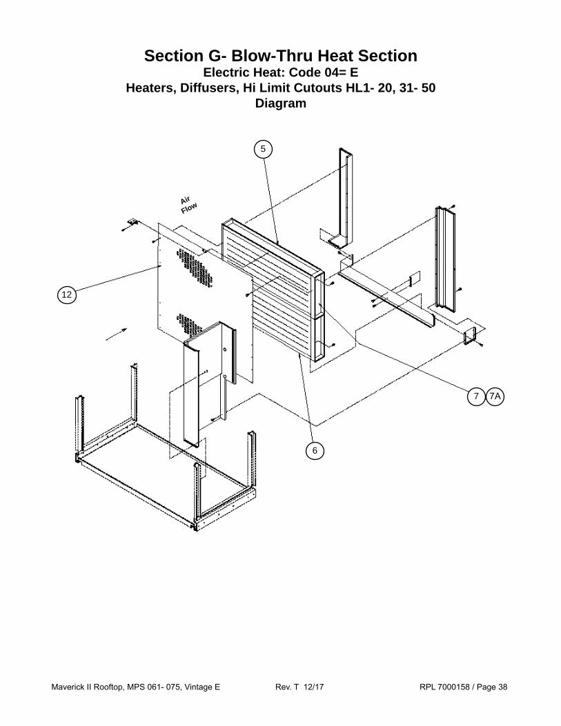
Section G- Blow-Thru Heat SectionElectric Heat: Code 04= E
Heaters, Diffusers, Hi Limit Cutouts HL1- 20, 31- 50Diagram
6
5
12
7 7A
Air
Flow
Maverick II Rooftop, MPS 061- 075, Vintage E Rev. T 12/17 RPL 7000158 / Page 39
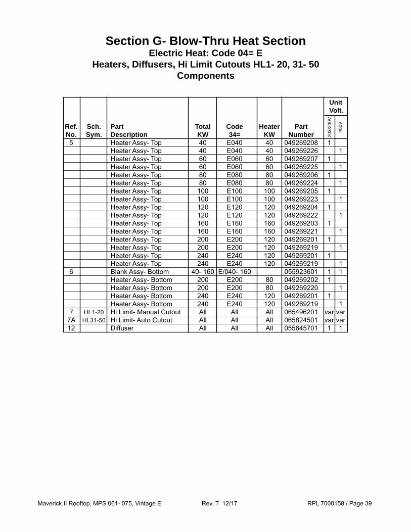
Section G- Blow-Thru Heat SectionElectric Heat: Code 04= E
Heaters, Diffusers, Hi Limit Cutouts HL1- 20, 31- 50Components
Unit Volt. Ref. Sch. Part Total Code Heater Part No. Sym. Description KW 34= KW Number 5 Heater Assy- Top 40 E040 40 049269208 1 Heater Assy- Top 40 E040 40 049269226 1 Heater Assy- Top 60 E060 60 049269207 1 Heater Assy- Top 60 E060 60 049269225 1 Heater Assy- Top 80 E080 80 049269206 1 Heater Assy- Top 80 E080 80 049269224 1 Heater Assy- Top 100 E100 100 049269205 1 Heater Assy- Top 100 E100 100 049269223 1 Heater Assy- Top 120 E120 120 049269204 1 Heater Assy- Top 120 E120 120 049269222 1 Heater Assy- Top 160 E160 160 049269203 1 Heater Assy- Top 160 E160 160 049269221 1 Heater Assy- Top 200 E200 120 049269201 1 Heater Assy- Top 200 E200 120 049269219 1 Heater Assy- Top 240 E240 120 049269201 1 Heater Assy- Top 240 E240 120 049269219 1 6 Blank Assy- Bottom 40- 160 E/040- 160 055923601 1 1 Heater Assy- Bottom 200 E200 80 049269202 1 Heater Assy- Bottom 200 E200 80 049269220 1 Heater Assy- Bottom 240 E240 120 049269201 1 Heater Assy- Bottom 240 E240 120 049269219 1 7 HL1-20 Hi Limit- Manual Cutout All All All 065496201 var var 7A HL31-50 Hi Limit- Auto Cutout All All All 065824501 var var 12 Diffuser All All All 055645701 1 1
208/
230V
460V

Maverick II Rooftop, MPS 061- 075, Vintage E Rev. T 12/17 RPL 7000158 / Page 40
Section G- Blow-Thru Heat SectionElectric Heat: Code 04= EElectric Heat Control Box
Diagrams & Components- (02/2013 & Earlier)
208/230V20KW- 160KW
460/575V20KW- 160KW
460/575V200KW
FB33 FB37 FB32 FB36 FB31 FB35
M33 M37 M32 M36 M31 M35
M34 M38
FB34 FB38
HS3
DS3or
PB3
FB33 FB32 FB31
FB34
M33
M34
M32 M31
HS3
DS3or
PB3
TB11
FB33 FB32 FB31
FB41
M33
M41
M32 M31
HS3
DS3or
PB3
FB42
M42
TB11
TB11
PB31 PB31 PB31
Sch. Part Disconnect Switch Component Sym. Description Amps Switch Handle Shaft Lug Kit DS3 Disconnect Switch 100 Amp 349935125 349935523 2 349962211 349938001 Disconnect Switch 150 Amp 349935126 349935533 2 349962212 349938001 Disconnect Switch 250 Amp 349935226 349935533 2 349962212 349938001 Disconnect Switch 400 Amp 349935325 349935622 2 349962213 349938002 Disconnect Switch 600 Amp 193438205 3 3, 4 349962243 3 349938002
DS3- Disconnect Switch 1
1 Disconnects are sized according to various unit specifications. Check installed switch to verify the correct DS3 size, or contact Daikin Applied with model and serial number information so that the required part(s) can be identified.
2 Includes Mechanism (except 600A switch, see footnote #4).3 Note that the original disconnect switch is obsolete. Due to dimensional differences minor field modifications may be required for
proper installation. 4 Handle only p/n 349961102; Mechanism only p/n 193455001; Shaft only p/n 349961403.
Maverick II Rooftop, MPS 061- 075, Vintage E Rev. T 12/17 RPL 7000158 / Page 41
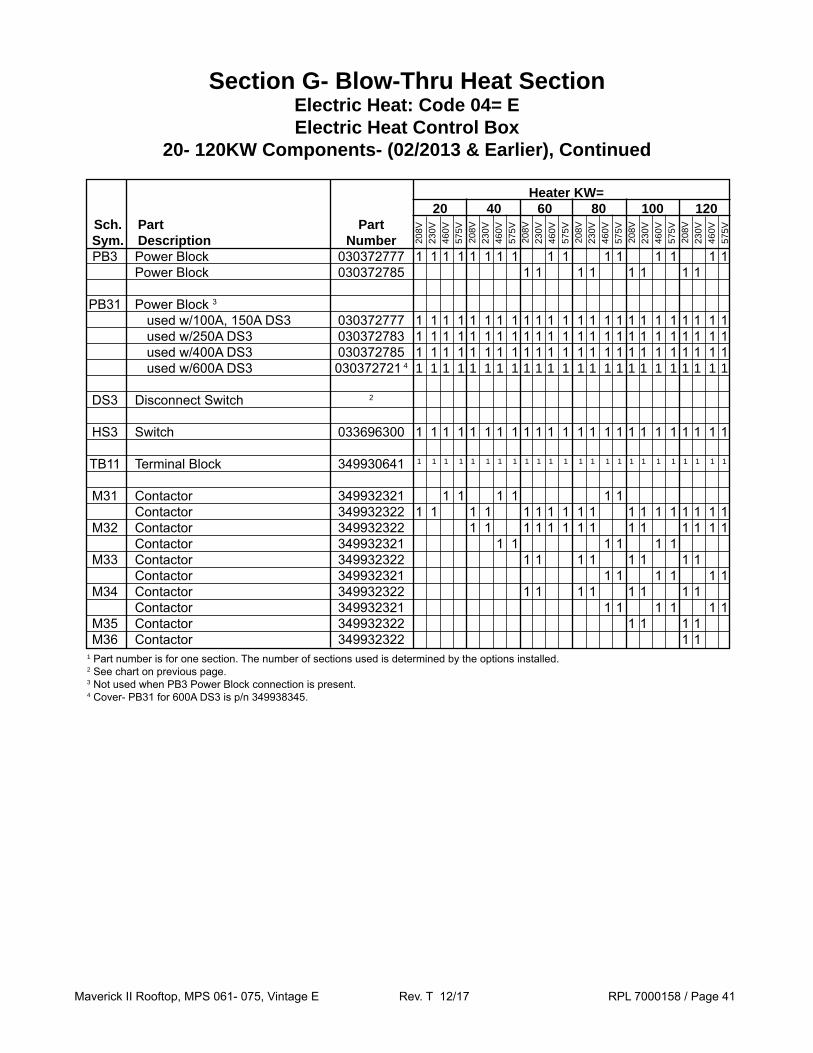
Heater KW= 20 40 60 80 100 120 Sch. Part Part Sym. Description Number PB3 Power Block 030372777 1 1 1 1 1 1 1 1 1 1 1 1 1 1 1 1 Power Block 030372785 1 1 1 1 1 1 1 1
PB31 Power Block 3 used w/100A, 150A DS3 030372777 1 1 1 1 1 1 1 1 1 1 1 1 1 1 1 1 1 1 1 1 1 1 1 1 used w/250A DS3 030372783 1 1 1 1 1 1 1 1 1 1 1 1 1 1 1 1 1 1 1 1 1 1 1 1 used w/400A DS3 030372785 1 1 1 1 1 1 1 1 1 1 1 1 1 1 1 1 1 1 1 1 1 1 1 1 used w/600A DS3 030372721 4 1 1 1 1 1 1 1 1 1 1 1 1 1 1 1 1 1 1 1 1 1 1 1 1
DS3 Disconnect Switch 2
HS3 Switch 033696300 1 1 1 1 1 1 1 1 1 1 1 1 1 1 1 1 1 1 1 1 1 1 1 1
TB11 Terminal Block 349930641 1 1 1 1 1 1 1 1 1 1 1 1 1 1 1 1 1 1 1 1 1 1 1 1
M31 Contactor 349932321 1 1 1 1 1 1 Contactor 349932322 1 1 1 1 1 1 1 1 1 1 1 1 1 1 1 1 1 1 M32 Contactor 349932322 1 1 1 1 1 1 1 1 1 1 1 1 1 1 Contactor 349932321 1 1 1 1 1 1 M33 Contactor 349932322 1 1 1 1 1 1 1 1 Contactor 349932321 1 1 1 1 1 1 M34 Contactor 349932322 1 1 1 1 1 1 1 1 Contactor 349932321 1 1 1 1 1 1 M35 Contactor 349932322 1 1 1 1 M36 Contactor 349932322 1 1
208V
230V
460V
575V
208
V23
0V46
0V57
5V 2
08V
230V
460V
575V
208
V23
0V46
0V57
5V 2
08V
230V
460V
575V
208
V23
0V46
0V57
5V
1 Part number is for one section. The number of sections used is determined by the options installed.2 See chart on previous page.3 Not used when PB3 Power Block connection is present.4 Cover- PB31 for 600A DS3 is p/n 349938345.
Section G- Blow-Thru Heat SectionElectric Heat: Code 04= EElectric Heat Control Box
20- 120KW Components- (02/2013 & Earlier), Continued

Maverick II Rooftop, MPS 061- 075, Vintage E Rev. T 12/17 RPL 7000158 / Page 42
Heater KW= 20 40 60 80 100 120 Sch. Part Part Sym. Description Number FB31 Fuse Block 023780229 1 1 1 1 1 1 1 1 1 1 1 1 Fuse Block 023780225 1 1 1 1 1 1 Fuse Block 023780230 1 1 1 1 1 1 FB32 Fuse Block 023780229 1 1 1 1 1 1 1 1 1 1 Fuse Block 023780225 1 1 1 1 1 1 Fuse Block 023780230 1 1 1 1 FB33 Fuse Block 023780229 1 1 1 1 1 1 1 1 Fuse Block 023780225 1 1 1 1 1 1 FB34 Fuse Block 023780229 1 1 1 1 1 1 1 1 Fuse Block 023780225 1 1 1 1 1 1 FB35 Fuse Block 023780229 1 1 1 1 FB36 Fuse Block 023780229 1 1
F31 Fuse- FB31 025860514 3 3 3 3 3 3 3 3 3 3 Fuse- FB31 025860511 3 Fuse- FB31 025860512 3 Fuse- FB31 025860409 3 3 3 Fuse- FB31 025860408 3 3 3 Fuse- FB31 025860412 3 Fuse- FB31 025860411 3 Fuse- FB31 025860414 3 3 Fuse- FB31 025860413 3 3 F32 Fuse- FB32 025860514 3 3 3 3 3 3 3 3 Fuse- FB32 025860511 3 Fuse- FB32 025860512 3 Fuse- FB32 025860409 3 3 3 Fuse- FB32 025860408 3 3 3 Fuse- FB32 025860412 3 Fuse- FB32 025860411 3 Fuse- FB32 025860414 3 Fuse- FB32 025860413 3 F33 Fuse- FB33 025860511 3 Fuse- FB33 025860512 3 Fuse- FB33 025860514 3 3 3 3 3 3 Fuse- FB33 025860409 3 3 3 Fuse- FB33 025860408 3 3 3 F34 Fuse- FB34 025860511 3 Fuse- FB34 025860512 3 Fuse- FB34 025860514 3 3 3 3 3 3 Fuse- FB34 025860409 3 3 3 Fuse- FB34 025860408 3 3 3 F35 Fuse- FB35 025860514 3 3 3 3 F36 Fuse- FB36 025860514 3 3
208V
230V
460V
575V
208
V23
0V46
0V57
5V 2
08V
230V
460V
575V
208
V23
0V46
0V57
5V 2
08V
230V
460V
575V
208
V23
0V46
0V57
5V
Section G- Blow-Thru Heat SectionElectric Heat: Code 04= EElectric Heat Control Box
20- 120KW Components- (02/2013 & Earlier), Continued
Maverick II Rooftop, MPS 061- 075, Vintage E Rev. T 12/17 RPL 7000158 / Page 43
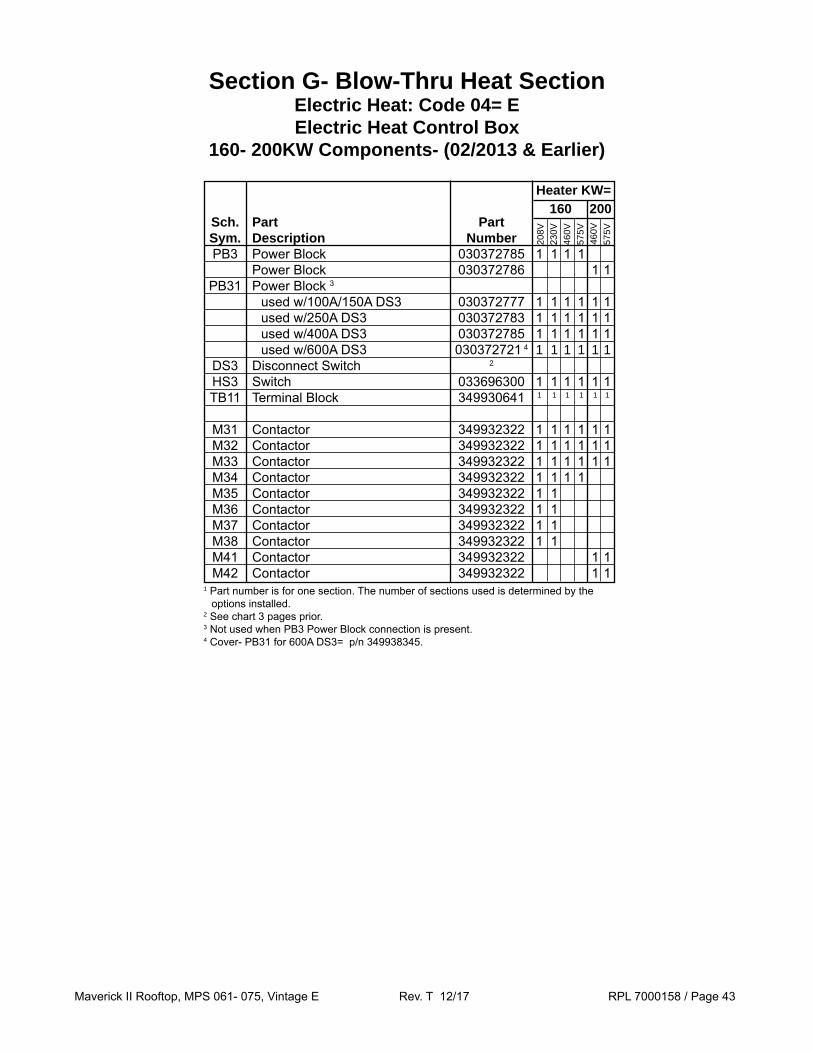
Heater KW= 160 200 Sch. Part Part Sym. Description Number PB3 Power Block 030372785 1 1 1 1 Power Block 030372786 1 1 PB31 Power Block 3 used w/100A/150A DS3 030372777 1 1 1 1 1 1 used w/250A DS3 030372783 1 1 1 1 1 1 used w/400A DS3 030372785 1 1 1 1 1 1 used w/600A DS3 030372721 4 1 1 1 1 1 1 DS3 Disconnect Switch 2
HS3 Switch 033696300 1 1 1 1 1 1 TB11 Terminal Block 349930641 1 1 1 1 1 1
M31 Contactor 349932322 1 1 1 1 1 1 M32 Contactor 349932322 1 1 1 1 1 1 M33 Contactor 349932322 1 1 1 1 1 1 M34 Contactor 349932322 1 1 1 1 M35 Contactor 349932322 1 1 M36 Contactor 349932322 1 1 M37 Contactor 349932322 1 1 M38 Contactor 349932322 1 1 M41 Contactor 349932322 1 1 M42 Contactor 349932322 1 1
208V
230V
460V
575V
460
V57
5V
1 Part number is for one section. The number of sections used is determined by the options installed.
2 See chart 3 pages prior.3 Not used when PB3 Power Block connection is present.4 Cover- PB31 for 600A DS3= p/n 349938345.
Section G- Blow-Thru Heat SectionElectric Heat: Code 04= EElectric Heat Control Box
160- 200KW Components- (02/2013 & Earlier)

Maverick II Rooftop, MPS 061- 075, Vintage E Rev. T 12/17 RPL 7000158 / Page 44
Heater KW= 160 200 Sch. Part Part Sym. Description Number FB31 Fuse Block 023780229 1 1 Fuse Block 023780230 1 1 1 1 FB32 Fuse Block 023780229 1 1 Fuse Block 023780225 Fuse Block 023780230 1 1 1 1 FB33 Fuse Block 023780229 1 1 Fuse Block 023780230 1 1 1 1 FB34 Fuse Block 023780229 1 1 Fuse Block 023780230 1 1 FB35 Fuse Block 023780229 1 1 FB36 Fuse Block 023780229 1 1 FB37 Fuse Block 023780229 1 1 FB38 Fuse Block 023780229 1 1 FB41 Fuse Block 023780230 1 1 FB42 Fuse Block 023780230 1 1
F31 Fuse- FB31 025860514 3 3 Fuse- FB31 025860414 3 3 Fuse- FB31 025860413 3 3 F32 Fuse- FB32 025860514 3 3 Fuse- FB32 025860414 3 3 Fuse- FB32 025860413 3 3 F33 Fuse- FB33 025860514 3 3 Fuse- FB33 025860414 3 3 Fuse- FB33 025860413 3 3 F34 Fuse- FB34 025860514 3 3 Fuse- FB34 025860414 3 Fuse- FB34 025860413 3 F35 Fuse- FB35 025860514 3 3 F36 Fuse- FB36 025860514 3 3 F37 Fuse- FB37 025860514 3 3 F38 Fuse- FB38 025860514 3 3 F41 Fuse- FB41 025860414 3 Fuse- FB41 025860413 3 F42 Fuse- FB42 025860414 3 Fuse- FB42 025860413 3
208V
230V
460V
575V
460
V57
5V
Section G- Blow-Thru Heat SectionElectric Heat: Code 04= EElectric Heat Control Box
160- 200KW Components- (02/2013 & Earlier), Continued

Maverick II Rooftop, MPS 061- 075, Vintage E Rev. T 12/17 RPL 7000158 / Page 45
Section G- Blow-Thru Heat SectionElectric Heat: Code 04= EElectric Heat Control Box
Diagrams & Components- (03/2013 & Later)
208/230V20KW- 160KW
460/575V20KW- 160KW
460/575V200KW
FB33 FB37 FB32 FB36 FB31 FB35
M33 M37 M32 M36 M31 M35
M34 M38
FB34 FB38
HS3
DS3or
PB3
FB33 FB32 FB31
FB34
M33
M34
M32 M31
HS3
DS3or
PB3
TB11
FB33 FB32 FB31
FB41
M33
M41
M32 M31
HS3
DS3or
PB3
FB42
M42
TB11
TB11
PB31 PB31 PB31
Sch. Part Disconnect Switch Component Sym. Description Switch Mechanism Handle Shaft Lugs DS3 Disconnect Switch- 100A 193444703 Not Used 193422102 193596420 2 Not Used Disconnect Switch- 150A 193585101 193550801 193422102 193596420 2 193553301 4
Disconnect Switch- 250A 193551601 193551001 193595701 300049193 3 193553801 4
Disconnect Switch- 400A 193551701 193551001 193595701 300049193 3 193554001 4
Disconnect Switch- 600A 193551801 193551001 193595701 300049193 3 193554101 4
DS3- Disconnect Switch 1
1 Disconnects are sized according to various unit specifications. Check installed switch to verify the correct DS3 size, or contact Daikin Applied with model and serial number information so that the required part(s) can be identified.
2 This Shaft is 14.25” OAL and is designed to be cut to length in the field.3 This Shaft is 7.21” (183mm) OAL and is designed to be cut to length in the field. For a 19.69” (500mm) OAL use p/n 300040299.4 Three Lugs are included with each p/n.

Maverick II Rooftop, MPS 061- 075, Vintage E Rev. T 12/17 RPL 7000158 / Page 46
Heater KW= 20 40 60 80 100 120 Sch. Part Part Sym. Description Number PB3 Power Block 175A 030372777 1 1 1 1 1 1 1 1 1 1 1 1 1 1 1 1 Power Block 420A 030372785 1 1 1 1 1 1 1 1
PB31 Power Block 3 175A 030372777 1 1 1 1 1 1 1 1 1 1 1 1 1 1 1 1 Power Block 3 420A 030372785 1 1 1 1 1 1 1 1
DS3 Disconnect Switch 2
HS3 Switch 033696300 1 1 1 1 1 1 1 1 1 1 1 1 1 1 1 1 1 1 1 1 1 1 1 1
TB11 Terminal Block 349930641 1 1 1 1 1 1 1 1 1 1 1 1 1 1 1 1 1 1 1 1 1 1 1 1
M31 Contactor 40A 193591601 1 1 1 1 1 1 1 1 1 1 1 1 1 1 1 1 1 1 Contactor 12A 193592005 1 1 1 1 1 1 M32 Contactor 40A 193591601 1 1 1 1 1 1 1 1 1 1 1 1 1 1 Contactor 12A 193592005 1 1 1 1 1 1 M33 Contactor 40A 193591601 1 1 1 1 1 1 1 1 Contactor 12A 193592005 1 1 1 1 1 1 M34 Contactor 40A 193591601 1 1 1 1 1 1 1 1 Contactor 12A 193592005 1 1 1 1 1 1 M35 Contactor 40A 193591601 1 1 1 1 M36 Contactor 40A 193591601 1 1
208V
230V
460V
575V
208
V23
0V46
0V57
5V 2
08V
230V
460V
575V
208
V23
0V46
0V57
5V 2
08V
230V
460V
575V
208
V23
0V46
0V57
5V
Section G- Blow-Thru Heat SectionElectric Heat: Code 04= EElectric Heat Control Box
20- 120KW Components- (03/2013 & Later), Continued
1 Part number is for one section. The number of sections used is determined by the options installed.2 See the chart on the previous page.3 Not used when PB3 Power Block connection is present.

Maverick II Rooftop, MPS 061- 075, Vintage E Rev. T 12/17 RPL 7000158 / Page 47
Heater KW= 20 40 60 80 100 120 Sch. Part Part Sym. Description Number FB31 Fuse Block 023780229 1 1 1 1 1 1 1 1 1 1 1 1 Fuse Block 023780225 1 1 1 1 1 1 Fuse Block 023780230 1 1 1 1 1 1 FB32 Fuse Block 023780229 1 1 1 1 1 1 1 1 1 1 Fuse Block 023780225 1 1 1 1 1 1 Fuse Block 023780230 1 1 1 1 FB33 Fuse Block 023780229 1 1 1 1 1 1 1 1 Fuse Block 023780225 1 1 1 1 1 1 FB34 Fuse Block 023780229 1 1 1 1 1 1 1 1 Fuse Block 023780225 1 1 1 1 1 1 FB35 Fuse Block 023780229 1 1 1 1 FB36 Fuse Block 023780229 1 1
F31 Fuse- FB31 025860514 3 3 3 3 3 3 3 3 3 3 Fuse- FB31 025860511 3 Fuse- FB31 025860512 3 Fuse- FB31 025860409 3 3 3 Fuse- FB31 025860408 3 3 3 Fuse- FB31 025860412 3 Fuse- FB31 025860411 3 Fuse- FB31 025860414 3 3 Fuse- FB31 025860413 3 3 F32 Fuse- FB32 025860514 3 3 3 3 3 3 3 3 Fuse- FB32 025860511 3 Fuse- FB32 025860512 3 Fuse- FB32 025860409 3 3 3 Fuse- FB32 025860408 3 3 3 Fuse- FB32 025860412 3 Fuse- FB32 025860411 3 Fuse- FB32 025860414 3 Fuse- FB32 025860413 3 F33 Fuse- FB33 025860511 3 Fuse- FB33 025860512 3 Fuse- FB33 025860514 3 3 3 3 3 3 Fuse- FB33 025860409 3 3 3 Fuse- FB33 025860408 3 3 3 F34 Fuse- FB34 025860511 3 Fuse- FB34 025860512 3 Fuse- FB34 025860514 3 3 3 3 3 3 Fuse- FB34 025860409 3 3 3 Fuse- FB34 025860408 3 3 3 F35 Fuse- FB35 025860514 3 3 3 3 F36 Fuse- FB36 025860514 3 3
208V
230V
460V
575V
208
V23
0V46
0V57
5V 2
08V
230V
460V
575V
208
V23
0V46
0V57
5V 2
08V
230V
460V
575V
208
V23
0V46
0V57
5V
Section G- Blow-Thru Heat SectionElectric Heat: Code 04= EElectric Heat Control Box
20- 120KW Components- (03/2013 & Later), Continued

Maverick II Rooftop, MPS 061- 075, Vintage E Rev. T 12/17 RPL 7000158 / Page 48
Heater KW= 160 200 Sch. Part Part Sym. Description Number PB3 Power Block 030372785 1 1 1 1 Power Block 030372786 1 1
PB31 Power Block 3 030372785 1 1 1 1 Power Block 3 030372786 1 1
DS3 Disconnect Switch 2
HS3 Switch 033696300 1 1 1 1 1 1
TB11 Terminal Block 349930641 1 1 1 1 1 1
M31 Contactor 40A 193591601 1 1 1 1 1 1 M32 Contactor 40A 193591601 1 1 1 1 1 1 M33 Contactor 40A 193591601 1 1 1 1 1 1 M34 Contactor 40A 193591601 1 1 1 1 M35 Contactor 40A 193591601 1 1 M36 Contactor 40A 193591601 1 1 M37 Contactor 40A 193591601 1 1 M38 Contactor 40A 193591601 1 1 M41 Contactor 40A 193591601 1 1 M42 Contactor 40A 193591601 1 1
208V
230V
460V
575V
460
V57
5V1 Part number is for one section. The number of sections used is determined by the
options installed.2 See chart 3 pages prior.3 Not used when PB3 Power Block connection is present.
Section G- Blow-Thru Heat SectionElectric Heat: Code 04= EElectric Heat Control Box
160- 200KW Components- (03/2013 & Later)

Maverick II Rooftop, MPS 061- 075, Vintage E Rev. T 12/17 RPL 7000158 / Page 49
Heater KW= 160 200 Sch. Part Part Sym. Description Number FB31 Fuse Block 023780229 1 1 Fuse Block 023780230 1 1 1 1 FB32 Fuse Block 023780229 1 1 Fuse Block 023780225 Fuse Block 023780230 1 1 1 1 FB33 Fuse Block 023780229 1 1 Fuse Block 023780230 1 1 1 1 FB34 Fuse Block 023780229 1 1 Fuse Block 023780230 1 1 FB35 Fuse Block 023780229 1 1 FB36 Fuse Block 023780229 1 1 FB37 Fuse Block 023780229 1 1 FB38 Fuse Block 023780229 1 1 FB41 Fuse Block 023780230 1 1 FB42 Fuse Block 023780230 1 1
F31 Fuse- FB31 025860514 3 3 Fuse- FB31 025860414 3 3 Fuse- FB31 025860413 3 3 F32 Fuse- FB32 025860514 3 3 Fuse- FB32 025860414 3 3 Fuse- FB32 025860413 3 3 F33 Fuse- FB33 025860514 3 3 Fuse- FB33 025860414 3 3 Fuse- FB33 025860413 3 3 F34 Fuse- FB34 025860514 3 3 Fuse- FB34 025860414 3 Fuse- FB34 025860413 3 F35 Fuse- FB35 025860514 3 3 F36 Fuse- FB36 025860514 3 3 F37 Fuse- FB37 025860514 3 3 F38 Fuse- FB38 025860514 3 3 F41 Fuse- FB41 025860414 3 Fuse- FB41 025860413 3 F42 Fuse- FB42 025860414 3 Fuse- FB42 025860413 3
208V
230V
460V
575V
460
V57
5V
Section G- Blow-Thru Heat SectionElectric Heat: Code 04= EElectric Heat Control Box
160- 200KW Components- (03/2013 & Later), Continued

Maverick II Rooftop, MPS 061- 075, Vintage E Rev. T 12/17 RPL 7000158 / Page 50
Section G- Blow-Thru Heat Section Gas Heat: Code 04= A
Vestibules, Heat Exchangers and Primary Components
Burner 3
BurnerControlBox 4
Gas Train 5
Ref. Part 400 640 790 Qty. No. Description MBH MBH MBH 300 Heat Exchanger Kit 098322512 1 098322513 1 098322514 1 1 21 Vestibule 055636309 055636309 055636309 1 22 Vestibule 055636304 055636305 055636306 1 N/S Turbulator 058387201 058387201 058387201 2
N/S= Not shown on diagram.1 Kit includes the Heat Exchanger, Flue Front Cover, Flue Back Cover, Inspection Door, and Inspection Door Gasket.2 Quantity varies depending upon the size of the Heat Exchanger. For 400 MBH order 6 pc.; for 640 MBH order 9 pc.; for 790
MBH order 12 pc. Note that the required Turbulators are NOT included in the Heat Exchanger Kits.3 Parts detail follows this section.4 Parts detail follows Burner section.5 Parts detail follows Burner Control Box section.
21
22
HeatExchanger
300

Maverick II Rooftop, MPS 061- 075, Vintage E Rev. T 12/17 RPL 7000158 / Page 51
Section G- Blow-Thru Heat Section Gas Heat: Code 04= A AND Code 34= ***SE*
Modulating BurnerDiagrams
109
113
149102115
119
125
Burner Control Box
114 112124
116
117
105
110130
122
111
106
126120
127118
121
103104
107 108
123
Pilot Valve/ Pressure Regulator Assy Detail 160
162

Maverick II Rooftop, MPS 061- 075, Vintage E Rev. T 12/17 RPL 7000158 / Page 52
Section G- Blow-Thru Heat Section Gas Heat: Code 04= A AND Code 34= ***SE*
Modulating Burner Components Ref. Part Part Qty. No. Description Number 102 Burner Housing 059362302 1 103 Scroll 035740701 1 104 Wheel- .5” bore 034861102 1 105 Motor- .25 HP, 115/60/1 034249200 1 106 Gun Assembly 400 MBH Furnace 034879904 1 640 MBH Furnace 034880002 1 790 MBH Furnace 034880003 1 107 Inlet Funnel 034743101 1 108 Fan Guard 034742800 1 109 Blast Tube 400 MBH Furnace 037378802 1 640 MBH Furnace 034101703 1 790 MBH Furnace 034101707 1 110 Pilot Mixer 036516401 1 111 Pilot Assembly 035019600 1 112 Damper Assembly 035721501 1 113 Blast Tube Gasket 034102000 1 114 Right Side Damper 400 MBH Furnace 058594301 1 640 MBH Furnace 058595201 1 790 MBH Furnace 058594501 1 115 Left Side Damper 400, 640 MBH Furnace 058595001 1 790 MBH Furnace 058594401 1 116 Slide Damper 400 MBH Furnace 058594804 1 640 MBH Furnace 058594806 1 790 MBH Furnace 058594808 1 117 Blower Gasket 035019500 1 118 Burner Cover 033972100 1 119 Ignition Assembly 1 1 120 Glass Cover 036557000 1 121 Glass Cover Support 036009600 1 122 Orifice 400 MBH Furnace 059861501 1 640 MBH Furnace 058599102 1 790 MBH Furnace 058599104 1 123 Clip 034919400 1 124 Flange Bearing 034252000 2 125 Air Switch Tube 034102801 1 126 Pilot Burner Tube 400 MBH Furnace 036236000 1 640, 790 MBH Furnace 036236100 1 127 Compression Fitting 034097500 1 130 Pilot Tube 034102601 1 149 Burner Box Baffle 400 MBH Furnace 058597901 1 640, 790 MBH Furnace 058597902 1 160 Valve- Pressure Regulator 034077600 1 162 Valve- Solenoid 034488400 1 N/S Flame Rod 036557700 1 N/S Ignition Electrode Assy. 300032902 1N/S= Not shown on diagram.1 Contact Daikin Applied with model and serial number information so that the correct part can
be identified.

Maverick II Rooftop, MPS 061- 075, Vintage E Rev. T 12/17 RPL 7000158 / Page 53
Section G- Blow-Thru Heat Section Gas Heat: Code 04= A
Burner Controls
FSG Detail
24
34
2631
30
32
29Gas
ControlBox
61
63
27
Ref. Sch. Part Part Qty. No. Sym. Description Number 11 GV1 Pressure Reg. Assy 039742000 1 Valve Only 034077600 1 Solenoid Valve 034488400 1 24 Flame Safeguard Subbase 073300702 1 25 FSG Flame Safeguard 073300803 1 26 Amplifier 073300901 1 27 Flame Safeguard Time Delay 90 Seconds 073301002 1 29 S3 Toggle Switch- 4PST 033536700 1 30 IT Ignition Transformer 034482600 1 31 AS Air Switch- Gas Burner 033003800 1 32 FLC Fan Limit Control 193423703 1 34 TB11 Terminal 349930641 18 Terminal Block End Stop 349930841 2 Terminal Block End Plate 349930741 1 Terminal Block Jumper 349930942 1 61 R20A Relay- High Amp DPDT/120V 349934764 1 62 R23A Relay- High Amp DPDT/120V 349934764 1 63 R23B Relay- Low Amp DPDT/120V 193424341 1
25 62
11
GV1 Detail
Panel Detail
FLC
S3
25FSG
IT
TB11
AS
R23B
R23A
R20A

Maverick II Rooftop, MPS 061- 075, Vintage E Rev. T 12/17 RPL 7000158 / Page 54
Section G- Blow-Thru Heat SectionGas Heat: Code 04= A
Gas Train Inlet, Gas Train- Controls: GV2, GV3, & Gas Train Outlet
234 205
Ref. Part Part Qty. No. Description Number 205 Shutoff Valve 400- 1000 MBH 034077300 1 234 Gas Valve 400 MBH 059468802 1 640, 790 MBH 059468803 1400- 1000 MBH
Gas Train- Controls: GV2, GV3
255261
256
248 248
253
GV2 GV3
Ref. Part Part Qty. No. Description Number 248 Gas Valve- GV2, GV3 400 MBH 073387801 2 640, 790 MBH 073387802 2 253 Pressure Regulator 400 MBH 034078100 1 640, 790 MBH 034077804 1 255 Junction Box 020766100 1 256 Junction Box Cover 000127300 1 261 Gas Pipe 400 MBH 055964001 1 640 MBH 055964101 1 790 MBH 055964106 1
Gas Train- Outlet
275
283
277 Ref. Part Part Qty. No. Description Number 275 Pipe w/ Valve Mount 400 MBH 046674500 1 640, 790 MBH 036235500 1 277 Butterfly Valve 400 MBH 034488303 1 640, 790 MBH 034488304 1 283 Shutoff Valve 400 MBH 059468802 1 640, 790 MBH 059468803 1
Gas Train- Inlet

Maverick II Rooftop, MPS 061- 075, Vintage E Rev. T 12/17 RPL 7000158 / Page 55
Section G- Blow-Thru Heat SectionGas Heat: Code 04= A
Cabinet Doors, Gasketing, Hardware, and Flue Box Mounting
Ref. Part Part Qty. No. Description Number 650 Door Assembly 400 MBH 060056112 1 640 MBH 060056113 1 790 MBH 060056114 1 652 Inspection Door 034095801 1 658 Back- Flue Box 400 MBH 403398001 1 640 MBH 403398401 1 790 MBH 403398601 1 661 Angle- Flue Box 400 MBH 403399401 1 640 MBH 403399501 1 790 MBH 403399601 1 663 Drip Shield 033487300 1 664 Sleeve Bearing 047138507 3 665 Door Catch 055502602 3 667 Gasket 055921409 2 668 Gasket 055921410 2 669 Gasket 031949200 1 673 Hinge 034005900 2
650
664665
667 673
661
668
658
668
669
663
652

Maverick II Rooftop, MPS 061- 075, Vintage E Rev. T 12/17 RPL 7000158 / Page 56
Section K- Discharge Plenum SectionSection Mounted Controls OAT, DAT, AND Access Door Latching
Assemblies, Key, & Lock
Ref. Part Part Qty. No. Description Number 7 Outdoor Air Temp. Sensor- OAT 193414602 1 8 Discharge Air Temp. Sensor- DAT 193414602 1
Discharge Air Temperature Sensor- DAT &Outdoor Air Temperature Sensor- OAT
7 8
OAT DAT
Access Door Latching Assemblies, Key, & Lock (All Sections) 1
Door Latching Assy.Left Hand
Door Latching Assy.Right Hand
01 02
Ref. Part Part Qty. No. Description Number 01 Door Latching Assy.- LH, 73" Section 111242211 var. 02 Door Latching Assy.- RH, 73" Section 111242212 var. N/S Access Door Key 021993200 var. N/S Access Door Lock 112031701 var.N/S= Not Shown on diagram.1 These Door Latching Assemblies are used on Standard Unit Section Access Doors.
When replacing a Latch Assembly, first determine the handing of the door. Door handing is dependent upon the door's location on the unit. For Handing identification, refer to the drawings below. If unable to determine the hand of the door, contact Daikin Applied with model and serial information AND the location of the door.

Maverick II Rooftop, MPS 061- 075, Vintage E Rev. T 12/17 RPL 7000158 / Page 57
Section M- Condenser SectionCondenser Fan Deck Assembly
061E, 062E Diagrams
061, 062 Fan Deck Detail
5
150
112
113
101
113
130
132
131
111
Motor Mount to Fan Panel Mounting Detail
101
125
113
131
121
133
133
Fan Detail
Fan Layout Detail
Fan # 12Fan # 11
Fan # 22Fan # 21
Fan # 13Fan # 23
End of Unit

Maverick II Rooftop, MPS 061- 075, Vintage E Rev. T 12/17 RPL 7000158 / Page 58
Unit Size 061 062
Ref. Part Part No. Description Number Condenser Coils Code 43= M* 5 33.5” x 71” 7/13 & Earlier 1 258997801 NA NA NA 4 4 4 33.5” x 71” 3/14 & Later 1 910137801 4 4 4 4 4 4 Condenser Coils Code 43= T* 33.5” x 71” 910152744 4 4 4 4 4 4 Condenser Coils, Coated Code 43= P* 5 33.5” x 71” 910137802 4 4 4 4 4 4 Condenser Coils, Coated Code 43= U* 5 33.5” x 71” 910152745 4 4 4 4 4 4 101 Top Panel 2589295010 6 6 6 6 6 6 111 Motor- Condenser, Fantrol AND Speedtrol 2, 3 208- 460V 500552601 6 6 6 6 6 6 Motor- Condenser, Fantrol AND Speedtrol 3 575V 046744203 6 6 6 6 6 6 112 Fan Propeller 258981901 6 6 6 6 6 6 113 Motor Mount 4 098667802 12 12 12 12 12 12 121 Grommet 000898500 24 24 24 24 24 24 125 Spacer- Steel 030434500 24 24 24 24 24 24 130 Screw- Cap 048878129 24 24 24 24 24 24 131 Nut- Lock 040500104 48 48 48 48 48 48 132 Washer, Narrow- Plain 040500307 24 24 24 24 24 24 133 Washer, Wide- Plain 041542301 48 48 48 48 48 48 150 Fan Guard 098668302 6 6 6 6 6 6 N/S Vandal Guard Kit 403909504 1 1 1 1 1 1
208/
230V
460V
575V
208/
230V
460V
575V
Section M- Condenser SectionCondenser Fan Deck Assembly
061E, 062E Components
N/S= Not shown on Diagram.1 Due to production overlap, between 8/13 and 2/14 either coil 258997801 OR 910137801 may be installed. If ALL coils are to be replaced
use p/n 910137801. For units built between 8/13 and 2/14 contact Daikin Applied with serial number information so that the correct coil can be identified. Note that 061E units replaced 062E units in late 2015.
2 The original FanTrol motor (Code 47= 1) is obsolete and no longer available. Use inverter duty motor 500552601 for ALL applications.3 Code 47= 1 OR 2. 4 This is only one of two pieces that make up the Motor mount. For a complete Motor Mount, order a quantity of TWO per Motor. Quantity
listed is the TOTAL for the unit.

Maverick II Rooftop, MPS 061- 075, Vintage E Rev. T 12/17 RPL 7000158 / Page 59
Section M- Condenser SectionCondenser Fan Deck Assembly
070E, 075E Diagrams
55
(075 shown)
5
150
075D Fan Deck Detail
070D Fan Deck Detail
112
113
101
113
130
132
131
111
Fan DetailMotor Mount to Fan Panel
Mounting Detail
101
125
113
131
121
133
133
Fan Layout Detail
End of Unit
Fan # 12 Fan # 11
Fan # 22 Fan # 21Fan # 23
Fan # 13
End of Unit
Fan # 12Fan # 11 Fan # 13
Fan # 22Fan # 21 Fan # 23
Fan # 14Fan # 24
End of Unit

Maverick II Rooftop, MPS 061- 075, Vintage E Rev. T 12/17 RPL 7000158 / Page 60
Unit Sizes 070 075
Ref. Part Part No. Description Number Condenser Coils 5/13 & Earlier 1
5 Coil- Condenser, Standard, 32” x 84” Code 43= M* 258957001 4 4 4 4 4 4 Condenser Coils 5 Coil- Condenser, Coated, 32” x 84” Code 43= P* 910137910 4 4 4 4 4 4 55 Panel- Blank 258933501 3 3 3 1 1 1 101 Top Panel 258929501 6 6 6 8 8 8 111 Motor- Condenser, Fantrol AND Speedtrol 2, 3 208- 460V 500552601 6 6 8 8 Motor- Condenser, Fantrol AND Speedtrol 3 575V 046744203 6 8 112 Fan Propeller 258981901 6 6 6 8 8 8 113 Motor Mount 4 098667802 12 12 12 16 16 16 121 Grommet 000898500 24 24 24 32 32 32 125 Spacer- Steel 030434500 24 24 24 32 32 32 130 Screw- Cap 048878129 24 24 24 32 32 32 131 Nut- Lock 040500104 48 48 48 64 64 64 132 Washer, Narrow- Plain 040500307 24 24 24 32 32 32 133 Washer, Wide- Plain 041542301 48 48 48 64 64 64 150 Fan Guard 098668302 6 6 6 8 8 8 N/S Vandal Guard Kit 403909505 1 1 1 1 1 1
208/
230V
460V
575V
208/
230V
460/
V
575V
Section M- Condenser SectionCondenser Fan Deck Assembly
070E, 075E Components
N/S= Not shown on Diagram.1 For units built 6/13 & Later contact Daikin Applied with model and serial number information to ensure that the correct coil is
identified. 2 The original FanTrol motor (Code 47= 1) is obsolete and no longer available. Use inverter duty motor 500552601 for ALL
applications.3 Code 47= 1 OR 2.4 This is only one of two pieces that make up the Motor mount. For a complete Motor Mount, order a quantity of TWO per Motor.
Quantity listed is the TOTAL for the unit.

Maverick II Rooftop, MPS 061- 075, Vintage E Rev. T 12/17 RPL 7000158 / Page 61
Section M- Condenser SectionCondenser Fan Deck Assembly
Compressors & Compressor ComponentsUnit Size 061E, 062E
21 or
Side View Compressor Rail to Base Channel Mounting Detail
(6 places)
102
107 105106
103
Compressor Rail
Compressor Mounting Channel
145 145
Unit Size 061 062
Ref. Part Part No. Description Number 1, 2 Compressors- Circuits #1 or 2 4/14 & Earlier 113091901 1 4 Compressors- Circuits #1 or 2 5/14 & Later 404152401 1 4 4 Compressors- Circuits #1 or 2 4/14 & Earlier 113091902 1 4 Compressors- Circuits #1 or 2 5/14 & Later 404152402 1 4 4 Compressors- Circuits #1 or 2 4/14 & Earlier 113091904 1 4 Compressors- Circuits #1 or 2 5/14 & Later 404152404 1 4 4 102 Grommet 251774401 12 12 12 12 12 12 103 Sleeve 111056201 12 12 12 12 12 12 105 Screw 046093822 12 12 12 12 12 12 106 Washer- Plain 040500316 12 12 12 12 12 12 107 Washer- Lock 048164812 12 12 12 12 12 12 145 Heater- Crankcase 113108903 4 4 4 4 4 4
208/
230V
460V
575V
208/
230V
460V
575V
NOTE: Quantities listed are for the unit.1 Compressors are factory mounted in Tandem assemblies, but replacement Compressors are available as SINGLE compressors
ONLY. A Tandem compressor is two compressors piped together in one assembly. There are two tandems per unit (one on each circuit). When replacing a single compressor out of a Tandem assembly, the original piping is reused. Note that the 061E replaced the 062E in late 2015.

Maverick II Rooftop, MPS 061- 075, Vintage E Rev. T 12/17 RPL 7000158 / Page 62
Section M- Condenser SectionCondenser Fan Deck Assembly- Compressors & Compressor Components
Unit Size 070E, 075E
Unit Size 070 075
Ref. Part Part No. Description Number 1, 2 Compressors- Circuits #1 OR 2 Trio 1 113091101 6 Compressors- Circuits #1 OR 2 Trio 1 113091102 6 Compressors- Circuits #1 OR 2 Trio 1 113091104 6 Compressors- Circuits #1 OR 2 Trio 1 113091301 6 Compressors- Circuits #1 OR 2 Trio 1 113091302 6 Compressors- Circuits #1 OR 2 Trio 1 113091304 6 102 Grommet 251774401 16 16 16 16 16 16 103 Sleeve 111056201 16 16 16 16 16 16 105 Screw 046093822 16 16 16 16 16 16 106 Washer- Plain 040500316 16 16 16 16 16 16 107 Washer- Lock 048164812 16 16 16 16 16 16 120 Sight Glass- Gas Line 015997806 2 2 2 2 2 2 125 Junction Box- Compressor 500429201 6 6 6 6 6 6 130 Fitting- Rotolock 113129601 6 6 6 6 6 6 145 Heater- Crankcase 112056401 6 6 6 6 6 6 155 Screw- Junction Box 046093802 24 24 24 24 24 24 165 Gasket- Junction Box 019647500 2 2 2 2 2 2
175 Rail- Trio Compressor Mounting 258931401 4 4 4 4 4 4 176 Spacer 258932401 24 24 24 24 24 24 177 Screw 046093824 24 24 24 24 24 24 179 Washer 040500316 24 24 24 24 24 24
208/
230V
460V
575V
208/
230V
460V
575V
Discharge Tubing
Gas Tubing Suction Tubing
Comp. #6Comp. #4Comp. #2
Comp. #1 Comp. #3 Comp. #5or or or
Circuit #1
Circuit #2or
2
1or
1 Quantities are PER unit. Each circuit has equal quantities of each part.2 6 feet per junction box.
145
Side View Top View
175
120
125165
Comp. #6Comp. #4Comp. #2
Comp. #1 Comp. #3 Comp. #5or or or
Circuit #1
Circuit #2or
Compressor Rail to Base Channel Mounting Detail
(8 places)
102
107 105106
103
Compressor Rail
Compressor Mounting Channel
Compressor to Compressor Rail Mounting Detail
176177179 175
130
155

Maverick II Rooftop, MPS 061- 075, Vintage E Rev. T 12/17 RPL 7000158 / Page 63
Section M- Condenser SectionPressure Controls Box- 062E
AFD11, AFD21, LR11, LR21, LP1, LP2, HP1, HP202/13 & Earlier
Ref. Sch. Part Part Qty. No. Sym. Description Number 234 LP1, 2 Switch- Low Pressure Fantrol Unit Code 47= 1 403585101 2 Speedtrol Unit Code 47= 2 910139364 1 2 235 HP1, 2 Switch- High Pressure 403585001 2 237 SPTRL Switch- Speedtrol Pressure Code 47= 2 403586901 2 2 238 Valve Core 026541100 10 239 Valve Cap Fantrol Unit Code 47= 1 032943500 6 Speedtrol Unit Code 47= 2 032943500 4
244 AFD11, 21 Inverter 208/230V 193475804 2 Inverter 460V 193475821 2 Inverter 575V 193456301 2
246 LR11, 21 Line Reactor 575V only (Code 09= 37) 073323552 2
237
AFD11 AFD21
LR11 LR21
SPTRL
SPTRL
HP1
HP2
LP1
LP2237
235
234234
235
244
246
238 239 typ.
238
238238
238
1 This Pressure Switch replaces a Switch with a lower pressure rating. P/N 910139364 has the currently recommended pressure ratings.
2 On Fantrol units, there is a Valve Core (Ref. # 238) and Valve Cap (Ref. # 239) in place of each of the SPTRL Switches.

Maverick II Rooftop, MPS 061- 075, Vintage E Rev. T 12/17 RPL 7000158 / Page 64
Section M- Condenser SectionPressure Controls Box- 061E, 062E
AFD11, AFD21, LR11, LR21, LP1, LP2, HP1, HP203/13 & Later
Ref. Sch. Part Part Qty. No. Sym. Description Number 233, 234 LP1, 2 Switch- Low Pressure Fantrol Unit Code 47= 1 403585101 2 Speedtrol Unit Code 47= 2 910139364 2 235 HP1, 2 Switch- High Pressure 403585001 2 237 SPTRL Switch- Speedtrol Pressure Code 47= 2 403586901 1 2 238 Valve Core 026541100 10 239 Valve Cap Fantrol Unit Code 47= 1 032943500 6 Speedtrol Unit Code 47= 2 032943500 4
243, 244 AFD11, 21 Inverter 208/230V 193552243 2 2 Inverter 460V 193552293 2 2 Inverter 575V 193456301 3 2
237
235
234235
238
238
239238
233
238
237
See Factory Supplied Line Voltage Box
Section
239238
247
244
243
1 On Fantrol units, there is a Valve Core (Ref. # 238) and Valve Cap (Ref. # 239) in place of each of the SPTRL Switches.2 The replacement VFD Keypad is p/n 300040924.3 For replacement VFD components, contact Daikin Applied with model and serial number information so that the correct part(s)
can be identified.

Maverick II Rooftop, MPS 061- 075, Vintage E Rev. T 12/17 RPL 7000158 / Page 65
Section M- Condenser SectionPressure Controls Box- 070E, 075E
AFD11, AFD21, LR11, LR21, LP1, LP2, HP1, HP2, PC13, PC2302/13 & Earlier
Ref. Sch. Part Part Qty. No. Sym. Description Number 234 LP1, 2 Switch- Low Pressure Fantrol Unit Code 47= 1 403585101 2 Speedtrol Unit Code 47= 2 910139364 1 2 235 HP1, 2 Switch- High Pressure 403585001 2 236 PC13, 23 Switch- Fan Pressure 403585601 2 237 SPTRL Switch- Speedtrol Pressure Code 47= 2 403586901 2 2 238 - Valve Core 026541100 10 239 - Valve Cap Fantrol Unit Code 47= 1 032943500 6 Speedtrol Unit Code 47= 2 032943500 4
244 AFD11, 21 Inverter 208/230V 193475804 2 Inverter 460V 193475821 2 Inverter 575V 193456301 2
246 LR11, 21 Line Reactor 575V only (Code 09= 37) 073323552 2
237
AFD11 AFD21
LR11 LR21
PC23
SPTRL
SPTRL
HP1
HP2
LP1
LP2
PC13236
237
235
234234
236
235
244
246
238 239 typ.
238
238
238
238
238
238
1 This Pressure Switch replaces a Switch with a lower pressure rating. P/N 910139364 has the currently recommended pressure ratings.
2 On Fantrol units, there is a valve core (Ref. # 238) and valve cap in place of each of the SPTRL switches.

Maverick II Rooftop, MPS 061- 075, Vintage E Rev. T 12/17 RPL 7000158 / Page 66
Section M- Condenser SectionPressure Controls Box- 070E, 075E
AFD11, AFD21, LR11, LR21, LP1, LP2, HP1, HP2, PC13, PC2303/13 & Later
Ref. Sch. Part Part Qty. No. Sym. Description Number 233, 234 LP1, 2 Switch- Low Pressure Fantrol Unit Code 47= 1 403585101 2 Speedtrol Unit Code 47= 2 910139364 2 235 HP1, 2 Switch- High Pressure 403585001 2 236 PC13, 23 Switch- Fan Pressure 403585601 2 237 SPTRL Switch- Speedtrol Pressure Code 47= 2 403586901 1 2 238 - Valve Core 026541100 10 239 - Valve Cap Fantrol Unit Code 47= 1 032943500 6 Speedtrol Unit Code 47= 2 032943500 4
243, 244 AFD11, 21 Inverter 208/230V 193552243 2 2 Inverter 460V 193552293 2 2 Inverter 575V 349956637 3 2
239
237
235
244
236
237
234
243
238
239238
238
238
238
238
See Factory Supplied Line Voltage Box
Section
233
238
247
236 238
235
1 On Fantrol units, there is a valve core (Ref. # 238) and valve cap in place of each of the SPTRL switches.2 The replacement VFD Keypad is p/n 300040924.3 For replacement VFD components, contact Daikin Applied with model and serial number information so that the correct part(s)
can be identified.

Maverick II Rooftop, MPS 061- 075, Vintage E Rev. T 12/17 RPL 7000158 / Page 67
L1 L2 L3FU
6AFU
6BFU
6C
T1 T2 T3
Section M- Condenser Section Factory Supplied Line Voltage Box- Code 23= YY*FY
(Powers Receptacle and Lights)T6, DS6, FU6A, FU6B, FU6C
3
8
92
T6 DS6
Voltage
Ref. Sch. Part Part No. Sym. Description Number 2 T6 Transformer 2KVA 349987001 1 Transformer 2KVA 349987002 1 1 Transformer 2KVA 349987003 1
3 DS6 Disconnect Switch 30A/600V 349991901 1 1 1 1 8 FU6A,B Fuse 20A/600V 193403711 2 2 Fuse 10A/600V 193403708 2 Fuse 8A/600V 193403707 2 9 FU6C Fuse 20A/600V 193403711 1 1 1 1
208V
230V
460V
575V
02/13 & Earlier
03/13 & Later Voltage
Ref. Sch. Part Part No. Sym. Description Number 247 T6 Transformer 1 2KVA 099477214 1 Transformer 1 2KVA 099477114 1 1 Transformer 1 2KVA 099477314 1 N/S - Finger Safe Cover Kit 099477602 1 1 1 1 N/S DS6 Fuse Holder/Circuit Protector 2P, 30A, 600V 193443801 1 1 1 1 N/S FU6A,B Fuse 20A/600V 349937135 2 2 Fuse 10A/600V 349937131 2 Fuse 8A/600V 349937129 2 N/S FU6C Fuse 20A/600V 349937135 1 1 1 1 N/S Fuseblock 1P, 30A, 500V 023780223 1 1 1 1 N/S Fuse Cover/Puller 349938227 2 2 2 2
208V
230V
460V
575V
N/S= Not Shown on Diagram.1 Located in the Pressure Controls Box.2 1pc. PER Fuse.

Maverick II Rooftop, MPS 061- 075, Vintage E Rev. T 12/17 RPL 7000158 / Page 68
Section N- Main Control BoxControl Panel- MicroTech III
Diagram- (02/2013 & Earlier) 1
MCB
DHL
SPS1 SPS2
See Power Panel
S4 S7
HS1S1
TB1
TD20
T2T3
EXP A EXP BCOM
R63
R88
R83
R84
R85
R86
R87
R11
R28
R26
R25
R24
R22
R20
R17
R14
R13
R12
R81
R82
1 The above diagram shows a typical Control Panel layout and is to be used for reference only. Specific unit configuration may differ depending upon unit options selected.
Maverick II Rooftop, MPS 061- 075, Vintage E Rev. T 12/17 RPL 7000158 / Page 69
Section N- Main Control BoxControl Panel- MicroTech III
Control Box Component Label Diagram- (02/2013 & Earlier) 1
1 Note that starting in late 2010 all units will have a label similar to the one shown above pasted to the inside of the Control Box door. This label contains schematic designators, part descriptions, and Daikin Applied part numbers. The label shown above is for representative purposes only. Actual part numbers will vary depending upon unit options selected.

Maverick II Rooftop, MPS 061- 075, Vintage E Rev. T 12/17 RPL 7000158 / Page 70
Section N- Main Control BoxControl Panel- MicroTech III
Components- (02/2013 & Earlier) Sch. Part Part Qty. Sym. Description Number Main Controller MCB Main Controller- Must be programmed (unit GO# required) 193407301 1 Connector, Extension I/O Direct Connect 193409701 2
Terminal Block, MCB- 2 Pole 193410302 1 Terminal Block, MCB- 3 Pole 193410303 6 Terminal Block, MCB- 5 Pole 193410305 1 Terminal Block, MCB- 6 Pole 193410306 1 Terminal Block, MCB- 7 Pole 193410307 1 Terminal Block, MCB- 8 Pole 193410308 2 - MicroTech III Remote Unit Keypad 1 193408003 1 - Remote Interface Display 1 193408001 1 Expansion Module EXP B Expansion Module- Heat 193407501 1 EXP D Expansion Module- Specials 193407501 1 Terminal Block, EXP- 2 Pole 193410302 1/board
Terminal Block, EXP- 3 Pole 193410303 1/board
Terminal Block, EXP- 7 Pole 193410307 1/board
Terminal Block, EXP- 8 Pole 193410308 2/board
Communication Card COM Bacnet- MSTP Code 12= BE, BF, BW 090016710 1 Bacnet- IP Code 12= EE, EF, EW 090016709 1 LonWorks- Discharge Code 12= LE, LW 090016712 1 LonWorks- Constant Volume Code 12= LF 090016711 1 Resistors 1
RES1 Resistor- Refrigeration Circuit #1 1500 OHM 044690151 1 RES2 Resistor- Refrigeration Circuit #2 1000 OHM 044690110 1 RES3 Resistor- Freezestat (FS1) 1000 OHM 044690110 1 RES4 Resistor- OAE 1500 OHM 044690151 1 RES6,7,8 Resistor- SPS1, SPS2, SPS3 500 OHM 044690146 1/switch
Switches- Control HS1 Switch- Electric Heat Shutdown Code 04= E 001355000 1 S1 Switch- System On/Off Gas Heat Units DPST/15A 018446400 1 Electric, HW or No Heat SPST/20A 001355000 1 S4 Switch- Inverter Bypass On/Off DPST/15A 018446400 1 S7 Switch- Local On/Auto/Off to Controller SPDT/15A 193412101 1 Transformers T2 Transformer- Control 120- 24V 349937303 1 T3 Transformer- Control 120- 24V 349937303 1 Duct Hi Limit and Duct Static Pressure Sensors DHL Duct Hi Limit Switch 065493801 1 SPS1, 2 Pressure Transducer Kit- Duct Sensor (9/11 & Earlier) 3, 4 910124528 2
Pressure Transducer- Duct Sensor (10/11 & Later) 3 910117462 2
Pressure Transducer Kit- Space Sensor (9/11 & Earlier) 3, 4 910124529 2
Pressure Transducer- Space Sensor (10/11 & Later) 3 910117463 2
1 Not Shown on diagram. 2 Quantity varies depending upon unit options selected.3 SPS1 Duct Sensor Code 13= 1, 2, 3. SPS2 Duct Sensor Code 13= 2. SPS2 Space Sensor Code 13= 3, 4.4 As of 09/11 the original Pressure Transducer is no longer available. The Transducer Kit includes Transduc er, Dinrail,
Resistor, Sampling Tube, and installation Instructions.

Maverick II Rooftop, MPS 061- 075, Vintage E Rev. T 12/17 RPL 7000158 / Page 71
Sch. Part Part Qty. Sym. Description Number Relays R11 Relay- Speedtrol inverter AFD11 349934724 1 R12 Relay- Condenser Fan 349934724 1 R13 Relay- Condenser Fan 349934724 1 R14 Relay- Condenser Fan 349934724 1 R20 Relay- Heat 349934724 1 R22 Relay- Gas Heat 349934724 1 R24 Relay- Gas Heat Alarm 349934724 1 R25 Relay- Gas Heat, Start Supply Fan Inverter Code 14= 6 349934724 1 R63 Relay- Duct Hi Limit Units with Return Fan Inverter 3PDT/120V 349934923 1 Units with No Return Fan Inverter DPDT/120V 349934724 1 R81 Relay- Inverter Reset 4P/6A/24V 349934722 1 R82 Relay- Inverter Reset 4P/6A/24V 349934722 1 R83 Relay- Smoke 4P/6A/24V 193413601 1 R84 Relay- Smoke 4P/6A/24V 193413601 1 R85 Relay- Smoke 4P/6A/24V 193413601 1 R86 Relay- Smoke 4P/6A/24V 193413601 1 R87 Relay- Smoke 4P/6A/24V 193413601 1 R88 Relay- Smoke 4P/6A/24V 193413601 1
Time Delays TD20 Time Delay Return Air Fan 028210106 1 Terminal Block TB1 Terminal Block 349930641 1
Sensors ZNT1 Sensor- Zone Temperature w/ Tenant Override 3 113117701 1 Sensor- Zone Temp. w/ Tenant Override & Remote Setpoint Adj. 2, 3 113117801 1 DAT Sensor- Discharge Air Temperature 3 193414602 1 EFT Sensor- Entering Air Temperature 3 193414602 1 OAT Sensor- Outside Air Temperature 3 193414602 1 RAT Sensor- Return Air Temperature 3 193414602 1 EAT Sensor- Exhaust Air Temperature 3 193414602 1 LAT Sensor- Leaving Air Temperature 3 193414602 11 Varies depending on unit options. Part number is for one individual section. Ground block is p/n 349930647.2 SCC Units only- Code 12= *F, *W.3 Not Shown on diagram.
Section N- Main Control BoxControl Panel- MicroTech III
Components- (02/2013 & Earlier), Continued

Maverick II Rooftop, MPS 061- 075, Vintage E Rev. T 12/17 RPL 7000158 / Page 72
Section N- Main Control BoxPower Panel
Diagrams- (02/2013 & Earlier) 1
See Control PanelSee
Control Panel
PL1
- PL4
3 Pl
ugs
DS1or
PB1
REC1
MMP10
M10
TB3
TB4
TB2
PB11
F1.A
T1
F1C
F1.B
PB12
M3
MMP1
MMP3
MMP2
MMP4
MMP5
M2M1 M4
MMP6
M6M5
MMP11
MMP13
MMP21
MMP23
M21 M22 M23 M24
M11 M12 M13 M14
TB7
F3F2
FB11 FB21
1 The above diagram shows a typical Power Panel layout and is to be used for reference only. Specific unit configuration may differ depending upon unit options selected.

Maverick II Rooftop, MPS 061- 075, Vintage E Rev. T 12/17 RPL 7000158 / Page 73
Sch. Part Part Voltage Sym. Description Number 208V 230V 460V 575V Terminal Blocks TB2,3,4,7 Terminal Block 349930641 1 1 1 1
Transformer- Main 2
T1 Transformer- Main Control Electric, Hydronic, No Heat Code 04= E,W,Y 038253974 1 Electric, Hydronic, No Heat Code 04= E,W,Y 038253956 1 1 Electric, Hydronic, No Heat Code 04= E,W,Y 038253983 1 Gas Heat Code 04= A 038253975 1 Gas Heat Code 04= A 038253957 1 1 Gas Heat Code 04= A 038253984 1
Fuses- T1 F1A, B Fuse- T1 Transformer, Primary Electric, Hydronic, No Heat Code 04= E,S,W,Y 349937132 2 Electric, Hydronic, No Heat Code 04= E,S,W,Y 349937131 2 Electric, Hydronic, No Heat Code 04= E,S,W,Y 349937124 2 Electric, Hydronic, No Heat Code 04= E,S,W,Y 349937129 2 Gas Heat Code 04= A 349937134 2 Gas Heat Code 04= A 349937133 2 Gas Heat Code 04= A 349937129 2 Gas Heat Code 04= A 349937125 2 F1C Fuse- T1 Transformer Gas Heat Code 04= A 349937035 1 1 1 1 Electric, Hydronic, No Heat Code 04= E,S,W,Y 349937033 1 1 1 1 F2,F3 Fuses Fuse Block 023780223 1/fuse 1/fuse 1/fuse 1/fuse Fuse Cover 349938227 1/fuse 1/fuse 1/fuse 1/fuse F2 Fuse- 2000+VA transformer 349937035 1 1 1 1 F3 Fuse- Blower Motor Code 04= A 349937035 1 1 1 1
PL1- 43 Plugs 3 4 4 Pin Plug 349930201 varies varies varies varies 5 6 Pin Plug 349930403 varies varies varies varies 6 12 Pin Plug 349930405 varies varies varies varies 7 3 Pin Cap Kit 349930501 varies varies varies varies 8 6 Pin Cap Kit 349930503 varies varies varies varies 9 9 Pin Cap Kit 349930504 varies varies varies varies 10 15 Pin Cap Kit 349930506 varies varies varies varies
Section N- Main Control BoxPower Panel
Terminal Blocks, T1 Transformer & Fusing, Fuses, Plugs- (02/2013 & Earlier)
1 Varies depending on unit options. Part number is for one individual section. Ground Block is p/n 349930647. When required TB2, 3, 4, or 7 use Jumpers p/n 349930922 (2 pole), 349930923 (3 pole), 349930924 (4 pole), 349930925 (5 pole).
2 All T1 Transformers also use Fuse Puller Kit p/n 349955801 & Cover Kit p/n 349955901.3 All possible Plugs used are listed. Check actual unit to verify which Plug is required.4 Used for PL1, PL, 2, PL3, PL4, PL5, PL6, PL22,PL23, PL24, PL37, PL38.5 Used with Strain Relief (p/n 300041173) & 6 pin cap kit (p/n 349930503). Used for PL20, PL21.6 Used for PL11, PL12, PL25, PL26, PL27, PL28, PL29, PL30 (PL11 & 12 also use Strain Relief p/n 300041175 & Cap Kit p/n
349930505).7 Used for PL16, PL17, PL31, PL32, PL33, PL34, PL39, PL40, PL41, PL42. 8 Used for PL9, PL10. 9 Used for PL18, PL19, PL35, PL36, PL43. 10 Used for PL7, PL8.

Maverick II Rooftop, MPS 061- 075, Vintage E Rev. T 12/17 RPL 7000158 / Page 74
Sch. Part Part Voltage Sym. Description Number 208V 230V 460V 575V Power Blocks 1
PB1 Power Block- Main Code 11= P1 Power Block, Non- Electric Heat Units- 175A 030372776 1 1 1 1 Power Block, Electric Heat Units- 175A 030372780 1 1 1 1 Lug- 175A Block 349938001 1 1 1 1 Power Block, Non- Electric Heat Units- 255A 030372778 1 1 1 1 Lug- 255A Block 349938001 1 1 1 1 Power Block, Non- Electric Heat Units- 380A 030372779 1 1 1 1 Power Block, Electric Heat- 380A 030372782 1 1 1 1 Lug- 380A Block 349938001 1 1 1 1 Power Block, Non- Electric Heat Units- 620A 030372702 1 1 1 1 Cover- 620A Block 349938345 3 3 3 3 Lug- 620A Block 349938002 1 1 1 1 Power Block, Non- Electric Heat Units- 760A 030372760 1 1 1 1 Power Block, Electric Heat Units, 208/230V- 760A 030372772 1 1 Power Block, Electric Heat Units, 460/575V- 760A 030372760 1 1 Cover- 760A Block 349938345 3 3 3 3 Lug- 760A Block 349938003 1 1 1 1 Power Block, Non- Electric Heat Units- 840A 030372724 1 1 1 1 Cover- 840A Block 349938345 3 3 3 3 Lug- 840A Block 349938003 1 1 1 1 PB11 Power Block- Power Distribution Power Block- 420A 030372785 1 1 1 1 Power Block- 760A 030372721 1 1 1 1 Cover- 760A Block 349938345 1 1 1 1 PB12 Power Block- Power Distribution Code 04= E 20, 40 KW Electric Heat 030372777 1 1 1 1 60, 80, 100, 120 KW Electric Heat 030372785 1 1 60, 80, 100, 120 KW Electric Heat 030372777 1 1 160 KW Electric Heat 030372785 1 1 1 1 200 KW Electric Heat 030372785 1 11 Any of the listed parts may be used, depending on unit options. Check installed part to verify, or contact Daikin Applied with unit se-
rial and/or GO number to ensure correct replacement is selected.
Section N- Main Control BoxPower Panel
Fusing, Phase Protection, Power Blocks- (02/2013 & Earlier)

Maverick II Rooftop, MPS 061- 075, Vintage E Rev. T 12/17 RPL 7000158 / Page 75
Sch. Part Part Voltage Sym. Description Number 208V 230V 460V 575V Receptacles REC1 Receptacle 039003600 1 1 1 1 Disconnect Switch 1
DS1 Disconnect Switch- Main Switch- 100A 349935125 1 1 1 1 Handle Kit 349935521 1 1 1 1 Shaft 349962204 1 1 1 1 Ground Lug 349938001 1 1 1 1 Switch- 150A 349935126 1 1 1 1 Handle Kit (with operating mechanism) 349935532 1 1 1 1 Shaft 349962205 1 1 1 1 Ground Lug 349938001 1 1 1 1 Switch- 250A 349935226 1 1 1 1 Handle Kit (with operating mechanism) 349935532 1 1 1 1 Shaft 349962205 1 1 1 1 Ground Lug 349938002 1 1 1 1 Switch- 400A 349935325 1 1 1 1 Handle Kit (with operating mechanism) 349935621 1 1 1 1 Shaft 349962206 1 1 1 1 Ground Lug 349938002 1 1 1 1 Switch- 600A 2 193438205 1 1 1 1 Handle 2 349961102 1 1 1 1 Operating Mechanism 2 193455001 1 1 1 1 Shaft 2 349961301 1 1 1 1 Shaft- Mod 2 349962242 1 1 1 1 Ground Lug 2 349938002 1 1 1 1 Switch- 800A 12 193438201 1 1 1 1 Handle 2 349961102 1 1 1 1 Operating Mechanism 2 193455001 1 1 1 1 Shaft 2 349961301 1 1 1 1 Shaft- Mod 2 349962242 1 1 1 1 Ground Lug 2 349938003 1 1 1 1 Switch- 1000A 2 193438206 1 1 1 1 Handle 2 349961102 1 1 1 1 Operating Mechanism 2 193455001 1 1 1 1 Shaft 2 349961301 1 1 1 1 Shaft- Mod 2 349962242 1 1 1 1 Ground Lug 2 349938003 1 1 1 11 Any of the listed disconnects may be used, depending on unit options. Check installed part to verify, or contact Daikin Applied with
unit serial and/or GO number to ensure correct replacement is selected.2 Note that the original Disconnect is obsolete. Due to dimensional differences minor field modifications may be required for proper
installation.
Section N- Main Control BoxPower Panel
Receptacle, Disconnect Switch- (02/2013 & Earlier)

Maverick II Rooftop, MPS 061- 075, Vintage E Rev. T 12/17 RPL 7000158 / Page 76
Section N- Main Control BoxPower Panel
Supply MMP10 & M10 Fan Contactor Detail Diagrams- (02/2013 & Earlier)
MMP
LinkContactor
Front Mtd.Contact
3
3B1
3E
MMP10 & M10 Link Detail3, 5, 7.5 HP Motors- All Voltages
10 HP Motor- 230/460/575V15, 20 HP Motor- 460/575V
25, 30 HP Motors- 575V
MMP10 & M10 Link Detail10HP Motor- 208V
15HP Motor- 208/230V20 HP Motors- 208/230V25 HP Motors- 230/460V
30 HP Motors- 460V40 HP Motors- 460/575V50 HP Motors- 460/575V
MMP10 & M10 Link Detail30 HP Motors- 208V
40 HP Motors- 208/230V50 HP Motors- 230V
Contactor 1
MMP 3
Trip Ind.Interlock 3F
Lug 3G Lug3G
MMP3
Trip Ind.Interlock
3F
Contactor
1
MMP10 & M10 Link Detail50 HP Motors- 208V
MMPFront Mounted Contact
3E
Contactor
1
3 MMP 3
Contactor
1
Trip Indicator
Alarm3F
Lug 3G
MMP10 & M10 Link Detail25 HP Motors- 208V30 HP Motors- 230V
NOTE: The diagrams show ALL possible parts. Not every part shown applies to every unit size/voltage combination.

Maverick II Rooftop, MPS 061- 075, Vintage E Rev. T 12/17 RPL 7000158 / Page 77
Section N- Main Control BoxPower Panel
Supply MMP10 & M10 Fan Contactor Components- (02/2013 & Earlier)
Voltage Ref. Sch. Part Part No. Sym. Description Number 1 M10 Contactor- Supply Fan 349932122 1 1 Contactor- Supply Fan 349932121 1 1 3 MMP10 MMP- Supply Fan 349934051 1 MMP- Supply Fan 349934050 1 MMP- Supply Fan 349934049 1 MMP- Supply Fan 349934048 1 3B Link 349932922 1 1 1 1 3E Aux. Contact- 1 NC OR NO 349933821 1 1 1 1
208V
230V
460V
575V
3 HP Motor- Code 32= HJY
Voltage Ref. Sch. Part Part No. Sym. Description Number 1 M10, 20 Contactor- Supply OR Exhaust Fan 349932123 1 1 Contactor- Supply OR Exhaust Fan 349932121 1 1 3 MMP10, 20 MMP- Supply OR Exhaust Fan 349934052 1 1 MMP- Supply OR Exhaust Fan 349934050 1 MMP- Supply OR Exhaust Fan 349934049 1 3B Link 349932922 1 1 1 1 3E Aux. Contact- 1 NC OR NO 349933821 1 1 1 1
208V
230V
460V
575V
5 HP Motor- Code 22 OR 32= JJY

Maverick II Rooftop, MPS 061- 075, Vintage E Rev. T 12/17 RPL 7000158 / Page 78
Voltage Ref. Sch. Part Part No. Sym. Description Number 1 M10 Contactor- Supply Fan 349932521 1 Contactor- Supply Fan 349932322 1 Contactor- Supply Fan 349932123 1 Contactor- Supply Fan 349932122 1 3 MMP10 MMP- Supply Fan 349934147 1 MMP- Supply Fan 349934055 1 MMP- Supply Fan 349934052 1 MMP- Supply Fan 349934051 1 3B Link 349932922 1 1 1 3E Aux. Contact- 1 NC OR NO 349933821 1 1 1 1
208V
230V
460V
575V
10 HP Motor- Code 32= LJY
Voltage Ref. Sch. Part Part No. Sym. Description Number 1 M10 Contactor- Supply Fan 349932522 1 1 Contactor- Supply Fan 349932321 1 Contactor- Supply Fan 349932123 1 3 MMP10 MMP- Supply Fan 349934148 1 1 MMP- Supply Fan 349934053 1 MMP- Supply Fan 349934052 1 3B Link 349932922 1 1 3E Aux. Contact- 1 NC OR NO 349933821 1 1 1 1
208V
230V
460V
575V
15 HP Motor- Code 32= MJY
Section N- Main Control BoxPower Panel
Supply MMP10 & M10 Fan Contactor Components- (02/2013 & Earlier), Continued
Voltage Ref. Sch. Part Part No. Sym. Description Number 1 M10 Contactor- Supply Fan 349932321 1 1 Contactor- Supply Fan 349932122 1 Contactor- Supply Fan 349932121 1 3 MMP10 MMP- Supply Fan 349934054 1 MMP- Supply Fan 349934053 1 MMP- Supply Fan 349934051 1 MMP- Supply Fan 349934050 1 3B Link 349932922 1 1 1 1 3E Aux. Contact- 1 NC OR NO 349933821 1 1 1 1
208V
230V
460V
575V
7.5 HP Motor- Code 32= KJY
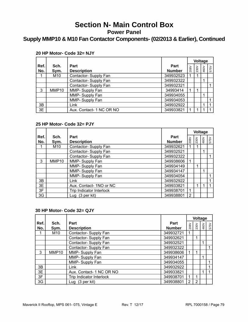
Maverick II Rooftop, MPS 061- 075, Vintage E Rev. T 12/17 RPL 7000158 / Page 79
Voltage Ref. Sch. Part Part No. Sym. Description Number 1 M10 Contactor- Supply Fan 349932621 1 1 Contactor- Supply Fan 349932521 1 Contactor- Supply Fan 349932322 1 3 MMP10 MMP- Supply Fan 349938606 1 MMP- Supply Fan 349934149 1 MMP- Supply Fan 349934147 1 MMP- Supply Fan 349934054 1 3B Link 349932922 1 3E Aux. Contact- 1NO or NC 349933821 1 1 1 3F Trip Indicator Interlock 349938701 1 3G Lug (3 per kit) 349938801 2
208V
230V
460V
575V
25 HP Motor- Code 32= PJY
Voltage Ref. Sch. Part Part No. Sym. Description Number 1 M10 Contactor- Supply Fan 349932721 1 Contactor- Supply Fan 349932621 1 Contactor- Supply Fan 349932521 1 Contactor- Supply Fan 349932322 1 3 MMP10 MMP- Supply Fan 349938606 1 1 MMP- Supply Fan 349934147 1 MMP- Supply Fan 349934055 1 3B Link 349932922 1 3E Aux. Contact- 1 NC OR NO 349933821 1 1 3F Trip Indicator Interlock 349938701 1 1 3G Lug (3 per kit) 349938801 2 2
208V
230V
460V
575V
30 HP Motor- Code 32= QJY
Section N- Main Control BoxPower Panel
Supply MMP10 & M10 Fan Contactor Components- (02/2013 & Earlier), Continued
Voltage Ref. Sch. Part Part No. Sym. Description Number 1 M10 Contactor- Supply Fan 349932523 1 1 Contactor- Supply Fan 349932322 1 Contactor- Supply Fan 349932321 1 3 MMP10 MMP- Supply Fan 34993414 1 1 MMP- Supply Fan 349934055 1 MMP- Supply Fan 349934053 1 3B Link 349932922 1 1 3E Aux. Contact- 1 NC OR NO 349933821 1 1 1 1
208V
230V
460V
575V
20 HP Motor- Code 32= NJY

Maverick II Rooftop, MPS 061- 075, Vintage E Rev. T 12/17 RPL 7000158 / Page 80
Voltage Ref. Sch. Part Part No. Sym. Description Number 1 M10 Contactor- Supply Fan 349932722 1 Contactor- Supply Fan 349932721 1 Contactor- Supply Fan 349932522 1 1 3 MMP10 MMP- Supply Fan 349938607 1 1 MMP- Supply Fan 349934148 1 1 3E Aux. Contact- 1 NC OR NO 349933821 1 1 3F Trip Indicator Interlock 349938701 1 1 3G Lug (3 per kit) 349938801 11 11
208V
230V
460V
575V
40 HP Motor- Code 32= RJY
Voltage Ref. Sch. Part Part No. Sym. Description Number 1 M10 Contactor- Supply Fan 349932702 1 Contactor- Supply Fan 349932722 1 Contactor- Supply Fan 349932621 1 Contactor- Supply Fan 349932523 1 3 MMP10 MMP- Supply Fan 349938607 1 1 MMP- Supply Fan 349934149 1 1 3E Aux. Contact- 1 NC OR NO 349933821 1 1 3F Trip Indicator Interlock 349938701 1 1 3G Lug (3 per kit) 349938801 12 12
208V
230V
460V
575V
50 HP Motor- Code 32= SJY
1 Also requires 3 ring terminals.
2 Also requires 3 ring terminals.
Section N- Main Control BoxPower Panel
Supply MMP10 & M10 Fan Contactor Components- (02/2013 & Earlier), Continued

Maverick II Rooftop, MPS 061- 075, Vintage E Rev. T 12/17 RPL 7000158 / Page 81
062
Ref. Sch. Part Part No. Sym. Description Number Compressor Contactors & Parts 1 M1- 4 Contactor- Compressor 193426823 4 M1- 4 Contactor- Compressor 349932322 4 4
1A Front Mounted Contact- 1NO- 1NC 349931923 4 4 4
Compressor MMP’s & Parts 3 MMP1- 4 Manual Motor Protector- Compr. 349934149 4 Manual Motor Protector- Compr. 349934055 4 Manual Motor Protector- Compr. 349934053 4
3B Link 349932922 4 4
3E Front Mounted Contact- 1NO 349933821 4 4 4
208/
230V
460V
575V
Section N- Main Control BoxPower Panel
Unit Size 062E: Compressor MMP1- 4 and Contactor M1- 4- (02/2013 & Earlier)
MMP3E
Contactor1
3
MMP1- 4 & M1- 4 Contactor Link Detail208/230V
Front Mounted Contact
MMP1- 4 & M1- 4 Contactor Link Detail460/575V
MMP 3
Link 3B
Front Mounted Contact 3E
Front Mount-ed Contact 1A
Contactor 1
Front Mount-ed Contact 1A

Maverick II Rooftop, MPS 061- 075, Vintage E Rev. T 12/17 RPL 7000158 / Page 82
070
Ref. Sch. Part Part No. Sym. Description Number Compressor Contactors & Parts 1 M1- 6 Contactor- Compressor 193426822 6 M1- 6 Contactor- Compressor 349932321 6 6
1A Front Mounted Contact- 1NO- 1NC 349931923 6 6 6
Compressor MMP’s & Parts 3 MMP1- 6 Manual Motor Protector- Compr. 349934148 6 Manual Motor Protector- Compr. 349934053 6 Manual Motor Protector- Compr. 349934052 6
3B Link 349932922 6 6
3E Front Mounted Contact- 1NO 349933821 6 6 6
208/
230V
460V
575V
MMP3E
Contactor1
3
MMP1- 6 & M1- 6 Contactor Link Detail208/230V
Front Mounted Contact
MMP1- 6 & M1- 6 Contactor Link Detail460/575V
MMP 3
Link 3B
Front Mounted Contact 3E
Front Mount-ed Contact 1A
Contactor 1
Front Mount-ed Contact 1A
Section N- Main Control BoxPower Panel
Unit Size 070E: Compressor MMP1- 6 and Contactor M1- 6- (02/2013 & Earlier)

Maverick II Rooftop, MPS 061- 075, Vintage E Rev. T 12/17 RPL 7000158 / Page 83
075
Ref. Sch. Part Part No. Sym. Description Number Compressor Contactors & Parts 1 M1- 6 Contactor- Compressor 193426823 6 M1- 6 Contactor- Compressor 349932321 6 6
1A Front Mounted Contact- 1NO- 1NC 349931923 6 6 6
Compressor MMP’s & Parts 3 MMP1- 6 Manual Motor Protector- Compr. 349934149 6 Manual Motor Protector- Compr. 349934053 6 Manual Motor Protector- Compr. 349934052 6
3B Link 349932922 6 6
3E Front Mounted Contact- 1NO 349933821 6 6 6
208/
230V
460V
575V
MMP3E
Contactor1
3
MMP1- 6 & M1- 6 Contactor Link Detail208/230V
Front Mounted Contact
MMP1- 6 & M1- 6 Contactor Link Detail460/575V
MMP 3
Link 3B
Front Mounted Contact 3E
Front Mount-ed Contact 1A
Contactor 1
Front Mount-ed Contact 1A
Section N- Main Control BoxPower Panel
Unit Size 075E: Compressor MMP1- 6 and Contactor M1- 6- (02/2013 & Earlier)
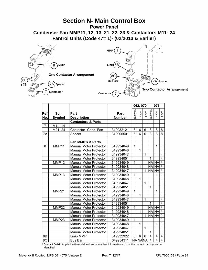
Maverick II Rooftop, MPS 061- 075, Vintage E Rev. T 12/17 RPL 7000158 / Page 84
Section N- Main Control BoxPower Panel
Condenser Fan MMP11, 12, 13, 21, 22, 23 & Contactors M11- 24Fantrol Units (Code 47= 1)- (02/2013 & Earlier)
MMP
Link
Contactor
8B
7
8
062, 070 075 Ref. Sch. Part Part No. Symbol Description Number Contactors & Parts 7 M11- 14 M21- 24 Contactor- Cond. Fan 349932121 6 6 6 8 8 8 7A Spacer 349906501 6 6 6 8 8 8
Fan MMP’s & Parts 8 MMP11 Manual Motor Protector 349934049 1 1 1
Manual Motor Protector 349934048 1 1
Manual Motor Protector 349934047 1 1
Manual Motor Protector 349934051 1 1
MMP12 Manual Motor Protector 349934049 1 NA NA 1
Manual Motor Protector 349934048 1 NA NA 1
Manual Motor Protector 349934047 1 NA NA 1
MMP13 Manual Motor Protector 349934049 1 1 1
Manual Motor Protector 349934048 1 1
Manual Motor Protector 349934047 1 1
Manual Motor Protector 349934051 1 1
MMP21 Manual Motor Protector 349934049 1 1 1
Manual Motor Protector 349934048 1 1
Manual Motor Protector 349934047 1 1
Manual Motor Protector 349934051 1 1
MMP22 Manual Motor Protector 349934049 1 NA NA 1
Manual Motor Protector 349934048 1 NA NA 1
Manual Motor Protector 349934047 1 NA NA 1
MMP23 Manual Motor Protector 349934049 1 1
Manual Motor Protector 349934048 1 1 1
Manual Motor Protector 349934047 1 1
Manual Motor Protector 349934051 1 1
8B Link- MMP 349932922 6 6 6 4 4 4 8C Bus Bar 349934311 NA NA NA 4 4 4
208/
230V
460V
575V
208/
230V
460V
575V
Link 8B
Contactor 7
Bus Bar
8C
8MMP
One Contactor Arrangement
Two Contactor ArrangementSpacer7A
Spacer7A
1 Contact Daikin Applied with model and serial number information so that the correct part(s) can be identified.

Maverick II Rooftop, MPS 061- 075, Vintage E Rev. T 12/17 RPL 7000158 / Page 85
Section N- Main Control BoxPower Panel
Condenser Fan MMP12- 24, Contactors M11- 24, Fuses F11, F21Speedtrol Units (Code 47= 2)- (02/2013 & Earlier)
MMP & Contactors Detail
One Contactor Arrangement Two Contactor Arrangement
062, 070 075 Ref. Sch. Part Part No. Symbol Description Number Speedtrol Fusing 1 F11, 21 Fuse Block 023780232 2 2 2 2 2 2 2 2 2 Fuse Cover/Puller 349938227 3 3 3 3 3 3 3 3 3 F11, 21 Fuse- Speedtrol 349937127 6 6 Fuse- Speedtrol 349937126 6 6 Fuse- Speedtrol 049759820 6 6 Fuse- Speedtrol 1 6 6 4 Dinrail Adapter 349938412 2 2 2 2 2 2 2 2
Cond. Fan Contactors 7 M12- 24 Contactor- Cond. Fan 349932121 4 4 4 4 6 6 6 6 7A Spacer 349906501 4 4 4 4 6 6 6 6
Fan MMP’s & Parts 8 MMP12 Manual Motor Protector 349934049 1 1 1 1 1 1
Manual Motor Protector 349934048 1 1 1 1 1
MMP13 Manual Motor Protector 349934049 1 1 1 1 1 1
Manual Motor Protector 349934048 1 1 1 1
Manual Motor Protector 349934051 1 1 1 1
MMP22 Manual Motor Protector 349934049 1 1 1 1 1 1
Manual Motor Protector 349934048 1 1 1 1
MMP23 Manual Motor Protector 349934049 1 1 1 1 1 1
Manual Motor Protector 349934048 1 1 1 1
Manual Motor Protector 349934051 1 1 1 1
8B Link- MMP 349932922 4 4 4 4 4 4 4 1
8C Bus Bar 349934311 NA NA NA NA 2 2 2 1
208V
230V
460V
575V
208V
230V
460V
575V
Speedtrol Fuses
Fuse BlockFuse
Puller
2
3 1
F11 OR F21
4Adapter
MMP
Link
Contactor
8B
7
8
Spacer7A
Link 8B
Contactor 7
Bus Bar
8C
8MMP
Spacer7A
1 Contact Daikin Applied with model and serial number information so that the correct part(s) can be identified.
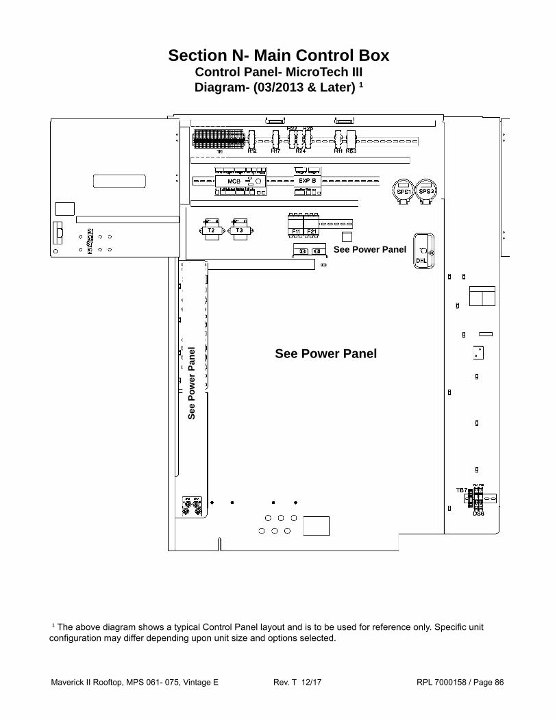
Maverick II Rooftop, MPS 061- 075, Vintage E Rev. T 12/17 RPL 7000158 / Page 86
Section N- Main Control BoxControl Panel- MicroTech IIIDiagram- (03/2013 & Later) 1
See Power Panel
1 The above diagram shows a typical Control Panel layout and is to be used for reference only. Specific unit configuration may differ depending upon unit size and options selected.
See Power Panel
See
Pow
er P
anel
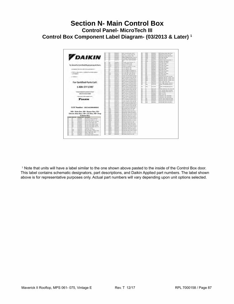
Maverick II Rooftop, MPS 061- 075, Vintage E Rev. T 12/17 RPL 7000158 / Page 87
Section N- Main Control BoxControl Panel- MicroTech III
Control Box Component Label Diagram- (03/2013 & Later) 1
1 Note that units will have a label similar to the one shown above pasted to the inside of the Control Box door. This label contains schematic designators, part descriptions, and Daikin Applied part numbers. The label shown above is for representative purposes only. Actual part numbers will vary depending upon unit options selected.
GOI Number: H023442000400R01
MB= Main Box; BB= Bypass Box; EB= Electric Heat Box; GB= Gas Box; PB= Prop
Exhaust Box; Location Device ID McQuay Part # Description GB AS 033003800 Ctrl-press air switch gas burner
GB AS 067297701 Conduit fitting nipple 1-2 3-4
GB FLC 193423703 Control Temp Fan Limit Gas Heat
GB FSG 073300702 Ctrl-temp flame safegrd base
GB FSG 073300803 Ctrl-temp Flame Safegrd Control
GB FSG 073300901 Ctrl-temp flame safegrd amplifier
GB FSG 073301002 Ctrl-temp flame safegrd timer 90
GB IT 034482600 Transformer Ignition
GB R20A 349934764 DPDT Relay 15A 120VAC
GB R20A 349964702 Mounting Adapter 2P Relay to Dinra
GB S3 033536700 Switch Toggle 4PST 125V
MB DHL 065493801 Pressure Switch SPDT
MB DS1 193585102 Circuit Breaker Molded Case Switch
MB DS1 193556201 lug kit, 3 pcs with power control t
MB DS1 193404101 Connector 1-4 quick connect tab
MB DS1 193553301 lug kit, 3 pcs, T3 Frame, 225A
MB DS1 349939015 SCREW, PANHEAD AB-type, #8-18 X 3"
MB DS1 193550801 Circuit Breaker Operating Mechanism
MB DS1 193422102 HANDLE, PISTOL, ABB DISCONNECT, RED
MB DS6 193443801 Fuse holder, Circuit Protector, 2 P
MB DS6 349937131 Fuse 10A Rejection Type
MB EXP-B 193407501 Extension I-O 2 15 Points
MB EXP-B 193409701 Connector for extension I-O - Direc
MB F1A 349937129 Fuse 8A Rejection Type
MB F1B 349937129 Fuse 8A Rejection Type
MB F1C 349937035 Fuse 15A Midget Non-Rejection Ty
MB F3 349937035 Fuse 15A Midget Non-Rejection Ty
MB FB10 193403117 Fuse 100A 600V Class J Fast Acti
MB FB20 193403109 Fuse 35A 600V Class J Fast Actin
MB M1 193591601 Contactor IEC 40A 120VAC Coil Screw
MB M1 193542701 Contactor Auxiliary Contact 2NO 2NC
MB M1 193547401 MMP to Contactor Link Module Size S
MB M11 193534105 Contactor IEC 7A 120VAC Coil Spring
MB M11 193545901 MMP to Contactor Link Module Screw
MB M12 193534105 Contactor IEC 7A 120VAC Coil Spring
MB M12 193545901 MMP to Contactor Link Module Screw
MB M13 193534105 Contactor IEC 7A 120VAC Coil Spring
MB M13 193545901 MMP to Contactor Link Module Screw
MB M2 193591601 Contactor IEC 40A 120VAC Coil Screw
MB M2 193542701 Contactor Auxiliary Contact 2NO 2NC
MB M2 193547401 MMP to Contactor Link Module Size S
MB M21 193534105 Contactor IEC 7A 120VAC Coil Spring
MB M21 193545901 MMP to Contactor Link Module Screw
MB M22 193534105 Contactor IEC 7A 120VAC Coil Spring
MB M22 193545901 MMP to Contactor Link Module Screw
MB M23 193534105 Contactor IEC 7A 120VAC Coil Spring
MB M23 193545901 MMP to Contactor Link Module Screw
MB M3 193591601 Contactor IEC 40A 120VAC Coil Screw
MB M3 193542701 Contactor Auxiliary Contact 2NO 2NC
MB M3 193547401 MMP to Contactor Link Module Size S
MB M4 193591601 Contactor IEC 40A 120VAC Coil Screw
MB M4 193542701 Contactor Auxiliary Contact 2NO 2NC
MB M4 193547401 MMP to Contactor Link Module Size S
MB MCB 193407301 Base Controller with IP and Inbuilt
MB MMP1 193543304 MMP Class 10 Size S2 22 to 32A
MB MMP1 193546201 MMP Auxiliary Contact Sizes S2 and
MB MMP1 193546601 MMP Bus Bar 2 Position No Lateral A
MB MMP1 193547201 MMP Bus Bar Type E Feeder Terminal
MB MMP11 193542908 MMP Class 10 Size S00 2.2 to 3.2A S
MB MMP11 193544401 MMP Bus Bar 3 Position No Lateral A
MB MMP11 193545101 MMP Bus Bar Type E Feeder Terminal
MB MMP12 193542908 MMP Class 10 Size S00 2.2 to 3.2A S
MB MMP13 193542908 MMP Class 10 Size S00 2.2 to 3.2A S
MB MMP2 193543304 MMP Class 10 Size S2 22 to 32A
MB MMP2 193546201 MMP Auxiliary Contact Sizes S2 and
MB MMP2 193546601 MMP Bus Bar 2 Position No Lateral A
MB MMP2 193547201 MMP Bus Bar Type E Feeder Terminal
MB MMP21 193542908 MMP Class 10 Size S00 2.2 to 3.2A S
MB MMP21 193544401 MMP Bus Bar 3 Position No Lateral A
MB MMP21 193545101 MMP Bus Bar Type E Feeder Terminal
MB MMP22 193542908 MMP Class 10 Size S00 2.2 to 3.2A S
MB MMP23 193542908 MMP Class 10 Size S00 2.2 to 3.2A S
MB MMP3 193543304 MMP Class 10 Size S2 22 to 32A
MB MMP3 193546201 MMP Auxiliary Contact Sizes S2 and
MB MMP4 193543304 MMP Class 10 Size S2 22 to 32A
MB MMP4 193546201 MMP Auxiliary Contact Sizes S2 and
MB OAER 349934722 DPDT Relay 10A 24VAC
MB OAER 349934822 Relay Socket DPDT
MB PB11 030372777 Distribution Power Terminal Brd 17
MB PVM1 112022001 3PH Monitor 190-480VAC
MB R12 349934724 DPDT Relay 10A 120VAC
MB R12 349934822 Relay Socket DPDT
MB R22 349934724 DPDT Relay 10A 120VAC
MB R22 349934822 Relay Socket DPDT
MB R24 349934724 DPDT Relay 10A 120VAC
MB R24 349934822 Relay Socket DPDT
MB R25 349934724 DPDT Relay 10A 120VAC
MB R25 349934822 Relay Socket DPDT
MB R63 349934923 3PDT Relay 10A 120VAC
MB R63 349935021 Relay Socket 3PDT
MB REC1 039003600 Receptacle Ground Fault Interrupter
MB RES1 044690151 RESISTOR 1500 Ohm 1-8 Watt 1% Pr
MB RES2 044690110 RESISTOR 1000 Ohm 1-8 Watt 1% Pr
MB RES4 044690151 RESISTOR 1500 Ohm 1-8 Watt 1% Pr
MB S1 018446400 Switch Toggle DPST 125V
MB S7 193412101 Switch Toggle 2position ON-ON S
MB SPS1 910117462 SENSOR, AIR PRESSURE/VELOCITY, DIN
MB SPS2 910117463 SENSOR, AIR PRESSURE/VELOCITY, DIN
MB T1 099477106 MICRON Transformer, CPT, W/ FB, 150
MB T1 099477601 Cover, Terminals, Micron 6-terminal
MB T1 099477401 Cover, Fuseholder, Micron Type 2 Tr
MB T1 040500320 Washer, 1/4" Flat
MB T1 193444904 Washer, Split Lock
MB T2 349937303 Transformers 75va 120V-24Vac
MB T3 349937303 Transformers 75va 120V-24Vac
PB M51 193534106 Contactor IEC 9A 120VAC Coil Spring
PB M52 193534106 Contactor IEC 9A 120VAC Coil Spring
PB OL51 193547910 Overload Relay Class 10 Size S00 5.
PB OL52 193547910 Overload Relay Class 10 Size S00 5.

Maverick II Rooftop, MPS 061- 075, Vintage E Rev. T 12/17 RPL 7000158 / Page 88
Sch. Part Part Qty. Sym. Description Number Main Controller MCB Main Controller- Must be programmed (unit GO# required) 193407301 1 Connector, Extension I/O Direct Connect 193409701 2
Terminal Block, MCB- 2 Pole 193410302 1 Terminal Block, MCB- 3 Pole 193410303 6 Terminal Block, MCB- 5 Pole 193410305 1 Terminal Block, MCB- 6 Pole 193410306 1 Terminal Block, MCB- 7 Pole 193410307 1 - MicroTech III Remote Unit Keypad 1 193408003 1 - Remote Interface Display 1 193408001 1 Terminal Block, MCB- 8 Pole 193410308 2 Expansion Module EXP B Expansion Module- Heat 193407501 1 EXP D Expansion Module- Specials 1 193407501 1 Terminal Block, EXP- 2 Pole 193410302 1/board
Terminal Block, EXP- 3 Pole 193410303 1/board
Terminal Block, EXP- 7 Pole 193410307 1/board
Terminal Block, EXP- 8 Pole 193410308 2/board
Communication Card 1
COM Bacnet- MSTP Code 12= BE, BF, BW 090016710 1 Bacnet- IP Code 12= EE, EF, EW 090016709 1 LonWorks- Discharge Code 12= LE, LW 090016712 1 LonWorks- Constant Volume Code 12= LF 090016711 1 Phase Voltage Monitor (PVM) 1 Code 17= CP, YP) PVM1 Phase Voltage Monitor, 208- 460V 12/16 & Earlier 112022001 1 Phase Voltage Monitor, 575V 12/16 & Earlier 112022002 1 Phase Voltage Monitor, 208- 460V 2/17 & Later 193599301 1 Phase Voltage Monitor, 575V 2/17 & Later 193599303 1 - Socket, PVM 2/17 & Later 193599401 1 Resistors 1
RES1 Resistor- Refrigeration Circuit #1 1500 OHM 044690151 1 RES2 Resistor- Refrigeration Circuit #2 1000 OHM 044690110 1 RES3 Resistor- Freezestat (FS1) 1000 OHM 044690110 1 RES4 Resistor- OAE 1500 OHM 044690151 1 RES6,7,8 Resistor- SPS1, SPS2, SPS3 500 OHM 044690146 1/switch
Switches- Control HS1 Switch- Electric Heat Shutdown Code 04= E 001355000 1 S1 Switch- System On/Off Gas Heat Units DPST/15A 018446400 1 Electric, HW or No Heat SPST/20A 001355000 1 S4 Switch- Inverter Bypass On/Off DPST/15A 018446400 1 S7 Switch- Local On/Auto/Off to Controller SPDT/15A 193412101 1 Duct Hi Limit and Duct Static Pressure Sensors DHL Duct Hi Limit Switch 065493801 1 SPS1 Pressure Transducer- Duct Sensor Code 13= 1, 2, 3 910117462 1 SPS2 Pressure Transducer- Duct Sensor Code 13= 2 910117462 1 Pressure Transducer- Space Sensor Code 13= 3, 4 910117463 11 Not Shown on diagram.2 Quantity varies depending upon unit options selected.3 For units built 1/17 contact Daikin Applied to ensure that the correct part(s) are identified.
Section N- Main Control BoxControl Panel- MicroTech III
Components- (03/2013 & Later)

Maverick II Rooftop, MPS 061- 075, Vintage E Rev. T 12/17 RPL 7000158 / Page 89
Sch. Part Part Qty. Sym. Description Number Relays R11 Relay- Speedtrol inverter AFD11 349934724 1 R12 Relay- Condenser Fan 349934724 1 R13 Relay- Condenser Fan 3 349934724 1 R14 Relay- Condenser Fan 3 349934724 1 R20 Relay- Heat 3 349934724 1 R22 Relay- Gas Heat 349934724 1 R24 Relay- Gas Heat Alarm 349934724 1 R25 Relay- Gas Heat, Start Supply Fan Inverter Code 14= 6 349934724 1 R63 Relay- Duct Hi Limit Units with Return Fan Inverter 3PDT/120V 349934923 1 Units with No Return Fan Inverter DPDT/120V 349934724 1 R81 Relay- Inverter Reset 3 4P/6A/24V 349934722 1 R82 Relay- Inverter Reset 3 4P/6A/24V 349934722 1 R83 Relay- Smoke 3 4P/6A/24V 193413601 1 R84 Relay- Smoke 3 4P/6A/24V 193413601 1 R85 Relay- Smoke 3 4P/6A/24V 193413601 1 R86 Relay- Smoke 3 4P/6A/24V 193413601 1 R87 Relay- Smoke 3 4P/6A/24V 193413601 1 R88 Relay- Smoke 3 4P/6A/24V 193413601 1 Transformers T2 Transformer- Control 120- 24V 349937303 1 T3 Transformer- Control 120- 24V 349937303 1 Time Delays TD20 Time Delay, Return Air Fan 3 028210106 1 Terminal Block TB1 Terminal Block 349930641 1
Sensors ZNT1 Sensor, Digital- Zone Temperature w/ Tenant O/R & Setpoint Adj. 4 910143408 1 Sensor- Zone Temperature w/ Tenant Override 4 113117701 1 Sensor- Zone Temp. w/ Tenant Override & Remote Setpoint Adj. 2, 4 113117801 1 DAT Sensor- Discharge Air Temperature 3 193414602 1 EFT Sensor- Entering Air Temperature 3 193414602 1 OAT Sensor- Outside Air Temperature 3 193414602 1 RAT Sensor- Return Air Temperature 3 193414602 1 EAT Sensor- Exhaust Air Temperature 3 193414602 1 LAT Sensor- Leaving Air Temperature 3 193414602 1
Section N- Main Control BoxControl Panel- MicroTech III
Components- (03/2013 & Later), Continued
10
50
1456
22
68
30
86
2680
°F
°C
62 7418
ZNT1 Sensor910143408
ZNT1 Sensor113117701
ZNT1 Sensor113117801
1 Varies depending on unit options. Part number is for one individual section. Ground Block is p/n 349930647.2 SCC Units only (Code 12= *F, *W).3 Not Shown on diagram.4 In late 2013, Digital Room Sensor p/n 910143408 was added as the preferred option. The other Zone Temperature Sensors
are available as options. For positive p/n identification, refer to the drawings below.

Maverick II Rooftop, MPS 061- 075, Vintage E Rev. T 12/17 RPL 7000158 / Page 90
Section N- Main Control BoxPower Panel
Diagrams- (03/2013 & Later) 1
See Control Panel
1 The above diagram shows a typical Power Panel layout and is to be used for reference only. Specific unit configuration may differ depending upon unit size and options selected.
PL1
- PL4
3 Pl
ugs
See
Con
trol
Pan
el

Maverick II Rooftop, MPS 061- 075, Vintage E Rev. T 12/17 RPL 7000158 / Page 91
Sch. Part Part Voltage Sym. Description Number 208V 230V 460V 575V Terminal Blocks TB2,3,4,7 Terminal Block 349930641 1 1 1 1
Transformer- Main 2
T1 Transformer- Main Control Electric, Hydronic, No Heat Code 04= E,W,Y 099477205 1 Electric, Hydronic, No Heat Code 04= E,W,Y 099477105 1 1 Electric, Hydronic, No Heat Code 04= E,W,Y 099477305 1 Gas Heat Code 04= A 099477206 1 Gas Heat Code 04= A 099477106 1 1 Gas Heat Code 04= A 099477306 1 Fuses- T1 F1A, B Fuse- T1 Transformer, Primary Electric, Hydronic, No Heat Code 04= E,S,W,Y 349937132 2 Electric, Hydronic, No Heat Code 04= E,S,W,Y 349937131 2 Electric, Hydronic, No Heat Code 04= E,S,W,Y 349937124 2 Electric, Hydronic, No Heat Code 04= E,S,W,Y 349937129 2 Gas Heat Code 04= A 349937134 2 Gas Heat Code 04= A 349937133 2 Gas Heat Code 04= A 349937129 2 Gas Heat Code 04= A 349937125 2 F1C Fuse- T1 Transformer Gas Heat Code 04= A 349937035 1 1 1 1 Electric, Hydronic, No Heat Code 04= E,S,W,Y 349937033 1 1 1 1 Misc. Fuses / Circuit Breakers F2,F3 Fuses- Control Circuit / Burner Motor Fuse Block 023780223 1/fuse 1/fuse 1/fuse 1/fuse Fuse Cover 349938227 1/fuse 1/fuse 1/fuse 1/fuse F2 Fuse- 2000+VA transformer 349937035 1 1 1 1 F3 Fuse- Blower Motor Code 04= A 349937035 1 1 1 1 CB10 Circuit Breaker- Exhaust Fan (one motor) Code 24= 1 193550201 1 Circuit Breaker- Exhaust Fan (two motors) Code 24= 2 193550202 1 F10 Fuse- Exhaust Fan Fuse Block (one motor) Code 20=HE & Code 24= 1 023780232 1 1 1 Fuse Cover (one motor) Code 20=HE & Code 24= 1 349938227 1/fuse 1/fuse 1/fuse Fuse (one motor) Code 20=HE & Code 24= 1 349937136 3 Fuse (one motor) Code 20=HE & Code 24= 1 349937135 3 Fuse (one motor) Code 20=HE & Code 24= 1 349937133 3 Fuse Block (two motors) Code 20=HE & Code 24= 2 193428502 1 1 Fuse Cover (two motors) Code 20=HE & Code 24= 2 193428602 1/fuse 1/fuse 1/fuse Fuse Block (two motors) Code 20=HE & Code 24= 2 023780232 1 Fuse Cover (two motors) Code 20=HE & Code 24= 2 349938227 1/fuse Fuse (two motors) Code 20=HE & Code 24= 2 113085250 3 3 Fuse (two motors) Code 20=HE & Code 24= 2 349937135 3 PL1- 43 Plugs 3 4 4 Pin Plug 349930201 varies varies varies varies 5 6 Pin Plug 349930403 varies varies varies varies 6 12 Pin Plug 349930405 varies varies varies varies 7 3 Pin Cap Kit 349930501 varies varies varies varies 8 6 Pin Cap Kit 349930503 varies varies varies varies 9 9 Pin Cap Kit 349930504 varies varies varies varies 10 15 Pin Cap Kit 349930506 varies varies varies varies
Section N- Main Control BoxPower Panel
Terminal Blocks, T1 Transformer & Fusing, Fuses, Plugs- (03/2013 & Later)
1 Varies depending on unit options. Part number is for one individual section. Ground block is p/n 349930647. When required TB2, 3, 4 or 7 use Jumpers p/n 349930922 (2 pole), 349930923 (3 pole), 349930924 (4 pole), 349930925 (5 pole).
2 All T1 Transformers use Fuse Holder p/n 099477402 & Terminal Cover p/n 099477602.3 All possible Plugs used are listed. Check actual unit to verify which Plug is required.4 Used for PL1, PL, 2, PL3, PL4, PL5, PL6, PL22,PL23, PL24, PL37, PL38.5 Used with Strain Relief (p/n 300041173) & 6 pin Cap Kit (p/n 349930503). Used for PL20, PL21.6 Used for PL11, PL12, PL25, PL26, PL27, PL28, PL29, PL30 (PL11 & 12 also use Strain Relief p/n 300041175 & Cap Kit p/n 349930505).7 Used for PL16, PL17, PL31, PL32, PL33, PL34, PL39, PL40, PL41, PL42. 8 Used for PL9, PL10. 9 Used for PL18, PL19, PL35, PL36, PL43. 10 Used for PL7, PL8.
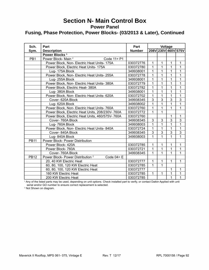
Maverick II Rooftop, MPS 061- 075, Vintage E Rev. T 12/17 RPL 7000158 / Page 92
Sch. Part Part Voltage Sym. Description Number 208V 230V 460V 575V Power Blocks 1
PB1 Power Block- Main 2 Code 11= P1 Power Block, Non- Electric Heat Units- 175A 030372776 1 1 1 1 Power Block, Electric Heat Units- 175A 030372780 1 1 1 1 Lug- 175A Block 349938001 1 1 1 1 Power Block, Non- Electric Heat Units- 255A 030372778 1 1 1 1 Lug- 255A Block 349938001 1 1 1 1 Power Block, Non- Electric Heat Units- 380A 030372779 1 1 1 1 Power Block, Electric Heat- 380A 030372782 1 1 1 1 Lug- 380A Block 349938001 1 1 1 1 Power Block, Non- Electric Heat Units- 620A 030372702 1 1 1 1 Cover- 620A Block 349938345 3 3 3 3 Lug- 620A Block 349938002 1 1 1 1 Power Block, Non- Electric Heat Units- 760A 030372760 1 1 1 1 Power Block, Electric Heat Units, 208/230V- 760A 030372772 1 1 Power Block, Electric Heat Units, 460/575V- 760A 030372760 1 1 Cover- 760A Block 349938345 3 3 3 3 Lug- 760A Block 349938003 1 1 1 1 Power Block, Non- Electric Heat Units- 840A 030372724 1 1 1 1 Cover- 840A Block 349938345 3 3 3 3 Lug- 840A Block 349938003 1 1 1 1 PB11 Power Block- Power Distribution Power Block- 420A 030372785 1 1 1 1 Power Block- 760A 030372721 1 1 1 1 Cover- 760A Block 349938345 1 1 1 1 PB12 Power Block- Power Distribution 2 Code 04= E 20, 40 KW Electric Heat 030372777 1 1 1 1 60, 80, 100, 120 KW Electric Heat 030372785 1 1 60, 80, 100, 120 KW Electric Heat 030372777 1 1 160 KW Electric Heat 030372785 1 1 1 1 200 KW Electric Heat 030372785 1 11 Any of the listed parts may be used, depending on unit options. Check installed part to verify, or contact Daikin Applied with unit
serial and/or GO number to ensure correct replacement is selected. 2 Not Shown on diagram.
Section N- Main Control BoxPower Panel
Fusing, Phase Protection, Power Blocks- (03/2013 & Later), Continued

Maverick II Rooftop, MPS 061- 075, Vintage E Rev. T 12/17 RPL 7000158 / Page 93
Sch. Part Part Voltage Sym. Description Number 208V 230V 460V 575V Receptacle REC1 Receptacle 5 039003600 1 1 1 1 Disconnect Switch 1
DS1 Disconnect Switch- Main Switch- 100A 193444703 1 1 1 1 Handle 193422102 1 1 1 1 Shaft 2 193596420 1 1 1 1 Switch- 150A 193585101 1 1 1 1 Handle 193422102 1 1 1 1 Mechanism 193550801 1 1 1 1 Shaft 2 193596420 1 1 1 1 Lugs 4 193553301 1 1 1 1 Switch- 250A 193551601 1 1 1 1 Handle 193595701 1 1 1 1 Mechanism 193551001 1 1 1 1 Shaft 3 300049193 1 1 1 1 Lugs 4 193553801 1 1 1 1 Switch- 400A 193551701 1 1 1 1 Handle 193595701 1 1 1 1 Mechanism 193551001 1 1 1 1 Shaft 3 300049193 1 1 1 1 Lugs 4 193554001 1 1 1 1 Switch- 600A 193551801 1 1 1 1 Handle 193595701 1 1 1 1 Mechanism 193551001 1 1 1 1 Shaft 3 300049193 1 1 1 1 Lugs 4 193554101 2 2 2 2 Switch- 800A 193551901 1 1 1 1 Handle 193595701 1 1 1 1 Mechanism 193558201 1 1 1 1 Shaft 3 300049193 1 1 1 1 Lugs 4 193557001 2 2 2 2 Switch- 1000A 193552001 1 1 1 1 Handle 193588001 1 1 1 1 Mechanism 193550801 1 1 1 1 Shaft 3 300049193 1 1 1 1 Lugs 4 193555801 2 2 2 2
Section N- Main Control BoxPower Panel
Receptacle, Disconnect Switch- (03/2013 & Later), Continued
1 Disconnects are sized according to various unit specifications. Check installed switch to verify the correct DS1 size, or contact Daikin Applied with model and serial number information so that the required part(s) can be identified.
2 This Shaft is 14.25” OAL and is designed to be cut to length in the field.3 This Shaft is 7.21” (183mm) OAL and is designed to be cut to length in the field. For a 19.69” (500mm) OAL use p/n 300040299.4 Three Lugs are included with each p/n.5 Not Shown on diagram.

Maverick II Rooftop, MPS 061- 075, Vintage E Rev. T 12/17 RPL 7000158 / Page 94
Section N- Main Control BoxPower Panel
Supply MMP10 & M10 Fan Contactor Detail Diagrams- (03/2013 & Later)
MMP
3
Link 3B
Contactor
1
Front Mtd.Contact
2
MMP10 & M10 Link Detail3, 5 HP Motors- 460/575V
7.5 HP Motors- 575V
NOTE: The diagrams show ALL possible parts. Not every part shown applies to every unit size/voltage combination.
MMP10 & M10 Link Detail3, 5 HP Motors- 208/230V
7.5 HP Motors- 208/230/460V10 HP Motors- All Voltages
15, 20 HP Motors- 460V
MMP10 & M10 Link Detail20, 25, 30 HP Motors- 208/230V
40 HP Motors- 460V50 HP Motors- 460/575V
MMP
3
4A4
Contactor
1
MMP
2
Contactor1
3MMP 3
Contactor1
MMP10 & M10 Link Detail15 HP Motors- 208/230/575V
20, 40 HP Motors- 575V25, 30 HP Motor- 460/575V
3EPhase Barrier
Spacer3A
3EPhase Barrier
Front Mtd.Contact
Link 3B
2Front Mtd.
Contact Link3B
Front Mtd.Contact
2
Contactor
1
Link 3B
3EPhase Barrier
Overload
TerminalBlock
MMP10 & M10 Link Detail40, 50 HP Motors- 208/230V
3Circuit Breaker
(not shown)

Maverick II Rooftop, MPS 061- 075, Vintage E Rev. T 12/17 RPL 7000158 / Page 95
Section N- Main Control BoxPower Panel
Supply Fan Components- (03/2013 & Later)
3 HP Motor- Code 32= HJY Voltage Ref. Sch. Part Part No. Sym. Description Number 1 M10 Contactor- Supply Fan 12A 193592005 1 1 Contactor- Supply Fan 7A 193534105 1 1 2 Aux. Contact- 1 NC OR NO 193543801 1 1 1 1 3 MMP10 MMP- Supply Fan 7- 10A 193543007 1 1 MMP- Supply Fan 3.5- 5A 193542910 1 1 3A Spacer 193545801 1 1 3B Link 193546001 1 1 Link 193545901 1 1 3E Phase Barrier 193545501 1 1 1 1 N/S CB10 Circuit Breaker- Supply Fan 15A 193550201 1 FB10 Fuseblock- Supply Fan 023780232 1 1 1 Fuse- Supply Fan 15A 349937133 3 Fuse- Supply Fan 10A 349937131 3 Fuse- Supply Fan 7A 349937127 3 Fuse Cover/Puller- Supply Fan 349938227 2 2 2
208V
230V
460V
575V
N/S= Not Shown on Diagram. 2 1 pc. PER Fuse.

Maverick II Rooftop, MPS 061- 075, Vintage E Rev. T 12/17 RPL 7000158 / Page 96
Section N- Main Control BoxPower Panel
Supply Fan Components- (03/2013 & Later), Continued
7.5 HP Motor- Code 32= KJY
5 HP Motor- Code 22 OR 32= JJY Voltage Ref. Sch. Part Part No. Sym. Description Number 1 M10 Contactor- Supply OR Exhaust Fan 25A 193537304 1 Contactor- Supply OR Exhaust Fan 16A 193592006 1 Contactor- Supply OR Exhaust Fan 9A 193534106 1 Contactor- Supply OR Exhaust Fan 7A 193534105 1 2 Aux. Contact- 1 NC OR NO 193543801 1 1 1 1 3 MMP10 MMP- Supply OR Exhaust Fan 11- 16A 193543009 1 1 MMP- Supply OR Exhaust Fan 5.5- 8A 193542912 1 1 3A Spacer 193545801 1 1 3B Link 193546001 1 1 Link 193545901 1 1 3E Phase Barrier 193545501 1 1 1 1 N/S CB10 Circuit Breaker- Supply OR Exhaust Fan 15A 193550201 1 FB10 Fuseblock- Supply OR Exhaust Fan 023780232 1 1 1 Fuse- Supply OR Exhaust Fan 25A 349937136 3 Fuse- Supply OR Exhaust Fan 20A 349937135 3 Fuse- Supply OR Exhaust Fan 10A 349937131 3 Fuse Cover/Puller- Supply OR Exhaust Fan 349938227 1 1 1
208V
230V
460V
575V
N/S= Not Shown on Diagram. 1 1 pc. PER Fuse.
Voltage Ref. Sch. Part Part No. Sym. Description Number 1 M10 Contactor- Supply Fan 25A 193537304 1 1 Contactor- Supply Fan 12A 193592005 1 Contactor- Supply Fan 9A 193534106 1 2 Aux. Contact- 1 NC OR NO 193543801 1 1 1 1 3 MMP10 MMP- Supply Fan 20- 25A 193543012 1 MMP- Supply Fan 17- 22A 193543011 1 MMP- Supply Fan 9- 12.5A 193543008 1 MMP- Supply Fan 7- 10A 193542913 1 3A Spacer 193545801 1 1 1 3B Link 193546001 1 1 1 Link 193545901 1 3E Phase Barrier 193545501 1 1 1 1 N/S CB10 Circuit Breaker- Supply Fan 15A 193550201 1 FB10 Fuseblock- Supply Fan 193428502 1 1 Fuseblock- Supply Fan 023780232 1 Fuse- Supply Fan 35A 113085249 3 3 Fuse- Supply Fan 15A 349937133 3 Fuse Cover- Supply Fan 193428602 1 1 Fuse Cover/Puller- Supply Fan 349938227 2
208V
230V
460V
575V
N/S= Not Shown on Diagram. 2 1 pc. PER Fuse.

Maverick II Rooftop, MPS 061- 075, Vintage E Rev. T 12/17 RPL 7000158 / Page 97
Section N- Main Control BoxPower Panel
Supply Fan Components- (03/2013 & Later), Continued
10 HP Motor- Code 32= LJY Voltage Ref. Sch. Part Part No. Sym. Description Number 1 M10 Contactor- Supply Fan 32A 193537305 1 1 Contactor- Supply Fan 16A 193592006 1 Contactor- Supply Fan 12A 193592005 1 2 Aux. Contact- 1 NC OR NO 193543801 1 1 1 1 3 MMP10 MMP- Supply Fan 27- 32A 193543014 1 MMP- Supply Fan 23- 28A 193543013 1 MMP- Supply Fan 11- 16A 193543009 1 MMP- Supply Fan 9- 12.5A 193543008 1 3A Spacer 193545801 1 1 1 1 3B Link 193546001 1 1 1 1 3E Phase Barrier 193545501 1 1 1 1 N/S CB10 Circuit Breaker- Supply Fan 15A 193550201 1 FB10 Fuseblock- Supply Fan 193428502 1 1 Fuseblock- Supply Fan 023780232 1 Fuse- Supply Fan 50A 113085252 3 Fuse- Supply Fan 45A 113085251 3 Fuse- Supply Fan 20A 349937135 3 Fuse Cover- Supply Fan 193428602 1 1 Fuse Cover/Puller- Supply Fan 349938227 2
208V
230V
460V
575V
N/S= Not Shown on Diagram. 1 1 pc. PER Fuse

Maverick II Rooftop, MPS 061- 075, Vintage E Rev. T 12/17 RPL 7000158 / Page 98
Section N- Main Control BoxPower Panel
Supply Fan Components- (03/2013 & Later), Continued
Voltage Ref. Sch. Part Part No. Sym. Description Number 1 M10 Contactor- Supply Fan 50A 193591602 1 1 Contactor- Supply Fan 25A 193537304 1 Contactor- Supply Fan 25A 193598101 1 2 Aux. Contact- 1 NC OR NO 193546201 1 1 1 Aux. Contact- 1 NC OR NO 193543801 1 3 MMP10 MMP- Supply Fan 36- 45A 193543306 1 MMP- Supply Fan 28- 40A 193543305 1 MMP- Supply Fan 14- 20A 193543010 1 MMP- Supply Fan 11- 16A 193543301 1 3A Spacer 193545801 1 3B Link 193547401 1 1 1 Link 193546001 1 3E Phase Barrier 193545501 1 N/S CB10 Circuit Breaker- Supply Fan 20A 193550202 1 FB10 Fuseblock- Supply Fan 349964253 1 Fuseblock- Supply Fan 193428502 1 Fuseblock- Supply Fan 023780232 1 Fuse- Supply Fan 70A 113085254 3 Fuse- Supply Fan 60A 113085253 3 Fuse- Supply Fan 30A 349937137 3 Fuse Cover- Supply Fan 349964263 1 Fuse Cover- Supply Fan 193428602 1 Fuse Cover/Puller- Supply Fan 349938227 1
208V
230V
460V
575V
N/S= Not Shown on Diagram. 1 1 pc. PER Fuse
15 HP Motor- Code 32= MJY

Maverick II Rooftop, MPS 061- 075, Vintage E Rev. T 12/17 RPL 7000158 / Page 99
Section N- Main Control BoxPower Panel
Supply Fan Components- (03/2013 & Later), Continued
Voltage Ref. Sch. Part Part No. Sym. Description Number 1 M10 Contactor- Supply Fan 65A 193591701 1 1 Contactor- Supply Fan 32A 193537305 1 Contactor- Supply Fan 25A 193598101 1 2 Aux. Contact- 1 NC OR NO 193546201 1 1 1 Aux. Contact- 1 NC OR NO 193543801 1 3 MMP10 MMP- Supply Fan 45- 63A 193543403 1 1 MMP- Supply Fan 23- 28A 193543013 1 MMP- Supply Fan 18- 25A 193543303 1 3A Spacer 193545801 1 3B Link 193547501 1 1 Link 193546001 1 Link 193547401 1 3E Phase Barrier 193547301 1 1 Phase Barrier 193545501 1 N/S CB10 Circuit Breaker- Supply Fan 70A 193550207 1 Circuit Breaker- Supply Fan 60A 193550206 1 Circuit Breaker- Supply Fan 30A 193550203 1 FB10 Fuseblock- Supply Fan 193428502 1 Fuse- Supply Fan 40A 113085250 3 Fuse Cover- Supply Fan 193428602 1
208V
230V
460V
575V
N/S= Not Shown on Diagram.
20 HP Motor- Code 32= NJY
25 HP Motor- Code 32= PJY Voltage Ref. Sch. Part Part No. Sym. Description Number 1 M10 Contactor- Supply Fan 80A 193591702 1 1 Contactor- Supply Fan 40A 193591601 1 Contactor- Supply Fan 32A 193598102 1 2 Aux. Contact- 1 NC OR NO 193546201 1 1 1 1 3 MMP10 MMP- Supply Fan 57- 75A 193543404 1 MMP- Supply Fan 45- 63A 193543403 1 MMP- Supply Fan 22- 32A 193543304 1 1 3B Link 193547501 1 1 Link 193546001 Link 193547401 1 1 3E Phase Barrier 193547301 1 1 N/S CB10 Circuit Breaker- Supply Fan 90A 193550209 1 Circuit Breaker- Supply Fan 80A 193550208 1 Circuit Breaker- Supply Fan 40A 193550204 1 FB10 Fuseblock- Supply Fan 193428502 1 Fuse- Supply Fan 50A 113085252 3 Fuse Cover- Supply Fan 193428602 1
208V
230V
460V
575V
N/S= Not Shown on Diagram.

Maverick II Rooftop, MPS 061- 075, Vintage E Rev. T 12/17 RPL 7000158 / Page 100
Voltage Ref. Sch. Part Part No. Sym. Description Number 1 M10 Contactor- Supply Fan 95A 193591703 1 Contactor- Supply Fan 80A 193591702 1 Contactor- Supply Fan 40A 193591601 1 Contactor- Supply Fan 32A 193598102 1 2 Aux. Contact- 1 NC OR NO 193546201 1 1 1 1 3 MMP10 MMP- Supply Fan 70- 90A 193543405 1 1 MMP- Supply Fan 28- 40A 193543305 1 MMP- Supply Fan 22- 32A 193543304 1 3B Link 193547501 1 1 Link 193546001 Link 193547401 1 1 3E Phase Barrier 193547301 1 1 N/S CB10 Circuit Breaker- Supply Fan 125A 193550301 1 Circuit Breaker- Supply Fan 90A 193550209 1 Circuit Breaker- Supply Fan 40A 193550204 1 FB10 Fuseblock- Supply Fan 193428502 1 Fuse- Supply Fan 60A 113085253 3 Fuse Cover- Supply Fan 193428602 1
30 HP Motor- Code 32= QJY
Section N- Main Control BoxPower Panel
Supply Fan Components- (03/2013 & Later), Continued
208V
230V
460V
575V
40 HP Motor- Code 32= RJY Voltage Ref. Sch. Part Part No. Sym. Description Number 1 M10 Contactor- Supply Fan 115A 193591801 1 1 Contactor- Supply Fan 65A 193591701 1 Contactor- Supply Fan 50A 193591602 1 2 Aux. Contact- 1 NC OR NO 193546201 1 1 3 MMP10 Circuit Breaker- Supply Fan 150A 193550302 1 1 MMP- Supply Fan 36- 50A 193543402 1 MMP- Supply Fan 28- 40A 193543305 1 3B Link 193547501 1 Link 193547401 1 3C Lugs- Supply Fan MMP10 (kit of 3pc.) 193556201 1 3E Phase Barrier 193547301 1 1 4 OL10 Overload- Supply Fan 50- 200A 193549702 1 4A Terminal Block- Supply Fan 193542601 2 2 N/S CB10 Circuit Breaker- Supply Fan 150A 193550302 1 Circuit Breaker- Supply Fan 125A 193550301 1 Circuit Breaker- Supply Fan 60A 193550206 1 Circuit Breaker- Supply Fan 50A 193550205 1 N/S Lugs- Supply Fan CB10 (kit of 3pc.) 193553301 1 1
208V
230V
460V
575V
N/S= Not Shown on Diagram.
N/S= Not Shown on Diagram.

Maverick II Rooftop, MPS 061- 075, Vintage E Rev. T 12/17 RPL 7000158 / Page 101
50 HP Motor- Code 32= SJY
Section N- Main Control BoxPower Panel
Supply Fan Components- (03/2013 & Later), Continued
Voltage Ref. Sch. Part Part No. Sym. Description Number 1 M10 Contactor- Supply Fan 150A 193591802 1 1 Contactor- Supply Fan 65A 193591701 1 1 2 Aux. Contact- 1 NC OR NO 193546201 1 1 3 MMP10 Circuit Breaker- Supply Fan 1 150A 193550302 1 1 MMP- Supply Fan 45- 63A 193543403 1 MMP- Supply Fan 36- 50A 193543402 1 3B Link 193547501 1 1 3E Phase Barrier 193547301 1 1 4 OL10 Overload- Supply Fan 50- 200A 193549702 1 1 4A Terminal Block- Supply Fan 193542601 2 2 N/S CB10 Circuit Breaker- Supply Fan 80A 193550208 1 Circuit Breaker- Supply Fan 60A 193550206 1 FB10 Fuseblock- Supply Fan 113085301 1 1 Fuse- Supply Fan 225A 113085205 3 Fuse- Supply Fan 175A 193559501 3
208V
230V
460V
575V
1 The Circuit Breaker is wired to the Contactor assembly and is not shown in the reference drawing.

Maverick II Rooftop, MPS 061- 075, Vintage E Rev. T 12/17 RPL 7000158 / Page 102
061, 062
Ref. Sch. Part Part No. Sym. Description Number Compressor Contactors & Parts 1 M1- 4 Contactor- Compressor 65A 193591701 4 Contactor- Compressor 40A 193591601 4 Contactor- Compressor 40A 193598101 4
1A Front Mounted Contact- 2NO- 2NC 193542701 4 4 4
2 Front Mounted Contact- 1NO- 1NC 193546201 4 4 4
Compressor MMP’s & Parts 3 MMP1- 4 Manual Motor Protector- Compressor 45- 63A 193543403 4 Manual Motor Protector- Compressor 22- 32A 193543304 4 Manual Motor Protector- Compressor 18- 25A 193543303 4
3B Link 193547501 4 Link 193547401 4 4
3E Phase Barrier 193547301 4
208/
230V
460V
575V
Section N- Main Control BoxPower Panel
Compressor MMP1- 4 and Contactor M1- 4- (03/2013 & Later)Unit Size 061E, 062E
MMP1- 4 & M1- 4 Contactor Detail208/230V
MMP1- 4 & M1- 4 Contactor Detail460/575V
MMP
3
MMP 3
Contactor1
2
Front Mtd.Contact
Link3B
Front Mtd.Contact
2
Contactor1
Link 3B
3EPhase Barrier
Front Mtd.Contact
1A
Front Mtd.Contact
1A

Maverick II Rooftop, MPS 061- 075, Vintage E Rev. T 12/17 RPL 7000158 / Page 103
Section N- Main Control BoxPower Panel
Compressor MMP1- 6 and Contactor M1- 6- (03/2013 & Later)Unit Size 070E
070
Ref. Sch. Part Part No. Sym. Description Number Compressor Contactors & Parts 1 M1- 4 Contactor- Compressor 40A 193591601 6 Contactor- Compressor 32A 193537305 6 Contactor- Compressor 16A 193592006 6
1A Front Mounted Contact- 2NO- 2NC 193542701 6 6 6
2 Front Mounted Contact- 1NO- 1NC 193546201 6 6 Front Mounted Contact- 1NO- 1NC 193543801 6
Compressor MMP’s & Parts 3 MMP1- 4 Manual Motor Protector- Compressor 28- 40A 193543305 6 Manual Motor Protector- Compressor 14- 20A 193543010 6 Manual Motor Protector- Compressor 11- 16A 193543301 6
3A Spacer 193545801 6
3B Link 193547401 6 6 Link 193546001 6
3E Phase Barrier 193545501 6
208/
230V
460V
575V
MMP1- 6 & M1- 6 Contactor Detail208/230V
MMP1- 4 & M1- 4 Contactor Detail460/575V
MMP 3
Contactor1
2
Front Mtd.Contact
Link3BFront Mtd.
Contact
1A
MMP
2
Contactor1
3
Spacer3A
3EPhase Barrier
Front Mtd.Contact
Link 3B
Front Mtd.Contact
1A
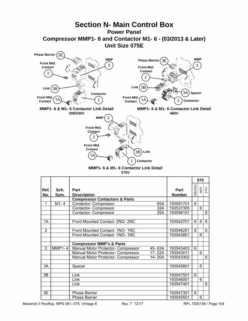
Maverick II Rooftop, MPS 061- 075, Vintage E Rev. T 12/17 RPL 7000158 / Page 104
MMP1- 6 & M1- 6 Contactor Link Detail208/230V
MMP1- 6 & M1- 6 Contactor Link Detail460V
Section N- Main Control BoxPower Panel
Compressor MMP1- 6 and Contactor M1- 6 - (03/2013 & Later)Unit Size 075E
MMP1- 6 & M1- 6 Contactor Link Detail575V
MMP
3Front Mtd.Contact
2
Contactor
1
Link 3B
3EPhase BarrierMMP
2
Contactor1
3
Spacer3A
3EPhase Barrier
Front Mtd.Contact
Link 3B
MMP 3
Contactor1
2
Front Mtd.Contact
Link3B
075
Ref. Sch. Part Part No. Sym. Description Number Compressor Contactors & Parts 1 M1- 4 Contactor- Compressor 65A 193591701 6 Contactor- Compressor 32A 193537305 6 Contactor- Compressor 25A 193598101 6
1A Front Mounted Contact- 2NO- 2NC 193542701 6 6 6
2 Front Mounted Contact- 1NO- 1NC 193546201 6 6 Front Mounted Contact- 1NO- 1NC 193543801 6
Compressor MMP’s & Parts 3 MMP1- 4 Manual Motor Protector- Compressor 45- 63A 193543403 6 Manual Motor Protector- Compressor 17- 22A 193543011 6 Manual Motor Protector- Compressor 14- 20A 193543302 6
3A Spacer 193545801 6
3B Link 193547501 6 Link 193546001 6 Link 193547401 6
3E Phase Barrier 193547301 6 Phase Barrier 193545501 6
208/
230V
460V
575V
Front Mtd.Contact
1A
Front Mtd.Contact 1A
Front Mtd.Contact 1A

Maverick II Rooftop, MPS 061- 075, Vintage E Rev. T 12/17 RPL 7000158 / Page 105
061- 070 075 Ref. Schematic Part Part No. Symbol Description Number Cond. Fan Contactors 1 M11- 14 M21- 24 Contactor- Cond. Fan 193534105 6 6 6 6 8 8 8 8
Fan MMP’s & Parts 3 MMP11- 13 Manual Motor Protector 193542911 3 3 Manual Motor Protector 193542910 3 3 Manual Motor Protector 193542908 3 3 Manual Motor Protector 193542907 3 3 MMP14 Manual Motor Protector 193542911 1 Manual Motor Protector 193542910 1 Manual Motor Protector 193542908 1 Manual Motor Protector 193542907 1 MMP21- 23 Manual Motor Protector 193542911 3 3 Manual Motor Protector 193542910 3 3 Manual Motor Protector 193542908 3 3 Manual Motor Protector 193542907 3 3 MMP24 Manual Motor Protector 193542911 1 Manual Motor Protector 193542910 1 Manual Motor Protector 193542908 1 Manual Motor Protector 193542907 1
3B Link- MMP 193545901 6 6 6 6 8 8 8 8
N/S Bus Bar 193544401 2 2 2 2 N/S Bus Bar 193544501 2 2 2 2
N/S Bus Bar Top Feed 193545101 2 2 2 2 2 2 2 2
208
230V
460V
575V
208
230V
460V
575V
Section N- Main Control BoxPower Panel
Condenser Fan MMP12- 24, Contactors M11- 24, Fuses F11, F21Fantrol Units (Code 47= 1)- (03/2013 & Later)
MMP
3
Link 3B
Contactor1
N/S= Not shown on diagram.

Maverick II Rooftop, MPS 061- 075, Vintage E Rev. T 12/17 RPL 7000158 / Page 106
Section N- Main Control BoxPower Panel
Condenser Fan MMP12- 24, Contactors M11- 24, Fuses F11, F21Speedtrol Units (Code 47= 2)- (03/2013 & Later)
MMP & Contactors Detail Speedtrol FusesMMP
3
Link 3B
Contactor
1
061- 070 075 Ref. Schematic Part Part No. Symbol Description Number Cond. Fan Contactors 1 M11- 14 M21- 24 Contactor- Cond. Fan 193534105 6 6 6 6 8 8 8 8 Fan MMP’s & Parts 3 MMP11- 13 Manual Motor Protector 193542911 3 3 Manual Motor Protector 193542910 3 3 Manual Motor Protector 193542908 3 3 Manual Motor Protector 193542907 3 3 MMP14 Manual Motor Protector 193542911 1 Manual Motor Protector 193542910 1 Manual Motor Protector 193542908 1 Manual Motor Protector 193542907 1 MMP21- 23 Manual Motor Protector 193542911 3 3 Manual Motor Protector 193542910 3 3 Manual Motor Protector 193542908 3 3 Manual Motor Protector 193542907 3 3 MMP24 Manual Motor Protector 193542911 1 Manual Motor Protector 193542910 1 Manual Motor Protector 193542908 1 Manual Motor Protector 193542907 1 3B Link- MMP 193545901 6 6 6 6 8 8 8 8 4 Dinrail Adapter 349938412 2 2 2 2 2 2 2 2 N/S Bus Bar 193544301 1 1 1 1 1 1 1 1 N/S Bus Bar Top Feed 193545101 1 1 1 1 1 1 1 1 Speedtrol Fusing 5 F11, 21 Fuse Block 023780232 2 2 2 2 2 2 2 2 6 Fuse Cover/Puller 349938227 3 3 3 3 3 3 3 3 7 F11, 21 Fuse 1 6 6 6 6
208
230V
460V
575V
208
230V
460V
575V
N/S= Not shown on diagram.1 Contact Daikin Applied with model and serial number information so that the required fuse(s) can be identified.
Fuse BlockFuse
Puller
2
3 1
4Adapter

Maverick II Rooftop, MPS 061- 075, Vintage E Rev. T 12/17 RPL 7000158 / Page 107
Section N- Main Control BoxIntelligent Equipment: Code 23= ****A
Intelligent Equipment™ (IE) from Daikin Applied is a secure, cloud-based solution that enables delivery of information to end users and/or service technicians via the web or mobile device. Intelligent Equipment measures the power and performance of every unit providing real-time data streams for benchmarking performance and monitoring system operation.
A power measurement module and communications gateway installed on Daikin Applied equipment enables the unit to be directly connected to the internet via a wireless connection (Wi-Fi, cellular) or through a local area network (LAN) providing management, monitoring, control, analysis, and decision-making functionality.
Note that this feature may be added to the unit in the field after the initial purchase. In this case, the coding shown above does NOT apply.
Click on this link to access the RPL for Intelligent Equipment: 7000506.
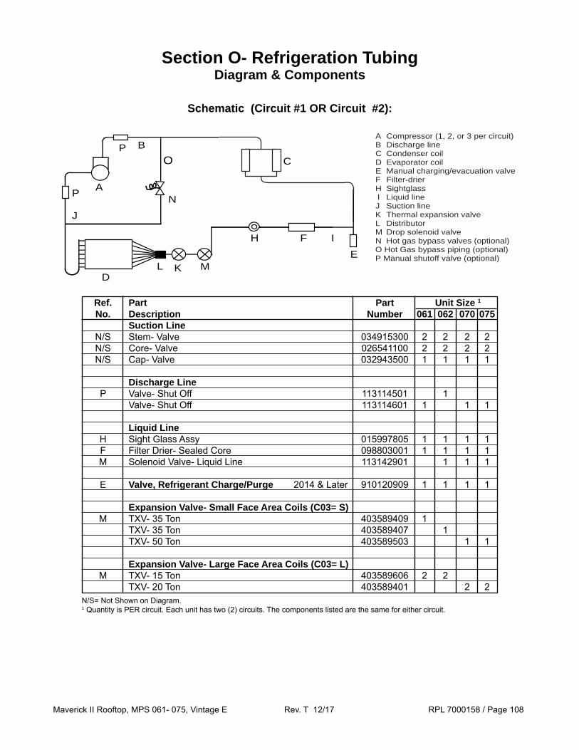
Maverick II Rooftop, MPS 061- 075, Vintage E Rev. T 12/17 RPL 7000158 / Page 108
Ref. Part Part Unit Size 1
No. Description Number 061 062 070 075 Suction Line N/S Stem- Valve 034915300 2 2 2 2 N/S Core- Valve 026541100 2 2 2 2 N/S Cap- Valve 032943500 1 1 1 1
Discharge Line P Valve- Shut Off 113114501 1 Valve- Shut Off 113114601 1 1 1 Liquid Line H Sight Glass Assy 015997805 1 1 1 1 F Filter Drier- Sealed Core 098803001 1 1 1 1 M Solenoid Valve- Liquid Line 113142901 1 1 1
E Valve, Refrigerant Charge/Purge 2014 & Later 910120909 1 1 1 1
Expansion Valve- Small Face Area Coils (C03= S) M TXV- 35 Ton 403589409 1 TXV- 35 Ton 403589407 1 TXV- 50 Ton 403589503 1 1
Expansion Valve- Large Face Area Coils (C03= L) M TXV- 15 Ton 403589606 2 2 TXV- 20 Ton 403589401 2 2
Schematic (Circuit #1 OR Circuit #2):
Section O- Refrigeration Tubing Diagram & Components
N/S= Not Shown on Diagram.1 Quantity is PER circuit. Each unit has two (2) circuits. The components listed are the same for either circuit.
B
A
J
DL K
N
M
H F I
E
P
P
O
A Compressor (1, 2, or 3 per circuit) B Discharge line C Condenser coil D Evaporator coil E Manual charging/evacuation valve F Filter-drier H Sightglass I Liquid line J Suction line K Thermal expansion valve L Distributor M Drop solenoid valve N Hot gas bypass valves (optional) O Hot Gas bypass piping (optional) P Manual shutoff valve (optional)
C
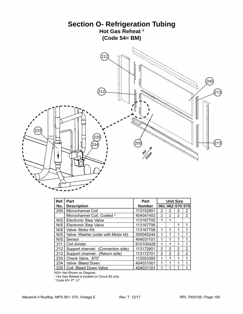
Maverick II Rooftop, MPS 061- 075, Vintage E Rev. T 12/17 RPL 7000158 / Page 109
Section O- Refrigeration Tubing Hot Gas Reheat 1
(Code 54= BM)
200
213
213
212
212
200
Ref. Part Part Unit Size No. Description Number 061 062 070 075 200 Microchannel Coil 113152801 2 2 2 2 Microchannel Coil, Coated 2 404047402 2 2 2 2 N/S Electronic Step Valve 113167705 1 1 N/S Electronic Step Valve 113167706 1 1 N/S Valve- Motor Kit 113167708 1 1 1 1 N/S Valve- Washer (order with Motor kit) 300045244 1 1 1 1 N/S Sensor 404031101 1 1 1 1 211 Coil divider 910100428 1 1 1 1 212 Support channel- (Connection side) 113172601 2 2 2 2 213 Support channel- (Return side) 113172701 2 2 2 2 233 Check Valve, .875” 112053305 1 1 1 1 234 Valve- Bleed Down 404031001 1 1 1 1 235 Coil- Bleed Down Valve 404031101 1 1 1 1
AirFl
ow
233235
234
N/S= Not Shown on Diagram.1 Hot Gas Reheat is located on Circuit #2 only.2 Code 43= P*, U*.