markku tapiovaara, teemu siiskonen - etusivu
TRANSCRIPT
TR
PCXMC 2.0User’s Guide
Markku Tapiovaara, Teemu Siiskonen
STUK-TR 7 / NOVEMBER 2008
SäteilyturvakeskusStrålsäkerhetscentralen
Radiation and Nuclear Safety Authority

STUK • SÄTEILYTURVAKESKUSSTRÅLSÄKERHETSCENTRALEN
RADIATION AND NUCLEAR SAFETY AUTHORITY
Osoite/Address • Laippatie 4, 00880 HelsinkiPostiosoite / Postal address • PL / P.O.Box 14, FIN-00881 Helsinki, FINLANDPuh./Tel. (09) 759 881, +358 9 759 881 • Fax (09) 759 88 500, +358 9 759 88 500 • www.stuk.fi
STUK-TR 7 / NOVEMBER 2008
PCXMC 2.0User's Guide
Markku Tapiovaara, Teemu Siiskonen

ISBN 978-952-478-392-7 (print)ISBN 978-952-478-393-4 (pdf)ISSN 1796-7171

STUK-TR 7
3
Abstract
PCXMC is a computer program for calculating patients’ organ doses and the effective dose in medical x-ray examinations. It allows a free adjustment of the x-ray projection and other examination conditions of projection radiography and fluoroscopy. The anatomical data are based on the mathematical hermaphrodite phantom models of Cristy and Eckerman (1987), with some modifications and user-adjustable phantom sizes. The program also calculates the risk of death for radiation-induced cancers. This User’s Manual explains how to use the program (version 2.0). The technical documentation of the program is published in report STUK-A231, which describes the concepts, methods and data used in PCXMC 2.0.
TAPIOVAARA Markku, SIISKONEN Teemu. PCXMC 2.0. User's Guide. STUK-TR 7. Helsinki 2008. 19 pp. + apps. 5 pp.
Key words: PCXMC, x-ray diagnostics, patient dose, effective dose, organ dose, Monte Carlo method, risk assessment, computer program

4
STUK-TR 7
Contents
AbSTrACT 31 GEnErAl 52 ProGrAM InSTAllATIon on hArd dISK 63 USInG ThE ProGrAM 7
3.1 MAIn MEnU bUTTon: Examination data 83.1.1 Examination data input form: Field size calculator 11
3.2 MAIn MEnU bUTTon: Simulate! 113.3 MAIn MEnU bUTTon: Compute doses 123.4 MAIn MEnU bUTTon: risk assessment 153.5 MAIn MEnU bUTTon: About 183.6 MAIn MEnU bUTTon: Exit 18
4 rEFErEnCES 19
Appendix 1 File types oF pCxMC 20Appendix 2 Using the AUtoMAtiC FeAtUres oF the pCxMC 2.0 21
Note on the use of various fonts in this document:
Names of items (buttons, edit boxes etc.) on the forms are printed in italic font. Text that we wish to highlight is printed in bold font. Text depicting data in a text file is printed using Courier.

STUK-TR 7
5
1 General
PCXMC is a computer program for calculating patients’ organ doses and effective doses in medical x-ray examinations (radiography and fluoroscopy). The organ doses are calculated in 29 organs and tissues. The program calculates the effective dose with both the new tissue weighting factors of ICrP Publication 103 (2007) and the old tissue weighting factors of ICrP Publication 60 (1991). The program incorporates adjustable-size paediatric and adult patient models, and allows a free choice of the x-ray examination technique. The program also calculates an estimate of the patient’s risk of death due to radiation-induced cancer according to the sex- and age-dependent risk model of the bEIr VII committee (bEIr 2006). For a more thorough explanation of the calculation details of the program, see the folder …\PCXMC\Manuals in your PC, where a technical program document (Tapiovaara and Siiskonen 2008) is saved during program installation. This document can also be found in the web pages of the program: http://www.stuk.fi/pcxmc. This User’s Manual concentrates only on the use of the program.
PCXMC 2.0 differs from the previous version 1.5.2 in a few respects: • The error in the x-ray spectrum calculation
(excess number of photons in the lowest energy bin when the x-ray tube total filtration consisted only of heavy elements) has been corrected.
• The phantom data have been updated fromCristy (1980) to those of Cristy and Eckerman (1987) with some additional modifications.
• Theshapeofthephantoms’headandneckhavebeen improved to better resemble the shape of humans.
• Neworgansandtissues(extrathoracicairways,lymph nodes, oral mucosa, prostate and salivary glands) have been added.
• The calculation of the effective dose is nowmade according to both the previous ICrP 60 (1991) tissue weighting factors and the present ICrP 103 (2007) tissue weighting factors.
• Anewfeatureintheprogramisthatitisnowable to perform automated computation of doses without user interference during the calculation. This feature is explained in Appendix 2.
• Anothernewfeatureintheprogramisthatitisnow able to estimate the patient’s risk of death by radiation-induced cancer.
The input data files (*.def) of the earlier PCXMC versions are mostly compatible with version 2.0; however, the z-coordinates of the head and neck of the phantoms are now somewhat changed from the earlier phantom models and, therefore, the user needs to check the appropriateness of the beam location and beam edges in cases where these body parts are involved. The program notifies the user on this if input data files of earlier PCXMC versions are opened. The energy files (i.e., Monte Carlo simulation results, *.ene) or dose files (*.mGy) of the old versions cannot be opened with the new version: the results need be resimulated if calculations with the new program version are needed.
PCXMC 2.0 runs under Microsoft Windows 32 bit operating systems (Windows95/98/nT/2000/XP/Vista). A PC equipped with a processor of at least 120 Mhz clock rate is needed for the use of the program, but a more powerful PC is recommended for shorter calculation times. The examination data input form needs a desktop area of at least 1024 x 768 to be fully visible.
6
STUK-TR 7
2 Program installation on hard disk
If you have an older version of PCXMC in your computer you can keep it or uninstall it, according to your preference. The new version can be installed in the same folder as the previous version: the different versions do not cause any problems to each other. If you wish to remove the old version, you should do it before installing the new version. otherwise, if you uninstall the old version later, some files that are common to both versions will be deleted and the program does not work properly.
To install the program in your PC from the PCXMC 2.0 Installation disk follow the instructions below: • Put the PCXMC 2.0 Installation Disk in the
Cd-roM drive.• Run the PCXMC20_Setup.exe program on
the installation disk; this is the installation program of PCXMC, and it will guide you through the rest of the installation procedure. The installation program will suggest C:\Program Files\PCXMC as the folder where the program and data will be put. If you wish, you can install the program also elsewhere.
• Duringinstallation,ashort-cuttotheprogramis added to your desktop. The default working directory of the program is …\PCXMC\MCrUnS, which is created during installation;
this directory is suggested for keeping the data that you’ll generate when using the program. It may happen that this default directory is not set properly when you first run the program. In this case you can restore this default working directory by choosing Restore default directory in the File-menu in the Examination data form (which is described in section 3.1).
• Forbestgraphicsquality,setthedisplaymodeof your PC to use at least 16 bit colour depth (65536 colours); in the 8-bit display mode the graphics in the program will be of poor quality due to the small number of available colors. The desktop size should be at least 1024 x 768. If the desktop size is too small, horizontal and vertical scroll bars are created. however, the images on the examination data input form will not be shown properly, and using the program becomes cumbersome. Use normal or small fonts in the desktop settings of your PC; large fonts may cause improper visibility of some forms of the program in some operating systems.
• The installation program puts a copy of thisUser’s Manual, the Terms and Conditions of Use and the technical program document in the directory …\PCXMC\Manuals.
STUK-TR 7
7
3 Using the program
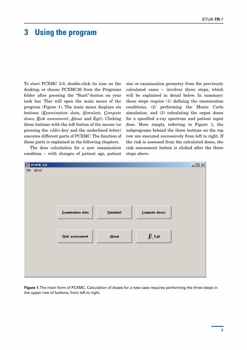
To start PCXMC 2.0, double-click its icon on the desktop, or choose PCXMC20 from the Programs folder after pressing the “Start”-button on your task bar. This will open the main menu of the program (Figure 1). The main menu displays six buttons (Examination data, Simulate, Compute doses, Risk assessment, About and Exit). Clicking these buttons with the left button of the mouse (or pressing the <Alt>-key and the underlined letter) executes different parts of PCXMC. The function of these parts is explained in the following chapters.
The dose calculation for a new examination condition – with changes of patient age, patient
size or examination geometry from the previously calculated cases – involves three steps, which will be explained in detail below. In summary: these steps require (1) defining the examination conditions, (2) performing the Monte Carlo simulation, and (3) calculating the organ doses for a specified x-ray spectrum and patient input dose. More simply, referring to Figure 1, the subprograms behind the three buttons on the top row are executed successively from left to right. If the risk is assessed from the calculated doses, the risk assessment button is clicked after the three steps above.
Figure 1. The main form of PCXMC. Calculation of doses for a new case requires performing the three steps in the upper row of buttons, from left to right.
8
STUK-TR 7
If the patient data (age, weight, height) and the geometric data of the examination are unchanged from a previous calculation one does not need to perform the first two of the above steps, and the patient dose calculation is accomplished by performing the step (3) only. That is, the user does not need to perform the Monte Carlo simulation again, if just the x-ray spectrum or the amount of radiation have changed.
The program produces files of different extensions. The program adds these extensions automatically and keeps track of the files. Therefore, do not use any extensions for the file names that you save in PCXMC. Files containing the examination and patient parameters for Monte Carlo simulation (definition files) use the extension '.df2', data files produced by the Monte Carlo calculation (energy files) use the extension '.en2', and the final dose results for specific x-ray spectra and input dose (dose files) use the extension '.mG2'. The risk assessment reports use the extension ‘.txt’. Input files from the earlier versions of PCXMC used the extension '.def' for definition files; if the user opens such a file, the program prompts for the need to check the appropriateness of the beam location and changes the extension. The checked definition file should then be saved for subsequent use by clicking the ‘Save Form’ or ‘Save Form As…’ button. For a more detailed explanation of the file types, see Appendix 1 of this manual.
We recommend that the above files (definition files, energy files and dose files) are kept in the directory PCXMC\MCrUnS or that the user creates new subdirectories in this directory for organising the data. This working directory can be restored by choosing Restore default directory in the File-menu of the Examination data form. In this version (PCXMC 2.0) there are a few readily calculated Monte Carlo data sets, which are located in subfolders of MCrUnS. The data have been organised by the age of the patient and are for typical common projections.
3.1 MAIN MENU BUTTON: Examination dataClicking this button opens a form (see Figure 2) where the user defines the x-ray examination
conditions and the phantom model which will be used in the subsequent Monte Carlo simulation. The data are saved as a definion file (*.df2) when the editing is complete.
The title bar (at the top of the form) shows the file name and full path of the opened definition file. If no file has been specified there is no text between the brackets.
on the first data row there is an input field displaying the 'header text'. This data field can be used for a short user-typed text to further explain the simulation conditions.
If the Monte Carlo data have already been calculated for an opened definition file, there will appear a text on yellow background above the header input field notifying this. In this case, the user must save the data using another definition file name after editing the data. renaming will be prompted when the user will try to save the changed definition file or exit the examination data input form.
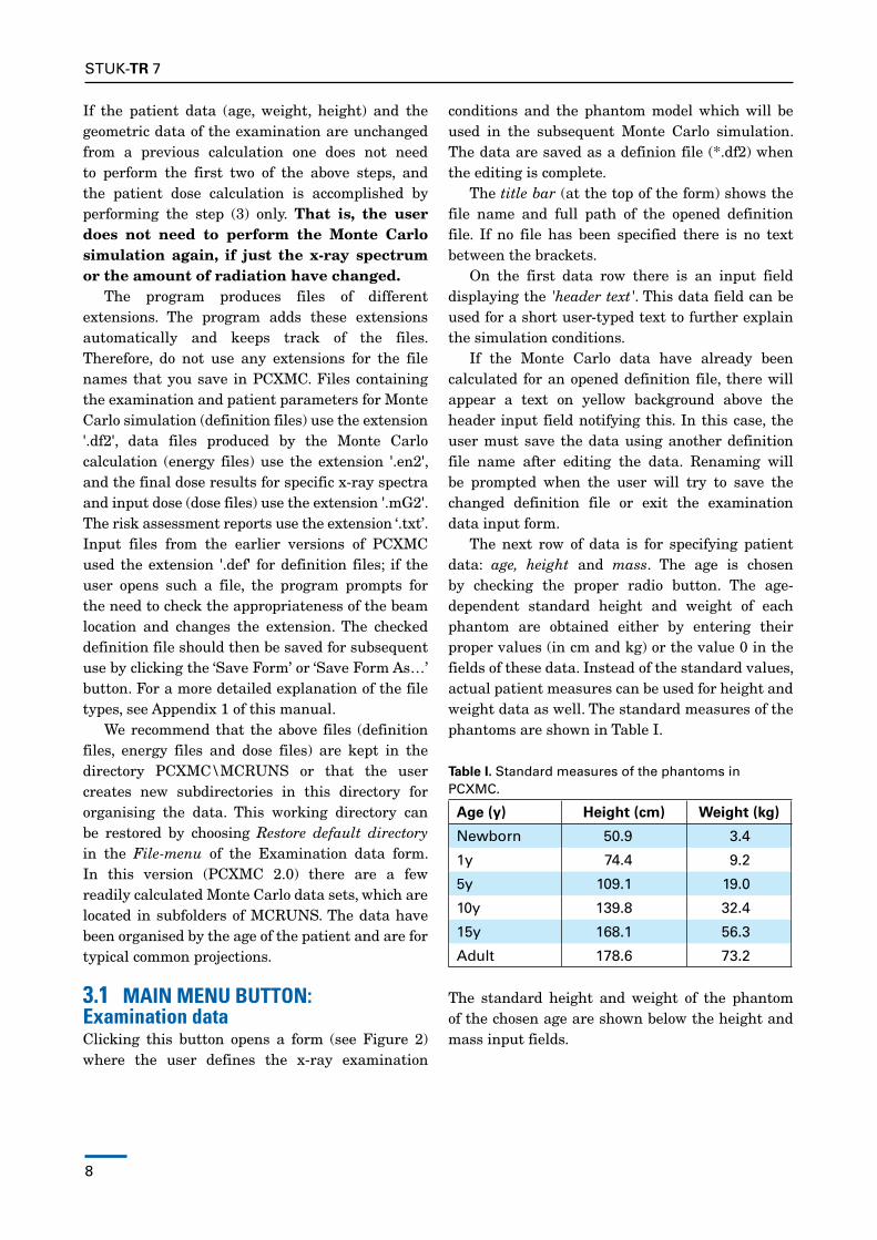
The next row of data is for specifying patient data: age, height and mass. The age is chosen by checking the proper radio button. The age-dependent standard height and weight of each phantom are obtained either by entering their proper values (in cm and kg) or the value 0 in the fields of these data. Instead of the standard values, actual patient measures can be used for height and weight data as well. The standard measures of the phantoms are shown in Table I.
Table I. Standard measures of the phantoms in PCXMC.
Age (y) Height (cm) Weight (kg)
Newborn 50.9 3.4
1y 74.4 9.2
5y 109.1 19.0
10y 139.8 32.4
15y 168.1 56.3
Adult 178.6 73.2
The standard height and weight of the phantom of the chosen age are shown below the height and mass input fields.
STUK-TR 7
9
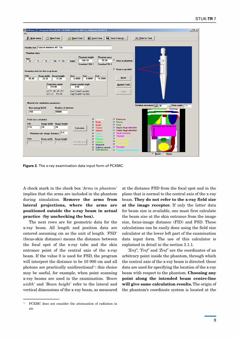
Figure 2. The x-ray examination data input form of PCXMC.
A check mark in the check box 'Arms in phantom' implies that the arms are included in the phantom during simulation. Remove the arms from lateral projections, where the arms are positioned outside the x-ray beam in actual practice (by unchecking the box).
The next rows are for geometric data for the x-ray beam. All length and position data are entered assuming cm as the unit of length. 'FSD' (focus-skin distance) means the distance between the focal spot of the x-ray tube and the skin entrance point of the central axis of the x-ray beam. If the value 0 is used for FSd, the program will interpret the distance to be 10 000 cm and all photons are practically unidirectional*): this choice may be useful, for example, when point scanning x-ray beams are used in the examination. 'Beam width' and 'Beam height' refer to the lateral and vertical dimensions of the x-ray beam, as measured
*) PCXMC does not consider the attenuation of radiation in air.
at the distance FSd from the focal spot and in the plane that is normal to the central axis of the x-ray beam. They do not refer to the x-ray field size at the image receptor. If only the latter data for beam size is available, one must first calculate the beam size at the skin entrance from the image size, focus-image distance (FId) and FSd. These calculations can be easily done using the field size calculator at the lower left part of the examination data input form. The use of this calculator is explained in detail in the section 3.1.1.
‘Xref’, ‘Yref’ and ‘Zref’ are the coordinates of an arbitrary point inside the phantom, through which the central axis of the x-ray beam is directed: these data are used for specifying the location of the x-ray beam with respect to the phantom. Choosing any point along the intended beam centre-line will give same calculation results. The origin of the phantom’s coordinate system is located at the

10
STUK-TR 7
centre of the bottom of the phantom trunk section. The positive z-axis is directed upwards, the positive y-axis to the back of the phantom, and the positive x-axis to the left-hand side of the phantom.
The graphics capabilities – the phantom image and the ‘radiograph’ – can be used as a guidance in finding proper coordinates for the reference point. The reference point can be most easily edited by clicking the mouse within either the phantom image or the radiograph. In the former case the reference point will be put just below the phantom surface at the position of the cursor when the button is clicked, and in the latter case the reference point is put below the surface of the organ clicked.
‘Projection angle’ and ‘Cranio-caudal angle’ specify the direction of the x-ray beam with respect to the phantom. The first of these angles specifies whether the x-ray beam enters the patient from the front or back-side (or at any other angle), i.e., it describes rotations in the xy-plane and the latter angle specifies the tilting of the beam with respect to the xy-plane. All angles are given in degrees. It is suggested that the user checks his/her proper entering of these angles from the phantom image.
The check-box 'Draw x-ray field' is used to control whether the x-ray beam edges are shown in the phantom image. It is useful to keep this box checked; one might wish to leave the image without beam indication only in special occasions. This selection has no effect on the calculation results.
The next row of data is for simulation details: the maximum photon energy of interest and the number of photons in the simulation. The maximum energy that will be used in the Monte Carlo simulation is typed in the field Max energy. Maximum energy equal to 90 corresponds to a maximum allowable x-ray tube potential of 90 kV in subsequent dose calculations. Unless calculation speed is of great concern, we suggest that this value is kept at its maximum, Max energy = 150, in order not to limit the allowable x-ray tube voltages. Number of photons is a main factor in determining the statistical precision that will be achieved in the Monte Carlo simulation: it represents the number of photon histories that will be generated. For this parameter we recommend a minimum value of 10 000. The program adjusts
the number to the multiples of 100. If Max energy is set to 150 keV and Number of photons is 20 000, the simulation requires typically about 30 seconds of computation time on a PC with a 1.8 Ghz processor. The calculation time can be shortened by specifying a lower value for Max energy (which then restricts the use of the data for x-ray tube voltages higher than this value in kilovolts), or Number of photons (which then results in larger stochastic uncertainties in the data).
Clicking the button 'New Form' initialises the input form data to a default set. 'Open Form' shows all files with the extension '.df2' or '.def' and allows the user to open any of them in order to modify or view the data. After editing the data, they can be saved by clicking the 'Save Form' or 'Save Form As…' buttons. note that if the data have already been used in simulation (which is indicated by the yellow-backed text above the header text) the definition file must be saved with a new file name to avoid discrepant data files from being created. do not explicitly type the extension, the program will add it automatically. In PCXMC 2.0 there is one reserved definition file name (Autocalc.df2) that the user should not use here (this would result in cutting the necessary data from the file, and result to I/O errors when trying to use these files). The use of Autocalc.df2 is explained in Appendix 2.
The user can print the data by clicking the 'Print as text' button. The user can return to the main form by clicking the 'Main menu' button or by using the ‘File’ menu.
Clicking the 'Draw' -button displays the currently specified phantom and examination geometry (see Figure 2). If the examination data have been modified without clicking this button, there will appear a yellow warning text on the form noting that the images do not correspond to the data on the form. This message text disappears when the Draw button is clicked. The phantom image will also show the edges of the x-ray beam if the box 'Draw x-ray field' is checked. Those parts of the x-ray field that hit the phantom are indicated in red colour and parts that do not intersect the phantom are shown as green. The background colour of the image is the same as is set for the 'Active Title bar' in the Windows Control Panel
STUK-TR 7
11
colour settings. You can move the cursor over the phantom image to see the coordinates of the cursor point on the phantom surface, and you can rotate the phantom by any angle to see it from different directions (editing of the ‘Rotation increment’ is allowed). This rotation of the image can be done by pressing the ‘+’ or ‘–‘ buttons. The input data or the calculation results are not changed by the above operations, they affect only the phantom image display on this form.
Clicking the 'Update Field' button causes the formerly specified beam edges to be colored gray, and the newly specified beam edges to be shown with the colors explained above. The 'Stop' button can be used for stopping the drawing procedure.
After drawing the phantom image, the program draws also a simulated 'radiograph' which shows the organs in the defined x-ray beam as viewed from the x-ray tube focal spot: this picture mimics the x-ray image of the specified examination conditions. Those parts in the radiograph that are outside the phantom or x-ray field are displayed black, parts that belong to the phantom but not to any of the (checked) organs in the organ list are displayed grey. other colours correspond to the first organ in the path of a photon, and are equal to the colours of the organ names in the list. The user can check and uncheck organs to be displayed. The user can choose whether the displayed radiograph is drawn with higher detail or more quickly by choosing the 'Quick' or 'Sharp' radio-button. The input data and the calculation results are not changed by these choices, they affect only the radiograph image display on this form. The x-ray beam location can be edited similarly as in the phantom image by clicking on the image in an area depicting a specified organ (color other than black or grey). The clicked cursor position will then be the new x-ray field centre.
3.1.1 Examination data input form: Field size calculatorThe field size calculator calculates the FSd and the width and height of the x-ray beam at the patient's
entrance. To use the calculator, one must know and enter the x-ray beam size at the image receptor plane (i.e. the width and height of the actual x-ray image), the distance between the x-ray tube focal spot and the image receptor (FId), and the distance between the patient's exit surface and the image receptor (which can be typically of the order of 10 cm in bucky tables). The thickness of the patient is calculated by the program, when the user clicks the 'Calculate' button. The patient thickness thus obtained corresponds to the phantom, x-ray beam location and direction data specified in their appropriate input fields on the examination data input form. The calculated FSd and beam size data are copied to their input fields when the user clicks the 'Use this data' button. Unless this button is pressed, the data entered in the field size calculator do not influence the input data or calculation results.
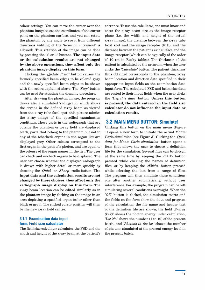
3.2 MAIN MENU BUTTON: Simulate!Clicking this button on the main menu (Figure 1) opens a new form to initiate the actual Monte Carlo simulation (see Figure 3). Clicking the 'Open data for Monte Carlo simulation' button opens a form that allows the user to choose a definition file for the simulation. Several files can be chosen at the same time by keeping the <Ctrl> button pressed while clicking the names of definition files, or by keeping the <Shift> button pressed while selecting the last from a range of files. The program will then simulate these conditions one after another automatically, without user interference. For example, the program can be left simulating several conditions overnight. When the 'OK' button is clicked, the simulation starts and the fields on the form show the data and progress of the calculation: the file name and header text of the definition file are shown, the field 'Energy (keV)' shows the photon energy under calculation, 'Lot No' shows the number (1 to 10) of the present batch, and 'Photons in the lot' shows the number of photons simulated at the present energy level in the present batch.
12
STUK-TR 7
Figure 3. The Monte Carlo simulation form of PCXMC.
The simulation can be stopped at any stage by clicking the 'Stop simulation' button, but then all simulation data of the present simulation run are lost; if several simulations have been specified, the completed simulations are saved. The calculation is ready when a message box with text 'done' is displayed. The user can then return to the main form by clicking the 'Main menu' button.
The results of the simulation are automatically stored under the same name as the definition file of the simulation conditions, but the extension '.df2' is replaced by '.en2'. This file is then used for calculating the organ doses for any x-ray spectrum or input dose that the user is interested in, without the need to make new simulations, as long as all other examination parameters are kept unchanged.
note that when the program is used for the first time for calculating doses in a phantom of a specified age, it automatically creates additional data in the directory \PCXMC\MCIndATA\
GrIdS and may prompt the user to wait for the completion of this operation. This operation is not done in later simulations.
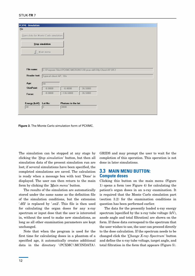
3.3 MAIN MENU BUTTON: Compute dosesClicking this button on the main menu (Figure 1) opens a form (see Figure 4) for calculating the patient’s organ doses in an x-ray examination. It is required that the Monte Carlo simulation part (section 3.2) for the examination conditions in question has been performed earlier.
The data for the presently loaded x-ray energy spectrum [specified by the x-ray tube voltage (kV), anode angle and total filtration] are shown on the form. If these data correspond to the spectrum that the user wishes to use, the user can proceed directly to the dose calculation. If the spectrum needs to be changed click the 'Change X-ray Spectrum' button and define the x-ray tube voltage, target angle, and total filtration in the form that appears (Figure 5).
STUK-TR 7
13
Figure 4. The dose calculation form of PCXMC. The table is empty before a file has been opened.
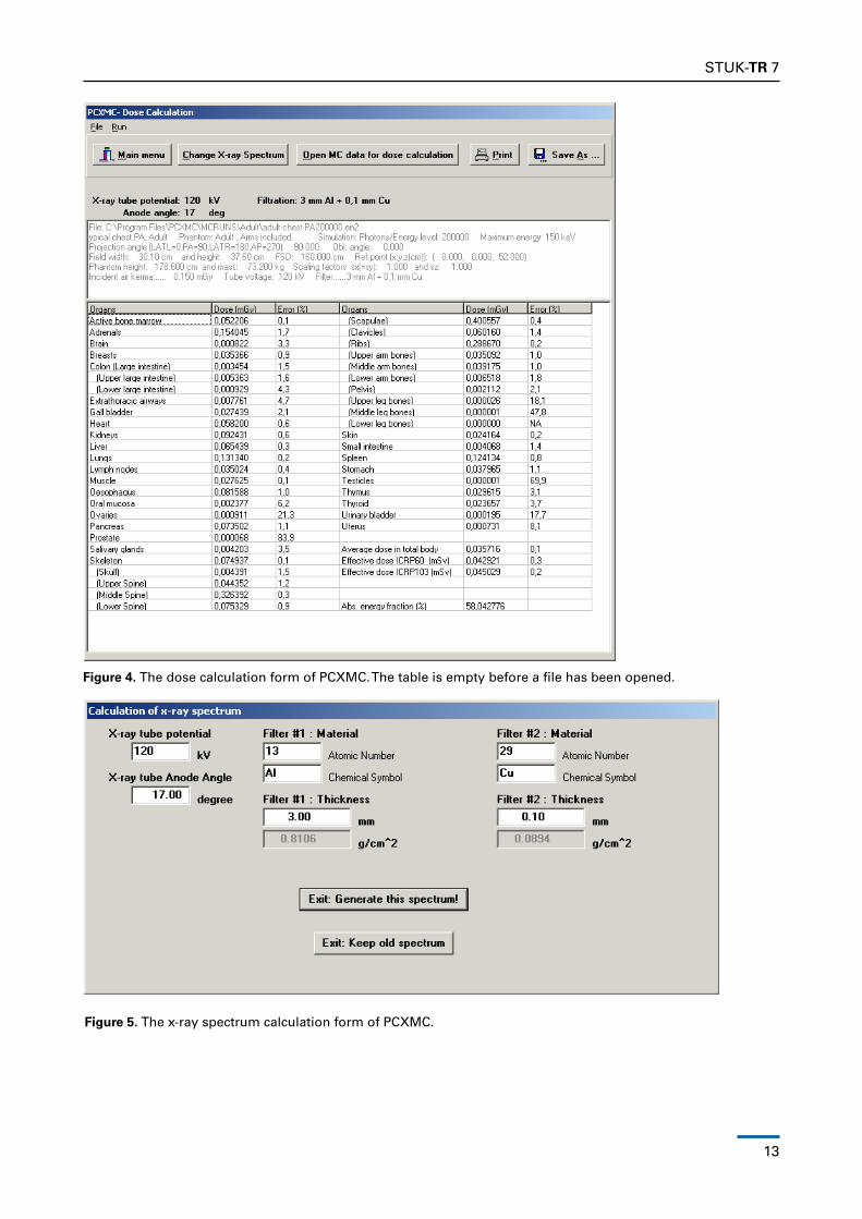
Figure 5. The x-ray spectrum calculation form of PCXMC.
14
STUK-TR 7
In PCXMC, x-ray tube filtration is specified by two different filters of arbitrary elemental materials. These elements are chosen by entering their atomic number or chemical symbol in their proper fields. note that when entering either of these data, the other is updated simultaneously. If the chemical symbol is used, the program requires that it is typed with the proper upper- and lower-case lettering, e.g. Cu for copper. If only one filter material is used, the atomic number of filter #2 should be set equal to 0, or the chemical symbol of it should be cleared. The filter thickness must be input in units of mm. The program automatically calculates the mass thickness of the filter in units of g/cm2 according to the filter material and thickness. The user cannot edit this field, but it can be used as guidance if filtration is specified in terms of the mass thickness. The new spectrum will be calculated and used (until the user specifies a new spectrum) when the user clicks the 'Exit: Generate this spectrum!' button. The changes are discarded if the button ‘Exit: Keep old spectrum’ is clicked.
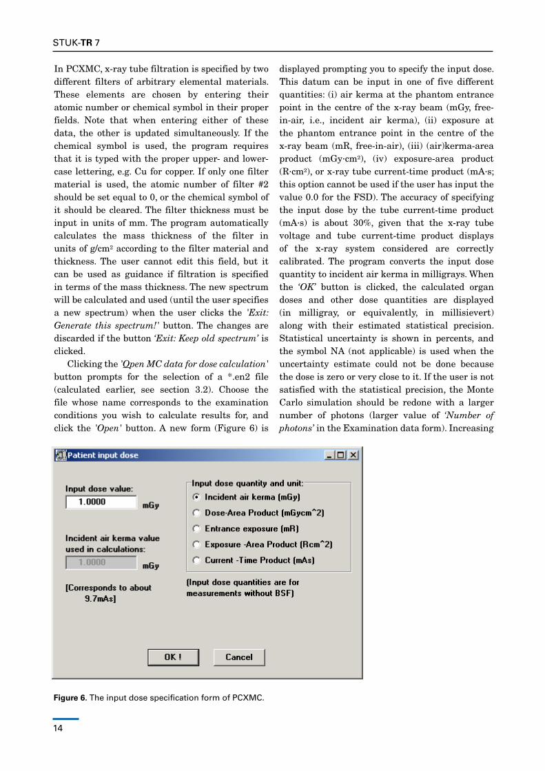
Clicking the 'Open MC data for dose calculation' button prompts for the selection of a *.en2 file (calculated earlier, see section 3.2). Choose the file whose name corresponds to the examination conditions you wish to calculate results for, and click the 'Open' button. A new form (Figure 6) is
displayed prompting you to specify the input dose. This datum can be input in one of five different quantities: (i) air kerma at the phantom entrance point in the centre of the x-ray beam (mGy, free-in-air, i.e., incident air kerma), (ii) exposure at the phantom entrance point in the centre of the x-ray beam (mr, free-in-air), (iii) (air)kerma-area product (mGy∙cm2), (iv) exposure-area product (r∙cm2), or x-ray tube current-time product (mA∙s; this option cannot be used if the user has input the value 0.0 for the FSd). The accuracy of specifying the input dose by the tube current-time product (mA∙s) is about 30%, given that the x-ray tube voltage and tube current-time product displays of the x-ray system considered are correctly calibrated. The program converts the input dose quantity to incident air kerma in milligrays. When the ‘OK’ button is clicked, the calculated organ doses and other dose quantities are displayed (in milligray, or equivalently, in millisievert) along with their estimated statistical precision. Statistical uncertainty is shown in percents, and the symbol nA (not applicable) is used when the uncertainty estimate could not be done because the dose is zero or very close to it. If the user is not satisfied with the statistical precision, the Monte Carlo simulation should be redone with a larger number of photons (larger value of ‘Number of photons’ in the Examination data form). Increasing
Figure 6. The input dose specification form of PCXMC.
STUK-TR 7
15
the value of ‘Number of Photons’ by a factor of four approximately halves the error.
It should be noted that the accuracy of both the dose estimate and its statistical error depend on the number of simulated interactions in the organ considered. The number of interactions may be low even for a large number of photon histories if the dose in the organ is low and/or the organ is small. It should also be noted that when the number of interactions is small, which is indicated by a high value of the statistical uncertainty (several tens of percents), the estimate has a skewed non-normal distribution and the actual statistical errors may be significantly larger than expected on the basis of the standard deviation. however, it should be understood that the statistical error is usually a small factor in the total uncertainty of the results. The differences between the phantom and the actual patient, and the differences between the simulated and true geometry will often dominate.
'Save As…' saves the dose data in a file by the name that the user supplies (these files are saved using the default extension '.mG2'). 'Print' is used for sending the dose data to a printer. Again, clicking 'Main menu' takes the user back to the main menu. If you wish to use the calculated dose data in risk assessment (section 3.4), you must save the data here before performing the risk calculation.
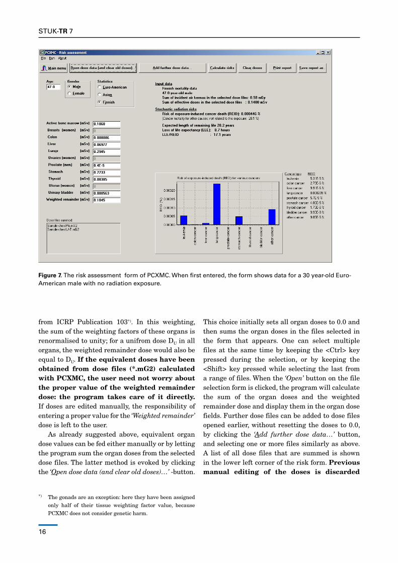
3.4 MAIN MENU BUTTON: Risk assessmentClicking this button on the main menu (Figure 1) opens a form (see Figure 7) for assessing the risk of radiation-induced cancer death. PCXMC also notifies the user, if high doses – that may be capable of causing deterministic health effects – are found. PCXMC does not assess the genetic
harm from the radiation exposure of the gonads. For such effects, see ICrP Publication 103.
noTE: Many mathematical models have been developed for estimating the cancer risk resulting from an exposure to ionising radiation; PCXMC uses the model developed by the bEIr VII committee (Committee on the biological Effects of Ionizing radiations, bEIr 2006). Many factors, e.g. limitations in the epidemiologic data, contribute to the uncertainty of the risk estimation. The bEIr VII committee suggests that the risk estimates should be regarded with a healthy scepticism, placing more emphasis on the magnitude of the risk. The committee estimates that the excess cancer mortality to solid cancers due to radiation can be estimated within a factor of two (at 95% confidence level). For leukaemia the corresponding factor is four. For individual solid cancer sites the risk estimation may have large uncertainties, up to an order of magnitude or more (bEIr 2006).
In order to assess the risk of radiation-induced cancer death for a given patient, the user needs to enter correct patient data for the ‘Age’, ‘Gender’ and mortality ‘Statistics’ (Euro-American, Asian or Finnish)*) of the patient. The risk assessment is based on the equivalent doses**) shown in the fields on the left side of the form. one may enter the values manually or get them from previously calculated dose files (*.mG2, see section 3.3). Some mortality statistics data do not contain specified cancer statistics for all of the listed organs. Such organs are marked with (*) on the form; doses for these organs are then not directly used in the risk assessment. Instead, the risk assessment of such organs, and other organs not shown in the list, is made using the Weighted remainder dose. This dose represents the weighted equivalent dose of such ‘other organs’ with the tissue weighting factors
*) The Asian and Euro-American mortality data are from ICrP Publication 103, and do not necessarily correspond to the average mortality statistics of all countries in these regions or the specific mortalitity statistics of individual countries in these regions.
**) The equivalent dose of an organ in mSv is numerically equal to the mean absorbed dose in that organ in mGy for photon or electron irradiation. For other radiations, such as, e.g., neutrons, the radiation weighting factor deviates from unity, and must be taken into account when inputting the organ equivalent doses.
16
STUK-TR 7
Figure 7. The risk assessment form of PCXMC. When first entered, the form shows data for a 30 year-old Euro-American male with no radiation exposure.
from ICrP Publication 103*). In this weighting, the sum of the weighting factors of these organs is renormalised to unity; for a unifrom dose dU in all organs, the weighted remainder dose would also be equal to dU. If the equivalent doses have been obtained from dose files (*.mG2) calculated with PCXMC, the user need not worry about the proper value of the weighted remainder dose: the program takes care of it directly. If doses are edited manually, the responsibility of entering a proper value for the ‘Weighted remainder’ dose is left to the user.
As already suggested above, equivalent organ dose values can be fed either manually or by letting the program sum the organ doses from the selected dose files. The latter method is evoked by clicking the ‘Open dose data (and clear old doses)…’ -button.
*) The gonads are an exception: here they have been assigned only half of their tissue weighting factor value, because PCXMC does not consider genetic harm.
This choice initially sets all organ doses to 0.0 and then sums the organ doses in the files selected in the form that appears. one can select multiple files at the same time by keeping the <Ctrl> key pressed during the selection, or by keeping the <Shift> key pressed while selecting the last from a range of files. When the ‘Open’ button on the file selection form is clicked, the program will calculate the sum of the organ doses and the weighted remainder dose and display them in the organ dose fields. Further dose files can be added to dose files opened earlier, without resetting the doses to 0.0, by clicking the ‘Add further dose data…’ button, and selecting one or more files similarly as above. A list of all dose files that are summed is shown in the lower left corner of the risk form. Previous manual editing of the doses is discarded
STUK-TR 7
17
when doses are retrieved by using either of these dose data retrieval buttons. Manual editing has an effect only if it is done as the last step before assessing the risk.
If some of the doses are exceptionally high (above 10 Sv), the corresponding fields will be coloured yellow, and if the dose is too high for a successful calculation, the colour of the field is red. These colour indications should not be directly interpreted as showing the usability of the risk model. They are displayed for technical purposes only.
When all input data (age, gender, statistics and equivalent organ doses) have been specified, the user will get the risk assessment by clicking the ‘Calculate risks’ button. A yellow warning label ‘Risk data have not been updated: Click “Calculate risks”‘ on the form indicates that input data have been edited, and do not anymore match with the risk data displayed on the form. The data are updated and this warning label disappears when the user clicks the ‘Calculate risks’ button or that label.
The risk estimate shows the exposed person’s risk of exposure induced cancer death (rEId), the expected length of his/her remaining life, the mean loss-of-life (llE) and the mean loss of life in case that the radiation induced cancer is realised (llE/rEId). The window also shows a bar chart of the probability (the site-specific rEId value) of various radiation-induced cancer types. This bar chart can be copied to Windows’ Clipboard by double-clicking on it. The natural (i.e., not related to the exposure in question) cancer mortality for the selected gender and statistics is also shown below the risk estimates.
It is noted that the cancer and mortality data used in PCXMC are mostly given in five-year intervals. however, constant values are used for all ages above 90 years. Therefore, taking into account the fact that mortality increases with age and the latency period of radiation-induced cancers, the risk assessment results of persons above around 80 years of age are numerically higher than would be obtained if actual age-dependent mortality data were available for the highest age group. If needed, the user may edit the data files that depict mortality and cancer incidence statistics, for example to improve the data for the highest age groups or to use the statistics of his/her own
country (for details, see appendix 1).The solid cancer risk models use the dose and
dose rate effectiveness factor (ddrEF) of 1.5 (bEIr 2006). If equivalent tissue doses above 50 mSv are involved in the risk assessment, this value of the ddrEF may be inappropriate, and the program notifies this below the risk estimate. If the use of ddrEF equal to 1.5 is considered inappropriate, the solid cancer risks should be multiplied by 1.5. The dose level of the notification can be changed by editing the corresponding datum in the file Warningdoses.dat which is located in the folder \PCXMC\MCIndATA\rISKdATA.
In order to warn for exceptionally large doses, the program also notifies the user if such doses are found. If the sum of incident air kermas from the dose files is larger than 1 Gy, the user is noted on this and he/she may wish to check whether the various x-ray fields in these irradiations overlap to such a degree that deterministic skin effects are possible. note that if the sum of the incident doses is not above 1 Gy, not even small parts of any organs will have local doses much in excess of 1 Gy, regardless of the overlapping of the various fields. The program also checks if the average absorbed dose in any of the organs considered in PCXMC is larger than 1 Gy, and notifies the user by giving one example of such an organ (all such doses can be viewed by printing or saving the risk report, see below). A further check is made of the average doses in various bones (or bone groups) considered in PCXMC. If the average dose in any of them exceeds 3 Gy, the program notifies the user on this. The program also notifies the user if the dose in the uterus of a woman in child-bearing age exceeds 100 mGy. In spite of these notifications, the user of the program should make the evaluation of the possibility of deterministic effects – and the need of any further actions – by the basis of professional judgement, and not rely on the calculated results only. If the user wishes to use another set of warning levels, he/she can modify them by editing the file WarningDoses.dat which is located in the folder \PCXMC\MCINDATA\RISKDATA.
The buttons ‘Print report’ and ‘Save report as…’ can be used for printing and saving the risk report, respectively. In addition to the data shown on the form, also the summed doses of all dose files for all organs will be output
18
STUK-TR 7
in the printed or saved report. This may be useful also for easily calculating the doses from an examination which consists of several exposures.
The button ‘Clear doses’ sets all organ doses to the value 0.0. Clicking the button ‘Main menu’ brings the user to the main menu (Figure 1).
3.5 MAIN MENU BUTTON: AboutThe ‘About’ form shows data about the PCXMC program, e.g., the version number and the location of the manuals. Clicking the address ‘http://
www.stuk.fi/pcxmc’ on the form starts the default Internet browser of your computer and shows the www-pages of PCXMC, if you are connected to the Internet. Known errors in the various PCXMC versions are shown in the page ‘PCXMC version information’. You can send e-mail to us by clicking on the link ‘E-mail to [email protected]’.
3.6 MAIN MENU BUTTON: ExitStops the execution of the program.
STUK-TR 7
19
4 References
bEIr-Committee to Assess health risks from Exposure to low levels of Ionizing radiation. bEIr VII. Washington d.C: national Academy of Sciences; 2006.
Cristy M. Mathematical phantoms representing children of various ages for use in estimates of internal dose, nUrEG/Cr-1159, ornl/nUrEG/TM-367. oak ridge: oak ridge national labora-tory; 1980.
Cristy M, Eckerman KF. Specific absorbed fractions of energy at various ages from internal photon sources. I. Methods. report ornl/TM-8381/V1. oak ridge: oak ridge national laboratory; 1987
ICrP–International Commission on radiological Protection. 1990 recommendations of the International Commission on radiological Protection. ICrP Publication 60. Annals of the ICrP 1991: 21 (1–3).
ICrP–International Commission on radiological Protection. The 2007 recommendations of the International Commission on radiological Protection. ICrP Publication 103. Annals of the ICrP 2007; 37 (2–4).
ICrU–International Commission on radiation Units and Measurements. Patient dosimetry for x rays used in medical imaging. ICrU report 74. Journal of the ICrU 2005; 5 (2).
Tapiovaara M, Siiskonen T. PCXMC – A Monte Carlo program for calculating patient doses in medical x-ray examinations (2nd Ed.). STUK-A 231. helsinki: Säteilyturvakeskus; 2008.
20
STUK-TR 7
Appendix 1 File types oF pCxMC
The program produces files of different extensions during the operation. The program adds these extensions automatically. Therefore, do not use any extensions for the file names that you specify when saving a file in PCXMC. Files containing the examination and patient parameters of Monte Carlo simulation use the extension '.df2', data files produced by the Monte Carlo calculation use the extension '.en2', and final dose calculation results for a specific x-ray spectrum and input dose use the extension '.mG2'. risk assessment reports use the extension ‘.txt’.
The energy files ('.en2') show the examination data and a table of the mean absorbed energy per photon (in keV/photon) for the simulated photon energies and organs of interest. It also shows the statistical error estimated for these absorbed energies (one standard deviation, in percent).
A new x-ray spectrum is calculated each time the user changes it, and this spectrum is stored in the directory PCXMC\MCIndATA\SPECTrA as an ASCII file 'SPECTrUM.TXT'. Fourteen first lines are used for various parameters (like x-ray tube potential, anode angle and filtration). After these lines the relative photon fluence spectrum is given in 1 keV bins, the first bin spanning the energy range 0.5–1.5 keV. The same spectral data are used for all dose calculations until the user specifies a new spectrum.
When first used for a given phantom age, PCXMC generates data files in the directory PCXMC\MCIndATA\GrIdS. These files consist of file pairs Gpar2XY.asc and Grid2XY.bin, where XY denotes the age of the phantom. These files are used in subsequent Monte Carlo simulations. If any of these files becomes corrupted or is accidentally deleted, you should delete both the corrupted file and its companion file – the program will generate them again when needed.
All other physical data files and statistical data files are in sub-folders of PCXMC\MCIndATA. The data files are in ASCII form.
The user of PCXMC may modify the files used
for cancer risk assessment to correspond to the data of his/her own country. (one may also try to improve the data for the highest age bin. In this case not all of the below steps need be taken.) However, we strongly suggest that the user first makes a backup copy of the folder PCXMC\MCINDATA\RISKDATA\ before editing any of the data. To modify the data: (1) You can edit one of the names in the file
PCXMC\MCIndATA\rISKdATA\statlabels.dat to correspond to your country (do not change the order of the names: they correspond to the order of the radio buttons in the ‘Statistics’-selection on the risk assessment form). When edited, the name of your country will be shown on the risk assessment form instead of the name of the region that was edited. The letter after the ‘&’-sign will be underlined in the form.
(2) Check the filenames that are written in the files PCXMC\MCIndATA\ rISKdATA\XXMen.inp and PCXMC\MCIndATA\rISKdATA\XXWomen.inp, where XX refers to the original region that was to be edited (according to item (1) above). Edit the first two lines of these files to refer to the name of your country and the statistics source you will use. do not change any of the filenames.
(3) Edit the mortality and incidence data files found in item (2) above to correspond to the data of your country. All these data show the lower limit of the age band, the upper limit of the age band and the mortality or incidence (per year and 100 000 persons). To verify your interpretation of the original data, see the Euro-American or Asian data given in tables A.4.10 –A.4.17 of ICrP Publication 103. The data need be given for ages between 0 and 120 years of age. The widths of the data bins can be changed. They need not be similar to those in the original data files, and they need not be similar in all data files depicting cancer incidence or mortality.

STUK-TR 7
21
Appendix 2 Using the AUtoMAtiC FeAtUres oF the pCxMC 2.0
The program version PCXMC 2.0 is able to calculate the patient's organ doses automatically, without user interference. This feature enables the user of the program to calculate patient doses for example by using a batch program which renames the data file and calls PCXMC once for each of the data files to be processed. This requires that the operating system allows renaming and deleting files in the MCRUNS-folder without having the user to interfere with such operations.
This automatic calculation is evoked by saving a file named 'Autocalc.df2' in the folder 'PCXMC\MCrUnS' (an example of a definition file of this kind is described below). When PCXMC is started, the program checks whether a file of this name exists in this folder. If not, the program will start and function like described in the main text of this User’s Manual. If the file exists, the program will start the Monte Carlo simulation specified in the Autocalc.df2 file and then calculate the patient's organ doses. during the simulation, the ‘Simulation form’ is displayed (showing the progress of the simulation) and after finishing the calculation the program will exit.
during the execution of the program the Autocalc.df2 file is renamed as XXX.df2 (where XXX denotes the string supplied in the last data row of the Autocalc.df2 file – see the example file below where the datum is 'PATIENT_ID'). Theresults of the intermediate Monte Carlo simulation are saved in file XXX.en2 and the final patient
doses are saved in the text file XXX.mG2. So, after the calculation there are three XXX-named files and the Autocalc.df2 file is deleted.
before starting to process the Autocalc.df2 file, the program checks whether any of the three XXX files exists. If any of them does exist (i.e., the calculation has already been done for a similar name), the program displays a warning and exits when the oK-button of the warning is clicked. The execution of the program stops also if there are errors in the Autocalc.df2 file (e.g., the number of energy steps has been selected to be smaller than required for the specified x-ray tube voltage or if the reference point is not located within the phantom). An attempt to run normal definition files in the Autocalc-mode will result to I/O errors, because these files do not contain all the required data.
An example of the Autocalc.df2 file is given below. It is a text file consisting of 24 data rows. Each row begins with a 33-character wide explaining text (which is not used by PCXMC – the user may modify the explaining text). The actual data field consists of the following 30 characters (locations 34–63). The header row (row 1) and the output file name row (row 24) are exceptions to this latter requirement: these data fields are allowed to be longer than 30 characters. PCXMC discards any spaces in front of the actual data, but spaces behind a string datum are included in the datum. note that in writing the explaining text in front of the actual datum one tab character is counted as one character.

22
STUK-TR 7 Using the AUtoMAtiC FeAtUres oF the pCxMC 2.0 Appendix 2
Header: Typical scoliosis PA, 15y ProjAngle: 90.0000 OblAngle: 0.0000 Age: 15 PatientHeight: 0.0000 PatientMass: 0.0000 Hands: 1 Fsd: 150.4000 BeamWidth: 16.5000 BeamHeight: 55.0000 Xref: 0.0000 Yref: 0.0000 Zref: 35.0000 NELevels: 10 NPhots: 1000 X-ray tube voltage (kV): 100 AnodeAngle: 14 Filter A (Z): 13 Filter A (mm): 3.5 Filter B (Z): 29 Filter B (mm): 0.1 Input dose quantity: EAK Input dose value: 1.24 Output file name: Patient_ID
The data in the Autocalc.df2-file are (after the 33 character explaining text):
1st row: Text for the header text (string, commenting data)
2nd row: The projection angle of PCXMC, (real, in degrees)
3rd row: The cranio-caudal angle of PCXMC, (real, in degrees)
4th row: The patient's age, (integer, allowed set = {0, 1, 5, 10, 15, 30}, 30 denotes an adult patient)
5th row: The patient’s height, (real, in centimetres, the value 0.0 corresponds to the standard value for the phantom of the given age)
6th row: The patient’s weight, (real, in kilograms, the value 0.0 corresponds to the standard value for the phantom of the given age)
7th row: Arms included in the phantom? (integer, allowed set = {0, 1}, 0 = arms removed, 1 = arms included)
8th row: The x-ray tube focal spot to skin distance (FSd), (real, in centimetres, the value 0.0 implies an infinite distance - the option of specifying the input dose in terms of the current-time product (mA∙s) is not allowed if FSd = 0.0, see the data for 22nd row)
9th row: X-ray beam width at the distance FSd from the x-ray tube focal spot, (real, in centimetres, the value must be greater than 0)

STUK-TR 7
23
Appendix 2 Using the AUtoMAtiC FeAtUres oF the pCxMC 2.0
10th row: X-ray beam height at the distance FSd from the x-ray tube focal spot, (real, in centimetres, the value must be greater than 0)
11th row: The x-coordinate of the reference point inside the phantom, (real, in centimetres)
12th row: The y-coordinate of the reference point inside the phantom, (real, in centimetres)
13th row: The z-coordinate of the reference point inside the phantom, (real, in centimetres)
14th row: The maximum energy to be used in the simulation (integer, range 1–15, this number times 10 is the maximum x-ray tube voltage (in kV) that can be used. The required value can be calculated from the x-ray tube voltage of interest, U, by
(U-0.5 kV)/10+1 kV
and truncating the result to an integer. A higher value can be defined as well, but results to an unnecessary long computation time)
15th row: The number of photon histories per energy to be used in the simulation (integer, multiple of 100. This number affects the speed of the calculation and the accuracy of the results. It can be, e.g. equal to 1000 if there is no need for a good statistical accuracy, but usually higher values are recommended)
16th row: The x-ray tube high voltage, (integer, in kilovolts, less than or equal to 150. See also the requirement on the 14th data row above)
17th row: The x-ray tube target angle, (real, in degrees, typical values of diagnostic x-ray tubes are of the order of 12o –18o)
18th row: The atomic number of the first filter material (Z), (integer, e.g., 13 denotes aluminum and 29 denotes copper)
19th row: The thickness of the above filter, (real, in millimetres)
20th row: The atomic number of a second filter material (Z), (integer, e.g., 13 denotes aluminum and 29 denotes copper. If no second material is used, the value must be set as 0)
21st row: The thickness of the above filter, (real, in millimetres)
22nd row: The input dose quantity option, (string, allowed set = {EAK, EE, dAP, EAP, MAS}). The input quantity and unit corresponding to these choices is:
EAK Incident air kerma, in mGy – no backscatter EE Entrance exposure, in mr – no backscatter dAP The product of air kerma and area (dAP or KAP), in units of mGy∙cm2
EAP The exposure-area product, in r∙cm2 MAS The current-time product, in mA∙s
23rd row: The numerical value of the above input quantity, (real)

24
STUK-TR 7 Using the AUtoMAtiC FeAtUres oF the pCxMC 2.0 Appendix 2
24th row: The name that will be used in saving the calculated data, (string, maximum 30 characters. There must be no files of this name and extension '.df2', '.en2' or '.mG2' in the folder PCXMC\MCrUnS; otherwise the Autocalc.df2 file will not be processed.)
25th row and further rows will be not read by the program.
during installation, the above example file (Autocalc-example.df2) has been set in the folder \PCXMC\MCrUnS. The user can try this feature by first copying this file and renaming it as autocalc.df2. When started,PCXMC20willoutputfileswithnamesPatient_ID.df2,Patient_ID.en2andPatient_ID.mG2.Thelast of these files contains the calculated dose data.