marincomp international symposium · marincomp international symposium ... author: vesna jaksic...
TRANSCRIPT

Novel Composite Materials and Processes for Offshore Renewable Energy
MARINCOMP International SymposiumUpscaling of Tidal Turbine Blades:
Glass or Carbon Fibre Reinforced Polymers?
Author: Vesna Jaksic
Affiliation: Cork Institute of Technology
Date: Friday 1st September 2017
Venue: NMCI, Cork, Ireland

o Tidal device development faces two main obstacles:
high cost and reliability during its life expectancy.
o The capital cost reduction and the structural reliability
of blades are the key factors in a tidal turbine
development.
o This study examines the possibility of replacing Glass
Fibre Reinforced Composites (GFRP) with Carbon Fibre
Reinforced Composites (CFRP) in the design of tidal
turbine blade structures in order to reduce the weight
and cost of the blades.
Tidal Device Blade Development Challenges
The SR2000 2MW, Scotrenewables® (www.scotrenewables.com)
2
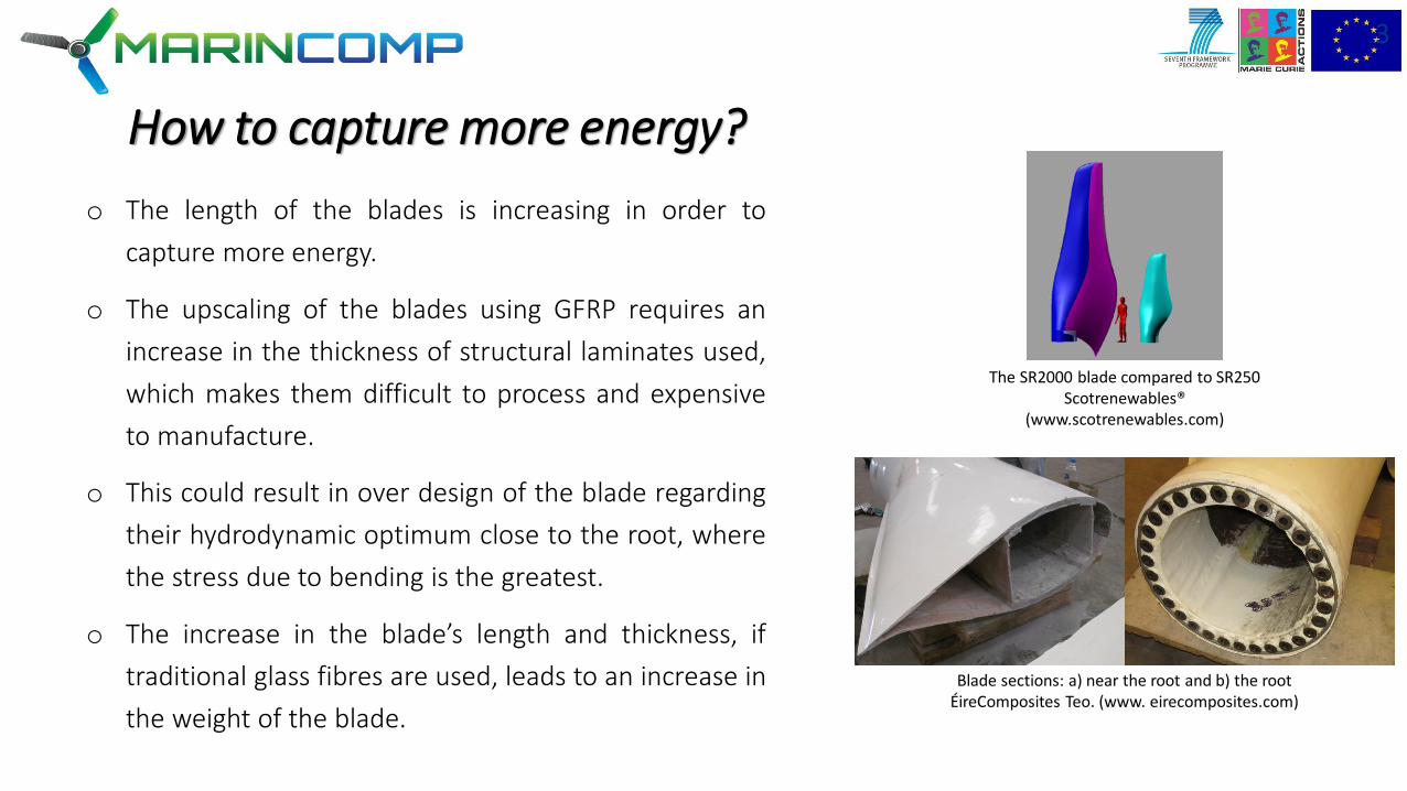
o The length of the blades is increasing in order to
capture more energy.
o The upscaling of the blades using GFRP requires an
increase in the thickness of structural laminates used,
which makes them difficult to process and expensive
to manufacture.
o This could result in over design of the blade regarding
their hydrodynamic optimum close to the root, where
the stress due to bending is the greatest.
o The increase in the blade’s length and thickness, if
traditional glass fibres are used, leads to an increase in
the weight of the blade.
How to capture more energy?
The SR2000 blade compared to SR250 Scotrenewables®
(www.scotrenewables.com)
Blade sections: a) near the root and b) the root ÉireComposites Teo. (www. eirecomposites.com)
3

Blade Design Journey
Tidal Model
Structural
Model
Initial aerodynamic design
Local blade fluid velocities
Optimum chord length
Optimum pitch angle
Axial and tangential blade forces
Hydrodynamic
ModelTidal current velocity
Strain distribution
(max. fibre strain)
Fatigue Life
Model
Fatigue life prediction
Experimental
Testing
Strain life curve
Compare
results
Design requirements
(turbine power and site
conditions)
Initial Structural Design
Strength
Basic fatigue check
Stiffness check
Weights
Natural frequency check
Optimisation of the blade
thickness
(vs. cost of electricity)
Edgewise (bending) loads check
(fatigue dependant on a blade mass)
Root design including
adhesive bond
Buckling check
Final weight
Final Element Analysis
Ultimate stress
Fatigue
Deflection
Natural frequencies
Sinusoidal model output for
water velocity.
Stream-tube model
𝐹𝐴 = 𝐿 𝑐𝑜𝑠 𝜃 + 𝐷 𝑠𝑖𝑛 𝜃The axial (thrust) force
𝐹𝐶 = 𝐿 𝑠𝑖𝑛 𝜃 + 𝐷 𝑐𝑜𝑠 𝜃The tangential (torque) force
simplified aerofoil shape used for final element (FE) analysis
FE model of the tidal turbine blade
Instron 8801
fatigue test
machine
V. Jaksic, C. M. Ó Brádaigh, C. R. Kennedy, D. M. Grogan, and S. B.
Leen, "Influence of Composite Fatigue Properties on Marine Tidal
Turbine Blade Design" in Durability of Composites in a Marine
Environment, Solid Mechanics and Its Applications Series, IN PRESS.
vol. 2,ed P. Davies and Y. Rajapakse: Springer, 2017.
V. Jaksic and F. Wallace, "Tidal Turbine Blade Design Journey &
The most powerful tidal turbine in the world, presented at the
Institute for Materials and Processes (IMP) and Institute for Energy
Systems (IES) joint Seminar, University of Edinburgh, Edinburgh, UK,
2016.
4

Blade Design Optimisation
Illustration of the composite layup when Co-Blade is run in optimization mode (Co-Blade Users Guide).
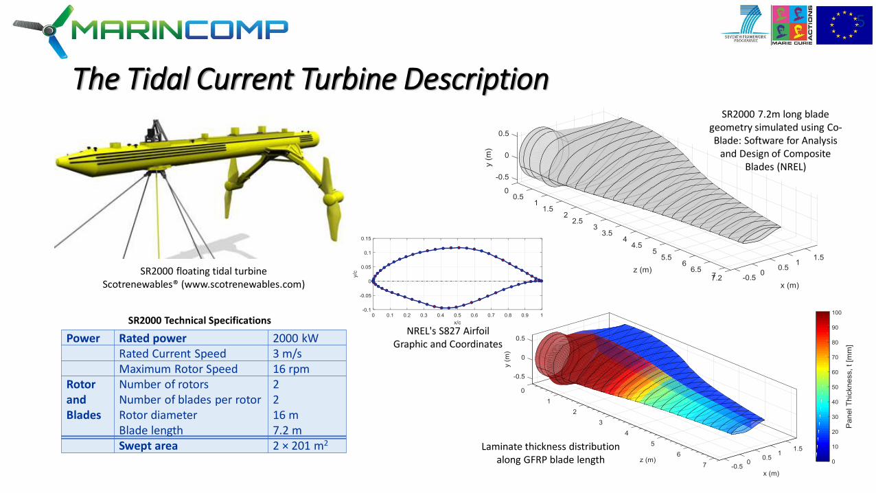
The Tidal Current Turbine Description
Power Rated power 2000 kWRated Current Speed 3 m/sMaximum Rotor Speed 16 rpm
Rotor and Blades
Number of rotorsNumber of blades per rotorRotor diameterBlade length
2216 m7.2 m
Swept area 2 × 201 m2
SR2000 floating tidal turbineScotrenewables® (www.scotrenewables.com)
5
SR2000 Technical Specifications
SR2000 7.2m long blade geometry simulated using Co-Blade: Software for Analysis
and Design of Composite Blades (NREL)
NREL's S827 AirfoilGraphic and Coordinates
Laminate thickness distribution along GFRP blade length

GFRP Tidal Blade Mass Estimation and Upscaling
6
o Tidal blades generally have large blade sections withthick structural laminates which leads to decrease ofthe blade efficiency and to the increase in the massof the blade, labour cost and total energy cost.
o “Co-Blade: Software for Structural Analysis ofComposite Blades” is used to model the blade andestimate it’s mass*. The software is based on acombination of classical lamination theory withEuler-Bernoulli theory and shear flow theory appliedto composite beams.
o A blade upscaling is shown to be proportional to theincrease of the blade length.
* D. C. Sale, "User’s Guide to Co-Blade: Software for Structural Analysis of Composite Blades,"
Northwest National Marine Renewable Energy Center, Department of Mechanical Engineering,
Seattle, US, 2012.
Mass distribution along GFRP blade length for increasing rotor diameter.
Percentage of GFRP blade mass increase with rotor diameter.

CFRP Tidal Blade Mass Estimation and Upscaling
7
Mass distribution along CFRP blade length for increasing rotor diameter.
o 14.5% Decrease in the overall blade mass distributionalong the blade in comparison with the same lengthGFRP blade
Mass distribution along optimised CFRP blade length for increasing rotor diameter.
o Co-Blade can obtain an optimal composite layup whichminimizes the blade mass while simultaneously satisfyingconstraints on maximum stress, buckling, deflection, andplacement of blade natural frequencies
Laminate thickness distribution along CFRP blade length.
o The mass of the benchmark blade is reduced by 64%,while it is approximately 62% for the GFRP blades ofthe greater length.
o The optimised CFRP blade requires an average of 56%less material in comparison to the CFRP upscaledblade

Conclusions
7
o Tidal turbine blades require thick laminates due to their small crosssection and high loading.
o A simple upscaling of the blade will only lead to an increase of theblade mass (i.e. cost), imposing additional loading on the blade root,reducing the hydrodynamic efficiency of the blade and reducing theturbine energy productivity.
o The manufacturing of the thick laminates posse the difficultyincreasing the cost of labour and production.
o The mass of the blade can be notably reduced by changing thegeometry of the spar and employing CFRP instead of GFRP in itsdesign.
o The optimisation of the blade mass can be further improved by theuse of realistic saturated material properties (avoiding the overconservative design safety factors).
The SR2000 2MW at Harland and Wolff Heavy Industries Ltd., Belfast
Scotrenewables® (www.scotrenewables.com)

8