listof experiments
TRANSCRIPT

1
LISTOF EXPERIMENTS
S. No. NAME OF EXPERIMENTS PAGE No.
FROM TO
1. To study refrigeration cyc;e, determine of coefficient of performance
of cycle & determine of tonnage capacity of refrigeration unit.
2. To determine the COP and tonnage capacity of the chilling plant.
3. To determine COP and tonnage capacity of a Air conditioning system.
4. To determine the COP and tonnage capacity of a Mechanical Heat
Pump.
5. To determine the COP and tonnage capacity of an Ice plant.
6. To study the cut sectional model of reciprocating, rotary and
centrifugal compressor.
7. To study various controls used in Refrigeration and Air-conditioning
system.
8. To study different psychrometric process & chart.
9. To study works principle of steam jet refrigeration system.
10. To study the analysis of simple vapour compression cycle and explain
the types of vapour compression cycle with T-S and P-H diagram.

2
BRCM COLLEGE OF ENGINEERING & TECHNOLOGY
BAHAL, BHIWANI Practical Experiment Instructions Sheet
Lab Manual
EXPERIMENT NO.1
RAC Lab REFRIGERATION & AIR CONDITIONING ME- 411-F
BRANCH-ME
Aim: - To study refrigeration cycle, determine of coefficient of performance of cycle
& determine of tonnage capacity of refrigeration unit.
Apparatus used: - Refrigeration test Rig consists of (Compressor (rotary), Air cooler condenser, Capillary
tube, Evaporator coil, voltmeter, current meter, voltmeter, energy meter, Thermocouple
pressure gauge, vacuum gauge, and freezer
Description of the Test Rig:- The experimental refrigeration cycle test rig consist of a compressor unit, condenser,
evaporator, cooling chamber, controlling devices and measuring instruments those are
fitted on a stand and a control panel. The apparatus is fabricated in such a way; to
refrigeration system hermetically sealed compressor is fitted on stand with the help of
flexible foundation bolts to minimize vibrations. Electric power input to the compressor is
given through thermostatic switch.
Temperature sensor details: -
1. T1 = Temperature Sensor : Fixed at Compressor Discharge Line
2. T2 = Temperature Sensor : Fixed after Condenser
3. T3 = Temperature Sensor : Fixed after Capillary Tube
4. T4 = Temperature Sensor : Inside freezer
5. T5 = Temperature Sensor: Fixed at Compressor Suction Line. Theory: -
The coefficient of performance of refrigeration plant is given by the ratio of heat absorbed,
by the refrigerant when passing through the evaporator or the system, to the working input
to the compressor to compress the refrigeration.
Co-efficient of Performance = Heat removed by refrigerant / Power input
Cop plant = m Cp ΔT / K. Wh Where

3
m = mass of water kept in cooling chamber
Cp = specific heat of water = 4.18 Kj /Kg K
ΔT = temperature of cooling water K
Kwh = 1000 x V.I x 60 x 60 KJ = V.I x KJ = V.I x 3600 KJ
KWH = reading of energy meter.
Co-efficient of refrigeration cycle is given by the ratio of net refrigeration effect to the
power required to run the compressor.
COP (cycle) Net refrigerant effect in unit time / Power input in unit time
= m CpΔT / KwH
Where (Q), = mass flow rate of the refrigerant m3
/ sec
Cp = Specific heat of refrigerant
ΔT = Temperature difference (T1-T3) KWH = Kilowatt hours energy meter reading.
The co-efficient of performance of a refrigeration system is given by the ratio of heat
absorb, to the work input.
COP = Heat removed by refrigerant / Power input
= m x CpΔT / K.Wh Where,
m = mass of water kept in cooling chamber
Cp = specific heat of water = 4.18 Kj /Kg K
ΔT = temperature of cooling water K
Kwh = power consumed by the compressor in unit time.
Tonnage capacity:
The capacity of a refrigeration machine is the refrigeration effect in a given time from a
body. This capacity of machine is given by standard commercial ton of refrigeration. This
is called as refrigerating effect i.e. melting of 1 ton of ice at 0°C in 24 hours.
TR = 336 x 1000 / 24 x 60 x 60 = 3.88 Kj / sec.
Tonnage capacity of the machine = Net refrigerating effect of machine / 3.88
= m x CpΔT / 3.88

4
Procedure: Switch on the compressor and let it run for considerable time. Say for automatic cut off by
thermostatic switch at normal position. Fill a measured quantity of water in ice cane (100
gm) and put it into cooling chamber. Measure initial temperature of water before putting
into cooling chamber by noting the value of T4 as T4i note down the energy meter reading.
Wait till compressor starts. Compressor shall be started automatically as and when
temperature of cooling chamber falls up to adjusted temperature.
After starting the compressor note down the temperature T4 at the interval of every 15
minutes and note it down as T4C.
Note down the power consumed by compressor till ice forms i.e. temperature T4 should reach O°C. At 0°C of ice cane note down all the temperature i.e. T1, T2, T3, T4 and T5.
Also note down the suction and discharge pressure by the respective gauges. Note down the
flow rate of refrigerant by rotometer.
Hence Refrigeration effect TR = 336 x 1000 / 24 x 14000 KJ / hour
Where latent heat of fusion of ice = 336 KJ / kg.
Tonnage capacity of the plant
= Net refrigerant effect of plant / 14000 KJ / hour
= m x CpΔT / 14000
Where, m = mass of water kept in cooling chamber
Cp = initial and final heat of water = 4.18
ΔT = initial temp. Tc = final temperature water T1- T2
T1 = initial temperature of water.
Tc = final temperature of water
Tonnage capacity of cycle
= Net refrigerating effect produced by refrigerant / 14000 Kj /h
= m x CpΔT / 14000 tones
Where, m = mass flow rate of refrigerant
Cp = Specific heat of refrigerant
ΔT = Temperature of refrigerant at discharge and suction = T1, T5
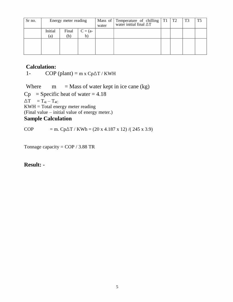
Observation Table
5
Sr no. Energy meter reading Mass of
water
Temperature of chilling water initial final ΔT
T1 T2 T3 T5
Initial
(a)
Final
(b)
C = (a-
b)
Calculation: 1- COP (plant) = m x CpΔT / KWH
Where m = Mass of water kept in ice cane (kg)
Cp = Specific heat of water = 4.18
ΔT = T4i – T4C
KWH = Total energy meter reading
(Final value – initial value of energy meter.)
Sample Calculation
COP = m. CpΔT / KWh = (20 x 4.187 x 12) /( 245 x 3.9)
Tonnage capacity = COP / 3.88 TR
Result: -

6
BRCM COLLEGE OF ENGINEERING & TECHNOLOGY
BAHAL, BHIWANI Practical Experiment Instructions Sheet
Lab Manual
EXPERIMENT NO.2
RAC Lab REFRIGERATION & AIR CONDITIONING ME- 411-F
BRANCH-ME
Aim: - To determine the COP and Tonnage capacity of the chilling plant.
Apparatus: - Compressor, Condenser, Evaporator, Capillary Tube, Ammeter, Voltmeter.
Theory: - The apparatus consist of a hermitically sealed compressor which is fitted on the base of a
stand on a wooden stand. The compressed refrigerant from the compressor flows
towards the air cooled finned condenser. After the condenser condensed refrigerant is
collected in the receiver tank and from receive it passing through a filter drier and capillary
tube and enter into evaporator (cooling coil) unit. Evaporator unit is a shell and tube type
heat exchanger, which consist of stainless steel vassal and evaporator coil is wounded in
this vassal (tank) an arrangement is provided to flow water to be chilled in this tank. Flow
rate of the chilled water is measured by using a Rota meter. Refrigerant after the evaporator
unit is sucked back in compressor. Power input to the compressor is measured by using the
energy meter which giving power consumed by compressor directly. A pressure and
vacuum range is fitted on the control panel to measure pressure at the discharge and suction
respectively. Digital temperature indicator is also fitted on control panel to measure
temperature at different positions. A selector switch is provided over these by turning its
position respective temperature may be noted.
Coefficient of Performance
The Co-efficient of performance of a chilling plant is given by the ratio of heat absorb to
the work input.
COP = Heat removed by refrigerant / Power input
= m x CpΔT / K.Wh Where,
m = mass of water kept in the evaporator unit / mass flow rate of the water.
Cp = specific heat of water = 4.18 Kj /Kg K
ΔT = temperature difference of chilling water
Kwh = power consumed by the compressor in unit time.
Tonnage capacity:- The capacity of a refrigeration machine is the refrigeration effect in a given time from a
body. This capacity of machine is given by standard commercial tone of refrigeration. This
is called as refrigerating effect i.e. melting of 1 ton of ice at 0°C in 24 hours.
TR = 336 x 1000 / 24 x 60 x 60 = 3.88 KJ / sec.

7
Tonnage capacity of the machine = Net refrigerating effect of machine / 3.88
= m x CpΔT / 3.88
Temperature sensor details: -
o T1 = Temperature Sensor : Fixed at Compressor Discharge Line
o T2 = Temperature Sensor : Fixed after Condenser
o T3 = Temperature Sensor : Fixed after Capillary Tube
o T4 = Temperature Sensor : Inside Water Cooling Tank
o T5 = Temperature Sensor : Fixed at Compressor Suction Line.
Procedure:
Switch on the compressor and let it to run for considerable time, until thermostatic switch
starts functioning. Now fill the measured quantity of the water in evaporator or allow water
to flow through the tank. Note down the reading of energy meter and initial temperature of
chilling water and start stop watch and take the readings required for calculations in the
table for certain interval.
ObservationTable
Sr no. Energy meter reading Mass of
water
Temperature of
chilling water
initial final ΔT
T1 T2 T3 T5
Initial
(a)
Final
(b)
C =
(a-b)
Sample Calculation COP
= m. CpΔT / KWh = 20 x 4.187 x (12) / 245 x 3.9
Tonnage capacity
= COP / 3.88 TR
Precautions: -
1. Keep all the hand shut off valves tight closed until not required.
2. Keep small flow rate of the chilling water.
3. Compressor should not continuously for long time that should be hermetically cut
down by the by the thermostat switch.
4. Do not disturb the copper piping, because it may cause leakage of the refrigerant
from the system.
Result: -

8
BRCM COLLEGE OF ENGINEERING & TECHNOLOGY
BAHAL, BHIWANI Practical Experiment Instructions Sheet
Lab Manual
EXPERIMENT NO.3
RAC Lab REFRIGERATION & AIR CONDITIONING ME- 411-F
BRANCH-ME
Aim: - To Determine COP and Tonnage capacity of a Air Conditioning system.
Apparatus: - Compressor, Condenser, Evaporator, Capillary Tube, Ammeter, Voltmeter.
Theory: -
Air conditioning equipment is used to maintain controlled atmospheric conditions as per
required. The controlled atmospheric conditions may be required for human comfort or
manufacturing processes of engineering goods. Air conditioning systems are classified in
two groups.
1. Packed Units
2. Central Unit
A packed unit is self-contained unit, because complete unit including compressor,
evaporator, condenser, fan motor etc. are kept in a common enclosure. Capacity of packed
or window AC is 1 to 1.5 T.R. This AC is mounted with the room which is required for
controlled atmosphere.
A window AC mainly consists of following sub-assemblies:
1. System assembly includes compressor, condenser, evaporator, expansion device, and
filter.
2. Motor with blower & fan assembly includes, a double ended shaft motor, a fan and a
motor and suitable bracket for it.
3. Cabinet and air distributing assembly – it includes a cabinet as enclosure for whole
system, an air distributing system.
4. Control panel assembly – it includes the switched those required to control the entire
AC system as per the requirement, IC temperature, humidity etc.
The AC Test Rig is designed and fabricated, to determine the performance and to study its
working principle. The AC test Rig consist a 1.5 T sealed compressor unit, a finned
condenser (heating coil) and evaporator (cooling coil), a double ended (shaft) motor to run
fan and blower simultaneously and fitted on a wooden stand and properly covered by grill.
A duct is assembled along with blower unit as a carrier of comfort air, the velocity of the
air passing through the coil is measured by using a pilot tube fitted in duct itself and
connected to V-tube manometer which is fitted on control panel. The control panel is fitted
over compressor and fan-blower assembly. Control panel consist of 1 phase energy meter
to measure power consumed by compressor, a Rota meter to measure flow rate of
refrigerant pressure gauge to measure pressure of discharge side compound vacuum gauge

9
to measure suction side pressure, a digital temperature indicator to measure temperature at
various places. The desired temperature find out by changing position of selector switch
with it. A voltmeter and ammeter is also fitted on control panel.
Specifications of AC Test Rig:
Compressor : Hermetically sealed compressor 1.5 T.R. with starting and running capacitor.
Refrigerant : R – 22
Pressure gauge : 0.300 PSI
Suction gauge : - 30-0-150 PSI
Rota meter : 0-5 L L PM
Fan blower motor : 1 / 30 HP 1- 0
Condenser & evaporator : Double row finned.
Window type air conditioner The performance of an air-conditioning system is expressed in terms of co-efficient of
performance. And COP is the ratio of net refrigerating effect and power supplied to do the
work i.e.
COP = Rn / W
Where
Rn = heat removed by system
= m. CpΔT
Where
m = mass of air supplied / minute.
Cp = Specific heat of air
ΔT = Difference in temperatures.
T1 – T2
T1 = Surrounding temperature
T2 = Air duct temperature Mass of circulated air can be calculated by
m = Va / Vsa
Where
Va = Quantity of air supplied m3 / min.
Vsa = Area of duct x velocity of the air.
= L x b x √2{P (stag) – P (stat)} / ρ ρ = mass density of air
P (stag) = Stagnation or total pressure. P
(stat) = Static pressure
W = Power input time and measured by energy meter reading.
10
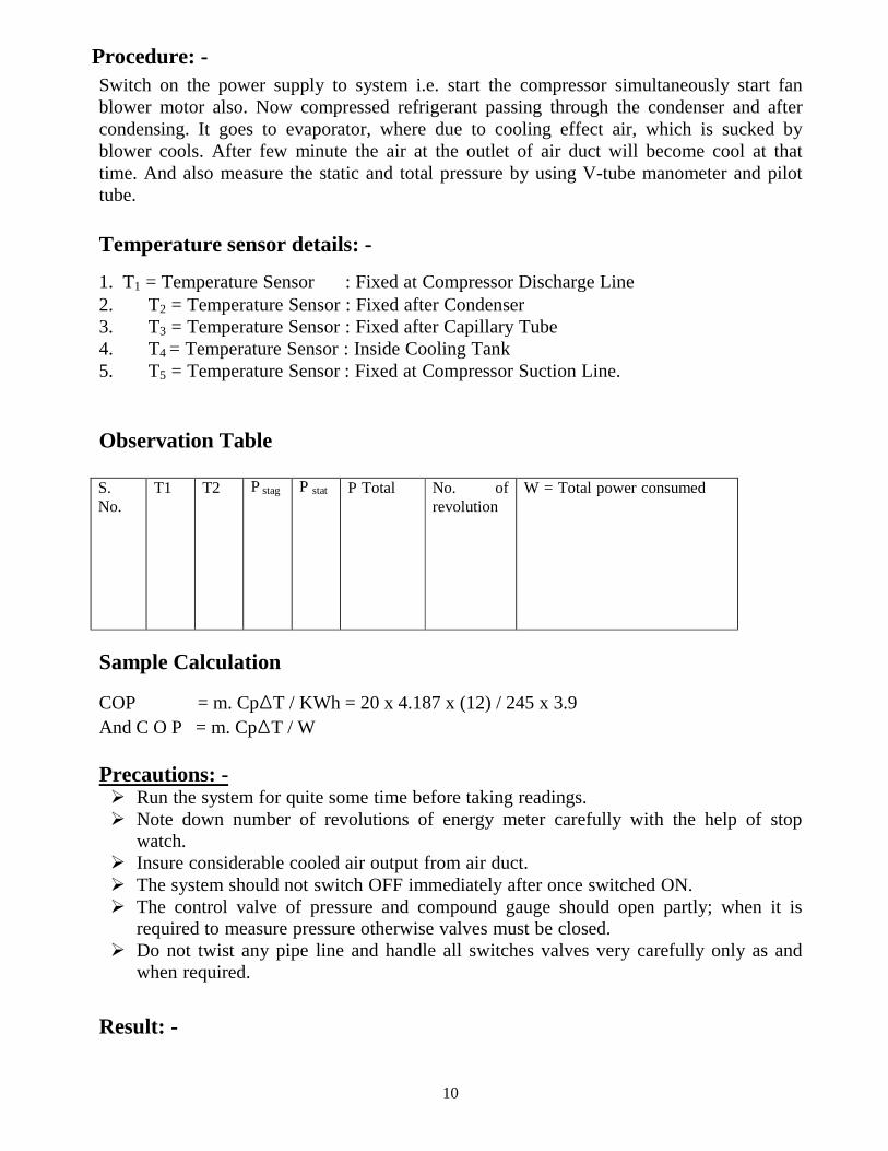
Procedure: -
Switch on the power supply to system i.e. start the compressor simultaneously start fan
blower motor also. Now compressed refrigerant passing through the condenser and after
condensing. It goes to evaporator, where due to cooling effect air, which is sucked by
blower cools. After few minute the air at the outlet of air duct will become cool at that
time. And also measure the static and total pressure by using V-tube manometer and pilot
tube.
Temperature sensor details: -
1. T1 = Temperature Sensor : Fixed at Compressor Discharge Line
2. T2 = Temperature Sensor : Fixed after Condenser
3. T3 = Temperature Sensor : Fixed after Capillary Tube
4. T4 = Temperature Sensor : Inside Cooling Tank
5. T5 = Temperature Sensor : Fixed at Compressor Suction Line.
Observation Table
S.
No.
T1 T2 P stag P stat P Total No. of
revolution
W = Total power consumed
Sample Calculation
COP = m. CpΔT / KWh = 20 x 4.187 x (12) / 245 x 3.9
And C O P = m. CpΔT / W
Precautions: - Run the system for quite some time before taking readings.
Note down number of revolutions of energy meter carefully with the help of stop
watch.
Insure considerable cooled air output from air duct.
The system should not switch OFF immediately after once switched ON.
The control valve of pressure and compound gauge should open partly; when it is
required to measure pressure otherwise valves must be closed.
Do not twist any pipe line and handle all switches valves very carefully only as and
when required.
Result: -
11
Sink(T2) Heat
Pump
BRCM COLLEGE OF ENGINEERING & TECHNOLOGY
BAHAL, BHIWANI Practical Experiment Instructions Sheet
Lab Manual
EXPERIMENT NO.4
RAC Lab REFRIGERATION & AIR CONDITIONING ME- 411-F
BRANCH-ME
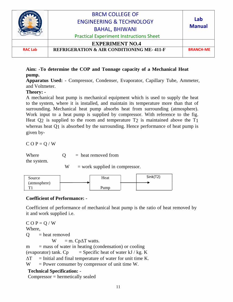
Aim: -To determine the COP and Tonnage capacity of a Mechanical Heat
pump. Apparatus Used: - Compressor, Condenser, Evaporator, Capillary Tube, Ammeter,
and Voltmeter.
Theory: - A mechanical heat pump is mechanical equipment which is used to supply the heat
to the system, where it is installed, and maintain its temperature more than that of
surrounding. Mechanical heat pump absorbs heat from surrounding (atmosphere).
Work input to a heat pump is supplied by compressor. With reference to the fig. Heat Q2 is supplied to the room and temperature T2 is maintained above the T1 whereas heat Q1 is absorbed by the surrounding. Hence performance of heat pump is
given by-
C O P = Q / W
Where Q = heat removed from
the system.
W = work supplied in compressor.
Source
(atmosphere)
T1
Coefficient of Performance: - Coefficient of performance of mechanical heat pump is the ratio of heat removed by
it and work supplied i.e. C O P = Q / W
Where,
Q = heat removed
W = m. CpΔT watts.
m = mass of water in heating (condensation) or cooling
(evaporator) tank. Cp = Specific heat of water kJ / kg. K
ΔT = Initial and final temperature of water for unit time K.
W = Power consumer by compressor of unit time W.
Technical Specification: - Compressor = hermetically sealed

12
of 1/3 T Discharge pressure gauge
= 0-3 - PSI Suction pressure gauge
= - 30-0-150 PSI
T1 & T2 are temperature of discharge suction side 0°C
T3 and T7 are temperature of water 0°C
T2, T3, T5 and T6 are temperature of inlet and outlet of heating and cooling coil.
Procedure: -
Fill measured quantity of water in condenser and evaporator banks and note down the initial temperature of tanks by means of selector switch as T4i. Now note
down the energy meter and switch on the power supply to compressor. Run the compressor for unit time (say 30 minute) and note down the change in temperature of T4f and energy meter reading. Above procedure may be repeated for cooling coil
also.
Temperature sensor details: -
1. T1 = Temperature Sensor: Fixed at Compressor Discharge Line
2. T2 = Temperature Sensor: Fixed after Condenser
3. T3 = Temperature Sensor: Inside hot water tank
4. T4 = Temperature Sensor: fixed after capillary tube
5. T5 = Temperature Sensor : Inside cold water tank
6. T6 = Temperature Sensor : Fixed at Compressor Suction Line
Observation Table
S. no. Time T3
I
T4
f
Mass of water in
condensation
Mass of water in
evaporator
Energy meter
reading
Calculation: Q = m.Cp T = ……….Watts
W=………Watts
COP = Q/W ………%. Precautions: - Use stabilized power supply.
Drain the water from tanks after performing experiment.
When apparatus is no longer in use condense the refrigerant.
Use stop watch for time measurement.
Result: -
13
BRCM COLLEGE OF ENGINEERING & TECHNOLOGY
BAHAL, BHIWANI Practical Experiment Instructions Sheet
Lab Manual
EXPERIMENT NO.5
RAC Lab REFRIGERATION & AIR CONDITIONING ME- 411-F
BRANCH-ME
Aim: - To study the Air and Water heat pump and find its C.O.P. Apparatus: - Compressor, Condenser, Evaporator, Capillary Tube, Ammeter, and
Voltmeter.
Operating principles:
Mechanical heat pumps exploit the physical properties of a volatile evaporating
and condensing fluid known as a refrigerant. The heat pump compresses the refrigerant to
make it hotter on the side to be warmed, and releases the pressure at the side where heat is
absorbed.The working fluid, in its gaseous state, is pressurized and circulated through the
system by a compressor. On the discharge side of the compressor, the now hot and highly
pressurized vapor is cooled in a heat exchanger, called a condenser, until it condenses into a
high pressure, moderate temperature liquid. The condensed refrigerant then passes through a
pressure-lowering device also called a metering device. This may be an expansion
valve, capillary tube, or possibly a work-extracting device such as a turbine. The low pressure
liquid refrigerant then enters another heat exchanger, the evaporator, in which the fluid
absorbs heat and boils. The refrigerant then returns to the compressor and the cycle is
repeated.
Theory:
Heat pump is a device that transfers heat energy from a heat source to a heat sink against a
temperature gradient. Heat pumps are designed to move thermal energy opposite the direction
of spontaneous heat flow. A heat pump uses some amount of external high-grade energy to
accomplish the desired transfer of thermal energy from heat source to heat sink.
While compressor-driven air conditioners and freezers are familiar examples of heat pumps,
the term "heat pump" is more general and applies to HVAC devices used for space heating or
space cooling. When a heat pump is used for heating, it employs the same basic refrigeration-
type cycle used by an air conditioner or a refrigerator but in the opposite direction, releasing
heat into the conditioned space rather than the surrounding environment. In this use, heat
pumps generally draw heat from the cooler external air or from the ground.
Air source heat pump (extracts heat from outside air)
Air–air heat pump (transfers heat to inside air)
Air–water heat pump (transfers heat to a heating circuit and a tank of domestic hot
water)
There are thus two types of air source heat pumps and these are commonly clearly separate
types of devices. Both devices use outside air as the heat source. Air-air heat pumps, that
extract heat from outside air and transfer this heat to inside air, are the most common type of
14
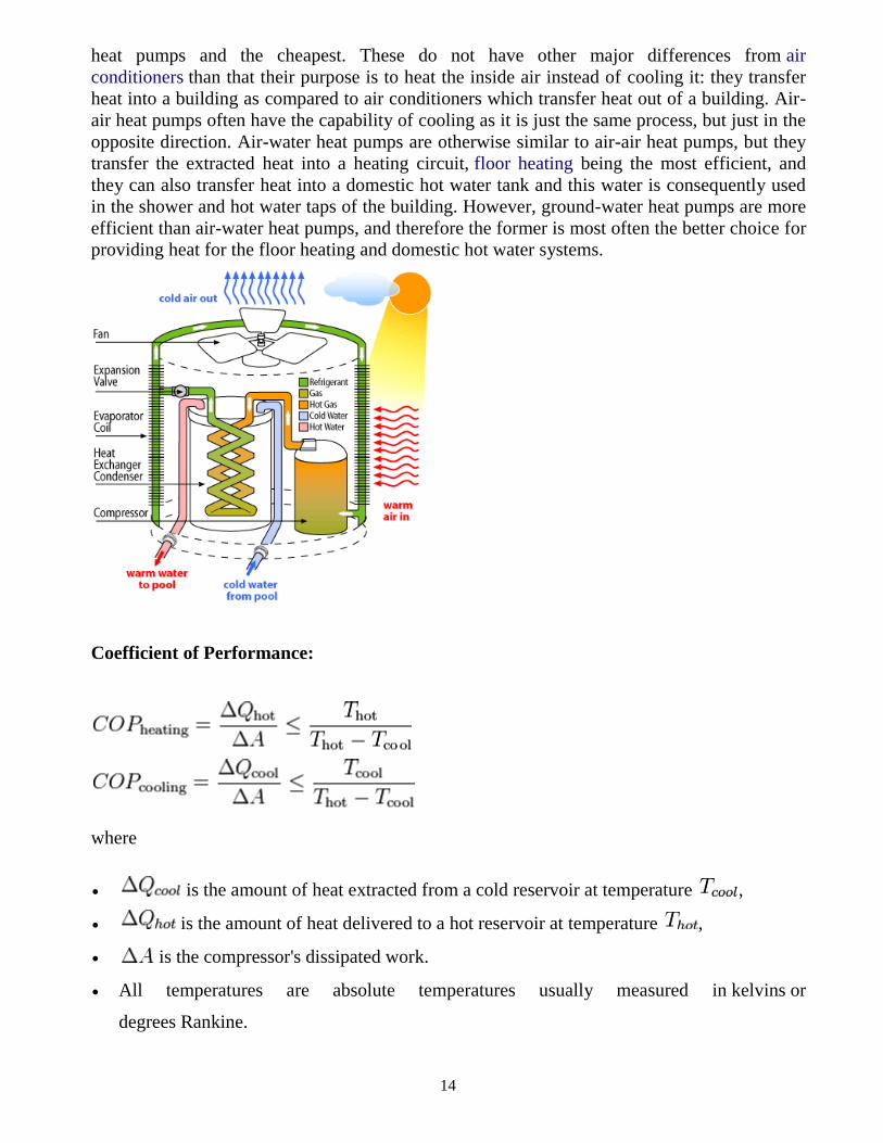
heat pumps and the cheapest. These do not have other major differences from air
conditioners than that their purpose is to heat the inside air instead of cooling it: they transfer
heat into a building as compared to air conditioners which transfer heat out of a building. Air-
air heat pumps often have the capability of cooling as it is just the same process, but just in the
opposite direction. Air-water heat pumps are otherwise similar to air-air heat pumps, but they
transfer the extracted heat into a heating circuit, floor heating being the most efficient, and
they can also transfer heat into a domestic hot water tank and this water is consequently used
in the shower and hot water taps of the building. However, ground-water heat pumps are more
efficient than air-water heat pumps, and therefore the former is most often the better choice for
providing heat for the floor heating and domestic hot water systems.
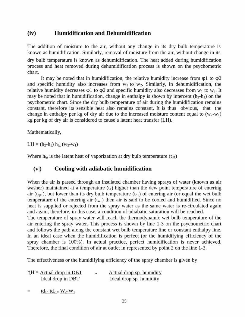
Coefficient of Performance:
where
is the amount of heat extracted from a cold reservoir at temperature ,
is the amount of heat delivered to a hot reservoir at temperature ,
is the compressor's dissipated work.
All temperatures are absolute temperatures usually measured in kelvins or
degrees Rankine.

15
BRCM COLLEGE OF ENGINEERING & TECHNOLOGY
BAHAL, BHIWANI Practical Experiment Instructions Sheet
Lab Manual
EXPERIMENT NO.5
RAC Lab REFRIGERATION & AIR CONDITIONING ME- 411-F
BRANCH-ME
Aim: - To determine the COP and Tonnage capacity of an Ice Plant.
Apparatus: - Compressor, Condenser, Evaporator, Capillary Tube, Ammeter, and
Voltmeter.
Introduction: - Ice plant machine is used to manufacture ice. Solid state of water is called the ice. Working
principle of ice plant is based on compression system. An ice plant consists of following
components.
1. Compressor: - Compressor increases the pressure and temperature of refrigerant and
pumps it out towards condenser in vapour form. After condensation that refrigerant goes to
evaporator and again converted into vapour form. From the evaporator refrigerant is sucked
by the compressor during the suction stroke and again being pump to condenser.
2. Condenser: - This is a heat exchanger and made of copper tubes of U-shape
refrigerant flows through these tubes & getting condensed by the surrounding air to forced
or natural air according to the capacity of the plant. In condenser vapour refrigerant is
converted into liquid form.
3. Receiver Tank: - This is one sort of storage tank, which is filled by the liquid
refrigerant. This tank is made of steel to withstand the high pressure and get stored. The
main advantage of receiver in only during the shut off period of plant, at which time
refrigerant can keep safe after condensation.
4. Filter driver: - To absorb moisture from the refrigerant filter drier is used. This is
made of brass and filled by silica jell or activated alumina.
5. Expansion service: - For expansion of refrigerant in evaporated expansion device are
used. There are two types of expansion devices commonly in use, (I) expansion valve, (II)
capillary tube. Capillary tube is a copper tube of very small size. Due to its small size gas is
form in is end portion which causing low temperature in evaporator.
6. Evaporator: - This is made of U-shaped tubes. In these tubes refrigerant circulated.
Evaporator is an ice plant is fitted next to expansion device. The refrigerant in evaporator
converted into vapour form and in result low temperature creating in surrounding, due to
heat transfer. Evaporator also called as cooling coil or freezing unit.

16
Theory: - The ratio of useful heat to work input is called the co-efficient of performance of a
refrigerating machine i.e.
COP = Heat output / Power input
= m. CpΔT / Kwh
Where
m = Mass of water is ice cane in kg.
Cp =Specific heat of water = 4.18
ΔT = Temperature drop of ice cane water in unit time, k
kwh = Power consumed by the compressor in unit time.
Procedure: -
Fill the water in ice box and add the solid salt in it, which that the gravity of brine
becomes
1.2. Fill the water in ice canes. The measured quantity of water should be filled. And
keep the ice canes in brine tank and close the door. Switch on the power supply to
compressor, at the time of starting note down the initial temperature of ice cane water
and energy meter reading. Also switch on the stop on the stop watch take the readings
of ice cane temperature and energy meter at the interval of 5 minutes. Take enough set of
readings for considerable difference in temperature.
Switch off the compressor and drain the ice can
water.
Observation Table:
Sr. No. Mass of water
(kg)
Temperature Energy meter Time
(sec) Initial
(a)
Final (b) ΔT
(b-a)
Initial Final
Applications:
Experimental ice plant unit consist of a hermetically sealed compressor which is fitted on
a press wood foundation and M.S stand. Discharge pipe of compressor goes to
condenser. From here refrigerant flows towards evaporator or ice tank, through the
receiver tank, drier filter and capillary tube. Condenser is of fin type and made of U-
shaped copper tubes in rows. A fan motor is fitted at stand to supply forced air to
condenser to increase heat transfer rate. Ice tank consist is a brine tank and ice cans,
those are packed in an insulation box. Refrigerant flow towards compressor from the
evaporator coil. Thermocouples are embedded on different positions. Thermocouple
number T1 at selector switch indicated the temperature of discharge side, T2 after
condensation, T3 ice can water temperature, T4 at the end of evaporator coil and T5 at
control panel is also provided which consist, energy meter, digital temperature indicator,

17
ammeter, voltmeter, pressure gauge and suction gauge. Hand shut off valves are
connected with pressure and suction gauge. By opening these valves pressure of
discharge or suction side can be checked as and when required. Density of brine is
measured with the help of hydrometer.
Calculations: -
q = Heat removed by refrigerant in unit time = m. Cp. ΔT =………
W = Power consumed by compressor in unit time = ………
COP- Q/W
Precautions: - Insure correct gravity of the brine solution
• Measure time precisely
• Store the refrigerant in receiver tank
• Drain water from ice canes
• Do not open the door of ice box
• Keep thermocouple well in deep in ice cane
Results:--

18
BRCM COLLEGE OF ENGINEERING & TECHNOLOGY
BAHAL, BHIWANI Practical Experiment Instructions Sheet
Lab Manual
EXPERIMENT NO.6
RAC Lab REFRIGERATION & AIR CONDITIONING ME- 411-F
BRANCH-ME
Aim: - To study the cut sectional model of reciprocating, rotary and centrifugal
compressor.
Apparatus u s e d : - C u t s e c t i o n a l M o d e l o f R e c i p r o c a t i n g ,
C e n t r i f u g a l a n d R o t a r y compressor
• Reciprocating compressor:
Theory: -
The compressors in which the vapour refrigerant is compressed by reciprocating motion of the piston are called reciprocating compressors. These compressors are used for refrigerant
which have comparatively low volume per Kg and a large differential press. Such as NH3
(R-717), R-12, R-22 and CH3Cl (R-40). The reciprocating compressors are available in
sizes as small as ½ KW which are used in small domestic refrigeration and up to about 150 KW for large capacity.
The two types of reciprocating compressor in general are: -
• Single acting vertical compressor.
• Double acting horizontal compressor.
The single acting compressors usually have their cylinder arranged vertically radially or in
‘V’ or ‘W’ form. The double acting compressors usually have their cylinder arranged
horizontal.
Working: -
When the piston moves downwards, the refrigerant left in the clearance space expands.
Thus, the volume of the cylinder increase and the pressure inside the cylinder decreases.
When the pressure become slightly less than the valve gets opened and the vapour
refrigerant flows into the cylinder. This flow continuous until the piston reaches the bottom
of the stroke. At bottom of the stroke, the suction valve closes because of spring action.
Now, when the piston moves upwards, the volume of the piston moves upwards, the
volume of the cylinder decreases and the pressure inside the cylinder increases. When the
pressure inside the cylinder becomes greater than that on the top of the discharge valve, the
discharge valve gets opened & the vapour refrigerant is discharged into the condenser and
the cycle is repeated.
1. Work done during isothermal compression: -

19
Work done during suction stroke: - W1 = Area A B B’ A’ = p1v1
Work done during Compression: - W2 = Area B C1 C1’ B’ = p1v1 loge (v1 / v2)
Work done during Discharge: - = 2.3 m RT1 log r
2. Work done during polytropic compression: - (p v n
= Constant)
Work done during suction stroke: - W1 = Area A B B’ A’ = p1v1
Work done during Compression: - W2 = Area BCC’ B’ = p2v2-p1v1/n - 1 Work done during Discharge: - W2 = Area CDA’C = p2v2
3. Work done during Isentropic Compression: -
W = y / y-1 x m cp (y-1 / y) (T2-T1) = m cp (T1-T2)
• Rotary compressor
Theory: - In rotary compressor, the vapour refrigerant from the evaporator is compressed
due to movement of blades. The rotary compressors are positive displacement type
compressor. Since, the clearance in rotary compressors is negligible; therefore, they have
high η vol. These may be used for refrigerants like R-12, R-22, and R-144 &
NH3.
The two types of rotary compressors are: -
• Single stationary blade
type
• Rotating blade
type
Working:
-
Single stationary blade type
It consists of a stationary cylinder, a roller and a shaft. The shaft has an eccentric on
which the roller is mounted. A blade is set into the slot of a cylinder in such a manner that
it always maintains contacts with a sloter by means of a spring. The blade moves in and out
of the slot to follow the rotor when it rotates. Since the blade separates the suction and
discharge parts, therefore it is often called a sealing blade. When the shaft rotates, the roller
also rotates the roller rotates so that it always touches the cylinder wall.

20
Rotating Blade type
It consists of a cylinder and a slotted rotor containing a number of blades. The centre
of the rotor is eccentric with the centre of the cylinder. The blades are forced against the
cylinder wall by the centrifugal action during the rotation of the motor.
The low pressure and temperature vapour refrigerant from the evaporator is
drawn through the suction port. As the rotor turns, the suction vapour refrigerant entrapped
between the two adjacent blades is compressed. The compressed refrigerant at high
pressure and temp is discharged through the discharge port to the condenser.
Centrifugal Compressor
The centrifugal compressor increases the pressure of low pressure vapour refrigerant to a
high pressure by centrifugal force. The centrifugal compressor is generally used for
refrigerants that require large displacement and low condensing pressure, such as R-12 is
and R-113. However, the refrigerant R-12 is also employed for large capacity applications
and low-temperature applications.
Theory:-
A single stage centrifugal compressor, in its simplest form, consists of an impeller to which
a number of curved vanes are fitted symmetrically. The impeller rotates in an air volute
casing with inlet and outlet points.
The impeller draws in low pressure vapour refrigerant from the evaporator. When
the impeller rotates, it pushes the vapour refrigerant from the centre of the impeller to its
periphery by centrifugal force. The high speed of the impeller leaves the vapour refrigerant
at a high velocity at the vane tips of the impeller. The kinetic energy thus attained at the
impeller outlet is converted into pressure energy when the high velocity vapour refrigerant
passes over the diffuser. The diffuser is normally a vane less type as it permits more
efficient part load operation which is quite and it further converts the kinetic energy into
pressure energy before it leves the refrigerant to the evaporator.
Viva Questions
1. What is the effect of clearance volume in reciprocating compressor?
2. Draw ideal and actual P-V diagrams for a reciprocating compressor?
3. On what factors does the volumetric efficiency of a compressor depend?
4. What is the effect of compression index and the discharge pressure on volumetric efficiency?
5. What is a multi-stage compressor? Give its advantages.
6. What do you understand by hermetic sealed compressor? Give its advantages.

21
BRCM COLLEGE OF ENGINEERING & TECHNOLOGY
BAHAL, BHIWANI Practical Experiment Instructions Sheet
Lab Manual
EXPERIMENT NO.7
RAC Lab REFRIGERATION & AIR CONDITIONING ME- 411-F
BRANCH-ME
Aim: - To study the various controls used in Refrigeration and Air conditioning
system.
Apparatus used: - Schematic diagrams of Refrigeration and Air Conditioning controls.
Theory: -
The controls are very essential for satisfactory and economical working of a refrigerant.
The electrical connection diagram of a domestic refrigerator is shown in fig. The
refrigerant is fitted with following controls.
1. Starting Relay: -
The starting relay is used to provide the necessary starting torque required to start the
motor. It also disconnects the starting winding of the motor when the motor speed
increases. When the compressor motor is to be started, the thermostat is in closed position.
When the electric supply is given, an electric current passes through the running winding of
the motor and the starting relay. Due to the flow of electric current through relay coil & due
to electromagnetism, its armature is pulled thereby closing the starting winding contacts.
The current through starting winding provides the starting torque and the motor starts. As,
the motor speed increase, the running winding current decrease. The current in the starting
relay is no longer able to hold the relay and it gets released thereby opening the starting
winding contacts. Thus, the starting winding gets disconnected.
2. Overload protector : -
The basic function is to protect the compressor motor winding from damage due to
excessive current, in the event of overloading or due to some fault in the electric circuit. It
consists of a bimetallic strip. During the normal working of the compressor, the contacts
are closed. Whenever there is any abnormal behavior, the bimetallic strip gets heated and
bands, thereby opening the motor contacts, and de-energizing it. The overload protector is
fitted on the body of the compressor and operates due to the combined action of heat
produced when current passes through the bimetallic strip and a heater element, and heat
transferred from the compressor body. It may be noted that the abnormal behavior of
compressor may be due to low voltage, high voltage, high load, low suction pressure, high
suction & discharge pressure.

22
3. Thermostat: -
A thermostat is used to control the temperature in the refrigeration. The bulb of the
thermostat is clamped to the evaporator or Freezer. The thermostat bulb is charged with
few drops of refrigerant. The thermostat can be set to maintain different temperature at a
time. When the desired temperature is obtained, the bulb of the thermostat senses it; the
liquid in it compresses and operates the bellows of the thermostat and open compressor
motor contacts. The temperature at which motor stops is called cut-out temperature. When
the temperature increases, the liquid in the bulb expands thereby closing the bellow contact
of the compressor motor. The temperature, at which compressor motor starts, is called cut-
in temperature. A thermostat is very crucial in operation of refrigerator as the running time
of compressor is reduced considerably thereby cutting the operation cost as well as
enhancing the compressor life due to non-continuous working.
Viva Questions: -
1. Describe the functioning of various controls in a refrigerator?
2. What is Thermostat?
3. What is over load protector?
4. What is starting relay?
5. What is the Function of over load protector?

23
BRCM COLLEGE OF ENGINEERING & TECHNOLOGY
BAHAL, BHIWANI Practical Experiment Instructions Sheet
Lab Manual
EXPERIMENT NO.8
RAC Lab REFRIGERATION & AIR CONDITIONING ME- 411-F
BRANCH-ME
Aim: - To study different psychrometric process & chart.
Apparatus Used: - Psychometric Process chart.
Theory: - The psychometric is a branch of Engineering Sciences which, deals with the
study of moister mixed with water vapour or humidity.
The various psychometric processes involved in air conditioning to vary the
psychometric properties of air according to the requirement are as follows:
(i) Sensible Heating
–
The heating of air, without any change is its specific humidity is known as sensible heating.
Let air at temperature td1 passes over a heating coil of temperature td3. It may be noted that
the temperature of air leaving the heating coil (td2) will be less that td3. The process of
sensible heating on psychometric chart is shown by horizontal line 1-2, extending left to right. The point 3 represents the surface temperature of the heating coil.
The heat absorbed by the air during sensible heating may be obtained from the psychometric chart by the enthalpy difference (h2 - h1). It may be noted that the
specific humidity during the sensible heating remains constant (W1-W2). The dry bulb
temperature increases from td1 to td2 and relative humidity reduces from φ1 to φ2 and
relative humidity reduces from φ1 to φ2. The amount of heat added during sensible heating may also be obtained from the relation.
Heat added: q = h2-
h1
= Cpa (td2 - td1) + W Cps (td2-td1)
= (Cpa + W Cps (td2 - td1) = (td2-td1)
Q = 1.022 (td2-td1) kJ/kg
(ii)
Sensible cooling –
The cooling of air without any change in its specific humidity is known sensible cooling.
Let air at temperature td1 passes over a cooling coil of temperature td3 as shown.
1. It may be noted that the temperature of air leaving the cooling coil (td2) will be
more

24
than td3. The process of sensible cooling is shown by horizontal line 1-2 extending
from right to left. The point 3 represents the surface temperature of the cooling coil. The heat
rejected by air during sensible cooling may be obtained from the psychometric chart by the
enthalpy difference (h1- h2). It may be noted that the specific humidity during the sensible
cooling remains constant. The dry bulb temperature reduces from td1 to td2 and relative
humidity increases from φ1 to φ2. The amount of heat rejected during sensible cooling may also be obtained from the relation.
Heat rejected q = h1-h2
= Cpa (td1-td2) =W Cps (td1 – td2)
= (Cpa+ W Cps) (td1-td2) = Cpm (td1 – td2) The term (Cpa+ W Cps) is called humid specific heat Cpm and its value is taken as 1.022 kJ /
kg K.
∴ Heat rejection, q = 1.022 (td2-td1) kJ / kg.
(iii) By pass factor of heating and cooling coil:
Let one kg of air at temperature td1 is passed over the coil having its temperature (i. e. coil
surface temperature) td3. A little consideration will show that when air passes over a coil,
some of it (say x kg) just by-passes unaffected while the remaining (1-x) kg comes in direct contact with the coil. This by-pass process of air is measured in terms of a by-pass factor. The amount of air that by-passes or the by-pass factor depends upon the following factors:
■ The no. of fins provided is a unit length i.e., pitch of cooling coil fins.
■ The no. of row in a coil in the direction of flow; and
■ Velocity of flow of air.
It may be noted that the by-pass factor of a cooling coil decreases with decrease in fin
spacing and increase in number of rows.
Balancing the enthalpies; we get:
x Cpm td1+ (1-x) Cpm td3
= 1 x Cpm td2
x (td3 - td1) = td3 - td2
x = (td3 - td2) / (td3-td1)
Where x is called the by-pass factor of the coil and is generally written as BPF. Therefore,
by-pass factor for heating coil,
BPF = (td3 - td2) / (td3-td1)
Similarly, by-pass factor for cooling coil,
BPF = (td2 - td3 ) / (td1-td3 )
25
Actual drop in DBT
= Actual drop sp. humidit
Ideal drop in DBT Ideal drop sp. humidity
(iv) Humidification and Dehumidification
The addition of moisture to the air, without any change in its dry bulb temperature is
known as humidification. Similarly, removal of moisture from the air, without change in its
dry bulb temperature is known as dehumidification. The heat added during humidification
process and heat removed during dehumidification process is shown on the psychometric
chart.
It may be noted that in humidification, the relative humidity increase from φ1 to φ2 and specific humidity also increases from w1 to w2. Similarly, in dehumidification, the
relative humidity decreases φ1 to φ2 and specific humidity also decreases from w1 to w2. It
may be noted that in humidification, change in enthalpy is shown by intercept (h2-h1) on the
psychometric chart. Since the dry bulb temperature of air during the humidification remains constant, therefore its sensible heat also remains constant. It is thus obvious, that the change in enthalpy per kg of dry air due to the increased moisture content equal to (w2-w1)
kg per kg of dry air is considered to cause a latent heat transfer (LH).
Mathematically,
LH = (h2-h1) hfg (w2-w1)
Where hfg is the latent heat of vaporization at dry bulb temperature (td1)
(v|) Cooling with adiabatic humidification
When the air is passed through an insulated chamber having sprays of water (known as air washer) maintained at a temperature (t1) higher than the dew point temperature of entering
air (tdp1), but lower than its dry bulb temperature (td1) of entering air (or equal the wet bulb
temperature of the entering air (tw1) then air is said to be cooled and humidified. Since no
heat is supplied or rejected from the spray water as the same water is re-circulated again and again, therefore, in this case, a condition of adiabatic saturation will be reached.
The temperature of spray water will reach the thermodynamic wet bulb temperature of the
air entering the spray water. This process is shown by line 1-3 on the psychometric chart
and follows the path along the constant wet bulb temperature line or constant enthalpy line.
In an ideal case when the humidification is perfect (or the humidifying efficiency of the
spray chamber is 100%). In actual practice, perfect humidification is never achieved.
Therefore, the final condition of air at outlet in represented by point 2 on the line 1-3.
The effectiveness or the humidifying efficiency of the spray chamber is given by
ηH = y
= td1- td2 = W2-W1

26
td1- td3 W3-W1
(vi) Cooling and humidification by water injection
(Evaporative cooling)
Let water at a temperature t1 is injected into the flowing steam of dry air (a). The final
condition of air depends upon the amount of water evaporation. When the water is injected at a temperature equal to the wet bulb temperature of the entering air (tw1), then the process
follows the path of constant wet bulb temperature line.
Let,
Mw = Mass of water supplied,
ma = Mass of dry air,
W1 = Specific humidity of entering air, W2 = Specific humidity of leaving air, and
Hw = Enthalpy of water injected into the air. Now for the mass balance,
W2 = W1+ mw / ma
And by heat balance,
h2 = h1+ mw / ma x hfw
= h1+ (W2 - W1) hfw.
Since (W2-W1) hfw is very small as compared to h1 and h2, therefore it may be neglected. Thus the water injection process is a constant enthalpy process, irrespective of the
temperature of water injected (i.e. whether the temperature t1< tw or t1 > tw ).
(vii) Heating and humidification
This process is generally used in winter air conditioning to warm and humidify the air. It is
the reverse process of cooling & humidity. When air is passed through a humidifier having
spray water temperature higher than the dry bulb temperature of the entering air, the
unsaturated air will reach the condition of saturation and thus the air becomes hot. The heat
of vaporization of water is absorbed from the spray water itself and hence it gets cooled. In
this way, the air becomes heated and humidified. The process of heating and humidification
is shown by line 1-2 on the psychometric chart. The air enters at condition 1 and leaves at
condition 2. In this process, the dry bulb temperature as well as specific humidity of air
increases. The final relative humidity of the air can be lower or higher than that of the
entering air.
27
Let,
mw1 and mw2 = Mass of spray water entering and leaving the humidifier in kg,
hfw1 and hfw2= Enthalpy of spray water entering and leaving the humidifier in kJ / kg.
W1 and W2 = Specific humidity of the entering and leaving air in kg / kg of dry air,
h1 and h2 = Enthalpy of entering and leaving air in kJ / kg of dry air, and
ma = Mass of dry air entering in kg.
For mass balance of spray water,
(mw1 - mw2) = ma (W2 - W1)
mw2 = mw1 - ma (W2 - W1)
For Enthalpy balance,
mw1 hfw1 - mw2 hfw2 = ma (h2-h1)
Substituting the value of mw2 from equation (i), we have
mw1 hfw1-{mw1-ma (W2 - W1)} hfw2
= ma (h2-h1)
∴ h2 - h1 = mw1 / ma(hfw1- hfw2) + (W2 - W1) hfw2
The temperatures ts1 and ts2 denote the temperatures of entering and leaving spray water respectively. The temperature t3 is the mean temperature of the spray water which the entering air may be assumed to approach.
Actually, the heating and humidification process follows the path as shown by dotted
curve, but for the calculation of psychometric properties, only the end points are important.
Thus, the heating and humidification process shown by a line 1-2 on the psychometric chart
may be assumed to have followed the path 1- A and A – 2. We see that the total heat added
to the air during heating and humidification is,
Total heat added to the air during heating humidification:
q = h2-h1= (h2-ha) + (ha- h1) = qi + qs
(viii) Heating and humidification by steam injection
The stream is normally injected into the air in order to increase its specific humidity. This

28
process is used for the air conditioning of textile industries where high humidity is
maintained. The dry bulb temperature of air changes very little during the process.
Let
ms = Mass of steam supplied,
ma = Mass of dry air entering,
W1 = Specific humidity of air entering,
W2 = Specific humidity of air leaving,
h1 = Enthalpy of air entering,
h2 = Enthalpy of air leaving, and
hs = Enthalpy of steam injected into the air. Now for mass balance;
W2 = W1+ ms / ma
For heat balance;
h2 = h1+ ms / ma x hs = h1 + (W2 - W1) hs
(ix) Adiabatic Mixing of Two Air Streams When two quantities of air having different enthalpies and different specific
humidity are mixed, the final condition of the air mixture depends upon the
masses involved, and on the enthalpy and specific humidity of each of the
constituent masses which enter the mixture.
Let m1 = Mass of air entering at 1,
h1 = Enthalpy of air entering at 1,
W1 = Specific humidity of air entering at 1,
m2, h2, W2 = Corresponding values of air entering at 2 and
m3, h3, W3 = Corresponding values of mixture leaving at 3. Assuming no loss of enthalpy and specific humidity during the air mixing process, we have
for the mass balance,
m1 + m2 = m3
For the energy balance,
m1 h1 + m2 h2 = m3 h3
and for the mass balance of water vapour,
m1 W1 + m2 W2 = m3 W3
Substituting the value of m3 from equation (i) in equation (ii),
29
m1 h1 + m2 h2 = (m1 + m2) h3 = m1 h3 + m2 h3
or m1 h1 – m1 h3 = m2 h3 – m2 h2
m1 (h1 – h3) = m2 (h3 – h2)
∴ m1 / m2 = h3 – h2 / h1 – h3
Similarly, substituting the value of m3 from equation (i) in equation (iii), we have
m1 / m2 = W3 - W2 / W1 - W3
Now from equation (iv) and (v),
m1 / m2 = h3 – h2 / h1 – h3 = W3-W2 / W1-W3
The adiabatic mixing process is represented on the psychometric chart as shown in fig. The
final condition of the mixture (point 3) lies on the straight line 1-2. The point 3 divides the
line1-2 in the inverse ratio of the mixing masses. By calculating the value of W3 from
equation (vi), the point 3 is plotted on the line 1-2.
It may be noted that when warm high humidity air is mixed with cold air, the
resulting mixture will be a fog and the final condition (point 3) on the psychometric chart
will lie to the left or above the saturation curve which represents the fog region. The
temperature of the fog is that of the extended wet bulb line passing through point 3.
The fog may also result when steam or a very fine water spray is in injected into air
in a greater quantity that required saturate the air. Even lesser quantity of steam, if not
mixed properly, may result fog.
The fog can be cleared by heating the fog, mixing the fog with warmer unsaturated
air or mechanically separating the water droplets from the air.
Viva Questions 1. What do you understand by the term ‘psychometric’?
2. Define Specific humidity?
3. Define Absolute humidity?
4. What is Relative humidity?
5. What is Dew point temperature?
6. What is a sling psycho- meter?
7. What is by-pass factor for cooling coils?
8. Define sensible heat factor?
9. What is fog?

30
BRCM COLLEGE OF ENGINEERING & TECHNOLOGY
BAHAL, BHIWANI Practical Experiment Instructions Sheet
Lab Manual
EXPERIMENT NO.9
RAC Lab REFRIGERATION & AIR CONDITIONING ME- 411-F
BRANCH-ME
Aim: - To Study working principle of steam jet refrigeration system.
Apparatus Used: - Reference of steam jet refrigeration system diagram and P -H
and T - S diagrams.
Theory: - The steam jet refrigeration system (also known as ejector system refrigeration system) is
one of the oldest methods of producing refrigeration effect. The basic components of this
system are an evaporator, a compressor device, a condenser and a refrigerant control
device. This system employs a steam injector or booster (instead of mechanical
compressor) to compress the refrigerant to the required condenser pressure level. In this
system, water is used as the refrigerant. Since the freezing point of water is 0°C, therefore,
it cannot be used for applications below 0°C. The steam jet refrigeration system is widely
used in food processing plants for pre-cooling of vegetables and concentrating fruit juices,
gas plants, paper mills, breweries etc.
Principle of steam jet refrigeration system: -
The boiling point of a liquid changes with change in external pressure. In normal
conditions, pressure exerted on the surface of a liquid is the atmospheric pressure. If this
atmospheric pressure is reduced on the surface of a liquid, by some means, then the liquid
will start boiling at lower temperature, because of reduced pressure. This basic principal of
boiling of liquid at lower temperature by reducing the pressure on its surface is used in
steam jet refrigeration system.
The boiling point of pure water at standard atmospheric pressure of 760 mm of Hg is 100°C. It may be noted that water boils at 12°C if the pressure on the surface of water is kept at 0.014 bar and at 7°C if the pressure on the surface of water is 0.01 bar. The reduced
pressure on the surface of water is maintained by throttling the steam through the jets or
nozzles.
Working of steam jet refrigeration system: -
The flash chamber or evaporator is a large vessel and is heavily insulated to avoid the rise
in temperature of water due to high ambient temp. It is fitted with perforated pipes for
spraying water. The warm water coming out of the refrigerated space is sprayed into the
flash water chamber where some of which is converted into vapours after absorbing the
latent heat, thereby cooling the rest of water.

31
The high pressure steam from the boiler is passed through the steam nozzle thereby
increase its velocity. The high velocity steam in the ejector would entrain the water vapours
from the flash chamber which would result in further information of vapour. The mixture
of steam and water vapour passes through the ventilate-tube of the ejector and gets
compressed. The temperature and pressure rises considerably and fed to the water cooled
condenser where it gets condensed. The condensate is again fed to the boiler as feed water.
A constant water level is maintained in the flash chamber and any loss of water due to
evaporation is made up from the make-up water line.
Steam Ejector: -
The steam ejector is one of the important components of a steam jet refrigeration system. It
is used to compress the water vapours coming out of the flash chamber. It uses the energy
of fast moving jet of steam to entrain the vapours from the flash chamber and then compress
it. The high pressure steam from the boiler expands while flowing through the convergent
divergent nozzle. The expansion causes a very low pressure and increases steam velocity.
The steam attains very high velocities in the range of 1000 m/s to 1350 m/s. The nozzles are
designed for lowest operating pressure ratio between nozzle throat and exit. The nozzle
pressure ratio of less than 200 is undesirable because of poor ejector efficiency when
operating at low steam pressure.
The water vapour from the flash chamber are entrained by the high velocity steam and both
are mixed in the mixing section at constant pressure. The mean velocity of the mixture will
be supersonic, after the mixing is complete. This supersonic steam gets a normal shock, in
the constant area throat of the diffuser. This results in the rise of pressure and subsonic
flow. The function of the diverging portion of the diffuser is to recover the velocity head as
pressure head by gradually reducing the velocity.
Analysis of Steam Jet Refrigeration System: -
The temperature – entropy (T– s) and enthalpy-entropy (h - s) diagrams for a steam jet
refrigeration system are shown in fig. (a) and (b) respectively.
The point A represents the initial condition of the motive steam before passing through the
nozzle and the point B is the final condition of the steam, assuming isentropic expansion.
The point C represents the initial condition of the water vapour in the flash chamber or
evaporator and the point E is the condition of the mixture of high velocity steam from the
nozzle and the entrained water vapour before compression. Assuming isentropic
compression, the final condition of the mixture discharged to the condenser is represented
by point F. The final condition of the before mixing with the water vapour is shown at
point D. The make-up water is supplied at point G whose temperature is slightly lower than
the condenser temperature and is throttled to point H in the flash chamber.
Viva Questions 1. What is principle of a steam jet refrigeration system?
2. Explain the working of steam jet refrigeration system?
3. What are the advantages of steam jet refrigeration system?
4. What are the disadvantages of steam jet refrigeration system?
5. What is Steam Ejector?
32
BRCM COLLEGE OF ENGINEERING & TECHNOLOGY
BAHAL, BHIWANI Practical Experiment Instructions Sheet
Lab Manual
EXPERIMENT NO.10
RAC Lab REFRIGERATION & AIR CONDITIONING ME- 411-F
BRANCH-ME
Aim: - To study the analysis of simple vapour compression cycle and explain the
various types of Vapour compression cycle with T-S and P-H diagram
Apparatus Used: - schematic diagram of Simple vapour compression cycle.
Theory: A vapour compression refrigeration system is an improved type of air refrigeration system
in which a suitable working substance, termed as refrigerant, is used. It condenses and
evaporates at temperatures and pressures close to the atmospheric conditions. The
refrigerants, usually, used for this purpose are ammonia (NH3), carbon dioxide (CO2) and
sulphur dioxide (SO2). The refrigerant used, does not leave the system, but is circulated
throughout the system alternately condensing and evaporating. In evaporating, the
refrigerant absorbs its latent heat from the brine (salt water) which is used for circulating it
around the cold chamber. While condensing, it gives out its latent heat to the circulating
water of the cooler. The vapour compression refrigeration system is, therefore a latent heat
pump, as it pumps its latent heat from the brine and delivers it to the cooler. The vapour
compression refrigeration system is now-a-days used for all purpose refrigeration. It is
generally used for all industrial purpose from a small domestic refrigerator to a big air
conditioning plant.
Mechanism of a Simple Vapour Compression Refrigeration System
Compressor:
The low pressure and temperature vapour refrigerant from evaporator is drawn into the
compressor through the inlet or suction valve A, where it is compressed to a high pressure
and temperature. This high pressure and temperature vapour refrigerant is discharged into
the condenser through the delivery or discharge valve B.
Condenser:
The condenser or cooler consists of coils of pipe in which the high pressure and
temperature vapour refrigerant is cooled and condensed. The refrigerant, while passing
through the condenser, gives up its latent heat to the surrounding condensing medium
which is normally air or water.

33
Receiver:
The condensed liquid refrigerant from the condenser is stored in a vessel known as
receiver from where it is supplied to the evaporator through the expansion valve or
refrigerant control valve.
Expansion valve:
It is also called throttle valve or refrigerant control valve. The function of the expansion
valve is to allow the liquid refrigerant under high pressure and temperature to pass at a
controlled rate after reducing its pressure and temperature. Some of the liquid refrigerant
evaporates as it passes through the expansion valve, but the greater portion is vaporized in
the evaporator at the low pressure and temperature.
Evaporator:
An evaporator consists of coils of pipe in which the liquid-vapour refrigerant at low
pressure and temperature is evaporated and changed into vapour refrigerant under high
pressure and temperature to pass at a controlled rate after reducing its pressure and
temperature. Some of the liquid refrigerant evaporates as it passes through the expansion
valve, but the greater portion is vaporized in the evaporator at the low pressure and
temperature.
Types of Vapour Compression Cycles:
We have already discussed that vapour compression cycle essentially consists of
compression, condensation, throttling and evaporation. Many scientists have focused their
attention to increase the coefficient of performance of the cycle. Though there are many
cycles, yet the following are important from the subject point of view:
1. Cycle with dry saturated vapour after compression,
2. Cycle with wet vapour after compression,
3. Cycle with superheated vapour after compression,
4. Cycle with superheated vapour before compression, and
5. Cycle with under-cooling or sub-cooling of refrigerant.
Theoretical Vapour Compression Cycle with Dry Saturated Vapour after
compression
A vapour compression cycle with dry saturated vapour after compression is shown
on T-S and P-H diagrams in (a) and (b) respectively. At point 1, let T1, p1 and s1, be the
temperature, pressure and entropy of the vapour refrigerant respectively. The four
processes of the cycle are as follows:
34
1. Compression Process:
The vapour refrigerant at low pressure p1 and temperature T1 is compressed isentropic ally
to dry saturated vapour as shown by the vertical line 1-2 on T-s diagram and by the curve 1-2 p - h diagram. The pressure and temperature rises from p1 to p2 and T1 to T2
respectively.
w = h2-h1
Where
h1 = Enthalpy of vapour refrigerant at temperature T1, i.e. at suction of the compressor, and
h2 = Enthalpy of the vapour refrigerant at temperature T2, i.e. at discharge of the
compressor.
2. Condensing process:
The high pressure and temperature vapour refrigerant from the compressor is passed
through the condenser where it is completely condensed at constant pressure p2 and
temperature T2, as shown by the horizontal line 2-3 on T-s and p-h diagrams. The vapour
refrigerant is changed into liquid refrigerant. The refrigerant while passing through the condenser, gives its latent heat to the surrounding condensing medium.
3. Expansion process
The liquid refrigerant at pressure p3 = p2 and temperature T3 = T2 is expanded by throttling
process through the expansion valve to a low pressure p4 = p1 and temperature T4 = T1 as
shown by the curve 3-4 on T-s diagram and by the vertical line 3-4 on p-h diagram. We
have already discussed that some of the liquid refrigerant evaporates as it passes through the expansion valve, but the greater portion is vaporized in the evaporator. We know that
during the throttling process, no heat is absorbed or rejected by the liquid refrigerant.
4. Vaporizing process:
The liquid-vapour mixture of the refrigerant at pressure p4 = p1 and temperature T4 - T1 is
evaporated and changed into vapour refrigerant at constant pressure and temperature, as
shown by the horizontal line 4-1 on T-s and p-h diagrams. During evaporation, the liquid-
vapour refrigerant absorbs its latent heat of vaporization from the medium (air, water or
brine) which is to be cooled. This heat which is absorbed by the refrigerant is called
refrigerating effect and it is briefly written as RE. The process of vaporization continues up
to point 1 which is the starting point and thus the cycle is completed.
We know that the refrigerating effect or the heat absorbed or extracted by the liquid-vapour
refrigerant during evaporation per kg of refrigerant is given by
RE = h1 – h4 = h1=hf3
Where hf3 = Sensible heat at temperature T3, i.e. enthalpy of liquid refrigerant leaving the
condenser.
35
It may be noticed from the cycle that the liquid-vapour refrigerant has extracted heat during
evaporation and the work will be done by the compressor for isentropic compression of the
high pressure and temperature vapour refrigerant.
Coefficient of performance,
∴ C.O.P. = Refrigerating effect / Work done = (h1 – h4) /( h2 – h1) = (h1 – hf3) / (h2 – h1)
Theoretical Vapour Compression Cycle with Wet Vapour after
Compression
In this cycle, the enthalpy at point 2 is found out with the help of dryness fraction at this
point. The dryness fraction at points 1 and 2 may be obtained by equating entropies at
points 1 and 2.
∴ C.O.P. = Refrigerating effect / Work done = (h1 – hf3) / (h2 – h1)
Theoretical Vapour Compression Cycle with Superheated Vapour after
Compression
In this cycle, the enthalpy at point 2 is found out with the help of degree of superheat. The
degree of superheat may be found out by equating the entropies at points 1 and 2.
Now the coefficient of performance may be found out as usual from the relation,
∴ C.O.P. = Refrigerating effect / Work done = (h1 – hf3) / (h2 – h1)
A little consideration will show that the superheating increase the refrigerating effect and
the amount of work done in the compressor. Since the increase in refrigerating effect is less
as compared to the increase in work done, therefore, the net effect of superheating is to
have low coefficient of performance.
Theoretical Vapour Compression Cycle with Superheated Vapour before
Compression:
In this cycle, the evaporation starts at point 4 and continues up to point 1’, when it is dry
saturated. The vapour is now superheated before entering the compressor up to the point 1.
The coefficient of performance may be found out as usual from the relation.
∴ C.O.P. = Refrigerating effect / Work done = (h1 – hf3) / (h2 – h1)

36
Theoretical Vapour Compression Cycle with under cooling or Sub cooling
of Refrigerant:
Sometimes, the refrigerant, after condensation process 2’-3’, is cooled below the saturation
temperature (T3’) before expansion by throttling. Such a process is called under cooling or
sub cooling of the refrigerant and is generally done along the liquid line as shown in fig.
The ultimate effect of the under cooling is to increase the value of coefficient of
performance under the same set of conditions.
The process of under cooling is generally brought about by circulating more quantity of
cooling water through the condenser or by using water colder than the main circulating
water. Sometimes, this process is also brought about by employing a heat exchanger. In
actual practice, the refrigerant is superheated after compression and under cooled before
throttling, as shown. A little consideration will show that the refrigerating effect is
increased by adopting both the superheating and under cooling process as compared to a
cycle without them, which is shown by dotted lines.
In this case, the refrigerating effect or heat absorbed or extracted,
RE = h1 – h4 = h1- hf3
And work done, w = h2 – h1
∴ C.O.P. = Refrigerating effect / Work done = (h1 – hf3) / (h2 – h1)
Viva Questions
1. What are the advantages of vapour compression refrigeration system?
2.Describe the mechanism of a simple vapour compression refrigeration system?
3.What is sub-cooling and superheating?
4. Why is superheating considered to be good in certain cases?
5. What is tonnage capacity of refrigeration system?
6. What is the effect of superheating and sub cooling on the COP?