lecture2 vhdl for synthesis
DESCRIPTION
vhdlTRANSCRIPT

ECE 545 – Introduction to VHDL George Mason University
Introduction to VHDLfor Synthesis
Lecture 2
ECE 545 Introduction to VHDL 2
Resources
• Volnei A. Pedroni, Circuit Design with VHDL
Chapter 1, Introduction
Chapter 2, Code Structure
Chapter 3.1, Pre-Defined Data Types
• Sundar Rajan, Essential VHDL: RTL Synthesis
Done Right
Chapter 1, VHDL Fundamentals
Chapter 2, Getting Your First Design Done (see errata at http://www.vahana.com/bugs.htm)
ECE 545 Introduction to VHDL 3
Brief History of VHDL

ECE 545 Introduction to VHDL 4
VHDL
• VHDL is a language for describing digital hardware used by industry worldwide
• VHDL is an acronym for VHSIC (Very High
Speed Integrated Circuit) Hardware
Description Language

ECE 545 Introduction to VHDL 5
Genesis of VHDL
• Multiple design entry methods and
hardware description languages in use• No or limited portability of designs
between CAD tools from different vendors• Objective: shortening the time from a
design concept to implementation from
18 months to 6 months
State of art circa 1980
ECE 545 Introduction to VHDL 6
A Brief History of VHDL
• June 1981: Woods Hole Workshop• July 1983: contract awarded to develop VHDL
• Intermetrics• IBM• Texas Instruments
• August 1985: VHDL Version 7.2 released• December 1987:
VHDL became IEEE Standard 1076-1987 and in 1988 an ANSI standard
ECE 545 Introduction to VHDL 7
Three versions of VHDL
• VHDL-87
• VHDL-93
• VHDL-01

ECE 545 Introduction to VHDL 8
Verilog

ECE 545 Introduction to VHDL 9
Verilog
• Essentially identical in function to VHDL• No generate statement
• Simpler and syntactically different• C-like
• Gateway Design Automation Co., 1983• Early de facto standard for ASIC programming• Open Verilog International Standard
• Programming language interface to allow connection to non-Verilog code
ECE 545 Introduction to VHDL 10
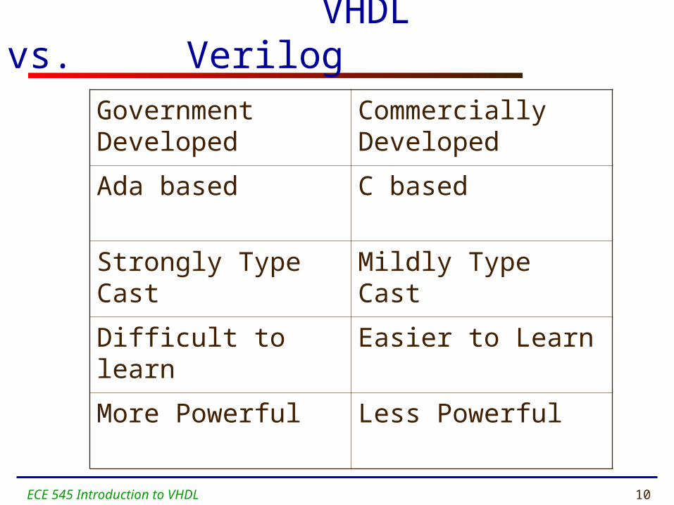
VHDL vs. Verilog
Government Developed
Commercially Developed
Ada based C based
Strongly Type Cast Mildly Type Cast
Difficult to learn Easier to Learn
More Powerful Less Powerful
ECE 545 Introduction to VHDL 11
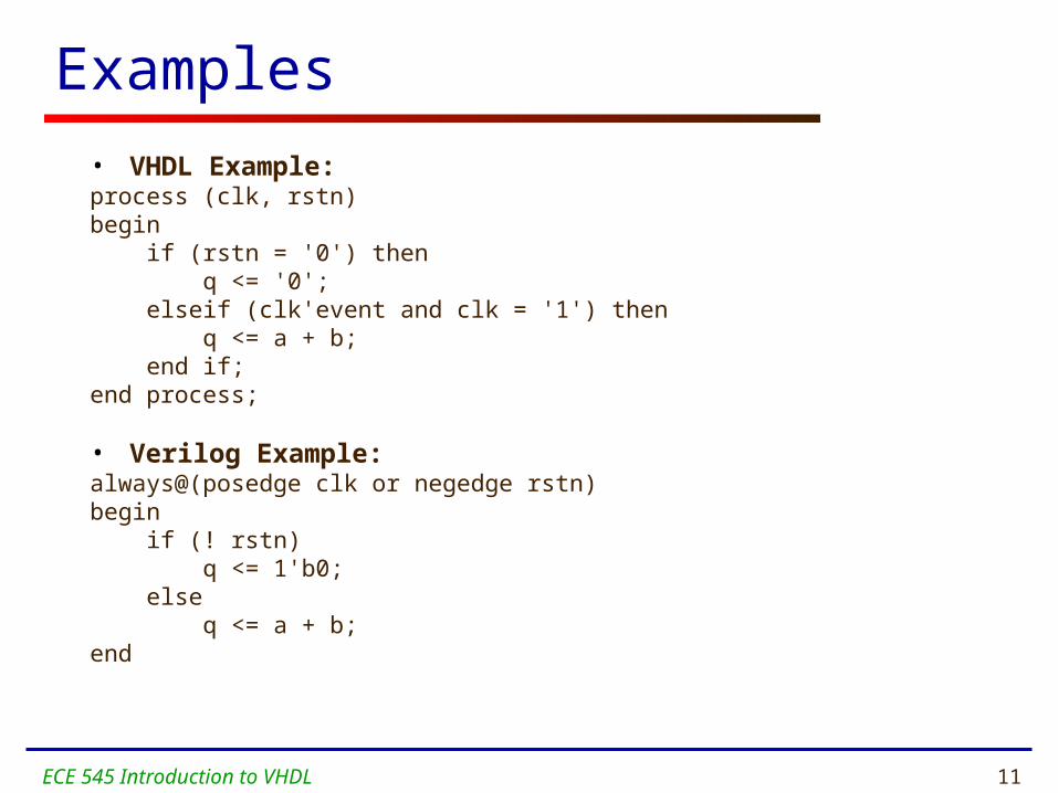
Examples
• VHDL Example:process (clk, rstn)begin if (rstn = '0') then q <= '0'; elseif (clk'event and clk = '1') then q <= a + b; end if;end process;
• Verilog Example:always@(posedge clk or negedge rstn)begin if (! rstn) q <= 1'b0; else q <= a + b;end

ECE 545 Introduction to VHDL 12
Features of VHDL and Verilog
• Technology/vendor independent
• Portable
• Reusable

ECE 545 Introduction to VHDL 13
Other
Hardware Description Languages
ECE 545 Introduction to VHDL 14
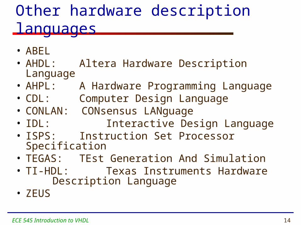
Other hardware description languages
• ABEL• AHDL: Altera Hardware Description
Language• AHPL: A Hardware Programming Language• CDL: Computer Design Language• CONLAN: CONsensus LANguage• IDL: Interactive Design Language• ISPS: Instruction Set Processor Specification• TEGAS: TEst Generation And Simulation• TI-HDL: Texas Instruments Hardware
Description Language• ZEUS
ECE 545 Introduction to VHDL 15
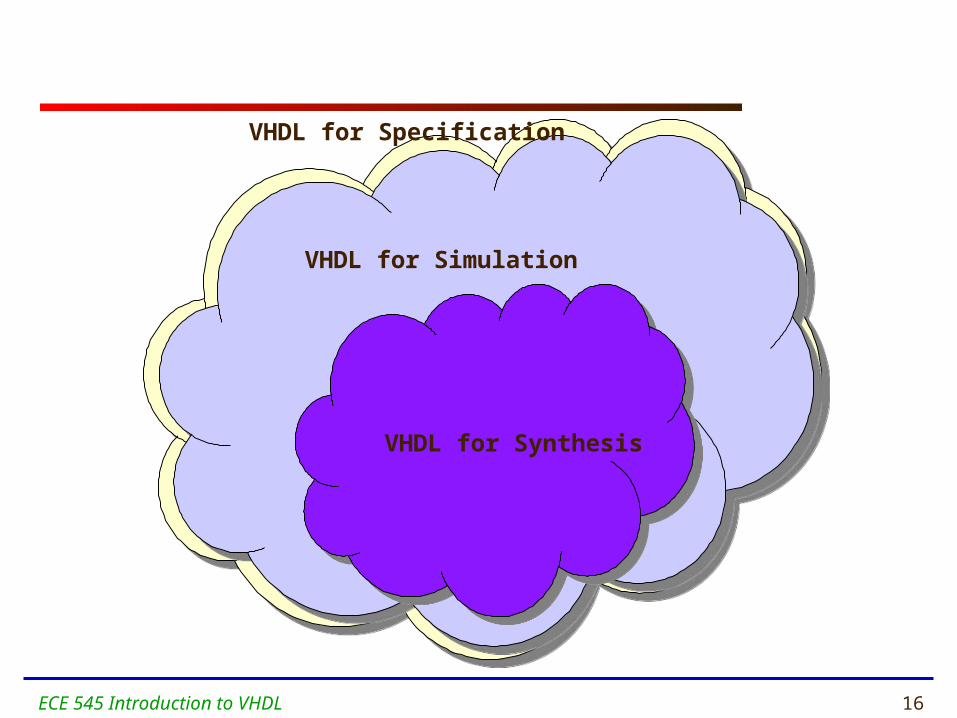
VHDL for Synthesis
ECE 545 Introduction to VHDL 16
VHDL for Specification
VHDL for Simulation
VHDL for Synthesis
ECE 545 Introduction to VHDL 17
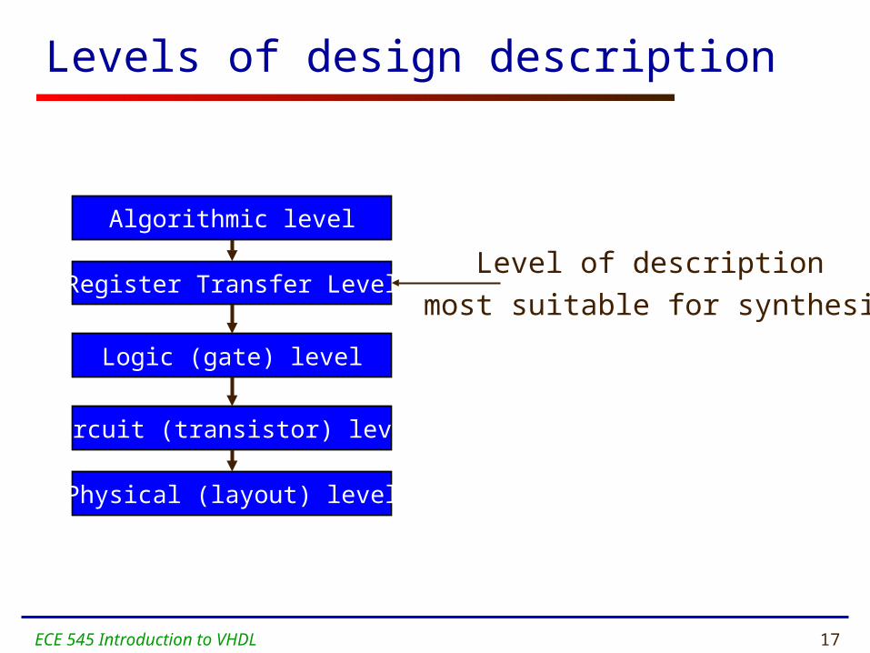
Levels of design description
Algorithmic level
Register Transfer Level
Logic (gate) level
Circuit (transistor) level
Physical (layout) level
Level of description
most suitable for synthesis
ECE 545 Introduction to VHDL 18
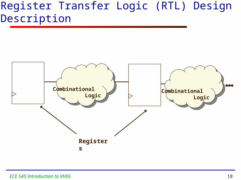
Register Transfer Logic (RTL) Design Description
Combinational Logic
Combinational Logic
Registers
…
ECE 545 Introduction to VHDL 19
VHDL Fundamentals

ECE 545 Introduction to VHDL 20
Naming and Labeling (1)
• VHDL is not case sensitiveExample:
Names or labels
databus
Databus
DataBus
DATABUS
are all equivalent
ECE 545 Introduction to VHDL 21
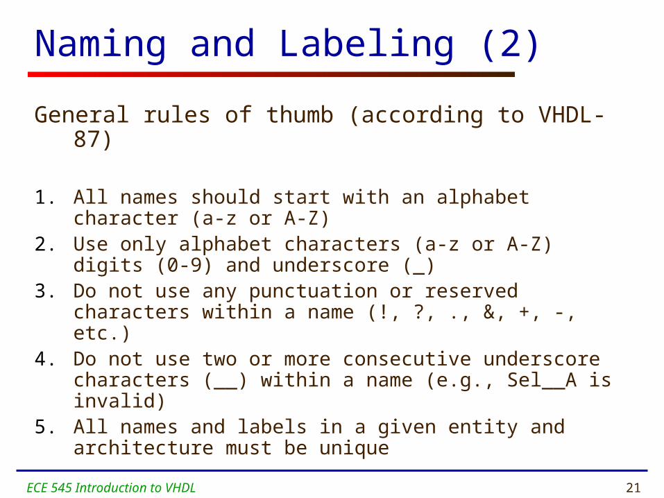
Naming and Labeling (2)
General rules of thumb (according to VHDL-87)
1. All names should start with an alphabet character (a-z or A-Z)
2. Use only alphabet characters (a-z or A-Z) digits (0-9) and underscore (_)
3. Do not use any punctuation or reserved characters within a name (!, ?, ., &, +, -, etc.)
4. Do not use two or more consecutive underscore characters (__) within a name (e.g., Sel__A is invalid)
5. All names and labels in a given entity and architecture must be unique
ECE 545 Introduction to VHDL 22
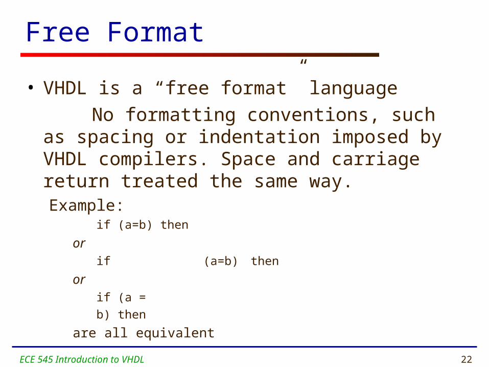
Free Format
• VHDL is a “free format” language
No formatting conventions, such as spacing or indentation imposed by VHDL compilers. Space and carriage return treated the same way.Example:
if (a=b) then
orif (a=b) then
orif (a =
b) then
are all equivalent
ECE 545 Introduction to VHDL 23
Readability standards
ESA VHDL Modelling Guidelines
published by
European Space Research and Technology Center
in September 1994
available at the course web page

ECE 545 Introduction to VHDL 24
Readability standards
Selected issues covered by ESA Guidelines:
• Consistent Writing Style• Consistent Naming Conventions• Consistent Indentation• Consistent Commenting Style• Recommended File Headers• File naming and contents• Number of statements/declarations per line• Ordering of port and signal declarations• Constructs to avoid

ECE 545 Introduction to VHDL 25
Comments
• Comments in VHDL are indicated with a “double dash”, i.e., “--”
Comment indicator can be placed anywhere in the line
Any text that follows in the same line is treated as a comment Carriage return terminates a comment No method for commenting a block extending over
a couple of linesExamples:-- main subcircuitData_in <= Data_bus; -- reading data from the input FIFO
ECE 545 Introduction to VHDL 26
Comments
• Explain Function of Module to Other Designers
• Explanatory, Not Just Restatement of Code
• Locate Close to Code Described• Put near executable code, not just in a header
ECE 545 Introduction to VHDL 27
Design Entity
ECE 545 Introduction to VHDL 28
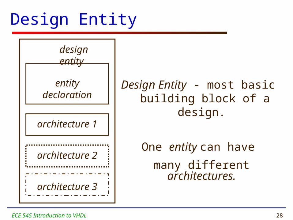
Design Entity
Design Entity - most basic building block of a design.
One entity can have
many different architectures.
entity declaration
architecture 1
architecture 2
architecture 3
design entity

ECE 545 Introduction to VHDL 29
Entity Declaration
• Entity Declaration describes the interface of the component, i.e. input and output ports.
ENTITY nand_gate ISPORT( a : IN STD_LOGIC;
b : IN STD_LOGIC; z : OUT STD_LOGIC
);END nand_gate;
Reserved words
Entity name Port names Port typeSemicolon
No Semicolon
Port modes (data flow directions)

ECE 545 Introduction to VHDL 30
Entity declaration – simplified syntax
ENTITY entity_name IS
PORT (
port_name : signal_mode signal_type;
port_name : signal_mode signal_type;
………….
port_name : signal_mode signal_type);
END entity_name;

ECE 545 Introduction to VHDL 31
Architecture
• Describes an implementation of a design entity.
• Architecture example:
ARCHITECTURE model OF nand_gate ISBEGIN
z <= a NAND b;END model;
ECE 545 Introduction to VHDL 32
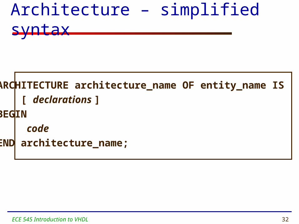
Architecture – simplified syntax
ARCHITECTURE architecture_name OF entity_name IS
[ declarations ]
BEGIN
code
END architecture_name;

ECE 545 Introduction to VHDL 33
Entity Declaration & Architecture
LIBRARY ieee;USE ieee.std_logic_1164.all;
ENTITY nand_gate ISPORT( a : IN STD_LOGIC;
b : IN STD_LOGIC; z : OUT STD_LOGIC);
END nand_gate;
ARCHITECTURE model OF nand_gate ISBEGIN
z <= a NAND b;END model;
nand_gate.vhd

ECE 545 Introduction to VHDL 34
Mode In
a
EntityPort signal
Driver resides
outside the entity
ECE 545 Introduction to VHDL 35
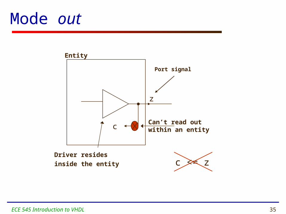
Mode out
Entity
Port signal
Driver resides
inside the entity
Can’t read out within an entity
z
c <= z
c
ECE 545 Introduction to VHDL 36
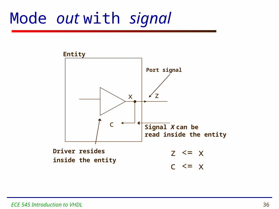
Mode out with signal
Port signal
Entity
Driver resides
inside the entity
Signal X can beread inside the entity
x
c
z
z <= x
c <= x
ECE 545 Introduction to VHDL 37
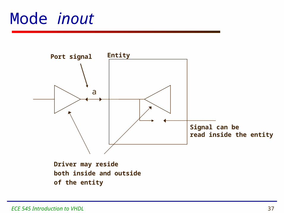
Mode inout
Signal can beread inside the entity
EntityPort signal
Driver may reside
both inside and outside
of the entity
a

ECE 545 Introduction to VHDL 38
Mode buffer
Entity
Port signal
Driver resides
inside the entity
Port signal Z can beread inside the entity
c
z
c <= z
ECE 545 Introduction to VHDL 39
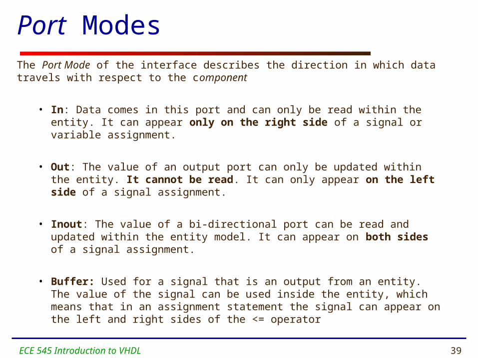
Port ModesThe Port Mode of the interface describes the direction in which data travels with respect to the component
• In: Data comes in this port and can only be read within the entity. It can appear only on the right side of a signal or variable assignment.
• Out: The value of an output port can only be updated within the entity. It cannot be read. It can only appear on the left side of a signal assignment.
• Inout: The value of a bi-directional port can be read and updated within the entity model. It can appear on both sides of a signal assignment.
• Buffer: Used for a signal that is an output from an entity. The value of the signal can be used inside the entity, which means that in an assignment statement the signal can appear on the left and right sides of the <= operator

ECE 545 Introduction to VHDL 40
Libraries
ECE 545 Introduction to VHDL 41
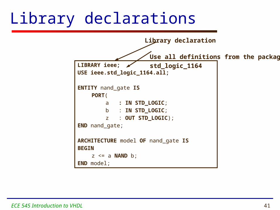
Library declarations
Use all definitions from the package
std_logic_1164LIBRARY ieee;USE ieee.std_logic_1164.all;
ENTITY nand_gate ISPORT( a : IN STD_LOGIC;
b : IN STD_LOGIC; z : OUT STD_LOGIC);
END nand_gate;
ARCHITECTURE model OF nand_gate ISBEGIN
z <= a NAND b;END model;
Library declaration

ECE 545 Introduction to VHDL 42
Library declarations - syntax
LIBRARY library_name;
USE library_name.package_name.package_parts;
ECE 545 Introduction to VHDL 43
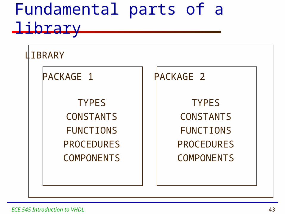
Fundamental parts of a library
LIBRARY
PACKAGE 1 PACKAGE 2
TYPES
CONSTANTS
FUNCTIONS
PROCEDURES
COMPONENTS
TYPES
CONSTANTS
FUNCTIONS
PROCEDURES
COMPONENTS
ECE 545 Introduction to VHDL 44
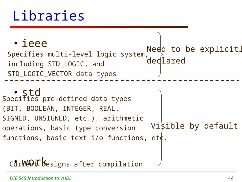
Libraries
• ieee
• std
• work
Need to be explicitly
declared
Visible by default
Specifies multi-level logic system,
including STD_LOGIC, and
STD_LOGIC_VECTOR data types
Specifies pre-defined data types
(BIT, BOOLEAN, INTEGER, REAL,
SIGNED, UNSIGNED, etc.), arithmetic
operations, basic type conversion
functions, basic text i/o functions, etc.
Current designs after compilation
ECE 545 Introduction to VHDL 45
STD_LOGIC Demystified

ECE 545 Introduction to VHDL 46
STD_LOGIC
What is STD_LOGIC you ask?
LIBRARY ieee;USE ieee.std_logic_1164.all;
ENTITY nand_gate ISPORT( a : IN STD_LOGIC;
b : IN STD_LOGIC; z : OUT STD_LOGIC);
END nand_gate;
ARCHITECTURE model OF nand_gate ISBEGIN
z <= a NAND b;END model;
ECE 545 Introduction to VHDL 47
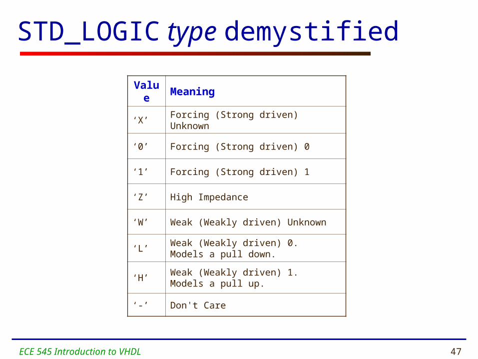
STD_LOGIC type demystified
Value Meaning
‘X’ Forcing (Strong driven) Unknown
‘0’ Forcing (Strong driven) 0
‘1’ Forcing (Strong driven) 1
‘Z’ High Impedance
‘W’ Weak (Weakly driven) Unknown
‘L’Weak (Weakly driven) 0.Models a pull down.
‘H’Weak (Weakly driven) 1. Models a pull up.
‘-’ Don't Care
ECE 545 Introduction to VHDL 48
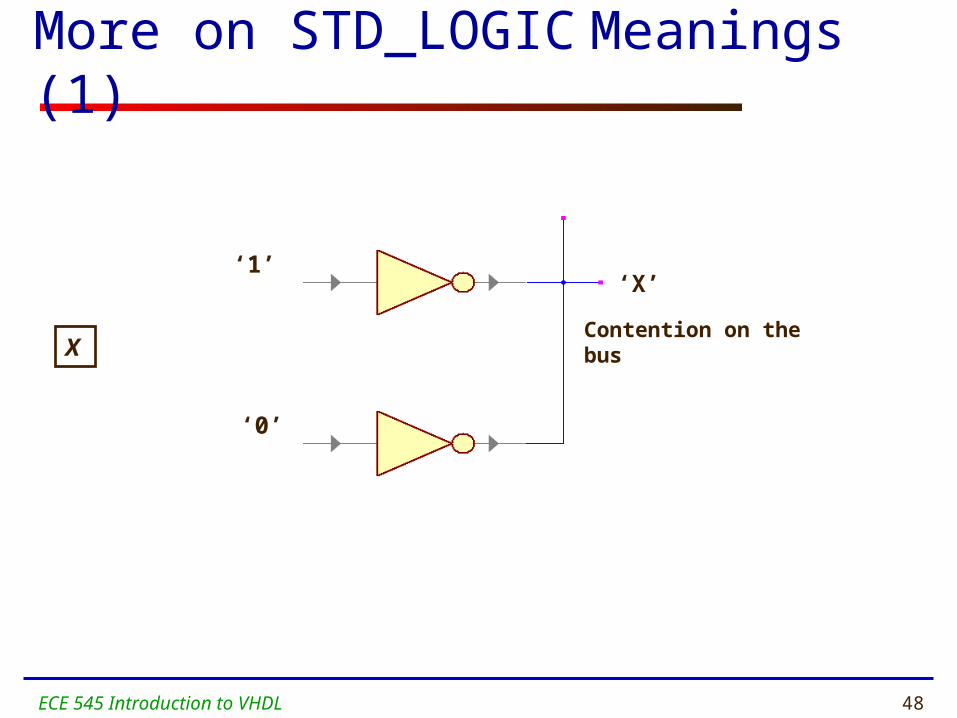
More on STD_LOGIC Meanings (1)
‘1’
‘0’
‘X’
Contention on the busX
ECE 545 Introduction to VHDL 49
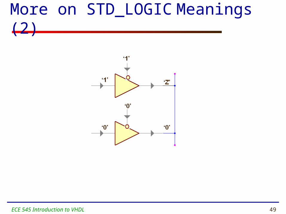
More on STD_LOGIC Meanings (2)

ECE 545 Introduction to VHDL 50
VDD
‘H’
‘0’
‘1’
‘L’
More on STD_LOGIC Meanings (3)
VDD

ECE 545 Introduction to VHDL 51
More on STD_LOGIC Meanings (4)
•Do not care.•Can be assigned to outputs for the case of invalid inputs(may produce significant improvement in resource utilization after synthesis).•Use with caution ‘1’ = ‘-’ give FALSE
‘-’

ECE 545 Introduction to VHDL 52
Resolving logic levels
X 0 1 Z W L H -
X X X X X X X X X
0 X 0 X 0 0 0 0 X
1 X X 1 1 1 1 1 X
Z X 0 1 Z W L H X
W X 0 1 W W W W X
L X 0 1 L W L W X
H X 0 1 H W W H X- X X X X X X X X

ECE 545 Introduction to VHDL 53
Modeling Wires and Buses
ECE 545 Introduction to VHDL 54
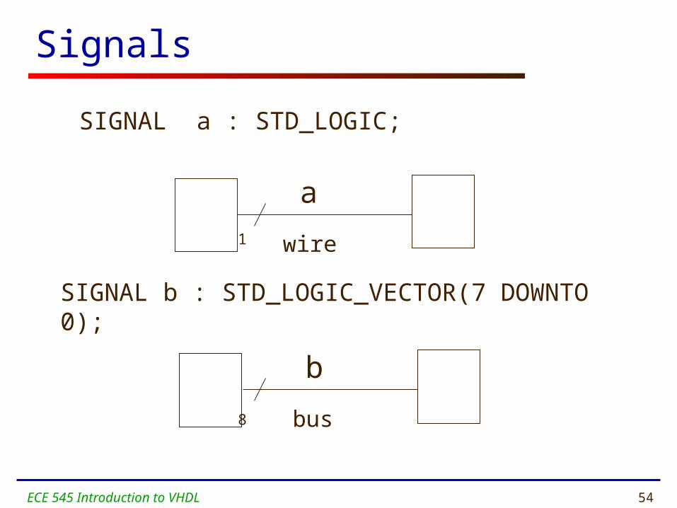
Signals
SIGNAL a : STD_LOGIC;
SIGNAL b : STD_LOGIC_VECTOR(7 DOWNTO 0);
wire
a
bus
b
1
8

ECE 545 Introduction to VHDL 55
Standard Logic VectorsSIGNAL a: STD_LOGIC;SIGNAL b: STD_LOGIC_VECTOR(3 DOWNTO 0);SIGNAL c: STD_LOGIC_VECTOR(3 DOWNTO 0);SIGNAL d: STD_LOGIC_VECTOR(7 DOWNTO 0);SIGNAL e: STD_LOGIC_VECTOR(15 DOWNTO 0);SIGNAL f: STD_LOGIC_VECTOR(8 DOWNTO 0); ……….a <= ‘1’;b <= ”0000”; -- Binary base assumed by defaultc <= B”0000”; -- Binary base explicitly specifiedd <= ”0110_0111”; -- You can use ‘_’ to increase readabilitye <= X”AF67”; -- Hexadecimal basef <= O”723”; -- Octal base
ECE 545 Introduction to VHDL 56
Vectors and Concatenation
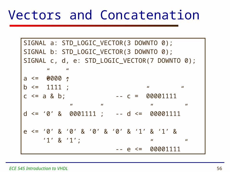
SIGNAL a: STD_LOGIC_VECTOR(3 DOWNTO 0);SIGNAL b: STD_LOGIC_VECTOR(3 DOWNTO 0);SIGNAL c, d, e: STD_LOGIC_VECTOR(7 DOWNTO 0);
a <= ”0000”; b <= ”1111”; c <= a & b; -- c = ”00001111”
d <= ‘0’ & ”0001111”; -- d <= ”00001111”
e <= ‘0’ & ‘0’ & ‘0’ & ‘0’ & ‘1’ & ‘1’ & ‘1’ & ‘1’; -- e <= ”00001111”

ECE 545 Introduction to VHDL 57
VHDL Design Styles
ECE 545 Introduction to VHDL 58
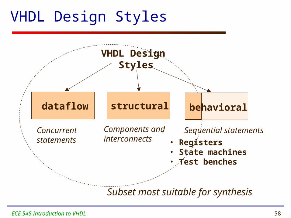
VHDL Design Styles
Components andinterconnects
structural
VHDL Design Styles
dataflow
Concurrent statements
behavioral
• Registers• State machines• Test benches
Sequential statements
Subset most suitable for synthesis
ECE 545 Introduction to VHDL 59
xor3 Example

ECE 545 Introduction to VHDL 60
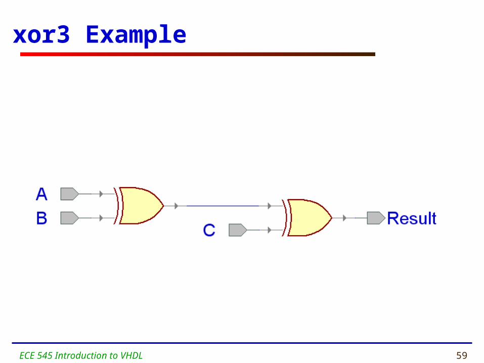
Entity xor3
ENTITY xor3 IS
PORT(
A : IN STD_LOGIC;
B : IN STD_LOGIC;
C : IN STD_LOGIC;
Result : OUT STD_LOGIC
);
end xor3;

ECE 545 Introduction to VHDL 61
Dataflow Architecture (xor3 gate)
ARCHITECTURE dataflow OF xor3 ISSIGNAL U1_out: STD_LOGIC;BEGIN
U1_out <=A XOR B;Result <=U1_out XOR C;
END dataflow;
U1_out
ECE 545 Introduction to VHDL 62
Dataflow Description
• Describes how data moves through the system and the various processing steps.
• Data Flow uses series of concurrent statements to realize logic. Concurrent statements are evaluated at the same time; thus, order of these statements doesn’t matter.
• Data Flow is most useful style when series of Boolean equations can represent a logic.

ECE 545 Introduction to VHDL 63
Structural Architecture (xor3 gate)
ARCHITECTURE structural OF xor3 ISSIGNAL U1_OUT: STD_LOGIC;
COMPONENT xor2 IS PORT(
I1 : IN STD_LOGIC; I2 : IN STD_LOGIC; Y : OUT STD_LOGIC
);END COMPONENT;
BEGINU1: xor2 PORT MAP (I1 => A,
I2 => B, Y =>
U1_OUT);
U2: xor2 PORT MAP (I1 => U1_OUT,
I2 => C, Y => Result);
END structural;
I1I2
Y
XOR2
AB
CRESULT
U1_OUT
XOR3
A
B
C
ResultXOR3
ECE 545 Introduction to VHDL 64
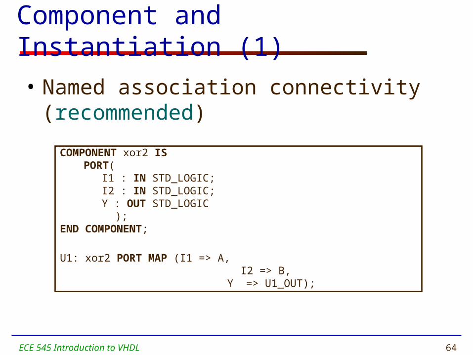
Component and Instantiation (1)
• Named association connectivity (recommended)
COMPONENT xor2 ISPORT(
I1 : IN STD_LOGIC; I2 : IN STD_LOGIC; Y : OUT STD_LOGIC
);END COMPONENT;
U1: xor2 PORT MAP (I1 => A, I2 => B,
Y => U1_OUT);
ECE 545 Introduction to VHDL 65
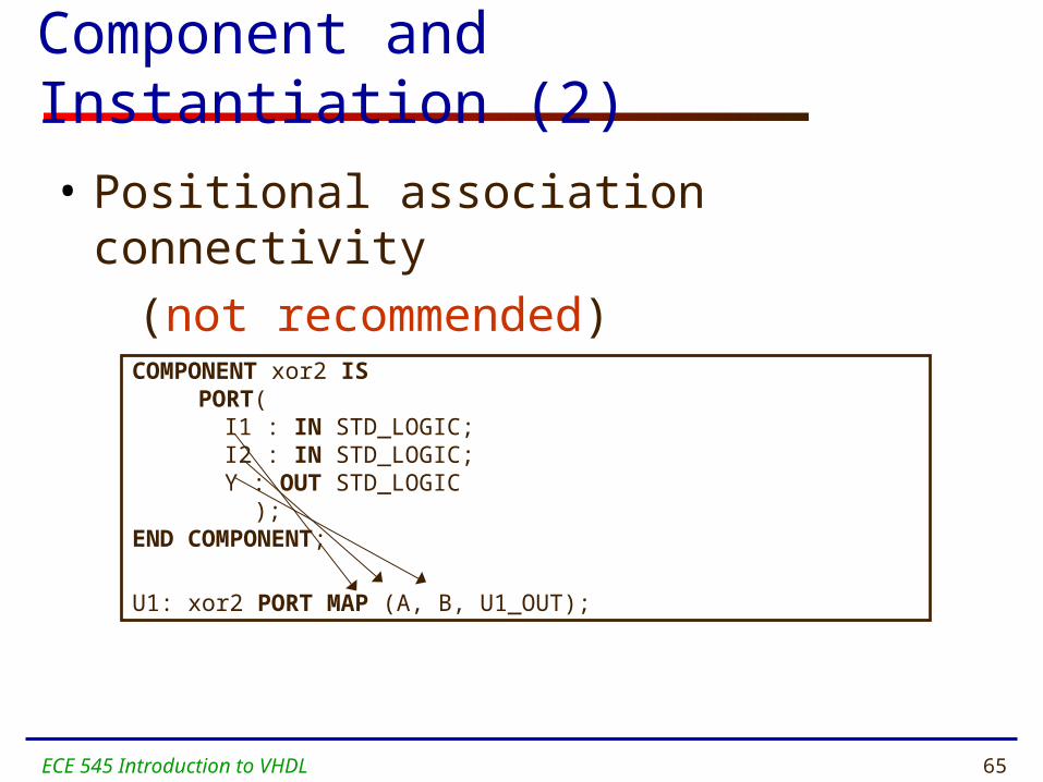
COMPONENT xor2 IS PORT(
I1 : IN STD_LOGIC; I2 : IN STD_LOGIC; Y : OUT STD_LOGIC
);END COMPONENT;
U1: xor2 PORT MAP (A, B, U1_OUT);
Component and Instantiation (2)
• Positional association connectivity
(not recommended)
ECE 545 Introduction to VHDL 66
Structural Description
• Structural design is the simplest to understand. This style is the closest to schematic capture and utilizes simple building blocks to compose logic functions.
• Components are interconnected in a hierarchical manner.
• Structural descriptions may connect simple gates or complex, abstract components.
• Structural style is useful when expressing a design that is naturally composed of sub-blocks.

ECE 545 Introduction to VHDL 67
Behavioral Architecture (xor3 gate)
ARCHITECTURE behavioral OF xor3 ISBEGINxor3_behave: PROCESS (A,B,C)BEGIN
IF ((A XOR B XOR C) = '1') THENResult <= '1';
ELSEResult <= '0';
END IF;END PROCESS xor3_behave;END behavioral;

ECE 545 Introduction to VHDL 68
Behavioral Description
• It accurately models what happens on the inputs and outputs of the black box (no matter what is inside and how it works).
• This style uses PROCESS statements in VHDL.

ECE 545 Introduction to VHDL 69
Testbenches
ECE 545 Introduction to VHDL 70
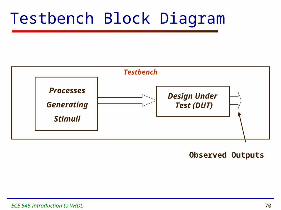
Testbench Block Diagram
Testbench
Processes
Generating
Stimuli
Design Under Test (DUT)
Observed Outputs
ECE 545 Introduction to VHDL 71
Testbench Defined
• Testbench applies stimuli (drives the inputs) to the Design Under Test (DUT) and (optionally) verifies expected outputs.
• The results can be viewed in a waveform window or written to a file.
• Since Testbench is written in VHDL, it is not restricted to a single simulation tool (portability).
• The same Testbench can be easily adapted to test different implementations (i.e. different architectures) of the same design.

ECE 545 Introduction to VHDL 72
Testbench AnatomyENTITY tb IS
--TB entity has no ports END tb;
ARCHITECTURE arch_tb OF tb IS
--Local signals and constants
COMPONENT TestComp --All Design Under Test component declarations PORT ( ); END COMPONENT;-----------------------------------------------------BEGIN testSequence: PROCESS -- Input stimuli END PROCESS;
DUT:TestComp PORT MAP( -- Instantiations of DUTs ); END arch_tb;
ECE 545 Introduction to VHDL 73
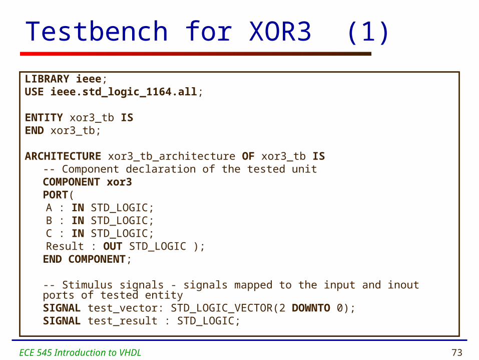
Testbench for XOR3 (1)
LIBRARY ieee;USE ieee.std_logic_1164.all;
ENTITY xor3_tb ISEND xor3_tb;
ARCHITECTURE xor3_tb_architecture OF xor3_tb IS-- Component declaration of the tested unitCOMPONENT xor3PORT(A : IN STD_LOGIC;B : IN STD_LOGIC;C : IN STD_LOGIC;Result : OUT STD_LOGIC );
END COMPONENT;
-- Stimulus signals - signals mapped to the input and inout ports of tested entitySIGNAL test_vector: STD_LOGIC_VECTOR(2 DOWNTO 0);SIGNAL test_result : STD_LOGIC;
ECE 545 Introduction to VHDL 74
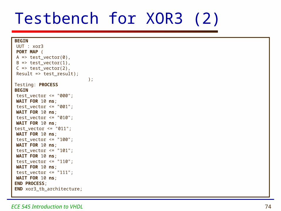
Testbench for XOR3 (2)BEGINUUT : xor3
PORT MAP (A => test_vector(0),B => test_vector(1),C => test_vector(2),Result => test_result);
);Testing: PROCESS BEGINtest_vector <= "000";WAIT FOR 10 ns;test_vector <= "001";WAIT FOR 10 ns;test_vector <= "010";WAIT FOR 10 ns;
test_vector <= "011";WAIT FOR 10 ns;test_vector <= "100";WAIT FOR 10 ns;test_vector <= "101";WAIT FOR 10 ns;test_vector <= "110";WAIT FOR 10 ns;test_vector <= "111";WAIT FOR 10 ns;
END PROCESS;END xor3_tb_architecture;
ECE 545 Introduction to VHDL 75
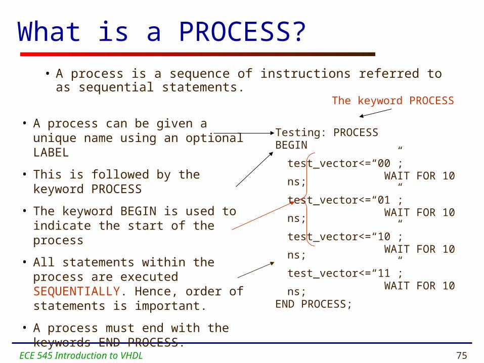
• A process can be given a unique name using an optional LABEL
• This is followed by the keyword PROCESS
• The keyword BEGIN is used to indicate the start of the process
• All statements within the process are executed SEQUENTIALLY. Hence, order of statements is important.
• A process must end with the keywords END PROCESS.
Testing: PROCESS BEGIN
test_vector<=“00”;WAIT FOR 10 ns;
test_vector<=“01”;WAIT FOR 10 ns;
test_vector<=“10”;WAIT FOR 10 ns;
test_vector<=“11”;WAIT FOR 10 ns;
END PROCESS;
• A process is a sequence of instructions referred to as sequential statements.
What is a PROCESS?
The keyword PROCESS

ECE 545 Introduction to VHDL 76
Execution of statements in a PROCESS
• The execution of statements continues sequentially till the last statement in the process.
• After execution of the last statement, the control is again passed to the beginning of the process.
Testing: PROCESS BEGIN
test_vector<=“00”;WAIT FOR 10 ns;test_vector<=“01”;WAIT FOR 10 ns;test_vector<=“10”;WAIT FOR 10 ns;test_vector<=“11”;WAIT FOR 10 ns;
END PROCESS;O
rde
r o
f exe
cutio
nProgram control is passed to the
first statement after BEGIN
ECE 545 Introduction to VHDL 77
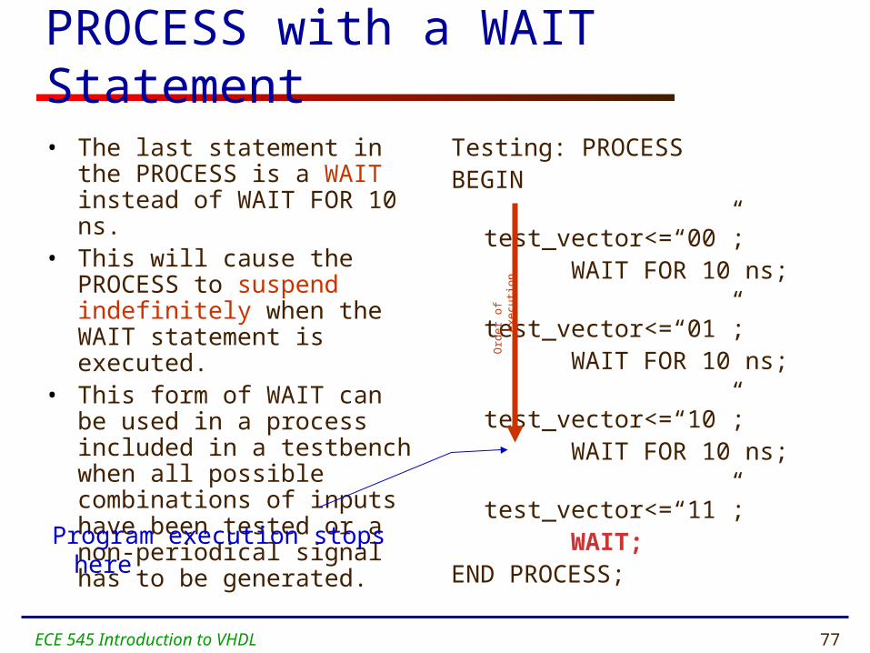
PROCESS with a WAIT Statement
• The last statement in the PROCESS is a WAIT instead of WAIT FOR 10 ns.
• This will cause the PROCESS to suspend indefinitely when the WAIT statement is executed.
• This form of WAIT can be used in a process included in a testbench when all possible combinations of inputs have been tested or a non-periodical signal has to be generated.
Testing: PROCESSBEGIN
test_vector<=“00”;WAIT FOR 10 ns;test_vector<=“01”;WAIT FOR 10 ns;test_vector<=“10”;WAIT FOR 10 ns;test_vector<=“11”;WAIT;
END PROCESS;
Program execution stops here
Ord
er
of e
xecu
tion

ECE 545 Introduction to VHDL 78
WAIT FOR vs. WAIT
WAIT FOR: waveform will keep repeating itself forever
WAIT : waveform will keep its state after the last wait instruction.
0 1 2 3
…
0 1 2 3 …
ECE 545 Introduction to VHDL 79
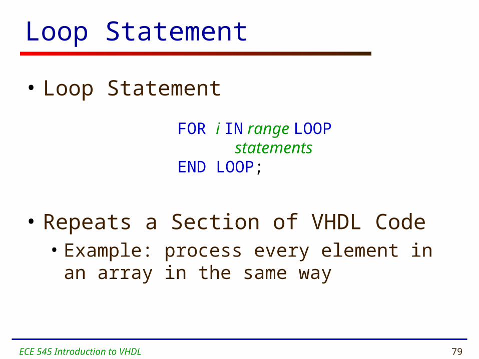
Loop Statement
• Loop Statement
• Repeats a Section of VHDL Code• Example: process every element in an array in
the same way
FOR i IN range LOOP statementsEND LOOP;

ECE 545 Introduction to VHDL 80
Testing: PROCESSBEGIN
test_vector<="000";FOR i IN 0 TO 7 LOOP WAIT FOR 10 ns; test_vector<=test_vector+”001";END LOOP;
END PROCESS;
Loop Statement – Example (1)

ECE 545 Introduction to VHDL 81
Testing: PROCESSBEGIN
test_ab<="00";test_sel<="00";FOR i IN 0 TO 3 LOOP
FOR j IN 0 TO 3 LOOPWAIT FOR 10 ns;test_ab<=test_ab+"01";
END LOOP;test_sel<=test_sel+"01";
END LOOP;END PROCESS;
Loop Statement – Example (2)

ECE 545 Introduction to VHDL 82
?