logic synthesis with vhdl combinational logicdropzone.tamu.edu/~wshi/468/vhdl_comb.pdflogic...
TRANSCRIPT

Logic Synthesis with VHDLCombinational Logic
Bob ReeseElectrical Engineering Department
Mississippi State University

Mississippi State UniversityElectrical & Computer Engineering
Combinational Synthesis with VHDLCombSyn–2 Bob Reese 5/95
Logic Synthesis
⇒ Use of Logic Synthesis has become common industrial practice.
The advantages are many:
→ Technology portability
→ Design Documentation
→ Constraint Driven Synthesis
⇒ Two major languages are Verilog and VHDL. This tutorial will con-
ver logic synthesis via VHDL.
⇒ We will split the tutorials into three parts:
→ Introduction to VHDL via combinational synthesis examples
→ Sequential synthesis examples (registers, finite state
machines)
→ System examples (combined datapath and control)

Mississippi State UniversityElectrical & Computer Engineering
Combinational Synthesis with VHDLCombSyn–3 Bob Reese 5/95
Tutorial Caveats
⇒ Tutorial examples have been made as simple and portable as pos-
sible.
→ Will stay away from topics such as parameterization which
may involve vendor–dependent features.
→ Will also stay away from coding styles which involve type
conversion as this tends to add extra complications.
⇒ Examples have been tested with the Synopsys and Viewlogic syn-
thesis tools; most of the synthesized schematics shown in the
slides are from the Viewlogic synthesis tool. Some of the more
complex examples are only compatible with the Synopsys envi-
ronment
⇒ In these tutorials, the suggested styles for writing synthesizable
VHDL models come from my own experience in teaching an
ASIC design course for Senior/Graduate EE students.
⇒ Coverage of VHDL packages will be light; the block structural
statements and VHDL configurations are skipped. Generics are
not mentioned until late in the tutorial since support from a synthe-
sis point of view is vendor dependent.
⇒ This tutorial is no substitute for a good, detailed VHDL textbook or
the language reference manual. Get one or both!!!
Mississippi State UniversityElectrical & Computer Engineering
Combinational Synthesis with VHDLCombSyn–4 Bob Reese 5/95
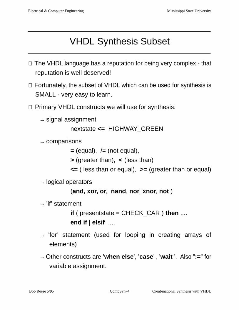
VHDL Synthesis Subset
⇒ The VHDL language has a reputation for being very complex - that
reputation is well deserved!
⇒ Fortunately, the subset of VHDL which can be used for synthesis is
SMALL - very easy to learn.
⇒ Primary VHDL constructs we will use for synthesis:
→ signal assignment
nextstate <= HIGHWAY_GREEN
→ comparisons
= (equal), /= (not equal),
> (greater than), < (less than)
<= ( less than or equal), >= (greater than or equal)
→ logical operators
(and, xor, or, nand, nor, xnor, not )
→ ’if’ statement
if ( presentstate = CHECK_CAR ) then ....
end if | elsif ....
→ ’for’ statement (used for looping in creating arrays of
elements)
→ Other constructs are ’when else’, ’case’ , ’wait ’. Also ”:=” for
variable assignment.

Mississippi State UniversityElectrical & Computer Engineering
Combinational Synthesis with VHDLCombSyn–5 Bob Reese 5/95
General Comments on VHDL Syntax
⇒ Most syntax details will be introduced on an ’as–needed’ basis.
→ The full syntax of a statement type including all of its various
options will often NOT be presented; instead, these will be
introduced via examples as the tutorial progresses.
→There are many language details which will be glossed over or
simply skipped for the sake of brevity.
⇒ Generalities:
→ VHDL is not case sensitive.
→ The semicolon is used to indicate termination of a statement.
→ Two dashes (’––’) are used to indicate the start of a comment.
→ Identifiers must begin with a letter, subsequent characters
must be alphanumeric or ’_’ (underscore).
→ VHDL is a strongly typed language. There is very little
automatic type conversion; most operations have to operate
on common types. Operator overloading is supported in
which a function or procedure can be defined differently for
different argument lists.

Mississippi State UniversityElectrical & Computer Engineering
Combinational Synthesis with VHDLCombSyn–6 Bob Reese 5/95
Combinational Logic Examples
⇒ We will go through some combinational examples to introduce you
to the synthesizable subset of VHDL. Usually, we will demon-
strate multiple methods of implementing the same design.
⇒ Examples are:
→ 2 to 1 Mux
→ 8-level priority circuit
→ 3 to 8 Decoder
→ Synthesis boundary conditions
→ Ripple–carry adder

Mississippi State UniversityElectrical & Computer Engineering
Combinational Synthesis with VHDLCombSyn–7 Bob Reese 5/95
Model Template
entity model_name is
port (
list of inputs and outputs);end model_name;
architecture architecture_name of model_name isbegin ... VHDL concurrent statements
....
end architecture_name ;

Mississippi State UniversityElectrical & Computer Engineering
Combinational Synthesis with VHDLCombSyn–8 Bob Reese 5/95
2–to–1 MUX –– Using when else
library IEEE;use IEEE.std_logic_1164.all;
–– vhdl model for 2 to 1 mux, 8–bits wideentity mux2to1 isport( signal s: in std_logic; signal zero,one: in std_logic_vector(7 downto 0); signal y: out std_logic_vector(7 downto 0) );end mux2to1;
architecture behavior of mux2to1 isbegin
y <= one when (s = ’1’) else zero;
end behavior; zero
y8
8
one
8
s
mux2to1

Mississippi State UniversityElectrical & Computer Engineering
Combinational Synthesis with VHDLCombSyn–9 Bob Reese 5/95
Standard Logic 1164
library IEEE;use IEEE.std_logic_1164.all;
⇒ The LIBRARY statement is used to reference a group of previous-
ly defined VHDL design units (other entities or groups proce-
dures/functions known as ’packages’.
⇒ The USE statement specifies what entities or packages to use out
of this library; in this case ’USE IEEE.std_logic_1164.all’ imports
all procedures/functions in the std_logic_1164 package.
⇒ The std_logic_1164 package defines a multi–valued logic system
which will be used as the data types for the signals defined in our
examples.
→ The VHDL language definition had a built–in bit type which
only supported two values, ’1’ and ’0’ which was insufficient
for modeling and synthesis applications.
→ The 1164 standard defines a 9–valued logic system; only 4 of
these have meaning for synthesis:
’1’, ’0’, ’Z’ ( high impedance), ’–’ (don’t care).
⇒ The 1164 single bit type std_logic and vector type std_logic_vec-
tor (for busses) will be used for all signal types in the tutorial exam-
ples.

Mississippi State UniversityElectrical & Computer Engineering
Combinational Synthesis with VHDLCombSyn–10 Bob Reese 5/95
2/1 MUX Entity Declaration
entity mux2to1 isport( signal s: in std_logic; signal zero,one: in std_logic_vector(7 downto 0); signal y: out std_logic_vector(7 downto 0) );end mux2to1;
⇒ The entity declaration defines the external interface for the model.
⇒ The port list defines the external signals. The signal definition con-
sists of the signal name, mode, and type.
→For synthesis purposes (and for this tutorial), the mode can be
either in, out or inout.
⇒ In this tutorial, the signal types will be either std_logic (single bit) or
std_logic_vector (busses).
⇒ The array specification on the std_logic_vector type defines the
width of signal:
std_logic_vector (7 downto 0) (descending range)
std_logic_vector (0 to 7) (ascending range)
Both of these are 8–bit wide signals. The descending/ascending
range declaration will affect assignment statements such as:
y <= ”11110000”;
For descending rage, y(7) is ’1’; for ascending range y(0) is ’1’.
Mississippi State UniversityElectrical & Computer Engineering
Combinational Synthesis with VHDLCombSyn–11 Bob Reese 5/95
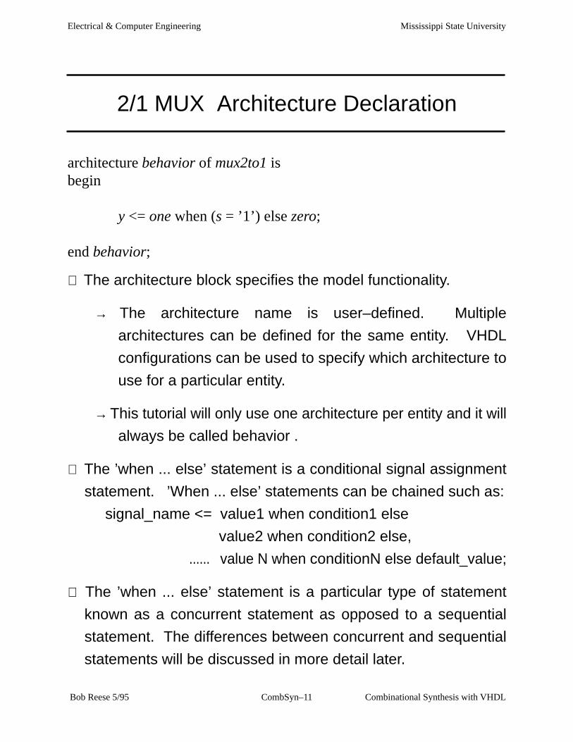
2/1 MUX Architecture Declaration
architecture behavior of mux2to1 isbegin
y <= one when (s = ’1’) else zero;
end behavior;
⇒ The architecture block specifies the model functionality.
→ The architecture name is user–defined. Multiple
architectures can be defined for the same entity. VHDL
configurations can be used to specify which architecture to
use for a particular entity.
→ This tutorial will only use one architecture per entity and it will
always be called behavior .
⇒ The ’when ... else’ statement is a conditional signal assignment
statement. ’When ... else’ statements can be chained such as:
signal_name <= value1 when condition1 else
value2 when condition2 else,
...... value N when conditionN else default_value;
⇒ The ’when ... else’ statement is a particular type of statement
known as a concurrent statement as opposed to a sequential
statement. The differences between concurrent and sequential
statements will be discussed in more detail later.

Mississippi State UniversityElectrical & Computer Engineering
Combinational Synthesis with VHDLCombSyn–12 Bob Reese 5/95
ZERO2
Y2
S
Y
BA
MX2
ONE2S
ZERO1
S
Y
BA
MX2
ONE1
Y1
ONE7
S
Y
BA
MX2
Y7
ZERO7
ONE0
S
Y
BA
MX2
ZERO0
Y0
ZERO5
S
Y
BA
MX2
Y5
ONE5
ONE6
S
Y
BA
MX2
Y6
ZERO6
Y4
S
Y
BA
MX2
ZERO4
ONE4
ONE3
S
Y
BA
MX2
ZERO3
Y3

Mississippi State UniversityElectrical & Computer Engineering
Combinational Synthesis with VHDLCombSyn–13 Bob Reese 5/95
2/1 MUX Architecture Using Booleans
architecture behavior of mux2to1 is signal temp: std_logic_vector(7 downto 0);
begin temp <= (s, s, s, s, others => s); y <= (temp and one) or (not temp and zero);
end behavior;
⇒ Boolean operators are used in an assignment statement to gener-
ate the mux operation.
⇒ The s signal cannot be used in a boolean operation with the one or
zero signals because of type mismatch (s is a std_logic type, one/
zero are std_logic_vector types)
→ An internal signal of type std_logic_vector called temp is
declared. Note that there is no mode declaration for internal
signals. The temp signal will be used in the boolean
operation against the zero/one signals.
⇒ Every bit of temp is to be set equal to the s signal value. An array
assignment will be used; this can take several forms:
temp <= (others => s); ’others’ keyword gives default value
temp <= (s, s, s, s, s, s, s, s) ; positional assignment, 7 downto 0
temp <= (4=>s, 7=>s, 2=>s, 5=>s, 3=>s, 1=>s, 6=>s, 0=>s) ;
named assignment
or combinations of the above.

Mississippi State UniversityElectrical & Computer Engineering
Combinational Synthesis with VHDLCombSyn–14 Bob Reese 5/95
2/1 MUX Architecture Using a Process
architecture behavior of mux2to1_8 isbegin comb: process (s, zero, one) begin y <= zero; if (s = ’1’) then y <= one; end if; end process comb;end behavior;
⇒ This architecture uses a process block to describe the mux opera-
tion.
→ The process block itself is considered a single concurrent
statement.
→ Only sequential VHDL statements are allowed within a
process block.
→Signal assignments are assumed to occur sequentially so that
an assignment can supercede a previous assignment to the
same signal.
→ ’if ... else’, ’case’, ’for ... loop’ are sequential statements.
⇒ The list of signals after the process block is called the sensitivity
list; an event on any of these signals will cause the process block
to be evaluated during model simulation.
Mississippi State UniversityElectrical & Computer Engineering
Combinational Synthesis with VHDLCombSyn–15 Bob Reese 5/95
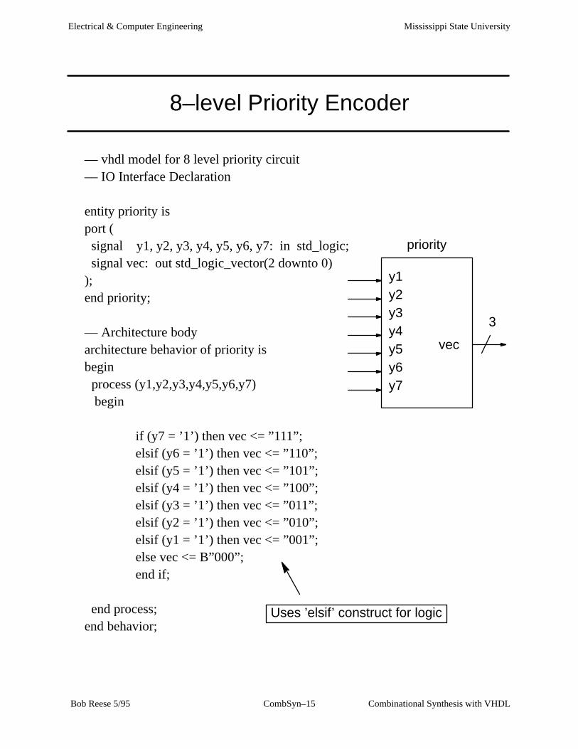
8–level Priority Encoder
–– vhdl model for 8 level priority circuit–– IO Interface Declaration
entity priority is port ( signal y1, y2, y3, y4, y5, y6, y7: in std_logic; signal vec: out std_logic_vector(2 downto 0) );end priority;
–– Architecture bodyarchitecture behavior of priority isbegin process (y1,y2,y3,y4,y5,y6,y7) begin
if (y7 = ’1’) then vec <= ”111”;elsif (y6 = ’1’) then vec <= ”110”;elsif (y5 = ’1’) then vec <= ”101”;elsif (y4 = ’1’) then vec <= ”100”;elsif (y3 = ’1’) then vec <= ”011”;elsif (y2 = ’1’) then vec <= ”010”;elsif (y1 = ’1’) then vec <= ”001”;else vec <= B”000”;end if;
end process;end behavior;
y1y2y3y4y5y6y7
vec
3
Uses ’elsif’ construct for logic
priority

Mississippi State U
niversityE
lectrical & C
omputer E
ngineering
Com
binational Synthesis with V
HD
LC
ombSyn–16
Bob R
eese 5/95
WIR:priority
SCH:priority
priority
SHEET 1 OF 16 Jan 94 13:36
1
2
3
4
1
2
3
4
FEDCBA
FEDCBA
Y7
Y3NAND2B
A
BY
Y2
YC
BAO1A
A
Y1
C
D
B
Y
A
AO2
YA
B NOR2
YC
BAO1A
A
YC
BAO1A
A
YOR4
B
C
D
A
Y4
Y5
Y6VEC2
VEC0
VEC1

Mississippi State UniversityElectrical & Computer Engineering
Combinational Synthesis with VHDLCombSyn–17 Bob Reese 5/95
Priority Encoder again.....
⇒ In a process, the ordering of sequential statements which affect a
common output define the priority of those assignments.
→ By using normal ’if’ statements and reversing the order of the
assignments we achieve the same results as with the
chained ’elsif’ statements.
–– Architecture bodyarchitecture behavior of priority isbegin process (y1,y2,y3,y4,y5,y6,y7) begin
vec <= ”000”;if (y1 = ’1’) then vec <= ”001”; end if;if (y2 = ’1’) then vec <= ”010”; end if;if (y3 = ’1’) then vec <= ”011”; end if;if (y4 = ’1’) then vec <= ”100”; end if;if (y5 = ’1’) then vec <= ”101”; end if;if (y6 = ’1’) then vec <= ”110”; end if;if (y7 = ’1’) then vec <= ”111”; end if;
end process;end behavior; Since ’y7’ is tested last it will have highest
priority.
Mississippi State UniversityElectrical & Computer Engineering
Combinational Synthesis with VHDLCombSyn–18 Bob Reese 5/95
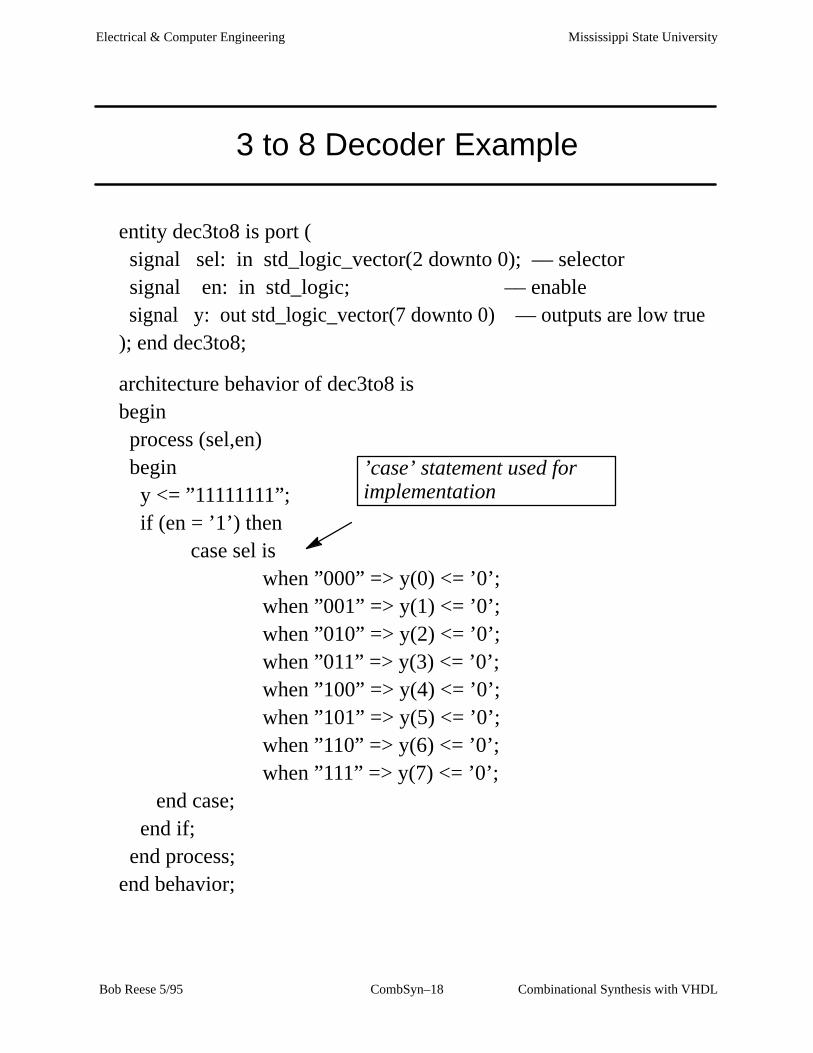
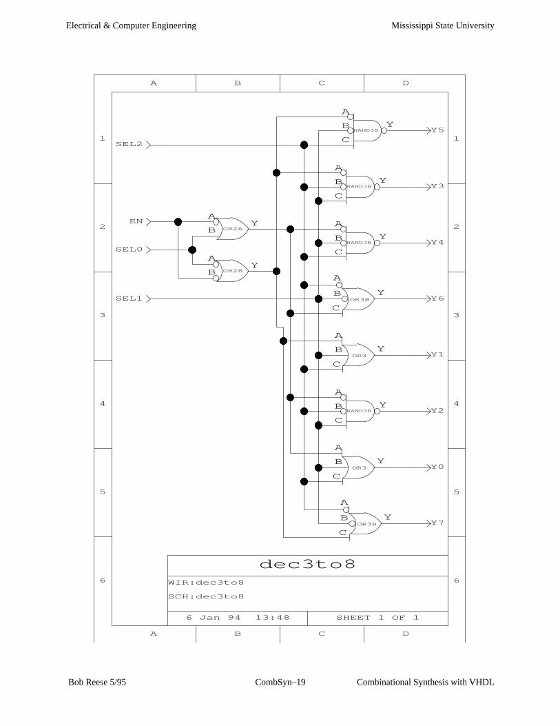
3 to 8 Decoder Example
entity dec3to8 is port ( signal sel: in std_logic_vector(2 downto 0); –– selector signal en: in std_logic; –– enable signal y: out std_logic_vector(7 downto 0) –– outputs are low true); end dec3to8;
architecture behavior of dec3to8 isbegin process (sel,en) begin y <= ”11111111”; if (en = ’1’) then
case sel iswhen ”000” => y(0) <= ’0’;
when ”001” => y(1) <= ’0’; when ”010” => y(2) <= ’0’; when ”011” => y(3) <= ’0’; when ”100” => y(4) <= ’0’; when ”101” => y(5) <= ’0’; when ”110” => y(6) <= ’0’; when ”111” => y(7) <= ’0’; end case; end if; end process;end behavior;
’case’ statement used forimplementation
Mississippi State UniversityElectrical & Computer Engineering
Combinational Synthesis with VHDLCombSyn–19 Bob Reese 5/95
WIR:dec3to8
SCH:dec3to8
dec3to8
SHEET 1 OF 16 Jan 94 13:48
1
2
3
4
5
6
1
2
3
4
5
6
DCBA
DCBA
Y7
SEL1
OR3B
C
Y
A
B
SEL0
AY
B OR2B
OR2A
AY
BEN
A
C
B YOR3 Y0
SEL2
Y
C
A
BNAND3B Y2
Y1
A
C
B YOR3
OR3B
C
Y
A
BY6
Y
C
A
BNAND3B Y4
Y
C
A
BNAND3B Y3
Y
C
A
BNAND3B Y5
Mississippi State UniversityElectrical & Computer Engineering
Combinational Synthesis with VHDLCombSyn–20 Bob Reese 5/95
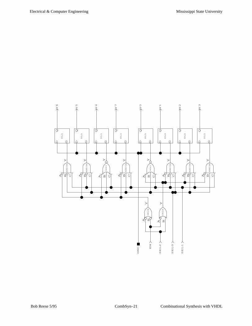
A Common Error
⇒ When using processes, a common error is to forget to assign an
output a default value. ALL outputs should have DEFAULT val-
ues!!!!
→ If there is a logical path in the model such that an output is not
assigned any value then the synthesizer will assume that the
output must retain its current value and a latch will be
generated.
⇒ Example: In dec3to8.vhd do not assign ’y’ the default value of
B”11111111”. If en is 0, then ’y’ will not be assigned a value!
process (sel,en)begin––––– y <= ”11111111”; if (en = ’1’) then ..........
Comment out the default assignment to ’y’.
⇒ In the new synthesized logic, all ’y’ outputs are latched!
Mississippi State UniversityElectrical & Computer Engineering
Combinational Synthesis with VHDLCombSyn–21 Bob Reese 5/95
SEL1
SEL0
Y3
Q
GD
DL1
Y
CBA
AND3A
Y2
Q
GD
DL1
Y
CBA
AND3B
Y1
Q
GD
DL1
Y
CBA
AND3B
SEL2
YBA
OR2A
EN
OR2B
A BY
Y
CBA
NOR3
Q
GD
DL1
Y0
Y7
Q
GD
DL1
Y
CBA
AND3A
Y4
Q
GD
DL1
Y
CBA
NOR3
Y
CBA
AND3B
Q
GD
DL1
Y5
Y
CBA
AND3B
Q
GD
DL1
Y6
GND

Mississippi State UniversityElectrical & Computer Engineering
Combinational Synthesis with VHDLCombSyn–22 Bob Reese 5/95
Alternative 3–to–8 Decoder
–– vhdl model for the 3 to 8 decoder–– uses conditional signal assignments–– which are concurrent statements
entity dec3to8_alt is port ( signal sel: in std_logic_vector(2 downto 0); –– selector signal en: in std_logic; –– enable
signal y: out std_logic_vector(7 downto 0) –– outputs are low true);end dec3to8_alt;
architecture behavior of dec3to8_alt isbegin
y(0) <= ’0’ when (en = ’1’ and sel = ”000”) else ’1’;
y(1) <= ’0’ when (en = ’1’ and sel = ”001”) else ’1’;
y(2) <= ’0’ when (en = ’1’ and sel = ”010”) else ’1’;
y(3) <= ’0’ when (en = ’1’ and sel = ”011”) else ’1’;
y(4) <= ’0’ when (en = ’1’ and sel = ”100”) else ’1’;
y(5) <= ’0’ when (en = ’1’ and sel = ”101”) else ’1’;
y(6) <= ’0’ when (en = ’1’ and sel = ”110”) else ’1’;
y(7) <= ’0’ when (en = ’1’ and sel = ”111”) else ’1’;
end behavior;
Conditional signalassignment usedfor each output bit.

Mississippi State UniversityElectrical & Computer Engineering
Combinational Synthesis with VHDLCombSyn–23 Bob Reese 5/95
Generic Decoder
⇒ Shown below is an architecture block for a generic decoder:
architecture behavior of generic_decoder isbegin process (sel, en) begin y <= (others => ’1’) ; for i in y’range loop if ( en = ’1’ and bvtoi(To_Bitvector(sel)) = i ) then y(i) <= ’0’ ; end if ; end loop; end process;end behavior;
⇒ This architecture block can be used for any binary decoder ( 2 to 4,
3 to 8, 4 to 16, etc).
⇒ The ’for ... loop’ construct is used to repeat a sequence of state-
ments.
→ The y’range is the range of values for loop variable ’i’. The
’range attribute of the signal ’y’ is defined as the array range
of the signal. In this case, ’i’ will vary from 7 to 0 if the array
range of ’y’ was defined as ”7 downto 0”.
→ Other attributes useful for synthesis are: ’LEFT, ’RIGHT (left,
right array indices); ’HIGH, ’LOW (max, min array indices);
’EVENT (boolean which is true if event occurred on signal).

Mississippi State UniversityElectrical & Computer Engineering
Combinational Synthesis with VHDLCombSyn–24 Bob Reese 5/95
Generic Decoder (cont.)
....
for i in y’range loop if ( en = ’1’ and bvtoi(To_Bitvector(sel)) = i ) then y(i) <= ’0’ ; end if ;
⇒ In order to compare loop variable i with the value of sel, a type con-
version must be done on sel to convert from std_logic_vector to
integer.
→ The Standard Logic 1164 package defines a conversion from
std_logic_vector to bit_vector (bit_vector is a primitive VHDL
type).
⇒ Unfortunately, the VHDL language standard does not define type
conversions between bit_vector and integer; these conversion
functions are vendor dependent.
→ ’bvtoi’ is the Synopsys bit_vector to integer conversion
function; ’vlb2int’ is the Viewlogic equivalent; the Cypress
WARP equivalent is ’bv2i’.

Mississippi State UniversityElectrical & Computer Engineering
Combinational Synthesis with VHDLCombSyn–25 Bob Reese 5/95
Synthesis Boundary Conditions
–– synthesis ’boundary’ conditions..entity boundtest is port ( signal a,b,c: in std_logic; signal w, x, y, z_low, z_high: out std_logic); end boundtest;
architecture behavior of boundtest isbegin
–– x and y reduce to the same logic equation–– the w output should be just a wire from c...–– the z_low output will be ’0’, the z_high will be ’1’ x <= a or b; y <= a or ( (b and not c) or (b and c)); w <= (c and b) or (c and not b); z_low <= b and not b; z_high <= b or not b;
end behavior;
What happens when:
Two outputs are reduced to the same logic equation?
An output is is reduced to ’0’, ’1’ or to a primary input?

Mississippi State U
niversityE
lectrical & C
omputer E
ngineering
Com
binational Synthesis with V
HD
LC
ombSyn–26
Bob R
eese 5/95
WIR:boundtest
SCH:boundtest
boundtest
SHEET 1 OF 16 Jan 94 13:55
1
2
3
4
1
2
3
4
FEDCBA
FEDCBA
WINVAA Y
INVAA Y
C
INVAA Y
INVAA Y
Z_HIGH
B
A
YNAND2B
A
BY
NAND2B
A
BY
X
INVAA Y
INVAA Y
Z_LOW
VDD
GND

Mississippi State UniversityElectrical & Computer Engineering
Combinational Synthesis with VHDLCombSyn–27 Bob Reese 5/95
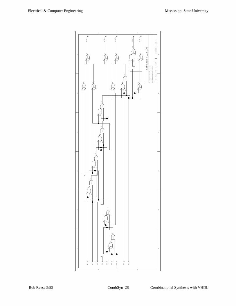
Ripple Carry Adder
Library IEEE;use IEEE.std_logic_1164.all;
entity adder4 is port ( signal a,b: in std_logic_vector (3 downto 0); signal cin: in std_logic; signal sum: out std_logic_vector(3 downto 0); signal cout: out std_logic); end adder4;
architecture behavior of adder4 is signal c: std_logic_vector(4 downto 0); begin process (a,b,cin,c) begin c(0) <= cin; for i in 0 to 3 loop sum(i) <= a(i) xor b(i) xor c(i); c(i+1) <= (a(i) and b(i)) or
(c(i) and (a(i) or b(i))); end loop; cout <= c(4); end process; end behavior;
Explicit CarryInand CarryOut
Temporary signalto hold internalcarries.
Use Looping construct tocreate logic for ripple carryadder.
Mississippi State UniversityElectrical & Computer Engineering
Combinational Synthesis with VHDLCombSyn–28 Bob Reese 5/95
WIR:adder4_alt
SCH:adder4_alt
adder4_alt
SHEET 1 OF 1
6 Jan 94 14:07
1 2
1 2
FE
DC
BA
FE
DC
BA
B3
A3
A BY
XOR
A BY
XOR
YCBA
AO1
CY
OA1
A B
CIN
A BY
XOR
A BY
XOR
B0
CY
OA1
A BA0
YCBA
AO1
A2
A BY
XOR
YCBA
AO1
CY
OA1
A BB2
A BY
XOR
YCBA
AO1
CY
OA1
A BA1
A BY
XOR
A BY
XOR
B1
SUM1
SUM2
SUM0
COUT
SUM3

Mississippi State UniversityElectrical & Computer Engineering
Combinational Synthesis with VHDLCombSyn–29 Bob Reese 5/95
Ripple Carry Adder Comments
⇒ The Standard Logic 1164 package does not define arithmetic op-
erators for the std_logic type.
⇒ Most vendors supply some sort of arithmetic package for 1164
data types.
→ Some vendors also support synthesis using the ’+’ operation
between two std_logic signal types (Synopsis). Others
provide an explicit function call (Viewlogic).
→ For code portability, it is best to avoid use of vendor–specific
arithmetic functions.

Mississippi State UniversityElectrical & Computer Engineering
Combinational Synthesis with VHDLCombSyn–30 Bob Reese 5/95
Summary
⇒ Logic synthesis offers the following advantages:
→ Faster design time, easier to modify
→ The synthesis code documents the design in a more readable
manner than schematics.
→ Different optimization choices (area or speed)
⇒ Several combinational VHDL examples were examined.
→ Both concurrent and sequential statements can be used to
specify combination logic – which you use is up to individual
preference.