laird automotive emi shielding white paper
TRANSCRIPT
8/10/2019 Laird Automotive EMI Shielding White Paper
http://slidepdf.com/reader/full/laird-automotive-emi-shielding-white-paper 1/14
Automotive EMI Shielding –Controlling Automotive ElectronicEmissions and Susceptibility withProper EMI Suppression Methods
By: John Noto, Gary Fenical, and Colin Tong
Date: Apri l 1, 2010
White Paper As technology advances, the need to place largernumbers of electrical and electronic systems intoautomobiles has dramatically increased. To name a few,these systems include Control Area Networks (CAN),safety systems, communications, mobile media,infotainment systems including wireless headsets, DC
motors and controllers. The physical size of these systemsis greatly reduced because of the size and weightconstraints involved with automotive design. Thesesystems may be small, but it does not necessarily meantheir electromagnetic emissions are too.
As the electronics systems become more complex,the wiring systems turn out to be a major cost in themanufacturing process. They turn out to be a major failurepoint also. The current trend is to make as many systemsas possible wireless, lowering the manufacturing cost andimproving the reliability of the systems by eliminating the
wiring.Placing a large amount of electrical and electronic
systems into a very confined space poses the problem ofkeeping the Electromagnetic Interference (EMI) of thesesystems from interfering with each other through radiatedand conducted emissions, sometimes referred to ascrosstalk. If not properly controlled, the interference cancause each system to malfunction, and even fail. Withmost systems now fully electronic, the need to contain EMIis more vital than ever.
This White Paper discusses the various electronicsystems found on automobiles, and addresses the need ofcontaining and suppressing their EMI potential with eachother through EMI shielding and ferrite solutions.
8/10/2019 Laird Automotive EMI Shielding White Paper
http://slidepdf.com/reader/full/laird-automotive-emi-shielding-white-paper 2/14
What is EMI?
EMI is a process by which disruptive electromagnetic energy is transmitted from oneelectronic device to another via radiated or conducted paths, or both. In an automotiveelectronic system, EMI can adversely affect the performance of an integrated circuitinternally, as well as that of other electronic components in close proximity.
There is a root cause to most EMI noise. In a digital system, clock pulses aregenerated to operate the logic. As these clock pulses are developed (typically a squarewaveform), they have a given rise time. The rise time, as it gets shorter, has a tendency tocreate a broadband energy pulse on the leading edge. This is commonly known asovershoot and ringing.
The energy present in the overshoot and ringing is the basis for generating otherhigher frequencies called harmonics. These higher frequencies are multiples of the clockfrequency. Both odd and even multiples (harmonics) exist. In most cases, the oddharmonics (observed at 3, 5, 7, and 9 etc. times the desired or fundamental clock frequency)create most of the EMI noise problems. However, even harmonics do exist and must not beignored.
Another EMI issue involves intentional transmitters such as mobile phones,Bluetooth® devices, and even commercial broadcast signals. The EMI of these externalsources will interfere with the vehicle’s electronic system when the vehicle is in closeproximity to the transmitting antenna. In short, the new automotive electromagneticenvironment is a very complex one involving many internal and external factors.
EMI Sources and Potential Receptors Internal to the Vehicle
EMI problems can manifest themselves as simple nuisances such as static on theradio. Or they can create a dangerous problem such as loss of control of the vehicle.Special care must be given to “mission critical” systems; especially those that deal with thecontrol and safety of the vehicle (see Appendix). Some of these internal systems include:
•
Collision avoidance radar• Console applications
• Navigation-radio combination
• Power steering module
• Infotainment head unit
• Airbag inflator
• ECU and other module connector
• Tire pressure monitoring
• CAN Bus
• DC motors
• Ignition system
• Engine control module
• Electronic Braking Systems
• Fuel Control Systems
• Adaptive cruise control
Page 2© Copyright 2010 Laird Technologies. All Rights Reserved.
8/10/2019 Laird Automotive EMI Shielding White Paper
http://slidepdf.com/reader/full/laird-automotive-emi-shielding-white-paper 3/14
EMI Sources External to the Vehicle
Automotive and other transportation electronics can be affected by harsh externalEMI environments. Of course it is impossible to control the emissions from the externalsources since EMI can be generated from power transients, radio frequency interference,electrostatic discharge, and power line electric and magnetic fields. So, the designer mustprovide for immunity to these threats. Proper EMI design including filtering, grounding andshielding is essential (see Appendix). If EMI is not considered at the beginning stages of the
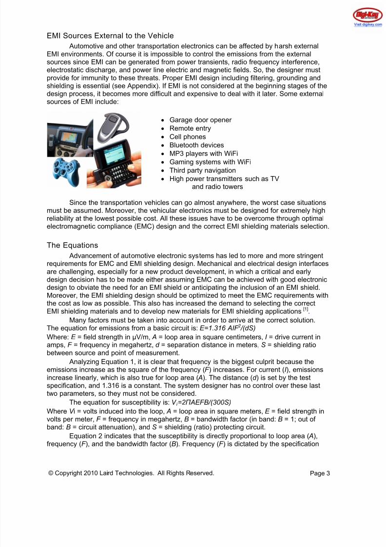
design process, it becomes more difficult and expensive to deal with it later. Some externalsources of EMI include:
• Garage door opener
• Remote entry
• Cell phones
• Bluetooth devices
• MP3 players with WiFi
• Gaming systems with WiFi
• Third party navigation
• High power transmitters such as TVand radio towers
Since the transportation vehicles can go almost anywhere, the worst case situationsmust be assumed. Moreover, the vehicular electronics must be designed for extremely highreliability at the lowest possible cost. All these issues have to be overcome through optimalelectromagnetic compliance (EMC) design and the correct EMI shielding materials selection.
The Equations
Advancement of automotive electronic systems has led to more and more stringentrequirements for EMC and EMI shielding design. Mechanical and electrical design interfacesare challenging, especially for a new product development, in which a critical and earlydesign decision has to be made either assuming EMC can be achieved with good electronic
design to obviate the need for an EMI shield or anticipating the inclusion of an EMI shield.Moreover, the EMI shielding design should be optimized to meet the EMC requirements withthe cost as low as possible. This also has increased the demand to selecting the correctEMI shielding materials and to develop new materials for EMI shielding applications [1].
Many factors must be taken into account in order to arrive at the correct solution.The equation for emissions from a basic circuit is: E=1.316 AIF 2 /(dS)
Where: E = field strength in µV/m, A = loop area in square centimeters, I = drive current inamps, F = frequency in megahertz, d = separation distance in meters, S = shielding ratiobetween source and point of measurement.
Analyzing Equation 1, it is clear that frequency is the biggest culprit because theemissions increase as the square of the frequency (F ) increases. For current (I ), emissionsincrease linearly, which is also true for loop area ( A). The distance (d ) is set by the test
specification, and 1.316 is a constant. The system designer has no control over these lasttwo parameters, so they must not be considered.
The equation for susceptibility is: V i =2 Π AEFB/(300S)
Where V i = volts induced into the loop, A = loop area in square meters, E = field strength involts per meter, F = frequency in megahertz, B = bandwidth factor (in band: B = 1; out ofband: B = circuit attenuation), and S = shielding (ratio) protecting circuit.
Equation 2 indicates that the susceptibility is directly proportional to loop area ( A),frequency (F ), and the bandwidth factor (B). Frequency (F ) is dictated by the specification
Page 3© Copyright 2010 Laird Technologies. All Rights Reserved.
8/10/2019 Laird Automotive EMI Shielding White Paper
http://slidepdf.com/reader/full/laird-automotive-emi-shielding-white-paper 4/14
and the operating environment, as is the field strength (E ). Of course, the engineer has nocontrol over 2π, or 300, which is the speed of light divided by 1,000,000 for this equation.
From the equations, it is possible to determine some key information. Emissionlevels are:
• Directly related to loop area.
• Directly related to signal current.
• A function of frequency squared.
• Inversely related to shielding effectiveness.Susceptibility levels are:
• Directly related to loop area.
• Directly related to bandwidth.
• Directly related to the transmitted frequency and field strength.
• Inversely related to shielding effectiveness.EMI can be reduced by a number of ways:
• Move components on the PCB.
• Add/change ground planes.
• Reduce the length of noisy PCB traces and wires.
• Match driver and return circuit traces or cable lines to cancel magnetic signalsand reduce loop area.
• Add special components, i.e., inductors, capacitors, resistors, or combinations ofthese parts.
• Change circuit components - less noisy components.
• Add ferrite products. Ferrites will absorb the EMI energy, dissipating it as smallamounts of heat, typically in microwatts.
• Use special shielding techniques.
For radiated EMI, once proper circuit layout is developed (minimize frequency,current and loop area), if the circuit still does not meet its EMI requirements, the only thingleft to do is provide some sort of shielding. It is always more efficient and less expensive todeal with EMI suppression at the source. Therefore, board-level shields (BLS) are the mostcost-effective and generally the most efficient type of shielding. However, it is essential that
BLS be designed in at the beginning of the design process because one needs to providefor proper attachment to the printed circuit board (PCB). As good as BLS may be, it is notalways the entire solution.
The enclosure of the device may have to be made of electrically conductive materialsto block electromagnetic fields, e.g., foil, metal, metalized plastic, conductive fabric, etc. Oneapproach may be to build a conductive box around the device or affected components. Thisinvolves placing the system or device that is producing the EMI into a conductive box andsealing the box. This employs EMI gaskets such as Fabric-over-Foam (FoF), CF, wire mesh,fingerstock, BLS, etc.
Used more at system level, EMI radio frequency (RF) absorbers and ferrites absorband dissipate electromagnetic fields. The absorber sheet can be applied to the housing ofthe system or device creating the EMI. Ferrite chips and RF absorbers can be placed
directly onto the system or device.
Shielding does little to nothing for Conducted EMI. The noise (EMI) needs to beeliminated while not eliminating the desired signals. This is generally solved by using a filterto select out the offending noise and allow through the good signals. Most filters arefrequency specific. Ferrites can act as filters and absorbers.
Page 4© Copyright 2010 Laird Technologies. All Rights Reserved.
8/10/2019 Laird Automotive EMI Shielding White Paper
http://slidepdf.com/reader/full/laird-automotive-emi-shielding-white-paper 5/14
When determining the correct ferrite solution to an EMI problem, many issues mustbe taken into account: frequency, signal current (intended), noise current, and if the signaland noise currents are the same frequency. Many ferrite properties are frequencydependent. Other considerations are:
• Current
• Amp - Turns of Signal Current
• Amp - Turns of Bias Current
•
Core Saturation• Part Size
• Common Mode or Differential Mode Solution
• Temperature
• Permeability vs. Temperature
• Impedance vs. Temperature
• Curie Temperature
• Single or Multi-Line
• Isolation Resistivity
EMC Design
EMC can be achieved from different design levels, such as from chip level integrateddesign, PCB, module or enclosure, and interconnect to software control. Different designtechniques have been developed for various EMI problems, depending on the particularsystem, its electronic design, and the type of interference source.
For instance, EMC design techniques for power transients need to provide primarytransient protection on all module input power lines, plus secondary protection such asfiltering at the circuit level. The load dump transient is usually the biggest concern.
Designing noise tolerant software is also very effective in controlling susceptibility topower line transients. The design techniques for radio frequency immunity are to keep theunwanted energy from reaching vulnerable circuits. This requires high frequency filtering onboth power and I/O cables which act as antennas, plus careful circuit layout and circuitdecoupling. Cable and module shielding are also effective, but are not popular in vehicular
designs due to the costs.The design techniques for electrostatic discharge (ESD) are to limit damage by
transient suppression or high frequency filtering on I/O and power lines, and to limit upsetsby local filtering and decoupling, careful circuit layouts, and perhaps even shielding. Many ofthe design techniques for EMI emissions and immunity work equally well for the indirectESD effects due to the transient electromagnetic fields.
The design techniques for power line fields are usually instrumentation oriented, andinclude local shielding and filtering of the most critical circuits. The design techniquesnecessary for EMI emissions and immunity also minimize this threat. This is normally not aserious threat.
The design techniques for radiated emissions are to suppress the emissions at thesource by careful circuit layout, filtering, and grounding, or to confine the emissions by
shielding. For automotive designs, the emphasis has usually been on suppression andcareful circuit layout, since shielding is costly and difficult for most high volume automotiveproducts. Nevertheless, shielding use is increasing in vehicular applications.
Page 5© Copyright 2010 Laird Technologies. All Rights Reserved.
8/10/2019 Laird Automotive EMI Shielding White Paper
http://slidepdf.com/reader/full/laird-automotive-emi-shielding-white-paper 6/14
Selecting Proper Materials
Many factors affect the proper selection of RF gasket materials. The following listidentifies some of the key issues that must be considered. The list has been developed overmany years and includes essential considerations for choosing RF gasket materials toensure that the materials achieve their advertised specifications. The list includes:
• Operating frequency
• Materials compatibility
• Corrosive considerations
• EMC compliance specification (SAE, FMC, GM, etc.)
• Operating environment
• Load and forces
• Cost
• Attenuation performance
• Storage environment
• Oil and fuel resistance
• Cycle life
• Shielding, grounding, etc.
• Electrical requirements• Materials thickness / alloy
• Space and weight considerations
• Product safety
• Recyclability
Shielding
Shielding, which is noninvasive and does not affect high-speed operation, works forboth emissions and susceptibility. It can be a stand-alone solution, but is more cost-effectivewhen combined with other suppression techniques such as filtering, grounding, and properdesign to minimize the loop area. It is also important to note that shielding usually can beinstalled after the design is complete. However, it is much more cost-effective and generallymore efficient to design shielding into the device from the beginning as part of the designprocess. It is important to keep in mind that the other suppression techniques generallycannot be added easily once the device has gone beyond the prototype stage.
The use of shielding can take many forms, from RF gaskets to BLS. An RF gasketprovides a good EMI / EMP seal across the gasket-flange interface. The ideal gaskettingsurface is conductive, rigid, galvanic-compatible and recessed to completely house thegasket.
A device housed in a metal case is generally a good candidate for RF gasketingmaterials. When electrical and electronic circuits are in nonconductive enclosures, or when itis difficult or impossible to use RF gasketing, BLS provides the best option for EMI
suppression. A properly designed and installed BLS can actually eliminate the entire looparea because the offending or affected circuit will be contained within the shield.
Page 6© Copyright 2010 Laird Technologies. All Rights Reserved.
8/10/2019 Laird Automotive EMI Shielding White Paper
http://slidepdf.com/reader/full/laird-automotive-emi-shielding-white-paper 7/14
Page 7© Copyright 2010 Laird Technologies. All Rights Reserved.
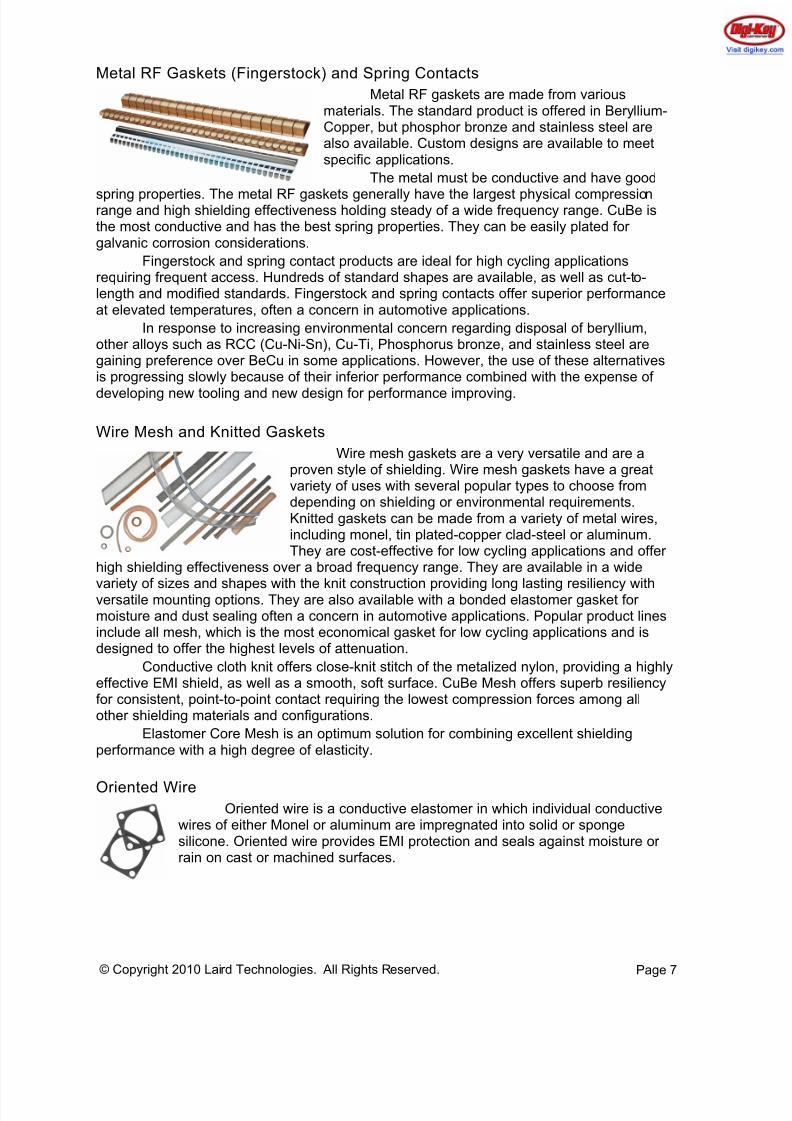
Metal RF Gaskets (Fingerstock) and Spring Contacts
Metal RF gaskets are made from variousmateria llium-ls. The standard product is offered in BeryCopper, but phosphor bronze and stainless steel arealso available. Custom designs are available to meetspecific applications.
The metal must be conductive and have good
spring nproperties. The metal RF gaskets generally have the largest physical compressiorange and high shielding effectiveness holding steady of a wide frequency range. CuBe isthe most conductive and has the best spring properties. They can be easily plated forgalvanic corrosion considerations.
Fingerstock and spring contact products are ideal for high cycling applicationsrequirin o-g frequent access. Hundreds of standard shapes are available, as well as cut-tlength and modified standards. Fingerstock and spring contacts offer superior performanceat elevated temperatures, often a concern in automotive applications.
In response to increasing environmental concern regarding disposal of beryllium,other alloys such as RCC (Cu-Ni-Sn), Cu-Ti, Phosphorus bronze, and stainless steel aregaining preference over BeCu in some applications. However, the use of these alternativesis progressing slowly because of their inferior performance combined with the expense of
developing new tooling and new design for performance improving.
Wire Mesh and Knitted Gaskets
Wire mesh gaskets are a very versatile and are aproven style of shielding. Wire mesh gaskets have a greatvariety of uses with several popular types to choose fromdepending on shielding or environmental requirements.Knitted gaskets can be made from a variety of metal wires,including monel, tin plated-copper clad-steel or aluminum.They are cost-effective for low cycling applications and offer
high shielding effectiveness over a broad frequency range. They are available in a wide
variety of sizes and shapes with the knit construction providing long lasting resiliency withversatile mounting options. They are also available with a bonded elastomer gasket formoisture and dust sealing often a concern in automotive applications. Popular product linesinclude all mesh, which is the most economical gasket for low cycling applications and isdesigned to offer the highest levels of attenuation.
Conductive cloth knit offers close-knit stitch of the metalized nylon, providing a highlyeffective EMI shield, as well as a smooth, soft surface. CuBe Mesh offers superb resiliencyfor consistent, point-to-point contact requiring the lowest compression forces among allother shielding materials and configurations.
Elastomer Core Mesh is an optimum solution for combining excellent shieldingperformance with a high degree of elasticity.
Oriented WireOriented wire is a conductive elastomer in which individual conductive
wires of either Monel or aluminum are impregnated into solid or spongesilicone. Oriented wire provides EMI protection and seals against moisture orrain on cast or machined surfaces.
8/10/2019 Laird Automotive EMI Shielding White Paper
http://slidepdf.com/reader/full/laird-automotive-emi-shielding-white-paper 8/14
Page 8© Copyright 2010 Laird Technologies. All Rights Reserved.
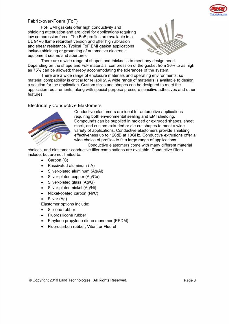
Fabric-over-Foam (FoF)
FoF EMI gaskets offer high conductivity andshielding attenuation and are ideal for applications requiringlow compression force. The FoF profiles are available in aUL 94V0 flame retardant version and offer high abrasionand shear resistance. Typical FoF EMI gasket applicationsinclude shielding or grounding of automotive electronic
equipment seams and apertures.There are a wide range of shapes and thickness to meet any design need.
Depending on the shape and FoF materials, compression of the gasket from 30% to as highas 75% can be allowed; thereby accommodating the tolerances of the system.
There are a wide range of enclosure materials and operating environments, somaterial compatibility is critical for reliability. A wide range of materials is available to designa solution for the application. Custom sizes and shapes can be designed to meet theapplication requirements, along with special purpose pressure sensitive adhesives and otherfeatures.
Electrically Conductive Elastomers
Conductive elastomers are ideal for automotive applicationsrequiring both environmental sealing and EMI shielding.Compounds can be supplied in molded or extruded shapes, sheetstock, and custom extruded or die-cut shapes to meet a widevariety of applications. Conductive elastomers provide shieldingeffectiveness up to 120dB at 10GHz. Conductive extrusions offer awide choice of profiles to fit a large range of applications.
Conductive elastomers come with many different materialchoices, and elastomer-conductive filler combinations are available. Conductive fillersinclude, but are not limited to:
• Carbon (C)
• Passivated aluminum (IA)
• Silver-plated aluminum (Ag/Al)• Silver-plated copper (Ag/Cu)
• Silver-plated glass (Ag/G)
• Silver-plated nickel (Ag/Ni)
• Nickel-coated carbon (Ni/C)
• Silver (Ag)
Elastomer options include:
• Silicone rubber
• Fluorosilicone rubber
• Ethylene propylene diene monomer (EPDM)
• Fluorocarbon rubber, Viton, or Fluorel
8/10/2019 Laird Automotive EMI Shielding White Paper
http://slidepdf.com/reader/full/laird-automotive-emi-shielding-white-paper 9/14
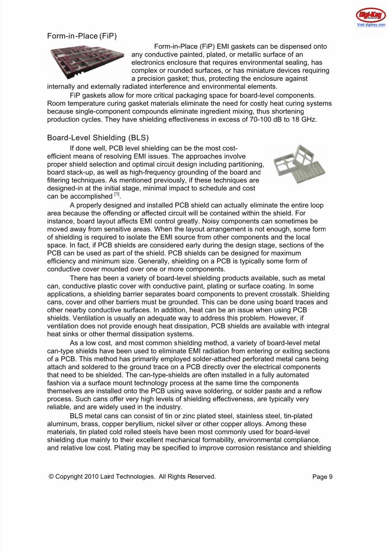
Form-in-Place (FiP)
Form-in-Place (FiP) EMI gaskets can be dispensed ontoany conductive painted, plated, or metallic surface of anelectronics enclosure that requires environmental sealing, hascomplex or rounded surfaces, or has miniature devices requiringa precision gasket; thus, protecting the enclosure against
internally and externally radiated interference and environmental elements.
FiP gaskets allow for more critical packaging space for board-level components.Room temperature curing gasket materials eliminate the need for costly heat curing systemsbecause single-component compounds eliminate ingredient mixing, thus shorteningproduction cycles. They have shielding effectiveness in excess of 70-100 dB to 18 GHz.
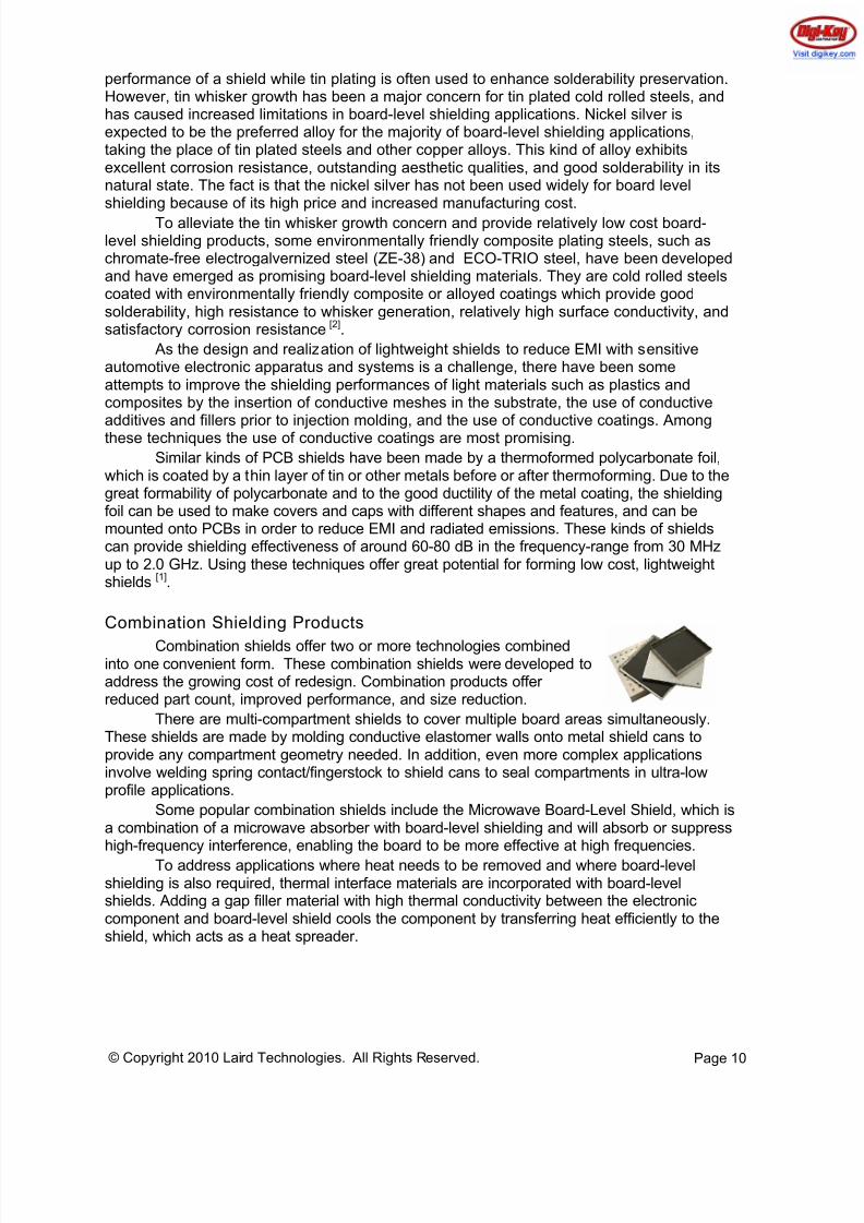
Board-Level Shielding (BLS)
If done well, PCB level shielding can be the most cost-efficient means of resolving EMI issues. The approaches involveproper shield selection and optimal circuit design including partitioning,board stack-up, as well as high-frequency grounding of the board andfiltering techniques. As mentioned previously, if these techniques aredesigned-in at the initial stage, minimal impact to schedule and costcan be accomplished [1].
A properly designed and installed PCB shield can actually eliminate the entire looparea because the offending or affected circuit will be contained within the shield. Forinstance, board layout affects EMI control greatly. Noisy components can sometimes bemoved away from sensitive areas. When the layout arrangement is not enough, some formof shielding is required to isolate the EMI source from other components and the localspace. In fact, if PCB shields are considered early during the design stage, sections of thePCB can be used as part of the shield. PCB shields can be designed for maximumefficiency and minimum size. Generally, shielding on a PCB is typically some form ofconductive cover mounted over one or more components.
There has been a variety of board-level shielding products available, such as metal
can, conductive plastic cover with conductive paint, plating or surface coating. In someapplications, a shielding barrier separates board components to prevent crosstalk. Shieldingcans, cover and other barriers must be grounded. This can be done using board traces andother nearby conductive surfaces. In addition, heat can be an issue when using PCBshields. Ventilation is usually an adequate way to address this problem. However, ifventilation does not provide enough heat dissipation, PCB shields are available with integralheat sinks or other thermal dissipation systems.
As a low cost, and most common shielding method, a variety of board-level metalcan-type shields have been used to eliminate EMI radiation from entering or exiting sectionsof a PCB. This method has primarily employed solder-attached perforated metal cans beingattach and soldered to the ground trace on a PCB directly over the electrical componentsthat need to be shielded. The can-type-shields are often installed in a fully automated
fashion via a surface mount technology process at the same time the componentsthemselves are installed onto the PCB using wave soldering, or solder paste and a reflowprocess. Such cans offer very high levels of shielding effectiveness, are typically veryreliable, and are widely used in the industry.
BLS metal cans can consist of tin or zinc plated steel, stainless steel, tin-platedaluminum, brass, copper beryllium, nickel silver or other copper alloys. Among thesematerials, tin plated cold rolled steels have been most commonly used for board-levelshielding due mainly to their excellent mechanical formability, environmental compliance,and relative low cost. Plating may be specified to improve corrosion resistance and shielding
Page 9© Copyright 2010 Laird Technologies. All Rights Reserved.
8/10/2019 Laird Automotive EMI Shielding White Paper
http://slidepdf.com/reader/full/laird-automotive-emi-shielding-white-paper 10/14
performance of a shield while tin plating is often used to enhance solderability preservation.However, tin whisker growth has been a major concern for tin plated cold rolled steels, andhas caused increased limitations in board-level shielding applications. Nickel silver isexpected to be the preferred alloy for the majority of board-level shielding applications,taking the place of tin plated steels and other copper alloys. This kind of alloy exhibitsexcellent corrosion resistance, outstanding aesthetic qualities, and good solderability in itsnatural state. The fact is that the nickel silver has not been used widely for board levelshielding because of its high price and increased manufacturing cost.
To alleviate the tin whisker growth concern and provide relatively low cost board-level shielding products, some environmentally friendly composite plating steels, such aschromate-free electrogalvernized steel (ZE-38) and ECO-TRIO steel, have been developedand have emerged as promising board-level shielding materials. They are cold rolled steelscoated with environmentally friendly composite or alloyed coatings which provide goodsolderability, high resistance to whisker generation, relatively high surface conductivity, andsatisfactory corrosion resistance [2].
As the design and realization of lightweight shields to reduce EMI with sensitiveautomotive electronic apparatus and systems is a challenge, there have been someattempts to improve the shielding performances of light materials such as plastics andcomposites by the insertion of conductive meshes in the substrate, the use of conductiveadditives and fillers prior to injection molding, and the use of conductive coatings. Amongthese techniques the use of conductive coatings are most promising.
Similar kinds of PCB shields have been made by a thermoformed polycarbonate foil,which is coated by a thin layer of tin or other metals before or after thermoforming. Due to thegreat formability of polycarbonate and to the good ductility of the metal coating, the shieldingfoil can be used to make covers and caps with different shapes and features, and can bemounted onto PCBs in order to reduce EMI and radiated emissions. These kinds of shieldscan provide shielding effectiveness of around 60-80 dB in the frequency-range from 30 MHzup to 2.0 GHz. Using these techniques offer great potential for forming low cost, lightweightshields [1].
Combination Shielding Products
Combination shields offer two or more technologies combinedinto one convenient form. These combination shields were developed toaddress the growing cost of redesign. Combination products offerreduced part count, improved performance, and size reduction.
There are multi-compartment shields to cover multiple board areas simultaneously.These shields are made by molding conductive elastomer walls onto metal shield cans toprovide any compartment geometry needed. In addition, even more complex applicationsinvolve welding spring contact/fingerstock to shield cans to seal compartments in ultra-lowprofile applications.
Some popular combination shields include the Microwave Board-Level Shield, which isa combination of a microwave absorber with board-level shielding and will absorb or suppresshigh-frequency interference, enabling the board to be more effective at high frequencies.
To address applications where heat needs to be removed and where board-levelshielding is also required, thermal interface materials are incorporated with board-levelshields. Adding a gap filler material with high thermal conductivity between the electroniccomponent and board-level shield cools the component by transferring heat efficiently to theshield, which acts as a heat spreader.
Page 10© Copyright 2010 Laird Technologies. All Rights Reserved.
8/10/2019 Laird Automotive EMI Shielding White Paper
http://slidepdf.com/reader/full/laird-automotive-emi-shielding-white-paper 11/14
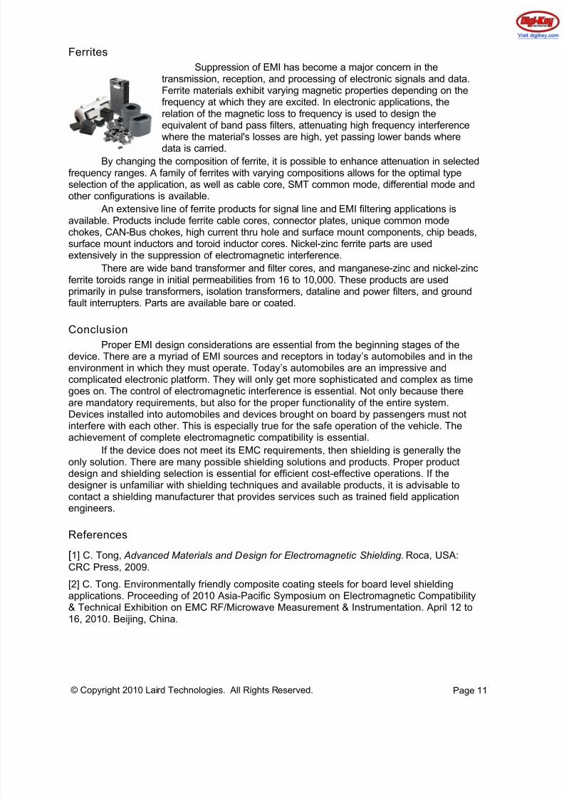
Ferrites
Suppression of EMI has become a major concern in thetransmission, reception, and processing of electronic signals and data.Ferrite materials exhibit varying magnetic properties depending on thefrequency at which they are excited. In electronic applications, therelation of the magnetic loss to frequency is used to design theequivalent of band pass filters, attenuating high frequency interference
where the material's losses are high, yet passing lower bands wheredata is carried.
By changing the composition of ferrite, it is possible to enhance attenuation in selectedfrequency ranges. A family of ferrites with varying compositions allows for the optimal typeselection of the application, as well as cable core, SMT common mode, differential mode andother configurations is available.
An extensive line of ferrite products for signal line and EMI filtering applications isavailable. Products include ferrite cable cores, connector plates, unique common modechokes, CAN-Bus chokes, high current thru hole and surface mount components, chip beads,surface mount inductors and toroid inductor cores. Nickel-zinc ferrite parts are usedextensively in the suppression of electromagnetic interference.
There are wide band transformer and filter cores, and manganese-zinc and nickel-zinc
ferrite toroids range in initial permeabilities from 16 to 10,000. These products are usedprimarily in pulse transformers, isolation transformers, dataline and power filters, and groundfault interrupters. Parts are available bare or coated.
Conclusion
Proper EMI design considerations are essential from the beginning stages of thedevice. There are a myriad of EMI sources and receptors in today’s automobiles and in theenvironment in which they must operate. Today’s automobiles are an impressive andcomplicated electronic platform. They will only get more sophisticated and complex as timegoes on. The control of electromagnetic interference is essential. Not only because thereare mandatory requirements, but also for the proper functionality of the entire system.
Devices installed into automobiles and devices brought on board by passengers must notinterfere with each other. This is especially true for the safe operation of the vehicle. Theachievement of complete electromagnetic compatibility is essential.
If the device does not meet its EMC requirements, then shielding is generally theonly solution. There are many possible shielding solutions and products. Proper productdesign and shielding selection is essential for efficient cost-effective operations. If thedesigner is unfamiliar with shielding techniques and available products, it is advisable tocontact a shielding manufacturer that provides services such as trained field applicationengineers.
References
[1] C. Tong, Advanced Materials and Design for Electromagnetic Shielding. Roca, USA:CRC Press, 2009.
[2] C. Tong. Environmentally friendly composite coating steels for board level shieldingapplications. Proceeding of 2010 Asia-Pacific Symposium on Electromagnetic Compatibility& Technical Exhibition on EMC RF/Microwave Measurement & Instrumentation. April 12 to16, 2010. Beijing, China.
Page 11© Copyright 2010 Laird Technologies. All Rights Reserved.
8/10/2019 Laird Automotive EMI Shielding White Paper
http://slidepdf.com/reader/full/laird-automotive-emi-shielding-white-paper 12/14
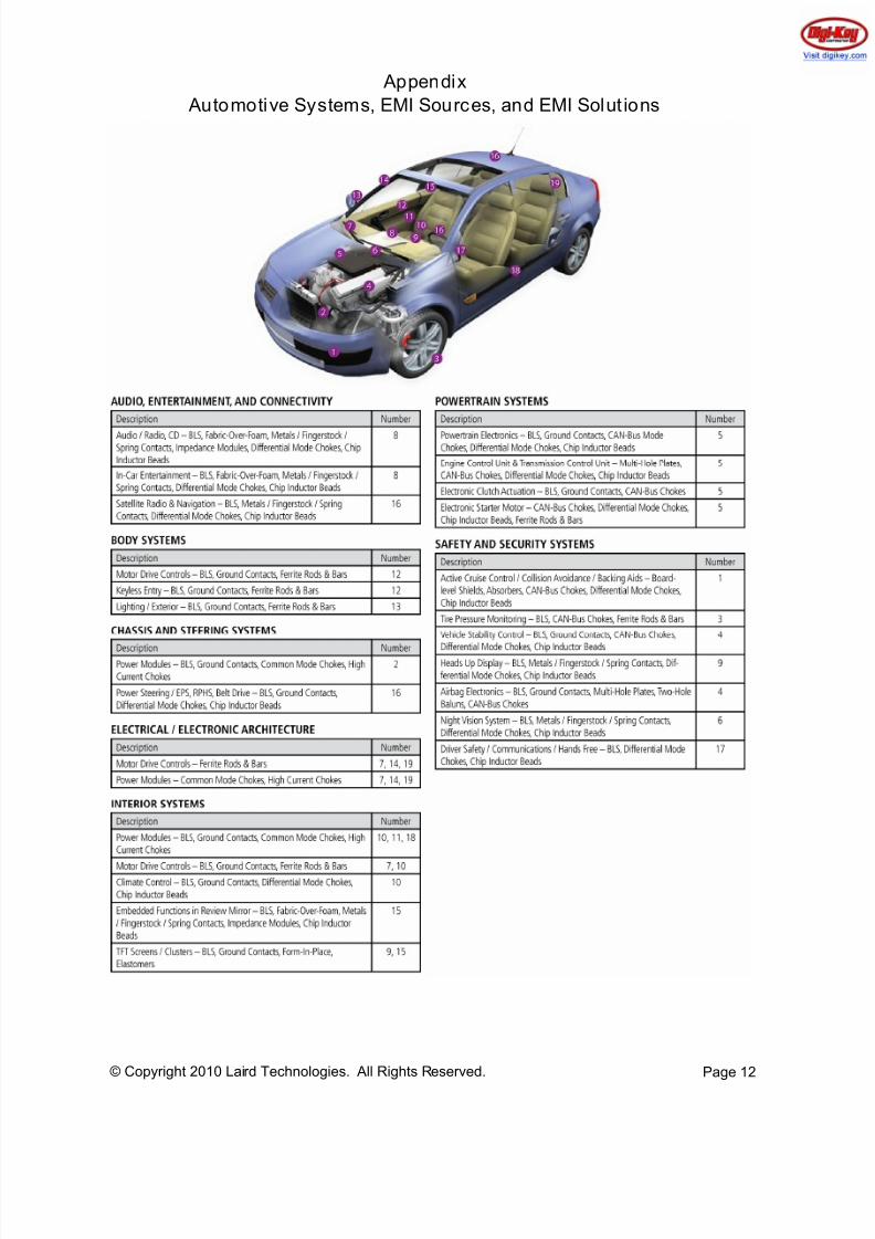
Appendix
Automotive Systems, EMI Sources, and EMI Solut ions
Page 12© Copyright 2010 Laird Technologies. All Rights Reserved.
8/10/2019 Laird Automotive EMI Shielding White Paper
http://slidepdf.com/reader/full/laird-automotive-emi-shielding-white-paper 13/14
Page 13© Copyright 2010 Laird Technologies. All Rights Reserved.
About the Authors
John Noto has been with Laird Technologies for 10 years. He has a strong background inoperations management, including the introduction of major EMI metals facilities in China,Czech Republic, and Mexico. Mr. Noto was formally the Inside Sales Manager for LairdTechnologies’ Pennsylvania facility. He is currently managing all EMI metals product linesfor the Americas region. He has a BS in Business Management as well as an AS inMechanical Design.
Gary Fenical has been with Laird Technologies for 26 years. He is a specialist in RFshielded enclosures and has been responsible for the design and / or measurement andquality control of hundreds of large-scale shielded enclosures, as well as a number ofshielded equipment cabinets and housings. He was instrumental in the design andconstruction of Laird Technologies' state-of-the-art World Compliance Centers. Mr. Fenicalhas authored many articles on EMC Requirements for Medical Devices, Mutual Recognition Agreements and Guidelines; meeting the essential requirements of the EU EMC Directive.He has also authored several seminars on the EU EMC Directive, International Compliance,and Designing for EMC and EMC Requirements for Medical Devices which have been presented worldwide. He holds the patent for the invention of heat-treated beryllium-copperknitted wire mesh gaskets.
Colin Tong joined Laird technologies in 2006 as a materials specialist for the PerformanceMaterials Division. He has been responsible for the management of metal and EMI testinglabs, involvement in the development of EMI shielding materials, and supporting themanufacturing process, quality assurance, and technical service with engineeringresponsibility for EMI shielding products. In addition, he has almost 20 years of experiencein research and development, testing and characterization, component design and processing of advanced materials, metallurgical products, thermal management of electronic packaging, as well as electromagnetic interference shields. He holds a Ph.D. in MaterialsScience and Engineering. His research & development activities and industrial practiceshave resulted in more than 30 papers, several patents, and two books. Dr. Tong is amember of the TMS, ASME, and ASM International. He received the Henry Marion Howe
Medal from ASM international for his contribution to research and development on advancedcomposite materials in 1999.
About Laird Technologies, Inc:
Laird Technologies designs and manufactures customized, performance-critical products forwireless and other advanced electronics applications.
The company is a global market leader in the design and supply of electromagneticinterference (EMI) shielding, thermal management products, mechanical actuation systems,signal integrity components, and wireless antennae solutions, as well as radio frequency(RF) modules and systems.
Custom products are supplied to all sectors of the electronics industry including the handset,telecommunications, data transfer and information technology, automotive, aerospace,defense, consumer, medical, and industrial markets.
Laird Technologies, a unit of Laird PLC, employs over 10,000 employees in more than 39facilities located in 13 countries.
8/10/2019 Laird Automotive EMI Shielding White Paper
http://slidepdf.com/reader/full/laird-automotive-emi-shielding-white-paper 14/14
Page 14© Copyright 2010 Laird Technologies. All Rights Reserved.
Trademarks
© 2010 All rights reserved. Laird Technologies and its logo are trademarks of LairdTechnologies, Inc. Other products, logos, and company names mentioned herein, may betrademarks of their respective owners.