chomerics emi shielding handbook
TRANSCRIPT
Seals
Chomerics is a division of theSeal Group of the ParkerHannifin Corporation. Parker
Seal is one of the world’s largest and most experi-enced manufacturers of elastomer and other sealingand shielding devices.
Chomer ics is the world’s largest
manufacturer of EMI (electromagnetic
interference) shielding materials. Our
strengths are service, experience,
technology, and unparalleled design
capabilities.
Since 1961, Chomerics has been the
primary force in the development and
application of conductive elastomer
technology in extruded, molded and
RTV compound forms and, more recently,
Form-in-Place gasketing. Our other
products include: metal EMI gasketing
• spring finger gaskets • EMI cable
shielding • conductive coatings and
adhesives • shielding laminates and foil
tapes • shielded vents and windows.
We also manufacture an innovative line
of thermal interface materials.
Chomerics products have been
designed into thousands of applications:
telecommunications systems, from
cellular handsets to base stations and
switch gear; information systems, from
laptops to mainframes; cables and
connectors; process measurement and
control equipment; medical devices;
military and aerospace applications...
and many more.
Our comprehensive compliance
and safety testing facilities provide
us constant exposure to real-world
problems. We meet shielding challenges
head on, and respond with effective
solutions.leader in EMI shielding technology
ChomericsDiv. of Parker Hannifin77 Dragon CourtWoburn, MA 01888-4014TEL: +(1) 781-935-4850FAX: +(1) 781-933-4318
Parker Hannifin PLCChomerics EuropeParkway, Globe Park EstateMarlow, Bucks., SL7 1YB, EnglandTEL: +(44) 1628 404000FAX: +(44) 1628 404090
PRINTED IN U.S.A. NOVEMBER 2000 5501
www.chomerics.com
Parker Hannifin Asia Pacific GroupChomerics Sales Department8/F, Kin Yip Plaza9 Cheung Yee StreetCheung Sha WanKowloon, Hong KongTEL: +(852) 2 428 8008FAX: +(852) 2 423 8253
9002CERTIFIED
Parker Hannifin Ind. e Com.LtdaSeals DivisionVia Anhanguera, KM 25,3-Perus05276-977-São Paulo-SP, BrazilTEL: +(55) 11 3917 1099FAX: +(55) 11 3917 0817
9001CERTIFIED
Seals
Seals
EMI ShieldingEngineering HandbookEMI ShieldingEngineering Handbook
EM
I Shie
ldin
g E
ngin
eerin
g H
andbook
EM
I Shie
ldin
g E
ngin
eerin
g H
andbook

Chomer ics ’ commitment to
the EMI shielding industry is obvious
from our investment in state-of-the-art
manufacturing and testing facilities, and
by our deployment of sales and technical
support personnel across four continents.
The Company is headquartered in
Woburn, Massachusetts along the “high
technology” Route 128 belt surrounding
Boston. Conductive elastomers, conduc-
tive compounds and knitted wire mesh
products are manufactured within this
technology center. EMC and Safety Test
Services also located here include
NAVLAP accredited testing facilities.
Engineered shielding laminates are
produced at Chomerics’ Hudson, New
Hampshire plant. Located only 30 min-
utes from our technology center, our
Laminates technical staff works closely
with Woburn application and test special-
ists on complex EMI shielding problems.
In Europe, Chomerics is headquartered
in Marlow, England (near London), with
manufacturing facilities, including Cho-
Form ® gasket application lines, as well as
applications specialists.
Far East manufacturing and
sales support are provided
through Parker Hannifin’s Asia
Pacific subsidiaries in Hong Kong,
Taiwan, China, Japan, Korea and
Singapore.
In South America, sales support
is provided through Parker
Chomerics facilities in São Paulo,
Brazil.
Woburn, Massachusetts
Hudson, New Hampshire
Marlow, England
Seals
NOTICE: The information contained herein is to the best of our knowledge true and accurate. However , since the varied conditionsof potential use are beyond our control, all recommendations or suggestions are presented without guarantee or responsibility onour part and users should make their own tests to determine the suitability of our products in any specific situation. This prod-uct is sold without warranty, either expressed or implied, of fitness for a particular purpose or otherwise, except that this prod-uct shall be of standard quality, and except to the extent otherwise stated on Chomerics’ invoice, quotation, or order acknowl-edgement. We disclaim any and all liability incurred in connection with the use of information contained herein, or other wise. Allrisks of such are assumed by the user . Furthermore, nothing contained herein shall be construed as a recommendation to useany process or to manufacture or to use any product in conflict with existing or future patents covering any product or materia lor its use. The items described in this document are hereby offered for sale by Parker Hannifin Corporation, its subsidiaries or itsauthorized distributors. This offer and its acceptance are governed by the provisions stated on the document entitled “Offer ofSale,” available from Chomerics on request.
At Chomerics, we strive to provide our customerswith the best EMI shielding products and services at the low-est cost, when and where you need them.
The company’s growth and the expansion of the productsand services provided to our customers are reflected in thisEMI/EMC Engineering Handbook. The complete Handbookand additional collateral information may be accessed at ourwebsite, www.chomerics.com.
Chomerics is truly a global supplier. We now have salesand applications engineering services available in NorthAmerica, South America, Europe, and Asia. Local manufactur-ing sites are in operation in most major markets, and more will follow.
Chomerics’ growth has been driven by the wireless communications industry, not only resulting in new productsand services, but also multi-level, global relationships withcustomers and other companies in the supply chain. OurContract Manufacturing and Supply Chain Managementservices (pages 6-7) as well as the automated EMI shieldingtechnologies and high-speed conductive coating operationsdetailed in the SHIELDING SOLUTIONS FOR WIRELESS APPLICATIONS
section (pages 9-26), are available to all Chomerics customers.
Through design support that includes extensive use of simulations, finite element analysis, and other design tools,we continue to assist customers in choosing the right solutionsfor their applications. Our Applications Engineering organiza-tion is available at all times to discuss your needs.
General OrderingInformationSALES FORCE – Chomerics’Sales Offices are supplementedby Territory Sales Managersthroughout North America,Europe, Asia and South America.These specialists are able to provide technical information,design assistance, pricing esti-mates and samples. To obtainthe name of your nearestChomeric’s Sales Manager, contact our Sales Offices at the locations on the rear cover,or consult our website:www.chomerics.com
AUTHORIZED DISTRIBU-TORS, FABRICATORS ANDAGENTS – More than 100global locations are listed onthe final pages of this Handbook.
PRICES AND TERMS–Prices and terms for all productswill be quoted on request.Tooling and/or set-up chargesfor custom parts will be speci-fied in the quotation.
PACKAGING – At customerrequest, shipments are pack-aged using best commercialpractices.
FOB ORIGIN
U.S. FEDERALSUPPLIER CODEFSCM 18565Massachuse t t s• Conductive Elastomers• Adhesives, Sealants, Coatings• Wire Mesh Gaskets• Shielded Vents and Windows• Cable Shielding• Applications Engineering• EMC and Safety Test Services
FSCM 8W262New Hampsh i re• Engineered Laminates• Conductive Tapes• Shielded Cable Jackets• Thermal Interface Materials

COST-EFFECTIVE SOLUTIONS FOR MAJOR APPLICATIONS. . . . . . . . . .2
Wireless handset shielding and grounding....2
Outdoor enclosure shielding............................3
Indoor cabinet shielding...................................4
Information Technology shielding and grounding...................................................5
CONTRACT MANUFACTURING & SUPPLY CHAIN MANAGEMENT. . . . . . . 6ENGINEERING SUPPORT. . . . . . . . . . . . . .8
Design, Finite Element Analysis (FEA),Seminars and R&D
SHIELDING SOLUTIONS FOR WIRELESS COMMUNICATIONS. . . . . . . 9
Introduction...................................................10
CHO-SHIELD® EMI shielding covers..........11
CHO-VER SHIELDTM shielding covers.........12
EMI shielding/grounding spacer gaskets.....................................................14
Automated conductive coating ofplastic housings....................................... 17
Cho-Form® robotically dispensedconductive elastomer technology............18
CONDUCTIVE ELASTOMERGASKETS . . . . . . . . . . . . . . . . . . . . . . . . . . . . .27
CHO-SEAL® & CHO-SIL®
conductive elastomers.............................28
Selection Guide........................................... 30
Material specifications.................................32
Introduction to elastomer extrusions.......... 35
Ordering extrusions..................................... 38
Standard extrusions.....................................41
Custom extrusions...................................... 48
Co-extruded strips.......................................55
Sheet stock and die-cut parts.....................58
Molded shapes............................................61
Molded D- & O-rings................................... 63
Flat washers.................................................66
Waveguide gaskets..................................... 67
Connector gaskets.......................................72
Reinforced conductive elastomer seals......76
Molded-in-place cover seals.......................77
Performance data........................................80
Volume resistivity measurement..................86
Part number index....................................... 87
SOFT-SHIELD® LOW CLOSURE FORCE, FOAM CORE EMI GASKETS . . . . . . . . . . . . . . . . . . . . . . . . . . . . .91
Applications and comparative performance.............................................92
ContentsSOFT-SHIELD 5000 series
(conductive jacket over foam).................93
SOFT-SHIELD 4000 series (foil/fabric over foam).............................. 98
SOFT-SHIELD 2000 series (conductive yarn over foam) ..................101
SOFT-SHIELD 1000 series (knitted wire over foam) ........................103
METAL EMI GASKETS, CLIP-ON GASKETS & FINGERSTOCK.. . . . . . .105
Material specifications...............................106
MESH STRIPTM all metal gaskets................107
MESH STRIPTM with elastomer core...........109
SPRINGMESH® highly resilient gaskets...................................................111
COMBO® STRIP and COMBO®
gaskets...................................................112
SHIELDMESHTM compressed mesh gaskets...................................................115
Frame gaskets and strips..........................116
POLASHEET® & POLASTRIP®
composite gasketing/weather seal.......118
METALASTIC® & PORCUPINE METALASTIC® gasketing with pressure seal............................................121
Connector gaskets.....................................122
METALKLIP® clip-on gaskets....................123
Performance data......................................124
SPRING-LINE® Be-Cu fingerstock............126
SPRING-LINE® card cage gaskets...........131
SPRING-LINE® D-connector gaskets........132
CONDUCTIVE COMPOUNDS. . . . . . . .133Typical Applications...................................134
CHO-BOND® conductive adhesives.........135
CHO-BOND® conductive sealants & caulks..................................................138
CHO-SHIELD® conductive coatings.........140
CHO-FLEX® conductive coatings & inks......................................................142
ENGINEERED LAMINATES & GROUNDING PRODUCTS . . . . . . . . . . 143
CHO-MASK® II foil tape with peel-off mask.........................................144
CHO-FOIL® & CHO-FABTM EMI shielding tapes......................................146
EMI shielding tapes kit...............................149
EMI shielding laminates.............................150
Missile canister seals.................................152
CHO-STRAP® insulated ground strap...... 153
Conductive grounding tabs.......................154
CHO-BUTTONTM grounding contacts........156
EMI SHIELDED VENTS . . . . . . . . . . . . . .157STREAMSHIELDTM shielded
vent/airflow panels..................................158
CHO-CELL® shielded vent panels..............161
OMNI CELL® and SHIELD CELL®
shielded vent panels...............................162
Steel & brass honeycomb shielded vents.........................................164
SLIMVENTTM space-saving vent panels......................................................165
VIP® shielded air filters................................165
SHIELDSCREEN® shielded air filters..........166
Common parts table....................................167
Performance data........................................168
EMI SHIELDED WINDOWS & CONTRASTENHANCEMENT FILTERS . . . . . . . . . . . .169
EMI-CLARETM GP 70 shielded windows.....170
WIN-SHIELDTM optical products..................172
WIN-SHIELDTM AgF8 conductive film.........174
CABLE SHIELDING. . . . . . . . . . . . . . . . . . 175CHO-SORB® EMI ferrites............................176
CHO-DROP® EMI absorbers......................183
ZIP-EX-2® zippered cable shielding...........184
CHO-SHRINK® heat shrinkable shielding, connector boots, transitions, & assembly...........................186
CHO-JAC® flat cable EMI shield................189
SHIELD WRAPTM wire mesh tape...............190
EMI SHIELDING THEORY & GASKET DESIGN GUIDE. . . . . . . . . . . .191
Theory of shielding and gasketing............192
Conductive elastomer design....................196
Gasket junction...........................................196
Corrosion.................................................... 198
Seal cross section..................................... 202
General tolerances.................................... 204
Gasket mounting choices.......................... 205
Fastener requirements............................... 206
Solid-O gasket-in-a-groove design........... 209
Mesh EMI gasket selection....................... 214
Glossary of terms...................................... 218
Part number cross-reference.................... 220
GLOBAL COMPLIANCE TESTING. . .222EMI/EMC/Safety Testing and Design
THERMAL MANAGEMENT PRODUCTS OVERVIEW. . . . . . . . . . . . .224
AUTHORIZED DISTRIBUTORS & FABRICATORS WORLDWIDE . . . . . . .226
Visit our website w w w.chomer ics .com
For engineering design assistance or toorder any Chomerics product, call:
Europe +(44) 1628 404000Asia Pacific +(852) 2 428 8008South America +(55) 11 3917 1099 North America +(1) 781-935-4850
Cost-Effective Solutions forMajor Applications
US Headquarters TEL +(1) 781-935-4850 FAX +(1) 781-933-4318 • www.chomerics.comEurope TEL +(44) 1628 404000 FAX +(44) 1628 404090
Asia Pacific TEL +(852) 2 428 8008 FAX +(852) 2 423 8253South America TEL +(55) 11 3917 1099 FAX +(55) 11 3917 0817
32US Headquarters TEL +(1) 781-935-4850 FAX +(1) 781-933-4318 • www.chomerics.com
Europe TEL +(44) 1628 404000 FAX +(44) 1628 404090Asia Pacific TEL +(852) 2 428 8008 FAX +(852) 2 423 8253
South America TEL +(55) 11 3917 1099 FAX +(55) 11 3917 0817
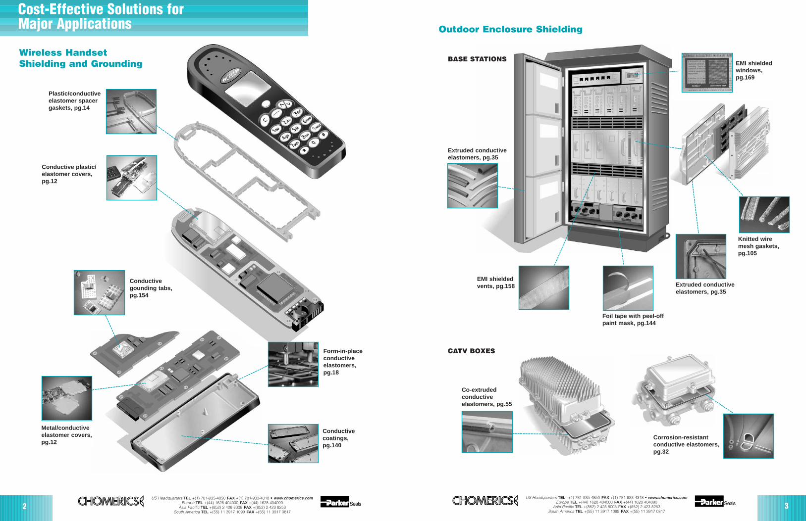
Wireless HandsetShielding and Grounding
Plastic/conductiveelastomer spacergaskets, pg.14
Conductive plastic/elastomer covers,pg.12
Conductivegounding tabs,pg.154
Metal/conductiveelastomer covers,pg.12
Form-in-placeconductiveelastomers,pg.18
Conductivecoatings,pg.140
Outdoor Enclosure Shielding
BASE STATIONS
CATV BOXES
Extruded conductiveelastomers, pg.35
EMI shieldedvents, pg.158
Foil tape with peel-offpaint mask, pg.144
Extruded conductive elastomers, pg.35
Knitted wire mesh gaskets,pg.105
EMI shielded windows,pg.169
Co-extrudedconductiveelastomers, pg.55
Corrosion-resistantconductive elastomers,pg.32
US Headquarters TEL +(1) 781-935-4850 FAX +(1) 781-933-4318 • www.chomerics.comEurope TEL +(44) 1628 404000 FAX +(44) 1628 404090
Asia Pacific TEL +(852) 2 428 8008 FAX +(852) 2 423 8253South America TEL +(55) 11 3917 1099 FAX +(55) 11 3917 0817
54US Headquarters TEL +(1) 781-935-4850 FAX +(1) 781-933-4318 • www.chomerics.com
Europe TEL +(44) 1628 404000 FAX +(44) 1628 404090Asia Pacific TEL +(852) 2 428 8008 FAX +(852) 2 423 8253
South America TEL +(55) 11 3917 1099 FAX +(55) 11 3917 0817
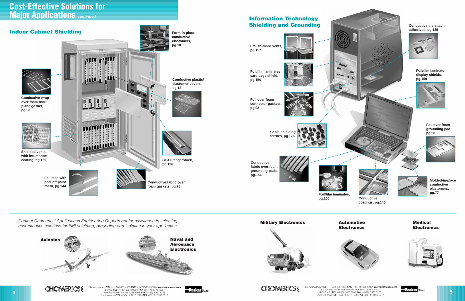
Cost-Effective Solutions forMajor Applications continued
Form-in-placeconductiveelastomers,pg.18
Indoor Cabinet Shielding
Conductive plastic/elastomer covers pg.12
Be-Cu fingerstock,pg.126
Conductive fabric overfoam gaskets, pg.93
Conductive wrapover foam back-plane gasket,pg.98
Shielded ventswith intumesentcoating, pg.159
Foil tape withpeel-off paint mask, pg.144
EMI shielded vents,pg.157
Foil/film laminatescard cage shield,pg.150
Foil over foamconnector gaskets,pg.98
Cable shieldingferrites, pg.176
Conductivecoatings, pg.140
Foil/film laminates,pg.150
Conductivefabric over foamgrounding pads,pg.154
Molded-in-placeconductiveelastomers,pg.77
Foil over foamgrounding padpg.98
Foil/film laminatedisplay shields, pg.150
Conductive die attachadhesives, pg.135
Contact Chomerics’ Applications Engineering Department for assistance in selectingcost-effective solutions for EMI shielding, grounding and isolation in your application.
Avionics Naval and AerospaceElectronics
Military Electronics
Information TechnologyShielding and Grounding
Automotive Electronics
Medical Electronics

Contract Manufacturing and SupplyChain Management
Simplify the supply logistics and upgrade the quality ofEMI shielded housings and enclosuresMore than ever, high-volume electronic device and enclo-sure manufacturers seek to integrate production process-es to the greatest extent possible. For EMI shieldedhousings and enclosures, choosing Chomerics as thelead vendor to manage the overall supply chain greatlystreamlines production and scheduling. It also brings significant cost and quality benefits:
Production times shrinkEliminate difficult logistics, excessive transportation costsand time lost in moving parts from a housing or enclosuremanufacturer to a plating or conductive coating supplier,to an EMI gasketing operation, to a part assembler andfinally to the OEM. Instead, Chomerics can handle mostsecondary operations at one location, trimming time andcost significantly.
Costs are kept under controlWith fewer suppliers to manage, and inventory coordinat-ed by Chomerics, fewer in-house resources are requiredto oversee production. Inventory expense is minimizedand costly production downtime is avoided.
Designs are optimizedWhen Chomerics interfaces with and manages housingsuppliers, common preventable design faults that hinderEMI shielding application are avoided. Part tolerancesappropriate for maximum throughput are ensured.
6US Headquarters TEL +(1) 781-935-4850 FAX +(1) 781-933-4318 • www.chomerics.com
Europe TEL +(44) 1628 404000 FAX +(44) 1628 404090Asia Pacific TEL +(852) 2 428 8008 FAX +(852) 2 423 8253
South America TEL +(55) 11 3917 1099 FAX +(55) 11 3917 0817
Accountability is maximizedExcuses and fingerpointing are eliminated whenChomerics oversees the supply chain and producescomplete assemblies to specifications that set perform-ance and quality criteria. Rather than dealing with multiple sources, you negotiate delivery times, toolingcost and price with a single vendor.
International application capabilitiesbring these services closerChomerics operates manufacturing facilities in a grow-ing number of locations around the world, providing ourcustomers with local sales support, quality support andcustomer service.
Woburn, Massachusetts, USAHudson and Dover, New Hampshire, USALancaster, New York, USASanta Clara, California, USAGuadalajara, MexicoMarlow, Bucks, United KingdomMadrid, SpainOldenburg, GermanySão Paulo, BrazilShanghai, ChinaTianjin, China Osaka, Japan
As production volumes warrant, Chomerics is pleasedto evaluate the feasibility of establishing additonal appli-cation sites at or near our customers’ manufacturinglocations.

7
Provides Full-Service Contract Manufacturing and Consignment Inventory• purchases all sub-components• performs value-added conductive coating, automated EMI
gasketing, manual gasket attachment, shielding laminate, window or honeycomb installation, etc.
• completes secondary assembly operations in-house• distributes parts to customer locations globally• establishes consignment inventories as needed
Develops Suppliers• evaluates and recommends suppliers for castings, injection
molded plastic, and electrical components • implements customers’ quality standards up and down the
supply chain• conducts first article evaluations with reports• ensures compliance with customer part approval process
Safely Manages Design Change• coordinates engineering change orders (ECO)• implements change in a planned process• oversees system and supplier-wide implementation• ensures that suppliers’ processes can support change(s)• controls introduction of change(s) into the supply chain, ensuring
traceability in all parts
Facilitates Resolution of all Quality Issues• establishes agreed-upon visual criteria, testing and inspection
techniques• ensures supplier calibration in periodic review meetings and
scheduled joint conferences with all suppliers in the chain • provides ongoing statistical process control of all suppliers and
processes, shared with every member• maintains documentation that prevents miscommunication
Manages Inventory• uses forecasting to ensure cost-effective product phase-out
without excessive final inventory• secures just-in-time deliveries throughout the supply chain,
including to our customer
Designs Specialized Packaging • develops compartmentalized plastic or corrugated paper
packaging needed to avoid scratches or other cosmetic injuries to parts
As Lead Supplier, Chomerics...
Chomerics manages the logistics of supplying high-volume, EMI shielded housings for majortelecommunications clients. In one example, casthousings originate with three vendors on two continents. After plating, they converge at our manufacturing location for automated EMI gasketingand contract subassembly operations, and are thenshipped to customer destinations in the US, Braziland Mexico for end-product manufacture.
A full array of contract manufacturing capabilitiesincludes• snap-on and mechanical press-fit of components• affixing components with adhesives• installing laminates• installing ground pads• insertion of threaded elements• ultrasonic welding• cosmetic painting• labeling ...efficiently performed at Chomerics’ automated EMIgasketing locations to eliminate unnecessary parttransport, handling and lost time.
Chomerics is ready to help you streamline the purchase and production ofshielding housings and enclosures. Call today to explore the possibilities.
US Headquarters TEL +(1) 781-935-4850 FAX +(1) 781-933-4318 • www.chomerics.comEurope TEL +(44) 1628 404000 FAX +(44) 1628 404090
Asia Pacific TEL +(852) 2 428 8008 FAX +(852) 2 423 8253South America TEL +(55) 11 3917 1099 FAX +(55) 11 3917 0817
Design ServicesApplications Engineering
Engineers confronted by EMIproblems frequently have too narrowa focus, or limited EMI experience,which can lead to ineffective EMIdesigns. That typically means extracost in retrofits, “brute force” shield-ing, and repetitive EMI testing.Chomerics can offer you two options:1) contact us for an EMI design con-sultation prior to reaching the proto-type stage, or2) contact us to arrange a technicalseminar. With either choice, you willreceive the help needed to avoidproblems in the design stage andavoid costly retrofits and repetitivetesting.
If you’re in touch with Chomericsbefore the prototype stage, we’ll opti-mize the housing design using CADand modeling to achieve the mostcost-effective methods of EMIsuppression. Or, if your system isalready in production, we’ll optimizethe EMI design within existing con-straints. With thousands of successfulapplications behind us, you can beassured of meeting system EMI spec-ifications.
Our understanding of the vari-ables involved in most EMI shieldingproblems enables us to direct elec-tronic packaging designers to themost cost-effective answer to anygiven set of application require-ments. Our “octane” product con-cept allows selections to be made onthe basis of both performanceand cost. Pre-production samplescan be produced for evaluation inprototype systems.
ENGINEERING SUPPORT
Seminars & R&D
Finite Element Analysis (FEA)As the premier manufacturer of
sophisticated conductive elastomerseals, Chomerics offers its customersthe dramatic time- and cost-savingbenefits of Finite Element Analysis(FEA). This advanced computer sim-ulation technology is employed topredict the behavior characteristicsof EMI gasket designs, bypassingthe development and trial-and-errortesting of successive prototypes.
FEA will not only confirm that aproposed design will perform asexpected, but allows the design tobe optimized. Using complex FEAalgorithms for elastomers, criticaldesign information is obtained con-cerning: Deformation Load-deflection Volume, void ratios, gland fill % Stress distribution Stability Friction force Thermal effect Material selection Seal life
Chomerics’ FEA capability is fullyintegrated into the design processfor unusual or complicated EMI gas-ket configurations. The result is atechnically superior solution achievedfor our customers more rapidly andcost effectively than ever before.
For assistance, please call ourApplications EngineeringDepartment.
EMI Design SeminarsChomerics offers four technical
seminars which provide practicalguidelines for solving EMI problems: Basic EMI/EMC Design
(2, 4 or 8-hour sessions) EMC Compliance for Europe CE
Mark Medical Equipment FCC Certification
These are not sales-oriented prod-uct exhibits, but comprehensive tuto-rials emphasizing practical applica-tions rather than shielding theory.
Our seminars are taught by ourmost experienced technical person-nel and are typically presented atcustomer plants or local conferencefacilities.
To arrange a seminar, contactyour nearest Chomerics Field SalesEngineer or call our SalesDepartment.
Research & DevelopmentAt Chomerics, the Research &
Development, Applications Engineer-ing, Manufacturing and Marketingorganizations are closely aligned toanticipate and meet the needs of theelectronics industry for useful, cost-effective EMI shielding and thermalmanagement products. Chomericsinvests in R&D to support our cus-tomers in solving unique problems,develop new materials, and expandour core technologies.
Our R&D staff provides not onlyexcellent materials formulation capa-bilities, but also extensive analyticalcapabilities that enable us to deter-mine physical, chemical and thermalproperties of our materials. Theseinclude hardness, compression-deflection behavior, compression set,density, tensile and elongationstrengths, thermal conductivity,chemical resistance, and flammabilityratings. In addition, our on-site TestServices unit (page 222) provideslicensed EMI/EMP testing of ourmaterials.
8US Headquarters TEL +(1) 781-935-4850 FAX +(1) 781-933-4318 • www.chomerics.com
Europe TEL +(44) 1628 404000 FAX +(44) 1628 404090Asia Pacific TEL +(852) 2 428 8008 FAX +(852) 2 423 8253
South America TEL +(55) 11 3917 1099 FAX +(55) 11 3917 0817

Shielding Solutions forWireless Communications
9
CHO-SHIELD® Shielding Covers... page 11Cost-effectively eliminate conductive paints, coatings, and discrete EMI gasket installation. Conductive elastomer molded onto flat plastic covers pro-vides enclosure shielding, as well as circuit-to-circuit and peripheral matingflange shielding. Molded walls isolate interior compartments.
CHO-VER SHIELDTM Molded Covers... page 12Metallized plastic or metal covers with integral over-molded conductive elastomer gaskets on their mounting flanges. Compartmentalization providesdevice-to-device and module-to-module shielding. Ideal for low closure forcecellular handsets, PCs and other packages where fasteners are limited. A cost-effective custom shielding solution with weight savings and simplifiedinstallation.
EMI Shielding & Grounding Spacer Gaskets... page 14Thin plastic retainers with integrally molded conductive elastomer on specificsurfaces are an easily installed spacing/shielding component for handheldelectronics. This approach provides cost-effective board-to-board spacing, lowimpedance grounding, and circuit-to-circuit shielding with a custom fit thataccommodates very low closure force.
Conductive Coating Spray Operations... page 17Full-service facilities for the application of conductive coatings to PC, ABS,Noryl, PVC and PPO substrates. Fully automated robotic spray technology and a continuous process system provide high repeatability. Offered as astand-alone service, or integrated with Cho-Form automated gasket dispensing operations.
Cho-Form ® Robotically Dispensed EMI Gaskets... page 18Automated dispensing of conformable FIP conductive elastomer gaskets ontomany substrates, including magnesium, aluminum alloys, and PC/ABS blends.Chomerics can manage the entire supply chain from housing acquisition, toconductive spray coating, EMI gasket application and secondary assemblysteps, delivering shielded housing assemblies.
US Headquarters TEL +(1) 781-935-4850 FAX +(1) 781-933-4318 • www.chomerics.comEurope TEL +(44) 1628 404000 FAX +(44) 1628 404090
Asia Pacific TEL +(852) 2 428 8008 FAX +(852) 2 423 8253South America TEL +(55) 11 3917 1099 FAX +(55) 11 3917 0817

10US Headquarters TEL +(1) 781-935-4850 FAX +(1) 781-933-4318 • www.chomerics.com
Europe TEL +(44) 1628 404000 FAX +(44) 1628 404090Asia Pacific TEL +(852) 2 428 8008 FAX +(852) 2 423 8253
South America TEL +(55) 11 3917 1099 FAX +(55) 11 3917 0817
SHIELDING SOLUTIONS FOR WIRELESS COMMUNICATIONS
This section describes key products and services being delivered to wireless communica-tions OEMs as this Handbook was being pub-lished. These products and services are steadilygrowing. If there is more that we could offer,contact us through your local Territory SalesManager, Distributor Representative, via our website, or by calling one of our offices directly.
Constructive Involvement at the Design StageWhen contacted during the design phase,Chomerics can make valuable recommenda-tions for optimizing a housing design to achievethe most cost-effective shielding solutions. Weprovide interactive design assistance usingsuch tools as finite element analysis (FEA) tospeed the selection and design of the best solu-tion for shielding, isolation or grounding.
Our expertise helps customers avoid thedelays of trial and error prototyping. We alsohelp avoid unnecessary costs that sub-optimalhousing designs add in reduced application effi-ciencies. Chomerics engineers are experiencedwith such key industry standards as BellcoreGR-1089-CORE and GR-63-CORE, which con-cern EMC, surge standards, electrical safetyand physical protection.
Reliable Supply Chain ManagementChomerics’ product selection for wireless shielding is the broadest in the industry. Butequally important, Chomerics will combine ourmaterials with others in the supply chain to offera complete solution. For example, Chomericsacts as lead supplier for shielded housings formobile phones. We purchase plastic housings,spray them with conductive paint, apply a Cho-Form conductive form-in-place gasket, perform secondary part installation in the housing, andsupply the assembly to the end customer.
At our customers’ discretion, the conductivecoating may be applied by another supplier. Or,the entire supply chain might be located in aChomerics facility or that of one of our AlliancePartners.
Chomerics has dramatically expanded its products andservices to the wireless communications industry
Chomerics manages supply chains, whether they involve a single facility or suppliers around the world. We enjoy close relationships with moldedplastic and die-cast metal housing suppliers, aswell as plating and conductive paint operations.Parts are delivered to OEM customers, contractmanufacturers, or local service centers according to customer preference. Refer to page 6 for additional information on our supply chain management services.
International Application CapabilitiesChomerics operates manufacturing facilities in agrowing number of locations around the world, providing our customers with local sales support,quality support and customer service.
Woburn, Massachusetts, USAHudson and Dover, New Hampshire, USALancaster, New York, USA*Santa Clara, California, USA*Guadalajara, MexicoMarlow, Bucks, United KingdomMadrid, SpainOldenburg, GermanySão Paulo, BrazilShanghai, ChinaTianjin, China Osaka, Japan*
*Application Partner
US Headquarters TEL +(1) 781-935-4850 FAX +(1) 781-933-4318 • www.chomerics.comEurope TEL +(44) 1628 404000 FAX +(44) 1628 404090
Asia Pacific TEL +(852) 2 428 8008 FAX +(852) 2 423 8253South America TEL +(55) 11 3917 1099 FAX +(55) 11 3917 0817
11
CHO-SHIELDEMI Shielding Covers
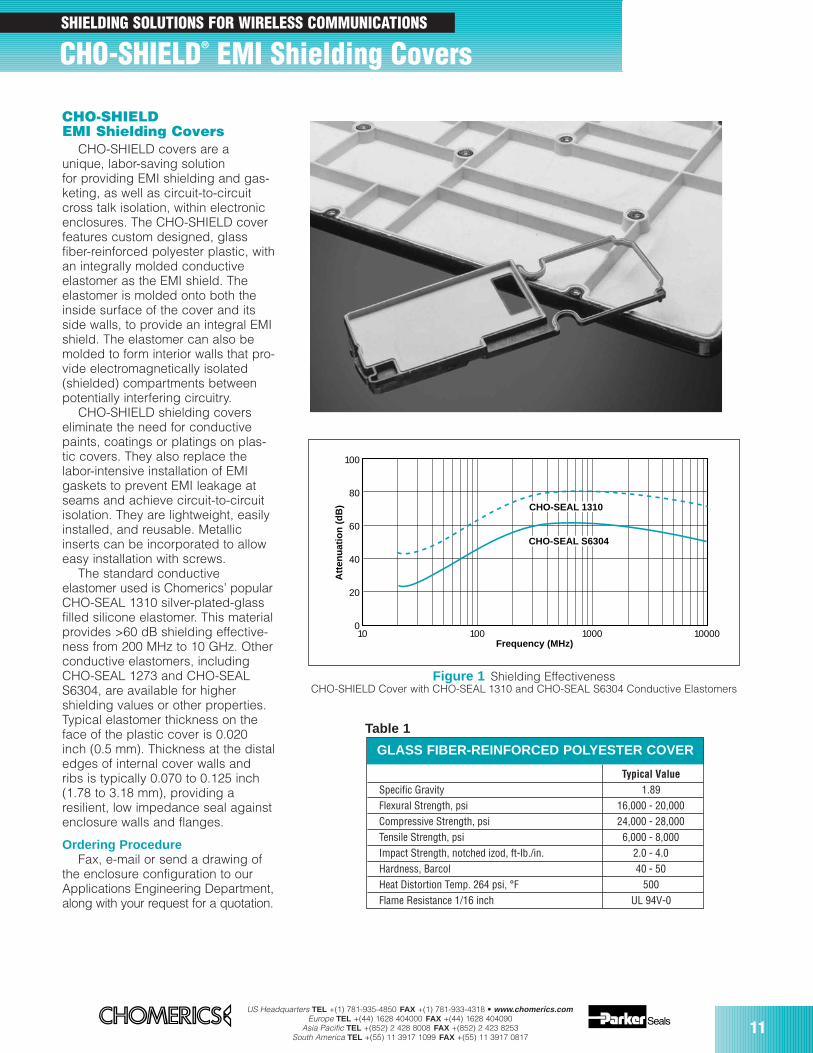
CHO-SHIELD covers are aunique, labor-saving solutionfor providing EMI shielding and gas-keting, as well as circuit-to-circuitcross talk isolation, within electronicenclosures. The CHO-SHIELD coverfeatures custom designed, glassfiber-reinforced polyester plastic, withan integrally molded conductiveelastomer as the EMI shield. Theelastomer is molded onto both theinside surface of the cover and itsside walls, to provide an integral EMIshield. The elastomer can also bemolded to form interior walls that pro-vide electromagnetically isolated(shielded) compartments betweenpotentially interfering circuitry.
CHO-SHIELD shielding coverseliminate the need for conductivepaints, coatings or platings on plas-tic covers. They also replace thelabor-intensive installation of EMIgaskets to prevent EMI leakage atseams and achieve circuit-to-circuitisolation. They are lightweight, easilyinstalled, and reusable. Metallicinserts can be incorporated to alloweasy installation with screws.
The standard conductiveelastomer used is Chomerics’ popularCHO-SEAL 1310 silver-plated-glassfilled silicone elastomer. This materialprovides >60 dB shielding effective-ness from 200 MHz to 10 GHz. Otherconductive elastomers, includingCHO-SEAL 1273 and CHO-SEALS6304, are available for highershielding values or other properties.Typical elastomer thickness on theface of the plastic cover is 0.020inch (0.5 mm). Thickness at the distaledges of internal cover walls andribs is typically 0.070 to 0.125 inch(1.78 to 3.18 mm), providing aresilient, low impedance seal againstenclosure walls and flanges.
Ordering ProcedureFax, e-mail or send a drawing of
the enclosure configuration to ourApplications Engineering Department,along with your request for a quotation.
100
80
60
40
20
010 100 1000 10000
Frequency (MHz)
Att
enu
atio
n (
dB
) CHO-SEAL 1310
CHO-SEAL S6304
Figure 1 Shielding EffectivenessCHO-SHIELD Cover with CHO-SEAL 1310 and CHO-SEAL S6304 Conductive Elastomers
GLASS FIBER-REINFORCED POLYESTER COVER
Table 1
CHO-SHIELD® EMI Shielding CoversSHIELDING SOLUTIONS FOR WIRELESS COMMUNICATIONS
Typical ValueSpecific Gravity 1.89Flexural Strength, psi 16,000 - 20,000Compressive Strength, psi 24,000 - 28,000Tensile Strength, psi 6,000 - 8,000Impact Strength, notched izod, ft-lb./in. 2.0 - 4.0Hardness, Barcol 40 - 50Heat Distortion Temp. 264 psi, °F 500Flame Resistance 1/16 inch UL 94V-0
12US Headquarters TEL +(1) 781-935-4850 FAX +(1) 781-933-4318 • www.chomerics.com
Europe TEL +(44) 1628 404000 FAX +(44) 1628 404090Asia Pacific TEL +(852) 2 428 8008 FAX +(852) 2 423 8253
South America TEL +(55) 11 3917 1099 FAX +(55) 11 3917 0817
CHO-VER SHIELD™ Covers
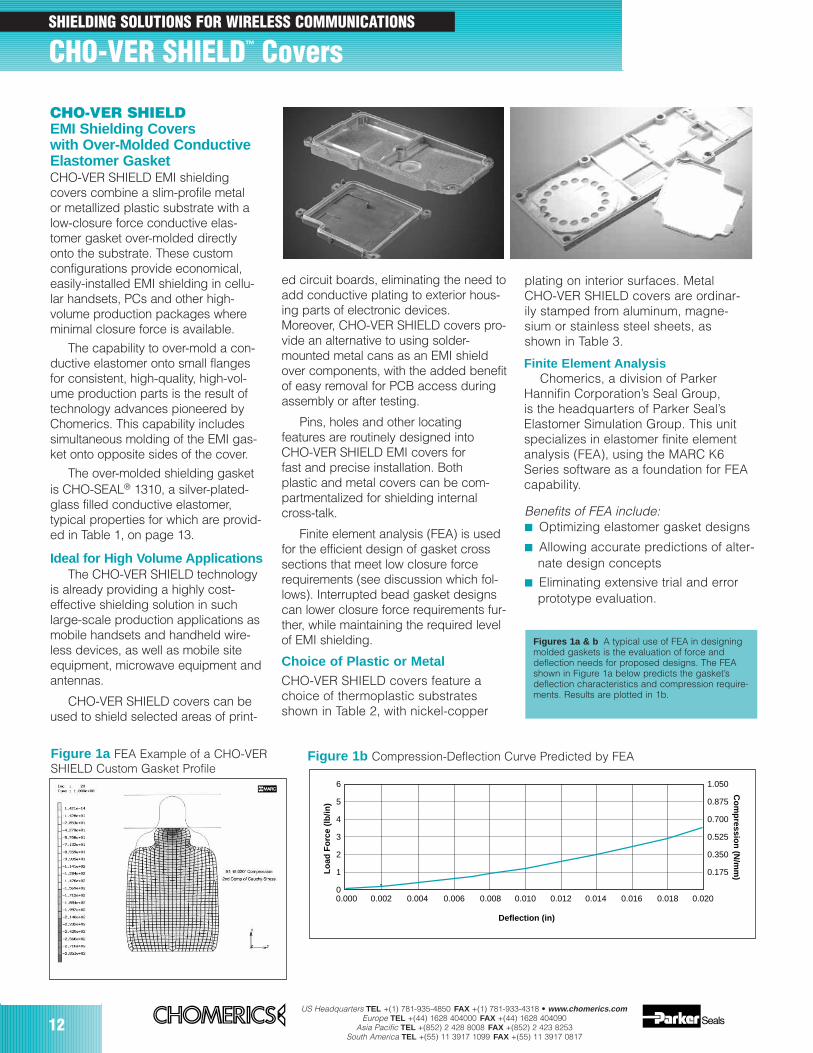
CHO-VER SHIELDEMI Shielding Covers with Over-Molded ConductiveElastomer GasketCHO-VER SHIELD EMI shielding covers combine a slim-profile metal or metallized plastic substrate with alow-closure force conductive elas-tomer gasket over-molded directlyonto the substrate. These custom configurations provide economical,easily-installed EMI shielding in cellu-lar handsets, PCs and other high-volume production packages whereminimal closure force is available.
The capability to over-mold a con-ductive elastomer onto small flangesfor consistent, high-quality, high-vol-ume production parts is the result oftechnology advances pioneered byChomerics. This capability includessimultaneous molding of the EMI gas-ket onto opposite sides of the cover.
The over-molded shielding gasketis CHO-SEAL® 1310, a silver-plated-glass filled conductive elastomer, typical properties for which are provid-ed in Table 1, on page 13.
Ideal for High Volume ApplicationsThe CHO-VER SHIELD technology
is already providing a highly cost-effective shielding solution in suchlarge-scale production applications asmobile handsets and handheld wire-less devices, as well as mobile siteequipment, microwave equipment andantennas.
CHO-VER SHIELD covers can beused to shield selected areas of print-
ed circuit boards, eliminating the need toadd conductive plating to exterior hous-ing parts of electronic devices.Moreover, CHO-VER SHIELD covers pro-vide an alternative to using solder-mounted metal cans as an EMI shieldover components, with the added benefitof easy removal for PCB access duringassembly or after testing.
Pins, holes and other locating features are routinely designed intoCHO-VER SHIELD EMI covers for fast and precise installation. Both plastic and metal covers can be com-partmentalized for shielding internal cross-talk.
Finite element analysis (FEA) is usedfor the efficient design of gasket crosssections that meet low closure forcerequirements (see discussion which fol-lows). Interrupted bead gasket designscan lower closure force requirements fur-ther, while maintaining the required levelof EMI shielding.
Choice of Plastic or MetalCHO-VER SHIELD covers feature achoice of thermoplastic substratesshown in Table 2, with nickel-copper
Figure 1a FEA Example of a CHO-VER SHIELD Custom Gasket Profile
Figures 1a & b A typical use of FEA in designingmolded gaskets is the evaluation of force anddeflection needs for proposed designs. The FEAshown in Figure 1a below predicts the gasket’sdeflection characteristics and compression require-ments. Results are plotted in 1b.
Finite Element AnalysisChomerics, a division of Parker
Hannifin Corporation’s Seal Group, is the headquarters of Parker Seal’sElastomer Simulation Group. This unitspecializes in elastomer finite elementanalysis (FEA), using the MARC K6Series software as a foundation for FEAcapability.
Benefits of FEA include: Optimizing elastomer gasket designs
Allowing accurate predictions of alter-nate design concepts
Eliminating extensive trial and errorprototype evaluation.
6
5
4
3
2
1
0
1.050
0.875
0.700
0.525
0.350
0.175
0.000 0.002 0.004 0.006 0.008 0.010 0.012 0.014 0.016 0.018 0.020
Compression-Deflection Curve Predicted by FEA
Deflection (in)
Lo
ad F
orc
e (l
b/in
)
Co
mp
ression
(N/m
m)
Figure 1b Compression-Deflection Curve Predicted by FEA
SHIELDING SOLUTIONS FOR WIRELESS COMMUNICATIONS
plating on interior surfaces. MetalCHO-VER SHIELD covers are ordinar-ily stamped from aluminum, magne-sium or stainless steel sheets, asshown in Table 3.

US Headquarters TEL +(1) 781-935-4850 FAX +(1) 781-933-4318 • www.chomerics.comEurope TEL +(44) 1628 404000 FAX +(44) 1628 404090
Asia Pacific TEL +(852) 2 428 8008 FAX +(852) 2 423 8253South America TEL +(55) 11 3917 1099 FAX +(55) 11 3917 0817
13
Table 1
*Copies of CHO-TM-TP08 (Shielding Effectiveness Test Method for EMI Gaskets) and CEPS-0002 are available from Chomerics
Table 2
TYPICAL PROPERTIES OF THERMOPLASTIC COVERS (without plating)
Property Test Procedure Vectra A130 LCP1 IXEF 1032 PAA2 ULTEM 1000 PEI3
Tensile Strength, yield, Type 1, 0.125 inch (3.2 mm), psi (MPa) ASTM D638 30,000 (207) 40,600 (280) 20,100 (139)Tensile Elongation, break, Type 1, 0.125 inch (3.2 mm), % ASTM D638 2.2 1.8 3.0Flexural Strength, break, 0.125 inch (3.2 mm), psi (MPa) ASTM D790 37,000 (254) 58,000 (400) 30,000 (207)Flexural Modulus, 0.125 inch (3.2 mm), psi (MPa) ASTM D790 2,100,000 (15,000) 3,050,000 (21,000) 900,000 (6,200)Compression Strength, psi (MPa) ASTM D695 20,000 (140) NA 28,700 (198)Compression Modulus, psi (MPa) ASTM D695 1,700,000 (12,000) NA 809,000 (5,575)Izod Impact, notched, 73°F (23°C), ft-lb/in (J/m) ASTM D256 2.8 (150) 2.25 (120) 1.6 (85)HDT, 66 psi (0.45 MPa), 0.250 in., (6.4 mm), unannealed, °F (°C) ASTM D648 489 (254) 446 (230) 410 (210)Specific Gravity ASTM D792 1.61 1.77 1.42Volume Resistivity, ohm-cm ASTM D257 10 x 1015 2.0 x 10¹⁵ 70 x 1015
UL 94V-0 Flame Class Rating, inch (mm) UL 94 0.018 (0.45) HB Rated 0.016 (0.40)Limiting Oxygen Index (LOI), % ASTM 2863 37 25 50
Contact Chomerics’ Applications Engineering to evaluate CHO-VER SHIELD Covers in your application.
1 Celanese AG2 Solvay SA3 General Electric Co. Note: ULTEM 1000 is used for low quantity prototyping only
Property Test Aluminum Die Thixo-Molded Stainless SteelProcedure Casting Magnesium
Alloy Number A380.0 AZ91D-F 316LTensile Strength, yield, psi (MPa) 0.2% offset 23,055 (159) 21,750 (150) 42,800 (295)Elongation, %, break in 50 mm 3.5 3 46Modulus of Elasticity, ksi (GPa) in tension 10,295 (71) 6,496 (44.8) 29,000 (200)
Fatigue Strength, psi (MPa) R.R. Moore Test, 20,010 (138) 14,065 (97) NA5E+8 cycles
Shear Modulus, ksi (GPa) — 3,843 (26.5) 2,465 (17) NAElectrical Resistivity, ohm-cm — 0.0000064 0.000017 0.000000074Density (g/cc) — 2.76 1.81 NA
NA = Not Applicable
TYPICAL PROPERTIES OF METAL SUBSTRATES
Table 3
CHO-VER SHIELD COVERS ELASTOMER SPECIFICATIONS
Property Test Procedure CHO-SEAL 1310
Elastomer Binder — SiliconeConductive Filler — Ag/GlassVolume Resistivity (ohm-cm), max CEPS-0002* 0.01Hardness (Shore A) ASTM 2240 70 ±10Specific Gravity ASTM D792 1.8 ±0.25Tensile Strength, psi, min. (MPa, min) ASTM D412 200 (1.38)Elongation, %, min. ASTM D412 100Compression Set, 70 hrs. @ 100°C. %, max. ASTM D395 Method B 35Shielding Effectiveness CHO-TM-TP08*
100 MHz (E-Field) 100500 MHz (E-Field) 1002 GHz (Plane Wave) 9010 GHz (Plane Wave) 80
Volume Resistivity After Heat Aging, ohm-cm, max. CEPS-0002* 0.01
Contact Chomerics regarding alternative metal substrates
14US Headquarters TEL +(1) 781-935-4850 FAX +(1) 781-933-4318 • www.chomerics.com
Europe TEL +(44) 1628 404000 FAX +(44) 1628 404090Asia Pacific TEL +(852) 2 428 8008 FAX +(852) 2 423 8253
South America TEL +(55) 11 3917 1099 FAX +(55) 11 3917 0817
EMI Shielding/Grounding Spacer Gaskets
Superior elongation and tensilestrength help to prevent tearing inuse due to mishandling. Typical prop-erties for CHO-SEAL 1310 and 1273material are shown on pages 33 and32 respectively.
High Shielding PerformanceCHO-SEAL 1310 material provides
more than 80 dB of shielding effectiv-ness from 100 MHz to 10 GHz, while CHO-SEAL 1273 material providesmore than 100 dB.
Low Volume ResistivityBoth materials have exceptionally
low volume resistivity, which makesthem well suited for grounding appli-cations in which a flexible electricalcontact is needed.
Low Compression GasketSpacer gaskets are typically
designed to function under lowdeflection forces. Chomerics usesdesign tools such as Finite ElementAnalysis (FEA) to accurately predictcompression-deflection behavior ofvarious cross section options. Referto page16.
LCP Plastic SpacerLiquid crystal polymer (LCP)
spacers, including those made withVectra A130 material, provide a
CHO-SEAL® 1310 or 1273Conductive Elastomers
With EMI spacer gaskets, shieldingand grounding are provided byChomerics’ CHO-SEAL 1310 and1273 conductive elastomers, specifi-cally formulated for custom shapemolded parts. They provide excellentshielding and isolation against electro-magnetic interference (EMI), or act as a low impedance ground pathbetween PCB traces and shieldingmedia. Physically tough, these elas-tomers minimize the risk of gasketdamage, in contrast to thin-walledextrusions or unsupported moldedgaskets.
Silicone-based CHO-SEAL 1310and 1273 materials offer excellentresistance to compression set over awide temperature range, resulting inyears of continuous service. CHO-SEAL 1310 material is filled with silver-plated-glass particles, while 1273 utilizes silver-plated-copper filler toprovide higher levels of EMI shieldingeffectiveness.
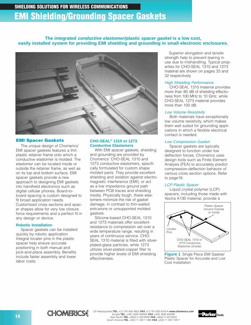
EMI Spacer GasketsThe unique design of Chomerics’
EMI spacer gaskets features a thinplastic retainer frame onto which aconductive elastomer is molded. Theelastomer can be located inside oroutside the retainer frame, as well ason its top and bottom surface. EMIspacer gaskets provide a newapproach to designing EMI gasketsinto handheld electronics such asdigital cellular phones. Board-to-board spacing is custom designed tofit broad application needs.Customized cross sections and spac-er shapes allow for very low closureforce requirements and a perfect fit inany design or device.
Robotic InstallationSpacer gaskets can be installed
quickly by robotic application.Integral locater pins in the plasticspacer help ensure accuratepositioning in both manual andpick-and-place assembly. Benefitsinclude faster assembly and lowerlabor costs.
The integrated conductive elastomer/plastic spacer gasket is a low cost,easily installed system for providing EMI shielding and grounding in small electronic enclosures.
Figure 1 Single Piece EMI Gasket/Plastic Spacer for Accurate and Low Cost Installation
LocatorPins
CHO-SEAL 1310 or1273 ConductiveElastomer (Inside)
Plastic SpacerAround Outside
or Inside
SHIELDING SOLUTIONS FOR WIRELESS COMMUNICATIONS
US Headquarters TEL +(1) 781-935-4850 FAX +(1) 781-933-4318 • www.chomerics.comEurope TEL +(44) 1628 404000 FAX +(44) 1628 404090
Asia Pacific TEL +(852) 2 428 8008 FAX +(852) 2 423 8253South America TEL +(55) 11 3917 1099 FAX +(55) 11 3917 0817
15
Applications for EMISpacer Gaskets
The spacer gasket concept isespecially suited to digital and dualboard telephone handsets or otherhandheld electronic devices. Itprovides a low impedance pathbetween peripheral ground traceson printed circuit boards andcomponents such as: the conductive coating on a
plastic housing another printed circuit board the keypad assembly
Typical applications for EMIspacer gaskets include: Digital cellular, handyphone and
personal communications services(PCS) handsets
PCMCIA cards Global Positioning Systems (GPS) Radio receivers Other handheld electronics, e.g.,
personal digital assistants (PDAs) Replacements for metal EMI
shielding “fences” on printedcircuit boards in wireless tele-communications devices
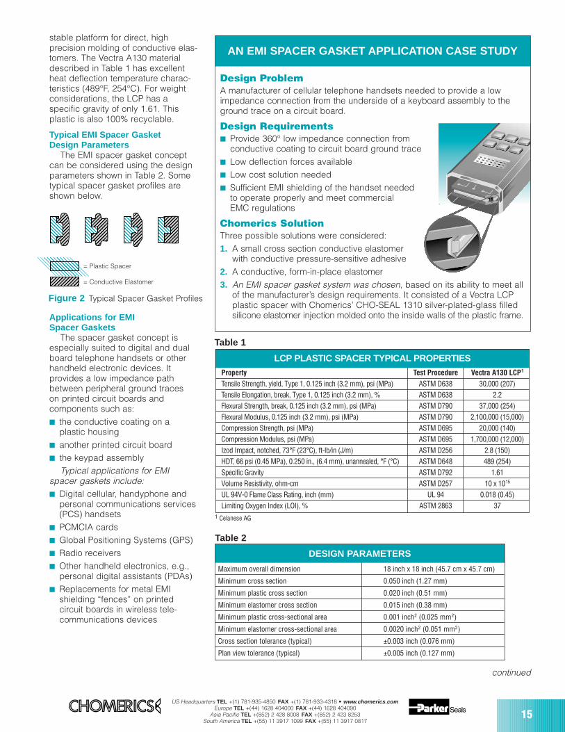
stable platform for direct, highprecision molding of conductive elas-tomers. The Vectra A130 materialdescribed in Table 1 has excellentheat deflection temperature charac-teristics (489°F, 254°C). For weightconsiderations, the LCP has aspecific gravity of only 1.61. Thisplastic is also 100% recyclable.
Typical EMI Spacer Gasket Design Parameters
The EMI spacer gasket conceptcan be considered using the designparameters shown in Table 2. Sometypical spacer gasket profiles areshown below.
Table 1
DESIGN PARAMETERS
Maximum overall dimension 18 inch x 18 inch (45.7 cm x 45.7 cm)
Minimum cross section 0.050 inch (1.27 mm)
Minimum plastic cross section 0.020 inch (0.51 mm)
Minimum elastomer cross section 0.015 inch (0.38 mm)
Minimum plastic cross-sectional area 0.001 inch2 (0.025 mm2)
Minimum elastomer cross-sectional area 0.0020 inch2 (0.051 mm2)
Cross section tolerance (typical) ±0.003 inch (0.076 mm)
Plan view tolerance (typical) ±0.005 inch (0.127 mm)
Table 2
Figure 2 Typical Spacer Gasket Profiles
= Plastic Spacer
= Conductive Elastomer
AN EMI SPACER GASKET APPLICATION CASE STUDY
Design ProblemA manufacturer of cellular telephone handsets needed to provide a lowimpedance connection from the underside of a keyboard assembly to theground trace on a circuit board.
Design Requirements Provide 360° low impedance connection from
conductive coating to circuit board ground trace Low deflection forces available Low cost solution needed Sufficient EMI shielding of the handset needed
to operate properly and meet commercialEMC regulations
Chomerics SolutionThree possible solutions were considered:1. A small cross section conductive elastomer
with conductive pressure-sensitive adhesive2. A conductive, form-in-place elastomer3. An EMI spacer gasket system was chosen, based on its ability to meet all
of the manufacturer’s design requirements. It consisted of a Vectra LCPplastic spacer with Chomerics’ CHO-SEAL 1310 silver-plated-glass filledsilicone elastomer injection molded onto the inside walls of the plastic frame.
continued
LCP PLASTIC SPACER TYPICAL PROPERTIES
Property Test Procedure Vectra A130 LCP1
Tensile Strength, yield, Type 1, 0.125 inch (3.2 mm), psi (MPa) ASTM D638 30,000 (207)Tensile Elongation, break, Type 1, 0.125 inch (3.2 mm), % ASTM D638 2.2Flexural Strength, break, 0.125 inch (3.2 mm), psi (MPa) ASTM D790 37,000 (254)Flexural Modulus, 0.125 inch (3.2 mm), psi (MPa) ASTM D790 2,100,000 (15,000)Compression Strength, psi (MPa) ASTM D695 20,000 (140)Compression Modulus, psi (MPa) ASTM D695 1,700,000 (12,000)Izod Impact, notched, 73°F (23°C), ft-lb/in (J/m) ASTM D256 2.8 (150)HDT, 66 psi (0.45 MPa), 0.250 in., (6.4 mm), unannealed, °F (°C) ASTM D648 489 (254)Specific Gravity ASTM D792 1.61Volume Resistivity, ohm-cm ASTM D257 10 x 1015
UL 94V-0 Flame Class Rating, inch (mm) UL 94 0.018 (0.45)Limiting Oxygen Index (LOI), % ASTM 2863 37
1 Celanese AG
16US Headquarters TEL +(1) 781-935-4850 FAX +(1) 781-933-4318 • www.chomerics.com
Europe TEL +(44) 1628 404000 FAX +(44) 1628 404090Asia Pacific TEL +(852) 2 428 8008 FAX +(852) 2 423 8253
South America TEL +(55) 11 3917 1099 FAX +(55) 11 3917 0817
EMI Shielding/Grounding Spacer Gaskets continued
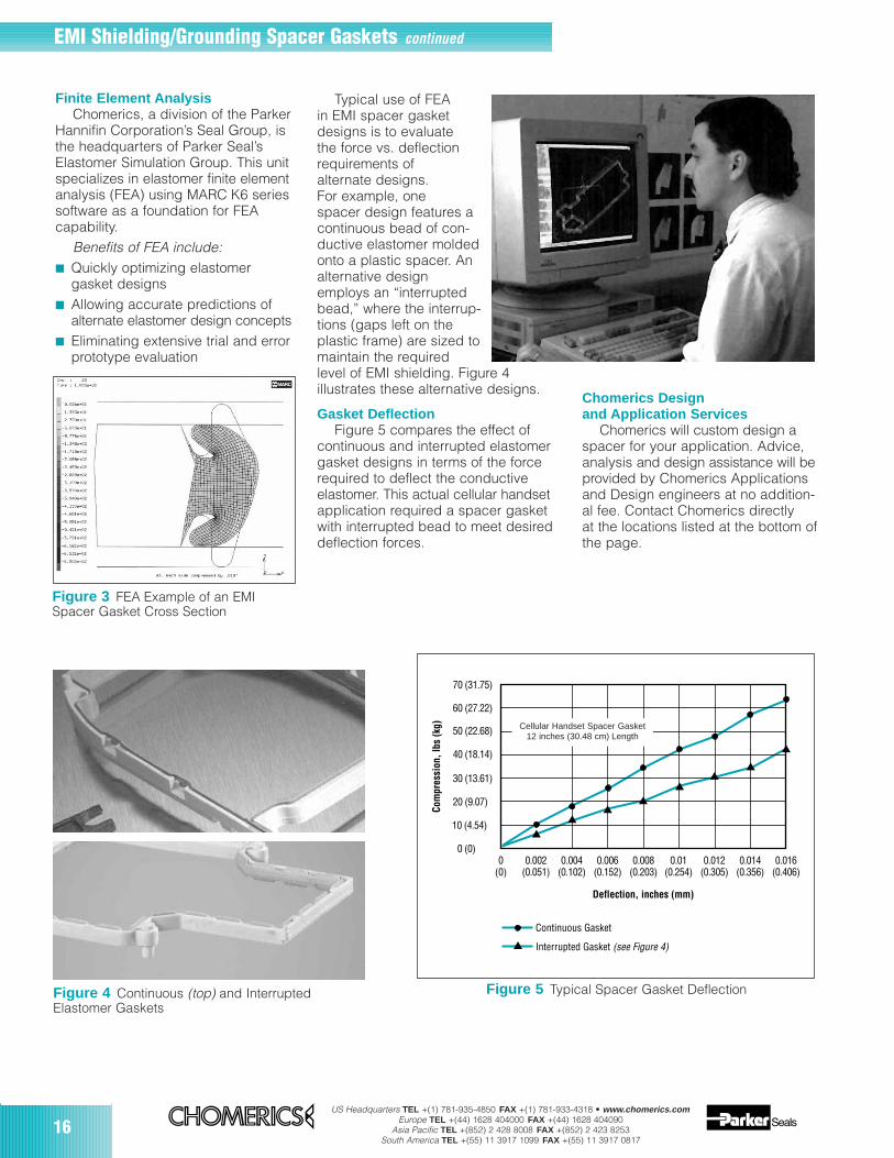
Finite Element AnalysisChomerics, a division of the Parker
Hannifin Corporation’s Seal Group, isthe headquarters of Parker Seal’sElastomer Simulation Group. This unitspecializes in elastomer finite elementanalysis (FEA) using MARC K6 seriessoftware as a foundation for FEAcapability.
Benefits of FEA include: Quickly optimizing elastomer
gasket designs Allowing accurate predictions of
alternate elastomer design concepts Eliminating extensive trial and error
prototype evaluation
Typical use of FEAin EMI spacer gasketdesigns is to evaluate the force vs. deflectionrequirements ofalternate designs.For example, onespacer design features acontinuous bead of con-ductive elastomer moldedonto a plastic spacer. Analternative designemploys an “interruptedbead,” where the interrup-tions (gaps left on theplastic frame) are sized tomaintain the required level of EMI shielding. Figure 4illustrates these alternative designs.
Gasket DeflectionFigure 5 compares the effect of
continuous and interrupted elastomergasket designs in terms of the forcerequired to deflect the conductiveelastomer. This actual cellular handsetapplication required a spacer gasketwith interrupted bead to meet desireddeflection forces.
Chomerics Designand Application Services
Chomerics will custom design aspacer for your application. Advice,analysis and design assistance will beprovided by Chomerics Applicationsand Design engineers at no addition-al fee. Contact Chomerics directlyat the locations listed at the bottom ofthe page.
Figure 3 FEA Example of an EMISpacer Gasket Cross Section
Figure 4 Continuous (top) and Interrupted Elastomer Gaskets
Figure 5 Typical Spacer Gasket Deflection
70 (31.75)
60 (27.22)
50 (22.68)
40 (18.14)
30 (13.61)
20 (9.07)
10 (4.54)
0 (0)0
(0)0.002
(0.051)0.004
(0.102)0.006
(0.152)0.008
(0.203)0.01
(0.254)0.012
(0.305)0.014
(0.356)0.016
(0.406)
Com
pres
sion
, lbs
(kg)
Continuous Gasket
Interrupted Gasket (see Figure 4)
Deflection, inches (mm)
Cellular Handset Spacer Gasket12 inches (30.48 cm) Length
US Headquarters TEL +(1) 781-935-4850 FAX +(1) 781-933-4318 • www.chomerics.comEurope TEL +(44) 1628 404000 FAX +(44) 1628 404090
Asia Pacific TEL +(852) 2 428 8008 FAX +(852) 2 423 8253South America TEL +(55) 11 3917 1099 FAX +(55) 11 3917 0817
17
Conductive Coating Spray OperationsSHIELDING SOLUTIONS FOR WIRELESS COMMUNICATIONS
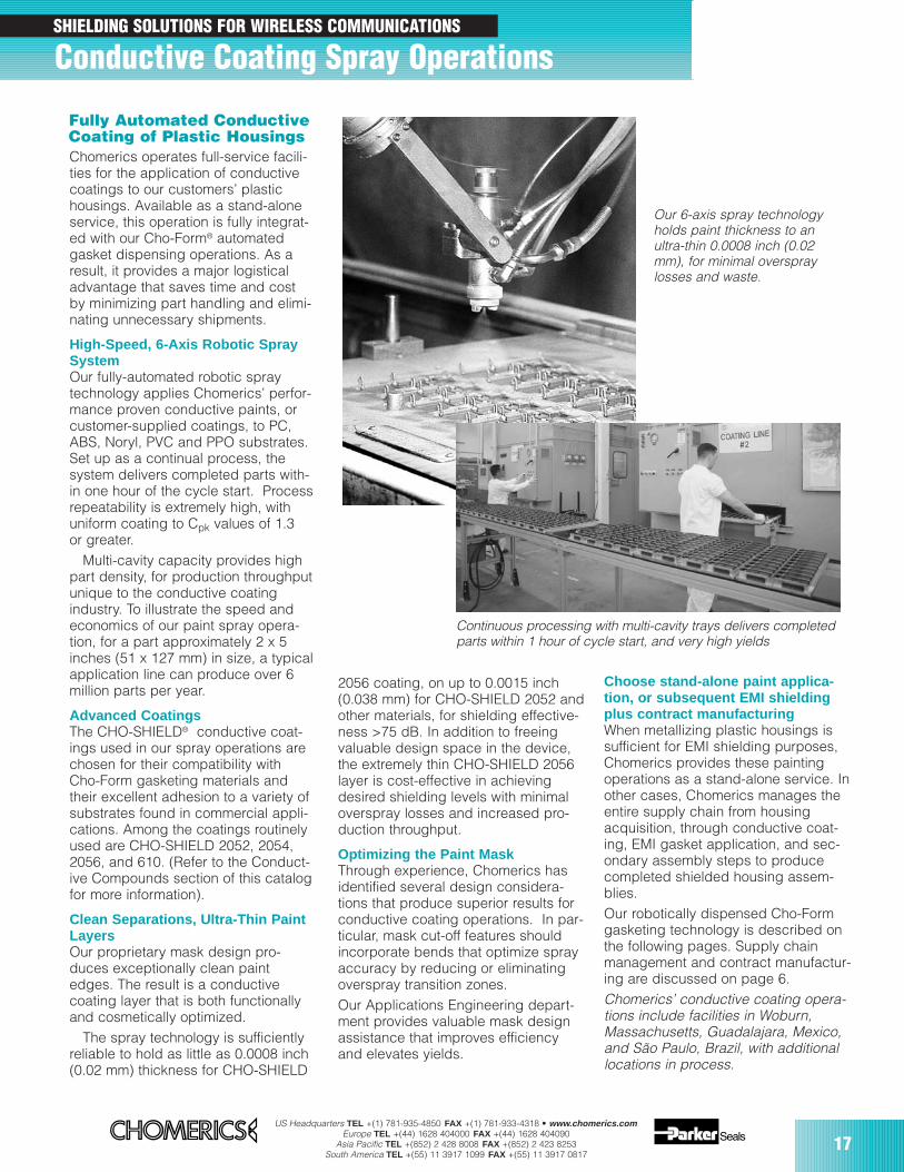
Fully Automated ConductiveCoating of Plastic HousingsChomerics operates full-service facili-ties for the application of conductivecoatings to our customers’ plastichousings. Available as a stand-aloneservice, this operation is fully integrat-ed with our Cho-Form® automatedgasket dispensing operations. As aresult, it provides a major logisticaladvantage that saves time and costby minimizing part handling and elimi-nating unnecessary shipments.
High-Speed, 6-Axis Robotic SpraySystemOur fully-automated robotic spraytechnology applies Chomerics’ perfor-mance proven conductive paints, orcustomer-supplied coatings, to PC,ABS, Noryl, PVC and PPO substrates.Set up as a continual process, thesystem delivers completed parts with-in one hour of the cycle start. Processrepeatability is extremely high, withuniform coating to Cpk values of 1.3 or greater.
Multi-cavity capacity provides highpart density, for production throughputunique to the conductive coatingindustry. To illustrate the speed andeconomics of our paint spray opera-tion, for a part approximately 2 x 5inches (51 x 127 mm) in size, a typicalapplication line can produce over 6million parts per year.
Advanced CoatingsThe CHO-SHIELD® conductive coat-ings used in our spray operations arechosen for their compatibility withCho-Form gasketing materials andtheir excellent adhesion to a variety ofsubstrates found in commercial appli-cations. Among the coatings routinelyused are CHO-SHIELD 2052, 2054,2056, and 610. (Refer to the Conduct-ive Compounds section of this catalogfor more information).
Clean Separations, Ultra-Thin PaintLayersOur proprietary mask design pro-duces exceptionally clean paintedges. The result is a conductivecoating layer that is both functionallyand cosmetically optimized.
The spray technology is sufficientlyreliable to hold as little as 0.0008 inch(0.02 mm) thickness for CHO-SHIELD
2056 coating, on up to 0.0015 inch(0.038 mm) for CHO-SHIELD 2052 andother materials, for shielding effective-ness >75 dB. In addition to freeingvaluable design space in the device,the extremely thin CHO-SHIELD 2056layer is cost-effective in achievingdesired shielding levels with minimaloverspray losses and increased pro-duction throughput.
Optimizing the Paint MaskThrough experience, Chomerics hasidentified several design considera-tions that produce superior results forconductive coating operations. In par-ticular, mask cut-off features shouldincorporate bends that optimize sprayaccuracy by reducing or eliminatingoverspray transition zones.Our Applications Engineering depart-ment provides valuable mask designassistance that improves efficiencyand elevates yields.
Choose stand-alone paint applica-tion, or subsequent EMI shieldingplus contract manufacturingWhen metallizing plastic housings issufficient for EMI shielding purposes,Chomerics provides these paintingoperations as a stand-alone service. Inother cases, Chomerics manages theentire supply chain from housingacquisition, through conductive coat-ing, EMI gasket application, and sec-ondary assembly steps to producecompleted shielded housing assem-blies. Our robotically dispensed Cho-Formgasketing technology is described onthe following pages. Supply chainmanagement and contract manufactur-ing are discussed on page 6.Chomerics’ conductive coating opera-tions include facilities in Woburn,Massachusetts, Guadalajara, Mexico,and São Paulo, Brazil, with additionallocations in process.
Continuous processing with multi-cavity trays delivers completedparts within 1 hour of cycle start, and very high yields
Our 6-axis spray technologyholds paint thickness to anultra-thin 0.0008 inch (0.02mm), for minimal overspraylosses and waste.

18US Headquarters TEL +(1) 781-935-4850 FAX +(1) 781-933-4318 • www.chomerics.com
Europe TEL +(44) 1628 404000 FAX +(44) 1628 404090Asia Pacific TEL +(852) 2 428 8008 FAX +(852) 2 423 8253
South America TEL +(55) 11 3917 1099 FAX +(55) 11 3917 0817
Excellent Shielding Effectiveness,Even in Small Cross SectionsShielding effectiveness of Cho-Formgaskets exceeds 85 dB between 200MHz and 10 GHz. Shielding perfor-mance increases with cross sectionaldimensions. Results shown for vari-ous Cho-Form materials wereobtained using very small gaskets,0.034 inch high by 0.040 inch wide(0.86 mm high by 1.0 mm wide)
Denser Packagingis Possible Cho-Form gaskets can be applied towalls or flanges as narrow as 0.020inch (0.50 mm), and don’t requiremechanical retention. Comparedwith groove and friction-fit designs,the positional accuracy and self-adhesive properties of Cho-Form
Chomerics’ Cho-Form Automated EMI GasketingSystem was developed to meet the growing demand forhigh-speed, high volume application of conductive elastomerseals to metal or plastic housings. It is ideal for cellular hand-sets, PC cards, compartmentalized enclosures and othertightly packaged commercial electronic devices.
Cho-Form technology allows dispensing of precisely posi-tioned, conformable gaskets in very small cross sections thatfree valuable package space. The durable, highly conductiveseals have low compression set, ensuring years of effectiveEMI shielding and mechanical performance.
With gasket dispensing primari-ly software driven, Cho-Formtechnology permits rapid proto-typing, changes in design, andproduction scale-up at nominalcost. Its inherent flexibilityaccommodates batch runs orcontinuous production, from tento ten million parts.
Wide acceptance of the Cho-Form automated gasket dispens-ing system can be attributed to a successful blend of manufac-turing and materials expertise.Among its important design andperformance benefits are:
up to 60% space saved —flanges as narrow as 0.020 inch(0.50 mm) can be gasketed more than 75 dB shieldingeffectiveness from 200 MHz to10 GHz with very small gasketbeads accuracy for gasket locationwithin 0.001 inch (0.025 mm) more than 12 Newtons/cm2
shear adhesion to commonhousing substrates and coatings highly compressible gaskets,ideal with limited deflection force speed — gasketed parts typi-cally prototyped and shippedwithin several days
Outstanding Production Efficiencies Cho-Form technology dispenses EMIgasketing at ever-increasing rates inline with our commitment to reducecosts. Our continuous improvementprogram has enabled us to increasethe dispense rate eight-fold in threeyears, and we pursue additionalimprovements. The commitment toreducing costs extends to allaspects of the dispensing operation,with the goal of offering superiorquality at constantly lower prices.
Cho-Form® Robotically DispensedForm-in-Place EMI Gasketing
SHIELDING SOLUTIONS FOR WIRELESS COMMUNICATIONS
US Headquarters TEL +(1) 781-935-4850 FAX +(1) 781-933-4318 • www.chomerics.comEurope TEL +(44) 1628 404000 FAX +(44) 1628 404090
Asia Pacific TEL +(852) 2 428 8008 FAX +(852) 2 423 8253South America TEL +(55) 11 3917 1099 FAX +(55) 11 3917 0817
19
continued
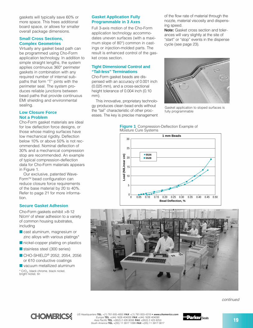
Figure 1 Compression-Deflection Example ofMoisture Cure Systems
Gasket Application FullyProgrammable in 3 Axes
Full 3-axis motion of the Cho-Formapplication technology accommo-dates uneven surfaces (with a maxi-mum slope of 80°) common in cast-ings or injection-molded parts. Theresult is enhanced control of the gas-ket cross section.
Tight Dimensional Control and“Tail-less” TerminationsCho-Form gasket beads are dis-pensed with an accuracy of 0.001 inch(0.025 mm), and a cross-sectionalheight tolerance of 0.004 inch (0.10mm).
This innovative, proprietary technolo-gy produces clean bead ends withoutthe “tail” characteristic of other proc-esses. The key is precise management
of the flow rate of material through thenozzle, material viscosity and dispens-ing speed. Note: Gasket cross section and toler-ances will vary slightly at the site of“start” or “stop” events in the dispensecycle (see page 23).
gaskets will typically save 60% ormore space. This frees additionalboard space, or allows for smalleroverall package dimensions.
Small Cross Sections, Complex GeometriesVirtually any gasket bead path canbe programmed using Cho-Formapplication technology. In addition tosimple straight lengths, the systemapplies continuous 360° perimetergaskets in combination with anyrequired number of internal sub-paths that form “T” joints with theperimeter seal. The system pro-duces reliable junctions betweenbead paths that provide continuousEMI shielding and environmentalsealing.
Low Closure Force Not a ProblemCho-Form gasket materials are idealfor low deflection force designs, orthose whose mating surfaces havelow mechanical rigidity. Deflectionbelow 10% or above 50% is not rec-ommended. Nominal deflection of30% and a mechanical compressionstop are recommended. An exampleof typical compression-deflectiondata for Cho-Form materials appearsin Figure 1.
Our exclusive, patented Wave-FormTM bead configuration canreduce closure force requirements of the base material by 20 to 40%.Refer to page 21 for more informa-tion.
Secure Gasket AdhesionCho-Form gaskets exhibit >8-12N/cm2 of shear adhesion to a varietyof common housing substrates,including
cast aluminum, magnesium or zinc alloys with various platings*
nickel-copper plating on plastics
stainless steel (300 series)
CHO-SHIELD® 2052, 2054, 2056 or 610 conductive coatings
vacuum metallized aluminum* CrO4, black chrome, black nickel, bright nickel, tin
Gasket application to sloped surfaces isfully programmable
5
00 0.05 0.10 0.20 0.25 0.30 0.35 0.40 0.45 0.500.15
10
15
20
25
30
Bead Deflection, %
1 mm Beads
Lo
ad (
N/L
inea
r cm
) 55265528
20US Headquarters TEL +(1) 781-935-4850 FAX +(1) 781-933-4318 • www.chomerics.com
Europe TEL +(44) 1628 404000 FAX +(44) 1628 404090Asia Pacific TEL +(852) 2 428 8008 FAX +(852) 2 423 8253
South America TEL +(55) 11 3917 1099 FAX +(55) 11 3917 0817
High Levels of Quality ControlChomerics performs automateddimensional verification of gasketbead placement and height for statis-tical process control, using fully pro-grammable optical coordinate mea-suring technology and vision systems.Electrical resistance of cured gasketmaterial is tested with a multimetercapable of measuring to 0.001 ohm.Typical Cp and Cpk values are approxi-mately 1.5.
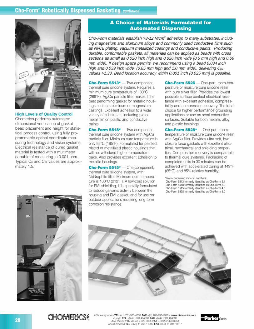
A Choice of Materials Formulated for Automated Dispensing
Cho-Form 5513* — Two-component,thermal cure silicone system. Requires aminimum cure temperature of 130°C(266°F). Ag/Cu particle filler makes it thebest performing gasket for metallic hous-ings such as aluminum or magnesiumcastings. Excellent adhesion to a widevariety of substrates, including platedmetal film on plastic and conductivepaints. Cho-Form 5518* — Two-component,thermal cure silicone system with Ag/Cuparticle filler. Minimum cure temperature isonly 85°C (185°F). Formulated for painted,plated or metallized plastic housings thatwill not withstand higher temperaturebake. Also provides excellent adhesion tometallic housings. Cho-Form 5515* — One-component,thermal cure silicone system, withNi/Graphite filler. Minimum cure tempera-ture is 100°C (212°F). A low-cost solutionfor EMI shielding, it is specially formulatedto reduce galvanic activity between thehousing and EMI gasket, and for use onoutdoor applications requiring long-termcorrosion resistance.
Cho-Form 5526 — One-part, room-tem-perature or moisture cure silicone resinwith pure silver filler. Provides the lowestpossible surface contact electrical resis-tance with excellent adhesion, compress-ibility and compression recovery. The idealchoice for higher performance groundingapplications or use on semi-conductivesurfaces. Suitable for both metallic alloyand plastic housings.Cho-Form 5528* — One-part, room-temperature or moisture cure silicone resinwith Ag/Cu filler. Provides ultra-soft, lowclosure force gaskets with excellent elec-trical, mechanical and shielding proper-ties. Compression recovery is comparableto thermal cure systems. Packaging ofcompleted units in 30 minutes can beachieved with accelerated curing at 149°F(65°C) and 85% relative humidity.
Cho-Form® Robotically Dispensed Gasketing continued
Cho-Form materials establish >8-12 N/cm2 adhesion to many substrates, includ-ing magnesium and aluminum alloys and commonly used conductive films suchas Ni/Cu plating, vacuum metallized coatings and conductive paints. Producingdurable, conformable gaskets, all materials can be applied as beads with crosssections as small as 0.020 inch high and 0.026 inch wide (0.5 mm high and 0.66mm wide). If design space permits, we recommend using a bead 0.034 inchhigh and 0.039 inch wide (0.85 mm high and 1.0 mm wide), delivering Cpk
values >1.33. Bead location accuracy within 0.001 inch (0.025 mm) is possible.
*Note concerning material numbers:Cho-Form 5513 formerly identified as Cho-Form 2.1Cho-Form 5518 formerly identified as Cho-Form 3.0 Cho-Form 5515 formerly identified as Cho-Form 4.0Cho-Form 5528 formerly identified as Cho-Form 5.0
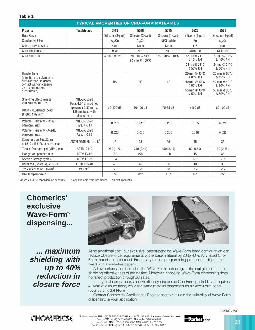
TYPICAL PROPERTIES OF CHO-FORM MATERIALS
Property Test Method 5513 5518 5515 5526 5528
Base Resin Silicone (2-part) Silicone (2-part) Silicone (1-part) Silicone (1-part) Silicone (1-part)
Conductive Filler Ag/Cu Ag/Cu Ni/Graphite Ag Ag/Cu
Solvent Level, Wet,% None None None 5-8 None
Cure Mechanism Heat Heat Heat Moisture Moisture
Cure Schedule 30 min @ 140°C 30 min @ 85°C 30 min @ 140°C 72 hrs @ 21°C 72 hrs @ 21°C& 10% RH & 10% RH20 min @ 100°C
24 hrs @ 21°C 24 hrs @ 21°C& 50% RH & 50% RH
Handle Time 20 min @ 65°C 20 min @ 65°C& 85% RH & 85% RH
NA NA NA 40 min @ 40°C 40 min @ 40°C& 50% RH & 50% RH
55 min @ 30°C 55 min @ 30°C& 50% RH & 50% RH
Shielding Effectiveness MIL-G-83528200 MHz to 10 GHz, Para. 4.6.12, modified
specimen 0.85 mm x 80-100 dB 80-100 dB 75-85 dB >100 dB 80-100 dB0.034 x 0.040 inch bead 1.0 mm bead with(0.86 x 1.02 mm) plastic bolts
Volume Resistivity (Initial), MIL-G-835280.010 0.010 0.200 0.005 0.020
ohm-cm, max. Para. 4.6.11
Volume Resistivity (Aged), MIL-G-835280.020 0.050 0.300 0.010 0.030
ohm-cm, max. Para. 4.6.15
Compression Set, 22 hrs.at 85°C (185°F), percent, max.
ASTM D395 Method B2 25 35 25 35 35
Tensile Strength, psi (MPa), min. ASTM D412 250 (1.72) 350 (2.41) 450 (3.10) 80 (0.55) 80 (0.55)
Elongation, percent, min. ASTM D412 250 225 100 45 45
Specific Gravity, typical ASTM D792 3.4 3.3 1.8 3.3 2.7
Hardness (Shore A), +15, –10 ASTM D2240 45 45 60 40 35
Typical Adhesion1, N/cm2 WI 0382 >8 >8 >8 >12 >12
Use Temperature, °C 85° 85° 100° 85° 85°
US Headquarters TEL +(1) 781-935-4850 FAX +(1) 781-933-4318 • www.chomerics.comEurope TEL +(44) 1628 404000 FAX +(44) 1628 404090
Asia Pacific TEL +(852) 2 428 8008 FAX +(852) 2 423 8253South America TEL +(55) 11 3917 1099 FAX +(55) 11 3917 0817
21
continued
1Adhesion value dependant on substrate 2Copy available from Chomerics NA Not Applicable
Table 1
(min. time to obtain curesufficient for incidentalcontact without causingpermanent gasketdeformation)
Chomerics’exclusive Wave-Form TM
dispensing...
... maximumshielding with
up to 40% reduction in
closure force
At no additional cost, our exclusive, patent-pending Wave-Form bead configuration canreduce closure force requirements of the base material by 20 to 40%. Any listed Cho-Form material can be used. Proprietary motion programming produces a dispensedbead with a wave-like pattern.
A key performance benefit of the Wave-Form technology is its negligible impact onshielding effectiveness of the gasket. Moreover, choosing Wave-Form dispensing doesnot affect production throughput rates.
In a typical comparison, a conventionally dispensed Cho-Form gasket bead requires4 N/cm of closure force, while the same material dispensed as a Wave-Form beadrequires only 2.6 N/cm.
Contact Chomerics’ Applications Engineering to evaluate the suitability of Wave-Formdispensing in your application.

22US Headquarters TEL +(1) 781-935-4850 FAX +(1) 781-933-4318 • www.chomerics.com
Europe TEL +(44) 1628 404000 FAX +(44) 1628 404090Asia Pacific TEL +(852) 2 428 8008 FAX +(852) 2 423 8253
South America TEL +(55) 11 3917 1099 FAX +(55) 11 3917 0817
Important Considerations for OptimizingQuality & Production EfficiencyA shielded housing is an assem-bly whose quality and perfor-mance are functions of all theparts and processes used to pro-duce it.
Whenever possible, Chomericsinterfaces on behalf of OEM cus-tomers with suppliers of die-castmetal and injection-molded plas-tic housings in advance of tooldesign and production. Detailedguidance is provided on partand tool design, part repro-ducibility, locating features, tol-erances and surface conditions— issues that are key to thequality and economics of roboticgasket dispensing.
As discussed on page 6,Chomerics can act as lead ven-dor, managing the entire hous-ing supply chain to ensure thebest results for OEM customers.
The following section providesanswers to commonly askedquestions, and highlights criticaldesign issues that affect produc-tion efficiency and cost.
Housing MaterialConsiderationsPlastic Substrate SelectionIf the housing is an injection-moldedthermoplastic, the gasket cure tem-perature is an important parameter.Different thermoplastics soften orstress-relieve at different temperatures.
Polycarbonate/ABS blends offer significant process advantages forCho-Form gasket application. Whilesomewhat more expensive than otherplastics, virtually all PC/ABS blendswill withstand 85°C (185°F), and there-fore allow efficient gasket “quick cure”in-line. In contrast, plastics thatrequire room temperature gasket cur-ing necessitate batch processing,with attendant cost and logistic (time)disadvantages.
For maximum production through-put, Chomerics generally recom-mends that plastic housings be ableto withstand curing at 85°C for up to40 minutes without deforming.
Surface PreparationMetal or plastic surfaces to be gasketed with Cho-Form materialsshould exhibit electrical resistance of<0.01 ohm. They should be cleanand free of dirt, oils and organic solvents.Metallic housings must be treated toremove release agents and machin-ing oils. Aluminum parts should bechromate conversion coated (alodineor irridite) per MIL-C-5541 Class 3.Magnesium parts should be protectedwith Dow 20 modified chrome pickleor equivalent.Plastic housings require metallizing,which may be accomplished by plat-ing, aluminum vacuum deposition orconductive paint.For plating, nickel-copper is preferred.It adheres well, provides 80+ dB ofshielding effectiveness, and remainselectrically stable over time.If vacuum deposition is chosen, anitrogen purge is mandatory toensure good adhesion.
Differences in commercially avail-able conductive paints necessitatestesting them with the selected Cho-Form gasketing material. Chomerics’CHO-SHIELD® 2052, 2054, 2056 and610 conductive coatings have beenformulated to adhere well and be gal-vanically compatible with Cho-Formmaterials. The superior performanceand batch-to-batch uniformity of thesesilver-copper-filled paints have beenextensively demonstrated in theseapplications. Their high abrasionresistance provides protection duringproduct assembly and use.
Chomerics applies CHO-SHIELDcoatings robotically in-line, as anintegrated part of the automatedCho-Form application process. Thiscapability provides significant logisti-cal, time and cost benefits.
Protective PackagingTo avoid cosmetic injuries such assurface scratches, parts should beshipped in compartmentalized plas-tic or corrugated paper trays. Ifrequested, Chomerics will arrangefor specialized packaging to bedelivered to the housing manufac-turer.
Optimizing the design of Cho-Form Shielded Housing Assemblies
Cho-Form® Robotically Dispensed Gasketing continued
US Headquarters TEL +(1) 781-935-4850 FAX +(1) 781-933-4318 • www.chomerics.comEurope TEL +(44) 1628 404000 FAX +(44) 1628 404090
Asia Pacific TEL +(852) 2 428 8008 FAX +(852) 2 423 8253South America TEL +(55) 11 3917 1099 FAX +(55) 11 3917 0817
23
continued
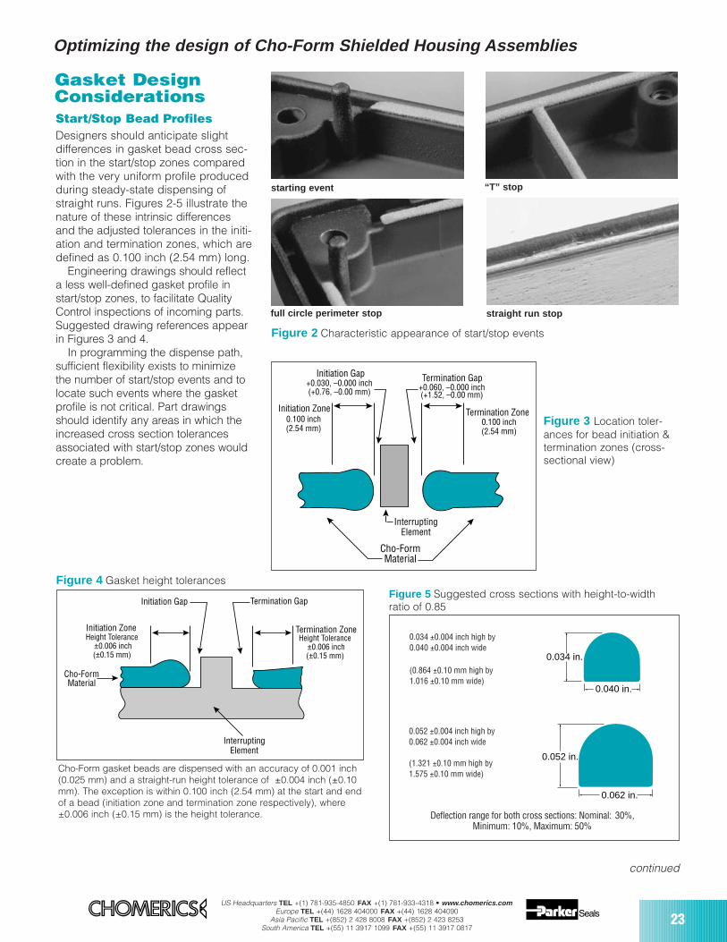
starting event
straight run stopfull circle perimeter stop
“T” stop
Figure 2 Characteristic appearance of start/stop events
Cho-Form Material
Interrupting Element
Initiation Gap Termination Gap
Termination ZoneInitiation Zone0.100 inch(2.54 mm)
0.100 inch(2.54 mm)
+0.030, –0.000 inch(+0.76, –0.00 mm) (+1.52, –0.00 mm)
+0.060, –0.000 inch
Gasket DesignConsiderationsStart/Stop Bead ProfilesDesigners should anticipate slight differences in gasket bead cross sec-tion in the start/stop zones comparedwith the very uniform profile producedduring steady-state dispensing ofstraight runs. Figures 2-5 illustrate thenature of these intrinsic differencesand the adjusted tolerances in the initi-ation and termination zones, which aredefined as 0.100 inch (2.54 mm) long.
Engineering drawings should reflecta less well-defined gasket profile instart/stop zones, to facilitate QualityControl inspections of incoming parts.Suggested drawing references appearin Figures 3 and 4.
In programming the dispense path,sufficient flexibility exists to minimizethe number of start/stop events and tolocate such events where the gasketprofile is not critical. Part drawingsshould identify any areas in which theincreased cross section tolerancesassociated with start/stop zones wouldcreate a problem.
Figure 3 Location toler-ances for bead initiation &termination zones (cross-sectional view)
Cho-Form gasket beads are dispensed with an accuracy of 0.001 inch(0.025 mm) and a straight-run height tolerance of ±0.004 inch (±0.10mm). The exception is within 0.100 inch (2.54 mm) at the start and endof a bead (initiation zone and termination zone respectively), where±0.006 inch (±0.15 mm) is the height tolerance.
Cho-Form Material
Interrupting Element
Termination ZoneHeight Tolerance
±0.006 inch(±0.15 mm)
Initiation ZoneHeight Tolerance
±0.006 inch(±0.15 mm)
Initiation Gap Termination Gap
Figure 4 Gasket height tolerancesFigure 5 Suggested cross sections with height-to-width ratio of 0.85
Deflection range for both cross sections: Nominal: 30%, Minimum: 10%, Maximum: 50%
0.052 ±0.004 inch high by 0.062 ±0.004 inch wide
(1.321 ±0.10 mm high by1.575 ±0.10 mm wide)
0.034 ±0.004 inch high by 0.040 ±0.004 inch wide
(0.864 ±0.10 mm high by 1.016 ±0.10 mm wide)
0.034 in.
0.040 in.
0.052 in.
0.062 in.
Optimizing the design of Cho-Form Shielded Housing Assemblies

24US Headquarters TEL +(1) 781-935-4850 FAX +(1) 781-933-4318 • www.chomerics.com
Europe TEL +(44) 1628 404000 FAX +(44) 1628 404090Asia Pacific TEL +(852) 2 428 8008 FAX +(852) 2 423 8253
South America TEL +(55) 11 3917 1099 FAX +(55) 11 3917 0817
Critical HousingDesign IssuesCho-Form FIP gasket technologyaccommodates a reasonabledegree of variability in housingpart dimensions. However, setupand dispensing speed are directlyimpacted by part uniformity. Inaddition, the housing design canpose obstacles to efficient gasketdispensing.
The most common avoidable prob-lem is warped or non-uniformhousings. If housings are not suffi-ciently flat and dimensionally uni-form, they must be restrained byspecial alignment and hold-downfixtures, which can add substantialsetup time.
For best results and productioneconomics, designs should reflectthe following considerations:
Positive Locating FeaturesSpeed ProductionParts should be easily fixtured forfast, accurate dispensingReproducible positioning of the partsbeneath the dispensing head is fundamental to this automated tech-nology. Maximum production speedcan be achieved when through-holesare available to pin-position parts onthe pallets that transport them to thedispensing head. If through-holes arenot available, two sides can bepushed against pallet rails for posi-tioning. This requires hold-downclamps that must be positioned with-out interfering with the dispensingneedle.
Avoid features that complicatedesign of a locating systemParting lines in dies or molds can inter-fere with the establishment of a locat-ing edge. Mold gates, runners or flashcan interfere with positioning pins orfixtures.
Part Reproducibility is Critical
Flanges, rails or ribs to be gasketedshould have part-to-part locationreproducibility (X and Y dimensions)within 0.008 inch (0.20 mm)Once the dispense path is pro-grammed, all surfaces to be gasketedmust be located where the programassumes them to be. Variation greaterthan 0.008 inch (0.203 mm) will result
in gasket beads dispensed partly onand partly off the intended surfaces.
Housings must be reproducible in the Z axis within 0.012 inch (0.30 mm)Manufacturing processes for die-castmetal and injection molded plastichousings generally can produce partswith intrinsically reproducible, uniformdimensions in the Z axis.
Several factors determine the gas-ket bead profile — air pressure in the needle, material viscosity, needlediameter, feed rate and needle height(Z) above the part. Accurate Z-axisprogramming is central to dispensingan optimum gasket profile. Full 3-axisprogrammability of the Cho-Form dispensing heads is an importantadvantage in accommodating the necessary tolerances on the Z-axisposition of the surface to be gasketed.
Selection of a housing supplier ableto meet the reproducibility require-ments for the Z-axis can make a realdifference in the quality, speed andeconomics of gasket dispensing.
Production housing functions asmasterThe Cho-Form gasket dispensinghead is programmed in 3 axes byplotting the path which the needle willfollow, using a representative produc-tion housing as the master. Program-ming can account for unintended butconsistent deviations in elevation,such as:
• non-parallelism • non-flatness • warping
In aggregate, these elevation devia-tions must be consistent from part to
part within 0.012 inch (0.30 mm). If not,special mechanical restraint fixturingwill probably be required to ensureaccurate gasket dispensing. Fixturingschemes usually entail delay andexpense and may also impact production speed.
Parallelism to a defined planeUsing one or more specific part fea-tures for locating purposes, housingsare mounted on a machined pallet andconveyed to the dispensing head. Thepallet surface defines the “datumplane” for Z-axis motion of the dispens-ing needle.
A Cho-Form gasket can be dis-pensed onto a part surface of knownslope with respect to the datum plane(up to 80°). Application onto a flat sur-face (i.e., 0° slope) can actually bemore difficult than application to asloped surface if part thickness is notconsistent. Variation in overall partthickness will cause the surface to begasketed to be non-parallel with thedatum plane. Z-axis adjustments to theneedle’s path are programmed usingthe representative “master” part.However, these variations must be con-sistent in both location and degree,and within the 0.012 inch (0.30 mm)aggregate allowable tolerance to avoidthe need for special fixturing. (Figures6 a-b.)Flatness of the surface to be gasketed Unevenness in flanges, rails or ribs tobe gasketed can be programmed intothe Z-axis motion of the dispensinghead. Again, this Z-axis variation mustbe consistent from part-to-part withinthe 0.012 inch (0.30 mm) aggregate tol-erance to avoid the need for fixturing.(Figures 7a-b.)
Warping of the housing As with parallelism and flatness of thesurface to be gasketed, warping of theentire part can contribute to a Z-axisvariation that exceeds the 0.012 inch(0.30 mm) tolerance for reproducibility.The trend toward smaller electronicpackages with thin housing wallsmakes this a common occurrence. Ifsurfaces for part hold-down are avail-able, this condition can be accommo-dated by fixturing. However, setup andproduction time will be affected.
Cho-Form® Robotically Dispensed Gasketing continued

US Headquarters TEL +(1) 781-935-4850 FAX +(1) 781-933-4318 • www.chomerics.comEurope TEL +(44) 1628 404000 FAX +(44) 1628 404090
Asia Pacific TEL +(852) 2 428 8008 FAX +(852) 2 423 8253South America TEL +(55) 11 3917 1099 FAX +(55) 11 3917 0817
25
continued
Keep the need for part restraint to a minimumWhen the part-to-part reproducibilityrequirement cannot be met, mechani-cal restraints are fabricated which tem-porarily flatten the part for proper dis-pensing of the gasket. Whenever pos-sible, Chomerics exploits design fea-tures such as through-holes and edgerails for clamping. If such features donot exist, more complicated fixturingschemes must be designed to inducethe necessary flatness, with a corre-sponding time and cost penalty.
Avoid Z-axis ObstructionsSidewall proximity to the dispensing needle Often, a form-in-place EMI gasket isapplied along a “ledge” adjacent to ahigher sidewall. The dimensional toler-ances on ledge and sidewall locationsare particularly critical, to avoid side-wall interference with the moving nee-dle (Figure 8).Side pressure on the needle producesa change in gasket profile. However,because the Cho-Form dispensinghead positions the needle with 0.001
inch (0.025 mm) accuracy, this shouldnot be a concern provided that part-to-part dimensional consistency is within0.010 inch (0.25 mm).
High sidewalls slow dispensingHigh sidewalls adjacent to the gasketdispensing path may require an elon-gated needle to provide the necessaryclearance for the dispensing head(Figure 9). The longer needle adds fric-tion to material flow, reducing dispens-ing speed by as much as 75%. Thiscan frequently be avoided by position-
ing high sidewalls on the mating part orby reducing their height.
Through-hole interference
In cases where the housing incorpo-rates through-holes used to positionthe part on its pallet, the holes mustnot intersect the dispensing path.Clearance of less than 0.010 inch (0.25mm) could result in screw heads orlocating pins obstructing the dispens-ing needle (Figure 10).
A
0.002
0.030
B
A
Dispense Head Travel Direction Dispensing Needle
Housing
Carrying FixtureFlat But Not Parallel
Normal Bead
Thin Bead
Tool Crash
Cho-Form Material
A
0.002
0.030
B
A
Dispense Head Travel DirectionDispensing Needle
Housing
Carrying FixtureFlat But Not Parallel
Normal Bead
Cho-Form Material
Figure 6 Non-parallelism between receiving surface and pallet surface
6a Non-reproducible non-parallelism >0.012 inch (0.30 mm) results in uneven bead
6b Program adjusted for reproducible non-parallelism >0.012 inch (0.30 mm) results in uniform bead
A 0.0020.030
B
A
Dispense Head Travel DirectionDispensing Needle
Housing
Carrying FixtureParallel But Not Flat
Uneven Bead
High/Narrow Area
Low/Wide Area
Cho-Form Material
A 0.0020.030
B
A
Dispensing Needle
Housing
Carrying FixtureParallel But Not Flat
Cho-Form Material
Dispense Head Travel Direction
Figure 7 Non-flatness of gasketed surface
7a Non-reproducible non-flatness >0.012 inch (0.30 mm) results in uneven bead
7b Program adjusted for reproducible non-flatness >0.012 inch (0.30 mm) results in uniform bead
0.010 inch (0.25mm)min. space
Length
Figure 8 Sidewallinterference withdispensing needle
Figure 9 High sidewalls maynecessitate longerneedles, reducingspeed min. clearance
0.010 inch (0.25mm)
Thru Hole
Locating Pin
Figure 10 Dispensing path obstructed
Optimizing the design of Cho-Form Shielded Housing Assemblies
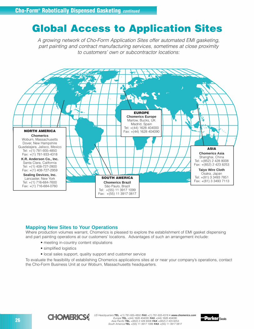
26US Headquarters TEL +(1) 781-935-4850 FAX +(1) 781-933-4318 • www.chomerics.com
Europe TEL +(44) 1628 404000 FAX +(44) 1628 404090Asia Pacific TEL +(852) 2 428 8008 FAX +(852) 2 423 8253
South America TEL +(55) 11 3917 1099 FAX +(55) 11 3917 0817
Cho-Form® Robotically Dispensed Gasketing continued
Global Access to Application SitesA growing network of Cho-Form Application Sites offer automated EMI gasketing,part painting and contract manufacturing services, sometimes at close proximity
to customers’ own or subcontractor locations:
ASIAChomerics Asia Shanghai, China
Tel: +(852) 2 428 8008Fax: +(852) 2 423 8253
Taiyo Wire ClothOsaka, Japan
Tel: +(81) 3 3493 7851Fax: +(81) 3 3493 7113
Mapping New Sites to Your OperationsWhere production volumes warrant, Chomerics is pleased to explore the establishment of EMI gasket dispensing and part painting operations at our customers’ locations. Advantages of such an arrangement include:
• meeting in-country content stipulations• simplified logistics• local sales support, quality support and customer service
To evaluate the feasibility of establishing Chomerics applications sites at or near your company’s operations, contactthe Cho-Form Business Unit at our Woburn, Massachusetts headquarters.
SOUTH AMERICAChomerics BrazilSão Paulo, Brazil
Tel: +(55) 11 3917 1099Fax: +(55) 11 3917 0817
NORTH AMERICAChomerics
Woburn, MassachusettsDover, New Hampshire
Guadalajara, Jalisco, MexicoTel: +(1) 781-935-4850Fax: +(1) 781-933-4318K.R. Anderson Co., Inc.Santa Clara, CaliforniaTel: +(1) 408-727-2800Fax: +(1) 408-727-2959Sealing Devices, Inc.Lancaster, New York
Tel: +(1) 716-684-7600Fax: +(1) 716-684-0760
EUROPEChomerics EuropeMarlow, Bucks, UK
Madrid, SpainTel: +(44) 1628 404000Fax: +(44) 1628 404090
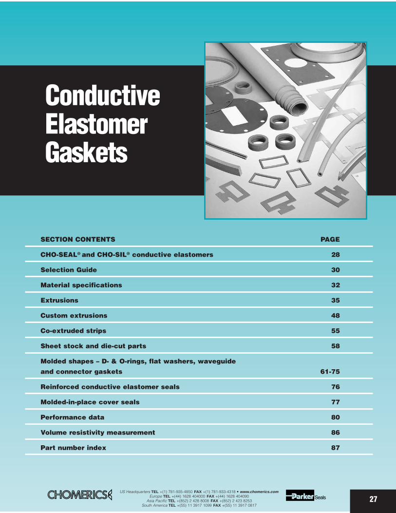
ConductiveElastomerGaskets
27
SECTION CONTENTS PAGE
CHO-SEAL® and CHO-SIL® conductive elastomers 28
Selection Guide 30
Material specifications 32
Extrusions 35
Custom extrusions 48
Co-extruded strips 55
Sheet stock and die-cut parts 58
Molded shapes – D- & O-rings, flat washers, waveguide
and connector gaskets 61-75
Reinforced conductive elastomer seals 76
Molded-in-place cover seals 77
Performance data 80
Volume resistivity measurement 86
Part number index 87
US Headquarters TEL +(1) 781-935-4850 FAX +(1) 781-933-4318 • www.chomerics.comEurope TEL +(44) 1628 404000 FAX +(44) 1628 404090
Asia Pacific TEL +(852) 2 428 8008 FAX +(852) 2 423 8253South America TEL +(55) 11 3917 1099 FAX +(55) 11 3917 0817
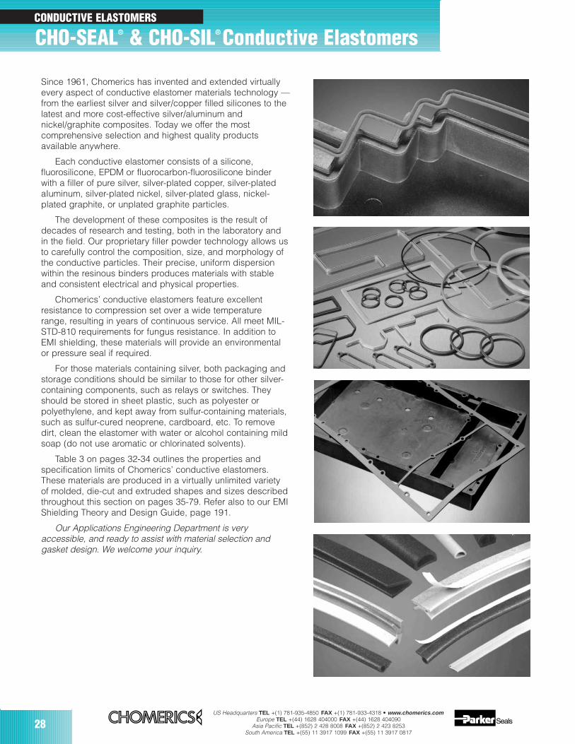
28US Headquarters TEL +(1) 781-935-4850 FAX +(1) 781-933-4318 • www.chomerics.com
Europe TEL +(44) 1628 404000 FAX +(44) 1628 404090Asia Pacific TEL +(852) 2 428 8008 FAX +(852) 2 423 8253
South America TEL +(55) 11 3917 1099 FAX +(55) 11 3917 0817
CHO-SEAL® & CHO-SIL® Conductive Elastomers
Since 1961, Chomerics has invented and extended virtuallyevery aspect of conductive elastomer materials technology —from the earliest silver and silver/copper filled silicones to thelatest and more cost-effective silver/aluminum andnickel/graphite composites. Today we offer the mostcomprehensive selection and highest quality productsavailable anywhere.
Each conductive elastomer consists of a silicone,fluorosilicone, EPDM or fluorocarbon-fluorosilicone binderwith a filler of pure silver, silver-plated copper, silver-platedaIuminum, silver-plated nickel, silver-plated glass, nickel-plated graphite, or unplated graphite particles.
The development of these composites is the result ofdecades of research and testing, both in the laboratory andin the field. Our proprietary filler powder technology allows usto carefully control the composition, size, and morphology ofthe conductive particles. Their precise, uniform dispersionwithin the resinous binders produces materials with stableand consistent electrical and physical properties.
Chomerics’ conductive elastomers feature excellentresistance to compression set over a wide temperaturerange, resulting in years of continuous service. All meet MIL-STD-810 requirements for fungus resistance. In addition toEMI shielding, these materials will provide an environmentalor pressure seal if required.
For those materials containing silver, both packaging andstorage conditions should be similar to those for other silver-containing components, such as relays or switches. Theyshould be stored in sheet plastic, such as polyester orpolyethylene, and kept away from sulfur-containing materials,such as sulfur-cured neoprene, cardboard, etc. To removedirt, clean the elastomer with water or alcohol containing mildsoap (do not use aromatic or chlorinated solvents).
Table 3 on pages 32-34 outlines the properties andspecification limits of Chomerics’ conductive elastomers.These materials are produced in a virtually unlimited varietyof molded, die-cut and extruded shapes and sizes describedthroughout this section on pages 35-79. Refer also to our EMIShielding Theory and Design Guide, page 191.
Our Applications Engineering Department is veryaccessible, and ready to assist with material selection andgasket design. We welcome your inquiry.
CONDUCTIVE ELASTOMERS
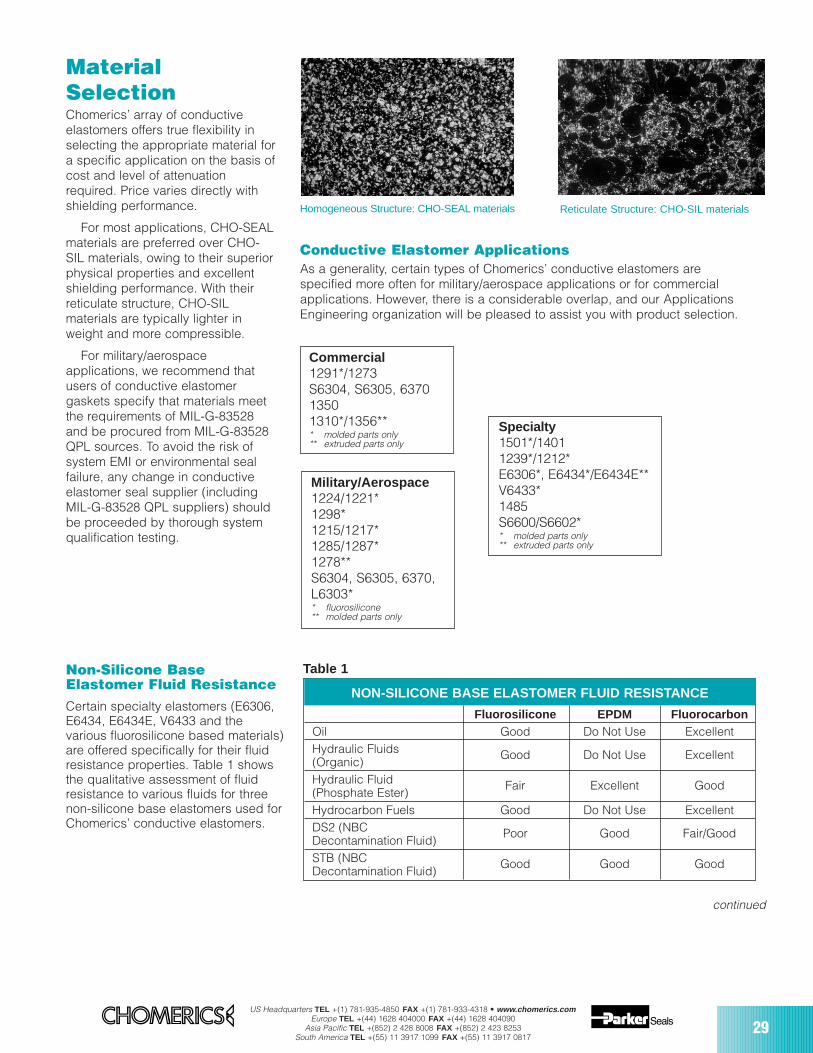
US Headquarters TEL +(1) 781-935-4850 FAX +(1) 781-933-4318 • www.chomerics.comEurope TEL +(44) 1628 404000 FAX +(44) 1628 404090
Asia Pacific TEL +(852) 2 428 8008 FAX +(852) 2 423 8253South America TEL +(55) 11 3917 1099 FAX +(55) 11 3917 0817
29
MaterialSelectionChomerics’ array of conductiveelastomers offers true flexibility inselecting the appropriate material fora specific application on the basis ofcost and level of attenuationrequired. Price varies directly withshielding performance.
For most applications, CHO-SEALmaterials are preferred over CHO-SIL materials, owing to their superiorphysical properties and excellentshielding performance. With theirreticulate structure, CHO-SILmaterials are typically lighter inweight and more compressible.
For military/aerospaceapplications, we recommend thatusers of conductive elastomergaskets specify that materials meetthe requirements of MIL-G-83528and be procured from MIL-G-83528QPL sources. To avoid the risk ofsystem EMI or environmental sealfailure, any change in conductiveelastomer seal supplier (includingMIL-G-83528 QPL suppliers) shouldbe proceeded by thorough systemqualification testing.
Homogeneous Structure: CHO-SEAL materials Reticulate Structure: CHO-SIL materials
Conductive Elastomer ApplicationsAs a generality, certain types of Chomerics’ conductive elastomers arespecified more often for military/aerospace applications or for commercialapplications. However, there is a considerable overlap, and our ApplicationsEngineering organization will be pleased to assist you with product selection.
Military/Aerospace1224/1221*1298*1215/1217*1285/1287*1278**S6304, S6305, 6370, L6303** fluorosilicone** molded parts only
Specialty1501*/14011239*/1212*E6306*, E6434*/E6434E**V6433*1485S6600/S6602** molded parts only** extruded parts only
Commercial1291*/1273S6304, S6305, 637013501310*/1356*** molded parts only** extruded parts only
Non-Silicone BaseElastomer Fluid ResistanceCertain specialty elastomers (E6306,E6434, E6434E, V6433 and thevarious fluorosilicone based materials)are offered specifically for their fluidresistance properties. Table 1 showsthe qualitative assessment of fluidresistance to various fluids for threenon-silicone base elastomers used forChomerics’ conductive elastomers.
Fluorosilicone EPDM FluorocarbonOil Good Do Not Use ExcellentHydraulic Fluids(Organic)
Good Do Not Use Excellent
Hydraulic Fluid(Phosphate Ester)
Fair Excellent Good
Hydrocarbon Fuels Good Do Not Use ExcellentDS2 (NBCDecontamination Fluid)
Poor Good Fair/Good
STB (NBCDecontamination Fluid)
Good Good Good
NON-SILICONE BASE ELASTOMER FLUID RESISTANCE
Table 1
continued
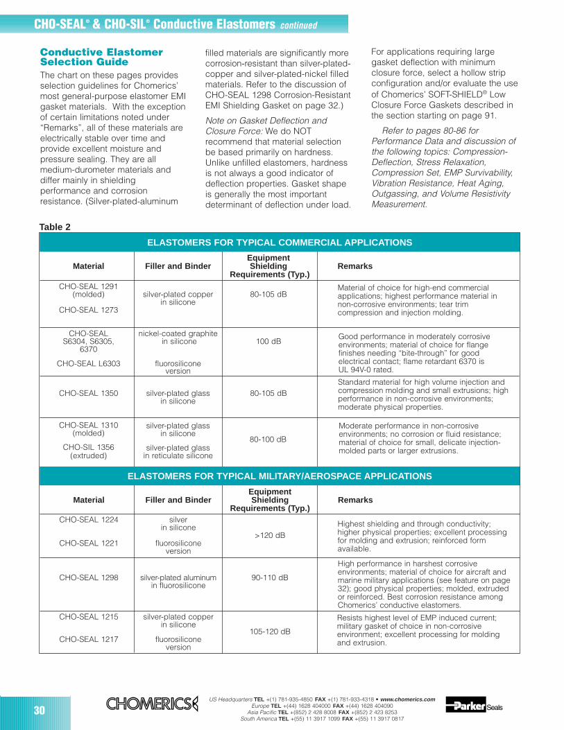
30US Headquarters TEL +(1) 781-935-4850 FAX +(1) 781-933-4318 • www.chomerics.com
Europe TEL +(44) 1628 404000 FAX +(44) 1628 404090Asia Pacific TEL +(852) 2 428 8008 FAX +(852) 2 423 8253
South America TEL +(55) 11 3917 1099 FAX +(55) 11 3917 0817
Good performance in moderately corrosiveenvironments; material of choice for flangefinishes needing “bite-through” for goodelectrical contact; flame retardant 6370 is UL 94V-0 rated.
CHO-SEAL® & CHO-SIL® Conductive Elastomers continued
Conductive ElastomerSelection GuideThe chart on these pages providesselection guidelines for Chomerics’most general-purpose elastomer EMIgasket materials. With the exceptionof certain limitations noted under“Remarks”, all of these materials areelectrically stable over time andprovide excellent moisture andpressure sealing. They are allmedium-durometer materials anddiffer mainly in shieldingperformance and corrosionresistance. (Silver-plated-aluminum
ELASTOMERS FOR TYPICAL COMMERCIAL APPLICATIONS
filled materials are significantly morecorrosion-resistant than silver-plated-copper and silver-plated-nickel filledmaterials. Refer to the discussion ofCHO-SEAL 1298 Corrosion-ResistantEMI Shielding Gasket on page 32.)
Note on Gasket Deflection andClosure Force: We do NOTrecommend that material selectionbe based primarily on hardness.Unlike unfilled elastomers, hardnessis not always a good indicator ofdeflection properties. Gasket shapeis generally the most importantdeterminant of deflection under load.
For applications requiring largegasket deflection with minimumclosure force, select a hollow stripconfiguration and/or evaluate the useof Chomerics’ SOFT-SHIELD® LowClosure Force Gaskets described inthe section starting on page 91.
Refer to pages 80-86 forPerformance Data and discussion ofthe following topics: Compression-Deflection, Stress Relaxation,Compression Set, EMP Survivability,Vibration Resistance, Heat Aging,Outgassing, and Volume ResistivityMeasurement.
Material of choice for high-end commercialapplications; highest performance material innon-corrosive environments; tear trimcompression and injection molding.
Standard material for high volume injection andcompression molding and small extrusions; highperformance in non-corrosive environments;moderate physical properties.
Moderate performance in non-corrosiveenvironments; no corrosion or fluid resistance;material of choice for small, delicate injection-molded parts or larger extrusions.
ELASTOMERS FOR TYPICAL MILITARY/AEROSPACE APPLICATIONS
Highest shielding and through conductivity;higher physical properties; excellent processingfor molding and extrusion; reinforced formavailable.
High performance in harshest corrosiveenvironments; material of choice for aircraft andmarine military applications (see feature on page32); good physical properties; molded, extruded or reinforced. Best corrosion resistance amongChomerics’ conductive elastomers.
Resists highest level of EMP induced current;military gasket of choice in non-corrosiveenvironment; excellent processing for moldingand extrusion.
EquipmentMaterial Filler and Binder Shielding Remarks
Requirements (Typ.)CHO-SEAL 1224 silver
in silicone>120 dB
CHO-SEAL 1221 fluorosiliconeversion
CHO-SEAL 1298 silver-plated aluminum 90-110 dBin fluorosilicone
CHO-SEAL 1215 silver-plated copperin silicone
105-120 dBCHO-SEAL 1217 fluorosilicone
version
Table 2
EquipmentMaterial Filler and Binder Shielding Remarks
Requirements (Typ.)CHO-SEAL 1291
(molded) silver-plated copper 80-105 dBin silicone
CHO-SEAL 1273
CHO-SEAL nickel-coated graphiteS6304, S6305, in silicone 100 dB
6370
CHO-SEAL L6303 fluorosiliconeversion
CHO-SEAL 1350 silver-plated glass 80-105 dBin silicone
CHO-SEAL 1310(molded)
silver-plated glassin silicone
CHO-SIL 1356 silver-plated glass(extruded) in reticulate silicone
80-100 dB
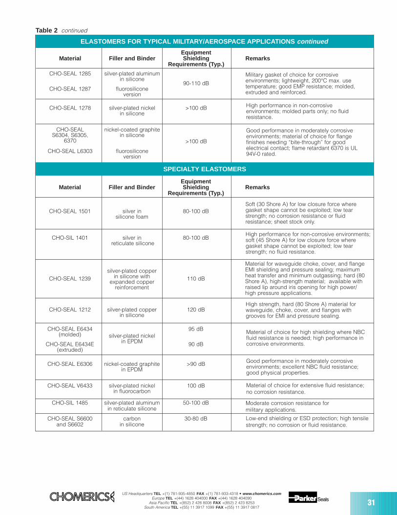
US Headquarters TEL +(1) 781-935-4850 FAX +(1) 781-933-4318 • www.chomerics.comEurope TEL +(44) 1628 404000 FAX +(44) 1628 404090
Asia Pacific TEL +(852) 2 428 8008 FAX +(852) 2 423 8253South America TEL +(55) 11 3917 1099 FAX +(55) 11 3917 0817
31
EquipmentMaterial Filler and Binder Shielding Remarks
Requirements (Typ.)
CHO-SEAL 1285 silver-plated aluminumin silicone
90-110 dBCHO-SEAL 1287 fluorosilicone
version
CHO-SEAL 1278 silver-plated nickel >100 dBin silicone
CHO-SEAL nickel-coated graphiteS6304, S6305, in silicone
6370 >100 dB
CHO-SEAL L6303 fluorosiliconeversion
ELASTOMERS FOR TYPICAL MILITARY/AEROSPACE APPLICATIONS continued
Military gasket of choice for corrosiveenvironments; lightweight, 200°C max. usetemperature; good EMP resistance; molded,extruded and reinforced.
High performance in non-corrosiveenvironments; molded parts only; no fluidresistance.
Good performance in moderately corrosiveenvironments; material of choice for flangefinishes needing “bite-through” for goodelectrical contact; flame retardant 6370 is UL94V-0 rated.
EquipmentMaterial Filler and Binder Shielding Remarks
Requirements (Typ.)
CHO-SEAL 1501 silver in 80-100 dBsilicone foam
CHO-SIL 1401 silver in 80-100 dBreticulate silicone
CHO-SEAL 1239silver-plated copper
110 dBin silicone withexpanded copper
reinforcement
CHO-SEAL 1212 silver-plated copper 120 dBin silicone
CHO-SEAL E6434 95 dB(molded) silver-plated nickel
in EPDMCHO-SEAL E6434E 90 dB(extruded)
CHO-SEAL E6306 nickel-coated graphite >90 dBin EPDM
CHO-SEAL V6433 silver-plated nickel 100 dBin fluorocarbon
CHO-SIL 1485 silver-plated aluminum 50-100 dBin reticulate silicone
CHO-SEAL S6600 carbon 30-80 dBand S6602 in silicone
SPECIALTY ELASTOMERS
Soft (30 Shore A) for low closure force wheregasket shape cannot be exploited; low tearstrength; no corrosion resistance or fluidresistance; sheet stock only.
High performance for non-corrosive environments;soft (45 Shore A) for low closure force wheregasket shape cannot be exploited; low tearstrength; no fluid resistance.
Material for waveguide choke, cover, and flangeEMI shielding and pressure sealing; maximumheat transfer and minimum outgassing; hard (80Shore A), high-strength material; available withraised lip around iris opening for high power/high pressure applications.
High strength, hard (80 Shore A) material forwaveguide, choke, cover, and flanges withgrooves for EMI and pressure sealing.
Material of choice for high shielding where NBCfluid resistance is needed; high performance incorrosive environments.
Good performance in moderately corrosiveenvironments; excellent NBC fluid resistance;good physical properties.
Material of choice for extensive fluid resistance;no corrosion resistance.
Moderate corrosion resistance formilitary applications.
Low-end shielding or ESD protection; high tensilestrength; no corrosion or fluid resistance.
Table 2 continued
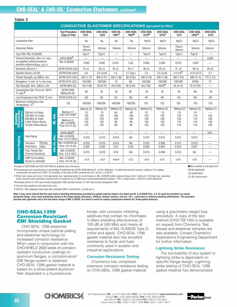
32US Headquarters TEL +(1) 781-935-4850 FAX +(1) 781-933-4318 • www.chomerics.com
Europe TEL +(44) 1628 404000 FAX +(44) 1628 404090Asia Pacific TEL +(852) 2 428 8008 FAX +(852) 2 423 8253
South America TEL +(55) 11 3917 1099 FAX +(55) 11 3917 0817
CHO-SEAL1298Corrosion-ResistantEMI Shielding Gasket
CHO-SEAL 1298 elastomerincorporates unique particle platingand elastomer technology forincreased corrosion resistance.When used in conjunction with theCHO-SHIELD 2000 series of corrosion-resistant conductive coatings onaluminum flanges, a corrosion-proofEMI flange system is obtained.CHO-SEAL 1298 gasket material isbased on a silver-plated-aluminumfiller dispersed in a fluorosilicone
binder, with corrosion inhibitingadditives that contain no chromates.It offers shielding effectiveness of100 dB at 500 MHz and meets allrequirements of MIL-G-83528 Type D(initial and aged). CHO-SEAL 1298gasket material also has excellentresistance to fluids and fuelscommonly used in aviation andindustrial applications.
Corrosion Resistance TestingChomerics has completed
extensive corrosion resistance testingon CHO-SEAL 1298 gasket material
using a gravimetric weight lossprocedure. A copy of the testmethod (CHO-TM 100) is availableon request from Chomerics. Testfixtures and elastomer samples arealso available. Contact Chomerics’Applications Engineering Departmentfor further information.
Lightning Strike ResistanceThe survivability of any system to
lightning strike is dependent onspecific flange design. Lightningstrike testing of CHO-SEAL 1298gasket material has demonstrated
a Copies of CEPS-0002 and CHO-TM-TP08 are available from Chomericsb Compression set is expressed as a percentage of deflection per ASTM D395 Method B., at 25% deflection. To determine percent recovery, subtract 1/4 of stated
compression set value from 100%. For example, in the case of 30% compression set, recover y is 92.5%.c Where two values are shown: First represents max. operating temp. for conformance to MIL-G-83528 (which requires Group A life t esting at 1.25 times max. operating
temp.) Second value represents practical limit for exposure up to 1000 hours (compressed between flanges 7-10%). Single value c onforms to both definitions.d Extruded version of 1215 was formerly designated 1250; extruded version of 1401 was formerly designated 1405.e Second value applies to extruded forms only.f CHO-SIL 1401 degrades electrically after simulated EMP current levels < 0.9 kA per in.
dB, m
in.
CONDUCTIVE ELASTOMER SPECIFICATIONS (grouped by filler)
Method (1)CHO-TM-TP08a
Method (2)MIL-G-83528
Para 4.6.12 (Q)
Method (2) Method (2) Method (1)Method (2)Method (2)
Table 3
Method (2)
Note: It may not be inferred that the same level of shielding effectiveness provided by a gasket material tested in the fixture per M IL-G-83528 Para. 4.6.12 would be provided in an actualequipment flange, since many mechanical factors of the flange design (tolerances, stiffness, fastener location, and size, etc.) could lower or enhance shielding effectiveness. This procedureprovides data applicable only to the test fixture design of MIL-G-83528, but which is useful for making comparisons between dif ferent gasket materials.
CHO-SEAL® & CHO-SIL® Conductive Elastomers continued
Method (2) Method (2) Method (2)
Not available in extruded form.NA Not Applicable (Q) Qualification(C) QC Conformance
Test Procedure CHO-SEAL CHO-SEAL CHO-SIL CHO-SEAL CHO-SEAL CHO-SEAL CHO-SEAL CHO-SEAL CHO-SEAL(Type of Test) 1221 1224 1401d 1501 1212 1215d 1217 1239 1273
Conductive Filler Ag Ag Ag Ag Ag/Cu Ag/Cu Ag/Cu Ag/Cu Ag/Cu
Elastomer Binder Fluoro- Silicone Silicone Silicone Silicone Silicone Fluoro- Silicone Siliconesilicone silicone
Type (Ref. MIL-G-83528) Type F Type E — — Type K Type A Type C Type G —
Volume Resistivity, ohm-cm, max., CEPS-0002a — — — — — — — — 0.004as supplied (without pressure- MIL-G-83528 0.002 0.002 0.010 0.03 0.005 0.004 0.010 0.007 —sensitive adhesive)Para. 4.6.11Hardness (Shore A ) ASTM D2240 (Q/C) 75 ±5 65 ±5 45 ±5 35 ±7 80 ±5 65 ±5 75 ±5 80 ±5 65 ±8
Specific Gravity (±0.25) ASTM D792 (Q/C) 4.0 3.5 ±0.45 1.6 2.7 (typ.) 3.5 3.5 ±0.45 4.1/3.8e 4.75 ±0.75 3.7
Tensile Strength, psi (MPa), min. ASTM D412 (Q/C) 250 (1.72) 300 (2.07) 200 (1.38) 80 (0.55) 400 (2.76) 200 (1.38) 180 (1.24) 600 (4.14) 175 (1.21)
Elongation, % min. or % min./max. ASTM D412 (Q/C) 100/300 200/500 75 NA 100/300 100/300 100/300 20/NA 75
Tear Strength, lb/in. (kN/m), min. ASTM D624 (Q) 40 (7.00) 50 (8.75) 20 (3.50) 20 (3.50) 40 (7.00) 40/25e 35 (6.13) 70 (12.25) —
Compression Set, 70 hrs @ 100°C, ASTM D395 60 45 35 80 35 32 35 NA 32% max.b Method B (Q)
LowTemperature Flex TR10,°C,min. ASTM D1329 (Q) –65 -65 –55 NA –45 –65 –55 NA –65
Maximum Continuous Use (Q) 160/200 160/200 160/200 160/200 125 125 125 125 125Temperature, °Cc
200 kHz (H Field) 70 70 60 60 70 70 70 70 —100 MHz (E Field) 120 120 100 100 120 120 120 110 100500 MHz (E Field) 120 120 100 100 120 120 120 110 100 2 GHz (Plane Wave) 120 120 90 90 120 120 115 110 10010 GHz (Plane Wave) 120 120 80 80 120 120 110 110 100
CEPS-0002a — — — — — — — — 0.01Heat Aging MIL-G-83528 0.010 0.010 0.015 NA 0.010 0.010 0.015 0.010 —Para. 4.6.15 (Q/C)
Vibration During MIL-G-83528 (Q) 0.010 0.010 0.015 NA 0.010 0.006 0.015 0.010 —Resistance After Para. 4.6.13 (Q) 0.002 0.002 0.01 0.03 0.005 0.004 0.010 0.007 —Post Tensile Set MIL-G-83528 0.010 0.010 0.02 NA 0.010 0.008 0.015 NA —Volume Resistivity Para. 4.6.9 (Q/C)
EMP Survivability, MIL-G-83528 >0.9 >0.9 note f >0.3 >0.9 >0.9 >0.9 >0.9 —kA per in. perimeter Para. 4.6.16 (Q)
Shie
ldin
gEf
fect
iven
ess
(see
Not
e be
low
)
ohm
-cm
, max
.
Elec
tric
al S
tabi
lity

US Headquarters TEL +(1) 781-935-4850 FAX +(1) 781-933-4318 • www.chomerics.comEurope TEL +(44) 1628 404000 FAX +(44) 1628 404090
Asia Pacific TEL +(852) 2 428 8008 FAX +(852) 2 423 8253South America TEL +(55) 11 3917 1099 FAX +(55) 11 3917 0817
33
Comparison ofcorrosion resultsobtained fromCHO-SEAL 1298conductiveelastomer (left)and pure silver-filled elastomer(right) mated withchromatedaluminum for 168hours of salt fogexposure.
survivability beyond 5 kA/in. Testdata is available on request.
Ordering InformationCHO-SEAL 1298 gaskets are
available in all standard formsincluding molded, die-cut andextruded. The material is alsoavailable reinforced with DupontDacron® fabric, woven wire meshand/or 3M Nextel® fabric. See page76 for more information.
For more information on corrosioncontrol, refer to the EMI ShieldingTheory and Design Guide, whichbegins on page 191.
Table 3 continued
Test Procedure CHO-SEAL CHO-SEAL CHO-SEAL CHO-SEAL CHO-SEAL CHO-SEAL CHO-SEAL CHO-SEAL CHO-SIL CHO-SEAL(Type of Test) 1291 1278 V6433 E6434 E6434E• 1285 1287 1298 1485 1310
Conductive Filler Ag/Cu Ag/Ni Ag/Ni Ag/Ni Ag/Ni Ag/Al Ag/Al Passivated Ag/Al Ag/GlassAg/Al
Elastomer Binder Silicone Silicone Fluorocarbon/ EPDM EPDM Silicone Fluoro- Fluoro- Silicone SiliconeFluorosilicone silicone silicone
Type (Ref. MIL-G-83528) — Type L — — — Type B Type D Type D — —
Volume Resistivity, ohm-cm, max., CEPS-0002a 0.004 — — — — — — — — 0.01as supplied (without pressure- MIL-G-83528 — 0.005 0.006 0.006 0.05 0.008 0.012 0.012 0.02 —sensitive adhesive) Para. 4.6.11Hardness (Shore A) ASTM D2240 (Q/C) 70 ±5 75 ±5 85 ±7 75 ±7 80 ±7 65 ±5 70 ±5 70 ±5 60 ±5 70 ±10
Specific Gravity (±0.25) ASTM D792 (Q/C) 3.45 4.0 4.8 3.9 3.8 1.9 2.0 2.0 1.7 1.8
Tensile Strength, psi (MPa), min. ASTM D412 (Q/C) 175 (1.21) 200 (1.38) 400 (2.76) 200 (1.38) 200 (1.38) 200 (1.38) 180 (1.24) 180 (1.24) 180 (1.24) 200 (1.38)
Elongation, % min. or % min./max. ASTM D412 (Q/C) 75 100/300 50 200 100 100/300 60/260 60/260 100 100
Tear Strength, lb/in. (kN/m), min. ASTM D624 (Q) — 30 (5.25) 70 (12.25) 75 (13.13) 70 (12.25) 30 (5.25) 35 (6.13) 35 (6.13) 30 (5.25)
Compression Set, 70 hrs @ 100°C, ASTM D395 32 32 45 40 40 32 30 30 30 35% max.b Method B (Q)
LowTemperature Flex TR10,°C,min. ASTM D1329 (Q) –45 –55 –25 –45 –45 –65 -55 –55 –40 –40
Maximum Continuous Use (Q) 125 125 200 100 100 160/200 160/200 160/200 85 160Temperature, °Cc
200 kHz (H Field) — 70 — — — 60 55 55 50 —100 MHz (E Field) 100 120 105 105 90 115 110 110 100 100500 MHz (E Field) 100 120 100 100 90 110 100 100 100 100 2 GHz (Plane Wave) 100 115 90 85 90 105 95 95 90 9010 GHz (Plane Wave) 100 110 90 85 90 100 90 90 80 80
CEPS-0002a 0.008 — — — — — — — — 0.01Heat Aging MIL-G-83528 — 0.010 0.008g 0.0125h 0.05h 0.010 0.015 0.015 0.06g —Para. 4.6.15 (Q/C)
Vibration During MIL-G-83528 (Q) — 0.010 NA NA NA 0.012 0.015 0.015 0.06 —Resistance After Para. 4.6.13 (Q) — 0.005 NA NA 0.05 0.008 0.012 0.012 0.02 —Post Tensile Set MIL-G-83528 — 0.010 — — NA 0.015 0.015 0.015 NA —Volume Resistivity Para. 4.6.9 (Q/C)
EMP Survivability, MIL-G-83528 — >0.9 NA NA — >0.9 >0.9 >0.9 >0.3 —kA per in. perimeter Para. 4.6.16 (Q)
CONDUCTIVE ELASTOMER SPECIFICATIONS (grouped by filler)
Shie
ldin
gEf
fect
iven
ess
(see
Not
e be
low
)El
ectr
ical
Sta
bilit
y
Method (1)CHO-TM-TP08a
Method (2)MIL-G-83528
Para 4.6.12 (Q)
Method (2) Method (1)Method (2)Method (2) Method (2) Method (2) Method (2) Method (2) Method (1)
Note: It may not be inferred that the same level of shielding effectiveness provided by a gasket material tested in the fixture per M IL-G-83528 Para. 4.6.12 would be provided in an actualequipment flange, since many mechanical factors of the flange design (tolerances, stiffness, fastener location, and size, etc.) could lower or enhance shielding effectiveness. This procedureprovides data applicable only to the test fixture design of MIL-G-83528, but which is useful for making comparisons between dif ferent gasket materials.
a Copies of CEPS-0002 and CHO-TM-TP08 are available from Chomericsb Compression set is expressed as a percentage of deflection per ASTM D395 Method B., at 25% deflection. To determine percent recovery, subtract 1/4 of stated
compression set value from 100%. For example, in the case of 30% compression set, recover y is 92.5%.c Where two values are shown: First represents max. operating temp. for conformance to MIL-G-83528 (which requires Group A life t esting at 1.25 times max. operating
temp.) Second value represents practical limit for exposure up to 1000 hours (compressed between flanges 7-10%). Single value c onforms to both definitions.g Heat aging condition: 200°C/48 hrs.h Heat aging condition: 100°C/48 hrs. continued
ohm
-cm
, max
.
Method (1)
Not available in extruded form.
• Not available in sheet or molded form.NA Not Applicable(Q) Qualification (C) QC Conformance
dB, m
in.
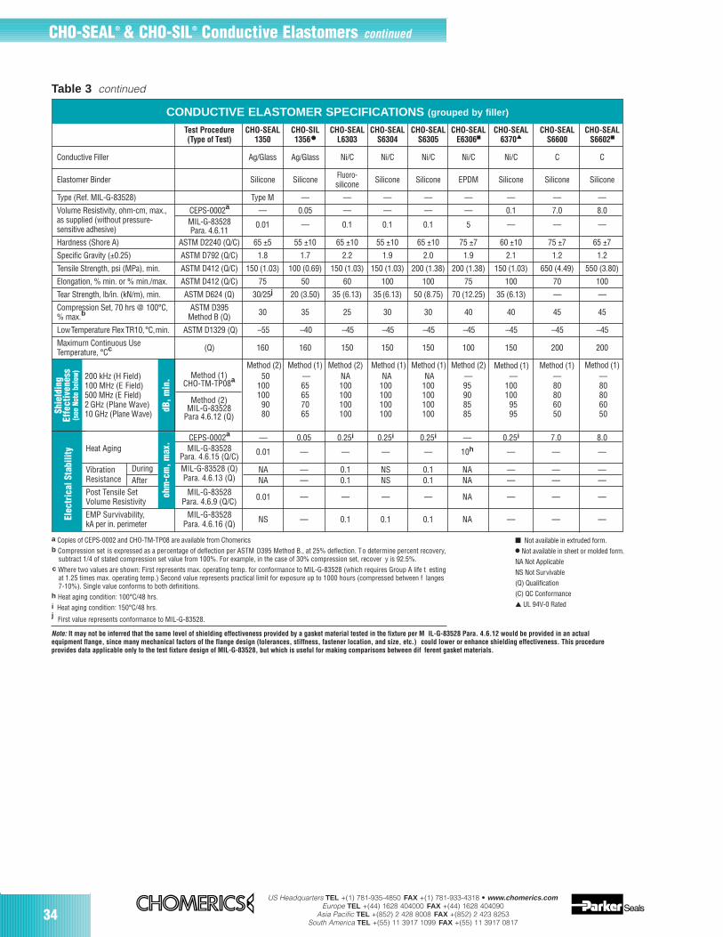
34US Headquarters TEL +(1) 781-935-4850 FAX +(1) 781-933-4318 • www.chomerics.com
Europe TEL +(44) 1628 404000 FAX +(44) 1628 404090Asia Pacific TEL +(852) 2 428 8008 FAX +(852) 2 423 8253
South America TEL +(55) 11 3917 1099 FAX +(55) 11 3917 0817
a Copies of CEPS-0002 and CHO-TM-TP08 are available from Chomericsb Compression set is expressed as a percentage of deflection per ASTM D395 Method B., at 25% deflection. To determine percent recovery,
subtract 1/4 of stated compression set value from 100%. For example, in the case of 30% compression set, recover y is 92.5%.c Where two values are shown: First represents max. operating temp. for conformance to MIL-G-83528 (which requires Group A life t esting
at 1.25 times max. operating temp.) Second value represents practical limit for exposure up to 1000 hours (compressed between f langes 7-10%). Single value conforms to both definitions.
h Heat aging condition: 100°C/48 hrs.i Heat aging condition: 150°C/48 hrs.j First value represents conformance to MIL-G-83528.
Note: It may not be inferred that the same level of shielding effectiveness provided by a gasket material tested in the fixture per M IL-G-83528 Para. 4.6.12 would be provided in an actualequipment flange, since many mechanical factors of the flange design (tolerances, stiffness, fastener location, and size, etc.) could lower or enhance shielding effectiveness. This procedureprovides data applicable only to the test fixture design of MIL-G-83528, but which is useful for making comparisons between dif ferent gasket materials.
Table 3 continued
dB, m
in.
Test Procedure CHO-SEAL CHO-SIL CHO-SEAL CHO-SEAL CHO-SEAL CHO-SEAL CHO-SEAL CHO-SEAL CHO-SEAL(Type of Test) 1350 1356• L6303 S6304 S6305 E6306 6370 S6600 S6602
Conductive Filler Ag/Glass Ag/Glass Ni/C Ni/C Ni/C Ni/C Ni/C C C
Elastomer Binder Silicone Silicone Fluoro- Silicone Silicone EPDM Silicone Silicone Siliconesilicone
Type (Ref. MIL-G-83528) Type M — — — — — — — —
Volume Resistivity, ohm-cm, max., CEPS-0002a — 0.05 — — — — 0.1 7.0 8.0as supplied (without pressure- MIL-G-83528 0.01 — 0.1 0.1 0.1 5 — — —sensitive adhesive) Para. 4.6.11Hardness (Shore A) ASTM D2240 (Q/C) 65 ±5 55 ±10 65 ±10 55 ±10 65 ±10 75 ±7 60 ±10 75 ±7 65 ±7
Specific Gravity (±0.25) ASTM D792 (Q/C) 1.8 1.7 2.2 1.9 2.0 1.9 2.1 1.2 1.2
Tensile Strength, psi (MPa), min. ASTM D412 (Q/C) 150 (1.03) 100 (0.69) 150 (1.03) 150 (1.03) 200 (1.38) 200 (1.38) 150 (1.03) 650 (4.49) 550 (3.80)
Elongation, % min. or % min./max. ASTM D412 (Q/C) 75 50 60 100 100 75 100 70 100
Tear Strength, lb/in. (kN/m), min. ASTM D624 (Q) 30/25j 20 (3.50) 35 (6.13) 35 (6.13) 50 (8.75) 70 (12.25) 35 (6.13) — —
Compression Set, 70 hrs @ 100°C, ASTM D395 30 35 25 30 30 40 40 45 45% max.b Method B (Q)
LowTemperature Flex TR10,°C,min. ASTM D1329 (Q) –55 –40 –45 –45 –45 –45 –45 –45 –45
Maximum Continuous Use (Q) 160 160 150 150 150 100 150 200 200Temperature, °Cc
200 kHz (H Field) 50 — NA NA NA — — — —100 MHz (E Field) 100 65 100 100 100 95 100 80 80500 MHz (E Field) 100 65 100 100 100 90 100 80 80 2 GHz (Plane Wave) 90 70 100 100 100 85 95 60 6010 GHz (Plane Wave) 80 65 100 100 100 85 95 50 50
CEPS-0002a — 0.05 0.25i 0.25i 0.25i — 0.25i 7.0 8.0Heat Aging MIL-G-83528 0.01 — — — — 10h — — —Para. 4.6.15 (Q/C)
Vibration During MIL-G-83528 (Q) NA — 0.1 NS 0.1 NA — — —Resistance After Para. 4.6.13 (Q) NA — 0.1 NS 0.1 NA — — —Post Tensile Set MIL-G-83528 0.01 — — — — NA — — —Volume Resistivity Para. 4.6.9 (Q/C)
EMP Survivability, MIL-G-83528 NS — 0.1 0.1 0.1 NA — — —kA per in. perimeter Para. 4.6.16 (Q)
CONDUCTIVE ELASTOMER SPECIFICATIONS (grouped by filler)
Shie
ldin
gEf
fect
iven
ess
(see
Not
e be
low
)El
ectr
ical
Sta
bilit
y
Method (1)CHO-TM-TP08a
Method (2)MIL-G-83528
Para 4.6.12 (Q)
Method (2) Method (1) Method (1)Method (1)Method (2) Method (2) Method (1) Method (1) Method (1)
CHO-SEAL® & CHO-SIL® Conductive Elastomers continued
Not available in extruded form.
• Not available in sheet or molded form.NA Not ApplicableNS Not Survivable(Q) Qualification (C) QC Conformance UL 94V-0 Rated
ohm
-cm
, max
.
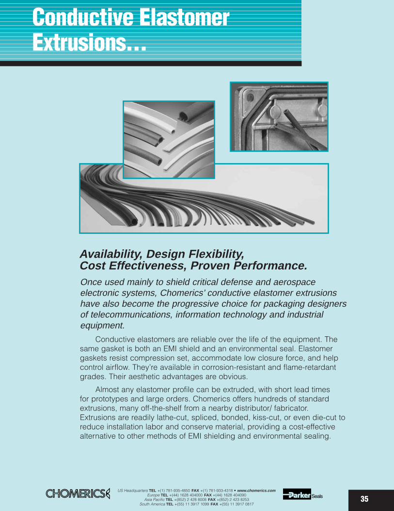
35
Availability, Design Flexibility, Cost Effectiveness, Proven Performance. Once used mainly to shield critical defense and aerospace electronic systems, Chomerics’ conductive elastomer extrusionshave also become the progressive choice for packaging designersof telecommunications, information technology and industrialequipment.
Conductive elastomers are reliable over the life of the equipment. Thesame gasket is both an EMI shield and an environmental seal. Elastomergaskets resist compression set, accommodate low closure force, and helpcontrol airflow. They’re available in corrosion-resistant and flame-retardantgrades. Their aesthetic advantages are obvious.
Almost any elastomer profile can be extruded, with short lead times for prototypes and large orders. Chomerics offers hundreds of standardextrusions, many off-the-shelf from a nearby distributor/ fabricator.Extrusions are readily lathe-cut, spliced, bonded, kiss-cut, or even die-cut toreduce installation labor and conserve material, providing a cost-effectivealternative to other methods of EMI shielding and environmental sealing.
Conductive ElastomerExtrusions...
US Headquarters TEL +(1) 781-935-4850 FAX +(1) 781-933-4318 • www.chomerics.comEurope TEL +(44) 1628 404000 FAX +(44) 1628 404090
Asia Pacific TEL +(852) 2 428 8008 FAX +(852) 2 423 8253South America TEL +(55) 11 3917 1099 FAX +(55) 11 3917 0817
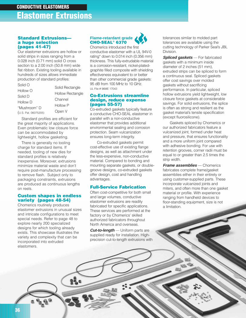
US Headquarters TEL +(1) 781-935-4850 FAX +(1) 781-933-4318 • www.chomerics.comEurope TEL +(44) 1628 404000 FAX +(44) 1628 404090
Asia Pacific TEL +(852) 2 428 8008 FAX +(852) 2 423 8253South America TEL +(55) 11 3917 1099 FAX +(55) 11 3917 0817
Elastomer Extrusions
36
Standard Extrusions—a huge selection (pages 41-47)Our elastomer extrusions are hollow orsolid strips in sizes ranging from a0.028 inch (0.71 mm) solid O crosssection to a 2.00 inch (50.8 mm) wideflat ribbon. Existing tooling available inhundreds of sizes allows immediateproduction of standard profiles:
Solid O
Hollow O
Solid D
Hollow D
“Mushroom” D (U.S. Pat. 06075205)
Standard profiles are efficient forthe great majority of applications.Even problematic low closure forcecan be accommodated bylightweight, hollow gasketing.
There is generally no toolingcharge for standard items. Ifneeded, tooling of new dies forstandard profiles is relativelyinexpensive. Moreover, extrusionsminimize material waste and don’trequire post-manufacture processingto remove flash. Subject only topackaging constraints, extrusionsare produced as continuous lengthson reels.
Custom shapes in endlessvariety (pages 48-54)Chomerics routinely produceselastomer extrusions in unusual sizesand intricate configurations to meetspecial needs. Refer to page 48 toexplore nearly 200 specializeddesigns for which tooling alreadyexists. This showcase illustrates thevariety and complexity that can beincorporated into extrudedelastomers.
CONDUCTIVE ELASTOMERS
Solid Rectangle
Hollow Rectangle
Channel
Hollow P
Open V
Flame-retardant gradeCHO-SEAL® 6370Chomerics introduced the firstconductive elastomer with a UL 94V-0rating* down to 0.014 inch (0.356 mm)thickness. This fully-extrudable materialis a corrosion-resistant, nickel-plated-graphite filled composite with shieldingeffectiveness equivalent to or betterthan other commercial grade gaskets:95 dB from 100 MHz to 10 GHz.UL File # 96ME 17043
Co-Extrusions streamlinedesign, reduce expense(pages 55-57)Co-extruded gaskets typically featurea conductive CHO-SEAL elastomer inparallel with a non-conductiveelastomer that provides additionalenvironmental sealing and corrosionprotection. Seam vulcanizationensures long-term integrity.
Co-extruded gaskets permit cost-effective use of existing flangedesigns, as well as attachment underthe less-expensive, non-conductivematerial. Compared to bonding andmounting separate gaskets, or double-groove designs, co-extruded gasketsoffer design, cost and handlingadvantages.
Full-Service FabricationOften cost-competitive for both smalland large volumes, conductiveelastomer extrusions are readilyfabricated for specific applications.These services are performed at thefactory or by Chomerics’ skilledauthorized fabricators throughoutNorth America and overseas.
Cut-to-length — Uniform parts aresupplied ready for installation. High-precision cut-to-length extrusions with
tolerances similar to molded parttolerances are available using thecutting technology of Parker Seal’s JBLDivision.
Spliced gaskets — For fabricatedgaskets with a minimum insidediameter of 2 inches (51 mm),extruded strips can be spliced to forma continuous seal. Spliced gasketsoffer cost savings over moldedgaskets without sacrificingperformance. In particular, splicedhollow extrusions yield lightweight, lowclosure force gaskets at considerablesavings. For solid extrusions, the spliceis often as strong and resilient as thegasket material’s tensile specification(except fluorosilicone).
Gaskets spliced by Chomerics orour authorized fabricators feature avulcanized joint, formed under heatand pressure, that ensures functionalityand a more uniform joint comparedwith adhesive bonding. For use withretention grooves, corner radii must beequal to or greater than 2.5 times thestrip width.
Frame assemblies — Chomericsfabricates complete frame/gasketassemblies either in their entirety orusing customer-supplied parts. Theseincorporate vulcanized joints andmiters, and often more than one gasketmaterial or profile. With experienceranging from handheld devices tofloor-standing equipment, size is not a limitation.
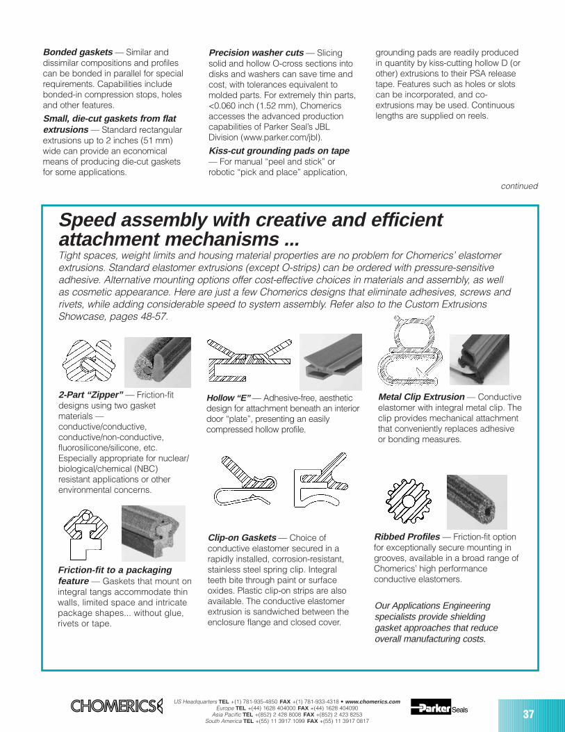
US Headquarters TEL +(1) 781-935-4850 FAX +(1) 781-933-4318 • www.chomerics.comEurope TEL +(44) 1628 404000 FAX +(44) 1628 404090
Asia Pacific TEL +(852) 2 428 8008 FAX +(852) 2 423 8253South America TEL +(55) 11 3917 1099 FAX +(55) 11 3917 0817
37
Bonded gaskets — Similar anddissimilar compositions and profilescan be bonded in parallel for specialrequirements. Capabilities includebonded-in compression stops, holesand other features.
Small, die-cut gaskets from flatextrusions — Standard rectangularextrusions up to 2 inches (51 mm)wide can provide an economicalmeans of producing die-cut gasketsfor some applications.
Precision washer cuts — Slicingsolid and hollow O-cross sections intodisks and washers can save time andcost, with tolerances equivalent tomolded parts. For extremely thin parts,<0.060 inch (1.52 mm), Chomericsaccesses the advanced productioncapabilities of Parker Seal’s JBLDivision (www.parker.com/jbl).
Kiss-cut grounding pads on tape— For manual “peel and stick” orrobotic “pick and place” application,
grounding pads are readily producedin quantity by kiss-cutting hollow D (orother) extrusions to their PSA releasetape. Features such as holes or slotscan be incorporated, and co-extrusions may be used. Continuouslengths are supplied on reels.
Speed assembly with creative and efficientattachment mechanisms ...
2-Part “Zipper” — Friction-fitdesigns using two gasketmaterials —conductive/conductive, conductive/non-conductive,fluorosilicone/silicone, etc.Especially appropriate for nuclear/biological/chemical (NBC)resistant applications or otherenvironmental concerns.
Friction-fit to a packaging feature — Gaskets that mount onintegral tangs accommodate thinwalls, limited space and intricatepackage shapes... without glue,rivets or tape.
Hollow “E” — Adhesive-free, aestheticdesign for attachment beneath an interiordoor “plate”, presenting an easilycompressed hollow profile.
Clip-on Gaskets — Choice ofconductive elastomer secured in arapidly installed, corrosion-resistant,stainless steel spring clip. Integralteeth bite through paint or surfaceoxides. Plastic clip-on strips are alsoavailable. The conductive elastomerextrusion is sandwiched between theenclosure flange and closed cover.
Metal Clip Extrusion — Conductiveelastomer with integral metal clip. Theclip provides mechanical attachmentthat conveniently replaces adhesiveor bonding measures.
Ribbed Profiles — Friction-fit optionfor exceptionally secure mounting ingrooves, available in a broad range ofChomerics’ high performanceconductive elastomers.
Our Applications Engineering specialists provide shielding gasket approaches that reduce overall manufacturing costs.
continued
Tight spaces, weight limits and housing material properties are no problem for Chomerics’ elastomerextrusions. Standard elastomer extrusions (except O-strips) can be ordered with pressure-sensitiveadhesive. Alternative mounting options offer cost-effective choices in materials and assembly, as well as cosmetic appearance. Here are just a few Chomerics designs that eliminate adhesives, screws andrivets, while adding considerable speed to system assembly. Refer also to the Custom ExtrusionsShowcase, pages 48-57.
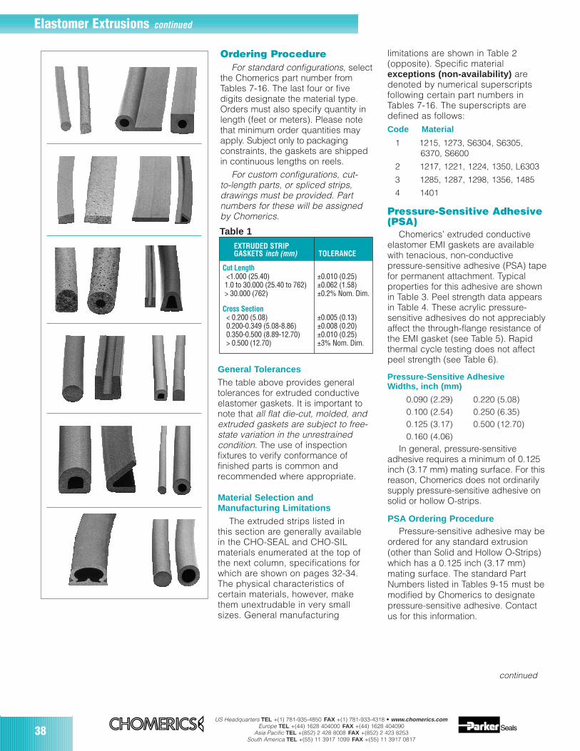
38US Headquarters TEL +(1) 781-935-4850 FAX +(1) 781-933-4318 • www.chomerics.com
Europe TEL +(44) 1628 404000 FAX +(44) 1628 404090Asia Pacific TEL +(852) 2 428 8008 FAX +(852) 2 423 8253
South America TEL +(55) 11 3917 1099 FAX +(55) 11 3917 0817
EXTRUDED STRIPGASKETS inch (mm) TOLERANCE
Cut Length<1.000 (25.40) ±0.010 (0.25)1.0 to 30.000 (25.40 to 762) ±0.062 (1.58)> 30.000 (762) ±0.2% Nom. Dim.
Cross Section< 0.200 (5.08) ±0.005 (0.13)0.200-0.349 (5.08-8.86) ±0.008 (0.20)0.350-0.500 (8.89-12.70) ±0.010 (0.25)> 0.500 (12.70) ±3% Nom. Dim.
Table 1
Ordering ProcedureFor standard configurations, select
the Chomerics part number fromTables 7-16. The last four or fivedigits designate the material type.Orders must also specify quantity inlength (feet or meters). Please notethat minimum order quantities mayapply. Subject only to packagingconstraints, the gaskets are shippedin continuous lengths on reels.
For custom configurations, cut-to-length parts, or spliced strips,drawings must be provided. Partnumbers for these will be assignedby Chomerics.
General TolerancesThe table above provides generaltolerances for extruded conductiveelastomer gaskets. It is important tonote that all flat die-cut, molded, andextruded gaskets are subject to free-state variation in the unrestrainedcondition. The use of inspectionfixtures to verify conformance offinished parts is common andrecommended where appropriate.
Elastomer Extrusions continued
Material Selection andManufacturing Limitations
The extruded strips listed inthis section are generally availablein the CHO-SEAL and CHO-SILmaterials enumerated at the top ofthe next column, specifications forwhich are shown on pages 32-34.The physical characteristics ofcertain materials, however, makethem unextrudable in very smallsizes. General manufacturing
limitations are shown in Table 2(opposite). Specific materialexceptions (non-availability) aredenoted by numerical superscriptsfollowing certain part numbers inTables 7-16. The superscripts aredefined as follows:Code Material
1 1215, 1273, S6304, S6305, 6370, S6600
2 1217, 1221, 1224, 1350, L6303
3 1285, 1287, 1298, 1356, 1485
4 1401
Pressure-Sensitive Adhesive(PSA)
Chomerics’ extruded conductiveelastomer EMI gaskets are availablewith tenacious, non-conductivepressure-sensitive adhesive (PSA) tapefor permanent attachment. Typicalproperties for this adhesive are shownin Table 3. Peel strength data appearsin Table 4. These acrylic pressure-sensitive adhesives do not appreciablyaffect the through-flange resistance ofthe EMI gasket (see Table 5). Rapidthermal cycle testing does not affectpeel strength (see Table 6).
Pressure-Sensitive AdhesiveWidths, inch (mm)
0.090 (2.29) 0.220 (5.08)0.100 (2.54) 0.250 (6.35)0.125 (3.17) 0.500 (12.70)0.160 (4.06)
In general, pressure-sensitive adhesive requires a minimum of 0.125inch (3.17 mm) mating surface. For thisreason, Chomerics does not ordinarilysupply pressure-sensitive adhesive onsolid or hollow O-strips.
continued
PSA Ordering ProcedurePressure-sensitive adhesive may be
ordered for any standard extrusion(other than Solid and Hollow O-Strips)which has a 0.125 inch (3.17 mm)mating surface. The standard PartNumbers listed in Tables 9-15 must bemodified by Chomerics to designatepressure-sensitive adhesive. Contactus for this information.
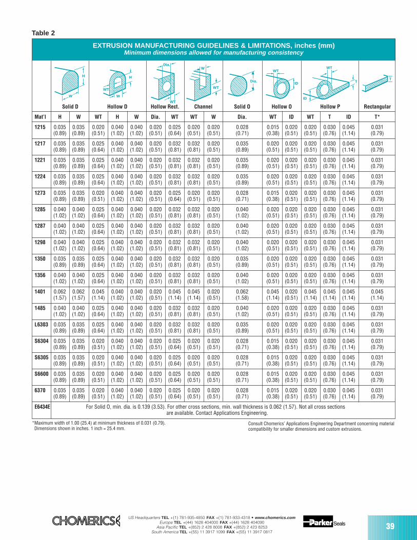
US Headquarters TEL +(1) 781-935-4850 FAX +(1) 781-933-4318 • www.chomerics.comEurope TEL +(44) 1628 404000 FAX +(44) 1628 404090
Asia Pacific TEL +(852) 2 428 8008 FAX +(852) 2 423 8253South America TEL +(55) 11 3917 1099 FAX +(55) 11 3917 0817
39
Consult Chomerics’ Applications Engineering Department concerning materialcompatibility for smaller dimensions and custom extrusions.
*Maximum width of 1.00 (25.4) at minimum thickness of 0.031 (0.79).Dimensions shown in inches. 1 inch = 25.4 mm.
Table 2
H
W
H
W
WT
WT
Dia.W
WT
Dia.
ID
WT
T
ID
WT
T
EXTRUSION MANUFACTURING GUIDELINES & LIMITATIONS, inches (mm)Minimum dimensions allowed for manufacturing consistency
Solid D Hollow D Hollow Rect. Channel Solid O Hollow O Hollow P Rectangular
Mat’l H W WT H W Dia. WT WT W Dia. WT ID WT T ID T*
1215 0.035 0.035 0.020 0.040 0.040 0.020 0.025 0.020 0.020 0.028 0.015 0.020 0.020 0.030 0.045 0.031(0.89) (0.89) (0.51) (1.02) (1.02) (0.51) (0.64) (0.51) (0.51) (0.71) (0.38) (0.51) (0.51) (0.76) (1.14) (0.79)
1217 0.035 0.035 0.025 0.040 0.040 0.020 0.032 0.032 0.020 0.035 0.020 0.020 0.020 0.030 0.045 0.031(0.89) (0.89) (0.64) (1.02) (1.02) (0.51) (0.81) (0.81) (0.51) (0.89) (0.51) (0.51) (0.51) (0.76) (1.14) (0.79)
1221 0.035 0.035 0.025 0.040 0.040 0.020 0.032 0.032 0.020 0.035 0.020 0.020 0.020 0.030 0.045 0.031(0.89) (0.89) (0.64) (1.02) (1.02) (0.51) (0.81) (0.81) (0.51) (0.89) (0.51) (0.51) (0.51) (0.76) (1.14) (0.79)
1224 0.035 0.035 0.025 0.040 0.040 0.020 0.032 0.032 0.020 0.035 0.020 0.020 0.020 0.030 0.045 0.031(0.89) (0.89) (0.64) (1.02) (1.02) (0.51) (0.81) (0.81) (0.51) (0.89) (0.51) (0.51) (0.51) (0.76) (1.14) (0.79)
1273 0.035 0.035 0.020 0.040 0.040 0.020 0.025 0.020 0.020 0.028 0.015 0.020 0.020 0.030 0.045 0.031(0.89) (0.89) (0.51) (1.02) (1.02) (0.51) (0.64) (0.51) (0.51) (0.71) (0.38) (0.51) (0.51) (0.76) (1.14) (0.79)
1285 0.040 0.040 0.025 0.040 0.040 0.020 0.032 0.032 0.020 0.040 0.020 0.020 0.020 0.030 0.045 0.031(1.02) (1.02) (0.64) (1.02) (1.02) (0.51) (0.81) (0.81) (0.51) (1.02) (0.51) (0.51) (0.51) (0.76) (1.14) (0.79)
1287 0.040 0.040 0.025 0.040 0.040 0.020 0.032 0.032 0.020 0.040 0.020 0.020 0.020 0.030 0.045 0.031(1.02) (1.02) (0.64) (1.02) (1.02) (0.51) (0.81) (0.81) (0.51) (1.02) (0.51) (0.51) (0.51) (0.76) (1.14) (0.79)
1298 0.040 0.040 0.025 0.040 0.040 0.020 0.032 0.032 0.020 0.040 0.020 0.020 0.020 0.030 0.045 0.031(1.02) (1.02) (0.64) (1.02) (1.02) (0.51) (0.81) (0.81) (0.51) (1.02) (0.51) (0.51) (0.51) (0.76) (1.14) (0.79)
1350 0.035 0.035 0.025 0.040 0.040 0.020 0.032 0.032 0.020 0.035 0.020 0.020 0.020 0.030 0.045 0.031(0.89) (0.89) (0.64) (1.02) (1.02) (0.51) (0.81) (0.81) (0.51) (0.89) (0.51) (0.51) (0.51) (0.76) (1.14) (0.79)
1356 0.040 0.040 0.025 0.040 0.040 0.020 0.032 0.032 0.020 0.040 0.020 0.020 0.020 0.030 0.045 0.031(1.02) (1.02) (0.64) (1.02) (1.02) (0.51) (0.81) (0.81) (0.51) (1.02) (0.51) (0.51) (0.51) (0.76) (1.14) (0.79)
1401 0.062 0.062 0.045 0.040 0.040 0.020 0.045 0.045 0.020 0.062 0.045 0.020 0.045 0.045 0.045 0.045(1.57) (1.57) (1.14) (1.02) (1.02) (0.51) (1.14) (1.14) (0.51) (1.58) (1.14) (0.51) (1.14) (1.14) (1.14) (1.14)
1485 0.040 0.040 0.025 0.040 0.040 0.020 0.032 0.032 0.020 0.040 0.020 0.020 0.020 0.030 0.045 0.031(1.02) (1.02) (0.64) (1.02) (1.02) (0.51) (0.81) (0.81) (0.51) (1.02) (0.51) (0.51) (0.51) (0.76) (1.14) (0.79)
L6303 0.035 0.035 0.025 0.040 0.040 0.020 0.032 0.032 0.020 0.035 0.020 0.020 0.020 0.030 0.045 0.031(0.89) (0.89) (0.64) (1.02) (1.02) (0.51) (0.81) (0.81) (0.51) (0.89) (0.51) (0.51) (0.51) (0.76) (1.14) (0.79)
S6304 0.035 0.035 0.020 0.040 0.040 0.020 0.025 0.020 0.020 0.028 0.015 0.020 0.020 0.030 0.045 0.031(0.89) (0.89) (0.51) (1.02) (1.02) (0.51) (0.64) (0.51) (0.51) (0.71) (0.38) (0.51) (0.51) (0.76) (1.14) (0.79)
S6305 0.035 0.035 0.020 0.040 0.040 0.020 0.025 0.020 0.020 0.028 0.015 0.020 0.020 0.030 0.045 0.031(0.89) (0.89) (0.51) (1.02) (1.02) (0.51) (0.64) (0.51) (0.51) (0.71) (0.38) (0.51) (0.51) (0.76) (1.14) (0.79)
S6600 0.035 0.035 0.020 0.040 0.040 0.020 0.025 0.020 0.020 0.028 0.015 0.020 0.020 0.030 0.045 0.031(0.89) (0.89) (0.51) (1.02) (1.02) (0.51) (0.64) (0.51) (0.51) (0.71) (0.38) (0.51) (0.51) (0.76) (1.14) (0.79)
6370 0.035 0.035 0.020 0.040 0.040 0.020 0.025 0.020 0.020 0.028 0.015 0.020 0.020 0.030 0.045 0.031(0.89) (0.89) (0.51) (1.02) (1.02) (0.51) (0.64) (0.51) (0.51) (0.71) (0.38) (0.51) (0.51) (0.76) (1.14) (0.79)
E6434E For Solid O, min. dia. is 0.139 (3.53). For other cross sections, min. wall thickness is 0.062 (1.57). Not all cross sectionsare available. Contact Applications Engineering.
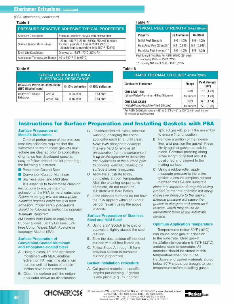
40US Headquarters TEL +(1) 781-935-4850 FAX +(1) 781-933-4318 • www.chomerics.com
Europe TEL +(44) 1628 404000 FAX +(44) 1628 404090Asia Pacific TEL +(852) 2 428 8008 FAX +(852) 2 423 8253
South America TEL +(55) 11 3917 1099 FAX +(55) 11 3917 0817
Surface Preparation ofMetallic Substrates
Optimal performance of the pressure-sensitive adhesive requires that thesubstrates to which these gaskets mustadhere are cleaned prior to application.Chomerics has developed specific,easy-to-follow procedures for preparingthe following substrates: Phosphate-Coated Steel Conversion-Coated Aluminum Stainless Steel and Mild Steel
It is essential to follow these cleaninginstructions to ensure maximumadhesion of the PSA to metal substrates.Failure to comply with the appropriatecleaning process could result in pooradhesion. Proper safety precautionsshould be followed to protect the operator.Materials Required:3M Scotch Brite Pads or equivalent,Rubber Gloves, Safety Glasses, Lint-Free Cotton Wipes; MEK, Acetone orIsopropyl Alcohol (IPA).
Surface Preparation ofConversion-Coated Aluminumand Phosphate-Coated SteelA. Using a clean, lint-free applicator,
moistened with MEK, acetonesolvent or IPA, wash the aluminumsurface until all traces of contam-ination have been removed.
B. Clean the surface until the cottonapplicator shows no discoloration.
C. If discoloration still exists, continuewashing, changing the cottonapplicator each time, until clean.Note: With phosphate coatings,it is very hard to remove alldiscoloration from the surface so itis up to the operator to determinethe cleanliness of the surface priorto bonding. Typically, cleaning thesurface 3 times is required.
D. Allow the substrate to drycompletely at room temperature.After the cleaning sequence iscomplete, do not touch thesubstrate with bare hands.
E. If the cleaned surfaces do not havethe PSA applied within an 8-hourperiod, rewash using the aboveprocess.
Surface Preparation of StainlessSteel and Mild Steel
A. Using a 3M Scotch Brite pad orequivalent, lightly abrade the steelsurface.
B. Blow the dust residue off the steelsurface with oil-free filtered air.
C. Follow Steps A through E fromprevious section to completesurface preparation.
Gasket Installation Procedure
A. Cut gasket material to specificlengths per drawing. If gasket is one piece (e.g., four corner
spliced gasket), pre-fit the assemblyto ensure fit and location.
B. Remove a portion of the releaseliner and position the gasket. Pressfirmly against gasket to tack inplace. Continue pressing alongentire length of gasket until it ispositioned and aligned to themating surface.
C. Using a rubber roller, apply moderate pressure to the entiregasket to ensure complete contactbetween the PSA and substrate.
Note: It is important during this rollingprocedure that the operator not applyexcessive pressure to the gasket.Extreme pressure will cause thegasket to elongate and creep as itrelaxes, which may cause anintermittent bond to the substratesurface.
Optimum Application Temperature
Temperatures below 50°F (10°C)can cause poor gasket adhesion to the substrate. Ideal gasketinstallation temperature is 72°F (22°C),ambient room temperature. Allmaterials should be stored at thistemperature when not in use.Hardware and gasket materials storedbelow 50°F should be brought to roomtemperature before installing gasket.
TYPICAL PEEL STRENGTH lb/inch (N/mm)
Property On Aluminum On Steel
Initial Peel Strength 6.0 (1.05) 6.0 (1.05)
Heat Aged Peel Strength* 5.4 (0.945) 5.4 (0.945)
Humidity Peel Strength** 6.0 (1.05) 6.0 (1.05)
Peel Strength Test Data Per ASTM D1000 (90° peel).* Heat aging 168 hrs / 158°F (70°C).
** Humidity 168 hrs /95% RH/ 158°F (70°C).
TYPICAL THROUGH FLANGEELECTRICAL RESISTANCE
Chomerics P/N 10-05-3369-S6304 @ 10% deflection @ 25% deflection(Ni/C filled silicone)
Hollow “D” Shape w/PSA 0.23 ohm 0.14 ohmExtrusion w/out PSA 0.16 ohm 0.14 ohm
RAPID THERMAL CYCLING* lb/inch (N/mm)
Conductive Elastomer Flange Peel Strength(90°)
CHO-SEAL 1485 Steel 7.0 (1.23)(Silver-Plated-Aluminum-Filled Silicone) Aluminum 7.0 (1.23)
CHO-SEAL S6304 Steel 6.5 (1.14)(Nickel-Plated-Graphite-Filled Silicone) Aluminum 5.5 (0.96)
*Per ASTM D1000; 5 cycles at –48° to 212°F (–40° to 100°C) with dwell time of15 minutes at each extreme.
Table 4
Table 5 Table 6
PRESSURE-SENSITIVE ADHESIVE TYPICAL PROPERTIES
Adhesive Description Pressure-sensitive acrylic with release liner
–20 to +150°F (–29 to +66°C); PSA will functionService Temperature Range for short periods of time @ 200°F (93°C);
ultimate high temperature limit 250°F (121°C)
Shelf Life Conditions One year at 158°F (70°C)/50% RH
Application Temperature Range 40 to 150°F (4 to 66°C)
Table 3
Elastomer Extrusions continued
(PSA Attachment, continued)
Instructions for Surface Preparation and Installing Gaskets with PSA
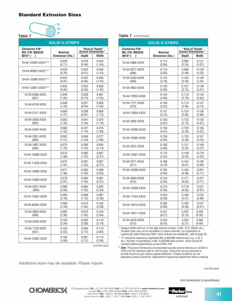
US Headquarters TEL +(1) 781-935-4850 FAX +(1) 781-933-4318 • www.chomerics.comEurope TEL +(44) 1628 404000 FAX +(44) 1628 404090
Asia Pacific TEL +(852) 2 428 8008 FAX +(852) 2 423 8253South America TEL +(55) 11 3917 1099 FAX +(55) 11 3917 0817
41continued
(mm dimensions in parentheses)
SOLID O-STRIPS
Chomerics P/N* “Rule of Thumb” MIL P/N: M83528 Nominal Groove Dimensions††
001X†-( ) Dimension [Dia.] Depth Width
10-04-2866-XXXX 0.112 0.092 0.121(2.84) (2.34) (3.07)
10-04-3077-XXXX 0.119 0.098 0.128(008) (3.02) (2.49) (3.25)
10-04-2463-XXXX 0.125 0.102 0.135(009) (3.18) (2.59) (3.43)
10-04-2862-XXXX 0.130 0.107 0.138(3.30) (2.72) (3.51)
19-04-12903-XXXX 0.134 0.110 0.143(3.40) (2.79) (3.63)
10-04-1721-XXXX 0.139 0.114 0.147(010) (3.53) (2.90) (3.73)
19-04-12904-XXXX 0.147 0.120 0.156(3.73) (3.05) (3.96)
10-04-3982-XXXX 0.150 0.123 0.158(3.81) (3.12) (4.01)
19-04-12906-XXXX 0.158 0.129 0.166(4.01) (3.28) (4.22)
19-04-12905-XXXX 0.159 0.130 0.167(4.04) (3.30) (4.24)
10-04-3231-XXXX 0.160 0.131 0.168(4.06) (3.33) (4.27)
19-04-12907-XXXX 0.170 0.139 0.178(4.32) (3.53) (4.52)
19-04-F371-XXXX 0.188 0.154 0.195(011) (4.78) (3.91) (4.95)
19-04-12908-XXXX 0.195 0.160 0.201(4.95) (4.06) (5.11)
10-04-2864-XXXX 0.216 0.177 0.227(012) (5.49) (4.50) (5.77)
19-04-12909-XXXX 0.219 0.179 0.231(5.56) (4.55) (5.87)
19-04-11453-XXXX 0.220 0.180 0.232(5.59) (4.57) (5.89)
19-04-12910-XXXX 0.236 0.193 0.247(5.99) (4.90) (6.27)
19-04-12911-XXXX 0.247 0.202 0.258(6.27) (5.13) (6.55)
10-04-3076-XXXX 0.250 0.205 0.260(013) (6.35) (5.21) (6.60)
SOLID O-STRIPS
Table 7
* Replace XXXX with four or five digit material number (1356, 1273, S6305, etc.).Smallest sizes may not be extrudable in certain materials. For explanation ofsuperscript codes following XXXX, which indicate non-availability, refer to page 38.
† “X” should be replaced by applicable MIL-G-83528B material type (e.g., A, B, C,etc.). Number in parentheses is MIL-G-83528B dash number, which should beinserted (without parentheses) at end of MIL P/N.
†† Note: The groove dimensions recommended assume groove tolerance of ±0.002 in.(0.05 mm) for standard solid O- and D-strips. Closure for ces are assumed toprovide maximum and uniform gasket deflection. If these conditions are notattainable,contact Chomerics’ Applications Engineering Department before ordering.
Dia.
continued
continued
Standard Extrusion Sizes
Additional sizes may be available. Please inquire.
Chomerics P/N* “Rule of Thumb” MIL P/N: M83528 Nominal Groove Dimensions††
001X†-( ) Dimension [Dia.] Depth Width
19-04-12895-XXXX2,3,4 0.028 0.018 0.055(0.71) (0.46) (1.40)
19-04-W993-XXXX2,3,4 0.030 0.020 0.056(0.76) (0.51) (1.42)
19-04-12896-XXXX2,3,4 0.032 0.022 0.056(0.81) (0.56) (1.42)
19-04-12897-XXXX2,3,4 0.033 0.023 0.056(0.84) (0.58) (1.42)
10-04-6386-XXXX 0.040 0.029 0.061(001) (1.02) (0.74) (1.55)
10-04-9139-XXXX 0.048 0.037 0.065(1.22) (0.94) (1.65)
10-04-C317-XXXX 0.050 0.038 0.068(1.27) (0.97) (1.73)
10-04-3560-XXXX 0.053 0.041 0.070(002) (1.35) (1.04) (1.78)
19-04-X294-XXXX 0.060 0.047 0.076(1.52) (1.19) (1.93)
10-04-2561-XXXX 0.062 0.049 0.077(003) (1.57) (1.24) (1.96)
10-04-1687-XXXX 0.070 0.056 0.084(004) (1.78) (1.42) (2.13)
19-04-12898-XXXX 0.074 0.060 0.087(1.88) (1.52) (2.21)
19-04-11228-XXXX 0.075 0.061 0.087(1.91) (1.55) (2.21)
19-04-12899-XXXX 0.077 0.063 0.089(1.96) (1.60) (2.26)
19-04-12900-XXXX 0.079 0.064 0.091(2.01) (1.63) (2.31)
10-04-2657-XXXX 0.080 0.065 0.092(005) (2.03) (1.65) (2.34)
19-04-12901-XXXX 0.085 0.069 0.097(2.16) (1.75) (2.46)
19-04-M394-XXXX 0.090 0.073 0.102(2.29) (1.85) (2.59)
10-04-2865-XXXX 0.093 0.076 0.104(006) (2.36) (1.93) (2.64)
10-04-3509-XXXX 0.100 0.082 0.110(2.54) (2.08) (2.79)
10-04-1720-XXXX 0.103 0.084 0.114(007) (2.62) (2.13) (2.90)
19-04-12902-XXXX 0.106 0.087 0.114(2.69) (2.21) (2.90)
Table 7 continued
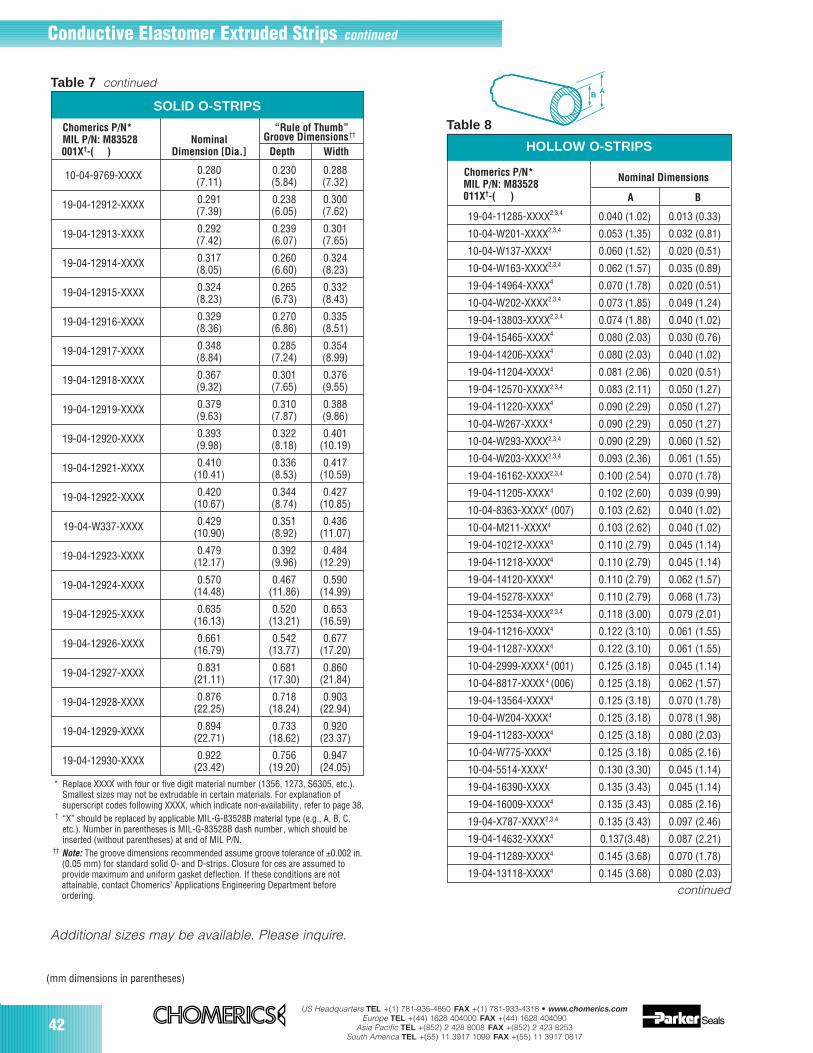
42US Headquarters TEL +(1) 781-935-4850 FAX +(1) 781-933-4318 • www.chomerics.com
Europe TEL +(44) 1628 404000 FAX +(44) 1628 404090Asia Pacific TEL +(852) 2 428 8008 FAX +(852) 2 423 8253
South America TEL +(55) 11 3917 1099 FAX +(55) 11 3917 0817
Conductive Elastomer Extruded Strips continued
HOLLOW O-STRIPS
19-04-11285-XXXX2,3,4 0.040 (1.02) 0.013 (0.33)
10-04-W201-XXXX2,3,4 0.053 (1.35) 0.032 (0.81)
10-04-W137-XXXX4 0.060 (1.52) 0.020 (0.51)
10-04-W163-XXXX2,3,4 0.062 (1.57) 0.035 (0.89)
19-04-14964-XXXX4 0.070 (1.78) 0.020 (0.51)
10-04-W202-XXXX2,3,4 0.073 (1.85) 0.049 (1.24)
19-04-13803-XXXX2,3,4 0.074 (1.88) 0.040 (1.02)
19-04-15465-XXXX4 0.080 (2.03) 0.030 (0.76)
19-04-14206-XXXX4 0.080 (2.03) 0.040 (1.02)
19-04-11204-XXXX4 0.081 (2.06) 0.020 (0.51)
19-04-12570-XXXX2,3,4 0.083 (2.11) 0.050 (1.27)
19-04-11220-XXXX4 0.090 (2.29) 0.050 (1.27)
10-04-W267-XXXX4 0.090 (2.29) 0.050 (1.27)
10-04-W293-XXXX2,3,4 0.090 (2.29) 0.060 (1.52)
10-04-W203-XXXX2,3,4 0.093 (2.36) 0.061 (1.55)
19-04-16162-XXXX2,3,4 0.100 (2.54) 0.070 (1.78)
19-04-11205-XXXX4 0.102 (2.60) 0.039 (0.99)
10-04-8363-XXXX4 (007) 0.103 (2.62) 0.040 (1.02)
10-04-M211-XXXX4 0.103 (2.62) 0.040 (1.02)
19-04-10212-XXXX4 0.110 (2.79) 0.045 (1.14)
19-04-11218-XXXX4 0.110 (2.79) 0.045 (1.14)
19-04-14120-XXXX4 0.110 (2.79) 0.062 (1.57)
19-04-15278-XXXX4 0.110 (2.79) 0.068 (1.73)
19-04-12534-XXXX2,3,4 0.118 (3.00) 0.079 (2.01)
19-04-11216-XXXX4 0.122 (3.10) 0.061 (1.55)
19-04-11287-XXXX4 0.122 (3.10) 0.061 (1.55)
10-04-2999-XXXX4 (001) 0.125 (3.18) 0.045 (1.14)
10-04-8817-XXXX4 (006) 0.125 (3.18) 0.062 (1.57)
19-04-13564-XXXX4 0.125 (3.18) 0.070 (1.78)
10-04-W204-XXXX4 0.125 (3.18) 0.078 (1.98)
19-04-11283-XXXX4 0.125 (3.18) 0.080 (2.03)
10-04-W775-XXXX4 0.125 (3.18) 0.085 (2.16)
10-04-5514-XXXX4 0.130 (3.30) 0.045 (1.14)
19-04-16390-XXXX 0.135 (3.43) 0.045 (1.14)
19-04-16009-XXXX4 0.135 (3.43) 0.085 (2.16)
19-04-X787-XXXX2,3,4 0.135 (3.43) 0.097 (2.46)
19-04-14632-XXXX4 0.137(3.48) 0.087 (2.21)
19-04-11289-XXXX4 0.145 (3.68) 0.070 (1.78)
19-04-13118-XXXX4 0.145 (3.68) 0.080 (2.03)
Table 8
B A
Chomerics P/N*MIL P/N: M83528
Nominal Dimensions
011X†-( ) A B
SOLID O-STRIPS
Table 7 continued
Chomerics P/N* “Rule of Thumb” MIL P/N: M83528 Nominal Groove Dimensions††
001X†-( ) Dimension [Dia.] Depth Width
10-04-9769-XXXX 0.280 0.230 0.288(7.11) (5.84) (7.32)
19-04-12912-XXXX 0.291 0.238 0.300(7.39) (6.05) (7.62)
19-04-12913-XXXX 0.292 0.239 0.301(7.42) (6.07) (7.65)
19-04-12914-XXXX 0.317 0.260 0.324(8.05) (6.60) (8.23)
19-04-12915-XXXX 0.324 0.265 0.332(8.23) (6.73) (8.43)
19-04-12916-XXXX 0.329 0.270 0.335(8.36) (6.86) (8.51)
19-04-12917-XXXX 0.348 0.285 0.354(8.84) (7.24) (8.99)
19-04-12918-XXXX 0.367 0.301 0.376(9.32) (7.65) (9.55)
19-04-12919-XXXX 0.379 0.310 0.388(9.63) (7.87) (9.86)
19-04-12920-XXXX 0.393 0.322 0.401(9.98) (8.18) (10.19)
19-04-12921-XXXX 0.410 0.336 0.417(10.41) (8.53) (10.59)
19-04-12922-XXXX 0.420 0.344 0.427(10.67) (8.74) (10.85)
19-04-W337-XXXX 0.429 0.351 0.436(10.90) (8.92) (11.07)
19-04-12923-XXXX 0.479 0.392 0.484(12.17) (9.96) (12.29)
19-04-12924-XXXX 0.570 0.467 0.590(14.48) (11.86) (14.99)
19-04-12925-XXXX 0.635 0.520 0.653(16.13) (13.21) (16.59)
19-04-12926-XXXX 0.661 0.542 0.677(16.79) (13.77) (17.20)
19-04-12927-XXXX 0.831 0.681 0.860(21.11) (17.30) (21.84)
19-04-12928-XXXX 0.876 0.718 0.903(22.25) (18.24) (22.94)
19-04-12929-XXXX 0.894 0.733 0.920(22.71) (18.62) (23.37)
19-04-12930-XXXX 0.922 0.756 0.947(23.42) (19.20) (24.05)
* Replace XXXX with four or five digit material number (1356, 1273, S6305, etc.).Smallest sizes may not be extrudable in certain materials. For explanation ofsuperscript codes following XXXX, which indicate non-availability, refer to page 38.
† “X” should be replaced by applicable MIL-G-83528B material type (e.g., A, B, C,etc.). Number in parentheses is MIL-G-83528B dash number, which should beinserted (without parentheses) at end of MIL P/N.
†† Note: The groove dimensions recommended assume groove tolerance of ±0.002 in.(0.05 mm) for standard solid O- and D-strips. Closure for ces are assumed toprovide maximum and uniform gasket deflection. If these conditions are notattainable, contact Chomerics’ Applications Engineering Department beforeordering.
(mm dimensions in parentheses)
Additional sizes may be available. Please inquire.
continued
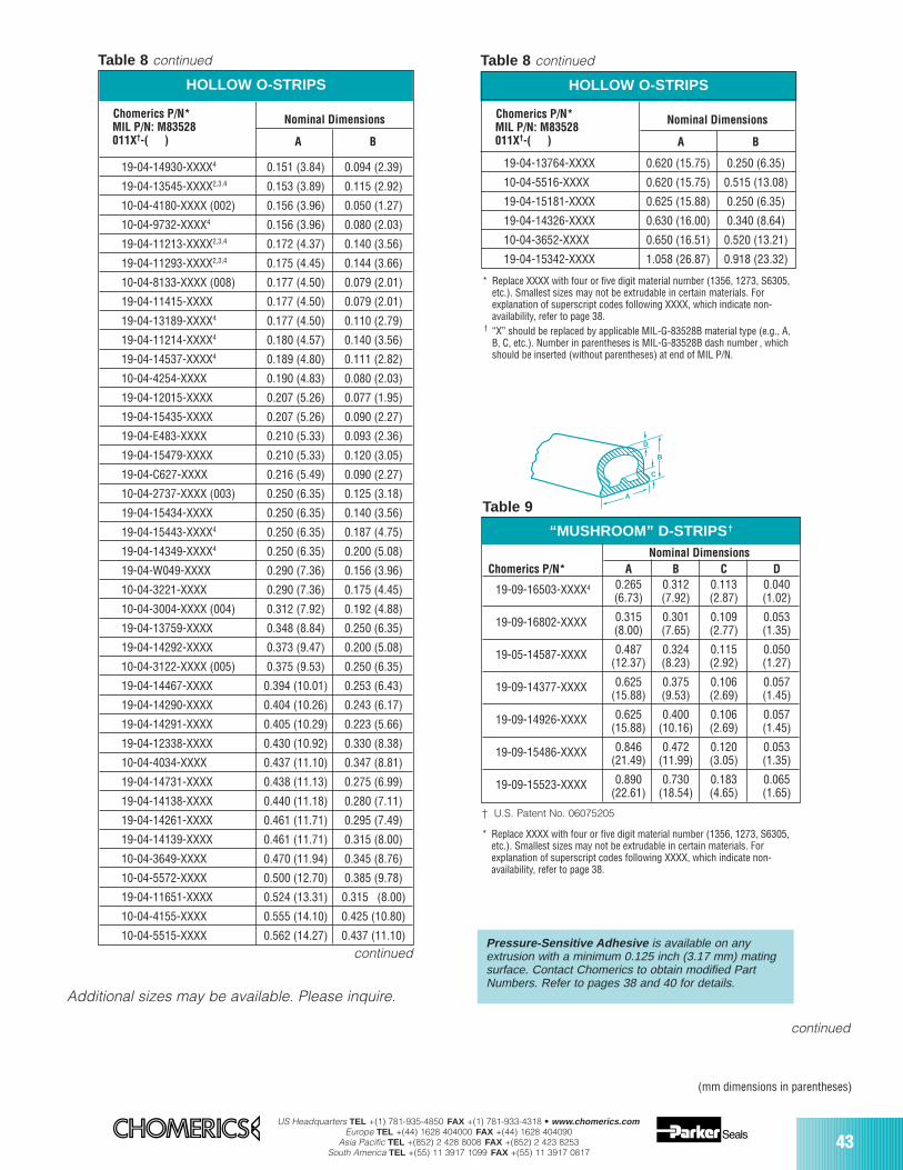
US Headquarters TEL +(1) 781-935-4850 FAX +(1) 781-933-4318 • www.chomerics.comEurope TEL +(44) 1628 404000 FAX +(44) 1628 404090
Asia Pacific TEL +(852) 2 428 8008 FAX +(852) 2 423 8253South America TEL +(55) 11 3917 1099 FAX +(55) 11 3917 0817
43
“MUSHROOM” D-STRIPS †
(mm dimensions in parentheses)
HOLLOW O-STRIPS
19-04-14930-XXXX4 0.151 (3.84) 0.094 (2.39)
19-04-13545-XXXX2,3,4 0.153 (3.89) 0.115 (2.92)
10-04-4180-XXXX (002) 0.156 (3.96) 0.050 (1.27)
10-04-9732-XXXX4 0.156 (3.96) 0.080 (2.03)
19-04-11213-XXXX2,3,4 0.172 (4.37) 0.140 (3.56)
19-04-11293-XXXX2,3,4 0.175 (4.45) 0.144 (3.66)
10-04-8133-XXXX (008) 0.177 (4.50) 0.079 (2.01)
19-04-11415-XXXX 0.177 (4.50) 0.079 (2.01)
19-04-13189-XXXX4 0.177 (4.50) 0.110 (2.79)
19-04-11214-XXXX4 0.180 (4.57) 0.140 (3.56)
19-04-14537-XXXX4 0.189 (4.80) 0.111 (2.82)
10-04-4254-XXXX 0.190 (4.83) 0.080 (2.03)
19-04-12015-XXXX 0.207 (5.26) 0.077 (1.95)
19-04-15435-XXXX 0.207 (5.26) 0.090 (2.27)
19-04-E483-XXXX 0.210 (5.33) 0.093 (2.36)
19-04-15479-XXXX 0.210 (5.33) 0.120 (3.05)
19-04-C627-XXXX 0.216 (5.49) 0.090 (2.27)
10-04-2737-XXXX (003) 0.250 (6.35) 0.125 (3.18)
19-04-15434-XXXX 0.250 (6.35) 0.140 (3.56)
19-04-15443-XXXX4 0.250 (6.35) 0.187 (4.75)
19-04-14349-XXXX4 0.250 (6.35) 0.200 (5.08)
19-04-W049-XXXX 0.290 (7.36) 0.156 (3.96)
10-04-3221-XXXX 0.290 (7.36) 0.175 (4.45)
10-04-3004-XXXX (004) 0.312 (7.92) 0.192 (4.88)
19-04-13759-XXXX 0.348 (8.84) 0.250 (6.35)
19-04-14292-XXXX 0.373 (9.47) 0.200 (5.08)
10-04-3122-XXXX (005) 0.375 (9.53) 0.250 (6.35)
19-04-14467-XXXX 0.394 (10.01) 0.253 (6.43)
19-04-14290-XXXX 0.404 (10.26) 0.243 (6.17)
19-04-14291-XXXX 0.405 (10.29) 0.223 (5.66)
19-04-12338-XXXX 0.430 (10.92) 0.330 (8.38)
10-04-4034-XXXX 0.437 (11.10) 0.347 (8.81)
19-04-14731-XXXX 0.438 (11.13) 0.275 (6.99)
19-04-14138-XXXX 0.440 (11.18) 0.280 (7.11)
19-04-14261-XXXX 0.461 (11.71) 0.295 (7.49)
19-04-14139-XXXX 0.461 (11.71) 0.315 (8.00)
10-04-3649-XXXX 0.470 (11.94) 0.345 (8.76)
10-04-5572-XXXX 0.500 (12.70) 0.385 (9.78)
19-04-11651-XXXX 0.524 (13.31) 0.315 (8.00)
10-04-4155-XXXX 0.555 (14.10) 0.425 (10.80)
10-04-5515-XXXX 0.562 (14.27) 0.437 (11.10)
Table 8 continued
* Replace XXXX with four or five digit material number (1356, 1273, S6305,etc.). Smallest sizes may not be extrudable in certain materials. Forexplanation of superscript codes following XXXX, which indicate non-availability, refer to page 38.
continued
Pressure-Sensitive Adhesive is available on anyextrusion with a minimum 0.125 inch (3.17 mm) matingsurface. Contact Chomerics to obtain modified PartNumbers. Refer to pages 38 and 40 for details.
Chomerics P/N*MIL P/N: M83528
Nominal Dimensions
011X†-( ) A B
Nominal DimensionsChomerics P/N* A B C D
19-09-16503-XXXX4 0.265 0.312 0.113 0.040(6.73) (7.92) (2.87) (1.02)
19-09-16802-XXXX 0.315 0.301 0.109 0.053(8.00) (7.65) (2.77) (1.35)
19-05-14587-XXXX 0.487 0.324 0.115 0.050(12.37) (8.23) (2.92) (1.27)
19-09-14377-XXXX 0.625 0.375 0.106 0.057(15.88) (9.53) (2.69) (1.45)
19-09-14926-XXXX 0.625 0.400 0.106 0.057(15.88) (10.16) (2.69) (1.45)
19-09-15486-XXXX 0.846 0.472 0.120 0.053(21.49) (11.99) (3.05) (1.35)
19-09-15523-XXXX 0.890 0.730 0.183 0.065(22.61) (18.54) (4.65) (1.65)
B
C
D
A
Table 9
† U.S. Patent No. 06075205
Additional sizes may be available. Please inquire.
HOLLOW O-STRIPS
19-04-13764-XXXX 0.620 (15.75) 0.250 (6.35)
10-04-5516-XXXX 0.620 (15.75) 0.515 (13.08)
19-04-15181-XXXX 0.625 (15.88) 0.250 (6.35)
19-04-14326-XXXX 0.630 (16.00) 0.340 (8.64)
10-04-3652-XXXX 0.650 (16.51) 0.520 (13.21)
19-04-15342-XXXX 1.058 (26.87) 0.918 (23.32)
Chomerics P/N*MIL P/N: M83528
Nominal Dimensions
011X†-( ) A B
Table 8 continued
* Replace XXXX with four or five digit material number (1356, 1273, S6305,etc.). Smallest sizes may not be extrudable in certain materials. Forexplanation of superscript codes following XXXX, which indicate non-availability, refer to page 38.
† “X” should be replaced by applicable MIL-G-83528B material type (e.g., A,B, C, etc.). Number in parentheses is MIL-G-83528B dash number , whichshould be inserted (without parentheses) at end of MIL P/N.
continued
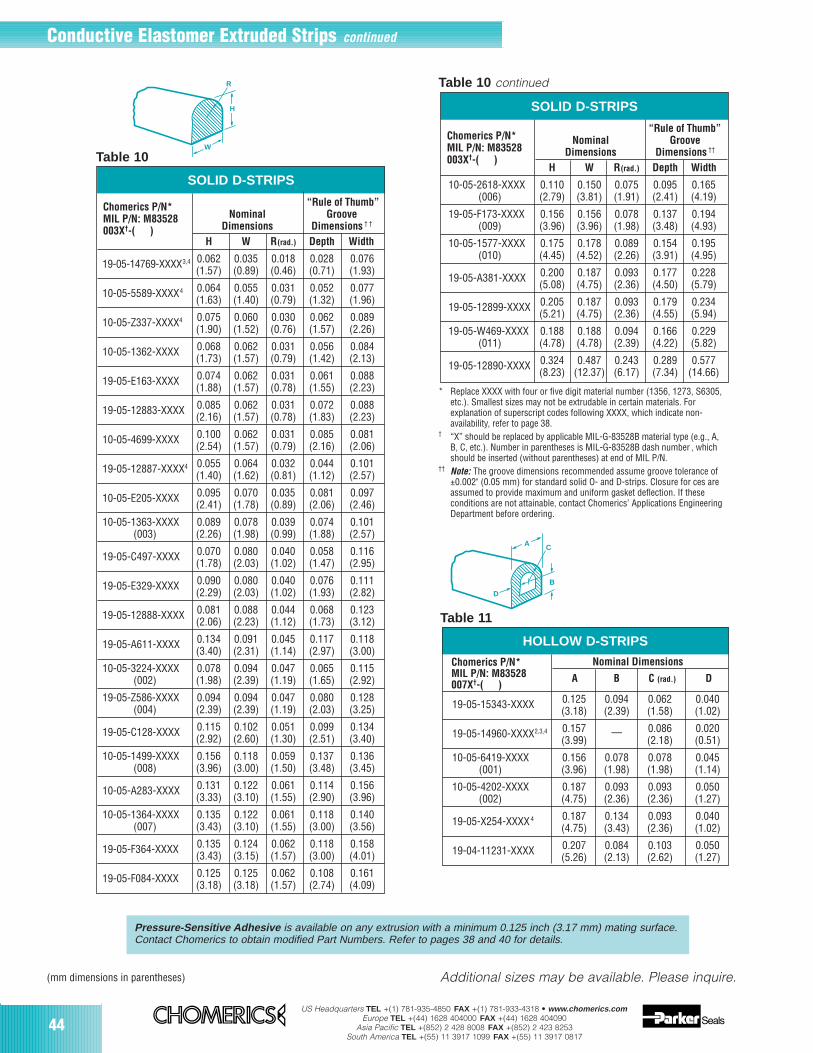
44US Headquarters TEL +(1) 781-935-4850 FAX +(1) 781-933-4318 • www.chomerics.com
Europe TEL +(44) 1628 404000 FAX +(44) 1628 404090Asia Pacific TEL +(852) 2 428 8008 FAX +(852) 2 423 8253
South America TEL +(55) 11 3917 1099 FAX +(55) 11 3917 0817
H
W
R
HOLLOW D-STRIPS
Nominal Dimensions
19-05-15343-XXXX 0.125 0.094 0.062 0.040(3.18) (2.39) (1.58) (1.02)
19-05-14960-XXXX2,3,4 0.157 — 0.086 0.020(3.99) (2.18) (0.51)
10-05-6419-XXXX 0.156 0.078 0.078 0.045(001) (3.96) (1.98) (1.98) (1.14)
10-05-4202-XXXX 0.187 0.093 0.093 0.050(002) (4.75) (2.36) (2.36) (1.27)
19-05-X254-XXXX4 0.187 0.134 0.093 0.040(4.75) (3.43) (2.36) (1.02)
19-04-11231-XXXX 0.207 0.084 0.103 0.050(5.26) (2.13) (2.62) (1.27)
SOLID D-STRIPS
(mm dimensions in parentheses)
A
C
B
D
Table 11
Pressure-Sensitive Adhesive is available on any extrusion with a minimum 0.125 inch (3.17 mm) mating surface.Contact Chomerics to obtain modified Part Numbers. Refer to pages 38 and 40 for details.
“Rule of Thumb”Nominal Groove
Dimensions Dimensions ††
H W R(rad.) Depth Width
10-05-2618-XXXX 0.110 0.150 0.075 0.095 0.165(006) (2.79) (3.81) (1.91) (2.41) (4.19)
19-05-F173-XXXX 0.156 0.156 0.078 0.137 0.194(009) (3.96) (3.96) (1.98) (3.48) (4.93)
10-05-1577-XXXX 0.175 0.178 0.089 0.154 0.195(010) (4.45) (4.52) (2.26) (3.91) (4.95)
19-05-A381-XXXX 0.200 0.187 0.093 0.177 0.228(5.08) (4.75) (2.36) (4.50) (5.79)
19-05-12899-XXXX 0.205 0.187 0.093 0.179 0.234(5.21) (4.75) (2.36) (4.55) (5.94)
19-05-W469-XXXX 0.188 0.188 0.094 0.166 0.229(011) (4.78) (4.78) (2.39) (4.22) (5.82)
19-05-12890-XXXX 0.324 0.487 0.243 0.289 0.577(8.23) (12.37) (6.17) (7.34) (14.66)
Table 10 continued
SOLID D-STRIPS
“Rule of Thumb”Nominal Groove
Dimensions Dimensions † †
H W R(rad.) Depth Width
19-05-14769-XXXX3,4 0.062 0.035 0.018 0.028 0.076(1.57) (0.89) (0.46) (0.71) (1.93)
10-05-5589-XXXX4 0.064 0.055 0.031 0.052 0.077(1.63) (1.40) (0.79) (1.32) (1.96)
10-05-Z337-XXXX4 0.075 0.060 0.030 0.062 0.089(1.90) (1.52) (0.76) (1.57) (2.26)
10-05-1362-XXXX 0.068 0.062 0.031 0.056 0.084(1.73) (1.57) (0.79) (1.42) (2.13)
19-05-E163-XXXX 0.074 0.062 0.031 0.061 0.088(1.88) (1.57) (0.78) (1.55) (2.23)
19-05-12883-XXXX 0.085 0.062 0.031 0.072 0.088(2.16) (1.57) (0.78) (1.83) (2.23)
10-05-4699-XXXX 0.100 0.062 0.031 0.085 0.081(2.54) (1.57) (0.79) (2.16) (2.06)
19-05-12887-XXXX4 0.055 0.064 0.032 0.044 0.101(1.40) (1.62) (0.81) (1.12) (2.57)
10-05-E205-XXXX 0.095 0.070 0.035 0.081 0.097(2.41) (1.78) (0.89) (2.06) (2.46)
10-05-1363-XXXX 0.089 0.078 0.039 0.074 0.101(003) (2.26) (1.98) (0.99) (1.88) (2.57)
19-05-C497-XXXX 0.070 0.080 0.040 0.058 0.116(1.78) (2.03) (1.02) (1.47) (2.95)
19-05-E329-XXXX 0.090 0.080 0.040 0.076 0.111(2.29) (2.03) (1.02) (1.93) (2.82)
19-05-12888-XXXX 0.081 0.088 0.044 0.068 0.123(2.06) (2.23) (1.12) (1.73) (3.12)
19-05-A611-XXXX 0.134 0.091 0.045 0.117 0.118(3.40) (2.31) (1.14) (2.97) (3.00)
10-05-3224-XXXX 0.078 0.094 0.047 0.065 0.115(002) (1.98) (2.39) (1.19) (1.65) (2.92)
19-05-Z586-XXXX 0.094 0.094 0.047 0.080 0.128(004) (2.39) (2.39) (1.19) (2.03) (3.25)
19-05-C128-XXXX 0.115 0.102 0.051 0.099 0.134(2.92) (2.60) (1.30) (2.51) (3.40)
10-05-1499-XXXX 0.156 0.118 0.059 0.137 0.136(008) (3.96) (3.00) (1.50) (3.48) (3.45)
10-05-A283-XXXX 0.131 0.122 0.061 0.114 0.156(3.33) (3.10) (1.55) (2.90) (3.96)
10-05-1364-XXXX 0.135 0.122 0.061 0.118 0.140(007) (3.43) (3.10) (1.55) (3.00) (3.56)
19-05-F364-XXXX 0.135 0.124 0.062 0.118 0.158(3.43) (3.15) (1.57) (3.00) (4.01)
19-05-F084-XXXX 0.125 0.125 0.062 0.108 0.161(3.18) (3.18) (1.57) (2.74) (4.09)
Table 10
* Replace XXXX with four or five digit material number (1356, 1273, S6305,etc.). Smallest sizes may not be extrudable in certain materials. Forexplanation of superscript codes following XXXX, which indicate non-availability, refer to page 38.
† “X” should be replaced by applicable MIL-G-83528B material type (e.g., A,B, C, etc.). Number in parentheses is MIL-G-83528B dash number , whichshould be inserted (without parentheses) at end of MIL P/N.
†† Note: The groove dimensions recommended assume groove tolerance of±0.002" (0.05 mm) for standard solid O- and D-strips. Closure for ces areassumed to provide maximum and uniform gasket deflection. If theseconditions are not attainable, contact Chomerics’ Applications EngineeringDepartment before ordering.
Chomerics P/N*MIL P/N: M83528003X†-( )
Additional sizes may be available. Please inquire.
Chomerics P/N*MIL P/N: M83528003X†-( )
A B C (rad.) D
Chomerics P/N*MIL P/N: M83528007X†-( )
Conductive Elastomer Extruded Strips continued
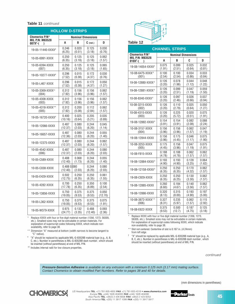
US Headquarters TEL +(1) 781-935-4850 FAX +(1) 781-933-4318 • www.chomerics.comEurope TEL +(44) 1628 404000 FAX +(44) 1628 404090
Asia Pacific TEL +(852) 2 428 8008 FAX +(852) 2 423 8253South America TEL +(55) 11 3917 1099 FAX +(55) 11 3917 0817
45
CHANNEL STRIPS
HOLLOW D-STRIPS
(mm dimensions in parentheses)
continued
* Replace XXXX with four or five digit material number (1356, 1273, S6305,etc.). Smallest sizes may not be extrudable in certain materials. Forexplanation of superscript codes following XXXX, which indicate non-availability, refer to page 38.
** Dimension “A” measured at bottom (width narrows to become tangent to“C” radius).
† “X” should be replaced by applicable MIL-G-83528B material type (e.g., A, B,C, etc.). Number in parentheses is MIL-G-83528B dash number , which shouldbe inserted (without parentheses) at end of MIL P/N.
†† Includes internal radii for low closure properties.
19-08-14054-XXXX4 0.075 0.099 0.025 0.032(1.91) (2.51) (0.64) (0.81)
10-08-6475-XXXX4 0.100 0.100 0.034 0.033(001) (2.54) (2.54) (0.86) (0.84)
19-08-12880-XXXX4 0.126 0.078 0.044 0.048(3.20) (1.98) (1.12) (1.22)
19-08-12881-XXXX4 0.126 0.099 0.047 0.059(3.20) (2.51) (1.19) (1.50)
10-08-8340-XXXX4 0.126 0.097 0.026 0.037(3.20) (2.46) (0.66) (0.94)
10-08-3215-XXXX 0.126 0.110 0.025 0.050(002) (3.20) (2.79) (0.64) (1.27)
10-08-4315-XXXX 0.126 0.225 0.020 0.075(003) (3.20) (5.72) (0.51) (1.91)
19-08-12882-XXXX4 0.154 0.154 0.082 0.088(3.91) (3.91) (2.08) (2.24)
10-08-3157-XXXX 0.156 0.156 0.062 0.047(004) (3.96) (3.96) (1.57) (1.19)
19-08-12844-XXXX 0.156 0.175 0.046 0.075(3.96) (4.45) (1.17) (1.90)
10-08-3253-XXXX 0.175 0.156 0.047 0.075(005) (4.45) (3.96) (1.19) (1.91)
10-08-F815-XXXX 0.188 0.188 0.062 0.062(4.78) (4.78) (1.57) (1.57)
19-08-12884-XXXX4 0.193 0.193 0.128 0.064(4.90) (4.90) (3.25) (1.62)
19-08-12158-XXXX4 0.250 0.250 0.170 0.062(6.35) (6.35) (4.32) (1.57)
19-08-C929-XXXX 0.250 0.250 0.130 0.062(6.35) (6.25) (3.30) (1.57)
19-08-12885-XXXX 0.260 0.184 0.140 0.062(6.60) (4.67) (3.56) (1.57)
19-08-12886-XXXX 0.320 0.315 0.193 0.197(8.13) (8.00) (4.90) (5.00)
10-08-3872-XXXX** 0.327 0.235 0.062 0.115(006) (8.31) (5.97) (1.57) (2.92)
19-08-E622-XXXX0.375 0.500 0.187 0.125(9.53) (12.7) (4.75) (3.18)
Table 12
* Replace XXXX with four or five digit material number (1356, 1273,S6305, etc.). Smallest sizes may not be extrudable in certain materials.For explanation of superscript codes following XXXX, which indicate non-availability, refer to page 38.
** Slot not centered. Centerline of slot is 0.167 in. (4.24mm)from left edge.
† “X” should be replaced by applicable MIL-G-83528B material type (e.g., A,B, C, etc.). Number in parentheses is MIL-G-83528B dash number , whichshould be inserted (without parentheses) at end of MIL P/N.
A
B
C
D
19-05-11440-XXXX4 0.246 0.020 0.125 0.030(6.25) (0.51) (3.18) (0.76)
10-05-6991-XXXX 0.250 0.125 0.125 0.062(6.35) (3.18) (3.18) (1.57)
10-05-6394-XXXX 0.250 0.125 0.125 0.065(007) (6.35) (3.18) (3.18) (1.65)
19-05-10277-XXXX4 0.296 0.015 0.172 0.030(7.52) (0.38) (4.37) (0.76)
19-05-L467-XXXX 0.296 0.015 0.172 0.050(7.52) (0.38) (4.37) (1.27)
10-05-3369-XXXX†† 0.312 0.156 0.156 0.062(004) (7.92) (3.96) (3.96) (1.57)
10-05-4308-XXXX 0.312 0.156 0.156 0.062(003) (7.92) (3.96) (3.96) (1.57)
10-05-4318-XXXX** 0.312 0.200 0.112 0.062(005) (7.92) (5.08) (2.84) (1.57)
19-05-16720-XXXX4 0.400 0.025 0.205 0.035(10.16) (0.64) (5.21) (0.89)
19-05-12066-XXXX 0.487 0.080 0.244 0.045(12.37) (2.03) (6.20) (1.14)
19-05-16657-XXXX 0.487 0.080 0.244 0.055(12.36) (2.03) (6.20) (1.40)
19-05-12375-XXXX 0.487 0.080 0.244 0.062(12.37) (2.03) (6.20) (1.57)
10-05-4542-XXXX 0.487 0.080 0.244 0.080(006) (12.37) (2.03) (6.20) (2.03)
10-05-C589-XXXX 0.488 0.068 0.244 0.055(12.40) (1.73) (6.20) (1.40)
10-05-C038-XXXX 0.488 0.080 0.244 0.080(12.40) (2.03) (6.20) (2.03)
19-05-E429-XXXX 0.502 0.250 0.250 0.061(12.75) (6.35) (6.35) (1.55)
10-05-4282-XXXX 0.700 0.250 0.350 0.100(17.78) (6.35) (8.89) (2.54)
19-05-13856-XXXX 0.750 0.375 0.375 0.050(19.05) (9.53) (9.53) (12.70)
19-05-L362-XXXX 0.750 0.375 0.375 0.075(19.05) (9.53) (9.53) (1.91)
19-05-W379-XXXX 0.975 0.132 0.488 0.093(24.77) (3.35) (12.40) (2.36)
Table 11 continued
Chomerics P/N*MIL P/N: M83528007X†-( )
Nominal Dimensions
A B C (rad.) D
Chomerics P/N*MIL P/N: M83528010X†-( ) A B C D
Nominal Dimensions
Pressure-Sensitive Adhesive is available on any extrusion with a minimum 0.125 inch (3.17 mm) mating surface.Contact Chomerics to obtain modified Part Numbers. Refer to pages 38 and 40 for details.
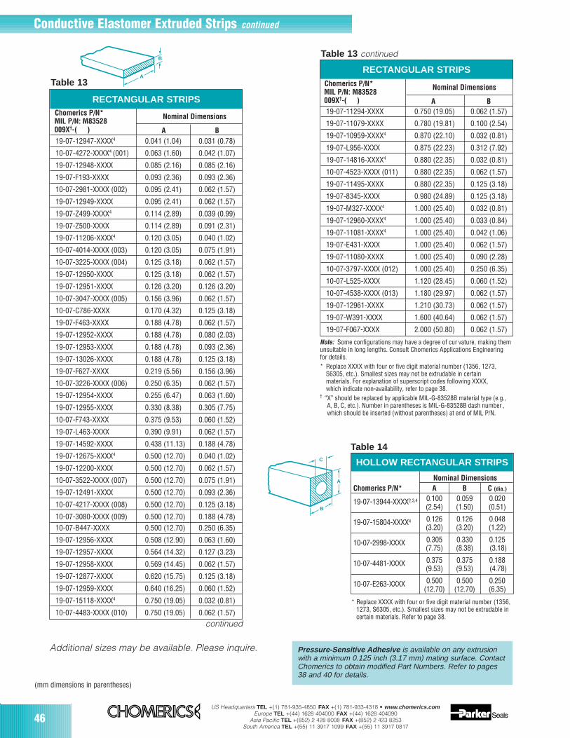
46US Headquarters TEL +(1) 781-935-4850 FAX +(1) 781-933-4318 • www.chomerics.com
Europe TEL +(44) 1628 404000 FAX +(44) 1628 404090Asia Pacific TEL +(852) 2 428 8008 FAX +(852) 2 423 8253
South America TEL +(55) 11 3917 1099 FAX +(55) 11 3917 0817
HOLLOW RECTANGULAR STRIPS
Nominal DimensionsChomerics P/N* A B C (dia.)
19-07-13944-XXXX2,3,4 0.100 0.059 0.020(2.54) (1.50) (0.51)
19-07-15804-XXXX4 0.126 0.126 0.048(3.20) (3.20) (1.22)
10-07-2998-XXXX 0.305 0.330 0.125(7.75) (8.38) (3.18)
10-07-4481-XXXX 0.375 0.375 0.188(9.53) (9.53) (4.78)
10-07-E263-XXXX 0.500 0.500 0.250(12.70) (12.70) (6.35)
(mm dimensions in parentheses)
Note: Some configurations may have a degree of cur vature, making themunsuitable in long lengths. Consult Chomerics Applications Engineeringfor details.* Replace XXXX with four or five digit material number (1356, 1273,
S6305, etc.). Smallest sizes may not be extrudable in certain materials. For explanation of superscript codes following XXXX, which indicate non-availability, refer to page 38.
† “X” should be replaced by applicable MIL-G-83528B material type (e.g., A, B, C, etc.). Number in parentheses is MIL-G-83528B dash number , which should be inserted (without parentheses) at end of MIL P/N.
Table 14
* Replace XXXX with four or five digit material number (1356,1273, S6305, etc.). Smallest sizes may not be extrudable incertain materials. Refer to page 38.
A
B
C
RECTANGULAR STRIPS
Table 13 continued
19-07-11294-XXXX 0.750 (19.05) 0.062 (1.57)
19-07-11079-XXXX 0.780 (19.81) 0.100 (2.54)
19-07-10959-XXXX4 0.870 (22.10) 0.032 (0.81)
19-07-L956-XXXX 0.875 (22.23) 0.312 (7.92)
19-07-14816-XXXX4 0.880 (22.35) 0.032 (0.81)
10-07-4523-XXXX (011) 0.880 (22.35) 0.062 (1.57)
19-07-11495-XXXX 0.880 (22.35) 0.125 (3.18)
19-07-8345-XXXX 0.980 (24.89) 0.125 (3.18)
19-07-M327-XXXX4 1.000 (25.40) 0.032 (0.81)
19-07-12960-XXXX4 1.000 (25.40) 0.033 (0.84)
19-07-11081-XXXX4 1.000 (25.40) 0.042 (1.06)
19-07-E431-XXXX 1.000 (25.40) 0.062 (1.57)
19-07-11080-XXXX 1.000 (25.40) 0.090 (2.28)
10-07-3797-XXXX (012) 1.000 (25.40) 0.250 (6.35)
10-07-L525-XXXX 1.120 (28.45) 0.060 (1.52)
10-07-4538-XXXX (013) 1.180 (29.97) 0.062 (1.57)
19-07-12961-XXXX 1.210 (30.73) 0.062 (1.57)
19-07-W391-XXXX 1.600 (40.64) 0.062 (1.57)
19-07-F067-XXXX 2.000 (50.80) 0.062 (1.57)
B
A
RECTANGULAR STRIPS
Table 13
Pressure-Sensitive Adhesive is available on any extrusionwith a minimum 0.125 inch (3.17 mm) mating surface. ContactChomerics to obtain modified Part Numbers. Refer to pages38 and 40 for details.
19-07-12947-XXXX4 0.041 (1.04) 0.031 (0.78)
10-07-4272-XXXX4 (001) 0.063 (1.60) 0.042 (1.07)
19-07-12948-XXXX 0.085 (2.16) 0.085 (2.16)
19-07-F193-XXXX 0.093 (2.36) 0.093 (2.36)
10-07-2981-XXXX (002) 0.095 (2.41) 0.062 (1.57)
19-07-12949-XXXX 0.095 (2.41) 0.062 (1.57)
19-07-Z499-XXXX4 0.114 (2.89) 0.039 (0.99)
19-07-Z500-XXXX 0.114 (2.89) 0.091 (2.31)
19-07-11206-XXXX4 0.120 (3.05) 0.040 (1.02)
10-07-4014-XXXX (003) 0.120 (3.05) 0.075 (1.91)
10-07-3225-XXXX (004) 0.125 (3.18) 0.062 (1.57)
19-07-12950-XXXX 0.125 (3.18) 0.062 (1.57)
19-07-12951-XXXX 0.126 (3.20) 0.126 (3.20)
10-07-3047-XXXX (005) 0.156 (3.96) 0.062 (1.57)
10-07-C786-XXXX 0.170 (4.32) 0.125 (3.18)
19-07-F463-XXXX 0.188 (4.78) 0.062 (1.57)
19-07-12952-XXXX 0.188 (4.78) 0.080 (2.03)
19-07-12953-XXXX 0.188 (4.78) 0.093 (2.36)
19-07-13026-XXXX 0.188 (4.78) 0.125 (3.18)
19-07-F627-XXXX 0.219 (5.56) 0.156 (3.96)
10-07-3226-XXXX (006) 0.250 (6.35) 0.062 (1.57)
19-07-12954-XXXX 0.255 (6.47) 0.063 (1.60)
19-07-12955-XXXX 0.330 (8.38) 0.305 (7.75)
10-07-F743-XXXX 0.375 (9.53) 0.060 (1.52)
19-07-L463-XXXX 0.390 (9.91) 0.062 (1.57)
19-07-14592-XXXX 0.438 (11.13) 0.188 (4.78)
19-07-12675-XXXX4 0.500 (12.70) 0.040 (1.02)
19-07-12200-XXXX 0.500 (12.70) 0.062 (1.57)
10-07-3522-XXXX (007) 0.500 (12.70) 0.075 (1.91)
19-07-12491-XXXX 0.500 (12.70) 0.093 (2.36)
10-07-4217-XXXX (008) 0.500 (12.70) 0.125 (3.18)
10-07-3080-XXXX (009) 0.500 (12.70) 0.188 (4.78)10-07-B447-XXXX 0.500 (12.70) 0.250 (6.35)
19-07-12956-XXXX 0.508 (12.90) 0.063 (1.60)
19-07-12957-XXXX 0.564 (14.32) 0.127 (3.23)
19-07-12958-XXXX 0.569 (14.45) 0.062 (1.57)
19-07-12877-XXXX 0.620 (15.75) 0.125 (3.18)
19-07-12959-XXXX 0.640 (16.25) 0.060 (1.52)
19-07-15118-XXXX4 0.750 (19.05) 0.032 (0.81)
10-07-4483-XXXX (010) 0.750 (19.05) 0.062 (1.57)
Chomerics P/N*MIL P/N: M83528
Nominal Dimensions
009X†-( ) A B
Chomerics P/N*MIL P/N: M83528
Nominal Dimensions
009X†-( ) A B
Additional sizes may be available. Please inquire.
Conductive Elastomer Extruded Strips continued
continued
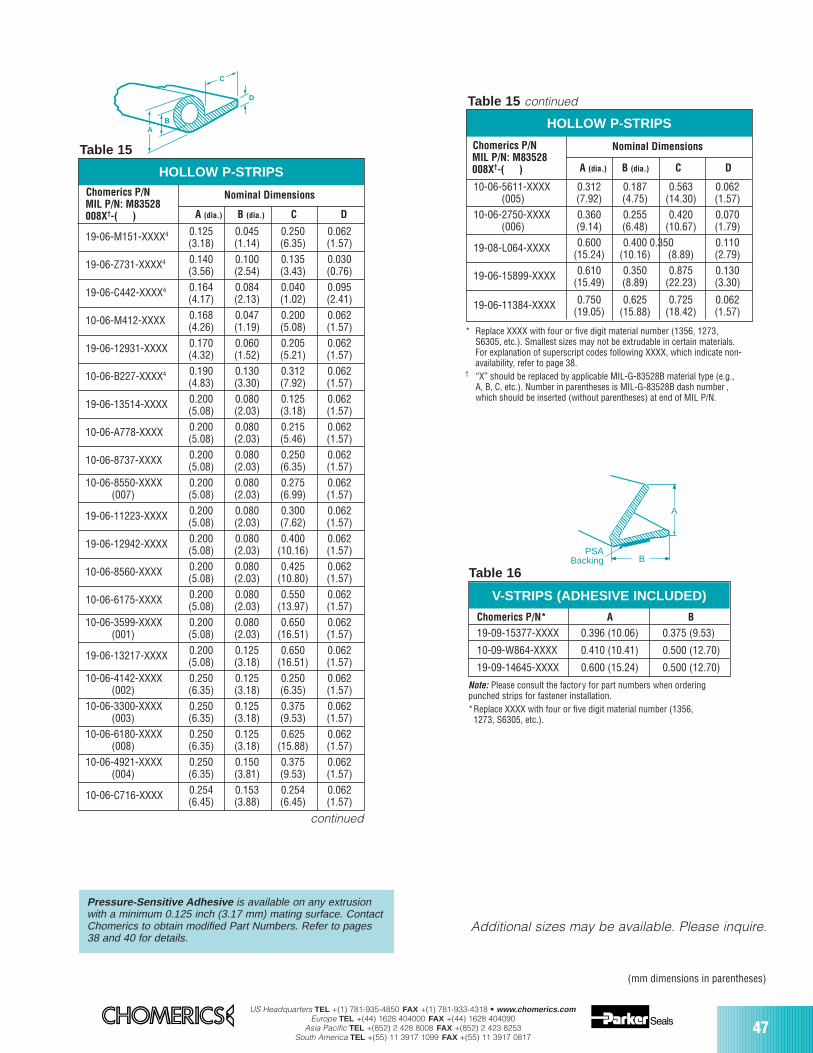
US Headquarters TEL +(1) 781-935-4850 FAX +(1) 781-933-4318 • www.chomerics.comEurope TEL +(44) 1628 404000 FAX +(44) 1628 404090
Asia Pacific TEL +(852) 2 428 8008 FAX +(852) 2 423 8253South America TEL +(55) 11 3917 1099 FAX +(55) 11 3917 0817
47
HOLLOW P-STRIPS
Nominal Dimensions
19-06-M151-XXXX4 0.125 0.045 0.250 0.062(3.18) (1.14) (6.35) (1.57)
19-06-Z731-XXXX4 0.140 0.100 0.135 0.030(3.56) (2.54) (3.43) (0.76)
19-06-C442-XXXX4 0.164 0.084 0.040 0.095(4.17) (2.13) (1.02) (2.41)
10-06-M412-XXXX 0.168 0.047 0.200 0.062(4.26) (1.19) (5.08) (1.57)
19-06-12931-XXXX 0.170 0.060 0.205 0.062(4.32) (1.52) (5.21) (1.57)
10-06-B227-XXXX4 0.190 0.130 0.312 0.062(4.83) (3.30) (7.92) (1.57)
19-06-13514-XXXX 0.200 0.080 0.125 0.062(5.08) (2.03) (3.18) (1.57)
10-06-A778-XXXX 0.200 0.080 0.215 0.062(5.08) (2.03) (5.46) (1.57)
10-06-8737-XXXX 0.200 0.080 0.250 0.062(5.08) (2.03) (6.35) (1.57)
10-06-8550-XXXX 0.200 0.080 0.275 0.062(007) (5.08) (2.03) (6.99) (1.57)
19-06-11223-XXXX 0.200 0.080 0.300 0.062(5.08) (2.03) (7.62) (1.57)
19-06-12942-XXXX 0.200 0.080 0.400 0.062(5.08) (2.03) (10.16) (1.57)
10-06-8560-XXXX 0.200 0.080 0.425 0.062(5.08) (2.03) (10.80) (1.57)
10-06-6175-XXXX 0.200 0.080 0.550 0.062(5.08) (2.03) (13.97) (1.57)
10-06-3599-XXXX 0.200 0.080 0.650 0.062(001) (5.08) (2.03) (16.51) (1.57)
19-06-13217-XXXX 0.200 0.125 0.650 0.062(5.08) (3.18) (16.51) (1.57)
10-06-4142-XXXX 0.250 0.125 0.250 0.062(002) (6.35) (3.18) (6.35) (1.57)
10-06-3300-XXXX 0.250 0.125 0.375 0.062(003) (6.35) (3.18) (9.53) (1.57)
10-06-6180-XXXX 0.250 0.125 0.625 0.062(008) (6.35) (3.18) (15.88) (1.57)
10-06-4921-XXXX 0.250 0.150 0.375 0.062(004) (6.35) (3.81) (9.53) (1.57)
10-06-C716-XXXX 0.254 0.153 0.254 0.062(6.45) (3.88) (6.45) (1.57)
BA
C
D
Table 15
* Replace XXXX with four or five digit material number (1356, 1273, S6305, etc.). Smallest sizes may not be extrudable in certain materials. For explanation of superscript codes following XXXX, which indicate non-availability, refer to page 38.
† “X” should be replaced by applicable MIL-G-83528B material type (e.g., A, B, C, etc.). Number in parentheses is MIL-G-83528B dash number , which should be inserted (without parentheses) at end of MIL P/N.
Pressure-Sensitive Adhesive is available on any extrusionwith a minimum 0.125 inch (3.17 mm) mating surface. ContactChomerics to obtain modified Part Numbers. Refer to pages38 and 40 for details.
Chomerics P/N* A B
19-09-15377-XXXX 0.396 (10.06) 0.375 (9.53)
10-09-W864-XXXX 0.410 (10.41) 0.500 (12.70)
19-09-14645-XXXX 0.600 (15.24) 0.500 (12.70)
Note: Please consult the factory for part numbers when orderingpunched strips for fastener installation.*Replace XXXX with four or five digit material number (1356,
1273, S6305, etc.).
V-STRIPS (ADHESIVE INCLUDED)
Table 16
HOLLOW P-STRIPS
Nominal Dimensions
10-06-5611-XXXX 0.312 0.187 0.563 0.062(005) (7.92) (4.75) (14.30) (1.57)
10-06-2750-XXXX 0.360 0.255 0.420 0.070(006) (9.14) (6.48) (10.67) (1.79)
19-08-L064-XXXX 0.600 0.400 0.350 0.110(15.24) (10.16) (8.89) (2.79)
19-06-15899-XXXX 0.610 0.350 0.875 0.130(15.49) (8.89) (22.23) (3.30)
19-06-11384-XXXX 0.750 0.625 0.725 0.062(19.05) (15.88) (18.42) (1.57)
Table 15 continued
A
BPSA
Backing
(mm dimensions in parentheses)
Additional sizes may be available. Please inquire.
A (dia.) B (dia.) C D
Chomerics P/N MIL P/N: M83528008X†-( )
A (dia.) B (dia.) C D
Chomerics P/N MIL P/N: M83528008X†-( )
continued
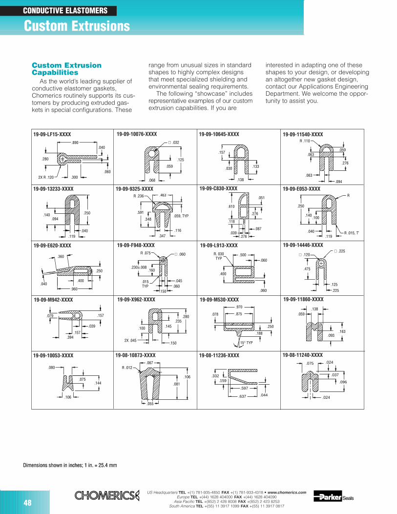
48US Headquarters TEL +(1) 781-935-4850 FAX +(1) 781-933-4318 • www.chomerics.com
Europe TEL +(44) 1628 404000 FAX +(44) 1628 404090Asia Pacific TEL +(852) 2 428 8008 FAX +(852) 2 423 8253
South America TEL +(55) 11 3917 1099 FAX +(55) 11 3917 0817
.280
2X R .120 .300.060
.040.890 ∅ .032
.125
.059
.068
.157
.030
.138
.133
R .110
.059
.276
.094
.063
.063
.140.094
.119.040
.250
.463
.059, TYP
.116.347
.348
.591
R .236
.250
.140.100
.040.119
R .015, TY
R
.250
.960
.400.040
.360R .075
.230±.008.160
.015TYP
∅ .060
.045.060
.150
R. 030TYP
.400
.500.060
.060
.970
.875
.250
.188
15° TYP
.078.079 .157
.394.157
.039 .100
2X .045.150
.145.235
.280
.475
.125
∅ .225
.225
∅ .120
.138.059
.093.163
.610
.118
.051
.276
.276.039
.087
.080
.144.075
.106
.067R .012
.106
.081
.055
.332.159
.044.637
.597
.075 .024
.037
.096
.024
Custom Extrusions
Custom ExtrusionCapabilities
As the world’s leading supplier ofconductive elastomer gaskets,Chomerics routinely supports its cus-tomers by producing extruded gas-kets in special configurations. These
range from unusual sizes in standardshapes to highly complex designsthat meet specialized shielding andenvironmental sealing requirements.
The following “showcase” includesrepresentative examples of our customextrusion capabilities. If you are
interested in adapting one of theseshapes to your design, or developingan altogether new gasket design,contact our Applications EngineeringDepartment. We welcome the oppor-tunity to assist you.
Dimensions shown in inches; 1 in. = 25.4 mmDimensions shown in inches; 1 in. = 25.4 mm
19-09-LF15-XXXX 19-09-10076-XXXX 19-09-10645-XXXX 19-09-11540-XXXX
19-09-13233-XXXX 19-09-9325-XXXX 19-09-C830-XXXX 19-09-E053-XXXX
19-09-E620-XXXX 19-09-F948-XXXX 19-09-L913-XXXX 19-09-14446-XXXX
19-09-M942-XXXX 19-09-X962-XXXX 19-09-M530-XXXX 19-09-11860-XXXX
19-09-10053-XXXX 19-08-10873-XXXX 19-08-11236-XXXX 19-08-11240-XXXX
CONDUCTIVE ELASTOMERS
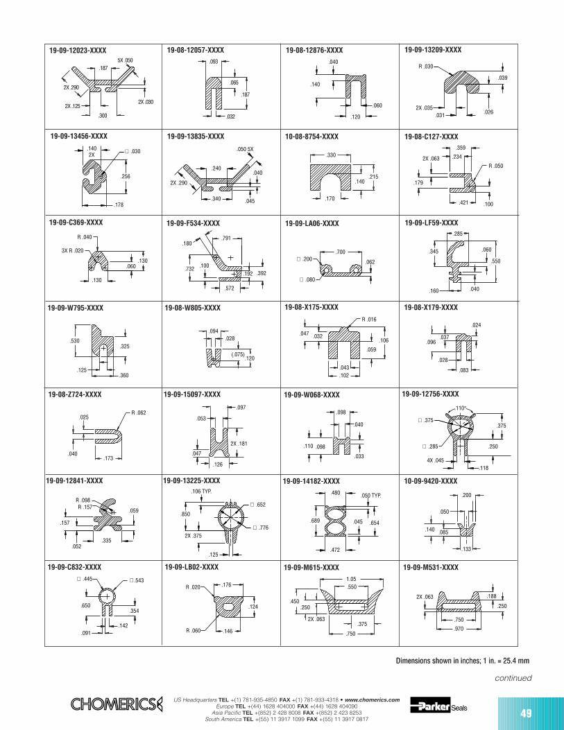
US Headquarters TEL +(1) 781-935-4850 FAX +(1) 781-933-4318 • www.chomerics.comEurope TEL +(44) 1628 404000 FAX +(44) 1628 404090
Asia Pacific TEL +(852) 2 428 8008 FAX +(852) 2 423 8253South America TEL +(55) 11 3917 1099 FAX +(55) 11 3917 0817
49
2X .290
2X .125
.300
2X .030
5X .050.187
.093
.065
.187
.032
.040
.140
.120
.060
R .030
2X .035.031 .026
.039
.1402X
∅ .030
.256
.178
.240
.340
.040
.045
.050 5X
2X .290
.330
.215.140
.170
.179
.421 .100
R .050
.359
.2342X .063
.130
3X R .020
R .040
.130.060
.572
.392.192
.791
.732 .100
.180
.700
.062
∅ .080
∅ .200
.285
.345
.160 .040
.550
.060
.360
.325
.125
.530
.120(.075)
.028.094
R .016
.106
.059
.043
.102
.032.047
.096.037
.028
.083
.024
.025
.040.173
R .062
2X .181
.126
.097
.053
.047.098
.033
.040
.098
.110 .250
∅ .375
∅ .285
4X .045.118
.375
.110°
.059
R .098R .157
.157
.052.335
.850
.106 TYP.
∅ .652
∅ .7762X .375
.125
.480 .050 TYP.
.689
.472
.045 .654
.050
.140 .085
.133
.200
∅ .445 ∅.543
.354.650
.091.142
.176
.124
.146R .060
R .0201.05.550
.450.250
2X .063.375
.750
.750
2X .063
.970
.188
.250
Dimensions shown in inches; 1 in. = 25.4 mmDimensions shown in inches; 1 in. = 25.4 mm
19-09-12023-XXXX 19-08-12057-XXXX 19-08-12876-XXXX 19-09-13209-XXXX
19-09-13456-XXXX 19-09-13835-XXXX 10-08-8754-XXXX 19-08-C127-XXXX
19-09-C369-XXXX 19-09-F534-XXXX 19-09-LA06-XXXX 19-09-LF59-XXXX
19-09-W795-XXXX 19-08-W805-XXXX 19-08-X175-XXXX 19-08-X179-XXXX
19-08-Z724-XXXX 19-09-15097-XXXX 19-09-W068-XXXX 19-09-12756-XXXX
19-09-12841-XXXX 19-09-13225-XXXX 19-09-14182-XXXX 10-09-9420-XXXX
19-09-C832-XXXX 19-09-LB02-XXXX 19-09-M615-XXXX 19-09-M531-XXXX
continued
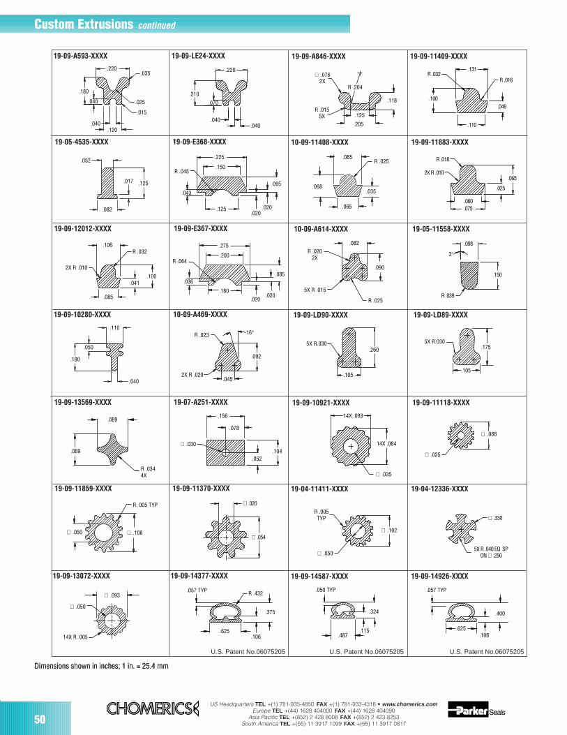
US Headquarters TEL +(1) 781-935-4850 FAX +(1) 781-933-4318 • www.chomerics.comEurope TEL +(44) 1628 404000 FAX +(44) 1628 404090
Asia Pacific TEL +(852) 2 428 8008 FAX +(852) 2 423 8253South America TEL +(55) 11 3917 1099 FAX +(55) 11 3917 081750
.035
.025
.015
.120.040
.040
.180
.220
.210
.070
.040
.220
.040
R .032.131
R .016
.049
.110
.100
.065
R .018
2X R .010
.060
.075
.025
R .032.106
2X R .010
.100.041
.085
.052
.017 .125
.082 .125.020
.020
.095
.043
R .045
.225
.150R .025
.085
.035.068
.065
.036
R .064
.275
.200
.180
.020.020
.085
R .0202X
5X R .015
R .025
.082
.090
3°
.098
.150
R .039
.205
R .0155X
.118
R .204
∅ .0762X
.125
R .023
2X R .020.045
.092
16°
.105
.2605X R.030 5X R.030
.175
.105
.089
R .0344X
.089
.156
.078
∅ .030
.052.104
∅ .035
14X .093
14X .084
∅ .025
∅ .088
.110
.040
.180
.050
∅ .020
∅ .054∅ .102
∅ .050
R .005TYP ∅ .330
5X R .040 EQ SPON ∅ .250
∅ .108∅ .050
R. 005 TYP
∅ .093
∅ .050
14X R. 005
.375
R .432.057 TYP
.106.625 .115
.324
.050 TYP
.487 .106.625
.057 TYP
.400
U.S. Patent No.06075205
Dimensions shown in inches; 1 in. = 25.4 mmDimensions shown in inches; 1 in. = 25.4 mm
19-09-A593-XXXX 19-09-LE24-XXXX 19-09-A846-XXXX 19-09-11409-XXXX
19-05-4535-XXXX 19-09-E368-XXXX 10-09-11408-XXXX 19-09-11883-XXXX
19-09-12012-XXXX 19-09-E367-XXXX 10-09-A614-XXXX 19-05-11558-XXXX
19-09-10280-XXXX 10-09-A469-XXXX 19-09-LD90-XXXX 19-09-LD89-XXXX
19-09-13569-XXXX 19-07-A251-XXXX 19-09-10921-XXXX 19-09-11118-XXXX
19-09-11859-XXXX 19-09-11370-XXXX 19-04-11411-XXXX 19-04-12336-XXXX
19-09-13072-XXXX 19-09-14377-XXXX 19-09-14587-XXXX 19-09-14926-XXXX
Custom Extrusions continued
U.S. Patent No.06075205 U.S. Patent No.06075205
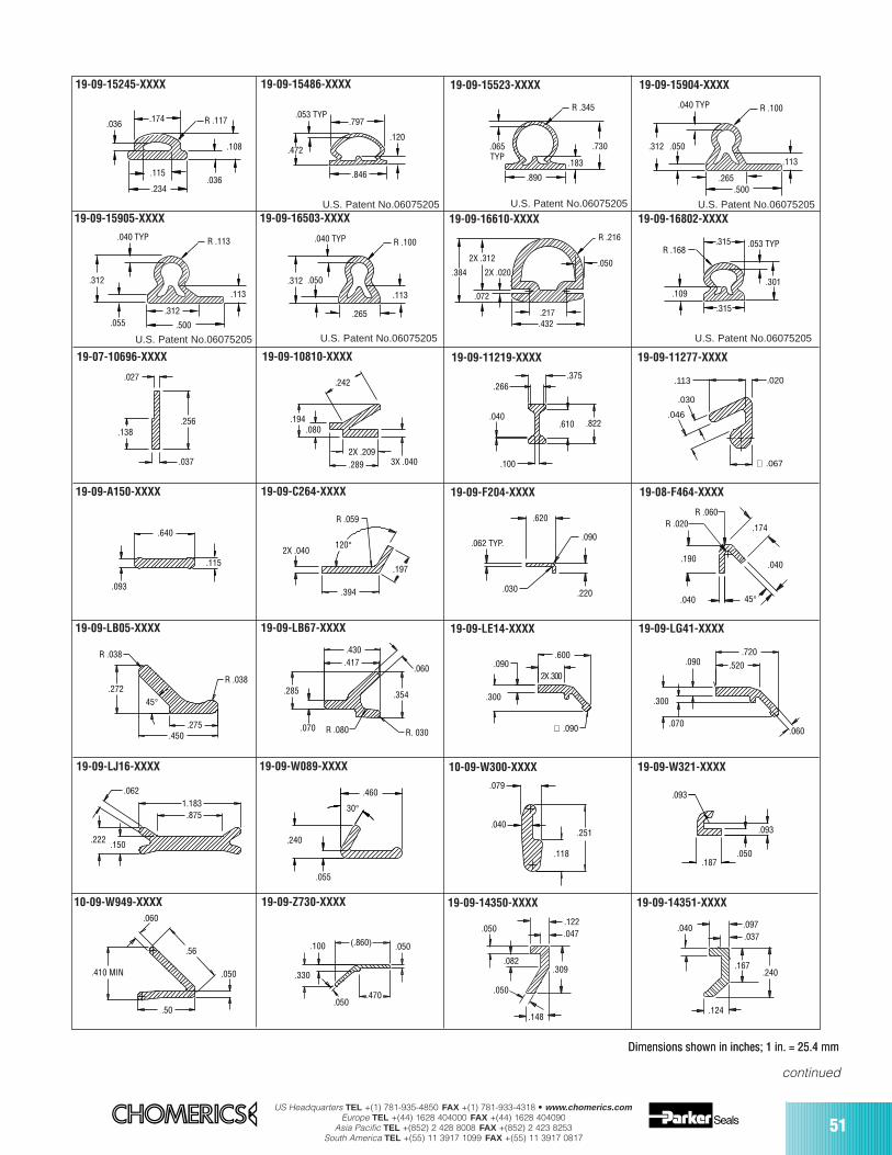
US Headquarters TEL +(1) 781-935-4850 FAX +(1) 781-933-4318 • www.chomerics.comEurope TEL +(44) 1628 404000 FAX +(44) 1628 404090
Asia Pacific TEL +(852) 2 428 8008 FAX +(852) 2 423 8253South America TEL +(55) 11 3917 1099 FAX +(55) 11 3917 0817
51
.036.174
.115
.234
.108
.036
R .117 .797.053 TYP
.846
.472.120
R .345
.730
.890
.183
.065TYP
.500.265
.050
.040 TYP R .100
.312
.113
.500
.113
.040 TYP R .113
.312
.312.055
R .100
.312
.265
.113
.050
.040 TYP
2X .020
.072
.384
2X .312
R .216
.432.217
.050
.109
.315
.315 .053 TYPR .168
.301
.027
.138.256
.037
.242
.194.080
2X .209.289 3X .040
.266.375
.822.610.040
.100
.020
∅ .067
.046
.030
.113
.640
.115
.093
2X .040
.394
.197
R .059
120°
.620
.090
.220.030
.062 TYP.
.040
.040
45°
.174
R .060R .020
.190
R .038
.275.450
45°.272
R .038
R. 030
.354
.060
R .080.070
.285
.430.417
.600
2X .300
∅ .090
.300
.090.720
.520
.060.070
.300
.090
1.183.875
.062
.222 .150 .240
.055
30°
.460.079
.251.040
.118
.093
.187 .050
.093
.060
.56
.050
.50
.410 MIN
(.860) .050
.470.050
.330
.100
.082.309
.148
.050
.050
.122
.047.040
.167.240
.124
.097.037
Dimensions shown in inches; 1 in. = 25.4 mmDimensions shown in inches; 1 in. = 25.4 mm
19-09-15245-XXXX 19-09-15486-XXXX 19-09-15523-XXXX 19-09-15904-XXXX
19-07-10696-XXXX 19-09-10810-XXXX 19-09-11219-XXXX 19-09-11277-XXXX
19-09-15905-XXXX 19-09-16503-XXXX 19-09-16610-XXXX 19-09-16802-XXXX
19-09-A150-XXXX 19-09-C264-XXXX 19-09-F204-XXXX 19-08-F464-XXXX
19-09-LB05-XXXX 19-09-LB67-XXXX 19-09-LE14-XXXX 19-09-LG41-XXXX
19-09-LJ16-XXXX 19-09-W089-XXXX 10-09-W300-XXXX 19-09-W321-XXXX
10-09-W949-XXXX 19-09-Z730-XXXX 19-09-14350-XXXX 19-09-14351-XXXX
continued
U.S. Patent No.06075205 U.S. Patent No.06075205 U.S. Patent No.06075205
U.S. Patent No.06075205 U.S. Patent No.06075205 U.S. Patent No.06075205
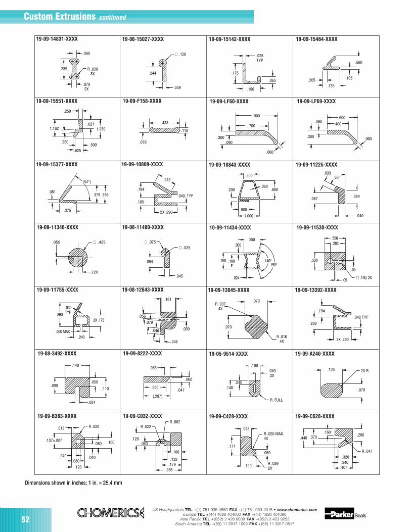
US Headquarters TEL +(1) 781-935-4850 FAX +(1) 781-933-4318 • www.chomerics.comEurope TEL +(44) 1628 404000 FAX +(44) 1628 404090
Asia Pacific TEL +(852) 2 428 8008 FAX +(852) 2 423 8253South America TEL +(55) 11 3917 1099 FAX +(55) 11 3917 0817
52
R .0308X
.289
.060
.0702X .059
.244
∅ .126
.150
.175
.065
.025TYP
.105.205.735
.560
1.162 1.250
.625.500
.250
.621
.250
.433
.079
.118
.900
.700
.060
.090.300
.400
.060
.600.090
.300
.375
.379.081
.396
(54°) .242
.040, TYP
2X .290
.105
.194
.500
.200.060
.880
1.000
.500
.03365°
.084
.040
.067
.059
.220
∅ .425
.045
∅ .025∅ .075
.094
.250.030
.250 .190
.024
140°150°
.590.282
.05
.05 ∅ .140, 2X
.508
2X .175
.240.060 MAX
.360
.030TYP.
.161
.079
.056
.039.046
.046
.070
R .0374X
.070
R .0164X
.194
.200
.040 TYP
2X .290
.140
.090.050
.110
.024
.065
.062
.047
(.297)
.250
.100.0402X
R. FULL
.040.148
.126 2X R
.079
.040
.100.080
R .020.015
.137±.007
.040
.120.080
R .062
.100
.132.179
.236
.040.120
R .022
R .020 MAX.4X
.059
R .0392X
.140
.171
.098
.407.340.320
R .047
.286.440 .370
.160
Dimensions shown in inches; 1 in. = 25.4 mmDimensions shown in inches; 1 in. = 25.4 mm
19-09-14831-XXXX 19-06-15027-XXXX 19-09-15142-XXXX 19-09-15464-XXXX
19-09-15551-XXXX 19-09-F158-XXXX 19-09-LF60-XXXX 19-09-LF69-XXXX
19-09-15377-XXXX 19-09-10809-XXXX 19-09-10843-XXXX 19-09-11225-XXXX
19-09-11346-XXXX 19-06-11400-XXXX 10-09-11434-XXXX 19-09-11530-XXXX
19-09-11755-XXXX 19-08-12643-XXXX 19-09-13045-XXXX 19-09-13392-XXXX
19-08-3492-XXXX 19-09-8222-XXXX 19-05-9514-XXXX 19-09-A240-XXXX
19-09-B363-XXXX 19-09-C032-XXXX 19-09-C428-XXXX 19-09-C628-XXXX
Custom Extrusions continued

US Headquarters TEL +(1) 781-935-4850 FAX +(1) 781-933-4318 • www.chomerics.comEurope TEL +(44) 1628 404000 FAX +(44) 1628 404090
Asia Pacific TEL +(852) 2 428 8008 FAX +(852) 2 423 8253South America TEL +(55) 11 3917 1099 FAX +(55) 11 3917 0817
53
.076
R .153.119
R .060
R .015
.050
.190
(30°)
.190(1.125)
∅ .055
∅ .085
.020
.145
.530
∅ .125
.088
.360
.295
.155
.126
.0254X
.300 .030
R .039TYP
.030 TYP
.120
.120.225
.181
.254
.079
.035
.024TYP .189
.028
.166
.057
.197
.248
.315
.077.266
.048
.039 TYP
∅ .060
.230
.075
.160
.060
.040, 2X
4X .0452X .030
.315
.197
.039TYP
.268
2X .067
2X R .031
.031 1.660
.515
.050 TYPR.170
2X .521
.447R.200
.395
.285
.535
.035 TYP
.085
(59°)
R .155
.514
.312
.400 .053
.062 TYP
(58°)R .218
.327
.197
.341
.439
.187
.110
.130.067
R .030, 2X
∅ .050
R .011TYP
.039CTRD.
.021CTRD.
.095.063
.038
.068
.020
.043
.741
.060, 2X
.280, 3X
∅ .351
∅ .421
.043
.097
2X R .077
∅ .260∅ .140
.322
.090R .015
.240
.175.215
.030
.090
.180
.110
∅ .037
.049
.110
.131
.100
R .050
.375
.467.815
.174
.090
.105
.169
.025
.115.053
∅ .055
.124
R .073
.312
R .096
R .156
.062
.506
Dimensions shown in inches; 1 in. = 25.4 mmDimensions shown in inches; 1 in. = 25.4 mm
19-05-E328-XXXX 19-08-F676-XXXX 19-09-W517-XXXX 19-09-X681-XXXX
19-06-11864-XXXX 19-09-13946-XXXX 19-06-14313-XXXX 19-09-15380-XXXX
19-09-15786-XXXX 19-09-16750-XXXX 19-07-W470-XXXX 19-09-13997-XXXX
19-09-15562-XXXX 19-09-15862-XXXX 19-09-15895-XXXX 19-09-15937-XXXX
19-09-16047-XXXX 19-09-16072-XXXX 19-09-16166-XXXX 19-09-16336-XXXX
19-06-L386-XXXX 19-09-10357-XXXX 19-09-11261-XXXX 19-09-12999-XXXX
19-09-11367-XXXX 19-09-11389-XXXX 19-09-11735-XXXX 19-06-13540-XXXX
continued
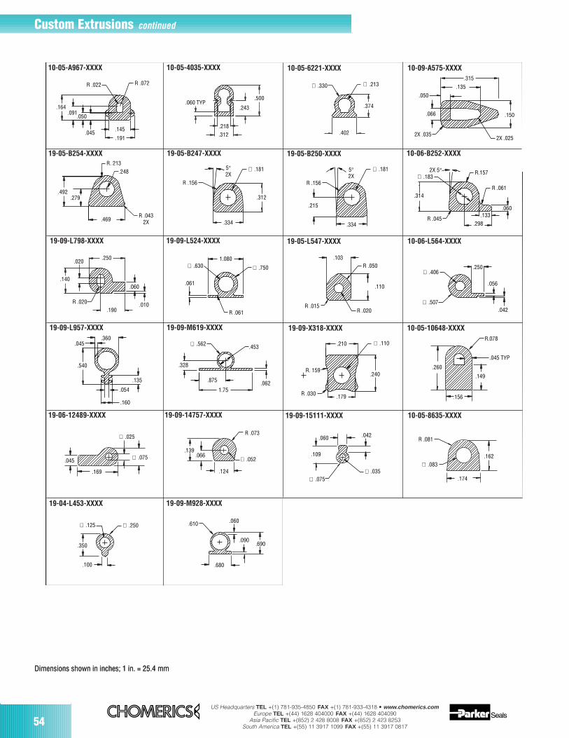
US Headquarters TEL +(1) 781-935-4850 FAX +(1) 781-933-4318 • www.chomerics.comEurope TEL +(44) 1628 404000 FAX +(44) 1628 404090
Asia Pacific TEL +(852) 2 428 8008 FAX +(852) 2 423 8253South America TEL +(55) 11 3917 1099 FAX +(55) 11 3917 081754
.500
.243.060 TYP
.218.312
∅ .330 ∅ .213
.374
.402
.315
.135
.150
.050
.066
2X .0352X .025
.045.145
.191
R .072R .022
.164.091
.050
∅ .181
.312
.334
5°2X
R .156
∅ .1815°2X
.334
R .156
.215 .060
∅ .1832X 5°
.314
R.157
R .061
.133.298
R .045
.248R. 213
.492.279
R .0432X.469
∅ .630 ∅ .750
.061
R .061
1.080 .103
R .015R .020
.110
R .050∅ .406
∅ .507
.250
.056
.042
.020.250
.140
R .020.190
.010
.060
.045
.540
.360
.135
.054
.160
.328
.875
1.75.062
.453∅ .562 .210 ∅ .110
.240
.179
R. 159
R .030
R.078
.045 TYP
.156
.149
.260
.045
.169
∅ .025
∅ .075 ∅ .052
R .073
.124
.066.139
.060 .042
.109
∅ .075∅ .035
∅ .083
R .081
.174
.162
.350
.100
∅ .250∅ .125 .610 .060
.690.090
.680
Dimensions shown in inches; 1 in. = 25.4 mmDimensions shown in inches; 1 in. = 25.4 mm
10-05-A967-XXXX 10-05-4035-XXXX 10-05-6221-XXXX 10-09-A575-XXXX
19-05-B254-XXXX 19-05-B247-XXXX 19-05-B250-XXXX 10-06-B252-XXXX
19-09-L798-XXXX 19-09-L524-XXXX 19-05-L547-XXXX 10-06-L564-XXXX
19-09-L957-XXXX 19-09-M619-XXXX 19-09-X318-XXXX 10-05-10648-XXXX
19-06-12489-XXXX 19-09-14757-XXXX 19-09-15111-XXXX 10-05-8635-XXXX
19-04-L453-XXXX 19-09-M928-XXXX
Custom Extrusions continued
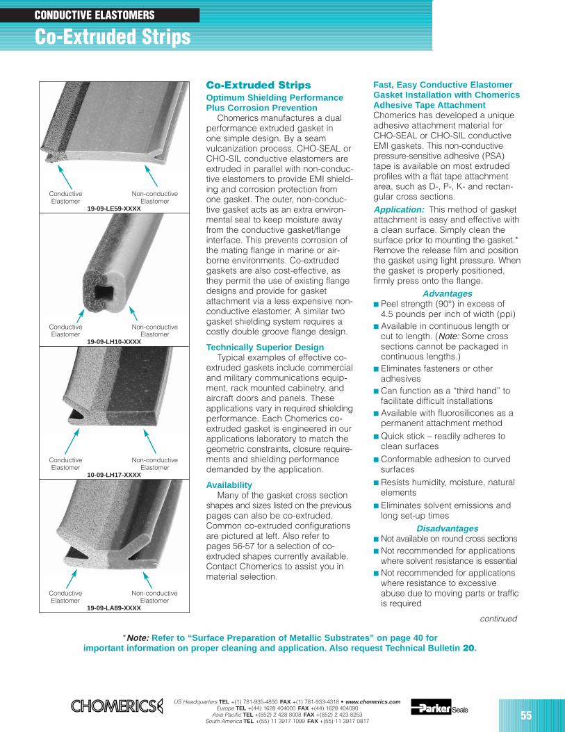
US Headquarters TEL +(1) 781-935-4850 FAX +(1) 781-933-4318 • www.chomerics.comEurope TEL +(44) 1628 404000 FAX +(44) 1628 404090
Asia Pacific TEL +(852) 2 428 8008 FAX +(852) 2 423 8253South America TEL +(55) 11 3917 1099 FAX +(55) 11 3917 0817
55
Co-Extruded StripsCONDUCTIVE ELASTOMERS
Co-Extruded StripsOptimum Shielding PerformancePlus Corrosion Prevention
Chomerics manufactures a dualperformance extruded gasket inone simple design. By a seamvulcanization process, CHO-SEAL orCHO-SIL conductive elastomers areextruded in parallel with non-conduc-tive elastomers to provide EMI shield-ing and corrosion protection fromone gasket. The outer, non-conduc-tive gasket acts as an extra environ-mental seal to keep moisture awayfrom the conductive gasket/flangeinterface. This prevents corrosion ofthe mating flange in marine or air-borne environments. Co-extrudedgaskets are also cost-effective, asthey permit the use of existing flangedesigns and provide for gasketattachment via a less expensive non-conductive elastomer. A similar twogasket shielding system requires acostly double groove flange design.
Technically Superior DesignTypical examples of effective co-
extruded gaskets include commercialand military communications equip-ment, rack mounted cabinetry, andaircraft doors and panels. Theseapplications vary in required shieldingperformance. Each Chomerics co-extruded gasket is engineered in ourapplications laboratory to match thegeometric constraints, closure require-ments and shielding performancedemanded by the application.
AvailabilityMany of the gasket cross section
shapes and sizes listed on the previouspages can also be co-extruded.Common co-extruded configurationsare pictured at left. Also refer topages 56-57 for a selection of co-extruded shapes currently available.Contact Chomerics to assist you inmaterial selection.
Conductive Non-conductiveElastomer Elastomer
19-09-LE59-XXXX
Conductive Non-conductiveElastomer Elastomer
19-09-LH10-XXXX
Conductive Non-conductiveElastomer Elastomer
10-09-LH17-XXXX
Conductive Non-conductiveElastomer Elastomer
19-09-LA89-XXXX
Fast, Easy Conductive ElastomerGasket Installation with ChomericsAdhesive Tape AttachmentChomerics has developed a uniqueadhesive attachment material forCHO-SEAL or CHO-SIL conductiveEMI gaskets. This non-conductivepressure-sensitive adhesive (PSA)tape is available on most extrudedprofiles with a flat tape attachmentarea, such as D-, P-, K- and rectan-gular cross sections. Application: This method of gasketattachment is easy and effective witha clean surface. Simply clean thesurface prior to mounting the gasket.*Remove the release film and positionthe gasket using light pressure. Whenthe gasket is properly positioned,firmly press onto the flange.
Advantages Peel strength (90°) in excess of
4.5 pounds per inch of width (ppi) Available in continuous length or
cut to length. (Note: Some crosssections cannot be packaged incontinuous lengths.)
Eliminates fasteners or otheradhesives
Can function as a “third hand” tofacilitate difficult installations
Available with fluorosilicones as apermanent attachment method
Quick stick – readily adheres toclean surfaces
Conformable adhesion to curvedsurfaces
Resists humidity, moisture, naturalelements
Eliminates solvent emissions andlong set-up times
Disadvantages Not available on round cross sections Not recommended for applications
where solvent resistance is essential Not recommended for applications
where resistance to excessiveabuse due to moving parts or trafficis required
*Note: Refer to “Surface Preparation of Metallic Substrates” on page 40 forimportant information on proper cleaning and application. Also request Technical Bulletin 20.
continued
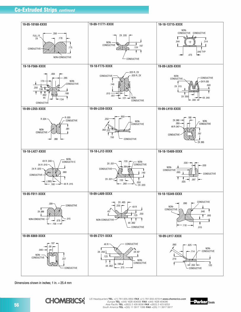
US Headquarters TEL +(1) 781-935-4850 FAX +(1) 781-933-4318 • www.chomerics.comEurope TEL +(44) 1628 404000 FAX +(44) 1628 404090
Asia Pacific TEL +(852) 2 428 8008 FAX +(852) 2 423 8253South America TEL +(55) 11 3917 1099 FAX +(55) 11 3917 081756
Co-Extruded Strips continued
.356
.178
.175CONDUCTIVE
NON-CONDUCTIVE
FULL R.2X
2X .335
.197.124
CONDUCTIVE
NON-CONDUCTIVE
.344
.475.040 TYP
.314
NON-CONDUCTIVE CONDUCTIVE
CONDUCTIVE
.015.078
.156
NON-CONDUCTIVE
2X .089
.039
.170
.484
.285
.188
.134
.0624X
.136.250
CONDUCTIVE
NON-CONDUCTIVE
CONDUCTIVE
NON-CONDUCTIVE
.025 R, 2X.020 R, 2X
.140
.015.051
.121
2X .315
NON-CONDUCTIVE CONDUCTIVE
2X R .035
4X .040
.040
.3002X .050
NON-CONDUCTIVE
CONDUCTIVE
4X .062
.250.125
4X R
45°
2X .485.220
R .024R .020
.091
.090
CONDUCTIVE
NON-CONDUCTIVE
.950
NON-CONDUCTIVE
CONDUCTIVE.150
.062.222
.250 2X .090.050
4X R .047
NON-CONDUCTIVE
.180
.187
2X .065
CONDUCTIVE
4X R .040NON-
CONDUCTIV E
.080
4X R .015.160(.080)
CONDUCTIVE
2X R .020
2X R .010NON-
CONDUCTIVE
.140
.0502X .020.260
.1302X .031
CONDUCTIVE
2X .031.120
.084
.187
.227
CONDUCTIVE
NON-CONDUCTIVE
.040.09
.030.030
.097
.093
.025
NON-CONDUCTIVE
CONDUCTIVE
.090
.040
.015.118
.093
CONDUCTIVE
NON-CONDUCTIVE
CONDUCTIVE
2X 45°
NON-CONDUCTIVE
.375.188
4X .062
.125
2X .250
4X R
NON-CONDUCTIVE
.120CONDUCTIVE
.350
.270
.625
.114
.060
Dimensions shown in inches; 1 in. = 25.4 mmDimensions shown in inches; 1 in. = 25.4 mm
19-05-10168-XXXX 19-09-11771-XXXX 19-18-13715-XXXX
19-18-F566-XXXX 19-18-F775-XXXX 19-09-L628-XXXX
19-09-LD55-XXXX 19-09-LE59-XXXX 19-09-LH10-XXXX
19-18-LH27-XXXX 19-18-LJ12-XXXX 19-18-15489-XXXX
19-05-F011-XXXX 19-09-LA89-XXXX 19-18-15349-XXXX
19-09-X869-XXXX 19-09-Z721-XXXX 10-09-LH17-XXXX
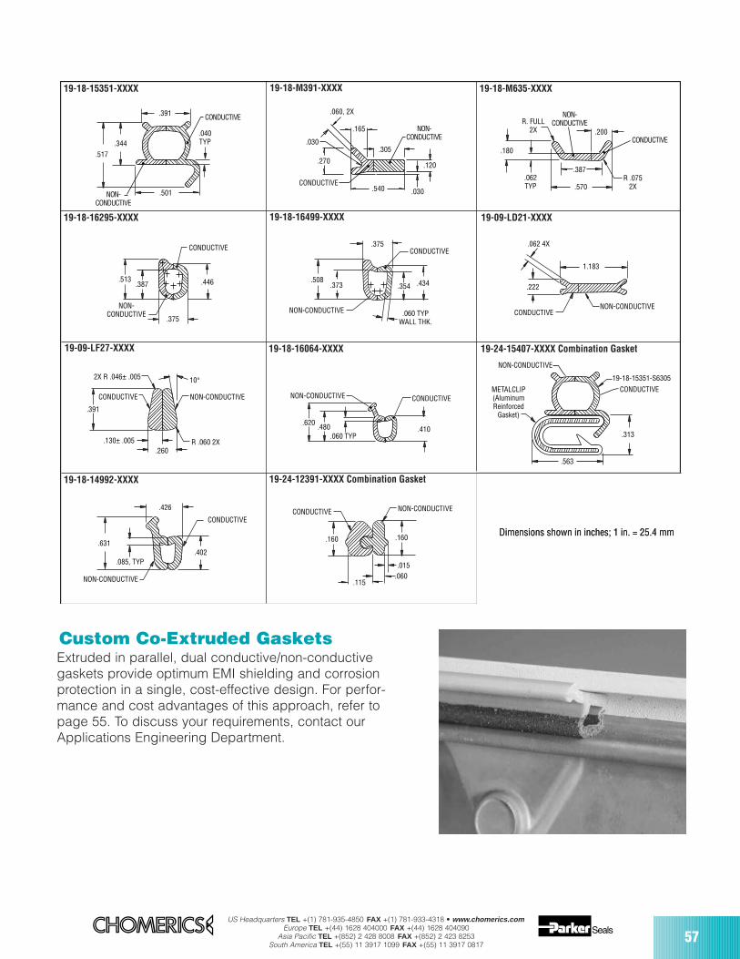
US Headquarters TEL +(1) 781-935-4850 FAX +(1) 781-933-4318 • www.chomerics.comEurope TEL +(44) 1628 404000 FAX +(44) 1628 404090
Asia Pacific TEL +(852) 2 428 8008 FAX +(852) 2 423 8253South America TEL +(55) 11 3917 1099 FAX +(55) 11 3917 0817
57
.160
.015 .060
.115
NON-CONDUCTIVE CONDUCTIVE
.160
NON-CONDUCTIVE
CONDUCTIVE
.085, TYP
.631
.426
.402
.391
.040 TYP
.501
.344.517
CONDUCTIVE
NON-CONDUCTIVE
.313
.563
19-18-15351-S6305
CONDUCTIVEMETALCLIP(AluminumReinforced
Gasket)
NON-CONDUCTIVE
NON-CONDUCTIVE CONDUCTIVE
.620.480
.060 TYP.410
NON-CONDUCTIVE
CONDUCTIVE
.375
.387 .446.513
NON-CONDUCTIVE
CONDUCTIVE.375
.373.508
.354 .434
.060 TYPWALL THK.
.062 4X
1.183
NON-CONDUCTIVECONDUCTIVE
.222
R .060 2X
10°
NON-CONDUCTIVECONDUCTIVE
2X R .046± .005
.130± .005
.391
.260
.570R .075
2X.062 TYP
R. FULL 2X
.387
.200
.180CONDUCTIVE
NON-CONDUCTIVE
.060, 2X
.165
.030
.270
CONDUCTIVE
.305
.120
.030.540
NON-CONDUCTIVE
Dimensions shown in inches; 1 in. = 25.4 mmDimensions shown in inches; 1 in. = 25.4 mm
Custom Co-Extruded GasketsExtruded in parallel, dual conductive/non-conductivegaskets provide optimum EMI shielding and corrosionprotection in a single, cost-effective design. For perfor-mance and cost advantages of this approach, refer topage 55. To discuss your requirements, contact ourApplications Engineering Department.
19-18-15351-XXXX 19-18-M391-XXXX 19-18-M635-XXXX
19-18-16295-XXXX 19-18-16499-XXXX 19-09-LD21-XXXX
19-09-LF27-XXXX 19-18-16064-XXXX 19-24-15407-XXXX Combination Gasket
19-24-12391-XXXX Combination Gasket19-18-14992-XXXX
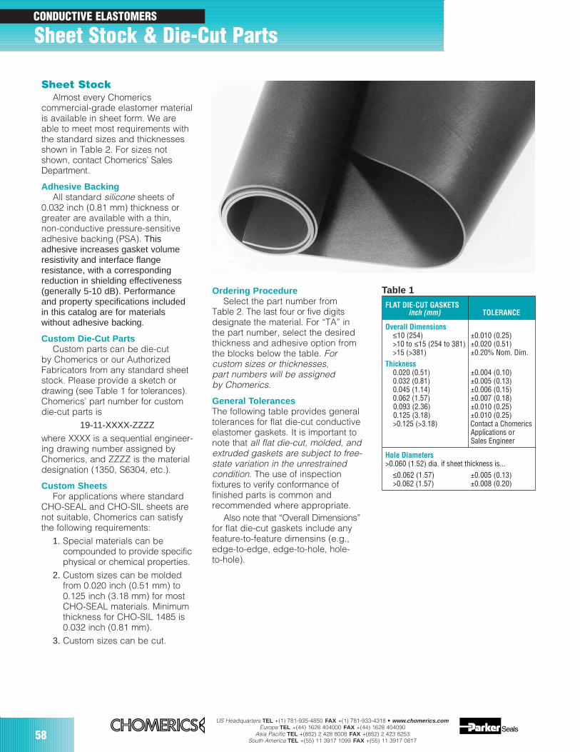
58US Headquarters TEL +(1) 781-935-4850 FAX +(1) 781-933-4318 • www.chomerics.com
Europe TEL +(44) 1628 404000 FAX +(44) 1628 404090Asia Pacific TEL +(852) 2 428 8008 FAX +(852) 2 423 8253
South America TEL +(55) 11 3917 1099 FAX +(55) 11 3917 0817
Sheet StockAlmost every Chomerics
commercial-grade elastomer materialis available in sheet form. We areable to meet most requirements withthe standard sizes and thicknessesshown in Table 2. For sizes notshown, contact Chomerics’ SalesDepartment.
Adhesive BackingAll standard silicone sheets of
0.032 inch (0.81 mm) thickness orgreater are available with a thin,non-conductive pressure-sensitiveadhesive backing (PSA). Thisadhesive increases gasket volumeresistivity and interface flangeresistance, with a correspondingreduction in shielding effectiveness(generally 5-10 dB). Performance and property specifications includedin this catalog are for materialswithout adhesive backing.
Custom Die-Cut PartsCustom parts can be die-cut
by Chomerics or our AuthorizedFabricators from any standard sheetstock. Please provide a sketch ordrawing (see Table 1 for tolerances).Chomerics’ part number for customdie-cut parts is
19-11-XXXX-ZZZZ
where XXXX is a sequential engineer-ing drawing number assigned byChomerics, and ZZZZ is the materialdesignation (1350, S6304, etc.).
Custom SheetsFor applications where standard
CHO-SEAL and CHO-SIL sheets arenot suitable, Chomerics can satisfythe following requirements:
1. Special materials can becompounded to provide specificphysical or chemical properties.
2. Custom sizes can be molded from 0.020 inch (0.51 mm) to0.125 inch (3.18 mm) for mostCHO-SEAL materials. Minimumthickness for CHO-SIL 1485 is0.032 inch (0.81 mm).
3. Custom sizes can be cut.
Ordering ProcedureSelect the part number from
Table 2. The last four or five digitsdesignate the material. For “TA” inthe part number, select the desiredthickness and adhesive option fromthe blocks below the table. Forcustom sizes or thicknesses,part numbers will be assignedby Chomerics.
General TolerancesThe following table provides generaltolerances for flat die-cut conductiveelastomer gaskets. It is important tonote that all flat die-cut, molded, andextruded gaskets are subject to free-state variation in the unrestrainedcondition. The use of inspectionfixtures to verify conformance offinished parts is common andrecommended where appropriate.
Also note that “Overall Dimensions”for flat die-cut gaskets include anyfeature-to-feature dimensins (e.g.,edge-to-edge, edge-to-hole, hole-to-hole).
FLAT DIE-CUT GASKETSinch (mm) TOLERANCE
Overall Dimensions≤10 (254) ±0.010 (0.25)>10 to ≤15 (254 to 381) ±0.020 (0.51)>15 (>381) ±0.20% Nom. Dim.
Thickness0.020 (0.51) ±0.004 (0.10)0.032 (0.81) ±0.005 (0.13)0.045 (1.14) ±0.006 (0.15)0.062 (1.57) ±0.007 (0.18)0.093 (2.36) ±0.010 (0.25)0.125 (3.18) ±0.010 (0.25)>0.125 (>3.18) Contact a Chomerics
Applications or Sales Engineer
Hole Diameters>0.060 (1.52) dia. if sheet thickness is...
≤0.062 (1.57) ±0.005 (0.13)>0.062 (1.57) ±0.008 (0.20)
Table 1
Sheet Stock & Die-Cut Parts CONDUCTIVE ELASTOMERS
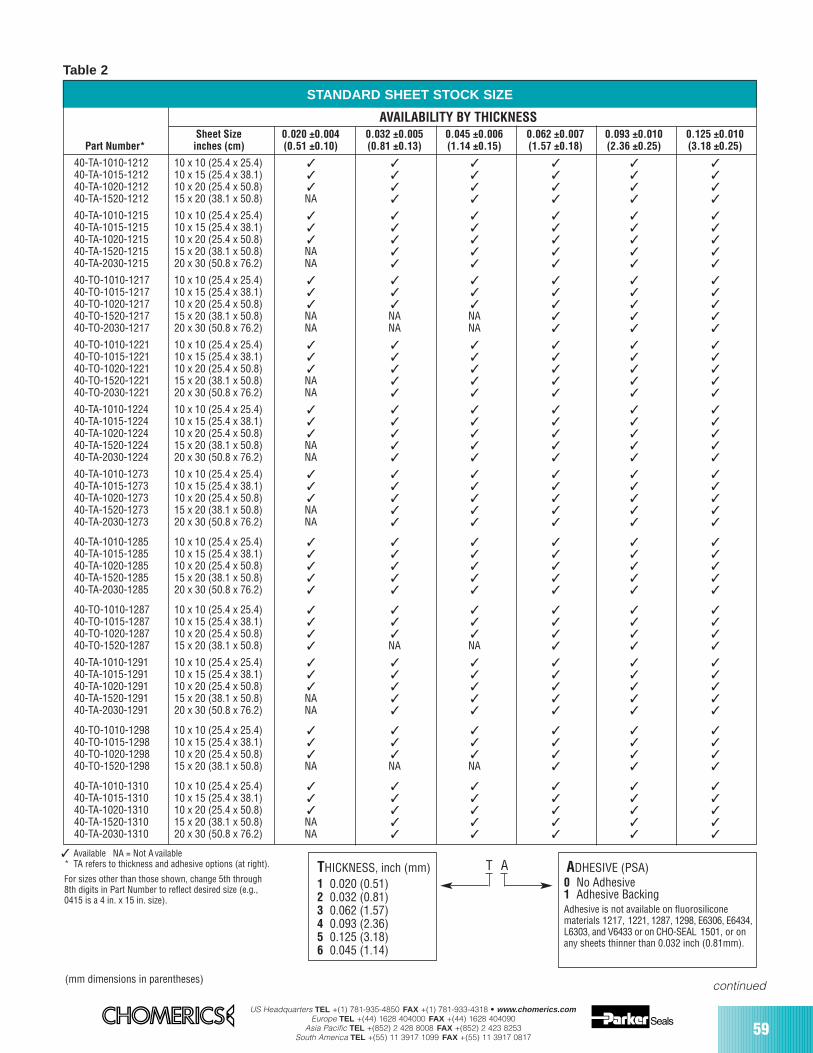
US Headquarters TEL +(1) 781-935-4850 FAX +(1) 781-933-4318 • www.chomerics.comEurope TEL +(44) 1628 404000 FAX +(44) 1628 404090
Asia Pacific TEL +(852) 2 428 8008 FAX +(852) 2 423 8253South America TEL +(55) 11 3917 1099 FAX +(55) 11 3917 0817
59
STANDARD SHEET STOCK SIZE
AVAILABILITY BY THICKNESSSheet Size 0.020 ±0.004 0.032 ±0.005 0.045 ±0.006 0.062 ±0.007 0.093 ±0.010 0.125 ±0.010
Part Number* inches (cm) (0.51 ±0.10) (0.81 ±0.13) (1.14 ±0.15) (1.57 ±0.18) (2.36 ±0.25) (3.18 ±0.25)
40-TA-1010-1212 10 x 10 (25.4 x 25.4) 40-TA-1015-1212 10 x 15 (25.4 x 38.1) 40-TA-1020-1212 10 x 20 (25.4 x 50.8) 40-TA-1520-1212 15 x 20 (38.1 x 50.8) NA
40-TA-1010-1215 10 x 10 (25.4 x 25.4) 40-TA-1015-1215 10 x 15 (25.4 x 38.1) 40-TA-1020-1215 10 x 20 (25.4 x 50.8) 40-TA-1520-1215 15 x 20 (38.1 x 50.8) NA 40-TA-2030-1215 20 x 30 (50.8 x 76.2) NA
40-TO-1010-1217 10 x 10 (25.4 x 25.4) 40-TO-1015-1217 10 x 15 (25.4 x 38.1) 40-TO-1020-1217 10 x 20 (25.4 x 50.8) 40-TO-1520-1217 15 x 20 (38.1 x 50.8) NA NA NA 40-TO-2030-1217 20 x 30 (50.8 x 76.2) NA NA NA
40-TO-1010-1221 10 x 10 (25.4 x 25.4) 40-TO-1015-1221 10 x 15 (25.4 x 38.1) 40-TO-1020-1221 10 x 20 (25.4 x 50.8) 40-TO-1520-1221 15 x 20 (38.1 x 50.8) NA 40-TO-2030-1221 20 x 30 (50.8 x 76.2) NA
40-TA-1010-1224 10 x 10 (25.4 x 25.4) 40-TA-1015-1224 10 x 15 (25.4 x 38.1) 40-TA-1020-1224 10 x 20 (25.4 x 50.8) 40-TA-1520-1224 15 x 20 (38.1 x 50.8) NA 40-TA-2030-1224 20 x 30 (50.8 x 76.2) NA
40-TA-1010-1273 10 x 10 (25.4 x 25.4) 40-TA-1015-1273 10 x 15 (25.4 x 38.1) 40-TA-1020-1273 10 x 20 (25.4 x 50.8) 40-TA-1520-1273 15 x 20 (38.1 x 50.8) NA 40-TA-2030-1273 20 x 30 (50.8 x 76.2) NA
40-TA-1010-1285 10 x 10 (25.4 x 25.4) 40-TA-1015-1285 10 x 15 (25.4 x 38.1) 40-TA-1020-1285 10 x 20 (25.4 x 50.8) 40-TA-1520-1285 15 x 20 (38.1 x 50.8) 40-TA-2030-1285 20 x 30 (50.8 x 76.2)
40-TO-1010-1287 10 x 10 (25.4 x 25.4) 40-TO-1015-1287 10 x 15 (25.4 x 38.1) 40-TO-1020-1287 10 x 20 (25.4 x 50.8) 40-TO-1520-1287 15 x 20 (38.1 x 50.8) NA NA
40-TA-1010-1291 10 x 10 (25.4 x 25.4) 40-TA-1015-1291 10 x 15 (25.4 x 38.1) 40-TA-1020-1291 10 x 20 (25.4 x 50.8) 40-TA-1520-1291 15 x 20 (38.1 x 50.8) NA 40-TA-2030-1291 20 x 30 (50.8 x 76.2) NA
40-TO-1010-1298 10 x 10 (25.4 x 25.4) 40-TO-1015-1298 10 x 15 (25.4 x 38.1) 40-TO-1020-1298 10 x 20 (25.4 x 50.8) 40-TO-1520-1298 15 x 20 (38.1 x 50.8) NA NA NA
40-TA-1010-1310 10 x 10 (25.4 x 25.4) 40-TA-1015-1310 10 x 15 (25.4 x 38.1) 40-TA-1020-1310 10 x 20 (25.4 x 50.8) 40-TA-1520-1310 15 x 20 (38.1 x 50.8) NA 40-TA-2030-1310 20 x 30 (50.8 x 76.2) NA
For sizes other than those shown, change 5th through8th digits in Part Number to reflect desired size (e.g.,0415 is a 4 in. x 15 in. size).
Available NA = Not A vailable* TA refers to thickness and adhesive options (at right).
Table 2
(mm dimensions in parentheses)
THICKNESS, inch (mm)1 0.020 (0.51)2 0.032 (0.81)3 0.062 (1.57)4 0.093 (2.36)5 0.125 (3.18)6 0.045 (1.14)
ADHESIVE (PSA)0 No Adhesive1 Adhesive BackingAdhesive is not available on fluorosiliconematerials 1217, 1221, 1287, 1298, E6306, E6434,L6303, and V6433 or on CHO-SEAL 1501, or onany sheets thinner than 0.032 inch (0.81mm).
T A
continued

60US Headquarters TEL +(1) 781-935-4850 FAX +(1) 781-933-4318 • www.chomerics.com
Europe TEL +(44) 1628 404000 FAX +(44) 1628 404090Asia Pacific TEL +(852) 2 428 8008 FAX +(852) 2 423 8253
South America TEL +(55) 11 3917 1099 FAX +(55) 11 3917 0817
For sizes other than those shown, change 5th through8th digits in Part Number to reflect desired size (e.g.,0415 is a 4 in. x 15 in. size).
Available NA = Not A vailable* TA refers to thickness and adhesive options (at right).
Table 2 continued
(mm dimensions in parentheses)
STANDARD SHEET STOCK SIZE
AVAILABILITY BY THICKNESSSheet Size 0.020 ±0.004 0.032 ±0.005 0.045 ±0.006 0.062 ±0.007 0.093 ±0.010 0.125 ±0.010
Part Number* inches (cm) (0.51 ±0.10) (0.81 ±0.13) (1.14 ±0.15) (1.57 ±0.18) (2.36 ±0.25) (3.18 ±0.25)
40-TA-1010-1350 10 x 10 (25.4 x 25.4) 40-TA-1015-1350 10 x 15 (25.4 x 38.1) 40-TA-1020-1350 10 x 20 (25.4 x 50.8) 40-TA-1520-1350 15 x 20 (38.1 x 50.8) 40-TA-2030-1350 20 x 30 (50.8 x 76.2)
41-TA-1010-1401 10 x 10 (25.4 x 25.4) NA 41-TA-1015-1401 10 x 15 (25.4 x 38.1) NA 41-TA-1020-1401 10 x 20 (25.4 x 50.8) NA 41-TA-1520-1401 15 x 20 (38.1 x 50.8) NA 41-TA-2030-1401 20 x 30 (50.8 x 76.2) NA
41-TA-1010-1485 10 x 10 (25.4 x 25.4) NA 41-TA-1015-1485 10 x 15 (25.4 x 38.1) NA 41-TA-1020-1485 10 x 20 (25.4 x 50.8) NA 41-TA-1520-1485 15 x 20 (38.1 x 50.8) NA 41-TA-2030-1485 20 x 30 (50.8 x 76.2) NA
43-TO-1010-1501 10 x 10 (25.4 x 25.4) NA 43-TO-1015-1501 10 x 15 (25.4 x 38.1) NA
40-TO-1010-E6306 10 x 10 (25.4 x 25.4) 40-TO-1015-E6306 10 x 15 (25.4 x 38.1) 40-TO-1020-E6306 10 x 20 (25.4 x 50.8)
40-TO-1010-E6434 10 x 10 (25.4 x 25.4) NA 40-TO-1015-E6434 10 x 15 (25.4 x 38.1) NA 40-TO-1020-E6434 10 x 20 (25.4 x 50.8) NA
40-TO-1010-L6303 10 x 10 (25.4 x 25.4) 40-TO-1015-L6303 10 x 15 (25.4 x 38.1) 40-TO-1020-L6303 10 x 20 (25.4 x 50.8) 40-TO-1520-L6303 15 x 20 (38.1 x 50.8) NA
40-TA-1010-S6304 10 x 10 (25.4 x 25.4) 40-TA-1015-S6304 10 x 15 (25.4 x 38.1) 40-TA-1020-S6304 10 x 20 (25.4 x 50.8) 40-TA-1520-S6304 15 x 20 (38.1 x 50.8) NA
40-TA-1010-S6305 10 x 10 (25.4 x 25.4) 40-TA-1015-S6305 10 x 15 (25.4 x 38.1) 40-TA-1020-S6305 10 x 20 (25.4 x 50.8) 40-TA-1520-S6305 15 x 20 (38.1 x 50.8) NA
40-TA-1010-6370 10 x 10 (25.4 x 25.4) 40-TA-1015-6370 10 x 15 (25.4 x 38.1) 40-TA-1020-6370 10 x 20 (25.4 x 50.8) 40-TA-1520-6370 15 x 20 (38.1 x 50.8) NA
40-TO-1010-V6433 10 x 10 (25.4 x 25.4) NA 40-TO-1015-V6433 10 x 15 (25.4 x 38.1) NA 40-TO-1020-V6433 10 x 20 (25.4 x 50.8) NA
40-TA-1010-S6600 10 x 10 (25.4 x 25.4) 40-TA-1015-S6600 10 x 15 (25.4 x 38.1) 40-TA-1020-S6600 10 x 20 (25.4 x 50.8) 40-TA-1520-S6600 15 x 20 (38.1 x 50.8) NA
40-TA-1010-S6602 10 x 10 (25.4 x 25.4) 40-TA-1015-S6602 10 x 15 (25.4 x 38.1) 40-TA-1020-S6602 10 x 20 (25.4 x 50.8) 40-TA-1520-S6602 15 x 20 (38.1 x 50.8) NA
Conductive Elastomer Sheet Stock continued
THICKNESS, inch (mm)1 0.020 (0.51)2 0.032 (0.81)3 0.062 (1.57)4 0.093 (2.36)5 0.125 (3.18)6 0.045 (1.14)
T A ADHESIVE (PSA)0 No Adhesive1 Adhesive BackingAdhesive is not available on fluorosiliconematerials 1217, 1221, 1287, 1298, E6306, E6434,L6303, and V6433 or on CHO-SEAL 1501, or onany sheets thinner than 0.032 inch (0.81mm).
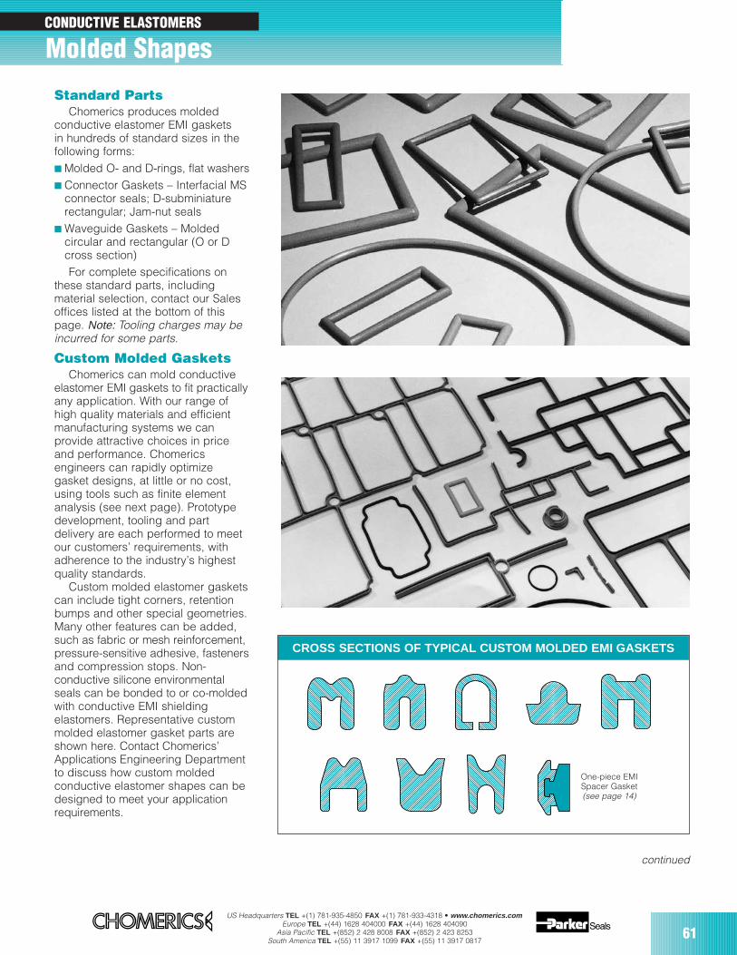
US Headquarters TEL +(1) 781-935-4850 FAX +(1) 781-933-4318 • www.chomerics.comEurope TEL +(44) 1628 404000 FAX +(44) 1628 404090
Asia Pacific TEL +(852) 2 428 8008 FAX +(852) 2 423 8253South America TEL +(55) 11 3917 1099 FAX +(55) 11 3917 0817
61
CROSS SECTIONS OF TYPICAL CUSTOM MOLDED EMI GASKETS
One-piece EMISpacer Gasket(see page 14)
Standard PartsChomerics produces molded
conductive elastomer EMI gasketsin hundreds of standard sizes in thefollowing forms: Molded O- and D-rings, flat washers Connector Gaskets – Interfacial MS
connector seals; D-subminiaturerectangular; Jam-nut seals
Waveguide Gaskets – Moldedcircular and rectangular (O or Dcross section)For complete specifications on
these standard parts, includingmaterial selection, contact our Salesoffices listed at the bottom of thispage. Note: Tooling charges may beincurred for some parts.
Custom Molded GasketsChomerics can mold conductive
elastomer EMI gaskets to fit practicallyany application. With our range ofhigh quality materials and efficientmanufacturing systems we canprovide attractive choices in priceand performance. Chomericsengineers can rapidly optimizegasket designs, at little or no cost,using tools such as finite elementanalysis (see next page). Prototypedevelopment, tooling and partdelivery are each performed to meetour customers’ requirements, withadherence to the industry’s highestquality standards.
Custom molded elastomer gasketscan include tight corners, retentionbumps and other special geometries.Many other features can be added,such as fabric or mesh reinforcement,pressure-sensitive adhesive, fastenersand compression stops. Non-conductive silicone environmentalseals can be bonded to or co-moldedwith conductive EMI shieldingelastomers. Representative custommolded elastomer gasket parts areshown here. Contact Chomerics’Applications Engineering Departmentto discuss how custom moldedconductive elastomer shapes can bedesigned to meet your applicationrequirements.
CONDUCTIVE ELASTOMERS
Molded Shapes
continued
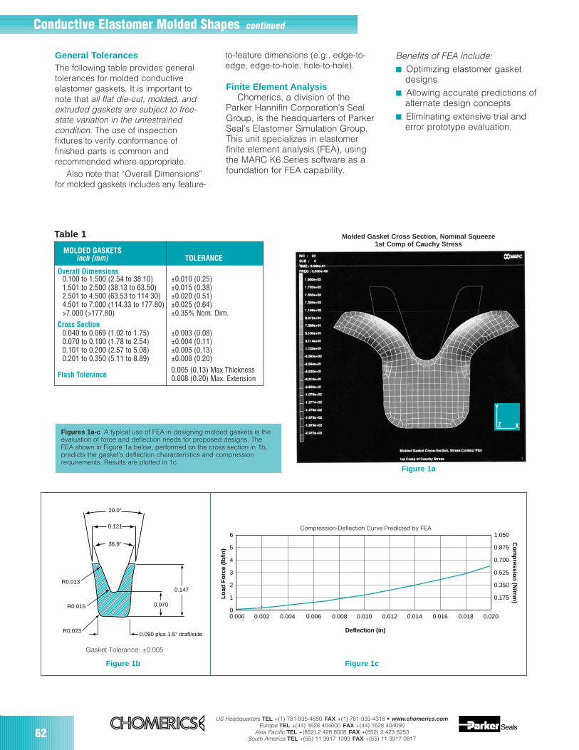
62US Headquarters TEL +(1) 781-935-4850 FAX +(1) 781-933-4318 • www.chomerics.com
Europe TEL +(44) 1628 404000 FAX +(44) 1628 404090Asia Pacific TEL +(852) 2 428 8008 FAX +(852) 2 423 8253
South America TEL +(55) 11 3917 1099 FAX +(55) 11 3917 0817
20.0°
0.121
36.9°
R0.013
R0.015
R0.023
0.070
0.147
0.090 plus 1.5° draft/side
6
5
4
3
2
1
0
1.050
0.875
0.700
0.525
0.350
0.175
0.000 0.002 0.004 0.006 0.008 0.010 0.012 0.014 0.016 0.018 0.020
Compression-Deflection Curve Predicted by FEA
Deflection (in)
Lo
ad F
orc
e (l
b/in
)
Co
mp
ression
(N/m
m)
Gasket Tolerance: ±0.005
Figure 1b Figure 1c
Molded Gasket Cross Section, Nominal Squeeze1st Comp of Cauchy Stress
Y
Z X
Figure 1a
Figures 1a-c A typical use of FEA in designing molded gaskets is theevaluation of force and deflection needs for proposed designs. TheFEA shown in Figure 1a below, performed on the cross section in 1b,predicts the gasket’s deflection characteristics and compressionrequirements. Results are plotted in 1c.
MOLDED GASKETSinch (mm) TOLERANCE
Overall Dimensions0.100 to 1.500 (2.54 to 38.10) ±0.010 (0.25)1.501 to 2.500 (38.13 to 63.50) ±0.015 (0.38)2.501 to 4.500 (63.53 to 114.30) ±0.020 (0.51)4.501 to 7.000 (114.33 to 177.80) ±0.025 (0.64)>7.000 (>177.80) ±0.35% Nom. Dim.
Cross Section0.040 to 0.069 (1.02 to 1.75) ±0.003 (0.08)0.070 to 0.100 (1.78 to 2.54) ±0.004 (0.11)0.101 to 0.200 (2.57 to 5.08) ±0.005 (0.13)0.201 to 0.350 (5.11 to 8.89) ±0.008 (0.20)
Flash Tolerance0.005 (0.13) Max.Thickness0.008 (0.20) Max. Extension
Table 1
General TolerancesThe following table provides generaltolerances for molded conductiveelastomer gaskets. It is important tonote that all flat die-cut, molded, andextruded gaskets are subject to free-state variation in the unrestrainedcondition. The use of inspectionfixtures to verify conformance offinished parts is common andrecommended where appropriate.
Also note that “Overall Dimensions”for molded gaskets includes any feature-
Finite Element AnalysisChomerics, a division of the
Parker Hannifin Corporation’s SealGroup, is the headquarters of ParkerSeal’s Elastomer Simulation Group.This unit specializes in elastomerfinite element analysis (FEA), usingthe MARC K6 Series software as afoundation for FEA capability.
Benefits of FEA include: Optimizing elastomer gasket
designs Allowing accurate predictions of
alternate design concepts Eliminating extensive trial and
error prototype evaluation.
Conductive Elastomer Molded Shapes continued
to-feature dimensions (e.g., edge-to-edge, edge-to-hole, hole-to-hole).
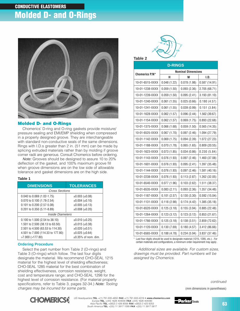
US Headquarters TEL +(1) 781-935-4850 FAX +(1) 781-933-4318 • www.chomerics.comEurope TEL +(44) 1628 404000 FAX +(44) 1628 404090
Asia Pacific TEL +(852) 2 428 8008 FAX +(852) 2 423 8253South America TEL +(55) 11 3917 1099 FAX +(55) 11 3917 0817
63
Molded D- and O-RingsChomerics’ D-ring and O-ring gaskets provide moisture/
pressure sealing and EMI/EMP shielding when compressedin a properly designed groove. They are interchangeablewith standard non-conductive seals of the same dimensions.Rings with I.D.s greater than 2 in. (51 mm) can be made bysplicing extruded materials rather than by molding if groovecorner radii are generous. Consult Chomerics before ordering.
Note: Grooves should be designed to assure 10 to 20%deflection of the gasket, and 100% maximum groove fillwhen groove dimensions are on the low side of allowabletolerance and gasket dimensions are on the high side.
Table 1
Ordering ProcedureSelect the part number from Table 2 (D-rings) and
Table 3 (O-rings) which follow. The last four digitsdesignate the material. We recommend CHO-SEAL 1215material for the highest level of shielding effectiveness;CHO-SEAL 1285 material for the best combination ofshielding effectiveness, corrosion resistance, weight,cost and temperature range; and CHO-SEAL 1298 for thehighest level of corrosion resistance. (For material propertyspecifications, refer to Table 3, pages 32-34.) Note: Toolingcharges may be incurred for some parts.
D-RINGS
Chomerics P/N*Nominal Dimensions
H W I.D.
10-01-6515-XXXX 0.048 (1.22) 0.078 (1.98) 0.587 (14.91)
10-01-1238-XXXX 0.059 (1.50) 0.093 (2.36) 2.705 (68.71)
10-01-1239-XXXX 0.059 (1.50) 0.095 (2.41) 3.193 (81.10)
10-01-1240-XXXX 0.061 (1.55) 0.025 (0.66) 0.180 (4.57)
10-01-1241-XXXX 0.061 (1.55) 0.039 (0.99) 0.151 (3.84)
10-01-1628-XXXX 0.062 (1.57) 0.096 (2.44) 1.562 (39.67)
10-01-1154-XXXX 0.062 (1.57) 0.069 (1.75) 0.893 (22.68)
10-01-1375-XXXX 0.066 (1.68) 0.059 (1.50) 0.565 (14.35)
10-01-6525-XXXX 0.067 (1.70) 0.097 (2.46) 1.094 (27.79)
10-01-1142-XXXX 0.069 (1.75) 0.094 (2.39) 1.072 (27.23)
10-01-1188-XXXX 0.070 (1.78) 0.065 (1.65) 0.809 (20.55)
10-01-1623-XXXX 0.073 (1.85) 0.034 (0.86) 0.230 (5.84)
10-01-1143-XXXX 0.076 (1.93) 0.097 (2.46) 1.460 (37.08)
10-01-1601-XXXX 0.076 (1.93) 0.095 (2.41) 1.397 (35.48)
10-01-1144-XXXX 0.076 (1.93) 0.097 (2.46) 1.581 (40.16)
10-01-2238-XXXX 0.076 (1.93) 0.113 (2.87) 1.262 (32.05)
10-01-6540-XXXX 0.077 (1.96) 0.103 (2.62) 1.511 (38.37)
10-01-6535-XXXX 0.083 (2.11) 0.093 (2.36) 1.357 (34.48)
10-01-1187-XXXX 0.101 (2.57) 0.130 (3.30) 0.592 (15.04)
10-01-1131-XXXX 0.118 (2.98) 0.174 (4.42) 1.385 (35.18)
10-01-6520-XXXX 0.125 (3.18) 0.155 (3.94) 0.885 (22.48)
10-01-1264-XXXX 0.123 (3.12) 0.123 (3.12) 0.853 (21.67)
10-01-1766-XXXX 0.125 (3.18) 0.138 (3.51) 2.859 (72.62)
10-01-1120-XXXX 0.130 (7.69) 0.180 (4.57) 3.412 (86.66)
10-01-6565-XXXX 0.188 (4.78) 0.234 (5.94) 3.837 (37.46)
Table 2
* Last four digits should be used to designate material (1215, 1285, etc.) . Forcertain materials and configurations, a minimum order requirement may apply .
(mm dimensions in parentheses)
I.D. W
H
DIMENSIONS TOLERANCESCross Sections
0.040 to 0.069 (1.02-1.75) ±0.003 (±0.08)0.070 to 0.100 (1.78-2.54) ±0.004 (±0.10)0.101 to 0.200 (2.57-5.08) ±0.005 (±0.13)0.201 to 0.350 (5.11-8.89) ±0.008 (±0.20)
Inside Diameters
0.100 to 1.500 (2.54 to 38.10) ±0.010 (±0.25)1.501 to 2.500 (38.13 to 63.50) ±0.015 (±0.38)2.501 to 4.500 (63.53 to 114.30) ±0.020 (±0.51)4.501 to 7.000 (114.33 to 177.80) ±0.025 (±0.64)>7.000 (>177.80) ±0.35% of nom. dim.
Molded D- and O-Rings CONDUCTIVE ELASTOMERS
continued
Additional sizes are available. For custom sizes,drawings must be provided. Part numbers will beassigned by Chomerics.
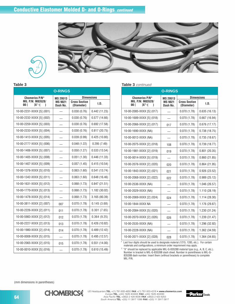
64US Headquarters TEL +(1) 781-935-4850 FAX +(1) 781-933-4318 • www.chomerics.com
Europe TEL +(44) 1628 404000 FAX +(44) 1628 404090Asia Pacific TEL +(852) 2 428 8008 FAX +(852) 2 423 8253
South America TEL +(55) 11 3917 1099 FAX +(55) 11 3917 0817
Table 3 continuedTable 3
O-RINGS
10-00-2232-XXXX [5] (002) –– 0.030 (0.76) 0.577 (14.66)
10-00-2259-XXXX [5] (003) –– 0.030 (0.76) 0.692 (17.58)
–– 0.030 (0.76) 0.442 (11.23)10-00-2231-XXXX [5] (001)
10-00-2233-XXXX [5] (004) –– 0.030 (0.76) 0.817 (20.75)
10-00-1413-XXXX [5] (005) –– 0.039 (0.99) 0.425 (10.80)
10-00-2777-XXXX [5] (006) –– 0.048 (1.22) 0.295 (7.49)
10-00-1406-XXXX [5] (007) –– 0.050 (1.27) 0.533 (13.54)
10-00-1405-XXXX [5] (008) –– 0.051 (1.30) 0.446 (11.33)
10-00-1407-XXXX [5] (009) –– 0.057 (1.45) 0.415 (10.54)
10-00-1376-XXXX [5] (010) –– 0.063 (1.60) 0.541 (13.74)
10-00-1342-XXXX [5] (011) –– 0.063 (1.60) 0.648 (16.46)
10-00-1631-XXXX [5] (012) –– 0.068 (1.73) 0.847 (21.51)
10-00-1770-XXXX [5] (013) –– 0.068 (1.73) 1.182 (30.02)
10-00-1478-XXXX [5] (014) –– 0.068 (1.73) 3.165 (80.39)
10-00-3811-XXXX [2] (007) 007 0.070 (1.78) 0.145 (3.68)
10-00-2226-XXXX [2] (011) 011 0.070 (1.78) 0.301 (7.65)
10-00-5983-XXXX [2] (012) 012 0.070 (1.78) 0.364 (9.25)
10-00-2227-XXXX [2] (013) 013 0.070 (1.78) 0.426 (10.82)
10-00-1980-XXXX [2] (014) 014 0.070 (1.78) 0.489 (12.42)
10-00-0008-XXXX [5] (015) –– 0.070 (1.78) 0.495 (12.57)
10-00-2065-XXXX [2] (015) 015 0.070 (1.78) 0.551 (14.00)
MS 29513MS 9021Dash No.
Chomerics P/N*MIL P/N: M83528/00 [ ]X †-( )
Cross Section(Diameter) I.D.
Dimensions
* Last four digits should be used to designate material (1215, 1285, etc.). For certainmaterials and configurations, a minimum order requirement may apply .
† “X” should be replaced by applicable MIL-G-83528B material type (e.g., A, B, C, etc.).Number in bracket is MIL-G-83528B slash sheet. Number in parentheses is MIL-G-83528B dash number. Insert them (without brackets or parentheses) to completeMIL P/N.
O-RINGS
Chomerics P/N*MIL P/N: M83528/00 [ ]X †-( )
MS 29513MS 9021Dash No.
DimensionsCross Section
(Diameter) I.D.
10-00-2066-XXXX [2] (017) 017 0.070 (1.78) 0.676 (17.17)
10-00-1690-XXXX (NA) –– 0.070 (1.78) 0.738 (18.75)
10-00-0012-XXXX (NA) –– 0.070 (1.78) 0.735 (18.67)
10-00-2075-XXXX [2] (018) 108 0.070 (1.78) 0.739 (18.77)
10-00-1981-XXXX [2] (019) 019 0.070 (1.78) 0.801 (20.35)
10-00-0014-XXXX [5] (019) –– 0.070 (1.78) 0.860 (21.85)
10-00-2076-XXXX [2] (020) 020 0.070 (1.78) 0.864 (21.95)
10-00-1843-XXXX [2] (021) 021 0.070 (1.78) 0.926 (23.52)
10-00-2068-XXXX [2] (022) 022 0.070 (1.78) 0.989 (25.12)
10-00-2536-XXXX (NA) –– 0.070 (1.78) 1.046 (26.57)
10-00-2029-XXXX (NA) –– 0.070 (1.78) 1.110 (28.19)
10-00-2069-XXXX [2] (024) 024 0.070 (1.78) 1.114 (28.30)
10-00-1844-XXXX NA –– 0.070 (1.78) 1.176 (29.87)
10-00-2084-XXXX [5] (020) –– 0.070 (1.78) 1.230 (31.24)
10-00-2070-XXXX [2] (026) 026 0.070 (1.78) 1.239 (31.47)
10-00-2535-XXXX (NA) –– 0.070 (1.78) 1.296 (32.92)
10-00-2228-XXXX (NA) –– 0.070 (1.78) 1.362 (34.59)
10-00-2071-XXXX [2] (028) 028 0.070 (1.78) 1.364 (34.65)
(mm dimensions in parentheses)
10-00-0010-XXXX [5] (016) –– 0.070 (1.78) 0.610 (15.49)
10-00-1689-XXXX [5] (018) –– 0.070 (1.78) 0.667 (16.94)
10-00-2085-XXXX [5] (017) –– 0.070 (1.78) 0.635 (16.13)
Conductive Elastomer Molded D- and O-Rings continued
I.D.
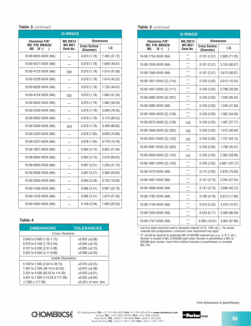
US Headquarters TEL +(1) 781-935-4850 FAX +(1) 781-933-4318 • www.chomerics.comEurope TEL +(44) 1628 404000 FAX +(44) 1628 404090
Asia Pacific TEL +(852) 2 428 8008 FAX +(852) 2 423 8253South America TEL +(55) 11 3917 1099 FAX +(55) 11 3917 0817
65
Table 3 continued Table 3 continued735
(18.67)10-00-2075-XXXX[2] (018)0180.070
(1.78)0.73918.77)10-00-1981-XXXX
[2] (019)0190.070(1.78)0.801
(20.35)10-00-0014-XXXX[5] (019)–
–0.070(1.78)0.860
(21.85)10-00-2076-XXXX[2] (020)0200.070
(1.78)0.864(21.95)10-00-1843-XXXX
[2] ((021)0210.070(1.78)0.926
(23.52)10-00-2068-XXXX[2] (022)0220.070
(1.78)0.989(25.12)10-00-2536-XXXX
(NA)––0.070
(1.78)1.046(26.57)10-00-2090-XXXX
(NA)––0.070
(1.78)1.110(28.19)10-00-2069-XXXX
[2] (024)0240.070(1.78)1.114
(28.30)10-00-1844-XXXX(NA)––0.070
(1.78)1.176(29.87)10-00-2084-XXXX
[5] (020––0.070
(1.78)1.230(31.24)0.070(1.78)1.296
(32.92)10-00-2228-XXXX(NA)––0.070
(1.78)1.362(34.59)10-00-2071-XXXX
[2] (028)0280.070(1.78)1.364
(34.65)O-RINGS (continued)10-00-2677-XXXX(NA)––0.070
O-RINGS
Chomerics P/N*MIL P/N: M83528/00[ ]X †-( )
MS 29513MS 9021Dash No.
Dimensions
Cross Section(Diameter) I.D.
––––
0.101 (2.57) 2.805 (71.25)10-00-1754-XXXX (NA)
10-00-1359-XXXX (NA) ––––
0.101 (2.57) 3.153 (80.87)
10-00-1360-XXXX (NA) ––––
0.101 (2.57) 3.613 (80.87)
10-00-1921-XXXX [2] (114) ––––
0.103 (2.62) 0.612 (15.54)
10-00-1847-XXXX [2] (117) ––––
0.103 (2.62) 0.799 (20.29)
10-00-4685-XXXX [5] (021) ––––
0.103 (2.62) 1.040 (26.42)
10-00-2086-XXXX (NA) ––––
0.103 (2.62) 1.240 (31.50)
10-00-1845-XXXX [2] (126) ––––
0.103 (2.62) 1.362 (34.59)
10-00-2072-XXXX [2] (128) 128 0.103 (2.62) 1.487 (37.77)
10-00-1846-XXXX [5] (022) 130 0.103 (2.62) 1.612 (40.94)
10-00-2031-XXXX [2] (132) 132 0.103 (2.62) 1.737 (44.12)
10-00-2087-XXXX [5] (023) ––––
0.103 (2.62) 1.790 (45.47)
10-00-2030-XXXX [2] (142) 142 0.103 (2.62) 2.362 (59.99)
10-00-1691-XXXX [2] (155) ––––
0.103 (2.62) 3.987 (101.27)
10-00-1573-XXXX (NA) ––––
0.115 (2.92) 2.876 (73.05)
10-00-1607-XXXX (NA) ––––
0.147 (3.73) 2.265 (57.53)
10-00-1608-XXXX (NA) ––––
0.147 (3.73) 3.690 (93.73)
10-00-1782-XXXX (NA) ––––
0.188 (4.78) 0.673 (17.09)
10-00-1746-XXXX (NA) ––––
0.210 (5.33) 3.475 (12.07)
10-00-1354-XXXX (NA) ––––
0.243 (6.17) 3.409 (86.59)
10-00-1747-XXXX (NA) ––––
0.394 (10.01) 3.464 (87.99)
(mm dimensions in parentheses)
* Last four digits should be used to designate material (1215, 1285, etc.). For certainmaterials and configurations, a minimum order requirement may apply .
† “X” should be replaced by applicable MIL-G-83528B material type (e.g., A, B, C, etc.).Number in bracket is MIL-G-83528B slash sheet. Number in parentheses is MIL-G-83528B dash number. Insert them (without brackets or parentheses) to completeMIL P/N.
Table 4
O-RINGS
10-00-2677-XXXX (NA) –– 0.070 (1.78)
Chomerics P/N*MIL P/N: M83528/
00[ ]X †-( )
MS 29513MS 9021Dash No.
Dimensions
1.609 (40.87)
10-00-4123-XXXX (NA) 030
Cross Section(Diameter) I.D.
10-00-0024-XXXX (NA) –– 0.070 (1.78) 1.485 (37.72)
0.070 (1.78) 1.614 (41.00)
10-00-2229-XXXX (NA) –– 0.070 (1.78) 1.674 (42.52)
10-00-0028-XXXX (NA) –– 0.070 (1.78) 1.735 (44.07)
10-00-4124-XXXX (NA) 032 0.070 (1.78) 1.864 (47.35)
10-00-0032-XXXX (NA) –– 0.070 (1.78) 1.980 (50.29)
10-00-2230-XXXX (NA) –– 0.070 (1.78) 3.009 (76.43)
10-00-0052-XXXX (NA) –– 0.070 (1.78) 3.170 (80.52)
10-00-2040-XXXX (NA) 043 0.070 (1.78) 3.489 (88.62)
10-00-2320-XXXX (NA) –– 0.076 (1.93) 0.656 (16.66)
10-00-2321-XXXX (NA) –– 0.076 (1.93) 0.779 (19.79)
10-00-1827-XXXX (NA) –– 0.084 (2.13) 0.852 (21.64)
10-00-0044-XXXX (NA) –– 0.084 (2.13) 2.678 (68.02)
10-00-0020-XXXX (NA) –– 0.087 (2.21) 1.250 (31.75)
10-00-0038-XXXX (NA) –– 0.087 (2.21) 2.360 (59.94)
10-00-3550-XXXX (NA) –– 0.094 (2.39) 0.750 (19.05)
10-00-1459-XXXX (NA) –– 0.095 (2.41) 0.897 (22.78)
10-00-1378-XXXX (NA) –– 0.095 (2.41) 1.074 (27.28)
10-00-4452-XXXX (NA) –– 0.100 (2.54) 1.005 (25.53)
DIMENSIONS TOLERANCESCross Sections
0.040 to 0.069 (1.02-1.75) ±0.003 (±0.08)0.070 to 0.100 (1.78-2.54) ±0.004 (±0.10)0.101 to 0.200 (2.57-5.08) ±0.005 (±0.13)0.201 to 0.350 (5.11-8.89) ±0.008 (±0.20)
Inside Diameters
0.100 to 1.500 (2.54 to 38.10) ±0.010 (±0.25)1.501 to 2.500 (38.13 to 63.50) ±0.015 (±0.38)2.501 to 4.500 (63.53 to 114.30) ±0.020 (±0.51)4.501 to 7.000 (114.33 to 177.80) ±0.025 (±0.64)>7.000 (>177.80) ±0.35% of nom. dim.
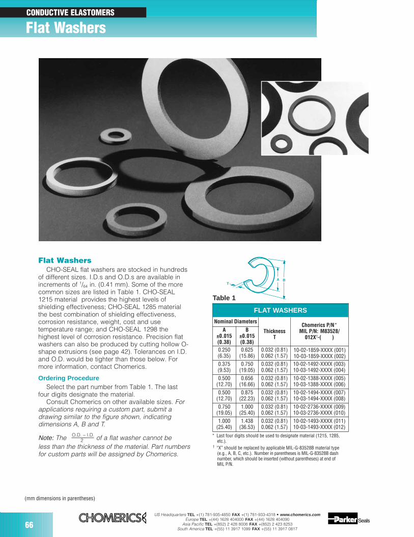
66US Headquarters TEL +(1) 781-935-4850 FAX +(1) 781-933-4318 • www.chomerics.com
Europe TEL +(44) 1628 404000 FAX +(44) 1628 404090Asia Pacific TEL +(852) 2 428 8008 FAX +(852) 2 423 8253
South America TEL +(55) 11 3917 1099 FAX +(55) 11 3917 0817
Flat WashersCHO-SEAL flat washers are stocked in hundreds
of different sizes. I.D.s and O.D.s are available inincrements of 1/64 in. (0.41 mm). Some of the morecommon sizes are listed in Table 1. CHO-SEAL1215 material provides the highest levels ofshielding effectiveness; CHO-SEAL 1285 materialthe best combination of shielding effectiveness,corrosion resistance, weight, cost and usetemperature range; and CHO-SEAL 1298 thehighest level of corrosion resistance. Precision flatwashers can also be produced by cutting hollow O-shape extrusions (see page 42). Tolerances on I.D.and O.D. would be tighter than those below. Formore information, contact Chomerics.
Ordering ProcedureSelect the part number from Table 1. The last
four digits designate the material.Consult Chomerics on other available sizes. For
applications requiring a custom part, submit adrawing similar to the figure shown, indicatingdimensions A, B and T.
Note: The O.D. – I.D. of a flat washer cannot be2less than the thickness of the material. Part numbersfor custom parts will be assigned by Chomerics.
Nominal Diameters
ThicknessChomerics P/N*
MIL P/N: M83528/012X†-( )
B±0.015(0.38)
0.250(6.35)
0.625(15.86)
0.032 (0.81)0.062 (1.57)
0.375(9.53)
0.750(19.05)
0.032 (0.81)0.062 (1.57)
10-02-1492-XXXX (003)10-03-1492-XXXX (004)
0.500(12.70)
0.656(16.66)
0.032 (0.81)0.062 (1.57)
10-02-1388-XXXX (005)10-03-1388-XXXX (006)
0.500(12.70)
0.875(22.23)
0.032 (0.81)0.062 (1.57)
10-02-1494-XXXX (007)10-03-1494-XXXX (008)
0.750(19.05)
1.000(25.40)
0.032 (0.81)0.062 (1.57)
10-02-2736-XXXX (009)10-03-2736-XXXX (010)
1.000(25.40)
1.438(36.53)
0.032 (0.81)0.062 (1.57)
10-02-1493-XXXX (011)10-03-1493-XXXX (012)
A±0.015(0.38)
10-02-1859-XXXX (001)10-03-1859-XXXX (002)
* Last four digits should be used to designate material (1215, 1285,etc.).
† “X” should be replaced by applicable MIL-G-83528B material type(e.g., A, B, C, etc.). Number in parentheses is MIL-G-83528B dashnumber, which should be inserted (without parentheses) at end ofMIL P/N.
FLAT WASHERS
Table 1
A B
T
(mm dimensions in parentheses)
Flat WashersCONDUCTIVE ELASTOMERS
T
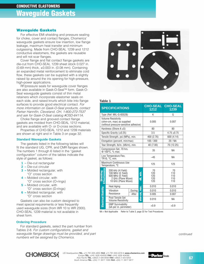
US Headquarters TEL +(1) 781-935-4850 FAX +(1) 781-933-4318 • www.chomerics.comEurope TEL +(44) 1628 404000 FAX +(44) 1628 404090
Asia Pacific TEL +(852) 2 428 8008 FAX +(852) 2 423 8253South America TEL +(55) 11 3917 1099 FAX +(55) 11 3917 0817
67
NA = Not Applicable Refer to T able 3, page 32 for Test Procedures
Waveguide GasketsFor effective EMI shielding and pressure sealing
for choke, cover and contact flanges, Chomerics’waveguide gaskets ensure low insertion, low flangeleakage, maximum heat transfer and minimumoutgassing. Made from CHO-SEAL 1239 and 1212conductive elastomers, the gaskets are reusableand will not scar flanges.
Cover flange and flat contact flange gaskets aredie-cut from CHO-SEAL 1239 sheet stock 0.027 in.(0.69 mm) thick, ±0.003 in. (0.08 mm). Containingan expanded metal reinforcement to eliminate coldflow, these gaskets can be supplied with a slightlyraised lip around the iris opening for high-pressure,high-power applications.
RF/pressure seals for waveguide cover flangesare also available in Gask-O-SealTM form. Gask-O-Seal waveguide gaskets consist of thin metalretainers which incorporate elastomer seals oneach side, and raised knurls which bite into flangesurfaces to provide good electrical contact. Formore information on Gask-O-Seal products, contactParker Hannifin, Cleveland, OH, 1-800-272-7537and ask for Gask-O-Seal catalog #OSD-6411A.
Choke flange and grooved contact flangegaskets are molded from CHO-SEAL 1212 material,and are available with O- or D-cross sections.
Properties of CHO-SEAL 1212 and 1239 materialsare shown at right and in Table 3 on page 32.
Standard Waveguide GasketsThe gaskets listed in the following tables will
fit the standard UG, CPR, and CMR flanges shown.The numbers 1 through 6 listed in the “gasketconfiguration” column of the tables indicate thestyle of gasket, as follows:
1 – Die-cut rectangular2 – Die-cut circular3 – Molded rectangular, with
“O” cross section4 – Molded circular, with
“O” cross section (O-rings)5 – Molded circular, with
“D” cross section (D-rings)6 – Molded rectangular, with
“D” cross sectionGaskets can also be custom designed to
meet special requirements or less frequentlyused waveguide sizes (from WR 10 to WR 2300).CHO-SEAL 1239 material is not available insheet form.
SPECIFICATIONSCHO-SEAL
1212CHO-SEAL
1239
Type (Ref: MIL-G-83528) K G
0.005 0.007
Hardness (Shore A ±5) 80 80
Specific Gravity (±0.25) 3.5 4.75 ±0.75Tensile Strength, psi (MPa), min. 400 (2.76) 600 (4.14)
Volume Resistivity(ohm-cm, max) as supplied(without pressure-sensitive adhesive)
Elongation (percent, min/max) 100 / 300 20 / NA
Tear Strength, lb/in. (kN/m), min. 40 (7.00) 70 (12.25)
Compression Set, 70 hrs.@ 100°C, % max. 35 NA
Low Temperature Flex, TR10, °C, min. –45 NA
Maximum Continuous UseTemperature, °C 125 125
70110110110110
200 kHz (H Field)100 MHz (E Field)500 MHz (E Field)
2 GHz (Plane Wave)10 GHz (Plane Wave)
70120120120120
Heat Aging 0.010 0.010
0.010 NAPost Tensile SetVolume ResistivityEMP Survivability(kA per in. perimeter) >0.9 >0.9
VibrationResistance
0.0100.005
0.0100.007
DuringAfter
ohm
-cm
, max
.dB
, min
.
Shie
ldin
gEf
fect
iven
ess
Elec
tric
al S
tabi
lity
Ordering ProcedureFor standard gaskets, select the part number from
Tables 2-8. For custom configurations, gasket andwaveguide flange drawings must be provided, and partnumbers will be assigned by Chomerics.
Table 1
Waveguide GasketsCONDUCTIVE ELASTOMERS
continued

68US Headquarters TEL +(1) 781-935-4850 FAX +(1) 781-933-4318 • www.chomerics.com
Europe TEL +(44) 1628 404000 FAX +(44) 1628 404090Asia Pacific TEL +(852) 2 428 8008 FAX +(852) 2 423 8253
South America TEL +(55) 11 3917 1099 FAX +(55) 11 3917 0817
Table 2
FrequencyRange(GHz)
Band
26.5 40.0 Ka WR28
EIAWaveguide
Size
RG-96/U(Silver)
JANDesignation
UG-599/U
UG-600A/U
Flange Description
Cover
Choke
FlangeType
1
5
GasketConfiguration*
20-01-5000-1239**
20-02-6510-1212
ChomericsPart Number
[G]-(001)
[K]-(002)
MIL P/N:†
M83528/013 [ ]-( )
18.0 26.5 K WR42
RG-53/U(Brass)
UG-595/UUG-597/U Cover 1 20-01-5005-1239** [G]-(003)
12.4 18.0 Ku WR62
RG-91/U(Brass) UG-419/U Cover 1 20-01-5010-1239** [G]-(005)
RG-121/U(Aluminum)
UG-596A/UUG-598A/U Choke 5 20-02-6515-1212 [K]-(004)
RG-107/U(Silver) Choke 5 20-02-6520-1212 [K]-(006)UG-541A/U
10.0 15.0 WR75 CoverChoke
15
20-11-1683-123920-02-6525-1212
[G]-(007)[K]-(008)
8.2 12.4 X WR90
RG-52/U(Brass)
RG-67/U(Aluminum)
UG-39/UUG-135/U Cover 1 20-11-5015-1239 [G]-(009)
CPR-90F FlatContact 1 20-01-5115-1239** [G]-(010)
UG-136A/UUG-40A/U Choke 5 20-02-6531-1212 [K]-(011)
UG-136B/UUG-40B/U Choke 5 20-02-6530-1212 [K]-(012)
UG-1360/UUG-1361/U Contact 3 20-03-6630-1212 [K]-(013)CPR-90G
UG-1736/UUG-1737/U
7.0 11.0 WR102 UG-1494/U Choke 5 20-02-6535-1212 [K]-(014)
7.05 10.0 X1 WR112
RG-51/U(Brass)
RG-68/U(Aluminum)
UG-51/UUG-138/U Cover 1 20-11-5020-1239 [G]-(015)
CPR-112F 1 20-01-5120-1239** [G]-(016)
UG-52B/UUG-137B/U Choke 5 20-02-6540-1212 [K]-(017)
UG-1358/UUG-1359/U
CPR-112GCPR-112G/F
ContactChoke/Flat
36
20-03-6635-121220-03-3686-1212
[K]-(018)––
UG-1734/UUG-1735/U
Flat Contact
5.85 8.2 Xb WR137
RG-50/U(Brass)
RG-106/U(Aluminum)
UG-344/UUG-441/U Cover 2 20-11-5025-1239 [G]-(019)
UG-1732/UUG-1733/U CPR-137F Flat
Contact 1 20-01-5125-1239** [G]-(020)
FlatContact 1 [G]-(021)
UG-343B/UUG-440B/U Choke 4 20-02-6545-1212 [K]-(022)
UG-1356/UUG-1357/U
CPR-137GCPR-137G/F
ContactChoke/Flat
36
20-03-6645-121220-03-3731-1212
[K]-(023)––
CMR-137 20-01-5225-1239**
4.9 7.05 WR159
UG-1730/UUG-1731/U CPR-159F Flat
Contact 1 20-01-5130-1239** [G]-(024)
CMR-159 FlatContact 1 20-01-5230-1239** [G]-(025)
WAVEGUIDE GASKETS
* Number corresponds to configuration type, Tables 3-8.** This gasket will seal a maximum pressure of 20 psi. For systems pressurized above
this limit, a high-pressure (raised-lip) version is available. T o specify, change 3rd digitin Part Number to 1.
UG CPR CMR
CPR-159G Choke 3 20-03-L767-1212 ––
CPR-159G/F Choke/Flat 6 20-03-3980-1212 ––
Use Table 2 to select part numbers. Refer to Tables 3-8 on following pages for Waveguide Gasket dimensions.
† Letter in bracket is MIL-G-83528B material type (G or K). Number in parenthesesis MIL-G-83528B dash number. Insert them (without brackets or parentheses) tocomplete MIL P/N.
(mm dimensions in parentheses)
Conductive Elastomer Waveguide Gaskets continued
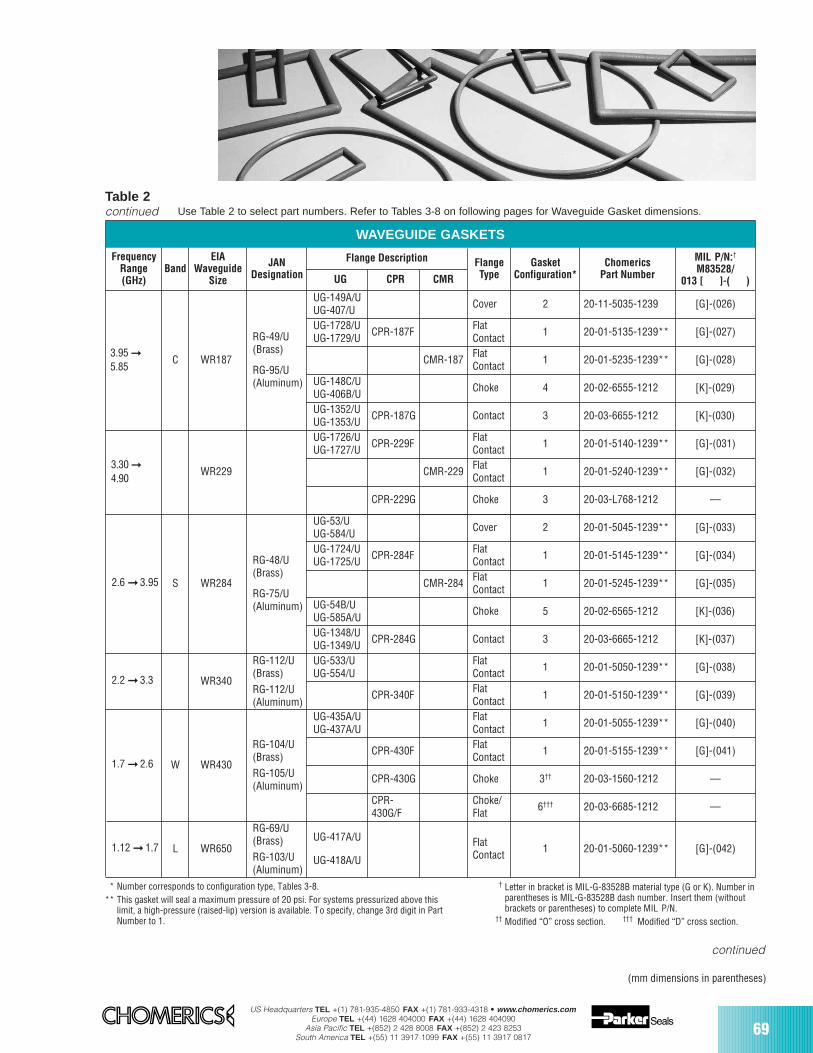
US Headquarters TEL +(1) 781-935-4850 FAX +(1) 781-933-4318 • www.chomerics.comEurope TEL +(44) 1628 404000 FAX +(44) 1628 404090
Asia Pacific TEL +(852) 2 428 8008 FAX +(852) 2 423 8253South America TEL +(55) 11 3917 1099 FAX +(55) 11 3917 0817
69
* Number corresponds to configuration type, Tables 3-8.** This gasket will seal a maximum pressure of 20 psi. For systems pressurized above this
limit, a high-pressure (raised-lip) version is available. To specify, change 3rd digit in PartNumber to 1.
† Letter in bracket is MIL-G-83528B material type (G or K). Number inparentheses is MIL-G-83528B dash number. Insert them (withoutbrackets or parentheses) to complete MIL P/N.
†† Modified “O” cross section. ††† Modified “D” cross section.
Table 2continued
FrequencyRange(GHz)
BandEIA
WaveguideSize
JANDesignation
Flange Description FlangeType
GasketConfiguration*
ChomericsPart Number
MIL P/N:†
M83528/013 [ ]-( )
UG-1352/UUG-1353/U CPR-187G Contact 3 20-03-6655-1212 [K]-(030)
C WR187
RG-49/U(Brass)
RG-95/U(Aluminum)
UG-149A/UUG-407/U Cover 2
UG-1728/UUG-1729/U CPR-187F Flat
Contact 1 20-01-5135-1239** [G]-(027)
CMR-187 FlatContact 1 20-01-5235-1239** [G]-(028)
UG-148C/UUG-406B/U Choke 4 20-02-6555-1212 [K]-(029)
WAVEGUIDE GASKETS
3.30
4.90WR229
UG-1726/UUG-1727/U CPR-229F Flat
Contact 1 20-01-5140-1239** [G]-(031)
CMR-229 FlatContact 1 20-01-5240-1239** [G]-(032)
2.6 3.95 S WR284
RG-48/U(Brass)
RG-75/U(Aluminum)
UG-53/UUG-584/U Cover 2 20-01-5045-1239** [G]-(033)
UG-1724/UUG-1725/U CPR-284F Flat
Contact 1 20-01-5145-1239** [G]-(034)
CMR-284 FlatContact 1 20-01-5245-1239** [G]-(035)
UG-54B/UUG-585A/U Choke 5 20-02-6565-1212 [K]-(036)
UG-1348/UUG-1349/U CPR-284G Contact 3 20-03-6665-1212 [K]-(037)
2.2 3.3 WR340
RG-112/U(Brass)RG-112/U(Aluminum)
UG-533/UUG-554/U
FlatContact 1 20-01-5050-1239** [G]-(038)
CPR-340F FlatContact 1 20-01-5150-1239** [G]-(039)
1.7 2.6 W WR430
RG-104/U(Brass)RG-105/U(Aluminum)
UG-435A/UUG-437A/U
FlatContact 1 20-01-5055-1239** [G]-(040)
CPR-430F FlatContact 1 20-01-5155-1239** [G]-(041)
L WR650
RG-69/U(Brass)RG-103/U(Aluminum)
UG-417A/U
UG-418A/U
FlatContact 1 20-01-5060-1239** [G]-(042)
UG CPR CMR
1.12 1.7
3.95
5.85
CPR-229G Choke 3 20-03-L768-1212 ––
20-11-5035-1239 [G]-(026)
CPR-430G Choke 3†† 20-03-1560-1212 ––
CPR-430G/F
Choke/Flat 6††† 20-03-6685-1212 ––
Use Table 2 to select part numbers. Refer to Tables 3-8 on following pages for Waveguide Gasket dimensions.
(mm dimensions in parentheses)
continued
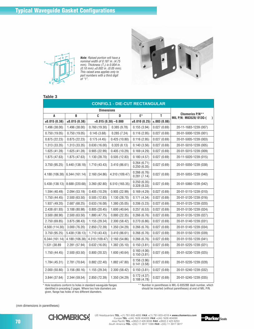
70US Headquarters TEL +(1) 781-935-4850 FAX +(1) 781-933-4318 • www.chomerics.com
Europe TEL +(44) 1628 404000 FAX +(44) 1628 404090Asia Pacific TEL +(852) 2 428 8008 FAX +(852) 2 423 8253
South America TEL +(55) 11 3917 1099 FAX +(55) 11 3917 0817
Table 3
CONFIG.1 - DIE-CUT RECTANGULAR
A B C E* T
±0.015 (0.38) ±0.015 (0.38) +0.015 (0.38) –0.000 ±0.010 (0.25) ±.003 (0.08)
1.496 (38.00) 1.496 (38.00) 0.760 (19.30) 0.385 (9.78) 0.155 (3.94) 0.027 (0.69) 20-11-1683-1239 (007)
0.750 (19.05) 0.750 (19.05) 0.145 (3.68) 0.285 (7.24) 0.116 (2.95) 0.027 (0.69) 20-01-5000-1239 (001)
0.875 (22.23) 0.875 (22.23) 0.175 (4.45) 0.425 (10.80) 0.116 (2.95) 0.027 (0.69) 20-01-5005-1239 (003)
1.313 (33.35) 1.313 (33.35) 0.630 (16.00) 0.320 (8.13) 0.140 (3.56) 0.027 (0.69) 20-01-5010-1239 (005)
1.625 (41.28) 1.625 (41.28) 0.905 (22.99) 0.405 (10.29) 0.169 (4.29) 0.027 (0.69) 20-01-5015-1239 (009)
1.875 (47.63) 1.875 (47.63) 1.130 (28.70) 0.505 (12.83) 0.180 (4.57) 0.027 (0.69) 20-11-5020-1239 (015)
3.750 (95.25) 5.440 (138.18) 1.710 (43.43) 3.410 (86.61) 0.264 (6.71)0.250 (6.35) 0.027 (0.69) 20-01-5050-1239 (038)
4.188 (106.38) 6.344 (161.14) 2.160 (54.86) 4.310 (109.47) 0.027 (0.69) 20-01-5055-1239 (040)
5.438 (138.13) 8.688 (220.68) 3.260 (82.80) 6.510 (165.35) 0.027 (0.69) 20-01-5060-1239 (042)
1.594 (40.49) 2.094 (53.19) 0.405 (10.29) 0.905 (22.99) 0.169 (4.29) 0.027 (0.69) 20-01-5115-1239 (010)
1.750 (44.45) 2.500 (63.50) 0.505 (12.83) 1.130 (28.70) 0.171 (4.34) 0.027 (0.69) 20-01-5120-1239 (016)
1.937 (49.20) 2.687 (68.25) 0.633 (16.08) 1.380 (35.05) 0.206 (5.23) 0.027 (0.69) 20-01-5125-1239 (020)
2.438 (61.93) 3.188 (80.98) 0.805 (20.45) 1.600 (40.64) 0.257 (6.53) 0.027 (0.69) 20-01-5130-1239 (024)
3.500 (88.90) 2.500 (63.50) 1.880 (47.75) 0.880 (22.35) 0.266 (6.76) 0.027 (0.69) 20-01-5135-1239 (027)
2.750 (69.85) 3.875 (98.43) 1.155 (29.34) 2.300 (58.42) 0.270 (6.86) 0.027 (0.69) 20-01-5140-1239 (031)
4.500 (114.30) 3.000 (76.20) 2.850 (72.39) 1.350 (34.29) 0.266 (6.76) 0.027 (0.69) 20-01-5145-1239 (034)
3.750 (95.25) 5.438 (138.13) 1.710 (43.43) 3.410 (86.61) 0.266 (6.76) 0.027 (0.69) 20-01-5150-1239 (039)
6.344 (161.14) 4.188 (106.38) 2.160 (54.86) 0.266 (6.76) 0.027 (0.69) 20-01-5155-1239 (041)
0.266 (6.76)0.281 (7.14)
0.250 (6.35)0.328 (8.33)
DimensionsChomerics P/N**
MIL P/N: M83528/ 013G-( )
* Hole locations conform to holes in standard waveguide flangesidentified in preceding 2 pages. Where two hole diameters aregiven, flange has holes of two different diameters.
(mm dimensions in parentheses)
Note: Raised portion will have anominal width of 0.187 in. (4.75mm). Thickness (T1) is 0.004 in.(0.10 mm) ±0.002 in. (0.05 mm).This raised area applies only topart numbers with a third digitof “1”.
D
1.531 (38.89 2.281 (57.94) 0.632 (16.05) 1.382 (35.10) 0.150 (3.81) 0.027 (0.69) 20-01-5225-1239 (021)
1.750 (44.45) 2.500 (63.50) 0.800 (20.32) 1.600 (40.64) 0.160 (4.06)0.150 (3.81) 0.027 (0.69) 20-01-5230-1239 (025)
1.784 (45.31) 2.781 (70.64) 0.882 (22.40) 1.882 (47.80) 0.156 (3.96)0.141 (3.58) 0.027 (0.69) 20-01-5235-1239 (028)
2.000 (50.80) 3.156 (80.16) 1.155 (29.34) 2.300 (58.42) 0.150 (3.81) 0.027 (0.69) 20-01-5240-1239 (032)
3.844 (37.64) 2.344 (59.54) 2.850 (72.39) 1.350 (34.29) 0.172 (4.37)0.188 (4.78) 0.027 (0.69) 20-01-5245-1239 (035)
4.310 (109.47)
** Number in parentheses is MIL-G-83528B dash number, whichshould be inserted (without parentheses) at end of MIL P/N.
Typical Waveguide Gasket Configurations
DB
E T1
T
CA
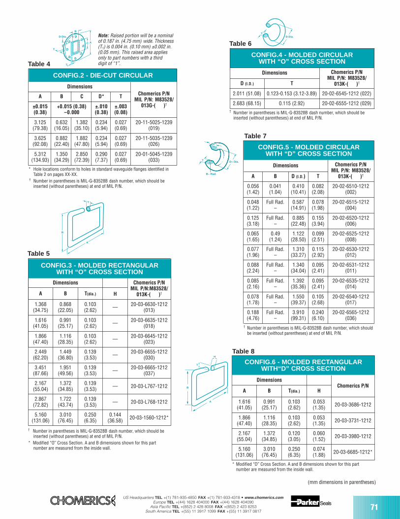
US Headquarters TEL +(1) 781-935-4850 FAX +(1) 781-933-4318 • www.chomerics.comEurope TEL +(44) 1628 404000 FAX +(44) 1628 404090
Asia Pacific TEL +(852) 2 428 8008 FAX +(852) 2 423 8253South America TEL +(55) 11 3917 1099 FAX +(55) 11 3917 0817
71
(mm dimensions in parentheses)
Table 6
Table 7
CONFIG.4 - MOLDED CIRCULARWITH “O” CROSS SECTION
Dimensions Chomerics P/NMIL P/N: M83528/
013K-( )†D (I.D.) T
2.011 (51.08) 0.123-0.153 (3.12-3.89) 20-02-6545-1212 (022)
2.683 (68.15) 0.115 (2.92) 20-02-6555-1212 (029)
CONFIG.5 - MOLDED CIRCULARWITH “D” CROSS SECTION
Dimensions Chomerics P/NMIL P/N: M83528/
013K-( )†A B D (I.D.) T
0.056(1.42)
0.041(1.04)
0.410(10.41)
0.082(2.08)
20-02-6510-1212(002)
0.048(1.22)
Full Rad.–
0.587(14.91)
0.078(1.98)
20-02-6515-1212(004)
0.125(3.18)
Full Rad.–
0.885(22.48)
0.155(3.94)
20-02-6520-1212(006)
0.065(1.65)
0.49(1.24)
1.122(28.50)
0.099(2.51)
20-02-6525-1212(008)
0.077(1.96)
Full Rad.–
1.310(33.27)
0.115(2.92)
20-02-6530-1212(012)
0.088(2.24)
Full Rad.–
1.340(34.04)
0.095(2.41)
20-02-6531-1212(011)
0.085(2.16)
Full Rad.–
1.392(35.36)
0.095(2.41)
20-02-6535-1212(014)
0.078(1.78)
Full Rad.–
1.550(39.37)
0.105(2.68)
20-02-6540-1212(017)
0.188(4.76)
Full Rad.–
3.910(99.31)
0.240(6.10)
20-02-6565-1212(036)
* Hole locations conform to holes in standard waveguide flanges identified inTable 2 on pages XX-XX.
† Number in parentheses is MIL-G-83528B dash number, which should beinserted (without parentheses) at end of MIL P/N.
Note: Raised portion will be a nominalof 0.187 in. (4.75 mm) wide. Thickness(T1) is 0.004 in. (0.10 mm) ±0.002 in.(0.05 mm). This raised area appliesonly to part numbers with a thirddigit of “1”.
CONFIG.2 - DIE-CUT CIRCULAR
DimensionsChomerics P/N
MIL P/N: M83528/013G-( )†
A B D* T
±0.015(0.38)
+0.015 (0.38)–0.000
±.010(0.38)
±.003(0.08)
3.125(79.38)
0.632(16.05)
1.382(35.10)
0.234(5.94)
0.027(0.69)
20-11-5025-1239(019)
3.625(92.08)
0.882(22.40)
1.882(47.80)
0.234(5.94)
0.027(0.69)
20-11-5035-1239(026)
5.312(134.93)
1.350(34.29)
2.850(72.39)
0.290(7.37)
0.027(0.69)
20-01-5045-1239(033)
C
Table 5
Dimensions
A B T(dia.)
1.368(34.75)
0.868(22.05)
0.103(2.62)
1.616(41.05)
0.991(25.17)
0.103(2.62) ––
1.866(47.40)
1.116(28.35)
0.103(2.62) ––
2.449(62.20)
1.449(36.80)
0.139(3.53) ––
3.451(87.66)
1.951(49.56)
0.139(3.53) ––
––
2.167(55.04)
1.372(34.85)
0.139(3.53) ––
5.160(131.06)
3.010(76.45)
2.867(72.82)
1.722(43.74)
0.139(3.53) ––
0.250(6.35)
0.144(36.58)
Chomerics P/NMIL P/N:M83528/
013K-( )†
20-03-6630-1212(013)
20-03-6635-1212(018)
20-03-6645-1212(023)
20-03-6655-1212(030)
20-03-6665-1212(037)
20-03-L767-1212
20-03-L768-1212
20-03-1560-1212*
H
Dimensions
2.167(55.04)
A B T(dia.)
1.372(34.85)
1.616(41.05)
0.991(25.17)
0.103(2.62)
0.053(1.35)
1.866(47.40)
1.116(28.35)
0.103(2.62)
0.053(1.35)
0.120(3.05)
0.060(1.52)
5.160(131.06)
3.010(76.45)
0.250(6.35)
0.074(1.88)
Chomerics P/N
20-03-3686-1212
20-03-3731-1212
20-03-3980-1212
20-03-6685-1212*
H
CONFIG.3 - MOLDED RECTANGULARWITH “O” CROSS SECTION
CONFIG.6 - MOLDED RECTANGULAR WITH“D” CROSS SECTION
† Number in parentheses is MIL-G-83528B dash number, which should beinserted (without parentheses) at end of MIL P/N.
* Modified “O” Cross Section. A and B dimensions shown for this partnumber are measured from the inside wall.
Table 8
* Modified “D” Cross Section. A and B dimensions shown for this partnumber are measured from the inside wall.
Table 4
† Number in parentheses is MIL-G-83528B dash number, which should beinserted (without parentheses) at end of MIL P/N.
† Number in parentheses is MIL-G-83528B dash number, which shouldbe inserted (without parentheses) at end of MIL P/N.
D-Dia.
T
C A
B
D-Dia.
T1
T
T
B
A
H
T
B
A
D– Dia.T
B– Rad.
A
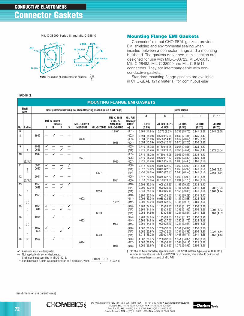
72US Headquarters TEL +(1) 781-935-4850 FAX +(1) 781-933-4318 • www.chomerics.com
Europe TEL +(44) 1628 404000 FAX +(44) 1628 404090Asia Pacific TEL +(852) 2 428 8008 FAX +(852) 2 423 8253
South America TEL +(55) 11 3917 1099 FAX +(55) 11 3917 0817
Connector Gaskets CONDUCTIVE ELASTOMERS
Mounting Flange EMI GasketsChomerics’ die-cut CHO-SEAL gaskets provide
EMI shielding and environmental sealing wheninserted between a connector flange and a mountingbulkhead. The gaskets described in this section aredesigned for use with MIL-C-83723, MIL-C-5015,MIL-C-26482, MIL-C-38999 and MIL-C-81511 connectors. They are interchangeable with non-conductive gaskets.
Standard mounting flange gaskets are availablein CHO-SEAL 1212 material, for continuous-use
Table 1
MIL-C-38999 Series III and MIL-C-28840
MOUNTING FLANGE EMI GASKETS
ShellSize
Configuration Drawing No. (See Ordering Procedure on Next Page) Dimensions
MIL-C-28840
MIL-C-5015C-83723
NAS-1599MIL-C-26482
MIL P/N:M83528/
004X†
–( )
A B C D E***MIL-C-38999
MIL-C-81511MS90484
±0.010(0.25)
+0.020 (0.51)-0.000
±0.015(0.38)
±0.010(0.25)
±0.010(0.25)No. Letter
SeriesI II III IV
6 1946* (001) 0.469 (11.91) 0.375 (9.53) 0.738 (18.75) 0.141 (3.58) 0.141 (3.58)8 1947 –– –– ––
46901948
(002)(003)(004)
0.594 (15.09)0.594 (15.09)0.594 (15.09)
0.630 (16.00)0.568 (14.43)0.500 (12.70)
0.840 (21.34)0.812 (20.62)0.875 (22.23)
0.135 (3.43)0.125 (3.18)0.156 (3.96)
9A
1949C646
––
––
––––
(005)(NA)
0.719 (18.26)0.719 (18.26)
0.750 (19.05)0.750 (19.05)
0.965 (24.51)0.965 (24.51)
0.135 (3.43)0.135 (3.43)
–––– 0.222 (5.64)
10
(S/SL)
1949 –– –– ––4691
1950
(005)(006)(007)
0.135 (3.43)0.125 (3.18)0.156 (3.96)
0.719 (18.26)0.719 (18.26)0.719 (18.26)
0.750 (19.05)0.680 (17.27)0.625 (15.88)
0.965 (24.51)0.937 (23.80)1.000 (25.40)
11BA
6961C647
––
––––
––
––
C637
(008)(NA)(NA)
0.812 (20.62)0.812 (20.62)0.750 (19.05)
0.875 (22.23)0.875 (22.23)0.875 (22.23)
1.060 (26.92)1.060 (26.92)1.046 (26.57)
0.141 (3.58)0.141 (3.58)0.141 (3.58)
0.206 (5.23)0.163 (4.14)
12(S/SL)
6961 –– –– ––1951
(008)(009)
0.812 (20.62)0.813 (20.65)
0.875 (22.23)0.750 (19.05)
1.060 (26.92)1.094 (27.79)
0.141 (3.58)0.156 (3.96)
13CB
1953C648
––
––––
––
C638
(010)(NA)(NA)
0.906 (23.01)0.906 (23.01)0.843 (21.41)
1.005 (25.53)1.000 (25.40)1.000 (25.40)
1.153 (29.29)1.156 (29.36)1.156 (29.36)
0.135 (3.43)0.141 (3.58)0.141 (3.58)
0.206 (5.23)0.167 (4.24)
14
(S)
1953 –– –– ––4692
1952
(010)(011)(012)
1.005 (25.53)0.938 (23.83)0.875 (22.23)
0.135 (3.43)0.125 (3.18)0.156 (3.96)
0.906 (23.01)0.906 (23.01)0.906 (23.01)
15DC
1955C649
––
––––
––
––
C639
(013)(NA)(NA)
0.969 (24.61)0.969 (24.61)0.968 (24.59)
1.135 (28.83)1.135 (28.83)1.187 (30.15)
1.258 (31.95)1.258 (31.95)1.281 (32.54)
0.156 (3.96)0.156 (3.96)0.141 (3.58)
0.206 (5.23)0.161 (4.09)
16
(S)
1955 –– –– ––4693
1954
(013)(014)(015)
0.969 (24.61)0.969 (24.61)0.969 (24.61)
1.135 (28.83)1.063 (27.00)1.000 (25.40)
1.258 (31.95)1.250 (31.75)1.281 (32.54)
0.156 (3.96)0.125 (3.18)0.156 (3.96)
17ED
1957C650
––
––––
––
C640
(016)(NA)(NA)
1.062 (26.97)1.062 (26.97)1.015 (25.78)
1.351 (34.32)1.351 (34.32)1.406 (35.71)
0.156 (3.96)0.156 (3.96)0.141 (3.58)
0.222 (5.64)0.163 (4.14)
1.260 (32.00)1.260 (32.00)1.250 (31.75)
18 (S) 1957 –– –– ––4694
1956
(016)(017)(018)
1.062 (26.97)1.062 (26.97)1.062 (26.97)
1.260 (32.00)1.189 (30.20)1.135 (28.83)
1.351 (34.32)1.343 (34.11)1.375 (34.93)
0.156 (3.96)0.125 (3.18)0.156 (3.96)
1.153 (29.29)1.125 (28.58)1.188 (30.18)
Available in series designated.–– Not applicable in series designated.* Shell size 6 not specified in MIL-C-5015.*** For dimension E, hole is slotted through to B diameter , when
(1.41xA) – D –B≤ .032 in.
2
† “X” should be replaced by applicable MIL-G-83528B material type (e.g. A, B, C, etc.).Number in parentheses is MIL-G-83528B dash number, which should be inserted(without parentheses) at end of MIL P/N.
Note: The radius of each corner is equal to C-A2
A C
A
.032
D–Dia.
B–Dia.
A Ref.
C Ref.
B Dia. Ref.E***
D
Full Radius
(mm dimensions in parentheses)
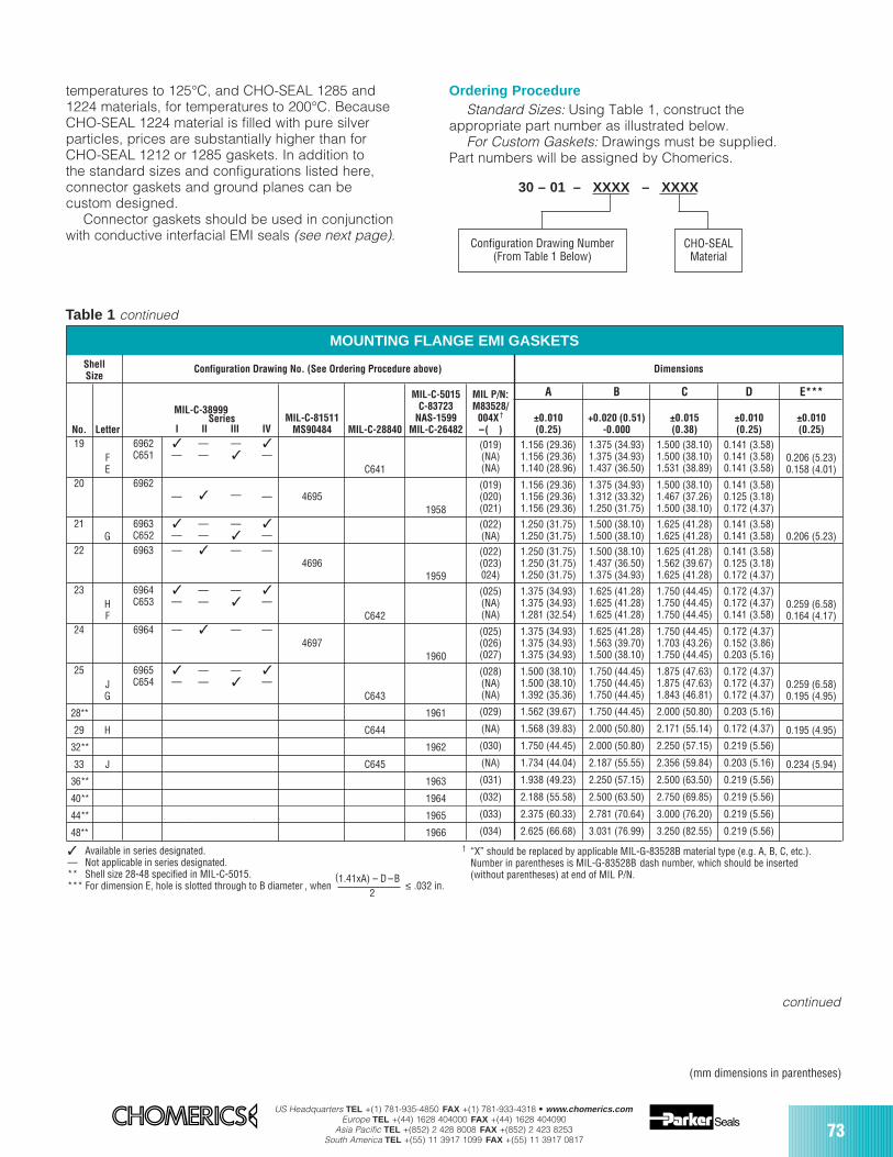
US Headquarters TEL +(1) 781-935-4850 FAX +(1) 781-933-4318 • www.chomerics.comEurope TEL +(44) 1628 404000 FAX +(44) 1628 404090
Asia Pacific TEL +(852) 2 428 8008 FAX +(852) 2 423 8253South America TEL +(55) 11 3917 1099 FAX +(55) 11 3917 0817
73
temperatures to 125°C, and CHO-SEAL 1285 and1224 materials, for temperatures to 200°C. BecauseCHO-SEAL 1224 material is filled with pure silverparticles, prices are substantially higher than forCHO-SEAL 1212 or 1285 gaskets. In addition tothe standard sizes and configurations listed here,connector gaskets and ground planes can becustom designed.
Connector gaskets should be used in conjunctionwith conductive interfacial EMI seals (see next page).
Ordering ProcedureStandard Sizes: Using Table 1, construct the
appropriate part number as illustrated below.For Custom Gaskets: Drawings must be supplied.
Part numbers will be assigned by Chomerics.
MOUNTING FLANGE EMI GASKETS
ShellSize
Configuration Drawing No. (See Ordering Procedure above) Dimensions
MIL-C-28840
MIL-C-5015C-83723
NAS-1599MIL-C-26482
MIL P/N:M83528/
004X†
–( )
A B C D E***
MIL-C-38999MIL-C-81511
MS90484±0.010(0.25)
+0.020 (0.51)-0.000
±0.015(0.38)
±0.010(0.25)
±0.010(0.25)No. Letter
SeriesI II III IV
19FE
6962C651
––
––––
––
––
C641
(019)(NA)(NA)
1.156 (29.36)1.156 (29.36)1.140 (28.96)
1.375 (34.93)1.375 (34.93)1.437 (36.50)
1.500 (38.10)1.500 (38.10)1.531 (38.89)
0.141 (3.58)0.141 (3.58)0.141 (3.58)
0.206 (5.23)0.158 (4.01)
20 6962–– –– –– 4695
1958
(019)(020)(021)
1.156 (29.36)1.156 (29.36)1.156 (29.36)
1.375 (34.93)1.312 (33.32)1.250 (31.75)
1.500 (38.10)1.467 (37.26)1.500 (38.10)
0.141 (3.58)0.125 (3.18)0.172 (4.37)
21G
6963C652
––
––––
––
(022)(NA)
1.250 (31.75)1.250 (31.75)
1.500 (38.10)1.500 (38.10)
1.625 (41.28)1.625 (41.28)
0.141 (3.58)0.141 (3.58) 0.206 (5.23)
22 6963 –– –– ––4696
1959
(022)(023)024)
1.250 (31.75)1.250 (31.75)1.250 (31.75)
1.500 (38.10)1.437 (36.50)1.375 (34.93)
1.625 (41.28)1.562 (39.67)1.625 (41.28)
0.141 (3.58)0.125 (3.18)0.172 (4.37)
23HF
6964C653
––
––––
––
––
C642
(025)(NA)(NA)
1.375 (34.93)1.375 (34.93)1.281 (32.54)
1.625 (41.28)1.625 (41.28)1.625 (41.28)
1.750 (44.45)1.750 (44.45)1.750 (44.45)
0.172 (4.37)0.172 (4.37)0.141 (3.58)
0.259 (6.58)0.164 (4.17)
24 6964 –– –– ––4697
1960
(025)(026)(027)
1.375 (34.93)1.375 (34.93)1.375 (34.93)
1.625 (41.28)1.563 (39.70)1.500 (38.10)
1.750 (44.45)1.703 (43.26)1.750 (44.45)
0.172 (4.37)0.152 (3.86)0.203 (5.16)
25JG
6965C654
––
––––
––
––
C643
(028)(NA)(NA)
1.500 (38.10)1.500 (38.10)1.392 (35.36)
1.750 (44.45)1.750 (44.45)1.750 (44.45)
1.875 (47.63)1.875 (47.63)1.843 (46.81)
0.172 (4.37)0.172 (4.37)0.172 (4.37)
0.259 (6.58)0.195 (4.95)
28** 1961 (029) 1.562 (39.67) 1.750 (44.45) 2.000 (50.80) 0.203 (5.16)
29 H C644 (NA) 1.568 (39.83) 2.000 (50.80) 2.171 (55.14) 0.172 (4.37) 0.195 (4.95)
32** 1962 (030) 1.750 (44.45) 2.000 (50.80) 2.250 (57.15) 0.219 (5.56)
33 J C645 (NA) 1.734 (44.04) 2.187 (55.55) 2.356 (59.84) 0.203 (5.16) 0.234 (5.94)
36** 1963 (031) 1.938 (49.23) 2.250 (57.15) 2.500 (63.50) 0.219 (5.56)
40** 1964 (032) 2.188 (55.58) 2.500 (63.50) 2.750 (69.85) 0.219 (5.56)
48** 1966 (034) 2.625 (66.68) 3.031 (76.99) 3.250 (82.55) 0.219 (5.56)
† “X” should be replaced by applicable MIL-G-83528B material type (e.g. A, B, C, etc.). Number in parentheses is MIL-G-83528B dash number, which should be inserted(without parentheses) at end of MIL P/N.
30 – 01 – XXXX – XXXX
Configuration Drawing Number(From Table 1 Below)
CHO-SEALMaterial
Table 1 continued
––
44** 1965 (033) 2.375 (60.33) 2.781 (70.64) 3.000 (76.20) 0.219 (5.56)
continued
(mm dimensions in parentheses)
Available in series designated.–– Not applicable in series designated.** Shell size 28-48 specified in MIL-C-5015.*** For dimension E, hole is slotted through to B diameter , when
(1.41xA) – D –B≤ .032 in.
2
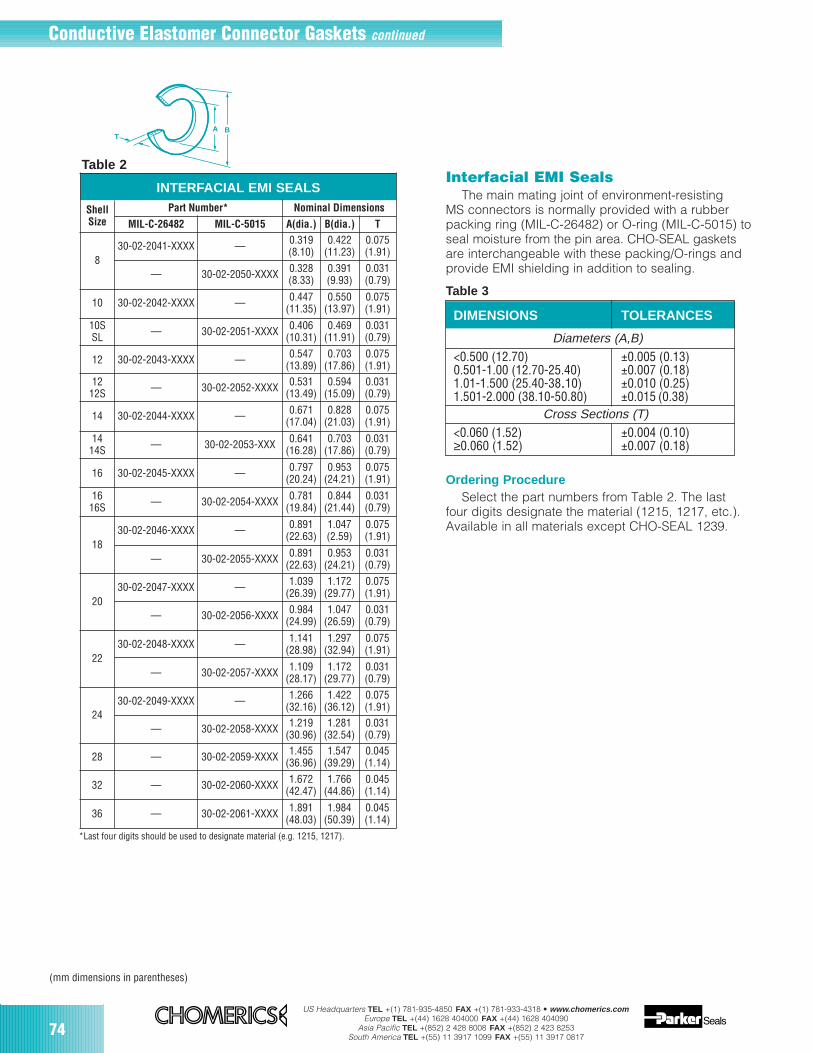
74US Headquarters TEL +(1) 781-935-4850 FAX +(1) 781-933-4318 • www.chomerics.com
Europe TEL +(44) 1628 404000 FAX +(44) 1628 404090Asia Pacific TEL +(852) 2 428 8008 FAX +(852) 2 423 8253
South America TEL +(55) 11 3917 1099 FAX +(55) 11 3917 0817
INTERFACIAL EMI SEALS
ShellSize
Part Number* Nominal Dimensions
MIL-C-26482 MIL-C-5015 A(dia.) B(dia.) T
830-02-2041-XXXX — 0.319
(8.10)0.422
(11.23)0.075(1.91)
— 30-02-2050-XXXX 0.328(8.33)
0.391(9.93)
0.031(0.79)
10 30-02-2042-XXXX — 0.447(11.35)
0.550(13.97)
0.075(1.91)
10SSL — 30-02-2051-XXXX 0.406
(10.31)0.469
(11.91)0.031(0.79)
12 30-02-2043-XXXX — 0.547(13.89)
0.703(17.86)
0.075(1.91)
1212S — 30-02-2052-XXXX 0.531
(13.49)0.594
(15.09)0.031(0.79)
14 30-02-2044-XXXX — 0.671(17.04)
0.828(21.03)
0.075(1.91)
1414S — 30-02-2053-XXX 0.641
(16.28)0.703
(17.86)0.031(0.79)
16 30-02-2045-XXXX — 0.797(20.24)
0.953(24.21)
0.075(1.91)
1616S — 30-02-2054-XXXX 0.781
(19.84)0.844
(21.44)0.031(0.79)
1830-02-2046-XXXX — 0.891
(22.63)1.047(2.59)
0.075(1.91)
— 30-02-2055-XXXX 0.891(22.63)
0.953(24.21)
0.031(0.79)
2030-02-2047-XXXX — 1.039
(26.39)1.172
(29.77)0.075(1.91)
— 30-02-2056-XXXX 0.984(24.99)
1.047(26.59)
0.031(0.79)
2230-02-2048-XXXX — 1.141
(28.98)1.297
(32.94)0.075(1.91)
— 30-02-2057-XXXX 1.109(28.17)
1.172(29.77)
0.031(0.79)
2430-02-2049-XXXX — 1.266
(32.16)1.422
(36.12)0.075(1.91)
— 30-02-2058-XXXX 1.219(30.96)
1.281(32.54)
0.031(0.79)
28 — 30-02-2059-XXXX 1.455(36.96)
1.547(39.29)
0.045(1.14)
32 — 30-02-2060-XXXX 1.672(42.47)
1.766(44.86)
0.045(1.14)
36 — 30-02-2061-XXXX 1.891(48.03)
1.984(50.39)
0.045(1.14)
*Last four digits should be used to designate material (e.g. 1215, 1217).
Interfacial EMI SealsThe main mating joint of environment-resisting
MS connectors is normally provided with a rubberpacking ring (MIL-C-26482) or O-ring (MIL-C-5015) toseal moisture from the pin area. CHO-SEAL gasketsare interchangeable with these packing/O-rings andprovide EMI shielding in addition to sealing.
Table 3
Ordering ProcedureSelect the part numbers from Table 2. The last
four digits designate the material (1215, 1217, etc.).Available in all materials except CHO-SEAL 1239.
Table 2
A B
T
DIMENSIONS TOLERANCES
Diameters (A,B)<0.500 (12.70) ±0.005 (0.13)0.501-1.00 (12.70-25.40) ±0.007 (0.18)1.01-1.500 (25.40-38..10) ±0.010 (0.25)1.501-2.000 (38.10-50.80) ±0.015 (0.38)
Cross Sections (T)<0.060 (1.52) ±0.004 (0.10)≥0.060 (1.52) ±0.007 (0.18)
(mm dimensions in parentheses)
Conductive Elastomer Connector Gaskets continued
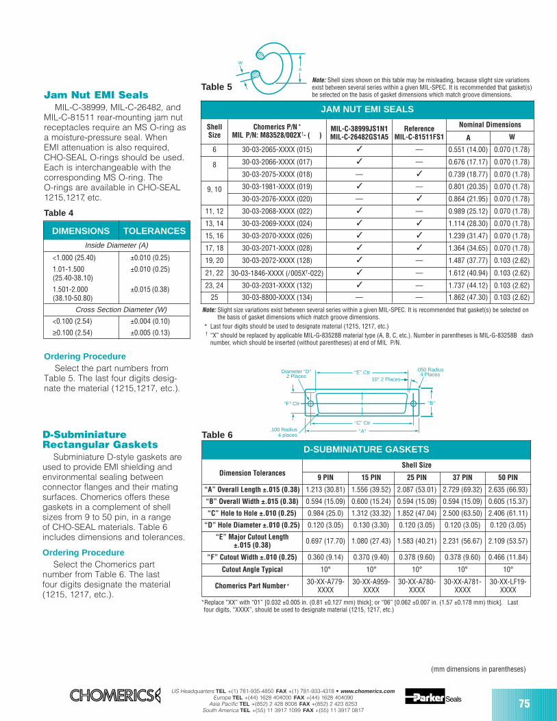
US Headquarters TEL +(1) 781-935-4850 FAX +(1) 781-933-4318 • www.chomerics.comEurope TEL +(44) 1628 404000 FAX +(44) 1628 404090
Asia Pacific TEL +(852) 2 428 8008 FAX +(852) 2 423 8253South America TEL +(55) 11 3917 1099 FAX +(55) 11 3917 0817
75
Jam Nut EMI SealsMIL-C-38999, MIL-C-26482, and
MIL-C-81511 rear-mounting jam nutreceptacles require an MS O-ring asa moisture-pressure seal. WhenEMI attenuation is also required,CHO-SEAL O-rings should be used.Each is interchangeable with thecorresponding MS O-ring. TheO-rings are available in CHO-SEAL1215,1217, etc.
Table 4
Ordering ProcedureSelect the part numbers from
Table 5. The last four digits desig-nate the material (1215,1217, etc.).
Chomerics P/N*MIL P/N: M83528/002X†- ( )
Nominal Dimensions
A W
0.551 (14.00) 0.070 (1.78)
30-03-2066-XXXX (017) 0.676 (17.17) 0.070 (1.78)
0.739 (18.77) 0.070 (1.78)
30-03-1981-XXXX (019) 0.801 (20.35) 0.070 (1.78)
— 0.864 (21.95) 0.070 (1.78)
30-03-2068-XXXX (022) 0.989 (25.12) 0.070 (1.78)
1.114 (28.30) 0.070 (1.78)
30-03-2070-XXXX (026) 1.239 (31.47) 0.070 (1.78)
30-03-2071-XXXX (028) 1.364 (34.65) 0.070 (1.78)
30-03-2072-XXXX (128) 1.487 (37.77) 0.103 (2.62)
30-03-1846-XXXX (/005X†-022) 1.612 (40.94) 0.103 (2.62)
30-03-2031-XXXX (132) 1.737 (44.12) 0.103 (2.62)
Note: Slight size variations exist between several series within a given MIL-SPEC. It is recommended that gasket(s) be selected onthe basis of gasket dimensions which match groove dimensions.
* Last four digits should be used to designate material (1215, 1217, etc.)† “X” should be replaced by applicable MIL-G-83528B material type (A, B, C, etc.). Number in parentheses is MIL-G-83258B dash
number, which should be inserted (without parentheses) at end of MIL P/N.
Table 5
MIL-C-38999JS1N1MIL-C-26482GS1A5
ReferenceMIL-C-81511FS1
—
—
—
—
—
—
—
30-03-2065-XXXX (015)
30-03-2075-XXXX (018)
30-03-2076-XXXX (020)
30-03-2069-XXXX (024)
—
DIMENSIONS TOLERANCES
Inside Diameter (A)
<1.000 (25.40) ±0.010 (0.25)
1.01-1.500 ±0.010 (0.25)(25.40-38..10)
1.501-2.000 ±0.015 (0.38)(38.10-50.80)
Cross Section Diameter (W)
<0.100 (2.54) ±0.004 (0.10)
≥0.100 (2.54) ±0.005 (0.13)
—30-03-8800-XXXX (134) — 1.862 (47.30) 0.103 (2.62)
9 PIN 15 PIN 25 PIN 37 PIN 50 PIN
1.213 (30.81) 1.556 (39.52) 2.087 (53.01) 2.729 (69.32) 2.635 (66.93)
0.594 (15.09) 0.600 (15.24) 0.594 (15.09) 0.594 (15.09) 0.605 (15.37)
0.984 (25.0) 1.312 (33.32) 1.852 (47.04) 2.500 (63.50) 2.406 (61.11)
0.120 (3.05) 0.130 (3.30) 0.120 (3.05) 0.120 (3.05) 0.120 (3.05)
0.697 (17.70) 1.080 (27.43) 1.583 (40.21) 2.231 (56.67) 2.109 (53.57)
0.360 (9.14) 0.370 (9.40) 0.378 (9.60) 0.378 (9.60) 0.466 (11.84)
10° 10° 10° 10° 10°
30-XX-A779-XXXX
30-XX-A959-XXXX
30-XX-A780-XXXX
30-XX-A781-XXXX
30-XX-LF19-XXXX
“A” Overall Length ±.015 (0.38)
“B” Overall Width ±.015 (0.38)
“C” Hole to Hole ±.010 (0.25)
“D” Hole Diameter ±.010 (0.25)
“E” Major Cutout Length±.015 (0.38)
“F” Cutout Width ±.010 (0.25)
Cutout Angle Typical
Chomerics Part Number*
D-SUBMINIATURE GASKETS
Table 6
Shell SizeDimension Tolerances
Diameter “D”2 Places
“F” Ctr
.100 Radius4 places
“E” Ctr
“C” Ctr
.050 Radius4 Places
“B”
“A”
10° 2 Places
*Replace “XX” with “01” [0.032 ±0.005 in. (0.81 ±0.127 mm) thick]; or “06” [0.062 ±0.007 in. (1.57 ±0.178 mm) thick]. Lastfour digits, “XXXX”, should be used to designate material (1215, 1217, etc.)
A
W
ShellSize
25
6
8
9, 10
11, 12
13, 14
15, 16
17, 18
19, 20
21, 22
23, 24
JAM NUT EMI SEALS
Note: Shell sizes shown on this table may be misleading, because slight size variationsexist between several series within a given MIL-SPEC. It is recommended that gasket(s)be selected on the basis of gasket dimensions which match groove dimensions.
D-SubminiatureRectangular Gaskets
Subminiature D-style gaskets areused to provide EMI shielding andenvironmental sealing betweenconnector flanges and their matingsurfaces. Chomerics offers thesegaskets in a complement of shellsizes from 9 to 50 pin, in a rangeof CHO-SEAL materials. Table 6includes dimensions and tolerances.
Ordering ProcedureSelect the Chomerics part
number from Table 6. The lastfour digits designate the material(1215, 1217, etc.).
(mm dimensions in parentheses)
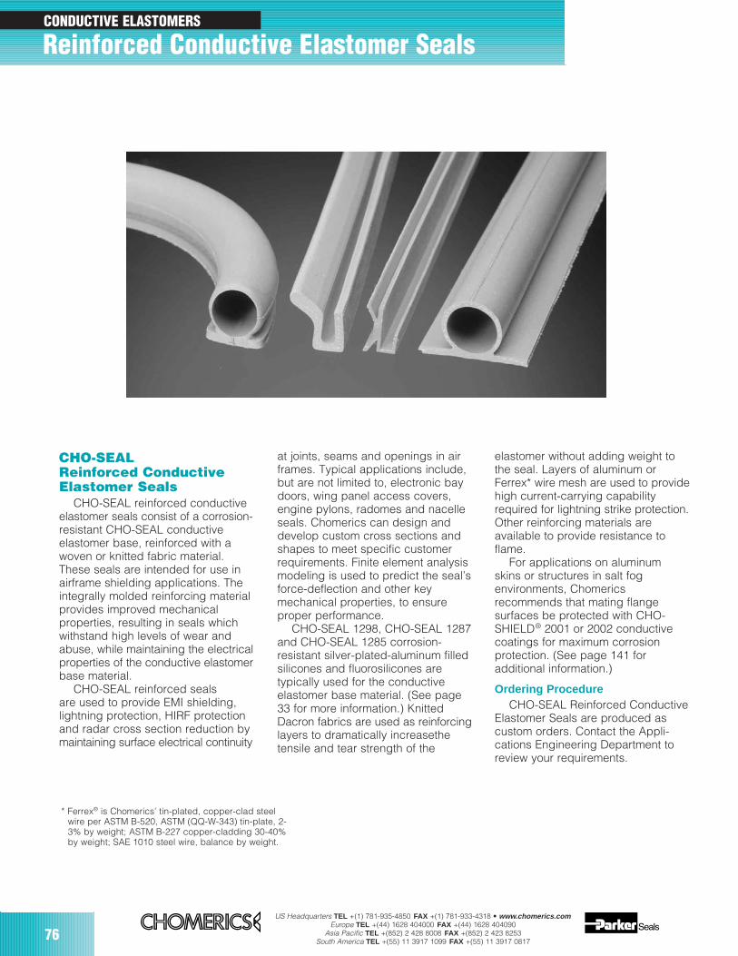
76US Headquarters TEL +(1) 781-935-4850 FAX +(1) 781-933-4318 • www.chomerics.com
Europe TEL +(44) 1628 404000 FAX +(44) 1628 404090Asia Pacific TEL +(852) 2 428 8008 FAX +(852) 2 423 8253
South America TEL +(55) 11 3917 1099 FAX +(55) 11 3917 0817
CONDUCTIVE ELASTOMERS
CHO-SEALReinforced ConductiveElastomer Seals
CHO-SEAL reinforced conductiveelastomer seals consist of a corrosion-resistant CHO-SEAL conductiveelastomer base, reinforced with awoven or knitted fabric material.These seals are intended for use inairframe shielding applications. Theintegrally molded reinforcing materialprovides improved mechanicalproperties, resulting in seals whichwithstand high levels of wear andabuse, while maintaining the electricalproperties of the conductive elastomerbase material.
CHO-SEAL reinforced sealsare used to provide EMI shielding,lightning protection, HIRF protectionand radar cross section reduction bymaintaining surface electrical continuity
at joints, seams and openings in airframes. Typical applications include,but are not limited to, electronic baydoors, wing panel access covers,engine pylons, radomes and nacelleseals. Chomerics can design anddevelop custom cross sections andshapes to meet specific customerrequirements. Finite element analysismodeling is used to predict the seal’sforce-deflection and other keymechanical properties, to ensureproper performance.
CHO-SEAL 1298, CHO-SEAL 1287and CHO-SEAL 1285 corrosion-resistant silver-plated-aluminum filledsilicones and fluorosilicones aretypically used for the conductiveelastomer base material. (See page33 for more information.) KnittedDacron fabrics are used as reinforcinglayers to dramatically increasethetensile and tear strength of the
elastomer without adding weight tothe seal. Layers of aluminum orFerrex* wire mesh are used to providehigh current-carrying capabilityrequired for lightning strike protection.Other reinforcing materials areavailable to provide resistance toflame.
For applications on aluminumskins or structures in salt fogenvironments, Chomericsrecommends that mating flangesurfaces be protected with CHO-SHIELD® 2001 or 2002 conductivecoatings for maximum corrosionprotection. (See page 141 foradditional information.)
Ordering ProcedureCHO-SEAL Reinforced Conductive
Elastomer Seals are produced ascustom orders. Contact the Appli-cations Engineering Department toreview your requirements.
* Ferrex® is Chomerics’ tin-plated, copper-clad steelwire per ASTM B-520, ASTM (QQ-W-343) tin-plate, 2-3% by weight; ASTM B-227 copper-cladding 30-40%by weight; SAE 1010 steel wire, balance by weight.
Reinforced Conductive Elastomer Seals
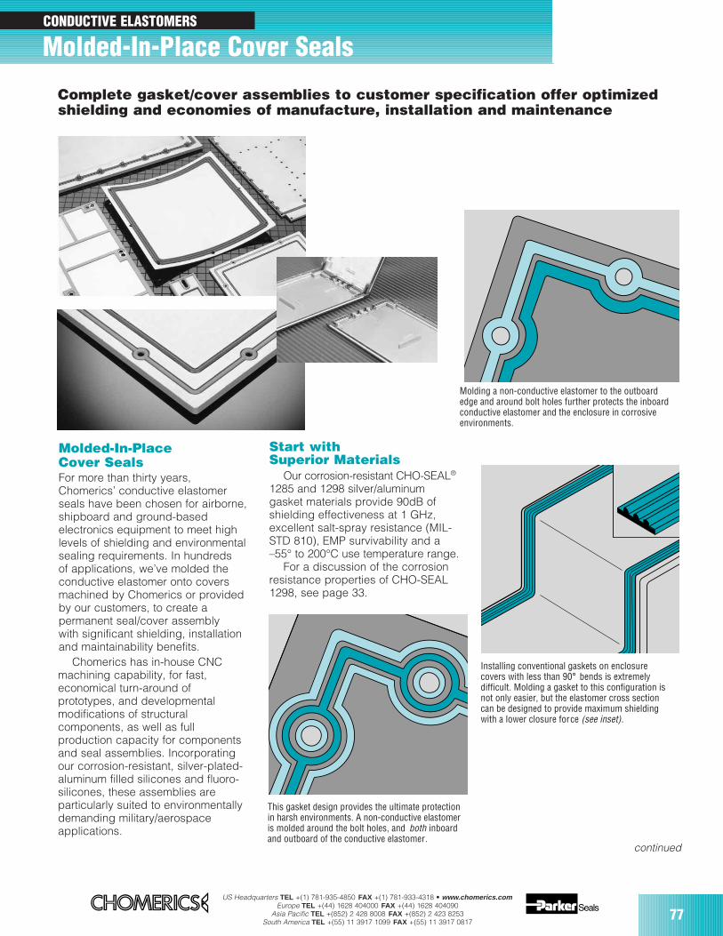
US Headquarters TEL +(1) 781-935-4850 FAX +(1) 781-933-4318 • www.chomerics.comEurope TEL +(44) 1628 404000 FAX +(44) 1628 404090
Asia Pacific TEL +(852) 2 428 8008 FAX +(852) 2 423 8253South America TEL +(55) 11 3917 1099 FAX +(55) 11 3917 0817
77
CONDUCTIVE ELASTOMERS
Start withSuperior Materials
Our corrosion-resistant CHO-SEAL®
1285 and 1298 silver/aluminumgasket materials provide 90dB ofshielding effectiveness at 1 GHz,excellent salt-spray resistance (MIL-STD 810), EMP survivability and a–55° to 200°C use temperature range.
For a discussion of the corrosionresistance properties of CHO-SEAL1298, see page 33.
Molded-In-PlaceCover Seals For more than thirty years,Chomerics’ conductive elastomerseals have been chosen for airborne,shipboard and ground-basedelectronics equipment to meet highlevels of shielding and environmentalsealing requirements. In hundredsof applications, we’ve molded theconductive elastomer onto coversmachined by Chomerics or providedby our customers, to create apermanent seal/cover assemblywith significant shielding, installationand maintainability benefits.
Chomerics has in-house CNCmachining capability, for fast,economical turn-around ofprototypes, and developmentalmodifications of structuralcomponents, as well as fullproduction capacity for componentsand seal assemblies. Incorporatingour corrosion-resistant, silver-plated-aluminum filled silicones and fluoro-silicones, these assemblies areparticularly suited to environmentallydemanding military/aerospaceapplications.
Molding a non-conductive elastomer to the outboardedge and around bolt holes further protects the inboardconductive elastomer and the enclosure in corrosiveenvironments.
Installing conventional gaskets on enclosurecovers with less than 90° bends is extremelydifficult. Molding a gasket to this configuration isnot only easier, but the elastomer cross sectioncan be designed to provide maximum shieldingwith a lower closure force (see inset).
This gasket design provides the ultimate protectionin harsh environments. A non-conductive elastomeris molded around the bolt holes, and both inboardand outboard of the conductive elastomer.
Complete gasket/cover assemblies to customer specification offer optimizedshielding and economies of manufacture, installation and maintenance
Molded-In-Place Cover Seals
continued
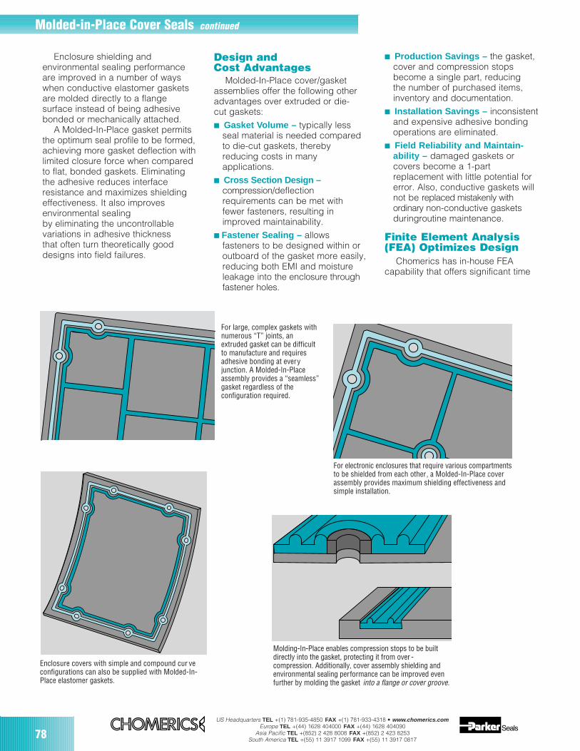
78US Headquarters TEL +(1) 781-935-4850 FAX +(1) 781-933-4318 • www.chomerics.com
Europe TEL +(44) 1628 404000 FAX +(44) 1628 404090Asia Pacific TEL +(852) 2 428 8008 FAX +(852) 2 423 8253
South America TEL +(55) 11 3917 1099 FAX +(55) 11 3917 0817
Design andCost Advantages
Molded-In-Place cover/gasketassemblies offer the following otheradvantages over extruded or die-cut gaskets: Gasket Volume – typically less
seal material is needed comparedto die-cut gaskets, therebyreducing costs in manyapplications.
Cross Section Design –compression/deflectionrequirements can be met withfewer fasteners, resulting inimproved maintainability.
Fastener Sealing – allowsfasteners to be designed within oroutboard of the gasket more easily,reducing both EMI and moistureleakage into the enclosure throughfastener holes.
Production Savings – the gasket,cover and compression stopsbecome a single part, reducingthe number of purchased items,inventory and documentation.
Installation Savings – inconsistentand expensive adhesive bondingoperations are eliminated.
Field Reliability and Maintain-ability – damaged gaskets orcovers become a 1-partreplacement with little potential forerror. Also, conductive gaskets willnot be replaced mistakenly withordinary non-conductive gasketsduringroutine maintenance.
Finite Element Analysis(FEA) Optimizes Design
Chomerics has in-house FEAcapability that offers significant time
Enclosure shielding andenvironmental sealing performanceare improved in a number of wayswhen conductive elastomer gasketsare molded directly to a flangesurface instead of being adhesivebonded or mechanically attached.
A Molded-In-Place gasket permitsthe optimum seal profile to be formed,achieving more gasket deflection withlimited closure force when comparedto flat, bonded gaskets. Eliminatingthe adhesive reduces interfaceresistance and maximizes shieldingeffectiveness. It also improvesenvironmental sealingby eliminating the uncontrollablevariations in adhesive thicknessthat often turn theoretically gooddesigns into field failures.
Enclosure covers with simple and compound cur veconfigurations can also be supplied with Molded-In-Place elastomer gaskets.
For electronic enclosures that require various compartmentsto be shielded from each other, a Molded-In-Place coverassembly provides maximum shielding effectiveness andsimple installation.
Molding-In-Place enables compression stops to be builtdirectly into the gasket, protecting it from over -compression. Additionally, cover assembly shielding andenvironmental sealing performance can be improved evenfurther by molding the gasket into a flange or cover groove.
For large, complex gaskets withnumerous “T” joints, anextruded gasket can be difficultto manufacture and requiresadhesive bonding at everyjunction. A Molded-In-Placeassembly provides a “seamless”gasket regardless of theconfiguration required.
Molded-in-Place Cover Seals continued
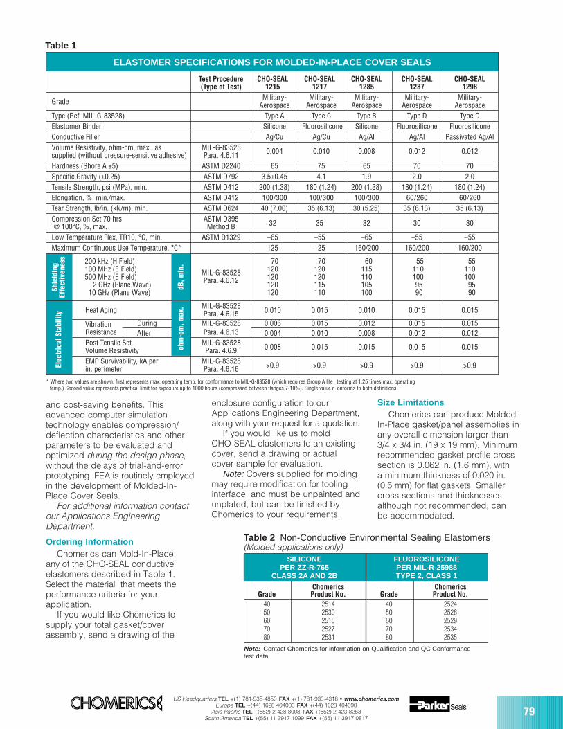
US Headquarters TEL +(1) 781-935-4850 FAX +(1) 781-933-4318 • www.chomerics.comEurope TEL +(44) 1628 404000 FAX +(44) 1628 404090
Asia Pacific TEL +(852) 2 428 8008 FAX +(852) 2 423 8253South America TEL +(55) 11 3917 1099 FAX +(55) 11 3917 0817
79
Size LimitationsChomerics can produce Molded-
In-Place gasket/panel assemblies inany overall dimension larger than3/4 x 3/4 in. (19 x 19 mm). Minimumrecommended gasket profile crosssection is 0.062 in. (1.6 mm), witha minimum thickness of 0.020 in.(0.5 mm) for flat gaskets. Smallercross sections and thicknesses,although not recommended, canbe accommodated.
enclosure configuration to ourApplications Engineering Department,along with your request for a quotation.
If you would like us to moldCHO-SEAL elastomers to an existingcover, send a drawing or actualcover sample for evaluation.
Note: Covers supplied for moldingmay require modification for toolinginterface, and must be unpainted andunplated, but can be finished byChomerics to your requirements.
and cost-saving benefits. Thisadvanced computer simulationtechnology enables compression/deflection characteristics and otherparameters to be evaluated andoptimized during the design phase,without the delays of trial-and-errorprototyping. FEA is routinely employedin the development of Molded-In-Place Cover Seals.
For additional information contactour Applications EngineeringDepartment.
Ordering InformationChomerics can Mold-In-Place
any of the CHO-SEAL conductiveelastomers described in Table 1.Select the material that meets theperformance criteria for yourapplication.
If you would like Chomerics tosupply your total gasket/coverassembly, send a drawing of the
SILICONE FLUOROSILICONEPER ZZ-R-765 PER MIL-R-25988
CLASS 2A AND 2B TYPE 2, CLASS 1
Chomerics ChomericsGrade Product No. Grade Product No.
40 2514 40 252450 2530 50 252660 2515 60 252970 2527 70 253480 2531 80 2535
Table 2 Non-Conductive Environmental Sealing Elastomers(Molded applications only)
* Where two values are shown, first represents max. operating temp. for conformance to MIL-G-83528 (which requires Group A life testing at 1.25 times max. operatingtemp.) Second value represents practical limit for exposure up to 1000 hours (compressed between flanges 7-10%). Single value c onforms to both definitions.
Note: Contact Chomerics for information on Qualification and QC Conformancetest data.
Table 1
ELASTOMER SPECIFICATIONS FOR MOLDED-IN-PLACE COVER SEALS
Test Procedure CHO-SEAL CHO-SEAL CHO-SEAL CHO-SEAL CHO-SEAL(Type of Test) 1215 1217 1285 1287 1298
Grade Military- Military- Military- Military- Military-Aerospace Aerospace Aerospace Aerospace Aerospace
Type (Ref. MIL-G-83528) Type A Type C Type B Type D Type DElastomer Binder Silicone Fluorosilicone Silicone Fluorosilicone FluorosiliconeConductive Filler Ag/Cu Ag/Cu Ag/Al Ag/Al Passivated Ag/AlVolume Resistivity, ohm-cm, max., as MIL-G-83528supplied (without pressure-sensitive adhesive) Para. 4.6.11 0.004 0.010 0.008 0.012 0.012
Hardness (Shore A ±5) ASTM D2240 65 75 65 70 70Specific Gravity (±0.25) ASTM D792 3.5±0.45 4.1 1.9 2.0 2.0Tensile Strength, psi (MPa), min. ASTM D412 200 (1.38) 180 (1.24) 200 (1.38) 180 (1.24) 180 (1.24)Elongation, %, min./max. ASTM D412 100/300 100/300 100/300 60/260 60/260Tear Strength, lb/in. (kN/m), min. ASTM D624 40 (7.00) 35 (6.13) 30 (5.25) 35 (6.13) 35 (6.13)Compression Set 70 hrs ASTM D395 32 35 32 30 30@ 100°C, %, max. Method BLow Temperature Flex, TR10, °C, min. ASTM D1329 –65 –55 –65 –55 –55Maximum Continuous Use Temperature, °C* 125 125 160/200 160/200 160/200
200 kHz (H Field) 70 70 60 55 55100 MHz (E Field) 120 120 115 110 110500 MHz (E Field) MIL-G-83528 120 120 110 100 100
2 GHz (Plane Wave) Para. 4.6.12 120 115 105 95 9510 GHz (Plane Wave) 120 110 100 90 90
Heat Aging MIL-G-83528 0.010 0.015 0.010 0.015 0.015Para. 4.6.15Vibration During MIL-G-83528 0.006 0.015 0.012 0.015 0.015Resistance After Para. 4.6.13 0.004 0.010 0.008 0.012 0.012Post Tensile Set MIL-G-83528 0.008 0.015 0.015 0.015 0.015Volume Resistivity Para. 4.6.9 EMP Survivability, kA per MIL-G-83528 >0.9 >0.9 >0.9 >0.9 >0.9in. perimeter Para. 4.6.16
Shie
ldin
gEf
fect
iven
ess
ohm
-cm
, max
.dB
, min
.
Elec
tric
al S
tabi
lity
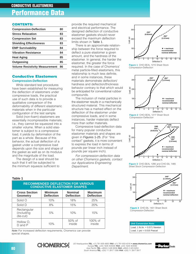
80US Headquarters TEL +(1) 781-935-4850 FAX +(1) 781-933-4318 • www.chomerics.com
Europe TEL +(44) 1628 404000 FAX +(44) 1628 404090Asia Pacific TEL +(852) 2 428 8008 FAX +(852) 2 423 8253
South America TEL +(55) 11 3917 1099 FAX +(55) 11 3917 0817
100
200
300
Deflection,%
Load
, psi
= maximumrecommendednominal deflection
1285.032"
(0.81mm)
1285.062" (1.57mm)
1485.062"
(1.57mm)
0 2 4 6 8 10 12 14 16 18 20
Figure 3 CHO-SEAL 1285 and CHO-SIL 1485Sheet Stock Compression-Deflection
100
200
300
Deflection,%
Load
, psi
= maximumrecommendednominal deflection
.045"(1.14mm)
.062"(1.57mm)
0 5 10 15 20 25 30
Figure 4 CHO-SIL 1401 Sheet StockCompression-Deflection
Unit Conversion Note:
Load, 1 lb./in. = 0.571 NewtonLoad, 1 psi = 0.015 Pascal
Cross Section Minimum Nominal MaximumGeometry Deflection Deflection Deflection
Solid O 10% 18% 25%
Solid D 8% 15% 20%
Rectangular(including 5% 10% 15%die-cut)
Hollow O, 50% of 100% ofD and P 10% inside inside
Note: For increased deflection requirements, Chomerics can providespecial shapes.
RECOMMENDED DEFLECTION FOR VARIOUSCONDUCTIVE ELASTOMER SHAPES
Table 1
Conductive ElastomersCompression-Deflection
While standard test procedureshave been established for measuringthe deflection of elastomers undercompressive loads, the practicaluse of such data is to provide aqualitative comparison of thedeformability of different elastomericmaterials when in the particularconfiguration of the test sample.
Solid (non-foam) elastomers areessentially incompressible materials;i.e., they cannot be squeezed into asmaller volume. When a solid elas-tomer is subject to a compressiveload, it yields by deformation of thepart as a whole. Because of thisbehavior, the actual deflection of agasket under a compressive loaddepends upon the size and shape ofthe gasket as well as on its modulusand the magnitude of the load.
The design of a seal should besuch that it will be subjected tothe minimum squeeze sufficient to
provide the required mechanicaland electrical performance. Thedesigned deflection of conductiveelastomer gaskets should neverexceed the maximum deflectionlimits shown in Table 1.
There is an approximate relation-ship between the force required todeflect a pure elastomer a givenamount, and the hardness of theelastomer. In general, the harder theelastomer, the greater the forcerequired. In the case of Chomerics’metal particle-filled elastomers, thisrelationship is much less definite,and in some instances, thesematerials demonstrate deflection/hardness and deflection/thicknessbehavior contrary to that which wouldbe anticipated for conventional rubbercompounds.
The inclusion of metal particles inthe elastomer results in a mechanicallystructured material. This mechanicalstructure has a marked effect on thedeflection of the elastomer undercompressive loads, and in someinstances, harder materials deflectmore than softer materials.
Compressive load-deflection datafor many popular conductiveelastomer materials and shapes aregiven in Figures 1-25. (For “linecontact” gaskets, it is more convenientto express the load in terms ofpounds per linear inch instead ofpounds per square inch).
For compression-deflection dataon other Chomerics gaskets, contactour Applications EngineeringDepartment.
100
200
300
Deflection,%
Load
, psi
= maximumrecommendednominal deflection
.032"(0.81mm)
.062"(1.57mm)
0 2 4 6 8 10 12 14 16 18 20
Figure 1 CHO-SEAL 1215 Sheet StockCompression-Deflection
100
200
300
Deflection,%
Load
, psi
= maximumrecommendednominal deflection
.032"(0.81mm)
.062"(1.57mm)
0 2 4 6 8 10 12 14 16 18 20
Figure 2 CHO-SEAL 1217 Sheet StockCompression-Deflection
CONTENTS:Compression-Deflection 80
Stress Relaxation 83
Compression Set 83
Shielding Effectiveness 83
EMP Survivability 84
Vibration Resistance 84
Heat Aging 85
Outgassing 85
Volume Resistivity Measurement 86
CONDUCTIVE ELASTOMERS
Performance Data
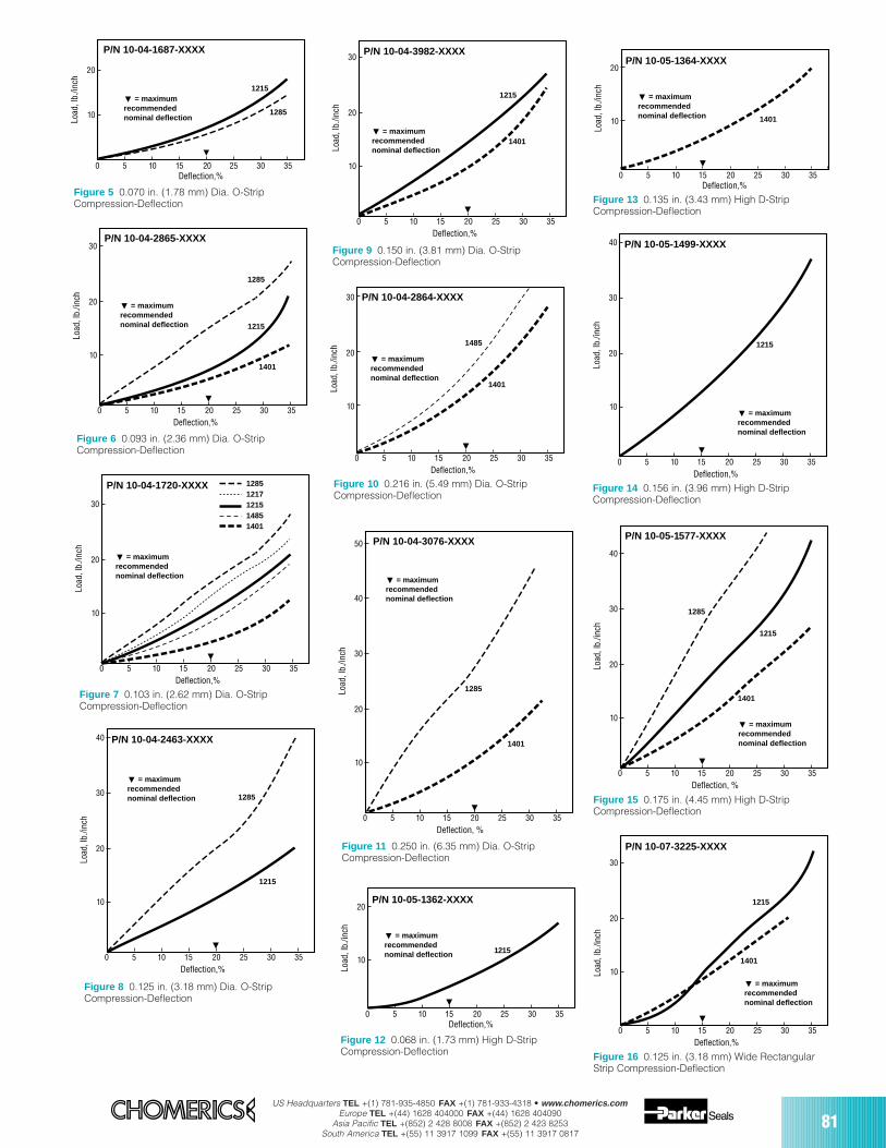
US Headquarters TEL +(1) 781-935-4850 FAX +(1) 781-933-4318 • www.chomerics.comEurope TEL +(44) 1628 404000 FAX +(44) 1628 404090
Asia Pacific TEL +(852) 2 428 8008 FAX +(852) 2 423 8253South America TEL +(55) 11 3917 1099 FAX +(55) 11 3917 0817
81
10
20
30
Load
, lb.
/inch
= maximumrecommendednominal deflection
0 5 10 15 20 25 30 35
12851217121514851401
P/N 10-04-1720-XXXX
Deflection,%
Figure 8 0.125 in. (3.18 mm) Dia. O-StripCompression-Deflection
10
20
30
Load
, lb.
/inch
= maximumrecommendednominal deflection
0 5 10 15 20 25 30 35
1485
1401
P/N 10-04-2864-XXXX
Deflection,%
Figure 11 0.250 in. (6.35 mm) Dia. O-StripCompression-Deflection
10
20
30
40
50
Load
, lb.
/inch
= maximumrecommendednominal deflection
0 5 10 15 20 25 30 35
1401
1285
P/N 10-04-3076-XXXX
Deflection, %
10
20
30
40
Load
, lb.
/inch
= maximumrecommendednominal deflection
0 5 10 15 20 25 30 35
1215
1285
P/N 10-04-2463-XXXX
Deflection,%
Figure 9 0.150 in. (3.81 mm) Dia. O-StripCompression-Deflection
10
20
30
Load
, lb.
/inch
= maximumrecommendednominal deflection
0 5 10 15 20 25 30 35
1215
1401
P/N 10-04-3982-XXXX
Deflection,%
Figure 10 0.216 in. (5.49 mm) Dia. O-StripCompression-Deflection
10
20
Deflection,%
Load
, lb.
/inch
= maximumrecommendednominal deflection
1215
1285
0 5 10 15 20 25 30 35
P/N 10-04-1687-XXXX
Figure 6 0.093 in. (2.36 mm) Dia. O-StripCompression-Deflection
Figure 5 0.070 in. (1.78 mm) Dia. O-StripCompression-Deflection
10
20
30
Load
, lb.
/inch
= maximumrecommendednominal deflection
0 5 10 15 20 25 30 35
1215
1285
1401
P/N 10-04-2865-XXXX
Deflection,%
Figure 7 0.103 in. (2.62 mm) Dia. O-StripCompression-Deflection
Figure 12 0.068 in. (1.73 mm) High D-StripCompression-Deflection
10
20
Deflection,%
Load
, lb.
/inch
= maximumrecommendednominal deflection
0 5 10 15 20 25 30 35
P/N 10-05-1362-XXXX
1215
Figure 13 0.135 in. (3.43 mm) High D-StripCompression-Deflection
10
20
Deflection,%
Load
, lb.
/inch
= maximumrecommendednominal deflection
0 5 10 15 20 25 30 35
P/N 10-05-1364-XXXX
1401
Figure 14 0.156 in. (3.96 mm) High D-StripCompression-Deflection
10
20
30
40
Load
, lb.
/inch
= maximumrecommendednominal deflection
0 5 10 15 20 25 30 35
1215
P/N 10-05-1499-XXXX
Deflection,%
10
20
30
40
Load
, lb.
/inch
= maximumrecommendednominal deflection
0 5 10 15 20 25 30 35
1215
1285
1401
P/N 10-05-1577-XXXX
Deflection, %
Figure 15 0.175 in. (4.45 mm) High D-StripCompression-Deflection
Figure 16 0.125 in. (3.18 mm) Wide RectangularStrip Compression-Deflection
10
20
30
Load
, lb.
/inch
= maximumrecommendednominal deflection
0 5 10 15 20 25 30 35
1215
1401
P/N 10-07-3225-XXXX
Deflection,%
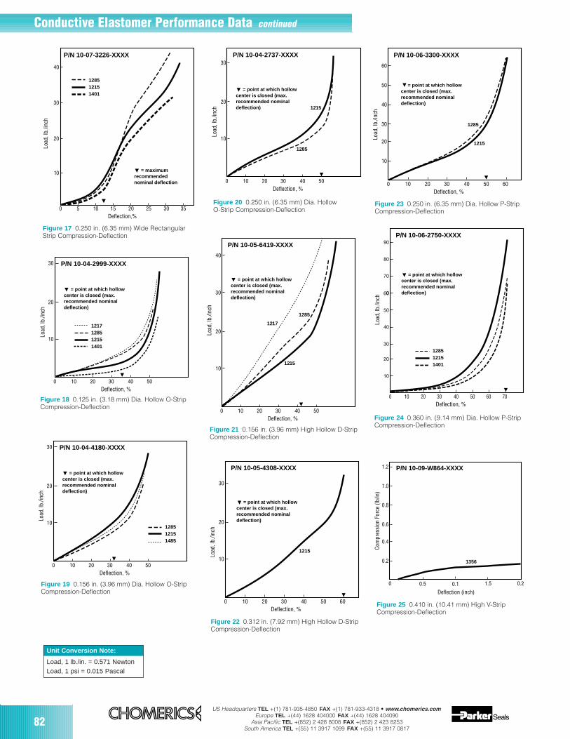
82US Headquarters TEL +(1) 781-935-4850 FAX +(1) 781-933-4318 • www.chomerics.com
Europe TEL +(44) 1628 404000 FAX +(44) 1628 404090Asia Pacific TEL +(852) 2 428 8008 FAX +(852) 2 423 8253
South America TEL +(55) 11 3917 1099 FAX +(55) 11 3917 0817
Conductive Elastomer Performance Data continued
10
20
30
Load
, lb.
/inch
0 10 20 30 40 50
P/N 10-04-2737-XXXX
Deflection, %
1215
1285
= point at which hollowcenter is closed (max.recommended nominaldeflection)
Figure 21 0.156 in. (3.96 mm) High Hollow D-StripCompression-Deflection
10
40
20
30
Load
, lb.
/inch
= point at which hollowcenter is closed (max.recommended nominaldeflection)
0 10 20 30 40 50
P/N 10-05-6419-XXXX
Deflection, %
1215
1217
1285
Figure 22 0.312 in. (7.92 mm) High Hollow D-StripCompression-Deflection
Figure 20 0.250 in. (6.35 mm) Dia. HollowO-Strip Compression-Deflection
10
20
30
Load
, lb.
/inch
0 10 20 30 40 50 60
P/N 10-05-4308-XXXX
Deflection, %
= point at which hollowcenter is closed (max.recommended nominaldeflection)
1215
20
40
60
10
30
50
Load
, lb.
/inch
0 10 20 30 40 50 60
P/N 10-06-3300-XXXX
Deflection, %
= point at which hollowcenter is closed (max.recommended nominaldeflection)
1215
1285
Figure 23 0.250 in. (6.35 mm) Dia. Hollow P-StripCompression-Deflection
Figure 24 0.360 in. (9.14 mm) Dia. Hollow P-StripCompression-Deflection
20
40
60
10
30
50
70
90
0
80
Load
, lb.
/inch
0 10 20 30 40 50 60 70
P/N 10-06-2750-XXXX
Deflection, %
= point at which hollowcenter is closed (max.recommended nominaldeflection)
128512151401
Unit Conversion Note:
Load, 1 lb./in. = 0.571 NewtonLoad, 1 psi = 0.015 Pascal
128512151401
10
20
30
40
Load
, lb.
/inch
= maximumrecommendednominal deflection
0 5 10 15 20 25 30 35
P/N 10-07-3226-XXXX
Deflection,%
Figure 18 0.125 in. (3.18 mm) Dia. Hollow O-StripCompression-Deflection
1217128512151401
10
20
30
Load
, lb.
/inch
0 10 20 30 40 50
P/N 10-04-2999-XXXX
Deflection, %
= point at which hollowcenter is closed (max.recommended nominaldeflection)
Figure 19 0.156 in. (3.96 mm) Dia. Hollow O-StripCompression-Deflection
128512151485
10
20
30
Load
, lb.
/inch
0 10 20 30 40 50
P/N 10-04-4180-XXXX
Deflection, %
= point at which hollowcenter is closed (max.recommended nominaldeflection)
Figure 17 0.250 in. (6.35 mm) Wide RectangularStrip Compression-Deflection
0.4
0.8
1.2
0.2
0.6
1.0
Com
pres
sion
For
ce (l
b/in
)
0 0.5 1.50.1 0.2
Deflection (inch)
1356
P/N 10-09-W864-XXXX
Figure 25 0.410 in. (10.41 mm) High V-StripCompression-Deflection
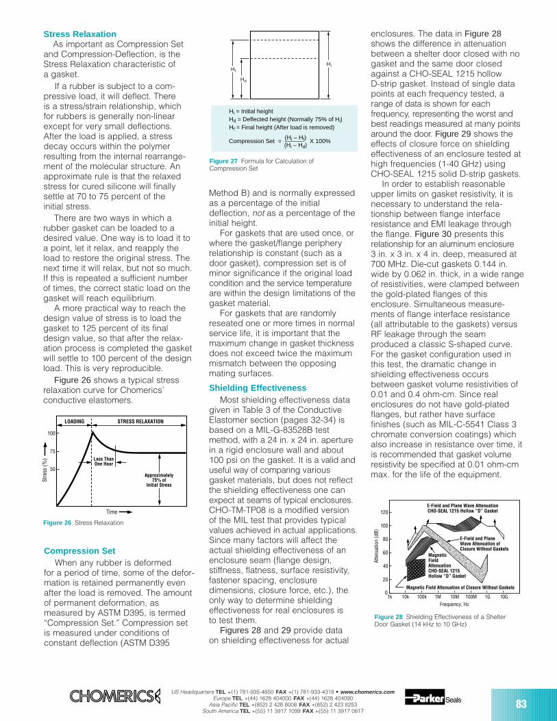
US Headquarters TEL +(1) 781-935-4850 FAX +(1) 781-933-4318 • www.chomerics.comEurope TEL +(44) 1628 404000 FAX +(44) 1628 404090
Asia Pacific TEL +(852) 2 428 8008 FAX +(852) 2 423 8253South America TEL +(55) 11 3917 1099 FAX +(55) 11 3917 0817
83
Stress RelaxationAs important as Compression Set
and Compression-Deflection, is theStress Relaxation characteristic ofa gasket.
If a rubber is subject to a com-pressive load, it will deflect. Thereis a stress/strain relationship, whichfor rubbers is generally non-linearexcept for very small deflections.After the load is applied, a stressdecay occurs within the polymerresulting from the internal rearrange-ment of the molecular structure. Anapproximate rule is that the relaxedstress for cured silicone will finallysettle at 70 to 75 percent of theinitial stress.
LOADING STRESS RELAXATION
Less ThanOne Hour
Approximately75% of
Initial Stress
Time
Stre
ss (%
)
100
75
50
Figure 26 Stress Relaxation
There are two ways in which arubber gasket can be loaded to adesired value. One way is to load it toa point, let it relax, and reapply theload to restore the original stress. Thenext time it will relax, but not so much.If this is repeated a sufficient numberof times, the correct static load on thegasket will reach equilibrium.
A more practical way to reach thedesign value of stress is to load thegasket to 125 percent of its finaldesign value, so that after the relax-ation process is completed the gasketwill settle to 100 percent of the designload. This is very reproducible.
Figure 26 shows a typical stressrelaxation curve for Chomerics’conductive elastomers.
Compression SetWhen any rubber is deformed
for a period of time, some of the defor-mation is retained permanently evenafter the load is removed. The amountof permanent deformation, asmeasured by ASTM D395, is termed“Compression Set.” Compression setis measured under conditions ofconstant deflection (ASTM D395
Method B) and is normally expressedas a percentage of the initialdeflection, not as a percentage of theinitial height.
For gaskets that are used once, orwhere the gasket/flange peripheryrelationship is constant (such as adoor gasket), compression set is ofminor significance if the original loadcondition and the service temperatureare within the design limitations of thegasket material.
For gaskets that are randomlyreseated one or more times in normalservice life, it is important that themaximum change in gasket thicknessdoes not exceed twice the maximummismatch between the opposingmating surfaces.
Shielding EffectivenessMost shielding effectiveness data
given in Table 3 of the ConductiveElastomer section (pages 32-34) isbased on a MIL-G-83528B testmethod, with a 24 in. x 24 in. aperturein a rigid enclosure wall and about100 psi on the gasket. It is a valid anduseful way of comparing variousgasket materials, but does not reflectthe shielding effectiveness one canexpect at seams of typical enclosures.CHO-TM-TP08 is a modified versionof the MIL test that provides typicalvalues achieved in actual applications.Since many factors will affect theactual shielding effectiveness of anenclosure seam (flange design,stiffness, flatness, surface resistivity,fastener spacing, enclosuredimensions, closure force, etc.), theonly way to determine shieldingeffectiveness for real enclosures isto test them.
Figures 28 and 29 provide data on shielding effectiveness for actual
Hd
Hi
Hi = Initial heightHd = Deflected height (Normally 75% of Hi)Hf = Final height (After load is removed)
Hf
Compression Set = X 100%(Hi – Hf)(Hi – Hd)
Figure 27 Formula for Calculation ofCompression Set
enclosures. The data in Figure 28shows the difference in attenuationbetween a shelter door closed with nogasket and the same door closedagainst a CHO-SEAL 1215 hollowD-strip gasket. Instead of single datapoints at each frequency tested, arange of data is shown for eachfrequency, representing the worst andbest readings measured at many pointsaround the door. Figure 29 shows theeffects of closure force on shieldingeffectiveness of an enclosure tested athigh frequencies (1-40 GHz) usingCHO-SEAL 1215 solid D-strip gaskets.
In order to establish reasonableupper limits on gasket resistivity, it isnecessary to understand the rela-tionship between flange interfaceresistance and EMI leakage throughthe flange. Figure 30 presents thisrelationship for an aluminum enclosure3 in. x 3 in. x 4 in. deep, measured at700 MHz. Die-cut gaskets 0.144 in.wide by 0.062 in. thick, in a wide rangeof resistivities, were clamped betweenthe gold-plated flanges of thisenclosure. Simultaneous measure-ments of flange interface resistance(all attributable to the gaskets) versusRF leakage through the seamproduced a classic S-shaped curve.For the gasket configuration used inthis test, the dramatic change inshielding effectiveness occursbetween gasket volume resistivities of0.01 and 0.4 ohm-cm. Since realenclosures do not have gold-platedflanges, but rather have surfacefinishes (such as MIL-C-5541 Class 3chromate conversion coatings) whichalso increase in resistance over time, itis recommended that gasket volumeresistivity be specified at 0.01 ohm-cmmax. for the life of the equipment.
0
20
40
60
80
100
120
1k 10k 100k 1M 10M 100M 1G 10GFrequency, Hz
Atte
nuat
ion
(dB)
E-Field and PlaneWave Attenuation ofClosure Without Gaskets
MagneticFieldAttenuationCHO-SEAL 1215Hollow “D” Gasket
E-Field and Plane Wave AttenuationCHO-SEAL 1215 Hollow “D” Gasket
Magnetic Field Attenuation of Closure Without Gaskets
Figure 28 Shielding Effectiveness of a ShelterDoor Gasket (14 kHz to 10 GHz)

84US Headquarters TEL +(1) 781-935-4850 FAX +(1) 781-933-4318 • www.chomerics.com
Europe TEL +(44) 1628 404000 FAX +(44) 1628 404090Asia Pacific TEL +(852) 2 428 8008 FAX +(852) 2 423 8253
South America TEL +(55) 11 3917 1099 FAX +(55) 11 3917 0817
kA/inch of gasket (peak-to-peak).Pure silver (1224) and silver-plated-aluminum filled (1285) gaskets haveless current carrying capability thansilver-plated-copper materials, butare generally acceptable for EMPhardened systems (depending onspecific EMP threat levels, gasketcross section dimensions, etc.).
Vibration ResistanceCertain conductive elastomers are
electrically stable during aircraft-levelvibration environments, while othersare not. The key factor which deter-mines vibration resistance is theshape and surface texture of the fillerparticles. Smooth, spherical fillers(such as those used in silver-plated-
Figure 31 EMP Current Response of ConductiveElastomer Gaskets
Figure 32 Scanning Electron Microscopy Illustrates EMP DamageMechanism for Silver/Glass Elastomers
0.25
0 0.5 1.0 1.5 2.0 2.5
0.50
0.75
1.00
1.25
1.50
1.75
Gas
ket R
esis
ance
(mΩ
/in.)
Material #1(1350)
Material #2(1224)
Material #4(1215)
Material #3(1285)
Peak Pulse Current (kA/in.)
10
00 1 2 3 4 5 6
20
30
40
50
60
Leak
age
(dB)
Ag/Glass Filler
Spherical Ag/Cu Filler
Chomerics Ag/Cu Filler
Vibration (g)
Figure 33 Effects of Vibration on ShieldingEffectiveness of Conductive Elastomer Gaskets
EMP SurvivabilityIn order for an enclosure to
continue providing EMI isolationduring and after an EMP environment,the conductive gaskets at joints andseams must be capable of carryingEMP-induced current pulses withoutlosing their conductivity. Figure 31shows the EMP current response ofvarious types of conductive elastomergaskets. Note that gaskets based onsilver-plated-glass fillers (1350)become nonconductive at low levelsof EMP current, and should thereforenot be used when EMP is a designconsideration. Figure 32 is anelectron microscope photo whichclearly shows the damage mechanism.Silver-plated-copper filled (1215)gaskets have the highest resistanceto EMP type currents, showing noloss of conductivity even at 2.5
0.1
0.01
1.0
10.0
100.0
0 10 20 30 40 50 60Shielding Degradation, dB
Inte
rfac
e R
esis
tanc
e, m
illio
hms
Tested at 700 MHzEnclosure: 3" X 3" X 4" Deepwith Gold-Plated FlangesEnclosure Material: .500" Aluminum
Figure 30 Interface Resistance vs. ShieldingDegradation at a Flange Joint
Unit Conversion Note:
Gasket Resistance, 1 mΩ/in.= 25.4 Ω/mmPeak Pulse Current, 1 kA/in.= 25.4 kA/mm
Conductive Elastomer Performance Data continued
glass materials) tend to move apartduring vibration, leading to dramaticincreases in resistance and loss ofshielding effectiveness (althoughthey normally recover their initialproperties after the vibration hasended). Rough, less sphericalparticles resist vibration with verylittle electrical degradation. Figure 33shows the effects of vibration onthree types of conductive gaskets.Although Chomerics’ silver-plated-copper filled 1215 gasket, with rough,irregular particle agglomerations,exhibits excellent stability duringvibration, users of conductiveelastomers should be aware thatsmooth, spherical silver-plated-copper fillers can be almost asunstable as silver-plated-glass fillers.
2010
30405060708090
100110120130
0.1 1 10 40 100Frequency, GHz
CHO-SEAL 1215 Solid “D”Gasket
2 lbs/in.
30 lbs/in.
45 lbs/in.
12 lbs/in.
MeasurementLimit of
Instrumentation
Atte
nuat
ion
(dB)
Figure 29 Effect of Closure Force on ShieldingEffectiveness (1 GHz to 40 GHz)
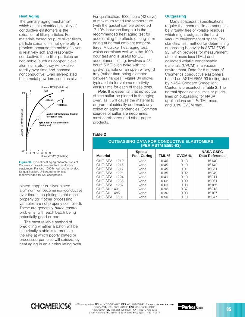
Special NASA GSFCMaterial Post Curing TML % CVCM % Data ReferenceCHO-SEAL 1212 None 0.40 0.13 15140CHO-SEAL 1215 None 0.45 0.10 15142CHO-SEAL 1217 None 0.45 0.01 15231CHO-SEAL 1221 None 0.35 0.02 15249CHO-SEAL 1224 None 0.41 0.10 15211CHO-SEAL 1285 None 0.62 0.09 15251CHO-SEAL 1287 None 0.63 0.03 15165CHO-SIL 1401 None 0.92 0.37 15213CHO-SIL 1485 None 0.36 0.08 15167CHO-SEAL 1501 None 0.50 0.10 15247
OUTGASSING DATA FOR CONDUCTIVE ELASTOMERS(PER ASTM E595-93)
US Headquarters TEL +(1) 781-935-4850 FAX +(1) 781-933-4318 • www.chomerics.comEurope TEL +(44) 1628 404000 FAX +(44) 1628 404090
Asia Pacific TEL +(852) 2 428 8008 FAX +(852) 2 423 8253South America TEL +(55) 11 3917 1099 FAX +(55) 11 3917 0817
85
Heat AgingThe primary aging mechanism which affects electrical stability ofconductive elastomers is theoxidation of filler particles. Formaterials based on pure silver fillers,particle oxidation is not generally aproblem because the oxide of silveris relatively soft and reasonablyconductive. If the filler particles arenon-noble (such as copper, nickel,aluminum, etc.) they will oxidizereadily over time and becomenonconductive. Even silver-platedbase metal powders, such as silver-
.001
.0100 500 1000
Volu
me
Res
istiv
ity (o
hm-c
m)
0 8 16 24 32 40 48Hours at 150°C (Solid Line)
48 Hours
1000 Hours
Aged at 150° in Unflanged Condition(See bottom axis)
Aged at 125° in Flanged Condition(See top axis)
Hours at 125°C (Dotted Line)
Figure 34 Typical heat aging characteristics ofChomerics’ plated-powder-filled conductiveelastomers. Flanged 1000-hr test recommendedfor qualification. Unflanged 48-hr. testrecommended for QC acceptance.
Table 2
plated-copper or silver-plated-aluminum will become non-conductiveover time if the plating is not doneproperly (or if other processingvariables are not properly controlled).These are generally batch controlproblems, with each batch beingpotentially good or bad.
The most reliable method ofpredicting whether a batch will beelectrically stable is to promotethe rate at which poorly plated orprocessed particles will oxidize, byheat aging in an air circulating oven.
For qualification, 1000 hours (42 days)at maximum rated use temperature(with the gasket sample deflected7-10% between flanges) is the
recommended heat aging test foraccelerating the effects of long-termaging at normal ambient tempera-tures. A quicker heat aging test,which correlates well with the 1000hour test and is useful for QCacceptance testing, involves a 48hour/150°C oven bake with thegasket sample on an open wire-gridtray (rather than being clampedbetween flanges). Figure 34 showstypical data for volume resistivityversus time for each of these tests.
Note: It is essential that no sourceof free sulfur be placed in the agingoven, as it will cause the material todegrade electrically and mask anyoxidation aging tendencies. Commonsources of sulfur are neoprenes,most cardboards and other paperproducts.
OutgassingMany spacecraft specifications
require that nonmetallic componentsbe virtually free of volatile residueswhich might outgas in the hardvacuum environment of space. Thestandard test method for determiningoutgassing behavior is ASTM E595-93, which provides for measurementof total mass loss (TML) andcollected volatile condensablematerials (CVCM) in a vacuumenvironment. Data for a number ofChomerics conductive elastomers,based on ASTM E595-93 testing doneby NASA Goddard SpaceflightCenter, is presented in Table 2. Thenormal specification limits or guide-lines on outgassing for NASAapplications are 1% TML max.,and 0.1% CVCM max.
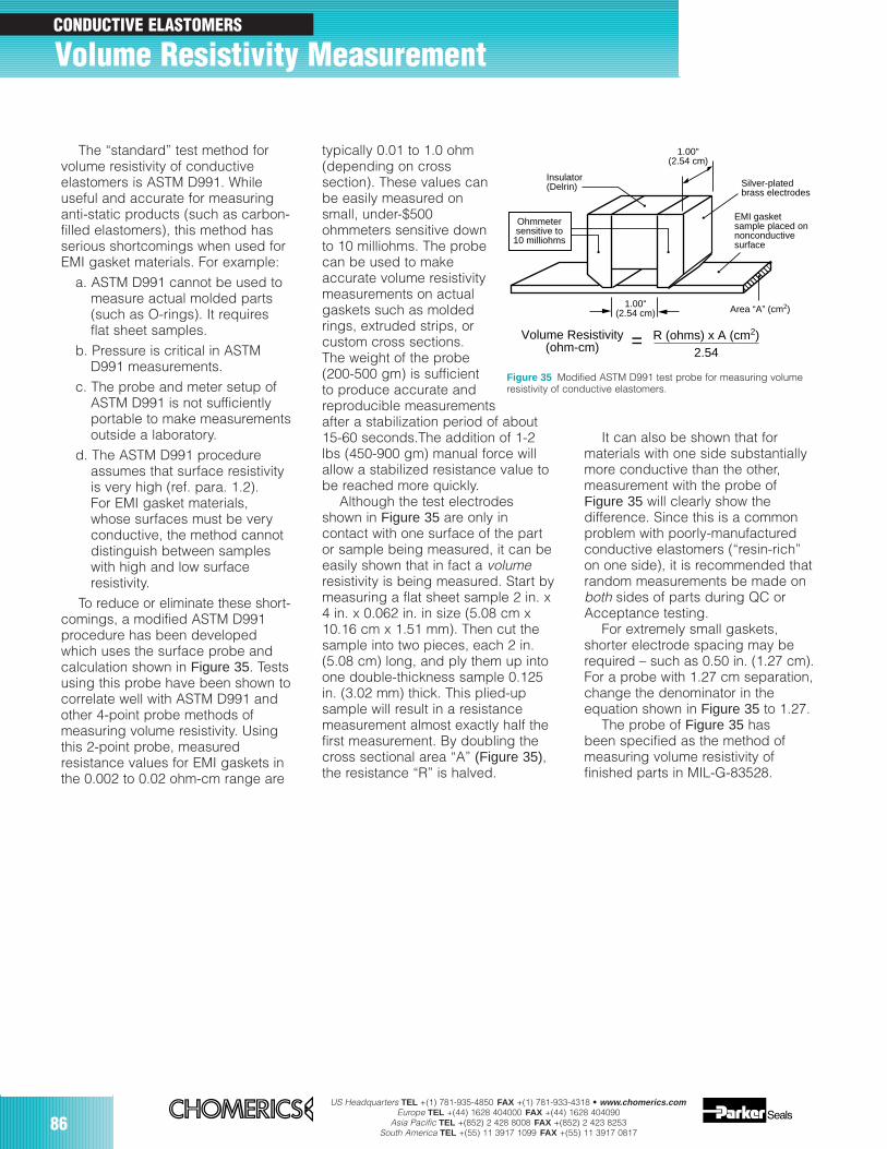
86US Headquarters TEL +(1) 781-935-4850 FAX +(1) 781-933-4318 • www.chomerics.com
Europe TEL +(44) 1628 404000 FAX +(44) 1628 404090Asia Pacific TEL +(852) 2 428 8008 FAX +(852) 2 423 8253
South America TEL +(55) 11 3917 1099 FAX +(55) 11 3917 0817
It can also be shown that formaterials with one side substantiallymore conductive than the other,measurement with the probe ofFigure 35 will clearly show thedifference. Since this is a commonproblem with poorly-manufacturedconductive elastomers (“resin-rich”on one side), it is recommended thatrandom measurements be made onboth sides of parts during QC orAcceptance testing.
For extremely small gaskets,shorter electrode spacing may berequired – such as 0.50 in. (1.27 cm).For a probe with 1.27 cm separation,change the denominator in theequation shown in Figure 35 to 1.27.
The probe of Figure 35 hasbeen specified as the method ofmeasuring volume resistivity offinished parts in MIL-G-83528.
The “standard” test method forvolume resistivity of conductiveelastomers is ASTM D991. Whileuseful and accurate for measuringanti-static products (such as carbon-filled elastomers), this method hasserious shortcomings when used forEMI gasket materials. For example:
a. ASTM D991 cannot be used tomeasure actual molded parts(such as O-rings). It requiresflat sheet samples.
b. Pressure is critical in ASTMD991 measurements.
c. The probe and meter setup ofASTM D991 is not sufficientlyportable to make measurementsoutside a laboratory.
d. The ASTM D991 procedureassumes that surface resistivityis very high (ref. para. 1.2).For EMI gasket materials,whose surfaces must be veryconductive, the method cannotdistinguish between sampleswith high and low surfaceresistivity.
To reduce or eliminate these short-comings, a modified ASTM D991procedure has been developedwhich uses the surface probe andcalculation shown in Figure 35. Testsusing this probe have been shown tocorrelate well with ASTM D991 andother 4-point probe methods ofmeasuring volume resistivity. Usingthis 2-point probe, measuredresistance values for EMI gaskets inthe 0.002 to 0.02 ohm-cm range are
typically 0.01 to 1.0 ohm(depending on crosssection). These values canbe easily measured onsmall, under-$500ohmmeters sensitive downto 10 milliohms. The probecan be used to makeaccurate volume resistivitymeasurements on actualgaskets such as moldedrings, extruded strips, orcustom cross sections.The weight of the probe(200-500 gm) is sufficientto produce accurate andreproducible measurementsafter a stabilization period of about15-60 seconds.The addition of 1-2lbs (450-900 gm) manual force willallow a stabilized resistance value tobe reached more quickly.
Although the test electrodesshown in Figure 35 are only incontact with one surface of the partor sample being measured, it can beeasily shown that in fact a volumeresistivity is being measured. Start bymeasuring a flat sheet sample 2 in. x4 in. x 0.062 in. in size (5.08 cm x10.16 cm x 1.51 mm). Then cut thesample into two pieces, each 2 in.(5.08 cm) long, and ply them up intoone double-thickness sample 0.125in. (3.02 mm) thick. This plied-upsample will result in a resistancemeasurement almost exactly half thefirst measurement. By doubling thecross sectional area “A” (Figure 35),the resistance “R” is halved.
Insulator(Delrin)
Ohmmetersensitive to10 milliohms
EMI gasketsample placed onnonconductivesurface
Silver-platedbrass electrodes
1.00"(2.54 cm)
1.00"(2.54 cm)
Area “A” (cm2)
Volume Resistivity(ohm-cm)
R (ohms) x A (cm2)2.54
=
Figure 35 Modified ASTM D991 test probe for measuring volumeresistivity of conductive elastomers.
CONDUCTIVE ELASTOMERS
Volume Resistivity Measurement

US Headquarters TEL +(1) 781-935-4850 FAX +(1) 781-933-4318 • www.chomerics.comEurope TEL +(44) 1628 404000 FAX +(44) 1628 404090
Asia Pacific TEL +(852) 2 428 8008 FAX +(852) 2 423 8253South America TEL +(55) 11 3917 1099 FAX +(55) 11 3917 0817
87
CONDUCTIVE ELASTOMERS
Part Number Index
10-00-0008-XXXX . . . . . . . . . .O-Ring . . . . . . . . .6410-00-0010-XXXX . . . . . . . . . .O-Ring . . . . . . . . .6410-00-0012-XXXX . . . . . . . . . .O-Ring . . . . . . . . .6410-00-0014-XXXX . . . . . . . . . .O-Ring . . . . . . . . .6410-00-0020-XXXX . . . . . . . . . .O-Ring . . . . . . . . .6510-00-0024-XXXX . . . . . . . . . .O-Ring . . . . . . . . .6510-00-0028-XXXX . . . . . . . . . .O-Ring . . . . . . . . .6510-00-0032-XXXX . . . . . . . . . .O-Ring . . . . . . . . .6510-00-0038-XXXX . . . . . . . . . .O-Ring . . . . . . . . .6510-00-0044-XXXX . . . . . . . . . .O-Ring . . . . . . . . .6510-00-0052-XXXX . . . . . . . . . .O-Ring . . . . . . . . .6510-00-1342-XXXX . . . . . . . . . .O-Ring . . . . . . . . .6410-00-1354-XXXX . . . . . . . . . .O-Ring . . . . . . . . .6510-00-1359-XXXX . . . . . . . . . .O-Ring . . . . . . . . .6510-00-1360-XXXX . . . . . . . . . .O-Ring . . . . . . . . .6510-00-1376-XXXX . . . . . . . . . .O-Ring . . . . . . . . .6410-00-1378-XXXX . . . . . . . . . .O-Ring . . . . . . . . .6510-00-1405-XXXX . . . . . . . . . .O-Ring . . . . . . . . .6410-00-1406-XXXX . . . . . . . . . .O-Ring . . . . . . . . .6410-00-1407-XXXX . . . . . . . . . .O-Ring . . . . . . . . .6410-00-1413-XXXX . . . . . . . . . .O-Ring . . . . . . . . .6410-00-1459-XXXX . . . . . . . . . .O-Ring . . . . . . . . .6510-00-1478-XXXX . . . . . . . . . .O-Ring . . . . . . . . .6410-00-1573-XXXX . . . . . . . . . .O-Ring . . . . . . . . .6510-00-1607-XXXX . . . . . . . . . .O-Ring . . . . . . . . .6510-00-1608-XXXX . . . . . . . . . .O-Ring . . . . . . . . .6510-00-1631-XXXX . . . . . . . . . .O-Ring . . . . . . . . .6410-00-1689-XXXX . . . . . . . . . .O-Ring . . . . . . . . .6410-00-1690-XXXX . . . . . . . . . .O-Ring . . . . . . . . .6410-00-1691-XXXX . . . . . . . . . .O-Ring . . . . . . . . .6510-00-1746-XXXX . . . . . . . . . .O-Ring . . . . . . . . .6510-00-1747-XXXX . . . . . . . . . .O-Ring . . . . . . . . .6510-00-1754-XXXX . . . . . . . . . .O-Ring . . . . . . . . .6510-00-1770-XXXX . . . . . . . . . .O-Ring . . . . . . . . .6410-00-1782-XXXX . . . . . . . . . .O-Ring . . . . . . . . .6510-00-1827-XXXX . . . . . . . . . .O-Ring . . . . . . . . .6510-00-1843-XXXX . . . . . . . . . .O-Ring . . . . . . . . .6410-00-1844-XXXX . . . . . . . . . .O-Ring . . . . . . . . .6410-00-1845-XXXX . . . . . . . . . .O-Ring . . . . . . . . .6510-00-1846-XXXX . . . . . . . . . .O-Ring . . . . . . . . .6510-00-1847-XXXX . . . . . . . . . .O-Ring . . . . . . . . .6510-00-1921-XXXX . . . . . . . . . .O-Ring . . . . . . . . .6510-00-1980-XXXX . . . . . . . . . .O-Ring . . . . . . . . .6410-00-1981-XXXX . . . . . . . . . .O-Ring . . . . . . . . .6410-00-2029-XXXX . . . . . . . . . .O-Ring . . . . . . . . .6410-00-2030-XXXX . . . . . . . . . .O-Ring . . . . . . . . .6510-00-2031-XXXX . . . . . . . . . .O-Ring . . . . . . . . .6510-00-2040-XXXX . . . . . . . . . .O-Ring . . . . . . . . .6510-00-2065-XXXX . . . . . . . . . .O-Ring . . . . . . . . .6410-00-2066-XXXX . . . . . . . . . .O-Ring . . . . . . . . .6410-00-2068-XXXX . . . . . . . . . .O-Ring . . . . . . . . .6410-00-2069-XXXX . . . . . . . . . .O-Ring . . . . . . . . .6410-00-2070-XXXX . . . . . . . . . .O-Ring . . . . . . . . .6410-00-2071-XXXX . . . . . . . . . .O-Ring . . . . . . . . .6410-00-2072-XXXX . . . . . . . . . .O-Ring . . . . . . . . .6510-00-2075-XXXX . . . . . . . . . .O-Ring . . . . . . . . .6410-00-2076-XXXX . . . . . . . . . .O-Ring . . . . . . . . .6410-00-2084-XXXX . . . . . . . . . .O-Ring . . . . . . . . .6410-00-2085-XXXX . . . . . . . . . .O-Ring . . . . . . . . .6410-00-2086-XXXX . . . . . . . . . .O-Ring . . . . . . . . .6510-00-2087-XXXX . . . . . . . . . .O-Ring . . . . . . . . .6510-00-2226-XXXX . . . . . . . . . .O-Ring . . . . . . . . .6410-00-2227-XXXX . . . . . . . . . .O-Ring . . . . . . . . .6410-00-2228-XXXX . . . . . . . . . .O-Ring . . . . . . . . .6410-00-2229-XXXX . . . . . . . . . .O-Ring . . . . . . . . .6510-00-2230-XXXX . . . . . . . . . .O-Ring . . . . . . . . .6510-00-2231-XXXX . . . . . . . . . .O-Ring . . . . . . . . .6410-00-2232-XXXX . . . . . . . . . .O-Ring . . . . . . . . .6410-00-2233-XXXX . . . . . . . . . .O-Ring . . . . . . . . .6410-00-2259-XXXX . . . . . . . . . .O-Ring . . . . . . . . .64
The following table identifies the gasket type and page number within this Handbook for standardextruded and molded elastomer parts, custom extrusions and sheet stock.
Table 110-00-2320-XXXX . . . . . . . . . .O-Ring . . . . . . . . .6510-00-2321-XXXX . . . . . . . . . .O-Ring . . . . . . . . .6510-00-2535-XXXX . . . . . . . . . .O-Ring . . . . . . . . .6410-00-2536-XXXX . . . . . . . . . .O-Ring . . . . . . . . .6410-00-2677-XXXX . . . . . . . . . .O-Ring . . . . . . . . .6510-00-2777-XXXX . . . . . . . . . .O-Ring . . . . . . . . .6410-00-3550-XXXX . . . . . . . . . .O-Ring . . . . . . . . .6510-00-3811-XXXX . . . . . . . . . .O-Ring . . . . . . . . .6410-00-4123-XXXX . . . . . . . . . .O-Ring . . . . . . . . .6510-00-4124-XXXX . . . . . . . . . .O-Ring . . . . . . . . .6510-00-4452-XXXX . . . . . . . . . .O-Ring . . . . . . . . .6510-00-4685-XXXX . . . . . . . . . .O-Ring . . . . . . . . .6510-00-5983-XXXX . . . . . . . . . .O-Ring . . . . . . . . .64
10-01-1120-XXXX . . . . . . . . . .D-Ring . . . . . . . . .6310-01-1131-XXXX . . . . . . . . . .D-Ring . . . . . . . . .6310-01-1142-XXXX . . . . . . . . . .D-Ring . . . . . . . . .6310-01-1143-XXXX . . . . . . . . . .D-Ring . . . . . . . . .6310-01-1144-XXXX . . . . . . . . . .D-Ring . . . . . . . . .6310-01-1154-XXXX . . . . . . . . . .D-Ring . . . . . . . . .6310-01-1187-XXXX . . . . . . . . . .D-Ring . . . . . . . . .6310-01-1188-XXXX . . . . . . . . . .D-Ring . . . . . . . . .6310-01-1238-XXXX . . . . . . . . . .D-Ring . . . . . . . . .6310-01-1239-XXXX . . . . . . . . . .D-Ring . . . . . . . . .6310-01-1240-XXXX . . . . . . . . . .D-Ring . . . . . . . . .6310-01-1241-XXXX . . . . . . . . . .D-Ring . . . . . . . . .6310-01-1264-XXXX . . . . . . . . . .D-Ring . . . . . . . . .6310-01-1375-XXXX . . . . . . . . . .D-Ring . . . . . . . . .6310-01-1601-XXXX . . . . . . . . . .D-Ring . . . . . . . . .6310-01-1623-XXXX . . . . . . . . . .D-Ring . . . . . . . . .6310-01-1628-XXXX . . . . . . . . . .D-Ring . . . . . . . . .6310-01-1766-XXXX . . . . . . . . . .D-Ring . . . . . . . . .6310-01-2238-XXXX . . . . . . . . . .D-Ring . . . . . . . . .6310-01-6515-XXXX . . . . . . . . . .D-Ring . . . . . . . . .6310-01-6520-XXXX . . . . . . . . . .D-Ring . . . . . . . . .6310-01-6525-XXXX . . . . . . . . . .D-Ring . . . . . . . . .6310-01-6535-XXXX . . . . . . . . . .D-Ring . . . . . . . . .6310-01-6540-XXXX . . . . . . . . . .D-Ring . . . . . . . . .6310-01-6565-XXXX . . . . . . . . . .D-Ring . . . . . . . . .63
10-02-1388-XXXX . . . . . . . .Flat Washer . . . . . . .6610-02-1492-XXXX . . . . . . . .Flat Washer . . . . . . .6610-02-1493-XXXX . . . . . . . .Flat Washer . . . . . . .6610-02-1494-XXXX . . . . . . . .Flat Washer . . . . . . .6610-02-1859-XXXX . . . . . . . .Flat Washer . . . . . . .6610-02-2736-XXXX . . . . . . . .Flat Washer . . . . . . .66
10-03-1388-XXXX . . . . . . . .Flat Washer . . . . . . .6610-03-1492-XXXX . . . . . . . .Flat Washer . . . . . . .6610-03-1493-XXXX . . . . . . . .Flat Washer . . . . . . .6610-03-1494-XXXX . . . . . . . .Flat Washer . . . . . . .6610-03-1859-XXXX . . . . . . . .Flat Washer . . . . . . .6610-03-2736-XXXX . . . . . . . .Flat Washer . . . . . . .66
10-04-1687-XXXX . . . . . . .Solid O-Strip . . . . . . .4110-04-1720-XXXX . . . . . . .Solid O-Strip . . . . . . .4110-04-1721-XXXX . . . . . . .Solid O-Strip . . . . . . .4110-04-2463-XXXX . . . . . . .Solid O-Strip . . . . . . .4110-04-2561-XXXX . . . . . . .Solid O-Strip . . . . . . .4110-04-2657-XXXX . . . . . . .Solid O-Strip . . . . . . .4110-04-2737-XXXX . . . . . . .Hollow O-Strip . . . . . .4310-04-2862-XXXX . . . . . . .Solid O-Strip . . . . . . .4110-04-2864-XXXX . . . . . . .Solid O-Strip . . . . . . .4110-04-2865-XXXX . . . . . . .Solid O-Strip . . . . . . .4110-04-2866-XXXX . . . . . . .Solid O-Strip . . . . . . .4110-04-2999-XXXX . . . . . . .Hollow O-Strip . . . . . .4210-04-3004-XXXX . . . . . . .Hollow O-Strip . . . . . .43
10-04-3076-XXXX . . . . . . .Solid O-Strip . . . . . .4110-04-3077-XXXX . . . . . . .Solid O-Strip . . . . . .4110-04-3122-XXXX . . . . . . .Hollow O-Strip . . . . . .4310-04-3221-XXXX . . . . . . .Hollow O-Strip . . . . . .4310-04-3231-XXXX . . . . . . .Solid O-Strip . . . . . .4110-04-3509-XXXX . . . . . . .Solid O-Strip . . . . . .4110-04-3560-XXXX . . . . . . .Solid O-Strip . . . . . .4110-04-3649-XXXX . . . . . . .Hollow O-Strip . . . . . .4310-04-3652-XXXX . . . . . . .Hollow O-Strip . . . . . .4310-04-3982-XXXX . . . . . . .Solid O-Strip . . . . . .4110-04-4034-XXXX . . . . . . .Hollow O-Strip . . . . . .4310-04-4155-XXXX . . . . . . .Hollow O-Strip . . . . . .4310-04-4180-XXXX . . . . . . .Hollow O-Strip . . . . . .4310-04-4254-XXXX . . . . . . .Hollow O-Strip . . . . . .4310-04-5514-XXXX . . . . . . .Hollow O-Strip . . . . . .4210-04-5515-XXXX . . . . . . .Hollow O-Strip . . . . . .4310-04-5516-XXXX . . . . . . .Hollow O-Strip . . . . . .4310-04-5572-XXXX . . . . . . .Hollow O-Strip . . . . . .4310-04-6386-XXXX . . . . . . .Solid O-Strip . . . . . .4110-04-8133-XXXX . . . . . . .Hollow O-Strip . . . . . .4310-04-8363-XXXX . . . . . . .Hollow O-Strip . . . . . .4210-04-8817-XXXX . . . . . . .Hollow O-Strip . . . . . .4210-04-9139-XXXX . . . . . . .Solid O-Strip . . . . . .4110-04-9732-XXXX . . . . . . .Hollow O-Strip . . . . . .4310-04-9769-XXXX . . . . . . .Solid O-Strip . . . . . .4210-04-C317-XXXX . . . . . . .Solid O-Strip . . . . . .4110-04-M211-XXXX . . . . . .Hollow O-Strip . . . . . .4210-04-W137-XXXX . . . . . .Hollow O-Strip . . . . . .4210-04-W163-XXXX . . . . . .Hollow O-Strip . . . . . .4210-04-W201-XXXX . . . . . .Hollow O-Strip . . . . . .4210-04-W202-XXXX . . . . . .Hollow O-Strip . . . . . .4210-04-W203-XXXX . . . . . .Hollow O-Strip . . . . . .4210-04-W204-XXXX . . . . . .Hollow O-Strip . . . . . .4210-04-W267-XXXX . . . . . .Hollow O-Strip . . . . . .4210-04-W293-XXXX . . . . . .Hollow O-Strip . . . . . .4210-04-W775-XXXX . . . . . .Hollow O-Strip . . . . . .42
10-05-1362-XXXX . . . . . . .Solid D-Strip . . . . . . .4410-05-1363-XXXX . . . . . . .Solid D-Strip . . . . . . .4410-05-1364-XXXX . . . . . . .Solid D-Strip . . . . . . .4410-05-1499-XXXX . . . . . . .Solid D-Strip . . . . . . .4410-05-1577-XXXX . . . . . . .Solid D-Strip . . . . . . .4410-05-2618-XXXX . . . . . . .Solid D-Strip . . . . . . .4410-05-3224-XXXX . . . . . . .Solid D-Strip . . . . . . .4410-05-3369-XXXX . . . . . . .Hollow D-Strip . . . . . .4510-05-4035-XXXX . . . . . .Custom Extrusion . . . . .5410-05-4202-XXXX . . . . . . .Hollow D-Strip . . . . . .4410-05-4282-XXXX . . . . . . .Hollow D-Strip . . . . . .4510-05-4308-XXXX . . . . . . .Hollow D-Strip . . . . . .4510-05-4318-XXXX . . . . . . .Hollow D-Strip . . . . . .4510-05-4542-XXXX . . . . . . .Hollow D-Strip . . . . . .4510-05-4699-XXX . . . . . . . .Solid D-Strip . . . . . . .4410-05-5589-XXXX . . . . . . .Solid D-Strip . . . . . . .4410-05-6221-XXXX . . . . . .Custom Extrusion . . . . .5410-05-6394-XXXX . . . . . . .Hollow D-Strip . . . . . .4510-05-6419-XXXX . . . . . . .Hollow D-Strip . . . . . .4410-05-6991-XXXX . . . . . . .Hollow D-Strip . . . . . .4510-05-8635-XXXX . . . . . .Custom Extrusion . . . . .5410-05-10648-XXXX . . . . .Custom Extrusion . . . . .5410-05-A283-XXXX . . . . . . .Solid D-Strip . . . . . . .4410-05-A967-XXXX . . . . .Custom Extrusion . . . . .5410-05-C038-XXXX . . . . . .Hollow D-Strip . . . . . .4510-05-C589-XXXX . . . . . .Hollow D-Strip . . . . . .4510-05-E205-XXXX . . . . . . .Solid D-Strip . . . . . . .4410-05-Z337-XXXX . . . . . . .Solid D-Strip . . . . . . .44
continued
88US Headquarters TEL +(1) 781-935-4850 FAX +(1) 781-933-4318 • www.chomerics.com
Europe TEL +(44) 1628 404000 FAX +(44) 1628 404090Asia Pacific TEL +(852) 2 428 8008 FAX +(852) 2 423 8253
South America TEL +(55) 11 3917 1099 FAX +(55) 11 3917 0817
10-06-2750-XXXX . . . . . . .Hollow P-Strip . . . . . .4710-06-3300-XXXX . . . . . . .Hollow P-Strip . . . . . .4710-06-3599-XXXX . . . . . . .Hollow P-Strip . . . . . .4710-06-4142-XXXX . . . . . . .Hollow P-Strip . . . . . .4710-06-4921-XXXX . . . . . . .Hollow P-Strip . . . . . .4710-06-5611-XXXX . . . . . . .Hollow P-Strip . . . . . .4710-06-6175-XXXX . . . . . . .Hollow P-Strip . . . . . .4710-06-6180-XXXX . . . . . . .Hollow P-Strip . . . . . .4710-06-8550-XXXX . . . . . . .Hollow P-Strip . . . . . .4710-06-8560-XXXX . . . . . . .Hollow P-Strip . . . . . .4710-06-8737-XXXX . . . . . . .Hollow P-Strip . . . . . .4710-06-A778-XXXX . . . . . . .Hollow P-Strip . . . . . .4710-06-B227-XXXX . . . . . . .Hollow P-Strip . . . . . .4710-06-B252-XXXX . . . . . .Custom Extrusion . . . . .5410-06-C716-XXXX . . . . . . .Hollow P-Strip . . . . . .4710-06-L564-XXXX . . . . . .Custom Extrusion . . . . .5410-06-M412-XXXX . . . . . .Hollow P-Strip . . . . . .47
10-07-2981-XXXX . . . . . .Rectangular Strip . . . . .4610-07-2998-XXXX . . . . . .Hollow Rect. Strip . . . . .4610-07-3047-XXXX . . . . . .Rectangular Strip . . . . .4610-07-3080-XXXX . . . . . .Rectangular Strip . . . . .4610-07-3225-XXXX . . . . . .Rectangular Strip . . . . .4610-07-3226-XXXX . . . . . .Rectangular Strip . . . . .4610-07-3522-XXXX . . . . . .Rectangular Strip . . . . .4610-07-3797-XXXX . . . . . .Rectangular Strip . . . . .4610-07-4014-XXXX . . . . . .Rectangular Strip . . . . .4610-07-4217-XXXX . . . . . .Rectangular Strip . . . . .4610-07-4272-XXXX . . . . . .Rectangular Strip . . . . .4610-07-4481-XXXX . . . . . .Hollow-Rectangle . . . . .4610-07-4483-XXXX . . . . . .Rectangular Strip . . . . .4610-07-4523-XXXX . . . . . .Rectangular Strip . . . . .4610-07-4538-XXXX . . . . . .Rectangular Strip . . . . .4610-07-B447-XXXX . . . . . .Rectangular Strip . . . . .4610-07-C786-XXXX . . . . . .Rectangular Strip . . . . .4610-07-E263-XXXX . . . . . .Hollow-Rect. Strip . . . . .4610-07-F743-XXXX . . . . . .Rectangular Strip . . . . .4610-07-L525-XXXX . . . . . .Rectangular Strip . . . . .46
10-08-3157-XXXX . . . . . . .Channel Strip . . . . . .4510-08-3215-XXXX . . . . . . .Channel Strip . . . . . .4510-08-3253-XXXX . . . . . . .Channel Strip . . . . . .4510-08-3872-XXXX . . . . . . .Channel Strip . . . . . .4510-08-4315-XXXX . . . . . . .Channel Strip . . . . . .4510-08-6475-XXXX . . . . . . .Channel Strip . . . . . .4510-08-8340-XXXX . . . . . . .Channel Strip . . . . . .4510-08-8754-XXXX . . . . . .Custom Extrusion . . . . .4910-08-F815-XXXX . . . . . . .Channel Strip . . . . . .45
10-09-9420-XXXX . . . . . .Custom Extrusion . . . . .4910-09-11408-XXXX . . . . .Custom Extrusion . . . . .5010-09-11434-XXXX . . . . .Custom Extrusion . . . . .5210-09-A469-XXXX . . . . . .Custom Extrusion . . . . .5010-09-A575-XXXX . . . . . .Custom Extrusion . . . . .5410-09-A614-XXXX . . . . . .Custom Extrusion . . . . .5010-09-LH17-XXXX . . . . . . .Co-Extrusion . . . . . . .5610-09-W300-XXXX . . . . .Custom Extrusion . . . . .5110-09-W949-XXXX . . . . .Custom Extrusion . . . . .51
19-04-10212-XXXX . . . . . .Hollow O-Strip . . . . .4219-04-11204-XXXX . . . . . .Hollow O-Strip . . . . .4219-04-11205-XXXX . . . . . .Hollow O-Strip . . . . .4219-04-11213-XXXX . . . . . .Hollow O-Strip . . . . .4319-04-11214-XXXX . . . . . .Hollow O-Strip . . . . .4319-04-11216-XXXX . . . . . .Hollow O-Strip . . . . .4219-04-11218-XXXX . . . . . .Hollow O-Strip . . . . .4219-04-11220-XXXX . . . . . .Hollow O-Strip . . . . .4219-04-11228-XXXX . . . . . . .Solid O-Strip . . . . . .4119-04-11231-XXXX . . . . . .Hollow D-Strip . . . . . .4419-04-11283-XXXX . . . . . .Hollow O-Strip . . . . .42
Part Number Index continued
19-04-11285-XXXX . . . . . .Hollow O-Strip . . . . .4219-04-11287-XXXX . . . . . .Hollow O-Strip . . . . .4219-04-11289-XXXX . . . . . .Hollow O-Strip . . . . .4219-04-11293-XXXX . . . . . .Hollow O-Strip . . . . .4319-04-11411-XXXX . . . . .Custom Extrusion . . . . .5019-04-11415-XXXX . . . . . .Hollow O-Strip . . . . .4319-04-11453-XXXX . . . . . . .Solid O-Strip . . . . . .4119-04-11651-XXXX . . . . . .Hollow O-Strip . . . . .4319-04-12015-XXXX . . . . . .Hollow O-Strip . . . . .4319-04-12336-XXXX . . . . .Custom Extrusion . . . . .5019-04-12338-XXXX . . . . . .Hollow O-Strip . . . . .4319-04-12534-XXXX . . . . . .Hollow O-Strip . . . . .4219-04-12570-XXXX . . . . . .Hollow O-Strip . . . . .4219-04-12895-XXXX . . . . . . .Solid O-Strip . . . . . .4119-04-12896-XXXX . . . . . . .Solid O-Strip . . . . . .4119-04-12897-XXXX . . . . . . .Solid O-Strip . . . . . .4119-04-12898-XXXX . . . . . . .Solid O-Strip . . . . . .4119-04-12899-XXXX . . . . . . .Solid O-Strip . . . . . .4119-04-12900-XXXX . . . . . . .Solid O-Strip . . . . . .4119-04-12901-XXXX . . . . . . .Solid O-Strip . . . . . .4119-04-12902-XXXX . . . . . . .Solid O-Strip . . . . . .4119-04-12903-XXXX . . . . . . .Solid O-Strip . . . . . .4119-04-12904-XXXX . . . . . . .Solid O-Strip . . . . . .4119-04-12905-XXXX . . . . . . .Solid O-Strip . . . . . .4119-04-12906-XXXX . . . . . . .Solid O-Strip . . . . . .4119-04-12907-XXXX . . . . . . .Solid O-Strip . . . . . .4119-04-12908-XXXX . . . . . . .Solid O-Strip . . . . . .4119-04-12909-XXXX . . . . . . .Solid O-Strip . . . . . .4119-04-12910-XXXX . . . . . . .Solid O-Strip . . . . . .4119-04-12911-XXXX . . . . . . .Solid O-Strip . . . . . .4119-04-12912-XXXX . . . . . . .Solid O-Strip . . . . . .4219-04-12913-XXXX . . . . . . .Solid O-Strip . . . . . .4219-04-12914-XXXX . . . . . . .Solid O-Strip . . . . . .4219-04-12915-XXXX . . . . . . .Solid O-Strip . . . . . .4219-04-12916-XXXX . . . . . . .Solid O-Strip . . . . . .4219-04-12917-XXXX . . . . . . .Solid O-Strip . . . . . .4219-04-12918-XXXX . . . . . . .Solid O-Strip . . . . . .4219-04-12919-XXXX . . . . . . .Solid O-Strip . . . . . .4219-04-12920-XXXX . . . . . . .Solid O-Strip . . . . . .4219-04-12921-XXXX . . . . . . .Solid O-Strip . . . . . .4219-04-12922-XXXX . . . . . . .Solid O-Strip . . . . . .4219-04-12923-XXXX . . . . . . .Solid O-Strip . . . . . .4219-04-12924-XXXX . . . . . . .Solid O-Strip . . . . . .4219-04-12925-XXXX . . . . . . .Solid O-Strip . . . . . .4219-04-12926-XXXX . . . . . . .Solid O-Strip . . . . . .4219-04-12927-XXXX . . . . . . .Solid O-Strip . . . . . .4219-04-12928-XXXX . . . . . . .Solid O-Strip . . . . . .4219-04-12929-XXXX . . . . . . .Solid O-Strip . . . . . .4219-04-12930-XXXX . . . . . . .Solid O-Strip . . . . . .4219-04-13118-XXXX . . . . . .Hollow O-Strip . . . . .4219-04-13189-XXXX . . . . . .Hollow O-Strip . . . . .4319-04-13545-XXXX . . . . . .Hollow O-Strip . . . . .4319-04-13564-XXXX . . . . . .Hollow O-Strip . . . . .4219-04-13759-XXXX . . . . . .Hollow O-Strip . . . . .4319-04-13764-XXXX . . . . . .Hollow O-Strip . . . . .4319-04-13803-XXXX . . . . . .Hollow O-Strip . . . . .4219-04-14120-XXXX . . . . . .Hollow O-Strip . . . . .4219-04-14138-XXXX . . . . . .Hollow O-Strip . . . . .4319-04-14139-XXX . . . . . . .Hollow O-Strip . . . . .4319-04-14206-XXXX . . . . . .Hollow O-Strip . . . . .4219-04-14261-XXXX . . . . . .Hollow O-Strip . . . . .4319-04-14290-XXXX . . . . . .Hollow O-Strip . . . . .4319-04-14291-XXXX . . . . . .Hollow O-Strip . . . . .4319-04-14292-XXXX . . . . . .Hollow O-Strip . . . . .4319-04-14326-XXXX . . . . . .Hollow O-Strip . . . . .4319-04-14349-XXXX . . . . . .Hollow O-Strip . . . . .4319-04-14467-XXXX . . . . . .Hollow O-Strip . . . . .4319-04-14537-XXXX . . . . . .Hollow O-Strip . . . . .4319-04-14632-XXXX . . . . . .Hollow O-Strip . . . . .42
19-04-14731-XXXX . . . . . .Hollow O-Strip . . . . .4319-04-14930-XXXX . . . . . .Hollow O-Strip . . . . .4319-04-14964-XXXX . . . . . .Hollow O-Strip . . . . .4219-04-15181-XXXX . . . . . .Hollow O-Strip . . . . .4319-04-15278-XXXX . . . . . .Hollow O-Strip . . . . .4219-04-15342-XXXX . . . . . .Hollow O-Strip . . . . .4319-04-15434-XXXX . . . . . .Hollow O-Strip . . . . .4319-04-15435-XXXX . . . . . .Hollow O-Strip . . . . .4319-04-15443-XXXX . . . . . .Hollow O-Strip . . . . .4319-04-15465-XXXX . . . . . .Hollow O-Strip . . . . .4219-04-15479-XXXX . . . . . .Hollow O-Strip . . . . .4319-04-16009-XXXX . . . . . .Hollow O-Strip . . . . .4219-04-16162-XXXX . . . . . .Hollow O-Strip . . . . .4219-04-16390-XXXX . . . . . .Hollow O-Strip . . . . .4219-04-C627-XXXX . . . . . . .Hollow O-Strip . . . . .4319-04-E483-XXXX . . . . . . .Hollow O-Strip . . . . .4319-04-F371-XXXX . . . . . . . .Solid O-Strip . . . . . .4119-04-L453-XXXX . . . . . .Custom Extrusion . . . . .5419-04-M394-XXXX . . . . . . .Solid O-Strip . . . . . .4119-04-W049-XXXX . . . . . .Hollow O-Strip . . . . .4319-04-W337-XXXX . . . . . . .Solid O-Strip . . . . . .4219-04-W993-XXXX . . . . . . .Solid O-Strip . . . . . .4119-04-X294-XXXX . . . . . . .Solid O-Strip . . . . . .4119-04-X787-XXXX . . . . . . .Hollow O-Strip . . . . .42
19-05-4535-XXXX . . . . . .Custom Extrusion . . . . .5019-05-9514-XXXX . . . . . .Custom Extrusion . . . . .5219-05-10168-XXXX . . . . . . .Co-Extrusion . . . . . . .5619-05-10277-XXXX . . . . . .Hollow D Strip . . . . . .4519-05-11440-XXXX . . . . . .Hollow D Strip . . . . . .4519-05-11558-XXXX . . . . .Custom Extrusion . . . . .5019-05-12066-XXXX . . . . . .Hollow D-Strip . . . . . .4519-05-12375-XXXX . . . . . .Hollow D-Strip . . . . . .4519-05-12883-XXXX . . . . . . .Solid D Strip . . . . . . .4419-05-12887-XXXX . . . . . . .Solid D Strip . . . . . . .4419-05-12888-XXXX . . . . . . .Solid D Strip . . . . . . .4419-05-12889-XXXX . . . . . . .Solid D-Strip . . . . . . .4419-05-12890-XXXX . . . . . . .Solid D-Strip . . . . . . .4419-05-13856-XXXX . . . . . .Hollow D-Strip . . . . . .4519-05-14587-XXXX . . . .Mushroom D-Strip . . . .4319-05-14769-XXXX . . . . . . .Solid D-Strip . . . . . . .4419-05-14960-XXXX . . . . . .Hollow D-Strip . . . . . .4419-05-15343-XXXX . . . . . .Hollow D-Strip . . . . . .4419-05-16657-XXXX . . . . . .Hollow-D-Strip . . . . . .4519-05-16720-XXXX . . . . . .Hollow D-Strip . . . . . .4519-05-A381-XXXX . . . . . . .Solid D-Strip . . . . . . .4419-05-A611-XXXX . . . . . . .Solid D-Strip . . . . . . .4419-05-B247-XXXX . . . . . .Custom Extrusion . . . . .5419-05-B250-XXXX . . . . . .Custom Extrusion . . . . .5419-05-B254-XXXX . . . . . .Custom Extrusion . . . . .5419-05-C128-XXXX . . . . . . .Solid D-Strip . . . . . . .4419-05-C497-XXXX . . . . . . .Solid D-Strip . . . . . . .4419-05-E163-XXXX . . . . . . . .Solid D-Strip . . . . . . .4419-05-E328-XXXX . . . . . .Custom Extrusion . . . . .5319-05-E329-XXXX . . . . . . . .Solid D-Strip . . . . . . .4419-05-E429-XXXX . . . . . . .Hollow D-Strip . . . . . .4519-05-F011-XXXX . . . . . . . .Co-Extrusion . . . . . . .5619-05-F084-XXXX . . . . . . . .Solid D-Strip . . . . . . .4419-05-F173-XXXX . . . . . . . .Solid D-Strip . . . . . . .4419-05-F364-XXXX . . . . . . . .Solid D-Strip . . . . . . .4419-05-L362-XXXX . . . . . . .Hollow D-Strip . . . . . .4519-05-L467-XXXX . . . . . . .Hollow D-Strip . . . . . .4519-05-L547-XXXX . . . . . .Custom Extrusion . . . . .5419-05-W379-XXXX . . . . . .Hollow D-Strip . . . . . .4519-05-W469-XXXX . . . . . . .Solid D-Strip . . . . . . .4419-05-X254-XXXX . . . . . . .Hollow D-Strip . . . . . .4419-05-Z586-XXXX . . . . . . . .Solid D-Strip . . . . . . .44
US Headquarters TEL +(1) 781-935-4850 FAX +(1) 781-933-4318 • www.chomerics.comEurope TEL +(44) 1628 404000 FAX +(44) 1628 404090
Asia Pacific TEL +(852) 2 428 8008 FAX +(852) 2 423 8253South America TEL +(55) 11 3917 1099 FAX +(55) 11 3917 0817
89
19-06-11223-XXXX . . . . . . .Hollow P-Strip . . . . .4719-06-11384-XXXX . . . . . . .Hollow P-Strip . . . . .4719-06-11400-XXXX . . . . . .Custom Extrusion . . . .5219-06-11864-XXXX . . . . . .Custom Extrusion . . . .5319-06-12489-XXXX . . . . . .Custom Extrusion . . . .54 19-06-12931-XXXX . . . . . . .Hollow P-Strip . . . . .4719-06-12942-XXXX . . . . . . .Hollow P-Strip . . . . .4719-06-13217-XXXX . . . . . . .Hollow P-Strip . . . . .4719-06-13514-XXXX . . . . . . .Hollow P-Strip . . . . .4719-06-13540-XXXX . . . . . .Custom Extrusion . . . .5319-06-14313-XXXX . . . . . .Custom Extrusion . . . .5319-06-15027-XXXX . . . . . .Custom Extrusion . . . .5219-06-15899-XXXX . . . . . . .Hollow P-Strip . . . . .4719-06-C442-XXXX . . . . . . .Hollow P-Strip . . . . .4719-06-L386-XXXX . . . . . . .Custom Extrusion . . . .5319-06-M151-XXXX . . . . . . .Hollow P-Strip . . . . .4719-06-Z731-XXXX . . . . . . . .Hollow P-Strip . . . . .47
19-07-8345-XXXX . . . . . . .Rectangular Strip . . . .4619-07-10696-XXXX . . . . . .Custom Extrusion . . . .5119-07-10959-XXXX . . . . . .Rectangular Strip . . . .4619-07-11079-XXXX . . . . . .Rectangular Strip . . . .4619-07-11080-XXXX . . . . . .Rectangular Strip . . . .4619-07-11081-XXXX . . . . . .Rectangular Strip . . . .4619-07-11206-XXXX . . . . . .Rectangular Strip . . . .4619-07-11294-XXXX . . . . . .Rectangular Strip . . . .4619-07-11495-XXXX . . . . . .Rectangular Strip . . . .4619-07-12200-XXXX . . . . . .Rectangular Strip . . . .4619-07-12491-XXXX . . . . . .Rectangular Strip . . . .4619-07-12675-XXXX . . . . . .Rectangular Strip . . . .4619-07-12877-XXXX . . . . . .Rectangular Strip . . . .4619-07-12947-XXXX . . . . . .Rectangular Strip . . . .4619-07-12948-XXXX . . . . . .Rectangular Strip . . . .4619-07-12949-XXXX . . . . . .Rectangular Strip . . . .4619-07-12950-XXXX . . . . . .Rectangular Strip . . . .4619-07-12951-XXXX . . . . . .Rectangular Strip . . . .4619-07-12952-XXXX . . . . . .Rectangular Strip . . . .4619-07-12953-XXXX . . . . . .Rectangular Strip . . . .4619-07-12954-XXXX . . . . . .Rectangular Strip . . . .4619-07-12955-XXXX . . . . . .Rectangular Strip . . . .4619-07-12956-XXXX . . . . . .Rectangular Strip . . . .4619-07-12957-XXXX . . . . . .Rectangular Strip . . . .4619-07-12958-XXXX . . . . . .Rectangular Strip . . . .4619-07-12959-XXXX . . . . . .Rectangular Strip . . . .4619-07-12960-XXXX . . . . . .Rectangular Strip . . . .4619-07-12961-XXXX . . . . . .Rectangular Strip . . . .4619-07-13026-XXXX . . . . . .Rectangular Strip . . . .4619-07-13944-XXXX . . . . .Hollow Rect. Strip . . . .4619-07-14592-XXXX . . . . . .Rectangular Strip . . . .4619-07-14816-XXXX . . . . . .Rectangular Strip . . . .4619-07-15118-XXXX . . . . . .Rectangular Strip . . . .4619-07-15804-XXXX . . . . .Hollow-Rect. Strip . . . .4619-07-A251-XXXX . . . . . .Custom Extrusion . . . .5019-07-E431-XXXX . . . . . . .Rectangular Strip . . . .4619-07-F067-XXXX . . . . . . .Rectangular Strip . . . .4619-07-F193-XXXX . . . . . . .Rectangular Strip . . . .4619-07-F463-XXXX . . . . . . .Rectangular Strip . . . .4619-07-F627-XXXX . . . . . . .Rectangular Strip . . . .4619-07-L463-XXXX . . . . . . .Rectangular Strip . . . .4619-07-L956-XXXX . . . . . . .Rectangular Strip . . . .4619-07-M327-XXXX . . . . . .Rectangular Strip . . . .4619-07-W391-XXXX . . . . . .Rectangular Strip . . . .4619-07-W470-XXXX . . . . . .Custom Extrusion . . . .5319-07-Z499-XXXX . . . . . . .Rectangular Strip . . . .4619-07-Z500-XXXX . . . . . . .Rectangular Strip . . . .46
19-08-3492-XXXX . . . . .Custom Extrusion . . . . . .5219-08-10873-XXXX . . . .Custom Extrusion . . . . . .4819-08-11236-XXXX . . . .Custom Extrusion . . . . . .4819-08-11240-XXXX . . . .Custom Extrusion . . . . . .4819-08-12057-XXXX . . . .Custom Extrusion . . . . . .49
19-08-12158-XXXX . . . . .Channel Strip . . . . . . .4519-08-12643-XXXX . . . .Custom Extrusion . . . . . .5219-08-12844-XXXX . . . . .Channel Strip . . . . . . .4519-08-12876-XXXX . . . .Custom Extrusion . . . . . .4919-08-12880-XXXX . . . . .Channel Strip . . . . . . .4519-08-12881-XXXX . . . . .Channel Strip . . . . . . .4519-08-12882-XXXX . . . . .Channel Strip . . . . . . .4519-08-12884-XXXX . . . . .Channel Strip . . . . . . .4519-08-12885-XXXX . . . . .Channel Strip . . . . . . .4519-08-12886-XXXX . . . . .Channel Strip . . . . . . .4519-08-14054-XXXX . . . . .Channel Strip . . . . . . .4519-08-C127-XXXX . . . . .Custom Extrusion . . . . . .4919-08-C929-XXXX . . . . . .Channel Strip . . . . . . .4519-08-E622-XXXX . . . . . .Channel Strip . . . . . . .4519-08-F464-XXXX . . . . .Custom Extrusion . . . . . .5119-08-F676-XXXX . . . . .Custom Extrusion . . . . . .5319-08-L064-XXXX . . . . . .Hollow P-Strip . . . . . . .4719-08-W805-XXXX . . . .Custom Extrusion . . . . . .4919-08-X175-XXXX . . . . .Custom Extrusion . . . . . .4919-08-X179-XXXX . . . . .Custom Extrusion . . . . . .4919-08-Z724-XXXX . . . . .Custom Extrusion . . . . . .49
19-09-8222-XXXX . . . . .Custom Extrusion . . . . . .5219-09-9325-XXXX . . . . .Custom Extrusion . . . . . .4819-09-10053-XXXX . . . .Custom Extrusion . . . . . .4819-09-10076-XXXX . . . .Custom Extrusion . . . . . .4819-09-10280-XXXX . . . .Custom Extrusion . . . . . .5019-09-10357-XXXX . . . .Custom Extrusion . . . . . .5319-09-10606-XXXX . . . . . . . .V-Strip . . . . . . . . . .4719-09-10645-XXXX . . . .Custom Extrusion . . . . . .4819-09-10809-XXXX . . . .Custom Extrusion . . . . . .5219-09-10810-XXXX . . . .Custom Extrusion . . . . . .5119-09-10843-XXXX . . . .Custom Extrusion . . . . . .5219-09-10921-XXXX . . . .Custom Extrusion . . . . . .5019-09-11118-XXXX . . . .Custom Extrusion . . . . . .5019-09-11219-XXXX . . . .Custom Extrusion . . . . . .5119-09-11225-XXXX . . . .Custom Extrusion . . . . . .5219-09-11261-XXXX . . . .Custom Extrusion . . . . . .5319-09-11277-XXXX . . . .Custom Extrusion . . . . . .5119-09-11346-XXXX . . . .Custom Extrusion . . . . . .5219-09-11367-XXXX . . . .Custom Extrusion . . . . . .5319-09-11370-XXXX . . . .Custom Extrusion . . . . . .5019-09-11389-XXXX . . . .Custom Extrusion . . . . . .5319-09-11409-XXXX . . . .Custom Extrusion . . . . . .5019-09-11530-XXXX . . . .Custom Extrusion . . . . . .5219-09-11540-XXXX . . . .Custom Extrusion . . . . . .4819-09-11735-XXXX . . . .Custom Extrusion . . . . . .5319-09-11755-XXXX . . . .Custom Extrusion . . . . . .5219-09-11771-XXXX . . . . . .Co-Extrusion . . . . . . . .5619-09-11859-XXXX . . . .Custom Extrusion . . . . . .5019-09-11860-XXXX . . . .Custom Extrusion . . . . . .4819-09-11883-XXXX . . . .Custom Extrusion . . . . . .5019-09-12012-XXXX . . . .Custom Extrusion . . . . . .5019-09-12023-XXXX . . . .Custom Extrusion . . . . . .4919-09-12756-XXXX . . . .Custom Extrusion . . . . . .4919-09-12841-XXXX . . . .Custom Extrusion . . . . . .4919-09-12999-XXXX . . . .Custom Extrusion . . . . . .5319-09-13045-XXXX . . . .Custom Extrusion . . . . . .5219-09-13072-XXXX . . . .Custom Extrusion . . . . . .5019-09-13209-XXXX . . . .Custom Extrusion . . . . . .4919-09-13225-XXXX . . . .Custom Extrusion . . . . . .4919-09-13233-XXXX . . . .Custom Extrusion . . . . . .4819-09-13392-XXXX . . . .Custom Extrusion . . . . . .5219-09-13456-XXXX . . . .Custom Extrusion . . . . . .4919-09-13569-XXXX . . . .Custom Extrusion . . . . . .5019-09-13835-XXXX . . . .Custom Extrusion . . . . . .4919-09-13946-XXXX . . . .Custom Extrusion . . . . . .5319-09-13997-XXXX . . . .Custom Extrusion . . . . . .5319-09-14182-XXXX . . . .Custom Extrusion . . . . . .4919-09-14350-XXXX . . . .Custom Extrusion . . . . . .51
19-09-14351-XXXX . . . .Custom Extrusion . . . . . .5119-09-14377-XXXX . . . .Mushroom D-Strip . . . . .4319-09-14446-XXXX . . . .Custom Extrusion . . . . . .4819-09-14645-XXXX . . . . . . . .V-Strip . . . . . . . . . .4719-09-14757-XXXX . . . .Custom Extrusion . . . . . .5419-09-14831-XXXX . . . .Custom Extrusion . . . . . .5219-09-14926-XXXX . . . .Mushroom D-Strip . . . . .4319-09-15097-XXXX . . . .Custom Extrusion . . . . . .4919-09-15111-XXXX . . . .Custom Extrusion . . . . . .5419-09-15142-XXXX . . . .Custom Extrusion . . . . . .5219-09-15245-XXXX . . . .Custom Extrusion . . . . . .5119-09-15377-XXXX . . . .Custom Extrusion . . . . . .5219-09-15380-XXXX . . . .Custom Extrusion . . . . . .5319-09-15464-XXXX . . . .Custom Extrusion . . . . . .5219-09-15486-XXXX . . . .Mushroom D-Strip . . . . .4319-09-15523-XXXX . . . .Mushroom D-Strip . . . . .4319-09-15551-XXXX . . . .Custom Extrusion . . . . . .5219-09-15562-XXXX . . . .Custom Extrusion . . . . . .5319-09-15786-XXXX . . . .Custom Extrusion . . . . . .5319-09-15862-XXXX . . . .Custom Extrusion . . . . . .5319-09-15895-XXXX . . . .Custom Extrusion . . . . . .5319-09-15904-XXXX . . . .Custom Extrusion . . . . . .5119-09-15905-XXXX . . . .Custom Extrusion . . . . . .5119-09-15937-XXXX . . . .Custom Extrusion . . . . . .5319-09-16047-XXXX . . . .Custom Extrusion . . . . . .5319-09-16072-XXXX . . . .Custom Extrusion . . . . . .5319-09-16166-XXXX . . . .Custom Extrusion . . . . . .5319-09-16336-XXXX . . . .Custom Extrusion . . . . . .5319-09-16503-XXXX . . . .Mushroom D-Strip . . . . .4319-09-16610-XXXX . . . .Custom Extrusion . . . . . .5119-09-16750-XXXX . . . .Custom Extrusion . . . . . .5319-09-16802-XXXX . . . .Mushroom D-Strip . . . . .4319-09-A150-XXXX . . . . .Custom Extrusion . . . . . .5119-09-A240-XXXX . . . . .Custom Extrusion . . . . . .5219-09-A593-XXXX . . . . .Custom Extrusion . . . . . .5019-09-A846-XXXX . . . . .Custom Extrusion . . . . . .5019-09-B363-XXXX . . . . .Custom Extrusion . . . . . .5219-09-C032-XXXX . . . . .Custom Extrusion . . . . . .5219-09-C264-XXXX . . . . .Custom Extrusion . . . . . .5119-09-C369-XXXX . . . . .Custom Extrusion . . . . . .4919-09-C428-XXXX . . . . .Custom Extrusion . . . . . .5219-09-C628-XXXX . . . . .Custom Extrusion . . . . . .5219-09-C830-XXXX . . . . .Custom Extrusion . . . . . .4819-09-C832-XXXX . . . . .Custom Extrusion . . . . . .4919-09-E053-XXXX . . . . .Custom Extrusion . . . . . .4819-09-E367-XXXX . . . . .Custom Extrusion . . . . . .5019-09-E368-XXXX . . . . .Custom Extrusion . . . . . .5019-09-E620-XXXX . . . . .Custom Extrusion . . . . . .4819-09-F158-XXXX . . . . .Custom Extrusion . . . . . .5219-09-F204-XXXX . . . . .Custom Extrusion . . . . . .5119-09-F534-XXXX . . . . .Custom Extrusion . . . . . .4919-09-F948-XXXX . . . . .Custom Extrusion . . . . . .4819-09-L524-XXXX . . . . .Custom Extrusion . . . . . .5419-09-L628-XXXX . . . . . . .Co-Extrusion . . . . . . . .5619-09-L798-XXXX . . . . .Custom Extrusion . . . . . .5419-09-L913-XXXX . . . . .Custom Extrusion . . . . . .4819-09-L957-XXXX . . . . .Custom Extrusion . . . . . .5419-09-LA06-XXXX . . . . .Custom Extrusion . . . . . .4919-09-LA89-XXXX . . . . . . .Co-Extrusion . . . . . . . .5619-09-LB02-XXXX . . . . .Custom Extrusion . . . . . .4919-09-LB05-XXXX . . . . .Custom Extrusion . . . . . .5119-09-LB67-XXXX . . . . .Custom Extrusion . . . . . .5119-09-LD21-XXXX . . . . . .Co-Extrusion . . . . . . . .5719-09-LD55-XXXX . . . . . .Co-Extrusion . . . . . . . .5619-09-LD89-XXXX . . . . .Custom Extrusion . . . . . .5019-09-LD90-XXXX . . . . .Custom Extrusion . . . . . .5019-09-LE14-XXXX . . . . .Custom Extrusion . . . . . .5119-09-LE24-XXXX . . . . .Custom Extrusion . . . . . .5019-09-LE59-XXXX . . . . . . .Co-Extrusion . . . . . . . .5619-09-LF15-XXXX . . . . .Custom Extrusion . . . . . .48
continued
90US Headquarters TEL +(1) 781-935-4850 FAX +(1) 781-933-4318 • www.chomerics.com
Europe TEL +(44) 1628 404000 FAX +(44) 1628 404090Asia Pacific TEL +(852) 2 428 8008 FAX +(852) 2 423 8253
South America TEL +(55) 11 3917 1099 FAX +(55) 11 3917 0817
19-09-LF27-XXXX . . . . . . .Co-Extrusion . . . . . . . .5719-09-LF59-XXXX . . . . .Custom Extrusion . . . . . .4919-09-LF60-XXXX . . . . .Custom Extrusion . . . . . .5219-09-LF69-XXXX . . . . .Custom Extrusion . . . . . .5219-09-LG41-XXXX . . . . .Custom Extrusion . . . . . .5119-09-LH10-XXXX . . . . . .Co-Extrusion . . . . . . . .5619-09-LJ16-XXXX . . . . .Custom Extrusion . . . . . .5119-09-M530-XXXX . . . .Custom Extrusion . . . . . .4819-09-M531-XXXX . . . .Custom Extrusion . . . . . .4919-09-M615-XXXX . . . .Custom Extrusion . . . . . .4919-09-M619-XXXX . . . .Custom Extrusion . . . . . .5419-09-M928-XXXX . . . .Custom Extrusion . . . . . .5419-09-M942-XXXX . . . .Custom Extrusion . . . . . .4819-09-W068-XXXX . . . .Custom Extrusion . . . . . .4919-09-W089-XXXX . . . .Custom Extrusion . . . . . .5119-09-W321-XXXX . . . .Custom Extrusion . . . . . .5119-09-W517-XXXX . . . .Custom Extrusion . . . . . .5319-09-W795-XXXX . . . .Custom Extrusion . . . . . .4919-09-W864-XXXX . . . . . . . .V-Strip . . . . . . . . . .4719-09-X318-XXXX . . . . .Custom Extrusion . . . . . .5419-09-X681-XXXX . . . . .Custom Extrusion . . . . . .5319-09-X869-XXXX . . . . . . .Co-Extrusion . . . . . . . .5619-09-X962-XXXX . . . . .Custom Extrusion . . . . . .4819-09-Z721-XXXX . . . . . . .Co-Extrusion . . . . . . . .5619-09-Z730-XXXX . . . . .Custom Extrusion . . . . . .51
19-18-13715-XXXX . . . . . .Co-Extrusion . . . . . . . .5619-18-14992-XXXX . . . . . .Co-Extrusion . . . . . . . .5719-18-15349-XXXX . . . . . .Co-Extrusion . . . . . . . .5619-18-15351-XXXX . . . . . .Co-Extrusion . . . . . . . .5719-18-15489-XXXX . . . . . .Co-Extrusion . . . . . . . .5619-18-16064-XXXX . . . . . .Co-Extrusion . . . . . . . .5719-18-16295-XXXX . . . . . .Co-Extrusion . . . . . . . .5719-18-16499-XXXX . . . . . .Co-Extrusion . . . . . . . .5719-18-F566-XXXX . . . . . . .Co-Extrusion . . . . . . . .5619-18-F775-XXXX . . . . . . .Co-Extrusion . . . . . . . .5619-18-LH27-XXXX . . . . . .Co-Extrusion . . . . . . . .5619-18-LJ12-XXXX . . . . . . .Co-Extrusion . . . . . . . .5619-18-M391-XXXX . . . . . .Co-Extrusion . . . . . . . .5719-18-M635-XXXX . . . . . .Co-Extrusion . . . . . . . .57
19-24-12391-XXXX . . .Combination Gasket . . . . .5719-24-15407-XXXX . . . . .Co-Ext. / Clip . . . . . . .57
20-01-5000-1239 . . . .Waveguide Gasket . . . .68, 7020-01-5005-1239 . . . .Waveguide Gasket . . . .68, 7020-01-5010-1239 . . . .Waveguide Gasket . . . .68, 7020-01-5015-1239 . . . .Waveguide Gasket . . . . . . .7020-01-5045-1239 . . . .Waveguide Gasket . . . .69, 7120-01-5050-1239 . . . .Waveguide Gasket . . . .69, 7020-01-5055-1239 . . . .Waveguide Gasket . . . .69, 7020-01-5060-1239 . . . .Waveguide Gasket . . . .69, 70
Part Number Index continued
20-01-5115-1239 . . . .Waveguide Gasket . . . .68, 7020-01-5120-1239 . . . .Waveguide Gasket . . . .68, 7020-01-5125-1239 . . . .Waveguide Gasket . . . .68, 7020-01-5130-1239 . . . .Waveguide Gasket . . . .68, 7020-01-5135-1239 . . . .Waveguide Gasket . . . .69, 7020-01-5140-1239 . . . .Waveguide Gasket . . . .69, 7020-01-5145-1239 . . . .Waveguide Gasket . . . .69, 7020-01-5150-1239 . . . .Waveguide Gasket . . . .69, 7020-01-5155-1239 . . . .Waveguide Gasket . . . .69, 7020-01-5225-1239 . . . .Waveguide Gasket . . . .68, 7020-01-5230-1239 . . . .Waveguide Gasket . . . .68, 7020-01-5235-1239 . . . .Waveguide Gasket . . . .69, 7020-01-5240-1239 . . . .Waveguide Gasket . . . .69, 7020-01-5245-1239 . . . .Waveguide Gasket . . . .69, 70
20-02-6510-1212 . . . .Waveguide Gasket . . . .68, 7120-02-6515-1212 . . . .Waveguide Gasket . . . .68, 7120-02-6520-1212 . . . .Waveguide Gasket . . . .68, 7120-02-6525-1212 . . . .Waveguide Gasket . . . .68, 7120-02-6530-1212 . . . .Waveguide Gasket . . . .68, 7120-02-6531-1212 . . . .Waveguide Gasket . . . .68, 7120-02-6535-1212 . . . .Waveguide Gasket . . . .68, 7120-02-6540-1212 . . . .Waveguide Gasket . . . .68, 7120-02-6545-1212 . . . .Waveguide Gasket . . . .68, 7120-02-6555-1212 . . . .Waveguide Gasket . . . .69, 7120-02-6565-1212 . . . .Waveguide Gasket . . . .69, 71
20-03-1560-1212 . . . .Waveguide Gasket . . . .69, 7120-03-3686-1212 . . . .Waveguide Gasket . . . .68, 7120-03-3731-1212 . . . .Waveguide Gasket . . . .68, 7120-03-3980-1212 . . . .Waveguide Gasket . . . .68, 7120-03-6630-1212 . . . .Waveguide Gasket . . . .68, 7120-03-6635-1212 . . . .Waveguide Gasket . . . .68, 7120-03-6645-1212 . . . .Waveguide Gasket . . . .68, 7120-03-6655-1212 . . . .Waveguide Gasket . . . .69, 7120-03-6665-1212 . . . .Waveguide Gasket . . . .69, 7120-03-6685-1212 . . . .Waveguide Gasket . . . .69, 7120-03-L767-1212 . . . .Waveguide Gasket . . . .68, 7120-03-L768-1212 . . . .Waveguide Gasket . . . .69, 71
20-11-1683-1239 . . . .Waveguide Gasket . . . .68, 7020-11-5015-1239 . . . .Waveguide Gasket . . . . . . .6820-11-5020-1239 . . . .Waveguide Gasket . . . .68, 7020-11-5025-1239 . . . .Waveguide Gasket . . . .68, 7120-11-5035-1239 . . . .Waveguide Gasket . . . .69, 71
30-01-XXXX-XXXX . . .Mounting Flange Gasket . .72, 73
30-02-2041-XXXX . . . . .Interfacial EMI Seal . . . .7430-02-2042-XXXX . . . . .Interfacial EMI Seal . . . .7430-02-2043-XXXX . . . . .Interfacial EMI Seal . . . .7430-02-2044-XXXX . . . . .Interfacial EMI Seal . . . .74
30-02-2045-XXXX . . . . .Interfacial EMI Seal . . . .7430-02-2046-XXXX . . . . .Interfacial EMI Seal . . . .7430-02-2047-XXXX . . . . .Interfacial EMI Seal . . . .7430-02-2048-XXXX . . . . .Interfacial EMI Seal . . . .7430-02-2049-XXXX . . . . .Interfacial EMI Seal . . . .7430-02-2050-XXXX . . . . .Interfacial EMI Seal . . . .7430-02-2051-XXXX . . . . .Interfacial EMI Seal . . . .7430-02-2052-XXXX . . . . .Interfacial EMI Seal . . . .7430-02-2053-XXXX . . . . .Interfacial EMI Seal . . . .7430-02-2054-XXXX . . . . .Interfacial EMI Seal . . . .7430-02-2055-XXXX . . . . .Interfacial EMI Seal . . . .7430-02-2056-XXXX . . . . .Interfacial EMI Seal . . . .7430-02-2057-XXXX . . . . .Interfacial EMI Seal . . . .7430-02-2058-XXXX . . . . .Interfacial EMI Seal . . . .7430-02-2059-XXXX . . . . .Interfacial EMI Seal . . . .7430-02-2060-XXXX . . . . .Interfacial EMI Seal . . . .7430-02-2061-XXXX . . . . .Interfacial EMI Seal . . . .74
30-03-1846-XXXX . . . . . .Jam Nut EMI Seal . . . . .7530-03-1981-XXXX . . . . . .Jam Nut EMI Seal . . . . .7530-03-2031-XXXX . . . . . .Jam Nut EMI Seal . . . . .7530-03-2065-XXXX . . . . . .Jam Nut EMI Seal . . . . .7530-03-2066-XXXX . . . . . .Jam Nut EMI Seal . . . . .7530-03-2068-XXXX . . . . . .Jam Nut EMI Seal . . . . .7530-03-2069-XXXX . . . . . .Jam Nut EMI Seal . . . . .7530-03-2070-XXXX . . . . . .Jam Nut EMI Seal . . . . .7530-03-2071-XXXX . . . . . .Jam Nut EMI Seal . . . . .7530-03-2072-XXXX . . . . . .Jam Nut EMI Seal . . . . .7530-03-2075-XXXX . . . . . .Jam Nut EMI Seal . . . . .7530-03-2076-XXXX . . . . . .Jam Nut EMI Seal . . . . .7530-03-8800-XXXX . . . . . .Jam Nut EMI Seal . . . . .75
30-XX-A779-XXXX . . . . . .D-Subminiature . . . . . .7530-XX-A959-XXXX . . . . . .D-Subminiature . . . . . .7530-XX-A780-XXXX . . . . . .D-Subminiature . . . . . .7530-XX-A781-XXXX . . . . . .D-Subminiature . . . . . .7530-XX-LF19-XXXX . . . . . .D-Subminiature . . . . . .75
40-TA-1010-XXXX . . . . .Standard Sheet Size . . . .5940-TA-1015-XXXX . . . . .Standard Sheet Size . . . .5940-TA-1020-XXXX . . . . .Standard Sheet Size . . . .5940-TA-1520-XXXX . . . . .Standard Sheet Size . . . .5940-TA-2030-XXXX . . . . .Standard Sheet Size . . . .59
41-TA-1010-XXXX . . . . .Standard Sheet Size . . . .5941-TA-1015-XXXX . . . . .Standard Sheet Size . . . .5941-TA-1020-XXXX . . . . .Standard Sheet Size . . . .5941-TA-1520-XXXX . . . . .Standard Sheet Size . . . .5941-TA-2030-XXXX . . . . .Standard Sheet Size . . . .59
43-TA-1010-XXXX . . . . .Standard Sheet Size . . . .5943-TA-1015-XXXX . . . . .Standard Sheet Size . . . .59
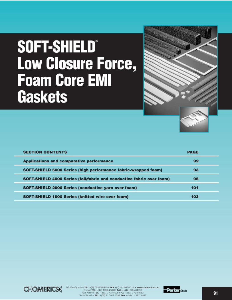
91
SOFT-SHIELD®
Low Closure Force,Foam Core EMIGaskets
SECTION CONTENTS PAGE
Applications and comparative performance 92
SOFT-SHIELD 5000 Series (high performance fabric-wrapped foam) 93
SOFT-SHIELD 4000 Series (foil/fabric and conductive fabric over foam) 98
SOFT-SHIELD 2000 Series (conductive yarn over foam) 101
SOFT-SHIELD 1000 Series (knitted wire over foam) 103
US Headquarters TEL +(1) 781-935-4850 FAX +(1) 781-933-4318 • www.chomerics.comEurope TEL +(44) 1628 404000 FAX +(44) 1628 404090
Asia Pacific TEL +(852) 2 428 8008 FAX +(852) 2 423 8253South America TEL +(55) 11 3917 1099 FAX +(55) 11 3917 0817
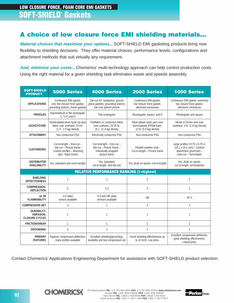
92US Headquarters TEL +(1) 781-935-4850 FAX +(1) 781-933-4318 • www.chomerics.com
Europe TEL +(44) 1628 404000 FAX +(44) 1628 404090Asia Pacific TEL +(852) 2 428 8008 FAX +(852) 2 423 8253
South America TEL +(55) 11 3917 1099 FAX +(55) 11 3917 0817
SOFT-SHIELD® Gaskets
A choice of low closure force EMI shielding materials…Material choices that maximize your options... SOFT-SHIELD EMI gasketing products bring new
flexibility to shielding decisions. They offer material choices, performance levels, configurations and
attachment methods that suit virtually any requirement.
And, minimize your costs... Chomerics’ multi-technology approach can help control production costs.
Using the right material for a given shielding task eliminates waste and speeds assembly.
Contact Chomerics’ Applications Engineering Department for assistance with SOFT-SHIELD product selection.
SOFT-SHIELD 5000 Series 4000 Series 2000 Series 1000 SeriesPRODUCT
Continuous EMI gasket, Die-cut I/O, backplane, ground Continuous EMI gasket, Continuous EMI gasket, extremely APPLICATIONS very low closure force gasket, plane gaskets, grounding buttons, low closure force gasket, low closure force gasket,
grounding buttons, frame gaskets low cost spliced picture electronic enclosures electronic enclosures
PROFILES Asymmetrical or flat rectangular, Flat rectangular Rectangular, square, and D Rectangular and squareC, V, P, and D
Nickel-plated-silver nylon rip-stop Foil/fabric or conductive fabric Silver-plated nylon yarn over Monel or Ferrex wire overJACKET/CORE fabric over urethane, 3-5 lb. over urethane, 20-25 lb. thermoplastic EPDM foam, urethane, 4 lb. (1.8 kg) density
(1.4 - 2.3 kg) density (9.1 -11.4 kg) density 12 lb. (5.5 kg) density
ATTACHMENT Non-conductive PSA Electrically conductive PSA Non-conductive PSA Non-conductive PSA
Cut-to-length – Kiss-cut – Cut-to-length – Kiss-cut – Large profiles >0.75 x 0.75 in.Die-cut – Picture frame – Die-cut – Picture frame – Parallel weather seal– (19.1 x 19.1 mm) – Custom
CUSTOMIZING Custom profiles – Mounting Individually wrapped Cut-to-length – Picture frame attachment (push-pin) – clips– Rigid inserts picture frame Auto-cut – Termination
DISTRIBUTOR Yes, (standard and cut-to-length) Yes, (standard, Yes, (bulk on spools, cut-to-length) Yes, (bulk on spools,AVAILABILITY cut-to-length, and die-cut) cut-to-length, terminations)
RELATIVE PERFORMANCE RANKING (1=highest)SHIELDING 1 1 2 2
EFFECTIVENESS
COMPRESSION- 2 1-3 3 1DEFLECTION
UL 94 V-0 rated V-0 and HB rated HB HF-1FLAMMABILITY version available versions available
COMPRESSION SET 3 1 2 3
DURABILITY, ABRASION, 1 1 1 1
CLOSURE CYCLES
FRICTION/SHEAR 1 1 2 2
GROUNDING 2 1 2 1
PRIMARY Superior compression-deflection, Excellent shielding/grounding, Good shielding effectiveness up Excellent compression-deflection,
FEATURES many profiles available durability and low compression set to 10 GHz. Low price. good shielding effectiveness.Lowest price.
LOW CLOSURE FORCE, FOAM CORE EMI GASKETS
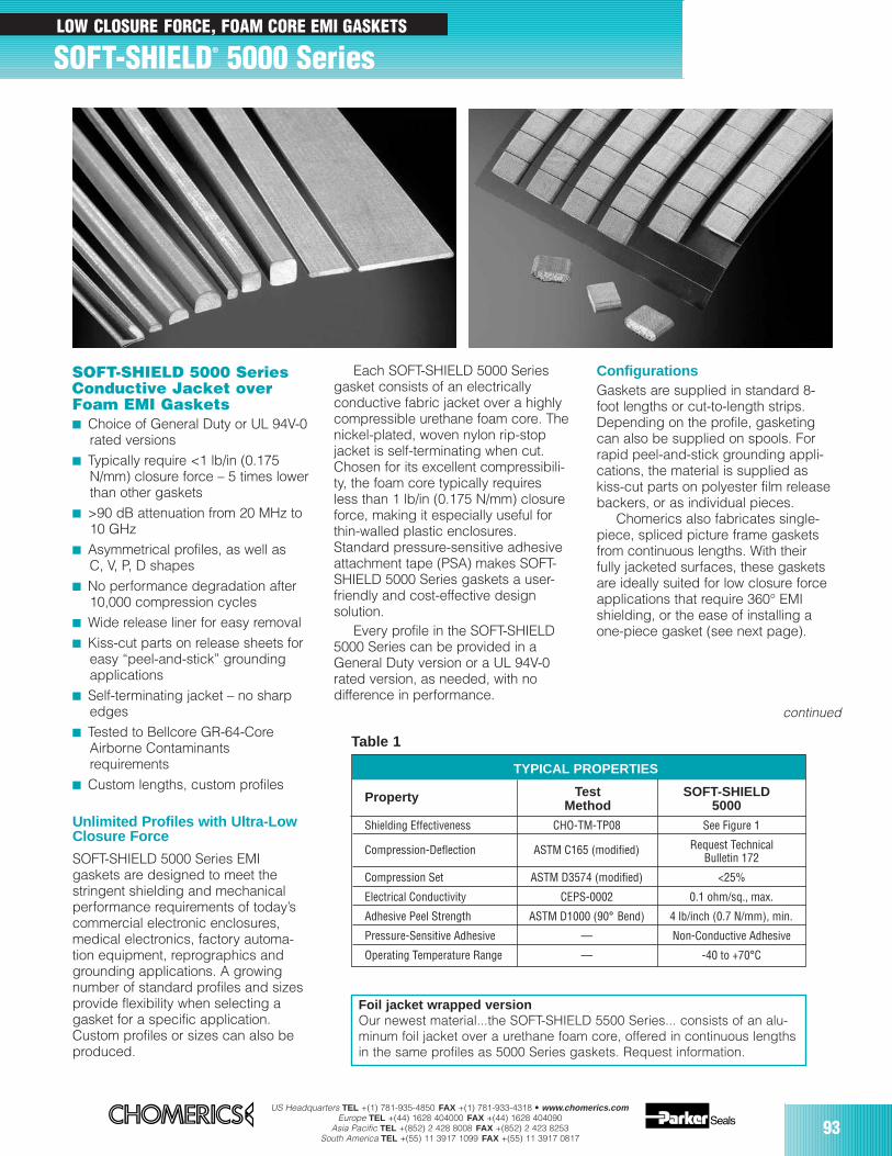
US Headquarters TEL +(1) 781-935-4850 FAX +(1) 781-933-4318 • www.chomerics.comEurope TEL +(44) 1628 404000 FAX +(44) 1628 404090
Asia Pacific TEL +(852) 2 428 8008 FAX +(852) 2 423 8253South America TEL +(55) 11 3917 1099 FAX +(55) 11 3917 0817
93
continued
Unlimited Profiles with Ultra-LowClosure Force
SOFT-SHIELD 5000 Series EMI gaskets are designed to meet thestringent shielding and mechanicalperformance requirements of today’scommercial electronic enclosures,medical electronics, factory automa-tion equipment, reprographics andgrounding applications. A growingnumber of standard profiles and sizesprovide flexibility when selecting agasket for a specific application.Custom profiles or sizes can also beproduced.
SOFT-SHIELD 5000 SeriesConductive Jacket overFoam EMI Gaskets Choice of General Duty or UL 94V-0
rated versions Typically require <1 lb/in (0.175
N/mm) closure force – 5 times lowerthan other gaskets
>90 dB attenuation from 20 MHz to 10 GHz
Asymmetrical profiles, as well as C, V, P, D shapes
No performance degradation after 10,000 compression cycles
Wide release liner for easy removal Kiss-cut parts on release sheets for
easy “peel-and-stick” grounding applications
Self-terminating jacket – no sharp edges
Tested to Bellcore GR-64-Core Airborne Contaminants requirements
Custom lengths, custom profiles
SOFT-SHIELD® 5000 Series
Each SOFT-SHIELD 5000 Seriesgasket consists of an electrically conductive fabric jacket over a highlycompressible urethane foam core. Thenickel-plated, woven nylon rip-stopjacket is self-terminating when cut.Chosen for its excellent compressibili-ty, the foam core typically requiresless than 1 lb/in (0.175 N/mm) closureforce, making it especially useful forthin-walled plastic enclosures.Standard pressure-sensitive adhesiveattachment tape (PSA) makes SOFT-SHIELD 5000 Series gaskets a user-friendly and cost-effective designsolution.
Every profile in the SOFT-SHIELD5000 Series can be provided in aGeneral Duty version or a UL 94V-0rated version, as needed, with no difference in performance.
Table 1
Test SOFT-SHIELDPropertyMethod 5000
Shielding Effectiveness CHO-TM-TP08 See Figure 1
Compression-Deflection ASTM C165 (modified) Request TechnicalBulletin 172
Compression Set ASTM D3574 (modified) <25%
Electrical Conductivity CEPS-0002 0.1 ohm/sq., max.
Adhesive Peel Strength ASTM D1000 (90° Bend) 4 lb/inch (0.7 N/mm), min.
Pressure-Sensitive Adhesive — Non-Conductive Adhesive
Operating Temperature Range — -40 to +70°C
ConfigurationsGaskets are supplied in standard 8-foot lengths or cut-to-length strips.Depending on the profile, gasketingcan also be supplied on spools. Forrapid peel-and-stick grounding appli-cations, the material is supplied askiss-cut parts on polyester film releasebackers, or as individual pieces.
Chomerics also fabricates single-piece, spliced picture frame gasketsfrom continuous lengths. With theirfully jacketed surfaces, these gasketsare ideally suited for low closure forceapplications that require 360° EMIshielding, or the ease of installing aone-piece gasket (see next page).
TYPICAL PROPERTIES
LOW CLOSURE FORCE, FOAM CORE EMI GASKETS
Foil jacket wrapped versionOur newest material...the SOFT-SHIELD 5500 Series... consists of an alu-minum foil jacket over a urethane foam core, offered in continuous lengthsin the same profiles as 5000 Series gaskets. Request information.
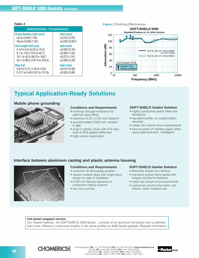
94US Headquarters TEL +(1) 781-935-4850 FAX +(1) 781-933-4318 • www.chomerics.com
Europe TEL +(44) 1628 404000 FAX +(44) 1628 404090Asia Pacific TEL +(852) 2 428 8008 FAX +(852) 2 423 8253
South America TEL +(55) 11 3917 1099 FAX +(55) 11 3917 0817
SOFT-SHIELD® 5000 Gaskets continued
Typical Application-Ready Solutions
Conditions and Requirements• minimize through-resistance for
optimum grounding• maximum 0.25 x 0.25 inch footprint• accommodate 0.040 inch variation ` in gap• snap-in plastic cover with 2 lb max.
load at 50% gasket deflection• high volume application
Mobile phone groundingSOFT-SHIELD Gasket Solution• highly conductive jacket offers low
resistance• standard profile, no customization
required• meets low closure force requirements• kiss-cut parts on release paper allow
quick peel-and-stick installation
Interface between aluminum casting and plastic antenna housing
Conditions and Requirements• overcome 45 dB leakage problem• replace multiple strips with single-piece
design for ease of installation• 0.030 inch flatness tolerance on
component mating surfaces• low cost a priority
SOFT-SHIELD Gasket Solution• effectively shields the interface• one-piece picture frame gasket with
integral notches for fasteners • meets low closure force requirements • customized solution that meets cost
criteria—lower installed cost
DIMENSIONAL TOLERANCES
Cross Section inch (mm) inch (mm)Up to 0.040 (1.02) ±0.010 (0.25)Above 0.040 (1.02) ±0.020 (0.051)
Cut Length inch (cm) inch (mm)0.10 to 6.0 (0.25 to 15.2) ±0.030 (0.76)6.1 to 18.0 (15.5 to 45.7) ±0.060 (1.52)18.1 to 42.0 (46.0 to 106.7 ±0.075 (1.91)42.1 to 96.0 (107.0 to 243.8) ±0.090 (2.29)
Kiss-Cut inch (mm)0.04 to 0.12 (1.02 to 3.05) ±0.015 (0.38)0.121 to 0.40 (3.07 to 10.16) ±0.035 (0.89)
Table 2
120
100
80
60
40
20
010 100 1000 10000
Test Procedure TP-08
Att
enu
atio
n (
dB
)
SOFT-SHIELD 5000Standard Product vs. UL 94V-0 Version
Dynamic TestRange Limitation
Part No. 82-122-74012-09600 (UL 94V-0 rated)
Part No. 82-121-74012-09600
Frequency (MHz)
Figure 1 Shielding Effectiveness
Foil jacket wrapped versionOur newest material...the SOFT-SHIELD 5500 Series... consists of an aluminum foil jacket over a urethanefoam core, offered in continuous lengths in the same profiles as 5000 Series gaskets. Request information.

US Headquarters TEL +(1) 781-935-4850 FAX +(1) 781-933-4318 • www.chomerics.comEurope TEL +(44) 1628 404000 FAX +(44) 1628 404090
Asia Pacific TEL +(852) 2 428 8008 FAX +(852) 2 423 8253South America TEL +(55) 11 3917 1099 FAX +(55) 11 3917 0817
95
8 2 – A B C – X X X X X – Y Y Y Y Y
DesignatesSOFT-SHIELD 5000 EMI gaskets
AJacket Type
1 Nickel-plated nylon rip-stop fabric2 Other (to be assigned)
BPSA Tape Backing
1 No PSA tape2 PSA tape
CGasket Service Rating
1 General duty (urethane foam core)2 UL 94V-0 rating*
Gasket profile (see below) Length in inches x 100ex., 09600 = 8 ft. (std)
ORDERING INFORMATIONReferring to Tables 3-6, use the part number shown here to order SOFT-SHIELD 5000 Series gasketing.
RECTANGULAR STRIPSProfile Number Height Width
74039 0.020 (0.50) 0.157 (4.00)
74020 0.039 (1.00) 0.157 (4.00)
74003 0.039 (1.00) 0.197 (5.00)
74038 0.039 (1.00) 0.275 (7.00)
74004 0.039 (1.00) 0.394 (10.00)
74035 0.059 (1.50) 0.157 (4.00)
74040 0.062 (1.60) 0.200 (5.00)
74034 0.071 (1.80) 0.551 (14.00)
74002 0.079 (2.00) 0.157 (4.00)
74005 0.079 (2.00) 0.275 (7.00)
74025 0.079 (2.00) 0.394 (10.00)
74049 0.079 (2.00) 0.827 (21.00)
74018 0.118 (3.00) 0.118 (3.00)
74048 0.118 (3.00) 0.157 (4.00)
74023 0.125 (3.18) 0.250 (6.35)
74000 0.125 (3.18) 0.375 (9.53)
74012 0.125 (3.18) 0.500 (12.70)
74001 0.125 (3.18) 0.800 (20.32)
74026 0.125 (3.18) 1.850 (47.00)
74015 0.130 (3.30) 0.190 (4.83)
74017 0.200 (5.08) 0.200 (5.08)
74054 0.200 (5.08) 0.300 (7.60)
74022 0.236 (6.00) 0.236 (6.00)
74016 0.250 (6.35) 0.375 (9.53)
74014 0.250 (6.35) 0.500 (12.70)
74024 0.375 (9.53) 0.375 (9.53)
74021 0.375 (9.53) 0.500 (12.70)
74028 0.500 (12.70) 0.500 (12.70)
W
H
Table 374039
APPROX. ACTUAL SIZE
74020 74003 74038 74004
74035 74040 74002 74005
74025 74034 74049
74048 74023 74000 74012
74001 74026
74015 74054 74016
74014 74021
NOTE: Dimensions shown do not include PSA thickness (0.005 inch typically). Actual size shown with PSA strip.
All SOFT-SHIELD 5000 Series profiles can be supplied in eitherGeneral Duty or UL 94V-0 rated versions.
(mm dimensions in parentheses)
Compression-deflection information is available for SOFT-SHIELD 5000 Series profiles. Request Technical Bulletin 172.
74018
74017
74024 74028
74022
continued
Foil jacket wrapped versionOur newest material...the SOFT-SHIELD 5500 Series... consistsof an aluminum foil jacket over a urethane foam core, offered incontinuous lengths in the same profiles as 5000 Series gaskets.Request information.
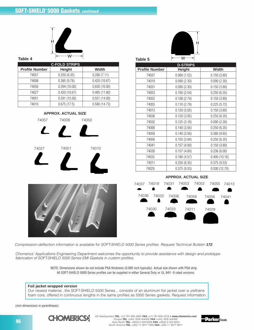
96US Headquarters TEL +(1) 781-935-4850 FAX +(1) 781-933-4318 • www.chomerics.com
Europe TEL +(44) 1628 404000 FAX +(44) 1628 404090Asia Pacific TEL +(852) 2 428 8008 FAX +(852) 2 423 8253
South America TEL +(55) 11 3917 1099 FAX +(55) 11 3917 0817
74010
SOFT-SHIELD® 5000 Gaskets continued
Chomerics’ Applications Engineering Department welcomes the opportunity to provide assistance with design and prototype fabrication of SOFT-SHIELD 5000 Series EMI Gaskets in custom profiles.
C-FOLD STRIPSProfile Number Height Width
74057 0.250 (6.35) 0.280 (7.11)
74008 0.385 (9.78) 0.420 (10.67)
74050 0.394 (10.00) 0.630 (16.00)
74027 0.420 (10.67) 0.465 (11.80)
74051 0.591 (15.00) 0.551 (14.00)
74010 0.675 (17.5) 0.580 (14.73)
H
WTable 4
APPROX. ACTUAL SIZE
74008
74027
Compression-deflection information is available for SOFT-SHIELD 5000 Series profiles. Request Technical Bulletin 172.
NOTE: Dimensions shown do not include PSA thickness (0.005 inch typically). Actual size shown with PSA strip.All SOFT-SHIELD 5000 Series profiles can be supplied in either General Duty or UL 94V -0 rated versions.
W
H
Table 5D-STRIPS
Profile Number Height Width
74037 0.060 (1.52) 0.150 (3.80)
74019 0.090 (2.30) 0.090 (2.30)
74031 0.090 (2.30) 0.150 (3.80)
74053 0.100 (2.54) 0.250 (6.35)
74052 0.108 (2.74) 0.150 (3.80)
74055 0.110 (2.79) 0.225 (5.72)
74013 0.120 (3.05) 0.150 (3.80)
74036 0.120 (3.05) 0.250 (6.35)
74032 0.125 (3.18) 0.090 (2.30)
74006 0.140 (3.56) 0.250 (6.35)
74058 0.140 (3.56) 0.380 (9.65)
74056 0.155 (3.94) 0.250 (6.35)
74041 0.157 (4.00) 0.150 (3.80)
74030 0.157 (4.00) 0.236 (6.00)
74033 0.180 (4.57) 0.400 (10.16)
74011 0.250 (6.35) 0.375 (9.53)
74029 0.375 (9.53) 0.500 (12.70)
APPROX. ACTUAL SIZE
74019
74032
74037 74031 74052 7401374055
74030
74053
74036 74006
7401174033 74029
74057 74050
74051
(mm dimensions in parentheses)
74058 74056 74041
Foil jacket wrapped versionOur newest material...the SOFT-SHIELD 5500 Series... consists of an aluminum foil jacket over a urethanefoam core, offered in continuous lengths in the same profiles as 5000 Series gaskets. Request information.
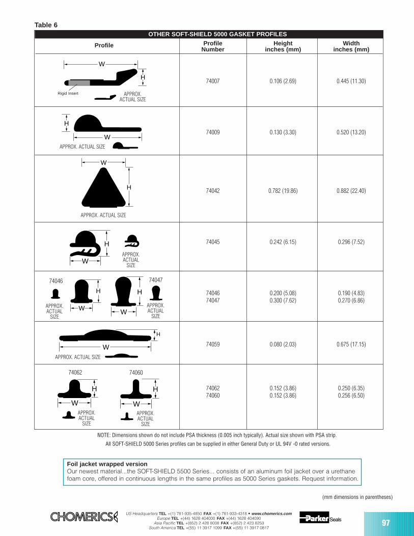
US Headquarters TEL +(1) 781-935-4850 FAX +(1) 781-933-4318 • www.chomerics.comEurope TEL +(44) 1628 404000 FAX +(44) 1628 404090
Asia Pacific TEL +(852) 2 428 8008 FAX +(852) 2 423 8253South America TEL +(55) 11 3917 1099 FAX +(55) 11 3917 0817
97
W
H
KNIFE-EDGE STRIPS
Profile Profile Height WidthNumber inches (mm) inches (mm)
74007 0.106 (2.69) 0.445 (11.30)
74009 0.130 (3.30) 0.520 (13.20)
74042 0.782 (19.86) 0.882 (22.40)
74045 0.242 (6.15) 0.296 (7.52)
74046 0.200 (5.08) 0.190 (4.83)74047 0.300 (7.62) 0.270 (6.86)
74059 0.080 (2.03) 0.675 (17.15)
74062 0.152 (3.86) 0.250 (6.35)74060 0.152 (3.86) 0.256 (6.50)
W
H
Table 6
Rigid Insert
W
H
NOTE: Dimensions shown do not include PSA thickness (0.005 inch typically). Actual size shown with PSA strip.
All SOFT-SHIELD 5000 Series profiles can be supplied in either General Duty or UL 94V -0 rated versions.
(mm dimensions in parentheses)
APPROX.ACTUAL SIZE
APPROX. ACTUAL SIZE
H
WAPPROX.ACTUAL
SIZE
H
W
74046
APPROX.ACTUAL
SIZE
H
W
74047
H
W
H
W
74062
H
W
74060
OTHER SOFT-SHIELD 5000 GASKET PROFILES
APPROX. ACTUAL SIZE
APPROX.ACTUAL
SIZE
APPROX. ACTUAL SIZE
APPROX.ACTUAL
SIZE
APPROX.ACTUAL
SIZE
Foil jacket wrapped versionOur newest material...the SOFT-SHIELD 5500 Series... consists of an aluminum foil jacket over a urethanefoam core, offered in continuous lengths in the same profiles as 5000 Series gaskets. Request information.
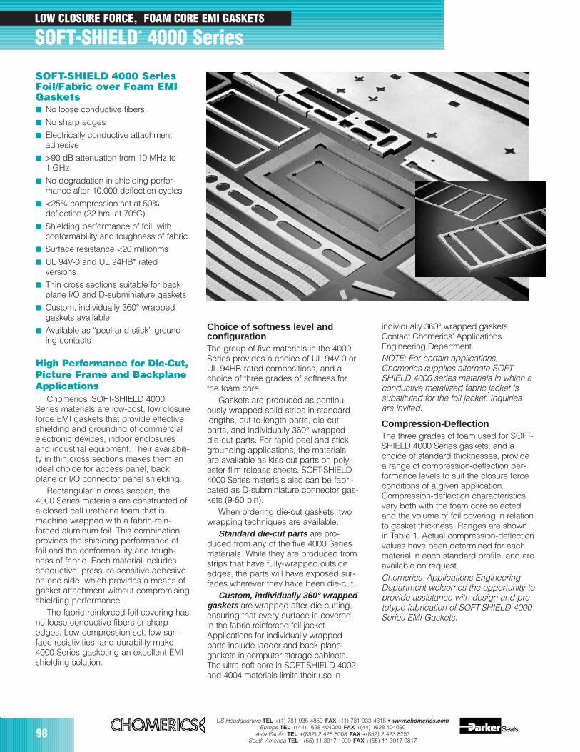
98US Headquarters TEL +(1) 781-935-4850 FAX +(1) 781-933-4318 • www.chomerics.com
Europe TEL +(44) 1628 404000 FAX +(44) 1628 404090Asia Pacific TEL +(852) 2 428 8008 FAX +(852) 2 423 8253
South America TEL +(55) 11 3917 1099 FAX +(55) 11 3917 0817
LOW CLOSURE FORCE, FOAM CORE EMI GASKETS
SOFT-SHIELD® 4000 Series
SOFT-SHIELD 4000 SeriesFoil/Fabric over Foam EMIGaskets No loose conductive fibers
No sharp edges
Electrically conductive attachment adhesive
>90 dB attenuation from 10 MHz to 1 GHz
No degradation in shielding perfor-mance after 10,000 deflection cycles
<25% compression set at 50% deflection (22 hrs. at 70°C)
Shielding performance of foil, with conformability and toughness of fabric
Surface resistance <20 milliohms
UL 94V-0 and UL 94HB* rated versions
Thin cross sections suitable for back plane I/O and D-subminiature gaskets
Custom, individually 360° wrapped gaskets available
Available as “peel-and-stick” ground-ing contacts
High Performance for Die-Cut,Picture Frame and BackplaneApplications
Chomerics’ SOFT-SHIELD 4000Series materials are low-cost, low closureforce EMI gaskets that provide effectiveshielding and grounding of commercialelectronic devices, indoor enclosuresand industrial equipment. Their availabili-ty in thin cross sections makes them anideal choice for access panel, backplane or I/O connector panel shielding.
Rectangular in cross section, the4000 Series materials are constructed ofa closed cell urethane foam that ismachine wrapped with a fabric-rein-forced aluminum foil. This combinationprovides the shielding performance offoil and the conformability and tough-ness of fabric. Each material includesconductive, pressure-sensitive adhesiveon one side, which provides a means ofgasket attachment without compromisingshielding performance.
The fabric-reinforced foil covering hasno loose conductive fibers or sharpedges. Low compression set, low sur-face resistivities, and durability make4000 Series gasketing an excellent EMIshielding solution.
Choice of softness level and configurationThe group of five materials in the 4000Series provides a choice of UL 94V-0 orUL 94HB rated compositions, and achoice of three grades of softness forthe foam core.
Gaskets are produced as continu-ously wrapped solid strips in standardlengths, cut-to-length parts, die-cutparts, and individually 360° wrappeddie-cut parts. For rapid peel and stickgrounding applications, the materialsare available as kiss-cut parts on poly-ester film release sheets. SOFT-SHIELD4000 Series materials also can be fabri-cated as D-subminiature connector gas-kets (9-50 pin).
When ordering die-cut gaskets, twowrapping techniques are available:
Standard die-cut parts are pro-duced from any of the five 4000 Seriesmaterials. While they are produced fromstrips that have fully-wrapped outsideedges, the parts will have exposed sur-faces wherever they have been die-cut.
Custom, individually 360° wrappedgaskets are wrapped after die cutting,ensuring that every surface is coveredin the fabric-reinforced foil jacket.Applications for individually wrappedparts include ladder and back planegaskets in computer storage cabinets.The ultra-soft core in SOFT-SHIELD 4002and 4004 materials limits their use in
individually 360° wrapped gaskets.Contact Chomerics’ ApplicationsEngineering Department. NOTE: For certain applications,Chomerics supplies alternate SOFT-SHIELD 4000 series materials in which aconductive metallized fabric jacket issubstituted for the foil jacket. Inquiriesare invited.
Compression-DeflectionThe three grades of foam used for SOFT-SHIELD 4000 Series gaskets, and achoice of standard thicknesses, providea range of compression-deflection per-formance levels to suit the closure forceconditions of a given application.Compression-deflection characteristicsvary both with the foam core selectedand the volume of foil covering in relationto gasket thickness. Ranges are shownin Table 1. Actual compression-deflectionvalues have been determined for eachmaterial in each standard profile, and areavailable on request.Chomerics’ Applications EngineeringDepartment welcomes the opportunity toprovide assistance with design and pro-totype fabrication of SOFT-SHIELD 4000Series EMI Gaskets.
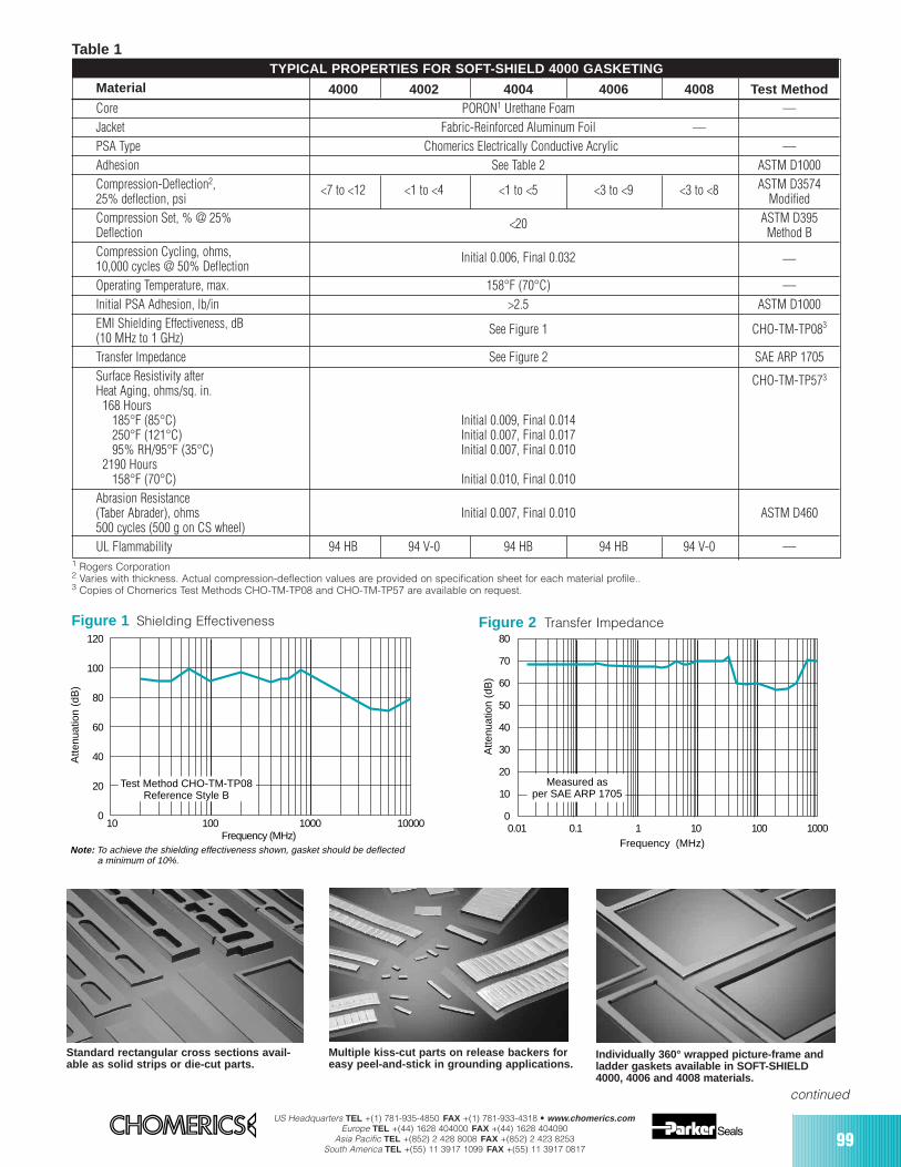
US Headquarters TEL +(1) 781-935-4850 FAX +(1) 781-933-4318 • www.chomerics.comEurope TEL +(44) 1628 404000 FAX +(44) 1628 404090
Asia Pacific TEL +(852) 2 428 8008 FAX +(852) 2 423 8253South America TEL +(55) 11 3917 1099 FAX +(55) 11 3917 0817
99
Material 4000 4002 4004 4006 4008 Test MethodCore PORON1 Urethane Foam —Jacket Fabric-Reinforced Aluminum Foil —PSA Type Chomerics Electrically Conductive Acrylic —Adhesion See Table 2 ASTM D1000Compression-Deflection2, <7 to <12 <1 to <4 <1 to <5 <3 to <9 <3 to <8 ASTM D357425% deflection, psi ModifiedCompression Set, % @ 25% <20 ASTM D395 Deflection Method B Compression Cycling, ohms, 10,000 cycles @ 50% Deflection
Initial 0.006, Final 0.032 —
Operating Temperature, max. 158°F (70°C) —Initial PSA Adhesion, lb/in >2.5 ASTM D1000EMI Shielding Effectiveness, dB (10 MHz to 1 GHz)
See Figure 1 CHO-TM-TP083
Transfer Impedance See Figure 2 SAE ARP 1705Surface Resistivity after CHO-TM-TP573
Heat Aging, ohms/sq. in.168 Hours
185°F (85°C) Initial 0.009, Final 0.014250°F (121°C) Initial 0.007, Final 0.01795% RH/95°F (35°C) Initial 0.007, Final 0.010
2190 Hours158°F (70°C) Initial 0.010, Final 0.010
Abrasion Resistance(Taber Abrader), ohms Initial 0.007, Final 0.010 ASTM D460500 cycles (500 g on CS wheel)UL Flammability 94 HB 94 V-0 94 HB 94 HB 94 V-0 —
120
100
80
60
40
20
010 100 1000 10000
Atte
nuat
ion
(dB
)
Frequency (MHz)
Test Method CHO-TM-TP08Reference Style B
Note: To achieve the shielding effectiveness shown, gasket should be deflecteda minimum of 10%.
Figure 1 Shielding Effectiveness
Table 1TYPICAL PROPERTIES FOR SOFT-SHIELD 4000 GASKETING
1 Rogers Corporation2 Varies with thickness. Actual compression-deflection values are provided on specification sheet for each material profile..3 Copies of Chomerics Test Methods CHO-TM-TP08 and CHO-TM-TP57 are available on request.
continued
80
70
60
50
40
30
20
10
00.01 0.1 1 10 100 1000
Frequency (MHz)
Atte
nuat
ion
(dB
)
Measured asper SAE ARP 1705
Figure 2 Transfer Impedance
Standard rectangular cross sections avail-able as solid strips or die-cut parts.
Multiple kiss-cut parts on release backers foreasy peel-and-stick in grounding applications.
Individually 360° wrapped picture-frame andladder gaskets available in SOFT-SHIELD4000, 4006 and 4008 materials.
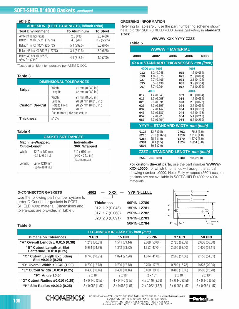
100US Headquarters TEL +(1) 781-935-4850 FAX +(1) 781-933-4318 • www.chomerics.com
Europe TEL +(44) 1628 404000 FAX +(44) 1628 404090Asia Pacific TEL +(852) 2 428 8008 FAX +(852) 2 423 8253
South America TEL +(55) 11 3917 1099 FAX +(55) 11 3917 0817
GASKET SIZE RANGES
WWWW = MATERIAL
4000 4002 4004 4006 4008
XXX = STANDARD THICKNESSES mm (inch)4000 and 4006 4008
012 1.2 (0.048) 016 1.6 (0.064)019 1.9 (0.075) 023 2.3 (0.091)027 2.7 (0.106) 031 3.1 (0.122)035 3.5 (0.138) 039 3.9 (0.154)067 6.7 (0.264) 017 7.1 (0.279)
4002 4004012 1.2 (0.048) 009 0.9 (0.034)017 1.7 (0.068) 014 1.4 (0.054)023 2.3 (0.091) 020 2.0 (0.077)027 2.7 (0.106) 024 2.4 (0.094)037 3.7 (0.147) 034 3.4 (0.133)047 4.7 (0.187) 044 4.4 (0.173)057 5.7 (0.226) 054 5.4 (0.212)067 6.7 (0.264) 064 6.4 (0.250)
YYYY = STANDARD WIDTH mm (inch)0127 12.7 (0.5) 0762 76.2 (3.0)0210 21.0 (0.825) 1016 101.6 (4.0)0254 25.4 (1.0) 1270 127.0 (5.0)0381 38.1 (1.5) 1524 152.4 (6.0)0508 50.8 (2.0)
ZZZZ = STANDARD LENGTH mm (inch)
2540 254 (10.0) 5080 508 (20.0)
ORDERING INFORMATIONReferring to Tables 3-5, use the part numbering scheme shownhere to order SOFT-SHIELD 4000 Series gasketing in standardsizes :
WWWW-XXX-YYYY-ZZZZTable 5
Strips Width: ±1 mm (0.040 in.)Length: ±2 mm (0.080 in.)
Width: ±1 mm (0.040 in.)Length: ±0.38 mm (0.015 in.)
Custom Die-Cut Hole to Hole: ±0.25 mm (0.010 in.)Angular: ±0.5°Datum from a die-cut feature.
Thickness ±10%
DIMENSIONAL TOLERANCES
Machine-Wrapped/ Individually Cut-to-Length 360° Wrapped
Width: 12.7 to 152 mm 610 x 610 mm(0.5 to 6.0 in.) (24.0 x 24.0 in.)
maximum sizeLength: up to 1219 mm
(up to 48.0 in.)For custom die-cut parts , use the part number WWWW-XXX-L0000, for which Chomerics will assign the actualdrawing number L0000. Note: Fully-wrapped (360°) customgaskets are not available in SOFT-SHIELD 4002 or 4004materials.
Table 3
Table 4
ADHESION* (PEEL STRENGTH), lb/inch (N/m)
Test Environment To Aluminum To SteelAmbient Temperature 2.5 (438) 2.5 (438)Baked 1 hr. @ 350°F (177°C) 4.0 (700) 3.9 (682.5)Baked 1 hr. @ 400°F (204°C) 5.1 (892.5) 5.0 (875)Baked 48 hrs. @ 350°F (177°C) 3.1 (542.5) 3.0 (525)Baked 48 hrs. @ 165°F, 4.1 (717.5) 4.0 (700)95% RH (74°C)
*Tested at ambient temperature per ASTM D1000.
Table 2
SOFT-SHIELD® 4000 Gaskets continued
Table 6
D-CONNECTOR GASKETS inch (mm)Dimension Tolerances 9 PIN 15 PIN 25 PIN 37 PIN 50 PIN
“A” Overall Length ± 0.015 (0.38) 1.213 (30.81) 1.541 (39.14) 2.088 (53.04) 2.720 (69.09) 2.630 (66.80)“B” Cutout Length at Slot 0.984 (24.99) 1.312 (33.32) 1.852 (47.04) 2.500 (63.50) 2.406 (61.11)Centerline ±0.010 (0.25)
“C” Cutout Length Excluding 0.746 (18.95) 1.074 (27.28) 1.614 (41.00) 2.266 (57.56) 2.158 (54.81)Slot ±0.010 (0.25)
“D” Overall Width ±0.040 (1.00) 0.700 (17.78) 0.700 (17.78) 0.700 (17.78) 0.700 (17.78) 0.825 (20.96)“E” Cutout Width ±0.010 (0.25) 0.400 (10.16) 0.400 (10.16) 0.400 (10.16) 0.400 (10.16) 0.500 (12.70)
“F” Angle ±0.5° 2 x 10° 2 x 10° 2 x 10° 2 x 10° 2 x 10°“G” Cutout Radius ±0.010 (0.25) 4 x 0.140 (3.56) 4 x 0.140 (3.56) 4 x 0.140 (3.56) 4 x 0.140 (3.56) 4 x 0.140 (3.56)
“H” Slot Radius ±0.010 (0.25) 2 x 0.062 (1.57) 2 x 0.062 (1.57) 2 x 0.062 (1.57) 2 x 0.062 (1.57) 2 x 0.062 (1.57)
4002 — XXX — YYPIN-LLLLL
Thickness 09PIN-L2780012 1.2 (0.048) 15PIN-L2781017 1.7 (0.068) 25PIN-L2782023 2.3 (0.091) 37PIN-L2783
50PIN-L2784
D-CONNECTOR GASKETSUse the following part number system toorder D-Connector gaskets in SOFT-SHIELD 4002 material. Dimensions andtolerances are provided in Table 6.
AB
C
DE
F GH
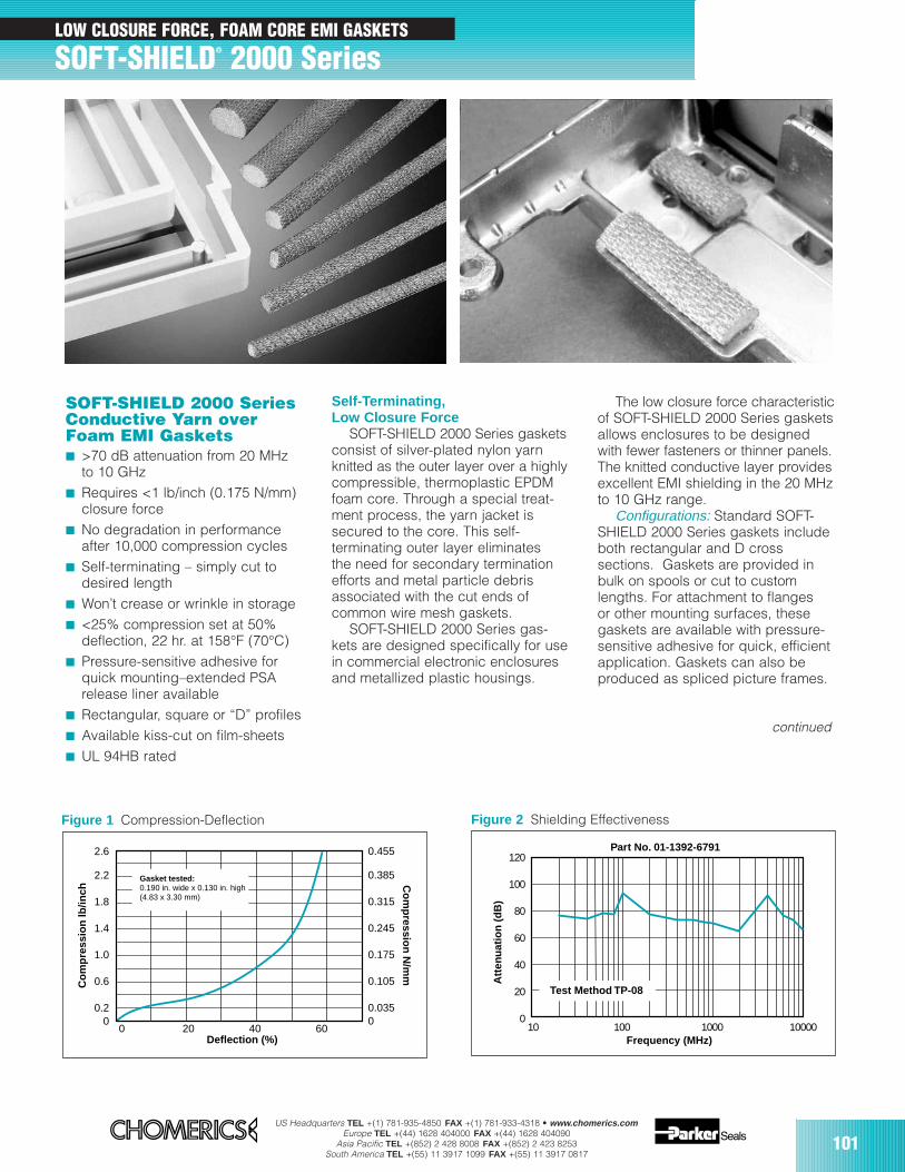
US Headquarters TEL +(1) 781-935-4850 FAX +(1) 781-933-4318 • www.chomerics.comEurope TEL +(44) 1628 404000 FAX +(44) 1628 404090
Asia Pacific TEL +(852) 2 428 8008 FAX +(852) 2 423 8253South America TEL +(55) 11 3917 1099 FAX +(55) 11 3917 0817
101
LOW CLOSURE FORCE, FOAM CORE EMI GASKETS
SOFT-SHIELD® 2000 Series
120
100
80
60
40
20
010 100 1000 10000
Att
enu
atio
n (
dB
)
Frequency (MHz)
Part No. 01-1392-6791
Test Method TP-08
0 20 40 60
2.6
2.2
1.8
1.4
1.0
0.6
0.20
Co
mp
ress
ion
lb/in
ch
Deflection (%)
Gasket tested: 0.190 in. wide x 0.130 in. high (4.83 x 3.30 mm)
Co
mp
ression
N/m
m
0.455
0.385
0.315
0.245
0.175
0.105
0.0350
SOFT-SHIELD 2000 SeriesConductive Yarn overFoam EMI Gaskets >70 dB attenuation from 20 MHz
to 10 GHz Requires <1 lb/inch (0.175 N/mm)
closure force No degradation in performance
after 10,000 compression cycles Self-terminating – simply cut to
desired length Won’t crease or wrinkle in storage <25% compression set at 50%
deflection, 22 hr. at 158°F (70°C) Pressure-sensitive adhesive for
quick mounting–extended PSArelease liner available
Rectangular, square or “D” profiles Available kiss-cut on film-sheets UL 94HB rated
Figure 1 Compression-Deflection Figure 2 Shielding Effectiveness
Self-Terminating, Low Closure Force
SOFT-SHIELD 2000 Series gasketsconsist of silver-plated nylon yarnknitted as the outer layer over a highlycompressible, thermoplastic EPDMfoam core. Through a special treat-ment process, the yarn jacket issecured to the core. This self-terminating outer layer eliminatesthe need for secondary terminationefforts and metal particle debrisassociated with the cut ends ofcommon wire mesh gaskets.
SOFT-SHIELD 2000 Series gas-kets are designed specifically for usein commercial electronic enclosuresand metallized plastic housings.
The low closure force characteristicof SOFT-SHIELD 2000 Series gasketsallows enclosures to be designedwith fewer fasteners or thinner panels.The knitted conductive layer providesexcellent EMI shielding in the 20 MHzto 10 GHz range.
Configurations: Standard SOFT-SHIELD 2000 Series gaskets includeboth rectangular and D crosssections. Gaskets are provided inbulk on spools or cut to customlengths. For attachment to flangesor other mounting surfaces, thesegaskets are available with pressure-sensitive adhesive for quick, efficientapplication. Gaskets can also beproduced as spliced picture frames.
continued
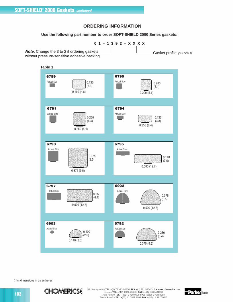
102US Headquarters TEL +(1) 781-935-4850 FAX +(1) 781-933-4318 • www.chomerics.com
Europe TEL +(44) 1628 404000 FAX +(44) 1628 404090Asia Pacific TEL +(852) 2 428 8008 FAX +(852) 2 423 8253
South America TEL +(55) 11 3917 1099 FAX +(55) 11 3917 0817
SOFT-SHIELD® 2000 Gaskets continued
6790
6791
6903
6797
6792
6902
6789
6794
6793 6795
ORDERING INFORMATION
Use the following part number to order SOFT-SHIELD 2000 Series gaskets:
0.190 (4.8)
0.130(3.3)
Actual Size
0.200 (5.1)
0.200(5.1)
Actual Size
0.250 (6.4)
0.250(6.4)
Actual Size
0.250 (6.4)
0.130(3.3)
Actual Size
0.375 (9.5)
0.375(9.5)
Actual Size
0.500 (12.7)
0.140(3.6)
Actual Size
0.500 (12.7)
0.250(6.4)
Actual Size
0.500 (12.7)
0.375(9.5)
Actual Size
0.375 (9.5)
0.250(6.4)
Actual Size
0.140 (3.6)
Actual Size0.100(2.6)
Table 1
0 1 – 1 3 9 2 – X X X X
Note: Change the 3 to 2 if ordering gasketswithout pressure-sensitive adhesive backing.
Gasket profile (Table 1) (See Table 1)
(mm dimensions in parentheses)
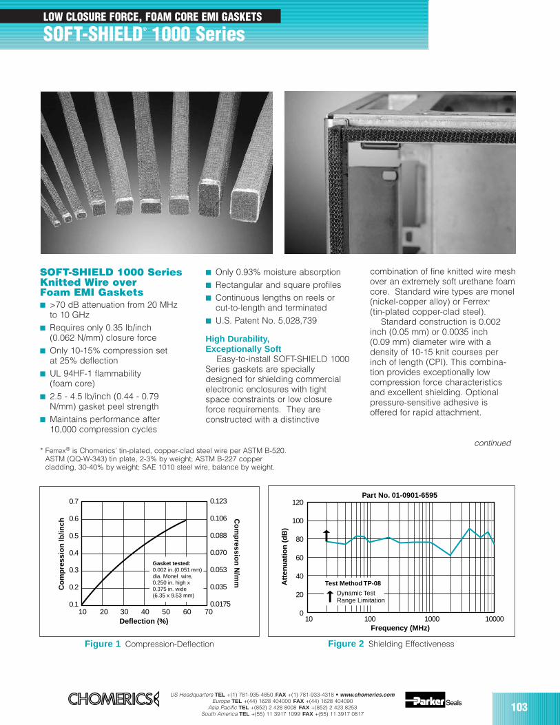
US Headquarters TEL +(1) 781-935-4850 FAX +(1) 781-933-4318 • www.chomerics.comEurope TEL +(44) 1628 404000 FAX +(44) 1628 404090
Asia Pacific TEL +(852) 2 428 8008 FAX +(852) 2 423 8253South America TEL +(55) 11 3917 1099 FAX +(55) 11 3917 0817
103
LOW CLOSURE FORCE, FOAM CORE EMI GASKETS
SOFT-SHIELD® 1000 Series
Only 0.93% moisture absorption Rectangular and square profiles Continuous lengths on reels or
cut-to-length and terminated U.S. Patent No. 5,028,739
High Durability,Exceptionally Soft
Easy-to-install SOFT-SHIELD 1000Series gaskets are speciallydesigned for shielding commercialelectronic enclosures with tightspace constraints or low closureforce requirements. They areconstructed with a distinctive
SOFT-SHIELD 1000 SeriesKnitted Wire overFoam EMI Gaskets >70 dB attenuation from 20 MHz
to 10 GHz Requires only 0.35 lb/inch
(0.062 N/mm) closure force Only 10-15% compression set
at 25% deflection UL 94HF-1 flammability
(foam core) 2.5 - 4.5 lb/inch (0.44 - 0.79
N/mm) gasket peel strength Maintains performance after
10,000 compression cycles
* Ferrex® is Chomerics’ tin-plated, copper-clad steel wire per ASTM B-520.ASTM (QQ-W-343) tin plate, 2-3% by weight; ASTM B-227 coppercladding, 30-40% by weight; SAE 1010 steel wire, balance by weight.
combination of fine knitted wire meshover an extremely soft urethane foamcore. Standard wire types are monel(nickel-copper alloy) or Ferrex*
(tin-plated copper-clad steel).Standard construction is 0.002
inch (0.05 mm) or 0.0035 inch(0.09 mm) diameter wire with adensity of 10-15 knit courses perinch of length (CPI). This combina-tion provides exceptionally lowcompression force characteristicsand excellent shielding. Optionalpressure-sensitive adhesive isoffered for rapid attachment.
0.7
0.6
0.5
0.4
0.3
0.2
0.110 20 30 40 50 60 70
Gasket tested: 0.002 in. (0.051 mm) dia. Monel wire, 0.250 in. high x 0.375 in. wide (6.35 x 9.53 mm)
Co
mp
ress
ion
lb/in
ch
Deflection (%)
0.123
0.106
0.088
0.070
0.053
0.035
0.0175
Co
mp
ression
N/m
m
120
100
80
60
40
20
010 100 1000 10000
Att
enu
atio
n (
dB
)
Frequency (MHz)
Dynamic TestRange Limitation
Part No. 01-0901-6595
Test Method TP-08
Figure 1 Compression-Deflection Figure 2 Shielding Effectiveness
continued
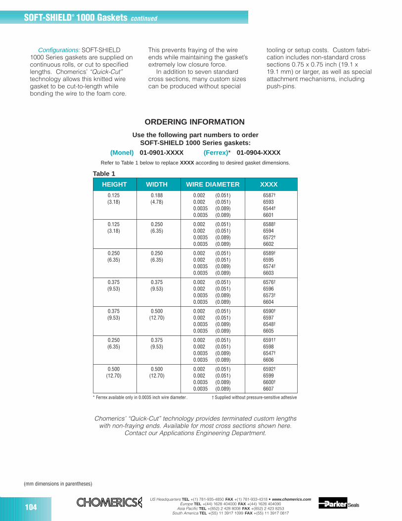
104US Headquarters TEL +(1) 781-935-4850 FAX +(1) 781-933-4318 • www.chomerics.com
Europe TEL +(44) 1628 404000 FAX +(44) 1628 404090Asia Pacific TEL +(852) 2 428 8008 FAX +(852) 2 423 8253
South America TEL +(55) 11 3917 1099 FAX +(55) 11 3917 0817
HEIGHT WIDTH WIRE DIAMETER XXXX
0.125 0.188 0.002 (0.051) 6587†
(3.18) (4.78) 0.002 (0.051) 65930.0035 (0.089) 6544†
0.0035 (0.089) 6601
0.125 0.250 0.002 (0.051) 6588†
(3.18) (6.35) 0.002 (0.051) 65940.0035 (0.089) 6572†
0.0035 (0.089) 6602
0.250 0.250 0.002 (0.051) 6589†
(6.35) (6.35) 0.002 (0.051) 65950.0035 (0.089) 6574†
0.0035 (0.089) 6603
0.375 0.375 0.002 (0.051) 6576†
(9.53) (9.53) 0.002 (0.051) 65960.0035 (0.089) 6573†
0.0035 (0.089) 6604
0.375 0.500 0.002 (0.051) 6590†
(9.53) (12.70) 0.002 (0.051) 65970.0035 (0.089) 6548†
0.0035 (0.089) 6605
0.250 0.375 0.002 (0.051) 6591†
(6.35) (9.53) 0.002 (0.051) 65980.0035 (0.089) 6547†
0.0035 (0.089) 6606
0.500 0.500 0.002 (0.051) 6592†
(12.70) (12.70) 0.002 (0.051) 65990.0035 (0.089) 6600†
0.0035 (0.089) 6607
* Ferrex available only in 0.0035 inch wire diameter . † Supplied without pressure-sensitive adhesive
(mm dimensions in parentheses)
ORDERING INFORMATION
Use the following part numbers to orderSOFT-SHIELD 1000 Series gaskets:
(Monel) 01-0901-XXXX (Ferrex) * 01-0904-XXXXRefer to Table 1 below to replace XXXX according to desired gasket dimensions.
Configurations: SOFT-SHIELD1000 Series gaskets are supplied oncontinuous rolls, or cut to specifiedlengths. Chomerics’ “Quick-Cut”technology allows this knitted wiregasket to be cut-to-length whilebonding the wire to the foam core.
This prevents fraying of the wireends while maintaining the gasket’sextremely low closure force.
In addition to seven standardcross sections, many custom sizescan be produced without special
tooling or setup costs. Custom fabri-cation includes non-standard crosssections 0.75 x 0.75 inch (19.1 x19.1 mm) or larger, as well as specialattachment mechanisms, includingpush-pins.
Table 1
Chomerics’ “Quick-Cut” technology provides terminated custom lengthswith non-fraying ends. Available for most cross sections shown here.
Contact our Applications Engineering Department.
SOFT-SHIELD® 1000 Gaskets continued
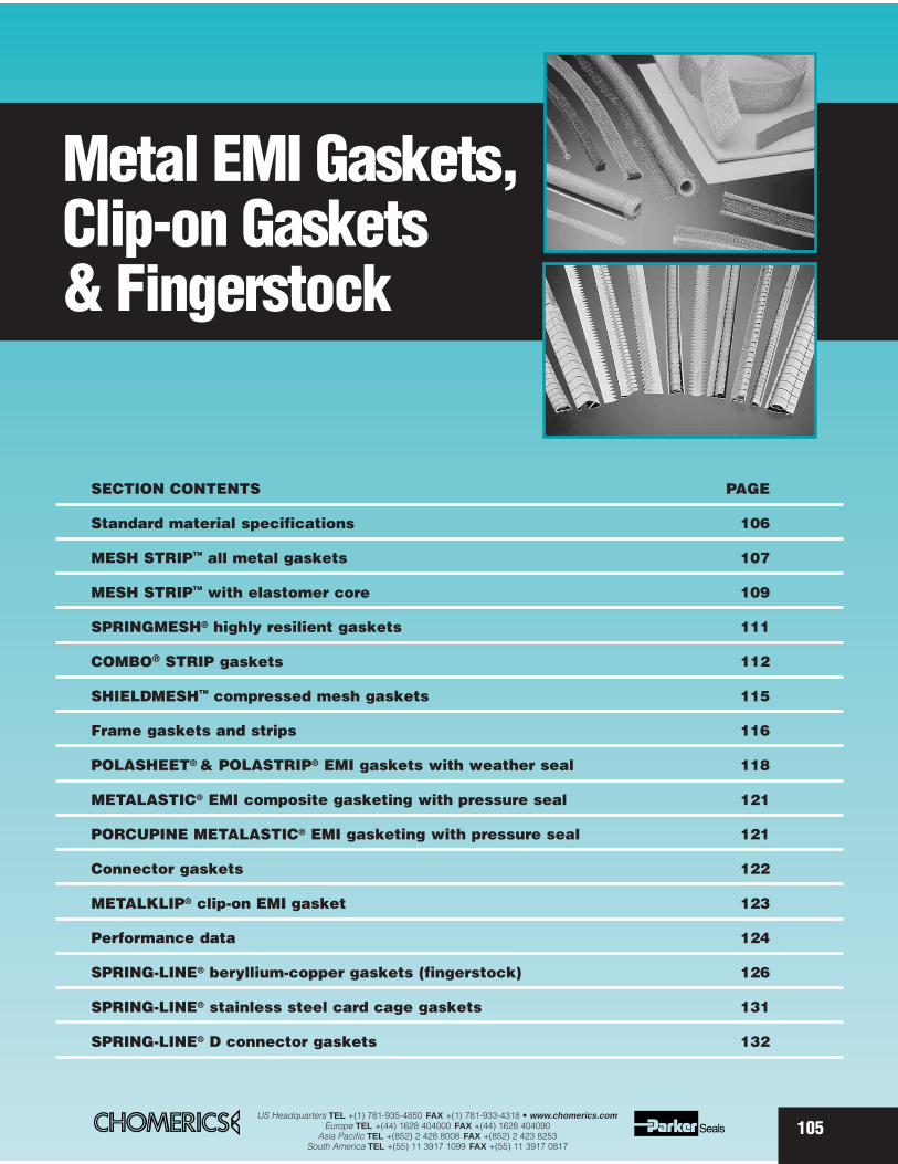
SECTION CONTENTS PAGE
Standard material specifications 106
MESH STRIPTM all metal gaskets 107
MESH STRIPTM with elastomer core 109
SPRINGMESH® highly resilient gaskets 111
COMBO® STRIP gaskets 112
SHIELDMESHTM compressed mesh gaskets 115
Frame gaskets and strips 116
POLASHEET® & POLASTRIP® EMI gaskets with weather seal 118
METALASTIC® EMI composite gasketing with pressure seal 121
PORCUPINE METALASTIC® EMI gasketing with pressure seal 121
Connector gaskets 122
METALKLIP® clip-on EMI gasket 123
Performance data 124
SPRING-LINE® beryllium-copper gaskets (fingerstock) 126
SPRING-LINE® stainless steel card cage gaskets 131
SPRING-LINE® D connector gaskets 132
Metal EMI Gaskets,Clip-on Gaskets& Fingerstock
105US Headquarters TEL +(1) 781-935-4850 FAX +(1) 781-933-4318 • www.chomerics.com
Europe TEL +(44) 1628 404000 FAX +(44) 1628 404090Asia Pacific TEL +(852) 2 428 8008 FAX +(852) 2 423 8253
South America TEL +(55) 11 3917 1099 FAX +(55) 11 3917 0817
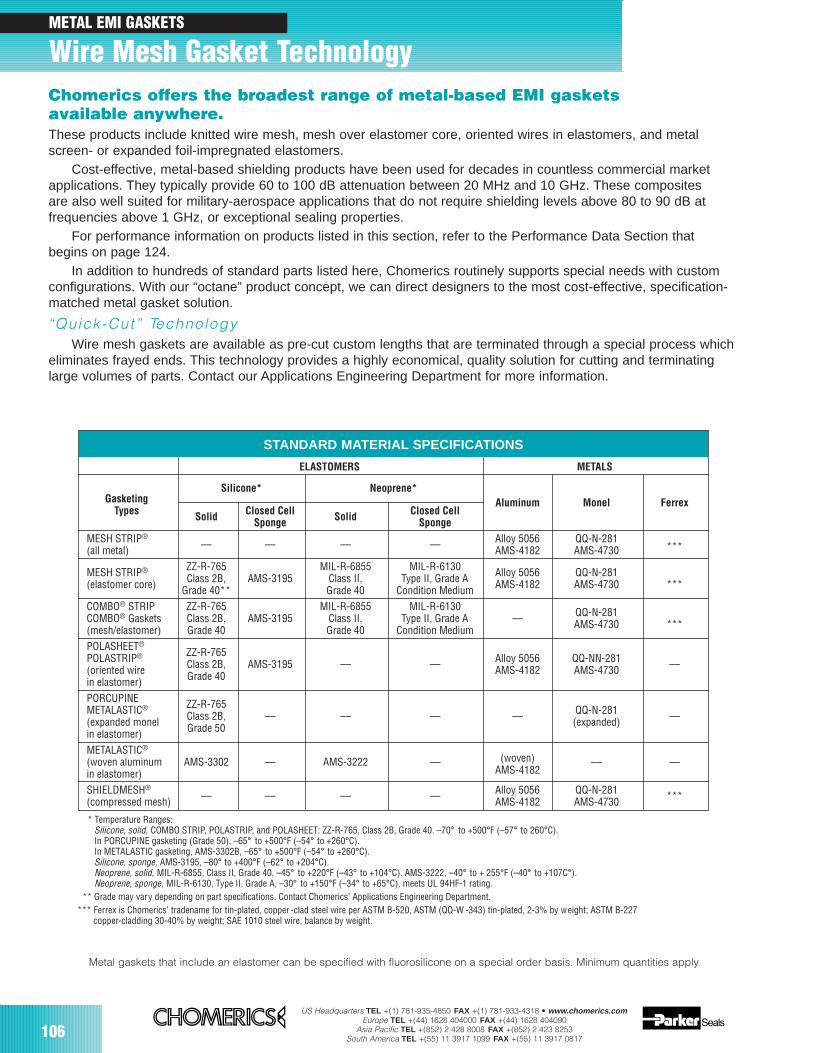
106US Headquarters TEL +(1) 781-935-4850 FAX +(1) 781-933-4318 • www.chomerics.com
Europe TEL +(44) 1628 404000 FAX +(44) 1628 404090Asia Pacific TEL +(852) 2 428 8008 FAX +(852) 2 423 8253
South America TEL +(55) 11 3917 1099 FAX +(55) 11 3917 0817
Chomerics offers the broadest range of metal-based EMI gaskets available anywhere.These products include knitted wire mesh, mesh over elastomer core, oriented wires in elastomers, and metalscreen- or expanded foil-impregnated elastomers.
Cost-effective, metal-based shielding products have been used for decades in countless commercial marketapplications. They typically provide 60 to 100 dB attenuation between 20 MHz and 10 GHz. These composites are also well suited for military-aerospace applications that do not require shielding levels above 80 to 90 dB at frequencies above 1 GHz, or exceptional sealing properties.
For performance information on products listed in this section, refer to the Performance Data Section that begins on page 124.
In addition to hundreds of standard parts listed here, Chomerics routinely supports special needs with customconfigurations. With our “octane” product concept, we can direct designers to the most cost-effective, specification-matched metal gasket solution.
“Quick-Cut” Technology Wire mesh gaskets are available as pre-cut custom lengths that are terminated through a special process which
eliminates frayed ends. This technology provides a highly economical, quality solution for cutting and terminatinglarge volumes of parts. Contact our Applications Engineering Department for more information.
* Temperature Ranges:Silicone, solid, COMBO STRIP, POLASTRIP, and POLASHEET: ZZ-R-765, Class 2B, Grade 40. –70° to +500°F (–57° to 260°C).In PORCUPINE gasketing (Grade 50), –65° to +500°F (–54° to +260°C).In METALASTIC gasketing, AMS-3302B, –65° to +500°F (–54° to +260°C).Silicone, sponge, AMS-3195, –80° to +400°F (–62° to +204°C).Neoprene, solid, MIL-R-6855, Class II, Grade 40, –45° to +220°F (–43° to +104°C). AMS-3222, –40° to + 255°F (–40° to +107C°).Neoprene, sponge, MIL-R-6130, Type II, Grade A, –30° to +150°F (–34° to +65°C), meets UL 94HF-1 rating.
** Grade may vary depending on part specifications. Contact Chomerics’ Applications Engineering Department.*** Ferrex is Chomerics’ tradename for tin-plated, copper -clad steel wire per ASTM B-520, ASTM (QQ-W -343) tin-plated, 2-3% by weight; ASTM B-227
copper-cladding 30-40% by weight; SAE 1010 steel wire, balance by weight.
STANDARD MATERIAL SPECIFICATIONS
ELASTOMERS METALS
Silicone* Neoprene*Gasketing
Types Solid Closed Cell Solid Closed CellAluminum Monel Ferrex
Sponge Sponge
MESH STRIP®–– –– –– –– Alloy 5056 QQ-N-281
***(all metal) AMS-4182 AMS-4730
MESH STRIP® ZZ-R-765 MIL-R-6855 MIL-R-6130 Alloy 5056 QQ-N-281(elastomer core) Class 2B, AMS-3195 Class II, Type II, Grade A AMS-4182 AMS-4730 ***Grade 40** Grade 40 Condition MediumCOMBO® STRIP ZZ-R-765 MIL-R-6855 MIL-R-6130 QQ-N-281COMBO® Gaskets Class 2B, AMS-3195 Class II, Type II, Grade A –– AMS-4730 ***(mesh/elastomer) Grade 40 Grade 40 Condition MediumPOLASHEET®
ZZ-R-765POLASTRIP®Class 2B, AMS-3195 Alloy 5056 QQ-NN-281 ––(oriented wire Grade 40
–– –– AMS-4182 AMS-4730in elastomer)PORCUPINE ZZ-R-765METALASTIC®
Class 2B, QQ-N-281 ––(expanded monel Grade 50–– –– –– –– (expanded)
in elastomer)METALASTIC®
(woven aluminum AMS-3302 –– AMS-3222 –– (woven) –– —in elastomer) AMS-4182
SHIELDMESH®–– –– –– –– Alloy 5056 QQ-N-281 ***(compressed mesh) AMS-4182 AMS-4730
Metal gaskets that include an elastomer can be specified with fluorosilicone on a special order basis. Minimum quantities apply.
Wire Mesh Gasket TechnologyMETAL EMI GASKETS
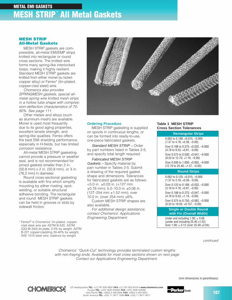
US Headquarters TEL +(1) 781-935-4850 FAX +(1) 781-933-4318 • www.chomerics.comEurope TEL +(44) 1628 404000 FAX +(44) 1628 404090
Asia Pacific TEL +(852) 2 428 8008 FAX +(852) 2 423 8253South America TEL +(55) 11 3917 1099 FAX +(55) 11 3917 0817
107
MESH STRIP™ All Metal Gaskets
MESH STRIPAll-Metal Gaskets
MESH STRIP gaskets are com-pressible, all-metal EMI/EMP stripsknitted into rectangular or roundcross sections. The knitted wireforms many spring-like interlockedloops, making it highly resilient.Standard MESH STRIP gaskets areknitted from either monel (a nickel-copper alloy) or Ferrex* (tin-plated,copper-clad steel) wire.
Chomerics also providesSPRINGMESH gaskets, special all-metal spring wire knitted mesh stripsin a hollow tube shape with compres-sion-deflection characteristics of 70-80%. See page 111.
Other metals and alloys (such as aluminum mesh) are available.Monel is used most frequentlydue to its good aging properties,excellent tensile strength, andspring-like qualities. Ferrex offersthe best EMI shielding performance,especially in H-fields, but has limitedcorrosion resistance.
All-metal MESH STRIP gasketingcannot provide a pressure or weatherseal, and is not recommended forjoined gaskets smaller than 2 in.(50.8 mm) x 2 in. (50.8 mm), or 3 in.(76.2 mm) in diameter.
Round cross-sectional gasketingis available with fins which simplifymounting by either riveting, spot-welding, or suitable structuraladhesive bonding. The rectangularand round MESH STRIP gasketscan be held in grooves or slots bysidewall friction.
Ordering ProcedureMESH STRIP gasketing is supplied
on spools in continuous lengths, orcan be formed into ready-to-use,one-piece fabricated gaskets.
Standard MESH STRIP – Order by part numbers listed in Tables 2-5,and specify total length required.
Fabricated MESH STRIPGaskets – Specify material bypart number in Tables 2-5. Submita drawing of the required gasketshape and dimensions. Tolerancesfor fabricated gaskets are as follows:<5.0 in. ±0.03 in. (<127 mm±0.76 mm); 5.0–10.0 in.±0.06 in. (127–254 mm ±1.52 mm); over10.0 in. (over 254 mm) ±6%.
Custom MESH STRIP shapes arealso available.
For additional design assistance,contact Chomerics’ ApplicationsEngineering Department.
Table 1 MESH STRIPCross Section Tolerances
* Ferrex® is Chomerics’ tin-plated, copper-clad steel wire per ASTM B-520. ASTM (QQ-W-343) tin-plate, 2-3% by weight; ASTMB-227 copper-cladding 30-40% by weight;SAE 1010 steel wire, balance by weight.
Rectangular Strips0.062 to 0.188; +0.015, –0.000(1.57 to 4.78; +0.38, –0.00)Over 0.188 to 0.375; +0.032, –0.000(4.78 to 9.53; +0.81, –0.00)Over 0.375 to 0.500; +0.047, –0.000(9.53 to 12.70; +1.19, –0.00)Over 0.500 to 1.000; +0.062, –0.000(12.70 to 25.40; +1.57, –0.00)
Round Strips
0.062 to 0.125; +0.015, –0.000(1.57 to 3.18; +0.38, –0.00)Over 0.125 to 0.188; +0.032, –0.000(3.18 to 4.78; +0.81, –0.00)Over 0.188 to 0.375; +0.047, –0.000(4.78 to 9.53; +1.19, –0.00)Over 0.375 to 0.750; +0.062, –0.000(9.53 to 19.05; +0.157, –0.00)
Single or Double Roundwith Fin (Overall Width)
Under and including 1.00; ± 0.06(under and including 25.40 ±1.52)Over 1.00; ± 0.12 (over 25.40 ±3.04)
Chomerics’ “Quick-Cut” technology provides terminated custom lengthswith non-fraying ends. Available for most cross sections shown on next page
Contact our Applications Engineering Department.
continued
METAL EMI GASKETS
(mm dimensions in parentheses)
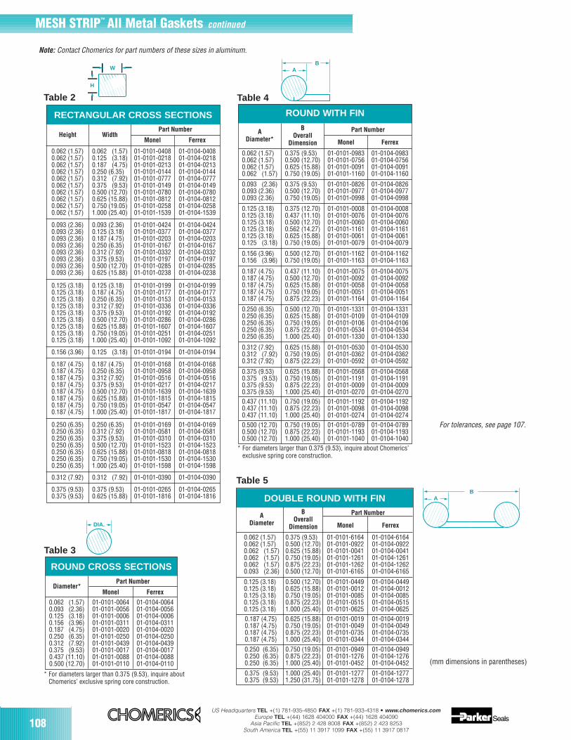
108US Headquarters TEL +(1) 781-935-4850 FAX +(1) 781-933-4318 • www.chomerics.com
Europe TEL +(44) 1628 404000 FAX +(44) 1628 404090Asia Pacific TEL +(852) 2 428 8008 FAX +(852) 2 423 8253
South America TEL +(55) 11 3917 1099 FAX +(55) 11 3917 0817
DOUBLE ROUND WITH FIN
* For diameters larger than 0.375 (9.53), inquire aboutChomerics’ exclusive spring core construction.
* For diameters larger than 0.375 (9.53), inquire about Chomerics’exclusive spring core construction.
Table 3
Table 5
Table 2 Table 4
yyy
zzz||
W
H
BA
yyzz
|||
BA
yyyy
zz|DIA.
Note: Contact Chomerics for part numbers of these sizes in aluminum.
For tolerances, see page 107.
(mm dimensions in parentheses)
RECTANGULAR CROSS SECTIONS
Monel FerrexHeight Width
Part Number
0.062 (1.57)0.062 (1.57)0.062 (1.57)0.062 (1.57)0.062 (1.57)0.062 (1.57)0.062 (1.57)0.062 (1.57)0.062 (1.57)0.062 (1.57)
0.062 (1.57)0.125 (3.18)0.187 (4.75)0.250 (6.35)0.312 (7.92)0.375 (9.53)0.500 (12.70)0.625 (15.88)0.750 (19.05)1.000 (25.40)
01-0101-040801-0101-021801-0101-021301-0101-014401-0101-077701-0101-014901-0101-078001-0101-081201-0101-025801-0101-1539
01-0104-040801-0104-021801-0104-021301-0104-014401-0104-077701-0104-014901-0104-078001-0104-081201-0104-025801-0104-1539
0.093 (2.36)0.093 (2.36)0.093 (2.36)0.093 (2.36)0.093 (2.36)0.093 (2.36)0.093 (2.36)0.093 (2.36)
0.093 (2.36)0.125 (3.18)0.187 (4.75)0.250 (6.35)0.312 (7.92)0.375 (9.53)0.500 (12.70)0.625 (15.88)
01-0101-042401-0101-037701-0101-020301-0101-016701-0101-033201-0101-019701-0101-028501-0101-0238
01-0104-042401-0104-037701-0104-020301-0104-016701-0104-033201-0104-019701-0104-028501-0104-0238
0.125 (3.18)0.125 (3.18)0.125 (3.18)0.125 (3.18)0.125 (3.18)0.125 (3.18)0.125 (3.18)0.125 (3.18)0.125 (3.18)
0.125 (3.18)0.187 (4.75)0.250 (6.35)0.312 (7.92)0.375 (9.53)0.500 (12.70)0.625 (15.88)0.750 (19.05)1.000 (25.40)
01-0101-019901-0101-017701-0101-015301-0101-033601-0101-019201-0101-028601-0101-160701-0101-025101-0101-1092
01-0104-019901-0104-017701-0104-015301-0104-033601-0104-019201-0104-028601-0104-160701-0104-025101-0104-1092
0.156 (3.96) 0.125 (3.18) 01-0101-0194 01-0104-0194
0.187 (4.75)0.187 (4.75)0.187 (4.75)0.187 (4.75)0.187 (4.75)0.187 (4.75)0.187 (4.75)0.187 (4.75)
0.187 (4.75)0.250 (6.35)0.312 (7.92)0.375 (9.53)0.500 (12.70)0.625 (15.88)0.750 (19.05)1.000 (25.40)
01-0101-016801-0101-095801-0101-051601-0101-021701-0101-163901-0101-181501-0101-054701-0101-1817
01-0104-016801-0104-095801-0104-051601-0104-021701-0104-163901-0104-181501-0104-054701-0104-1817
0.250 (6.35)0.250 (6.35)0.250 (6.35)0.250 (6.35)0.250 (6.35)0.250 (6.35)0.250 (6.35)
0.250 (6.35)0.312 (7.92)0.375 (9.53)0.500 (12.70)0.625 (15.88)0.750 (19.05)1.000 (25.40)
01-0101-016901-0101-058101-0101-031001-0101-152301-0101-081801-0101-153001-0101-1598
01-0104-016901-0104-058101-0104-031001-0104-152301-0104-081801-0104-153001-0104-1598
0.312 (7.92) 0.312 (7.92) 01-0101-0390 01-0104-0390
0.375 (9.53)0.375 (9.53)
0.375 (9.53)0.625 (15.88)
01-0101-026501-0101-1816
01-0104-026501-0104-1816
ROUND CROSS SECTIONS
Monel Ferrex
0.062 (1.57)0.093 (2.36)0.125 (3.18)0.156 (3.96)0.187 (4.75)0.250 (6.35)0.312 (7.92)0.375 (9.53)0.437 (11.10)0.500 (12.70)
Diameter*Part Number
01-0101-006401-0101-005601-0101-000601-0101-031101-0101-002001-0101-025001-0101-043901-0101-001701-0101-008801-0101-0110
01-0104-006401-0104-005601-0104-000601-0104-031101-0104-002001-0104-025001-0104-043901-0104-001701-0104-008801-0104-0110
ROUND WITH FIN
Monel Ferrex
0.437 (11.10)0.437 (11.10)0.437 (11.10)
ADiameter*
BOverall
Dimension
Part Number
0.750 (19.05)0.875 (22.23)1.000 (25.40)
0.062 (1.57)0.062 (1.57)0.062 (1.57)0.062 (1.57)
0.375 (9.53)0.500 (12.70)0.625 (15.88)0.750 (19.05)
01-0101-098301-0101-075601-0101-009101-0101-1160
01-0104-098301-0104-075601-0104-009101-0104-1160
0.093 (2.36)0.093 (2.36)0.093 (2.36)
0.375 (9.53)0.500 (12.70)0.750 (19.05)
01-0101-082601-0101-097701-0101-0998
01-0104-082601-0104-097701-0104-0998
0.125 (3.18)0.125 (3.18)0.125 (3.18)0.125 (3.18)0.125 (3.18)0.125 (3.18)
0.375 (12.70)0.437 (11.10)0.500 (12.70)0.562 (14.27)0.625 (15.88)0.750 (19.05)
01-0101-000801-0101-007601-0101-006001-0101-116101-0101-006101-0101-0079
01-0104-000801-0104-007601-0104-006001-0104-116101-0104-006101-0104-0079
0.156 (3.96)0.156 (3.96)
0.500 (12.70)0.750 (19.05)
01-0101-116201-0101-1163
01-0104-116201-0104-1163
0.187 (4.75)0.187 (4.75)0.187 (4.75)0.187 (4.75)0.187 (4.75)
0.437 (11.10)0.500 (12.70)0.625 (15.88)0.750 (19.05)0.875 (22.23)
01-0101-007501-0101-009201-0101-005801-0101-005101-0101-1164
01-0104-007501-0104-009201-0104-005801-0104-005101-0104-1164
0.250 (6.35)0.250 (6.35)0.250 (6.35)0.250 (6.35)0.250 (6.35)
0.500 (12.70)0.625 (15.88)0.750 (19.05)0.875 (22.23)1.000 (25.40)
01-0101-133101-0101-010901-0101-010601-0101-053401-0101-1330
01-0104-133101-0104-010901-0104-010601-0104-053401-0104-1330
0.312 (7.92)0.312 (7.92)0.312 (7.92)
0.625 (15.88)0.750 (19.05)0.875 (22.23)
01-0101-053001-0101-036201-0101-0592
01-0104-053001-0104-036201-0104-0592
0.375 (9.53)0.375 (9.53)0.375 (9.53)0.375 (9.53)
0.625 (15.88)0.750 (19.05)0.875 (22.23)1.000 (25.40)
01-0101-056801-0101-119101-0101-000901-0101-0270
01-0104-056801-0104-119101-0104-000901-0104-0270
01-0101-119201-0101-009801-0101-0274
01-0104-119201-0104-009801-0104-0274
0.500 (12.70)0.500 (12.70)0.500 (12.70)
0.750 (19.05)0.875 (22.23)1.000 (25.40)
01-0101-078901-0101-119301-0101-1040
01-0104-078901-0104-119301-0104-1040
Monel Ferrex
0.250 (6.35)0.250 (6.35)0.250 (6.35)
ADiameter
BOverall
Dimension
Part Number
0.750 (19.05)0.875 (22.23)1.000 (25.40)
0.062 (1.57)0.062 (1.57)0.062 (1.57)0.062 (1.57)0.062 (1.57)0.093 (2.36)
0.375 (9.53)0.500 (12.70)0.625 (15.88)0.750 (19.05)0.875 (22.23)0.500 (12.70)
01-0101-616401-0101-092201-0101-004101-0101-126101-0101-126201-0101-6165
01-0104-616401-0104-092201-0104-004101-0104-126101-0104-126201-0104-6165
01-0101-094901-0101-127601-0101-0452
01-0104-094901-0104-127601-0104-0452
0.375 (9.53)0.375 (9.53)
1.000 (25.40)1.250 (31.75)
0.125 (3.18)0.125 (3.18)0.125 (3.18)0.125 (3.18)0.125 (3.18)
0.500 (12.70)0.625 (15.88)0.750 (19.05)0.875 (22.23)1.000 (25.40)
01-0101-044901-0101-001201-0101-008501-0101-051501-0101-0625
01-0104-044901-0104-001201-0104-008501-0104-051501-0104-0625
01-0101-127701-0101-1278
01-0104-127701-0104-1278
0.187 (4.75)0.187 (4.75)0.187 (4.75)0.187 (4.75)
0.625 (15.88)0.750 (19.05)0.875 (22.23)1.000 (25.40)
01-0101-001901-0101-004901-0101-073501-0101-0344
01-0104-001901-0104-004901-0104-073501-0104-0344
MESH STRIP™ All Metal Gaskets continued
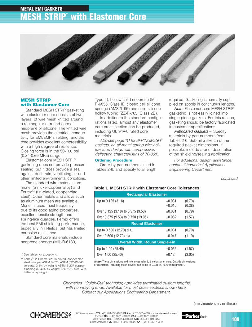
US Headquarters TEL +(1) 781-935-4850 FAX +(1) 781-933-4318 • www.chomerics.comEurope TEL +(44) 1628 404000 FAX +(44) 1628 404090
Asia Pacific TEL +(852) 2 428 8008 FAX +(852) 2 423 8253South America TEL +(55) 11 3917 1099 FAX +(55) 11 3917 0817
109
MESH STRIPwith Elastomer Core
Standard MESH STRIP gasketingwith elastomer core consists of twolayers* of wire mesh knitted arounda rectangular or round core ofneoprene or silicone. The knitted wiremesh provides the electrical conduc-tivity for EMI/EMP shielding, and thecore provides excellent compressibilitywith a high degree of resilience.Closing force is in the 50-100 psi(0.34-0.69 MPa) range.
Elastomer core MESH STRIPgasketing does not provide pressuresealing, but it does provide a sealagainst dust, rain, ventilating air andother limited environmental conditions.
The standard wire materials aremonel (a nickel-copper alloy) andFerrex** (tin-plated, copper-cladsteel). Other metals and alloys suchas aluminum mesh are available.Monel is used most frequentlydue to its good aging properties,excellent tensile strength andspring-like qualities. Ferrex offersthe best EMI shielding performance,especially in H-fields, but has limitedcorrosion resistance.
Standard core materials includeneoprene sponge (MIL-R-6130,
Type II), hollow solid neoprene (MIL-R-6855, Class II), closed cell siliconesponge (AMS-3195) and solid siliconehollow tubing (ZZ-R-765, Class 2B).
In addition to the standard configu-rations listed, almost any elastomercore cross section can be produced,including UL 94V-0 rated corematerials.
Also see page 111 for SPRINGMESH®
gaskets, an all-metal spring wire hol-low tube design with compression-deflection characteristics of 70-80%.
Ordering ProcedureOrder by part numbers listed in
Tables 2-6, and specify total length
Rectangular Elastomer
Up to 0.125 (3.18) +0.031 (0.79) –0.015 (0.38)
Over 0.125 (3.18) to 0.375 (9.53) ±0.031 (0.79)
Over 0.375 (9.53) to 0.750 (19.05) ±0.062 (1.57)
Round Elastomer
Up to 0.500 (12.70) dia. ±0.031 (0.79)
Over 0.500 (12.70) dia. ±0.047 (1.19)
Overall Width, Round Single-Fin
Up to 1.00 (25.40) ±0.062 (1.57)
Over 1.00 (25.40) ±0.12 (3.05)
Table 1 MESH STRIP with Elastomer Core Tolerances
(mm dimensions in parentheses)
required. Gasketing is normally sup-plied on spools in continuous lengths.
Note: Elastomer core MESH STRIPgasketing is not easily joined intosingle-piece gaskets. For this reason,gasketing should be factory fabricatedto customer specifications.
Fabricated Gaskets – Specifymaterials by part numbers fromTables 2-6. Submit a sketch of therequired gasket dimensions. Ifpossible, include a brief descriptionof the shielding/sealing application.
For additional design assistance,contact Chomerics’ ApplicationsEngineering Department.
* See tables for exceptions.
** Ferrex® is Chomerics’ tin-plated, copper-cladsteel wire per ASTM B-520. ASTM (QQ-W-343)tin-plate, 2-3% by weight; ASTM B-227 copper-cladding 30-40% by weight; SAE 1010 steel wire,balance by weight.
Note: These dimensions and tolerances refer to the elastomer core. Outside dimensionsor diameters, including mesh covers, can be up to 0.031 in. (0.79 mm) greater .
Chomerics’ “Quick-Cut” technology provides terminated custom lengthswith non-fraying ends. Available for most cross sections shown here.
Contact our Applications Engineering Department.
continued
METAL EMI GASKETS
MESH STRIP™ with Elastomer Core
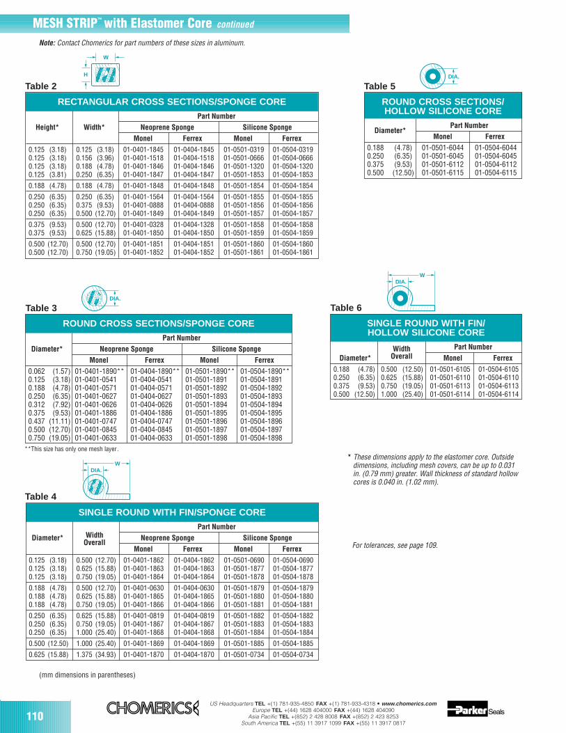
110US Headquarters TEL +(1) 781-935-4850 FAX +(1) 781-933-4318 • www.chomerics.com
Europe TEL +(44) 1628 404000 FAX +(44) 1628 404090Asia Pacific TEL +(852) 2 428 8008 FAX +(852) 2 423 8253
South America TEL +(55) 11 3917 1099 FAX +(55) 11 3917 0817
Table 2
Table 3
Table 5
**This size has only one mesh layer.
(mm dimensions in parentheses)
* These dimensions apply to the elastomer core. Outsidedimensions, including mesh covers, can be up to 0.031in. (0.79 mm) greater. Wall thickness of standard hollowcores is 0.040 in. (1.02 mm).
yyy
zzz||
W
H
yyyyyyyy
QQQQQ
¢¢¢¢¢
QQQQQ
¢¢¢¢¢
QQQQQ
¢¢¢¢¢
yyyy
zz|
DIA.
yyyy
zz|
DIA.
yyyy
QQQQQQ
¢¢¢¢¢¢
QQQQQ
¢¢¢¢¢
For tolerances, see page 109.
Note: Contact Chomerics for part numbers of these sizes in aluminum.
RECTANGULAR CROSS SECTIONS/SPONGE CORE
Part Number
Height* Width* Neoprene Sponge Silicone Sponge
Monel Ferrex Monel Ferrex
0.125 (3.18) 0.125 (3.18) 01-0401-1845 01-0404-1845 01-0501-0319 01-0504-03190.125 (3.18) 0.156 (3.96) 01-0401-1518 01-0404-1518 01-0501-0666 01-0504-06660.125 (3.18) 0.188 (4.78) 01-0401-1846 01-0404-1846 01-0501-1320 01-0504-13200.125 (3.81) 0.250 (6.35) 01-0401-1847 01-0404-1847 01-0501-1853 01-0504-1853
0.188 (4.78) 0.188 (4.78) 01-0401-1848 01-0404-1848 01-0501-1854 01-0504-1854
0.250 (6.35) 0.250 (6.35) 01-0401-1564 01-0404-1564 01-0501-1855 01-0504-18550.250 (6.35) 0.375 (9.53) 01-0401-0888 01-0404-0888 01-0501-1856 01-0504-18560.250 (6.35) 0.500 (12.70) 01-0401-1849 01-0404-1849 01-0501-1857 01-0504-1857
0.375 (9.53) 0.500 (12.70) 01-0401-0328 01-0404-1328 01-0501-1858 01-0504-18580.375 (9.53) 0.625 (15.88) 01-0401-1850 01-0404-1850 01-0501-1859 01-0504-1859
0.500 (12.70) 0.500 (12.70) 01-0401-1851 01-0404-1851 01-0501-1860 01-0504-18600.500 (12.70) 0.750 (19.05) 01-0401-1852 01-0404-1852 01-0501-1861 01-0504-1861
Table 4
yy
zzz
|||
WDIA.
yyyyyyyyy
QQQQQQ
¢¢¢¢¢¢
QQQQQQ
¢¢¢¢¢¢
SINGLE ROUND WITH FIN/SPONGE CORE
WidthPart Number
Diameter*Overall
Neoprene Sponge Silicone Sponge
Monel Ferrex Monel Ferrex
0.125 (3.18) 0.500 (12.70) 01-0401-1862 01-0404-1862 01-0501-0690 01-0504-06900.125 (3.18) 0.625 (15.88) 01-0401-1863 01-0404-1863 01-0501-1877 01-0504-18770.125 (3.18) 0.750 (19.05) 01-0401-1864 01-0404-1864 01-0501-1878 01-0504-1878
0.188 (4.78) 0.500 (12.70) 01-0401-0630 01-0404-0630 01-0501-1879 01-0504-18790.188 (4.78) 0.625 (15.88) 01-0401-1865 01-0404-1865 01-0501-1880 01-0504-18800.188 (4.78) 0.750 (19.05) 01-0401-1866 01-0404-1866 01-0501-1881 01-0504-1881
0.250 (6.35) 0.625 (15.88) 01-0401-0819 01-0404-0819 01-0501-1882 01-0504-18820.250 (6.35) 0.750 (19.05) 01-0401-1867 01-0404-1867 01-0501-1883 01-0504-18830.250 (6.35) 1.000 (25.40) 01-0401-1868 01-0404-1868 01-0501-1884 01-0504-1884
0.500 (12.50) 1.000 (25.40) 01-0401-1869 01-0404-1869 01-0501-1885 01-0504-1885
0.625 (15.88) 1.375 (34.93) 01-0401-1870 01-0404-1870 01-0501-0734 01-0504-0734
Table 6
yy
zzz
|||
WDIA.
SINGLE ROUND WITH FIN/HOLLOW SILICONE CORE
Width Part Number
Diameter* Overall Monel Ferrex
0.188 (4.78) 0.500 (12.50) 01-0501-6105 01-0504-61050.250 (6.35) 0.625 (15.88) 01-0501-6110 01-0504-61100.375 (9.53) 0.750 (19.05) 01-0501-6113 01-0504-61130.500 (12.50) 1.000 (25.40) 01-0501-6114 01-0504-6114
ROUND CROSS SECTIONS/SPONGE CORE
Part Number
Diameter* Neoprene Sponge Silicone Sponge
Monel Ferrex Monel Ferrex
0.062 (1.57) 01-0401-1890** 01-0404-1890** 01-0501-1890** 01-0504-1890**0.125 (3.18) 01-0401-0541 01-0404-0541 01-0501-1891 01-0504-18910.188 (4.78) 01-0401-0571 01-0404-0571 01-0501-1892 01-0504-18920.250 (6.35) 01-0401-0627 01-0404-0627 01-0501-1893 01-0504-18930.312 (7.92) 01-0401-0626 01-0404-0626 01-0501-1894 01-0504-18940.375 (9.53) 01-0401-1886 01-0404-1886 01-0501-1895 01-0504-18950.437 (11.11) 01-0401-0747 01-0404-0747 01-0501-1896 01-0504-18960.500 (12.70) 01-0401-0845 01-0404-0845 01-0501-1897 01-0504-18970.750 (19.05) 01-0401-0633 01-0404-0633 01-0501-1898 01-0504-1898
ROUND CROSS SECTIONS/HOLLOW SILICONE CORE
Diameter*Part Number
Monel Ferrex
0.188 (4.78) 01-0501-6044 01-0504-60440.250 (6.35) 01-0501-6045 01-0504-60450.375 (9.53) 01-0501-6112 01-0504-61120.500 (12.50) 01-0501-6115 01-0504-6115
MESH STRIP™ with Elastomer Core continued
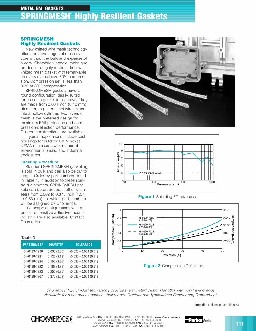
US Headquarters TEL +(1) 781-935-4850 FAX +(1) 781-933-4318 • www.chomerics.comEurope TEL +(44) 1628 404000 FAX +(44) 1628 404090
Asia Pacific TEL +(852) 2 428 8008 FAX +(852) 2 423 8253South America TEL +(55) 11 3917 1099 FAX +(55) 11 3917 0817 111
METAL EMI GASKETS
SPRINGMESH® Highly Resilient Gaskets
SPRINGMESHHighly Resilient Gaskets
New knitted wire mesh technologyoffers the advantages of mesh overcore without the bulk and expense ofa core. Chomerics’ special techniqueproduces a highly resilient, hollowknitted mesh gasket with remarkablerecovery even above 70% compres-sion. Compression set is less than30% at 80% compression.
SPRINGMESH gaskets have around configuration ideally suitedfor use as a gasket-in-a-groove. Theyare made from 0.004 inch (0.10 mm)diameter tin-plated steel wire knittedinto a hollow cylinder. Two layers ofmesh is the preferred design formaximum EMI protection and com-pression-deflection performance.Custom constructions are available.
Typical applications include casthousings for outdoor CATV boxes,NEMA enclosures with outboardenvironmental seals, and industrialenclosures.
Ordering ProcedureStandard SPRINGMESH gasketing
is sold in bulk and can also be cut tolength. Order by part numbers listedin Table 1. In addition to these stan-dard diameters, SPRINGMESH gas-kets can be produced in other diam-eters from 0.062 to 0.375 inch (1.57to 9.53 mm), for which part numberswill be assigned by Chomerics.
“D” shape configurations with apressure-sensitive adhesive mount-ing strip are also available. ContactChomerics.
PART NUMBER DIAMETER TOLERANCE
01-0199-7298 0.093 (2.36) +0.020,–0.000 (0.51)01-0199-7321 0.125 (3.18) +0.020,–0.000 (0.51)01-0199-7324 0.156 (3.96) +0.020,–0.000 (0.51)01-0199-7322 0.188 (4.78) +0.020,–0.000 (0.51)01-0199-7323 0.250 (6.35) +0.032,–0.000 (0.81)01-0199-7367 0.375 (9.53) +0.032,–0.000 (0.81)
1
0.8
0.6
0.4
0.2
0
0.175
0.140
0.105
0.070
0.035
0 10 20 30 40 50Deflection (%)
Co
mp
ress
ion
(lb
/inch
) Co
mp
ression
(N/m
m)
01-0199-73220.188 (4.78)
01-0199-73230.250 (6.35)
01-0199-73210.125 (3.18)
Table 1
(mm dimensions in parentheses)
Figure 2 Compression-Deflection
Chomerics’ “Quick-Cut” technology provides terminated custom lengths with non-fraying ends.Available for most cross sections shown here. Contact our Applications Engineering Department.
0
20
40
60
80
100
Att
enu
atio
n (
dB
)
10 100 1000 10000Frequency (MHz)
P/N 01-0199-7323
Figure 1 Shielding Effectiveness
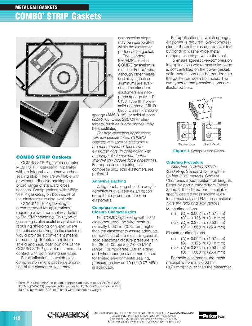
112US Headquarters TEL +(1) 781-935-4850 FAX +(1) 781-933-4318 • www.chomerics.com
Europe TEL +(44) 1628 404000 FAX +(44) 1628 404090Asia Pacific TEL +(852) 2 428 8008 FAX +(852) 2 423 8253
South America TEL +(55) 11 3917 1099 FAX +(55) 11 3917 0817
compression stopsmay be incorporatedwithin the elastomerportion of the gasket.
The standardEMI/EMP shield inCOMBO gasketing ismonel or Ferrex* wire,although other metalsand alloys (such asaluminum) are avail-able. The standardelastomers are neo-prene sponge (MIL-R-6130, Type II), hollowsolid neoprene (MIL-R-6855, Class II), silicone
sponge (AMS-3195), or solid silicone(ZZ-R-765, Class 2B). Other elas-tomers, such as fluorosilicones, maybe substituted.
For high deflection applicationswith low closure force, COMBO gaskets with sponge elastomers are recommended. Mesh over elastomer core, in conjunction with a sponge elastomer, can furtherimprove low closure force capabilities.For applications requiring lesscompressibility, solid elastomers arepreferred.
Adhesive BackingA high tack, long shelf-life acrylic
adhesive is available as an optionon both neoprene and siliconeelastomers.
Compression andClosure Characteristics
For COMBO gasketing with solidelastomer core, the wire mesh isnormally 0.031 in. (0.79 mm) higherthan the elastomer to assure adequatecompression of the mesh. In general,solid elastomer closure pressure is inthe 25 to 100 psi (0.17-0.69 MPa)range. For moderate EMI shielding,and when sponge elastomer is usedfor limited environmental sealing,pressure as low as 10 psi (0.07 MPa)is adequate.
COMBO STRIP GasketsCOMBO STRIP gaskets combine
MESH STRIP gasketing in parallelwith an integral elastomer weather-sealing strip. They are available withor without adhesive backing in abroad range of standard crosssections. Configurations with MESHSTRIP gasketing on both sides ofthe elastomer are also available.
COMBO STRIP gasketing isrecommended for applicationsrequiring a weather seal in additionto EMI/EMP shielding. This type ofgasketing is also useful in applicationsrequiring shielding only and wherethe adhesive backing on the elastomerwould provide a convenient meansof mounting. To obtain a reliableshield and seal, both portions of theCOMBO STRIP gasket must come incontact with both mating surfaces.
For applications in which over-compression might cause deteriora-tion of the elastomer seal, metal
For applications in which spongeelastomer is required, over-compres-sion at the bolt holes can be avoidedby bonding washer-type metalcompression stops within the seal.
To ensure against over-compressionin applications where excessive forceis concentrated on the cover gasket,solid metal stops can be bonded intothe gasket between bolt holes. Thetwo types of compression stops areillustrated here.
Ordering ProcedureStandard COMBO STRIP
Gasketing: Standard roll length is 25 feet (7.62 meters). ContactChomerics about custom roll lengths.Order by part numbers from Tables2 and 3. If no listed part is suitable,specify desired cross section, elas-tomer material, and EMI mesh material.Note the following size ranges:Mesh dimensions
min. (C) = 0.062 in. (1.57 mm)(D) = 0.125 in. (3.18 mm)
max. (C) = 0.375 in. (9.53 mm)(D) = 1.000 in. (25.4 mm)
Elastomer dimensions
min. (A) = 0.062 in. (1.57 mm)(B) = 0.125 in. (3.18 mm)
max. (A) = 0.375 in. (9.53 mm)(B) = 1.000 in. (25.4 mm)
For solid elastomers, the meshmaterial is normally 0.031 in.(0.79 mm) thicker than the elastomer.
* Ferrex® is Chomerics’ tin-plated, copper clad steel wire per ASTM B-520.ASTM (QQ-W-343) tin-plate, 2-3% by weight; ASTM B-227 copper-cladding30-40% by weight; SAE 1010 steel wire, balance by weight.
Washer Type Solid Metal
Figure 1 Compression Stops
METAL EMI GASKETS
COMBO® STRIP Gaskets
Bolt Holes
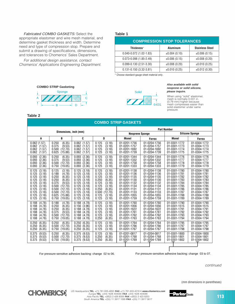
US Headquarters TEL +(1) 781-935-4850 FAX +(1) 781-933-4318 • www.chomerics.comEurope TEL +(44) 1628 404000 FAX +(44) 1628 404090
Asia Pacific TEL +(852) 2 428 8008 FAX +(852) 2 423 8253South America TEL +(55) 11 3917 1099 FAX +(55) 11 3917 0817
113
Silicone Sponge
A B C D Monel Monel
0.062 (1.57) 0.250 (6.35) 0.062 (1.57) 0.125 (3.18) 01-0201-1756 01-0204-1756 01-0301-1772 01-0304-17720.062 (1.57) 0.375 (9.53) 0.062 (1.57) 0.125 (3.18) 01-0201-1757 01-0204-1757 01-0301-1773 01-0304-17730.062 (1.57) 0.500 (12.70) 0.062 (1.57) 0.125 (3.18) 01-0201-1692 01-0204-1692 01-0301-1774 01-0304-17740.062 (1.57) 0.625 (15.88) 0.062 (1.57) 0.125 (3.18) 01-0201-1739 01-0204-1739 01-0301-1775 01-0304-17750.093 (2.36) 0.250 (6.35) 0.093 (2.36) 0.125 (3.18) 01-0201-1344 01-0204-1344 01-0301-1776 01-0304-17760.093 (2.36) 0.375 (9.53) 0.093 (2.36) 0.125 (3.18) 01-0201-1332 01-0204-1332 01-0301-1777 01-0304-17770.093 (2.36) 0.500 (12.70) 0.093 (2.36) 0.125 (3.18) 01-0201-1758 01-0204-1758 01-0301-1778 01-0304-17780.093 (2.36) 0.750 (19.05) 0.093 (2.36) 0.125 (3.18) 01-0201-1333 01-0204-1333 01-0301-1779 01-0304-17790.125 (3.18) 0.125 (3.18) 0.125 (3.18) 0.125 (3.18) 01-0201-1138 01-0204-1138 01-0301-1780 01-0304-17800.125 (3.18) 0.188 (4.78) 0.125 (3.18) 0.125 (3.18) 01-0201-1136 01-0204-1136 01-0301-1781 01-0304-17810.125 (3.18) 0.250 (6.35) 0.125 (3.18) 0.125 (3.18) 01-0201-1135 01-0204-1135 01-0301-1782 01-0304-17820.125 (3.18) 0.250 (6.35) 0.125 (3.18) 0.250 (6.35) 01-0201-1130 01-0204-1130 01-0301-1783 01-0304-17830.125 (3.18) 0.375 (9.53) 0.125 (3.18) 0.125 (3.18) 01-0201-1132 01-0204-1132 01-0301-1784 01-0304-17840.125 (3.18) 0.500 (12.70) 0.125 (3.18) 0.125 (3.18) 01-0201-1134 01-0204-1134 01-0301-1785 01-0304-17850.125 (3.18) 0.500 (12.70) 0.125 (3.18) 0.250 (6.35) 01-0201-1131 01-0204-1131 01-0301-1786 01-0304-17860.125 (3.18) 0.500 (12.70) 0.125 (3.18) 0.500 (12.70) 01-0201-1133 01-0204-1133 01-0301-1787 01-0304-17870.125 (3.18) 0.625 (15.88) 0.125 (3.18) 0.125 (3.18) 01-0201-1055 01-0204-1055 01-0301-1788 01-0304-17880.125 (3.18) 0.750 (19.05) 0.125 (3.18) 0.125 (3.18) 01-0201-1759 01-0204-1759 01-0301-1789 01-0304-17890.188 (4.78) 0.188 (4.78) 0.188 (4.78) 0.125 (3.18) 01-0201-1760 01-0204-1760 01-0301-1790 01-0304-17900.188 (4.78) 0.250 (6.35) 0.156 (3.96) 0.125 (3.18) 01-0201-1056 01-0204-1056 01-0301-1515 01-0304-15150.188 (4.78) 0.250 (6.35) 0.188 (4.78) 0.125 (3.18) 01-0201-1622 01-0204-1622 01-0301-1791 01-0304-17910.188 (4.78) 0.375 (9.53) 0.188 (4.78) 0.125 (3.18) 01-0201-1761 01-0204-1761 01-0301-1792 01-0304-17920.188 (4.78) 0.500 (12.70) 0.188 (4.78) 0.125 (3.18) 01-0201-1762 01-0204-1762 01-0301-1793 01-0304-17930.188 (4.78) 0.750 (19.05) 0.188 (4.78) 0.250 (6.35) 01-0201-1763 01-0204-1763 01-0301-1794 01-0304-17940.250 (6.35) 0.250 (6.35) 0.250 (6.35) 0.125 (3.18) 01-0201-1764 01-0204-1764 01-0301-1795 01-0304-17950.250 (6.35) 0.500 (12.70) 0.250 (6.35) 0.125 (3.18) 01-0201-1766 01-0204-1766 01-0301-1797 01-0304-17970.250 (6.35) 0.750 (19.05) 0.250 (6.35) 0.125 (3.18) 01-0201-1767 01-0204-1767 01-0301-1798 01-0304-17980.375 (9.53) 0.250 (6.35) 0.375 (9.53) 0.125 (3.18) 01-0201-0817 01-0204-0817 01-0301-1800 01-0304-18000.375 (9.53) 0.500 (12.70) 0.375 (9.53) 0.250 (6.35) 01-0201-1768 01-0204-1768 01-0301-1801 01-0304-18010.375 (9.53) 0.750 (19.05) 0.375 (9.53) 0.250 (6.35) 01-0201-1769 01-0204-1769 01-0301-1802 01-0304-1802
COMBO STRIP GASKETS
Neoprene SpongePart Number
FerrexFerrex
Dimensions, inch (mm)
For pressure-sensitive adhesive backing: change 02 to 06. For pressure-sensitive adhesive backing: change 03 to 07.
(mm dimensions in parentheses)
Fabricated COMBO GASKETS: Select theappropriate elastomer and wire mesh material, anddetermine gasket thickness and width. Determineneed and type of compression stop. Prepare andsubmit a drawing of specifications, dimensions,and tolerances to Chomerics’ Sales Department.
For additional design assistance, contactChomerics’ Applications Engineering Department.
CA
B D
Sponge
COMPRESSION STOP TOLERANCES
Thickness* Aluminum Stainless Steel
0.040-0.072 (1.02-1.83) ±0.004 (0.10) ±0.006 (0.15)
0.073-0.098 (1.85-2.49) ±0.006 (0.15) ±0.008 (0.20)
0.099-0.130 (2.51-3.30) ±0.008 (0.20) ±0.010 (0.25)
0.131-0.150 (3.32-3.81) ±0.010 (0.25) ±0.012 (0.30)
Table 1
continued
* Choose standard-gauge sheet material only.
Also available with solidneoprene or solid silicone,please inquire.
Table 2
COMBO STRIP Gasketing
When using “solid” elastomer,mesh is normally 0.031 in.(0.79 mm) higher becausemesh compresses easier thansolid elastomer under samepressure.
Solid
0.031
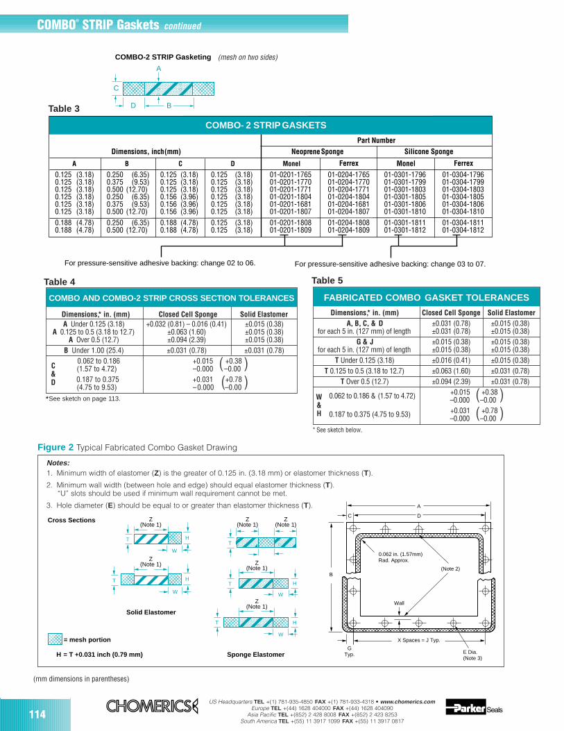
114US Headquarters TEL +(1) 781-935-4850 FAX +(1) 781-933-4318 • www.chomerics.com
Europe TEL +(44) 1628 404000 FAX +(44) 1628 404090Asia Pacific TEL +(852) 2 428 8008 FAX +(852) 2 423 8253
South America TEL +(55) 11 3917 1099 FAX +(55) 11 3917 0817
Figure 2 Typical Fabricated Combo Gasket Drawing
Dimensions,* in. (mm) Closed Cell Sponge Solid ElastomerA, B, C, & D ±0.031 (0.78) ±0.015 (0.38)
for each 5 in. (127 mm) of length ±0.031 (0.78) ±0.015 (0.38)G & J ±0.015 (0.38) ±0.015 (0.38)
for each 5 in. (127 mm) of length ±0.015 (0.38) ±0.015 (0.38)T Under 0.125 (3.18) ±0.016 (0.41) ±0.015 (0.38)
T 0.125 to 0.5 (3.18 to 12.7) ±0.063 (1.60) ±0.031 (0.78)T Over 0.5 (12.7) ±0.094 (2.39) ±0.031 (0.78)
0.062 to 0.186 & (1.57 to 4.72) +0.015 ( +0.38 )–0.000 –0.00
0.187 to 0.375 (4.75 to 9.53) +0.031 ( +0.78 )–0.000 –0.00
Part Number
Dimensions, inch (mm) Neoprene Sponge Silicone Sponge
A B C D Monel FerrexFerrex Monel
0.125 (3.18) 0.250 (6.35) 0.125 (3.18) 0.125 (3.18) 01-0201-1765 01-0204-1765 01-0301-1796 01-0304-17960.125 (3.18) 0.375 (9.53) 0.125 (3.18) 0.125 (3.18) 01-0201-1770 01-0204-1770 01-0301-1799 01-0304-17990.125 (3.18) 0.500 (12.70) 0.125 (3.18) 0.125 (3.18) 01-0201-1771 01-0204-1771 01-0301-1803 01-0304-18030.125 (3.18) 0.250 (6.35) 0.156 (3.96) 0.125 (3.18) 01-0201-1804 01-0204-1804 01-0301-1805 01-0304-18050.125 (3.18) 0.375 (9.53) 0.156 (3.96) 0.125 (3.18) 01-0201-1681 01-0204-1681 01-0301-1806 01-0304-18060.125 (3.18) 0.500 (12.70) 0.156 (3.96) 0.125 (3.18) 01-0201-1807 01-0204-1807 01-0301-1810 01-0304-18100.188 (4.78) 0.250 (6.35) 0.188 (4.78) 0.125 (3.18) 01-0201-1808 01-0204-1808 01-0301-1811 01-0304-18110.188 (4.78) 0.500 (12.70) 0.188 (4.78) 0.125 (3.18) 01-0201-1809 01-0204-1809 01-0301-1812 01-0304-1812
COMBO- 2 STRIP GASKETS
For pressure-sensitive adhesive backing: change 02 to 06. For pressure-sensitive adhesive backing: change 03 to 07.
C
D
A
B
COMBO-2 STRIP Gasketing
(mm dimensions in parentheses)
Dimensions,* in. (mm) Closed Cell Sponge Solid ElastomerA Under 0.125 (3.18) +0.032 (0.81) – 0.016 (0.41) ±0.015 (0.38)
A 0.125 to 0.5 (3.18 to 12.7) ±0.063 (1.60) ±0.015 (0.38)A Over 0.5 (12.7) ±0.094 (2.39) ±0.015 (0.38)
B Under 1.00 (25.4) ±0.031 (0.78) ±0.031 (0.78)0.062 to 0.186 +0.015 ( +0.38 )(1.57 to 4.72) –0.000 –0.000.187 to 0.375 +0.031 (+0.78 )(4.75 to 9.53) –0.000 –0.00
* See sketch on page 113.
FABRICATED COMBO GASKET TOLERANCES
* See sketch below.
COMBO AND COMBO-2 STRIP CROSS SECTION TOLERANCES
W&H
C&D
H
H
H
H
T
T
T
T
T
Z(Note 1)
Z(Note 1)
Z(Note 1)
Z(Note 1)
Z(Note 1)
Z(Note 1)
WW
W
W
D
A
0.062 in. (1.57mm)Rad. Approx.
Wall
(Note 2)B
X Spaces = J Typ.
GTyp.
C
E Dia.(Note 3)
Cross Sections
= mesh portion
= T +0.031 inch (0.79 mm)H
Solid Elastomer
Sponge Elastomer
Notes:1. Minimum width of elastomer (Z) is the greater of 0.125 in. (3.18 mm) or elastomer thickness (T).
2. Minimum wall width (between hole and edge) should equal elastomer thickness (T).“U” slots should be used if minimum wall requirement cannot be met.
3. Hole diameter (E) should be equal to or greater than elastomer thickness (T).
Table 4 Table 5
(mesh on two sides)
COMBO® STRIP Gaskets continued
Table 3
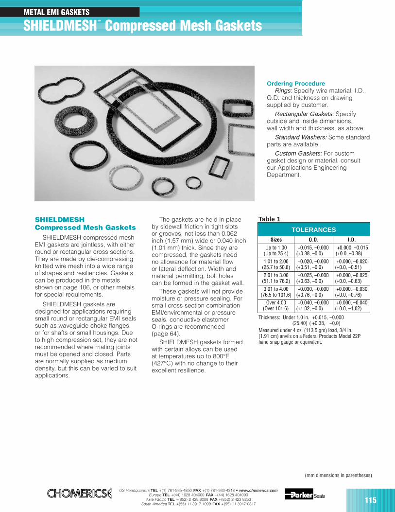
US Headquarters TEL +(1) 781-935-4850 FAX +(1) 781-933-4318 • www.chomerics.comEurope TEL +(44) 1628 404000 FAX +(44) 1628 404090
Asia Pacific TEL +(852) 2 428 8008 FAX +(852) 2 423 8253South America TEL +(55) 11 3917 1099 FAX +(55) 11 3917 0817 115
SHIELDMESHCompressed Mesh Gaskets
SHIELDMESH compressed meshEMI gaskets are jointless, with eitherround or rectangular cross sections.They are made by die-compressingknitted wire mesh into a wide range of shapes and resiliencies. Gasketscan be produced in the metalsshown on page 106, or other metalsfor special requirements.
SHIELDMESH gaskets are designed for applications requiringsmall round or rectangular EMI sealssuch as waveguide choke flanges,or for shafts or small housings. Dueto high compression set, they are notrecommended where mating jointsmust be opened and closed. Partsare normally supplied as mediumdensity, but this can be varied to suitapplications.
The gaskets are held in placeby sidewall friction in tight slotsor grooves, not less than 0.062inch (1.57 mm) wide or 0.040 inch(1.01 mm) thick. Since they arecompressed, the gaskets needno allowance for material flowor lateral deflection. Width andmaterial permitting, bolt holescan be formed in the gasket wall.
These gaskets will not provide moisture or pressure sealing. For small cross section combinationEMI/environmental or pressureseals, conductive elastomerO-rings are recommended (page 64).
SHIELDMESH gaskets formed with certain alloys can be usedat temperatures up to 800°F(427°C) with no change to theirexcellent resilience.
Thickness: Under 1.0 in. +0.015, –0.000(25.40) ( +0.38, –0.0)
Measured under 4 oz. (113.5 gm) load, 3/4 in.(1.91 cm) anvils on a Federal Products Model 22Phand snap gauge or equivalent.
Ordering ProcedureRings: Specify wire material, I.D.,
O.D. and thickness on drawingsupplied by customer.
Rectangular Gaskets: Specify outside and inside dimensions,wall width and thickness, as above.
Standard Washers: Some standardparts are available.
Custom Gaskets: For custom gasket design or material, consultour Applications EngineeringDepartment.
TOLERANCESSizes O.D. I.D.
Up to 1.00(Up to 25.4)
(+0.015, –0.000(+0.38, –0.0)
(+0.000, –0.015(+0.0, –0.38)
1.01 to 2.00(25.7 to 50.8)
(+0.020, –0.000(+0.51, –0.0)
(+0.000, –0.020(+0.0, –0.51)
2.01 to 3.00(51.1 to 76.2)
(+0.025, –0.000(+0.63, –0.0)
+0.000, –0.025(+0.0, –0.63)
3.01 to 4.00(76.5 to 101.6)
(+0.030, –0.000(+0.76, –0.0)
+0.000, –0.030(+0.0, –0.76)
Over 4.00(Over 101.6)
(+0.040, –0.000(+1.02, –0.0)
+0.000, –0.040(+0.0, –1.02)
Table 1
METAL EMI GASKETS
SHIELDMESH™ Compressed Mesh Gaskets
(mm dimensions in parentheses)
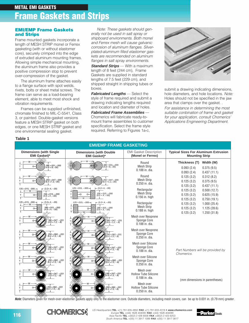
116US Headquarters TEL +(1) 781-935-4850 FAX +(1) 781-933-4318 • www.chomerics.com
Europe TEL +(44) 1628 404000 FAX +(44) 1628 404090Asia Pacific TEL +(852) 2 428 8008 FAX +(852) 2 423 8253
South America TEL +(55) 11 3917 1099 FAX +(55) 11 3917 0817
EMI/EMP Frame Gasketsand StripsFrame mounted gaskets incorporate alength of MESH STRIP monel or Ferrexgasketing (with or without elastomercore), securely crimped into the edgeof extruded aluminum mounting frames.Allowing simple mechanical mounting,the aluminum frame also provides apositive compression stop to preventover-compression of the gasket.
The aluminum frame attaches easilyto a flange surface with spot welds, rivets, bolts or sheet metal screws. Theframe can serve as a load-bearing element, able to meet most shock andvibration requirements.
Frames can be supplied unfinished,chromate finished to MIL-C-5541, Class3, or painted. Double-gasket versionsfeature a MESH STRIP gasket on bothedges, or one MESH STRIP gasket andone environmental sealing gasket.
Table 1
Note: Diameters given for mesh-over-elastomer gaskets apply only to the elastomer core. Outside diameters, including mesh covers, can be up to 0.031 in. (0.79 mm) greater .
METAL EMI GASKETS
Frame Gaskets and Strips
Round Mesh Strip
0.188 in. dia.
Round Mesh Strip
0.250 in. dia.
RectangularMesh Strip
0.156 in. high
RectangularMesh Strip
0.188 in. high
Mesh over NeopreneSponge Core0.250 in. dia.
Mesh over SiliconeSponge Core0.188 in. dia.
Mesh over SiliconeSponge Core0.250 in. dia.
Mesh over Hollow Tube Silicone
0.250 in. dia.
Mesh over NeopreneSponge Core0.188 in. dia.
Mesh over Hollow Tube Silicone
0.188 in. dia.
.250 +.047,Ð.000(6.4 +1.2,Ð.00)T
W
T
W
.156 +.015, Ð.000(4.0 +.4 ,Ð.00)
.125 +.015, -.000 (3.2+.4, Ð.00)
T
W.125 +.015, -.000 (3.2+.4, Ð.00)
.188 +.015, Ð.000(4.8 +.4, Ð.00)
T
W
.188 +.047, Ð.031(4.8 +.1.2, Ð.8)
T
W
.250 +.062, Ð.031(6.4 +1.5, Ð.8)
T
W
.188 +.047, Ð.031(4.8 +1.2, Ð.8)
T
W
.250 +.062, Ð.031(6.4 +1.5, Ð.8)
.188 +.047, Ð.031(4.8 +1.2, Ð.8)
T
W
T
W
.250+.062,Ð.031(6.4 +1.5, Ð.8)
EMI/EMP FRAME GASKETING
T
W
.125 +.015, –.000 (3.2+.4, –.00)
.188 +.015, –.000(4.8 +.4, –.00)
T
W
.250 +.047,–.000(6.4 +1.2,–.00)
T
W .188 +.047, –.031
(4.8 +.1.2, –.8)
T
W
.188 +.047,Ð.031(4.8 +1.2, Ð.8)
T
W
.156 +.015, –.000(4.0 +.4 ,–.00)
.125 +.015, –.000 (3.2+.4, –.00)
T
W
.188 +.047,Ð.031(4.8 +1.2, Ð.8)
T
W
.250 +.062, Ð.031(6.4 +1.5, Ð.8)
T
W .250 +.062, –.031
(6.4 +1.5, –.8)
.188 +.031,–.000(4.8 +.8,–.00)T
W
T
W
.250+.062,Ð.031(6.4 +1.5, Ð.8)
.188 +.031,Ð.000(4.8 +.8,Ð.00)T
W
Dimensions (with SingleEMI Gasket)*
Dimensions (with DoubleEMI Gasket)*
Typical Sizes For Aluminum ExtrusionMounting Strip
EMI Gasket Description(Monel or Ferrex)
Thickness (T) Width (W)
0.093 (2.4) 0.375 (9.5)0.093 (2.4) 0.437 (11.1)0.125 (3.2) 0.312 (8.2)0.125 (3.2) 0.375 (9.5)0.125 (3.2) 0.437 (11.1)0.125 (3.2) 0.500 (12.7)0.125 (3.2) 0.625 (15.9)0.125 (3.2) 0.750 (19.1)0.125 (3.2) 1.000 (25.4)0.125 (3.2) 1.125 (28.6)0.125 (3.2) 1.250 (31.8)
Note: These gaskets should gen-erally not be used in salt spray orshipboard environments. Both moneland Ferrex mesh will cause galvaniccorrosion of aluminum flanges. Silver-plated-aluminum filled elastomer gas-kets are recommended on aluminumflanges in salt spray environments.Standard Strips — With a maximumlength of 8 feet (244 cm), FrameGaskets are supplied in standardlengths of 7.5 feet (229 cm), andshipped straight in shipping tubes orboxes.Fabricated Lengths — Select thestyle of frame required and submit adrawing indicating lengths requiredand location and diameter of holes.Fabricated Frame Assemblies —Chomerics will fabricate ready-to-mount frame assemblies to customerspecification. Select the frame stylerequired. Referring to Figures 1a-c,
submit a drawing indicating dimensions,hole diameters, and hole locations. Note:Holes should not be specified in the jawarea that clamps over the gasket. .For assistance in determining the mostsuitable conbination of frame and gasketfor your application, consult Chomerics’Applications Engineering Department.
Part Numbers will be provided byChomerics.
(mm dimensions in parentheses)
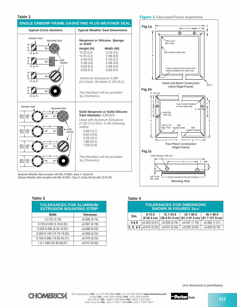
US Headquarters TEL +(1) 781-935-4850 FAX +(1) 781-933-4318 • www.chomerics.comEurope TEL +(44) 1628 404000 FAX +(44) 1628 404090
Asia Pacific TEL +(852) 2 428 8008 FAX +(852) 2 423 8253South America TEL +(55) 11 3917 1099 FAX +(55) 11 3917 0817
117
TOLERANCES FOR ALUMINUM EXTRUSION MOUNTING STRIP
Width Tolerances
<0.125 (3.18) ±0.006 (0.15)
0.125-0.249 (3.18-6.32) ±0.007 (0.18)
0.250-0.499 (6.35-12.67) ±0.008 (0.20)
0.500-0.749 (12.70-19.02) ±0.009 (0.23)
0.750-0.999 (19.05-25.37) ±0.010 (0.25)
1.0-1.499 (25.40-38.07) ±0.012 (0.30)
TOLERANCES FOR DIMENSONS SHOWN IN FIGURES 1a-c
Dim. 0-12.0(0-30.5 cm)
12.1-24.0(30.8-61.0 cm)
24.1-36.0(61.2-91.4 cm)
36.1-48.0(91.7-121.9 cm)
A & B ±0.020 (0.51) ±0.030 (0.76) ±0.047 (1.19) ±0.062 (1.57)C, D, & E ±0.010 (0.25) ±0.015 (0.38) ±0.025 (0.63) ±0.030 (0.76)
H
W
H
W
H
W
H
W
Mounting StripWeather Seal
EMIGasket
W .250 ±.031
(6.4 ±.8)
W .250 ±.031
(6.4 ±.8)
.250 ±.031(6.4 ±.8)
W
.250 ±.031(6.4 ±.8)
W
EMIGasket
Weather SealMounting Strip
Table 2
SINGLE EMI/EMP FRAME GASKETING PLUS WEATHER SEAL
Table 3 Table 4
Typical Cross Sections Typical Weather Seal Dimensions
Neoprene or Silicone, Sponge or SolidHeight (H) Width (W)*0.125 (3.2) 0.125 (3.2)*0.125 (3.2) 0.188 (4.8)
0.156 (4.0) 0.125 (3.2)0.188 (4.8) 0.188 (4.8)0.250 (6.4) 0.188 (4.8)0.250 (6.4) 0.250 (6.4)
*Aluminum Extrusions 0.093 (2.4 thick). All others 0.125 (3.2).
Part Numbers will be provided by Chomerics.
Neoprene Weather Seal complies with MIL-R-6855, Class II, Grade 40. Silicone Weather Seal complies with MIL-R-5847, Class II, Grade 40 and with ZZ-R-765.
Solid Neoprene or Solid SiliconeTube Diameter: 0.250 (6.4)Used with Aluminum Extrusions 0.125 (3.2) thick, in the following widths:
0.500 (12.7)0.625 (15.9)0.750 (19.1)1.000 (25.4)1.250 (31.8)
Part Numbers will be providedby Chomerics.
E
E
CC
D D
A A
B B
ECD
A
E
CDA
B
Four Corners Weldedon One Side Only
Hole Dia..005 (.13)
.062 (1.57)Max. Rad.
.062 (1.57)Max. Rad.
EMI Gasket Inside Only
Min R.
Frame Joined at One Corner andHeli-arc Welded One Side Only
Notch and Bend Construction(Semi-Rigid Frame)
Four-Piece Construction(Rigid Frame)
EMIGasket Inside EMI
Gasket Outside
.125 (3.18)Min. Wall
Ends Finished to Prevent Fraying
Mounting Strip
Hole Diameter .005 (.13)
Figure 1 Fabricated Frame Assemblies
Fig.1a
Fig.1b
Fig.1c
(mm dimensions in parentheses)
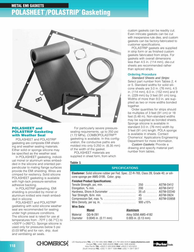
118US Headquarters TEL +(1) 781-935-4850 FAX +(1) 781-933-4318 • www.chomerics.com
Europe TEL +(44) 1628 404000 FAX +(44) 1628 404090Asia Pacific TEL +(852) 2 428 8008 FAX +(852) 2 423 8253
South America TEL +(55) 11 3917 1099 FAX +(55) 11 3917 0817
POLASHEET andPOLASTRIP Gasketingwith Weather Seal
POLASHEET and POLASTRIPgasketing are composite EMI shield-ing and weather sealing materials.Either solid or sponge silicone maybe specified as the weather seal.
In POLASHEET gasketing, individ-ual monel or aluminum wires embed-ded in the silicone and oriented per-pendicular to mating flange surfacesprovide the EMI shielding. Wires arecrimped for resiliency. Solid siliconePOLASHEET gasketing is availablewith high-tack pressure-sensitiveadhesive backing.
In POLASTRIP gasketing, EMIshielding is provided by monel oraluminum knitted wire mesh embed-ded in silicone.
POLASHEET and POLASTRIPgasketing with solid silicone weatherseal are recommended for sealingunder high pressure conditions.The silicone seal is rated for use attemperatures from –70°F (–56.7°C) to+500°F (+260°C). Sponge silicone isused only for pressures below 5 psi(0.03 MPa) and for rain, drip, dustand ventilating air seals.
For particularly severe pressure-sealing requirements, up to 250 psi(1.72 MPa), COMBOPOLASTRIP®
gasketing is available. In this config-uration, the conductive paths aremolded into only 0.250 in. (6.35 mm)of the width of the gasket.
POLASHEET materials aresupplied in sheet form, from which
custom gaskets can be readily cut.Even intricate gaskets can be cutwith inexpensive rule dies, and customgaskets can be factory-fabricated tocustomer specifications.
POLASTRIP gaskets are suppliedin strip form or as finished customgaskets fabricated from strips. Forgaskets with overall dimensionsless than 4.5 in. (114 mm), die-cutsheets are recommended ratherthan spliced strips.
Ordering ProcedureStandard Sheets and Strips:
Select part number from Tables 2, 4or 5. Standard widths for solid sili-cone sheets are 3.0 in. (76 mm), 4.5in. (114 mm), 6.0 in. (152 mm) and 9in. (229 mm) by 3 feet (91 cm) long.Widths of more than 9.0 in. are sup-plied as two or more widths bondedtogether.
Order quantities for strips shouldbe multiples of 3 feet (91 cm) or 18feet (5.48 m). Non-standard widthsmay be supplied as bonded sheets.Sponge silicone is available instandard 3.0 in. (76 mm) width by3 feet (91 cm) length. POLA spongeis available in sheets. ContactChomerics’ Applications EngineeringDepartment for more information.
Custom Gaskets: Provide adrawing and specify material partnumber from tables.
SPECIFICATIONS
Elastomer: Solid silicone rubber per Fed. Spec. ZZ-R-765, Class 2B, Grade 40; or sili-cone sponge per AMS-3195. Color, gray.Finished Product Specifications:Tensile Strength, psi, min. . . . . . . . . . . . . . . . . . . . . . 250 . . . . . . . . ASTM-D412Elongation, % min. . . . . . . . . . . . . . . . . . . . . . . . . . . 200 . . . . . . . . ASTM-D412Hardness, Shore A Durometer . . . . . . . . . . . . . . . . . . 35 ±5 . . . . . . . ASTM-D2240Tear Strength, lb/in. min. . . . . . . . . . . . . . . . . . . . . . . 45 . . . . . . . . . ASTM-D624Compression Set, max. % . . . . . . . . . . . . . . . . . . . . . 20 . . . . . . . . . ASTM-D395BWire Density, per sq. in. . . . . . . . . . . . . . . . . . . . . . . 900 ±15%Wire Data:
Monel AluminumMaterial QQ-N-281 Alloy 5056 AMS-4182 Diameter 0.0045 in. (0.11 mm) 0.005 in. (0.13 mm)
Table 1
METAL EMI GASKETS
POLASHEET®/POLASTRIP® Gasketing
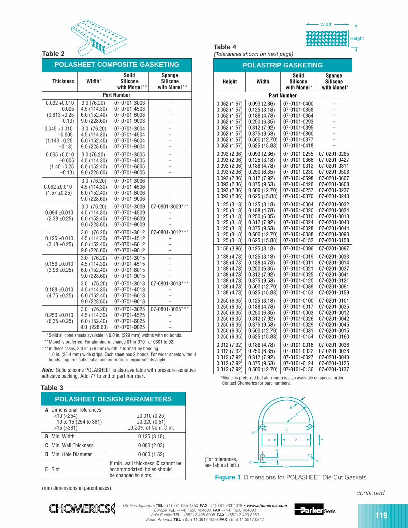
US Headquarters TEL +(1) 781-935-4850 FAX +(1) 781-933-4318 • www.chomerics.comEurope TEL +(44) 1628 404000 FAX +(44) 1628 404090
Asia Pacific TEL +(852) 2 428 8008 FAX +(852) 2 423 8253South America TEL +(55) 11 3917 1099 FAX +(55) 11 3917 0817
119
Width
Height
(mm dimensions in parentheses)
POLASHEET COMPOSITE GASKETING
Thickness Width*Solid
Siliconewith Monel**
SpongeSilicone
with Monel**Part Number
3.0 (76.20)4.5 (114.30)6.0 (152.40)9.0 (228.60)
07-0701-300307-0701-450307-0701-600307-0701-9003
0.045 +0.010–0.005
(1.143 +0.25–0.13)
3.0 (76.20)4.5 (114.30)6.0 (152.40)9.0 (228.60)
07-0701-300407-0701-450407-0701-600407-0701-9004
––––
0.055 +0.010–0.005
(1.40 +0.25–0.13)
3.0 (76.20)4.5 (114.30)6.0 (152.40)9.0 (228.60)
07-0701-300507-0701-450507-0701-600507-0701-9005
––––
0.062 ±0.010(1.57 ±0.25)
07-0701-300607-0701-450607-0701-600607-0701-9006
––––
0.094 ±0.010(2.38 ±0.25)
07-0701-300907-0701-450907-0701-600907-0701-9009
07-0801-3009***–––
0.125 ±0.010(3.18 ±0.25)
07-0701-301207-0701-451207-0701-601207-0701-9012
07-0801-3012***–––
0.156 ±0.010(3.96 ±0.25)
07-0701-301507-0701-451507-0701-601507-0701-9015
––––
0.188 ±0.010(4.75 ±0.25)
07-0701-301807-0701-451807-0701-601807-0701-9018
07-0801-3018***–––
0.250 ±0.010(6.35 ±0.25)
07-0701-302507-0701-452507-0701-602507-0701-9025
07-0801-3025***–––
0.032 +0.010–0.005
(0.813 +0.25–0.13)
––––
3.0 (76.20)4.5 (114.30)6.0 (152.40)9.0 (228.60)3.0 (76.20)4.5 (114.30)6.0 (152.40)9.0 (228.60)3.0 (76.20)4.5 (114.30)6.0 (152.40)9.0 (228.60)3.0 (76.20)4.5 (114.30)6.0 (152.40)9.0 (228.60)3.0 (76.20)4.5 (114.30)6.0 (152.40)9.0 (228.60)3.0 (76.20)4.5 (114.30)6.0 (152.40)9.0 (228.60)
***Solid silicone sheets available in 9.0 in. (229 mm) widths with no bonds.***Monel is preferred. For aluminum, change 01 in 0701 or 0801 to 02.***In these cases, 3.0 in. (76 mm) width is formed by bonding
1.0 in. (25.4 mm) wide strips. Each sheet has 2 bonds. For wider sheets withoutbonds, inquire– substantial minimum order requirements apply.
Table 2Table 4(Tolerances shown on next page)
*Monel is preferred but aluminum is also available on special order .Contact Chomerics for part numbers.
A
B
B AA
AD
C
C
A
E
Figure 1 Dimensions for POLASHEET Die-Cut Gaskets
(For tolerances,see table at left.)
POLASTRIP GASKETING
Height WidthSolid
Siliconewith Monel*
SpongeSilicone
with Monel*Part Number
0.062 (1.57)0.062 (1.57)0.062 (1.57)0.062 (1.57)0.062 (1.57)0.062 (1.57)0.062 (1.57)0.062 (1.57)
0.093 (2.36)0.125 (3.18)0.188 (4.78)0.250 (6.35)0.312 (7.92)0.375 (9.53)0.500 (12.70)0.625 (15.88)
07-0101-040007-0101-035807-0101-036407-0101-029307-0101-039507-0101-030007-0101-037707-0101-0418
––––––––
0.093 (2.36)0.093 (2.36)0.093 (2.36)0.093 (2.36)0.093 (2.36)0.093 (2.36)0.093 (2.36)0.093 (2.36)
0.093 (2.36)0.125 (3.18)0.188 (4.78)0.250 (6.35)0.312 (7.92)0.375 (9.53)0.500 (12.70)0.625 (15.88)
07-0101-025507-0101-036607-0101-031207-0101-023007-0101-059807-0101-042607-0101-025707-0101-0370
07-0201-028507-0201-042707-0201-031107-0201-050807-0201-060707-0201-060807-0201-023707-0201-0243
0.125 (3.18)0.125 (3.18)0.125 (3.18)0.125 (3.18)0.125 (3.18)0.125 (3.18)0.125 (3.18)
0.125 (3.18)0.188 (4.78)0.250 (6.35)0.312 (7.92)0.375 (9.53)0.500 (12.70)0.625 (15.88)
07-0101-000407-0101-002007-0101-001007-0101-002407-0101-002807-0101-008807-0101-0152
07-0201-003207-0201-003407-0201-001307-0201-004007-0201-004407-0201-009007-0201-0158
0.156 (3.96) 0.125 (3.18) 07-0101-0096 07-0201-0097
0.188 (4.78)0.188 (4.78)0.188 (4.78)0.188 (4.78)0.188 (4.78)0.188 (4.78)0.188 (4.78)
0.125 (3.18)0.188 (4.78)0.250 (6.35)0.312 (7.92)0.375 (9.53)0.500 (12.70)0.625 (15.88)
07-0101-001907-0101-001107-0101-002107-0101-002507-0101-012007-0101-008907-0101-0153
07-0201-003307-0201-001407-0201-003707-0201-004107-0201-012107-0201-009107-0201-0159
0.250 (6.35)0.250 (6.35)0.250 (6.35)0.250 (6.35)0.250 (6.35)0.250 (6.35)0.250 (6.35)
0.125 (3.18)0.188 (4.78)0.250 (6.35)0.312 (7.92)0.375 (9.53)0.500 (12.70)0.625 (15.88)
07-0101-010007-0101-001707-0101-000307-0101-002607-0101-002907-0101-003107-0101-0154
07-0201-010107-0201-003507-0201-001207-0201-004207-0201-004507-0201-001507-0201-0160
0.312 (7.92)0.312 (7.92)0.312 (7.92)0.312 (7.92)0.312 (7.92)
0.188 (4.78)0.250 (6.35)0.312 (7.92)0.375 (9.53)0.500 (12.70)
07-0101-001607-0101-002207-0101-002707-0101-012407-0101-0136
07-0201-003607-0201-003807-0201-004307-0201-012507-0201-0137Note: Solid silicone POLASHEET is also available with pressure-sensitive
adhesive backing. Add-77 to end of part number .
Table 3
POLASHEET DESIGN PARAMETERS
A Dimensional Tolerances<10 (<254) ±0.010 (0.25)10 to 15 (254 to 381) ±0.020 (0.51)
>15 (>381) ±0.20% of Nom. Dim.
B Min. Width 0.125 (3.18)
C Min. Wall Thickness 0.080 (2.03)
D Min. Hole Diameter 0.060 (1.52)
If min. wall thickness C cannot beE Slot accommodated, holes should
be changed to slots.
continued
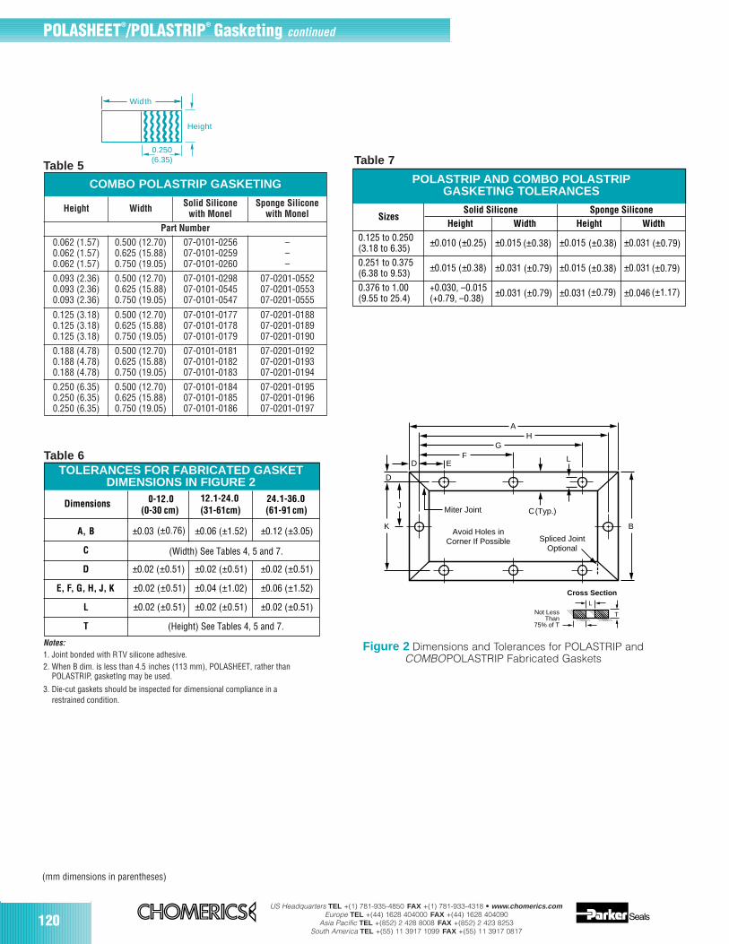
120US Headquarters TEL +(1) 781-935-4850 FAX +(1) 781-933-4318 • www.chomerics.com
Europe TEL +(44) 1628 404000 FAX +(44) 1628 404090Asia Pacific TEL +(852) 2 428 8008 FAX +(852) 2 423 8253
South America TEL +(55) 11 3917 1099 FAX +(55) 11 3917 0817
(mm dimensions in parentheses)
Notes:1. Joint bonded with RTV silicone adhesive.2. When B dim. is less than 4.5 inches (113 mm), POLASHEET, rather than
POLASTRIP, gasketIng may be used.
3. Die-cut gaskets should be inspected for dimensional compliance in arestrained condition.
Table 50.250(6.35)
Width
Height
GH
BK
D
D
E
J
F
A
L
C (Typ.)Miter Joint
Spliced JointOptional
Avoid Holes inCorner If Possible
Dimensions and Tolerancesfor POLASTRIPFabricated Gaskets
T
LNot Less
Than75% of T
Cross Section
POLASTRIP AND COMBO POLASTRIPGASKETING TOLERANCES
SizesSolid Silicone Sponge Silicone
Height Width Height Width0.125 to 0.250(3.18 to 6.35) ±0.010 (±0.25) ±0.015 ±0.015 ±0.031
0.251 to 0.375(6.38 to 9.53) ±0.015 (±0.38) ±0.031 ±0.015 ±0.031
0.376 to 1.00(9.55 to 25.4)
+0.030, –0.015 (+0.79, –0.38) ±0.031 (±0.79) ±0.031 ±0.046
(±0.79)
(±0.38) (±0.38)
(±0.38)
(±0.79)
(±0.79)
(±0.79)
(±1.17)
Dimensions 0-12.0(0-30 cm)
12.1-24.0(31-61cm)
24.1-36.0(61-91 cm)
A, B ±0.03 (±0.76) ±0.06 (±1.52) ±0.12 (±3.05)
C
(Height) See Tables 4, 5 and 7.
(Width) See Tables 4, 5 and 7.
D ±0.02 (±0.51) ±0.02 (±0.51) ±0.02 (±0.51)
E, F, G, H, J, K ±0.02 (±0.51) ±0.04 (±1.02) ±0.06 (±1.52)
L ±0.02 (±0.51) ±0.02 (±0.51) ±0.02 (±0.51)
T
TOLERANCES FOR FABRICATED GASKETDIMENSIONS IN FIGURE 2
Figure 2 Dimensions and Tolerances for POLASTRIP and COMBOPOLASTRIP Fabricated Gaskets
Table 6
Table 7
COMBO POLASTRIP GASKETING
Height Width Solid Siliconewith Monel
Sponge Siliconewith Monel
Part Number
0.062 (1.57)0.062 (1.57)0.062 (1.57)
0.500 (12.70)0.625 (15.88)0.750 (19.05)
07-0101-025607-0101-025907-0101-0260
–––
0.093 (2.36)0.093 (2.36)0.093 (2.36)
0.500 (12.70)0.625 (15.88)0.750 (19.05)
07-0101-029807-0101-054507-0101-0547
07-0201-055207-0201-055307-0201-0555
0.125 (3.18)0.125 (3.18)0.125 (3.18)
0.500 (12.70)0.625 (15.88)0.750 (19.05)
07-0101-017707-0101-017807-0101-0179
07-0201-018807-0201-018907-0201-0190
0.188 (4.78)0.188 (4.78)0.188 (4.78)
0.500 (12.70)0.625 (15.88)0.750 (19.05)
07-0101-018107-0101-018207-0101-0183
07-0201-019207-0201-019307-0201-0194
0.250 (6.35)0.250 (6.35)0.250 (6.35)
0.500 (12.70)0.625 (15.88)0.750 (19.05)
07-0101-018407-0101-018507-0101-0186
07-0201-019507-0201-019607-0201-0197
POLASHEET®/POLASTRIP® Gasketing continued
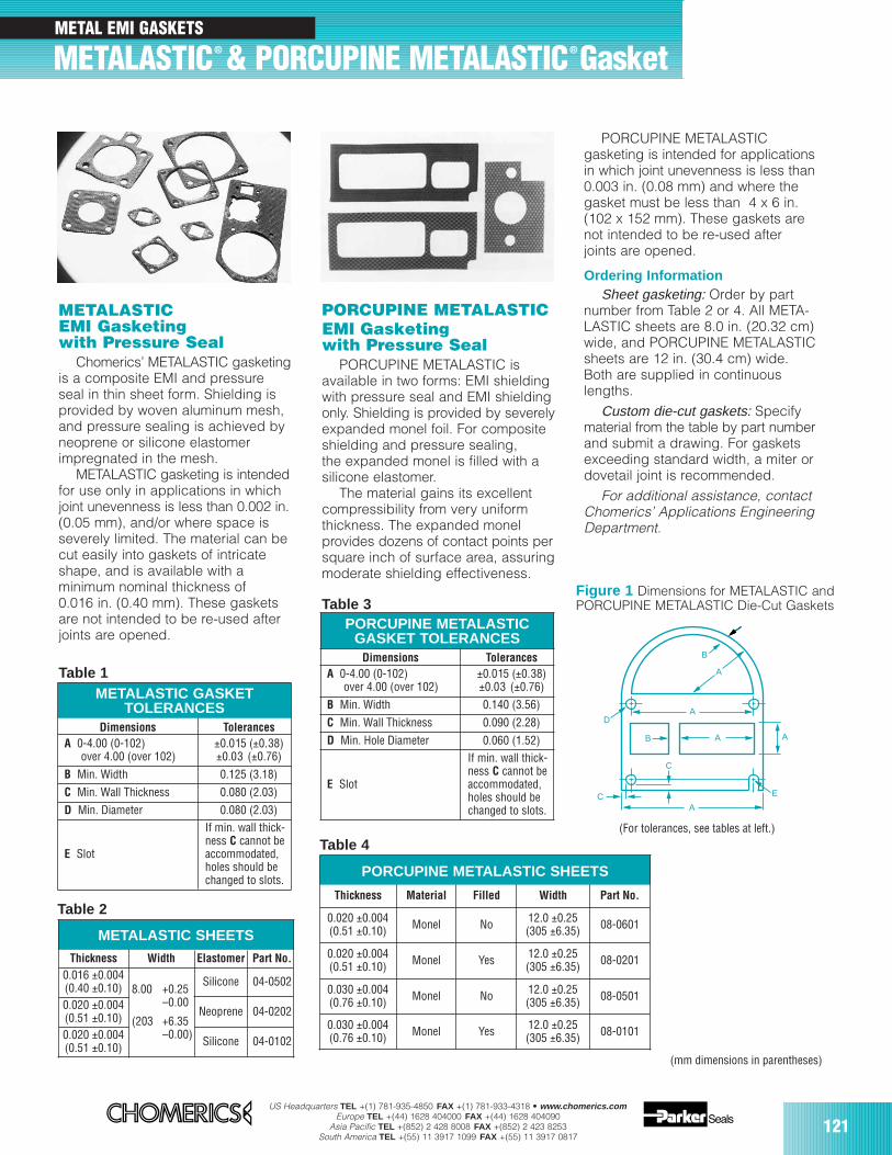
US Headquarters TEL +(1) 781-935-4850 FAX +(1) 781-933-4318 • www.chomerics.comEurope TEL +(44) 1628 404000 FAX +(44) 1628 404090
Asia Pacific TEL +(852) 2 428 8008 FAX +(852) 2 423 8253South America TEL +(55) 11 3917 1099 FAX +(55) 11 3917 0817
121
METAL EMI GASKETS
(mm dimensions in parentheses)
METALASTIC® & PORCUPINE METALASTIC® Gasket
METALASTICEMI Gasketingwith Pressure Seal
Chomerics’ METALASTIC gasketingis a composite EMI and pressureseal in thin sheet form. Shielding isprovided by woven aluminum mesh,and pressure sealing is achieved byneoprene or silicone elastomerimpregnated in the mesh.
METALASTIC gasketing is intendedfor use only in applications in whichjoint unevenness is less than 0.002 in.(0.05 mm), and/or where space isseverely limited. The material can becut easily into gaskets of intricateshape, and is available with aminimum nominal thickness of0.016 in. (0.40 mm). These gasketsare not intended to be re-used afterjoints are opened.
METALASTIC GASKETTOLERANCES
Dimensions TolerancesA 0-4.00 (0-102)
over 4.00 (over 102)±0.015 (±0.38)±0.03 (±0.76)
B Min. Width 0.125 (3.18)
C Min. Wall Thickness 0.080 (2.03)
D Min. Diameter 0.080 (2.03)
E Slot
If min. wall thick-ness C cannot beaccommodated,holes should bechanged to slots.
METALASTIC SHEETS
Thickness Width Elastomer Part No.
Silicone 04-0502
Neoprene 04-0202
Silicone 04-0102
0.016 ±0.004(0.40 ±0.10)0.020 ±0.004(0.51 ±0.10)0.020 ±0.004(0.51 ±0.10)
Table 2
A
B
B AA
AD
C
C
A
E
PORCUPINE METALASTICEMI Gasketingwith Pressure Seal
PORCUPINE METALASTIC isavailable in two forms: EMI shieldingwith pressure seal and EMI shieldingonly. Shielding is provided by severelyexpanded monel foil. For compositeshielding and pressure sealing,the expanded monel is filled with asilicone elastomer.
The material gains its excellentcompressibility from very uniformthickness. The expanded monelprovides dozens of contact points persquare inch of surface area, assuringmoderate shielding effectiveness.
PORCUPINE METALASTIC SHEETS
Thickness Material Filled Width Part No.
0.020 ±0.004(0.51 ±0.10) Monel No 12.0 ±0.25
(305 ±6.35) 08-0601
0.020 ±0.004(0.51 ±0.10) Monel Yes 12.0 ±0.25
(305 ±6.35) 08-0201
0.030 ±0.004(0.76 ±0.10) Monel No 12.0 ±0.25
(305 ±6.35) 08-0501
0.030 ±0.004(0.76 ±0.10) Monel Yes 12.0 ±0.25
(305 ±6.35) 08-0101
Table 4
PORCUPINE METALASTICGASKET TOLERANCES
Dimensions TolerancesA 0-4.00 (0-102)
over 4.00 (over 102)±0.015 (±0.38)±0.03 (±0.76)
B Min. Width 0.140 (3.56)
C Min. Wall Thickness 0.090 (2.28)
D Min. Hole Diameter 0.060 (1.52)
E Slot
If min. wall thick-ness C cannot beaccommodated,holes should bechanged to slots.
8.00 +0.25–0.00
(203 +6.35–0.00)
PORCUPINE METALASTICgasketing is intended for applicationsin which joint unevenness is less than0.003 in. (0.08 mm) and where thegasket must be less than 4 x 6 in.(102 x 152 mm). These gaskets arenot intended to be re-used afterjoints are opened.
Ordering InformationSheet gasketing: Order by part
number from Table 2 or 4. All META-LASTIC sheets are 8.0 in. (20.32 cm)wide, and PORCUPINE METALASTICsheets are 12 in. (30.4 cm) wide.Both are supplied in continuouslengths.
Custom die-cut gaskets: Specifymaterial from the table by part numberand submit a drawing. For gasketsexceeding standard width, a miter ordovetail joint is recommended.
For additional assistance, contactChomerics’ Applications EngineeringDepartment.
(For tolerances, see tables at left.)
Table 1
Table 3Figure 1 Dimensions for METALASTIC andPORCUPINE METALASTIC Die-Cut Gaskets
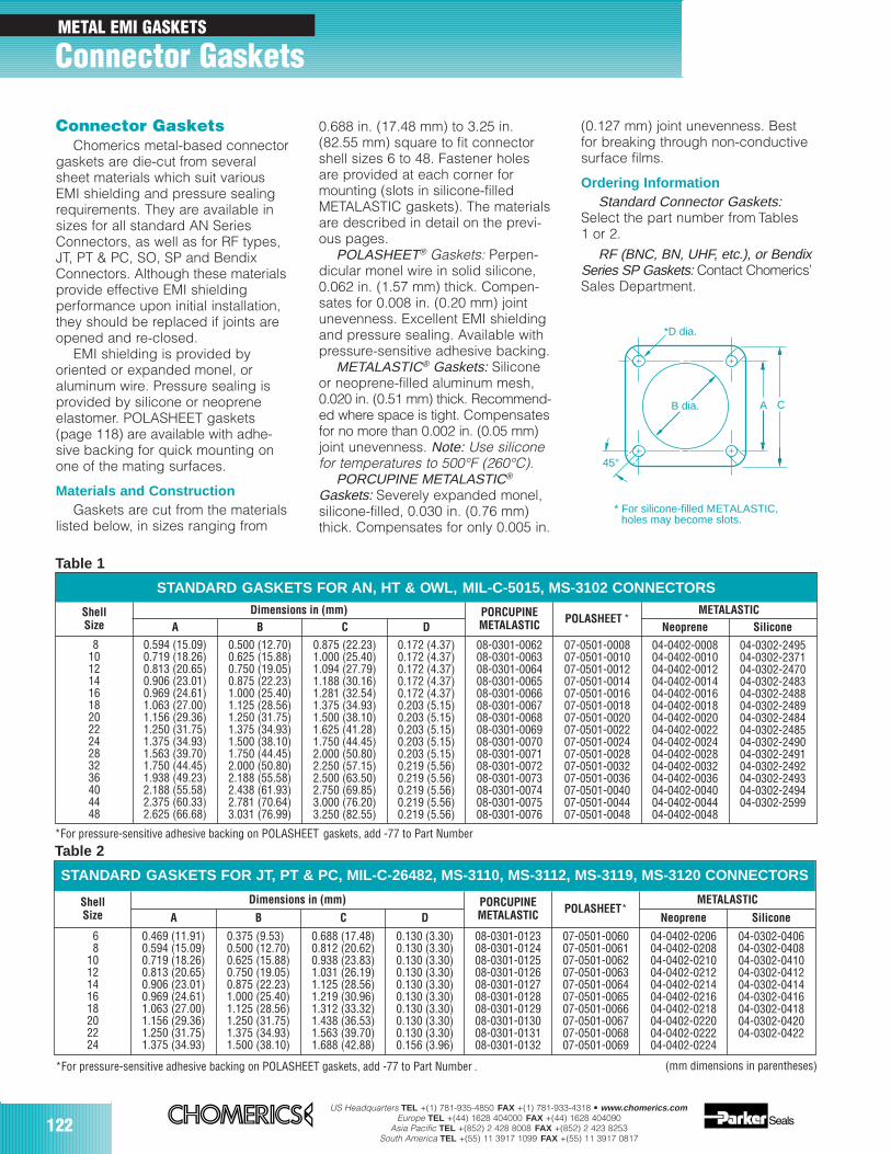
122US Headquarters TEL +(1) 781-935-4850 FAX +(1) 781-933-4318 • www.chomerics.com
Europe TEL +(44) 1628 404000 FAX +(44) 1628 404090Asia Pacific TEL +(852) 2 428 8008 FAX +(852) 2 423 8253
South America TEL +(55) 11 3917 1099 FAX +(55) 11 3917 0817
Connector GasketsChomerics metal-based connector
gaskets are die-cut from severalsheet materials which suit variousEMI shielding and pressure sealingrequirements. They are available insizes for all standard AN SeriesConnectors, as well as for RF types,JT, PT & PC, SO, SP and BendixConnectors. Although these materialsprovide effective EMI shieldingperformance upon initial installation,they should be replaced if joints areopened and re-closed.
EMI shielding is provided byoriented or expanded monel, oraluminum wire. Pressure sealing isprovided by silicone or neopreneelastomer. POLASHEET gaskets(page 118) are available with adhe-sive backing for quick mounting onone of the mating surfaces.
Materials and ConstructionGaskets are cut from the materials
listed below, in sizes ranging from
0.688 in. (17.48 mm) to 3.25 in.(82.55 mm) square to fit connectorshell sizes 6 to 48. Fastener holesare provided at each corner formounting (slots in silicone-filledMETALASTIC gaskets). The materialsare described in detail on the previ-ous pages.
POLASHEET® Gaskets: Perpen-dicular monel wire in solid silicone,0.062 in. (1.57 mm) thick. Compen-sates for 0.008 in. (0.20 mm) jointunevenness. Excellent EMI shieldingand pressure sealing. Available withpressure-sensitive adhesive backing.
METALASTIC® Gaskets: Silicone or neoprene-filled aluminum mesh,0.020 in. (0.51 mm) thick. Recommend-ed where space is tight. Compensatesfor no more than 0.002 in. (0.05 mm)joint unevenness. Note: Use siliconefor temperatures to 500°F (260°C).
PORCUPINE METALASTIC®
Gaskets: Severely expanded monel,silicone-filled, 0.030 in. (0.76 mm)thick. Compensates for only 0.005 in.
(0.127 mm) joint unevenness. Bestfor breaking through non-conductivesurface films.
Ordering InformationStandard Connector Gaskets:
Select the part number from Tables1 or 2.
RF (BNC, BN, UHF, etc.), or BendixSeries SP Gaskets: Contact Chomerics’Sales Department.
A C
*D dia.
45°
B dia.
* For silicone-filled METALASTIC, holes may become slots.
*For pressure-sensitive adhesive backing on POLASHEET gaskets, add -77 to Part Number
(mm dimensions in parentheses)
STANDARD GASKETS FOR AN, HT & OWL, MIL-C-5015, MS-3102 CONNECTORS
ShellSize
Dimensions in (mm) PORCUPINEMETALASTIC POLASHEET *
METALASTICA B C D Neoprene Silicone
81012141618202224283236404448
0.594 (15.09)0.719 (18.26)0.813 (20.65)0.906 (23.01)0.969 (24.61)1.063 (27.00)1.156 (29.36)1.250 (31.75)1.375 (34.93)1.563 (39.70)1.750 (44.45)1.938 (49.23)2.188 (55.58)2.375 (60.33)2.625 (66.68)
0.500 (12.70)0.625 (15.88)0.750 (19.05)0.875 (22.23)1.000 (25.40)1.125 (28.56)1.250 (31.75)1.375 (34.93)1.500 (38.10)1.750 (44.45)2.000 (50.80)2.188 (55.58)2.438 (61.93)2.781 (70.64)3.031 (76.99)
0.875 (22.23)1.000 (25.40)1.094 (27.79)1.188 (30.16)1.281 (32.54)1.375 (34.93)1.500 (38.10)1.625 (41.28)1.750 (44.45)2.000 (50.80)2.250 (57.15)2.500 (63.50)2.750 (69.85)3.000 (76.20)3.250 (82.55)
0.172 (4.37)0.172 (4.37)0.172 (4.37)0.172 (4.37)0.172 (4.37)0.203 (5.15)0.203 (5.15)0.203 (5.15)0.203 (5.15)0.203 (5.15)0.219 (5.56)0.219 (5.56)0.219 (5.56)0.219 (5.56)0.219 (5.56)
08-0301-006208-0301-006308-0301-006408-0301-006508-0301-006608-0301-006708-0301-006808-0301-006908-0301-007008-0301-007108-0301-007208-0301-007308-0301-007408-0301-007508-0301-0076
07-0501-000807-0501-001007-0501-001207-0501-001407-0501-001607-0501-001807-0501-002007-0501-002207-0501-002407-0501-002807-0501-003207-0501-003607-0501-004007-0501-004407-0501-0048
04-0402-000804-0402-001004-0402-001204-0402-001404-0402-001604-0402-001804-0402-002004-0402-002204-0402-002404-0402-002804-0402-003204-0402-003604-0402-004004-0402-004404-0402-0048
04-0302-249504-0302-237104-0302-247004-0302-248304-0302-248804-0302-248904-0302-248404-0302-248504-0302-249004-0302-249104-0302-249204-0302-249304-0302-249404-0302-2599
STANDARD GASKETS FOR JT, PT & PC, MIL-C-26482, MS-3110, MS-3112, MS-3119, MS-3120 CONNECTORS
ShellSize
Dimensions in (mm) PORCUPINEMETALASTIC POLASHEET*
METALASTIC
A B C D Neoprene Silicone
68
1012141618202224
0.469 (11.91)0.594 (15.09)0.719 (18.26)0.813 (20.65)0.906 (23.01)0.969 (24.61)1.063 (27.00)1.156 (29.36)1.250 (31.75)1.375 (34.93)
0.375 (9.53)0.500 (12.70)0.625 (15.88)0.750 (19.05)0.875 (22.23)1.000 (25.40)1.125 (28.56)1.250 (31.75)1.375 (34.93)1.500 (38.10)
0.688 (17.48)0.812 (20.62)0.938 (23.83)1.031 (26.19)1.125 (28.56)1.219 (30.96)1.312 (33.32)1.438 (36.53)1.563 (39.70)1.688 (42.88)
0.130 (3.30)0.130 (3.30)0.130 (3.30)0.130 (3.30)0.130 (3.30)0.130 (3.30)0.130 (3.30)0.130 (3.30)0.130 (3.30)0.156 (3.96)
08-0301-012308-0301-012408-0301-012508-0301-012608-0301-012708-0301-012808-0301-012908-0301-013008-0301-013108-0301-0132
07-0501-006007-0501-006107-0501-006207-0501-006307-0501-006407-0501-006507-0501-006607-0501-006707-0501-006807-0501-0069
04-0402-020604-0402-020804-0402-021004-0402-021204-0402-021404-0402-021604-0402-021804-0402-022004-0402-022204-0402-0224
04-0302-040604-0302-040804-0302-041004-0302-041204-0302-041404-0302-041604-0302-041804-0302-042004-0302-0422
Table 1
Table 2
METAL EMI GASKETS
Connector Gaskets
*For pressure-sensitive adhesive backing on POLASHEET gaskets, add -77 to Part Number .
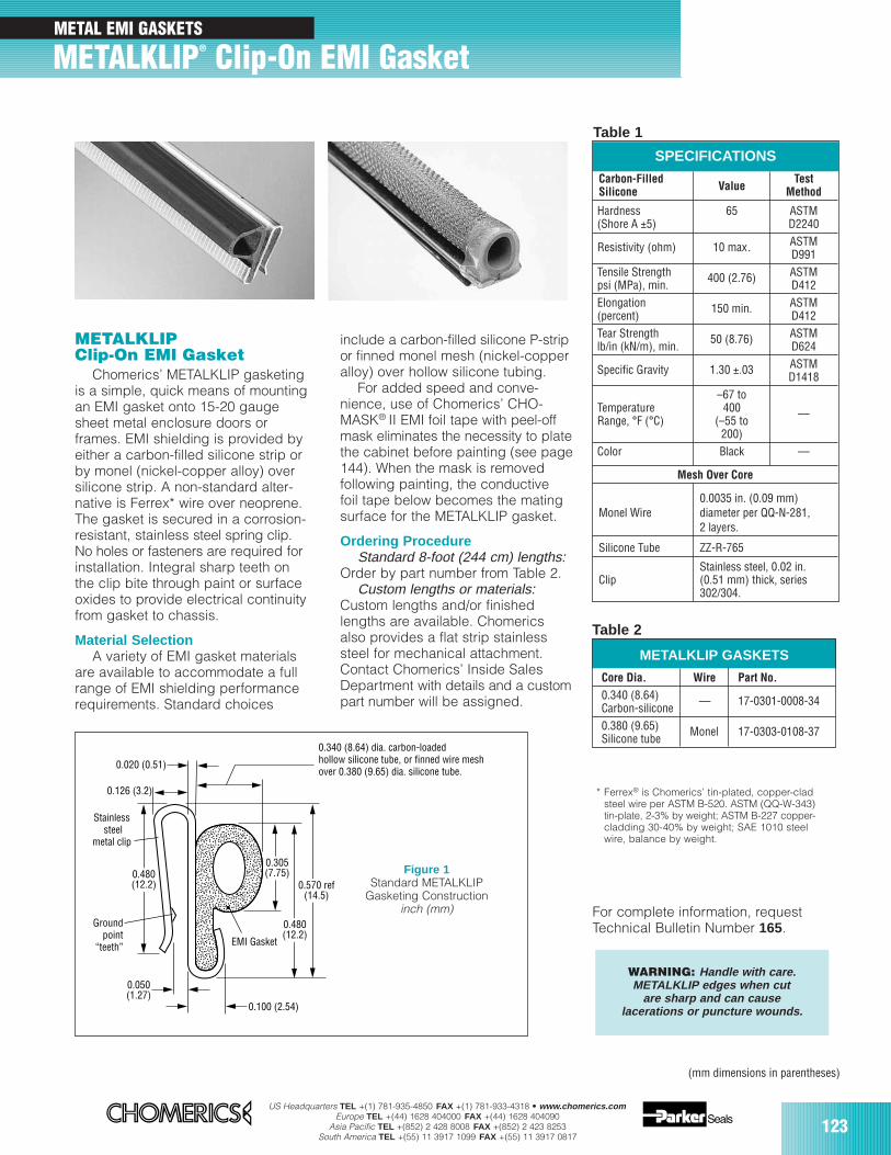
US Headquarters TEL +(1) 781-935-4850 FAX +(1) 781-933-4318 • www.chomerics.comEurope TEL +(44) 1628 404000 FAX +(44) 1628 404090
Asia Pacific TEL +(852) 2 428 8008 FAX +(852) 2 423 8253South America TEL +(55) 11 3917 1099 FAX +(55) 11 3917 0817
123
METALKLIP® Clip-On EMI Gasket
METALKLIPClip-On EMI Gasket
Chomerics’ METALKLIP gasketingis a simple, quick means of mountingan EMI gasket onto 15-20 gaugesheet metal enclosure doors orframes. EMI shielding is provided byeither a carbon-filled silicone strip orby monel (nickel-copper alloy) oversilicone strip. A non-standard alter-native is Ferrex* wire over neoprene.The gasket is secured in a corrosion-resistant, stainless steel spring clip.No holes or fasteners are required forinstallation. Integral sharp teeth onthe clip bite through paint or surfaceoxides to provide electrical continuityfrom gasket to chassis.
Material SelectionA variety of EMI gasket materials
are available to accommodate a fullrange of EMI shielding performancerequirements. Standard choices
For complete information, requestTechnical Bulletin Number 165.
0.340 (8.64) dia. carbon-loadedhollow silicone tube, or finned wire mesh over 0.380 (9.65) dia. silicone tube.
0.305(7.75)
0.570 ref(14.5)
0.480(12.2)
0.480(12.2)
0.050(1.27)
EMI Gasket
0.020 (0.51)
0.126 (3.2)
0.100 (2.54)
Stainless steel
metal clip
Ground point
“teeth”
include a carbon-filled silicone P-stripor finned monel mesh (nickel-copperalloy) over hollow silicone tubing.
For added speed and conve-nience, use of Chomerics’ CHO-MASK® II EMI foil tape with peel-offmask eliminates the necessity to platethe cabinet before painting (see page144). When the mask is removedfollowing painting, the conductivefoil tape below becomes the matingsurface for the METALKLIP gasket.
Ordering ProcedureStandard 8-foot (244 cm) lengths:
Order by part number from Table 2.Custom lengths or materials:
Custom lengths and/or finishedlengths are available. Chomericsalso provides a flat strip stainlesssteel for mechanical attachment.Contact Chomerics’ Inside SalesDepartment with details and a custompart number will be assigned.
WARNING: Handle with care.METALKLIP edges when cut
are sharp and can causelacerations or puncture wounds.
METALKLIP GASKETS
Core Dia. Wire Part No.
0.340 (8.64)Carbon-silicone
–– 17-0301-0008-34
0.380 (9.65) Monel 17-0303-0108-37Silicone tube
** Ferrex® is Chomerics’ tin-plated, copper-cladsteel wire per ASTM B-520. ASTM (QQ-W-343)tin-plate, 2-3% by weight; ASTM B-227 copper-cladding 30-40% by weight; SAE 1010 steelwire, balance by weight.
SPECIFICATIONS
Carbon-Filled Test Silicone Value Method
Hardness 65 ASTM(Shore A ±5) D2240
Resistivity (ohm) 10 max. ASTMD991
Tensile Strength 400 (2.76) ASTMpsi (MPa), min. D412Elongation 150 min. ASTM(percent) D412Tear Strength 50 (8.76) ASTMlb/in (kN/m), min. D624
Specific Gravity 1.30 ±.03 ASTMD1418
–67 toTemperature 400 ––Range, °F (°C) (–55 to
200)Color Black —
Mesh Over Core
0.0035 in. (0.09 mm)Monel Wire diameter per QQ-N-281,
2 layers.
Silicone Tube ZZ-R-765
Stainless steel, 0.02 in.Clip (0.51 mm) thick, series
302/304.
Figure 1Standard METALKLIP
Gasketing Constructioninch (mm)
Table 2
(mm dimensions in parentheses)
Table 1
METAL EMI GASKETS
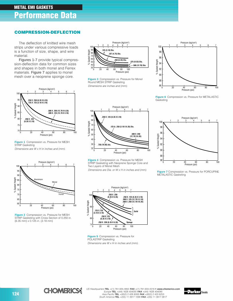
124US Headquarters TEL +(1) 781-935-4850 FAX +(1) 781-933-4318 • www.chomerics.com
Europe TEL +(44) 1628 404000 FAX +(44) 1628 404090Asia Pacific TEL +(852) 2 428 8008 FAX +(852) 2 423 8253
South America TEL +(55) 11 3917 1099 FAX +(55) 11 3917 0817
METAL EMI GASKETS
Performance Data
75
700 20 40 60 80 100
1 2 765
80
85
90
95
100
% G
aske
t Hei
ght
.250 X .250 (6.35 X 6.35).125 X .125 (3.18 X 3.18)
.500 X .250 (12.70 X 6.35)
.500 X .125 (12.70 X 3.18)
Pressure (psi)
.250 X .125(6.35 X 3.18)
3 4Pressure (kg/cm2)
Figure 1 Compression vs. Pressure for MESHSTRIP GasketingDimensions are W x H in inches and (mm).
65
600 20 40 60 80 100
1 2 765
70
75
80
85
90
95
100
% G
aske
t Hei
ght
Pressure (psi)
3 4Pressure (kg/cm2)
AluminiumMonel
Ferrex
Figure 2 Compression vs. Pressure for MESHSTRIP Gasketing with Cross Section of 0.250 in.(6.35 mm) x 0.125 in. (3.18 mm)
4030
0 20 40 60 80 100
1 2 3 4 765
5060708090
100
% G
aske
t Hei
ght
Pressure (psi)
Pressure (kg/cm2)
.125 (3.18) Dia.
.187 (4.75) Dia.
.375 (9.53) Dia.
.500 (12.70) Dia.
.250 (6.35) Dia.
Figure 3 Compression vs. Pressure for MonelRound MESH STRIP GasketingDimensions are inches and (mm).
30
200 20 40 60 80 100
1 2 765
40
50
60
70
80
90
100
% G
aske
t Hei
ght
Pressure (psi)
3 4Pressure (kg/cm2)
.125 & .250 (3.18 X 6.35) Dia.
.250 X .125 (6.35 X 3.18)
.500 X .250(12.70 X 6.35)
.750 (19.05) dia.
Figure 4 Compression vs. Pressure for MESHSTRIP Gasketing with Neoprene Sponge Core andTwo Layers of Monel MeshDimensions are Dia. or W x H in inches and (mm).
0 20 40 60 80 100
1 2 3 4 765
74
90
80
100
% G
aske
t Hei
ght
Pressure (psi)
Pressure (kg/cm2)
.250 X .125 (6.35 X 3.18).500 X .125 (12.70 X 3.18).500 X .250 (12.70 X 6.35)
.
.125 X .125(3.18 X 3.18)
.250 X .125(6.35 X 3.18)
.250 X .250 (6.35 X 6.35)
.250 X .250(6.35 X 6.35)
Solid
Sponge
Figure 5 Compression vs. Pressure forPOLASTRIP GasketingDimensions are W x H in inches and (mm).
88
860 20 40 60 80 100
1 2 765
90
92
94
96
98
100
% G
aske
t Hei
ght
Pressure (psi)
3 4Pressure (kg/cm2)
Figure 6 Compression vs. Pressure for METALASTICGasketing
860 20 80 100
1 2 765
% G
aske
t Hei
ght
3 4Pressure (kg/cm2)
88
90
92
94
96
98
100
40 60Pressure (psi)
Figure 7 Compression vs. Pressure for PORCUPINEMETALASTIC Gasketing
COMPRESSION-DEFLECTION
The deflection of knitted wire meshstrips under various compressive loadsis a function of size, shape, and wirematerial.
Figures 1-7 provide typical compres-sion-deflection data for common sizesand shapes in both monel and Ferrexmaterials. Figure 7 applies to monelmesh over a neoprene sponge core.
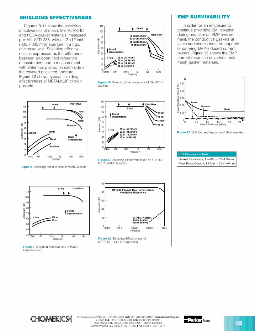
US Headquarters TEL +(1) 781-935-4850 FAX +(1) 781-933-4318 • www.chomerics.comEurope TEL +(44) 1628 404000 FAX +(44) 1628 404090
Asia Pacific TEL +(852) 2 428 8008 FAX +(852) 2 423 8253South America TEL +(55) 11 3917 1099 FAX +(55) 11 3917 0817
125
Figures 8-11 show the shieldingeffectiveness of mesh, METALASTICand POLA gasket materials, measuredper MIL-STD-285, with a 12 x12 inch(305 x 305 mm) aperture in a rigidenclosure wall. Shielding effective-ness is expressed as the differencebetween an open-field referencemeasurement and a measurementwith antennas placed on each side ofthe covered gasketed aperture.Figure 12 shows typical shieldingeffectiveness of METALKLIP clip-ongaskets.
In order for an enclosure tocontinue providing EMI isolationduring and after an EMP environ-ment, the conductive gaskets atjoints and seams must be capableof carrying EMP-induced currentpulses. Figure 13 shows the EMPcurrent response of various metalmesh gasket materials.
30
40
50
60
70
80
90
100
110
120
Atte
nuat
ion
(dB)
10kHz 100 1MHz 10 100 1GHzFrequency
H Field
E Field
Ferrex
Ferrex
Monel
Monel
Aluminum
Aluminum
Plane Wave
BeyondInstrumentation
Figure 8 Shielding Effectiveness of Mesh Gaskets
30
40
50
60
70
80
90
100
110
Atte
nuat
ion
(dB)
10kHz 100 1MHz 10 100 1GHzFrequency
H Field
E Field Plane Wave
BeyondInstrumentation
100 psi20 psi
Figure 9 Shielding Effectiveness of POLAGaskets (solid)
30
40
50
60
70
80
90
100
110
Atte
nuat
ion
(dB)
10kHz 100 1MHz 10 100 1GHzFrequency
H Field
E Field
Plane Wave
BeyondInstrumentation
75 psi (51.7N/cm2)
50 psi (34.5N/cm2)
20 psi (13.8N/cm2)
10 psi (6.9N/cm2)
75 psi (51.7N/cm2)
50 psi (34.5N/cm2)20 psi (13.8N/cm2)
10 psi (6.9N/cm2)
Figure 10 Shielding Effectiveness of METALASTICGaskets
30
20
40
50
60
70
80
90
100
110At
tenu
atio
n (d
B)
10kHz 100 1MHz 10 100 1GHzFrequency
H Field
Plane Wave
E Field
BeyondInstrumentation
75 psi (51.7N/cm2)
50 psi (34.5N/cm2)20 psi (13.8N/cm2)
10 psi (6.9N/cm2)
75 psi
50 psi
20 psi
10 psi
Figure 11 Shielding Effectiveness of PORCUPINEMETALASTIC Gaskets
20
0
40
60
80
100
Atte
nuat
ion
(dB)
100kHz 1MHz 10MHz 100MHz 1GHzFrequency
METALKLIP Gasket, Monel or Ferrex MeshOver Hollow Silicone Core
METALKLIP Gasket,Carbon-LoadedHollow Silicone
Figure 12 Shielding Effectiveness ofMETALKLIP Clip-On Gasketing
0.05
0
0.10
0.15
0.20
0.25
Gas
ket R
esis
tanc
e (Ω
/in. X
10–
3 )
Peak Pulse Current (kA/in.)0 0.5 1.0 1.5 2.0 2.5
Monel
Ferrex
Aluminum
Figure 13 EMP Current Response of Mesh Gaskets
Unit Conversion Note:
Gasket Resistance, 1 mΩ/in. = 25.4 Ω/mmPeak Pulse Current, 1 kA/in. = 25.4 kA/mm
SHIELDING EFFECTIVENESS EMP SURVIVABILITY
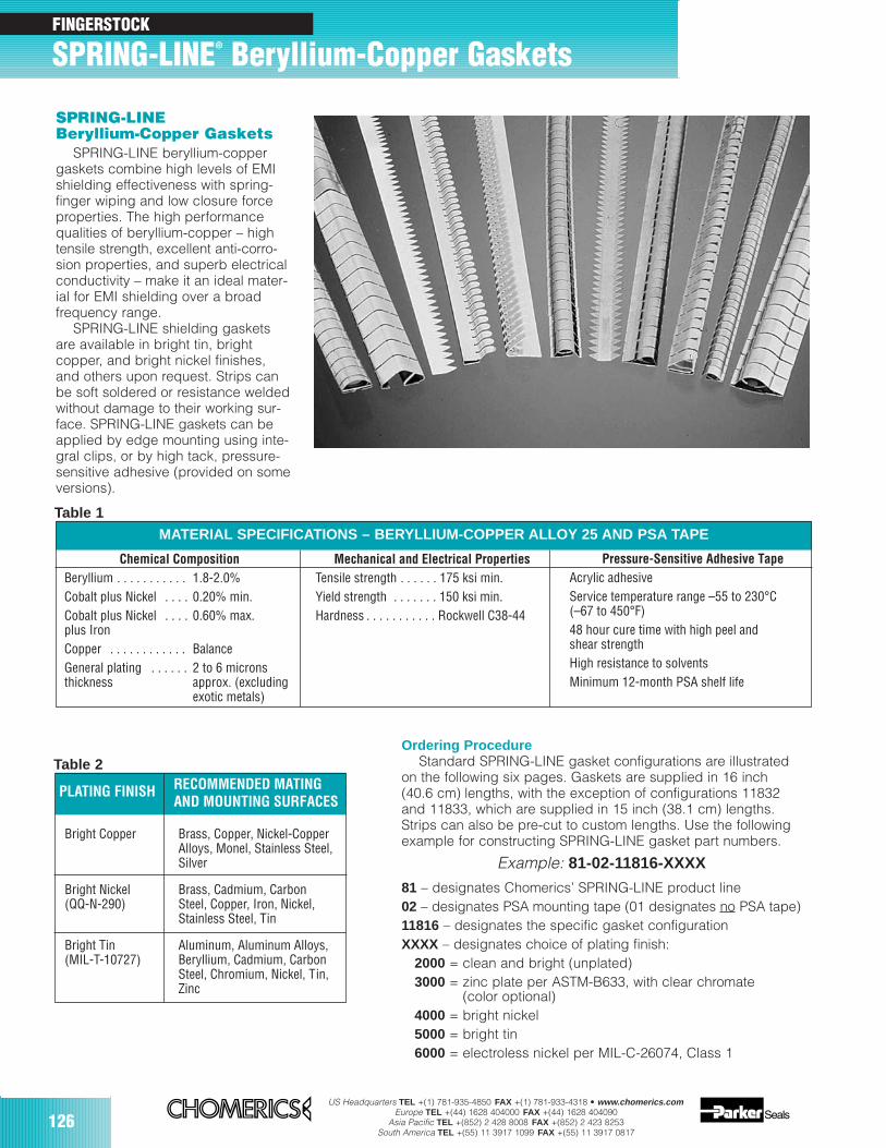
126US Headquarters TEL +(1) 781-935-4850 FAX +(1) 781-933-4318 • www.chomerics.com
Europe TEL +(44) 1628 404000 FAX +(44) 1628 404090Asia Pacific TEL +(852) 2 428 8008 FAX +(852) 2 423 8253
South America TEL +(55) 11 3917 1099 FAX +(55) 11 3917 0817
FINGERSTOCK
SPRING-LINE® Beryllium-Copper Gaskets
SPRING-LINEBeryllium-Copper Gaskets
SPRING-LINE beryllium-coppergaskets combine high levels of EMIshielding effectiveness with spring-finger wiping and low closure forceproperties. The high performancequalities of beryllium-copper – hightensile strength, excellent anti-corro-sion properties, and superb electricalconductivity – make it an ideal mater-ial for EMI shielding over a broadfrequency range.
SPRING-LINE shielding gasketsare available in bright tin, brightcopper, and bright nickel finishes,and others upon request. Strips canbe soft soldered or resistance weldedwithout damage to their working sur-face. SPRING-LINE gaskets can beapplied by edge mounting using inte-gral clips, or by high tack, pressure-sensitive adhesive (provided on someversions).
Chemical CompositionBeryllium . . . . . . . . . . . 1.8-2.0%Cobalt plus Nickel . . . . 0.20% min.Cobalt plus Nickel . . . . 0.60% max.plus IronCopper . . . . . . . . . . . . BalanceGeneral plating . . . . . . 2 to 6 micronsthickness approx. (excluding
exotic metals)
Mechanical and Electrical PropertiesTensile strength . . . . . . 175 ksi min.Yield strength . . . . . . . 150 ksi min.Hardness . . . . . . . . . . . Rockwell C38-44
Pressure-Sensitive Adhesive TapeAcrylic adhesiveService temperature range –55 to 230°C(–67 to 450°F)48 hour cure time with high peel andshear strengthHigh resistance to solventsMinimum 12-month PSA shelf life
MATERIAL SPECIFICATIONS – BERYLLIUM-COPPER ALLOY 25 AND PSA TAPE
Ordering ProcedureStandard SPRING-LINE gasket configurations are illustrated
on the following six pages. Gaskets are supplied in 16 inch(40.6 cm) lengths, with the exception of configurations 11832and 11833, which are supplied in 15 inch (38.1 cm) lengths.Strips can also be pre-cut to custom lengths. Use the followingexample for constructing SPRING-LINE gasket part numbers.
Example: 81-02-11816-XXXX
81 – designates Chomerics’ SPRING-LINE product line02 – designates PSA mounting tape (01 designates no PSA tape)11816 – designates the specific gasket configurationXXXX – designates choice of plating finish:
2000 = clean and bright (unplated)3000 = zinc plate per ASTM-B633, with clear chromate
(color optional)4000 = bright nickel5000 = bright tin6000 = electroless nickel per MIL-C-26074, Class 1
Table 1
Bright Copper Brass, Copper, Nickel-Copper Alloys, Monel, Stainless Steel,Silver
Bright Nickel Brass, Cadmium, Carbon(QQ-N-290) Steel, Copper, Iron, Nickel,
Stainless Steel, Tin
Bright Tin Aluminum, Aluminum Alloys,(MIL-T-10727) Beryllium, Cadmium, Carbon
Steel, Chromium, Nickel, Tin, Zinc
PLATING FINISH RECOMMENDED MATINGAND MOUNTING SURFACES
Table 2
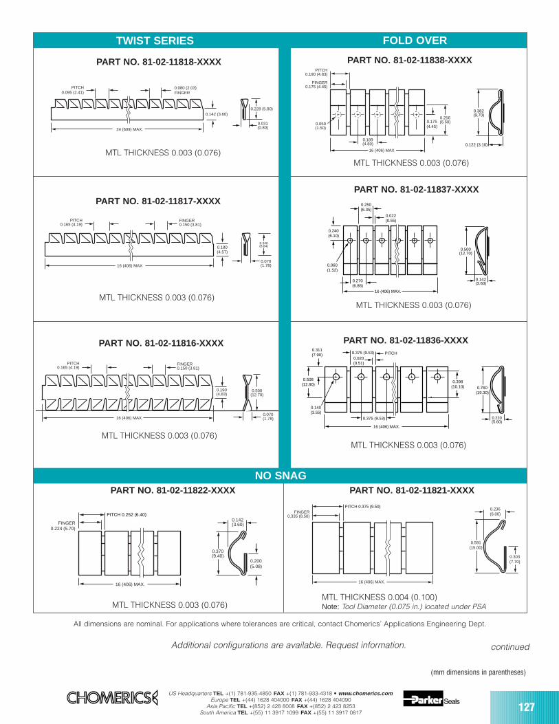
US Headquarters TEL +(1) 781-935-4850 FAX +(1) 781-933-4318 • www.chomerics.comEurope TEL +(44) 1628 404000 FAX +(44) 1628 404090
Asia Pacific TEL +(852) 2 428 8008 FAX +(852) 2 423 8253South America TEL +(55) 11 3917 1099 FAX +(55) 11 3917 0817
127
PART NO. 81-02-11816-XXXX
FINGER0.150 (3.81)
PITCH0.165 (4.19)
16 (406) MAX
0.190(4.83)
0.500(12.70)
0.070 (1.78)
MTL THICKNESS 0.003 (0.076)
PART NO. 81-02-11817-XXXX
MTL THICKNESS 0.003 (0.076)
0.180(4.57)
0.070 (1.78)
FINGER0.150 (3.81)
PITCH0.165 (4.19)
16 (406) MAX
0.340(8.64)
All dimensions are nominal. For applications where tolerances are critical, contact Chomerics’ Applications Engineering Dept.
continued
PART NO. 81-02-11818-XXXX
PITCH0.095 (2.41)
0.080 (2.03)FINGER
0.142 (3.60)0.228 (5.80)
0.031(0.80)24 (609) MAX.
MTL THICKNESS 0.003 (0.076)
PART NO. 81-02-11838-XXXX
FINGER0.175 (4.45)
PITCH0.190 (4.83)
0.189 (4.80)
0.059(1.50)
0.175(4.45)
0.256(6.50)
16 (406) MAX
0.382(9.70)
0.122 (3.10)
MTL THICKNESS 0.003 (0.076)
PART NO. 81-02-11821-XXXX
FINGER0.335 (8.50)
0.236(6.00)
0.591(15.00)
0.303(7.70)
16 (406) MAX.
PITCH 0.375 (9.50)
MTL THICKNESS 0.004 (0.100)Note: Tool Diameter (0.075 in.) located under PSA
PART NO. 81-02-11822-XXXX
MTL THICKNESS 0.003 (0.076)
FINGER0.224 (5.70)
0.142(3.60)
0.200(5.08)
0.370(9.40)
16 (406) MAX.
PITCH 0.252 (6.40)
PART NO. 81-02-11836-XXXX
0.508(12.90)
0.398(10.10)
0.311(7.90) 0.375 (9.53)
0.020(0.51)
0.140(3.55)
PITCH
0.760(19.30)
0.375 (9.53)
16 (406) MAX.
0.220(5.60)
MTL THICKNESS 0.003 (0.076)
PART NO. 81-02-11837-XXXX
MTL THICKNESS 0.003 (0.076)
0.250(6.35)
0.240(6.10)
0.270(6.86)
0.060(1.52)
16 (406) MAX.
0.500(12.70)
0.142(3.60)
0.022(0.55)
TWIST SERIES FOLD OVER
NO SNAG
Additional configurations are available. Request information.
(mm dimensions in parentheses)
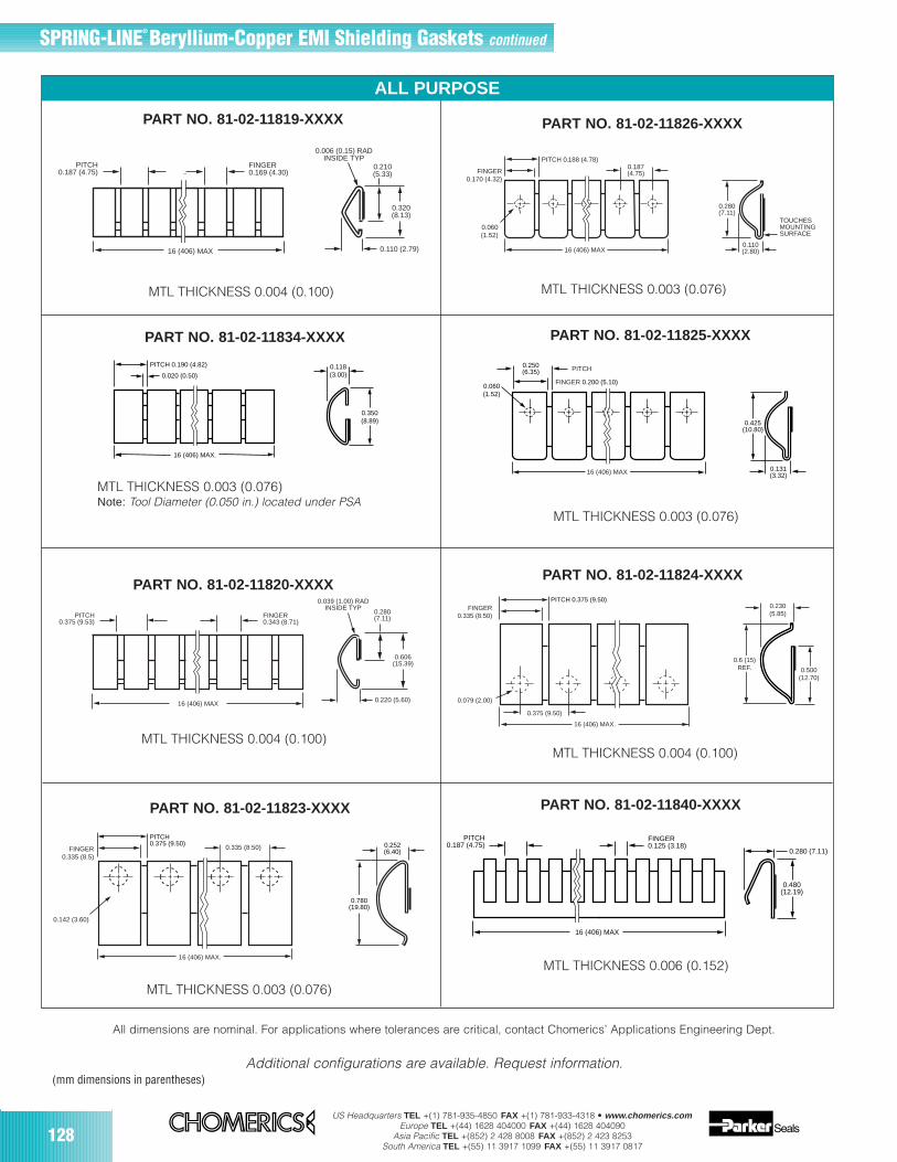
128US Headquarters TEL +(1) 781-935-4850 FAX +(1) 781-933-4318 • www.chomerics.com
Europe TEL +(44) 1628 404000 FAX +(44) 1628 404090Asia Pacific TEL +(852) 2 428 8008 FAX +(852) 2 423 8253
South America TEL +(55) 11 3917 1099 FAX +(55) 11 3917 0817
PART NO. 81-02-11840-XXXX
0.480(12.19)
0.280 (7.11)
PITCH0.187 (4.75)
FINGER0.125 (3.18)
16 (406) MAX
MTL THICKNESS 0.006 (0.152)
16 (406) MAX.
PITCH 0.190 (4.82)
0.020 (0.50)0.118(3.00)
0.350(8.89)
PART NO. 81-02-11834-XXXX
MTL THICKNESS 0.003 (0.076)Note: Tool Diameter (0.050 in.) located under PSA
SPRING-LINE® Beryllium-Copper EMI Shielding Gaskets continued
PART NO. 81-02-11823-XXXX
FINGER0.335 (8.5)
0.142 (3.60)
0.335 (8.50)
16 (406) MAX.
PITCH0.375 (9.50)
0.780(19.80)
0.252(6.40)
MTL THICKNESS 0.003 (0.076)
PART NO. 81-02-11824-XXXX
FINGER0.335 (8.50)
0.230(5.85)
0.375 (9.50)
0.079 (2.00)
0.500(12.70)
0.6 (15)REF.
PITCH 0.375 (9.50)
16 (406) MAX.
MTL THICKNESS 0.004 (0.100)
PART NO. 81-02-11825-XXXX
MTL THICKNESS 0.003 (0.076)
0.250(6.35)
0.060(1.52)
0.131(3.32)
0.425(10.80)
16 (406) MAX
PITCH
FINGER 0.200 (5.10)
PART NO. 81-02-11826-XXXX
MTL THICKNESS 0.003 (0.076)
PITCH 0.188 (4.78)0.187(4.75)FINGER
0.170 (4.32)
0.060 (1.52)
TOUCHESMOUNTINGSURFACE
0.110(2.80)
0.280(7.11)
16 (406) MAX
All dimensions are nominal. For applications where tolerances are critical, contact Chomerics’ Applications Engineering Dept.
PART NO. 81-02-11819-XXXX
MTL THICKNESS 0.004 (0.100)
FINGER0.169 (4.30)
PITCH0.187 (4.75)
0.320(8.13)
0.210(5.33)
0.006 (0.15) RADINSIDE TYP
0.110 (2.79)16 (406) MAX
PART NO. 81-02-11820-XXXX
MTL THICKNESS 0.004 (0.100)
FINGER0.343 (8.71)
PITCH0.375 (9.53)
16 (406) MAX
0.606(15.39)
0.280(7.11)
0.039 (1.00) RADINSIDE TYP
0.220 (5.60)
ALL PURPOSE
Additional configurations are available. Request information.(mm dimensions in parentheses)
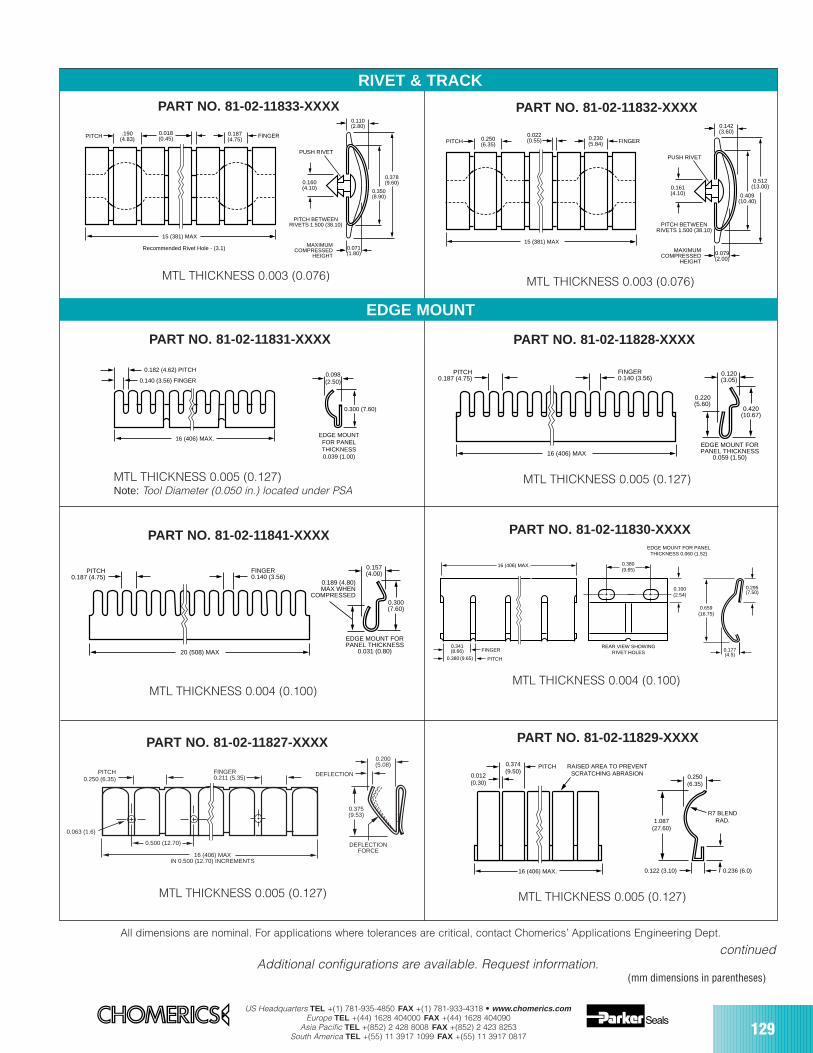
US Headquarters TEL +(1) 781-935-4850 FAX +(1) 781-933-4318 • www.chomerics.comEurope TEL +(44) 1628 404000 FAX +(44) 1628 404090
Asia Pacific TEL +(852) 2 428 8008 FAX +(852) 2 423 8253South America TEL +(55) 11 3917 1099 FAX +(55) 11 3917 0817 129
PART NO. 81-02-11832-XXXX
MTL THICKNESS 0.003 (0.076)
0.512(13.00)
0.409(10.40)
MAXIMUMCOMPRESSED
HEIGHT
PUSH RIVET
0.079(2.00)
0.142(3.60)
PITCH BETWEENRIVETS 1.500 (38.10)
0.250(6.35)
0.230(5.84)
0.022(0.55)PITCH
15 (381) MAX
FINGER
0.161(4.10)
PART NO. 81-02-11833-XXXX
MTL THICKNESS 0.003 (0.076)
0.378(9.60)
0.350(8.90)
MAXIMUMCOMPRESSED
HEIGHT
0.071(1.80)
0.110(2.80)
PITCH BETWEENRIVETS 1.500 (38.10)
.190(4.83)
0.018(0.45)PITCH
15 (381) MAX
FINGER0.187(4.75)
PUSH RIVET
0.160(4.10)
Recommended Rivet Hole - (3.1)
PART NO. 81-02-11829-XXXX
MTL THICKNESS 0.005 (0.127)
0.012(0.30)
0.374(9.50)
RAISED AREA TO PREVENTSCRATCHING ABRASION
16 (406) MAX.
1.087(27.60)
0.250(6.35)
R7 BLENDRAD.
0.122 (3.10) 0.236 (6.0)
PITCH
PART NO. 81-02-11830-XXXX
MTL THICKNESS 0.004 (0.100)
16 (406) MAX.
0.341(8.66)
0.380(9.65)
FINGER
PITCH0.380 (9.65)
0.100(2.54)
REAR VIEW SHOWINGRIVET HOLES
EDGE MOUNT FOR PANELTHICKNESS 0.060 (1.52)
0.659(16.75)
0.295(7.50)
0.177(4.5)
All dimensions are nominal. For applications where tolerances are critical, contact Chomerics’ Applications Engineering Dept.
continued
PART NO. 81-02-11827-XXXX
0.375(9.53)
DEFLECTIONFORCE
0.200(5.08)
PITCH 0.250 (6.35)
16 (406) MAXIN 0.500 (12.70) INCREMENTS
DEFLECTION
0.063 (1.6)
0.500 (12.70)
FINGER0.211 (5.35)
MTL THICKNESS 0.005 (0.127)
RIVET & TRACK
PART NO. 81-02-11831-XXXX
0.140 (3.56) FINGER
0.182 (4.62) PITCH
16 (406) MAX.
0.098(2.50)
0.300 (7.60)
EDGE MOUNTFOR PANELTHICKNESS0.039 (1.00)
MTL THICKNESS 0.005 (0.127)Note: Tool Diameter (0.050 in.) located under PSA
PART NO. 81-02-11828-XXXX
MTL THICKNESS 0.005 (0.127)
PITCH0.187 (4.75)
FINGER0.140 (3.56)
16 (406) MAX
0.420(10.67)
0.120(3.05)
0.220(5.60)
EDGE MOUNT FORPANEL THICKNESS
0.059 (1.50)
PART NO. 81-02-11841-XXXX
MTL THICKNESS 0.004 (0.100)
PITCH0.187 (4.75)
FINGER0.140 (3.56)
20 (508) MAX
0.300(7.60)
0.157(4.00)
0.189 (4.80)MAX WHEN
COMPRESSED
EDGE MOUNT FORPANEL THICKNESS
0.031 (0.80)
EDGE MOUNT
Additional configurations are available. Request information.(mm dimensions in parentheses)
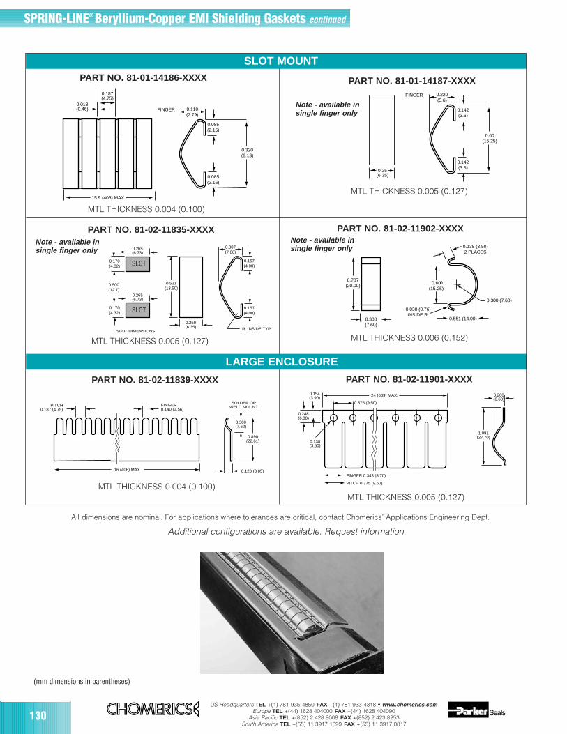
130US Headquarters TEL +(1) 781-935-4850 FAX +(1) 781-933-4318 • www.chomerics.com
Europe TEL +(44) 1628 404000 FAX +(44) 1628 404090Asia Pacific TEL +(852) 2 428 8008 FAX +(852) 2 423 8253
South America TEL +(55) 11 3917 1099 FAX +(55) 11 3917 0817
SLOT MOUNT
SPRING-LINE® Beryllium-Copper EMI Shielding Gaskets continued
PART NO. 81-02-11902-XXXX
0.551 (14.00)
0.138 (3.50)2 PLACES
0.60(15.25)
0.030 (0.76)INSIDE R.
0.300 (7.60)
0.787(20.00)
0.300(7.60)
0
MTL THICKNESS 0.006 (0.152)
Note - available in single finger only
All dimensions are nominal. For applications where tolerances are critical, contact Chomerics’ Applications Engineering Dept.
0.307(7.80)
0.157(4.00)
0.531(13.50)
R. INSIDE TYP.SLOT DIMENSIONS
0.250(6.35)
0.500(12.7)
0.170(4.32)
0.170(4.32)
0.265(6.73)
0.265(6.73)
0.157(4.00)
PART NO. 81-02-11835-XXXX
MTL THICKNESS 0.005 (0.127)
Note - available insingle finger only
PART NO. 81-02-11901-XXXX
MTL THICKNESS 0.005 (0.127)
0.248(6.30)
0.154(3.90)
0.138(3.50)
0.260(6.60)
1.091(27.70)
24 (609) MAX.
FINGER 0.343 (8.70)
PITCH 0.375 (9.50)
0.375 (9.50)PITCH
0.187 (4.75)FINGER0.140 (3.56)
0.890(22.61)
0.300(7.62)
SOLDER ORWELD MOUNT
0.120 (3.05)16 (406) MAX
PART NO. 81-02-11839-XXXX
MTL THICKNESS 0.004 (0.100)
Additional configurations are available. Request information.
0.110(2.79)
0.085(2.16)
0.085(2.16)
0.320(8.13)
0.187(4.75)
0.018(0.46)
15.9 (406) MAX
FINGER
PART NO. 81-01-14186-XXXX
MTL THICKNESS 0.004 (0.100)
0.220(5.6)
0.142(3.6)
0.142(3.6)
0.60(15.25)
FINGER
0.25(6.35)
MTL THICKNESS 0.005 (0.127)
PART NO. 81-01-14187-XXXX
LARGE ENCLOSURE
Note - available in single finger only
(mm dimensions in parentheses)
SLOT
SLOT

No. of slots 01 02 03 04 05 06 07 08 09 10in cage (XX)
Length “L” 0.990 1.790 2.590 3.390 4.190 4.990 5.790 6.590 7.390 8.190inches (mm) (25.15) (45.47) (65.78) (86.11) (106.43) (126.75) (147.02) (167.39) (187.71) (208.03)
US Headquarters TEL +(1) 781-935-4850 FAX +(1) 781-933-4318 • www.chomerics.comEurope TEL +(44) 1628 404000 FAX +(44) 1628 404090
Asia Pacific TEL +(852) 2 428 8008 FAX +(852) 2 423 8253South America TEL +(55) 11 3917 1099 FAX +(55) 11 3917 0817
131
Base Material Specifications
Material Alloy SS 301/302
Temper 1/2 Hard
Finish Bright
Yield Strength 130-150 ksi
Tensile Strength 150 ksi(Per ASTM A666)
Plating Options
Tin (pre or post)
Plating Thickness - 5.08-10.16 microns(Per MIL-T-10727)
SPRING-LINE® Stainless Steel Card Cage Gaskets
SPRING-LINEStainless Steel Card Cage Gaskets SPRING-LINE stainless steel card cage gaskets are designed to provide EMI shielding to the expansion slot area of PC andServer chassis. Chomerics’ standard card cage series is avail-able for PCI/EISA slot configurations from 1 to 10. The gasketscan also be modified to include additional slots and variablepitch designs.
Designed for cost effectiveness and ease of installation,Chomerics’ card cage gaskets fit into most existing chassis with-out modifications. The contact fingers are designed to minimizeany snagging during the installation of cards.
SPRING-LINE card cage gaskets are available in both stan-dard and custom configurations, including tin-plating, to helpmeet demanding shielding requirements.
Table 1
Ordering ProcedureUse the following part number system toorder SPRING-LINE card cage gaskets.
81 - XX - XX X XX - XXX X Plating finish2 = Clean and bright (unplated)5 = Tin
SPRING-LINEProduct
01= no PSA (standard)02= with PSA
003 Standard Base Material Thickness, 0.003 inch (0.076 mm)
Material AlloyA= SS 301/302
No. of FingersSurrounding Slot(Standard = 20)
Figure 1 Standard SPRING-LINE Card Cage Gasket Configuration
P/N Example: 81-01-05A20-0032 Denotes a five-slot, 0.003 inch (0.076 mm) thick,stainless steel (301/302) card cage gasket with no PSA, twenty fingers and no finish.
(mm dimensions in parentheses)
METAL EMI GASKETS
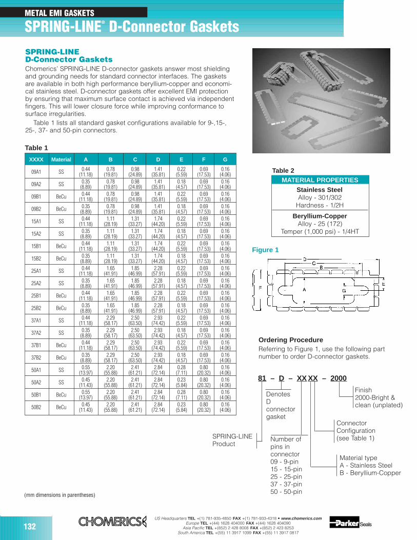
132US Headquarters TEL +(1) 781-935-4850 FAX +(1) 781-933-4318 • www.chomerics.com
Europe TEL +(44) 1628 404000 FAX +(44) 1628 404090Asia Pacific TEL +(852) 2 428 8008 FAX +(852) 2 423 8253
South America TEL +(55) 11 3917 1099 FAX +(55) 11 3917 0817
METAL EMI GASKETS
SPRING-LINE® D-Connector GasketsSPRING-LINED-Connector Gaskets Chomerics’ SPRING-LINE D-connector gaskets answer most shieldingand grounding needs for standard connector interfaces. The gasketsare available in both high performance beryllium-copper and economi-cal stainless steel. D-connector gaskets offer excellent EMI protectionby ensuring that maximum surface contact is achieved via independentfingers. This will lower closure force while improving conformance tosurface irregularities.
Table 1 lists all standard gasket configurations available for 9-,15-,25-, 37- and 50-pin connectors.
Table 1
XXXX Material A B C D E F G
09A1 SS 0.44 0.78 0.98 1.41 0.22 0.69 0.16(11.18) (19.81) (24.89) (35.81) (5.59) (17.53) (4.06)
09A2 SS 0.35 0.78 0.98 1.41 0.18 0.69 0.16(8.89) (19.81) (24.89) (35.81) (4.57) (17.53) (4.06)
09B1 BeCu 0.44 0.78 0.98 1.41 0.22 0.69 0.16(11.18) (19.81) (24.89) (35.81) (5.59) (17.53) (4.06)
09B2 BeCu 0.35 0.78 0.98 1.41 0.18 0.69 0.16(8.89) (19.81) (24.89) (35.81) (4.57) (17.53) (4.06)
15A1 SS 0.44 1.11 1.31 1.74 0.22 0.69 0.16(11.18) (28.19) (33.27) (44.20) (5.59) (17.53) (4.06)
15A2 SS 0.35 1.11 1.31 1.74 0.18 0.69 0.16(8.89) (28.19) (33.27) (44.20) (4.57) (17.53) (4.06)
15B1 BeCu 0.44 1.11 1.31 1.74 0.22 0.69 0.16(11.18) (28.19) (33.27) (44.20) (5.59) (17.53) (4.06)
15B2 BeCu 0.35 1.11 1.31 1.74 0.18 0.69 0.16(8.89) (28.19) (33.27) (44.20) (4.57) (17.53) (4.06)
25A1 SS 0.44 1.65 1.85 2.28 0.22 0.69 0.16(11.18) (41.91) (46.99) (57.91) (5.59) (17.53) (4.06)
25A2 SS 0.35 1.65 1.85 2.28 0.18 0.69 0.16(8.89) (41.91) (46.99) (57.91) (4.57) (17.53) (4.06)
25B1 BeCu 0.44 1.65 1.85 2.28 0.22 0.69 0.16(11.18) (41.91) (46.99) (57.91) (5.59) (17.53) (4.06)
25B2 BeCu 0.35 1.65 1.85 2.28 0.18 0.69 0.16(8.89) (41.91) (46.99) (57.91) (4.57) (17.53) (4.06)
37A1 SS 0.44 2.29 2.50 2.93 0.22 0.69 0.16(11.18) (58.17) (63.50) (74.42) (5.59) (17.53) (4.06)
37A2 SS 0.35 2.29 2.50 2.93 0.18 0.69 0.16(8.89) (58.17) (63.50) (74.42) (4.57) (17.53) (4.06)
37B1 BeCu 0.44 2.29 2.50 2.93 0.22 0.69 0.16(11.18) (58.17) (63.50) (74.42) (5.59) (17.53) (4.06)
37B2 BeCu 0.35 2.29 2.50 2.93 0.18 0.69 0.16(8.89) (58.17) (63.50) (74.42) (4.57) (17.53) (4.06)
50A1 SS 0.55 2.20 2.41 2.84 0.28 0.80 0.16(13.97) (55.88) (61.21) (72.14) (7.11) (20.32) (4.06)
50A2 SS 0.45 2.20 2.41 2.84 0.23 0.80 0.16(11.43) (55.88) (61.21) (72.14) (5.84) (20.32) (4.06)
50B1 BeCu 0.55 2.20 2.41 2.84 0.28 0.80 0.16(13.97) (55.88) (61.21) (72.14) (7.11) (20.32) (4.06)
50B2 BeCu 0.45 2.20 2.41 2.84 0.23 0.80 0.16(11.43) (55.88) (61.21) (72.14) (5.84) (20.32) (4.06)
MATERIAL PROPERTIES
Stainless SteelAlloy - 301/302
Hardness - 1/2H
Beryllium-CopperAlloy - 25 (172)
Temper (1,000 psi) - 1/4HT
Table 2
Ordering ProcedureReferring to Figure 1, use the following partnumber to order D-connector gaskets.
Figure 1
81 – D – XX XX – 2000
SPRING-LINEProduct
Finish 2000-Bright &clean (unplated)
Material typeA - Stainless SteelB - Beryllium-Copper
ConnectorConfiguration(see Table 1)
DenotesDconnectorgasket
Number ofpins in connector09 - 9-pin15 - 15-pin25 - 25-pin37 - 37-pin50 - 50-pin(mm dimensions in parentheses)
133
ConductiveCompounds
SECTION CONTENTS PAGE
CHO-BOND® conductive adhesives 135
CHO-BOND® conductive sealants and caulks 138
CHO-SHIELD® conductive coatings 140
CHO-FLEX® conductive coatings and inks 142
AdhesivesSealants and CaulksCoatingsInks
US Headquarters TEL +(1) 781-935-4850 FAX +(1) 781-933-4318 • www.chomerics.comEurope TEL +(44) 1628 404000 FAX +(44) 1628 404090
Asia Pacific TEL +(852) 2 428 8008 FAX +(852) 2 423 8253South America TEL +(55) 11 3917 1099 FAX +(55) 11 3917 0817
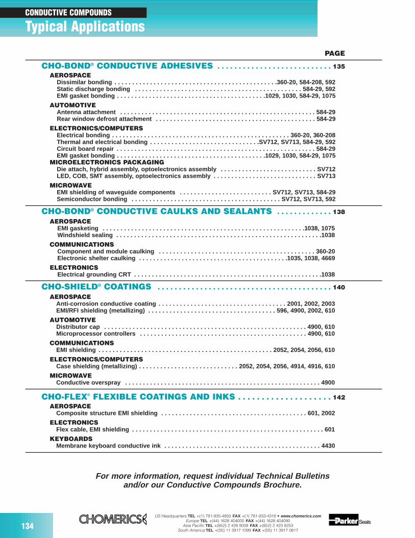
US Headquarters TEL +(1) 781-935-4850 FAX +(1) 781-933-4318 • www.chomerics.comEurope TEL +(44) 1628 404000 FAX +(44) 1628 404090
Asia Pacific TEL +(852) 2 428 8008 FAX +(852) 2 423 8253South America TEL +(55) 11 3917 1099 FAX +(55) 11 3917 0817
134
PAGE
CHO-BOND® CONDUCTIVE ADHESIVES . . . . . . . . . . . . . . . . . . . . . . . . . . . 135AEROSPACE
Dissimilar bonding . . . . . . . . . . . . . . . . . . . . . . . . . . . . . . . . . . . . . . . . . . . . . .360-20, 584-208, 592Static discharge bonding . . . . . . . . . . . . . . . . . . . . . . . . . . . . . . . . . . . . . . . . . . . . . . . 584-29, 592EMI gasket bonding . . . . . . . . . . . . . . . . . . . . . . . . . . . . . . . . . . . . . . . . . .1029, 1030, 584-29, 1075
AUTOMOTIVEAntenna attachment . . . . . . . . . . . . . . . . . . . . . . . . . . . . . . . . . . . . . . . . . . . . . . . . . . . . . . . 584-29Rear window defrost attachment . . . . . . . . . . . . . . . . . . . . . . . . . . . . . . . . . . . . . . . . . . . . . 584-29
ELECTRONICS/COMPUTERSElectrical bonding . . . . . . . . . . . . . . . . . . . . . . . . . . . . . . . . . . . . . . . . . . . . . . . . . . 360-20, 360-208Thermal and electrical bonding . . . . . . . . . . . . . . . . . . . . . . . . . . . . . . .SV712, SV713, 584-29, 592Circuit board repair . . . . . . . . . . . . . . . . . . . . . . . . . . . . . . . . . . . . . . . . . . . . . . . . . . . . . . . . 584-29EMI gasket bonding . . . . . . . . . . . . . . . . . . . . . . . . . . . . . . . . . . . . . . . . . .1029, 1030, 584-29, 1075
MICROELECTRONICS PACKAGINGDie attach, hybrid assembly, optoelectronics assembly . . . . . . . . . . . . . . . . . . . . . . . . . . . SV712LED, COB, SMT assembly, optoelectronics assembly . . . . . . . . . . . . . . . . . . . . . . . . . . . . . SV713
MICROWAVEEMI shielding of waveguide components . . . . . . . . . . . . . . . . . . . . . . . . . . SV712, SV713, 584-29Semiconductor bonding . . . . . . . . . . . . . . . . . . . . . . . . . . . . . . . . . . . . . . . . . . SV712, SV713, 592
CHO-BOND® CONDUCTIVE CAULKS AND SEALANTS . . . . . . . . . . . . . 138AEROSPACE
EMI gasketing . . . . . . . . . . . . . . . . . . . . . . . . . . . . . . . . . . . . . . . . . . . . . . . . . . . . . . . . .1038, 1075Windshield sealing . . . . . . . . . . . . . . . . . . . . . . . . . . . . . . . . . . . . . . . . . . . . . . . . . . . . . . . . . .1038
COMMUNICATIONSComponent and module caulking . . . . . . . . . . . . . . . . . . . . . . . . . . . . . . . . . . . . . . . . . . . . 360-20Electronic shelter caulking . . . . . . . . . . . . . . . . . . . . . . . . . . . . . . . . . . . . . . . . . .1035, 1038, 4669
ELECTRONICSElectrical grounding CRT . . . . . . . . . . . . . . . . . . . . . . . . . . . . . . . . . . . . . . . . . . . . . . . . . . . . .1038
CHO-SHIELD® COATINGS . . . . . . . . . . . . . . . . . . . . . . . . . . . . . . . . . . . . . . . . . 140AEROSPACE
Anti-corrosion conductive coating . . . . . . . . . . . . . . . . . . . . . . . . . . . . . . . . . . . . 2001, 2002, 2003EMI/RFI shielding (metallizing) . . . . . . . . . . . . . . . . . . . . . . . . . . . . . . . . . . . . 596, 4900, 2002, 610
AUTOMOTIVEDistributor cap . . . . . . . . . . . . . . . . . . . . . . . . . . . . . . . . . . . . . . . . . . . . . . . . . . . . . . . . . 4900, 610Microprocessor controllers . . . . . . . . . . . . . . . . . . . . . . . . . . . . . . . . . . . . . . . . . . . . . . . 4900, 610
COMMUNICATIONSEMI shielding . . . . . . . . . . . . . . . . . . . . . . . . . . . . . . . . . . . . . . . . . . . . . . . . . 2052, 2054, 2056, 610
ELECTRONICS/COMPUTERSCase shielding (metallizing) . . . . . . . . . . . . . . . . . . . . . . . . . . . . 2052, 2054, 2056, 4914, 4916, 610
MICROWAVEConductive overspray . . . . . . . . . . . . . . . . . . . . . . . . . . . . . . . . . . . . . . . . . . . . . . . . . . . . . . . 4900
CHO-FLEX® FLEXIBLE COATINGS AND INKS . . . . . . . . . . . . . . . . . . . . 142AEROSPACE
Composite structure EMI shielding . . . . . . . . . . . . . . . . . . . . . . . . . . . . . . . . . . . . . . . . . 601, 2002
ELECTRONICSFlex cable, EMI shielding . . . . . . . . . . . . . . . . . . . . . . . . . . . . . . . . . . . . . . . . . . . . . . . . . . . . . . 601
KEYBOARDSMembrane keyboard conductive ink . . . . . . . . . . . . . . . . . . . . . . . . . . . . . . . . . . . . . . . . . . . . 4430
For more information, request individual Technical Bulletins and/or our Conductive Compounds Brochure.
CONDUCTIVE COMPOUNDS
Typical Applications
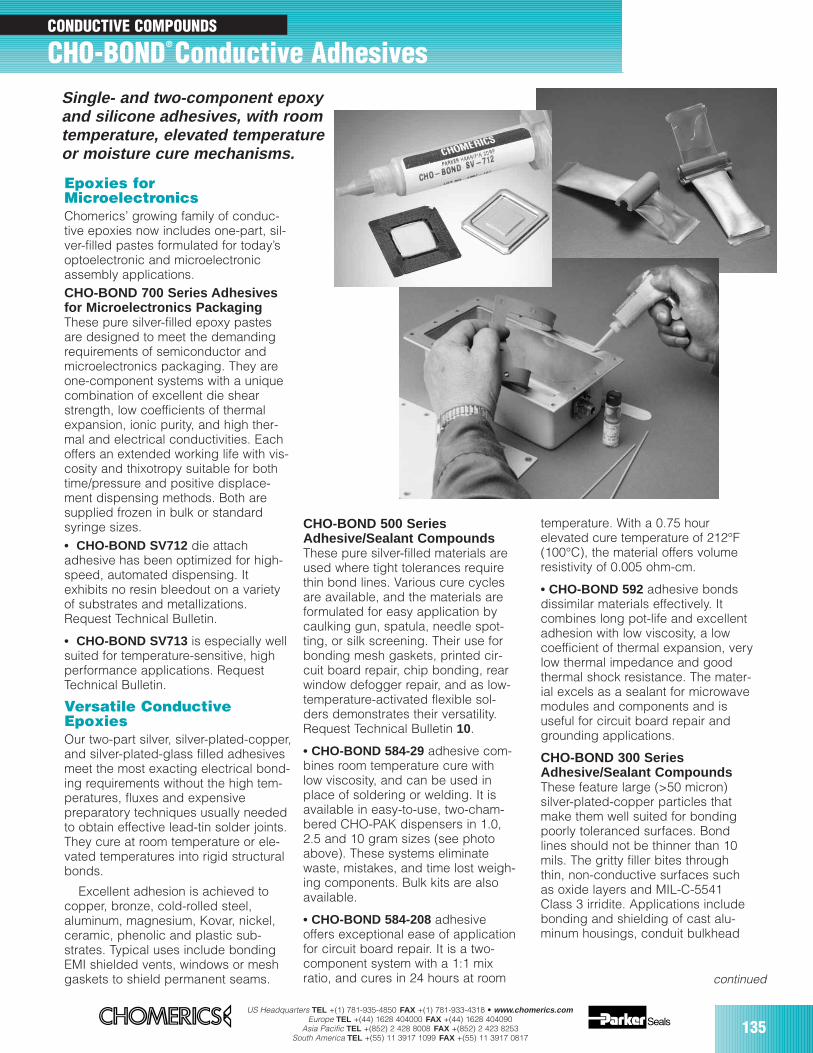
US Headquarters TEL +(1) 781-935-4850 FAX +(1) 781-933-4318 • www.chomerics.comEurope TEL +(44) 1628 404000 FAX +(44) 1628 404090
Asia Pacific TEL +(852) 2 428 8008 FAX +(852) 2 423 8253South America TEL +(55) 11 3917 1099 FAX +(55) 11 3917 0817
135
CONDUCTIVE COMPOUNDS
CHO-BOND® Conductive Adhesives
Epoxies forMicroelectronicsChomerics’ growing family of conduc-tive epoxies now includes one-part, sil-ver-filled pastes formulated for today’soptoelectronic and microelectronicassembly applications.CHO-BOND 700 Series Adhesivesfor Microelectronics PackagingThese pure silver-filled epoxy pastesare designed to meet the demandingrequirements of semiconductor andmicroelectronics packaging. They areone-component systems with a uniquecombination of excellent die shearstrength, low coefficients of thermalexpansion, ionic purity, and high ther-mal and electrical conductivities. Eachoffers an extended working life with vis-cosity and thixotropy suitable for bothtime/pressure and positive displace-ment dispensing methods. Both aresupplied frozen in bulk or standardsyringe sizes.• CHO-BOND SV712 die attach adhesive has been optimized for high-speed, automated dispensing. Itexhibits no resin bleedout on a varietyof substrates and metallizations.Request Technical Bulletin.
• CHO-BOND SV713 is especially wellsuited for temperature-sensitive, highperformance applications. RequestTechnical Bulletin.
Versatile ConductiveEpoxiesOur two-part silver, silver-plated-copper,and silver-plated-glass filled adhesivesmeet the most exacting electrical bond-ing requirements without the high tem-peratures, fluxes and expensivepreparatory techniques usually neededto obtain effective lead-tin solder joints.They cure at room temperature or ele-vated temperatures into rigid structuralbonds.
Excellent adhesion is achieved tocopper, bronze, cold-rolled steel, aluminum, magnesium, Kovar, nickel,ceramic, phenolic and plastic sub-strates. Typical uses include bondingEMI shielded vents, windows or meshgaskets to shield permanent seams.
CHO-BOND 500 SeriesAdhesive/Sealant CompoundsThese pure silver-filled materials areused where tight tolerances requirethin bond lines. Various cure cyclesare available, and the materials areformulated for easy application bycaulking gun, spatula, needle spot-ting, or silk screening. Their use forbonding mesh gaskets, printed cir-cuit board repair, chip bonding, rearwindow defogger repair, and as low-temperature-activated flexible sol-ders demonstrates their versatility.Request Technical Bulletin 10.
• CHO-BOND 584-29 adhesive com-bines room temperature cure withlow viscosity, and can be used inplace of soldering or welding. It isavailable in easy-to-use, two-cham-bered CHO-PAK dispensers in 1.0,2.5 and 10 gram sizes (see photoabove). These systems eliminatewaste, mistakes, and time lost weigh-ing components. Bulk kits are alsoavailable.
• CHO-BOND 584-208 adhesiveoffers exceptional ease of applicationfor circuit board repair. It is a two-component system with a 1:1 mixratio, and cures in 24 hours at room
temperature. With a 0.75 hourelevated cure temperature of 212°F(100°C), the material offers volumeresistivity of 0.005 ohm-cm.
• CHO-BOND 592 adhesive bondsdissimilar materials effectively. Itcombines long pot-life and excellentadhesion with low viscosity, a lowcoefficient of thermal expansion, verylow thermal impedance and goodthermal shock resistance. The mater-ial excels as a sealant for microwavemodules and components and isuseful for circuit board repair andgrounding applications.
CHO-BOND 300 SeriesAdhesive/Sealant CompoundsThese feature large (>50 micron) silver-plated-copper particles thatmake them well suited for bondingpoorly toleranced surfaces. Bondlines should not be thinner than 10mils. The gritty filler bites throughthin, non-conductive surfaces suchas oxide layers and MIL-C-5541Class 3 irridite. Applications includebonding and shielding of cast alu-minum housings, conduit bulkhead
Single- and two-component epoxyand silicone adhesives, with roomtemperature, elevated temperature or moisture cure mechanisms.
continued
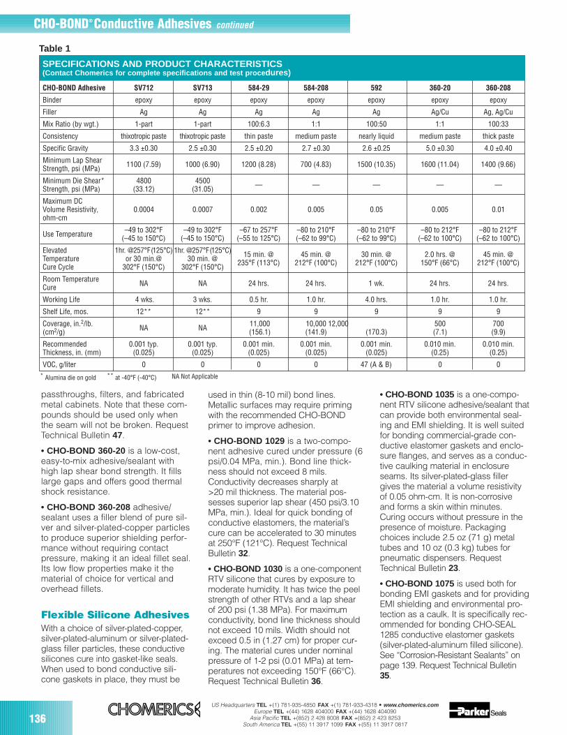
US Headquarters TEL +(1) 781-935-4850 FAX +(1) 781-933-4318 • www.chomerics.comEurope TEL +(44) 1628 404000 FAX +(44) 1628 404090
Asia Pacific TEL +(852) 2 428 8008 FAX +(852) 2 423 8253South America TEL +(55) 11 3917 1099 FAX +(55) 11 3917 0817
136
CHO-BOND Adhesive SV712 SV713 584-29 584-208 592 360-20 360-208
Binder epoxy epoxy epoxy epoxy epoxy epoxy epoxy
Filler Ag Ag Ag Ag Ag Ag/Cu Ag, Ag/Cu
Mix Ratio (by wgt.) 1-part 1-part 100:6.3 1:1 100:50 1:1 100:33
Consistency thixotropic paste thixotropic paste thin paste medium paste nearly liquid medium paste thick paste
Specific Gravity 3.3 ±0.30 2.5 ±0.30 2.5 ±0.20 2.7 ±0.30 2.6 ±0.25 5.0 ±0.30 4.0 ±0.40
Minimum Lap ShearStrength, psi (MPa) 1100 (7.59) 1000 (6.90) 1200 (8.28) 700 (4.83) 1500 (10.35) 1600 (11.04) 1400 (9.66)
Minimum Die Shear* 4800 4500Strength, psi (MPa) (33.12) (31.05) — — — — —
Maximum DCVolume Resistivity, 0.0004 0.0007 0.002 0.005 0.05 0.005 0.01ohm-cm
Use Temperature –49 to 302°F –49 to 302°F –67 to 257°F –80 to 210°F –80 to 210°F –80 to 212°F –80 to 212°F(–45 to 150°C) (–45 to 150°C) (–55 to 125°C) (–62 to 99°C) (–62 to 99°C) (–62 to 100°C) (–62 to 100°C)
Elevated 1hr. @257°F(125°C) 1hr. @257°F(125°C)Temperature or 30 min.@ 30 min. @ 15 min. @ 45 min. @ 30 min. @ 2.0 hrs. @ 45 min. @
Cure Cycle 302°F (150°C) 302°F (150°C) 235°F (113°C) 212°F (100°C) 212°F (100°C) 150°F (66°C) 212°F (100°C)
Room Temperature NA NA 24 hrs. 24 hrs. 1 wk. 24 hrs. 24 hrs.Cure
Working Life 4 wks. 3 wks. 0.5 hr. 1.0 hr. 4.0 hrs. 1.0 hr. 1.0 hr.
Shelf Life, mos. 12** 12** 9 9 9 9 9
Coverage, in.2/lb. NA NA 11,000 10,000 12,000 500 700 (cm2/g) (156.1) (141.9) (170.3) (7.1) (9.9)
Recommended 0.001 typ. 0.001 typ. 0.001 min. 0.001 min. 0.001 min. 0.010 min. 0.010 min.Thickness, in. (mm) (0.025) (0.025) (0.025) (0.025) (0.025) (0.25) (0.25)
VOC, g/liter 0 0 0 0 47 (A & B) 0 0
SPECIFICATIONS AND PRODUCT CHARACTERISTICS(Contact Chomerics for complete specifications and test proce dures)
Flexible Silicone AdhesivesWith a choice of silver-plated-copper,silver-plated-aluminum or silver-plated-glass filler particles, these conductivesilicones cure into gasket-like seals.When used to bond conductive sili-cone gaskets in place, they must be
used in thin (8-10 mil) bond lines.Metallic surfaces may require primingwith the recommended CHO-BONDprimer to improve adhesion.
• CHO-BOND 1029 is a two-compo-nent adhesive cured under pressure (6psi/0.04 MPa, min.). Bond line thick-ness should not exceed 8 mils.Conductivity decreases sharply at >20 mil thickness. The material pos-sesses superior lap shear (450 psi/3.10MPa, min.). Ideal for quick bonding ofconductive elastomers, the material’scure can be accelerated to 30 minutesat 250°F (121°C). Request TechnicalBulletin 32.
• CHO-BOND 1030 is a one-componentRTV silicone that cures by exposure tomoderate humidity. It has twice the peelstrength of other RTVs and a lap shearof 200 psi (1.38 MPa). For maximumconductivity, bond line thickness shouldnot exceed 10 mils. Width should notexceed 0.5 in (1.27 cm) for proper cur-ing. The material cures under nominalpressure of 1-2 psi (0.01 MPa) at tem-peratures not exceeding 150°F (66°C).Request Technical Bulletin 36.
CHO-BOND® Conductive Adhesives continued
Table 1
** at -40°F (-40°C)* Alumina die on gold
• CHO-BOND 1035 is a one-compo-nent RTV silicone adhesive/sealant thatcan provide both environmental seal-ing and EMI shielding. It is well suitedfor bonding commercial-grade con-ductive elastomer gaskets and enclo-sure flanges, and serves as a conduc-tive caulking material in enclosureseams. Its silver-plated-glass fillergives the material a volume resistivityof 0.05 ohm-cm. It is non-corrosiveand forms a skin within minutes.Curing occurs without pressure in thepresence of moisture. Packagingchoices include 2.5 oz (71 g) metaltubes and 10 oz (0.3 kg) tubes forpneumatic dispensers. RequestTechnical Bulletin 23.
• CHO-BOND 1075 is used both forbonding EMI gaskets and for providingEMI shielding and environmental pro-tection as a caulk. It is specifically rec-ommended for bonding CHO-SEAL1285 conductive elastomer gaskets (silver-plated-aluminum filled silicone).See “Corrosion-Resistant Sealants” onpage 139. Request Technical Bulletin35.
passthroughs, filters, and fabricatedmetal cabinets. Note that these com-pounds should be used only whenthe seam will not be broken. RequestTechnical Bulletin 47.
• CHO-BOND 360-20 is a low-cost,easy-to-mix adhesive/sealant withhigh lap shear bond strength. It fillslarge gaps and offers good thermalshock resistance.
• CHO-BOND 360-208 adhesive/sealant uses a filler blend of pure sil-ver and silver-plated-copper particlesto produce superior shielding perfor-mance without requiring contactpressure, making it an ideal fillet seal.Its low flow properties make it thematerial of choice for vertical andoverhead fillets.
NA Not Applicable
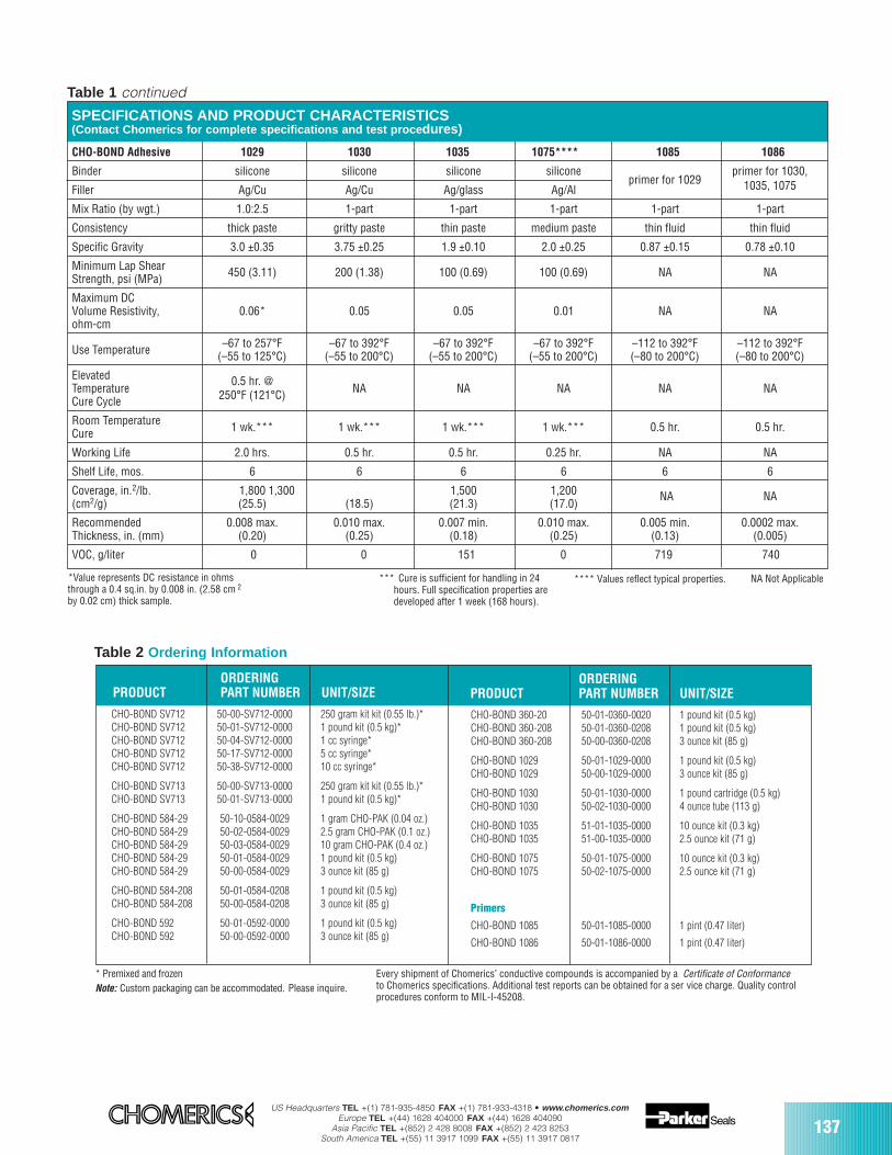
US Headquarters TEL +(1) 781-935-4850 FAX +(1) 781-933-4318 • www.chomerics.comEurope TEL +(44) 1628 404000 FAX +(44) 1628 404090
Asia Pacific TEL +(852) 2 428 8008 FAX +(852) 2 423 8253South America TEL +(55) 11 3917 1099 FAX +(55) 11 3917 0817
137
SPECIFICATIONS AND PRODUCT CHARACTERISTICS(Contact Chomerics for complete specifications and test proce dures)
*Value represents DC resistance in ohmsthrough a 0.4 sq.in. by 0.008 in. (2.58 cm 2
by 0.02 cm) thick sample.
CHO-BOND Adhesive 1029 1030 1035 1075**** 1085 1086
Binder silicone silicone silicone siliconeprimer for 1029
primer for 1030,
Filler Ag/Cu Ag/Cu Ag/glass Ag/Al 1035, 1075
Mix Ratio (by wgt.) 1.0:2.5 1-part 1-part 1-part 1-part 1-part
Consistency thick paste gritty paste thin paste medium paste thin fluid thin fluid
Specific Gravity 3.0 ±0.35 3.75 ±0.25 1.9 ±0.10 2.0 ±0.25 0.87 ±0.15 0.78 ±0.10
Minimum Lap ShearStrength, psi (MPa) 450 (3.11) 200 (1.38) 100 (0.69) 100 (0.69) NA NA
Maximum DCVolume Resistivity, 0.06* 0.05 0.05 0.01 NA NAohm-cm
Use Temperature –67 to 257°F –67 to 392°F –67 to 392°F –67 to 392°F –112 to 392°F –112 to 392°F(–55 to 125°C) (–55 to 200°C) (–55 to 200°C) (–55 to 200°C) (–80 to 200°C) (–80 to 200°C)
Elevated 0.5 hr. @Temperature 250°F (121°C) NA NA NA NA NACure Cycle
Room Temperature 1 wk.*** 1 wk.*** 1 wk.*** 1 wk.*** 0.5 hr. 0.5 hr.Cure
Working Life 2.0 hrs. 0.5 hr. 0.5 hr. 0.25 hr. NA NA
Shelf Life, mos. 6 6 6 6 6 6
Coverage, in.2/lb. 1,800 1,300 1,500 1,200 (cm2/g) (25.5) (18.5) (21.3) (17.0)
NA NA
Recommended 0.008 max. 0.010 max. 0.007 min. 0.010 max. 0.005 min. 0.0002 max.Thickness, in. (mm) (0.20) (0.25) (0.18) (0.25) (0.13) (0.005)
VOC, g/liter 0 0 151 0 719 740
Table 1 continued
CHO-BOND SV712 50-00-SV712-0000 250 gram kit kit (0.55 lb.)*CHO-BOND SV712 50-01-SV712-0000 1 pound kit (0.5 kg)*CHO-BOND SV712 50-04-SV712-0000 1 cc syringe*CHO-BOND SV712 50-17-SV712-0000 5 cc syringe*CHO-BOND SV712 50-38-SV712-0000 10 cc syringe*
CHO-BOND SV713 50-00-SV713-0000 250 gram kit kit (0.55 lb.)*CHO-BOND SV713 50-01-SV713-0000 1 pound kit (0.5 kg)*
CHO-BOND 584-29 50-10-0584-0029 1 gram CHO-PAK (0.04 oz.)CHO-BOND 584-29 50-02-0584-0029 2.5 gram CHO-PAK (0.1 oz.)CHO-BOND 584-29 50-03-0584-0029 10 gram CHO-PAK (0.4 oz.)CHO-BOND 584-29 50-01-0584-0029 1 pound kit (0.5 kg)CHO-BOND 584-29 50-00-0584-0029 3 ounce kit (85 g)
CHO-BOND 584-208 50-01-0584-0208 1 pound kit (0.5 kg)CHO-BOND 584-208 50-00-0584-0208 3 ounce kit (85 g)
CHO-BOND 592 50-01-0592-0000 1 pound kit (0.5 kg)CHO-BOND 592 50-00-0592-0000 3 ounce kit (85 g)
* Premixed and frozenNote: Custom packaging can be accommodated. Please inquire.
ORDERING PRODUCT PART NUMBER UNIT/SIZE
CHO-BOND 360-20 50-01-0360-0020 1 pound kit (0.5 kg)CHO-BOND 360-208 50-01-0360-0208 1 pound kit (0.5 kg)CHO-BOND 360-208 50-00-0360-0208 3 ounce kit (85 g)
CHO-BOND 1029 50-01-1029-0000 1 pound kit (0.5 kg)CHO-BOND 1029 50-00-1029-0000 3 ounce kit (85 g)
CHO-BOND 1030 50-01-1030-0000 1 pound cartridge (0.5 kg)CHO-BOND 1030 50-02-1030-0000 4 ounce tube (113 g)
CHO-BOND 1035 51-01-1035-0000 10 ounce kit (0.3 kg)CHO-BOND 1035 51-00-1035-0000 2.5 ounce kit (71 g)
CHO-BOND 1075 50-01-1075-0000 10 ounce kit (0.3 kg)CHO-BOND 1075 50-02-1075-0000 2.5 ounce kit (71 g)
Primers
CHO-BOND 1085 50-01-1085-0000 1 pint (0.47 liter)
CHO-BOND 1086 50-01-1086-0000 1 pint (0.47 liter)
ORDERING PRODUCT PART NUMBER UNIT/SIZE
Table 2 Ordering Information
**** Values reflect typical properties.*** Cure is sufficient for handling in 24hours. Full specification properties aredeveloped after 1 week (168 hours).
NA Not Applicable
Every shipment of Chomerics’ conductive compounds is accompanied by a Certificate of Conformanceto Chomerics specifications. Additional test reports can be obtained for a ser vice charge. Quality controlprocedures conform to MIL-I-45208.
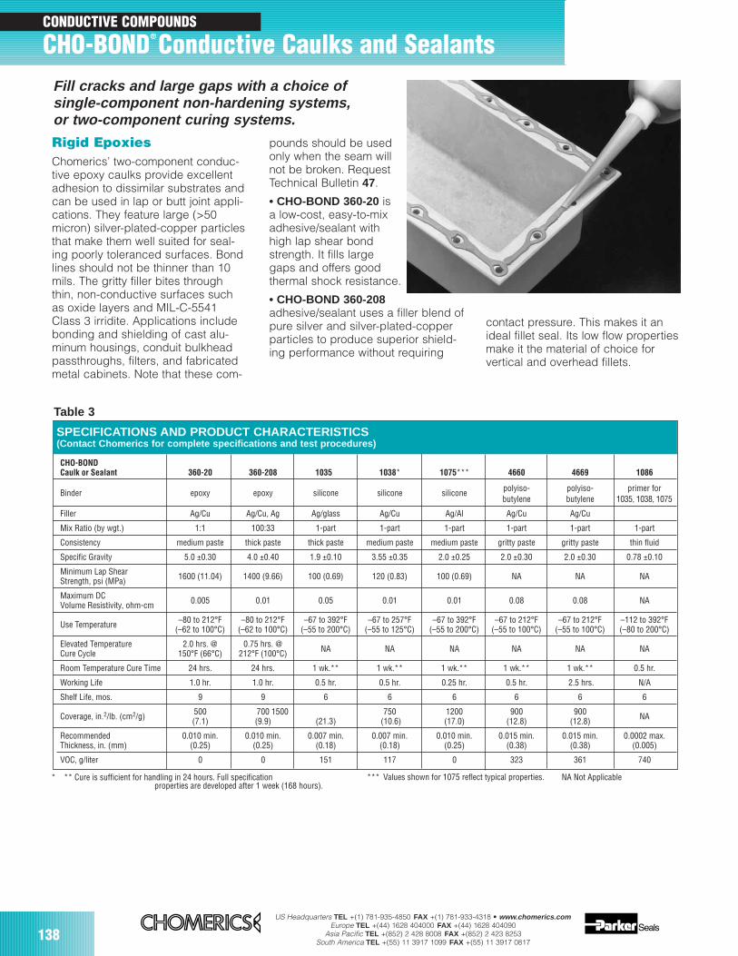
US Headquarters TEL +(1) 781-935-4850 FAX +(1) 781-933-4318 • www.chomerics.comEurope TEL +(44) 1628 404000 FAX +(44) 1628 404090
Asia Pacific TEL +(852) 2 428 8008 FAX +(852) 2 423 8253South America TEL +(55) 11 3917 1099 FAX +(55) 11 3917 0817
138
*** Values shown for 1075 reflect typical properties.
CHO-BONDCaulk or Sealant 360-20 360-208 1035 1038* 1075*** 4660 4669 1086
Binder epoxy epoxy silicone silicone silicone polyiso- polyiso- primer forbutylene butylene 1035, 1038, 1075
Filler Ag/Cu Ag/Cu, Ag Ag/glass Ag/Cu Ag/Al Ag/Cu Ag/Cu
Mix Ratio (by wgt.) 1:1 100:33 1-part 1-part 1-part 1-part 1-part 1-part
Consistency medium paste thick paste thick paste medium paste medium paste gritty paste gritty paste thin fluid
Specific Gravity 5.0 ±0.30 4.0 ±0.40 1.9 ±0.10 3.55 ±0.35 2.0 ±0.25 2.0 ±0.30 2.0 ±0.30 0.78 ±0.10
Minimum Lap ShearStrength, psi (MPa) 1600 (11.04) 1400 (9.66) 100 (0.69) 120 (0.83) 100 (0.69) NA NA NA
Maximum DCVolume Resistivity, ohm-cm 0.005 0.01 0.05 0.01 0.01 0.08 0.08 NA
Use Temperature –80 to 212°F –80 to 212°F –67 to 392°F –67 to 257°F –67 to 392°F –67 to 212°F –67 to 212°F –112 to 392°F(–62 to 100°C) (–62 to 100°C) (–55 to 200°C) (–55 to 125°C) (–55 to 200°C) (–55 to 100°C) (–55 to 100°C) (–80 to 200°C)
Elevated Temperature 2.0 hrs. @ 0.75 hrs. @ NA NA NA NA NA NACure Cycle 150°F (66°C) 212°F (100°C)
Room Temperature Cure Time 24 hrs. 24 hrs. 1 wk.** 1 wk.** 1 wk.** 1 wk.** 1 wk.** 0.5 hr.
Working Life 1.0 hr. 1.0 hr. 0.5 hr. 0.5 hr. 0.25 hr. 0.5 hr. 2.5 hrs. N/A
Shelf Life, mos. 9 9 6 6 6 6 6 6
Coverage, in.2/lb. (cm2/g) 500 700 1500 750 1200 900 900(7.1) (9.9) (21.3) (10.6) (17.0) (12.8) (12.8) NA
Recommended 0.010 min. 0.010 min. 0.007 min. 0.007 min. 0.010 min. 0.015 min. 0.015 min. 0.0002 max.Thickness, in. (mm) (0.25) (0.25) (0.18) (0.18) (0.25) (0.38) (0.38) (0.005)
VOC, g/liter 0 0 151 117 0 323 361 740
SPECIFICATIONS AND PRODUCT CHARACTERISTICS(Contact Chomerics for complete specifications and test procedures)
CONDUCTIVE COMPOUNDS
CHO-BOND® Conductive Caulks and SealantsFill cracks and large gaps with a choice ofsingle-component non-hardening systems,or two-component curing systems.
Rigid EpoxiesChomerics’ two-component conduc-tive epoxy caulks provide excellentadhesion to dissimilar substrates andcan be used in lap or butt joint appli-cations. They feature large (>50micron) silver-plated-copper particlesthat make them well suited for seal-ing poorly toleranced surfaces. Bondlines should not be thinner than 10mils. The gritty filler bites throughthin, non-conductive surfaces suchas oxide layers and MIL-C-5541Class 3 irridite. Applications includebonding and shielding of cast alu-minum housings, conduit bulkheadpassthroughs, filters, and fabricatedmetal cabinets. Note that these com-
pounds should be usedonly when the seam willnot be broken. RequestTechnical Bulletin 47.
• CHO-BOND 360-20 is a low-cost, easy-to-mixadhesive/sealant withhigh lap shear bondstrength. It fills largegaps and offers goodthermal shock resistance.
• CHO-BOND 360-208adhesive/sealant uses a filler blend ofpure silver and silver-plated-copperparticles to produce superior shield-ing performance without requiring
Table 3
contact pressure. This makes it anideal fillet seal. Its low flow propertiesmake it the material of choice for vertical and overhead fillets.
* ** Cure is sufficient for handling in 24 hours. Full specification properties are developed after 1 week (168 hours).
NA Not Applicable

US Headquarters TEL +(1) 781-935-4850 FAX +(1) 781-933-4318 • www.chomerics.comEurope TEL +(44) 1628 404000 FAX +(44) 1628 404090
Asia Pacific TEL +(852) 2 428 8008 FAX +(852) 2 423 8253South America TEL +(55) 11 3917 1099 FAX +(55) 11 3917 0817
139
CHO-BOND 360-20 50-01-0360-0020 1 pound kit (0.5 kg)CHO-BOND 360-208 50-01-0360-0208 1 pound kit (0.5 kg)CHO-BOND 360-208 50-00-0360-0208 3 ounce kit (85 g)
CHO-BOND 1035 51-01-1035-0000 10 ounce kit (0.3 kg)CHO-BOND 1035 51-00-1035-0000 2.5 ounce kit (71 g)
CHO-BOND 1038 50-01-1038-0000 1 pound kit (0.5 kg)CHO-BOND 1038 50-02-1038-0000 4 ounce kit (113 g)
CHO-BOND 1075 50-01-1075-0000 10 ounce kit (0.3 kg)CHO-BOND 1075 50-02-1075-0000 2.5 ounce kit (71 g)
CHO-BOND 4660 51-05-4660-0000 1.5 pound cartridge (0.7 kg)CHO-BOND 4660 51-02-4660-0000 4 ounce tube (113 g)
CHO-BOND 4669 51-05-4669-0000 1.5 pound cartridge (0.7 kg)CHO-BOND 4669 51-02-4669-0000 4 ounce tube (113 g)
PrimerCHO-BOND 1086 50-01-1086-0000 1 pint (0.47 liter)
ORDERINGPRODUCT PART NUMBER UNIT/SIZE
Note: Custom packaging can be accommodated. Please inquire.Every shipment of Chomerics’ conductive compounds is accompanied by aCertificate of Conformance to Chomerics specifications. Additional test reports can beobtained for a service charge. Quality control procedures conform to MIL-I-45208.
Silicones and FlexiblePolyisobutylenesThese single-component, non-hard-ening sealants are formulated toshield or seal joints and seams thatare likely to be disassembled or sub-ject to vibration or warping. A keyfeature is their capacity to remainingadherent without cracking or pullingaway from the surface. Metallic sur-faces may require priming with CHO-BOND primer to improve adhesion ofthe silicone caulks.
• CHO-BOND 1035 is an RTV* silicone adhesive/sealant that canprovide both environmental sealingand EMI shielding. It is well suited forbonding commercial-grade conduc-tive elastomer gaskets and enclosureflanges, and serves as a conductivecaulking material in enclosure seams.Its silver-plated-glass filler gives thematerial a volume resistivity of 0.05ohm-cm. It is non-corrosive andforms a skin within minutes. Curingoccurs without pressure in the pres-ence of atmospheric moisture.Packaging choices include 2.5 oz (71 g) metal tubes and 10 oz (0.3 kg)tubes for pneumatic dispensers.Request Technical Bulletin 23.
• CHO-BOND 1038 is also an RTVsilicone adhesive/sealant that canprovide both environmental sealingand EMI shielding. Silver-plated-cop-per filler gives the material a volumeresistivity of 0.01 ohm-cm. It is non-corrosive and forms a skin within min-utes. Curing occurs without pressurein the presence of atmospheric mois-ture. Request Technical Bulletin 46.
• CHO-BOND 1075 RTV siliconesealant is used for bonding silver-plated-aluminum filled EMI gasketsand for providing EMI shielding andenvironmental protection as a caulk.Its silver-plated-aluminum filler pro-vides compatibility with CHO-SEAL1285 conductive elastomer gaskets.Curing occurs without pressure in thepresence of atmospheric moisture.Request Technical Bulletin 35.
• CHO-BOND 4660 and 4669 poly-isobutylene sealants feature a lowdensity that permits considerablygreater coverage per pound thanexperienced with other conductivecaulks. They are most effective whenapplied between metal surfaces priorto assembly, and are especially use-ful for grounding building conduits
and for shielding bulkhead and feed-through fittings, access panels andtemporary structures.
Corrosion-ResistantSealantsChomerics pioneered silver-plated-aluminum particle technology to mini-mize the galvanic corrosion effects ofconductive elastomer gaskets. Thishighly conductive filler is also used inour CHO-BOND 1075 sealant,because the Ag/Al particle will pro-vide a more compatible system foraluminum flanges.
Extensive testing conducted atChomerics and by the USAF hasshown reduced corrosion at jointswhile EMI shielding is maximized.Standard specifications have beendeveloped for these Ag/Al siliconesealants. Additional testing includes:corrosion-resistance to MIL-STD-810salt fog: long-term effects on bothphysical and electrical properties;paintability; lightning survivability;and NASA outgassing. Technicalinformation is available on request.
Table 4 Ordering Information
* Room Temperature Vulcanization
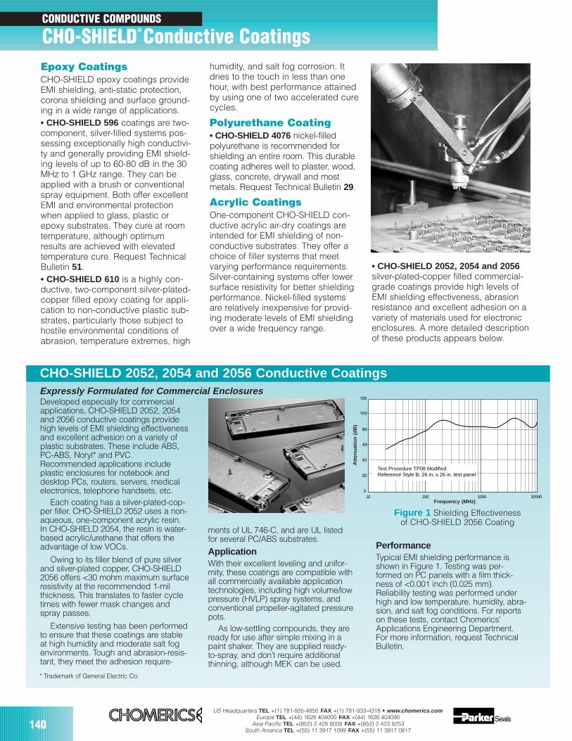
US Headquarters TEL +(1) 781-935-4850 FAX +(1) 781-933-4318 • www.chomerics.comEurope TEL +(44) 1628 404000 FAX +(44) 1628 404090
Asia Pacific TEL +(852) 2 428 8008 FAX +(852) 2 423 8253South America TEL +(55) 11 3917 1099 FAX +(55) 11 3917 0817
140
Epoxy CoatingsCHO-SHIELD epoxy coatings provideEMI shielding, anti-static protection,corona shielding and surface ground-ing in a wide range of applications.• CHO-SHIELD 596 coatings are two-component, silver-filled systems pos-sessing exceptionally high conductivi-ty and generally providing EMI shield-ing levels of up to 60-80 dB in the 30MHz to 1 GHz range. They can beapplied with a brush or conventionalspray equipment. Both offer excellentEMI and environmental protectionwhen applied to glass, plastic orepoxy substrates. They cure at roomtemperature, although optimumresults are achieved with elevatedtemperature cure. Request TechnicalBulletin 51.• CHO-SHIELD 610 is a highly con-ductive, two-component silver-plated-copper filled epoxy coating for appli-cation to non-conductive plastic sub-strates, particularly those subject tohostile environmental conditions ofabrasion, temperature extremes, high
humidity, and salt fog corrosion. Itdries to the touch in less than onehour, with best performance attainedby using one of two accelerated curecycles.
Polyurethane Coating• CHO-SHIELD 4076 nickel-filledpolyurethane is recommended forshielding an entire room. This durablecoating adheres well to plaster, wood,glass, concrete, drywall and mostmetals. Request Technical Bulletin 29.
Acrylic CoatingsOne-component CHO-SHIELD con-ductive acrylic air-dry coatings areintended for EMI shielding of non-conductive substrates. They offer achoice of filler systems that meetvarying performance requirements.Silver-containing systems offer lowersurface resistivity for better shieldingperformance. Nickel-filled systemsare relatively inexpensive for provid-ing moderate levels of EMI shieldingover a wide frequency range.
CONDUCTIVE COMPOUNDS
CHO-SHIELD® Conductive Coatings
• CHO-SHIELD 2052, 2054 and 2056silver-plated-copper filled commercial-grade coatings provide high levels ofEMI shielding effectiveness, abrasionresistance and excellent adhesion on avariety of materials used for electronicenclosures. A more detailed descriptionof these products appears below.
10 100 1000 10000
Test Procedure TP08 ModifiedReference Style B; 26 in. x 26 in. test panel
Figure 1 Shielding Effectivenessof CHO-SHIELD 2056 Coating
CHO-SHIELD 2052, 2054 and 2056 Conductive CoatingsExpressly Formulated for Commercial Enclosures
* Trademark of General Electric Co.
Developed especially for commercialapplications, CHO-SHIELD 2052, 2054and 2056 conductive coatings providehigh levels of EMI shielding effectivenessand excellent adhesion on a variety ofplastic substrates. These include ABS,PC-ABS, Noryl* and PVC.Recommended applications includeplastic enclosures for notebook anddesktop PCs, routers, servers, medicalelectronics, telephone handsets, etc.
Each coating has a silver-plated-cop-per filler. CHO-SHIELD 2052 uses a non-aqueous, one-component acrylic resin.In CHO-SHIELD 2054, the resin is water-based acrylic/urethane that offers theadvantage of low VOCs.
Owing to its filler blend of pure silverand silver-plated copper, CHO-SHIELD2056 offers <30 mohm maximum surfaceresistivity at the recommended 1-milthickness. This translates to faster cycletimes with fewer mask changes andspray passes.
Extensive testing has been performedto ensure that these coatings are stableat high humidity and moderate salt fogenvironments. Tough and abrasion-resis-tant, they meet the adhesion require-
ments of UL 746-C, and are UL listedfor several PC/ABS substrates.
ApplicationWith their excellent leveling and unifor-mity, these coatings are compatible withall commercially available applicationtechnologies, including high volume/lowpressure (HVLP) spray systems, andconventional propeller-agitated pressurepots.
As low-settling compounds, they areready for use after simple mixing in apaint shaker. They are supplied ready-to-spray, and don’t require additionalthinning, although MEK can be used.
PerformanceTypical EMI shielding performance isshown in Figure 1. Testing was per-formed on PC panels with a film thick-ness of <0.001 inch (0.025 mm).Reliability testing was performed underhigh and low temperature, humidity, abra-sion, and salt fog conditions. For reportson these tests, contact Chomerics’Applications Engineering Department.For more information, request TechnicalBulletin.
Frequency (MHz)
Atte
nuat
ion
(dB
)
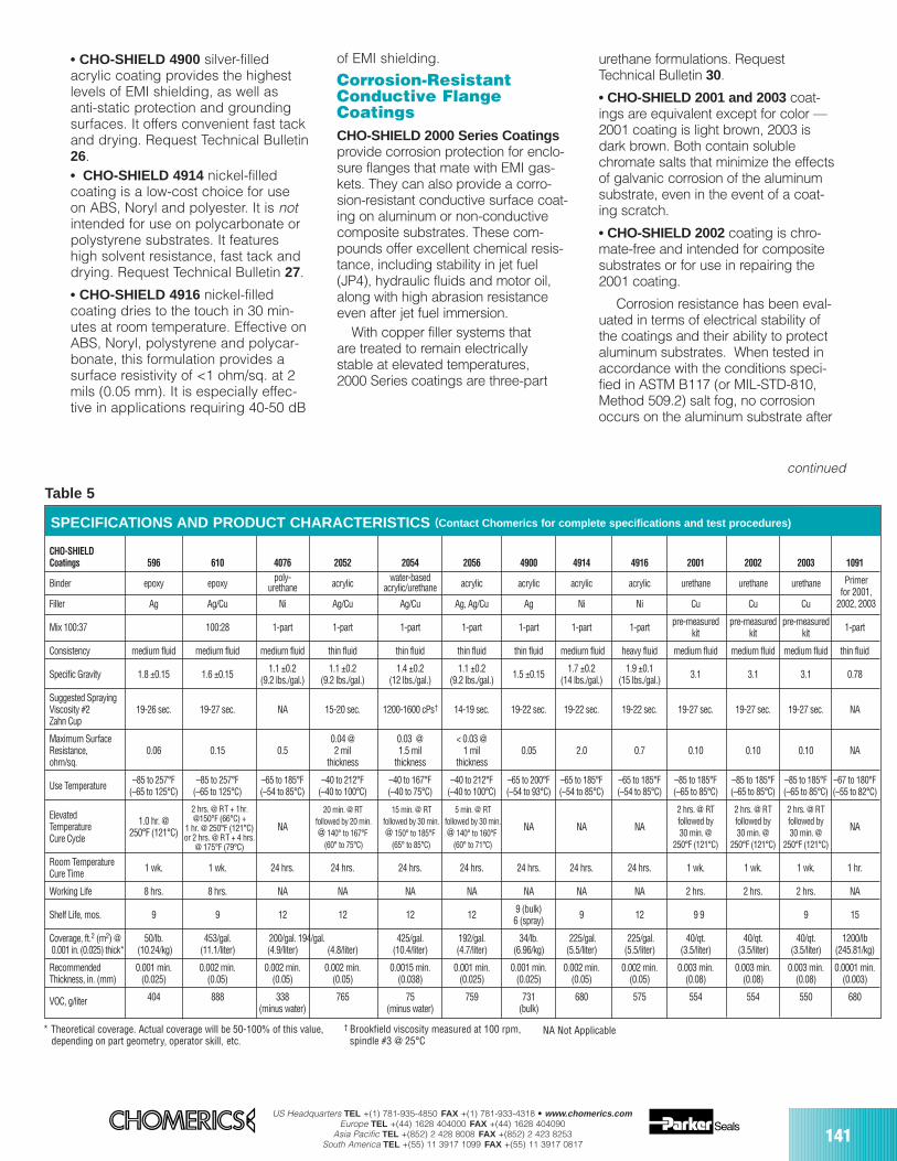
US Headquarters TEL +(1) 781-935-4850 FAX +(1) 781-933-4318 • www.chomerics.comEurope TEL +(44) 1628 404000 FAX +(44) 1628 404090
Asia Pacific TEL +(852) 2 428 8008 FAX +(852) 2 423 8253South America TEL +(55) 11 3917 1099 FAX +(55) 11 3917 0817
141
** Theoretical coverage. Actual coverage will be 50-100% of this value, depending on part geometry, operator skill, etc.
• CHO-SHIELD 4900 silver-filledacrylic coating provides the highestlevels of EMI shielding, as well asanti-static protection and groundingsurfaces. It offers convenient fast tackand drying. Request Technical Bulletin26.• CHO-SHIELD 4914 nickel-filledcoating is a low-cost choice for useon ABS, Noryl and polyester. It is notintended for use on polycarbonate orpolystyrene substrates. It featureshigh solvent resistance, fast tack anddrying. Request Technical Bulletin 27.
• CHO-SHIELD 4916 nickel-filledcoating dries to the touch in 30 min-utes at room temperature. Effective onABS, Noryl, polystyrene and polycar-bonate, this formulation provides asurface resistivity of <1 ohm/sq. at 2mils (0.05 mm). It is especially effec-tive in applications requiring 40-50 dB
of EMI shielding.
Corrosion-ResistantConductive FlangeCoatingsCHO-SHIELD 2000 Series Coatingsprovide corrosion protection for enclo-sure flanges that mate with EMI gas-kets. They can also provide a corro-sion-resistant conductive surface coat-ing on aluminum or non-conductivecomposite substrates. These com-pounds offer excellent chemical resis-tance, including stability in jet fuel(JP4), hydraulic fluids and motor oil,along with high abrasion resistanceeven after jet fuel immersion.
With copper filler systems that are treated to remain electrically stable at elevated temperatures, 2000 Series coatings are three-part
urethane formulations. RequestTechnical Bulletin 30.
• CHO-SHIELD 2001 and 2003 coat-ings are equivalent except for color —2001 coating is light brown, 2003 isdark brown. Both contain soluble chromate salts that minimize the effectsof galvanic corrosion of the aluminumsubstrate, even in the event of a coat-ing scratch.
• CHO-SHIELD 2002 coating is chro-mate-free and intended for compositesubstrates or for use in repairing the2001 coating.
Corrosion resistance has been eval-uated in terms of electrical stability ofthe coatings and their ability to protectaluminum substrates. When tested inaccordance with the conditions speci-fied in ASTM B117 (or MIL-STD-810,Method 509.2) salt fog, no corrosionoccurs on the aluminum substrate after
Table 5
Primer for 2001,
2002, 2003
CHO-SHIELD Coatings 596 610 4076 2052 2054 2056 4900 4914 4916 2001 2002 2003 1091
Binder epoxy epoxy poly- acrylic water-based acrylic acrylic acrylic acrylic urethane urethane urethaneurethane acrylic/urethane
Filler Ag Ag/Cu Ni Ag/Cu Ag/Cu Ag, Ag/Cu Ag Ni Ni Cu Cu Cu
Mix 100:37 100:28 1-part 1-part 1-part 1-part 1-part 1-part 1-part pre-measured pre-measured pre-measured 1-partkit kit kit
Consistency medium fluid medium fluid medium fluid thin fluid thin fluid thin fluid thin fluid medium fluid heavy fluid medium fluid medium fluid medium fluid thin fluid
Specific Gravity 1.8 ±0.15 1.6 ±0.15 1.1 ±0.2 1.1 ±0.2 1.4 ±0.2 1.1 ±0.2 1.5 ±0.15 1.7 ±0.2 1.9 ±0.1 3.1 3.1 3.1 0.78(9.2 lbs./gal.) (9.2 lbs./gal.) (12 lbs./gal.) (9.2 lbs./gal.) (14 lbs./gal.) (15 lbs./gal.)
Suggested SprayingViscosity #2 19-26 sec. 19-27 sec. NA 15-20 sec. 1200-1600 cPs† 14-19 sec. 19-22 sec. 19-22 sec. 19-22 sec. 19-27 sec. 19-27 sec. 19-27 sec. NAZahn Cup
Maximum Surface 0.04 @ 0.03 @ < 0.03 @Resistance, 0.06 0.15 0.5 2 mil 1.5 mil 1 mil 0.05 2.0 0.7 0.10 0.10 0.10 NAohm/sq. thickness thickness thickness
Use Temperature –85 to 257°F –85 to 257°F –65 to 185°F –40 to 212°F –40 to 167°F –40 to 212°F –65 to 200°F –65 to 185°F –65 to 185°F –85 to 185°F –85 to 185°F –85 to 185°F –67 to 180°F(–65 to 125°C) (–65 to 125°C) (–54 to 85°C) (–40 to 100°C) (–40 to 75°C) (–40 to 100°C) (–54 to 93°C) (–54 to 85°C) (–54 to 85°C) (–65 to 85°C) (–65 to 85°C) (–65 to 85°C) (–55 to 82°C)
Elevated 20 min. @ RT 15 min. @ RT 5 min. @ RT 2 hrs. @ RT 2 hrs. @ RT 2 hrs. @ RT
Temperature 1.0 hr. @ NA followed by 20 min. followed by 30 min. followed by 30 min. NA NA NA followed by followed by followed by NACure Cycle 250°F (121°C) @ 140° to 167°F @ 150° to 185°F @ 140° to 160°F 30 min. @ 30 min. @ 30 min. @
(60° to 75°C) (65° to 85°C) (60° to 71°C) 250°F (121°C) 250°F (121°C) 250°F (121°C)
Room Temperature 1 wk. 1 wk. 24 hrs. 24 hrs. 24 hrs. 24 hrs. 24 hrs. 24 hrs. 24 hrs. 1 wk. 1 wk. 1 wk. 1 hr.Cure Time
Working Life 8 hrs. 8 hrs. NA NA NA NA NA NA NA 2 hrs. 2 hrs. 2 hrs. NA
Shelf Life, mos. 9 9 12 12 12 12 9 (bulk) 9 12 9 9 9 15 6 (spray)
Coverage, ft.2 (m2) @ 50/lb. 453/gal. 200/gal. 194/gal. 425/gal. 192/gal. 34/lb. 225/gal. 225/gal. 40/qt. 40/qt. 40/qt. 1200/lb0.001 in. (0.025) thick* (10.24/kg) (11.1/liter) (4.9/liter) (4.8/liter) (10.4/liter) (4.7/liter) (6.96/kg) (5.5/liter) (5.5/liter) (3.5/liter) (3.5/liter) (3.5/liter) (245.81/kg)
Recommended 0.001 min. 0.002 min. 0.002 min. 0.002 min. 0.0015 min. 0.001 min. 0.001 min. 0.002 min. 0.002 min. 0.003 min. 0.003 min. 0.003 min. 0.0001 min.Thickness, in. (mm) (0.025) (0.05) (0.05) (0.05) (0.038) (0.025) (0.025) (0.05) (0.05) (0.08) (0.08) (0.08) (0.003)
VOC, g/liter 404 888 338 765 75 759 731 680 575 554 554 550 680(minus water) (minus water) (bulk)
SPECIFICATIONS AND PRODUCT CHARACTERISTICS (Contact Chomerics for complete specifications and test procedures)
continued
NA Not Applicable
2 hrs. @ RT + 1hr.@150°F (66°C) +
1 hr. @ 250°F (121°C)or 2 hrs. @ RT + 4 hrs.
@ 175°F (79°C)
† Brookfield viscosity measured at 100 rpm, spindle #3 @ 25°C
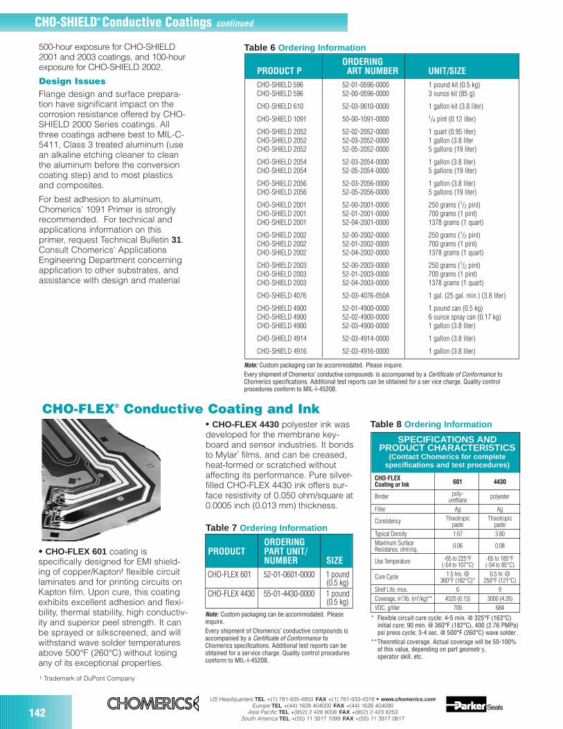
US Headquarters TEL +(1) 781-935-4850 FAX +(1) 781-933-4318 • www.chomerics.comEurope TEL +(44) 1628 404000 FAX +(44) 1628 404090
Asia Pacific TEL +(852) 2 428 8008 FAX +(852) 2 423 8253South America TEL +(55) 11 3917 1099 FAX +(55) 11 3917 0817
142
ORDERINGPRODUCT P ART NUMBER UNIT/SIZECHO-SHIELD 596 52-01-0596-0000 1 pound kit (0.5 kg)CHO-SHIELD 596 52-00-0596-0000 3 ounce kit (85 g)
CHO-SHIELD 610 52-03-0610-0000 1 gallon kit (3.8 liter)
CHO-SHIELD 1091 50-00-1091-0000 1/4 pint (0.12 liter)
CHO-SHIELD 2052 52-02-2052-0000 1 quart (0.95 liter)CHO-SHIELD 2052 52-03-2052-0000 1 gallon (3.8 literCHO-SHIELD 2052 52-05-2052-0000 5 gallons (19 liter)
CHO-SHIELD 2054 52-03-2054-0000 1 gallon (3.8 liter)CHO-SHIELD 2054 52-05-2054-0000 5 gallons (19 liter)
CHO-SHIELD 2056 52-03-2056-0000 1 gallon (3.8 liter)CHO-SHIELD 2056 52-05-2056-0000 5 gallons (19 liter)
CHO-SHIELD 2001 52-00-2001-0000 250 grams (1/2 pint)CHO-SHIELD 2001 52-01-2001-0000 700 grams (1 pint)CHO-SHIELD 2001 52-04-2001-0000 1378 grams (1 quart)
CHO-SHIELD 2002 52-00-2002-0000 250 grams (1/2 pint)CHO-SHIELD 2002 52-01-2002-0000 700 grams (1 pint)CHO-SHIELD 2002 52-04-2002-0000 1378 grams (1 quart)
CHO-SHIELD 2003 52-00-2003-0000 250 grams (1/2 pint)CHO-SHIELD 2003 52-01-2003-0000 700 grams (1 pint)CHO-SHIELD 2003 52-04-2003-0000 1378 grams (1 quart)
CHO-SHIELD 4076 52-03-4076-050A 1 gal. (25 gal. min.) (3.8 liter)
CHO-SHIELD 4900 52-01-4900-0000 1 pound can (0.5 kg)CHO-SHIELD 4900 52-02-4900-0000 6 ounce spray can (0.17 kg)CHO-SHIELD 4900 52-03-4900-0000 1 gallon (3.8 liter)
CHO-SHIELD 4914 52-03-4914-0000 1 gallon (3.8 liter)
CHO-SHIELD 4916 52-03-4916-0000 1 gallon (3.8 liter)
• CHO-FLEX 601 coating isspecifically designed for EMI shield-ing of copper/Kapton† flexible circuitlaminates and for printing circuits onKapton film. Upon cure, this coatingexhibits excellent adhesion and flexi-bility, thermal stability, high conductiv-ity and superior peel strength. It canbe sprayed or silkscreened, and willwithstand wave solder temperaturesabove 500°F (260°C) without losingany of its exceptional properties.
* Flexible circuit cure cycle: 4-5 min. @ 325°F (163°C) initial cure; 90 min. @ 360°F (182°C), 400 (2.76 PMPa) psi press cycle; 3-4 sec. @ 500°F (260°C) wave solder .
**Theoretical coverage. Actual coverage will be 50-100% of this value, depending on part geometr y, operator skill, etc.
SPECIFICATIONS AND PRODUCT CHARACTERISTICS
(Contact Chomerics for complete specifications and test procedures)
Note: Custom packaging can be accommodated. Pleaseinquire.Every shipment of Chomerics’ conductive compounds isaccompanied by a Certificate of Conformance toChomerics specifications. Additional test reports can beobtained for a service charge. Quality control proceduresconform to MIL-I-45208.
ORDERINGPRODUCT PART UNIT/
NUMBER SIZE
† Trademark of DuPont Company
Note: Custom packaging can be accommodated. Please inquire.Every shipment of Chomerics’ conductive compounds is accompanied by a Certificate of Conformance toChomerics specifications. Additional test reports can be obtained for a ser vice charge. Quality controlprocedures conform to MIL-I-45208.
500-hour exposure for CHO-SHIELD2001 and 2003 coatings, and 100-hourexposure for CHO-SHIELD 2002.
Design IssuesFlange design and surface prepara-tion have significant impact on thecorrosion resistance offered by CHO-SHIELD 2000 Series coatings. Allthree coatings adhere best to MIL-C-5411, Class 3 treated aluminum (usean alkaline etching cleaner to cleanthe aluminum before the conversioncoating step) and to most plasticsand composites.
For best adhesion to aluminum,Chomerics’ 1091 Primer is stronglyrecommended. For technical andapplications information on thisprimer, request Technical Bulletin 31.Consult Chomerics’ ApplicationsEngineering Department concerningapplication to other substrates, andassistance with design and material
CHO-SHIELD® Conductive Coatings continued
CHO-FLEXCoating or Ink 601 4430
Binder poly- polyesterurethaneFiller Ag Ag
Consistency Thixotropic Thixotropicpaste paste
Typical Density 1.67 3.80Maximum Surface 0.06 0.08Resistance, ohm/sq.
Use Temperature -65 to 225°F -65 to 185°F(-54 to 107°C) (-54 to 85°C)
Cure Cycle 1.5 hrs. @ 0.5 hr. @360°F (182°C)* 250°F (121°C)
Shelf Life, mos. 6 9Coverage, in2/lb. (m2/kg)** 4320 (6.13) 3000 (4.26)VOC, g/liter 709 684
CHO-FLEX 601 52-01-0601-0000 1 pound(0.5 kg)
CHO-FLEX 4430 55-01-4430-0000 1 pound(0.5 kg)
CHO-FLEX® Conductive Coating and Ink• CHO-FLEX 4430 polyester ink wasdeveloped for the membrane key-board and sensor industries. It bondsto Mylar† films, and can be creased,heat-formed or scratched withoutaffecting its performance. Pure silver-filled CHO-FLEX 4430 ink offers sur-face resistivity of 0.050 ohm/square at0.0005 inch (0.013 mm) thickness.
Table 6 Ordering Information
Table 7 Ordering Information
Table 8 Ordering Information
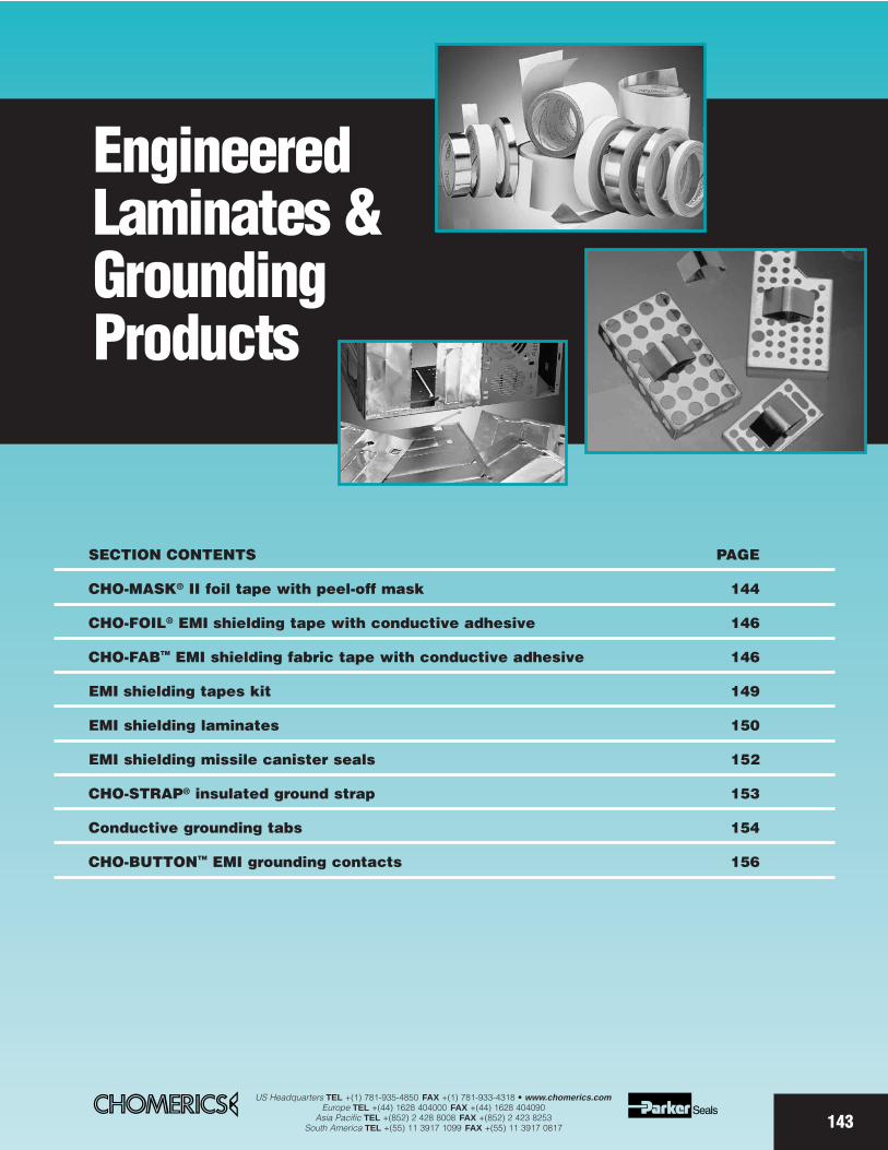
SECTION CONTENTS PAGE
CHO-MASK® II foil tape with peel-off mask 144
CHO-FOIL® EMI shielding tape with conductive adhesive 146
CHO-FABTM EMI shielding fabric tape with conductive adhesive 146
EMI shielding tapes kit 149
EMI shielding laminates 150
EMI shielding missile canister seals 152
CHO-STRAP® insulated ground strap 153
Conductive grounding tabs 154
CHO-BUTTONTM EMI grounding contacts 156
EngineeredLaminates &GroundingProducts
143
US Headquarters TEL +(1) 781-935-4850 FAX +(1) 781-933-4318 • www.chomerics.comEurope TEL +(44) 1628 404000 FAX +(44) 1628 404090
Asia Pacific TEL +(852) 2 428 8008 FAX +(852) 2 423 8253South America TEL +(55) 11 3917 1099 FAX +(55) 11 3917 0817
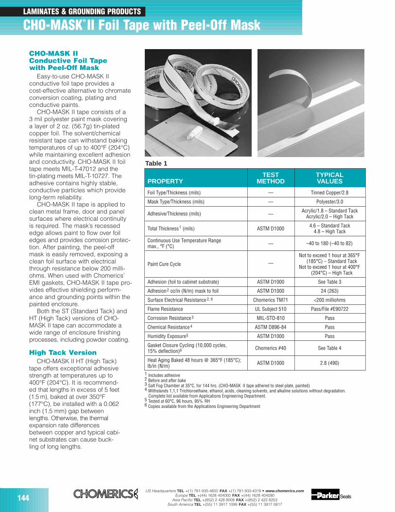
144US Headquarters TEL +(1) 781-935-4850 FAX +(1) 781-933-4318 • www.chomerics.com
Europe TEL +(44) 1628 404000 FAX +(44) 1628 404090Asia Pacific TEL +(852) 2 428 8008 FAX +(852) 2 423 8253
South America TEL +(55) 11 3917 1099 FAX +(55) 11 3917 0817
CHO-MASK IIConductive Foil Tapewith Peel-Off Mask
Easy-to-use CHO-MASK IIconductive foil tape provides acost-effective alternative to chromateconversion coating, plating andconductive paints.
CHO-MASK II tape consists of a3 mil polyester paint mask coveringa layer of 2 oz. (56.7g) tin-platedcopper foil. The solvent/chemicalresistant tape can withstand bakingtemperatures of up to 400°F (204°C)while maintaining excellent adhesionand conductivity. CHO-MASK II foiltape meets MIL-T-47012 and thetin-plating meets MIL-T-10727. Theadhesive contains highly stable,conductive particles which providelong-term reliability.
CHO-MASK II tape is applied toclean metal frame, door and panelsurfaces where electrical continuityis required. The mask’s recessededge allows paint to flow over foiledges and provides corrosion protec-tion. After painting, the peel-offmask is easily removed, exposing aclean foil surface with electricalthrough resistance below 200 milli-ohms. When used with Chomerics’EMI gaskets, CHO-MASK II tape pro-vides effective shielding perform-ance and grounding points within thepainted enclosure.
Both the ST (Standard Tack) andHT (High Tack) versions of CHO-MASK II tape can accommodate awide range of enclosure finishingprocesses, including powder coating.
TEST TYPICALPROPERTY METHOD VALUES
Foil Type/Thickness (mils) — Tinned Copper/2.8
Mask Type/Thickness (mils) — Polyester/3.0
Adhesive/Thickness (mils) Acrylic/1.8 – Standard Tack— Acrylic/2.0 – High Tack
Total Thickness1 (mils) ASTM D1000 4.6 – Standard Tack4.8 – High Tack
Continuous Use Temperature Rangemax., °F (°C) — –40 to 180 (–40 to 82)
Not to exceed 1 hour at 365°F
Paint Cure Cycle — (185°C) – Standard TackNot to exceed 1 hour at 400°F
(204°C) – High Tack
Adhesion (foil to cabinet substrate) ASTM D1000 See Table 3
Adhesion2 oz/in (N/m) mask to foil ASTM D1000 24 (263)
Surface Electrical Resistance 2, 6 Chomerics TM71 <200 milliohms
Flame Resistance UL Subject 510 Pass/File #E90722
Corrosion Resistance 3 MIL-STD-810 Pass
Chemical Resistance 4 ASTM D896-84 Pass
Humidity Exposure5 ASTM D1000 Pass
Gasket Closure Cycling (10,000 cycles,15% deflection)6 Chomerics #40 See Table 4
Heat Aging Baked 48 hours @ 365°F (185°C);lb/in (N/m) ASTM D1000 2.8 (490)
1 Includes adhesive2 Before and after bake3 Salt Fog Chamber at 35°C, for 144 hrs. (CHO-MASK II tape adhered to steel plate, painted)4 Withstands 1,1,1 Trichloroethane, ethanol, acids, cleaning solvents, and alkaline solutions without degradation.
Complete list available from Applications Engineering Department.5 Tested at 60°C, 96 hours, 95% RH6 Copies available from the Applications Engineering Department
High Tack VersionCHO-MASK II HT (High Tack)
tape offers exceptional adhesivestrength at temperatures up to400°F (204°C). It is recommend-ed that lengths in excess of 5 feet(1.5 m), baked at over 350°F(177°C), be installed with a 0.062inch (1.5 mm) gap betweenlengths. Otherwise, the thermalexpansion rate differencesbetween copper and typical cabi-net substrates can cause buck-ling of long lengths.
Table 1
LAMINATES & GROUNDING PRODUCTS
CHO-MASK® II Foil Tape with Peel-Off Mask
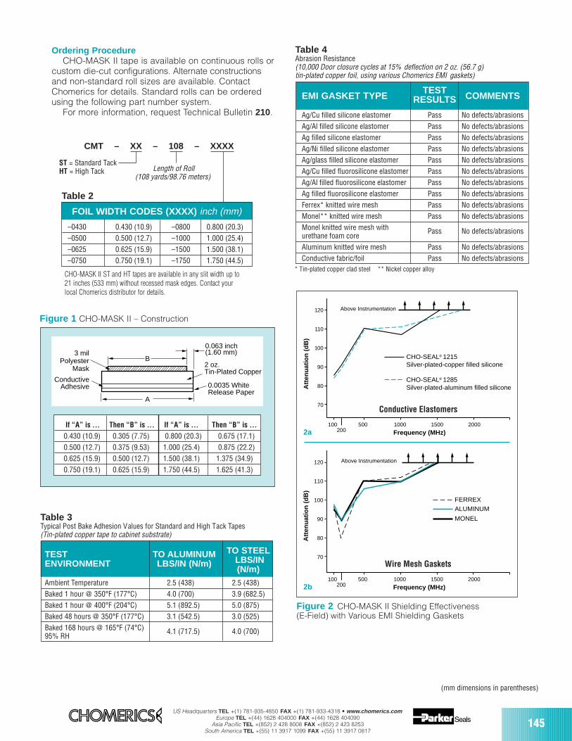
US Headquarters TEL +(1) 781-935-4850 FAX +(1) 781-933-4318 • www.chomerics.comEurope TEL +(44) 1628 404000 FAX +(44) 1628 404090
Asia Pacific TEL +(852) 2 428 8008 FAX +(852) 2 423 8253South America TEL +(55) 11 3917 1099 FAX +(55) 11 3917 0817
145
CMT – XX – 108 – XXXX
ST = Standard TackHT = High Tack Length of Roll
FOIL WIDTH CODES (XXXX) inch (mm)
–0430 0.430 (10.9) –0800 0.800 (20.3)–0500 0.500 (12.7) –1000 1.000 (25.4)–0625 0.625 (15.9) –1500 1.500 (38.1)–0750 0.750 (19.1) –1750 1.750 (44.5)
Figure 2 CHO-MASK II Shielding Effectiveness(E-Field) with Various EMI Shielding Gaskets
500
70
80
90
100
110
120
200100 1000 1500 2000
Above InstrumentationA
tten
uat
ion
(d
B)
Frequency (MHz)
CHO-SEAL® 1285Silver-plated-aluminum filled silicone
CHO-SEAL® 1215Silver-plated-copper filled silicone
500
70
80
90
100
110
120
200100 1000 1500 2000
Above Instrumentation
Att
enu
atio
n (
dB
)
Frequency (MHz)
FERREXALUMINUM
MONELTable 3Typical Post Bake Adhesion Values for Standard and High Tack Tapes(Tin-plated copper tape to cabinet substrate)
TEST TO ALUMINUM TO STEELENVIRONMENT LBS/IN (N/m) LBS/IN
(N/m)Ambient Temperature 2.5 (438) 2.5 (438)Baked 1 hour @ 350°F (177°C) 4.0 (700) 3.9 (682.5)Baked 1 hour @ 400°F (204°C) 5.1 (892.5) 5.0 (875)Baked 48 hours @ 350°F (177°C) 3.1 (542.5) 3.0 (525)Baked 168 hours @ 165°F (74°C) 4.1 (717.5) 4.0 (700)95% RH
Table 4Abrasion Resistance(10,000 Door closure cycles at 15% deflection on 2 oz. (56.7 g)tin-plated copper foil, using various Chomerics EMI gaskets)
TESTEMI GASKET TYPE RESULTS COMMENTS
Ag/Cu filled silicone elastomer Pass No defects/abrasionsAg/Al filled silicone elastomer Pass No defects/abrasionsAg filled silicone elastomer Pass No defects/abrasionsAg/Ni filled silicone elastomer Pass No defects/abrasionsAg/glass filled silicone elastomer Pass No defects/abrasionsAg/Cu filled fluorosilicone elastomer Pass No defects/abrasionsAg/Al filled fluorosilicone elastomer Pass No defects/abrasionsAg filled fluorosilicone elastomer Pass No defects/abrasionsFerrex* knitted wire mesh Pass No defects/abrasionsMonel** knitted wire mesh Pass No defects/abrasionsMonel knitted wire mesh with Pass No defects/abrasionsurethane foam coreAluminum knitted wire mesh Pass No defects/abrasionsConductive fabric/foil Pass No defects/abrasions
* Tin-plated copper clad steel ** Nickel copper alloy
B
A
2 oz. Tin-Plated Copper
0.0035 WhiteRelease Paper
0.063 inch(1.60 mm)3 mil
PolyesterMask
ConductiveAdhesive
If “A” is … Then “B” is … If “A” is … Then “B” is …
0.430 (10.9) 0.305 (7.75) 0.800 (20.3) 0.675 (17.1)0.500 (12.7) 0.375 (9.53) 1.000 (25.4) 0.875 (22.2)0.625 (15.9) 0.500 (12.7) 1.500 (38.1) 1.375 (34.9)0.750 (19.1) 0.625 (15.9) 1.750 (44.5) 1.625 (41.3)
Figure 1 CHO-MASK II – Construction
2a
2b
Table 2
Conductive Elastomers
Wire Mesh Gaskets
CHO-MASK II ST and HT tapes are available in any slit width up to21 inches (533 mm) without recessed mask edges. Contact yourlocal Chomerics distributor for details.
(mm dimensions in parentheses)
(108 yards/98.76 meters)
Ordering ProcedureCHO-MASK II tape is available on continuous rolls or
custom die-cut configurations. Alternate constructionsand non-standard roll sizes are available. ContactChomerics for details. Standard rolls can be orderedusing the following part number system.
For more information, request Technical Bulletin 210.
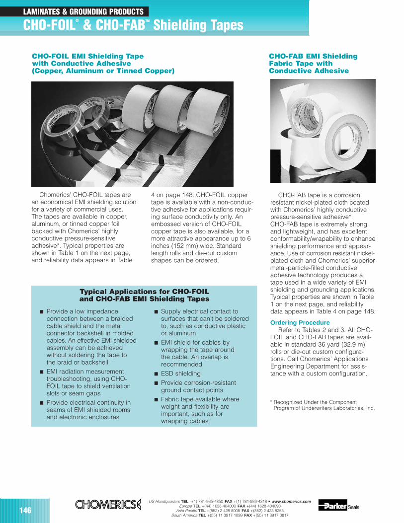
146US Headquarters TEL +(1) 781-935-4850 FAX +(1) 781-933-4318 • www.chomerics.com
Europe TEL +(44) 1628 404000 FAX +(44) 1628 404090Asia Pacific TEL +(852) 2 428 8008 FAX +(852) 2 423 8253
South America TEL +(55) 11 3917 1099 FAX +(55) 11 3917 0817
Chomerics’ CHO-FOIL tapes arean economical EMI shielding solutionfor a variety of commercial uses.The tapes are available in copper,aluminum, or tinned copper foilbacked with Chomerics’ highlyconductive pressure-sensitiveadhesive*. Typical properties areshown in Table 1 on the next page,and reliability data appears in Table
* Recognized Under the ComponentProgram of Underwriters Laboratories, Inc.
CHO-FAB tape is a corrosionresistant nickel-plated cloth coatedwith Chomerics’ highly conductivepressure-sensitive adhesive*.CHO-FAB tape is extremely strongand lightweight, and has excellentconformability/wrapability to enhanceshielding performance and appear-ance. Use of corrosion resistant nickel-plated cloth and Chomerics’ superiormetal-particle-filled conductive adhesive technology produces atape used in a wide variety of EMIshielding and grounding applications.Typical properties are shown in Table1 on the next page, and reliabilitydata appears in Table 4 on page 148.
Ordering ProcedureRefer to Tables 2 and 3. All CHO-
FOIL and CHO-FAB tapes are avail-able in standard 36 yard (32.9 m)rolls or die-cut custom configura-tions. Call Chomerics’ ApplicationsEngineering Department for assis-tance with a custom configuration.
4 on page 148. CHO-FOIL coppertape is available with a non-conduc-tive adhesive for applications requir-ing surface conductivity only. Anembossed version of CHO-FOIL copper tape is also available, for amore attractive appearance up to 6inches (152 mm) wide. Standardlength rolls and die-cut customshapes can be ordered.
Provide a low impedanceconnection between a braidedcable shield and the metalconnector backshell in moldedcables. An effective EMI shieldedassembly can be achievedwithout soldering the tape tothe braid or backshell
EMI radiation measurementtroubleshooting, using CHO-FOIL tape to shield ventilationslots or seam gaps
Provide electrical continuity inseams of EMI shielded roomsand electronic enclosures
Supply electrical contact to surfaces that can’t be solderedto, such as conductive plasticor aluminum
EMI shield for cables bywrapping the tape aroundthe cable. An overlap isrecommended
ESD shielding Provide corrosion-resistant
ground contact points Fabric tape available where
weight and flexibility areimportant, such as forwrapping cables
CHO-FOIL EMI Shielding Tapewith Conductive Adhesive(Copper, Aluminum or Tinned Copper)
CHO-FAB EMI ShieldingFabric Tape withConductive Adhesive
Typical Applications for CHO-FOILand CHO-FAB EMI Shielding Tapes
LAMINATES & GROUNDING PRODUCTS
CHO-FOIL® & CHO-FABTM Shielding Tapes
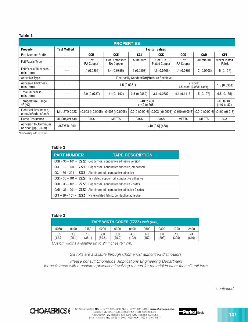
US Headquarters TEL +(1) 781-935-4850 FAX +(1) 781-933-4318 • www.chomerics.comEurope TEL +(44) 1628 404000 FAX +(44) 1628 404090
Asia Pacific TEL +(852) 2 428 8008 FAX +(852) 2 423 8253South America TEL +(55) 11 3917 1099 FAX +(55) 11 3917 0817
147
Table 2
TAPE WIDTH CODES (ZZZZ) inch (mm)
PART NUMBER TAPE DESCRIPTION
CCH – 36 – 101 – ZZZZ Copper foil, conductive adhesive version
CCE – 36 – 101 – ZZZZ Copper foil, conductive adhesive, embossed
CCJ – 36 – 201 – ZZZZ Aluminum foil, conductive adhesive
CCK – 36 – 101 – ZZZZ Tin-plated copper foil, conductive adhesive
CCD – 36 – 101 – ZZZZ Copper foil, conductive adhesive 2 sides
CAD – 36 – 201 – ZZZZ Aluminum foil, conductive adhesive 2 sides
CFT – 36 – 101 – ZZZZ Nickel-plated fabric, conductive adhesive
0050 0100 0150 0200 0300 0400 0600 0800 1200 2400
0.5 1.0 1.5 2.0 3.0 4.0 6.0 8.0 12 24(12.7) (25.4) (38.1) (50.8) (76.2) (102) (152) (203) (305) (610)
Table 3
Property Test Method Typical Values
Part Number Prefix –– CCH CCE CCJ CCK CCD CAD CFT
Foil/Fabric Type –– 1 oz. 1 oz. Embossed Aluminum 1 oz. Tin- 1 oz. Aluminum Nickel-PlatedRA Copper RA Copper Plated Copper RA Copper Fabric
Foil/Fabric Thickness, –– 1.4 (0.0356) 1.4 (0.0356) 2 (0.0508) 1.6 (0.0406) 1.4 (0.0356) 2 (0.0508) 5 (0.127)mils (mm)
Adhesive Type –– Electrically Conductive, Acrylic Pressure- Sensitive
Adhesive Thickness, –– 1.5 (0.0381) 2 sides:mils (mm) 1.5 each (0.0381 each) 1.5 (0.0381)
Total Thickness, –– 2.9 (0.0737) 4* (0.1102) 3.5 (0.0889) 3.1 (0.0787) 4.4 (0.1118) 5 (0.127) 6.5 (0.165)mils (mm)
Temperature Range, __ –40 to 400 –40 to 180°F (°C) (–40 to 205) (–40 to 82)
Electrical Resistance, MIL-STD-202C <0.003 (<0.0005) (<0.0005) <0.010 (<0.0016) <0.010 (<0.0016) <0.010 (<0.0016)<0.003 (<0.0005) <0.100 (<0.016)ohms/in2 (ohms/cm2)
Flame Resistance UL Subject 510 PASS MEETS PASS PASS MEETS MEETS N/A
Adhesion to Aluminum ASTM D1000 >40 [2.5] (438)oz./inch [ppi] (N/m)
PROPERTIES
<0.003
Table 1
Slit rolls are available through Chomerics' authorized distributors.
Please consult Chomerics’ Applications Engineering Departmentfor assistance with a custom application involving a need for material in other than slit roll form.
continued
Custom widths available up to 24 inches (61 cm)
*Embossing adds 1.1 mil
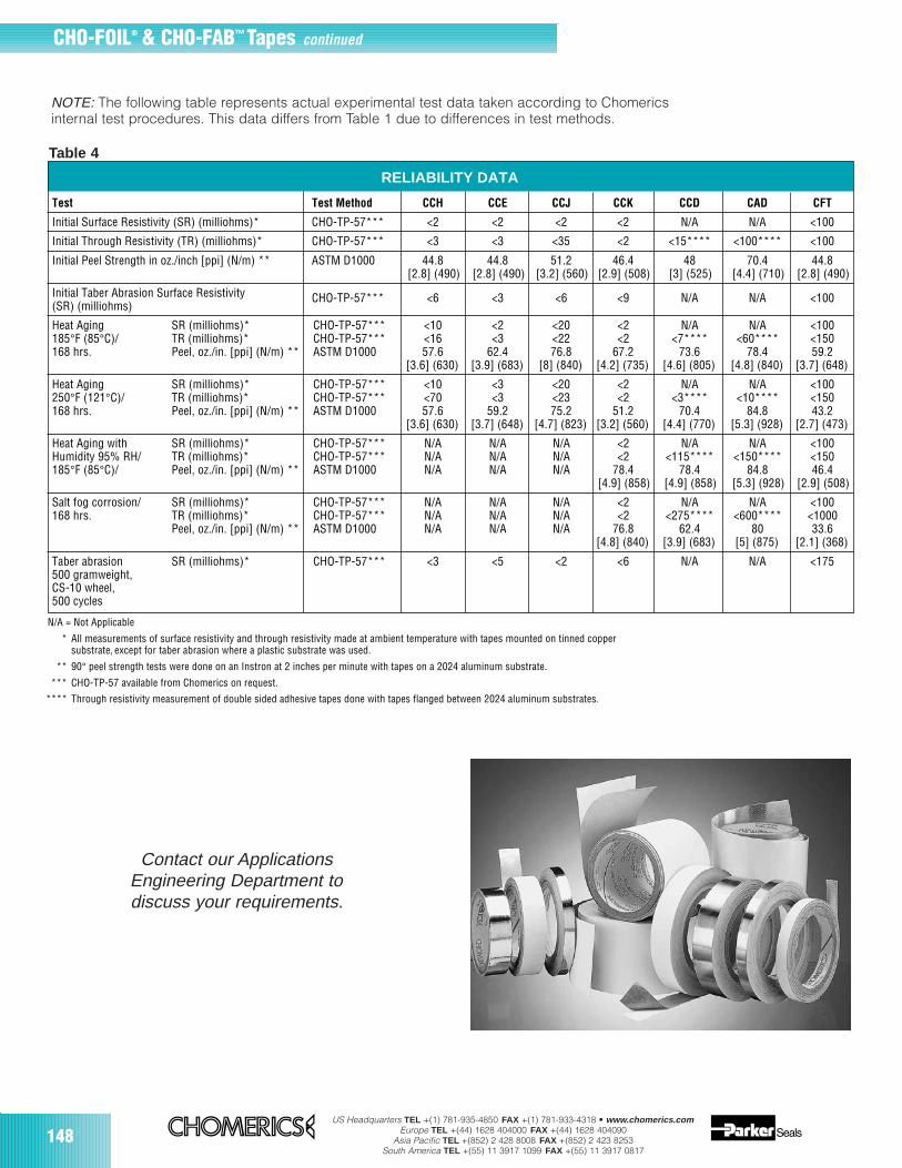
148US Headquarters TEL +(1) 781-935-4850 FAX +(1) 781-933-4318 • www.chomerics.com
Europe TEL +(44) 1628 404000 FAX +(44) 1628 404090Asia Pacific TEL +(852) 2 428 8008 FAX +(852) 2 423 8253
South America TEL +(55) 11 3917 1099 FAX +(55) 11 3917 0817
Test Test Method CCH CCE CCJ CCK CCD CAD CFT
Initial Surface Resistivity (SR) (milliohms)* CHO-TP-57*** <2 <2 <2 <2 N/A N/A <100
Initial Through Resistivity (TR) (milliohms)* CHO-TP-57*** <3 <3 <35 <2 <15**** <100**** <100
Initial Peel Strength in oz./inch [ppi] (N/m) ** ASTM D1000 44.8 44.8 51.2 46.4 48 70.4 44.8[2.8] (490) [2.8] (490) [3.2] (560) [2.9] (508) [3] (525) [4.4] (710) [2.8] (490)
Initial Taber Abrasion Surface Resistivity(SR) (milliohms)
CHO-TP-57*** <6 <3 <6 <9 N/A N/A <100
Heat Aging SR (milliohms)* CHO-TP-57*** <10 <2 <20 <2 N/A N/A <100185°F (85°C)/ TR (milliohms)* CHO-TP-57*** <16 <3 <22 <2 <7**** <60**** <150168 hrs. Peel, oz./in. [ppi] (N/m) ** ASTM D1000 57.6 62.4 76.8 67.2 73.6 78.4 59.2
[3.6] (630) [3.9] (683) [8] (840) [4.2] (735) [4.6] (805) [4.8] (840) [3.7] (648)
Heat Aging SR (milliohms)* CHO-TP-57*** <10 <3 <20 <2 N/A N/A <100250°F (121°C)/ TR (milliohms)* CHO-TP-57*** <70 <3 <23 <2 <3**** <10**** <150168 hrs. Peel, oz./in. [ppi] (N/m) ** ASTM D1000 57.6 59.2 75.2 51.2 70.4 84.8 43.2
[3.6] (630) [3.7] (648) [4.7] (823) [3.2] (560) [4.4] (770) [5.3] (928) [2.7] (473)
Heat Aging with SR (milliohms)* CHO-TP-57*** N/A N/A N/A <2 N/A N/A <100Humidity 95% RH/ TR (milliohms)* CHO-TP-57*** N/A N/A N/A <2 <115**** <150**** <150185°F (85°C)/ Peel, oz./in. [ppi] (N/m) ** ASTM D1000 N/A N/A N/A 78.4 78.4 84.8 46.4
[4.9] (858) [4.9] (858) [5.3] (928) [2.9] (508)
Salt fog corrosion/ SR (milliohms)* CHO-TP-57*** N/A N/A N/A <2 N/A N/A <100168 hrs. TR (milliohms)* CHO-TP-57*** N/A N/A N/A <2 <275**** <600**** <1000
Peel, oz./in. [ppi] (N/m) ** ASTM D1000 N/A N/A N/A 76.8 62.4 80 33.6[4.8] (840) [3.9] (683) [5] (875) [2.1] (368)
Taber abrasion SR (milliohms)* CHO-TP-57*** <3 <5 <2 <6 N/A N/A <175500 gramweight,CS-10 wheel,500 cycles
N/A = Not Applicable
* All measurements of surface resistivity and through resistivity made at ambient temperature with tapes mounted on tinned coppersubstrate, except for taber abrasion where a plastic substrate was used.
** 90° peel strength tests were done on an Instron at 2 inches per minute with tapes on a 2024 aluminum substrate.
*** CHO-TP-57 available from Chomerics on request.
**** Through resistivity measurement of double sided adhesive tapes done with tapes flanged between 2024 aluminum substrates.
RELIABILITY DATA
Table 4
NOTE: The following table represents actual experimental test data taken according to Chomericsinternal test procedures. This data differs from Table 1 due to differences in test methods.
Contact our ApplicationsEngineering Department todiscuss your requirements.
CHO-FOIL® & CHO-FAB™ Tapes continued

US Headquarters TEL +(1) 781-935-4850 FAX +(1) 781-933-4318 • www.chomerics.comEurope TEL +(44) 1628 404000 FAX +(44) 1628 404090
Asia Pacific TEL +(852) 2 428 8008 FAX +(852) 2 423 8253South America TEL +(55) 11 3917 1099 FAX +(55) 11 3917 0817
EMI Shielding Tapes KitChomerics’ EMI Shielding Tapes
Kit is a benchtop box containing six1 inch x 36 yard (2.54 cm x 32.9 m)rolls of conductive foil and fabrictapes. It is designed to provide awide range of price, performanceand application options in a single,easy-to-use package.
The Kit includes copper, aluminumand tin-plated copper CHO-FOIL®shielding tapes. Their conductivepressure-sensitive adhesive providesvery low electrical resistance throughthe tape, resulting in higher shieldingperformance than typical metal foiltapes. Both embossed and smoothversions are included.
CHO-FABTM shielding tape, alsoincluded in the benchtop kit, consistsof a corrosion resistant, nickel-platedfabric with a highly conductive pres-sure-sensitive adhesive. CHO-FABtape is lightweight and flexible, whichmakes it ideal as an EMI shield towrap over cables. The ChomericsEMI Shielding Tapes Kit provides aconvenient resource for EMI measure-ment trouble-shooting, cable shieldingand any other application where on-the-spot solutions are needed. Itcomes with a pair of 3 inch (7.62 cm)metal blade Fiskars* scissors.
Ordering ProcedureTo place an order for the EMI
Shielding Tapes Kit, contact yourlocal Chomerics distributor andask for:
* Fiskars, Inc., Wausau, WI.
Chomerics EMI Shielding Tapes KitPart Number: CHO-EMI-TAPE-BOX
CHO-FOIL(CCJ-201)
0.002 in. (0.051 mm)thick, electrical grade,dead-soft aluminum foilwith electrically conductiveacrylic adhesive
0.0035 in. (0.089 mm)total thickness (excludingrelease liner)
<10 milliohms electricalthrough resistance(MIL-STD-202C)
>40 oz./in. (>0.44 kN/m)minimum adhesion
CHO-FOIL(CCH-101)
0.0014 in. (0.036 mm)thick, fully annealed copper foil with electricallyconductive acrylic adhesive
0.0029 in. (0.074 mm)total thickness (excludingrelease liner)
<3 milliohms electricalthrough resistance(MIL-STD-202C)
>40 oz./in. (>0.44 kN/m)minimum adhesion
CHO-FOIL(CCE-101)
0.0014 in. (0.036 mm)thick, embossed, fullyannealed copper foil withelectrically conductiveacrylic adhesive
0.004 in. (0.102 mm) totalthickness (excludingrelease liner)
<3 milliohms electricalthrough resistance(MIL-STD-202C)
>40 oz./in. (>0.44 kN/m)minimum adhesion
CHO-FAB(CFT-101)
0.005 in. (0.127 mm) thick,nickel-plated fabric withelectrically conductiveacrylic adhesive
0.0065 in. (0.165 mm) totalthickness (excluding releaseliner)
<100 milliohms electricalthrough resistance(MIL-STD-202C)
>40 oz./in. (>0.44 kN/m)minimum adhesion
CHO-FOIL(CAD-201)
0.002 in. (0.051 mm) thick,electrical grade, dead-softaluminum foil with electri-cally conductive acrylicadhesive on both sides
0.005 in. (0.127 mm) totalthickness (excludingrelease liner)
<10 milliohms electricalthrough resistance(MIL-STD-202C)
>40 oz./in. (>0.44 kN/m)minimum adhesion
CHO-FOIL(CCK-101)
0.0016 in. (0.041 mm)thick, tin-plated copper foilwith electrically conductiveacrylic adhesive
0.0031 in. (0.079 mm)total thickness (excludingrelease liner)
<3 milliohms electricalthrough resistance(MIL-STD-202C)
>40 oz./in. (>0.44 kN/m)minimum adhesion
For information on how to orderindividual rolls of the tapes containedin this kit, please refer to the preced-ing pages.
Table 1 Kit Contents
LAMINATES & GROUNDING PRODUCTS
EMI Shielding Tapes Kit
149

150US Headquarters TEL +(1) 781-935-4850 FAX +(1) 781-933-4318 • www.chomerics.com
Europe TEL +(44) 1628 404000 FAX +(44) 1628 404090Asia Pacific TEL +(852) 2 428 8008 FAX +(852) 2 423 8253
South America TEL +(55) 11 3917 1099 FAX +(55) 11 3917 0817
EMI Shielding LaminatesMechanical, electrical andprocessing properties, pluseconomy for commercialapplications.
Chomerics produces a growing fam-ily of specialty laminated materials forEMI shielding. These laminates areavailable in bulk rolls for customizinginto EMI shields, ground planes,ground straps, shadow shields, ESDshields and a host of other electronicsapplications. EMI shielding perform-ance exceeds that of conductive coat-ings when properly designed.
Laminates provide an environmen-tally friendly solution that eliminates solvents, conductive paints, or platingprocesses. With their thin crosssections and light weight, EMI shield-ing laminates are also a space-savingsolution.
ConstructionShielding laminates are made from
a variety of raw materials, includingcopper and aluminum foils, conduc-tive and non-conductive acrylic pres-sure-sensitive adhesives (PSAs) anddielectric films such as PVC and poly-ester. Flame retardant materials areavailable, meeting the requirements ofUL 94V-0 (UL File No. E140244).
The metal foil layer supplies thenecessary EMI shielding (generally20-60 dB depending on frequency,size, configuration and installation*)and grounding properties. Thedielectric layer provides isolation andflexibility.
Electrically Conductive AttachmentAdhesive
A conductive, metal particle-filledacrylic pressure-sensitive adhesivecan be provided as a simple andcost effective method for shield termi-nation to ground. The acrylic PSAcontains a uniform dispersion ofunique, oxidation-resistant conductiveparticles that create a very low elec-trical resistance through the shield.Peel strength of the conductivePSA typically exceeds 40 oz./inch(446 g/cm); non-conductives typicallyexceed 64 oz./inch (714 g/cm).
Releasable Dielectric Layer withElectrically Conductive AdhesiveSimplifies Grounding and Bonding
Chomerics has developed aunique EMI shielding laminateconsisting of an aluminum foil anda dielectric film layer. Sections ofthe dielectric layer are kiss-cut sothey can be selectively removed toexpose the electrically conductivePSA and foil (Figure 1). This featureprovides choices for grounding/bonding sites, and eliminates theneed for selective lamination, inwhich parts are fabricated withexposed metal foil sites.
Complete Customization CapabilitiesTo enhance installation of these
EMI shielding laminates, scores, slits,self-adhesive mounting strips, creasesand other features are easily designedinto the part.
Chomerics routinely produceslaminates with complex die-cutsas well as punched and stampedfeatures.
Contact Chomerics' ApplicationsEngineering Department to evaluateyour needs and develop a cost-effective shielding solution.
* To determine the shielding effectiveness ofspecific laminate parts, it is recommended thatprototype shields be inserted and properlyterminated in the product under test.
Peel-away mask pull tab
After peel-away mask removal,electrically conductive PSA willbe exposed in shaded area;excellent method of termination
Perforated fold line
Kiss-cut line (through peel-away mask only)
Figure 1 Releasable Dielectric Layer Exposes PSA and Foil
LAMINATES & GROUNDING PRODUCTS
EMI Shielding Laminates
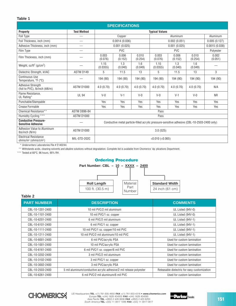
US Headquarters TEL +(1) 781-935-4850 FAX +(1) 781-933-4318 • www.chomerics.comEurope TEL +(44) 1628 404000 FAX +(44) 1628 404090
Asia Pacific TEL +(852) 2 428 8008 FAX +(852) 2 423 8253South America TEL +(55) 11 3917 1099 FAX +(55) 11 3917 0817
* Underwriters Laboratories File # E140244.** Withstands acids, cleaning solvents and alkaline solutions without degradation. Complete list is available from Chomerics’ Ap plications Department.
*** Tested at 60°C, 96 hours, 95% RH.
PART NUMBER DESCRIPTION COMMENTS
CBL-10-1201-2400 10 mil PVC/2 mil aluminum UL Listed (94V-0)
CBL-10-1101-2400 10 mil PVC/1 oz. copper UL Listed (94V-0)
CBL-10-6201-2400 6 mil PVC/2 mil aluminum UL Listed (94V-1)
CBL-10-6101-2400 6 mil PVC/1 oz. copper UL Listed (94V-1)
CBL-10-1111-2400 10 mil PVC/1 oz. copper/10 mil PVC UL Listed (94V-1)
CBL-10-1211-2400 10 mil PVC/2 mil aluminum/10 mil PVC UL Listed (94V-1)
CBL-10-6001-2400 6 mil PVC/acrylic PSA Used for custom lamination
CBL-10-1001-2400 10 mil PVC/acrylic PSA Used for custom lamination
CBL-10-6161-2400 6 mil PVC/1 oz. copper/6 mil PVC Used for custom lamination
CBL-10-3202-2400 3 mil PVC/2 mil aluminum Used for custom lamination
CBL-10-3102-2400 3 mil PVC/1 oz. copper Used for custom lamination
CBL-10-3002-2400 3 mil PVC/acrylic PSA Used for custom lamination
CBL-10-2503-2400 5 mil aluminum/conductive acrylic adhesive/2 mil release polyester Releasable dielectric for easy customization
CBL-10-6261-2400 6 mil PVC/2 mil aluminum/6 mil PVC Used for custom lamination
SPECIFICATIONS
Property Test Method Typical ValuesFoil Type –– Copper Aluminum Aluminum
Foil Thickness, inch (mm) –– 0.0014 (0.036) 0.002 (0.051) 0.005 (0.127)
Adhesive Thickness, inch (mm) –– 0.001 (0.025) 0.001 (0.025) 0.0015 (0.038)
Film Type –– PVC PVC Polyester
Film Thickness, inch (mm) –– 0.003 0.006 0.010 0.003 0.006 0.010 0.002(0.076) (0.152) (0.254) (0.076) (0.152) (0.254) (0.051)
Weight, oz/ft2 (g/cm2) –– 1.15 1.3 1.6 1.15 1.3 1.6 ––(0.0355) (0.040) (0.049) (0.0355) (0.040) (0.049)
Dielectric Strength, kVAC ASTM D149 5 11.5 13 5 11.5 13 3
Continuous Use –– 194 (90) 194 (90) 194 (90) 194 (90) 194 (90) 194 (90) 194 (90)Temperature, °F (°C)
Adhesive Strength ASTM D1000 4.0 (0.70) 4.0 (0.70) 4.0 (0.70) 4.0 (0.70) 4.0 (0.70) 4.0 (0.70) N/A(foil to PVC), lb/inch (kN/m)
Flame Resistance, UL 94 V-0 V-1 V-0 V-0 V-1 V-0 NRUL Rating*
Punchable/Stampable Yes Yes Yes Yes Yes Yes Yes
Crease Formable Yes Yes Yes Yes Yes Yes YesChemical Resistance** ASTM D896-84 PassHumidity Cycling *** ASTM D1000 PassConductive Pressure-Sensitive Adhesive –– Conductive metal particle-filled acrylic pressure-sensitive adhesive (CBL-10-2503-2400 only)
Adhesion Value to Aluminumlbs/inch (N/m) ASTM D1000 3.0 (525)
Electrical Resistanceohms/in2 (ohms/cm2) MIL-STD-202C <0.010 (<0.065)
Ordering ProcedurePart Number: CBL – 10 – XXXX – 2400
Roll Length
100 ft. (30.5 m)
Standard Width
24 inch (61 cm)
MaterialPart
Number
Table 1
Table 2
151
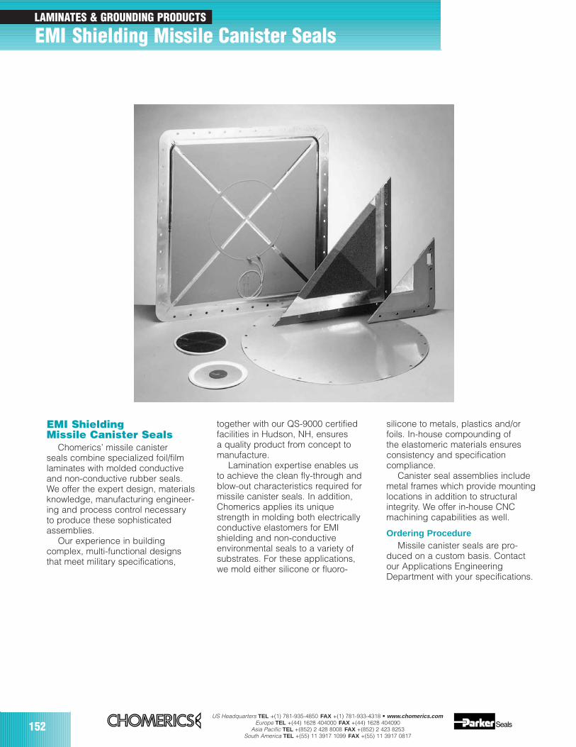
152US Headquarters TEL +(1) 781-935-4850 FAX +(1) 781-933-4318 • www.chomerics.com
Europe TEL +(44) 1628 404000 FAX +(44) 1628 404090Asia Pacific TEL +(852) 2 428 8008 FAX +(852) 2 423 8253
South America TEL +(55) 11 3917 1099 FAX +(55) 11 3917 0817
EMI ShieldingMissile Canister Seals
Chomerics’ missile canisterseals combine specialized foil/filmlaminates with molded conductiveand non-conductive rubber seals.We offer the expert design, materialsknowledge, manufacturing engineer-ing and process control necessaryto produce these sophisticatedassemblies.
Our experience in buildingcomplex, multi-functional designsthat meet military specifications,
together with our QS-9000 certifiedfacilities in Hudson, NH, ensures a quality product from concept tomanufacture.
Lamination expertise enables usto achieve the clean fly-through andblow-out characteristics required formissile canister seals. In addition,Chomerics applies its uniquestrength in molding both electricallyconductive elastomers for EMIshielding and non-conductiveenvironmental seals to a variety ofsubstrates. For these applications,we mold either silicone or fluoro-
silicone to metals, plastics and/orfoils. In-house compounding ofthe elastomeric materials ensuresconsistency and specificationcompliance.
Canister seal assemblies includemetal frames which provide mountinglocations in addition to structuralintegrity. We offer in-house CNCmachining capabilities as well.
Ordering ProcedureMissile canister seals are pro-
duced on a custom basis. Contactour Applications EngineeringDepartment with your specifications.
LAMINATES & GROUNDING PRODUCTS
EMI Shielding Missile Canister Seals
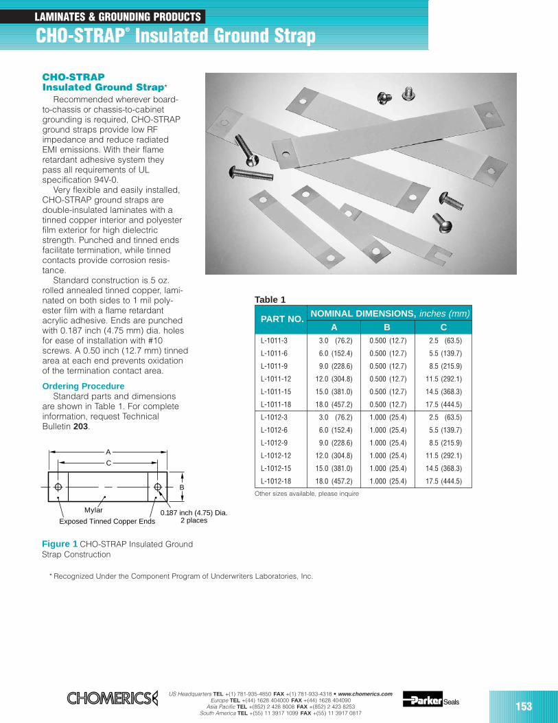
US Headquarters TEL +(1) 781-935-4850 FAX +(1) 781-933-4318 • www.chomerics.comEurope TEL +(44) 1628 404000 FAX +(44) 1628 404090
Asia Pacific TEL +(852) 2 428 8008 FAX +(852) 2 423 8253South America TEL +(55) 11 3917 1099 FAX +(55) 11 3917 0817
153
CHO-STRAPInsulated Ground Strap*
Recommended wherever board-to-chassis or chassis-to-cabinetgrounding is required, CHO-STRAPground straps provide low RFimpedance and reduce radiatedEMI emissions. With their flameretardant adhesive system theypass all requirements of ULspecification 94V-0.
Very flexible and easily installed,CHO-STRAP ground straps aredouble-insulated laminates with atinned copper interior and polyesterfilm exterior for high dielectricstrength. Punched and tinned endsfacilitate termination, while tinnedcontacts provide corrosion resis-tance.
Standard construction is 5 oz.rolled annealed tinned copper, lami-nated on both sides to 1 mil poly-ester film with a flame retardantacrylic adhesive. Ends are punchedwith 0.187 inch (4.75 mm) dia. holesfor ease of installation with #10screws. A 0.50 inch (12.7 mm) tinnedarea at each end prevents oxidationof the termination contact area.
Ordering ProcedureStandard parts and dimensions
are shown in Table 1. For completeinformation, request TechnicalBulletin 203.
* Recognized Under the Component Program of Underwriters Laboratories, Inc.
Table 1
Other sizes available, please inquire
C
A
B
0.187 inch (4.75) Dia.2 placesExposed Tinned Copper Ends
Mylar
Figure 1 CHO-STRAP Insulated Ground Strap Construction
PART NO.NOMINAL DIMENSIONS, inches (mm)
A B CL-1011-3 3.0 (76.2) 0.500 (12.7) 2.5 (63.5)
L-1011-6 6.0 (152.4) 0.500 (12.7) 5.5 (139.7)
L-1011-9 9.0 (228.6) 0.500 (12.7) 8.5 (215.9)
L-1011-12 12.0 (304.8) 0.500 (12.7) 11.5 (292.1)
L-1011-15 15.0 (381.0) 0.500 (12.7) 14.5 (368.3)
L-1011-18 18.0 (457.2) 0.500 (12.7) 17.5 (444.5)
L-1012-3 3.0 (76.2) 1.000 (25.4) 2.5 (63.5)
L-1012-6 6.0 (152.4) 1.000 (25.4) 5.5 (139.7)
L-1012-9 9.0 (228.6) 1.000 (25.4) 8.5 (215.9)
L-1012-12 12.0 (304.8) 1.000 (25.4) 11.5 (292.1)
L-1012-15 15.0 (381.0) 1.000 (25.4) 14.5 (368.3)
L-1012-18 18.0 (457.2) 1.000 (25.4) 17.5 (444.5)
LAMINATES & GROUNDING PRODUCTS
CHO-STRAP® Insulated Ground Strap
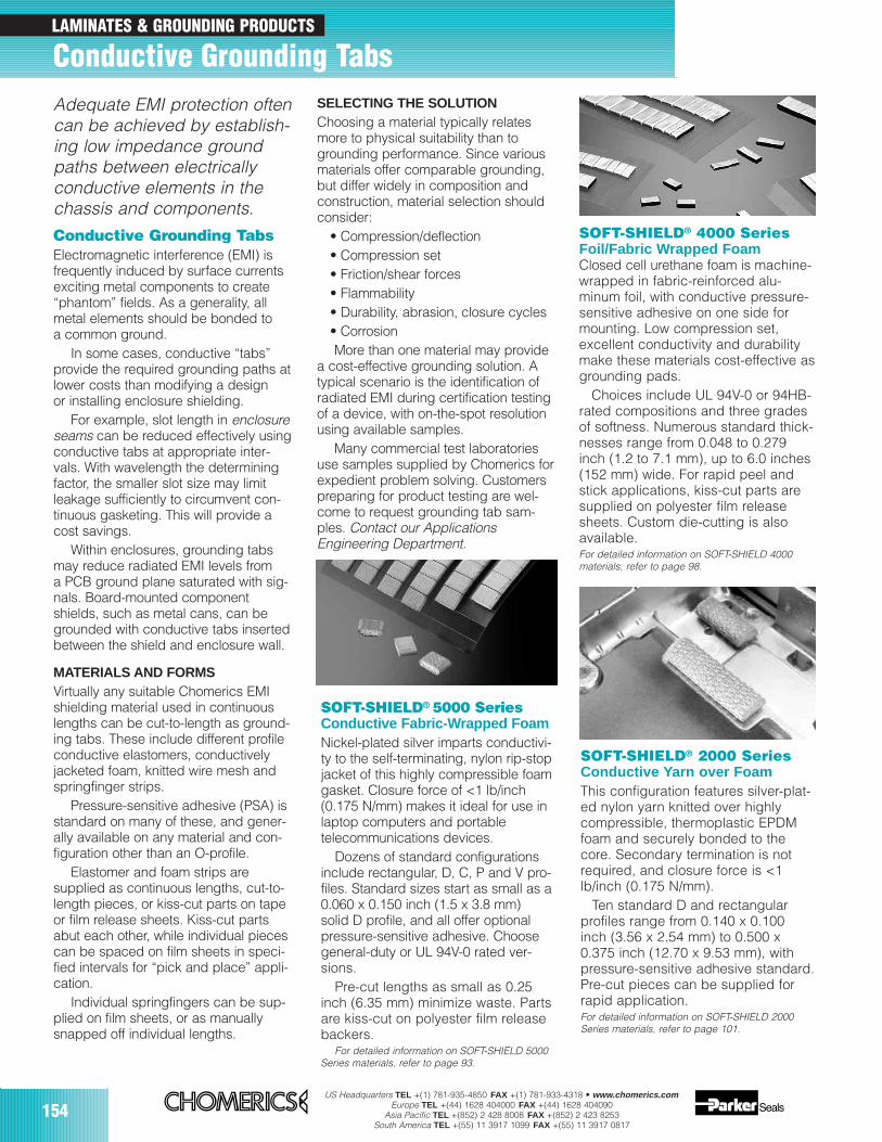
154US Headquarters TEL +(1) 781-935-4850 FAX +(1) 781-933-4318 • www.chomerics.com
Europe TEL +(44) 1628 404000 FAX +(44) 1628 404090Asia Pacific TEL +(852) 2 428 8008 FAX +(852) 2 423 8253
South America TEL +(55) 11 3917 1099 FAX +(55) 11 3917 0817
LAMINATES & GROUNDING PRODUCTS
Conductive Grounding Tabs
Conductive Grounding Tabs Electromagnetic interference (EMI) isfrequently induced by surface currentsexciting metal components to create“phantom” fields. As a generality, allmetal elements should be bonded to a common ground.
In some cases, conductive “tabs”provide the required grounding paths atlower costs than modifying a design or installing enclosure shielding.
For example, slot length in enclosureseams can be reduced effectively usingconductive tabs at appropriate inter-vals. With wavelength the determiningfactor, the smaller slot size may limitleakage sufficiently to circumvent con-tinuous gasketing. This will provide acost savings.
Within enclosures, grounding tabsmay reduce radiated EMI levels from a PCB ground plane saturated with sig-nals. Board-mounted componentshields, such as metal cans, can begrounded with conductive tabs insertedbetween the shield and enclosure wall.
MATERIALS AND FORMSVirtually any suitable Chomerics EMIshielding material used in continuouslengths can be cut-to-length as ground-ing tabs. These include different profileconductive elastomers, conductivelyjacketed foam, knitted wire mesh andspringfinger strips.
Pressure-sensitive adhesive (PSA) isstandard on many of these, and gener-ally available on any material and con-figuration other than an O-profile.
Elastomer and foam strips are supplied as continuous lengths, cut-to-length pieces, or kiss-cut parts on tapeor film release sheets. Kiss-cut partsabut each other, while individual piecescan be spaced on film sheets in speci-fied intervals for “pick and place” appli-cation.
Individual springfingers can be sup-plied on film sheets, or as manuallysnapped off individual lengths.
SELECTING THE SOLUTIONChoosing a material typically relatesmore to physical suitability than togrounding performance. Since variousmaterials offer comparable grounding,but differ widely in composition andconstruction, material selection shouldconsider:
• Compression/deflection• Compression set• Friction/shear forces• Flammability• Durability, abrasion, closure cycles• Corrosion More than one material may provide
a cost-effective grounding solution. Atypical scenario is the identification ofradiated EMI during certification testingof a device, with on-the-spot resolutionusing available samples.
Many commercial test laboratoriesuse samples supplied by Chomerics forexpedient problem solving. Customerspreparing for product testing are wel-come to request grounding tab sam-ples. Contact our ApplicationsEngineering Department.
Adequate EMI protection oftencan be achieved by establish-ing low impedance groundpaths between electricallyconductive elements in thechassis and components.
SOFT-SHIELD® 5000 SeriesConductive Fabric-Wrapped Foam Nickel-plated silver imparts conductivi-ty to the self-terminating, nylon rip-stopjacket of this highly compressible foamgasket. Closure force of <1 lb/inch(0.175 N/mm) makes it ideal for use inlaptop computers and portabletelecommunications devices.
Dozens of standard configurationsinclude rectangular, D, C, P and V pro-files. Standard sizes start as small as a0.060 x 0.150 inch (1.5 x 3.8 mm)solid D profile, and all offer optionalpressure-sensitive adhesive. Choosegeneral-duty or UL 94V-0 rated ver-sions.
Pre-cut lengths as small as 0.25inch (6.35 mm) minimize waste. Partsare kiss-cut on polyester film releasebackers.
For detailed information on SOFT-SHIELD 5000Series materials, refer to page 93.
SOFT-SHIELD® 4000 SeriesFoil/Fabric Wrapped FoamClosed cell urethane foam is machine-wrapped in fabric-reinforced alu-minum foil, with conductive pressure-sensitive adhesive on one side formounting. Low compression set,excellent conductivity and durabilitymake these materials cost-effective asgrounding pads.
Choices include UL 94V-0 or 94HB-rated compositions and three gradesof softness. Numerous standard thick-nesses range from 0.048 to 0.279inch (1.2 to 7.1 mm), up to 6.0 inches(152 mm) wide. For rapid peel andstick applications, kiss-cut parts aresupplied on polyester film releasesheets. Custom die-cutting is alsoavailable. For detailed information on SOFT-SHIELD 4000materials, refer to page 98.
SOFT-SHIELD® 2000 SeriesConductive Yarn over Foam This configuration features silver-plat-ed nylon yarn knitted over highlycompressible, thermoplastic EPDMfoam and securely bonded to thecore. Secondary termination is notrequired, and closure force is <1lb/inch (0.175 N/mm).
Ten standard D and rectangular profiles range from 0.140 x 0.100 inch (3.56 x 2.54 mm) to 0.500 x0.375 inch (12.70 x 9.53 mm), withpressure-sensitive adhesive standard. Pre-cut pieces can be supplied forrapid application.For detailed information on SOFT-SHIELD 2000Series materials, refer to page 101.
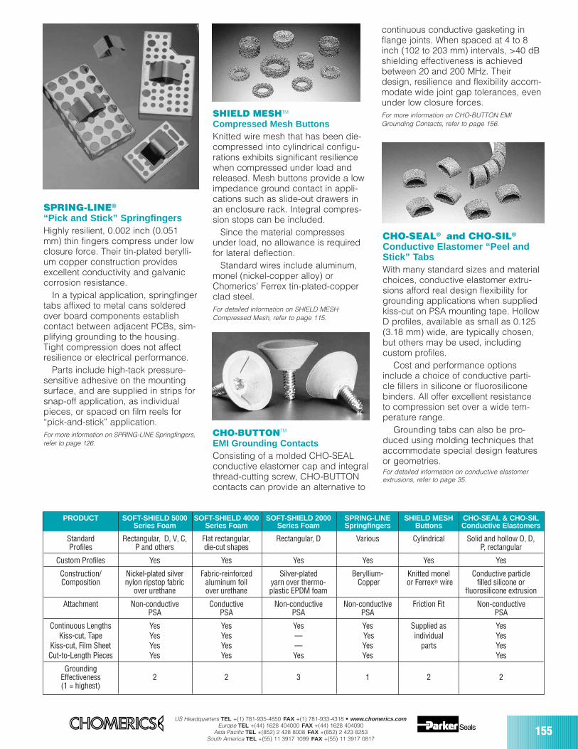
US Headquarters TEL +(1) 781-935-4850 FAX +(1) 781-933-4318 • www.chomerics.comEurope TEL +(44) 1628 404000 FAX +(44) 1628 404090
Asia Pacific TEL +(852) 2 428 8008 FAX +(852) 2 423 8253South America TEL +(55) 11 3917 1099 FAX +(55) 11 3917 0817
155
PRODUCT SOFT-SHIELD 5000 SOFT-SHIELD 4000 SOFT-SHIELD 2000 SPRING-LINE SHIELD MESH CHO-SEAL & CHO-SILSeries Foam Series Foam Series Foam Springfingers Buttons Conductive Elastomers
Standard Rectangular, D, V, C, Flat rectangular, Rectangular, D Various Cylindrical Solid and hollow O, D, Profiles P and others die-cut shapes P, rectangular
Custom Profiles Yes Yes Yes Yes Yes Yes
Construction/ Nickel-plated silver Fabric-reinforced Silver-plated Beryllium- Knitted monel Conductive particleComposition nylon ripstop fabric aluminum foil yarn over thermo- Copper or Ferrex® wire filled silicone or
over urethane over urethane plastic EPDM foam fluorosilicone extrusion
Attachment Non-conductive Conductive Non-conductive Non-conductive Friction Fit Non-conductive PSA PSA PSA PSA PSA
Continuous Lengths Yes Yes Yes Yes Supplied as YesKiss-cut, Tape Yes Yes — Yes individual Yes
Kiss-cut, Film Sheet Yes Yes — Yes parts YesCut-to-Length Pieces Yes Yes Yes Yes Yes
GroundingEffectiveness 2 2 3 1 2 2(1 = highest)
CHO-BUTTONTM
EMI Grounding ContactsConsisting of a molded CHO-SEAL conductive elastomer cap and integralthread-cutting screw, CHO-BUTTONcontacts can provide an alternative to
SHIELD MESHTM
Compressed Mesh ButtonsKnitted wire mesh that has been die-compressed into cylindrical configu-rations exhibits significant resiliencewhen compressed under load andreleased. Mesh buttons provide a lowimpedance ground contact in appli-cations such as slide-out drawers inan enclosure rack. Integral compres-sion stops can be included.
Since the material compressesunder load, no allowance is requiredfor lateral deflection.
Standard wires include aluminum,monel (nickel-copper alloy) orChomerics’ Ferrex tin-plated-copperclad steel.For detailed information on SHIELD MESHCompressed Mesh, refer to page 115.
SPRING-LINE®
“Pick and Stick” Springfingers Highly resilient, 0.002 inch (0.051mm) thin fingers compress under lowclosure force. Their tin-plated berylli-um copper construction providesexcellent conductivity and galvaniccorrosion resistance.
In a typical application, springfingertabs affixed to metal cans solderedover board components establishcontact between adjacent PCBs, sim-plifying grounding to the housing.Tight compression does not affectresilience or electrical performance.
Parts include high-tack pressure-sensitive adhesive on the mountingsurface, and are supplied in strips forsnap-off application, as individualpieces, or spaced on film reels for“pick-and-stick” application.For more information on SPRING-LINE Springfingers,refer to page 126.
CHO-SEAL® and CHO-SIL®
Conductive Elastomer “Peel andStick” TabsWith many standard sizes and materialchoices, conductive elastomer extru-sions afford real design flexibility forgrounding applications when suppliedkiss-cut on PSA mounting tape. HollowD profiles, available as small as 0.125(3.18 mm) wide, are typically chosen,but others may be used, includingcustom profiles.
Cost and performance optionsinclude a choice of conductive parti-cle fillers in silicone or fluorosiliconebinders. All offer excellent resistanceto compression set over a wide tem-perature range.
Grounding tabs can also be pro-duced using molding techniques thataccommodate special design featuresor geometries.For detailed information on conductive elastomerextrusions, refer to page 35.
continuous conductive gasketing inflange joints. When spaced at 4 to 8inch (102 to 203 mm) intervals, >40 dBshielding effectiveness is achievedbetween 20 and 200 MHz. Theirdesign, resilience and flexibility accom-modate wide joint gap tolerances, evenunder low closure forces.For more information on CHO-BUTTON EMIGrounding Contacts, refer to page 156.
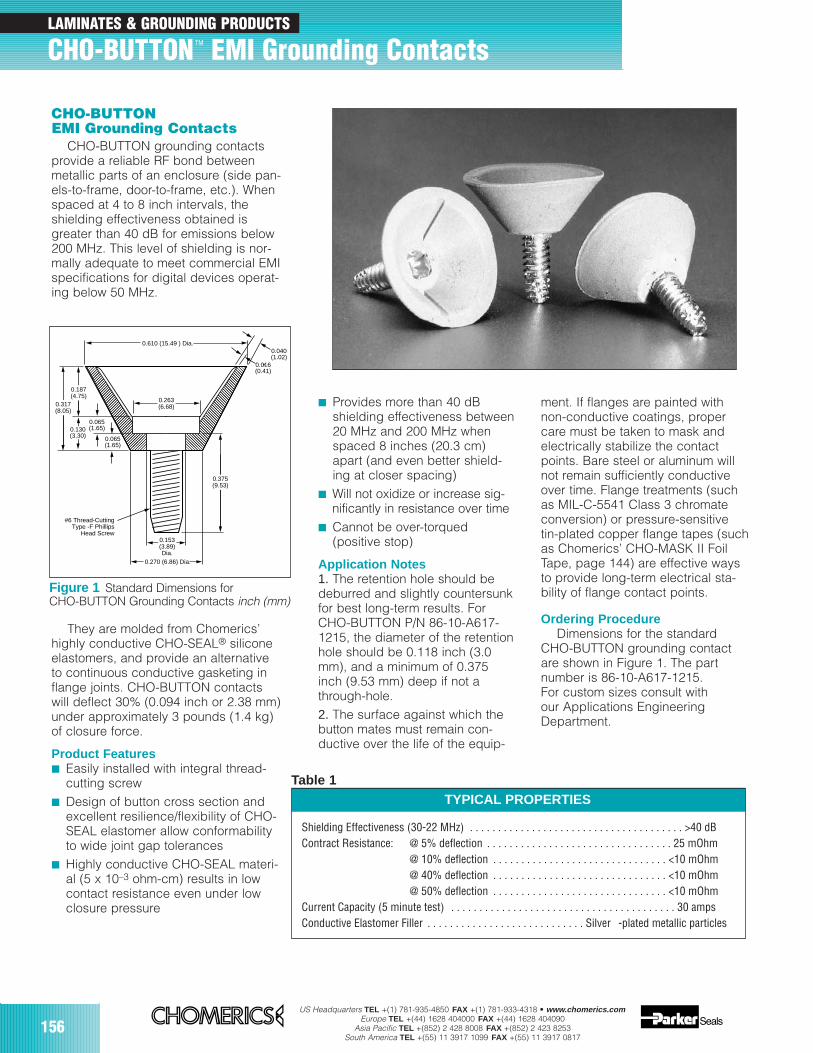
156US Headquarters TEL +(1) 781-935-4850 FAX +(1) 781-933-4318 • www.chomerics.com
Europe TEL +(44) 1628 404000 FAX +(44) 1628 404090Asia Pacific TEL +(852) 2 428 8008 FAX +(852) 2 423 8253
South America TEL +(55) 11 3917 1099 FAX +(55) 11 3917 0817
CHO-BUTTONEMI Grounding Contacts
CHO-BUTTON grounding contactsprovide a reliable RF bond betweenmetallic parts of an enclosure (side pan-els-to-frame, door-to-frame, etc.). Whenspaced at 4 to 8 inch intervals, theshielding effectiveness obtained isgreater than 40 dB for emissions below200 MHz. This level of shielding is nor-mally adequate to meet commercial EMIspecifications for digital devices operat-ing below 50 MHz.
They are molded from Chomerics’highly conductive CHO-SEAL® siliconeelastomers, and provide an alternativeto continuous conductive gasketing inflange joints. CHO-BUTTON contactswill deflect 30% (0.094 inch or 2.38 mm)under approximately 3 pounds (1.4 kg)of closure force.
Product Features Easily installed with integral thread-
cutting screw Design of button cross section and
excellent resilience/flexibility of CHO-SEAL elastomer allow conformabilityto wide joint gap tolerances
Highly conductive CHO-SEAL materi-al (5 x 10⁻³ ohm-cm) results in lowcontact resistance even under lowclosure pressure
Provides more than 40 dBshielding effectiveness between20 MHz and 200 MHz whenspaced 8 inches (20.3 cm)apart (and even better shield-ing at closer spacing)
Will not oxidize or increase sig-nificantly in resistance over time
Cannot be over-torqued(positive stop)
Application Notes1. The retention hole should bedeburred and slightly countersunkfor best long-term results. ForCHO-BUTTON P/N 86-10-A617-1215, the diameter of the retentionhole should be 0.118 inch (3.0mm), and a minimum of 0.375inch (9.53 mm) deep if not athrough-hole. 2. The surface against which thebutton mates must remain con-ductive over the life of the equip-
ment. If flanges are painted withnon-conductive coatings, propercare must be taken to mask andelectrically stabilize the contactpoints. Bare steel or aluminum willnot remain sufficiently conductiveover time. Flange treatments (suchas MIL-C-5541 Class 3 chromateconversion) or pressure-sensitivetin-plated copper flange tapes (suchas Chomerics’ CHO-MASK II FoilTape, page 144) are effective waysto provide long-term electrical sta-bility of flange contact points.
Ordering ProcedureDimensions for the standard
CHO-BUTTON grounding contactare shown in Figure 1. The part number is 86-10-A617-1215. For custom sizes consult with our Applications EngineeringDepartment.
Table 1
0.375(9.53)
0.263(6.68)
0.187(4.75)
0.317(8.05)
0.130(3.30) 0.065
(1.65)
0.040(1.02)
0.016(0.41)
0.065(1.65)
0.153(3.89)Dia.
0.270 (6.86) Dia.
0.610 (15.49 ) Dia.
#6 Thread-CuttingType -F Phillips
Head Screw
Figure 1 Standard Dimensions forCHO-BUTTON Grounding Contacts inch (mm)
Shielding Effectiveness (30-22 MHz) . . . . . . . . . . . . . . . . . . . . . . . . . . . . . . . . . . . . . . >40 dBContract Resistance: @ 5% deflection . . . . . . . . . . . . . . . . . . . . . . . . . . . . . . . . . 25 mOhm
@ 10% deflection . . . . . . . . . . . . . . . . . . . . . . . . . . . . . . . <10 mOhm@ 40% deflection . . . . . . . . . . . . . . . . . . . . . . . . . . . . . . . <10 mOhm@ 50% deflection . . . . . . . . . . . . . . . . . . . . . . . . . . . . . . . <10 mOhm
Current Capacity (5 minute test) . . . . . . . . . . . . . . . . . . . . . . . . . . . . . . . . . . . . . . . . 30 ampsConductive Elastomer Filler . . . . . . . . . . . . . . . . . . . . . . . . . . . . Silver -plated metallic particles
TYPICAL PROPERTIES
LAMINATES & GROUNDING PRODUCTS
CHO-BUTTON TM EMI Grounding Contacts
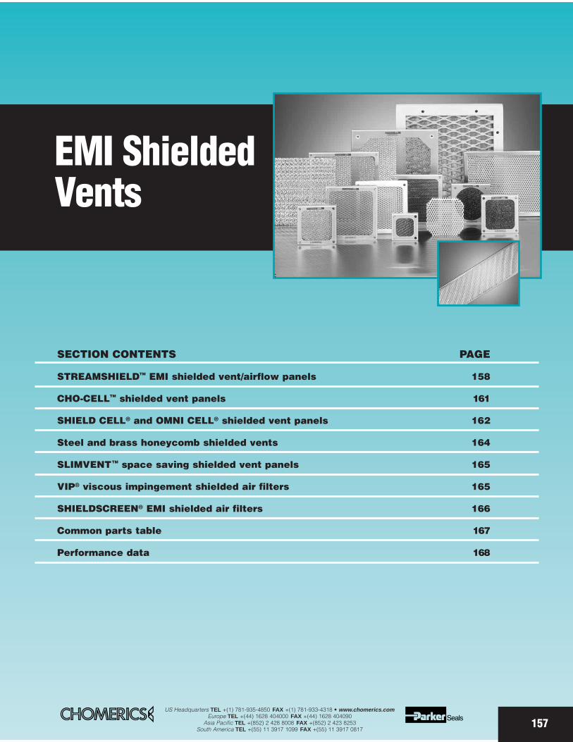
SECTION CONTENTS PAGE
STREAMSHIELDTM EMI shielded vent/airflow panels 158
CHO-CELLTM shielded vent panels 161
SHIELD CELL® and OMNI CELL® shielded vent panels 162
Steel and brass honeycomb shielded vents 164
SLIMVENTTM space saving shielded vent panels 165
VIP® viscous impingement shielded air filters 165
SHIELDSCREEN® EMI shielded air filters 166
Common parts table 167
Performance data 168
EMI ShieldedVents
157US Headquarters TEL +(1) 781-935-4850 FAX +(1) 781-933-4318 • www.chomerics.com
Europe TEL +(44) 1628 404000 FAX +(44) 1628 404090Asia Pacific TEL +(852) 2 428 8008 FAX +(852) 2 423 8253
South America TEL +(55) 11 3917 1099 FAX +(55) 11 3917 0817

158US Headquarters TEL +(1) 781-935-4850 FAX +(1) 781-933-4318 • www.chomerics.com
Europe TEL +(44) 1628 404000 FAX +(44) 1628 404090Asia Pacific TEL +(852) 2 428 8008 FAX +(852) 2 423 8253
South America TEL +(55) 11 3917 1099 FAX +(55) 11 3917 0817
EMI SHIELDED VENTS
STREAMSHIELD™ Technology Driven EMI/Airflow Solution
Lightweight design
Economical construction
Excellent shielding performance (>50 dB @ 10 GHz)
Excellent dimensional aspect ratios for airflow - ≥95% open area honeycomb for maximum airflow
Customization
Rapid prototyping
STREAMSHIELD EMI Shielded Vent/Airflow PanelsWith their exclusive designs (patent pending) and manufacturingprocess, Chomerics’ STREAMSHIELD vent panels have been developed as a high performance, economical solution to the EMI andairflow issues in information technology and telecommunications applica-tions. Increased electromagnetic radiation and heat generation, togetherwith intensified regulatory requirements for emissions suppression,necessitate a more sophisticated solution than simple perforations or louvers in electronic enclosures.
STREAMSHIELD vent panels deliver EMC and thermal management performance that meets the technology demands of today’s electronic systems, including:
SwitchesHigh speed routersTest equipmentCooling fan coversIndoor cellular base stationsWireless and wireline infrastructures
Personal computersNetwork serversNetwork cabinets and enclosuresAccess equipmentRack mounted power amplifiersStorage cabinets
Construction Choices STREAMSHIELD vent panels are pro-duced in two styles. In the first style,the honeycomb is incorporated into astamped “tray” with integral tangs(fingers) around the periphery. Thespecial mechanical process used tobend the tangs into the honeycombensures secure, consistent and reli-able honeycomb-frame contact (seephoto and Figure 2). This style isoffered in two standard configurationsthat provide a square fan opening, ora round fan opening, as shown inFigure 3. In the second style, thehoneycomb is incorporated into a roll-formed frame with a knitted aluminumwire mesh that maximizes contact
(minimizes impedance) betweenthe honeycomb and frame. Otherconstruction features include:
The STREAMSHIELD designs provide the same high performance as tradi-tional honeycomb vent panels. Their honeycomb is ≥95% open area, minimiz-ing pressure drop (Figure 4). The aperture size and cell depth provides thewaveguide absorption and cut-off frequencies needed to solve even the mostdifficult EMI and airflow challenges.
MHz
Att
enu
atio
n (
dB
)
100
90
80
70
60
50
40
30
20
10
10 100 1,000 10,0000
Typical Part Dimension: 12x12 inch (305 x 305 mm) overall with 9/16 inch (14 mm) frame
Optional OMNI CELL® honeycombconstruction (oriented 90° to counter-act polarization effects)OMNI CELL honeycomb constructionprovides higher shielding effective-ness than standard honeycomb construction. Contained in the samestandard thickness frame, it utilizestwo honeycomb panels, each of whichis half the thickness of standard hon-eycomb. Foil directions of the twoOMNI CELL layers are at right anglesto each other to eliminate the polar-ized shielding characteristics of conventional honeycomb. Refer to Figure 2.
• Aluminum alloy 3003 or 5052 framing
• Aluminum alloy 5052 honey-comb, 1/16 (1.6 mm) or 1/8 inch (3.2 mm) cells —1/8 inch (3.2 mm), 1/4 inch (6.35 mm) or 1/2 inch (12.7 mm) thickness
• 6.1 lb./ft.3 density, 0.0015 inch (0.38 mm) thick foil
• SOFT-SHIELD 5000 EMI Gasket (see page 93 for detailed description)
• Choice of surface finishes
Figure 1 Shielding Effectiveness (dB) ofSTREAMSHIELD Vent Panel with OMNI CELLConstruction

US Headquarters TEL +(1) 781-935-4850 FAX +(1) 781-933-4318 • www.chomerics.comEurope TEL +(44) 1628 404000 FAX +(44) 1628 404090
Asia Pacific TEL +(852) 2 428 8008 FAX +(852) 2 423 8253South America TEL +(55) 11 3917 1099 FAX +(55) 11 3917 0817 159
2 Layers of aluminum honeycomb
SOFTSHIELD 5000 gasket
Gasket die-cutaround hole
"Tangs" provide positive contactbetween honeycomb and frame
Nickel or tin plating or conductive coating (option)
Self-clinching nut (option)
Self-clinching standoffshown as compression stop (option)
OMNI CELL Honeycomb Standard Honeycomb
Customization Options• Alternative honeycomb cell sizes and
thicknesses • Alternative EMI gaskets• Custom sized frames• Custom fastener hole patterns• Chromate conversion coating —
clear or yellow, provides corrosion resistance and paintable surface
• Electroless nickel or electrolytic tin plating — enhances EMI shielding and corrosion protection, but chro-mate conversion coating also required if parts are to be painted
• Conductive paint - alternative to plating
• Intumescent paint - see inset below.• Foam filters - 30 pore per inch poly-
ether filter foam, UL94 HF1 rated. Other pore densities are available.
Optional surface treatment forSTREAMSHIELD panels or otherhoneycomb products
Chomerics’ HEICF 1594 intu-mescent coating is a water-basedsystem that is applied to honey-comb shielding vent panels toimprove fire containment in elec-tronic enclosures. A thin coating inthe honeycomb cells reacts onexposure to flame or heat at 300°F(149°C) and expands rapidly, fill-ing the cells with a carbonaceousfoam that prevents flames frompropagating through the honey-comb. This system can be invalu-able in meeting the requirementsfor Network Equipment BuildingSystems (NEBS) compliance, andBellcore GR-63-CORE PhysicalProtection Standards for FireResistance (Spread).Fire Protection PerformanceThe HEICF 1594 coating system isbased on the same fire retardantchemistry that meets the require-ments of the ASTM E-84 TestProcedure and that is classified byUL as providing Class A (0-25)flame spread protection and lowsmoke density (15 on a scale of 0-450) on the standard test sub-strate. Currently, there are no
• Protective grilles - 0.030 inch (0.76 mm) thick, 0.250 inch (6.35 mm) hex perforated metal with 0.281 inch (7.14 mm) centers, for harsh environments
• Special hardware - for example, self-clinching standoffs or nuts (Figure 2)
Chomerics’ Application EngineeringDepartment is ready to assist you with evalu-ating cost-effective STREAMSHIELD EMIshielded vent/airflow panels in your design.
Coated (right) and non-coated (left)STREAMSHIELD vent panels.Intumescent coating of plain honeycombpane (unframed) is also available.
Figure 2 STREAMSHIELD Panel Construction (stamped tray) Example
established test criteria for intu-mescent coatings on honeycombvent panels. NOTE: Suitability ofuse for this product in a specificapplication must be determined bythe user.Heat and Humidity ResistanceThe HEICF 1594 coating systemhas been tested for heat andhumidity aging in Chomerics’ labo-ratories. Heat aging at 185°F(85°C) for 168 hours caused slightdarkening of the coating, but hadno effect on the intumescent prop-erties. Humidity aging at 185°F(85°C) and 85% relative humidityfor 168 hours also had no effect onthe intumescent properties of thecoating system.Mechanical ConsiderationsThere is a reduction in the openarea of the honeycomb when thecoating system is applied. Thecoating system has approximately4 mils (0.10 mm) dry film thickness.Standard 6.1 lb./ft3, 1/8 inch cell(3.18 mm) honeycomb is 96%open before coating. After coating,it is 84% open. The addition of thecoating increases the structuralstrength/stiffness of the honey-comb.
ColorsThe HEICF 1594 coating system is off-white in color as a standard, but is com-patible with universal colorants withinlimits. Many colors, therefore, can beoffered on a custom option basis.
In addition to coating EMI shieldedvents, Chomerics extends itsIntumescent Coating capabilities tounframed honeycomb paneling. ContactChomerics for more information.
Fire Retardant HEICF 1594 Intumescent Coating System
P.O.
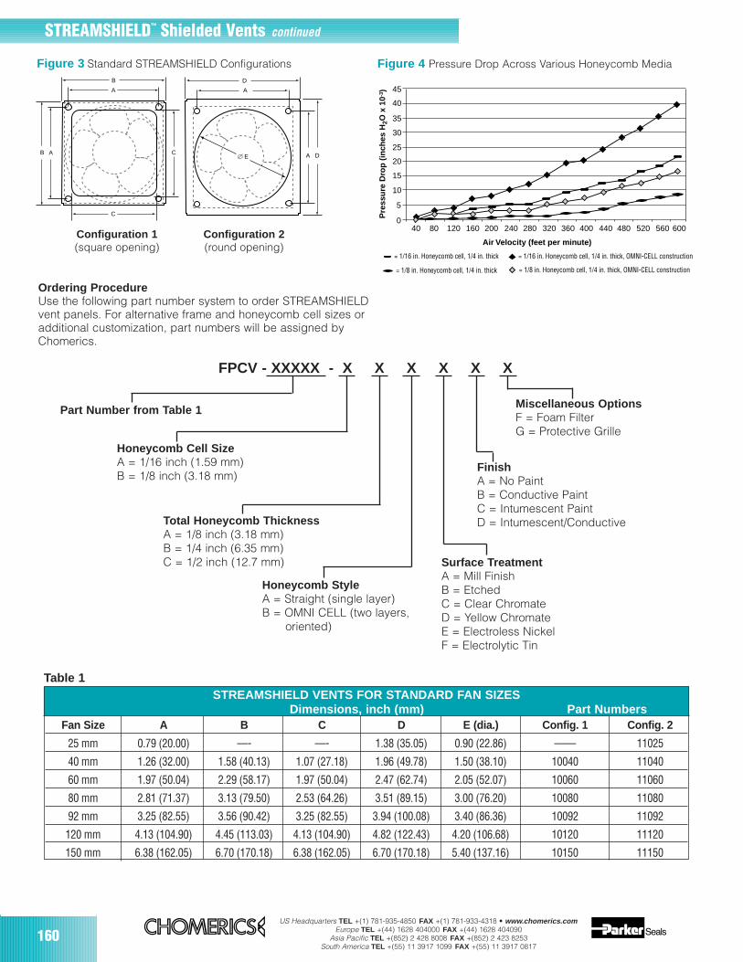
160US Headquarters TEL +(1) 781-935-4850 FAX +(1) 781-933-4318 • www.chomerics.com
Europe TEL +(44) 1628 404000 FAX +(44) 1628 404090Asia Pacific TEL +(852) 2 428 8008 FAX +(852) 2 423 8253
South America TEL +(55) 11 3917 1099 FAX +(55) 11 3917 0817
STREAMSHIELD VENTS FOR STANDARD FAN SIZES
STREAMSHIELD™ Shielded Vents continued
Fan Size A B C D E (dia.) Config. 1 Config. 2
25 mm 0.79 (20.00) —- —- 1.38 (35.05) 0.90 (22.86) —— 11025
40 mm 1.26 (32.00) 1.58 (40.13) 1.07 (27.18) 1.96 (49.78) 1.50 (38.10) 10040 11040
60 mm 1.97 (50.04) 2.29 (58.17) 1.97 (50.04) 2.47 (62.74) 2.05 (52.07) 10060 11060
80 mm 2.81 (71.37) 3.13 (79.50) 2.53 (64.26) 3.51 (89.15) 3.00 (76.20) 10080 11080
92 mm 3.25 (82.55) 3.56 (90.42) 3.25 (82.55) 3.94 (100.08) 3.40 (86.36) 10092 11092
120 mm 4.13 (104.90) 4.45 (113.03) 4.13 (104.90) 4.82 (122.43) 4.20 (106.68) 10120 11120
150 mm 6.38 (162.05) 6.70 (170.18) 6.38 (162.05) 6.70 (170.18) 5.40 (137.16) 10150 11150
A
AB
B D
A
C
C A DE
Figure 3 Standard STREAMSHIELD Configurations
45
40
40 120 160 200 240 280 320 360 400 440 480 520 560 60080
35
30
25
20
15
10
5
0
Air Velocity (feet per minute)
Pre
ssu
re D
rop
(in
ches
H2O
x 1
0-3 )
= 1/16 in. Honeycomb cell, 1/4 in. thick = 1/16 in. Honeycomb cell, 1/4 in. thick, OMNI-CELL construction
= 1/8 in. Honeycomb cell, 1/4 in. thick, OMNI-CELL construction = 1/8 in. Honeycomb cell, 1/4 in. thick
Figure 4 Pressure Drop Across Various Honeycomb Media
Ordering ProcedureUse the following part number system to order STREAMSHIELDvent panels. For alternative frame and honeycomb cell sizes oradditional customization, part numbers will be assigned byChomerics.
FPCV - XXXXX - X X X X X X
Part Number from Table 1
Honeycomb Cell SizeA = 1/16 inch (1.59 mm)B = 1/8 inch (3.18 mm)
Total Honeycomb ThicknessA = 1/8 inch (3.18 mm)B = 1/4 inch (6.35 mm)C = 1/2 inch (12.7 mm)
Miscellaneous OptionsF = Foam FilterG = Protective Grille
FinishA = No PaintB = Conductive PaintC = Intumescent PaintD = Intumescent/Conductive
Honeycomb StyleA = Straight (single layer)B = OMNI CELL (two layers,
oriented)
Surface TreatmentA = Mill FinishB = EtchedC = Clear ChromateD = Yellow ChromateE = Electroless NickelF = Electrolytic Tin
Table 1
Configuration 1(square opening)
Configuration 2(round opening)
Dimensions, inch (mm) Part Numbers
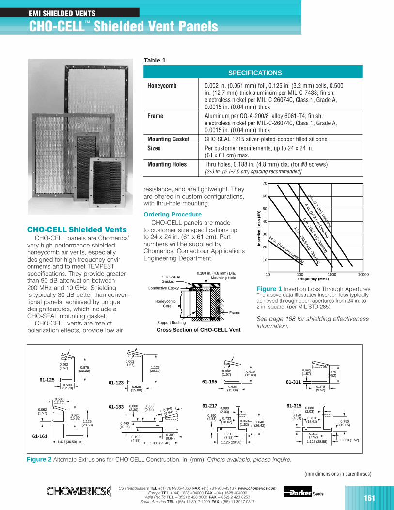
US Headquarters TEL +(1) 781-935-4850 FAX +(1) 781-933-4318 • www.chomerics.comEurope TEL +(44) 1628 404000 FAX +(44) 1628 404090
Asia Pacific TEL +(852) 2 428 8008 FAX +(852) 2 423 8253South America TEL +(55) 11 3917 1099 FAX +(55) 11 3917 0817 161
CHO-CELL Shielded VentsCHO-CELL panels are Chomerics’
very high performance shieldedhoneycomb air vents, especiallydesigned for high frequency envir-onments and to meet TEMPESTspecifications. They provide greaterthan 90 dB attenuation between200 MHz and 10 GHz. Shieldingis typically 30 dB better than conven-tional panels, achieved by uniquedesign features, which include aCHO-SEAL mounting gasket.
CHO-CELL vents are free ofpolarization effects, provide low air
Figure 1 Insertion Loss Through AperturesThe above data illustrates insertion loss typicallyachieved through open apertures from 24 in. to2 in. square (per MIL-STD-285).
SPECIFICATIONS
Honeycomb 0.002 in. (0.051 mm) foil, 0.125 in. (3.2 mm) cells, 0.500 in. (12.7 mm) thick aluminum per MIL-C-7438; finish:electroless nickel per MIL-C-26074C, Class 1, Grade A,0.0015 in. (0.04 mm) thick
Frame Aluminum per QQ-A-200/8 alloy 6061-T4; finish:electroless nickel per MIL-C-26074C, Class 1, Grade A,0.0015 in. (0.04 mm) thick
Mounting Gasket CHO-SEAL 1215 silver-plated-copper filled siliconeSizes Per customer requirements, up to 24 x 24 in.
(61 x 61 cm) max.Mounting Holes Thru holes, 0.188 in. (4.8 mm) dia. (for #8 screws)
[2-3 in. (5.1-7.6 cm) spacing recommended]
CHO-SEALGasket
Conductive Epoxy
HoneycombCore
Support Bushing
Frame
0.188 in. (4.8 mm) Dia.Mounting Hole
Cross Section of CHO-CELL Vent
resistance, and are lightweight. Theyare offered in custom configurations,with thru-hole mounting.
Ordering ProcedureCHO-CELL panels are made
to customer size specifications upto 24 x 24 in. (61 x 61 cm). Partnumbers will be supplied byChomerics. Contact our ApplicationsEngineering Department.
0.062(1.57)
1.125(28.58)
0.625(15.88)
0.062(1.57)
0.500(12.70)
1.125(28.58)
0.625(15.88)
1.437(36.50)
0.062(1.57)
0.625(15.88)
0.625(15.88)
0.375(9.52)
0.500(12.70)
0.875(22.22)
0.062(1.57)
0.062(1.57)
0.375(9.52)
0.312(7.92)
0.060 (1.52)
0.080(2.03)
0.190(4.83)
1.040(26.42)
1.125 (28.58)
0.733(18.62)
1.125 (28.58)
0.312(7.92)
0.060 (1.52)
0.080(2.03)
0.190(4.83)
0.750(19.05)
0.733(18.62)
0.380(9.64)
0.380
(9.64)
1.000 (25.40)
0.400(10.16)
0.192(4.88)
0.080(2.30)
0.380(9.64)
61-125 61-123 61-195 61-311
61-31561-21761-183
61-161
Figure 2 Alternate Extrusions for CHO-CELL Construction, in. (mm). Others available, please inquire.
10
10
100 1000 10000
20
30
40
50
60
70
Frequency (MHz)
Inse
rtio
n L
oss
(d
B)
2 in. (5.1 cm) O
pening
4 in. (10.2 cm) O
pening
6 in. (15.2 cm) O
pening
12 in. (30.5 cm) O
pening
24 in. (61.0 cm) Opening
EMI SHIELDED VENTS
CHO-CELL™ Shielded Vent Panels
Table 1
See page 168 for shielding effectivenessinformation.
(mm dimensions in parentheses)

US Headquarters TEL +(1) 781-935-4850 FAX +(1) 781-933-4318 • www.chomerics.comEurope TEL +(44) 1628 404000 FAX +(44) 1628 404090
Asia Pacific TEL +(852) 2 428 8008 FAX +(852) 2 423 8253South America TEL +(55) 11 3917 1099 FAX +(55) 11 3917 0817
162
SHIELD CELLand OMNI CELLEMI Shielded Ventilating Panels
Ready-to-install SHIELD CELL andOMNI CELL panels provide maximumEMI shielding with minimum pressuredrop (air flow resistance) for ventilatingair. All styles are composed of metalhoneycomb shielding panels in EMIgasketed frames of like material.Panels are ready-to-mount, in sucha manner that the frame gasketingis compressed firmly against theshielded housing to maximizeshielding performance.
Standard framing for all paneldesigns includes both an EMIshielding gasket and a seal, from acombination of monel knitted wiremesh and sponge neoprene. Panelslarger than 12 x 24 in. (305 x 610 mm)are equipped with cross braces.
SHIELD CELL PanelsStandard SHIELD CELL panel
construction is all-aluminum,with 1/8 in. (3.2 mm) cells, 1/2 in.
(12.7 mm) thick. The complete frame/honeycomb assemblies are chromateconversion coated. Additional sizesavailable include: 3/16 in. (4.7 mm)cells, 3/4 in. (19 mm) thick; and1/4 in. (6.4 mm) cells, 1 in. (25.4 mm)thick. Standard aluminum honeycombis recommended for applicationswhere shielding requirements arenot severe.*
For improved shielding effective-ness and environmental protection,these lightweight aluminum ventilationpanels are available tin plated.However, in applications requiringmaximum shielding levels andgreater weight support, either steelor brass honeycomb shielded ventsare recommended. (Refer to page164, Steel and Brass HoneycombShielded Vents, for specifications.)
OMNI CELL PanelsOMNI CELL ventilating panels are
high performance aluminum honey-comb units in Chomerics’ uniqueconfiguration. The OMNI CELL
configuration eliminates the normalpolarized shielding characteristics ofconventional aluminum honeycomb,as do brass and steel panels. Inplace of the single honeycomb, twoparallel honeycomb panels, eachhalf the thickness of standardSHIELD CELL honeycomb, arecontained in a single frame ofstandard thickness. Foil directionsof the two honeycomb layers areat right angles to each other toeliminate non-symmetrical shieldingeffects. Each honeycomb layercontains 1/8 in. (3.2 mm) cells, 1/4 in. (6.4 mm) thick, for a totalthickness of 1/2 in. (12.7 mm). Thefinished panel assemblies are chromate conversion coated.
OMNI CELL construction is usuallythe best general purpose honey-comb vent. It provides significantlymore shielding than conventionalSHIELD CELL aluminum honeycomb,at only nominally higher cost.
Drip Proof OMNI CELL PanelsIn this construction, the outer
layer of aluminum honeycomb isslanted down and out at 30°, 45°, or 60° from the horizontal. Thisdrip-proof construction results ina somewhat increased air flowresistance (Figure 4).
Figure 1 OMNI CELL HoneycombConstruction
**See page 168 for shielding performance data.
(mm dimensions in parentheses)
Foil Direction ofUpper Honeycomb
Thickness
Foil Direction ofLower Honeycomb
Foil Perforations toImprove ShieldingEffectiveness
EMI SHIELDED VENTS
SHIELD CELL® & OMNI CELL® Shielded Vent Panels
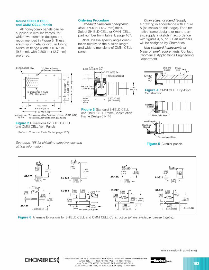
US Headquarters TEL +(1) 781-935-4850 FAX +(1) 781-933-4318 • www.chomerics.comEurope TEL +(44) 1628 404000 FAX +(44) 1628 404090
Asia Pacific TEL +(852) 2 428 8008 FAX +(852) 2 423 8253South America TEL +(55) 11 3917 1099 FAX +(55) 11 3917 0817 163
Round SHIELD CELLand OMNI CELL Panels
All honeycomb panels can besupplied in circular frames, forwhich two common designs arerecommended in Figure 5. Theseare of spun metal or circular tubing.Minimum flange width is 0.375 in.(9.5 mm), with 0.500 in. (12.7 mm)preferred.
0.062(1.57)
1.125(28.58)
0.625(15.88)
0.062(1.57)
0.500(12.70)
1.125(28.58)
0.625(15.88)
1.437(36.50)
0.062(1.57)
0.625(15.88)
0.625(15.88)
0.375(9.52)
0.500(12.70)
0.875(22.22)
0.062(1.57)
0.062(1.57)
0.375(9.52)
0.312(7.92)
0.060 (1.52)
0.080(2.03)
0.190(4.83)
1.040(26.42)
1.125 (28.58)
0.733(18.62)
1.125 (28.58)
0.312(7.92)
0.060 (1.52)
0.080(2.03)
0.190(4.83)
0.750(19.05)
0.733(18.62)
0.380(9.64)
0.380
(9.64)
1.000 (25.40)
0.400(10.16)
0.192(4.88)
0.080(2.30)
0.380(9.64)
61-125 61-123 61-195 61-311
61-31561-21761-183
61-161
ShieldingGasket
ShieldingGasket
Metal Spinning
Metal Spinnings
Circular Metal Plate
Figure 6 Alternate Extrusions for SHIELD CELL and OMNI CELL Construction (others available, please inquire).
Figure 5 Circular panels
(mm dimensions in parentheses)
C
See
Not
e*
A -
0.50
0 (1
2.70
)
"A"
±0.0
31 (
.78)
See Note*
B -0.500 (12.70)
"B" ±0.031 (0.78)
D
0.250 (6.35)Typical
SHIELD CELL & OMNICELL Honeycomb
0.125 (3.18) R. Max. "U" Slots in Gasketat Fastener Locations
*Tolerances on Hole Fastener Locations ±0.015 (0.38)Tolerances Apply Up to 24 in. (60.96 cm)
A = 30°45°60°
ShieldingGasket
IntakeAxis A
Figure 4 OMNI CELL Drip-ProofConstruction
Ordering ProcedureStandard aluminum honeycomb
size: 0.500 in. (12.7 mm) thick.Select SHIELD CELL or OMNI CELLpart number from Table 1, page 167.
Note: Please specify angle orien-tation relative to the outside lengthand width dimensions of OMNI CELLpanel.
0.500 ±0.006(12.70 ±0.15)
0.500(12.70)
0.625 ± 0.010(15.88 ±0.25)
0.250 (6.35) Typ.
(2.360.093+0.031-0.015
+0.790.38 )
#8-32CaptiveInsert
Shielding Gasket
Figure 2 Dimensions for SHIELD CELLand OMNI CELL Vent Panels
Other sizes, or round: Supplya drawing in accordance with FigureA (as shown on this page). For alter-native frame designs or round pan-els, supply a sketch in accordancewith figures 4, 5, or 6. Part numberswill be assigned by Chomerics.
Non-standard honeycomb, orbrass or steel requirements: ContactChomerics’ Applications EngineeringDepartment.
(Refer to Common Parts Table, page 167)
See page 168 for shielding effectiveness andairflow information.
Figure 3 Standard SHIELD CELLand OMNI CELL Frame ConstructionFrame Design 61-118
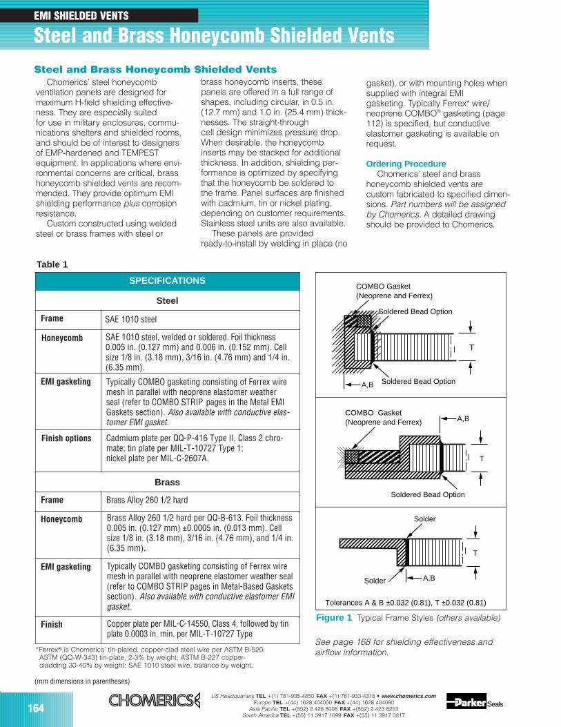
164US Headquarters TEL +(1) 781-935-4850 FAX +(1) 781-933-4318 • www.chomerics.com
Europe TEL +(44) 1628 404000 FAX +(44) 1628 404090Asia Pacific TEL +(852) 2 428 8008 FAX +(852) 2 423 8253
South America TEL +(55) 11 3917 1099 FAX +(55) 11 3917 0817
EMI SHIELDED VENTS
Steel and Brass Honeycomb Shielded Vents
Chomerics’ steel honeycombventilation panels are designed formaximum H-field shielding effective-ness. They are especially suitedfor use in military enclosures, commu-nications shelters and shielded rooms,and should be of interest to designersof EMP-hardened and TEMPESTequipment. In applications where envi-ronmental concerns are critical, brasshoneycomb shielded vents are recom-mended. They provide optimum EMIshielding performance plus corrosionresistance.
Custom constructed using weldedsteel or brass frames with steel or
SPECIFICATIONS
Steel
Frame SAE 1010 steel
Honeycomb
EMI gasketing
Finish options
Frame
Honeycomb
EMI gasketing
Finish
Brass
*Ferrex® is Chomerics’ tin-plated, copper-clad steel wire per ASTM B-520.ASTM (QQ-W-343) tin-plate, 2-3% by weight; ASTM B-227 copper-cladding 30-40% by weight; SAE 1010 steel wire, balance by weight.
COMBO Gasket(Neoprene and Ferrex)
T
A,B
Soldered Bead Option
Solder
Solder A,B
T
COMBO Gasket(Neoprene and Ferrex)
Soldered Bead Option
Soldered Bead Option
T
A,B
Tolerances A & B ±0.032 (0.81), T ±0.032 (0.81)
Figure 1 Typical Frame Styles (others available)
brass honeycomb inserts, thesepanels are offered in a full range ofshapes, including circular, in 0.5 in.(12.7 mm) and 1.0 in. (25.4 mm) thick-nesses. The straight-throughcell design minimizes pressure drop.When desirable, the honeycombinserts may be stacked for additionalthickness. In addition, shielding per-formance is optimized by specifyingthat the honeycomb be soldered tothe frame. Panel surfaces are finishedwith cadmium, tin or nickel plating,depending on customer requirements.Stainless steel units are also available.
These panels are provided ready-to-install by welding in place (no
gasket), or with mounting holes whensupplied with integral EMIgasketing. Typically Ferrex* wire/neoprene COMBO® gasketing (page112) is specified, but conductive elastomer gasketing is available onrequest.
Ordering ProcedureChomerics’ steel and brass
honeycomb shielded vents arecustom fabricated to specified dimen-sions. Part numbers will be assignedby Chomerics. A detailed drawingshould be provided to Chomerics.
Steel and Brass Honeycomb Shielded Vents
(mm dimensions in parentheses)
See page 168 for shielding effectiveness andairflow information.
Table 1
SAE 1010 steel, welded or soldered. Foil thickness0.005 in. (0.127 mm) and 0.006 in. (0.152 mm). Cellsize 1/8 in. (3.18 mm), 3/16 in. (4.76 mm) and 1/4 in.(6.35 mm).
Typically COMBO gasketing consisting of Ferrex wiremesh in parallel with neoprene elastomer weatherseal (refer to COMBO STRIP pages in the Metal EMIGaskets section). Also available with conductive elas-tomer EMI gasket.
Cadmium plate per QQ-P-416 Type II, Class 2 chro-mate; tin plate per MIL-T-10727 Type 1;nickel plate per MIL-C-2607A.
Brass Alloy 260 1/2 hard
Brass Alloy 260 1/2 hard per QQ-B-613. Foil thickness0.005 in. (0.127 mm) ±0.0005 in. (0.013 mm). Cellsize 1/8 in. (3.18 mm), 3/16 in. (4.76 mm), and 1/4 in.(6.35 mm).
Typically COMBO gasketing consisting of Ferrex wiremesh in parallel with neoprene elastomer weather seal(refer to COMBO STRIP pages in Metal-Based Gasketssection). Also available with conductive elastomer EMIgasket.
Copper plate per MIL-C-14550, Class 4, followed by tinplate 0.0003 in. min. per MIL-T-10727 Type
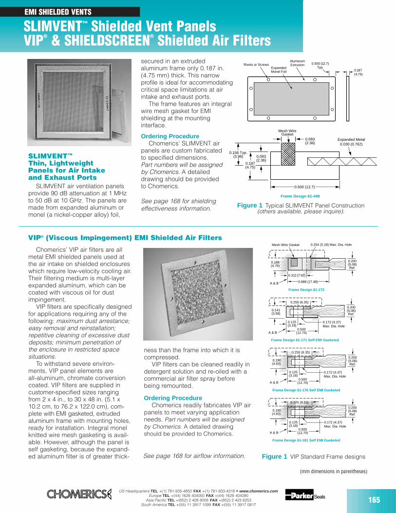
US Headquarters TEL +(1) 781-935-4850 FAX +(1) 781-933-4318 • www.chomerics.comEurope TEL +(44) 1628 404000 FAX +(44) 1628 404090
Asia Pacific TEL +(852) 2 428 8008 FAX +(852) 2 423 8253South America TEL +(55) 11 3917 1099 FAX +(55) 11 3917 0817
165
Frame Design 61-172
Mesh Wire Gasket 0.204 (5.18) Max. Dia. Hole
0.200(5.08)Ref.
0.312 (7.92)
0.688 (17.48)A & B
0.188(4.78)
0.172 (4.37)Max. Dia. Hole
0.200(5.08)Ref.
0.141 (3.58)
0.125(3.18)
0.500(12.70)A & B
Frame Design 61-171 Self EMI Gasketed
0.250 (6.35)
0.172 (4.37)Max. Dia. Hole
0.200(5.08)Ref.
0.190(4.83)
0.125(3.18)
0.500(12.70)A & B
Frame Design 61-176 Self EMI Gasketed
0.250 (6.35)
0.172 (4.37)Max. Dia. Hole
0.200(5.08)Ref.
0.190(4.83)
0.125(3.18)
0.500(12.70)A & B
Frame Design 61-181 Self EMI Gasketed
0.375 (9.53)
SLIMVENTTM
Thin, LightweightPanels for Air Intakeand Exhaust Ports
SLIMVENT air ventilation panelsprovide 90 dB attenuation at 1 MHz to 50 dB at 10 GHz. The panels aremade from expanded aluminum ormonel (a nickel-copper alloy) foil,
Figure 1 VIP Standard Frame designs
Figure 1 Typical SLIMVENT Panel Construction(others available, please inquire).
(mm dimensions in parentheses)
Chomerics’ VIP air filters are allmetal EMI shielded panels used atthe air intake on shielded enclosureswhich require low-velocity cooling air.Their filtering medium is multi-layerexpanded aluminum, which can becoated with viscous oil for dustimpingement.
VIP filters are specifically designedfor applications requiring any of thefollowing: maximum dust arrestance;easy removal and reinstallation;repetitive cleaning of excessive dustdeposits; minimum penetration ofthe enclosure in restricted spacesituations.
To withstand severe environ-ments, VIP panel elements areall-aluminum, chromate conversioncoated. VIP filters are supplied incustomer-specified sizes rangingfrom 2 x 4 in., to 30 x 48 in. (5.1 x10.2 cm, to 76.2 x 122.0 cm), com-plete with EMI gasketed, extruded aluminum frame with mounting holes,ready for installation. Integral monelknitted wire mesh gasketing is avail-able. However, although the panel isself gasketing, because the expand-ed aluminum filter is of greater thick-
ness than the frame into which it iscompressed.
VIP filters can be cleaned readily indetergent solution and re-oiled with acommercial air filter spray beforebeing remounted.
Ordering ProcedureChomerics readily fabricates VIP air
panels to meet varying applicationneeds. Part numbers will be assignedby Chomerics. A detailed drawingshould be provided to Chomerics.
secured in an extrudedaluminum frame only 0.187 in.(4.75 mm) thick. This narrowprofile is ideal for accommodatingcritical space limitations at airintake and exhaust ports.
The frame features an integralwire mesh gasket for EMIshielding at the mountinginterface.
Ordering ProcedureChomerics’ SLIMVENT air
panels are custom fabricatedto specified dimensions. Part numbers will be assignedby Chomerics. A detaileddrawing should be providedto Chomerics.
Mesh Wire Gasket
Expanded Metal0.030 (0.762)
0.187(4.75)
0.156 Typ.(3.96)
0.093(2.36)
0.093(2.36)
0.500 (12.7)
0.187(4.75)
0.500 (12.7)Typ.
Rivets or ScrewsExpandedMonel Foil
AluminumExtrusion
Frame Design 61-448
VIP® (Viscous Impingement) EMI Shielded Air Filters
EMI SHIELDED VENTS
SLIMVENT™ Shielded Vent Panels VIP® & SHIELDSCREEN® Shielded Air Filters
See page 168 for airflow information.
See page 168 for shieldingeffectiveness information.
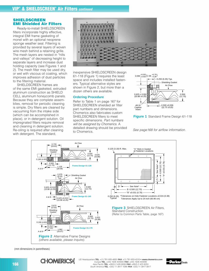
166US Headquarters TEL +(1) 781-935-4850 FAX +(1) 781-933-4318 • www.chomerics.com
Europe TEL +(44) 1628 404000 FAX +(44) 1628 404090Asia Pacific TEL +(852) 2 428 8008 FAX +(852) 2 423 8253
South America TEL +(55) 11 3917 1099 FAX +(55) 11 3917 0817
0.500(12.70)
Air Flow
0.500(12.70) 0.625
(15.88)
Air Flow
0.625 ±0.010(15.88 ±0.25)
0.375(9.53)Typ.
A & B
A & B
0.625 ±0.010(15.98 ±0.25)
Shielding Gasket
0.312(7.92)
0.670(17.02)
0.190 (4.83)
1.062(26.97)
ShieldingGasket
Air Flow
0.500(12.70) 0.625
(15.88)0.190 (4.83)
A & B
0.500(12.70)
1.125(28.58)
0.733(18.62)
ShieldingGasket
Frame Design 61-126
Frame Design 61-140
Frame Design 61-170
Figure 2 Alternative Frame Designs (others available, please inquire).
SHIELDSCREEN EMI Shielded Air Filters
Ready-to-install SHIELDSCREENfilters incorporate highly effective,integral EMI frame gasketing ofmonel with an optional neoprenesponge weather seal. Filtering isprovided by several layers of wovenwire mesh behind a retaining grille.The mesh layers are nested in “hillsand valleys” of decreasing height toseparate layers and increase dustholding capacity (see Figures 1 and2). The mesh filter may be used dry,or wet with viscous oil coating, whichimproves adhesion of dust particlesto the filtering material.
SHIELDSCREEN frames areof the same EMI gasketed, extrudedaluminum construction as SHIELDCELL aluminum honeycomb panels.Because they are complete assem-blies, removal for periodic cleaningis simple. Dry filters are cleaned byvacuuming from the intake side(which can be accomplished inplace), or in detergent solution. Oilimpregnated filters require removaland cleaning in detergent solution.Re-oiling is required after cleaningwith detergent. The standard,
C
See
Not
e*
A -
0.50
0 (1
2.70
)
"A"
±0.0
31 (
0.78
)
See Note*
B -0.500 (12.70)
"B" ±0.031 (0.78)
D
0.250 (6.35)Typical
0.125 (3.18) R. Max. "U" Slots in Gasketat Fastener Locations
*Tolerances on Hole Fastener Locations ±0.015 (0.38)Tolerances Apply Up to 24 inch (60.96 cm)
Figure 3 SHIELDSCREEN Air Filters,Standard Construction(Refer to Common Parts Table, page 167)
inexpensive SHIELDSCREEN design61-118 (Figure 1) requires the leastspace and includes installed fasten-ers. Typical alternative styles areshown in Figure 2, but more than adozen others are available.
Ordering ProcedureRefer to Table 1 on page 167 forSHIELDSCREEN shielded air filterpart numbers and dimensions.Chomerics also fabricates customSHIELDSCREEN filters to meetspecific dimensions. Part numberswill be assigned by Chomerics. Adetailed drawing should be providedto Chomerics.
0.500 ±0.006(12.70 ±0.15)
0.500(12.70)
0.625 ± 0.010(15.88 ±0.25)
0.250 (6.35) Typ.
(2.36+0.031–0.015
+0.79–0.38
)
#8-32CaptiveInsert
Shielding GasketAir Flow
0.093
Figure 1 Standard Frame Design 61-118
(mm dimensions in parentheses)
VIP® & SHIELDSCREEN® Air Filters continued
See page168 for airflow information.
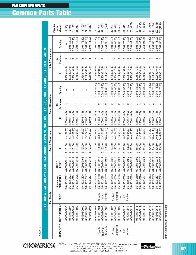
US Headquarters TEL +(1) 781-935-4850 FAX +(1) 781-933-4318 • www.chomerics.comEurope TEL +(44) 1628 404000 FAX +(44) 1628 404090
Asia Pacific TEL +(852) 2 428 8008 FAX +(852) 2 423 8253South America TEL +(55) 11 3917 1099 FAX +(55) 11 3917 0817
167
Tabl
e 1
STAN
DAR
D A
LL-A
LUM
INU
M F
RAM
E D
IMEN
SIO
NS:
SLI
MVE
NT,
SH
IELD
SCR
EEN
, VIP
, OM
NI C
ELL
AND
SH
IELD
CEL
LPA
NEL
S
Part
Num
ber
Ove
rall
Dim
ensi
ons
Side
A D
imen
sion
sSi
de B
Dim
ensi
ons
Effe
ctiv
eAr
eain
2 (cm
2 )SL
IMVE
NT™
VIP®
Alum
inum
OM
NI
CELL
®SH
IELD
CELL
®A
BC
No.
Fast
ener
sSp
acin
gD
No.
Fast
ener
sSp
acin
g
Spec
ify“S
LIM
VEN
T”Ai
r Ven
ts
Cont
act
Chom
eric
sfo
rPa
rtN
umbe
rs
Spec
ify“V
IP”
FILT
ER
Cont
act
Chom
eric
sfo
rPa
rtN
umbe
rs
06-1
102-
0872
06-1
102-
0873
06-1
102-
0874
06-1
102-
0875
06-0
302-
0111
06-0
302-
0112
06-0
302-
0113
06-0
302-
0114
4 (1
01.6
0)4
(101
.60)
4 (1
01.6
0)4
(101
.60)
4 (1
01.6
0)6
(152
.40)
8 (2
03.2
0)12
(304
.80)
1.75
0 (4
4.45
)1.
750
(44.
45)
1.75
0 (4
4.45
)1.
750
(44.
45)
1 1 1 1
– – – –
1.75
0 (4
4.45
)1.
000
(25.
40)
0.75
0 (1
9.05
)1.
250
(31.
75)
1 2 3 4
–3.
500
(88.
90)
3.00
0 (7
6.20
)3.
000
(76.
20)
9 (5
8)15
(97)
21 (1
35)
33 (2
13)
06-1
302-
0900
06-1
302-
0901
06-1
302-
0902
06-1
102-
0876
06-1
102-
0877
06-1
102-
0878
06-0
302-
0108
06-0
302-
0115
06-0
302-
0116
5 (1
27.0
0)5
(127
.00)
5 (1
27.0
0)
5 (1
27.0
0)7
(177
.80)
10 (2
54.0
0)
2.25
0 (5
7.15
)2.
250
(57.
15)
2.25
0 (5
7.15
)
1 1 1
– – –
0.75
0 (1
9.05
)1.
500
(38.
10)
1.25
0 (3
1.75
)
2 2 3
3.00
0 (7
6.20
)3.
500
(88.
90)
3.50
0 (8
8.90
)
16 (1
03)
24 (1
55)
36 (2
32)
06-1
302-
0903
06-1
302-
0904
06-1
302-
0905
06-1
302-
0906
06-1
102-
0879
06-1
102-
0880
06-1
102-
0881
06-1
102-
0882
06-0
302-
0117
06-0
302-
0118
06-0
302-
0119
06-0
302-
0120
6 (1
52.4
0)6
(152
.40)
6 (1
52.4
0)6
(152
.40)
6 (1
52.4
0)8
(203
.20)
12 (3
04.8
0)18
(457
.20)
1.00
0 (2
5.40
)1.
250
(31.
75)
1.00
0 (2
5.40
)1.
000
(25.
40)
2 2 2 2
3.50
0 (8
8.90
)3.
000
(76.
20)
3.50
0 (8
8.90
)3.
500
(88.
90)
1.00
0 (2
5.40
)0.
750
(19.
05)
1.25
0 (3
1.75
)1.
250
(31.
75)
2 3 4 5
3.50
0 (8
8.90
)3.
000
(76.
20)
3.00
0 (7
6.20
)3.
750
(95.
25)
25 (1
61)
35 (2
26)
55 (3
55)
85 (5
48)
06-1
302-
0907
06-1
302-
0908
06-1
302-
0909
06-1
102-
0883
06-1
102-
0884
06-1
102-
0885
06-0
302-
0121
06-0
302-
0122
06-0
302-
0123
7 (1
77.8
0)7
(177
.80)
7 (1
77.8
0)
7 (1
77.8
0)10
(254
.00)
14 (3
55.6
0)
1.50
0 (3
8.10
)1.
500
(38.
10)
1.50
0 (3
8.10
)
2 2 2
3.50
0 (8
8.90
)3.
500
(88.
90)
3.50
0 (8
8.90
)
1.50
0 (3
8.10
)1.
250
(31.
75)
1.50
0 (3
8.10
)
2 3 4
3.50
0 (8
8.90
)3.
500
(88.
90)
3.50
0 (8
8.90
)
36 (2
32)
54 (3
48)
78 (5
03)
06-1
302-
0910
06-1
302-
0911
06-1
302-
0912
06-1
102-
0886
06-1
102-
0887
06-1
102-
0888
06-0
302-
0124
06-0
302-
0125
06-0
302-
0126
8 (2
03.2
0)8
(203
.20)
8 (2
03.2
0)
8 (2
03.2
0)12
(304
.80)
16 (4
06.4
0)
2.00
0 (5
0.80
)0.
750
(19.
05)
0.75
0 (1
9.05
)
2 3 3
3.50
0 (8
8.90
)3.
000
(76.
20)
3.00
0 (7
6.20
)
0.75
0 (1
9.05
)1.
250
(31.
75)
1.25
0 (3
1.75
)
3 4 5
3.00
0 (7
6.20
)3.
000
(76.
20)
3.25
0 (8
2.55
)
49 (3
16)
77 (4
97)
105
(677
)
06-1
302-
0913
06-1
302-
0914
06-1
302-
0915
06-1
102-
0889
06-1
102-
0890
06-1
102-
0891
06-0
302-
0109
06-0
302-
0127
06-0
302-
0128
10 (2
54.0
0)10
(254
.00)
10 (2
54.0
0)
10 (2
54.0
0)14
(355
.60)
18 (4
57.2
0)
1.25
0 (3
1.75
)1.
250
(31.
75)
1.25
0 (3
1.75
)
3 3 3
3.50
0 (8
8.90
)3.
500
(88.
90)
3.50
0 (8
8.90
)
1.25
0 (3
1.75
)1.
500
(38.
10)
1.25
0 (3
1.75
)
3 4 5
3.50
0 (8
8.90
)3.
500
(88.
90)
3.75
0 (9
5.25
)
81 (5
22)
117
(755
)15
3(9
87)
06-1
302-
0916
06-1
302-
0917
06-1
302-
0918
06-1
302-
0919
06-1
102-
0892
06-1
102-
0893
06-1
102-
0894
06-1
102-
0895
06-0
302-
0129
06-0
302-
0110
06-0
302-
0083
06-0
302-
0130
12 (3
04.8
0)12
(304
.80)
12 (3
04.8
0)12
(304
.80)
12 (3
04.8
0)16
(406
.40)
20 (5
08.0
0)24
(609
.60)
1.25
0 (3
1.75
)1.
250
(31.
75)
1.25
0 (3
1.75
)1.
250
(31.
75)
4 4 4 4
3.00
0 (7
6.20
)3.
000
(76.
20)
3.00
0 (7
6.20
)3.
000
(76.
20)
1.25
0 (3
1.75
)1.
250
(31.
75)
1.00
0 (2
5.40
)1.
250
(31.
75)
4 5 6 7
3.00
0 (7
6.20
)3.
250
(82.
55)
3.50
0 (8
8.90
)3.
500
(88.
90)
121
(780
)16
5 (1
064)
209
(134
8)25
3(1
632)
SHIE
LDSC
REE
N®
06-1
302-
0896
06-1
302-
0897
06-1
302-
0898
06-1
302-
0899
EMI SHIELDED VENTS
Common Parts Table
(mm
dim
ensi
ons
in p
aren
thes
es)
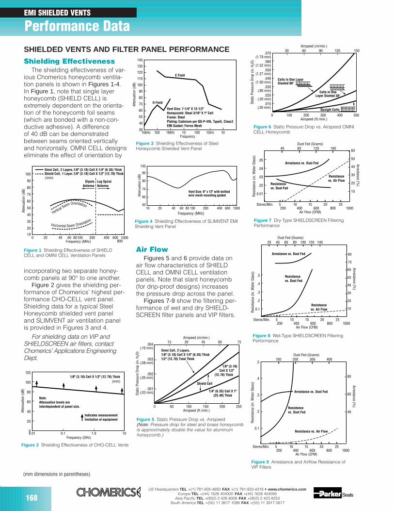
168US Headquarters TEL +(1) 781-935-4850 FAX +(1) 781-933-4318 • www.chomerics.com
Europe TEL +(44) 1628 404000 FAX +(44) 1628 404090Asia Pacific TEL +(852) 2 428 8008 FAX +(852) 2 423 8253
South America TEL +(55) 11 3917 1099 FAX +(55) 11 3917 0817
Shielding EffectivenessThe shielding effectiveness of var-
ious Chomerics honeycomb ventila-tion panels is shown in Figures 1-4.In Figure 1, note that single layerhoneycomb (SHIELD CELL) isextremely dependent on the orienta-tion of the honeycomb foil seams(which are bonded with a non-con-ductive adhesive). A differenceof 40 dB can be demonstratedbetween seams oriented verticallyand horizontally. OMNI CELL designseliminate the effect of orientation by
EMI SHIELDED VENTS
Performance DataSHIELDED VENTS AND FILTER PANEL PERFORMANCE
Air FlowFigures 5 and 6 provide data on
air flow characteristics of SHIELDCELL and OMNI CELL ventilationpanels. Note that slant honeycomb(for drip-proof designs) increasesthe pressure drop across the panel.
Figures 7-9 show the filtering per-formance of wet and dry SHIELD-SCREEN filter panels and VIP filters.
incorporating two separate honey-comb panels at 90° to one another.
Figure 2 gives the shielding per-formance of Chomerics’ highest per-formance CHO-CELL vent panel.Shielding data for a typical SteelHoneycomb shielded vent paneland SLIMVENT air ventilation panelis provided in Figures 3 and 4.
For shielding data on VIP andSHIELDSCREEN air filters, contactChomerics’ Applications EngineeringDept.
Frequency (MHz)
Omni Cell, 2 Layers,1/8" (3.18) Cell X 1/4" (6.35) ThickShield Cell, 1 Layer,1/8" (3.18) Cell X 1/2" (12.70) Thick
20
10
30
40
50
60
70
80
90
100
0 20 40 60 80100 200 400 600800
Atte
nuat
ion
(dB)
Horizontal Seam Orientation
Vertical Seam Orientation
1000
Log SpiralAntenna
DipoleAntenna
(mm)
Figure 1 Shielding Effectiveness of SHIELDCELL and OMNI CELL Ventilation Panels
Frequency (GHz)
Atte
nuat
ion
(dB)
0
20
40
60
80
100
120
0.01 0.1 1.0 10
Note:Attenuation levels areinterdependent of panel size.
Indicates measurementlimitation of equipment
1/8" (3.18) Cell X 1/2" (12.70) Thick(mm)
Figure 2 Shielding Effectiveness of CHO-CELL Vents
Atte
nuat
ion
(dB)
40
30
50
60
70
80
90
100
110
120
130
140
10kHz 100 1MHz 10 100 1GHz 10Frequency
H Field
E Field
Vent Size: 7-1/4" X 12-1/2"Honeycomb: Steel 3/16" X 1" CellFrame: Steel Plating: Cadmium per QQ-P-416, Type II, Class 2EMI Gasket: Ferrex Mesh
Figure 3 Shielding Effectiveness of SteelHoneycomb Shielded Vent Panel
100
90
80
70
60
5010 20 40 60 80 1000
Frequency (MHz)
Atte
nuat
ion
(dB)
100 200 400 600
Vent Size: 6" x 12" with knittedwire mesh mounting gasket
Figure 4 Shielding Effectiveness of SLIMVENT EMIShielding Vent Panel
Stat
ic P
ress
ure
Dro
p (in
. H2O
)
.001(.03 mm)
.002(.05 mm)
.003(.08 mm)
.004(.10 mm)
0 50 100 150 200
15 30 45 60 75
250Airspeed (ft./min.)
Airspeed (m/min.)
Omni Cell, 2 Layers,1/8" (3.18) Cell X 1/4" (6.35) Thick1/2" (12.70) Total Thick
1/8" (3.18) Cell X 1/2"(12.70) Thick
1/4" (6.35) Cell X 1"(25.40) Thick
Shield Cell
Figure 5 Static Pressure Drop vs. Airspeed(Note: Pressure drop for steel and brass honeycombis approximately double the value for aluminum honeycomb.)
Stat
ic P
ress
ure
Dro
p (in
. H2O
)
.070(1.78 mm)
.060(1.52 mm)
.050(1.27 mm)
.040(1.00 mm)
.030(.80 mm)
.020(.50 mm)
.010(.30 mm)
0 100 200 300 400
30 60 90 120 150
500Airspeed (ft./min.)
Airspeed (m/min.)
IntakeAxis Intake
Axis
Cells in OneLayer Slanted 30°
Cells in One LayerSlanted 60°
Straight Cells
IntakeAxis
Figure 6 Static Pressure Drop vs. Airspeed OMNICELL Honeycomb
0.01
.02
.03
.04
.05
10
20
30
40
50
60
Air Flow (CFM)
Dust Fed (Grams)
200 400 600 800
40 80 120 160
10005 10 15 20
Res
ista
nce
(in. W
ater
Gla
ss)
Steres/Min. 25
Resistancevs. Dust Fed
Arrestance vs. Dust Fed
Resistancevs. Air Flow
Arrestance (%)
Figure 7 Dry-Type SHIELDSCREEN FilteringPerformance
0.1
.2
.3
.4
.5
10
20
30
40
50
60
70
80
Air Flow (CFM)
Dust Fed (Grams)
200 400 600 800
20 40 60 80 100
10005 10 15 20
Res
ista
nce
(in. W
ater
Gla
ss)
Steres/Min. 25
120 140
Resistancevs. Dust Fed
Arrestance vs. Dust Fed
Resistancevs. Air Flow
Arrestance (%)
Figure 8 Wet-Type SHIELDSCREEN FilteringPerformance
0.1
.2
.3
.4
.5
Air Flow (CFM)200 400 600 800 1000
5 10 15 20
Res
ista
nce
(in. W
ater
Gla
ss)
Steres/Min. 25
Resistancevs. Dust Fed
Arrestance vs. Dust Fed
Resistance vs. Air Flow
Dust Fed (Grams)100 200 300 400
Arrestance (%)
40
60
80
Figure 9 Arrestance and Airflow Resistance of VIP Filters
(mm dimensions in parentheses)
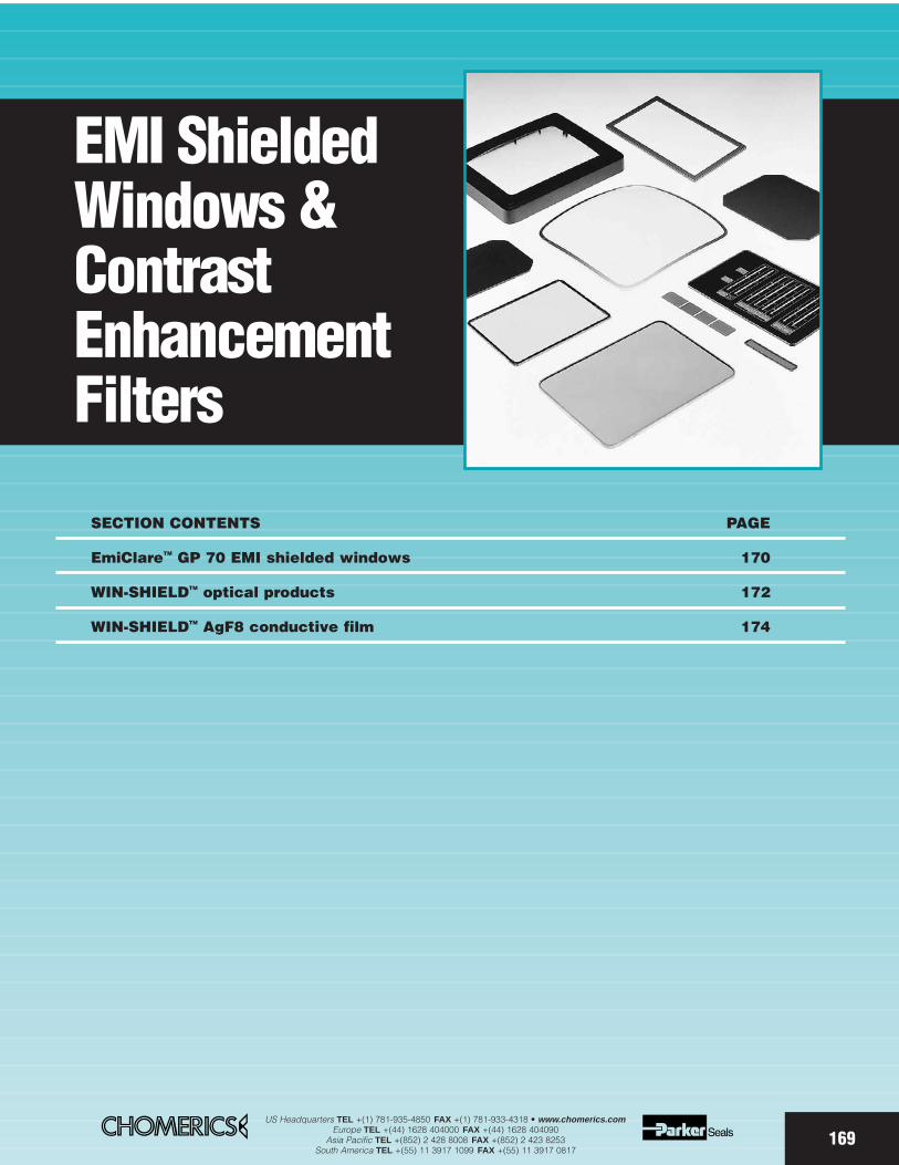
EMI ShieldedWindows &ContrastEnhancementFilters
SECTION CONTENTS PAGE
EmiClareTM GP 70 EMI shielded windows 170
WIN-SHIELDTM optical products 172
WIN-SHIELDTM AgF8 conductive film 174
169US Headquarters TEL +(1) 781-935-4850 FAX +(1) 781-933-4318 • www.chomerics.com
Europe TEL +(44) 1628 404000 FAX +(44) 1628 404090Asia Pacific TEL +(852) 2 428 8008 FAX +(852) 2 423 8253
South America TEL +(55) 11 3917 1099 FAX +(55) 11 3917 0817
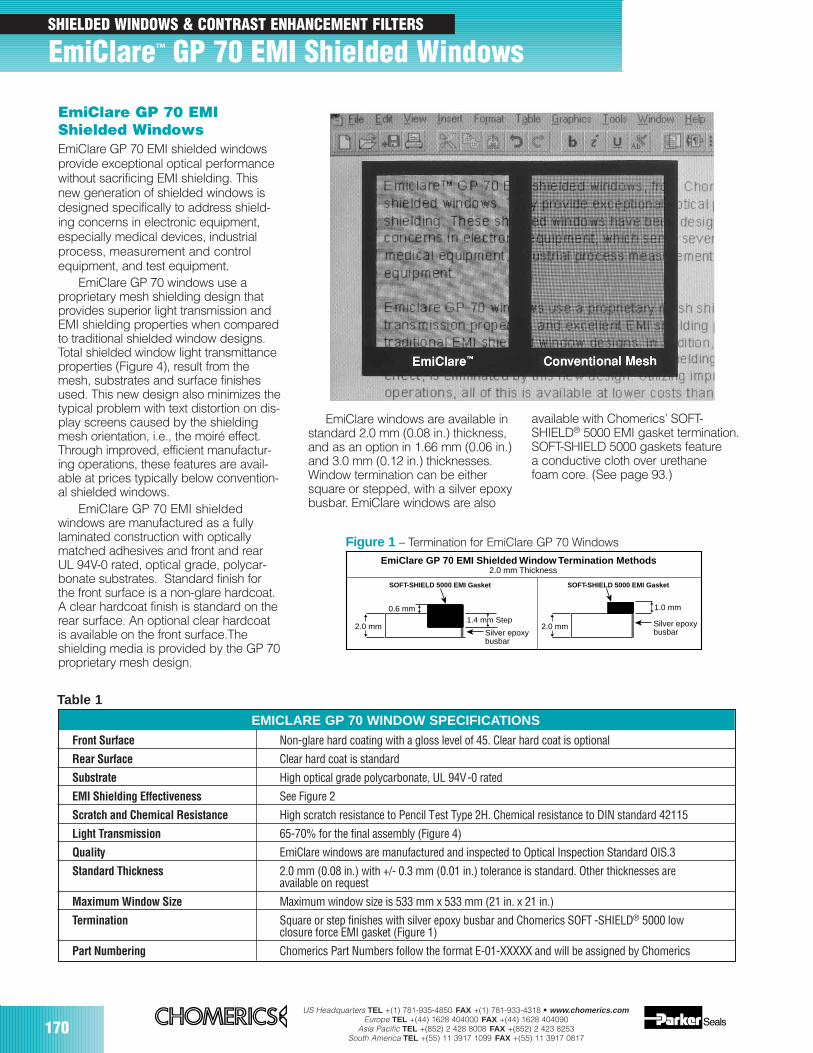
170US Headquarters TEL +(1) 781-935-4850 FAX +(1) 781-933-4318 • www.chomerics.com
Europe TEL +(44) 1628 404000 FAX +(44) 1628 404090Asia Pacific TEL +(852) 2 428 8008 FAX +(852) 2 423 8253
South America TEL +(55) 11 3917 1099 FAX +(55) 11 3917 0817
0.6 mm
SOFT-SHIELD 5000 EMI Gasket SOFT-SHIELD 5000 EMI Gasket
2.0 mm1.4 mm Step
Silver epoxy busbar
EmiClare GP 70 EMI Shielded Window Termination Methods2.0 mm Thickness
2.0 mm
1.0 mm
Silver epoxy busbar
Table 1
Front Surface Non-glare hard coating with a gloss level of 45. Clear hard coat is optional
Rear Surface Clear hard coat is standard
Substrate High optical grade polycarbonate, UL 94V-0 rated
EMI Shielding Effectiveness See Figure 2
Scratch and Chemical Resistance High scratch resistance to Pencil Test Type 2H. Chemical resistance to DIN standard 42115
Light Transmission 65-70% for the final assembly (Figure 4)
Quality EmiClare windows are manufactured and inspected to Optical Inspection Standard OIS.3
Standard Thickness 2.0 mm (0.08 in.) with +/- 0.3 mm (0.01 in.) tolerance is standard. Other thicknesses areavailable on request
Maximum Window Size Maximum window size is 533 mm x 533 mm (21 in. x 21 in.)
Termination Square or step finishes with silver epoxy busbar and Chomerics SOFT -SHIELD® 5000 low closure force EMI gasket (Figure 1)
Part Numbering Chomerics Part Numbers follow the format E-01-XXXXX and will be assigned by Chomerics
Figure 1 – Termination for EmiClare GP 70 Windows
EmiClare GP 70 EMIShielded WindowsEmiClare GP 70 EMI shielded windowsprovide exceptional optical performancewithout sacrificing EMI shielding. Thisnew generation of shielded windows isdesigned specifically to address shield-ing concerns in electronic equipment,especially medical devices, industrialprocess, measurement and controlequipment, and test equipment.
EmiClare GP 70 windows use a proprietary mesh shielding design thatprovides superior light transmission andEMI shielding properties when comparedto traditional shielded window designs.Total shielded window light transmittanceproperties (Figure 4), result from themesh, substrates and surface finishesused. This new design also minimizes thetypical problem with text distortion on dis-play screens caused by the shieldingmesh orientation, i.e., the moiré effect.Through improved, efficient manufactur-ing operations, these features are avail-able at prices typically below convention-al shielded windows.
EmiClare GP 70 EMI shielded windows are manufactured as a fully laminated construction with opticallymatched adhesives and front and rearUL 94V-0 rated, optical grade, polycar-bonate substrates. Standard finish forthe front surface is a non-glare hardcoat.A clear hardcoat finish is standard on therear surface. An optional clear hardcoatis available on the front surface.Theshielding media is provided by the GP 70proprietary mesh design.
EmiClare windows are available instandard 2.0 mm (0.08 in.) thickness,and as an option in 1.66 mm (0.06 in.)and 3.0 mm (0.12 in.) thicknesses.Window termination can be eithersquare or stepped, with a silver epoxybusbar. EmiClare windows are also
available with Chomerics’ SOFT-SHIELD® 5000 EMI gasket termination.SOFT-SHIELD 5000 gaskets feature a conductive cloth over urethane foam core. (See page 93.)
SHIELDED WINDOWS & CONTRAST ENHANCEMENT FILTERS
EmiClare™ GP 70 EMI Shielded Windows
EMICLARE GP 70 WINDOW SPECIFICATIONS
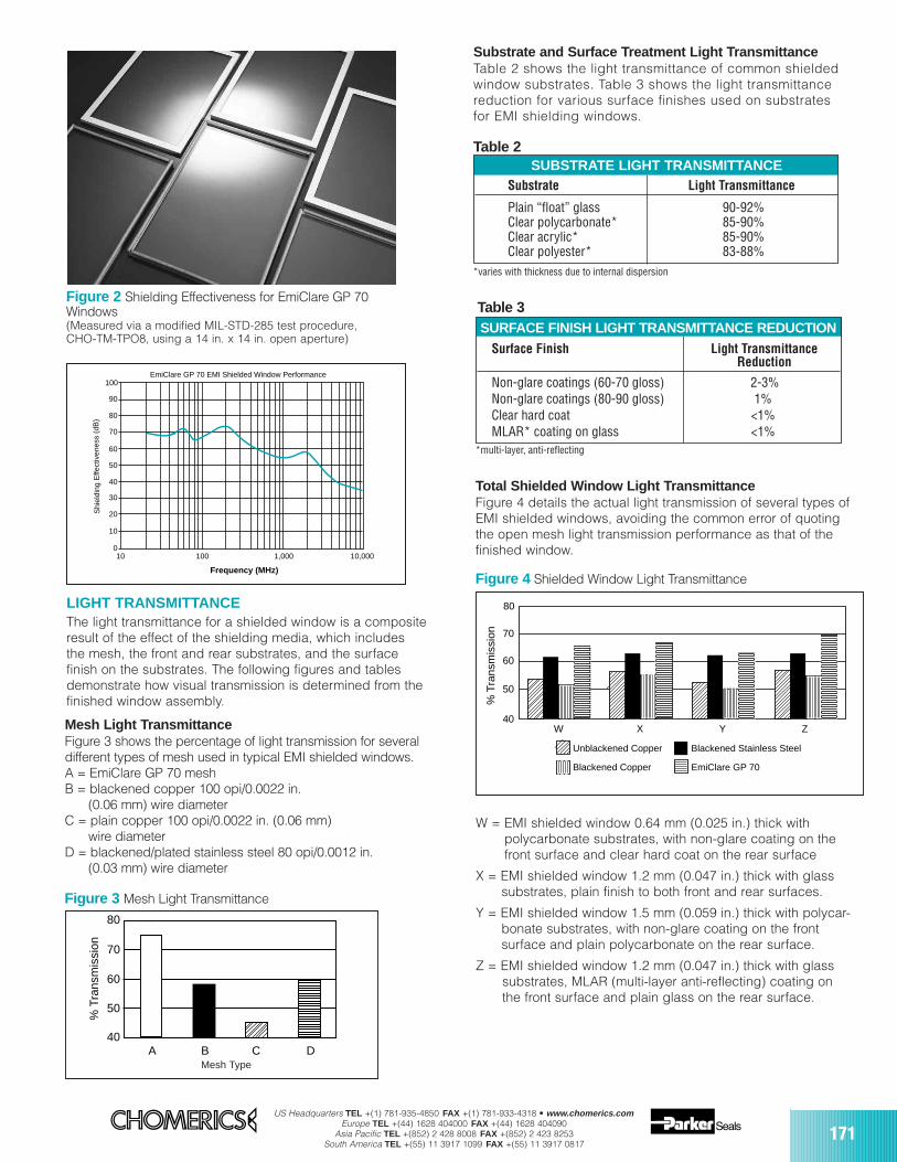
US Headquarters TEL +(1) 781-935-4850 FAX +(1) 781-933-4318 • www.chomerics.comEurope TEL +(44) 1628 404000 FAX +(44) 1628 404090
Asia Pacific TEL +(852) 2 428 8008 FAX +(852) 2 423 8253South America TEL +(55) 11 3917 1099 FAX +(55) 11 3917 0817
171
100
90
80
70
60
50
40
30
20
10
10 100 1,000 10,000 0
Frequency (MHz)
EmiClare GP 70 EMI Shielded Window Performance
Shi
eldi
ng E
ffect
iven
ess
(dB
)
Figure 2 Shielding Effectiveness for EmiClare GP 70Windows(Measured via a modified MIL-STD-285 test procedure, CHO-TM-TPO8, using a 14 in. x 14 in. open aperture)
LIGHT TRANSMITTANCE The light transmittance for a shielded window is a compositeresult of the effect of the shielding media, which includesthe mesh, the front and rear substrates, and the surface finish on the substrates. The following figures and tablesdemonstrate how visual transmission is determined from thefinished window assembly.
Figure 3 Mesh Light Transmittance
Mesh Type
80
70
60
50
40A B C D
% T
rans
mis
sion
Mesh Light TransmittanceFigure 3 shows the percentage of light transmission for severaldifferent types of mesh used in typical EMI shielded windows.A = EmiClare GP 70 meshB = blackened copper 100 opi/0.0022 in.
(0.06 mm) wire diameter C = plain copper 100 opi/0.0022 in. (0.06 mm)
wire diameter D = blackened/plated stainless steel 80 opi/0.0012 in.
(0.03 mm) wire diameter
Substrate Light Transmittance
Plain “float” glass 90-92%Clear polycarbonate* 85-90%Clear acrylic* 85-90%Clear polyester* 83-88%
Table 2
Substrate and Surface Treatment Light TransmittanceTable 2 shows the light transmittance of common shieldedwindow substrates. Table 3 shows the light transmittancereduction for various surface finishes used on substratesfor EMI shielding windows.
Table 3
80
70
60
50
40W X Y Z
% T
rans
mis
sion
Unblackened Copper
Blackened Copper EmiClare GP 70
Blackened Stainless Steel
W = EMI shielded window 0.64 mm (0.025 in.) thick with polycarbonate substrates, with non-glare coating on the front surface and clear hard coat on the rear surface
X = EMI shielded window 1.2 mm (0.047 in.) thick with glasssubstrates, plain finish to both front and rear surfaces.
Y = EMI shielded window 1.5 mm (0.059 in.) thick with polycar-bonate substrates, with non-glare coating on the front surface and plain polycarbonate on the rear surface.
Z = EMI shielded window 1.2 mm (0.047 in.) thick with glass substrates, MLAR (multi-layer anti-reflecting) coating on the front surface and plain glass on the rear surface.
Total Shielded Window Light TransmittanceFigure 4 details the actual light transmission of several types ofEMI shielded windows, avoiding the common error of quotingthe open mesh light transmission performance as that of thefinished window.
Surface Finish Light TransmittanceReduction
Non-glare coatings (60-70 gloss) 2-3%Non-glare coatings (80-90 gloss) 1%Clear hard coat <1%MLAR* coating on glass <1%
Figure 4 Shielded Window Light Transmittance
*multi-layer, anti-reflecting
*varies with thickness due to internal dispersion
Mesh Type
SUBSTRATE LIGHT TRANSMITTANCE
SURFACE FINISH LIGHT TRANSMITTANCE REDUCTION
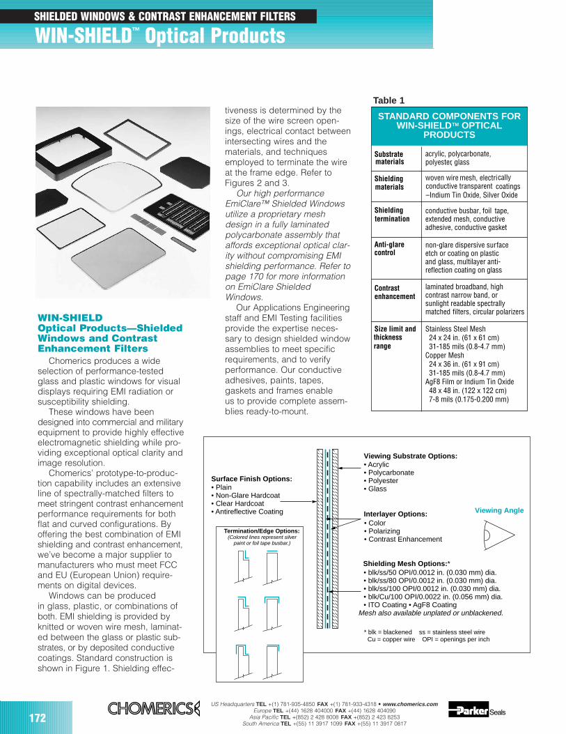
172US Headquarters TEL +(1) 781-935-4850 FAX +(1) 781-933-4318 • www.chomerics.com
Europe TEL +(44) 1628 404000 FAX +(44) 1628 404090Asia Pacific TEL +(852) 2 428 8008 FAX +(852) 2 423 8253
South America TEL +(55) 11 3917 1099 FAX +(55) 11 3917 0817
WIN-SHIELDOptical Products—ShieldedWindows and ContrastEnhancement Filters
Chomerics produces a wideselection of performance-testedglass and plastic windows for visualdisplays requiring EMI radiation orsusceptibility shielding.
These windows have beendesigned into commercial and militaryequipment to provide highly effectiveelectromagnetic shielding while pro-viding exceptional optical clarity andimage resolution.
Chomerics’ prototype-to-produc-tion capability includes an extensiveline of spectrally-matched filters tomeet stringent contrast enhancementperformance requirements for bothflat and curved configurations. Byoffering the best combination of EMIshielding and contrast enhancement,we’ve become a major supplier tomanufacturers who must meet FCCand EU (European Union) require-ments on digital devices.
Windows can be producedin glass, plastic, or combinations ofboth. EMI shielding is provided byknitted or woven wire mesh, laminat-ed between the glass or plastic sub-strates, or by deposited conductivecoatings. Standard construction isshown in Figure 1. Shielding effec-
tiveness is determined by thesize of the wire screen open-ings, electrical contact betweenintersecting wires and thematerials, and techniquesemployed to terminate the wireat the frame edge. Refer toFigures 2 and 3.
Our high performanceEmiClare™ Shielded Windowsutilize a proprietary meshdesign in a fully laminated polycarbonate assembly thataffords exceptional optical clar-ity without compromising EMIshielding performance. Refer topage 170 for more informationon EmiClare ShieldedWindows.
Our Applications Engineeringstaff and EMI Testing facilitiesprovide the expertise neces-sary to design shielded windowassemblies to meet specificrequirements, and to verify performance. Our conductiveadhesives, paints, tapes, gaskets and frames enable us to provide complete assem-blies ready-to-mount.
Substrate materials
acrylic, polycarbonate,polyester, glass
Shielding materials
woven wire mesh, electrically conductive transparent coatings
Shieldingtermination
conductive busbar, foil tape,extended mesh, conductiveadhesive, conductive gasket
Anti-glare control
non-glare dispersive surfaceetch or coating on plasticand glass, multilayer anti-reflection coating on glass
Contrastenhancement
laminated broadband, highcontrast narrow band, orsunlight readable spectrallymatched filters, circular polarizers
Size limit and Stainless Steel Mesh 24 x 24 in. (61 x 61 cm) 31-185 mils (0.8-4.7 mm)Copper Mesh 24 x 36 in. (61 x 91 cm) 31-185 mils (0.8-4.7 mm)AgF8 Film or Indium Tin Oxide 48 x 48 in. (122 x 122 cm) 7-8 mils (0.175-0.200 mm)
STANDARD COMPONENTS FORWIN-SHIELDTM OPTICAL
PRODUCTS
–Indium Tin Oxide, Silver Oxide
thickness range
Table 1
Viewing Angle
* blk = blackened ss = stainless steel wire Cu = copper wire OPI = openings per inch
• Acrylic• Polycarbonate• Polyester• Glass
Interlayer Options:
Viewing Substrate Options:
Shielding Mesh Options:*
• Plain• Non-Glare Hardcoat• Clear Hardcoat• Antireflective Coating
Surface Finish Options:
• Color• Polarizing• Contrast Enhancement
• blk/ss/50 OPI/0.0012 in. (0.030 mm) dia.• blk/ss/80 OPI/0.0012 in. (0.030 mm) dia.• blk/ss/100 OPI/0.0012 in. (0.030 mm) dia.• blk/Cu/100 OPI/0.0022 in. (0.056 mm) dia.• ITO Coating • AgF8 Coating
Mesh also available unplated or unblackened.
Termination/Edge Options:(Colored lines represent silver
paint or foil tape busbar.)
SHIELDED WINDOWS & CONTRAST ENHANCEMENT FILTERS
WIN-SHIELD™ Optical Products
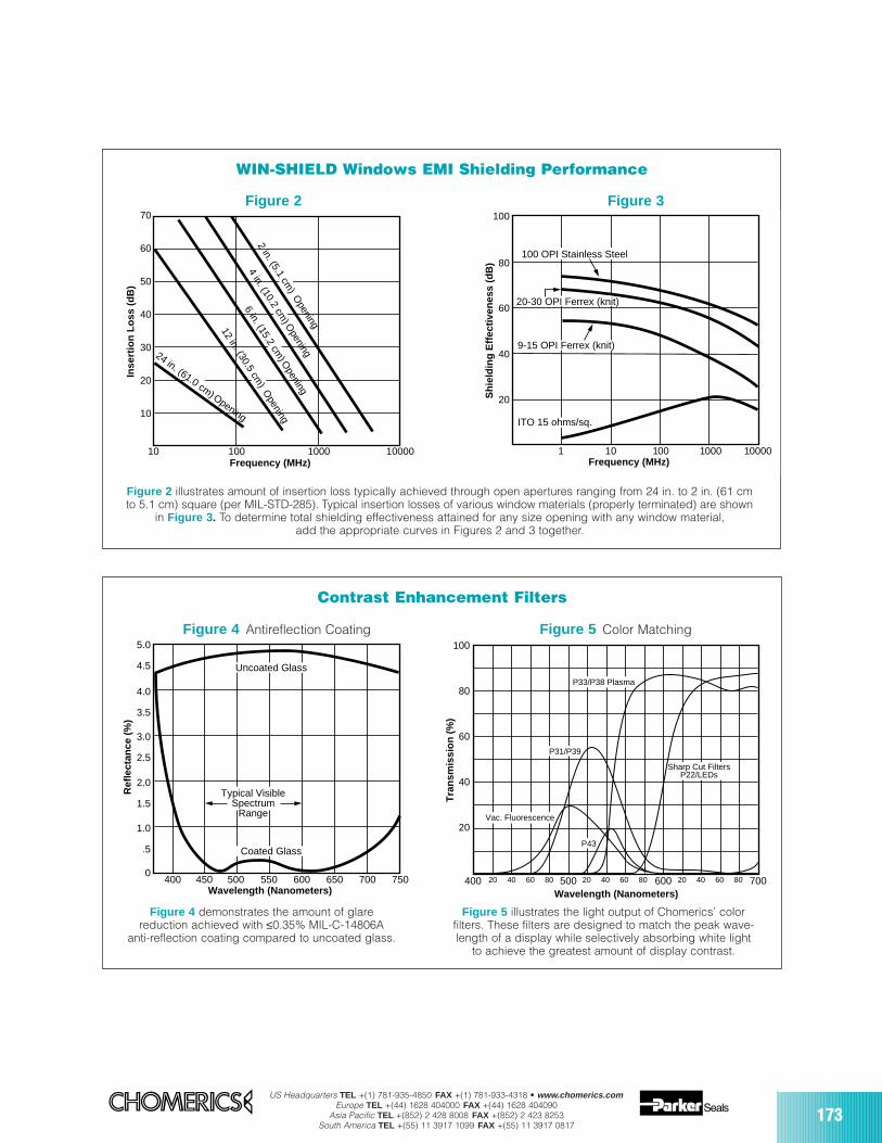
US Headquarters TEL +(1) 781-935-4850 FAX +(1) 781-933-4318 • www.chomerics.comEurope TEL +(44) 1628 404000 FAX +(44) 1628 404090
Asia Pacific TEL +(852) 2 428 8008 FAX +(852) 2 423 8253South America TEL +(55) 11 3917 1099 FAX +(55) 11 3917 0817
173
WIN-SHIELD Windows EMI Shielding Performance
Contrast Enhancement Filters
Figure 2 illustrates amount of insertion loss typically achieved through open apertures ranging from 24 in. to 2 in. (61 cmto 5.1 cm) square (per MIL-STD-285). Typical insertion losses of various window materials (properly terminated) are shown
in Figure 3 . To determine total shielding effectiveness attained for any size opening with any window material,add the appropriate curves in Figures 2 and 3 together.
Figure 4 demonstrates the amount of glarereduction achieved with ≤0.35% MIL-C-14806A
anti-reflection coating compared to uncoated glass.
Figure 2
Figure 5 illustrates the light output of Chomerics’ colorfilters. These filters are designed to match the peak wave-length of a display while selectively absorbing white light
to achieve the greatest amount of display contrast.
P33/P38 Plasma
P31/P39
P43
Sharp Cut FiltersP22/LEDs
Vac. Fluorescence
100
80
60
40
20
500400 600 70020 40 60 80 20 40 60 80 20 40 60 80
Wavelength (Nanometers)
Tra
nsm
issi
on
(%
)
Figure 5 Color Matching
Figure 3
400 450 500 550 600 650 700 750
1.0
2.0
3.0
4.0
5.0
.5
0
1.5
2.5
3.5
4.5
Wavelength (Nanometers)
Ref
lect
ance
(%
)
Uncoated Glass
Coated Glass
Typical VisibleSpectrum
Range
Figure 4 Antireflection Coating
10
10
100 1000 10000
20
30
40
50
60
70
Frequency (MHz)
Inse
rtio
n L
oss
(d
B)
2 in. (5.1 cm) O
pening
4 in. (10.2 cm) O
pening
6 in. (15.2 cm) O
pening
12 in. (30.5 cm) O
pening
24 in. (61.0 cm) Opening
1 10 100 1000 10000
20
40
60
80
100
Frequency (MHz)
Sh
ield
ing
Eff
ecti
ven
ess
(dB
)
20-30 OPI Ferrex (knit)
9-15 OPI Ferrex (knit)
100 OPI Stainless Steel
ITO 15 ohms/sq.
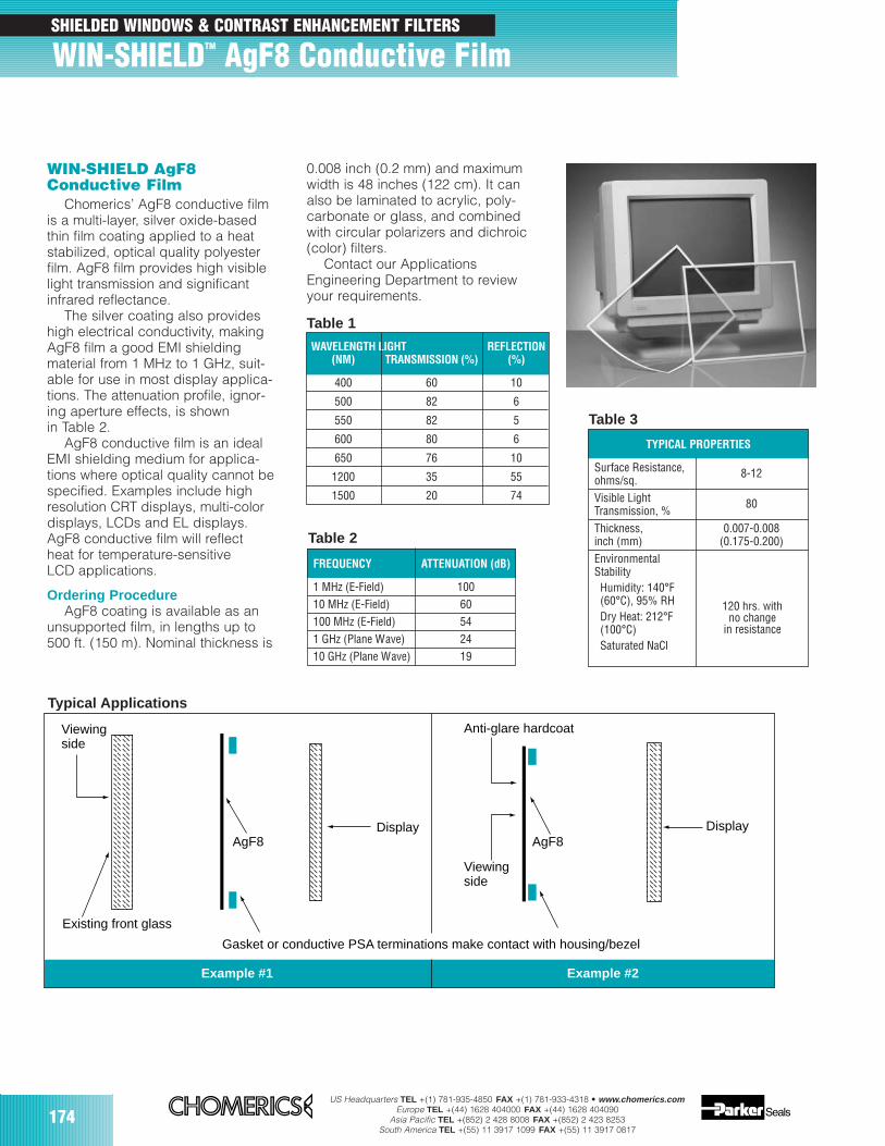
174US Headquarters TEL +(1) 781-935-4850 FAX +(1) 781-933-4318 • www.chomerics.com
Europe TEL +(44) 1628 404000 FAX +(44) 1628 404090Asia Pacific TEL +(852) 2 428 8008 FAX +(852) 2 423 8253
South America TEL +(55) 11 3917 1099 FAX +(55) 11 3917 0817
WAVELENGTH LIGHT REFLECTION(NM) TRANSMISSION (%) (%)
400 60 10
500 82 6
550 82 5
600 80 6
650 76 10
1200 35 55
1500 20 74
WIN-SHIELD AgF8Conductive Film
Chomerics’ AgF8 conductive filmis a multi-layer, silver oxide-basedthin film coating applied to a heatstabilized, optical quality polyesterfilm. AgF8 film provides high visiblelight transmission and significantinfrared reflectance.
The silver coating also provideshigh electrical conductivity, makingAgF8 film a good EMI shieldingmaterial from 1 MHz to 1 GHz, suit-able for use in most display applica-tions. The attenuation profile, ignor-ing aperture effects, is shownin Table 2.
AgF8 conductive film is an idealEMI shielding medium for applica-tions where optical quality cannot bespecified. Examples include highresolution CRT displays, multi-colordisplays, LCDs and EL displays.AgF8 conductive film will reflectheat for temperature-sensitiveLCD applications.
Ordering ProcedureAgF8 coating is available as an
unsupported film, in lengths up to500 ft. (150 m). Nominal thickness is
Table 1
FREQUENCY ATTENUATION (dB)
1 MHz (E-Field) 10010 MHz (E-Field) 60100 MHz (E-Field) 541 GHz (Plane Wave) 2410 GHz (Plane Wave) 19
Table 2
TYPICAL PROPERTIES
Surface Resistance,ohms/sq.
8-12
Visible LightTransmission, %
80
Thickness, 0.007-0.008inch (mm) (0.175-0.200)EnvironmentalStabilityHumidity: 140°F(60°C), 95% RHDry Heat: 212°F(100°C)Saturated NaCl
Table 3
Viewingside
Existing front glass
AgF8 AgF8
Anti-glare hardcoat
Display Display
Viewingside
Example #2
Gasket or conductive PSA terminations make contact with housing/bezel
Example #1
0.008 inch (0.2 mm) and maximumwidth is 48 inches (122 cm). It canalso be laminated to acrylic, poly-carbonate or glass, and combinedwith circular polarizers and dichroic(color) filters.
Contact our ApplicationsEngineering Department to reviewyour requirements.
Typical Applications
120 hrs. withno change
in resistance
174
SHIELDED WINDOWS & CONTRAST ENHANCEMENT FILTERS
WIN-SHIELDTM AgF8 Conductive Film
175
SECTION CONTENTS PAGE
CHO-SORB® EMI ferrites 176
CHO-DROP® EMI absorbers 183
ZIP-EX-2® zippered cable shielding 184
CHO-SHRINK® conductive heat shrinkable shielding 186
CHO-JAC® flat cable EMI shield 189
SHIELD WRAPTM knitted wire mesh tape 190
CableShielding
US Headquarters TEL +(1) 781-935-4850 FAX +(1) 781-933-4318 • www.chomerics.comEurope TEL +(44) 1628 404000 FAX +(44) 1628 404090
Asia Pacific TEL +(852) 2 428 8008 FAX +(852) 2 423 8253South America TEL +(55) 11 3917 1099 FAX +(55) 11 3917 0817
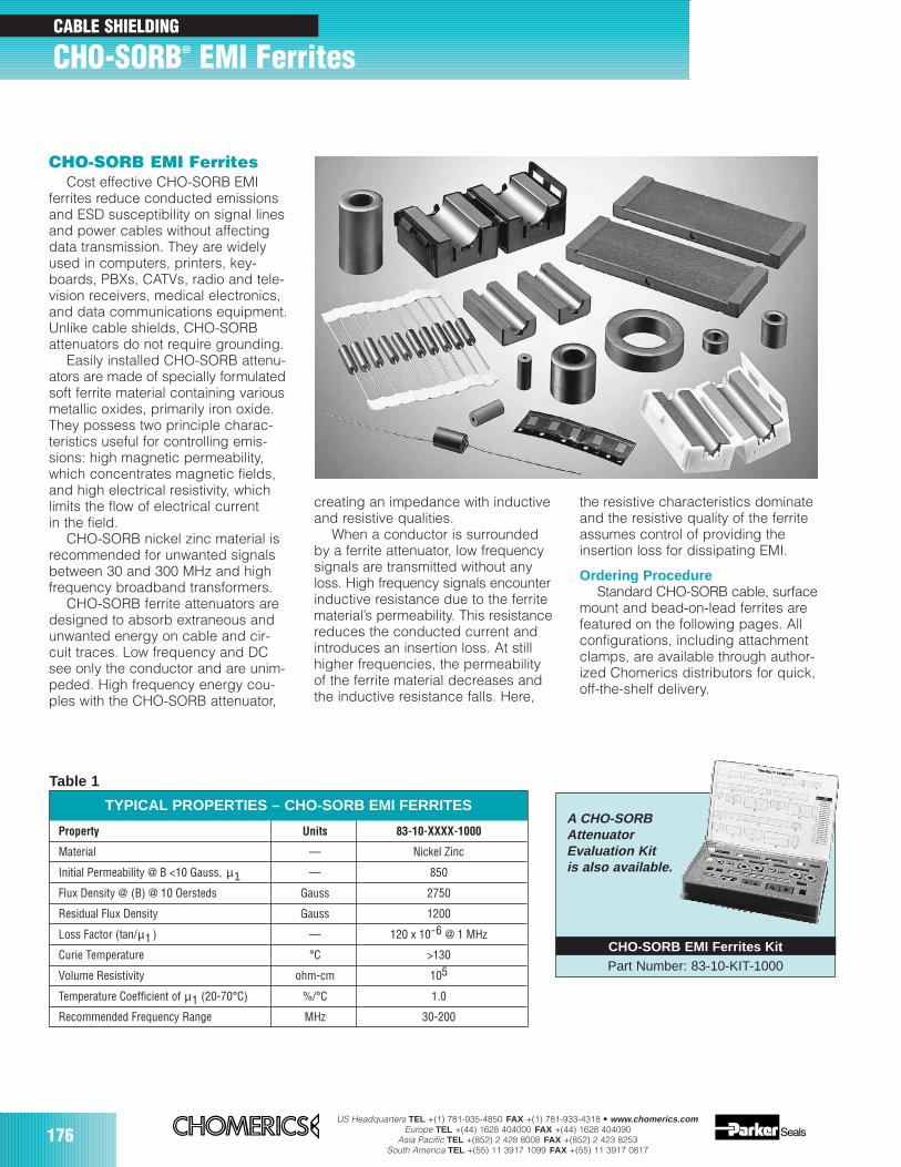
176US Headquarters TEL +(1) 781-935-4850 FAX +(1) 781-933-4318 • www.chomerics.com
Europe TEL +(44) 1628 404000 FAX +(44) 1628 404090Asia Pacific TEL +(852) 2 428 8008 FAX +(852) 2 423 8253
South America TEL +(55) 11 3917 1099 FAX +(55) 11 3917 0817
CABLE SHIELDING
CHO-SORB® EMI Ferrites
CHO-SORB EMI FerritesCost effective CHO-SORB EMI
ferrites reduce conducted emissionsand ESD susceptibility on signal linesand power cables without affectingdata transmission. They are widelyused in computers, printers, key-boards, PBXs, CATVs, radio and tele-vision receivers, medical electronics,and data communications equipment.Unlike cable shields, CHO-SORBattenuators do not require grounding.
Easily installed CHO-SORB attenu-ators are made of specially formulatedsoft ferrite material containing variousmetallic oxides, primarily iron oxide.They possess two principle charac-teristics useful for controlling emis-sions: high magnetic permeability,which concentrates magnetic fields,and high electrical resistivity, whichlimits the flow of electrical currentin the field.
CHO-SORB nickel zinc material isrecommended for unwanted signalsbetween 30 and 300 MHz and highfrequency broadband transformers.
CHO-SORB ferrite attenuators aredesigned to absorb extraneous andunwanted energy on cable and cir-cuit traces. Low frequency and DCsee only the conductor and are unim-peded. High frequency energy cou-ples with the CHO-SORB attenuator,
creating an impedance with inductiveand resistive qualities.
When a conductor is surroundedby a ferrite attenuator, low frequencysignals are transmitted without anyloss. High frequency signals encounterinductive resistance due to the ferritematerial’s permeability. This resistancereduces the conducted current andintroduces an insertion loss. At stillhigher frequencies, the permeabilityof the ferrite material decreases andthe inductive resistance falls. Here,
the resistive characteristics dominateand the resistive quality of the ferriteassumes control of providing theinsertion loss for dissipating EMI.
Ordering ProcedureStandard CHO-SORB cable, surface
mount and bead-on-lead ferrites arefeatured on the following pages. Allconfigurations, including attachmentclamps, are available through author-ized Chomerics distributors for quick,off-the-shelf delivery.
TYPICAL PROPERTIES – CHO-SORB EMI FERRITES
Property Units 83-10-XXXX-1000
Material –– Nickel Zinc
Initial Permeability @ B <10 Gauss, µ1 –– 850
Flux Density @ (B) @ 10 Oersteds Gauss 2750
Residual Flux Density Gauss 1200
Loss Factor (tan/µ1 ) –– 120 x 10-6 @ 1 MHz
Curie Temperature °C >130
Volume Resistivity ohm-cm 105
Temperature Coefficient of µ1 (20-70°C) %/°C 1.0
Recommended Frequency Range MHz 30-200
Table 1
CHO-SORB EMI Ferrites KitPart Number: 83-10-KIT-1000
A CHO-SORBAttenuatorEvaluation Kitis also available.
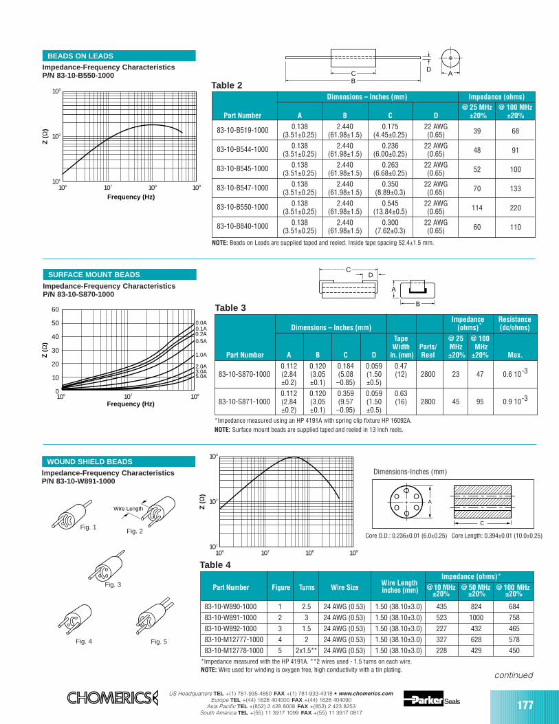
US Headquarters TEL +(1) 781-935-4850 FAX +(1) 781-933-4318 • www.chomerics.comEurope TEL +(44) 1628 404000 FAX +(44) 1628 404090
Asia Pacific TEL +(852) 2 428 8008 FAX +(852) 2 423 8253South America TEL +(55) 11 3917 1099 FAX +(55) 11 3917 0817
177
Wire LengthImpedance (ohms)*
Part Number Figure Turns Wire Size inches (mm) @ 10 MHz @ 50 MHz @ 100 MHz±20% ±20% ±20%
83-10-W890-1000 1 2.5 24 AWG (0.53) 1.50 (38.10±3.0) 435 824 68483-10-W891-1000 2 3 24 AWG (0.53) 1.50 (38.10±3.0) 523 1000 75883-10-W892-1000 3 1.5 24 AWG (0.53) 1.50 (38.10±3.0) 227 432 46583-10-M12777-1000 4 2 24 AWG (0.53) 1.50 (38.10±3.0) 327 628 57883-10-M12778-1000 5 2x1.5** 24 AWG (0.53) 1.50 (38.10±3.0) 228 429 450
NOTE: Beads on Leads are supplied taped and reeled. Inside tape spacing 52.4±1.5 mm.
*Impedance measured using an HP 4191A with spring clip fixture HP 16092A.NOTE: Surface mount beads are supplied taped and reeled in 13 inch reels.
Dimensions – Inches (mm) Impedance (ohms)@ 25 MHz @ 100 MHz
Part Number A B C D ±20% ±20%
83-10-B519-1000 0.138 2.440 0.175 22 AWG(3.51±0.25) (61.98±1.5) (4.45±0.25) (0.65) 39 68
83-10-B544-1000 0.138 2.440 0.236 22 AWG(3.51±0.25) (61.98±1.5) (6.00±0.25) (0.65) 48 91
83-10-B545-1000 0.138 2.440 0.263 22 AWG(3.51±0.25) (61.98±1.5) (6.68±0.25) (0.65) 52 100
83-10-B547-1000 0.138 2.440 0.350 22 AWG(3.51±0.25) (61.98±1.5) (8.89±0.3) (0.65) 70 133
83-10-B550-1000 0.138 2.440 0.545 22 AWG(3.51±0.25) (61.98±1.5) (13.84±0.5) (0.65) 114 220
83-10-B840-1000 0.138 2.440 0.300 22 AWG(3.51±0.25) (61.98±1.5) (7.62±0.3) (0.65) 60 110
BEADS ON LEADS
SURFACE MOUNT BEADS
B
D C A
103
102
101
106 107 108 109
Z (
Ω)
Frequency (Hz)
Impedance ResistanceDimensions – Inches (mm) (ohms)* (dc/ohms)
Tape @ 25 @ 100Width Parts/ MHz MHz
Part Number A B C D in. (mm) Reel ±20% ±20% Max.
0.112 0.120 0.184 0.059 0.4783-10-S870-1000 (2.84 (3.05 (5.08 (1.50 (12) 2800 23 47 0.6 10-3
±0.2) ±0.1) –0.85) ±0.5)0.112 0.120 0.359 0.059 0.63
83-10-S871-1000 (2.84 (3.05 (9.57 (1.50 (16) 2800 45 95 0.9 10-3
±0.2) ±0.1) –0.95) ±0.5)
B
DC
A
0
10
20
30
40
50
60
106 108107
Z (
Ω)
Frequency (Hz)
0.0A0.1A0.2A0.5A
1.0A
2.0A3.0A5.0A
Impedance-Frequency CharacteristicsP/N 83-10-B550-1000
Impedance-Frequency CharacteristicsP/N 83-10-S870-1000
Table 2
Table 3
continued
103
102
101
106 107 108 109
Z (
Ω)
WOUND SHIELD BEADS
Impedance-Frequency CharacteristicsP/N 83-10-W891-1000
Wire Length
Fig. 1
Fig. 3
Fig. 2
Dimensions-Inches (mm)
Core O.D.: 0.236±0.01 (6.0±0.25) Core Length: 0.394±0.01 (10.0±0.25)
A
C
Table 4
*Impedance measured with the HP 4191A. **2 wires used - 1.5 turns on each wire.NOTE: Wire used for winding is oxygen free, high conductivity with a tin plating.
Fig. 5Fig. 4
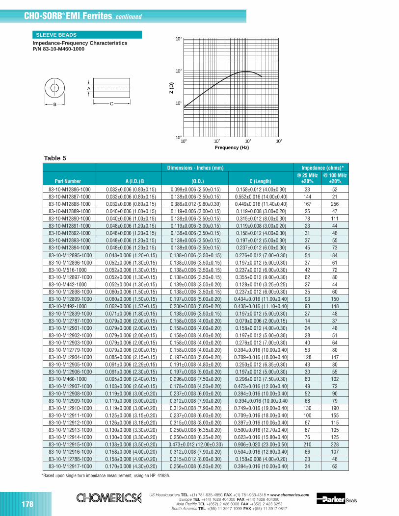
178US Headquarters TEL +(1) 781-935-4850 FAX +(1) 781-933-4318 • www.chomerics.com
Europe TEL +(44) 1628 404000 FAX +(44) 1628 404090Asia Pacific TEL +(852) 2 428 8008 FAX +(852) 2 423 8253
South America TEL +(55) 11 3917 1099 FAX +(55) 11 3917 0817
B
A
C
Z (
Ω)
103
102
101
100
106 107 108 109
Frequency (Hz)
SLEEVE BEADS
Impedance-Frequency CharacteristicsP/N 83-10-M460-1000
CHO-SORB® EMI Ferrites continued
*Based upon single turn impedance measurement, using an HP 4193A.
Table 5Dimensions - Inches (mm) Impedance (ohms)*
@ 25 MHz @ 100 MHz Part Number A (I.D.) B (O.D.) C (Length) ±20% ±20%
83-10-M12886-1000 0.032±0.006 (0.80±0.15) 0.098±0.006 (2.50±0.15) 0.158±0.012 (4.00±0.30) 33 5283-10-M12887-1000 0.032±0.006 (0.80±0.15) 0.138±0.006 (3.50±0.15) 0.552±0.016 (14.00±0.40) 144 2183-10-M12888-1000 0.032±0.006 (0.80±0.15) 0.386±0.012 (9.80±0.30) 0.449±0.016 (11.40±0.40) 167 25683-10-M12889-1000 0.040±0.006 (1.00±0.15) 0.119±0.006 (3.00±0.15) 0.119±0.008 (3.00±0.20) 25 4783-10-M12890-1000 0.040±0.006 (1.00±0.15) 0.138±0.006 (3.50±0.15) 0.315±0.012 (8.00±0.30) 78 11183-10-M12891-1000 0.048±0.006 (1.20±0.15) 0.119±0.006 (3.00±0.15) 0.119±0.008 (3.00±0.20) 23 4483-10-M12892-1000 0.048±0.006 (1.20±0.15) 0.138±0.006 (3.50±0.15) 0.158±0.012 (4.00±0.30) 31 4683-10-M12893-1000 0.048±0.006 (1.20±0.15) 0.138±0.006 (3.50±0.15) 0.197±0.012 (5.00±0.30) 37 5583-10-M12894-1000 0.048±0.006 (1.20±0.15) 0.138±0.006 (3.50±0.15) 0.237±0.012 (6.00±0.30) 45 7383-10-M12895-1000 0.048±0.006 (1.20±0.15) 0.138±0.006 (3.50±0.15) 0.276±0.012 (7.00±0.30) 54 8483-10-M12896-1000 0.052±0.006 (1.30±0.15) 0.138±0.006 (3.50±0.15) 0.197±0.012 (5.00±0.30) 37 6183-10-M516-1000 0.052±0.006 (1.30±0.15) 0.138±0.006 (3.50±0.15) 0.237±0.012 (6.00±0.30) 42 7283-10-M12897-1000 0.052±0.006 (1.30±0.15) 0.138±0.006 (3.50±0.15) 0.355±0.012 (9.00±0.30) 62 8083-10-M442-1000 0.052±0.004 (1.30±0.15) 0.139±0.008 (3.50±0.20) 0.128±0.010 (3.25±0.25) 27 4483-10-M12898-1000 0.060±0.006 (1.50±0.15) 0.138±0.006 (3.50±0.15) 0.237±0.012 (6.00±0.30) 35 6083-10-M12899-1000 0.060±0.006 (1.50±0.15) 0.197±0.008 (5.00±0.20) 0.434±0.016 (11.00±0.40) 93 15083-10-M492-1000 0.062±0.006 (1.57±0.15) 0.200±0.008 (5.00±0.20) 0.438±0.016 (11.10±0.40) 93 14883-10-M12839-1000 0.071±0.006 (1.80±0.15) 0.138±0.006 (3.50±0.15) 0.197±0.012 (5.00±0.30) 27 4883-10-M12787-1000 0.079±0.006 (2.00±0.15) 0.158±0.008 (4.00±0.20) 0.079±0.006 (2.00±0.15) 14 3783-10-M12901-1000 0.079±0.006 (2.00±0.15) 0.158±0.008 (4.00±0.20) 0.158±0.012 (4.00±0.30) 24 4883-10-M12902-1000 0.079±0.006 (2.00±0.15) 0.158±0.008 (4.00±0.20) 0.197±0.012 (5.00±0.30) 28 5183-10-M12903-1000 0.079±0.006 (2.00±0.15) 0.158±0.008 (4.00±0.20) 0.276±0.012 (7.00±0.30) 40 6483-10-M12779-1000 0.079±0.006 (2.00±0.15) 0.158±0.008 (4.00±0.20) 0.394±0.016 (10.00±0.40) 53 8083-10-M12904-1000 0.085±0.006 (2.15±0.15) 0.197±0.008 (5.00±0.20) 0.709±0.016 (18.00±0.40) 128 14783-10-M12905-1000 0.091±0.006 (2.29±0.15) 0.191±0.008 (4.80±0.20) 0.250±0.012 (6.35±0.30) 43 8083-10-M12906-1000 0.091±0.006 (2.30±0.15) 0.197±0.008 (5.00±0.20) 0.197±0.012 (5.00±0.30) 30 5583-10-M460-1000 0.095±0.006 (2.40±0.15) 0.296±0.008 (7.50±0.20) 0.296±0.012 (7.50±0.30) 60 10283-10-M12907-1000 0.103±0.006 (2.60±0.15) 0.178±0.008 (4.50±0.20) 0.473±0.016 (12.00±0.40) 49 7283-10-M12908-1000 0.119±0.008 (3.00±0.20) 0.237±0.008 (6.00±0.20) 0.394±0.016 (10.00±0.40) 52 9083-10-M12909-1000 0.119±0.008 (3.00±0.20) 0.312±0.008 (7.90±0.20) 0.394±0.016 (10.00±0.40 68 7983-10-M12910-1000 0.119±0.008 (3.00±0.20) 0.312±0.008 (7.90±0.20) 0.749±0.016 (19.00±0.40) 130 19083-10-M12911-1000 0.125±0.008 (3.15±0.20) 0.237±0.008 (6.00±0.20) 0.709±0.016 (18.00±0.40) 100 15583-10-M12912-1000 0.126±0.008 (3.18±0.20) 0.315±0.008 (8.00±0.20) 0.397±0.016 (10.06±0.40) 67 11583-10-M12913-1000 0.130±0.008 (3.30±0.20) 0.250±0.008 (6.35±0.20) 0.500±0.016 (12.70±0.40) 67 10583-10-M12914-1000 0.130±0.008 (3.30±0.20) 0.250±0.008 (6.35±0.20) 0.623±0.016 (15.80±0.40) 76 12583-10-M12915-1000 0.138±0.008 (3.50±0.20) 0.473±0.012 (12.00±0.30) 0.906±0.020 (23.00±0.50) 210 32883-10-M12916-1000 0.158±0.008 (4.00±0.20) 0.312±0.008 (7.90±0.20) 0.504±0.016 (12.80±0.40) 66 10783-10-M12788-1000 0.158±0.008 (4.00±0.20) 0.315±0.012 (8.00±0.30) 0.158±0.008 (4.00±0.20) 23 4683-10-M12917-1000 0.170±0.008 (4.30±0.20) 0.256±0.008 (6.50±0.20) 0.394±0.016 (10.00±0.40) 34 62
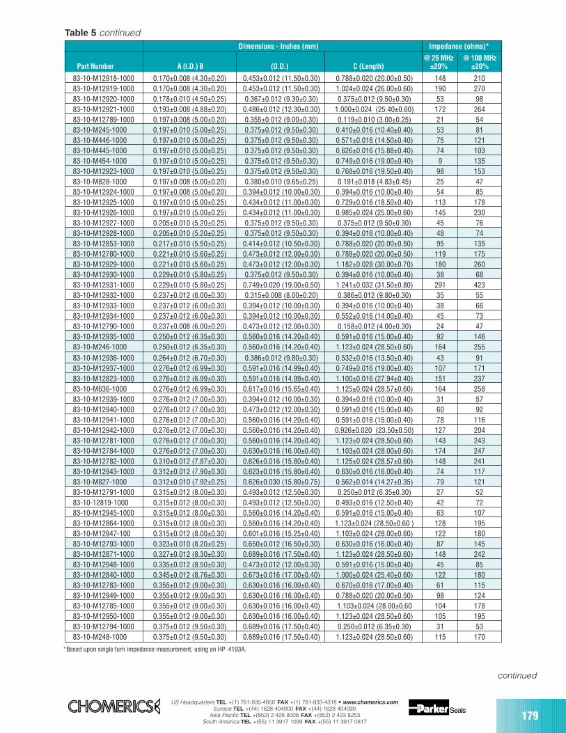
US Headquarters TEL +(1) 781-935-4850 FAX +(1) 781-933-4318 • www.chomerics.comEurope TEL +(44) 1628 404000 FAX +(44) 1628 404090
Asia Pacific TEL +(852) 2 428 8008 FAX +(852) 2 423 8253South America TEL +(55) 11 3917 1099 FAX +(55) 11 3917 0817
179
continued
Dimensions - Inches (mm) Impedance (ohms)*
@ 25 MHz @ 100 MHz Part Number A (I.D.) B (O.D.) C (Length) ±20% ±20%
*Based upon single turn impedance measurement, using an HP 4193A.
Table 5 continued
83-10-M12918-1000 0.170±0.008 (4.30±0.20) 0.453±0.012 (11.50±0.30) 0.788±0.020 (20.00±0.50) 148 21083-10-M12919-1000 0.170±0.008 (4.30±0.20) 0.453±0.012 (11.50±0.30) 1.024±0.024 (26.00±0.60) 190 27083-10-M12920-1000 0.178±0.010 (4.50±0.25) 0.367±0.012 (9.30±0.30) 0.375±0.012 (9.50±0.30) 53 9883-10-M12921-1000 0.193±0.008 (4.88±0.20) 0.486±0.012 (12.30±0.30) 1.000±0.024 (25.40±0.60) 172 26483-10-M12789-1000 0.197±0.008 (5.00±0.20) 0.355±0.012 (9.00±0.30) 0.119±0.010 (3.00±0.25) 21 5483-10-M245-1000 0.197±0.010 (5.00±0.25) 0.375±0.012 (9.50±0.30) 0.410±0.016 (10.40±0.40) 53 8183-10-M446-1000 0.197±0.010 (5.00±0.25) 0.375±0.012 (9.50±0.30) 0.571±0.016 (14.50±0.40) 75 12183-10-M445-1000 0.197±0.010 (5.00±0.25) 0.375±0.012 (9.50±0.30) 0.626±0.016 (15.88±0.40) 74 10383-10-M454-1000 0.197±0.010 (5.00±0.25) 0.375±0.012 (9.50±0.30) 0.749±0.016 (19.00±0.40) 9 13583-10-M12923-1000 0.197±0.010 (5.00±0.25) 0.375±0.012 (9.50±0.30) 0.768±0.016 (19.50±0.40) 98 15383-10-M828-1000 0.197±0.008 (5.00±0.20) 0.380±0.010 (9.65±0.25) 0.191±0.018 (4.83±0.45) 25 4783-10-M12924-1000 0.197±0.008 (5.00±0.20) 0.394±0.012 (10.00±0.30) 0.394±0.016 (10.00±0.40) 54 8583-10-M12925-1000 0.197±0.010 (5.00±0.25) 0.434±0.012 (11.00±0.30) 0.729±0.016 (18.50±0.40) 113 17883-10-M12926-1000 0.197±0.010 (5.00±0.25) 0.434±0.012 (11.00±0.30) 0.985±0.024 (25.00±0.60) 145 23083-10-M12927-1000 0.205±0.010 (5.20±0.25) 0.375±0.012 (9.50±0.30) 0.375±0.012 (9.50±0.30) 45 7683-10-M12928-1000 0.205±0.010 (5.20±0.25) 0.375±0.012 (9.50±0.30) 0.394±0.016 (10.00±0.40) 48 7483-10-M12853-1000 0.217±0.010 (5.50±0.25) 0.414±0.012 (10.50±0.30) 0.788±0.020 (20.00±0.50) 95 13583-10-M12780-1000 0.221±0.010 (5.60±0.25) 0.473±0.012 (12.00±0.30) 0.788±0.020 (20.00±0.50) 119 17583-10-M12929-1000 0.221±0.010 (5.60±0.25) 0.473±0.012 (12.00±0.30) 1.182±0.028 (30.00±0.70) 180 26083-10-M12930-1000 0.229±0.010 (5.80±0.25) 0.375±0.012 (9.50±0.30) 0.394±0.016 (10.00±0.40) 38 6883-10-M12931-1000 0.229±0.010 (5.80±0.25) 0.749±0.020 (19.00±0.50) 1.241±0.032 (31.50±0.80) 291 42383-10-M12932-1000 0.237±0.012 (6.00±0.30) 0.315±0.008 (8.00±0.20) 0.386±0.012 (9.80±0.30) 35 5583-10-M12933-1000 0.237±0.012 (6.00±0.30) 0.394±0.012 (10.00±0.30) 0.394±0.016 (10.00±0.40) 38 6683-10-M12934-1000 0.237±0.012 (6.00±0.30) 0.394±0.012 (10.00±0.30) 0.552±0.016 (14.00±0.40) 45 7383-10-M12790-1000 0.237±0.008 (6.00±0.20) 0.473±0.012 (12.00±0.30) 0.158±0.012 (4.00±0.30) 24 4783-10-M12935-1000 0.250±0.012 (6.35±0.30) 0.560±0.016 (14.20±0.40) 0.591±0.016 (15.00±0.40) 92 14683-10-M246-1000 0.250±0.012 (6.35±0.30) 0.560±0.016 (14.20±0.40) 1.123±0.024 (28.50±0.60) 164 25583-10-M12936-1000 0.264±0.012 (6.70±0.30) 0.386±0.012 (9.80±0.30) 0.532±0.016 (13.50±0.40) 43 9183-10-M12937-1000 0.276±0.012 (6.99±0.30) 0.591±0.016 (14.99±0.40) 0.749±0.016 (19.00±0.40) 107 17183-10-M12823-1000 0.276±0.012 (6.99±0.30) 0.591±0.016 (14.99±0.40) 1.100±0.016 (27.94±0.40) 151 23783-10-M636-1000 0.276±0.012 (6.99±0.30) 0.617±0.016 (15.65±0.40) 1.125±0.024 (28.57±0.60) 164 25883-10-M12939-1000 0.276±0.012 (7.00±0.30) 0.394±0.012 (10.00±0.30) 0.394±0.016 (10.00±0.40) 31 5783-10-M12940-1000 0.276±0.012 (7.00±0.30) 0.473±0.012 (12.00±0.30) 0.591±0.016 (15.00±0.40) 60 9283-10-M12941-1000 0.276±0.012 (7.00±0.30) 0.560±0.016 (14.20±0.40) 0.591±0.016 (15.00±0.40) 78 11683-10-M12942-1000 0.276±0.012 (7.00±0.30) 0.560±0.016 (14.20±0.40) 0.926±0.020 (23.50±0.50) 127 20483-10-M12781-1000 0.276±0.012 (7.00±0.30) 0.560±0.016 (14.20±0.40) 1.123±0.024 (28.50±0.60) 143 24383-10-M12784-1000 0.276±0.012 (7.00±0.30) 0.630±0.016 (16.00±0.40) 1.103±0.024 (28.00±0.60) 174 24783-10-M12782-1000 0.310±0.012 (7.87±0.30) 0.626±0.016 (15.80±0.40) 1.125±0.024 (28.57±0.60) 148 24183-10-M12943-1000 0.312±0.012 (7.90±0.30) 0.623±0.016 (15.80±0.40) 0.630±0.016 (16.00±0.40) 74 11783-10-M827-1000 0.312±0.010 (7.92±0.25) 0.626±0.030 (15.80±0.75) 0.562±0.014 (14.27±0.35) 79 12183-10-M12791-1000 0.315±0.012 (8.00±0.30) 0.493±0.012 (12.50±0.30) 0.250±0.012 (6.35±0.30) 27 5283-10-12819-1000 0.315±0.012 (8.00±0.30) 0.493±0.012 (12.50±0.30) 0.493±0.016 (12.50±0.40) 42 7283-10-M12945-1000 0.315±0.012 (8.00±0.30) 0.560±0.016 (14.20±0.40) 0.591±0.016 (15.00±0.40) 63 10783-10-M12864-1000 0.315±0.012 (8.00±0.30) 0.560±0.016 (14.20±0.40) 1.123±0.024 (28.50±0.60 ) 128 19583-10-M12947-100 0.315±0.012 (8.00±0.30) 0.601±0.016 (15.25±0.40) 1.103±0.024 (28.00±0.60) 122 18083-10-M12793-1000 0.323±0.010 (8.20±0.25) 0.650±0.012 (16.50±0.30) 0.630±0.016 (16.00±0.40) 87 14583-10-M12871-1000 0.327±0.012 (8.30±0.30) 0.689±0.016 (17.50±0.40) 1.123±0.024 (28.50±0.60) 148 24283-10-M12948-1000 0.335±0.012 (8.50±0.30) 0.473±0.012 (12.00±0.30) 0.591±0.016 (15.00±0.40) 45 8583-10-M12840-1000 0.345±0.012 (8.76±0.30) 0.673±0.016 (17.00±0.40) 1.000±0.024 (25.40±0.60) 122 18083-10-M12783-1000 0.355±0.012 (9.00±0.30) 0.630±0.016 (16.00±0.40) 0.670±0.016 (17.00±0.40) 61 11583-10-M12949-1000 0.355±0.012 (9.00±0.30) 0.630±0.016 (16.00±0.40) 0.788±0.020 (20.00±0.50) 98 12483-10-M12785-1000 0.355±0.012 (9.00±0.30) 0.630±0.016 (16.00±0.40) 1.103±0.024 (28.00±0.60 104 17883-10-M12950-1000 0.355±0.012 (9.00±0.30) 0.630±0.016 (16.00±0.40) 1.123±0.024 (28.50±0.60) 105 19583-10-M12794-1000 0.375±0.012 (9.50±0.30) 0.689±0.016 (17.50±0.40) 0.250±0.012 (6.35±0.30) 31 5383-10-M248-1000 0.375±0.012 (9.50±0.30) 0.689±0.016 (17.50±0.40) 1.123±0.024 (28.50±0.60) 115 170
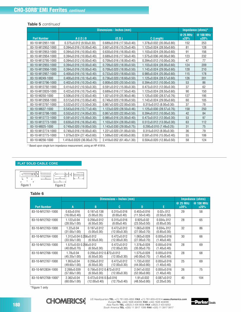
180US Headquarters TEL +(1) 781-935-4850 FAX +(1) 781-933-4318 • www.chomerics.com
Europe TEL +(44) 1628 404000 FAX +(44) 1628 404090Asia Pacific TEL +(852) 2 428 8008 FAX +(852) 2 423 8253
South America TEL +(55) 11 3917 1099 FAX +(55) 11 3917 0817
Table 6
CHO-SORB® EMI Ferrites continued
FLAT SOLID CABLE CORE
Figure 1 Figure 2
Dimensions – Inches (mm) Impedance (ohms)@ 25 MHz @ 100 MHz
Part Number A B C D E ±20% ±20%
83-10-M12761-1000 0.63±0.016 0.197±0.138 0.315±0.016 0.453±0.016 0.02±.012 29 58(16.00±0.40) (5.00±0.35) (8.00±0.40) (11.50+0.40) (0.50±0.30)
83-10-M12762-1000 1.122±0.04 0.256±0.012 0.315±0.016 0.925±0.02 0.034±.012 28 65(28.50±1.00) (6.50±0.30) (8.00±0.40) (23.50±0.50) (0.85±0.30)
83-10-M12763-1000 1.22±0.04 0.197±0.012 0.472±0.012 1.063±0.028 0.034±.012 32 86(31.00±1.00) (5.00±0.30) (12.00±0.30) (27.00±0.70) (0.85±0.30)
83-10-M12764-1000 1.312±0.04 0.256±0.012 0.472±0.012 1.063±0.028 0.055±0.016 30 66(33.50±1.00) (6.50±0.30) (12.00±0.30) (27.00±0.70) (1.40±0.40)
83-10-M12765-1000 1.575±0.03 0.256±0.012 0.472±0.012 1.378±0.028 0.055±0.016 28 69(40.00±0.70) (6.50±0.30) (12.00±0.30) (35.00±0.70) (1.40±0.40)
83-10-M12766-1000 1.78±0.04 0.256±0.012 0.472±0.012 1.575±0.028 0.055±0.016 28 68(45.20±1.00) (6.50±0.30) (12.00±0.30) (40.00±0.70) (1.40±0.40)
83-10-M12767-1000 1.953±0.04 0.256±0.012 0.472±0.012 1.732±0.032 0.055±0.016 25 69(49.60±1.00) (6.50±0.30) (12.00±0.30) (44.00±0.80) (1.40±0.40)
83-10-M12834-1000 2.268±0.039 0.756±0.012 0.472±0.012 2.047±0.032 0.055±0.016 26 75(57.60±1.00) (6.50±0.30) (12.00±0.30) (52.00±0.80) (1.40±0.40)
83-10-M12768-1000* 2.362±0.04 0.472±0.016 0.5±0.016 1.91±0.032 0.087±0.012 40 104(60.00±1.00) (12.00±0.40) (12.70±0.40) (48.50±0.80) (2.20±0.30)
*Figure 1 only
83-10-M12951-100 0.375±0.012 (9.50±0.30) 0.689±0.016 (17.50±0.40) 1.378±0.032 (35.00±0.80) 152 25383-10-M12952-1000 0.394±0.016 (10.00±0.40) 0.601±0.016 (15.25±0.40) 1.123±0.024 (28.50±0.60) 81 12883-10-M12953-1000 0.394±0.016 (10.00±0.40) 0.630±0.016 (16.00±0.40) 1.103±0.024 (28.00±0.60) 91 15683-10-M12954-1000 0.394±0.016 (10.00±0.40) 0.689±0.016 (17.50±0.40) 1.575±0.036 (40.00±0.90) 123 23283-10-M12795-1000 0.394±0.012 (10.00±0.40) 0.709±0.016 (18.00±0.40) 0.394±0.012 (10.00±0.30) 47 7783-10-M12955-1000 0.394±0.016 (10.00±0.40) 0.709±0.020 (18.00±0.50) 1.103±0.024 (28.00±0.60) 124 20983-10-M12956-1000 0.394±0.016 (10.00±0.40) 0.709±0.020 (18.00±0.50) 1.142±0.024 (29.00±0.60) 128 21083-10-M12957-1000 0.400±0.016 (10.16±0.40) 0.733±0.020 (18.60±0.50) 0.985±0.024 (25.00±0.60) 115 17883-10-M249-1000 0.400±0.016 (10.16±0.40) 0.736±0.020 (18.60±0.50) 1.125±0.024 (28.57±0.60) 126 20183-10-M12796-1000 0.402±0.016 (10.20±0.40) 0.808±0.020 (20.50±0.50) 0.394±0.012 (10.00±0.30) 53 8683-10-M12792-1000 0.414±0.012 (10.50±0.30) 0.591±0.012 (15.00±0.30) 0.473±0.012 (12.00±0.30) 37 6283-10-M12820-1000 0.422±0.016 (10.70±0.40) 0.689±0.016 (17.50±0.40) 1.123±0.024 (28.50±0.60) 90 15083-10-M250-1000 0.506±0.016 (12.83±0.40) 1.021±0.019 (25.90±0.46) 1.125±0.030 (28.57±0.76) 127 19583-10-M12958-1000 0.512±0.016 (13.00±0.40) 0.749±0.020 (19.00±0.50) 1.142±0.024 (29.00±0.60) 60 10583-10-M12797-1000 0.532±0.012 (13.50±0.30) 0.867±0.020 (22.00±0.50) 0.315±0.012 (8.00±0.30) 37 7883-10-M637-1000 0.543±0.016 (13.77±0.40) 1.123±0.020 (28.50±0.46) 1.125±0.030 (28.57±0.76) 158 25083-10-M12798-1000 0.552±0.012 (14.00±0.30) 0.867±0.020 (22.00±0.50) 0.394±0.012 (10.00±0.30) 42 8483-10-M12772-1000 0.591±0.012 (15.00±0.30) 0.985±0.016 (25.00±0.40) 0.473±0.012 (12.00±0.30) 53 9783-10-M12773-1000 0.630±0.016 (16.00±0.40) 1.103±0.024 (28.00±0.60) 0.512±0.012 (13.00±0.30) 63 11283-10-M825-1000 0.749±0.020 (19.00±0.50) 1.143±0.030 (29.00±0.75) 0.295±0.010 (7.49±0.25) 31 7583-10-M12774-1000 0.749±0.016 (19.00±0.40) 1.221±0.020 (31.00±0.50) 0.315±0.012 (8.00±0.30) 36 7983-10-M12775-1000 1.079±0.024 (27.40±0.60) 1.599±0.032 (40.60±0.80) 0.591±0.016 (15.00±0.40) 55 10683-10-M256-1000 1.418±0.0320 (36.00±0.75) 2.418±0.052 (61.40±1.30) 0.504±0.020 (12.80±0.50) 58 124
Dimensions - Inches (mm) Impedance (ohms)*
@ 25 MHz @ 100 MHz Part Number A (I.D.) B (O.D.) C (Length) ±20% ±20%
Table 5 continued
* Based upon single turn impedance measurement, using an HP 4191A.
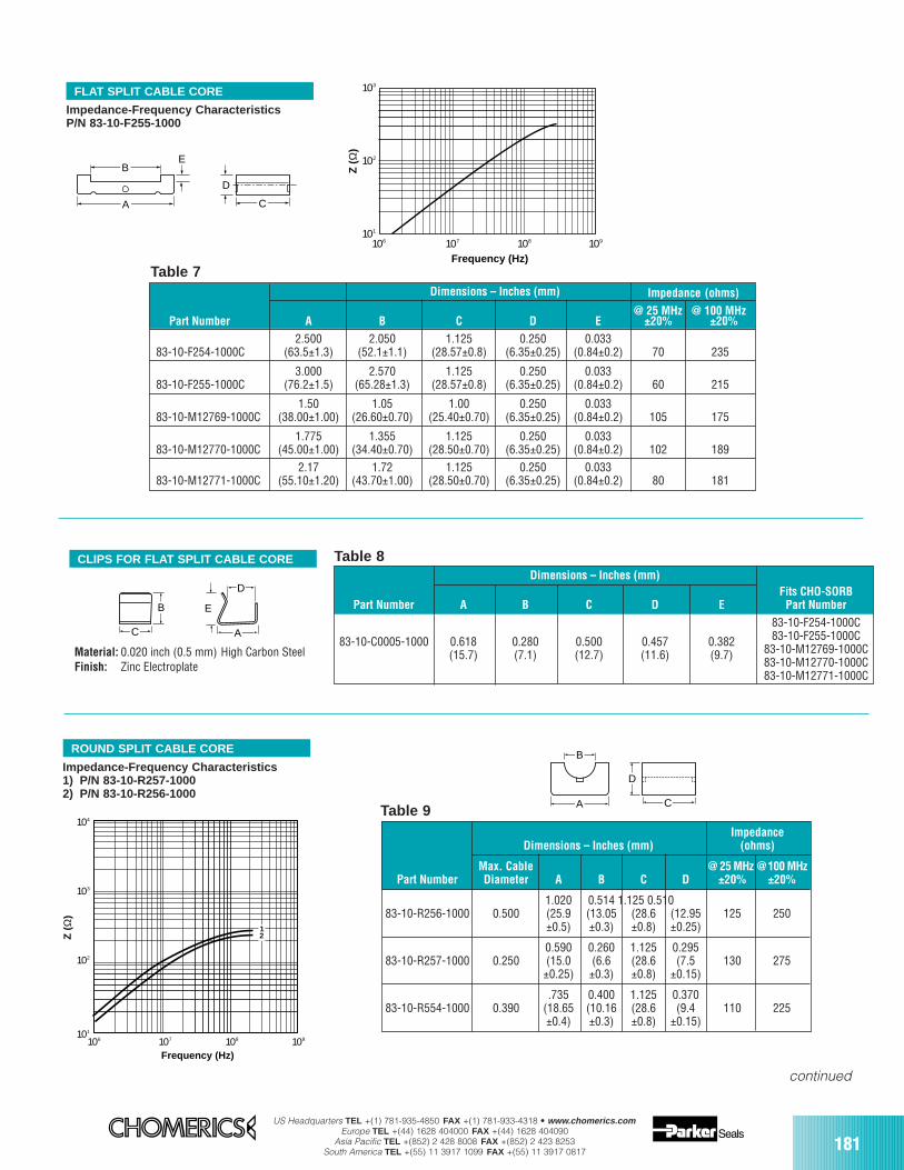
US Headquarters TEL +(1) 781-935-4850 FAX +(1) 781-933-4318 • www.chomerics.comEurope TEL +(44) 1628 404000 FAX +(44) 1628 404090
Asia Pacific TEL +(852) 2 428 8008 FAX +(852) 2 423 8253South America TEL +(55) 11 3917 1099 FAX +(55) 11 3917 0817 181
C A
B E
D
CLIPS FOR FLAT SPLIT CABLE CORE
103
102
101
106 107 108 109
Z (
Ω)
Frequency (Hz)
D
E
A
B
C
FLAT SPLIT CABLE CORE
Impedance-Frequency CharacteristicsP/N 83-10-F255-1000
Material: 0.020 inch (0.5 mm) High Carbon SteelFinish: Zinc Electroplate
Table 7
Table 8
Dimensions – Inches (mm) Impedance (ohms)
@ 25 MHz @ 100 MHzPart Number A B C D E ±20% ±20%
2.500 2.050 1.125 0.250 0.03383-10-F254-1000C (63.5±1.3) (52.1±1.1) (28.57±0.8) (6.35±0.25) (0.84±0.2) 70 235
3.000 2.570 1.125 0.250 0.03383-10-F255-1000C (76.2±1.5) (65.28±1.3) (28.57±0.8) (6.35±0.25) (0.84±0.2) 60 215
1.50 1.05 1.00 0.250 0.03383-10-M12769-1000C (38.00±1.00) (26.60±0.70) (25.40±0.70) (6.35±0.25) (0.84±0.2) 105 175
1.775 1.355 1.125 0.250 0.03383-10-M12770-1000C (45.00±1.00) (34.40±0.70) (28.50±0.70) (6.35±0.25) (0.84±0.2) 102 189
2.17 1.72 1.125 0.250 0.03383-10-M12771-1000C (55.10±1.20) (43.70±1.00) (28.50±0.70) (6.35±0.25) (0.84±0.2) 80 181
ROUND SPLIT CABLE CORE
Z (
Ω)
104
103
102
101
106 107 108 109
Frequency (Hz)
12
Impedance-Frequency Characteristics1) P/N 83-10-R257-10002) P/N 83-10-R256-1000
D
C
B
ATable 9Impedance
Dimensions – Inches (mm) (ohms)
Max. Cable @ 25 MHz @100 MHzPart Number Diameter A B C D ±20% ±20%
1.020 0.514 1.125 0.510 83-10-R256-1000 0.500 (25.9 (13.05 (28.6 (12.95 125 250
±0.5) ±0.3) ±0.8) ±0.25)
0.590 0.260 1.125 0.29583-10-R257-1000 0.250 (15.0 (6.6 (28.6 (7.5 130 275
±0.25) ±0.3) ±0.8) ±0.15)
.735 0.400 1.125 0.37083-10-R554-1000 0.390 (18.65 (10.16 (28.6 (9.4 110 225
±0.4) ±0.3) ±0.8) ±0.15)
continued
Dimensions – Inches (mm)Fits CHO-SORB
Part Number A B C D E Part Number
83-10-F254-1000C
83-10-C0005-1000 0.618 0.280 0.500 0.457 0.382 83-10-F255-1000C
(15.7) (7.1) (12.7) (11.6) (9.7) 83-10-M12769-1000C83-10-M12770-1000C83-10-M12771-1000C
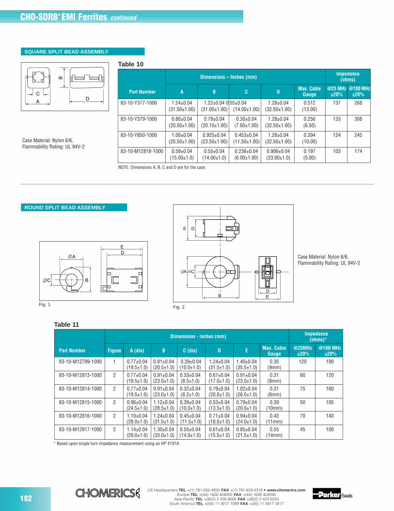
182US Headquarters TEL +(1) 781-935-4850 FAX +(1) 781-933-4318 • www.chomerics.com
Europe TEL +(44) 1628 404000 FAX +(44) 1628 404090Asia Pacific TEL +(852) 2 428 8008 FAX +(852) 2 423 8253
South America TEL +(55) 11 3917 1099 FAX +(55) 11 3917 0817
SQUARE SPLIT BEAD ASSEMBLY
Case Material: Nylon 6/6,Flammability Rating: UL 94V-2
Table 10
CHO-SORB® EMI Ferrites continued
ImpedanceDimensions – Inches (mm) (ohms)
Max. Cable @25 MHz @100 MHzPart Number A B C D Gauge ±20% ±20%
83-10-Y377-1000 1.24±0.04 1.22±0.04 0.55±0.04 1.28±0.04 0.512 137 268(31.50±1.00) (31.00±1.00) (14.00±1.00) (32.50±1.00) (13.00)
83-10-Y379-1000 0.80±0.04 0.79±0.04 0.30±0.04 1.28±0.04 0.256 133 308(20.50±1.00) (20.10±1.00) (7.60±1.00) (32.50±1.00) (6.50)
83-10-Y850-1000 1.00±0.04 0.925±0.04 0.453±0.04 1.28±0.04 0.394 124 245(25.50±1.00) (23.50±1.00) (11.50±1.00) (32.50±1.00) (10.00)
83-10-M12818-1000 0.59±0.04 0.55±0.04 0.236±0.04 0.906±0.04 0.197 103 174(15.00±1.0) (14.00±1.0) (6.00±1.00) (23.00±1.0) (5.00)
NOTE: Dimensions A, B, C and D are for the case.
ROUND SPLIT BEAD ASSEMBLY
Fig. 1
E
C
BDE
A
D
Fig. 2
Table 11
Case Material: Nylon 6/6,Flammability Rating: UL 94V-2
ImpedanceDimensions - inches (mm)(ohms)*
Part Number Figure A (dia) B C (dia) D E Max. Cable @25MHz @100 MHzGauge ±20% ±20%
83-10-M12799-1000 1 0.77±0.04 0.81±0.04 0.39±0.04 1.24±0.04 1.40±0.04 0.35 120 190(19.5±1.0) (20.5±1.0) (10.0±1.0) (31.5±1.0) (35.5±1.0) (9mm)
83-10-M12813-1000 2 0.77±0.04 0.91±0.04 0.33±0.04 0.67±0.04 0.91±0.04 0.31 60 120(19.5±1.0) (23.0±1.0) (8.5±1.0) (17.0±1.0) (23.0±1.0) (8mm)
83-10-M12814-1000 2 0.77±0.04 0.91±0.04 0.32±0.04 0.79±0.04 1.02±0.04 0.31 75 160(19.5±1.0) (23.0±1.0) (8.2±1.0) (20.0±1.0) (26.0±1.0) (8mm)
83-10-M12815-1000 2 0.96±0.04 1.12±0.04 0.39±0.04 0.53±0.04 0.79±0.04 0.39 50 105(24.5±1.0) (28.5±1.0) (10.0±1.0) (13.5±1.0) (20.0±1.0) (10mm)
83-10-M12816-1000 2 1.10±0.04 1.24±0.04 0.45±0.04 0.71±0.04 0.94±0.04 0.43 70 140(28.0±1.0) (31.5±1.0) (11.5±1.0) (18.0±1.0) (24.0±1.0) (11mm)
83-10-M12817-1000 2 1.14±0.04 1.30±0.04 0.55±0.04 0.61±0.04 0.85±0.04 0.55 45 100(29.0±1.0) (33.0±1.0) (14.0±1.0) (15.5±1.0) (21.5±1.0) (14mm)
* Based upon single turn impedance measurement using an HP 4191A
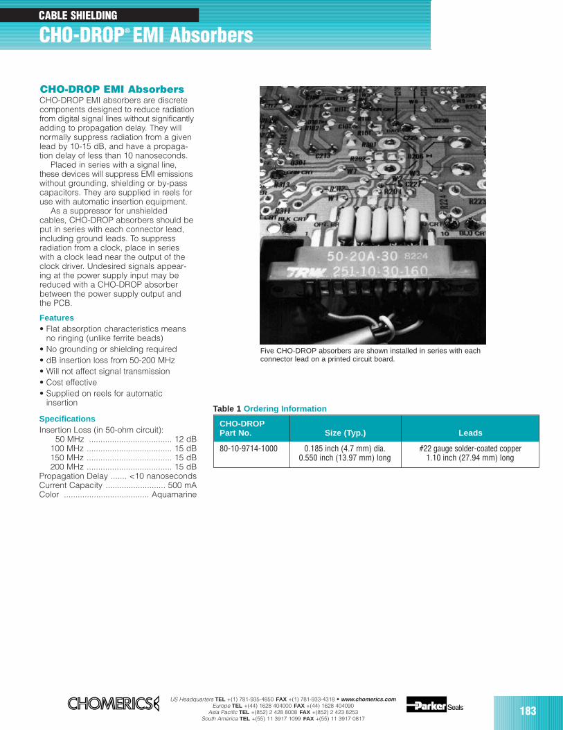
US Headquarters TEL +(1) 781-935-4850 FAX +(1) 781-933-4318 • www.chomerics.comEurope TEL +(44) 1628 404000 FAX +(44) 1628 404090
Asia Pacific TEL +(852) 2 428 8008 FAX +(852) 2 423 8253South America TEL +(55) 11 3917 1099 FAX +(55) 11 3917 0817
183
CABLE SHIELDING
CHO-DROP® EMI Absorbers
CHO-DROP EMI absorbers are discretecomponents designed to reduce radiationfrom digital signal lines without significantlyadding to propagation delay. They willnormally suppress radiation from a givenlead by 10-15 dB, and have a propaga-tion delay of less than 10 nanoseconds.
Placed in series with a signal line,these devices will suppress EMI emissionswithout grounding, shielding or by-passcapacitors. They are supplied in reels foruse with automatic insertion equipment.
As a suppressor for unshieldedcables, CHO-DROP absorbers should beput in series with each connector lead,including ground leads. To suppressradiation from a clock, place in serieswith a clock lead near the output of theclock driver. Undesired signals appear-ing at the power supply input may bereduced with a CHO-DROP absorberbetween the power supply output andthe PCB.
Features• Flat absorption characteristics means
no ringing (unlike ferrite beads)• No grounding or shielding required• dB insertion loss from 50-200 MHz• Will not affect signal transmission• Cost effective• Supplied on reels for automatic
insertion
SpecificationsInsertion Loss (in 50-ohm circuit):
50 MHz .................................... 12 dB100 MHz ..................................... 15 dB150 MHz ..................................... 15 dB200 MHz ..................................... 15 dB
Propagation Delay ....... <10 nanosecondsCurrent Capacity .......................... 500 mAColor ..................................... Aquamarine
CHO-DROPPart No. Size (Typ.) Leads
80-10-9714-1000 0.185 inch (4.7 mm) dia. #22 gauge solder-coated copper0.550 inch (13.97 mm) long 1.10 inch (27.94 mm) long
Table 1 Ordering Information
Five CHO-DROP absorbers are shown installed in series with eachconnector lead on a printed circuit board.
CHO-DROP EMI Absorbers
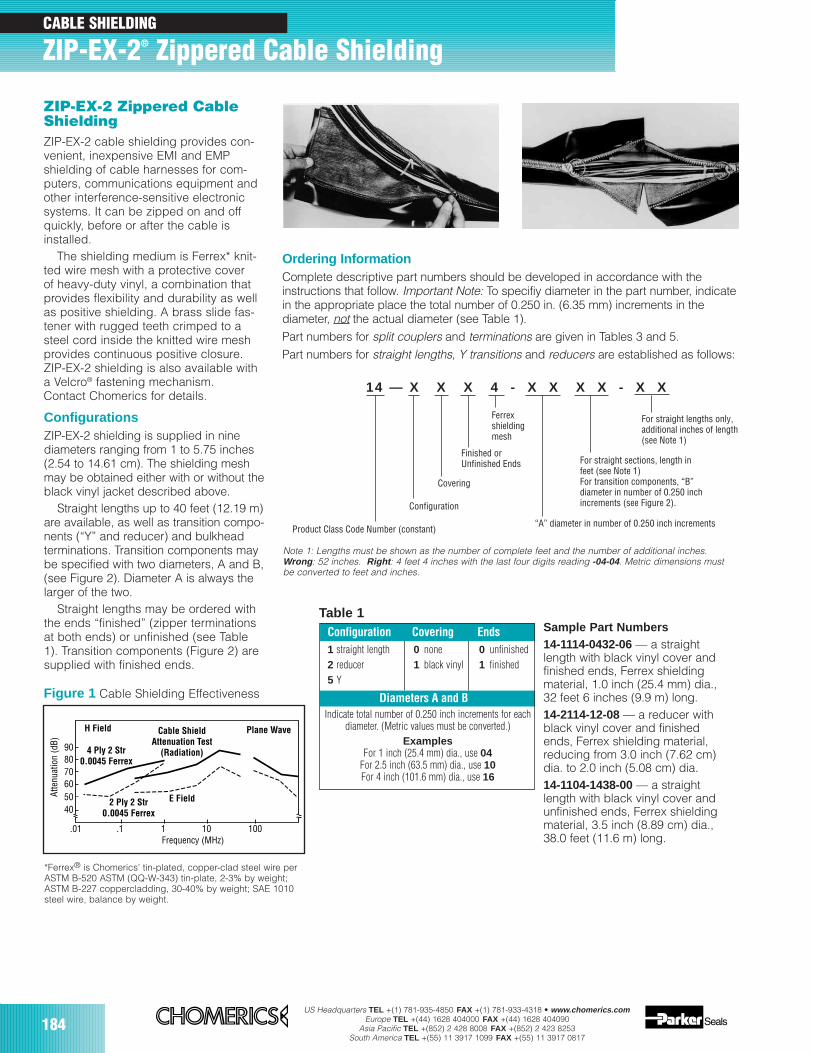
184US Headquarters TEL +(1) 781-935-4850 FAX +(1) 781-933-4318 • www.chomerics.com
Europe TEL +(44) 1628 404000 FAX +(44) 1628 404090Asia Pacific TEL +(852) 2 428 8008 FAX +(852) 2 423 8253
South America TEL +(55) 11 3917 1099 FAX +(55) 11 3917 0817
CABLE SHIELDING
ZIP-EX-2® Zippered Cable Shielding
Table 1Configuration Covering Ends1 straight length 0 none 0 unfinished2 reducer 1 black vinyl 1 finished5 Y
Diameters A and BIndicate total number of 0.250 inch increments for each
diameter. (Metric values must be converted.)Examples
For 1 inch (25.4 mm) dia., use 04For 2.5 inch (63.5 mm) dia., use 10For 4 inch (101.6 mm) dia., use 16
ZIP-EX-2 Zippered CableShieldingZIP-EX-2 cable shielding provides con-venient, inexpensive EMI and EMPshielding of cable harnesses for com-puters, communications equipment andother interference-sensitive electronicsystems. It can be zipped on and offquickly, before or after the cable isinstalled.
The shielding medium is Ferrex* knit-ted wire mesh with a protective coverof heavy-duty vinyl, a combination thatprovides flexibility and durability as wellas positive shielding. A brass slide fas-tener with rugged teeth crimped to asteel cord inside the knitted wire meshprovides continuous positive closure.ZIP-EX-2 shielding is also available witha Velcro® fastening mechanism.Contact Chomerics for details.
ConfigurationsZIP-EX-2 shielding is supplied in ninediameters ranging from 1 to 5.75 inches(2.54 to 14.61 cm). The shielding meshmay be obtained either with or without theblack vinyl jacket described above.
Straight lengths up to 40 feet (12.19 m)are available, as well as transition compo-nents (“Y” and reducer) and bulkheadterminations. Transition components maybe specified with two diameters, A and B,(see Figure 2). Diameter A is always thelarger of the two.
Straight lengths may be ordered withthe ends “finished” (zipper terminationsat both ends) or unfinished (see Table1). Transition components (Figure 2) aresupplied with finished ends.
*Ferrex® is Chomerics’ tin-plated, copper-clad steel wire perASTM B-520 ASTM (QQ-W-343) tin-plate, 2-3% by weight;ASTM B-227 coppercladding, 30-40% by weight; SAE 1010steel wire, balance by weight.
Ordering InformationComplete descriptive part numbers should be developed in accordance with theinstructions that follow. Important Note: To specifiy diameter in the part number, indicatein the appropriate place the total number of 0.250 in. (6.35 mm) increments in thediameter, not the actual diameter (see Table 1).Part numbers for split couplers and terminations are given in Tables 3 and 5. Part numbers for straight lengths, Y transitions and reducers are established as follows:
Atte
nuat
ion
(dB)
Frequency (MHz)
H Field Cable ShieldAttenuation Test
(Radiation)
Plane Wave
E Field
4 Ply 2 Str0.0045 Ferrex
2 Ply 2 Str0.0045 Ferrex
100101.1.01
908070605040
Figure 1 Cable Shielding Effectiveness
Sample Part Numbers14-1114-0432-06 — a straightlength with black vinyl cover andfinished ends, Ferrex shieldingmaterial, 1.0 inch (25.4 mm) dia.,32 feet 6 inches (9.9 m) long.14-2114-12-08 — a reducer withblack vinyl cover and finishedends, Ferrex shielding material,reducing from 3.0 inch (7.62 cm)dia. to 2.0 inch (5.08 cm) dia.14-1104-1438-00 — a straightlength with black vinyl cover andunfinished ends, Ferrex shieldingmaterial, 3.5 inch (8.89 cm) dia.,38.0 feet (11.6 m) long.
14 — X X X 4 - X X X X - X X
Note 1: Lengths must be shown as the number of complete feet and the number of additional inches.Wrong : 52 inches. Right : 4 feet 4 inches with the last four digits reading -04-04. Metric dimensions must be converted to feet and inches.
For straight lengths only,additional inches of length(see Note 1)
Product Class Code Number (constant)
For straight sections, length infeet (see Note 1)For transition components, “B”diameter in number of 0.250 inchincrements (see Figure 2).
“A” diameter in number of 0.250 inch increments
Ferrexshieldingmesh
Finished orUnfinished Ends
Covering
Configuration
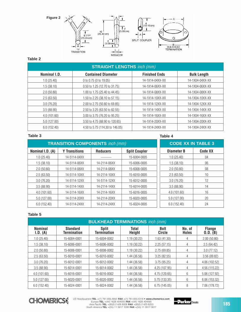
US Headquarters TEL +(1) 781-935-4850 FAX +(1) 781-933-4318 • www.chomerics.comEurope TEL +(44) 1628 404000 FAX +(44) 1628 404090
Asia Pacific TEL +(852) 2 428 8008 FAX +(852) 2 423 8253South America TEL +(55) 11 3917 1099 FAX +(55) 11 3917 0817
185
STRAIGHT LENGTHS inch (mm)
Nominal I.D. Contained Diameter Finished Ends Bulk Length1.0 (25.40) 0 to 0.75 (0 to 19.05) 14-1X14-04XX-XX 14-1X04-04XX-XX
1.5 (38.10) 0.50 to 1.25 (12.70 to 31.75) 14-1X14-06XX-XX 14-1X04-06XX-XX
2.0 (50.80) 1.00 to 1.75 (25.40 to 44.45) 14-1X14-08XX-XX 14-1X04-08XX-XX
2.5 (63.50) 1.50 to 2.25 (38.10 to 57.15) 14-1X14-10XX-XX 14-1X04-10XX-XX
3.0 (76.20) 2.00 to 2.75 (50.80 to 69.85) 14-1X14-12XX-XX 14-1X04-12XX-XX
3.5 (88.90) 2.50 to 3.25 (63.50 to 82.55) 14-1X14-14XX-XX 14-1X04-14XX-XX
4.0 (101.60) 3.00 to 3.75 (76.20 to 95.25) 14-1X14-16XX-XX 14-1X04-16XX-XX
5.0 (127.00) 3.50 to 4.75 (88.90 to 120.65) 14-1X14-20XX-XX 14-1X04-20XX-XX
6.0 (152.40) 4.50 to 5.75 (114.30 to 146.05) 14-1X14-24XX-XX 14-1X04-24XX-XX
TRANSITION COMPONENTS inch (mm)
Nominal I.D. (A) Y Transitions Reducers Split Coupler1.0 (25.40) 14-5114-04XX ——— 15-6004-0005
1.5 (38.10) 14-5114-06XX 14-2114-06XX 15-6006-0005
2.0 (50.80) 14-5114-08XX 14-2114-08XX 15-6008-0005
2.5 (63.50) 14-5114-10XX 14-2114-10XX 15-6010-0005
3.0 (76.20) 14-5114-12XX 14-5114-12XX 15-6012-0005
3.5 (88.90) 14-5114-14XX 14-2114-14XX 15-6014-0005
4.0 (101.60) 14-5114-16XX 14-2114-16XX 15-6016-0005
5.0 (127.00) 14-5114-20XX 14-2114-20XX 15-6020-0005
6.0 (152.40) 14-5114-24XX 14-2114-24XX 15-6024-0005
BULKHEAD TERMINATIONS inch (mm)
Nominal Standard Split Total Bolt No. of FlangeI.D. (A) Termination Termination Height Circle Holes O.D. (B)
1.0 (25.40) 15-6004-0001 15-6004-0002 1.19 (30.22) 1.63 (41.30) 4 2.00 (50.80)
1.5 (38.10) 15-6006-0001 15-6006-0002 1.19 (30.22) 2.25 (57.15) 4 2.5 (64.42)
2.0 (50.80) 15-6008-0001 15-6008-0002 1.19 (30.22) 2.75 (69.85) 4 3.0 (77.12)
2.5 (63.50) 15-6010-0001 15-6010-0002 1.44 (36.58) 3.25 (82.55) 4 3.56 (89.82)
3.0 (76.20) 15-6012-0001 15-6012-0002 1.44 (36.58) 3.75 (95.25) 4 4.06 (102.52)
3.5 (88.90) 15-6014-0001 15-6014-0002 1.44 (36.58) 4.25 (107.95) 4 4.56 (115.22)
4.0 (101.60) 15-6016-0001 15-6016-0002 1.44 (36.58) 4.75 (120.65) 6 5.06 (127.92)
5.0 (127.00) 15-6020-0001 15-6020-0002 1.44 (36.58) 5.75 (133.35) 6 6.06 (153.32)
6.0 (152.40) 15-6024-0001 15-6024-0002 1.44 (36.58) 6.75 (145.05) 8 7.06 (178.72)
CODE XX IN TABLE 3
Diameter B Code XX1.0 (25.40) 04
1.5 (38.10) 06
2.0 (50.80) 08
2.5 (63.50) 10
3.0 (76.20) 12
3.5 (88.90) 14
4.0 (101.60) 16
5.0 (127.00) 20
6.0 (152.40) 24
Table 2
Table 3 Table 4
Table 5
Figure 2
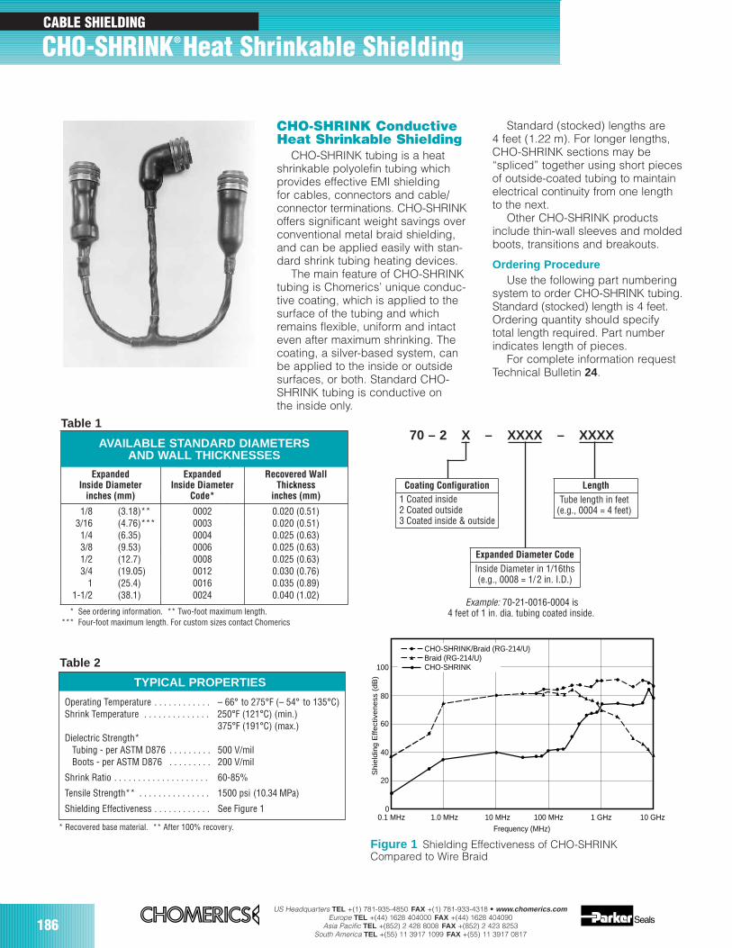
186US Headquarters TEL +(1) 781-935-4850 FAX +(1) 781-933-4318 • www.chomerics.com
Europe TEL +(44) 1628 404000 FAX +(44) 1628 404090Asia Pacific TEL +(852) 2 428 8008 FAX +(852) 2 423 8253
South America TEL +(55) 11 3917 1099 FAX +(55) 11 3917 0817
CHO-SHRINK Conductive Heat Shrinkable Shielding
CHO-SHRINK tubing is a heatshrinkable polyolefin tubing whichprovides effective EMI shieldingfor cables, connectors and cable/connector terminations. CHO-SHRINKoffers significant weight savings overconventional metal braid shielding,and can be applied easily with stan-dard shrink tubing heating devices.
The main feature of CHO-SHRINKtubing is Chomerics’ unique conduc-tive coating, which is applied to thesurface of the tubing and whichremains flexible, uniform and intacteven after maximum shrinking. Thecoating, a silver-based system, canbe applied to the inside or outsidesurfaces, or both. Standard CHO-SHRINK tubing is conductive onthe inside only.
ExpandedInside Diameter
inches (mm)ExpandedInside Diameter
Code*Recovered WallThickness
inches (mm) 1/8 (3.18)**3/16 (4.76)***
1/4 (6.35)3/8 (9.53)
ExpandedInside Diameter
inches (mm)
Recovered WallThickness
inches (mm)
00020003000400060008001200160024
0.020 (0.51)0.020 (0.51)0.025 (0.63)0.025 (0.63)0.025 (0.63)0.030 (0.76)0.035 (0.89)0.040 (1.02)
1/83/16 1/43/81/23/4
11-1/2
ExpandedInside Diameter
Code*
* See ordering information. ** Two-foot maximum length.*** Four-foot maximum length. For custom sizes contact Chomerics
TYPICAL PROPERTIES
Operating Temperature . . . . . . . . . . . . – 66° to 275°F (– 54° to 135°C)Shrink Temperature . . . . . . . . . . . . . . 250°F (121°C) (min.)
375°F (191°C) (max.)Dielectric Strength*
Tubing - per ASTM D876 . . . . . . . . . 500 V/milBoots - per ASTM D876 . . . . . . . . . 200 V/mil
Shrink Ratio . . . . . . . . . . . . . . . . . . . . 60-85%
Tensile Strength** . . . . . . . . . . . . . . . 1500 psi (10.34 MPa)
Shielding Effectiveness . . . . . . . . . . . . See Figure 1
Standard (stocked) lengths are 4 feet (1.22 m). For longer lengths,CHO-SHRINK sections may be“spliced” together using short piecesof outside-coated tubing to maintainelectrical continuity from one lengthto the next.
Other CHO-SHRINK productsinclude thin-wall sleeves and moldedboots, transitions and breakouts.
Ordering ProcedureUse the following part numbering
system to order CHO-SHRINK tubing.Standard (stocked) length is 4 feet.Ordering quantity should specifytotal length required. Part numberindicates length of pieces.
For complete information requestTechnical Bulletin 24.
* Recovered base material. ** After 100% recovery.
Inside Diameter in 1/16ths(e.g., 0008 = 1/2 in. I.D.)
Expanded Diameter Code
Length
70 – 2 X – XXXX – XXXX
Example: 70-21-0016-0004 is4 feet of 1 in. dia. tubing coated inside.
Figure 1 Shielding Effectiveness of CHO-SHRINKCompared to Wire Braid
Tube length in feet(e.g., 0004 = 4 feet)
Coating Configuration1 Coated inside2 Coated outside3 Coated inside & outside
CHO-SHRINK/Braid (RG-214/U)Braid (RG-214/U)CHO-SHRINK
0.1 MHz 1.0 MHz 10 MHz 100 MHz 1 GHz 10 GHz0
20
40
60
80
100
Frequency (MHz)
Shie
ldin
g E
ffect
iveness
(dB
)
(3.18)**(4.76)***(6.35)(9.53)(12.7)(19.05)(25.4)(38.1)
AVAILABLE STANDARD DIAMETERSAND WALL THICKNESSES
CHO-SHRINK® Heat Shrinkable ShieldingCABLE SHIELDING
Table 1
Table 2
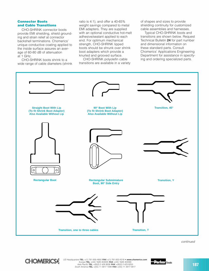
US Headquarters TEL +(1) 781-935-4850 FAX +(1) 781-933-4318 • www.chomerics.comEurope TEL +(44) 1628 404000 FAX +(44) 1628 404090
Asia Pacific TEL +(852) 2 428 8008 FAX +(852) 2 423 8253South America TEL +(55) 11 3917 1099 FAX +(55) 11 3917 0817
187
Connector Bootsand Cable Transitions
CHO-SHRINK connector bootsprovide EMI shielding, shield ground-ing and strain relief at connectorbackshell terminations. Chomerics’unique conductive coating applied tothe inside surface assures an aver-age of 60-80 dB of attenuationat 1 GHz.
CHO-SHRINK boots shrink to awide range of cable diameters (shrink
ratio is 4:1), and offer a 40-65%weight savings compared to metalEMI adapters. They are suppliedwith an optional conductive hot-meltadhesive/sealant applied to eachend. For optimum mechanicalstrength, CHO-SHRINK lippedboots should be shrunk over shrinkboot adapters which provide aknurled and grooved surface.
CHO-SHRINK polyolefin cabletransitions are available in a variety
Straight Boot With Lip(To fit Shrink Boot Adapter)Also Available Without Lip
90° Boot With Lip(To fit Shrink Boot Adapter)Also Available Without Lip
Transition, 45°
Rectangular Boot
Transition, one to three cables
Rectangular SubminiatureBoot, 90° Side Entry
Transition, Y
Transition, T
of shapes and sizes to provideshielding continuity for customizedcable assemblies and harnesses.
Typical CHO-SHRINK boots andtransitions are shown below. RequestTechnical Bulletin 24 for part numberand dimensional information onthese standard parts. ConsultChomerics’ Applications EngineeringDepartment for assistance in specify-ing and ordering specialized parts.
continued
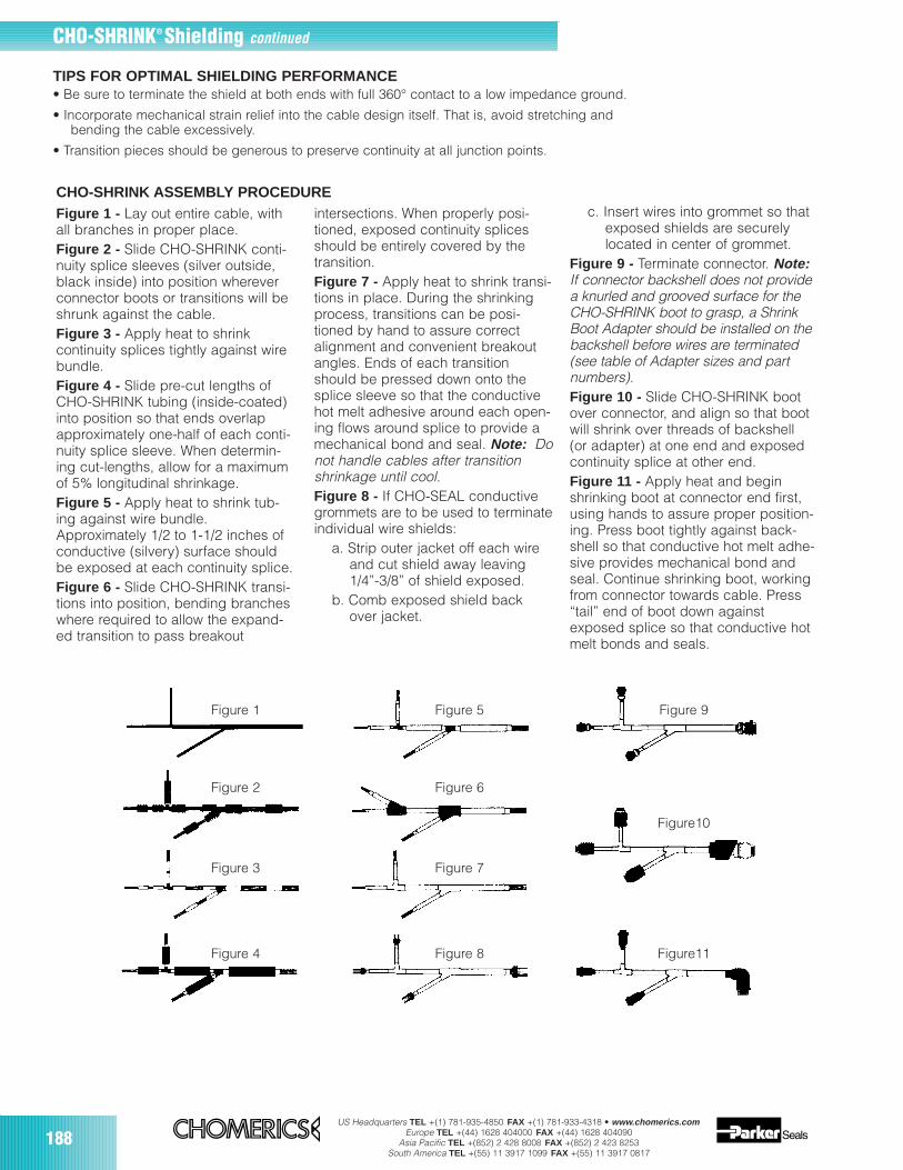
188US Headquarters TEL +(1) 781-935-4850 FAX +(1) 781-933-4318 • www.chomerics.com
Europe TEL +(44) 1628 404000 FAX +(44) 1628 404090Asia Pacific TEL +(852) 2 428 8008 FAX +(852) 2 423 8253
South America TEL +(55) 11 3917 1099 FAX +(55) 11 3917 0817
Figure 1 Figure 5 Figure 9
Figure 2 Figure 6
Figure10
Figure 3 Figure 7
Figure 4 Figure 8 Figure11
TIPS FOR OPTIMAL SHIELDING PERFORMANCE• Be sure to terminate the shield at both ends with full 360° contact to a low impedance ground.
• Incorporate mechanical strain relief into the cable design itself. That is, avoid stretching andbending the cable excessively.
• Transition pieces should be generous to preserve continuity at all junction points.
Figure 1 - Lay out entire cable, withall branches in proper place.Figure 2 - Slide CHO-SHRINK conti-nuity splice sleeves (silver outside,black inside) into position whereverconnector boots or transitions will beshrunk against the cable.Figure 3 - Apply heat to shrink continuity splices tightly against wirebundle.Figure 4 - Slide pre-cut lengths ofCHO-SHRINK tubing (inside-coated)into position so that ends overlapapproximately one-half of each conti-nuity splice sleeve. When determin-ing cut-lengths, allow for a maximumof 5% longitudinal shrinkage.Figure 5 - Apply heat to shrink tub-ing against wire bundle.Approximately 1/2 to 1-1/2 inches ofconductive (silvery) surface shouldbe exposed at each continuity splice.Figure 6 - Slide CHO-SHRINK transi-tions into position, bending brancheswhere required to allow the expand-ed transition to pass breakout
CHO-SHRINK® Shielding continued
intersections. When properly posi-tioned, exposed continuity splicesshould be entirely covered by thetransition.Figure 7 - Apply heat to shrink transi-tions in place. During the shrinkingprocess, transitions can be posi-tioned by hand to assure correctalignment and convenient breakoutangles. Ends of each transitionshould be pressed down onto thesplice sleeve so that the conductivehot melt adhesive around each open-ing flows around splice to provide amechanical bond and seal. Note: Donot handle cables after transitionshrinkage until cool.Figure 8 - If CHO-SEAL conductivegrommets are to be used to terminateindividual wire shields:
a. Strip outer jacket off each wireand cut shield away leaving1/4”-3/8” of shield exposed.
b. Comb exposed shield backover jacket.
CHO-SHRINK ASSEMBLY PROCEDUREc. Insert wires into grommet so that
exposed shields are securelylocated in center of grommet.
Figure 9 - Terminate connector. Note:If connector backshell does not providea knurled and grooved surface for theCHO-SHRINK boot to grasp, a ShrinkBoot Adapter should be installed on thebackshell before wires are terminated(see table of Adapter sizes and partnumbers).Figure 10 - Slide CHO-SHRINK bootover connector, and align so that bootwill shrink over threads of backshell(or adapter) at one end and exposedcontinuity splice at other end.Figure 11 - Apply heat and beginshrinking boot at connector end first,using hands to assure proper position-ing. Press boot tightly against back-shell so that conductive hot melt adhe-sive provides mechanical bond andseal. Continue shrinking boot, workingfrom connector towards cable. Press“tail” end of boot down againstexposed splice so that conductive hotmelt bonds and seals.
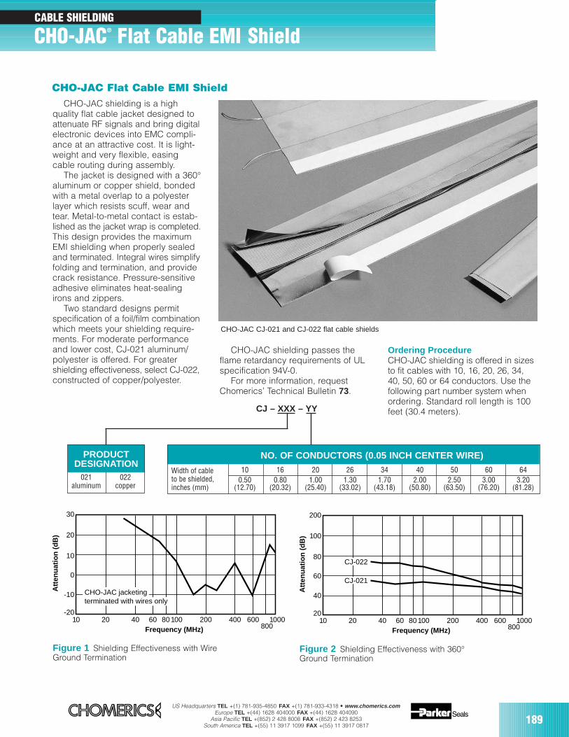
US Headquarters TEL +(1) 781-935-4850 FAX +(1) 781-933-4318 • www.chomerics.comEurope TEL +(44) 1628 404000 FAX +(44) 1628 404090
Asia Pacific TEL +(852) 2 428 8008 FAX +(852) 2 423 8253South America TEL +(55) 11 3917 1099 FAX +(55) 11 3917 0817
189
CABLE SHIELDING
CHO-JAC® Flat Cable EMI Shield
CHO-JAC shielding is a highquality flat cable jacket designed toattenuate RF signals and bring digitalelectronic devices into EMC compli-ance at an attractive cost. It is light-weight and very flexible, easingcable routing during assembly.
The jacket is designed with a 360°aluminum or copper shield, bondedwith a metal overlap to a polyesterlayer which resists scuff, wear andtear. Metal-to-metal contact is estab-lished as the jacket wrap is completed.This design provides the maximumEMI shielding when properly sealedand terminated. Integral wires simplifyfolding and termination, and providecrack resistance. Pressure-sensitiveadhesive eliminates heat-sealingirons and zippers.
Two standard designs permitspecification of a foil/film combinationwhich meets your shielding require-ments. For moderate performanceand lower cost, CJ-021 aluminum/polyester is offered. For greatershielding effectiveness, select CJ-022,constructed of copper/polyester.
CJ – XXX – YY
CHO-JAC CJ-021 and CJ-022 flat cable shields
10 20 40 60 80 100 200 400 600800
1000Frequency (MHz)
-20
-10
0
10
20
30
Att
enu
atio
n (
dB
)
CHO-JAC jacketingterminated with wires only
PRODUCTDESIGNATION
021 022aluminum copper
NO. OF CONDUCTORS (0.05 INCH CENTER WIRE)
Width of cable 10 16 20 26 34 40 50 60 64to be shielded, 0.50 0.80 1.00 1.30 1.70 2.00 2.50 3.00 3.20inches (mm) (12.70) (20.32) (25.40) (33.02) (43.18) (50.80) (63.50) (76.20) (81.28)
CHO-JAC Flat Cable EMI Shield
Figure 1 Shielding Effectiveness with Wire Ground Termination
CHO-JAC shielding passes theflame retardancy requirements of ULspecification 94V-0.
For more information, requestChomerics’ Technical Bulletin 73.
Ordering ProcedureCHO-JAC shielding is offered in sizesto fit cables with 10, 16, 20, 26, 34,40, 50, 60 or 64 conductors. Use thefollowing part number system whenordering. Standard roll length is 100feet (30.4 meters).
10 20 40 60 80 100 200 400 600800
1000Frequency (MHz)
20
40
60
80
100
200
Att
enu
atio
n (
dB
)
CJ-022
CJ-021
Figure 2 Shielding Effectiveness with 360°Ground Termination
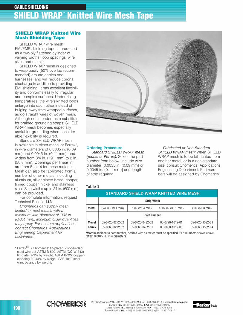
190US Headquarters TEL +(1) 781-935-4850 FAX +(1) 781-933-4318 • www.chomerics.com
Europe TEL +(44) 1628 404000 FAX +(44) 1628 404090Asia Pacific TEL +(852) 2 428 8008 FAX +(852) 2 423 8253
South America TEL +(55) 11 3917 1099 FAX +(55) 11 3917 0817
SHIELD WRAP wire meshEMI/EMP shielding tape is producedas a two-ply flattened cylinder ofvarying widths, loop spacings, wiresizes and metals.
SHIELD WRAP mesh is designedto wrap easily (50% overlap recom-mended) around cables andharnesses, and will reduce coronadischarge in addition to providingEMI shielding. It has excellent flexibil-ity and conforms easily to irregularand complex surfaces. Under risingtemperatures, the wire’s knitted loopsenlarge into each other instead ofbulging away from wrapped surfaces,as do straight wires of woven mesh.Although not intended as a substitutefor braided grounding straps, SHIELDWRAP mesh becomes especiallyuseful for grounding when consider-able flexibility is required.
Standard SHIELD WRAP mesh is available in either monel or Ferrex*,in wire diameters of 0.0035 in. (0.09mm) and 0.0045 in. (0.11 mm), andwidths from 3/4 in. (19.1 mm) to 2 in.(50.8 mm). Openings per linear in.are from 8 to 14 for these materials.Mesh can also be fabricated from anumber of other metals, includingaluminum, silver-plated brass, copper,tinned copper, nickel and stainlesssteel. Strip widths up to 24 in. (600 mm)can be provided.
For complete information, requestTechnical Bulletin 113.
Chomerics can supply mesh knitted in most metals with a minimum wire diameter of .002 in.(0.051 mm). Minimum order quantitiesmay apply. For custom applications,contact Chomerics’ ApplicationsEngineering Department for assistance.
Note: In addition to part number, desired wire diameter must be specified. Part numbers shown abovereflect 0.0045 in. wire diameters.
* Ferrex® is Chomerics’ tin-plated, copper-cladsteel wire per ASTM B-520. ASTM (QQ-W-343)tin-plate, 2-3% by weight; ASTM B-227 copper-cladding 30-40% by weight; SAE 1010 steelwire, balance by weight.
Ordering ProcedureStandard SHIELD WRAP mesh
(monel or Ferrex): Select the partnumber from below. Include wirediameter [0.0035 in. (0.09 mm) or0.0045 in. (0.11 mm)] and length of strip required.
STANDARD SHIELD WRAP KNITTED WIRE MESH
Strip Width
Metal 3/4 in. (19.1 mm) 1 in. (25.4 mm) 1-1/2 in. (38.1 mm) 2 in. (50.8 mm)
Part Number
Monel 05-0720-0272-02 05-0720-0432-02 05-0720-1012-01 05-0720-1532-01Ferrex 05-0860-0272-02 05-0860-0432-01 05-0860-1012-03 05-0860-1532-04
Fabricated or Non-StandardSHIELD WRAP mesh: When SHIELDWRAP mesh is to be fabricated fromanother metal, or in a non-standardsize, consult Chomerics’ ApplicationsEngineering Department. Part num-bers will be assigned by Chomerics.
SHIELD WRAP Knitted Wire Mesh Shielding Tape
Table 1
CABLE SHIELDING
SHIELD WRAP™ Knitted Wire Mesh Tape
SECTION CONTENTS PAGE
Theory of shielding and gasketing 192
Conductive elastomer gasket design 196
Gasket junction design 196
Corrosion 198
Selection of seal cross section 202
General tolerances 204
Gasket mounting choices 205
Fastener requirements 206
Designing a solid-O conductive elastomer gasket-in-a-groove 209
Mesh EMI gasketing selection guide 214
Glossary of terms 218
Part number cross reference index 220
EMI Shielding Theory& Gasket Design Guide
191
US Headquarters TEL +(1) 781-935-4850 FAX +(1) 781-933-4318 • www.chomerics.comEurope TEL +(44) 1628 404000 FAX +(44) 1628 404090
Asia Pacific TEL +(852) 2 428 8008 FAX +(852) 2 423 8253South America TEL +(55) 11 3917 1099 FAX +(55) 11 3917 0817
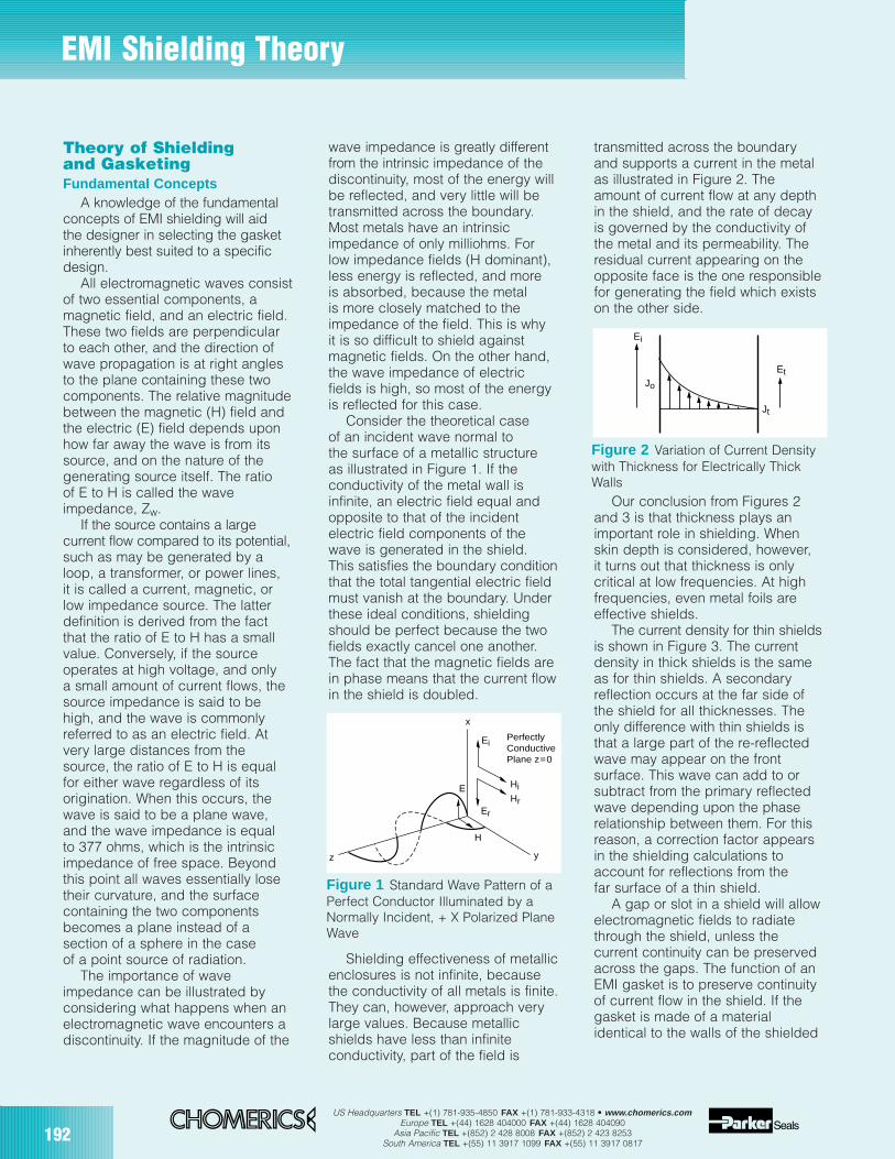
192US Headquarters TEL +(1) 781-935-4850 FAX +(1) 781-933-4318 • www.chomerics.com
Europe TEL +(44) 1628 404000 FAX +(44) 1628 404090Asia Pacific TEL +(852) 2 428 8008 FAX +(852) 2 423 8253
South America TEL +(55) 11 3917 1099 FAX +(55) 11 3917 0817
EMI Shielding Theory
Theory of Shieldingand GasketingFundamental Concepts
A knowledge of the fundamentalconcepts of EMI shielding will aidthe designer in selecting the gasketinherently best suited to a specificdesign.
All electromagnetic waves consistof two essential components, amagnetic field, and an electric field.These two fields are perpendicularto each other, and the direction ofwave propagation is at right anglesto the plane containing these twocomponents. The relative magnitudebetween the magnetic (H) field andthe electric (E) field depends uponhow far away the wave is from itssource, and on the nature of thegenerating source itself. The ratioof E to H is called the waveimpedance, Zw.
If the source contains a largecurrent flow compared to its potential,such as may be generated by aloop, a transformer, or power lines,it is called a current, magnetic, orlow impedance source. The latterdefinition is derived from the factthat the ratio of E to H has a smallvalue. Conversely, if the sourceoperates at high voltage, and onlya small amount of current flows, thesource impedance is said to behigh, and the wave is commonlyreferred to as an electric field. Atvery large distances from thesource, the ratio of E to H is equalfor either wave regardless of itsorigination. When this occurs, thewave is said to be a plane wave,and the wave impedance is equalto 377 ohms, which is the intrinsicimpedance of free space. Beyondthis point all waves essentially losetheir curvature, and the surfacecontaining the two componentsbecomes a plane instead of asection of a sphere in the caseof a point source of radiation.
The importance of waveimpedance can be illustrated byconsidering what happens when anelectromagnetic wave encounters adiscontinuity. If the magnitude of the
wave impedance is greatly differentfrom the intrinsic impedance of thediscontinuity, most of the energy willbe reflected, and very little will betransmitted across the boundary.Most metals have an intrinsicimpedance of only milliohms. Forlow impedance fields (H dominant),less energy is reflected, and moreis absorbed, because the metalis more closely matched to theimpedance of the field. This is whyit is so difficult to shield againstmagnetic fields. On the other hand,the wave impedance of electricfields is high, so most of the energyis reflected for this case.
Consider the theoretical caseof an incident wave normal tothe surface of a metallic structureas illustrated in Figure 1. If theconductivity of the metal wall isinfinite, an electric field equal andopposite to that of the incidentelectric field components of thewave is generated in the shield.This satisfies the boundary conditionthat the total tangential electric fieldmust vanish at the boundary. Underthese ideal conditions, shieldingshould be perfect because the twofields exactly cancel one another.The fact that the magnetic fields arein phase means that the current flowin the shield is doubled.
Shielding effectiveness of metallicenclosures is not infinite, becausethe conductivity of all metals is finite.They can, however, approach verylarge values. Because metallicshields have less than infiniteconductivity, part of the field is
transmitted across the boundaryand supports a current in the metalas illustrated in Figure 2. Theamount of current flow at any depthin the shield, and the rate of decayis governed by the conductivity ofthe metal and its permeability. Theresidual current appearing on theopposite face is the one responsiblefor generating the field which existson the other side.
Our conclusion from Figures 2and 3 is that thickness plays animportant role in shielding. Whenskin depth is considered, however,it turns out that thickness is onlycritical at low frequencies. At highfrequencies, even metal foils areeffective shields.
The current density for thin shieldsis shown in Figure 3. The currentdensity in thick shields is the sameas for thin shields. A secondaryreflection occurs at the far side ofthe shield for all thicknesses. Theonly difference with thin shields isthat a large part of the re-reflectedwave may appear on the frontsurface. This wave can add to orsubtract from the primary reflectedwave depending upon the phaserelationship between them. For thisreason, a correction factor appearsin the shielding calculations toaccount for reflections from thefar surface of a thin shield.
A gap or slot in a shield will allowelectromagnetic fields to radiatethrough the shield, unless thecurrent continuity can be preservedacross the gaps. The function of anEMI gasket is to preserve continuityof current flow in the shield. If thegasket is made of a materialidentical to the walls of the shielded
Figure 1 Standard Wave Pattern of aPerfect Conductor Illuminated by aNormally Incident, + X Polarized PlaneWave
z
Er
Hr
Hi
Ei
E
H
PerfectlyConductivePlane z=0
y
x
Figure 2 Variation of Current Densitywith Thickness for Electrically ThickWalls
Et
Jt
Jo
Ei
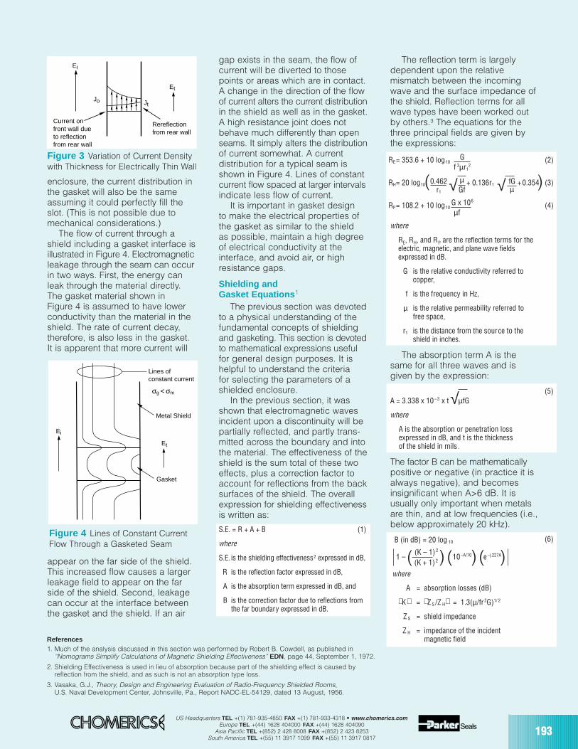
US Headquarters TEL +(1) 781-935-4850 FAX +(1) 781-933-4318 • www.chomerics.comEurope TEL +(44) 1628 404000 FAX +(44) 1628 404090
Asia Pacific TEL +(852) 2 428 8008 FAX +(852) 2 423 8253South America TEL +(55) 11 3917 1099 FAX +(55) 11 3917 0817
193
( ( () ) )(6)
enclosure, the current distribution inthe gasket will also be the sameassuming it could perfectly fill theslot. (This is not possible due tomechanical considerations.)
The flow of current through ashield including a gasket interface isillustrated in Figure 4. Electromagneticleakage through the seam can occurin two ways. First, the energy canleak through the material directly.The gasket material shown inFigure 4 is assumed to have lowerconductivity than the material in theshield. The rate of current decay,therefore, is also less in the gasket.It is apparent that more current will
appear on the far side of the shield.This increased flow causes a largerleakage field to appear on the farside of the shield. Second, leakagecan occur at the interface betweenthe gasket and the shield. If an air
gap exists in the seam, the flow ofcurrent will be diverted to thosepoints or areas which are in contact.A change in the direction of the flowof current alters the current distributionin the shield as well as in the gasket.A high resistance joint does notbehave much differently than openseams. It simply alters the distributionof current somewhat. A currentdistribution for a typical seam isshown in Figure 4. Lines of constantcurrent flow spaced at larger intervalsindicate less flow of current.
It is important in gasket designto make the electrical properties ofthe gasket as similar to the shieldas possible, maintain a high degreeof electrical conductivity at theinterface, and avoid air, or highresistance gaps.
Shielding andGasket Equations 1
The previous section was devotedto a physical understanding of thefundamental concepts of shieldingand gasketing. This section is devotedto mathematical expressions usefulfor general design purposes. It ishelpful to understand the criteriafor selecting the parameters of ashielded enclosure.
In the previous section, it wasshown that electromagnetic wavesincident upon a discontinuity will bepartially reflected, and partly trans-mitted across the boundary and intothe material. The effectiveness of theshield is the sum total of these twoeffects, plus a correction factor toaccount for reflections from the backsurfaces of the shield. The overallexpression for shielding effectivenessis written as:
S.E. = R + A + B (1)
where
S.E. is the shielding effectiveness2 expressed in dB,
R is the reflection factor expressed in dB,
A is the absorption term expressed in dB, and
B is the correction factor due to reflections fromthe far boundary expressed in dB.
The reflection term is largelydependent upon the relativemismatch between the incomingwave and the surface impedance ofthe shield. Reflection terms for allwave types have been worked outby others.3 The equations for thethree principal fields are given bythe expressions:
where
RE, RH, and RP are the reflection terms for theelectric, magnetic, and plane wave fieldsexpressed in dB.
G is the relative conductivity referred tocopper,
f is the frequency in Hz,
µ is the relative permeability referred tofree space,
r1 is the distance from the source to theshield in inches.
The absorption term A is thesame for all three waves and isgiven by the expression:
A = 3.338 x 10⁻³ x t µfG
where
A is the absorption or penetration lossexpressed in dB, and t is the thicknessof the shield in mils .
The factor B can be mathematicallypositive or negative (in practice it isalways negative), and becomesinsignificant when A>6 dB. It isusually only important when metalsare thin, and at low frequencies (i.e.,below approximately 20 kHz).
B (in dB) = 20 log 10
1 –(K – 1)2
10 –A/10 e–j.227A
(K + 1)2
where
A = absorption losses (dB)
K = ZS /Z H = 1.3(µ/fr 2G)1/ 2
ZS = shield impedance
Z H = impedance of the incidentmagnetic field
Figure 3 Variation of Current Densitywith Thickness for Electrically Thin Wall
Et
JtJo
Ei
Rereflectionfrom rear wall
Current onfront wall dueto reflectionfrom rear wall
Et
Ei
Gasket
Metal Shield
Lines ofconstant current
σg < σm
Figure 4 Lines of Constant CurrentFlow Through a Gasketed Seam
RE= 353.6 + 10 log10 G (2)
f 3µr12
RH= 20 log10 0.462 µ + 0.136r1 fG +0.354 (3)r1 Gf µ
RP= 108.2 + 10 log10 G x 106
(4)µf
√√( )
(5)
References1. Much of the analysis discussed in this section was performed by Robert B. Cowdell, as published in
“Nomograms Simplify Calculations of Magnetic Shielding Effectiveness” EDN, page 44, September 1, 1972.
2. Shielding Effectiveness is used in lieu of absorption because part of the shielding effect is caused byreflection from the shield, and as such is not an absorption type loss.
3. Vasaka, G.J., Theory, Design and Engineering Evaluation of Radio-Frequency Shielded Rooms,U.S. Naval Development Center, Johnsville, Pa., Report NADC-EL-54129, dated 13 August, 1956.
√
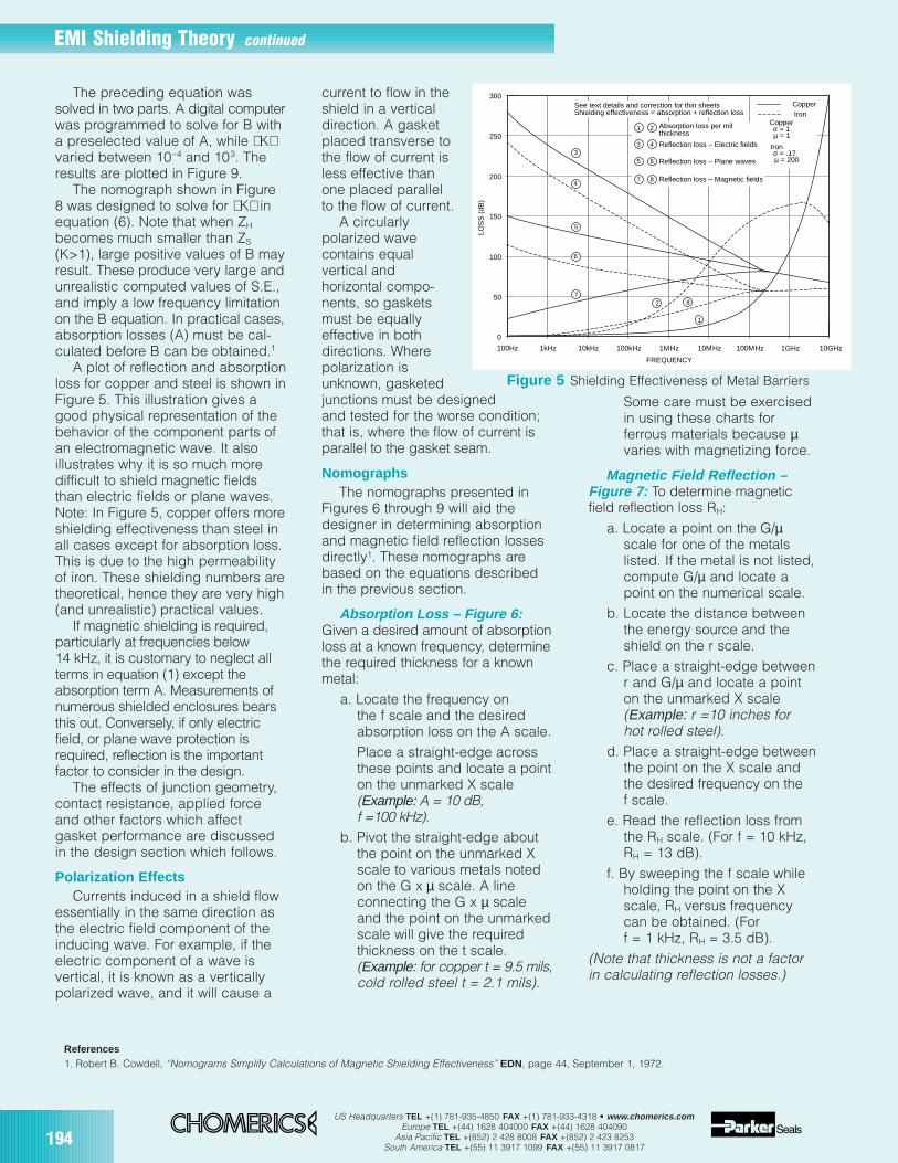
194US Headquarters TEL +(1) 781-935-4850 FAX +(1) 781-933-4318 • www.chomerics.com
Europe TEL +(44) 1628 404000 FAX +(44) 1628 404090Asia Pacific TEL +(852) 2 428 8008 FAX +(852) 2 423 8253
South America TEL +(55) 11 3917 1099 FAX +(55) 11 3917 0817
The preceding equation wassolved in two parts. A digital computerwas programmed to solve for B witha preselected value of A, while Kvaried between 10–4 and 103. Theresults are plotted in Figure 9.
The nomograph shown in Figure8 was designed to solve for K inequation (6). Note that when ZH
becomes much smaller than ZS
(K>1), large positive values of B mayresult. These produce very large andunrealistic computed values of S.E.,and imply a low frequency limitationon the B equation. In practical cases,absorption losses (A) must be cal-culated before B can be obtained.1
A plot of reflection and absorptionloss for copper and steel is shown inFigure 5. This illustration gives agood physical representation of thebehavior of the component parts ofan electromagnetic wave. It alsoillustrates why it is so much moredifficult to shield magnetic fieldsthan electric fields or plane waves.Note: In Figure 5, copper offers moreshielding effectiveness than steel inall cases except for absorption loss.This is due to the high permeabilityof iron. These shielding numbers aretheoretical, hence they are very high(and unrealistic) practical values.
If magnetic shielding is required,particularly at frequencies below14 kHz, it is customary to neglect allterms in equation (1) except theabsorption term A. Measurements ofnumerous shielded enclosures bearsthis out. Conversely, if only electricfield, or plane wave protection isrequired, reflection is the importantfactor to consider in the design.
The effects of junction geometry,contact resistance, applied forceand other factors which affectgasket performance are discussedin the design section which follows.
Polarization EffectsCurrents induced in a shield flow
essentially in the same direction asthe electric field component of theinducing wave. For example, if theelectric component of a wave isvertical, it is known as a verticallypolarized wave, and it will cause a
current to flow in theshield in a verticaldirection. A gasketplaced transverse tothe flow of current isless effective thanone placed parallelto the flow of current.
A circularlypolarized wavecontains equalvertical andhorizontal compo-nents, so gasketsmust be equallyeffective in bothdirections. Wherepolarization isunknown, gasketedjunctions must be designedand tested for the worse condition;that is, where the flow of current isparallel to the gasket seam.
NomographsThe nomographs presented in
Figures 6 through 9 will aid thedesigner in determining absorptionand magnetic field reflection lossesdirectly1. These nomographs arebased on the equations describedin the previous section.
Absorption Loss – Figure 6:Given a desired amount of absorptionloss at a known frequency, determinethe required thickness for a knownmetal:
a. Locate the frequency onthe f scale and the desiredabsorption loss on the A scale.Place a straight-edge acrossthese points and locate a pointon the unmarked X scale(Example: A = 10 dB,f =100 kHz).
b. Pivot the straight-edge aboutthe point on the unmarked Xscale to various metals notedon the G x µ scale. A lineconnecting the G x µ scaleand the point on the unmarkedscale will give the requiredthickness on the t scale.(Example: for copper t = 9.5 mils,cold rolled steel t = 2.1 mils).
Some care must be exercisedin using these charts forferrous materials because µvaries with magnetizing force.
Magnetic Field Reflection –Figure 7: To determine magneticfield reflection loss RH:
a. Locate a point on the G/µscale for one of the metalslisted. If the metal is not listed,compute G/µ and locate apoint on the numerical scale.
b. Locate the distance betweenthe energy source and theshield on the r scale.
c. Place a straight-edge betweenr and G/µ and locate a pointon the unmarked X scale(Example: r =10 inches forhot rolled steel).
d. Place a straight-edge betweenthe point on the X scale andthe desired frequency on thef scale.
e. Read the reflection loss fromthe RH scale. (For f = 10 kHz,RH = 13 dB).
f. By sweeping the f scale whileholding the point on the Xscale, RH versus frequencycan be obtained. (Forf = 1 kHz, RH = 3.5 dB).
(Note that thickness is not a factorin calculating reflection losses.)
EMI Shielding Theory continued
References1. Robert B. Cowdell, “Nomograms Simplify Calculations of Magnetic Shielding Effectiveness” EDN, page 44, September 1, 1972.
100Hz 1kHz 10kHz 100kHz 1MHz 10MHz 100MHz 1GHz 10GHz
0
50
100
150
200
250
300
5
4
3
6
72 8
1
IronCopper
FREQUENCY
LOS
S (
dB)
See text details and correction for thin sheetsShielding effectiveness = absorption + reflection loss
1 2Copper σ = 1 µ = 1
3 4
5 6
7 8
Absorption loss per milthickness
Reflection loss – Electric fields
Reflection loss – Plane waves
Reflection loss – Magnetic fields
Iron σ = .17 µ = 200
Figure 5 Shielding Effectiveness of Metal Barriers
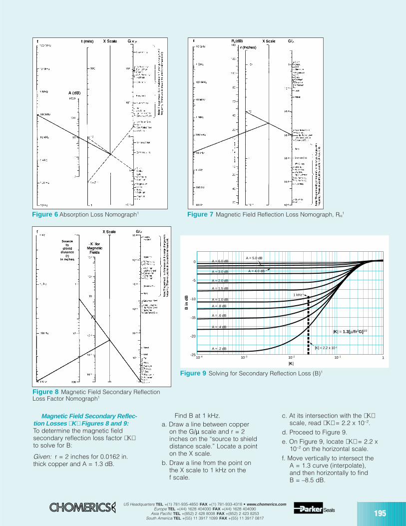
US Headquarters TEL +(1) 781-935-4850 FAX +(1) 781-933-4318 • www.chomerics.comEurope TEL +(44) 1628 404000 FAX +(44) 1628 404090
Asia Pacific TEL +(852) 2 428 8008 FAX +(852) 2 423 8253South America TEL +(55) 11 3917 1099 FAX +(55) 11 3917 0817
195
Magnetic Field Secondary Reflec-tion Losses K Figures 8 and 9:To determine the magnetic fieldsecondary reflection loss factor Kto solve for B:
Given: r = 2 inches for 0.0162 in.thick copper and A = 1.3 dB.
Find B at 1 kHz.a. Draw a line between copper
on the G/µ scale and r = 2inches on the “source to shielddistance scale.” Locate a pointon the X scale.
b. Draw a line from the point onthe X scale to 1 kHz on thef scale.
c. At its intersection with the Kscale, read K = 2.2 x 10⁻².
d. Proceed to Figure 9.e. On Figure 9, locate K = 2.2 x
10–2 on the horizontal scale. f. Move vertically to intersect the
A = 1.3 curve (interpolate),and then horizontally to findB = –8.5 dB.
Figure 7 Magnetic Field Reflection Loss Nomograph, RH1
Figure 8 Magnetic Field Secondary ReflectionLoss Factor Nomograph1
A = 6.0 dBA = 5.0 dB
A = 4.0 dB
1 kHz
A = 3.0 dB
A = 2.0 dB
A = 1.5 dB
A = 1.0 dB
A = .8 dB
A = .6 dB
A = .4 dB
A = .2 dB
10 -4 10 -3 10 -2 10 -1 1-25
-20
-15
-10
-5
0
B in
dB
|K|
|K| = 1.3[µ/fr2G]1/2
|K| = 2.2 x 10⁻²
Figure 6 Absorption Loss Nomograph1
Figure 9 Solving for Secondary Reflection Loss (B)1
196US Headquarters TEL +(1) 781-935-4850 FAX +(1) 781-933-4318 • www.chomerics.com
Europe TEL +(44) 1628 404000 FAX +(44) 1628 404090Asia Pacific TEL +(852) 2 428 8008 FAX +(852) 2 423 8253
South America TEL +(55) 11 3917 1099 FAX +(55) 11 3917 0817
Conductive Elastomer Gasket Design*
* Complete solid-O gasket design information starts on page 209.
Gasket Junction DesignThe ideal gasketing surface is
rigid and recessed to completelyhouse the gasket. Moreover, itshould be as conductive aspossible. Metal surfaces matingwith the gasket ideally should benon-corrosive. Where reaction withthe environment is inevitable,the reaction products should beelectrically conductive or easilypenetrable by mechanical abrasion.It is here that many gasket designsfail. The designer could not, or didnot treat the mating surface with thesame care as that given to theselection of the gasketing material.
By definition, a gasket is necessaryonly where an imperfect surfaceexists. If the junction were perfect,which includes either a solidlywelded closure, or one with matingsurfaces infinitely stiff, perfectly flat,or with infinite conductivity acrossthe junction, no gasket would benecessary. The more imperfect themating surfaces, the more critical isthe function of the gasket. Perfectsurfaces are expensive. The finalsolution is generally a compromisebetween economics and performance,but it should not be at the expenseof neglecting the design of theflange surfaces.
The important property thatmakes a conductive elastomergasket a good EMI/EMP seal is itsability to provide good electricalconductivity across the gasket-flange interface. Generally, the betterthe conformability and conductivity,the higher the shielding effectivenessof the gasket. In practice, it hasbeen found that surface conductivityof both the gasket and the matingsurfaces is the single most importantproperty that makes the gasketedseam effective; i.e., the resistancebetween the flange and gasketshould be as low as possible.
At this stage of the design everyeffort should be given to choosing aflange that will be as stiff as possibleconsistent with the construction usedand within the other designconstraints.
1. Flange MaterialsFlanges are generally made of the
same material as the basic enclosurefor reasons of economy, weldability,strength and resistance to corrosion.Wherever possible, the flangesshould be made of materials with thehighest possible conductivity. It isadvisable to add caution notes ondrawings not to paint the flangemating surfaces. If paint is to beapplied to outside surfaces, be surethat the contact surfaces are wellmasked before paint is applied, andthen cleaned after the masking tapeis removed. If the assembled unitsare subject to painting or repaintingin the field, add a cautionary note ina conspicuous location adjacent tothe seal that the seal areas are to bemasked before painting.
Ordinarily, the higher the conduc-tivity of a material, the more readily itoxidizes – except for noble metalssuch as gold and silver. Gold isimpervious to oxidation, and silver,although it oxidizes, forms oxidesthat are soft and relatively conductive.
Most oxides, however, are hard.Some of the oxide layers remain thinwhile others build up to substantialthickness in relatively short time.These oxides form insulating, orsemi-conducting films at theboundary between the gasket andthe flanges. This effect can beovercome to a degree by usingmaterials that do not oxidize readily,or by coating the surface with aconductive material that is lesssubject to oxidation. Nickel plating isgenerally recommended foraluminum parts, although tin has
become widely accepted. Zinc isprimarily used with steel. Consult theapplicable specifications beforeselecting a finish. A good guide tofinishing EMI shielded flanges foraerospace applications has beenpublished by SAE Committee AE-4(Electromagnetic Compatibility)under the designation ARP 1481. Adiscussion of corrosion controlfollows later in this guide.
2. Advantages of Grooved DesignsAll rubber materials are subject to
“Compression Set,” especially ifover compressed. Because flangesurfaces cannot be held uniformlyflat when the bolts are tightened(unless the flanges are infinitelystiff), gaskets tend to overcompressin the areas of the bolts. Propergroove design is required to avoidthis problem of over compression. Agroove also provides metal-to-metalcontact between the flange members,thereby reducing contact resistanceacross the junction.
A single groove will suffice for mostdesigns. Adding a second grooveparallel to the first adds approximately6 dB to the overall performance ofa single-groove design. Addingmore grooves beyond the seconddoes not increase the gasketingeffectiveness significantly.
3. Flange Design ConsiderationsMost designers fight a space
limitation, particularly in the vicinityof the gasketed seam. Complexfasteners are often required to makethe junctions more compact.
The ideal flange includes agroove for limiting the deflection of agasket. The screw or bolt fastenersare mounted outboard of the gasketto eliminate the need for providinggaskets under the fasteners. Amachined flange and its recom-mended groove dimensions areshown in Figure 10. The gasket may
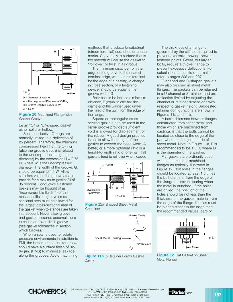
US Headquarters TEL +(1) 781-935-4850 FAX +(1) 781-933-4318 • www.chomerics.comEurope TEL +(44) 1628 404000 FAX +(44) 1628 404090
Asia Pacific TEL +(852) 2 428 8008 FAX +(852) 2 423 8253South America TEL +(55) 11 3917 1099 FAX +(55) 11 3917 0817
197
be an “O” or “D”-shaped gasket,either solid or hollow.
Solid conductive O-rings arenormally limited to a deflection of25 percent. Therefore, the minimumcompressed height of the O-ring(also the groove depth) is relatedto the uncompressed height (ordiameter) by the expression H = 0.75W, where W is the uncompresseddiameter. The width of the groove, G,should be equal to 1.1 W. Allowsufficient void in the groove area toprovide for a maximum gasket fill of95 percent. Conductive elastomergaskets may be thought of as“incompressible fluids.” For thisreason, sufficient groove crosssectional area must be allowed forthe largest cross-sectional area ofthe gasket when tolerances are takeninto account. Never allow grooveand gasket tolerance accumulationsto cause an “over-filled” groove(see gasket tolerances in sectionwhich follows).
When a seal is used to isolatepressure environments in addition toEMI, the bottom of the gasket grooveshould have a surface finish of 32-64 µin. (RMS) to minimize leakagealong the grooves. Avoid machining
methods that produce longitudinal(circumferential) scratches or chattermarks. Conversely, a surface that istoo smooth will cause the gasket to“roll over” or twist in its groove.
The minimum distance from theedge of the groove to the nearestterminal edge, whether this terminalbe the edge of a casting, a changein cross section, or a fasteningdevice, should be equal to thegroove width, G.
Bolts should be located a minimumdistance, E (equal to one-half thediameter of the washer used underthe head of the bolt) from the edge ofthe flange.
Square or rectangular crosssection gaskets can be used in thesame groove provided sufficientvoid is allowed for displacement ofthe rubber. A good design practiceis not to allow the height of thegasket to exceed the base width. Abetter, or a more optimum ratio is aheight-to-width ratio of one-half. Tallgaskets tend to roll over when loaded.
The thickness of a flange isgoverned by the stiffness required toprevent excessive bowing betweenfastener points. Fewer, but largerbolts, require a thicker flange toprevent excessive deflections. Forcalculations of elastic deformation,refer to pages 206 and 207.
O-shaped and D-shaped gasketsmay also be used in sheet metalflanges. The gaskets can be retainedin a U-channel or Z-retainer, and aredeflection-limited by adjusting thechannel or retainer dimensions withrespect to gasket height. Suggestedretainer configurations are shown inFigures 11a and 11b.
A basic difference between flangesconstructed from sheet metal andthose which are machined fromcastings is that the bolts cannot belocated as close to the edge of thepart when the flange is made ofsheet metal. Note, in Figure 11a, F isrecommended to be 1.5 D, where Dis the diameter of the washer.
Flat gaskets are ordinarily usedwith sheet metal or machinedflanges as typically illustrated inFigure 12. Bolt holes in the flangesshould be located at least 1.5 timesthe bolt diameter from the edge ofthe flange to prevent tearing whenthe metal is punched. If the holesare drilled, the position of theholes should be not less than thethickness of the gasket material fromthe edge of the flange. If holes mustbe placed closer to the edge thanthe recommended values, ears or
GG G
H
EE = D2
D = Diameter of WasherW = Uncompressed Diameter of O-RingH = Groove Depth = 0.75-0.90 WG = 1.1 W
Figure 10 Machined Flange withGasket Groove
D
G
WH
Cover
OverlappingSpot Welds
F = 1.5 D
Gasket Cavity
"Z" Retainer
Sheet Metal Housing
F
Figure 11a Shaped Sheet MetalContainer
Figure 11b Z-Retainer Forms GasketCavity
F
t
F = t
Figure 12 Flat Gasket on SheetMetal Flange
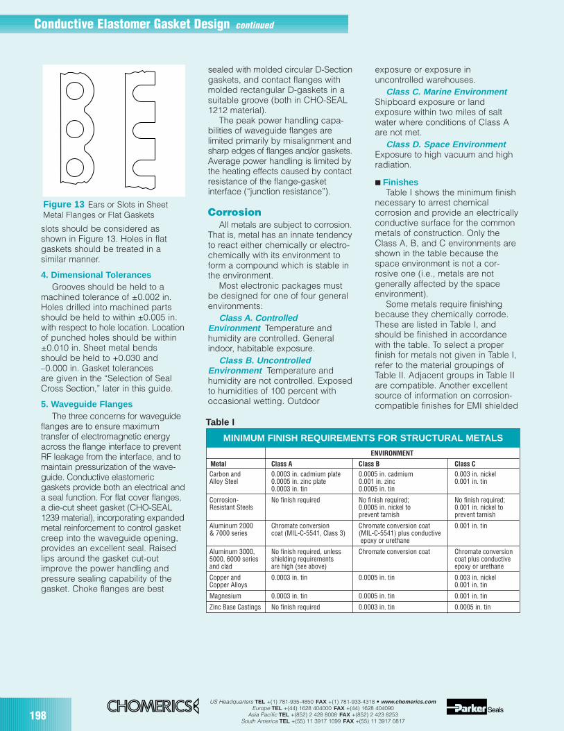
198US Headquarters TEL +(1) 781-935-4850 FAX +(1) 781-933-4318 • www.chomerics.com
Europe TEL +(44) 1628 404000 FAX +(44) 1628 404090Asia Pacific TEL +(852) 2 428 8008 FAX +(852) 2 423 8253
South America TEL +(55) 11 3917 1099 FAX +(55) 11 3917 0817
Conductive Elastomer Gasket Design continued
slots should be considered asshown in Figure 13. Holes in flatgaskets should be treated in asimilar manner.
4. Dimensional TolerancesGrooves should be held to a
machined tolerance of ±0.002 in.Holes drilled into machined partsshould be held to within ±0.005 in.with respect to hole location. Locationof punched holes should be within±0.010 in. Sheet metal bendsshould be held to +0.030 and–0.000 in. Gasket tolerancesare given in the “Selection of SealCross Section,” later in this guide.
5. Waveguide FlangesThe three concerns for waveguide
flanges are to ensure maximumtransfer of electromagnetic energyacross the flange interface to preventRF leakage from the interface, and tomaintain pressurization of the wave-guide. Conductive elastomericgaskets provide both an electrical anda seal function. For flat cover flanges,a die-cut sheet gasket (CHO-SEAL1239 material), incorporating expandedmetal reinforcement to control gasketcreep into the waveguide opening,provides an excellent seal. Raisedlips around the gasket cut-outimprove the power handling andpressure sealing capability of thegasket. Choke flanges are best
sealed with molded circular D-Sectiongaskets, and contact flanges withmolded rectangular D-gaskets in asuitable groove (both in CHO-SEAL1212 material).
The peak power handling capa-bilities of waveguide flanges arelimited primarily by misalignment andsharp edges of flanges and/or gaskets.Average power handling is limited bythe heating effects caused by contactresistance of the flange-gasketinterface (“junction resistance”).
CorrosionAll metals are subject to corrosion.
That is, metal has an innate tendencyto react either chemically or electro-chemically with its environment toform a compound which is stable inthe environment.
Most electronic packages mustbe designed for one of four generalenvironments:
Class A. ControlledEnvironment Temperature andhumidity are controlled. Generalindoor, habitable exposure.
Class B. UncontrolledEnvironment Temperature andhumidity are not controlled. Exposedto humidities of 100 percent withoccasional wetting. Outdoor
exposure or exposure inuncontrolled warehouses.
Class C. Marine EnvironmentShipboard exposure or landexposure within two miles of saltwater where conditions of Class Aare not met.
Class D. Space EnvironmentExposure to high vacuum and highradiation.
FinishesTable I shows the minimum finish
necessary to arrest chemicalcorrosion and provide an electricallyconductive surface for the commonmetals of construction. Only theClass A, B, and C environments areshown in the table because thespace environment is not a cor-rosive one (i.e., metals are notgenerally affected by the spaceenvironment).
Some metals require finishingbecause they chemically corrode.These are listed in Table I, andshould be finished in accordancewith the table. To select a properfinish for metals not given in Table I,refer to the material groupings ofTable II. Adjacent groups in Table IIare compatible. Another excellentsource of information on corrosion-compatible finishes for EMI shielded
ENVIRONMENT
Metal Class A Class B Class CCarbon and 0.0003 in. cadmium plate 0.0005 in. cadmium 0.003 in. nickelAlloy Steel 0.0005 in. zinc plate 0.001 in. zinc 0.001 in. tin
0.0003 in. tin 0.0005 in. tin
Corrosion- No finish required No finish required; No finish required;Resistant Steels 0.0005 in. nickel to 0.001 in. nickel to
prevent tarnish prevent tarnish
Aluminum 2000 Chromate conversion Chromate conversion coat 0.001 in. tin& 7000 series coat (MIL-C-5541, Class 3) (MIL-C-5541) plus conductive
epoxy or urethane
Aluminum 3000, No finish required, unless Chromate conversion coat Chromate conversion5000, 6000 series shielding requirements coat plus conductiveand clad are high (see above) epoxy or urethane
Copper and 0.0003 in. tin 0.0005 in. tin 0.003 in. nickelCopper Alloys 0.001 in. tin
Magnesium 0.0003 in. tin 0.0005 in. tin 0.001 in. tin
Zinc Base Castings No finish required 0.0003 in. tin 0.0005 in. tin
MINIMUM FINISH REQUIREMENTS FOR STRUCTURAL METALS
Table I
Figure 13 Ears or Slots in Sheet Metal Flanges or Flat Gaskets
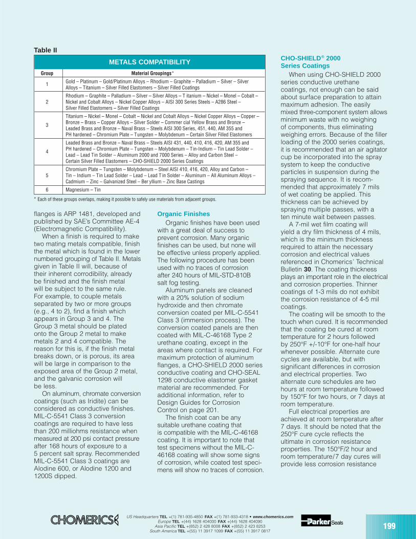
US Headquarters TEL +(1) 781-935-4850 FAX +(1) 781-933-4318 • www.chomerics.comEurope TEL +(44) 1628 404000 FAX +(44) 1628 404090
Asia Pacific TEL +(852) 2 428 8008 FAX +(852) 2 423 8253South America TEL +(55) 11 3917 1099 FAX +(55) 11 3917 0817
199
flanges is ARP 1481, developed andpublished by SAE’s Committee AE-4(Electromagnetic Compatibility).
When a finish is required to maketwo mating metals compatible, finishthe metal which is found in the lowernumbered grouping of Table II. Metalsgiven in Table II will, because oftheir inherent corrodibility, alreadybe finished and the finish metalwill be subject to the same rule.For example, to couple metalsseparated by two or more groups(e.g., 4 to 2), find a finish whichappears in Group 3 and 4. TheGroup 3 metal should be platedonto the Group 2 metal to makemetals 2 and 4 compatible. Thereason for this is, if the finish metalbreaks down, or is porous, its areawill be large in comparison to theexposed area of the Group 2 metal,and the galvanic corrosion willbe less.
On aluminum, chromate conversioncoatings (such as Iridite) can beconsidered as conductive finishes.MIL-C-5541 Class 3 conversioncoatings are required to have lessthan 200 milliohms resistance whenmeasured at 200 psi contact pressureafter 168 hours of exposure to a5 percent salt spray. RecommendedMIL-C-5541 Class 3 coatings areAlodine 600, or Alodine 1200 and1200S dipped.
Organic FinishesOrganic finishes have been used
with a great deal of success toprevent corrosion. Many organicfinishes can be used, but none willbe effective unless properly applied.The following procedure has beenused with no traces of corrosionafter 240 hours of MIL-STD-810Bsalt fog testing.
Aluminum panels are cleanedwith a 20% solution of sodiumhydroxide and then chromateconversion coated per MIL-C-5541Class 3 (immersion process). Theconversion coated panels are thencoated with MIL-C-46168 Type 2urethane coating, except in theareas where contact is required. Formaximum protection of aluminumflanges, a CHO-SHIELD 2000 seriesconductive coating and CHO-SEAL1298 conductive elastomer gasketmaterial are recommended. Foradditional information, refer toDesign Guides for CorrosionControl on page 201.
The finish coat can be anysuitable urethane coating thatis compatible with the MIL-C-46168coating. It is important to note thattest specimens without the MIL-C-46168 coating will show some signsof corrosion, while coated test speci-mens will show no traces of corrosion.
CHO-SHIELD® 2000Series Coatings
When using CHO-SHIELD 2000series conductive urethanecoatings, not enough can be saidabout surface preparation to attainmaximum adhesion. The easilymixed three-component system allowsminimum waste with no weighingof components, thus eliminatingweighing errors. Because of the fillerloading of the 2000 series coatings,it is recommended that an air agitatorcup be incorporated into the spraysystem to keep the conductiveparticles in suspension during thespraying sequence. It is recom-mended that approximately 7 milsof wet coating be applied. Thisthickness can be achieved byspraying multiple passes, with aten minute wait between passes.
A 7-mil wet film coating willyield a dry film thickness of 4 mils,which is the minimum thicknessrequired to attain the necessarycorrosion and electrical valuesreferenced in Chomerics’ TechnicalBulletin 30. The coating thicknessplays an important role in the electricaland corrosion properties. Thinnercoatings of 1-3 mils do not exhibitthe corrosion resistance of 4-5 milcoatings.
The coating will be smooth to thetouch when cured. It is recommendedthat the coating be cured at roomtemperature for 2 hours followedby 250°F +/-10°F for one-half hourwhenever possible. Alternate curecycles are available, but withsignificant differences in corrosionand electrical properties. Twoalternate cure schedules are twohours at room temperature followedby 150°F for two hours, or 7 days atroom temperature.
Full electrical properties areachieved at room temperature after7 days. It should be noted that the250°F cure cycle reflects theultimate in corrosion resistance properties. The 150°F/2 hour androom temperature/7 day cures willprovide less corrosion resistance
Group Material Groupings*
1 Gold – Platinum – Gold/Platinum Alloys – Rhodium – Graphite – Palladium – Silver – SilverAlloys – Titanium – Silver Filled Elastomers – Silver Filled Coatings
Rhodium – Graphite – Palladium – Silver – Silver Alloys – T itanium – Nickel – Monel – Cobalt –2 Nickel and Cobalt Alloys – Nickel Copper Alloys – AISI 300 Series Steels – A286 Steel –
Silver Filled Elastomers – Silver Filled Coatings
Titanium – Nickel – Monel – Cobalt – Nickel and Cobalt Alloys – Nickel Copper Alloys – Copper –
3 Bronze – Brass – Copper Alloys – Silver Solder – Commer cial Yellow Brass and Bronze – Leaded Brass and Bronze – Naval Brass – Steels AISI 300 Series, 451, 440, AM 355 and PH hardened – Chromium Plate – Tungsten – Molybdenum – Certain Silver Filled Elastomers
Leaded Brass and Bronze – Naval Brass – Steels AISI 431, 440, 410, 416, 420, AM 355 and
4 PH hardened – Chromium Plate – Tungsten – Molybdenum – Tin-Indium – Tin Lead Solder –Lead – Lead Tin Solder – Aluminum 2000 and 7000 Series – Alloy and Carbon Steel –Certain Silver Filled Elastomers – CHO-SHIELD 2000 Series Coatings
Chromium Plate – Tungsten – Molybdenum – Steel AISI 410, 416, 420, Alloy and Carbon –5 Tin – Indium – Tin Lead Solder – Lead – Lead T in Solder – Aluminum – All Aluminum Alloys –
Cadmium – Zinc – Galvanized Steel – Ber yllium – Zinc Base Castings
6 Magnesium – Tin
* Each of these groups overlaps, making it possible to safely use materials from adjacent groups.
METALS COMPATIBILITY
Table II
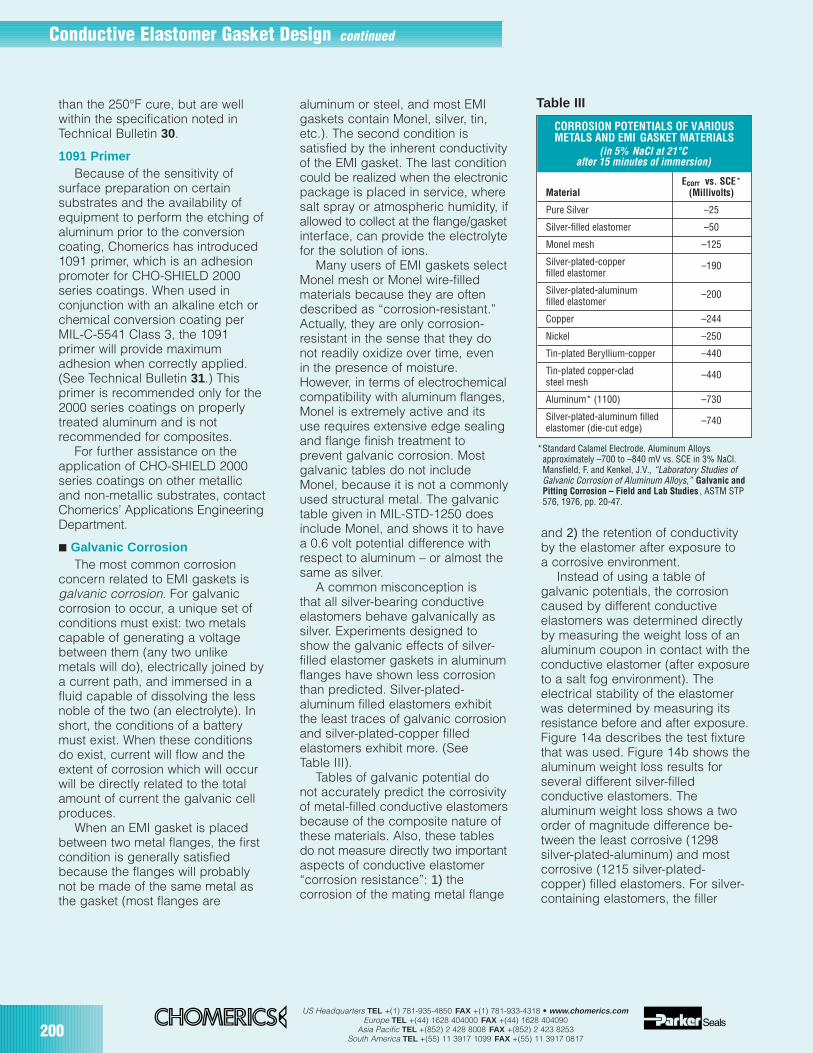
200US Headquarters TEL +(1) 781-935-4850 FAX +(1) 781-933-4318 • www.chomerics.com
Europe TEL +(44) 1628 404000 FAX +(44) 1628 404090Asia Pacific TEL +(852) 2 428 8008 FAX +(852) 2 423 8253
South America TEL +(55) 11 3917 1099 FAX +(55) 11 3917 0817
Conductive Elastomer Gasket Design continued
than the 250°F cure, but are wellwithin the specification noted inTechnical Bulletin 30.
1091 PrimerBecause of the sensitivity of
surface preparation on certainsubstrates and the availability ofequipment to perform the etching ofaluminum prior to the conversioncoating, Chomerics has introduced1091 primer, which is an adhesionpromoter for CHO-SHIELD 2000series coatings. When used inconjunction with an alkaline etch orchemical conversion coating perMIL-C-5541 Class 3, the 1091primer will provide maximumadhesion when correctly applied.(See Technical Bulletin 31.) Thisprimer is recommended only for the2000 series coatings on properlytreated aluminum and is notrecommended for composites.
For further assistance on theapplication of CHO-SHIELD 2000series coatings on other metallicand non-metallic substrates, contactChomerics’ Applications EngineeringDepartment.
Galvanic CorrosionThe most common corrosion
concern related to EMI gaskets isgalvanic corrosion. For galvaniccorrosion to occur, a unique set ofconditions must exist: two metalscapable of generating a voltagebetween them (any two unlikemetals will do), electrically joined bya current path, and immersed in afluid capable of dissolving the lessnoble of the two (an electrolyte). Inshort, the conditions of a batterymust exist. When these conditionsdo exist, current will flow and theextent of corrosion which will occurwill be directly related to the totalamount of current the galvanic cellproduces.
When an EMI gasket is placedbetween two metal flanges, the firstcondition is generally satisfiedbecause the flanges will probablynot be made of the same metal asthe gasket (most flanges are
aluminum or steel, and most EMIgaskets contain Monel, silver, tin,etc.). The second condition issatisfied by the inherent conductivityof the EMI gasket. The last conditioncould be realized when the electronicpackage is placed in service, wheresalt spray or atmospheric humidity, ifallowed to collect at the flange/gasketinterface, can provide the electrolytefor the solution of ions.
Many users of EMI gaskets selectMonel mesh or Monel wire-filledmaterials because they are oftendescribed as “corrosion-resistant.”Actually, they are only corrosion-resistant in the sense that they donot readily oxidize over time, evenin the presence of moisture.However, in terms of electrochemicalcompatibility with aluminum flanges,Monel is extremely active and itsuse requires extensive edge sealingand flange finish treatment toprevent galvanic corrosion. Mostgalvanic tables do not includeMonel, because it is not a commonlyused structural metal. The galvanictable given in MIL-STD-1250 doesinclude Monel, and shows it to havea 0.6 volt potential difference withrespect to aluminum – or almost thesame as silver.
A common misconception isthat all silver-bearing conductiveelastomers behave galvanically assilver. Experiments designed toshow the galvanic effects of silver-filled elastomer gaskets in aluminumflanges have shown less corrosionthan predicted. Silver-plated-aluminum filled elastomers exhibitthe least traces of galvanic corrosionand silver-plated-copper filledelastomers exhibit more. (SeeTable III).
Tables of galvanic potential donot accurately predict the corrosivityof metal-filled conductive elastomersbecause of the composite nature ofthese materials. Also, these tablesdo not measure directly two importantaspects of conductive elastomer“corrosion resistance”: 1) thecorrosion of the mating metal flange
and 2) the retention of conductivityby the elastomer after exposure toa corrosive environment.
Instead of using a table ofgalvanic potentials, the corrosioncaused by different conductiveelastomers was determined directlyby measuring the weight loss of analuminum coupon in contact with theconductive elastomer (after exposureto a salt fog environment). Theelectrical stability of the elastomerwas determined by measuring itsresistance before and after exposure.Figure 14a describes the test fixturethat was used. Figure 14b shows thealuminum weight loss results forseveral different silver-filledconductive elastomers. Thealuminum weight loss shows a twoorder of magnitude difference be-tween the least corrosive (1298silver-plated-aluminum) and mostcorrosive (1215 silver-plated-copper) filled elastomers. For silver-containing elastomers, the filler
*Standard Calamel Electrode. Aluminum Alloysapproximately –700 to –840 mV vs. SCE in 3% NaCl.Mansfield, F. and Kenkel, J.V., “Laboratory Studies ofGalvanic Corrosion of Aluminum Alloys,” Galvanic andPitting Corrosion – Field and Lab Studies , ASTM STP576, 1976, pp. 20-47.
Ecorr vs. SCE*Material (Millivolts)
Pure Silver –25
Silver-filled elastomer –50
Monel mesh –125
Silver-plated-copperfilled elastomer
–190
Silver-plated-aluminumfilled elastomer
–200
Copper –244
Nickel –250
Tin-plated Beryllium-copper –440
Tin-plated copper-cladsteel mesh
–440
Aluminum* (1100) –730
Silver-plated-aluminum filledelastomer (die-cut edge)
–740
CORROSION POTENTIALS OF VARIOUSMETALS AND EMI GASKET MATERIALS
(in 5% NaCI at 21°Cafter 15 minutes of immersion)
Table III
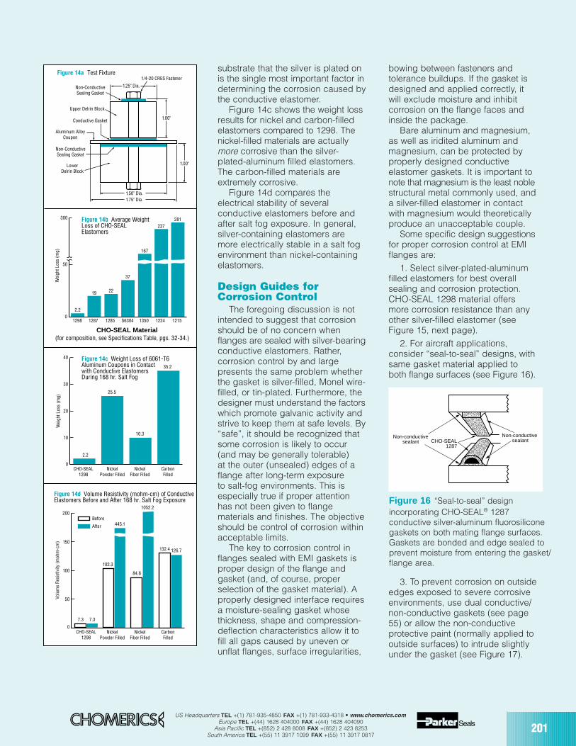
US Headquarters TEL +(1) 781-935-4850 FAX +(1) 781-933-4318 • www.chomerics.comEurope TEL +(44) 1628 404000 FAX +(44) 1628 404090
Asia Pacific TEL +(852) 2 428 8008 FAX +(852) 2 423 8253South America TEL +(55) 11 3917 1099 FAX +(55) 11 3917 0817
201
substrate that the silver is plated onis the single most important factor indetermining the corrosion caused bythe conductive elastomer.
Figure 14c shows the weight lossresults for nickel and carbon-filledelastomers compared to 1298. Thenickel-filled materials are actuallymore corrosive than the silver-plated-aluminum filled elastomers.The carbon-filled materials areextremely corrosive.
Figure 14d compares theelectrical stability of severalconductive elastomers before andafter salt fog exposure. In general,silver-containing elastomers aremore electrically stable in a salt fogenvironment than nickel-containingelastomers.
Design Guides forCorrosion Control
The foregoing discussion is notintended to suggest that corrosionshould be of no concern whenflanges are sealed with silver-bearingconductive elastomers. Rather,corrosion control by and largepresents the same problem whetherthe gasket is silver-filled, Monel wire-filled, or tin-plated. Furthermore, thedesigner must understand the factorswhich promote galvanic activity andstrive to keep them at safe levels. By“safe”, it should be recognized thatsome corrosion is likely to occur(and may be generally tolerable)at the outer (unsealed) edges of aflange after long-term exposureto salt-fog environments. This isespecially true if proper attentionhas not been given to flangematerials and finishes. The objectiveshould be control of corrosion withinacceptable limits.
The key to corrosion control inflanges sealed with EMI gaskets isproper design of the flange andgasket (and, of course, properselection of the gasket material). Aproperly designed interface requiresa moisture-sealing gasket whosethickness, shape and compression-deflection characteristics allow it tofill all gaps caused by uneven or unflat flanges, surface irregularities,
bowing between fasteners andtolerance buildups. If the gasket isdesigned and applied correctly, itwill exclude moisture and inhibitcorrosion on the flange faces andinside the package.
Bare aluminum and magnesium,as well as iridited aluminum andmagnesium, can be protected byproperly designed conductiveelastomer gaskets. It is important tonote that magnesium is the least noblestructural metal commonly used, anda silver-filled elastomer in contactwith magnesium would theoreticallyproduce an unacceptable couple.
Some specific design suggestionsfor proper corrosion control at EMIflanges are:
1. Select silver-plated-aluminumfilled elastomers for best overallsealing and corrosion protection.CHO-SEAL 1298 material offersmore corrosion resistance than anyother silver-filled elastomer (seeFigure 15, next page).
2. For aircraft applications,consider “seal-to-seal” designs, withsame gasket material applied toboth flange surfaces (see Figure 16).
3. To prevent corrosion on outsideedges exposed to severe corrosiveenvironments, use dual conductive/non-conductive gaskets (see page55) or allow the non-conductiveprotective paint (normally applied tooutside surfaces) to intrude slightlyunder the gasket (see Figure 17).
0
50
100
150
200
Volu
me
Res
istiv
ity (m
ohm
-cm
)
CHO-SEAL1298
1.50" Dia.
1.25" Dia.
1.75" Dia.
1/4-20 CRES Fastener
Non-ConductiveSealing Gasket
Non-ConductiveSealing Gasket
Upper Delrin Block
LowerDelrin Block
Conductive Gasket
Aluminum AlloyCoupon
1.00"
1.00"
1298 1287 1285 1350S6304 1224 1215
Wei
ght L
oss
(mg)
50
0
300
2.2
19 22
167
37
237281
0
10
20
30
40
Wei
ght L
oss
(mg)
CHO-SEAL1298
Nickel Powder Filled
NickelFiber Filled
CarbonFilled
NickelPowder Filled
NickelFiber Filled
CarbonFilled
2.2
25.5
10.3
35.2
Figure 14a Test Fixture
Figure 14b Average WeightLoss of CHO-SEALElastomers
Figure 14c Weight Loss of 6061-T6Aluminum Coupons in Contactwith Conductive ElastomersDuring 168 hr. Salt Fog
Figure 14d Volume Resistivity (mohm-cm) of Conductive Elastomers Before and After 168 hr. Salt Fog Exposure
7.3 7.3
102.3
445.1
84.8
132.4 126.7
1052.2
CHO-SEAL Material
Before
After
(for composition, see Specifications Table, pgs. 32-34.)
CHO-SEAL1287
Non-conductive
sealantNon-conductive
sealant
Figure 16 “Seal-to-seal” designincorporating CHO-SEAL® 1287conductive silver-aluminum fluorosiliconegaskets on both mating flange surfaces.Gaskets are bonded and edge sealed toprevent moisture from entering the gasket/flange area.
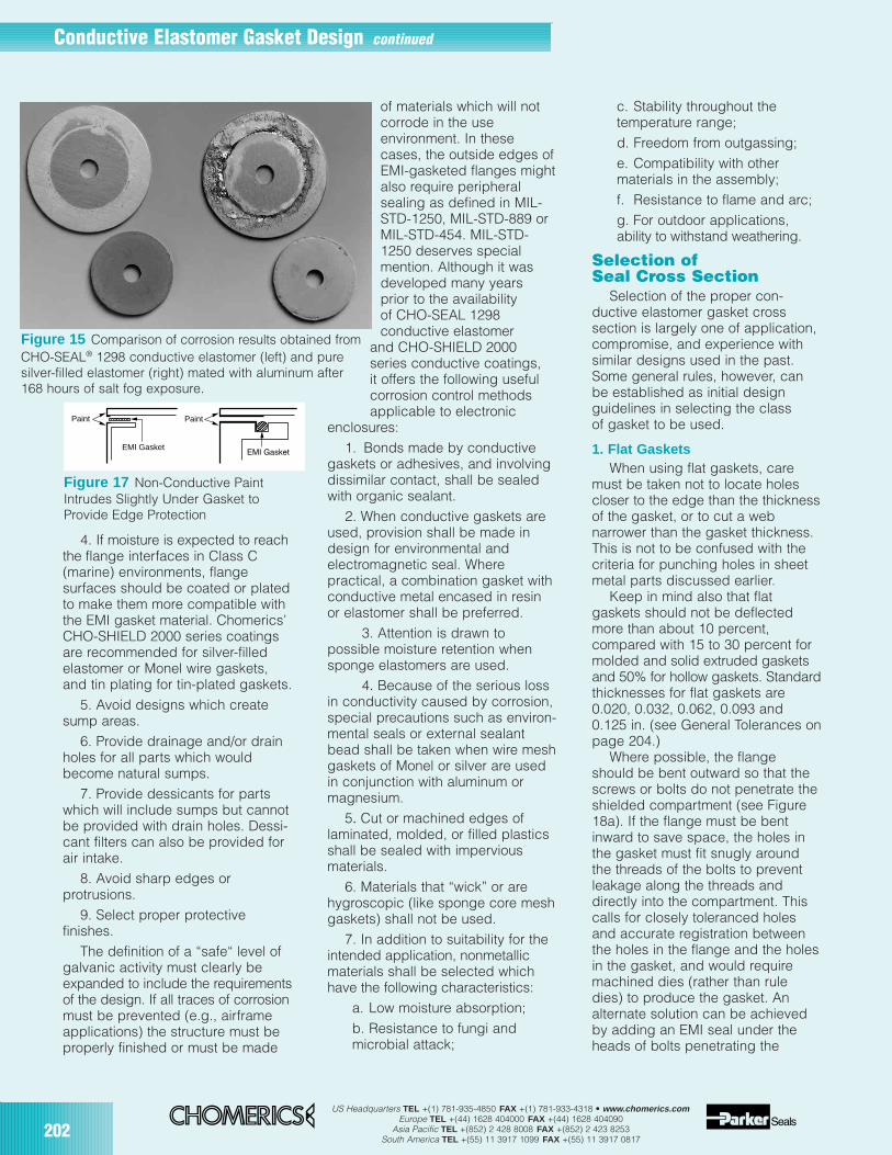
202US Headquarters TEL +(1) 781-935-4850 FAX +(1) 781-933-4318 • www.chomerics.com
Europe TEL +(44) 1628 404000 FAX +(44) 1628 404090Asia Pacific TEL +(852) 2 428 8008 FAX +(852) 2 423 8253
South America TEL +(55) 11 3917 1099 FAX +(55) 11 3917 0817
Conductive Elastomer Gasket Design continued
4. If moisture is expected to reachthe flange interfaces in Class C(marine) environments, flangesurfaces should be coated or platedto make them more compatible withthe EMI gasket material. Chomerics’CHO-SHIELD 2000 series coatingsare recommended for silver-filledelastomer or Monel wire gaskets,and tin plating for tin-plated gaskets.
5. Avoid designs which createsump areas.
6. Provide drainage and/or drainholes for all parts which wouldbecome natural sumps.
7. Provide dessicants for partswhich will include sumps but cannotbe provided with drain holes. Dessi-cant filters can also be provided forair intake.
8. Avoid sharp edges orprotrusions.
9. Select proper protectivefinishes.
The definition of a “safe“ level ofgalvanic activity must clearly beexpanded to include the requirementsof the design. If all traces of corrosionmust be prevented (e.g., airframeapplications) the structure must beproperly finished or must be made
of materials which will notcorrode in the useenvironment. In thesecases, the outside edges ofEMI-gasketed flanges mightalso require peripheralsealing as defined in MIL-STD-1250, MIL-STD-889 orMIL-STD-454. MIL-STD-1250 deserves specialmention. Although it wasdeveloped many yearsprior to the availabilityof CHO-SEAL 1298conductive elastomer
and CHO-SHIELD 2000series conductive coatings,it offers the following usefulcorrosion control methodsapplicable to electronic
enclosures:1. Bonds made by conductive
gaskets or adhesives, and involvingdissimilar contact, shall be sealedwith organic sealant.
2. When conductive gaskets areused, provision shall be made indesign for environmental andelectromagnetic seal. Wherepractical, a combination gasket withconductive metal encased in resinor elastomer shall be preferred.
3. Attention is drawn topossible moisture retention whensponge elastomers are used.
4. Because of the serious lossin conductivity caused by corrosion,special precautions such as environ-mental seals or external sealantbead shall be taken when wire meshgaskets of Monel or silver are usedin conjunction with aluminum ormagnesium.
5. Cut or machined edges oflaminated, molded, or filled plasticsshall be sealed with imperviousmaterials.
6. Materials that “wick” or arehygroscopic (like sponge core meshgaskets) shall not be used.
7. In addition to suitability for theintended application, nonmetallicmaterials shall be selected whichhave the following characteristics:
a. Low moisture absorption;b. Resistance to fungi andmicrobial attack;
c. Stability throughout thetemperature range;d. Freedom from outgassing;e. Compatibility with othermaterials in the assembly;f. Resistance to flame and arc;g. For outdoor applications,ability to withstand weathering.
Selection ofSeal Cross Section
Selection of the proper con-ductive elastomer gasket crosssection is largely one of application,compromise, and experience withsimilar designs used in the past.Some general rules, however, canbe established as initial designguidelines in selecting the classof gasket to be used.
1. Flat GasketsWhen using flat gaskets, care
must be taken not to locate holescloser to the edge than the thicknessof the gasket, or to cut a webnarrower than the gasket thickness.This is not to be confused with thecriteria for punching holes in sheetmetal parts discussed earlier.
Keep in mind also that flatgaskets should not be deflectedmore than about 10 percent,compared with 15 to 30 percent formolded and solid extruded gasketsand 50% for hollow gaskets. Standardthicknesses for flat gaskets are0.020, 0.032, 0.062, 0.093 and0.125 in. (see General Tolerances onpage 204.)
Where possible, the flangeshould be bent outward so that thescrews or bolts do not penetrate theshielded compartment (see Figure18a). If the flange must be bentinward to save space, the holes inthe gasket must fit snugly aroundthe threads of the bolts to preventleakage along the threads anddirectly into the compartment. Thiscalls for closely toleranced holesand accurate registration betweenthe holes in the flange and the holesin the gasket, and would requiremachined dies (rather than ruledies) to produce the gasket. Analternate solution can be achievedby adding an EMI seal under theheads of bolts penetrating the
EMI Gasket
Paint Paint
Figure 17 Non-Conductive PaintIntrudes Slightly Under Gasket toProvide Edge Protection
Figure 15 Comparison of corrosion results obtained fromCHO-SEAL® 1298 conductive elastomer (left) and puresilver-filled elastomer (right) mated with aluminum after168 hours of salt fog exposure.
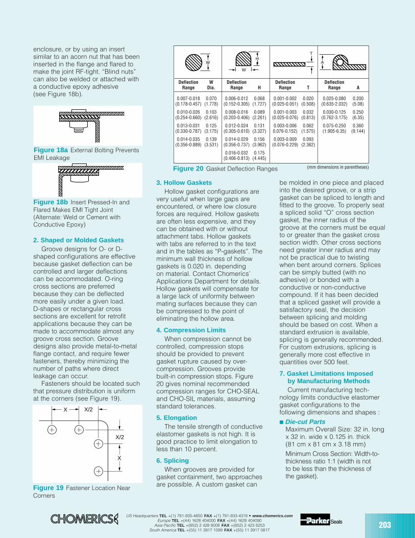
US Headquarters TEL +(1) 781-935-4850 FAX +(1) 781-933-4318 • www.chomerics.comEurope TEL +(44) 1628 404000 FAX +(44) 1628 404090
Asia Pacific TEL +(852) 2 428 8008 FAX +(852) 2 423 8253South America TEL +(55) 11 3917 1099 FAX +(55) 11 3917 0817
203
enclosure, or by using an insertsimilar to an acorn nut that has beeninserted in the flange and flared tomake the joint RF-tight. “Blind nuts”can also be welded or attached witha conductive epoxy adhesive(see Figure 18b).
2. Shaped or Molded GasketsGroove designs for O- or D-
shaped configurations are effectivebecause gasket deflection can becontrolled and larger deflectionscan be accommodated. O-ringcross sections are preferredbecause they can be deflectedmore easily under a given load.D-shapes or rectangular crosssections are excellent for retrofitapplications because they can bemade to accommodate almost anygroove cross section. Groovedesigns also provide metal-to-metalflange contact, and require fewerfasteners, thereby minimizing thenumber of paths where directleakage can occur.
Fasteners should be located suchthat pressure distribution is uniformat the corners (see Figure 19).
3. Hollow GasketsHollow gasket configurations are
very useful when large gaps areencountered, or where low closureforces are required. Hollow gasketsare often less expensive, and theycan be obtained with or withoutattachment tabs. Hollow gasketswith tabs are referred to in the textand in the tables as “P-gaskets”. Theminimum wall thickness of hollowgaskets is 0.020 in. dependingon material. Contact Chomerics’Applications Department for details.Hollow gaskets will compensate fora large lack of uniformity betweenmating surfaces because they canbe compressed to the point ofeliminating the hollow area.
4. Compression LimitsWhen compression cannot be
controlled, compression stopsshould be provided to preventgasket rupture caused by over-compression. Grooves providebuilt-in compression stops. Figure20 gives nominal recommendedcompression ranges for CHO-SEALand CHO-SIL materials, assumingstandard tolerances.
5. ElongationThe tensile strength of conductive
elastomer gaskets is not high. It isgood practice to limit elongation toless than 10 percent.
6. SplicingWhen grooves are provided for
gasket containment, two approachesare possible. A custom gasket can
be molded in one piece and placedinto the desired groove, or a stripgasket can be spliced to length andfitted to the groove. To properly seata spliced solid “O” cross sectiongasket, the inner radius of thegroove at the corners must be equalto or greater than the gasket crosssection width. Other cross sectionsneed greater inner radius and maynot be practical due to twistingwhen bent around corners. Splicescan be simply butted (with noadhesive) or bonded with aconductive or non-conductivecompound. If it has been decidedthat a spliced gasket will provide asatisfactory seal, the decisionbetween splicing and moldingshould be based on cost. When astandard extrusion is available,splicing is generally recommended.For custom extrusions, splicing isgenerally more cost effective inquantities over 500 feet.
7. Gasket Limitations Imposedby Manufacturing MethodsCurrent manufacturing tech-
nology limits conductive elastomergasket configurations to thefollowing dimensions and shapes : Die-cut Parts
Maximum Overall Size: 32 in. longx 32 in. wide x 0.125 in. thick(81 cm x 81 cm x 3.18 mm)Minimum Cross Section: Width-to-thickness ratio 1:1 (width is notto be less than the thickness ofthe gasket).
Figure 18a External Bolting PreventsEMI Leakage
Figure 18b Insert Pressed-In andFlared Makes EMI Tight Joint(Alternate: Weld or Cement withConductive Epoxy)
X/2
X/2
X
X
Figure 19 Fastener Location NearCorners
Figure 20 Gasket Deflection Ranges (mm dimensions in parentheses)
W
H
W
T
A
Deflection W Deflection Deflection DeflectionRange Dia. Range H Range T Range A
0.007-0.018 0.070 0.006-0.012 0.068 0.001-0.002 0.020 0.025-0.080 0.200(0.178-0.457) (1.778) (0.152-0.305) (1.727) (0.025-0.051) (0.508) (0.635-2.032) (5.08)
0.010-0.026 0.103 0.008-0.016 0.089 0.001-0.003 0.032 0.030-0.125 0.250(0.254-0.660) (2.616) (0.203-0.406) (2.261) (0.025-0.076) (0.813) (0.762-3.175) (6.35)
0.013-0.031 0.125 0.012-0.024 0.131 0.003-0.006 0.062 0.075-0.250 0.360(0.330-0.787) (3.175) (0.305-0.610) (3.327) 0.076-0.152) (1.575) (1.905-6.35) (9.144)
0.014-0.035 0.139 0.014-0.029 0.156 0.003-0.009 0.093(0.356-0.889) (3.531) (0.356-0.737) (3.962) (0.076-0.229) (2.362)
0.016-0.032 0.175(0.406-0.813) (4.445)
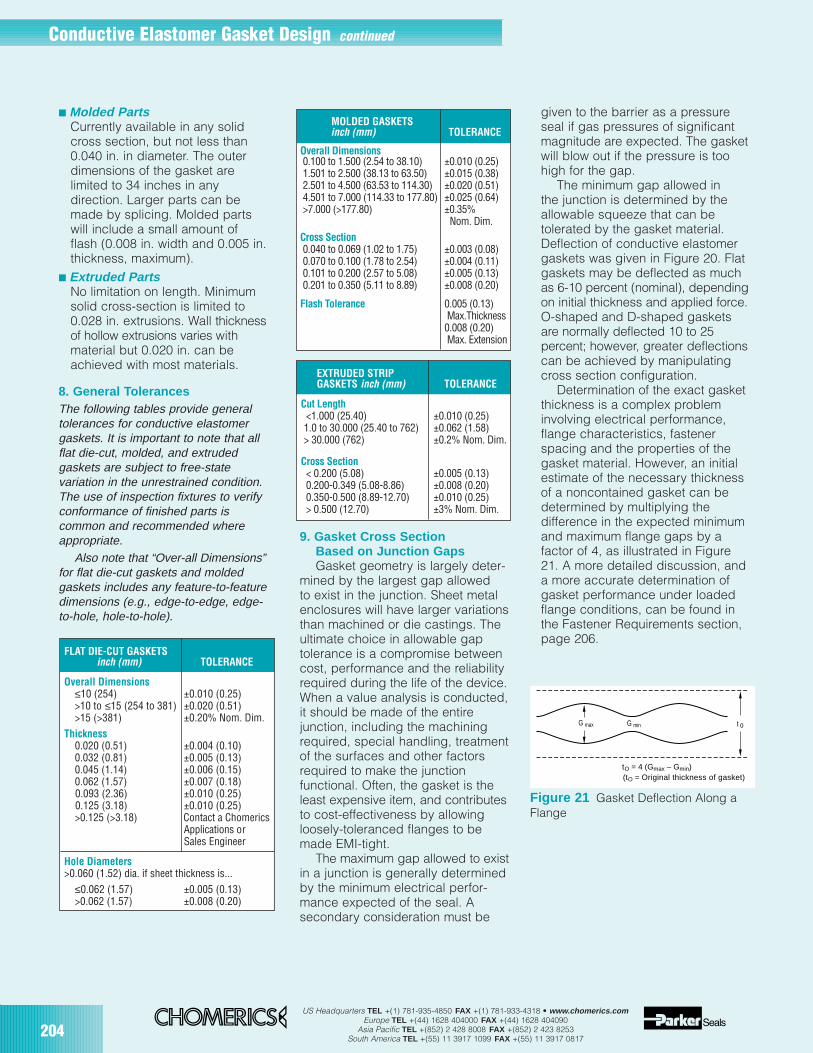
US Headquarters TEL +(1) 781-935-4850 FAX +(1) 781-933-4318 • www.chomerics.comEurope TEL +(44) 1628 404000 FAX +(44) 1628 404090
Asia Pacific TEL +(852) 2 428 8008 FAX +(852) 2 423 8253South America TEL +(55) 11 3917 1099 FAX +(55) 11 3917 0817
Molded PartsCurrently available in any solidcross section, but not less than0.040 in. in diameter. The outerdimensions of the gasket arelimited to 34 inches in anydirection. Larger parts can bemade by splicing. Molded partswill include a small amount offlash (0.008 in. width and 0.005 in.thickness, maximum).
Extruded PartsNo limitation on length. Minimumsolid cross-section is limited to0.028 in. extrusions. Wall thicknessof hollow extrusions varies withmaterial but 0.020 in. can beachieved with most materials.
8. General TolerancesThe following tables provide generaltolerances for conductive elastomergaskets. It is important to note that allflat die-cut, molded, and extrudedgaskets are subject to free-statevariation in the unrestrained condition.The use of inspection fixtures to verifyconformance of finished parts iscommon and recommended whereappropriate.
Also note that “Over-all Dimensions”for flat die-cut gaskets and moldedgaskets includes any feature-to-featuredimensions (e.g., edge-to-edge, edge-to-hole, hole-to-hole).
9. Gasket Cross SectionBased on Junction GapsGasket geometry is largely deter-
mined by the largest gap allowedto exist in the junction. Sheet metalenclosures will have larger variationsthan machined or die castings. Theultimate choice in allowable gaptolerance is a compromise betweencost, performance and the reliabilityrequired during the life of the device.When a value analysis is conducted,it should be made of the entirejunction, including the machiningrequired, special handling, treatmentof the surfaces and other factorsrequired to make the junctionfunctional. Often, the gasket is theleast expensive item, and contributesto cost-effectiveness by allowingloosely-toleranced flanges to bemade EMI-tight.
The maximum gap allowed to existin a junction is generally determinedby the minimum electrical perfor-mance expected of the seal. Asecondary consideration must be
given to the barrier as a pressureseal if gas pressures of significantmagnitude are expected. The gasketwill blow out if the pressure is toohigh for the gap.
The minimum gap allowed inthe junction is determined by theallowable squeeze that can betolerated by the gasket material.Deflection of conductive elastomergaskets was given in Figure 20. Flatgaskets may be deflected as muchas 6-10 percent (nominal), dependingon initial thickness and applied force.O-shaped and D-shaped gasketsare normally deflected 10 to 25percent; however, greater deflectionscan be achieved by manipulatingcross section configuration.
Determination of the exact gasketthickness is a complex probleminvolving electrical performance,flange characteristics, fastenerspacing and the properties of thegasket material. However, an initialestimate of the necessary thicknessof a noncontained gasket can bedetermined by multiplying thedifference in the expected minimumand maximum flange gaps by afactor of 4, as illustrated in Figure21. A more detailed discussion, anda more accurate determination ofgasket performance under loadedflange conditions, can be found inthe Fastener Requirements section,page 206.
204
Conductive Elastomer Gasket Design continued
Figure 21 Gasket Deflection Along aFlange
G max G min t o
tO = 4 (Gmax – Gmin)(tO = Original thickness of gasket)
EXTRUDED STRIPGASKETS inch (mm) TOLERANCE
Cut Length<1.000 (25.40) ±0.010 (0.25)1.0 to 30.000 (25.40 to 762) ±0.062 (1.58)> 30.000 (762) ±0.2% Nom. Dim.
Cross Section< 0.200 (5.08) ±0.005 (0.13)0.200-0.349 (5.08-8.86) ±0.008 (0.20)0.350-0.500 (8.89-12.70) ±0.010 (0.25)> 0.500 (12.70) ±3% Nom. Dim.
FLAT DIE-CUT GASKETSinch (mm) TOLERANCE
Overall Dimensions≤10 (254) ±0.010 (0.25)>10 to ≤15 (254 to 381) ±0.020 (0.51)>15 (>381) ±0.20% Nom. Dim.
Thickness0.020 (0.51) ±0.004 (0.10)0.032 (0.81) ±0.005 (0.13)0.045 (1.14) ±0.006 (0.15)0.062 (1.57) ±0.007 (0.18)0.093 (2.36) ±0.010 (0.25)0.125 (3.18) ±0.010 (0.25)>0.125 (>3.18) Contact a Chomerics
Applications or Sales Engineer
Hole Diameters>0.060 (1.52) dia. if sheet thickness is...
≤0.062 (1.57) ±0.005 (0.13)>0.062 (1.57) ±0.008 (0.20)
MOLDED GASKETSinch (mm) TOLERANCE
Overall Dimensions0.100 to 1.500 (2.54 to 38.10) ±0.010 (0.25)1.501 to 2.500 (38.13 to 63.50) ±0.015 (0.38)2.501 to 4.500 (63.53 to 114.30) ±0.020 (0.51)4.501 to 7.000 (114.33 to 177.80) ±0.025 (0.64)>7.000 (>177.80) ±0.35%
Nom. Dim.Cross Section0.040 to 0.069 (1.02 to 1.75) ±0.003 (0.08)0.070 to 0.100 (1.78 to 2.54) ±0.004 (0.11)0.101 to 0.200 (2.57 to 5.08) ±0.005 (0.13)0.201 to 0.350 (5.11 to 8.89) ±0.008 (0.20)
Flash Tolerance 0.005 (0.13) Max.Thickness0.008 (0.20) Max. Extension
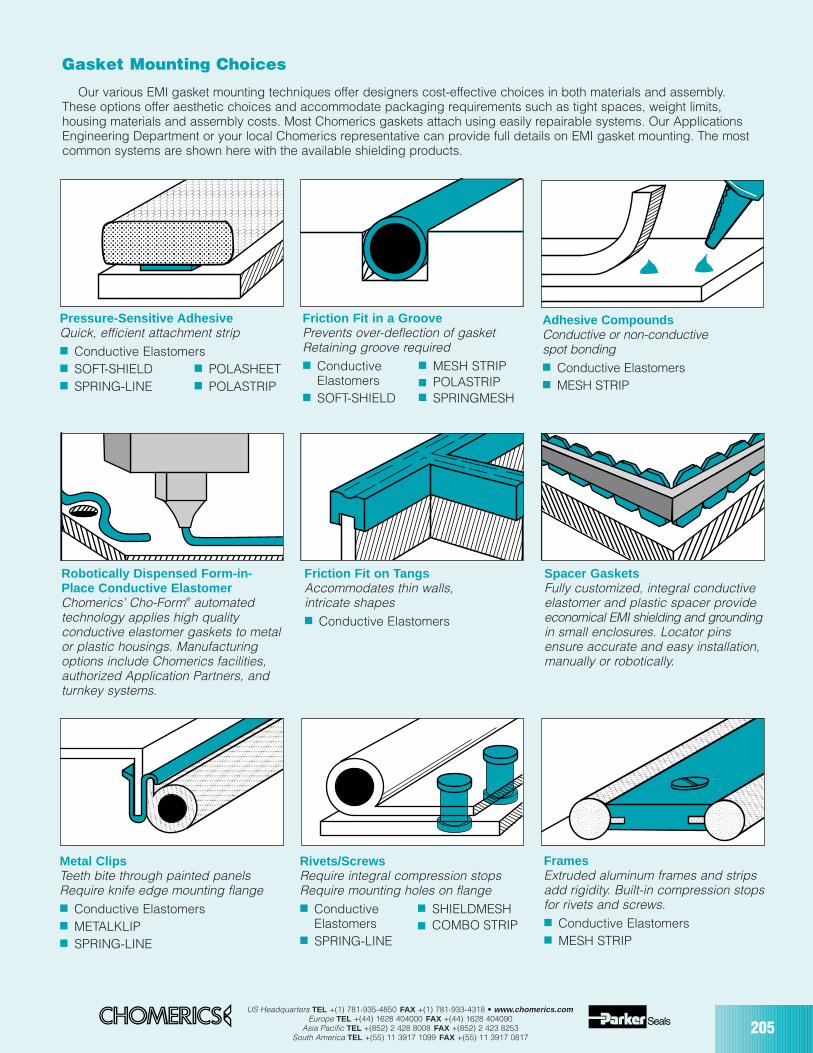
US Headquarters TEL +(1) 781-935-4850 FAX +(1) 781-933-4318 • www.chomerics.comEurope TEL +(44) 1628 404000 FAX +(44) 1628 404090
Asia Pacific TEL +(852) 2 428 8008 FAX +(852) 2 423 8253South America TEL +(55) 11 3917 1099 FAX +(55) 11 3917 0817
205
Our various EMI gasket mounting techniques offer designers cost-effective choices in both materials and assembly.These options offer aesthetic choices and accommodate packaging requirements such as tight spaces, weight limits,housing materials and assembly costs. Most Chomerics gaskets attach using easily repairable systems. Our ApplicationsEngineering Department or your local Chomerics representative can provide full details on EMI gasket mounting. The mostcommon systems are shown here with the available shielding products.
Pressure-Sensitive AdhesiveQuick, efficient attachment strip Conductive Elastomers SOFT-SHIELD POLASHEET SPRING-LINE POLASTRIP
Adhesive CompoundsConductive or non-conductivespot bonding Conductive Elastomers MESH STRIP
FramesExtruded aluminum frames and stripsadd rigidity. Built-in compression stopsfor rivets and screws. Conductive Elastomers MESH STRIP
Friction Fit in a GroovePrevents over-deflection of gasketRetaining groove required Conductive MESH STRIP
Elastomers POLASTRIP SOFT-SHIELD SPRINGMESH
Metal ClipsTeeth bite through painted panelsRequire knife edge mounting flange Conductive Elastomers METALKLIP SPRING-LINE
Rivets/ScrewsRequire integral compression stopsRequire mounting holes on flange Conductive SHIELDMESH
Elastomers SPRING-LINE
COMBO STRIP
Spacer GasketsFully customized, integral conductiveelastomer and plastic spacer provideeconomical EMI shielding and groundingin small enclosures. Locator pinsensure accurate and easy installation,manually or robotically.
Robotically Dispensed Form-in-Place Conductive ElastomerChomerics’ Cho-Form® automatedtechnology applies high qualityconductive elastomer gaskets to metalor plastic housings. Manufacturingoptions include Chomerics facilities,authorized Application Partners, andturnkey systems.
Friction Fit on TangsAccommodates thin walls,intricate shapes Conductive Elastomers
Gasket Mounting Choices
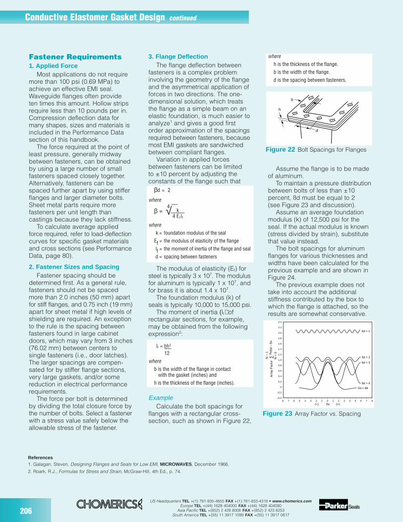
206US Headquarters TEL +(1) 781-935-4850 FAX +(1) 781-933-4318 • www.chomerics.com
Europe TEL +(44) 1628 404000 FAX +(44) 1628 404090Asia Pacific TEL +(852) 2 428 8008 FAX +(852) 2 423 8253
South America TEL +(55) 11 3917 1099 FAX +(55) 11 3917 0817
Fastener Requirements1. Applied Force
Most applications do not requiremore than 100 psi (0.69 MPa) toachieve an effective EMI seal.Waveguide flanges often provideten times this amount. Hollow stripsrequire less than 10 pounds per in.Compression deflection data formany shapes, sizes and materials isincluded in the Performance Datasection of this handbook.
The force required at the point ofleast pressure, generally midwaybetween fasteners, can be obtainedby using a large number of smallfasteners spaced closely together.Alternatively, fasteners can bespaced further apart by using stifferflanges and larger diameter bolts.Sheet metal parts require morefasteners per unit length thancastings because they lack stiffness.
To calculate average appliedforce required, refer to load-deflectioncurves for specific gasket materialsand cross sections (see PerformanceData, page 80).
2. Fastener Sizes and SpacingFastener spacing should be
determined first. As a general rule,fasteners should not be spacedmore than 2.0 inches (50 mm) apartfor stiff flanges, and 0.75 inch (19 mm)apart for sheet metal if high levels ofshielding are required. An exceptionto the rule is the spacing betweenfasteners found in large cabinetdoors, which may vary from 3 inches(76.02 mm) between centers tosingle fasteners (i.e., door latches).The larger spacings are compen-sated for by stiffer flange sections,very large gaskets, and/or somereduction in electrical performancerequirements.
The force per bolt is determinedby dividing the total closure force bythe number of bolts. Select a fastenerwith a stress value safely below theallowable stress of the fastener.
3. Flange DeflectionThe flange deflection between
fasteners is a complex probleminvolving the geometry of the flangeand the asymmetrical application offorces in two directions. The one-dimensional solution, which treatsthe flange as a simple beam on anelastic foundation, is much easier toanalyze1 and gives a good firstorder approximation of the spacingsrequired between fasteners, becausemost EMI gaskets are sandwichedbetween compliant flanges.
Variation in applied forcesbetween fasteners can be limitedto ±10 percent by adjusting theconstants of the flange such that
βd = 2,
where
β =
wherek = foundation modulus of the seal
Ef = the modulus of elasticity of the flange
lf = the moment of inertia of the flange and seal
d = spacing between fasteners
The modulus of elasticity (Ef) forsteel is typically 3 x 10⁷. The modulusfor aluminum is typically 1 x 10⁷, andfor brass it is about 1.4 x 10⁷.
The foundation modulus (k) ofseals is typically 10,000 to 15,000 psi.
The moment of inertia (lf) ofrectangular sections, for example,may be obtained from the followingexpression2:
lf = bh3
12
whereb is the width of the flange in contact
with the gasket (inches) andh is the thickness of the flange (inches).
ExampleCalculate the bolt spacings for
flanges with a rectangular cross-section, such as shown in Figure 22,
whereh is the thickness of the flange.b is the width of the flange.d is the spacing between fasteners.
Assume the flange is to be madeof aluminum.
To maintain a pressure distributionbetween bolts of less than ±10percent, ßd must be equal to 2(see Figure 23 and discussion).
Assume an average foundationmodulus (k) of 12,500 psi for theseal. If the actual modulus is known(stress divided by strain), substitutethat value instead.
The bolt spacings for aluminumflanges for various thicknesses andwidths have been calculated for theprevious example and are shown inFigure 24.
The previous example does nottake into account the additionalstiffness contributed by the box towhich the flange is attached, so theresults are somewhat conservative.
√4 k4 EfIf
h
b
d
Figure 22 Bolt Spacings for Flanges
References1. Galagan, Steven, Designing Flanges and Seals for Low EMI, MICROWAVES, December 1966.
2. Roark, R.J., Formulas for Stress and Strain, McGraw-Hill, 4th Ed., p. 74.
–0.4
–0.2
0
0.2
0.4
0.6
0.8
1.0
1.2
1.4
1.6
1.8
2.0
2.2
2.4
8 7 6 5 4 3 2 1 0 1 2 3 4 5 6 7 8
ßd = 1
ßd = 4
ßd = ∞
ßd = 2
ßd = 3
ßx (+)(–)
Arr
ay F
acto
r
N –
1
N =
0∑
Anß
d –
ßx
Figure 23 Array Factor vs. Spacing
Conductive Elastomer Gasket Design continued
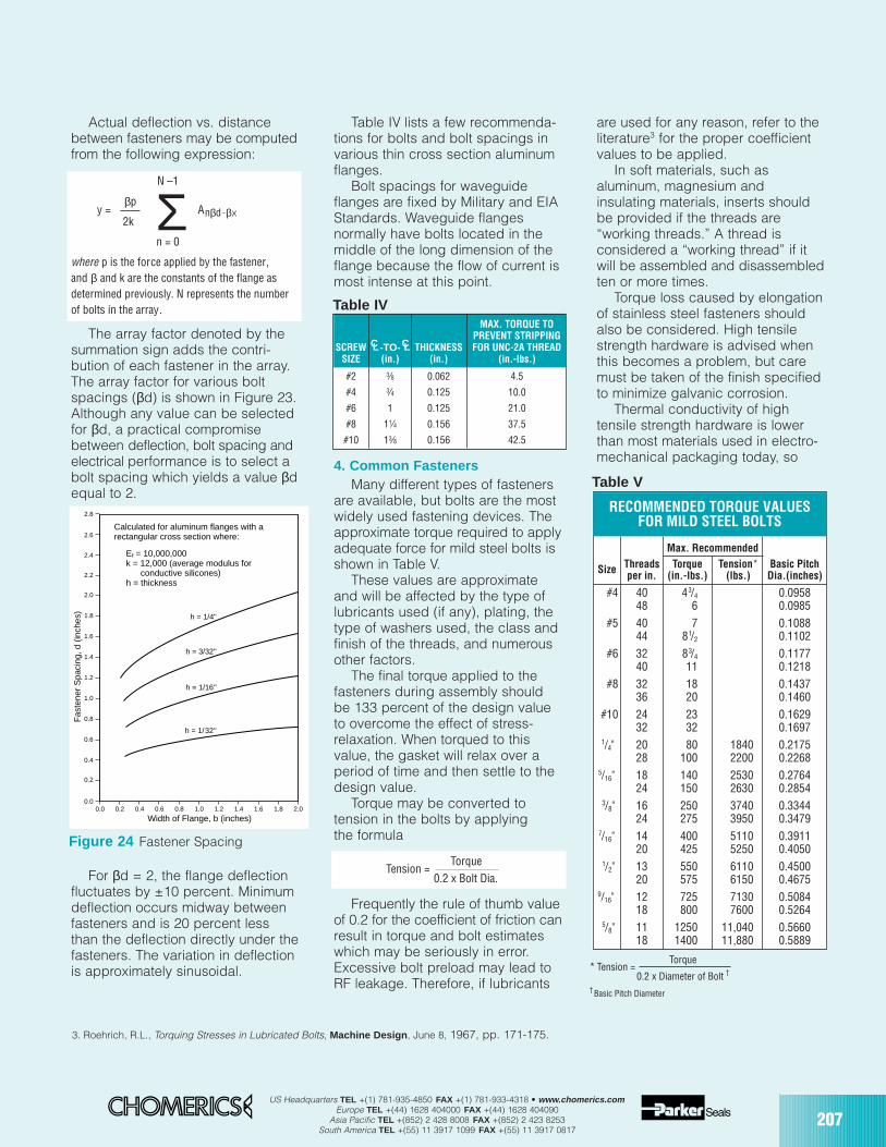
US Headquarters TEL +(1) 781-935-4850 FAX +(1) 781-933-4318 • www.chomerics.comEurope TEL +(44) 1628 404000 FAX +(44) 1628 404090
Asia Pacific TEL +(852) 2 428 8008 FAX +(852) 2 423 8253South America TEL +(55) 11 3917 1099 FAX +(55) 11 3917 0817
207
Actual deflection vs. distancebetween fasteners may be computedfrom the following expression:
N –1
y =βp
Anβd–βx2k
n = 0
where p is the force applied by the fastener,and β and k are the constants of the flange asdetermined previously. N represents the numberof bolts in the array.
The array factor denoted by thesummation sign adds the contri-bution of each fastener in the array.The array factor for various boltspacings (βd) is shown in Figure 23.Although any value can be selectedfor βd, a practical compromisebetween deflection, bolt spacing andelectrical performance is to select abolt spacing which yields a value βdequal to 2.
For βd = 2, the flange deflectionfluctuates by ±10 percent. Minimumdeflection occurs midway betweenfasteners and is 20 percent lessthan the deflection directly under thefasteners. The variation in deflectionis approximately sinusoidal.
Table IV lists a few recommenda-tions for bolts and bolt spacings invarious thin cross section aluminumflanges.
Bolt spacings for waveguideflanges are fixed by Military and EIAStandards. Waveguide flangesnormally have bolts located in themiddle of the long dimension of theflange because the flow of current ismost intense at this point.
4. Common FastenersMany different types of fasteners
are available, but bolts are the mostwidely used fastening devices. Theapproximate torque required to applyadequate force for mild steel bolts isshown in Table V.
These values are approximateand will be affected by the type oflubricants used (if any), plating, thetype of washers used, the class andfinish of the threads, and numerousother factors.
The final torque applied to thefasteners during assembly shouldbe 133 percent of the design valueto overcome the effect of stress-relaxation. When torqued to thisvalue, the gasket will relax over aperiod of time and then settle to thedesign value.
Torque may be converted totension in the bolts by applyingthe formula
Tension =Torque
0.2 x Bolt Dia.
Frequently the rule of thumb valueof 0.2 for the coefficient of friction canresult in torque and bolt estimateswhich may be seriously in error.Excessive bolt preload may lead toRF leakage. Therefore, if lubricants
are used for any reason, refer to theliterature3 for the proper coefficientvalues to be applied.
In soft materials, such asaluminum, magnesium andinsulating materials, inserts shouldbe provided if the threads are“working threads.” A thread isconsidered a “working thread” if itwill be assembled and disassembledten or more times.
Torque loss caused by elongationof stainless steel fasteners shouldalso be considered. High tensilestrength hardware is advised whenthis becomes a problem, but caremust be taken of the finish specifiedto minimize galvanic corrosion.
Thermal conductivity of hightensile strength hardware is lowerthan most materials used in electro-mechanical packaging today, so
MAX. TORQUE TOPREVENT STRIPPING
SCREW -TO- THICKNESS FOR UNC-2A THREADSIZE (in.) (in.) (in.-lbs.)
#2 3⁄8 0.062 4.5
#4 3⁄4 0.125 10.0
#6 1 0.125 21.0
#8 11⁄4 0.156 37.5
#10 13⁄8 0.156 42.5
Σ
CL CL
0.00.0 0.2 0.4 0.6 0.8 1.0 1.2 1.4 1.6 1.8 2.0
0.4
0.2
0.6
0.8
1.0
1.2
1.4
1.6
1.8
2.0
2.2
2.4
2.6
2.8
Calculated for aluminum flanges with arectangular cross section where:
Ef = 10,000,000k = 12,000 (average modulus for conductive silicones)h = thickness
h = 1/32"
h = 1/16"
h = 3/32"
h = 1/4"
Fas
tene
r S
paci
ng, d
(in
ches
)
Width of Flange, b (inches)
Figure 24 Fastener Spacing
Table IV
3. Roehrich, R.L., Torquing Stresses in Lubricated Bolts, Machine Design , June 8, 1967, pp. 171-175.
Max. Recommended
Size Threads Torque Tension* Basic Pitchper in. (in.-lbs.) (lbs.) Dia.(inches)
#4 40 43/4 0.095848 6 0.0985
#5 40 7 0.108844 81/2 0.1102
#6 32 83/4 0.117740 11 0.1218
#8 32 18 0.143736 20 0.1460
#10 24 23 0.162932 32 0.1697
1/4" 20 80 1840 0.217528 100 2200 0.2268
5/16" 18 140 2530 0.276424 150 2630 0.2854
3/8" 16 250 3740 0.334424 275 3950 0.3479
7/16" 14 400 5110 0.391120 425 5250 0.4050
1/2" 13 550 6110 0.450020 575 6150 0.4675
9/16" 12 725 7130 0.508418 800 7600 0.5264
5/8" 11 1250 11,040 0.566018 1400 11,880 0.5889
* Tension =Torque
0.2 x Diameter of Bolt †
† Basic Pitch Diameter
RECOMMENDED TORQUE VALUESFOR MILD STEEL BOLTS
Table V
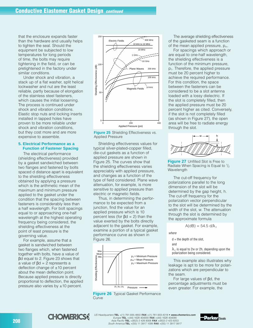
208US Headquarters TEL +(1) 781-935-4850 FAX +(1) 781-933-4318 • www.chomerics.com
Europe TEL +(44) 1628 404000 FAX +(44) 1628 404090Asia Pacific TEL +(852) 2 428 8008 FAX +(852) 2 423 8253
South America TEL +(55) 11 3917 1099 FAX +(55) 11 3917 0817
that the enclosure expands fasterthan the hardware and usually helpsto tighten the seal. Should theequipment be subjected to lowtemperatures for long periodsof time, the bolts may requiretightening in the field, or can bepretightened in the factory undersimilar conditions.
Under shock and vibration, astack up of a flat washer, split helicallockwasher and nut are the leastreliable, partly because of elongationof the stainless steel fasteners,which causes the initial loosening.The process is continued undershock and vibration conditions.Elastic stop nuts and locking insertsinstalled in tapped holes haveproven to be more reliable undershock and vibration conditions,but they cost more and are moreexpensive to assemble.
5. Electrical Performance as a Function of Fastener SpacingThe electrical performance
(shielding effectiveness) providedby a gasket sandwiched betweentwo flanges and fastened by boltsspaced d distance apart is equivalentto the shielding effectivenessobtained by applying a pressurewhich is the arithmetic mean of themaximum and minimum pressureapplied to the gasket under thecondition that the spacing betweenfasteners is considerably less thana half wavelength. For bolt spacingsequal to or approaching one-halfwavelength at the highest operatingfrequency being considered, theshielding effectiveness at thepoint of least pressure is thegoverning value.
For example, assume that agasket is sandwiched betweentwo flanges which, when fastenedtogether with bolts, have a value ofβd equal to 2. Figure 23 shows thata value of βd = 2 represents adeflection change of ±10 percentabout the mean deflection point.Because applied pressure is directlyproportional to deflection, the appliedpressure also varies by ±10 percent.
Shielding effectiveness values fortypical silver-plated-copper filled,die-cut gaskets as a function ofapplied pressure are shown inFigure 25. The curves show thatthe shielding effectiveness variesappreciably with applied pressure,and changes as a function of thetype of field considered. Plane waveattenuation, for example, is moresensitive to applied pressure thanelectric or magnetic fields.
Thus, in determining the perfor-mance to be expected from ajunction, find the value for anapplied pressure which is 10percent less (for βd = 2) than thevalue exerted by the bolts directlyadjacent to the gasket. For example,examine a portion of a typical gasketperformance curve as shown inFigure 26.
The average shielding effectivenessof the gasketed seam is a functionof the mean applied pressure, pm.
For spacings which approach orare equal to one-half wavelength,the shielding effectiveness is afunction of the minimum pressure,p1. Therefore, the applied pressuremust be 20 percent higher toachieve the required performance.For this condition, the spacebetween the fasteners can beconsidered to be a slot antennaloaded with a lossy dielectric. Ifthe slot is completely filled, thenthe applied pressure must be 20percent higher as cited. Conversely,if the slot is not completely filled(as shown in Figure 27), the openarea will be free to radiate energythrough the slot.
The cut-off frequency forpolarizations parallel to the longdimension of the slot will bedetermined by the gap height, h.The cut-off frequency for thepolarization vector perpendicularto the slot will be determined by thewidth of the slot, w. The attenuationthrough the slot is determined bythe approximate formula
A(dB) = 54.5 d/λ c
where
d = the depth of the slot,andλc is equal to 2w or 2h, depending upon thepolarization being considered.
This example also illustrates whyleakage is apt to be more for polari-zations which are perpendicular tothe seam.
For large values of βd, thepercentage adjustments must beeven greater. For example, the
20000
50
100
150
400
Magnetic Fields
Plane Waves
Electric Fields
Shi
eldi
ng E
ffect
iven
ess
(dB
)
Applied Pressure (psi)
10 kHz to 10 MHz
200 kHz
100 kHz
14 kHz
18 MHz
1 GHz
10 GHz
400 MHz
Figure 25 Shielding Effectiveness vs.Applied Pressure
Figure 26 Typical Gasket PerformanceCurve
p1 = Minimum Pressurepm = Mean Pressure p2 = Maximum Pressure
Pressure p1 pm p2
Max.Mean
Min.
Shi
eldi
ng E
ffect
iven
ess
Figure 27 Unfilled Slot is Free toRadiate When Spacing is Equal to 1/2Wavelength
w h
Conductive Elastomer Gasket Design continued

US Headquarters TEL +(1) 781-935-4850 FAX +(1) 781-933-4318 • www.chomerics.comEurope TEL +(44) 1628 404000 FAX +(44) 1628 404090
Asia Pacific TEL +(852) 2 428 8008 FAX +(852) 2 423 8253South America TEL +(55) 11 3917 1099 FAX +(55) 11 3917 0817
209
percentage increase required tosatisfy βd = 3 is 64 percent. It isdesirable, therefore, that βd shouldbe kept as small as possible. Thiscan be achieved by using stiff flangesor spacing bolts closer together.
Designing a Solid-OConductive ElastomerGasket-in-a-Groove
The solid-O profile is the mostoften specified conductive elastomerEMI gasket for several key reasons.Compared to other solid crosssections, it offers the widest deflectionrange to compensate for poorlytoleranced mating surfaces and toprovide reliable EMI shielding andpressure sealing. It can be installedin a relatively small space, and isthe most easily installed and manu-factured. It also tends to be lessprone to damage, due to the absenceof angles, corners or other crosssection appendages.
The “gasket-in-a-groove” designoffers five significant advantagesover surface-mounted EMI gaskets:
1. Superior shielding , due tosubstantial metal-to-metal contactachieved when the mating surfacesare bolted together and “bottomout”. (Flat die-cut gaskets preventmetal-to-metal contact betweenmating flange members, whichreduces EMI shielding performance– especially in low frequencymagnetic fields.)
2. Positive control over sealingperformance . Controlling the size ofthe gasket and groove can ensurethat required shielding and sealingare achieved with less carefulassembly than is required for flatgaskets. In other words, the gasket-in-a-groove is more foolproof.
3. Built-in compression stopprovided by the groove eliminatesthe risk of gasket damage due toexcessive compression.
4. A gasket retention mechanismcan be provided by the groove,eliminating the need for adhesivesor mounting frames.
5. High current-handlingcharacteristics of the metal-to-metal flange design improves theEMP and lightning protection offeredby an enclosure.
This section presents the methodfor calculating groove and gasketdimensions which will permit theshielding system to function underworst-case tolerance conditions.Adherence to these generalguidelines will result in optimumshielding and sealing for typicalelectronics “boxes”. It should beunderstood that they may not besuitable for designing shielding forsheet metal cabinets, doors, roomsor other large, unconventionalenclosures.
Important Notes: The guidelinespresented here are intended toconsider only “solid O” gasket crosssections. The calculations for hollowO, solid and hollow D, and customgasket cross sections differ fromthese guidelines in several key areas.
Chomerics generally does notrecommend bonding solid O gasketsin grooves. If for some reason yourdesign requires gasket retention,contact Chomerics’ ApplicationsEngineering Department for specificrecommendations, since the use ofadhesives, dove-tailed grooves or“friction-fit” techniques requirespecial design considerations notcovered here.
Extreme design requirements orunusually demanding specificationsare also beyond the scope of theguidelines presented here. Exampleswould include critical specificationsfor pressure sealing, exceptionallyhigh levels of EMI shielding, excep-tional resistance to corrosion, harshchemicals, high temperatures,heavy vibration, or unusual mountingand assembly considerations.
Mechanical ConsiderationsCauses of Seal Failure
In order to produce a gasket-in-a-groove system which will not fail, the
designer must consider threemechanical causes of seal failure:
gasket over-deflection andassociated damage (see Figure28d)gasket under-deflection andloss of seal (see Figure 28f)groove over-fill, which candestroy the gasket (see Figure28e).
Designing to avoid these problemsis made more complicated by theeffects of:
worst-case tolerance conditions
deformation of the cover(cover bowing)poor fit of mating surfaces.
The key to success involvesselection of the appropriate gasketsize and material, and careful designof the corresponding groove.Deflection Limits
In nearly every solid-O appli-cation, Chomerics recommends aminimum deflection of 10% of gasketdiameter. This includes adjustmentsfor all worst-case tolerances of boththe gasket and groove, coverbowing, and lack of conformitybetween mating surfaces. Werecommend a maximum gasketdeflection of 25% of gasket diameter,considering all gasket and groovetolerances.
Although sometimes modifiedto accommodate application pecu-liarities, these limits have beenestablished to allow for stressrelaxation, aging, compression set,elastic limits, thermal expansion, etc.Maximum Groove Fill
Solid elastomer gaskets (asopposed to foam rubber gaskets)seal by changing shape to conformto mating surfaces. They cannotchange volume. The recommendedlimit is 100% groove fill under worst-case tolerances of both gasket andgroove. The largest gasket crosssectional area must fit into the smallestcross sectional groove area.
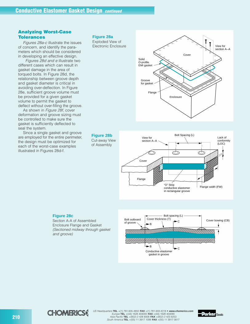
210US Headquarters TEL +(1) 781-935-4850 FAX +(1) 781-933-4318 • www.chomerics.com
Europe TEL +(44) 1628 404000 FAX +(44) 1628 404090Asia Pacific TEL +(852) 2 428 8008 FAX +(852) 2 423 8253
South America TEL +(55) 11 3917 1099 FAX +(55) 11 3917 0817
Figure 28cSection A-A of AssembledEnclosure Flange and Gasket(Sectioned midway through gasketand groove)
Bolt outboardof groove
Cover thickness (T)
Conductive elastomergasket in groove
Cover bowing (CB)
B
B
C
C
Bolt spacing (L)
Analyzing Worst-CaseTolerances
Figures 28a-c illustrate the issuesof concern, and identify the para-meters which should be consideredin developing an effective design.
Figures 28d and e illustrate twodifferent cases which can result ingasket damage in the area oftorqued bolts. In Figure 28d, therelationship between groove depthand gasket diameter is critical inavoiding over-deflection. In Figure28e, sufficient groove volume mustbe provided for a given gasketvolume to permit the gasket todeflect without over-filling the groove.
As shown in Figure 28f, coverdeformation and groove sizing mustbe controlled to make sure thegasket is sufficiently deflected toseal the system.
Since a single gasket and grooveare employed for the entire perimeter,the design must be optimized foreach of the worst-case examplesillustrated in Figures 28d-f.
Figure 28aExploded View ofElectronic Enclosure View for
section A–A
SolidO-profileEMI gasket
Groovefor gasket
Flange
Enclosure
Cover
View forsection A–A
Bolt Spacing (L)Lack ofconformity(LOC)
Flange width (FW) “O” Stripconductive elastomerin rectangular groove
Cover
Flange
Figure 28bCut-away View of Assembly
Conductive Elastomer Gasket Design continued
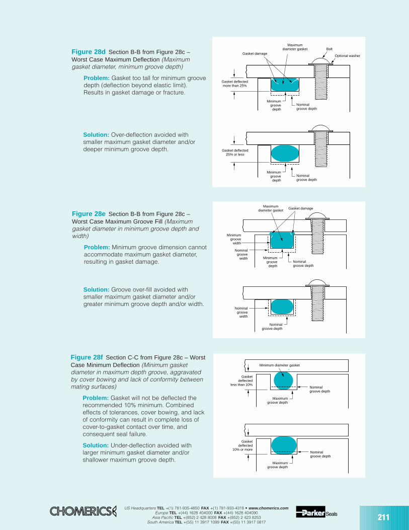
US Headquarters TEL +(1) 781-935-4850 FAX +(1) 781-933-4318 • www.chomerics.comEurope TEL +(44) 1628 404000 FAX +(44) 1628 404090
Asia Pacific TEL +(852) 2 428 8008 FAX +(852) 2 423 8253South America TEL +(55) 11 3917 1099 FAX +(55) 11 3917 0817
211
Figure 28d Section B-B from Figure 28c –Worst Case Maximum Deflection (Maximumgasket diameter, minimum groove depth)
Problem: Gasket too tall for minimum groovedepth (deflection beyond elastic limit).Results in gasket damage or fracture.
Figure 28e Section B-B from Figure 28c –Worst Case Maximum Groove Fill (Maximumgasket diameter in minimum groove depth andwidth)
Problem: Minimum groove dimension cannotaccommodate maximum gasket diameter,resulting in gasket damage.
Figure 28f Section C-C from Figure 28c – WorstCase Minimum Deflection (Minimum gasketdiameter in maximum depth groove, aggravatedby cover bowing and lack of conformity betweenmating surfaces)
Problem: Gasket will not be deflected therecommended 10% minimum. Combinedeffects of tolerances, cover bowing, and lackof conformity can result in complete loss ofcover-to-gasket contact over time, andconsequent seal failure.
Solution: Under-deflection avoided withlarger minimum gasket diameter and/orshallower maximum groove depth.
Maximumdiameter gasket Bolt
Optional washer
Minimumgroovedepth
Nominalgroove depth
Gasket deflectedmore than 25%
Gasket damage
Minimumgroovedepth
Nominalgroove depth
Gasket deflected25% or less
Maximumdiameter gasket
Minimumgroove
width
Minimumgroovedepth
Nominalgroove depth
Nominalgroove
width
Nominalgroove
width
Gasket damage
Nominalgroove depth
Maximumgroove depth
Gasketdeflected
less than 10%
Minimum diameter gasket
Nominalgroove depth
Maximumgroove depth
Gasketdeflected
10% or moreNominalgroove depth
Solution: Over-deflection avoided withsmaller maximum gasket diameter and/ordeeper minimum groove depth.
Solution: Groove over-fill avoided withsmaller maximum gasket diameter and/orgreater minimum groove depth and/or width.
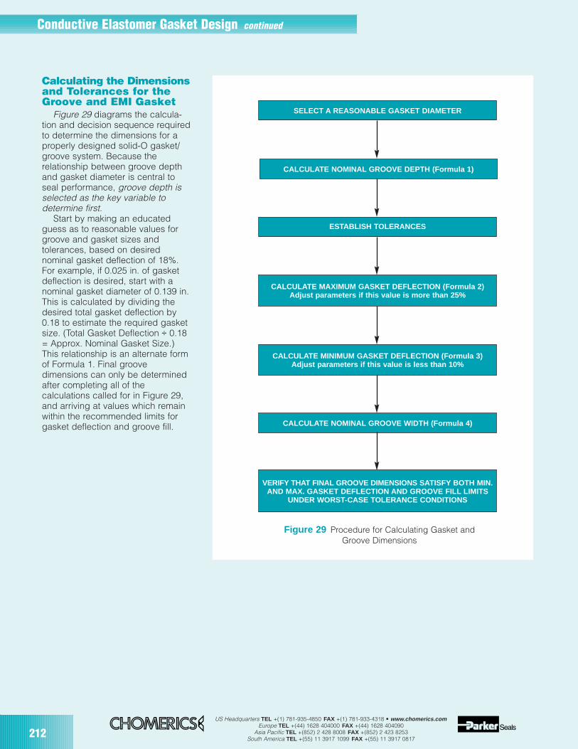
212US Headquarters TEL +(1) 781-935-4850 FAX +(1) 781-933-4318 • www.chomerics.com
Europe TEL +(44) 1628 404000 FAX +(44) 1628 404090Asia Pacific TEL +(852) 2 428 8008 FAX +(852) 2 423 8253
South America TEL +(55) 11 3917 1099 FAX +(55) 11 3917 0817
Calculating the Dimensionsand Tolerances for theGroove and EMI Gasket
Figure 29 diagrams the calcula-tion and decision sequence requiredto determine the dimensions for aproperly designed solid-O gasket/groove system. Because therelationship between groove depthand gasket diameter is central toseal performance, groove depth isselected as the key variable todetermine first.
Start by making an educatedguess as to reasonable values forgroove and gasket sizes andtolerances, based on desirednominal gasket deflection of 18%.For example, if 0.025 in. of gasketdeflection is desired, start with anominal gasket diameter of 0.139 in.This is calculated by dividing thedesired total gasket deflection by0.18 to estimate the required gasketsize. (Total Gasket Deflection ÷ 0.18= Approx. Nominal Gasket Size.)This relationship is an alternate formof Formula 1. Final groovedimensions can only be determinedafter completing all of thecalculations called for in Figure 29,and arriving at values which remainwithin the recommended limits forgasket deflection and groove fill.
Figure 29 Procedure for Calculating Gasket and Groove Dimensions
SELECT A REASONABLE GASKET DIAMETER
CALCULATE NOMINAL GROOVE DEPTH (Formula 1)
ESTABLISH TOLERANCES
CALCULATE MAXIMUM GASKET DEFLECTION (Formula 2)Adjust parameters if this value is more than 25%
CALCULATE NOMINAL GROOVE WIDTH (Formula 4)
CALCULATE MINIMUM GASKET DEFLECTION (Formula 3)Adjust parameters if this value is less than 10%
VERIFY THAT FINAL GROOVE DIMENSIONS SA TISFY BOTH MIN.AND MAX. GASKET DEFLECTION AND GROOVE FILL LIMITS
UNDER WORST-CASE TOLERANCE CONDITIONS
Conductive Elastomer Gasket Design continued

US Headquarters TEL +(1) 781-935-4850 FAX +(1) 781-933-4318 • www.chomerics.comEurope TEL +(44) 1628 404000 FAX +(44) 1628 404090
Asia Pacific TEL +(852) 2 428 8008 FAX +(852) 2 423 8253South America TEL +(55) 11 3917 1099 FAX +(55) 11 3917 0817
213
Formulas (see definition of terms at right)
1. Nominal Groove DepthGrDnom = 0.82 GaDnom
2. Maximum Gasket Deflection(Worst Case, expressed as a % of gasket diameter)
GaDfmax = 100[ (GaDnom + GaT) – (GrDnom – GrDT)](GaDnom+ GaT)
3. Minimum Gasket Deflection(Worst Case, expressed as a % of gasket diameter)
a. GaDfmin = 100[ (GaDnom – GaT) – (GrDnom + GrDT) – CB – LOC ](GaDnom– GaT)
where
b. CB = GDF x L4
max
FWmin x T3min x E x 32
(Note: Formula must be adjusted when using metric units)
and
c. LOC = 0.001 in. for machined sur faces with surface roughness of 32-64 µin. RMS.
(For discussion, see Terms.)
4. Nominal Groove Width
a. GaA max = 0.7854* (GaDnom + GaT)2
b. GrWmin =GaAmax
GrDmin
c. GrWnom= GrWmin + GrWT
*Note: 0.7854 =π4
TermsAll values may be calculated in inches or mmunless otherwise indicated.GaAmax – Maximum gasket cross section area(in2 or mm2)GaDnom – Nominal gasket diameterGaT – Gasket tolerance (difference between max.and nom. or min. and nom.)GrWmin – Minimum groove widthGrWT – Groove width toleranceGrWnom – Nominal groove widthGrDmin – Minimum groove depthGrDnom – Nominal groove depthGrDT – Groove depth tolerance (differencebetween max. and nom. or min. and nom.)GaDfmax – Maximum gasket deflection (%)GaDfmin – Minimum gasket deflection (%)Lmax – Maximum bolt spacingFWmin – Minimum flange widthTmin – Minimum cover thicknessGDF – Gasket deflection force (ppi or Newtonsper meter).Note: For the purpose of this guide, the GDF valueshould represent the worst-case minimum gasketdeflection arising from cover bowing. For example,the GDF is taken at 10% deflection for thecalculation in Formula 3b.E – Young’s modulus. (For aluminum, use 1 x 10⁷
psi, or 7 x 10⁵ kg/cm2.)CB – Cover bowing, generally calculated bymodeling the elastic deformation of the cover as auniformly loaded beam with two fixed supports.(The moment of inertia of the cover is modeled as arectangular beam, the “height” of which is taken tobe equal to the cover thickness, while “width” isconsidered equal to flange width. The moment ofinertia can be adjusted for cover configurationsother than flat. Refer to an engineering handbookfor the necessary revisions to Formula 3b.) Anassumption is made that one side of a cover/flangeinterface is infinitely stiff, typically the flange. If thisis not essentially true, elastic deformation of each iscomputed as though the other were infinitely stiff,and the two values combined.LOC – Lack of conformity, the measure of themismatch between two mating surfaces whenbolted together, expressed in inches. Experiencehas shown that machined surfaces with a surfaceroughness of 32-64 µin. RMS exhibit an LOC of0.001 in. It is left to the engineer’s judgment todetermine LOC for other surfaces. LOC can bedetermined empirically from measurements madeof actual hardware. In this guide, LOC applies onlyto the surfaces which form the EMI shieldinginterface.
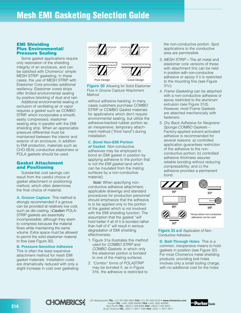
214US Headquarters TEL +(1) 781-935-4850 FAX +(1) 781-933-4318 • www.chomerics.com
Europe TEL +(44) 1628 404000 FAX +(44) 1628 404090Asia Pacific TEL +(852) 2 428 8008 FAX +(852) 2 423 8253
South America TEL +(55) 11 3917 1099 FAX +(55) 11 3917 0817
EMI ShieldingPlus Environmental/Pressure Sealing
Some gasket applications requireonly restoration of the shieldingintegrity of an enclosure, and canbe satisfied with Chomerics’ simpleMESH STRIP gasketing. In thesecases, the use of MESH STRIP withElastomer Core provides additionalresiliency. Elastomer cored stripsoffer limited environmental sealingby positive blocking of dust and rain.
Additional environmental sealing orexclusion of ventilating air or vaporrequires a gasket such as COMBOSTRIP, which incorporates a smooth,easily compressed, elastomersealing strip in parallel with the EMIshielding strip. When an appreciablepressure differential must bemaintained between the interior andexterior of an enclosure, in additionto EMI protection, materials such asCHO-SEAL conductive elastomers orPOLA gaskets should be used.
Gasket Attachmentand Positioning
Substantial cost savings canresult from the careful choice ofgasket attachment or positioningmethod, which often determinesthe final choice of material.
A. Groove Capture This method isstrongly recommended if a groovecan be provided at relatively low cost,such as die-casting. (Caution: POLA-STRIP gaskets are essentiallyincompressible, although they seemto compress because the materialflows while maintaining the samevolume. Extra space must be allowedto permit the solid elastomer materialto flow (see Figure 30).B. Pressure-Sensitive AdhesiveThis is often the least expensiveattachment method for mesh EMIgasket materials. Installation costsare dramatically reduced with only aslight increase in cost over gasketing
without adhesive backing. In manycases customers purchase COMBOSTRIP or COMBO Gasket materialsfor applications which don’t requireenvironmental sealing, but utilize theadhesive-backed rubber portion asan inexpensive, temporary attach-ment method (“third hand”) duringinstallation.
C. Bond Non-EMI Portionof Gasket Non-conductiveadhesives may be employed tobond an EMI gasket in position byapplying adhesive to the portion thatis not the EMI gasket (and whichcan be insulated from the matingsurfaces by a non-conductivematerial).
Note: When specifying non-conductive adhesive attachment,applicable drawings and standardprocedures for production personnelshould emphasize that the adhesiveis to be applied only to the portionof the gasket which is not involvedwith the EMI shielding function. Theassumption that the gasket “willhold better if all of it is bonded ratherthan half of it” will result in seriousdegradation of EMI shieldingeffectiveness.1. Figure 31a illustrates this method
used for COMBO STRIP andCOMBO Gaskets, in which onlythe elastomer portion is bondedto one of the mating surfaces.
2. “Combo“ forms of POLASTRIPmay be bonded if, as in Figure31b, the adhesive is restricted to
the non-conductive portion. Spotapplications to the conductivearea are permissible.
3. MESH STRIP – The all metal andelastomer core versions of thesewith attachment fins can be heldin position with non-conductiveadhesive or epoxy if it is restrictedto the mounting fins (see Figure31c).
4. Frame Gasketing can be attachedwith a non-conductive adhesive orepoxy restricted to the aluminumextrusion (see Figure 31d).However, most Frame Gasketsare attached mechanically withfasteners.
5. Dry Back Adhesive for NeopreneSponge COMBO Gaskets –Factory-applied solvent-activatedadhesive is recommended forseveral reasons: a) controlledapplication guarantees restrictionof the adhesive to the non-conductive portion; b) controlledadhesive thickness assuresreliable bonding without reducingcompressibility; and c) theadhesive provides a permanentbond.
D. Bolt-Through Holes This is acommon, inexpensive means to holdgaskets in position (see Figure 32).For most Chomerics metal shieldingproducts, providing bolt holesinvolves only a small tooling charge,with no additional cost for the holes
Figure 30 Allowing for Solid ElastomerFlow in Groove Capture AttachmentMethod
Good DesignPoor Design
(a)*
(b)*
(c)*
(d)*
(c)*
*Areas where non-conductive adhesives can be used
Figure 31 a-d Application of Non-Conductive Adhesive
Mesh EMI Gasketing Selection Guide
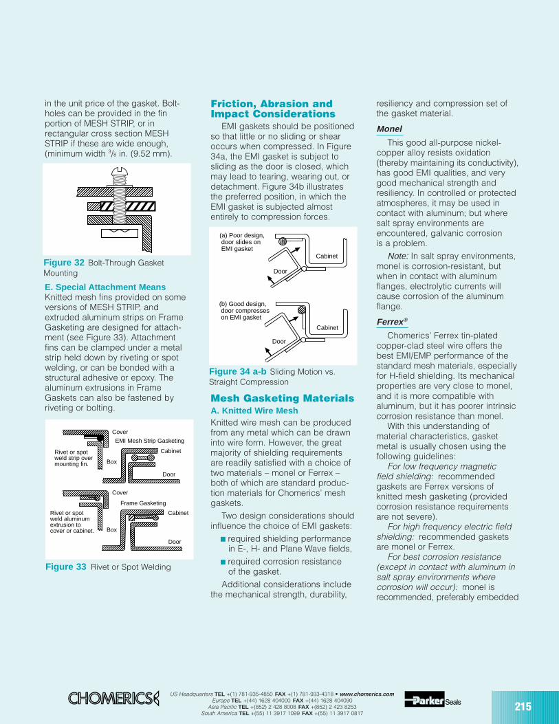
US Headquarters TEL +(1) 781-935-4850 FAX +(1) 781-933-4318 • www.chomerics.comEurope TEL +(44) 1628 404000 FAX +(44) 1628 404090
Asia Pacific TEL +(852) 2 428 8008 FAX +(852) 2 423 8253South America TEL +(55) 11 3917 1099 FAX +(55) 11 3917 0817
215
in the unit price of the gasket. Bolt-holes can be provided in the finportion of MESH STRIP, or inrectangular cross section MESHSTRIP if these are wide enough,(minimum width 3/8 in. (9.52 mm).
E. Special Attachment MeansKnitted mesh fins provided on someversions of MESH STRIP, andextruded aluminum strips on FrameGasketing are designed for attach-ment (see Figure 33). Attachmentfins can be clamped under a metalstrip held down by riveting or spotwelding, or can be bonded with astructural adhesive or epoxy. Thealuminum extrusions in FrameGaskets can also be fastened byriveting or bolting.
Friction, Abrasion andImpact Considerations
EMI gaskets should be positionedso that little or no sliding or shearoccurs when compressed. In Figure34a, the EMI gasket is subject tosliding as the door is closed, whichmay lead to tearing, wearing out, ordetachment. Figure 34b illustratesthe preferred position, in which theEMI gasket is subjected almostentirely to compression forces.
Mesh Gasketing MaterialsA. Knitted Wire MeshKnitted wire mesh can be producedfrom any metal which can be drawninto wire form. However, the greatmajority of shielding requirementsare readily satisfied with a choice oftwo materials – monel or Ferrex –both of which are standard produc-tion materials for Chomerics’ meshgaskets.
Two design considerations shouldinfluence the choice of EMI gaskets:
required shielding performancein E-, H- and Plane Wave fields,
required corrosion resistanceof the gasket.
Additional considerations includethe mechanical strength, durability,
resiliency and compression set ofthe gasket material.
Monel
This good all-purpose nickel-copper alloy resists oxidation(thereby maintaining its conductivity),has good EMI qualities, and verygood mechanical strength andresiliency. In controlled or protectedatmospheres, it may be used incontact with aluminum; but wheresalt spray environments areencountered, galvanic corrosionis a problem.
Note: In salt spray environments,monel is corrosion-resistant, butwhen in contact with aluminumflanges, electrolytic currents willcause corrosion of the aluminumflange.
Ferrex ®
Chomerics’ Ferrex tin-platedcopper-clad steel wire offers thebest EMI/EMP performance of thestandard mesh materials, especiallyfor H-field shielding. Its mechanicalproperties are very close to monel,and it is more compatible withaluminum, but it has poorer intrinsiccorrosion resistance than monel.
With this understanding ofmaterial characteristics, gasketmetal is usually chosen using thefollowing guidelines:
For low frequency magneticfield shielding: recommendedgaskets are Ferrex versions ofknitted mesh gasketing (providedcorrosion resistance requirementsare not severe).
For high frequency electric fieldshielding: recommended gasketsare monel or Ferrex.
For best corrosion resistance(except in contact with aluminum insalt spray environments wherecorrosion will occur): monel isrecommended, preferably embedded
Figure 32 Bolt-Through GasketMounting
Figure 33 Rivet or Spot Welding
Cabinet
Cabinet
Door
Door
Frame Gasketing
Box
Box
Cover
Cover
Rivet or spotweld aluminumextrusion tocover or cabinet.
Rivet or spotweld strip overmounting fin.
EMI Mesh Strip Gasketing
Figure 34 a-b Sliding Motion vs.Straight Compression
Door
Cabinet
(a) Poor design, door slides on EMI gasket
Door
Cabinet
(b) Good design, door compresses on EMI gasket
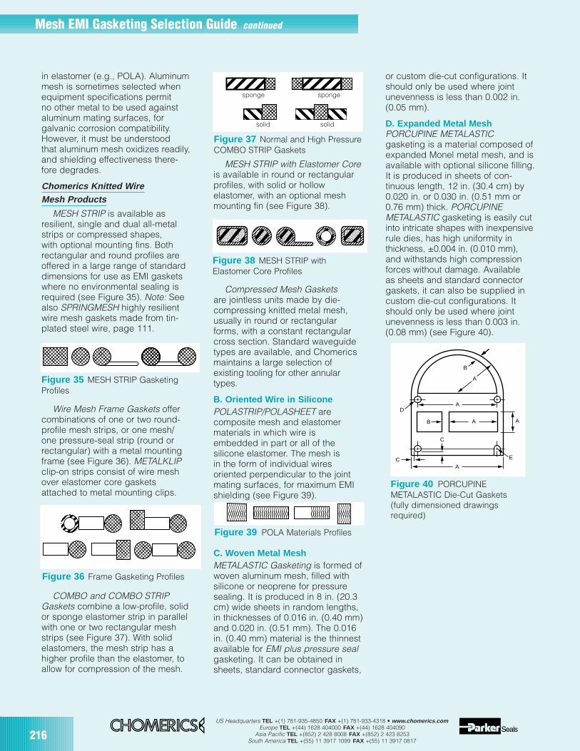
216US Headquarters TEL +(1) 781-935-4850 FAX +(1) 781-933-4318 • www.chomerics.com
Europe TEL +(44) 1628 404000 FAX +(44) 1628 404090Asia Pacific TEL +(852) 2 428 8008 FAX +(852) 2 423 8253
South America TEL +(55) 11 3917 1099 FAX +(55) 11 3917 0817
in elastomer (e.g., POLA). Aluminummesh is sometimes selected whenequipment specifications permitno other metal to be used againstaluminum mating surfaces, forgalvanic corrosion compatibility.However, it must be understoodthat aluminum mesh oxidizes readily,and shielding effectiveness there-fore degrades.
Chomerics Knitted WireMesh Products
MESH STRIP is available asresilient, single and dual all-metalstrips or compressed shapes,with optional mounting fins. Bothrectangular and round profiles areoffered in a large range of standarddimensions for use as EMI gasketswhere no environmental sealing isrequired (see Figure 35). Note: Seealso SPRINGMESH highly resilientwire mesh gaskets made from tin-plated steel wire, page 111.
Wire Mesh Frame Gaskets offercombinations of one or two round-profile mesh strips, or one mesh/one pressure-seal strip (round orrectangular) with a metal mountingframe (see Figure 36). METALKLIPclip-on strips consist of wire meshover elastomer core gasketsattached to metal mounting clips.
COMBO and COMBO STRIPGaskets combine a low-profile, solidor sponge elastomer strip in parallelwith one or two rectangular meshstrips (see Figure 37). With solidelastomers, the mesh strip has ahigher profile than the elastomer, toallow for compression of the mesh.
MESH STRIP with Elastomer Coreis available in round or rectangularprofiles, with solid or hollowelastomer, with an optional meshmounting fin (see Figure 38).
Compressed Mesh Gasketsare jointless units made by die-compressing knitted metal mesh,usually in round or rectangularforms, with a constant rectangularcross section. Standard waveguidetypes are available, and Chomericsmaintains a large selection ofexisting tooling for other annulartypes.
B. Oriented Wire in SiliconePOLASTRIP/POLASHEET arecomposite mesh and elastomermaterials in which wire isembedded in part or all of thesilicone elastomer. The mesh isin the form of individual wiresoriented perpendicular to the jointmating surfaces, for maximum EMIshielding (see Figure 39).
C. Woven Metal MeshMETALASTIC Gasketing is formed ofwoven aluminum mesh, filled withsilicone or neoprene for pressuresealing. It is produced in 8 in. (20.3cm) wide sheets in random lengths,in thicknesses of 0.016 in. (0.40 mm)and 0.020 in. (0.51 mm). The 0.016in. (0.40 mm) material is the thinnestavailable for EMI plus pressure sealgasketing. It can be obtained insheets, standard connector gaskets,
or custom die-cut configurations. Itshould only be used where jointunevenness is less than 0.002 in.(0.05 mm).
D. Expanded Metal MeshPORCUPINE METALASTICgasketing is a material composed ofexpanded Monel metal mesh, and isavailable with optional silicone filling.It is produced in sheets of con-tinuous length, 12 in. (30.4 cm) by0.020 in. or 0.030 in. (0.51 mm or0.76 mm) thick. PORCUPINEMETALASTIC gasketing is easily cutinto intricate shapes with inexpensiverule dies, has high uniformity inthickness, ±0.004 in. (0.010 mm),and withstands high compressionforces without damage. Availableas sheets and standard connectorgaskets, it can also be supplied incustom die-cut configurations. Itshould only be used where jointunevenness is less than 0.003 in.(0.08 mm) (see Figure 40).
Figure 39 POLA Materials Profiles
Figure 35 MESH STRIP GasketingProfiles
Figure 36 Frame Gasketing Profiles
Figure 37 Normal and High PressureCOMBO STRIP Gaskets
Figure 40 PORCUPINEMETALASTIC Die-Cut Gaskets(fully dimensioned drawingsrequired)
Figure 38 MESH STRIP with Elastomer Core Profiles
A
B
B AA
AD
C
C
A
E
sponge sponge
solid solid
Mesh EMI Gasketing Selection Guide continued
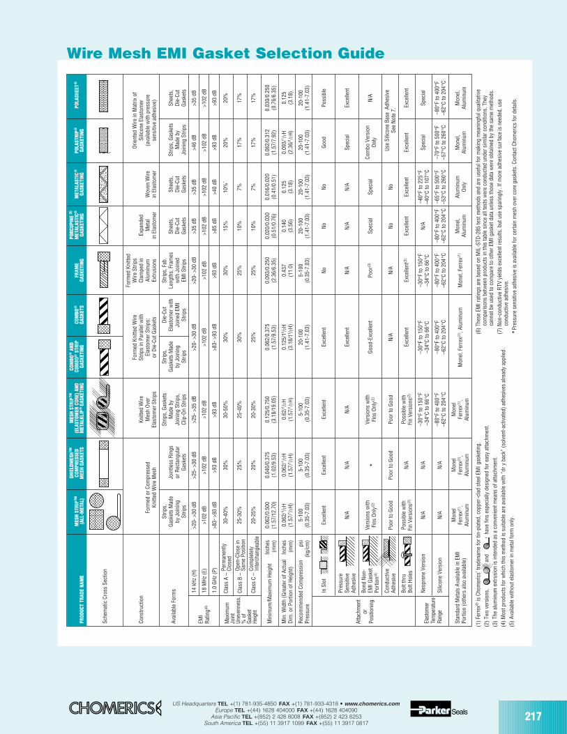
US Headquarters TEL +(1) 781-935-4850 FAX +(1) 781-933-4318 • www.chomerics.comEurope TEL +(44) 1628 404000 FAX +(44) 1628 404090
Asia Pacific TEL +(852) 2 428 8008 FAX +(852) 2 423 8253South America TEL +(55) 11 3917 1099 FAX +(55) 11 3917 0817
217
Wire Mesh EMI Gasket Selection Guide
Sche
mat
ic C
ross
Sec
tion
Form
ed K
nitte
dFo
rmed
Kni
tted
Wire
Wire
Str
ips
Orie
nted
Wire
in M
atrix
of
Cons
truc
tion
Knitt
ed W
ireSt
rips
in P
aral
lel w
ithCl
ampe
d in
Expa
nded
Silic
one
Elas
tom
erFo
rmed
or C
ompr
esse
dM
esh
Ove
rEl
asto
mer
Str
ips;
Alum
inum
Met
alW
oven
Wire
(ava
ilabl
e w
ith p
ress
ure
Knitt
ed W
ire M
esh
Elas
tom
er S
trip
sor
Die
-Cut
Gas
kets
Extr
usio
nsin
Ela
stom
erin
Ela
stom
erse
nsiti
ve a
dhes
ive)
Strip
s,St
rips,
Gas
kets
Strip
s,D
ie-C
utSt
rips,
Fab
.G
aske
ts M
ade
Join
tless
Rin
gsM
ade
byG
aske
ts M
ade
Elas
tom
er w
ithLe
ngth
s, F
ram
esSh
eets
,Sh
eets
,St
rips,
Gas
kets
Shee
ts,
Avai
labl
e Fo
rms
by J
oini
ngor
Rec
tang
ular
Join
ing
Strip
s,by
Joi
ning
Join
ed E
MI
with
Joi
ned
Die
-Cut
Die
-Cut
Mad
e by
Die
-Cut
Strip
sG
aske
tsCl
ip-O
n St
rips
Strip
sSt
rips
EMI S
trip
sG
aske
tsG
aske
tsJo
inin
g St
rips
Gas
kets
14 k
Hz
(H)
>20-
>30
dB
>25-
>30
dB
>25-
>35
dB
>20-
>30
dB
>20-
>30
dB
>35
dB>3
5 dB
>46
dB>3
5 dB
18 M
Hz
(E)
>102
dB
>102
dB
>102
dB
>102
dB
>102
dB
>102
dB
>102
dB
>102
dB
>102
dB
1.0
GH
z (P
)>8
3- >
93 d
B>9
3 dB
>93
dB>8
3- >
93 d
B>9
3 dB
>85
dB>4
0 dB
>93
dB>9
3 dB
30-4
0%30
%30
-50%
30%
30%
15%
10%
`20
%20
%
25-3
0%25
%25
-40%
30%
25%
10%
7%17
%17
%
20-2
5%20
%20
-30%
25%
25%
10%
7%17
%17
%
Min
imum
/Max
imum
Hei
ght
Inch
es0.
062/
0.50
00.
040/
0.37
50.
125/
0.75
00.
062/
0.37
50.
093/
0.25
00.
020/
0.03
00.
016/
0.02
00.
062/
0.31
20.
030/
0.25
0(m
m)
(1.5
7/12
.70)
(1.0
2/9.
53)
(3.1
8/19
.05)
(1.5
7/9.
53)
(2.3
6/6.
35)
(0.5
1/0.
76)
(0.4
1/0.
51)
(1.5
7/7.
92)
(0.7
6/6.
35)
Min
. Wid
th (G
reat
er o
f Act
ual
Inch
es0.
062/
1 /2H
0.06
2/1 /2
H0.
62/1 /2
H0.
125/
11 /2H
0.43
70.
140
0.12
50.
093/
1 /2H
0.12
5D
im. o
r Por
tion
of H
eigh
t)(m
m)
(1.5
7/1 /2
H)
(1.5
7/1 /2
H)
(1.5
7/1 /2
H)
(3.1
8/11 /2
H)
(11.
0)(3
.56)
(3.1
8)(2
.36/
1 /2H
)(3
.18)
Rec
omm
ende
d Co
mpr
essi
onps
i5-
100
5-10
05-
100
20-1
005-
100
20-1
0020
-100
20-1
0020
-100
Pres
sure
(kg/
cm)
(0.3
5-7.
03)
(0.3
5-7.
03)
(0.3
5-7.
03)
(1.4
1-7.
03)
(0.3
5-7.
03)
(1.4
1-7.
03)
(1.4
1-7.
03)
(1.4
1-7.
03)
(1.4
1-7.
03)
In S
lot
Exce
llent
Exce
llent
Exce
llent
Exce
llent
No
No
No
Goo
dPo
ssib
le
Pres
sure
Sens
itive
N/A
N/A
N/A
Exce
llent
N/A
N/A
N/A
Spec
ial
Exce
llent
Adhe
sive
Bond
Non
-EM
I Gas
ket
Vers
ions
with
*Ve
rsio
ns w
ithG
ood-
Exce
llent
Poor
(3)
Spec
ial
Spec
ial
Com
bo V
ersi
onN
/APo
rtio
n(4)
Fins
Onl
y(2)
Fins
Onl
y(2)
Onl
y
Cond
uctiv
eU
se S
ilico
ne B
ase
Adh
esiv
eAd
hesi
vePo
or to
Goo
dPo
or to
Goo
dPo
or to
Goo
dN
/AN
/AN
oN
oSe
e N
ote
7.
Bolt
thru
Poss
ible
with
N/A
Poss
ible
with
Exce
llent
Exce
llent
(3)
Exce
llent
Exce
llent
Exce
llent
Exce
llent
Bolt
Hol
esFi
n Ve
rsio
ns(2
)Fi
n Ve
rsio
ns(2
)
Neo
pren
e Ve
rsio
nN
/AN
/A–3
0°F
to 1
50°F
–30°
F to
150
°F–3
0°F
to 1
50°F
N/A
–40°
F to
225
°FSp
ecia
lSp
ecia
l–3
4°C
to 6
6°C
–34°
C to
66°
C–3
4°C
to 6
6°C
–40°
C to
107
°C
Silic
one
Vers
ion
N/A
N/A
–80°
F to
400
°F–8
0°F
to 4
00°F
–80°
F to
400
°F–8
0°F
to 4
00°F
–65°
F to
500
°F–7
0°F
to 5
00°F
–80°
F to
400
°F–6
2°C
to 2
04°C
–62°
C to
204
°C–6
2°C
to 2
04°C
–62°
C to
204
°C–5
3°C
to 2
60°C
–57°
C to
260
°C–6
2°C
to 2
04°C
Stan
dard
Met
als
Avai
labl
e in
EM
IM
onel
Mon
elM
onel
Mon
el,
Alum
inum
Mon
el,
Mon
el,
Port
ion
(oth
ers
also
ava
ilabl
e)
Ferr
ex(1
) ,Fe
rrex
(1) ,
Ferr
ex(1
) ,M
onel
, Fer
rex(1
) , Al
umin
umM
onel
, Fer
rex(1
)
Alum
inum
Onl
yAl
umin
umAl
umin
umAl
umin
umAl
umin
umAl
umin
um
EMI
Rat
ing(6
)
Clas
s A
–Pe
rman
ently
Clos
ed
Clas
s B
–O
pen-
Clos
e in
Sam
e Po
sitio
n
Clas
s C
–Co
mpl
etel
yIn
terc
hang
eabl
e
Atta
chm
ent
orPo
sitio
ning
Elas
tom
erTe
mpe
ratu
reRa
nge
Max
imum
Join
tUn
even
ness
,%
of
Gask
etHe
ight
(1) F
erre
x®is
Cho
mer
ics’
trad
enam
e fo
r tin
-pla
ted,
cop
per-
clad
ste
el E
MIg
aske
ting.
(2) T
wo
vers
ions
,an
dha
ve fi
ns e
spec
ially
des
igne
d fo
r eas
y at
tach
men
t.(3
) The
alu
min
um e
xtru
sion
is in
tend
ed a
s a
conv
enie
nt m
eans
of a
ttach
men
t.(4
) Mos
t pro
duct
s fo
r whi
ch th
is m
etho
d is
sui
tabl
e ar
e av
aila
ble
with
“dr
y ba
ck”
(sol
vent
-act
ivat
ed) a
dhes
ives
alre
ady
appl
ied
.(5
) Ava
ilabl
e w
ithou
t ela
stom
er in
met
al fo
rm o
nly.
(6) T
hese
EM
I rat
ings
are
bas
ed o
n M
IL-S
TD-2
85 te
st m
etho
ds a
nd a
re u
sefu
l for
mak
ing
mea
ning
ful q
ualit
ativ
eco
mpa
rison
s be
twee
n pr
oduc
ts in
this
tabl
e si
nce
all t
ests
wer
e co
nduc
ted
unde
r sim
ilar c
ondi
tions
. The
yca
nnot
be
used
to c
ompa
re to
oth
er E
MI g
aske
t dat
a un
less
thos
e da
ta w
ere
obta
ined
by
the
sam
e m
etho
ds.
(7) N
on-c
ondu
ctiv
e R
TV y
ield
s ex
celle
nt re
sults
, but
use
spa
ringl
y. If
mor
e ad
hesi
ve s
urfa
ce is
nee
ded,
use
cond
uctiv
e ad
hesi
ve.
*Pre
ssur
e se
nsiti
ve a
dhes
ive
is a
vaila
ble
for c
erta
in m
esh
over
cor
e ga
sket
s. C
onta
ct C
hom
eric
s fo
r det
ails
.
SHIE
LDM
ESHTM
MES
H ST
RIPTM
COM
BO®
AND
PORC
UPIN
E(5
)
MES
H ST
RIPTM
COM
PRES
SED
(ELA
STOM
ER C
ORE)
AND
COM
BO®
STRI
PCO
MBO
®FR
AME
MET
ALAS
TIC®
MET
ALAS
TIC®
POLA
STRI
P®PO
LASH
EET®
PROD
UCT
TRAD
E NA
ME
(ALL
-MET
AL)
MES
H GA
SKET
SM
ETAL
KLIP
® G
ASKE
TING
GASK
ETIN
GGA
SKET
SGA
SKET
ING
GASK
ETIN
GGA
SKET
ING
GASK
ETIN
G
GASK
ETIN
G
218US Headquarters TEL +(1) 781-935-4850 FAX +(1) 781-933-4318 • www.chomerics.com
Europe TEL +(44) 1628 404000 FAX +(44) 1628 404090Asia Pacific TEL +(852) 2 428 8008 FAX +(852) 2 423 8253
South America TEL +(55) 11 3917 1099 FAX +(55) 11 3917 0817
ElectricalAbsorption Loss: Attenuation of anelectromagnetic wave or energyencountered in penetrating a shieldcaused by the induction of currentflow in the barrier and the resultingI2R loss. Usually stated in dB (decibels).
Ambient ElectromagneticEnvironment: That electromagneticfield level existing in an area andemanating from sources other thanthe system under test.
Attenuation: A reduction in energy.Attenuation occurs naturally duringwave travel through transmissionlines, waveguides, space or amedium such as water, or may beproduced intentionally by inserting anattenuator in a circuit or a shieldingabsorbing device in the path ofradiation. The degree of attenuationis expressed in decibels or decibelsper unit length.
Attenuator: An arrangement of fixedand/or variable resistive elementsused to attenuate a signal by adesired amount.
Cross Coupling: Coupling of thesignal from one channel to anotherwhere it becomes an undesired signal.
Conductivity: Capability of a materialto conduct electrical currents.
Decibel (dB): A convenient methodfor expressing voltage or power ratiosin logarithmic terms. The number ofsuch units of attenuation, N is
where
P1/P2 is a unitless power ratio. N can also beexpressed in terms of a voltage ratio E 1/E2 asfollows:
Degradation: An undesired changein the operational performance of atest specimen. Degradation of theoperation of a test specimen doesnot necessarily mean malfunction.
Depth of Penetration: Distancewhich a plane wave must travelthrough a shield to be attenuated 1/e,or approximately 37 percent of itsoriginal value. (Also called “skindepth”). It is a function of the shield’sconductivity and permeability and thewave’s frequency.
Electrical or E-Field: A field inducedby a high impedance source, such asa short dipole.
Electromagnetic Compatibility(EMC): A measure of an equipment’sability to neither radiate nor conductelectromagnetic energy, or to besusceptible to such energy fromother equipment or an externalelectromagnetic environment.
Electromagnetic Interference (EMI):Undesired conducted or radiatedelectrical disturbances, includingtransients, which can interfere withthe operation of electrical or electronicequipment. These disturbances canoccur anywhere in the electromagneticspectrum.
Emanation: Undesired electromag-netic energy radiated or conductedfrom a system.
Gasket-EMI: A material that is insertedbetween mating surfaces of anelectronic enclosure to provide lowresistance across the seam andthereby preserve current continuityof the enclosure.
Ground: A reference plane commonto all electronic, electrical,electro-mechanical systems and connectedto earth by means of a ground rod,ground grid, or other similar means.
Hertz: An international designationfor cycles per second (cps).
Insertion Loss: Measure ofimprovement in a seam, joint orshield by the addition of a conductivegasket. Usually stated in dB.
Interference: Any electromagneticphenomenon, signal or emission,man-made or natural, which causesor can cause an undesired response,malfunctioning or degradation ofperformance of electrical or electronicequipment.
Internal Loss: Attenuation of electro-magnetic energy by the reflectionand re-reflection of electromagneticwaves within a shield or a barrier.Usually stated in dB.
Magnetic or H-Field: An inductionfield caused predominantly by acurrent source. Also called a lowimpedance source, such as may begenerated by a loop antenna.
Malfunction: A change in theequipment’s normal characteristicswhich effectively destroys properoperation.
Permeability: The capability of amaterial to be magnetized at a givenrate. It is a non-linear property of boththe magnetic flux density and thefrequency of wave propagation.
Plane Wave: An electromagneticwave which exists at a distancegreater than a wavelength fromthe source, where the impedanceof the wave is nearly equal to theimpedance of free space – 377 ohms.
Radio Frequency (RF): Any frequencyat which coherent electromagneticradiation of energy is possible.Generally considered to be anyfrequency above 10 kHz.
Radio Frequency Interference (RFI):Used interchangeably with EMI. EMIis a later definition which includes theentire electromagnetic spectrum,whereas RFI is more restricted tothe radio frequency band, generallyconsidered to be between the limits10 kHz to 10 GHz.
Reflection Loss: Attenuation of theelectromagnetic wave or energycaused by impedance mismatchbetween the wave in air and the wavein metal.
Glossary of Terms
N (dB) =10 log P1
P2
N (dB) =20 log E1
E2

US Headquarters TEL +(1) 781-935-4850 FAX +(1) 781-933-4318 • www.chomerics.comEurope TEL +(44) 1628 404000 FAX +(44) 1628 404090
Asia Pacific TEL +(852) 2 428 8008 FAX +(852) 2 423 8253South America TEL +(55) 11 3917 1099 FAX +(55) 11 3917 0817
219
Relative Conductivity: Conductivityof the shield material relative to theconductivity of copper.
Relative Permeability: Magneticpermeability of the shield materialrelative to the permeability of freespace.
Shield: A metallic configurationinserted between a source and thedesired area of protection which hasthe capability to reduce the energylevel of a radiating electromagneticfield by reflecting and absorbing theenergy contained in the field.
Shielding Effectiveness: A measureof the reduction or attenuation inelectromagnetic field strength at apoint in space caused by the insertionof a shield between the source andthat point. Usually stated in dB.
Shielding Increase: The differenceof an electromagnetic field amplitudeemanating through a seam (measuredunder fixed test conditions) with andwithout the gasket in the seam, withthe force joining the seam remainingconstant. The difference is expressedin dB based on voltage measurements.
Skin Effect: Increase in shieldresistance with frequency because ofcrowding of current near the shieldsurface because of rapid attenuationof current as a function of depth fromthe shield surface.
Surface Treatment: Coating or platingof mating surfaces of a junction.
Susceptibility: Measure of thedegradation of performance of asystem when exposed to anelectromagnetic environment.
Total Shielding Effectiveness: Thedifference of an electromagneticamplitude emanating from a sourcewithin an enclosure, and that from asource in free space. The differenceis expressed in dB based on voltagemeasurements.
Wave Impedance: The ratio ofelectric field intensity to magneticfield intensity at a given frequencyexpressed in ohms.
MechanicalAbrasion Resistance: The resistanceof a material to wearing away bycontact with a moving abrasivesurface. Usefulness of standard testsvery limited. Abrasion resistance is acomplex of properties: resilience,stiffness, thermal stability, resistanceto cutting and tearing.
Cold Flow: Continued deformationunder stress.
Compression Set: The decrease inheight of a specimen which has beendeformed under specific conditionsof load, time, and temperature.Normally expressed as a percentageof the initial deflection (rather than asa percentage of the initial height).
Durometer: An instrument formeasuring the hardness of rubber.Measures the resistance to thepenetration of an indentor pointinto the surface of the rubber.
Elasticity: The property of an articlewhich tends to return to its originalshape after deformation.
Elastic Limit: The greatest stresswhich a material is capable ofdeveloping without a permanentdeformation remaining after completerelease of the stress. Usually thisterm is replaced by various loadlimits for specific cases in which theresulting permanent deformationsare not zero but are negligible.
Elastomer: A general term for elastic,rubber-like substances.
Elongation: Increase in lengthexpressed numerically as a fractionor percentage of initial length.
Hardness: Relative resistance ofrubber surface to indentation by anindentor of specific dimensions undera specified load. (See Durometer).Numerical hardness values representeither depth of penetration orconvenient arbitrary units derivedfrom depth of penetration. Devicesfor measuring rubber hardness are
known as durometers and plasto-meters. Durometers are used mostcommonly. The higher the durometernumber, the harder the rubber, andvice versa.
Hardness Shore A: Durometerreading in degrees of hardness usinga Type A Shore durometer. (Shore Ahardness of 35 is soft; 90 is hard).
Permeability: A measure of the easewith which a liquid or gas can passthrough a material.
Permanent Set, Stress and StrainRelaxation: Permanent Set is definedas the amount of residual displacementin a rubber part after the distortingload has been removed. StressRelaxation, or Creep, is a gradualincrease in deformation of an elastomerunder constant load with the passageof time, accompanied by acorresponding reduction in stresslevel.
Resilience: The ratio of energy givenup on recovery from deformation tothe energy required to produce thedeformation – usually expressedin percent.
Tear Strength: The force per unit ofthickness required to initiate tearingin a direction normal to the directionof the stress.
Tensile Strength and Elongation:Tensile Strength is the force per unitof the original cross sectional areawhich is applied at the time of therupture of the specimen duringtensile stress. Elongation is definedas the extension between benchmarksproduced by a tensile force appliedto a specimen, and is expressedas a percentage of the originaldistance between the marks. Ultimateelongation is the elongation at themoment of rupture. Tensile Stress,more commonly called “modulus,” isthe stress required to produce acertain elongation.
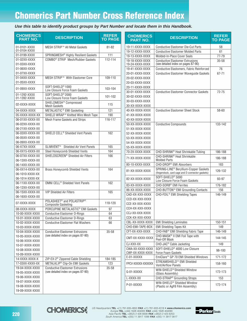
220US Headquarters TEL +(1) 781-935-4850 FAX +(1) 781-933-4318 • www.chomerics.com
Europe TEL +(44) 1628 404000 FAX +(44) 1628 404090Asia Pacific TEL +(852) 2 428 8008 FAX +(852) 2 423 8253
South America TEL +(55) 11 3917 1099 FAX +(55) 11 3917 0817
19-11-XXXX-XXXX Conductive Elastomer Die-Cut Parts 5819-12-XXXX-XXXX Conductive Elastomer Molded Parts 6119-13-XXXX-XXXX Molded-In-Place Cover Seals 77-7919-18-XXXX-XXXX Conductive Elastomer Extrusions 35-5819-24-XXXX-XXXX (see detailed index on pages 87-90)
19-41-XXXX-XXXX Conductive Elastomers, Fabric Reinforced 7620-01-XXXX-XXXX Conductive Elastomer Waveguide Gaskets 67-7120-02-XXXX-XXXX20-03-XXXX-XXXX20-11-XXXX-XXXX30-01-XXXX-XXXX Conductive Elastomer Connector Gaskets 72-7530-02-XXXX-XXXX30-03-XXXX-XXXX30-XX-XXXX-XXXX40-XX-XXXX-XXXX Conductive Elastomer Sheet Stock 58-6041-XX-XXXX-XXXX43-XX-XXXX-XXXX50-XX-XXXX-XXXX Conductive Compounds 133-14251-XX-XXXX-XXXX52-XX-XXXX-XXXX53-XX-XXXX-XXXX54-XX-XXXX-XXXX55-XX-XXXX-XXXX70-2X-XXXX-XXXX CHO-SHRINK® Heat Shrinkable Tubing 186-188
71-XX-XXXX-XXXX CHO-SHRINK® Heat Shrinkable 186-188Molded Parts80-10-XXXX-XXXX CHO-DROP® EMI Absorbers 183
81-XX-XXXX-XXXX SPRING-LINE® Beryllium-Copper Gaskets 126-132(fingerstock, card cage and D connector gaskets)
82-XX-XXXX-XXXX SOFT-SHIELD® 5000 93-97Low Closure Force Foam Gaskets83-XX-XXXX-XXXX CHO-SORB® EMI Ferrites 176-18286-XX-XXXX-XXXX CHO-BUTTONTM EMI Grounding Contacts 156CAD-XX-XXX-XXXX CHO-FOIL® EMI Shielding Tapes 146-149CCD-XX-XXX-XXXXCCE-XX-XXX-XXXXCCH-XX-XXX-XXXXCCJ-XX-XXX-XXXXCCK-XX-XXX-XXXXCBL-XX-XXXX-XXXX EMI Shielding Laminates 150-151CHO-EMI-TAPE-BOX EMI Shielding Tapes Kit 149CFT-XX-XXX-XXXX CHO-FABTM EMI Shielding Fabric Tape 146-149
CMT-XX-XXXX-XXXX CHO-MASK® II EMI Foil Tape with 144-145Peel-Off MaskCJ-XXX-XX CHO-JAC® Cable Jacketing 149CWA-XX-XXXX-XXXX SOFT-SHIELD® 4000 Low Closure 98-100CWF-XX-XXXX-XXXX Force Foam GasketsE-01-XXXXX EmiClareTM GP 70 EMI Shielded Windows 171-172
FPCV-XXXXX-XXXXXX STREAMSHIELDTM EMI Shielded 158-160Vent/Airflow Panels
G-01-XXXXX WIN-SHIELDTM Shielded Window 172-173(Glass Assembly)L-XXXX-XX CHO-STRAP® Grounding Straps 153
P-01-XXXXX WIN-SHIELDTM Shielded Window 172-174(Plastic or AgF8 Film Assembly)
Use this table to identify product groups by Part Number and locate them in this Handbook.
Chomerics Part Number Cross Reference Index
CHOMERICSPART NO.
DESCRIPTION REFERTO PAGE
CHOMERICS DESCRIPTION REFERPART NO. TO PAGE
01-0101-XXXX MESH STRIP TM All Metal Gaskets 81-8201-0104-XXXX01-0199-XXXX SPRINGMESH® Highly Resilient Gaskets 11101-02XX-XXXX COMBO® STRIP Mesh/Rubber Gaskets 112-11401-03XX-XXXX01-06XX-XXXX01-07XX-XXXX01-04XX-XXXX MESH STRIP TM With Elastomer Core 109-11001-05XX-XXXX
01-09XX-XXXX SOFT-SHIELD® 1000 103-104Low Closure Force Foam Gaskets01-1292-XXXX SOFT-SHIELD® 2000 101-10201-1392-XXXX Low Closure Force Foam Gaskets
02-XXXX-XXXX SHIELDMESHTM Compressed 115Mesh Gaskets04-XXXX-XXXX METALASTIC ® EMI Gasketing 12105-XXXX-XXXX-XX SHIELD WRAPTM Knitted Wire Mesh Tape 19006-01XX-XXXX-XX Mesh Frame Gaskets and Strips 116-11706-02XX-XXXX-XX06-21XX-XXXX-XX06-03XX-XXXX-XX SHIELD CELL® Shielded Vent Panels 16206-05XX-XXXX-XX06-09XX-XXXX-XX06-X7XX-XXXX SLIMVENTTM Shielded Air Vent Panels 16506-XX15-XXXX-XX Steel Honeycomb Shielded Vents 16406-07XX-XXXX-XX SHIELDSCREEN® Shielded Air Filters 16606-13XX-XXXX-XX06-14XX-XXXX-XX06-XX14-XXXX-XX Brass Honeycomb Shielded Vents 16406-1010-XXXX-XX06-1014-XXXX-XX06-11XX-XXXX-XX OMNI CELL® Shielded Vent Panels 16206-12XX-XXXX-XX06-15XX-XXXX-XX VIP Shielded Air Filters 16506-16XX-XXXX-XX
07-XXXX-XXXX POLASHEET® and POLASTRIP®
118-120Composite Gasketing08-XXXX-XXXX PORCUPINE METALASTIC® EMI Gaskets 9710-00-XXXX-XXXX Conductive Elastomer O-Rings 6410-01-XXXX-XXXX Conductive Elastomer D-Rings 6310-02-XXXX-XXXX Conductive Elastomer Flat Washers 6610-03-XXXX-XXXX10-04-XXXX-XXXX Conductive Elastomer Extrusions 35-5810-05-XXXX-XXXX (see detailed index on pages 87-90)
10-06-XXXX-XXXX10-07-XXXX-XXXX10-08-XXXX-XXXX10-09-XXXX-XXXX14-XXXX-XXXX-X ZIP-EX-2® Zippered Cable Shielding 184-18517-03XX-XXXX-XX METALKLIP® Clip-On EMI Gaskets 12319-04-XXXX-XXXX Conductive Elastomer Extrusions 35-5819-05-XXXX-XXXX (see detailed index on pages 87-90)
19-06-XXXX-XXXX19-07-XXXX-XXXX19-08-XXXX-XXXX19-09-XXXX-XXXX
221
Global Compliance Testing Page 222
Thermal ManagementProducts Page 224
US Headquarters TEL +(1) 781-935-4850 FAX +(1) 781-933-4318 • www.chomerics.comEurope TEL +(44) 1628 404000 FAX +(44) 1628 404090
Asia Pacific TEL +(852) 2 428 8008 FAX +(852) 2 423 8253South America TEL +(55) 11 3917 1099 FAX +(55) 11 3917 0817
Worldwide Sales Offices,Distributors & FabricatorsPage 226

222US Headquarters TEL +(1) 781-935-4850 FAX +(1) 781-933-4318 • www.chomerics.com
Europe TEL +(44) 1628 404000 FAX +(44) 1628 404090Asia Pacific TEL +(852) 2 428 8008 FAX +(852) 2 423 8253
South America TEL +(55) 11 3917 1099 FAX +(55) 11 3917 0817
ENGINEERING SUPPORT
Global Compliance Testing
Design ServicesForemost in our commitment to findingand solving EMI and safety designproblems is providing expert designassistance. After evaluating your prod-uct, we will identify trouble areas andsuggest practical solutions. With yourdesign criteria in mind, our engineerswill look across the full range of EMIand safety possibilities, including:
• EMI/EMC Packaging Design
• EMI/EMC Board-Level Design
• Safety Construction Review
• EMC/Safety Components Advice
• Prototype Fabrication Assistance
Full-Range Test CapabilitiesChomerics’ three shielded enclosuresfor commercial and military equipmenttesting include two measuring22x10x10 feet and one measuring20x16x10 feet. They include three adja-cent 8x8x8 foot shielded rooms for testand EUT support equipment. The20x16x10 room is a semi-anechoicfacility with absorber cones. One of the22x10x10-foot test chambers is a fully-anechoic, ferrite-lined enclosure thatmeets the field uniformity requirementsof EN 61000-4-3.
For commercial equipment emis-sions testing, Chomerics operates
Comprehensive EMI/EMC/Safety Compliance and Design ServicesChomerics, world leader in the manufacture of EMI shielding materials, offers full service compliance testing to meetemissions, immunity, susceptibility and safety requirements for commercial, military and government electronics.
What sets us apart from other test services are 35 years of experience in the EMI shielding industry, our EMI andsafety design capabilities, and the in-house availability of our entire line of shielding materials.
temperature-controlled 3- and 10-meteropen field test sites, both of whichexhibit characteristics accepted and onfile with the FCC. One site is equippedwith a flush mounted, 14-foot diameter,5000 lb. capacity turntable. Both sitesare equipped for 50 Hz/60 Hz power.
Frequency range of measurement for both emissions and susceptibility isDC to 100 GHz. Radiated susceptibilitytest equipment allows for field leveltesting to 200 volts/meter up to 40 GHz.A separate 16x12x10-foot shieldedenclosure is set up specifically forshielding effectiveness testing oncables, cabinets, shielded windows,shielded air vents, EMI gaskets andcomposite panels. In addition, transferimpedance measurement capabilities(30 MHz to 1 GHz) are available for planar materials per ASTM D4935 andEMI gaskets per SAE 1705.
For safety testing, our state-of-the-artlaboratory includes a temperature/humid-ity chamber, computer-controlled equip-ment to perform leakage testing, and aground controlled, programmable powersource. These enable us to evaluate yourproduct to all power line voltages and frequencies.
Safety Testing — UL, CSA andEuropean StandardsChomerics has extensive safety testingexperience in evaluating products anddetermining conformance with globalrequirements.
Products are evaluated for compli-ance with US Low Voltage, MedicalDevice and Machinery directives.Services include product evaluations tosafety standards, and assembly orevaluation of technical files when mak-ing a CE Self-Declaration. We can pro-vide verification reports outlining con-formance to product specific standards, third party review, and certification programs including notifiedbody review.
“Q” Test ProgramThe Q Test Program is for customerswho can ship their equipment to ourlaboratory, but are not present for thetest. Every Q Test customer receives acompletion date based on availability,schedules and deadlines, with a typicalturnaround of 10 days to two weeks.This allows us the flexibility to placeyour equipment into the queue for testing within the specified period.
Military and Avionics EquipmentQualificationChomerics is unrivaled in testing toMIL-STD and DO-160 specifications for electromagnetic susceptibility andemissions. Because we work withthese specifications on a daily basis,we know them inside and out. Ourexpert team of test technicians, appli-cations engineers, scientists andEMI/EMC engineers not only test yoursystem to military specifications, butalso integrate the proper qualifiedmaterials if EMI problems are encountered.
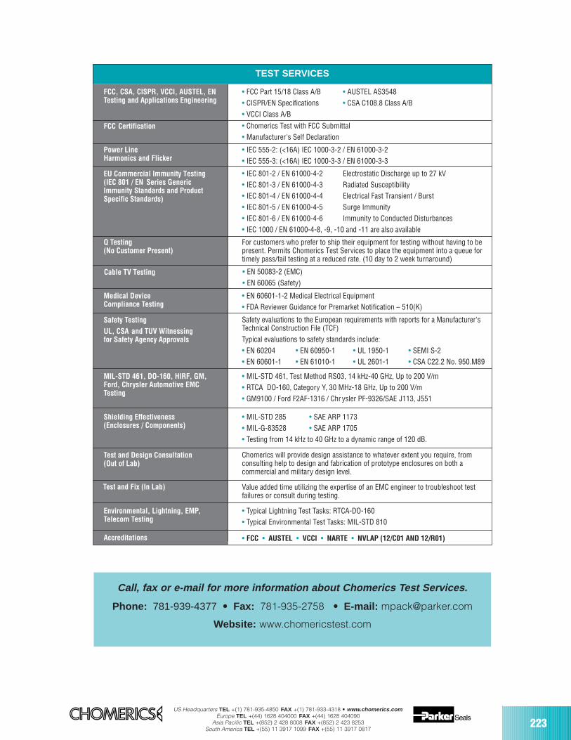
US Headquarters TEL +(1) 781-935-4850 FAX +(1) 781-933-4318 • www.chomerics.comEurope TEL +(44) 1628 404000 FAX +(44) 1628 404090
Asia Pacific TEL +(852) 2 428 8008 FAX +(852) 2 423 8253South America TEL +(55) 11 3917 1099 FAX +(55) 11 3917 0817
223
Call, fax or e-mail for more information about Chomerics Test Services.
Phone: 781-939-4377 • Fax: 781-935-2758 • E-mail: [email protected]
Website: www.chomericstest.com
FCC, CSA, CISPR, VCCI, AUSTEL, ENTesting and Applications Engineering
FCC Certification
• FCC Part 15/18 Class A/B • AUSTEL AS3548• CISPR/EN Specifications • CSA C108.8 Class A/B• VCCI Class A/B
• Chomerics Test with FCC Submittal• Manufacturer's Self Declaration
Power LineHarmonics and Flicker
• IEC 555-2: (<16A) IEC 1000-3-2 / EN 61000-3-2• IEC 555-3: (<16A) IEC 1000-3-3 / EN 61000-3-3
EU Commercial Immunity Testing(IEC 801 / EN Series GenericImmunity Standards and ProductSpecific Standards)
• IEC 801-2 / EN 61000-4-2 Electrostatic Discharge up to 27 kV• IEC 801-3 / EN 61000-4-3 Radiated Susceptibility• IEC 801-4 / EN 61000-4-4 Electrical Fast Transient / Burst• IEC 801-5 / EN 61000-4-5 Surge Immunity• IEC 801-6 / EN 61000-4-6 Immunity to Conducted Disturbances• IEC 1000 / EN 61000-4-8, -9, -10 and -11 are also available
Q Testing(No Customer Present)
For customers who prefer to ship their equipment for testing without having to bepresent. Permits Chomerics Test Services to place the equipment into a queue fortimely pass/fail testing at a reduced rate. (10 day to 2 week turnaround)
Medical DeviceCompliance Testing
• EN 60601-1-2 Medical Electrical Equipment• FDA Reviewer Guidance for Premarket Notification – 510(K)
Safety Testing
UL, CSA and TUV Witnessingfor Safety Agency Approvals
Safety evaluations to the European requirements with reports for a Manufacturer'sTechnical Construction File (TCF)Typical evaluations to safety standards include:• EN 60204 • EN 60950-1 • UL 1950-1 • SEMI S-2• EN 60601-1 • EN 61010-1 • UL 2601-1 • CSA C22.2 No. 950.M89
MIL-STD 461, DO-160, HIRF, GM,Ford, Chrysler Automotive EMCTesting
• MIL-STD 461, Test Method RS03, 14 kHz-40 GHz, Up to 200 V/m• RTCA DO-160, Category Y, 30 MHz-18 GHz, Up to 200 V/m• GM9100 / Ford F2AF-1316 / Chr ysler PF-9326/SAE J113, J551
Shielding Effectiveness(Enclosures / Components)
• MIL-STD 285 • SAE ARP 1173• MIL-G-83528 • SAE ARP 1705• Testing from 14 kHz to 40 GHz to a dynamic range of 120 dB.
Test and Design Consultation(Out of Lab)
Chomerics will provide design assistance to whatever extent you require, fromconsulting help to design and fabrication of prototype enclosures on both a commercial and military design level.
Test and Fix (In Lab) Value added time utilizing the expertise of an EMC engineer to troubleshoot testfailures or consult during testing.
Environmental, Lightning, EMP,Telecom Testing
• Typical Lightning Test Tasks: RTCA-DO-160• Typical Environmental Test Tasks: MIL-STD 810
Accreditations • FCC • AUSTEL • VCCI • NARTE • NVLAP (12/C01 AND 12/R01)
TEST SERVICES
Cable TV Testing • EN 50083-2 (EMC)• EN 60065 (Safety)
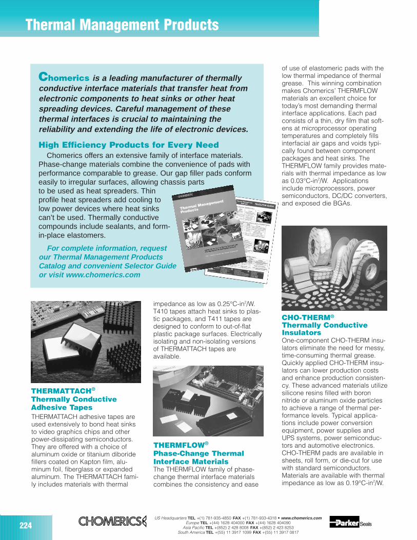
224US Headquarters TEL +(1) 781-935-4850 FAX +(1) 781-933-4318 • www.chomerics.com
Europe TEL +(44) 1628 404000 FAX +(44) 1628 404090Asia Pacific TEL +(852) 2 428 8008 FAX +(852) 2 423 8253
South America TEL +(55) 11 3917 1099 FAX +(55) 11 3917 0817
Thermal Management Products
Chomerics is a leading manufacturer of thermallyconductive interface materials that transfer heat fromelectronic components to heat sinks or other heatspreading devices. Careful management of these thermal interfaces is crucial to maintaining the reliability and extending the life of electronic devices.
High Efficiency Products for Every NeedChomerics offers an extensive family of interface materials.
Phase-change materials combine the convenience of pads withperformance comparable to grease. Our gap filler pads conformeasily to irregular surfaces, allowing chassis partsto be used as heat spreaders. Thinprofile heat spreaders add cooling tolow power devices where heat sinkscan’t be used. Thermally conductivecompounds include sealants, and form-in-place elastomers.
For complete information, requestour Thermal Management ProductsCatalog and convenient Selector Guideor visit www.chomerics.com
THERMFLOW®
Phase-Change ThermalInterface MaterialsThe THERMFLOW family of phase-change thermal interface materialscombines the consistency and ease
THERMATTACH®
Thermally ConductiveAdhesive TapesTHERMATTACH adhesive tapes areused extensively to bond heat sinksto video graphics chips and otherpower-dissipating semiconductors. They are offered with a choice of aluminum oxide or titanium diboridefillers coated on Kapton film, alu-minum foil, fiberglass or expandedaluminum. The THERMATTACH fami-ly includes materials with thermal
CHO-THERM®
Thermally ConductiveInsulatorsOne-component CHO-THERM insu-lators eliminate the need for messy,time-consuming thermal grease.Quickly applied CHO-THERM insu-lators can lower production costsand enhance production consisten-cy. These advanced materials utilizesilicone resins filled with boronnitride or aluminum oxide particlesto achieve a range of thermal per-formance levels. Typical applica-tions include power conversionequipment, power supplies andUPS systems, power semiconduc-tors and automotive electronics.CHO-THERM pads are available insheets, roll form, or die-cut for usewith standard semiconductors.Materials are available with thermalimpedance as low as 0.19°C-in2/W.
impedance as low as 0.25°C-in2/W.T410 tapes attach heat sinks to plas-tic packages, and T411 tapes aredesigned to conform to out-of-flatplastic package surfaces. Electricallyisolating and non-isolating versionsof THERMATTACH tapes are available.
of use of elastomeric pads with thelow thermal impedance of thermalgrease. This winning combinationmakes Chomerics’ THERMFLOWmaterials an excellent choice fortoday’s most demanding thermalinterface applications. Each padconsists of a thin, dry film that soft-ens at microprocessor operatingtemperatures and completely fillsinterfacial air gaps and voids typi-cally found between componentpackages and heat sinks. TheTHERMFLOW family provides mate-rials with thermal impedance as lowas 0.03°C-in2/W. Applicationsinclude microprocessors, powersemiconductors, DC/DC converters,and exposed die BGAs.
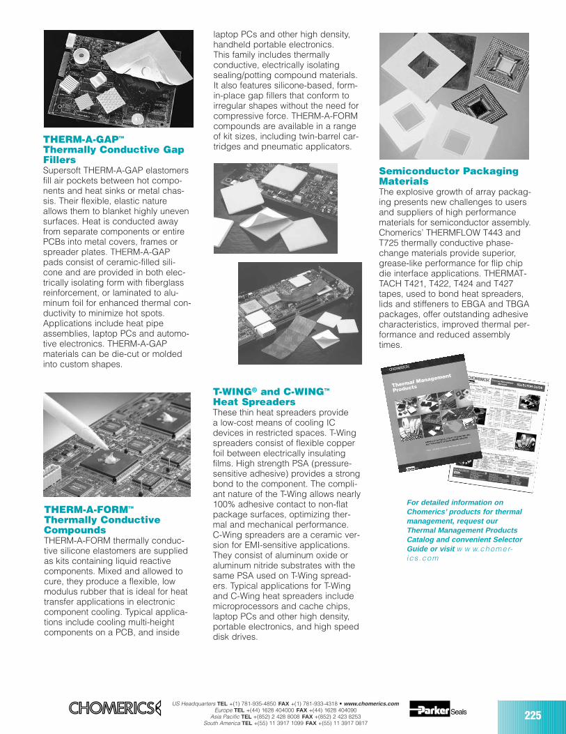
US Headquarters TEL +(1) 781-935-4850 FAX +(1) 781-933-4318 • www.chomerics.comEurope TEL +(44) 1628 404000 FAX +(44) 1628 404090
Asia Pacific TEL +(852) 2 428 8008 FAX +(852) 2 423 8253South America TEL +(55) 11 3917 1099 FAX +(55) 11 3917 0817
225
THERM-A-GAPTM
Thermally Conductive GapFillersSupersoft THERM-A-GAP elastomersfill air pockets between hot compo-nents and heat sinks or metal chas-sis. Their flexible, elastic natureallows them to blanket highly unevensurfaces. Heat is conducted awayfrom separate components or entirePCBs into metal covers, frames orspreader plates. THERM-A-GAPpads consist of ceramic-filled sili-cone and are provided in both elec-trically isolating form with fiberglassreinforcement, or laminated to alu-minum foil for enhanced thermal con-ductivity to minimize hot spots.Applications include heat pipeassemblies, laptop PCs and automo-tive electronics. THERM-A-GAPmaterials can be die-cut or moldedinto custom shapes.
Semiconductor PackagingMaterialsThe explosive growth of array packag-ing presents new challenges to usersand suppliers of high performancematerials for semiconductor assembly.Chomerics’ THERMFLOW T443 andT725 thermally conductive phase-change materials provide superior,grease-like performance for flip chipdie interface applications. THERMAT-TACH T421, T422, T424 and T427tapes, used to bond heat spreaders,lids and stiffeners to EBGA and TBGApackages, offer outstanding adhesivecharacteristics, improved thermal per-formance and reduced assemblytimes.
T-WING® and C-WINGTM
Heat SpreadersThese thin heat spreaders provide a low-cost means of cooling ICdevices in restricted spaces. T-Wingspreaders consist of flexible copperfoil between electrically insulatingfilms. High strength PSA (pressure-sensitive adhesive) provides a strongbond to the component. The compli-ant nature of the T-Wing allows nearly100% adhesive contact to non-flatpackage surfaces, optimizing ther-mal and mechanical performance. C-Wing spreaders are a ceramic ver-sion for EMI-sensitive applications.They consist of aluminum oxide oraluminum nitride substrates with thesame PSA used on T-Wing spread-ers. Typical applications for T-Wingand C-Wing heat spreaders includemicroprocessors and cache chips,laptop PCs and other high density,portable electronics, and high speeddisk drives.
THERM-A-FORMTM
Thermally ConductiveCompoundsTHERM-A-FORM thermally conduc-tive silicone elastomers are suppliedas kits containing liquid reactivecomponents. Mixed and allowed tocure, they produce a flexible, lowmodulus rubber that is ideal for heattransfer applications in electroniccomponent cooling. Typical applica-tions include cooling multi-heightcomponents on a PCB, and inside
For detailed information onChomerics’ products for thermalmanagement, request ourThermal Management ProductsCatalog and convenient SelectorGuide or visit w w w.chomer-ics .com
laptop PCs and other high density,handheld portable electronics. This family includes thermally conductive, electrically isolatingsealing/potting compound materials.It also features silicone-based, form-in-place gap fillers that conform toirregular shapes without the need forcompressive force. THERM-A-FORMcompounds are available in a rangeof kit sizes, including twin-barrel car-tridges and pneumatic applicators.