jwus elwpwm c01 1. -...
TRANSCRIPT
PART I
IEEE 802.11 WIRELESS LANs
COPYRIG
HTED M
ATERIAL


CHAPTER 1
IEEE 802.11 MEDIUM ACCESSCONTROL AND PHYSICAL LAYERS
KAVEH GHABOOSI, MATTI LATVA-AHO, and YANG XIAO
1.1 INTRODUCTION
A wireless local area network (WLAN) is an information system1 intended tooffer diverse location-independent network service access to portable wirelessdevices using radio waves instead of wired infrastructure. In corporateenterprises, WLANs are typically deployed as the ultimate connection betweenan existing cable infrastructure network and a cluster of mobile clients, givingthem wireless access to the shared resources of the corporate network across abuilding or campus setting. Fundamentally, WLANs liberate customers fromreliance on hard-wired access to the network backbone, giving them anywhere,anytime network services access. The pervasive approval of WLANs dependsupon industry standardization to ensure product compatibility and reliabilityamong various brands and manufacturers. Among existing system architec-tures, the IEEE 802.11 family is the most popular and accepted standardconcerning medium access control (MAC) and physical (PHY) layers inWLANs; therefore, in this chapter, we briefly overview its basic features inboth aforementioned layers. We start our investigation with the MAC layerand its fundamental components. Supported network types, different networkservices, and media access schemes are covered, accordingly. Subsequently, thephysical layer and its basic characteristics are discussed. Different technologies,
Emerging Wireless LANs, Wireless PANs, and Wireless MANs. Edited by Y. Xiao and Y. PanCopyright r 2009 John Wiley & Sons, Inc.
1 In telecommunications, an information system is any telecommunications and/or computer-
related equipment or interconnected system or subsystems of equipment that are used in the
acquisition, storage, manipulation, management, movement, control, display, switching, inter-
change, transmission, or reception of voice and/or data and includes software, firmware, and
hardware (Federal Standard 1037C, MIL-STD-188, and National Information Systems Security
Glossary).
3

including frequency hopping (FH), direct-sequence spread spectrum (DSSS)and its high rate (HR) counterpart (i.e., HR/DSSS), and orthogonal frequencydivision multiplexing (OFDM), recommended for the IEEE 802.11 physicallayer are then explored. As a result, this chapter can be assumed as acomprehensive overview of the IEEE 802.11 standard.
1.2 IEEE 802.11 MAC PROTOCOL
In 1997, the IEEE 802.11 working group (WG) proposed the IEEE802.11 WLAN standard and, subsequently, a revised version was releasedin 1999. The primary medium access scheme in IEEE 802.11 MAC is thedistributed coordination function (DCF), a contention-based protocol whichis based on the carrier sense multiple-access/collision avoidance (CSMA/CA)protocol. In the DCF, mobile terminals should contend for the sharedwireless channel, and as a result, the medium access delay for each station(STA) cannot be bounded in heavy-traffic-load circumstances. Thus, theDCF is capable of offering only asynchronous data transmission on a besteffort (BE) basis. In order to support real-time traffic such as voice and video,the point coordination function (PCF) scheme has been advised as anoncompulsory option. Basically, the PCF is based on a centralized pollingscheme for which a point coordinator (PC) residing in an access point (AP)provides contention-free services to the associated stations in a polling list. Inaddition to the IEEE 802.11 standard [1], there is a well-known book by Gast[2] which is considered as a complete scientific review of 802.11 families. Dueto the popularity of the aforementioned book, we will use it frequentlythroughout the section to refer the reader to more technical issues anddiscussions.
Recently, considerable interest in wireless networks supporting quality ofservice (QoS) has grown noticeably. The PCF is already available in IEEE802.11 to offer QoS but has not yet been implemented in reality due to itsnumerous technical limitations and performance drawbacks. For that reason,the 802.11 WG initiated IEEE 802.11e activity to develop the existing 802.11MAC to facilitate support of QoS. Regarding the 802.11e amendment, not onlythe IEEE 802.11e standard [3] but also recognized introductory and surveypapers [4, 5] will be used repeatedly as key references. We cite many technicalissues from these works and the references therein to more appropriatelyexplain 802.11/802.11e-based system features.
1.2.1 Categories of 802.11 Networks
The key constructing component of an 802.11 network is the basic service set(BSS), a group of wireless terminals that communicate with each other over acommon radio channel [1, 2]. Data transmission is accomplished within a basic
4 IEEE 802.11 MEDIUM ACCESS CONTROL AND PHYSICAL LAYERS

service area, defined by radio propagation characteristics of wireless channel.BSSs come in two categories, as illustrated in Fig. 1.1.
The infrastructure BSS networks are primary for mobile stations to accessthe Internet via an AP so that, in most of cases, communications between twostations within the same service set do not happen. In communications betweenmobile stations in the same service set, the AP deployment acts as anintermediate node for all information exchanges comprising communications.In other words, any data communication between two wireless clients shouldtake two successive hops, i.e., source STA to AP and AP to destination STA.Obviously, the exploitation of APs in infrastructure networks brings two majoradvantages. On the one hand, no restriction is placed on the physical distancebetween mobile stations. On the other hand, allowing straight communicationbetween wireless terminals would apparently preserve system capacity2 but atthe cost of increased physical and MAC layer complexity. The most importantfunctions of an AP are to assist stations in accessing the Internet and help savebattery power in associated wireless stations. If a mobile terminal is in thepower-saving (PS) mode, the AP buffers those frames destined to reach thestation during the period it will be in PS status. When the terminal exits the PSmode, the AP forwards the cached data frames to the station one by one.Hence, APs evidently play a key role in infrastructure networks to makeimplementation of PS mechanisms possible [1].
In the independent BSS (IBSS), mobile stations are allowed to communicatedirectly. Characteristically, IBSSs are composed of a few stations configured
Infrastructure basic service setaccess point
Independent basic service set (IBSS)
PDA
PDAPDA
Tablet PCTablet PC
Laptop
Laptop
FIGURE 1.1 Infrastructure and independent basic service sets.
2 In computer science, channel capacity is the amount of discrete information that can be reliably
transmitted over a channel. By the noisy-channel coding theorem, the channel capacity of a given
channel is the limiting information transport rate (in units of information per unit time) that can be
achieved with vanishingly small error probability.
1.2 IEEE 802.11 MAC PROTOCOL 5
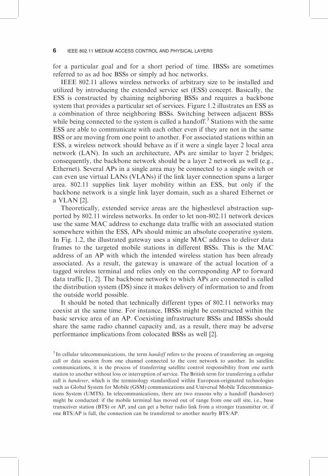
for a particular goal and for a short period of time. IBSSs are sometimesreferred to as ad hoc BSSs or simply ad hoc networks.
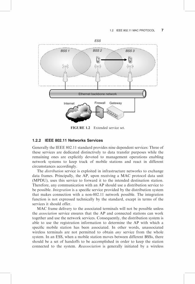
IEEE 802.11 allows wireless networks of arbitrary size to be installed andutilized by introducing the extended service set (ESS) concept. Basically, theESS is constructed by chaining neighboring BSSs and requires a backbonesystem that provides a particular set of services. Figure 1.2 illustrates an ESS asa combination of three neighboring BSSs. Switching between adjacent BSSswhile being connected to the system is called a handoff.3 Stations with the sameESS are able to communicate with each other even if they are not in the sameBSS or are moving from one point to another. For associated stations within anESS, a wireless network should behave as if it were a single layer 2 local areanetwork (LAN). In such an architecture, APs are similar to layer 2 bridges;consequently, the backbone network should be a layer 2 network as well (e.g.,Ethernet). Several APs in a single area may be connected to a single switch orcan even use virtual LANs (VLANs) if the link layer connection spans a largerarea. 802.11 supplies link layer mobility within an ESS, but only if thebackbone network is a single link layer domain, such as a shared Ethernet ora VLAN [2].
Theoretically, extended service areas are the highestlevel abstraction sup-ported by 802.11 wireless networks. In order to let non-802.11 network devicesuse the same MAC address to exchange data traffic with an associated stationsomewhere within the ESS, APs should mimic an absolute cooperative system.In Fig. 1.2, the illustrated gateway uses a single MAC address to deliver dataframes to the targeted mobile stations in different BSSs. This is the MACaddress of an AP with which the intended wireless station has been alreadyassociated. As a result, the gateway is unaware of the actual location of atagged wireless terminal and relies only on the corresponding AP to forwarddata traffic [1, 2]. The backbone network to which APs are connected is calledthe distribution system (DS) since it makes delivery of information to and fromthe outside world possible.
It should be noted that technically different types of 802.11 networks maycoexist at the same time. For instance, IBSSs might be constructed within thebasic service area of an AP. Coexisting infrastructure BSSs and IBSSs shouldshare the same radio channel capacity and, as a result, there may be adverseperformance implications from colocated BSSs as well [2].
3 In cellular telecommunications, the term handoff refers to the process of transferring an ongoing
call or data session from one channel connected to the core network to another. In satellite
communications, it is the process of transferring satellite control responsibility from one earth
station to another without loss or interruption of service. The British term for transferring a cellular
call is handover, which is the terminology standardized within European-originated technologies
such as Global System for Mobile (GSM) communications and Universal Mobile Telecommunica-
tions System (UMTS). In telecommunications, there are two reasons why a handoff (handover)
might be conducted: if the mobile terminal has moved out of range from one cell site, i.e., base
transceiver station (BTS) or AP, and can get a better radio link from a stronger transmitter or, if
one BTS/AP is full, the connection can be transferred to another nearby BTS/AP.
6 IEEE 802.11 MEDIUM ACCESS CONTROL AND PHYSICAL LAYERS
1.2.2 IEEE 802.11 Networks Services
Generally the IEEE 802.11 standard provides nine dependent services: Three ofthese services are dedicated distinctively to data transfer purposes while theremaining ones are explicitly devoted to management operations enablingnetwork systems to keep track of mobile stations and react in differentcircumstances accordingly.
The distribution service is exploited in infrastructure networks to exchangedata frames. Principally, the AP, upon receiving a MAC protocol data unit(MPDU), uses this service to forward it to the intended destination station.Therefore, any communication with an AP should use a distribution service tobe possible. Integration is a specific service provided by the distribution systemthat makes connection with a non-802.11 network possible. The integrationfunction is not expressed technically by the standard, except in terms of theservices it should offer.
MAC frame delivery to the associated terminals will not be possible unlessthe association service ensures that the AP and connected stations can worktogether and use the network services. Consequently, the distribution system isable to use the registration information to determine the AP with which aspecific mobile station has been associated. In other words, unassociatedwireless terminals are not permitted to obtain any service from the wholesystem. In an ESS, when a mobile station moves between different BSSs, thereshould be a set of handoffs to be accomplished in order to keep the stationconnected to the system. Reassociation is generally initiated by a wireless
ESS
BSS 1 BSS 2 BSS 3
Ethernet backbone network
FirewallInternet Gateway
FIGURE 1.2 Extended service set.
1.2 IEEE 802.11 MAC PROTOCOL 7

terminal once the signal strength indicates that a different association isnecessary. This means that handoff and reassociation requests are nevercommenced by APs. Upon completion of reassociation, the distribution systemrenews its location records to reflect the latest information about reachability ofthe mobile station. To terminate an existing association, wireless stations maypossibly use the so-called disassociation service. Upon invocation of disassocia-tion, any mobility information stored in the distribution system correspondingto the requesting station is removed at once.
Authentication is an obligatory prerequisite to association due to the factthat only authenticated users are authorized to use the network resources. If theAPs of a distribution system have been configured in such a way as toauthenticate any station, then the system is called an ‘‘open system’’ or an‘‘open network.’’ These kinds of wireless networks can be found, for instance,at university campuses. Deauthentication terminates an authenticated relation-ship between an AP and a wireless station. Since authentication is requiredbefore system resources utilization, a side effect of deauthentication is termina-tion of any existing association.
IEEE 802.11 offers a noncompulsory privacy service called wired equivalentprivacy (WEP). WEP is not iron-clad security; in fact, it can be easily disabled.In response, the IEEE 802.11i task group (TG) is seeking an enhanced andstronger security scheme to be included in the next generation of 802.11equipments. IEEE 802.11i, known as WiFi-protected access version 2(WPA2), is an amendment to the 802.11 standard specifying security mechan-isms for wireless networks. It makes use of the advanced encryption standard(AES) block cipher, while WEP and WPA (an earlier version) use the RC4stream cipher. The 802.11i architecture contains the following components:802.1X for authentication [entailing the use of extensible authenticationprotocol (EAP) and an authentication server], the robust security network(RSN) for keeping track of associations, and the AES-based counter mode withcipher block-chaining message authentication code protocol (CCMP) toprovide confidentiality, integrity, and origin authentication. Another importantelement of the authentication process is an innovative four-way handshake.
The MPDU is a fancy name for 802.11 MAC frames. The MPDU does not,however, include PHY layer convergence procedure (PLCP) headers. On theother hand, the MAC service data units (MSDUs) are only composed of higherlevel data units [e.g., Internet protocol (IP) layer]. For instance, an 802.11management frame does not contain an MSDU. Wireless stations provide theMSDU delivery service, which is responsible for getting the data to the actualrecipient.
1.2.3 IEEE 802.11 Media Access Schemes
In what follows, we discuss the medium access rules defined in the 802.11standard and its corresponding amendments. We begin the discussion with thecontention-based 802.11 DCF access scheme. Subsequently, a few paragraphs
8 IEEE 802.11 MEDIUM ACCESS CONTROL AND PHYSICAL LAYERS

are dedicated to the 802.11 PCF, which is a contention-free channel acquisitiontechnique. Finally, the supplementary QoS-aware amendment of the IEEE802.11 standard, i.e., the 802.11e hybrid coordination function (HCF), isexplored [1–3].
1.2.3.1 IEEE 802.11 DCF. The fundamental IEEE 802.11 access scheme isreferred to as the DCF and operates based upon a listen-before-talk (LBT)approach and CSMA/CA.
As indicated, MSDUs are transmitted using MPDUs. If the wireless stationchooses to fragment a long MSDU into a number of MPDUs, then it shouldsend the long MSDU through more than one MPDU over the radio system.802.11 stations deliver MSDUs following a media detection procedure dealingwith an idle wireless channel that can be acquired for data transmission. If morethan one station senses the communication channel as being idle at the sametime, they might commence their frame transmissions simultaneously, andinevitably a collision occurs subsequently. To minimize the collision risk, theDCF uses carrier sense functions and a binary exponential backoff (BEB)mechanism. In particular, two carrier sense schemes, namely physical andvirtual carrier sense functions, are employed to simultaneously resolve the stateof the radio channel. The former is offered by the physical layer and the latterby the MAC layer, called network allocation vector (NAV). The NAV recordsthe duration that the medium will be busy based upon information announcedbefore the control/data frames are captured over the air interface. If eitherfunction indicates a busy medium, the medium is considered busy (i.e., reservedor occupied); if not, it is considered idle. Subsequent to detection of wirelessmedium as idle, for a so-called DCF interframe space (DIFS) time duration,stations continue sensing the channel for an extra random time period called abackoff period. The wireless station begins traffic delivery whenever the sharedmedium remains idle over this further random time interval. The backoff timeis determined by each station as a multiple of a pre defined slot time chosen in astochastic fashion. This means that a fresh independent random value isselected for every new transmission. In the BEB algorithm, each station choosesa random backoff timer uniformly distributed in an interval [0, CW – 1], whereCW is the current contention window size. It decreases the backoff timer by 1 forevery idle time slot. Transmission is started whenever the backoff timer reacheszero. When frame transmission fails due to any reason, the station doubles theCW until it reaches the maximum value CWmax. Afterward, the tagged stationrestarts the backoff procedure and retransmits the MAC frame when thebackoff counter reaches zero. If the maximum transmission retry limit isreached, the retransmission should be stopped, the CW should be reset to theinitial value CWmin, and the MAC frame is simply discarded. At the same timeas a wireless station is counting down its backoff counter, if the radio channelbecomes busy, it suspends its backoff counter decrement and defers from themedia acquisition until the medium again becomes idle for a DIFS [1, 2, 4, 5].
1.2 IEEE 802.11 MAC PROTOCOL 9

Each MPDU requires the reception of an acknowledgment (ACK) frame toconfirm its correct transmission over the wireless channel. If for any reason theintended ACK frame is not received right after the MPDU transmission, thesource station concludes that the MPDU was not delivered successfully and mayreiterate the transmission. Basically, the CW size of a contending stationincreases when the transmission fails. After an unsuccessful effort, the backoffprocedure is restarted with a double-sized CW, up to a maximum value definedby CWmax. Alternatively, subsequent to a successful transmission, the taggedstation exploits another random backoff, even if there is no further queuedMSDU to be delivered over the air interface. In the literature, this extra backoffis referred to as post-backoff given that it is executed subsequent to the dataframe departure. There is an exception to the above-mentioned rule: If anMSDU arrives from layer 3 when (1) the transmission queue is vacant, (2) thelatest post-backoff has finished, and (3) the medium has been idle for at least oneDIFS, then it may be delivered at once with no further backoff procedure [4].
To overcome the so-called hidden terminal problem, the IEEE 802.11 DCFmedia access scheme utilizes a request-to-send/clear-to-send (RTS/CTS) me-chanism which can be exploited optionally prior to MPDU transmission. Asillustrated in Figure 1.3, the source station sends an RTS control frame to itsintended destination. Upon reception of the RTS by the receiver, it sends a CTSframe back to the source station. The RTS and CTS frames include informa-tion on how long it will take to deliver the upcoming data frame (in thefragmentation case, it indicates the duration of the first fragment) and thecorresponding ACK over the radio link. Upon reception of either the RTS orCTS, wireless stations located in the radio range of the transmitting node, inaddition to those hidden to the source node and located in the transmissionrange of the destination station, set their local timer NAV, with the durationannounced within the RTS/CTS frames. The RTS and CTS frames protect theMPDU from interferences due to other neighboring wireless nodes. Stationsthat receive these control frames will not initiate transmission until the above-mentioned NAV timer expires. Between two consecutive frames in the sequence
SIFS
RTS
CTS
Source
Destination
NAV
DATA
NAV (RTS)
NAV (CTS)
DIFS
ACK
Slot time
Contentionwindow
Channelaccess with
backoff
FIGURE 1.3 IEEE 802.11 RTS/CTS access scheme.
10 IEEE 802.11 MEDIUM ACCESS CONTROL AND PHYSICAL LAYERS

of RTS, CTS, MPDU, and ACK frames, a short interframe space (SIFS) givestransceivers time to switch (i.e., between transmitting and receiving modes). Itis noteworthy that the SIFS is shorter than the DIFS, which gives the CTS andACK the highest priority access to the wireless medium [1].
1.2.3.2 IEEE 802.11 PCF. IEEE 802.11 employs an optional PCF tosupport QoS for time-bound delay-sensitive services. The PCF offers techni-ques for prioritized access to the shared radio channel and is centrallycoordinated by a PC station which is typically an AP. The PCF has higherpriority than the DCF scheme. With the PCF, a contention-free period (CFP)and a contention period (CP) alternate periodically over time, where a CFP andthe subsequent CP form an 802.11 superframe. The PCF is exploited through-out the CFP, while the DCF is used during the CP access phase. Eachsuperframe is required to comprise a CP of a minimum length that allows atleast one MSDU delivery (at least one frame exchange) of maximum size and atthe slowest transmission rate under the DCF. A superframe is initiated by abeacon frame generated by the AP. The beacon frame is transmitted irrespec-tive of whether or not the PCF is used. These frames are employed to preservesynchronization of the local timers in the associated stations and to deliverprotocol-related parameters. The AP transmits these management frames atregular predefined intervals. Each station knows precisely when the subsequentbeacon will arrive. These points in the time domain are referred to as targetbeacon transmission time (TBTT) and are announced in the previous beaconframe [1, 2].
During the CFP, there is no contention among wireless stations; instead,they are polled periodically by the AP. The PC polls a station requestingdelivery of a pending data frame. Whenever the PC has a pending framedestined to an intended station, it utilizes a joint data and poll frame bypiggybacking the CF-Poll frame onto the data frame. Upon reception of the so-called CF-Poll+Data, the polled station acknowledges the successful datareception and piggybacks an MPDU as well if it has any pending data frametargeted to the AP. If the PC does not receive a response from a polled stationafter waiting for a PCF interframe space (PIFS), it polls the next station or endsthe CFP. Thus, no idle period longer than a PIFS occurs during a CFP. Bear inmind that a PIFS is longer than a SIFS but shorter than a DIFS. Since a PIFS islonger than an SIFS, a poll is never issued, e.g., between Data and ACKframes; hence a poll frame does not interrupt an ongoing frame exchange. ThePC continues the aforementioned procedure until the CFP expires. A particularcontrol frame, CF-End, is broadcast by the AP as the last frame within a CFPto indicate the end of the CFP (see Fig. 1.4) [1, 2, 4].
The PCF has many problems that have been reported in the literature [4].Among many others, erratic beacon frame delay and indefinite transmissionduration of the polled stations are the most important drawbacks. At theTBTT, the PC schedules the beacon as the next frame to be transmitted, but thebeacon can only be transmitted when the medium has been determined to be
1.2 IEEE 802.11 MAC PROTOCOL 11

idle for at least one PIFS. In IEEE 802.11, wireless stations are able to starttheir channel access even if the MSDU delivery is not finished before theupcoming TBTT. Depending upon whether the shared medium is idle or busyat the TBTT, a delay of the beacon frame might take place. The time the beaconframe is delayed from the TBTT determines the delay in a time-boundedMSDU transmission that has to be delivered in the CFP. This may rigorouslyinfluence the QoS as it introduces unpredictable time delays in each CFP. Afurther problem with the PCF is the unknown transmission duration of polledstations. A station that has been polled by the PC is allowed to deliver anMSDU that may be fragmented and of arbitrary length. In addition, differentmodulation and coding schemes are specified in the IEEE 802.11 family.Therefore, the duration of the MSDU is not under the control of the PC,which degrades the QoS offered to other stations polled during the rest of theCFP.
1.2.3.3 IEEE 802.11e: QoS Support in IEEE 802.11 MAC. The HCF,introduced in IEEE 802.11e, consists of two fundamental components: en-hanced distributed-channel access (EDCA), an HCF contention-based channelaccess mechanism, and HCF controlled-channel access (HCCA). EDCA is theprimary and mandatory access mechanism of IEEE 802.11e, while HCCA isoptional and requires centralized polling and advanced scheduling schemes todistribute shared network resources among associated stations. According tothe IEEE 802.11e, there can be two separate phases of operation within asuperframe: CP and CFP. EDCA is used in the CP only, while HCCA is used inboth phases. The HCF combines access methods of both the PCF and DCF,and this is why it is called hybrid [3].
The wireless station that operates as the central coordinator within a QoS-supporting basic service set (QBSS) is called a hybrid coordinator (HC). Similarto the PC, the HC resides within an 802.11e AP (i.e., QoS enabled access point(QAP)). There are multiple backoff entities operating in parallel within oneQoS-aware 802.11e station (QSTA). A QSTA that is granted medium accessopportunity should not occupy the radio resources for a time duration longerthan a prespecified limit. This important characteristic of the 802.11e MACprotocol is referred to as transmission opportunity (TXOP). A TXOP is the
PIFS
CP Beacon DATA + CF-Poll
SIFS
DATA + CF-ACK
DATA + CF-Poll CF-End
CPCF-ACK
Access point
Station
NAV
TBTTContention-free period (CFP)
NAV (for DCF-based wireless stations)
FIGURE 1.4 IEEE 802.11 PCF access scheme and TBTT.
12 IEEE 802.11 MEDIUM ACCESS CONTROL AND PHYSICAL LAYERS
time interval during which a backoff entity has the right to deliver MSDUs andis defined by its starting time and duration. TXOPs obtained throughout thecontention-based phase are referred to as EDCA–TXOPs. Alternatively, aTXOP obtained via a controlled medium access scheme is called an HCCA–TXOP or polled TXOP. The duration of an EDCA–TXOP is limited by aQBSS-wide parameter referred to as the TXOPlimit. This parameter isdistributed regularly by the HC within an information field of the beaconframe. A further enhancement is that backoff entities of QSTAs are totallyforbidden from transmitting across the TBTT. That is, a frame transmission iscommenced only if it can be completed ahead of the upcoming TBTT. Thisreduces the expected beacon delay, which gives the HC superior control overthe wireless media, especially if the noncompulsory CFP is exploited after thebeacon frame. Moreover, an 802.11e backoff entity is allowed to exchangedata frames directly with another backoff entity in a QBSS without involvingcommunication with the QAP. Whereas within an 802.11-based infrastructureBSS all data frames are either sent or received by the AP, an 802.11e QSTA canestablish a direct link with another 802.11e QSTA using the direct-link protocol(DLP) prior to initiating direct frame transmissions. It should be noted thathere the backoff entity deals with the local backoff entity of a tagged QSTA;therefore, they are used interchangeably [3–5].
1.2.3.3.1 IEEE 802.11e: EDCA. In EDCA, QSTAs have up to four distinctand parallel queues for incoming traffic. Each queue is coupled with a specificaccess category (AC) and contends for the radio channel independent of theothers. Collisions among a tagged station’s queues are resolved internally,allowing the higher priority queue to commence its transmission while forcingthe lower priority queue(s) to perform a collision response.4 Different levels ofservice are provided to each AC through a combination of three servicedifferentiation mechanisms: arbitrary interframe space (AIFS), CW size, andTXOPlimit [3].
In contrast to the DCF access rules by which the backoff procedure isstarted after the DIFS from the end of the last indicated busy medium, EDCAbackoff entities start at different intervals according to the corresponding ACof the traffic queue. As already pointed out, these time intervals are calledAIFSs. The time duration of the interframe spaceAIFS[AC] is given by
AIFS½AC� ¼ SIFSþAIFSN½AC� � aSlotTime
where AIFSN[AC] Z 2. Note that AIFSN[AC] should be chosen by the HCsuch that the earliest access time of 802.11e stations to be the DIFS, equivalentto IEEE 802.11. Note that the parameter aSlotTime defines the duration of a
4 In the literature, the internal collision between independent backoff entities is called virtual
collision.
1.2 IEEE 802.11 MAC PROTOCOL 13
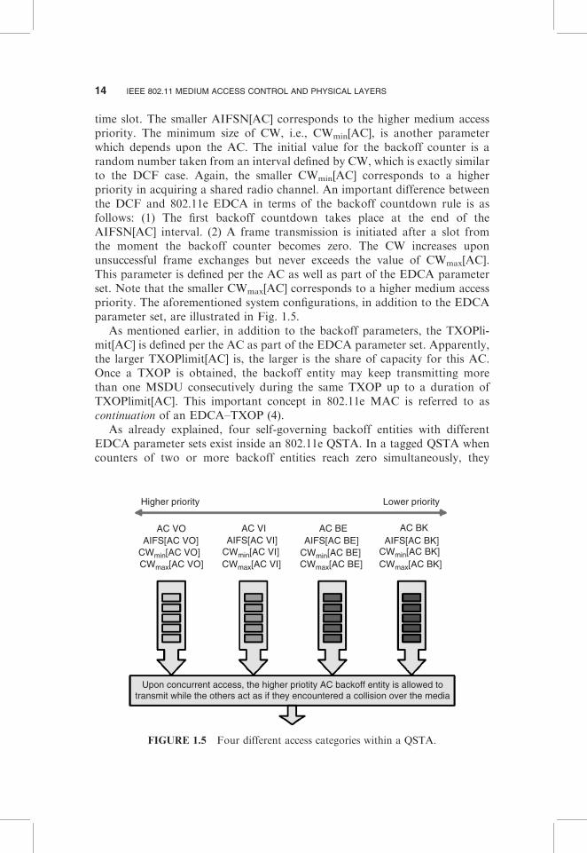
time slot. The smaller AIFSN[AC] corresponds to the higher medium accesspriority. The minimum size of CW, i.e., CWmin[AC], is another parameterwhich depends upon the AC. The initial value for the backoff counter is arandom number taken from an interval defined by CW, which is exactly similarto the DCF case. Again, the smaller CWmin[AC] corresponds to a higherpriority in acquiring a shared radio channel. An important difference betweenthe DCF and 802.11e EDCA in terms of the backoff countdown rule is asfollows: (1) The first backoff countdown takes place at the end of theAIFSN[AC] interval. (2) A frame transmission is initiated after a slot fromthe moment the backoff counter becomes zero. The CW increases uponunsuccessful frame exchanges but never exceeds the value of CWmax[AC].This parameter is defined per the AC as well as part of the EDCA parameterset. Note that the smaller CWmax[AC] corresponds to a higher medium accesspriority. The aforementioned system configurations, in addition to the EDCAparameter set, are illustrated in Fig. 1.5.
As mentioned earlier, in addition to the backoff parameters, the TXOPli-mit[AC] is defined per the AC as part of the EDCA parameter set. Apparently,the larger TXOPlimit[AC] is, the larger is the share of capacity for this AC.Once a TXOP is obtained, the backoff entity may keep transmitting morethan one MSDU consecutively during the same TXOP up to a duration ofTXOPlimit[AC]. This important concept in 802.11e MAC is referred to ascontinuation of an EDCA–TXOP (4).
As already explained, four self-governing backoff entities with differentEDCA parameter sets exist inside an 802.11e QSTA. In a tagged QSTA whencounters of two or more backoff entities reach zero simultaneously, they
Higher priority Lower priority
AC VO AC VI AC BE AC BKAIFS[AC VO]
CWmin[AC VO] CWmin[AC VI] CWmin[AC BE] CWmin[AC BK]CWmax[AC VI] CWmax[AC BE] CWmax[AC BK]CWmax[AC VO]
AIFS[AC VI] AIFS[AC BE] AIFS[AC BK]
Upon concurrent access, the higher priotity AC backoff entity is allowed totransmit while the others act as if they encountered a collision over the media
FIGURE 1.5 Four different access categories within a QSTA.
14 IEEE 802.11 MEDIUM ACCESS CONTROL AND PHYSICAL LAYERS

perform channel acquisition in the same time slot and consequently an internalvirtual collision occurs. It should be noted that virtual collision is an abstractconcept and there is no physical collision between contending backoff entities.When internal virtual collision occurs, the AC with the highest priority amongcollided entities is allowed to transmit, whereas all other backoff entities will actas if a collision has taken place on the shared radio channel.
1.2.3.3.2 IEEE 802.11e: HCCA. HCCA extends the EDCA medium accessrules by assigning the uppermost precedence to the HC for the duration of boththe CFP and CP. Basically, a TXOP can be attained by the HC through thecontrolled medium access stage. The HC may apportion TXOPs to itself inorder to commence MSDU transactions whenever it requires, subsequent todetection of the shared wireless medium as being idle for PIFS, and withoutperforming any further backoff procedure. To grant the HC a superior priorityover legacy DCF and its QoS-aware counterpart, EDCA, AIFSN[AC] shouldbe chosen such that the earliest channel acquisition for all EDCA stations canbe the DIFS for any AC. During the CP, each TXOP of a QSTA begins eitherwhen the medium is determined to be available under the EDCA rules, i.e.,after AIFS[AC] plus the random backoff time, or when a backoff entityreceives a polling frame, the QoS CF-Poll, from the HC. The QoS CF-Poll istransmitted by the HC following a PIFS idle period and without any backoffprocedure. On the other hand, for the duration of the CFP, the starting timeand maximum duration of each TXOP is also specified by the HC, again by theuse of QoS CF-Poll frames. In this phase, 802.11e backoff entities will notattempt to acquire the wireless media without being explicitly polled; hence,only the HC can allocate TXOPs by transmitting QoS CF-Poll frames or byimmediately transmitting downlink data. Throughout a polled TXOP, thepolled candidate mobile station can transmit multiple frames with a SIFS timespace between two consecutive frames as long as the entire frame exchangeduration does not exceed the dedicated maximum TXOPlimit. The HC controlsthe maximum duration of EDCA–TXOPs within its QBSS by the beaconframes. Thus, it is able to assign polled TXOPs at any time during the CP andthe optional CFP [3].
Two supplementary schemes, namely block acknowledgement (BA) andDLP, which enhance the performance of the MAC protocol, have been takeninto consideration in IEEE 802.11e [3, 4]. With the noncompulsory BA, thethroughput efficiency of the protocol is improved. BA allows a backoff entity tosend a number of MSDUs during one TXOP transmitted without individualACK frames. The MPDUs delivered during the time of TXOP are referred toas a block of MPDUs in the literature and technical documents [4]. At the endof each block or in the next TXOP, all MPDUs are acknowledged at once by abit pattern transmitted in the BA frame, and consequently the overhead of thecontrol exchange sequences is reduced to a minimum of one ACK frame. Onthe other hand, each backoff entity is able to directly exchange informationwith any other backoff entity in the same QBSS without communicating
1.2 IEEE 802.11 MAC PROTOCOL 15
through the QAP. For IEEE 802.11 and within a BSS, all data frames are sentto the AP and received from the AP. However, it should be obvious that thisprocedure consumes at least twice the channel capacity in comparison to directcommunication. For that reason, DLP is defined to enable pairs of 802.11ebackoff entities to establish direct links between each other.
1.3 IEEE 802.11 PHYSICAL LAYER FAMILIES
In this section we first introduce the concepts utilized in radio-based 802.11physical layers and then present detailed explanations of these physical layers.
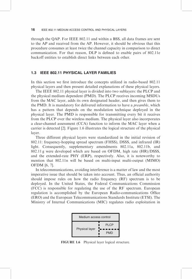
The IEEE 802.11 physical layer is divided into two sublayers: the PLCP andthe physical medium dependent (PMD). The PLCP receives incoming MSDUsfrom the MAC layer, adds its own designated header, and then gives them tothe PMD. It is mandatory for delivered information to have a preamble, whichhas a pattern that depends on the modulation technique deployed in thephysical layer. The PMD is responsible for transmitting every bit it receivesfrom the PLCP over the wireless medium. The physical layer also incorporatesa clear-channel assessment (CCA) function to inform the MAC layer when acarrier is detected [2]. Figure 1.6 illustrates the logical structure of the physicallayer.
Three different physical layers were standardized in the initial revision of802.11: frequency-hopping spread spectrum (FHSS), DSSS, and infrared (IR)light. Consequently, supplementary amendments 802.11a, 802.11b, and802.11 g were developed which are based on OFDM, high rate (HR)/DSSS,and the extended-rate PHY (ERP), respectively. Also, it is noteworthy tomention that 802.11n will be based on multi-input multi-output (MIMO)OFDM [6, 7].
In telecommunications, avoiding interference is a matter of law and the mostimperative issue that should be taken into account. Thus, an official authorityshould impose rules on how the radio frequency (RF) spectrum is to bedeployed. In the United States, the Federal Communications Commission(FCC) is responsible for regulating the use of the RF spectrum. Europeanregulation is accomplished by the European Radio-communications Office(ERO) and the European Telecommunications Standards Institute (ETSI). TheMinistry of Internal Communications (MIC) regulates radio exploitation in
Medium access control
Physical layerPLCP
PMD
FIGURE 1.6 Physical layer logical structure.
16 IEEE 802.11 MEDIUM ACCESS CONTROL AND PHYSICAL LAYERS

Japan. Finally, worldwide regulation is done based upon recommendations ofthe International Telecommunications Union (ITU) [2].
The radio spectrum is partitioned into distinct frequency bands dedicated toparticular applications. Among all frequency bands, the FCC and its counter-parts in other countries designated particular frequency bands for the use ofindustrial, scientific, and medical (ISM) equipment. For instance, the 2.4-GHzband is available worldwide for unlicensed use. The use of RF equipment in theISM bands is usually license free and RF devices operating in such frequencybands typically do not emit significant amounts of radiation. For example,microwave ovens are high-powered home/office devices, but they have exten-sive shielding to restrict interfering radio emissions. WLAN equipment, i.e.,spread-spectrum-based IEEE 802.11b and OFDM-based IEEE 802.11 g, aswell as Bluetooth, spread-spectrum cordless phones, and X105 communicationsystem was developed for the 2.4-GHz ISM band [2]. On the other hand, inaddition to 2.4GHz, the 5-GHz frequency band is another ISM spectrum banddedicated to OFDM-based IEEE 802.11a; The United States was the firstcountry to allow unlicensed device use in the 5-GHz range, though both Japanand Europe followed.
1.3.1 IEEE 802.11 Spread-Spectrum-Based Physical Layers
In this section, we start the discussion of the 802.11 SS–based physical layerwith a short introduction of the system concept of different spread-spectrumarchitectures; then, FH 802.11 and the popular 802.11b extension based onDSSS and HR/DSSS will be covered separately.
1.3.1.1 Overview of Spread Spectrum. Spread-spectrum techniques aremethods by which energy generated at one or more discrete frequencies isdeliberately spread or distributed in either the frequency or time domain. Thisis accomplished for a variety of goals, including establishing secure commu-nications, increasing resistance to natural interference and jamming, andpreventing detection. Spread-spectrum telecommunications is a signal-structur-ing technique that utilizes direct sequence (DS), FH, or a hybrid of these andcan be used for multiple access and/or multiple functions. This techniquereduces the potential interference to other receivers while achieving privacy.Spread spectrum generally makes use of a sequential noiselike signal structure(i.e., spreading code) to broaden the narrowband information signal overrelatively wideband radio frequencies. The intended receiver correlates the
5X10 is an international and open industry standard for communication among devices used for
home automation and domotic. It primarily uses power line wiring for signaling and control, where
the signals involve brief RF bursts representing digital information. A radio-based transport is also
defined. X10 was developed in 1975 by Pico Electronics of Glenrothes, Scotland, in order to allow
remote control of home devices and appliances. It was the first domotic technology and remains the
most widely available. Domotics is the application of computer and/or robotic technology to
household appliances and buildings.
1.3 IEEE 802.11 PHYSICAL LAYER FAMILIES 17
received signals to retrieve the original information signal. Originally, therewere two motivations regarding the spread-spectrum concept: to resist effortsto jam radio communications and to hide the fact that communication is takingplace, sometimes called low probability of intercept (LPI). Ultra wideband(UWB) is another modulation technique that accomplishes the same purposebased on transmitting short duration pulses. IEEE 802.11 uses either FHSS orDSSS in its radio interface. FH systems jump from one frequency to another ina random pattern, transmitting a short burst at each subchannel. The 2-MbpsFH physical layer is specified in clause 14. On the other hand, direct-sequencesystems spread the power out over a wider frequency band using mathematicalcoding functions. Two DS structures were specified. The initial specification inclause 15 standardized a 2-Mbps physical layer, and 802.11b added clause 18for the HR/DSSS physical layer.
1.3.1.1.1 Frequency-Hopping Spread Spectrum. FHSS is a method oftransmitting radio signals by rapidly switching a carrier6 among manyfrequency channels using a pseudorandom7 sequence known to both transmit-ter and receiver. FH is similar to the well-known frequency division multipleaccess (FDMA) but with a key difference. In FDMA systems, devices areallocated fixed orthogonal nonoverlapping frequencies (i.e., fixed while totallydistinct center frequencies and bandwidths). On the other hand, in FH-basedsystems, the frequency is time dependent; each frequency is used for a shortportion of time, i.e., the so-called dwell time.
If two FH systems want to share the same frequency band, both of them canbe configured such that they utilize different hopping sequences so that they donot interfere with each other. For the duration of each time slot, theaforementioned hopping sequences should be on dissimilar frequency slots.As long as the systems stay on different frequency slots, they do not encounterany interfere due to the other party. In general, orthogonal hopping sequencesmaximize wireless network throughput while increasing system complexity.
Beacon frames on FH networks include a timestamp and the so-called FHParameter Set element. The FH Parameter Set element includes the hop patternnumber and a hop index. By receiving a Beacon frame, a station knowseverything it needs to synchronize its hopping pattern.
6A carrier wave, or simply carrier, is a waveform that is modulated to represent the information to
be transmitted. This carrier wave is usually of much higher frequency than the baseband modulating
signal, i.e., the signal which contains the information.7A pseudorandom process is a process that appears stochastic but is not. Pseudorandom sequences
typically exhibit statistical randomness while being generated by an entirely deterministic causal
process. Such a process is easier to produce than a genuine random one and has the benefit that it
can be used again and again to produce exactly the same numbers, useful for testing and fixing
software. To date there is no known method to produce true randomness. The random-number
generation functions provided in many software packages are pseudorandom.
18 IEEE 802.11 MEDIUM ACCESS CONTROL AND PHYSICAL LAYERS

Finally, it is noteworthy to mention that adaptive frequency hopping (AFH)spread spectrum, as used in Bluetooth, enhances system resistance to RFinterference by avoiding using crowded frequencies in the hopping sequence.This sort of adaptive modulation is much easier to implement with FHSS thanwith DSSS.
1.3.1.1.2 Direct-Sequence Spread Spectrum. DS transmission is an alter-native spread-spectrum technique that might be utilized to transmit a narrow-band signal over a much wider frequency band. The fundamental approach ofDS schemes is to cautiously spread the RF energy over a wide frequency band.The DS modulation scheme is accomplished by applying a chipping sequence(CS) to the information bit stream. A chip is a binary digit sequence employedby the DS system. These bits are higher level data while the chip signals arebinary numbers used in encoding (transmitter side) and decoding (receiver side)procedures. Chipping streams, or the so-called pseudorandom noise (PN)codes, should have a much higher rate in comparison to the actual data stream.
For the PN code, IEEE 802.11 adopted an 11-bit Barker word meaning thateach bit is encoded using the entire Barker word as a CS. Barker words havesatisfactory autocorrelation, implying that the correlation function at thereceiver operates as expected in a wide range of environments and is relativelytolerant to multipath delay spreads as incurred in multipath fading channels.The philosophy behind the deployment of exactly 11 bits is that mostregulatory authorities usually necessitate a 10-dB processing gain in DSsystems.
1.3.1.2 IEEE 802.11 FH Physical Layer. In 802.11 FH, the microwave ISMband is partitioned into a series of 1-MHz channels. Approximately 99% of theradio energy is confined to the channel. The modulation scheme employed by802.11 encodes data bits as shifts in the transmission frequency from thechannel center. Channels are defined by their center frequencies, which begin at2.400GHz for channel 0. Successive channels are derived by adding 1-MHzsteps, meaning that channel 1 has a center frequency of 2.401GHz, channel 2has a center frequency of 2.402GHz, etc., until channel 95, which has a centerfrequency at 2.495GHz. Different regulatory authorities allow use of differentparts of the ISM band. For example, the FCC in the United States and theETSI in Europe (excluding France and Spain) allow channels 2–79 to bedeployed while, in Japan, channels 73–95 might be utilized [1, 2].
The dwell time (see Section 1.3.1.1.1) in 802.11 FH systems is 390 time units,which is about 0.4 s. When an 802.11 FH physical layer hops between channels,the hopping process should take no longer than 224 ms. The frequency hops aresubject to extensive regulation, in terms of both the size of each hop and therate at which hops must occur [2].
1.3.1.3 IEEE 802.11b Physical Layer. The IEEE 802.11b amendment tothe original standard was ratified in September 1999. 802.11b has a maximum
1.3 IEEE 802.11 PHYSICAL LAYER FAMILIES 19
raw data rate of 11 Mbps and uses the same CSMA/CA media access methoddefined in the original standard.
IEEE 802.11b products appeared on the market very quickly, since 802.11bis a direct extension of the DSSS modulation technique defined in the originalstandard. The 802.11b standard uses complementary code keying (CCK) as itsmodulation technique, which is a variation on code division multiple access(CDMA). Hence, chipsets and products were easily upgraded to support the802.11b enhancements. The dramatic increase in throughput of 802.11b(compared to the original standard) along with substantial price reductionsled to the rapid acceptance of 802.11b as the definitive WLAN technology.
Generally, 802.11b is used in point-to-multipoint configuration, wherein anAP communicates via an omnidirectional antenna with one or more clients thatare located in a coverage area around the AP. Typical indoor range is 30m(100 ft) at 11 Mbps and 90m (300 ft) at 1 Mbps. With high gain externalantennas, the protocol can also be used in fixed point-to-point arrangements,typically at ranges up to 8 km (5 miles), although some report success at rangesup to 80–120 km (50–75 miles) where line of sight (LOS) can be established.This is usually accomplished in place of costly leased lines or very cumbersomemicrowave communications equipment.
Channels for the 802.11b DS physical layer are much larger than thechannels for the FH physical layer. The DS physical layer has 14 channels inthe 2.4-GHz band, each 5MHz wide. Channel 1 is placed at 2.412GHz,channel 2 at 2.417GHz, and so on, up to channel 13 at 2.472GHz.Channel 14was defined for operation in Japan and has a center frequency that is 12MHzfrom the center frequency of channel 13 [2].
1.3.2 IEEE 802.11 OFDM-Based Physical Layers
In this section, we begin our discussion of 802.11 OFDM-based physical layerswith a qualitative introduction to the basis of OFDM; subsequently, different802.11 extensions, including 802.11a, g, h, and j, are covered separately.
1.3.2.1 Overview of OFDM. OFDM, essentially identical to coded OFDM(COFDM), is a digital multicarrier modulation scheme which deploys a largenumber of closely spaced orthogonal subcarriers. Each subcarrier is modulatedwith a conventional modulation scheme, e.g., quadrature amplitude modula-tion (QAM), at a low symbol rate, maintaining data rates similar to conven-tional single-carrier modulation schemes in the same bandwidth. In practice,OFDM signals are generated by the use of the fast Fourier transform (FFT)algorithm. The most important advantage of OFDM over single-carrierschemes is its ability to cope with severe channel conditions, e.g., multipathand narrowband interference, without complex equalization filters. Channelequalization is simplified due to the fact that OFDM may be viewed as usingmany slowly modulated narrowband signals rather than one rapidly modulatedwideband signal. The orthogonality of the subcarriers results in zero cross-talk,
20 IEEE 802.11 MEDIUM ACCESS CONTROL AND PHYSICAL LAYERS

even though they are so close that their spectra overlap. Low symbol rate helpsmanage time domain spreading of the signal by allowing the use of a guardinterval between successive symbols. The guard interval eliminates the need fora pulse-shaping filter.
OFDM necessitates a high level of accuracy in frequency synchronizationbetween the receiver and transmitter. In other words, any deviation causes thesubcarriers to no longerbe orthogonal, resulting in intercarrier interference(ICI) and cross-talk between adjacent subcarriers. Frequency offsets aretypically caused by mismatched transmitter and receiver oscillators or byDoppler shift due to mobile device movement. While Doppler shift alonemay be compensated for by the receiver, the situation is worsened whencombined with multipath, as reflections will appear at various frequencyoffsets, which is much harder to correct. This effect typically worsens as speedincreases and is an important factor limiting the use of OFDM in high speedvehicles. Several techniques for ICI suppression have been suggested, but theymay increase receiver complexity as well.
A key principle of OFDM is that, due to low symbol rate modulation,symbols are relatively longer than the channel time characteristics. As a result,it suffers less from intersymbol interference (ISI) caused by multipath. Since theduration of each symbol is long enough, it is feasible to insert a guard intervalbetween the consecutive OFDM symbols, thus eliminating ISI. In addition, theguard interval also reduces the sensitivity to time synchronization problems.The cyclic prefix, which is transmitted during the guard interval, consists of theend of the OFDM symbol copied into the guard interval, and the guard intervalis transmitted followed by the OFDM symbol. The guard interval consists of acopy of the end of the OFDM symbol so that the receiver will integrate over aninteger number of sinusoid cycles for each multipath when it performs OFDMdemodulation with FFT.
The stochastic effects due to channel frequency selectivity might be con-sidered to be constant over an OFDM subchannel if the subchannel issufficiently narrowbanded, i.e., if the number of subchannels is adequatelylarge. This important feature makes equalization far simpler at the receiver sidein OFDM systems than in conventional single-carrier modulation schemes. Theequalizer simply has to multiply each subcarrier by a constant value, or even ararely variable value. In addition, some subcarriers in some OFDM symbolsmight carry pilot signals for measurement of channel conditions, i.e., theequalizer gain for each subcarrier. In addition, pilot signals might be usedfor synchronization. If a differential modulation technique such as differentialphase shift keying (DPSK) or differential quadrature phase shift keying(DQPSK) is applied to each subcarrier, equalization can be completely omitted,since these schemes are insensitive to slowly changing amplitude and phasedistortion.
OFDM has being perpetually exploited in conjunction with channel codingschemes, i.e., forward error correction (FEC), and almost always usesfrequency and/or time interleaving. On the one hand, frequency (subcarrier)
1.3 IEEE 802.11 PHYSICAL LAYER FAMILIES 21

interleaving increases resistance to channel frequency selectivity. On the otherhand, time interleaving ensures that bits that are initially close together in thebit stream are transmitted far apart in time, thus mitigating against severefading, as would happen when traveling at high speed. However, timeinterleaving is of little benefit in slowly fading channels while frequencyinterleaving offers little to no benefit for narrowband channels that sufferfrom flat fading. The reason interleaving is used in OFDM is to attempt tospread the errors out in the bit stream presented to the error correction decoder.A common type of error correction coding scheme used with OFDM-basedsystems is convolutional coding, which is often concatenated with Reed–Solomon coding. Convolutional coding is used as the inner code and Reed–Solomon coding is used for the outer code, usually with additional interleavingon top of the time and frequency interleaving and between the two layers ofcoding. The motivation for this combination of error correction coding is thatthe Viterbi decoder used for convolutional decoding produces short errorbursts when there is a high concentration of errors, and Reed–Solomon codesare inherently well suited to correcting bursts of errors.
Finally, it should be noted that windowing is another technique which helpsOFDM-based transceivers cope with real-world effects. Transitions can beabrupt at symbol boundaries, causing a large number of undesired highfrequency components. To make OFDM transmitters robust against theaforementioned problems, it is widespread to add padding bits at the beginningand end of transmissions to allow transmitters to ramp up and down from fullpower. Padding bits are frequently required when error correction coding isdeployed. In the literature, padding streams are usually referred to as trainingsequences.
1.3.2.2 IEEE 802.11a/h/j 5-GHz Physical Layer. The IEEE 802.11aamendment to the original standard was ratified in September 1999 [8].Basically, it utilizes the same core protocol as the original standard, operatesin the 5-GHz band, and uses a 52-subcarrier OFDM with a maximum raw datarate of 54 Mbps, which yields realistic net achievable throughput in the mid-20Mbps. The data rate is reduced to 48, 36, 24, 18, 12, 9, and then 6 Mbps ifrequired. 802.11a has 12 nonoverlapping channels, 8 dedicated to indoor and4 to point to point. It is not interoperable with 802.11b, except if usingequipment that implements both standards. Due to the fact that the 2.4-GHzfrequency band has been heavily deployed, operating in the 5-GHz band gives802.11a the advantage of less interference. However, this high carrier frequencyalso brings disadvantages. It restricts the use of 802.11a to almost LOS,necessitating more AP deployment [2, 9].
In IEEE 802.11a, out of 52 OFDM subcarriers, 48 are for data and 4 arepilot subcarriers with a carrier separation of 0.3125MHz (20MHz/64). Each ofthese subcarriers can be binary phase shift keying (BPSK), quadrature phaseshift keying (QPSK), 16-QAM, or 64-QAM. The total bandwidth is 20MHzwith an occupied bandwidth of 16.6MHz and symbol duration is 4 ms with a
22 IEEE 802.11 MEDIUM ACCESS CONTROL AND PHYSICAL LAYERS
guard interval of 0.8 ms. The generation and decoding of orthogonal compo-nents are done in baseband using digital signal processing (DSP), which is thenup converted to 5GHz at the transmitter. Each subcarrier could be representedas a complex number. The time domain signal is generated by taking an inversefast Fourier transform (IFFT). Correspondingly, the receiver down convertssamples at 20MHz and does an FFT to retrieve the original coefficients. Theadvantages of using OFDM include reduced multipath effects in reception andincreased spectral efficiency [9].
In 802.11a, channels in the 5-GHz band are numbered starting every 5MHzand each 20-MHz 802.11a channel occupies four channel numbers. Basically,802.11a was originally designed for the United States. European channelizationwas added as part of 802.11 h in late 2003, and subsequently Japaneseoperation was appended with 802.11j in late 2004 [2].
1.3.2.3 IEEE 802.11 g 2.4-GHz Physical Layer. In June 2003, a thirdmodulation standard was ratified: 802.11 g. This extension exploits the2.4-GHz frequency band (similar to 802.11b) but operates at a maximumraw data rate of 54 Mbps, or about 24.7 Mbps net throughput, similar to802.11a. IEEE 802.11 g hardware is compatible with its 802.11b counterpart.The modulation scheme used in 802.11 g is OFDM for the data rates of 6, 9, 12,18, 24, 36, 48, and 54 Mbps, and, on the one hand, reverts to CCK to achieve5.5 and 11 Mbps while, on the other hand, switches to DBPSK/DQPSK+DSSS for 1 and 2 Mbps. The maximum range of 802.11 g devicesis slightly greater than that of 802.11b devices, but the range in which a clientcan achieve the full 54-Mbps data rate is much shorter than that which a802.11b client can reach, 11 Mbps.
1.3.3 IEEE 802.11n Physical Layer
The emerging IEEE 802.11n specification differs from its predecessors in that itprovides for a variety of optional modes and configurations that dictatedifferent maximum raw data rates. This enables the standard to offer baselineperformance parameters for all 802.11n devices while allowing manufacturersto enhance or tune capabilities to accommodate different applications and pricepoints. With every possible option enabled, 802.11n could offer raw data ratesup to 600 Mbps [6, 7].
In fact, the most widely celebrated component of 802.11n is the inclusion ofMIMO technology. MIMO harnesses multipath transmission with a techniqueknown as space division multiplexing. The wireless terminal basically splits adata stream into multiple concurrent divisions, called spatial streams, anddelivers each one of them through separate antennas to corresponding antennason the receiving end. The current 802.11n draft provides for up to four spatialstreams, even though compliant hardware is not required to support that many.Doubling the number of spatial streams from one to two effectively doublesthe raw data rate. There are trade-offs, however, such as increased power
1.3 IEEE 802.11 PHYSICAL LAYER FAMILIES 23

consumption and, to a lesser extent, cost. The 802.11n specification will includea MIMO power-saving mode which mitigates power consumption by usingmultiple paths only when communication would benefit from the additionalperformance. The MIMO power-saving mode is expected to be a compulsoryfeature in the ratified IEEE 802.11n final specifications. A non compulsorymode in 802.11n that effectively doubles the offered data rate is deployment ofthe communication channel of 40MHz bandwidth. The main trade-off here isless channel availability for other mobile stations. In the case of the 2.4-GHzfrequency band, there is enough room for three nonoverlapping 20-MHzchannels. Needless to say, a 40-MHz channel does not leave much room forother devices to join the network or transmit in the same airspace. This meansthat dynamic radio resource management is critical to ensure that the 40-MHzchannel option improves the overall system performance by balancing the highbandwidth demands of some clients with the needs of other clients to remainconnected to the network [2].
Note that in the MAC layer IEEE 802.11n offers BAs similar to theconcepts recommended in the 802.11e amendment. By removing the needfor one ACK for every data frame, the amount of overhead required for theACK frames, as well as preamble and framing, is considerably reduced.BAs are helpful, but only if all the frames in a burst can be delivered withoutany problem. Missing one frame in the block or losing the ACK itself carries asteep penalty in protocol operations since the entire block must be retrans-mitted again. In addition, in 802.11n MAC, frame aggregation is alsoexpected to be a mandatory MAC entity component. Combining severalsmall layer 3 packets into a single relatively large frame improves the data-to-overhead ratio. Frame aggregation is often used with MAC header compres-sion, since the MAC header on multiple frames to the same destination isquite similar.
1.4 SUMMARY AND CONCLUDING REMARKS
In this chapter, a brief overview of existing MAC and physical layers inWLANs was provided. Starting from the MAC layer, we reviewed the well-known IEEE 802.11 and its QoS-aware amendment 802.11e. We pursued ourdiscussion of the IEEE 802.11 physical layer, and different types of physicallayers with diverse system architectures and modulation schemes wereexplored.
ACKNOWLEDGMENTS
This work was partially supported by Nokia Foundation and ElisaFoundation.
24 IEEE 802.11 MEDIUM ACCESS CONTROL AND PHYSICAL LAYERS
REFERENCES
1. IEEE 802.11 WG, Part 11: ‘‘Wireless LAN medium access control (MAC) and
physical layer (PHY) specification,’’ IEEE, New York, Aug. 1999.
2. M. Gast, 802.11 Wireless Networks: The Definitive Guide, 2nd ed., O’Reilly Media
Inc., 2005.
3. IEEE 802.11e, Part 11: ‘‘Wireless LAN medium access control (MAC) and physical
layer (PHY) specifications: amendment 8: Medium access control (MAC) quality of
service enhancements,’’ supplement to IEEE 802.11, IEEE, New York, Nov. 2005.
4. S. Mangold, S. Choi, G. R. Hiertz, O. Klein, and B. Walke, ‘‘Analysis of IEEE
802.11e for QoS support in wireless LANs,’’ IEEE Wireless Commun. 10(6), 40–50
(2003).
5. Y. Xiao, ‘‘IEEE 802.11e: a QoS provisioning at the MAC layer,’’ IEEE Wireless
Commun. 11(3), 72–79 (2004).
6. Y. Xiao, ‘‘IEEE 802.11N: enhancements for higher throughput in wireless LAN,’’
IEEE Wireless Commun. 12(6), 82–91 (2005).
7. Y. Xiao, ‘‘Efficient MAC strategies for the IEEE 802.11n wireless LANs,’’ Wireless
Commun. Mobile Comput. 6(4), 453–466 (2006).
8. IEEE 802.11b, Part 11: ‘‘Wireless LAN medium access control (MAC) and physical
layer (PHY) specifications: High-speed physical layer extension in the 2.4GHz
band,’’ supplement to IEEE 802.11, IEEE, New York, Sept. 1999.
9. IEEE 802.11a WG, Part 11: ‘‘Wireless LAN medium access control (MAC) and
physical layer (PHY) specification: high-speed physical layer in the 5GHz band,’’
IEEE, New York, Sept. 1999.
REFERENCES 25
