chapter 1 introduction -...
TRANSCRIPT
CHAPTER 1
INTRODUCTION
This book provides a tutorial description of the mathematical models andequation formulations that are required for the study of a special class ofdynamic power system problems, namely subsynchronous resonance(SSR). Systems that experience SSR exhibit dynamic oscillations atfrequencies below the normal system base frequency (60 Hz in NorthAmerica). These problems are of great interest in utilities where thisphenomenon is a problem, and the computation of conditions that excitethese SSR oscillations are important to those who design and operate thesepower systems.
This book presents the mathematical modeling of the power system, whichis explained in considerable detail. The data that are required to supportthe mathematical models are discussed, with special emphasis on fieldtesting to determine the needed data. However, the purpose of modeling isto support mathematical analysis of the power system. Here, we areinterested in the oscillatory behavior of the system, and the damping ofthese oscillations. A convenient method of analysis to determine thisdamping is to compute the eigenvalues of a linear model of the system.Eigenvalues that have negative real parts are damped, but those withpositive real parts represent resonant conditions that can lead tocatastrophic results. Therefore, the computation of eigenvalues andeigenvectors for the study of SSR is an excellent method of providing crucialinformation about the nature of the power system. The method forcomputing eigenvalues and eigenvectors is presented, and theinterpretation of the resulting information is described.
1.1 DEFINITION OF SSRSubsynchronous resonance (SSR) is a dynamic phenomenon of interest inpower systems that have certain special characteristics. The formaldefinition of SSR is provided by the IEEE [1]:
Subsynchronous resonance is an electric power system conditionwhere the electric network exchanges energy with a turbinegenerator at one or more of the natural frequencies of the combinedsystem below the synchronous frequency of the system.
The definition includes any system condition that provides the opportunityfor an exchange of energy at a given subsynchronous frequency. This

4 SUBSYNCHRONOUS RESONANCE IN POWER SYSTEMS
includes what might be considered "natural" modes of oscillation that aredue to the inherent system characteristics, as well as "forced" modes ofoscillation that are driven by a particular device or control system.
The most. common example of the natural mode of subsynchronousoscillation is due to networks that include series capacitor compensatedtransmission lines. These lines, with their series LC combinations, havenatural frequencies co that are defined by the equation
where con is the natural frequency associated with a particular line L Cproduct, coB is the system base frequency, and XL and Xc are the inductiveand capacitive reactances, respectively. These frequencies appear to thegenerator rotor as modulations of the base frequency, giving bothsubsynchronous and supersynchronous rotor frequencies. It is thesubsynchronous frequency that may interact with one of the naturaltorsional modes of the turbine-generator shaft, thereby setting up theconditions for an exchange of energy at a subsynchronous frequency, withpossible torsional fatigue damage to the turbine-generator shaft.
The torsional modes (frequencies) of shaft oscillation are usually known, ormay be obtained from the turbine-generator manufacturer. The networkfrequencies depend on many factors, such as the amount of seriescapacitance in service and the network switching arrangement at aparticular time. The engineer needs a method for examining a largenumber of feasible operating conditions to determine the possibility of SSRinteractions. The eigenvalue program provides this tool. Moreover, theeigenvalue computation permits the engineer to track the locus of systemeigenvalues as parameters such as the series capacitance are varied torepresent equipment outages. If the locus of a particular eigenvalueapproaches or crosses the imaginary axis, then a critical condition isidentified that will require the application of one or more SSRcountermeasures [2].
1.2 POWER SYSTEM MODELINGThis section presents an overview of power system modeling and definesthe limits of modeling for the analysis of SSR. We are interested here inmodeling the power system for the study of dynamic performance. Thismeans that the system is described by a system of differential equations.
INTRODUCTION 5
Usually, these equations are nonlinear, and the complete description of thepower system may require a very large number of equations. For example,consider the interconnected network of the western United States, from theRockies to the Pacific, and the associated generating sources and loads.This network consists of over 3000 buses and about 400 generating stations,and service is provided to about 800 load points. Let us assume that thenetwork and loads may be defined by algebraic models for the analyticalpurpose at hand. Moreover, suppose that the generating stations can bemodeled by a set of about 20 first order differential equations. Such aspecification, which might be typical of a transient stability analysis, wouldrequire 8000 differential equations and about 3500 algebraic equations. Avery large number of oscillatory modes will be present in the solution. Thismakes it difficult to understand the effects due to given causes because somany detailed interactions are represented.
Power system models are often conveniently defined in terms of the majorsubsystems of equipment that are active in determining the systemperformance. Figure 1.1 shows a broad overview of the bulk power system,including the network, the loads, the generation sources, the systemcontrol, the telecommunications, and the interconnections withneighboring utilities. For SSR studies we are interested in the prime mover(turbines) and generators and their primary controls, the speed governorsand excitation systems. The network is very important and is representedin detail, but using only algebraic equations and ordinary differentialequations (lumped parameters) rather than the exact partial differentialequations. This is because we are interested only in the low frequencyperformance of the network, not in traveling waves. The loads may beimportant, but are usually represented as constant impedances in SSRmodeling. We are not interested in the energy sources, such as boilers ornuclear reactors, nor are we concerned about the system control center,which deals with very low frequency phenomena, such as daily loadtracking. These frequencies are too low for concern here.
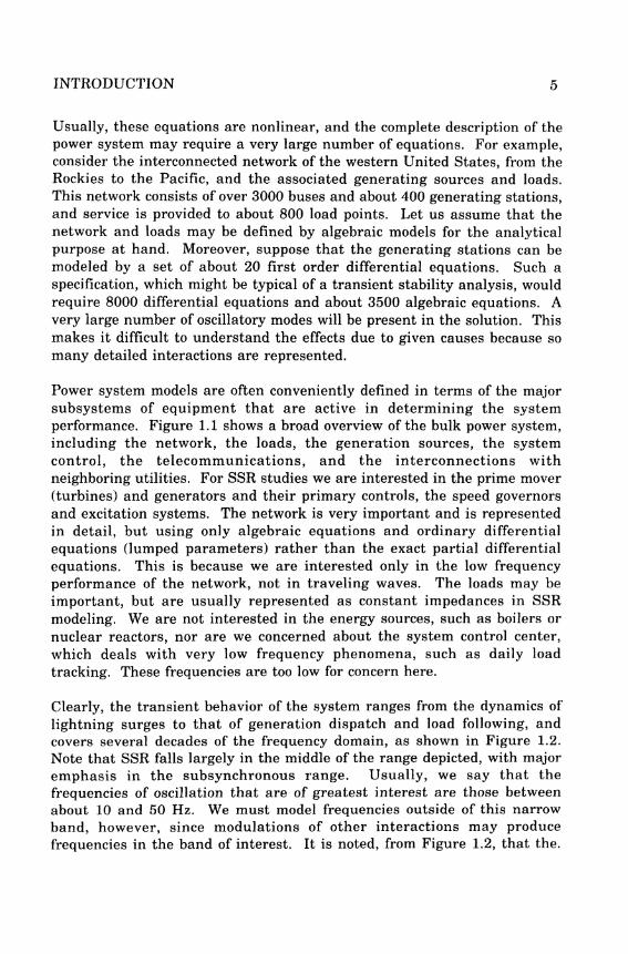
Clearly, the transient behavior of the system ranges from the dynamics oflightning surges to that of generation dispatch and load following, andcovers several decades of the frequency domain, as shown in Figure 1.2.Note that SSR falls largely in the middle of the range depicted, with majoremphasis in the subsynchronous range. Usually, we say that thefrequencies of oscillation that are of greatest interest are those betweenabout 10 and 50 Hz. We must model frequencies outside of this narrowband, however, since modulations of other interactions may producefrequencies in the band of interest. It is noted, from Figure 1.2, that the.

Figure 1.1 Structure of a Power System for Dynamic Analysis
basic range of frequencies of interest is not greatly different from transientstability. Hence, many of the models from transient stability will beappropriate to use.
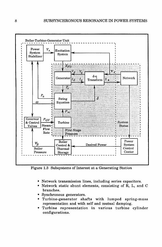
In modeling the system for analysis, we find it useful to break the entiresystem up into physical subsystems, as in Figure 1.3, which shows themajor subsystems associated with a single generating unit and itsinterconnection with the network and controls. In SSR analysis, it isnecessary to model most, but not all, of these subsystems, and it isnecessary to model at least a portion of the network. The subset of thesystem to be modeled for SSR is labeled in Figure 1.3, where the shadedregion is the subset of interest in many studies. Also, it is usuallynecessary to model several machines for SSR studies, in addition to theinterface between each machine and the network.
6 SUBSYNCHRONOUS RESONANCE IN POWER SYSTEMS
Other J i. r-\ JGenerators 1 ; ; :
Voltage | j i IControl j j j System !
—J . - * _ | ; | Transmission —r-j-H > O t h e r
Prime j ' ' V ; ; ; Network j j SystemsMover p 1 i | i • j
r ^ J r Generator .' j j j \ \
Energy p-i 1| ; j j j : j ISource h r | i ; : | I T" ^^v"^
,—L. Energy I 1 ' v y _. T .| 1 Source Speed System T^e L m e
h H Control Control Loads P o w e r
111vLJ^> Generated
A r* • J PowerDesired
Generation y yControl | ' * 1
I §iS22k System Control Center ^Eliem
FrequencySystem ^ 4 Tie Line* "
Frequency L _ I Power \ IReferenceJ ScheduleJ
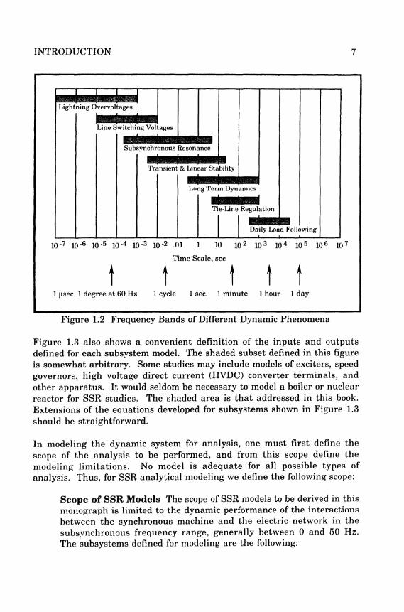
Figure 1.2 Frequency Bands of Different Dynamic Phenomena
Figure 1.3 also shows a convenient definition of the inputs and outputsdefined for each subsystem model. The shaded subset defined in this figureis somewhat arbitrary. Some studies may include models of exciters, speedgovernors, high voltage direct current (HVDC) converter terminals, andother apparatus. It would seldom be necessary to model a boiler or nuclearreactor for SSR studies. The shaded area is that addressed in this book.Extensions of the equations developed for subsystems shown in Figure 1.3should be straightforward.
In modeling the dynamic system for analysis, one must first define thescope of the analysis to be performed, and from this scope define themodeling limitations. No model is adequate for all possible types ofanalysis. Thus, for SSR analytical modeling we define the following scope:
Scope of SSR Models The scope of SSR models to be derived in thismonograph is limited to the dynamic performance of the interactionsbetween the synchronous machine and the electric network in thesubsynchronous frequency range, generally between 0 and 50 Hz.The subsystems defined for modeling are the following:
INTRODUCTION 7
Lightning Overvoltages
Line Switching Voltages
Subsynchronous Resonance
Transient & Linear Stability
Long Term Dynamics
Tie-Line Regulation
Daily Load Following
10"7 10"6 10"5 10-4 10"3 lO"2 .01 1 10 102 103 104 105 106 107
Time Scale, sec
1 1 1 1 11 jisec. 1 degree at 60 Hz 1 cycle 1 sec. 1 minute 1 hour 1 day
SUBSYNCHRONOUS RESONANCE IN POWER SYSTEMS
• Network transmission lines, including series capacitors.• Network static shunt elements, consisting of R, L, and C
branches.• Synchronous generators.• Turbine-generator shafts with lumped spring-mass
representation and with self and mutual damping.• Turbine representation in various turbine cylinder
configurations.
Boiler-Turbine-Generator Unit
! P ^ e r Vs E x c i t a t i o n ISystem >- g -< , ,
[ Stabilizer [
; : I ^ i^ v? r iJV t ' : | 1:• ! G e n e r a t o r / r f / ^ T r a n r f b r m I*\:''.\
N e t W ° r k |
; p ° ; I I s ; :
i i ._ Swing O i : - ,, CO ^ Equation , '
: | pv : ";i Governor PQV ' ' !! & Control ^ - Turbine [ System i| Valves Steam> _ _ _ ^ ^ _ i Status \; i Flow; I P i r s t s t a g e ; .j Rate ; Pressure ! , . <| ^ " - 1 f - ' - ' - - - • - - - - » " - - - • < • • - • * . - - - , - - - " - ^ f - - - - '
! w I Boiler I ! PowerI I P Control & ^ Desired Power t
)__ Systemi Boiler Thermal > Control! Pressure Storage i Center
Figure 1.3 Subsystems of Interest at a Generating Station

INTRODUCTION 9
It is also necessary to define the approximate model bandwidth consideredessential for accurate simulated performance of the system under study.For the purpose here, models will be derived that have a bandwidth of about60 Hz.
1.3 INTRODUCTION TO SSRSubsynchronous resonance is a condition that can exist on a power systemwherein the network has natural frequencies that fall below the nominal 60hertz of the network applied voltages. Currents flowing in the ac networkhave two components; one component at the frequency of the drivingvoltages (60 Hz) and another sinusoidal component at a frequency thatdepends entirely on the elements of the network. We can write a generalexpression for the current in a simple series R-L-C network as
i(t) = #[Asin(aV + ^ ) + Be'*"2' sin((o2t + y/2)] (
where all of the parameters in the equation are functions of the networkelements except co{, which is the frequency of the driving voltages of all thegenerators. Note that even co2 is a function of the network elements.
Currents similar to (1.2) flow in the stator windings of the generator andare reflected into the generator rotor a physical process that is describedmathematically by Park's transformation. This transformation makes the60 hertz component of current appear, as viewed from the rotor, as a dccurrent in the steady state, but the currents of frequency &)2
a r e
transformed into currents of frequencies containing the sum (co{+co2) anddifference {cox-(o2) of the two frequencies. The difference frequencies arecalled subsynchronous frequencies. These subsynchronous currentsproduce shaft torques on the turbine-generator rotor that cause the rotor tooscillate at subsynchronous frequencies.
The presence of subsynchronous torques on the rotor causes concernbecause the turbine-generator shaft itself has natural modes of oscillationthat are typical of any spring mass system. It happens that the shaftoscillatory modes are at subsynchronous frequencies. Should the inducedsubsynchronous torques coincide with one of the shaft natural modes ofoscillation, the shaft will oscillate at this natural frequency, sometimeswith high amplitude. This is called subsynchronous resonance, which cancause shaft fatigue and possible damage or failure.
10 SUBSYNCHRONOUS RESONANCE IN POWER SYSTEMS
1.3.1 Types of SSR InteractionsThere are many ways in which the system and the generator may interactwith subsynchronous effects. A few of these interactions are basic inconcept and have been given special names. We mention three of these thatare of particular interest:
Induction Generator EffectTorsional Interaction EffectTransient Torque Effect
Induction Generator EffectInduction generator effect is caused by self excitation of the electricalsystem. The resistance of the rotor to subsynchronous current, viewedfrom the armature terminals, is a negative resistance. The network alsopresents a resistance to these same currents that is positive. However, ifthe negative resistance of the generator is greater in magnitude than thepositive resistance of the network at the system natural frequencies, therewill be sustained subsynchronous currents. This is the condition known asthe "induction generator effect."
Torsional InteractionTorsional interaction occurs when the induced subsynchronous torque inthe generator is close to one of the torsional natural modes of the turbine-generator shaft. When this happens, generator rotor oscillations will buildup and this motion will induce armature voltage components at bothsubsynchronous and supersynchronous frequencies. Moreover, theinduced subsynchronous frequency voltage is phased to sustain thesubsynchronous torque. If this torque equals or exceeds the inherentmechanical damping of the rotating system, the system will become self-excited. This phenomenon is called "torsional interaction."
Transient TorquesTransient torques are those that result from system disturbances. Systemdisturbances cause sudden changes in the network, resulting in suddenchanges in currents that will tend to oscillate at the natural frequencies ofthe network. In a transmission system without series capacitors, thesetransients are always dc transients, which decay to zero with a timeconstant that depends on the ratio of inductance to resistance. Fornetworks that contain series capacitors, the transient currents will be of aform similar to equation (1.2), and will contain one or more oscillatoryfrequencies that depend on the network capacitance as well as theinductance and resistance. In a simple radial R-L-C system, there will beonly one such natural frequency, which is exactly the situation described in
INTRODUCTION 11
(1.2), but in a network with many series capacitors there will be many suchsubsynchronous frequencies. If any of these subsynchronous networkfrequencies coincide with one of the natural modes of a turbine-generatorshaft, there can be peak torques that are quite large since these torques aredirectly proportional to the magnitude of the oscillating current. Currentsdue to short circuits, therefore, can produce very large shaft torques bothwhen the fault is applied and also when it is cleared. In a real powersystem there may be many different subsynchronous frequencies involvedand the analysis is quite complex.
Of the three different types of interactions described above, the first two maybe considered as small disturbance conditions, at least initially. The thirdtype is definitely not a small disturbance and nonlinearities of the systemalso enter into the analysis. From the viewpoint of system analysis, it isimportant to note that the induction generator and torsional interactioneffects may be analyzed using linear models, suggesting that eigenvalueanalysis is appropriate for the study of these problems.
1,3,2 Analytical ToolsThere are several analytical tools that have evolved for the study of SSR.The most common of these tools will be described briefly.
Frequency ScanningFrequency scanning is a technique that has been widely used in NorthAmerica for at least a preliminary analysis of SSR problems, and isparticularly effective in the study of induction generator effects. Thefrequency scan technique computes the equivalent resistance andinductance, seen looking into the network from a point behind the statorwinding of a particular generator, as a function of frequency. Should therebe a frequency at which the inductance is zero and the resistance negative,self sustaining oscillations at that frequency would be expected due toinduction generator effect.
The frequency scan method also provides information regarding possibleproblems with torsional interaction and transient torques. Torsionalinteraction or transient torque problems might be expected to occur if thereis a network series resonance or a reactance minimum that is very close toone of the shaft torsional frequencies.
Figure 1.4 shows the plot of a typical result from a frequency scan of anetwork [3]. The scan covers the frequency range from 20 to 50 hertz andshows separate plots for the resistance and reactance as a function of

Figure 1.4 Plot from the Frequency Scan of a Network [3]
frequency. The frequency scan shown in the figure was computed for agenerator connected to a network with series compensated transmissionlines and represents the impedance seen looking into that network from thegenerator. The computation indicates that there may be a problem withtorsional interactions at the first torsional mode, which occurs for thisgenerator at about 44 Hz. At this frequency, the reactance of the networkgoes to zero, indicating a possible problem. Since the frequency scanresults change with different system conditions and with the number ofgenerators on line, many conditions need to be tested. The potentialproblem noted in the figure was confirmed by other tests and remedialcountermeasures were prescribed to alleviate the problem [3].
Frequency scanning is limited to the impedances seen at a particular pointin the network, usually behind the stator windings of a generator. Theprocess must be repeated for different system (switching) conditions at theterminals of each generator of interest.
Eigenvalue AnalysisEigenvalue analysis provides additional information regarding the systemperformance. This type of analysis is performed with the network and thegenerators modeled in one linear system of differential equations. Theresults give both the frequencies of oscillation as well as the damping ofeach frequency.
Eigenvalues are defined in terms of the system linear equations, that arewritten in the following standard form.
12 SUBSYNCHRONOUS RESONANCE IN POWER SYSTEMS
400| ; ; 1 ; 1 ; 1 250
g 350 - \ : I \ Q]\ \ - 200 £j
§ 300 - • ^ - -| \ ^ ! > U 1 I :m i 50 %X Reactance I I / *"0 1 \ ; ^.# EJ"
? 25°" H-H-! ^ . - * I 1 r / - 100 |8 ™ ' I->i } ^* i I W - - 50 B-§ iso - ~jf~ \ ---A- ••••; | ] I ¥4 - o .g
1 - -Af ^f^M W -50 i0l i i i i I i i i i I i i i i I i i i i I i i i i I i iY^-ffll-i5Q
20 25 30 35 40 45 50Frequency in Hz

INTRODUCTION 13
Table 1.1
EigenvalueNumber
1,23,45,67,89,10
11
1213,14
15,1617,181920
Computed Eigenvalues for the First
Real Part,s-1
+0.07854636
+0.07818368+0.04089805+0.00232994
-0.00000048
-0.77576318-0.94796049-1.21804111-5.54108044-6.80964255-25.41118956-41.29551248
Imaginary Part,rad/s
±127.15560200±99.70883066±160.38986053±202.86306822±298.17672924
±10.59514740±136.97740321±616.53245850
Benchmark Model
Imaginary Part,Hz
±20.2374426
±15.86915327±25.52683912±32.28666008±47.45630037
±96.61615878±21.80063081±98.12275595
x = Ax + Bu Q.3)
Then the eigenvalues are defined as the solutions to the matrix equation
det[AU-A] = 0 ( 1 4 )
where the parameters A are called the eigenvalues.
An example of eigenvalue analysis is presented using the data from theFirst Benchmark Model, a one machine system used for SSR programtesting [4]. The results of the eigenvalue calculation is shown in Table 1.1.Note that this small system is of 20th order and there are 10 eigenvalues inthe range of 15.87 to 47.46 Hz, which is the range where torsionalinteraction usually occur. Moreover, eight of the eigenvalues have positivereal parts, indicating an absence of damping in these modes of response.
Eigenvalue analysis is attractive since it provides the frequencies and thedamping at each frequency for the entire system in a single calculation.
14 SUBSYNCHRONOUS RESONANCE IN POWER SYSTEMS
EMTP AnalysisThe ElectroMagnetic Transients Program (EMTP) is a program fornumerical integration of the system differential equations. Unlike atransient stability program, which usually models only positive sequencequantities representing a perfectly balanced system, EMTP is a full three-phase model of the system with much more detailed models oftransmission lines, cables, machines, and special devices such as seriescapacitors with complex bypass switching arrangements. Moreover, theEMTP permits nonlinear modeling of complex system components. It is,therefore, well suited for analyzing the transient torque SSR problems.
The full scope of modeling and simulation of systems using EMTP is beyondthe scope of this book. However, to illustrate the type of results that can beobtained using this method, we present one brief example. Figure 1.5shows the torque at one turbine shaft section for two different levels of seriestransmission compensation, a small level of compensation for Case A anda larger level for Case B [5]. The disturbance is a three phase fault at time t= 0 that persists for 0.06 seconds. It is apparent that the Case B, the higherlevel of series compensation, results is considerably torque amplification.This type of information would not be available from a frequency scan orfrom eigenvalue computation, although those methods would indicate theexistence of a resonant condition at the indicated frequency of oscillation.EMTP adds important data on the magnitude of the oscillations as well astheir damping.
SummaryThree prominent methods of SSR analysis have been briefly described.Frequency scanning provides information regarding the impedance seen,as a function of frequency, looking into the network from the stator of agenerator. The method is fast and easy to use. Eigenvalue analysisprovides a closed form solution of the entire network including themachines. This gives all of the frequencies of oscillation as well as thedamping of each frequency. The method requires more modeling and datathan frequency scanning and requires greater computer resources for thecomputation. EMTP requires still greater modeling effort and computerresources, but allows the full nonlinear modeling of the system machinesand other devices, such as capacitor bypass schemes.
In the balance of this book, we concentrate only on the eigenvalue method ofSSR analysis. Most of the book is devoted to the mathematical modeling andthe determination of accurate model parameters for eigenvalue analysis.First, however, we discuss briefly the types of models used for the SSR

Figure 1.5 Typical Computed Generator Shaft Torques (upper 3 traces) andVoltage Across a Series Capacitor (bottom trace) Using EMTP [5]
16 SUBSYNCHRONOUS RESONANCE IN POWER SYSTEMS
analysis. Then we comment briefly on the computed results and their useby the system analyst. Finally, we conclude this chapter with some resultsfrom an actual system study to illustrate the way in which eigenvaluecalculations may be used.
1.4 EIGENVALUE ANALYSISEigenvalue analysis uses the standard linear, state-space form of systemequations and provides an appropriate tool for evaluating system conditionsfor the study of SSR, particularly for induction generator and torsionalinteraction effects.
1.4.1 Advantages of Eigenvalue ComputationThe advantages of eigenvalue analysis are many. Some of the prominentadvantages are:
• Uses the state-space equations, making it possible to utilize manyother analytical tools that use this same equation form
• Compute all the exact modes of system oscillation in a singlecomputation
• Can be arranged to perform a convenient parameter variation tostudy parameter sensitivities
• Can be used to plot root loci of eigenvalue movement in response tomany different types of changes
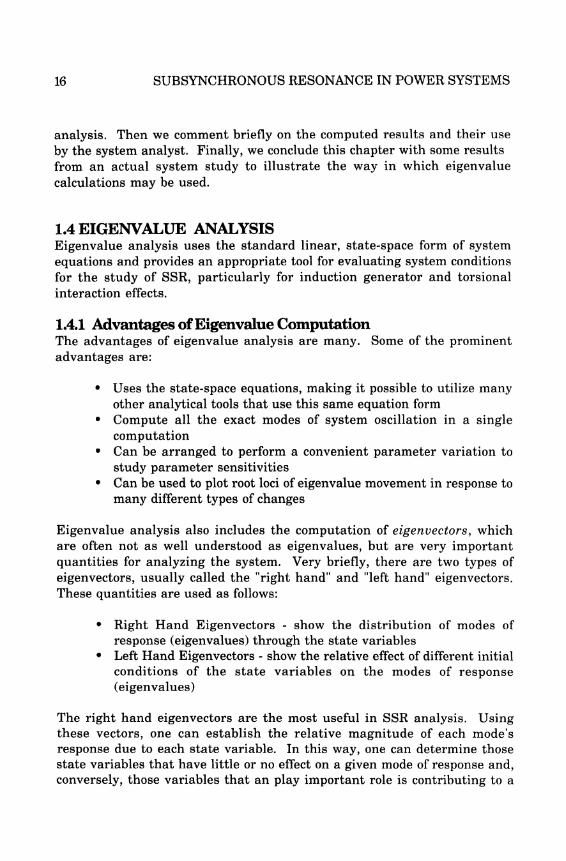
Eigenvalue analysis also includes the computation of eigenvectors, whichare often not as well understood as eigenvalues, but are very importantquantities for analyzing the system. Very briefly, there are two types ofeigenvectors, usually called the "right hand" and "left hand" eigenvectors.These quantities are used as follows:
• Right Hand Eigenvectors - show the distribution of modes ofresponse (eigenvalues) through the state variables
• Left Hand Eigenvectors - show the relative effect of different initialconditions of the state variables on the modes of response(eigenvalues)
The right hand eigenvectors are the most useful in SSR analysis. Usingthese vectors, one can establish the relative magnitude of each mode'sresponse due to each state variable. In this way, one can determine thosestate variables that have little or no effect on a given mode of response and,conversely, those variables that an play important role is contributing to a
INTRODUCTION 17
given response. This often tells the engineer exactly those variables thatneed to be controlled in order to damp a subsynchronous oscillation on agiven unit.
1.4.2 Disadvantages of Eigenvalue CalculationEigenvalue analysis is computationally intensive and is useful only for thelinear problem. Moreover, this type of analysis is limited to relatively smallsystems, say of 500th order or less. Recent work has been done on muchlarger systems, but most of these methods compute only selectedeigenvalues and usually require a skilled and experienced analyst in orderto be effective [8,9]. Work is progressing on more general methods ofsolving large systems, but no breakthroughs have been reported.
Another difficulty of eigenvalue analysis is the general level of difficulty inwriting eigenvalue computer programs. Much work has been done in thisarea, and the SSR analyst can take advantage of this entire realm of effort.Perhaps the most significant work is that performed over the years by theArgonne National Laboratory, which has produced the public domainprogram known as EISPACK [10]. Another program called PALS has beendeveloped by Van Ness for the Bonneville Power Administration, usingsome special analytical techniques [11]. Thus, there are completeprograms available to those who wish to pursue eigenvalue analysiswithout the difficult startup task of writing an eigenvalue program.
1.5 CONCLUSIONSIn this chapter, we have reviewed the study of subsynchronous resonanceusing eigenvalue analysis. From our analysis of the types of SSRinteractions, we conclude that eigenvalue analysis is appropriate for thestudy of induction generator and torsional interaction effects. This will notcover all of the concerns regarding SSR hazards, but it does provide amethod of analyzing some of the basic problems.
The system modeling for eigenvalue analysis must be linear. Linearmodels must be used for the generator, the turbine-generator shaft, and thenetwork. These models are not much different than those used for othertypes of analysis, except that nonlinearities must be eliminated in theequations. These models are described in Chapters 2, 3, and 4. Anotherproblem related to modeling is the determination of accurate data, eitherfrom records of the utility or manufacturer, or from field testing. Thisimportant subject is discussed in Chapters 5 and 6.
18 SUBSYNCHRONOUS RESONANCE IN POWER SYSTEMS
Eigenvalue and eigenvector computation provide valuable insight into thedynamics of the power system. It is important to identify the possibility ofnegative damping due to the many system interactions, and the eigenvaluecomputation does this very clearly. Moreover, eigenvector computationprovides a powerful tool to identify those states of the system that lead tovarious modes of oscillation, giving the engineer a valuable method ofdesigning effective SSR countermeasures. Eigenvalues and eigenvectorcomputations are described more fully in Chapter 7.
Finally, we have illustrated the type of eigenvalue calculation that isperformed by showing data from actual system tests to determine dampingparameters and the application of these parameters to assure properdamping of various modes of oscillation. The final chapter of the bookprovides the solution to several "benchmark" problems. These solved casesprovide the reader with a convenient way of checking computations madewith any eigenvalue program.
1.6 PURPOSE, SCOPE, AND ASSUMPTIONSThe purpose of this monograph is to develop the theory and mathematicalmodeling of a power system for small disturbance (linear) analysis ofsubsynchronous resonance phenomena. This theoretical background willprovide the necessary linear dynamic equations required for eigenvalueanalysis of a power system, with emphasis on the problems associated withSSR. Because the scope is limited to linear analysis of SSR, severalimportant assumptions regarding the application of the system models arenecessary. These assumptions are summarized as follows:
1. The turbine-generator initial conditions are computed from asteady-state power flow of the system under study.
2. All system nonlinearities can be initialized and linearized aboutthe initial operating point.
3. The network and loads may be represented as a balanced three-phase system with impedances in each phase equal to the positivesequence impedance.
4. The synchronous generators may be represented by a Park's two-axis model with negligible zero-sequence current.
5. The turbine-generator shaft may be represented as a lumpedspring-mass system, with adjacent masses connected by shaft
INTRODUCTION 19
stiffness and damping elements, and with damping between eachmass and the stationary support of the rotating system.
6. Nonlinear controllers may be represented as continuous linearcomponents with appropriately derived linear parameters.
1.7 GUIDELINES FOR USING THIS BOOKThis book is intended as a complete and well documented introduction tothe modeling of the major power system elements that are required for SSRanalysis. The analytical technique of emphasis is eigenvalue analysis, butmany of the principles are equally applicable to other forms of analysis.The major assumption required for eigenvalue analysis is that of linearity,which may make the equations unsuitable for other applications. Thenonlinear equations, from which these linear forms are derived, may benecessary for a particular application.
This book does not attempt proofs or extensive derivations of systemequations, and the reader must refer to more academic sources for thiskind of detailed assistance. Many references to suggested sources ofbackground information are provided. It is assumed that the user of thisbook is an engineer or scientist with training in the physical andmathematical sciences. These basic study areas are not reviewed orpresented in any way, but are used with the assumption that a trainedperson will be able to follow the developments, probably without referring toother resources.
The major topic of interest here is SSR, and all developments are presentedwith this objective in mind. We presume that the reader is interested inlearning about SSR or wishes to review the background material pertinentto the subject. With this objective foremost, we suggest that the first-timeuser attempt a straight-through superficial reading of the book in order toobtain an overall grasp of the subject and an understanding of the modelingobjectives and interfaces. This understanding should be followed byreturning to those sections that require additional study for betterunderstanding or for reinforcing the modeling task at hand.
The second objective of this work is to present a discussion of eigen analysisand to explain the meaning of results that are obtainable from eigenvalue-eigenvector computation. These calculations must be performed by digitalcomputer using very large and complex computer codes. We do not attemptan explanation of these codes or the complex algorithmic development thatmakes these calculations possible. This area is considered much more
20 SUBSYNCHRONOUS RESONANCE IN POWER SYSTEMS
detailed than the average engineer would find useful. We do feel, however,that the user should have a sense of what the eigenprogram is used for andshould be able to interpret the results of these calculations. In this sense,this document stands as a background reference to the eigenvalueprograms [4].
A third objective of this book is to present a discussion of the problemsassociated with preparing data for use in making SSR eigenvalue-eigenvector calculations. A simulation is of no value whatever if the inputdata is incorrect or is improperly prepared. Thus it is necessary tounderstand the modeling and to be able to interpret the data made availableby the manufacturers in order to avoid the pitfall of obtaining uselessresults due to inadequate preparation of study data. This may require theuse of judgment, for example, for interpreting the need for a data item thatis not immediately available. It may also provide guidance for identifyingdata that should be obtained by field tests on the actual equipment installedon the system.
1.8 SSR REFERENCESThere are many references on the subjects of concern in this book. Thisreview of prior work is divided into three parts: general references, SSRreferences, and eigenvalue applications to power systems.
1.8.1 General ReferencesThe general references of direct interest in this book are Power SystemControl and Stability, by Anderson and Fouad [14], Power System Stability,vol 1,2, and 3, by Kimbark [15-17], Stability of Large Electric Power Systems,by Byerly and Kimbark [18], The General Theory of Electrical Machines, byAdkins [19], The Principles of Synchronous Machines, by Lewis [20], andSynchronous Machines, by Concordia [21].
The material presented in this book is not new and is broadly based on theabove references, but with emphasis on the SSR problem.
1.8.2 SSR ReferencesSSR has been the subject of many technical papers, published largely in thepast decade. These papers are summarized in three bibliographies [22-24],prepared by the IEEE Working Group on Subsynchronous Resonance(hereafter referred to as the IEEE WG). The IEEE WG has also beenresponsible for two excellent general references on the subject, which werepublished as the permanent records of two IEEE Symposia on SSR. Thefirst of these, "Analysis and Control of Subsynchronous Resonance" [25] is
INTRODUCTION 21
largely tutorial and describes the state of the art of the subject. The seconddocument, "Symposium on Countermeasures for SubsynchronousResonance" [26] describes various approaches used by utilities to analyzeand design SSR protective strategies and controls.
In addition to these general references on SSR, the IEEE WG has publishedsix important technical papers on the subject. The first of these, "ProposedTerms and Definitions for Subsynchronous Oscillations" [27] provides animportant source for this monograph in clarifying the terminology of thesubject area. A later paper, "Terms, Definitions and Symbols forSubsynchronous Oscillations" [28] provides additional definitions andclarifies the original paper. This document is adhered to as a standard inthis book. Another IEEE WG report, "First Benchmark Model forComputer Simulation of Subsynchronous Resonance" [4], provides a simpleone machine model and test problem for computer program verificationand comparison. This was followed by a more complex model described inthe paper "Second Benchmark Model for Computer Simulation ofSubsynchronous Resonance" [29], which provides a more complex modeland test system. A third paper, "Countermeasures to SubsynchronousResonance Problems" [30], presents a collection of proposed solutions to SSRproblems without any attempt at ranking or evaluating the merit of thevarious approaches. Finally, the IEEE WG published the 1983 prize paper"Series Capacitor Controls and Settings as Countermeasures toSubsynchronous Resonance" [31], which presents the most common systemconditions that may lead to large turbine-generator oscillatory torques anddescribes series capacitor controls and settings that have been successfullyapplied as countermeasures.
Another publication that contains much information of general importanceto the SSR problem is the IEEE document "State-of-the-Art Symposium-Turbine Generator Shaft Torsionals," which describes the problem of stressand fatigue damage in turbine-generator shafts from a variety of causes[32].
1.8.3 Eigenvalue/Eigenvector Analysis ReferencesIn the area of eigenvalue analysis there are literally hundreds of papers inthe literature. Even those that address power system applications arenumerous. We mention here a few references of direct interest. J. H.Wilkinson's book, The Algebraic Eigenvalue Problem [12] is a standardreference on the subject. Power system applications can be identified inassociation with certain authors. We cite particularly the work performedat McMasters University [34-39], that performed at NorthwesternUniversity [11, 40-45], the excellent work done at MIT [46], that performed at
22 SUBSYNCHRONOUS RESONANCE IN POWER SYSTEMS
Westinghouse[47-49], and the work performed by engineers at OntarioHydro [50-53]. Also of direct interest is the significant work performed oneigenvalue numerical methods, which resulted in the computer programsknown as EISPACK, summarized in [10] and [54].
INTRODUCTION 23
1.9 REFERENCES FOR CHAPTER 1
1. IEEE SSR Working Group, "Proposed Terms and Definitions forSubsynchronous Resonance," IEEE Symposium on Countermeasuresfor Subsynchronous Resonance, IEEE Pub. 81TH0086-9-PWR, 1981,p92-97.
2. IEEE SSR Working Group, "Terms, Definitions, and Symbols forSubsynchronous Oscillations," IEEE Trans., v. PAS-104, June 1985.
3. Farmer, R. G., A. L. Schwalb and Eli Katz, "Navajo Project Report onSubsynchronous Resonance Analysis and Solutions," from the IEEESymposium Publication Analysis and Control of SubsynchronousResonance, IEEE Pub. 76 CH10660O-PWR
4. IEEE Committee Report, "First Benchmark Model for ComputerSimulation of Subsynchronous Resonance," IEEE Trans., v. PAS-96,Sept/Oct 1977, p. 1565-1570.
5. Gross, G., and M. C. Hall, "Synchronous Machine and TorsionalDynamics Simulation in the Computation of ElectromagneticTransients," IEEE Trans., v PAS-97, n 4, July/Aug 1978, p 1074, 1086.
6. Dandeno, P. L., and A. T. Poray, "Development of DetailedTurbogenerator Equivalent Circuits from Standstill FrequencyResponse Measurements," IEEE Trans., v PAS-100, April 1981, p 1646.
7. Chen, Wai-Kai, Linear Networks and Systems, Brooks/ColeEngineering Division, Wadsworth, Belmont, California, 1983.
8. Byerly, R. T., R. J. Bennon and D. E. Sherman, "Eigenvalue Analysisof Synchronizing Power Flow Oscillations in Large Electric PowerSystems," IEEE Trans., v PAS-101, n 1, January 1982.
9. Wong, D. Y., G. J. Rogers, B. Porretta and P. Kundur, "EigenvalueAnalysis of Very Large Power Systems," IEEE Trans., v PWRS-3, n 2,May 1988.
10. Smith, B. T., et al., EISPACK Guide -- Matrix Eigensystem Routines,Springer-Verlag, New York, 1976.
11. Van Ness, J. E. "The Inverse Iteration Method for FindingEigenvalues," IEEE Trans., v AC-14, 1969, p 63-66.

24 SUBSYNCHRONOUS RESONANCE IN POWER SYSTEMS
12. Wilkinson, J. H. The Algebraic Eigenvalue Problem, Oxford UniversityPress, 1965.
13. SSR/EIGEN User's Manual For The Computation of Eigenvalues andEigenvectors in Problems Related to Power System SubsynchronousResonance, Power Math Associates, Inc., Del Mar California, 1987.
14. Anderson,P. M., and A. A. Fouad, Power System Control and Stability,Iowa State University Press, 1977.
15. Kimbark, Edward W., Power System Stability, v.l, Elements of StabilityCalculations, John Wiley and Sons, New York, 1948.
16. Kimbark, Edward W., Power System Stability, v.2, Power CircuitBreakers and Protective Relays, John Wiley and Sons, New York, 1950.
17. Kimbark, Edward W., Power System Stability, v.3, SynchronousMachines, John Wiley and Sons, New York, 1950.
18. Byerly, Richard T. and Edward W. Kimbark, Stability of Large ElectricPower Systems, IEEE Press, IEEE, New York, 1974.
19. Adkins, Bernard, The General Theory of Electrical Machines,Chapman and Hall, London, 1964.
20. Lewis, William A., The Principles of Synchronous Machines, 3rd Ed.,Illinois Institute of Technology Bookstore, 1959.
21. Concordia, Charles, Synchronous Machines - Theory andPerformance, John Wiley and Sons, New York, 1951.
22. IEEE Committee Report, "A Bibliography for the Study ofSubsynchronous Resonance Between Rotating Machines and PowerSystems," IEEE Trans., v. PAS-95, n. 1, Jan/Feb 1976, p. 216-218.
23. IEEE Committee Report, "First Supplement to A Bibliography for theStudy of Subsynchronous Resonance Between Rotating Machines andPower Systems," ibid, v. PAS-98, n. 6, Nov-Dec 1979, p. 1872-1875.
24. IEEE Committee Report, "Second Supplement to A Bibliography for theStudy of Subsynchronous Resonance Between Rotating Machines andPower Systems," ibid, v. PAS-104, Feb 1985, p. 321-327.
INTRODUCTION 25
25. IEEE Committee Report, "Analysis and Control of SubsynchronousResonance," IEEE Pub. 76 CH1066-0-PWR, 1976.
26. IEEE Committee Report, "Symposium on Countermeasures forSubsynchronous Resonance, IEEE Pub. 81 TH0086-9-PWR, 1981.
27. IEEE Committee Report, "Proposed Terms and Definitions forSubsynchronous Oscillations," IEEE Trans., v. PAS-99, n. 2, Mar/Apr1980, p. 506-511.
28. IEEE Committee Report, "Terms, Definitions and Symbols forSubsynchronous Oscillations," ibid, v. PAS-104, June 1985, p. 1326-1334.
29. IEEE Committee Report, "Second Benchmark Model for ComputerSimulation of Subsynchronous Resonance," ibid, v PAS-104, May 1985,p 1057-1066.
30. IEEE Committee Report, "Countermeasures to SubsynchronousResonance," ibid, v. PAS-99, n. 5, Sept/Oct 1980, p. 1810-1817.
31. IEEE Committee Report, "Series Capacitor Controls and Settings asCountermeasures to Subsynchronous Resonance," ibid, v. PAS-101, n.6, June 1982, p. 1281-1287.
32. IEEE Committee Report, "State-of-the-art Symposium - TurbineGenerator Shaft Torsionals," IEEE Pub. 79TH0059-6-PWR, 1979.
33. Wilkinson, J. H., The Algebraic Eigenvalue Problem, OxfordUniversity Press, 1965.
34. Nolan, P. J., N. K. Sinha, and R. T. H. Alden, "EigenvalueSensitivities of Power Systems including Network and ShaftDynamics," IEEE Trans., v. PAS-95, 1976, p. 1318 -1324.
35. Alden, R. T. H., and H. M. Zein El-Din, "Multi-machine DynamicStability Calculations," ibid, v. PAS - 95, 1976, p. 1529-1534.
36. Zein El-Din, H. M. and R. T. H. Alden, "Second-Order EigenvalueSensitivities Applied to Power System Dynamics," ibid, v. PAS-96, 1977,p. 1928 -1935.
26 SUBSYNCHRONOUS RESONANCE IN POWER SYSTEMS
37. Zein El-Din, H. M. and R. T. H. Alden, "A computer Based EigenvalueApproach for Power System Dynamics Stability Calculation," Proc.PICA Conf., May 1977, p. 186-192.
38. Elrazaz, Z., and N. K. Sinha, "Dynamic Stability Analysis of PowerSystems for Large Parameter Variations," IEEE paper, PES SummerMeeting, Vancouver, B.C., 1979.
39. Elrazaz, Z., and N. K. Sinha, "Dynamic Stability Analysis for LargeParameter Variations: An Eigenvalue Tracking Approach," IEEEpaper A80 088-5, PES Winter Meeting, New York, 1979.
40. Van Ness, J. E., J. M. Boyle, and F. P. Imad, "Sensitivities of LargeMultiple-Loop Control Systems," IEEE Trans., v. AC-10, July 1965, p.308-315.
41. Van Ness, J. E. and W. F. Goddard, "Formation of the CoefficientMatrix of a Large Dynamic System," IEEE Trans., v. PAS-87, Jan1968, p. 80-83.
42. Pinnello, J. A. and J. E. Van Ness, "Dynamic Response of a LargePower System to a Cycle Load Produced by a Nuclear Accelerator,"ibid, v. PAS-90, July/Aug 1971, p. 1856-1862.
43. Van Ness, J. E., F. M. Brasch, Jr., G. L. Landgren, and S.T.Naumann, "Analytical Investigation of Dynamic Instability Occurringat Powerton Station," ibid, v PAS-99, n 4, July/Aug 1980, p 1386-1395.
44. Van Ness, J. E., and F. M. Brasch, Jr., "Polynomial Matrix BasedModels of Power System Dynamics," ibid, v. PAS-95, July/Aug 1976, p.1465-1472.
45. Mugwanya, D. K. and J. E. Van Ness, "Mode Coupling in PowerSystems," IEEE Trans., v. PWRS-1, May 1987, p. 264-270.
46. Perez-Arriaga, I. J., G. C. Verghese, and F. C. Schweppe, "SelectiveModal Analysis with Applications to Electric Power Systems, Pt I,Heuristic Introduction, and Pt II, The Dynamic Stability Problem,"IEEE Trans.,, v. PAS-101, n. 9, September 1982, p. 3117-3134.
47. Bauer, D. L., W. D. Buhr, S. S. Cogswell, D. B. Cory, G. B. Ostroski,and D. A. Swanson, "Simulation of Low Frequency Undamped
INTRODUCTION 27
Oscillations in Large Power Systems," ibid, v. PAS-94, n. 2, Mar/Apr1975, p. 207-213.
48. Byerly, R. T., D. E. Sherman, and D. K. McLain, "Normal Modes andMode Shapes Applied to Dynamic Stability Analysis," ibid, v. PAS-94,n. 2, Mar/Apr 1975, p. 224-229.
49. Busby, E. L., J. D. Hurley, F. W. Keay, and C. Raczkowski, "DynamicStability Improvement at Monticello Station - Analytical Study andField Test," ibid, v. PAS-98, n. 3, May/June 1979, p. 889-901.
50. Kundur, P. and P. L. Dandeno, "Practical Application of EigenvalueTechniques in the Analysis of Power Systems Dynamic StabilityProblems," 5th Power System Computation Conf., Cambridge,England, Sept. 1975.
51. Kundur, P., D. C. Lee, H. M. Zein-el-Din, "Power System Stabilizersfor Thermal Units: Analytical Techniques and On-Site Validation,"IEEE Trans., v. PAS-100,1981, p. 81-95.
52. Lee, D. C, R. E. Beaulieu, and G. J. Rogers," "Effects of GovernorCharacteristics on Turbo-Generator Shaft Torsionals," ibid, v. PAS-104,1985, p. 1255-1261.
53. Wong, D. Y., G. J. Rogers, B. Poretta, and P. Kundur, "EigenvalueAnalysis of Very Large Power Systems," ibid, v PWRS-3, 1988, p. 472-480.
54. Garbow, B. S. et al., ed., EISPACK Guide Extension-MatrixEigensystem Routines, Springer-Verlag, New York, 1977.