isokern maximus linear series - earthcore
TRANSCRIPT

Isokern® MAXIMUS Linear Series
Glass-Front Gas Fireplace and Chimney System
Installation, Operation, Maintenance and Owner’s Manual
Isokern Models 82L48, 82L72, 82L96 & 82L120 with Glass Front Kits GFK-48, GFK-72, GFK-96 & GFK-120
A PRODUCT OF EARTHCORE® INDUSTRIES, LLC IMPORTANT: This manual contains assembly rules, installation steps and guidelines, and use and maintenance instructions for Isokern MAXIMUS Linear Series with Glass Front Kit gas appliances. This manual must become the property of and be reviewed by all current and future users of this product. It is the responsibility of the distributor, general contractor, and the installer of this product that the instructions in this manual are followed exactly and, further that the allowed gas log appliance used in this product be installed in strict accordance with the gas log manufacturer’s listing and explicit installation and operation instructions.
Be Sure to Read Entire Manual Before Beginning Construction. Contents of this manual may change without prior notification.
PFS Report No. F19-161 USA: ANSI Z21.50 - 2019
Canadian: CSA 2.22- 2019
Issued: February 2021 Revision: 001
©2020 Earthcore Industries, LLC
THESE FIREPLACES ARE DESIGNED FOR USE WITH: PROPANE (LP) or NATURAL GAS (NG), ONLY
THIS MANUAL CAN ONLY BE REPRODUCED IN ITS ENTIRETY
— This appliance complies with National Safety and is tested and listed to ANSI/CSA Z21.50 – 2019 as vented gas fireplaces.
— Installation must conform to local codes. Check local codes prior to installation. In the absence of local codes, installation must conform with current National Fuel Gas Code, ANSI Z223.1.
INSTALLER: Leave this manual with the appliance CONSUMER: Retain this manual for future reference
Do not install the Isokern MAXIMUS Linear Series Gas Fireplace in a manufactured home or mobile home or recreational vehicle.

2
Earthcore Industries 11/30/2020 Isokern Maximus Linear Series See-Thru with Glass Front Gas Fireplace
Table of ContentsTable of Contents .................................................................. 2 General Information ............................................................. 3 Safety Instructions ................................................................ 4 Safety Instructions ................................................................ 5 Isokern Maximus Linear Series with Glass Front Kit 48” (82L48-GFK) ........................................................................... 6 Isokern Maximus Linear Series with Glass Front Kit 72” (82L72-GFK) ........................................................................... 9 Isokern Maximus Linear Series with Glass Front Kit 96” (82L96-GFK) ......................................................................... 12 Isokern Maximus Linear Series with Glass Front Kit 120” (82L120-GFK) ....................................................................... 15 Required Clearance to Combustible Framing ..................... 18 Calculating Flooring Loads .................................................. 19 Rough Framing Dimensions ................................................ 20 General Assembly Instructions ........................................... 22 Isokern Maximus Linear Glass Front Installation ................ 24 Access Modification ............................................................ 32 B-Vent Metal Chimney - General Information .................... 33 B-Vent Metal Chimney & Components ............................... 34 General Venting Requirements ........................................... 34 Selecting Horizontal or Vertical Venting System................. 34 General Vent Systems – Vent Configurations ..................... 35 Vertical Termination Systems – Vent Configurations ......... 37 Horizontal Termination Systems – Vent Configurations ..... 38 Enervex RS Chimney Fan & MFD - General Information ..... 39 RS Chimney Fan & MFD Components ................................. 39 MFD - General Information ................................................. 40
RS Chimney Fan - General Information ............................... 41 MFD– Vertical Termination Installation .............................. 42 RS Fan Vertical Termination Installation ............................. 43 MFD – Horizontal Termination Installation ......................... 44 RS Chimney Fan – Horizontal Termination Installation ....... 45 Complete Electrical Schematic ............................................ 46 Enervex ADC 100 Connection Diagram ............................... 47 MFD Wiring ......................................................................... 48 RS FAN Wiring ..................................................................... 48 Enervex ADC 100 Installation .............................................. 49 Firebrick Installation - General Information ........................ 52 Firebrick Installation - Maximus Linear Fireplace ............... 53 Flush Wall Finish Detail ....................................................... 54 Clearance to Combustible Trim ........................................... 55 Isoflames Linear Burner - Safety Instructions ..................... 56 Isoflames Linear Burner - Rating Plate ................................ 58 Isoflames Linear Burner - Components List ........................ 59 Isoflames Linear Burner - Specifications ............................. 60 Gas Line & Valve Box Installation ........................................ 61 Valve Box & Burner Wiring Diagram ................................... 62 Burner Installation .............................................................. 63 Burner Lighting Instructions ................................................ 68 Remote Control System ...................................................... 69 Full System Initialization ..................................................... 71 Glass Panel Installation ....................................................... 72 Troubleshooting .................................................................. 73 Glass Media Options ........................................................... 75
The latest revision of this manual may be obtained at the Earthcore website:
https://www.earthcore.com/installation
-manuals/
OR
Scan this QR code

3
Earthcore Industries 2/1/2021 Isokern Maximus Linear Series with Glass Front Gas Fireplace
Important: The top plate of the firebox shall not to be used as a structural support. The top plate is not designed to be a weight / load bearing surface.
Note: Do not scale drawings. Illustrations in this manual are not to scale and are intended to show “typical” installations. Nominal dimensions are given for design and framing reference only. Actual installations may vary due to job specific design preferences. Always maintain the stated minimum clearances to combustible materials. Do not violate any specific installation requirements.
General Information Isokern Maximus Linear Series Models 82L48-GFK, 82L72-GFK, 82L96-GFK and 82L120-GFK are tested and listed by PFS Corp., USA Report No. F19-161 to ANSI Z21.50 - 2019 and Canadian Standard CSA 2.22 - 2019. The Isokern Maximus Linear Series fireplaces are top-vented, gas only fireplaces that are listed for use only with the Isoflames Linear Burner gas appliance listed in this installation manual. These gas appliances come with a gas control valve that includes an automatic shut-off switch. The gas valve is available in a millivolt remote control pilot assembly.
The exhaust flue gases are to be vented through the top of the unit with listed B-Vent piping. A twelve-inch (12”) diameter, double wall B-Venting system will terminate with the Enervex 12” Mechanical Fireplace Damper (MFD) and fan combination as detailed in this manual (RS012, RS014). The damper and fan combinations are model specific and are required for proper operation of all Isokern Maximus Linear models 48, 72, 96 and 120.
WARNING!!!: This gas appliance must not be connected to a chimney flue servicing a solid fuel burning appliance. INTENDED USE STATEMENT The Isokern Maximus Linear Series is intended to burn propane (LP) gas or natural gas (NG), only. This appliance is not intended to be used as a primary source of heat. The Isokern Maximus Linear Series and its approved components are safe when installed according to this installation manual and when operated as recommended by the manufacturer. Unless you use Earthcore Industries, LLC approved components tested for this appliance, you may cause a fire hazard or serious injury. Before you begin the installation of this appliance, read these instructions completely. Earthcore Industries, LLC disclaims any responsibility for the following actions:
1. Modification of the appliance or any of its components. 2. Use of any component part not approved by Earthcore Industries in combination with this appliance. 3. Installation or operation in a manner other than instructed in this manual. 4. Burning of anything (solid fuel) other than the listed gas log unit and the type of gas approved for use in this gas
appliance. The most important areas of concern with the installation of the Isokern Maximus Linear Series are clearance to combustible materials, proper assembly of component parts, load carrying capacity of underlying floor system, heights of chimney system, hearth extensions, and the techniques employed in applying finishing materials to the walls surrounding the Isokern Maximus Linear Series. IMPORTANT: Cooling air kits are required for operation of the Maximus Linear with Glass-Front fireplaces.
Each of these topics will be covered in detail throughout this manual. Special attention must be given to each topic as the installation progresses.
The installation of the Isokern Maximus Linear Series must conform with local codes or, in the absence of local codes, with the current National Fuel Gas Code, ANSI-Z223.1/NFPA 54 or the current Natural Gas and Propane Installation Code, CSA B149.1. SEISMIC CODE SPECIFICATIONS If installation of the Isokern Firebox is to be installed in an area with seismic codes please follow these instructions. Four #4 ASTM A615 Grade 40 minimum, vertical reinforcing bars, 2 on each side of the firebox running from top of sidewalls to approximately 4 inches into the concrete slab (for anchorage).

4
Earthcore Industries 2/1/2021 Isokern Maximus Linear Series with Glass Front Gas Fireplace
Safety Instructions WARNING!!!: This product contains or generates chemicals known to the state of California to cause cancer or birth defects or other reproductive harm. IMPORTANT: Read this owner’s manual carefully and completely before trying to assemble, operate, or service this fireplace. Improper use of this fireplace can cause serious injury or death from fire, burns, explosions, or carbon monoxide poisoning. DANGER: CARBON MONOXIDE POISONING MAY LEAD TO DEATH! This fireplace is a vented product and will not produce any gas leakage into your home if properly installed by a qualified service person. If this unit is not properly installed by a qualified service person, gas leakage may occur. Propane (LP) gas and natural gas (NG) are both colorless and odorless gases. An odor-making agent is added to each of these gases to help you detect a gas leak. However, the odor added to these gases can fade and gas may be present even though no odor exists. CARBON MONOXIDE POISONING: Early signs of carbon monoxide poisoning resemble flu symptoms, including headaches, dizziness, or nausea. If you have these signs the fireplace may not have been installed properly, get fresh air at once! Have the fireplace inspected and serviced by a qualified service person or your gas supplier. Some people are more affected by carbon monoxide than others. These include pregnant women, people with heart or lung diseases or anemia, people at high altitude or under the influence of alcohol. Earthcore Industries strongly recommends the use of a carbon monoxide detector/alarm device wherever gas fired appliances are in use.
All parties either involved in or associated with the installation, service and use of this fireplace must read this entire manual. Keep this manual for reference and as a guidebook to safe operation of this fireplace. WARNING!!!: This unit is not for use with solid fuel. 1) Always check local building codes governing fireplaces and fireplace installations. The Isokern Maximus Linear Series
installation must comply with all local, regional, state, and national codes and regulations.
2) The Isokern Maximus Linear Series fireplaces are listed for use with the specific venting and burner system as detailed in this manual only.
3) This appliance is only for use with the type of gas indicated on the rating plate. This appliance can be field converted for use with either Propane (LP) or Natural Gas (NG). Contact your local Isokern Sales Representative for details.
4) For propane (LP) use do not place propane supply tank(s) inside any structure. Locate propane supply tank(s) outdoors. To prevent performance problems, do not use propane fuel tank of less than 100 lbs. capacity.
5) Do not install the Isokern Maximus Linear Series Gas Fireplace in a manufactured home or mobile home or recreational vehicle.
6) This fireplace reaches high temperature. Keep children and adults away from hot surfaces to avoid burns or clothing ignition. Fireplace will remain hot for a time after shutdown. Allow surfaces to cool before touching.
7) Turn the Isokern Maximus Linear Series fireplace off and allow to cool before servicing. Always shut off any electricity and gas to the Isokern Maximus Linear Series fireplace while working on it. Only a qualified service person should install, service, or repair this fireplace. Have your fireplace inspected annually by a qualified service person.
8) It is imperative that the unit’s control areas, burners, and circulation air passages be kept clean.
9) Venting system should be inspected annually by a qualified service person. If needed have venting system cleaned or repaired.
10) Keep all combustible material, gasoline, and other flammable liquids at a safe distance from the fireplace. Do not use the fireplace where these items are used or stored. Decorations, clothing, and other such combustible items should not be placed on the fireplace.

5
Earthcore Industries 2/1/2021 Isokern Maximus Linear Series with Glass Front Gas Fireplace
Safety Instructions 11) Do not use the Isokern Maximus Linear Series fireplace to cook food or burn paper or other objects.
12) Do not use any solid fuels - wood, coal, paper, cardboard, etc. - in this fireplace. Use only the gas type listed on the fireplace’s burner rating plate.
13) Keep all unshielded insulation and vapor barriers a minimum of three inches (3”) away from all Isokern Maximus Linear Series and chimney components.
14) Do not pack or fill required air spaces with insulation or other material. No material is allowed in these spaces.
15) Never install Isokern Maximus Linear Series components, chimney components, or accessories that have visible or suspected physical damage due to handling or transportation. These items should be inspected by a qualified representative to ensure safe condition. When in doubt, consult your local supplier.
16) Do not alter or modify the Isokern Maximus Linear Series and/or venting components under any circumstances. Modification or alteration of the venting components may void manufacturer’s warranty, listings, and approvals.
17) Do not use a fireplace blower insert, heat exchanger or any other product not specified by the manufacturer herein for use with this fireplace.
18) Do not use any Isokern Maximus Linear Series appliance if any part has been under water. Immediately call a qualified service technician to inspect the appliance and to replace any part of the control system and any gas control which has been under water.
19) The Isokern Maximus Linear Series is not intended to heat an entire home or to be used as a primary heat source.
20) Children and adults should be alerted to the hazards of high surface temperature and should stay away from this appliance to avoid burns or clothing ignition.
21) Young children should be carefully supervised when they are in the same room as the appliance. Toddlers, young children, and others may be susceptible to accidental contact burns. A physical barrier is recommended if there are at-risk individuals in the house. To restrict access to the fireplace, install an adjustable safety gate to keep toddlers, young children, and other at-risk individuals out of the room and away from hot surfaces.
22) Clothing or flammable material should not be placed on or near the appliance.
23) Due to high temperatures, the appliance should be located out of traffic and away from furniture and draperies.
24) Installation and repair should be done by a qualified service person. The appliance should be inspected before use and at least annually by a professional service person. More frequent cleaning may be required due to excessive lint from carpeting, bedding material, etcetera. It is imperative that control compartments, burners, and circulating air passageways of the appliance be kept clean.
25) Do not nail or screw any material into the Isokern fireplace, which includes firebox or smoke dome components unless specifically instructed in this manual. This may alter the integrity of the fireplace and cause a house fire. THIS WILL VOID THE WARRANTY OF THE FIREPLACE.
26) Never spray or apply any type of sealer, insulation, or other materials to the fireplace
27) The Maximus Linear with Glass Front shall not be operated without the glass panels installed.
28) DO NOT clean glass front when hot or when in use. Wait until appliance is OFF and has cooled to room temperature before cleaning glass. Do not use abrasive cleaners on the glass

6
Earthcore Industries 2/1/2021 Isokern Maximus Linear Series with Glass Front Gas Fireplace
Top View
Plan View
Front View Side View
Isokern Maximus Linear Series with Glass Front Kit 48” (82L48-GFK) You will need to order the 82L48 and GFK-48 to build the complete Glass Front Fireplace

7
Earthcore Industries2/1/2021 Isokern Maximus Linear Series with Glass Front Gas Fireplace
Isokern Maximus Linear Series Glass Front Kit 48” (GFK-48) You will need to order the 82L48 and GFK-48 to build the complete Glass Front Fireplace
Component Part# Description CG1 Glass Panels
(Qty: 1)
E-TG1 Top Glass Bracket B
(Qty: 1)
E-ACB-B Air Collector Box Assembly B
(Qty: 1)
OAK12NG Isokern Linear Air Kit
(Qty: 1)
Component Part# Description 23 GFK Base Plate
23
(Qty: 1)
M67 Isokern Linear Backwall
(Qty: 1)
M90B GFK Side Wall
(Qty: 2)

8
Earthcore Industries2/1/2021 Isokern Maximus Linear Series with Glass Front Gas Fireplace
Isokern Maximus Linear Series 48” Components (82L48) You will need to order the 82L48 and GFK-48 to build the complete Glass Front Fireplace
Component Part# Description
13 Smoke Dome-48
(Qty: 2)
34 Smoke Dome Side Wall
(Qty: 2)
70 Damper Beam-48
(Qty: 2)
81 Top Plate-46/48
(Qty: 1)
Component Part# Description
M67 Backwall
(Qty: 2)
M93 Magnum Base Plate-48
(Qty: 1)
M94L &
M94R
Magnum Damper End Block; Left
and Right
(Qty: 1 Each)
M90 Magnum Sidewall
(Qty: 4)

9
Earthcore Industries2/1/2021 Isokern Maximus Linear Series with Glass Front Gas Fireplace
Front View Side View
Top View
Plan View
Isokern Maximus Linear Series with Glass Front Kit 72” (82L72-GFK) You will need to order the 82L72 and GFK-72 to build the complete Glass Front Fireplace
Steel angle: 6” x 6” x 1/2” cut to span firebox opening. This item is not included in the components and can be sourced locally

10
Earthcore Industries2/1/2021 Isokern Maximus Linear Series with Glass Front Gas Fireplace
Isokern Maximus Linear Series Glass Front Kit 72” (GFK-72) You will need to order the 82L72 and GFK-72 to build the complete Glass Front Fireplace
Steel angle: 6” x 6” x 1/2” cut to span firebox opening. This item is not included in the components and can be sourced locally
Component Part# Description 21 GFK Base Plate
21
(Qty: 2)
72 Isokern Linear Backwall
(Qty: 1)
73 Isokern Linear Backwall
(Qty: 1)
M90B GFK Side Wall
(Qty: 2)
Component Part# Description CG2 Glass Panels
(Qty: 1) 3 Panels
E-TG2 Top Glass Bracket B
(Qty: 3)
E-ACB-A Air Collector Box Assembly A
(Qty: 2)
OAK12NG Isokern Linear Air Kit
(Qty: 2)

11
Earthcore Industries2/1/2021 Isokern Maximus Linear Series with Glass Front Gas Fireplace
Isokern Maximus Linear Series Components (82L72) You will need to order the 82L72 and GFK-72 to build the complete Glass Front Fireplace
Steel angle: 6” x 6” x 1/2” cut to span firebox opening. This item is not included in the components and can be sourced locally
Component Part# Description
121 Top Plate-82L72
(Qty: 2)
M65A Sidewall-Maximus
Linear Open Front
(Qty: 4)
M91 Magnum Base Plate-36
(Qty: 2)
M94L & M94R
Magnum Damper End
Block; Left and Right
(Qty: 1 Each)
M90 Magnum Sidewall
(Qty: 4)
Component Part# Description
16 Smoke Dome-60/72
(Qty: 2)
18 Smoke Dome-72
(Qty: 2)
34 Smoke Dome Side Wall
(Qty: 2)
69 Damper Beam-42
(Qty: 2)
77A Top Plate-36/42
(Qty: 1)
83 Damper Beam-72
(Qty: 2)

12
Earthcore Industries2/1/2021 Isokern Maximus Linear Series with Glass Front Gas Fireplace
Top View
Plan View
Front View Side View
Isokern Maximus Linear Series with Glass Front Kit 96” (82L96-GFK) You will need to order the 82L96 and GFK-96 to build the complete Glass Front Fireplace
Steel angle: 6” x 6” x 1/2” cut to span firebox opening. This item is not included in the components and can be sourced locally

13
Earthcore Industries2/1/2021 Isokern Maximus Linear Series with Glass Front Gas Fireplace
Isokern Maximus Linear Series Glass Front Kit 96” (GFK-96) You will need to order the 82L96 and GFK-96 to build the complete Glass Front Fireplace
Steel angle: 6” x 6” x 1/2” cut to span firebox opening. This item is not included in the components and can be sourced locally
Component Part# Description CG3 Glass Panels
(Qty: 1) 3 Panels
E-TG2 Top Glass Bracket B
(Qty: 4)
E-ACB-A Air Collector Box A
(Qty: 1)
E-ACB-C Air Collector Box C
(Qty: 1)
OAK12NG Isokern Linear Air Kit
(Qty: 2)
M90B GFK Side Wall
(Qty: 2)
Component Part# Description 21 GFK Base Plate
21
(Qty: 1)
23 GFK Base Plate 23
(Qty: 1)
124 GFK Base Plate 124
(Qty: 1)
73 Isokern Linear Backwall
(Qty: 1)
160 Isokern Linear Backwall
(Qty: 1)
162 Isokern Linear Backwall
(Qty: 1)

14
Earthcore Industries2/1/2021 Isokern Maximus Linear Series with Glass Front Gas Fireplace
Isokern Maximus Linear Series Components (82L96) You will need to order the 82L96 and GFK-96 to build the complete Glass Front Fireplace
Steel angle: 6” x 6” x 1/2” cut to span firebox opening. This item is not included in the components and can be sourced locally
Component Part# Description
16 Smoke Dome-60/72
(Qty: 2)
17 Smoke Dome-60
(Qty: 2)
34 Smoke Dome Side
Wall
(Qty: 2) 68 Damper
Beam-36
(Qty: 2)
77A Top Plate-36/42
(Qty: 1)
113 Smoke Dome-96
(Qty: 2)
122 Top Plate-82L96
(Qty: 2)
191 Base Plate-84/96/108
(Qty: 1)
Component Part# Description
167 Damper Beam-96
(Qty: 2)
73 Maximus Linear
Backwall
(Qty: 2) 160 Maximus 96
Backwall
(Qty: 2)
162 Maximus Backwall
(Qty: 2)
M91 Magnum Base Plate-36
(Qty: 1)
M93 Magnum Base Plate-48
(Qty: 1)
M94L & M94R
Magnum Damper End Block; Left and Right
(Qty: 1 Each) M90 Magnum
Sidewall
(Qty: 4)

15
Earthcore Industries 2/1/2021 Isokern Maximus Linear Series with Glass Front Gas Fireplace
Front View Side View
Plan View
Top View
Isokern Maximus Linear Series with Glass Front Kit 120” (82L120-GFK) You will need to order the 82L120 and GFK-120 to build the complete Glass Front Fireplace
Steel angle: 6” x 6” x 1/2” cut to span firebox opening. This item is not included in the components and can be sourced locally

16
Earthcore Industries2/1/2021 Isokern Maximus Linear Series with Glass Front Gas Fireplace
Isokern Maximus Linear Series Glass Front Kit 120” (GFK-120) You will need to order the 82L120 and GFK-120 to build the complete Glass Front Fireplace
Steel angle: 6” x 6” x 1/2” cut to span firebox opening. This item is not included in the components and can be sourced locally
Component Part# Description CG4 Glass Panels
(Qty: 1) 2 Small Panels 2 Large Panels
E-TG2 Top Glass Bracket B
(Qty: 5)
E-ACB-C Air Collector Box C
(Qty: 2)
OAK12NG Isokern Linear Air Kit
(Qty: 2)
M90B GFK Side Wall
(Qty: 2)
Component Part# Description 22 GFK Base Plate
22
(Qty: 1)
23 GFK Base Plate 23
(Qty: 1)
125 GFK Base Plate 125
(Qty: 1)
71 Isokern Linear Backwall
(Qty: 1)
73 Isokern Linear Backwall
(Qty: 1)
162 Isokern Linear Backwall
(Qty: 1)

17
Earthcore Industries2/1/2021 Isokern Maximus Linear Series with Glass Front Gas Fireplace
Isokern Maximus Linear Series Components (82L120) You will need to order the 82L120 and GFK-120 to build the complete Glass Front Fireplace
Steel angle: 6” x 6” x 1/2” cut to span firebox opening. This item is not included in the components and can be sourced locally
Component Part# Description
16 Smoke Dome-60/72
(Qty: 4)
34 Smoke Dome Side
Wall
(Qty: 2)
69 Damper Beam-42
(Qty: 2)
70 Damper Beam-46/48
(Qty: 2)
71 Maximus Linear
Backwall
(Qty: 2)
73 Maximus Linear
Backwall
(Qty: 2) 74 Damper
Beam-60
(Qty: 2)
77A Top Plate-36/42
(Qty: 1)
Component Part# Description
116 Smoke Dome-120
(Qty: 2)
123 Top Plate-82L120
(Qty: 2)
162 Maximus Backwall
(Qty: 4)
M92 Magnum Base Plate-42
(Qty: 1)
M93 Magnum Base Plate-48
(Qty: 1)
M94L & M94R
Magnum Damper End Block; Left and Right
(Qty: 1 Each) 96 Magnum
Base Plate-60
(Qty: 1)

18
Earthcore Industries 2/1/2021 Isokern Maximus Linear Series with Glass Front Gas Fireplace
Required Clearance to Combustible Framing
IMPORTANT: “Combustibles” are defined as “normal construction materials” such as: wood framing materials, particle board, mill board, plywood paneling, plywood sub-flooring and wood flooring. The Maximus Linear Series with Glass Front fireplaces and chimney systems are tested and listed for installation with “clearance to combustibles” as follows: • Zero-inch (0”) clearance to the combustible floor; (Isokern Base Plate must be used) • Zero-inch (0”) clearance at the Isokern firebox front, smoke dome front. • One- and one-half inches (1-1/2”) clearance at the sides of the Isokern firebox and smoke dome sides. • One-inch (1”) minimum air space to combustibles at all B-Vent double wall chimney components’ outer
layer. WARNING!!!: When installing directly on carpet, tile, or other combustible material other than wood flooring, the appliance should be installed on a metal or wood panel extending the full width and depth of the appliance. CAUTION: Maintain three inches (3”) clearance to insulation and vapor barriers from all firebox, smoke dome, and B-Vent flue components. EXCEPTION: If insulation is used in walls surrounding the fireplace, insulation may be installed behind sheathing of gypsum board, plywood, particle board, or other rigid fire rated material on the side facing the Isokern. The facing material cannot be within 1-1/2” to the fireplace sidewalls.
NOTES: 1) The fireplaces must sit upon a support designed to bear the total installed weight of the fireplace.
2) All Maximus Linear installations with Glass Front will result in the minimum finished fire brick floor of
the firebox being at least eighteen inches (18”) above the combustible floor system. Never place a Maximus Linear on a combustible floor without the base plate!!!
FIGURE 1 FIGURE 2
1-1/2” Clearance at sides of firebox and smoke dome
Zero Clearance at Smoke Dome Front
Zero Clearance to combustible sheathing/trim at opening top and sides

19
Earthcore Industries 2/1/2021 Isokern Maximus Linear Series with Glass Front Gas Fireplace
Combustible Floor System
Calculating Flooring Loads
Floor framing for Maximus Linear installation will need to be designed and built to accept substantial dead loads spread over a relatively small floor area. (Figure 3). The following weights and sizes can be used to calculate loading. It is the contractor’s responsibility to provide adequate floor system load capacity. WEIGHTS AND LOAD CALCULATIONS Total dead load amounts include (but are not necessarily limited to) the following items and their corresponding weight estimates as listed below: 1) Isokern unit weights:
a) Maximus Linear w/ Glass Front - 48: 1,652 lbs. (no burner, flue, accessories) b) Maximus Linear w/ Glass Front - 72: 2,578 lbs. (includes steel angle; but no burner, flue, accessories) c) Maximus Linear w/ Glass Front - 96: 3,132 lbs. (includes steel angle; but no burner, flue, accessories) d) Maximus Linear w/ Glass Front - 120: 3,844 lbs. (includes steel angle; but no burner, flue, accessories)
2) Approximate weight of log set: 100 lbs. 3) Fire brick and Adhesive: 350 lbs. - 1800 lbs. depending on brick size and pattern 4) Facing material: per general contractor 5) B-Vent metal flue: per manufacturer and installation requirements The floor area for each model is as follows: • Maximus Linear – 48: @ 53” x 28” = 10.3 sq. ft. • Maximus Linear - 72: @ 85-3/4” x 28” = 16.67 sq. ft. • Maximus Linear – 96: @ 108-1/4” x 28” = 21.04 sq. ft. • Maximus Linear – 120: @ 131-3/4” x 28” = 25.62 sq. ft. Earthcore is not responsible for structural floor support details for this fireplace system. Unless otherwise noted all floor framing drawings in this manual are merely illustrations to indicate the presence of an underlying floor system. Consult your local structural engineer for proper floor system design, sizing, and specifications.
FIGURE 3

20
Earthcore Industries 2/1/2021 Isokern Maximus Linear Series with Glass Front Gas Fireplace
(Figure 5)
Rough Framing Dimensions
TYPICAL INSTALLATION FRAMING DIMENSIONS Model A - Width B - Height C - Depth 82L48 66 ½” 64 ½” 29-1/2” 82L72 110” 64 ½” 29-1/2” 82L96 133” 64 ½” 29-1/2” 82L120 156” 64 ½” 29-1/2”
NOTES:
1) “B” includes the required 3” thick base plate.
2) If the Maximus Linear installation is to be elevated, this “Raised hearth” installation will require additional rough opening height at “B” that is equal to the height of the raised hearth.
3) Rough framing dimension for depth “C” allows for the required 1-1/2” clearance at the back of the fireplace. 29-1/2" is only for an interior wall as most exterior wall framings have insulation. Even if the wall is 2x6', the foam sprayed expands, so typically 31" is allowed on an exterior wall (Figure 4).
FIGURE 4
FIGURE 5

21
Earthcore Industries 2/1/2021 Isokern Maximus Linear Series with Glass Front Gas Fireplace
Rough Framing Dimensions RAISED HEARTH INSTALLATION OPTION: If the design preference is for a raised hearth (floor of the fireplace elevated above the room’s floor), the base plate can be set on a platform that is built up to the desired raised hearth height. When calculating raised hearth height, be sure to allow for the 3”-thick base plate plus the 2-1/2”-thick fire brick floor in addition to the height of the platform. The platform shall be designed to accommodate the full weight of the firebox, venting, and accessories.
For all “raised hearth” construction - even where concrete blocks are used to create the raised platform, it is still mandatory to use the Isokern base plate. Be sure to Earthcore Adhesive the concrete block platform together. All CMU used for base plate support should be rated ASTM 90. CAUTION!!: The top of any noncombustible hearth extension installed with the Maximus Linear with Glass Front shall not be above a point as measured ½” below the Glass Support Channel’s outside flange. Failure to plan for and adhere to this requirement will prohibit the installation of the glass panels (Figure 6).
FIGURE 6

22
Earthcore Industries 2/1/2021 Isokern Maximus Linear Series with Glass Front Gas Fireplace
SHIM
General Assembly Instructions
When beginning the assembly process, mix the Earthcore Adhesive with clean water to a smooth, workable texture (without lumps or dry pockets) of a “toothpaste” consistency. This mixture is suitable for application onto Isokern components by using a masonry grout bag supplied with the unit.
Attention should be paid that the Earthcore Adhesive mixture is not too thin or runny, as this will not allow the Earthcore Adhesive to reach its maximum bonding strength.
Mark out the position of the base plate on the supporting floor system. Apply a thin layer of Earthcore Adhesive to the area and set base plate in the adhesive (Figure 7).
Earthcore Adhesive is then squeezed from a grout bag onto the contact surfaces of the Isokern components as they are fitted together. NOTE: It is important that a ½” bead of Earthcore Adhesive is piped onto all the components’ contact surfaces, about ½” in from all edges (Figure 8). When setting the next component onto the Earthcore Adhesive contact surface of the base plate, some Earthcore Adhesive should squeeze out along the face of the entire joint as a sign of complete and proper sealing of the joint. On broader contact surfaces, it is advisable to apply several additional ½” beads of the Earthcore Adhesive to the area to assure proper sealing of the joint. Proper firebox and smoke dome assembly requires approximately 100 pounds (dry measure) of Earthcore Adhesive. LEVELING AND ALIGNING COMPONENTS: Be sure to assemble all Isokern components level and flush with adjoining components.
Earthcore Adhesive is not intended to create a joint of any thickness for leveling purposes. Leveling and alignment adjustments are accomplished with the use of small plastic shims supplied with the unit (Figure 9).
The shims may be inserted under a component to level and align it with adjacent Isokern components. Be sure to re-grout all gaps resulting from shim insertion to maintain components to full bearing.
BROKEN COMPONENTS: Components can be repaired by using Earthcore Adhesive along the break line as the component is set into place.
Components broken into multiple small pieces should be discarded and replaced.
IMPORTANT: 1) Do not mix Earthcore Adhesive with anti-freeze agents. 2) The maximum recommended Earthcore Adhesive joint thickness between
Isokern components is ¼”.
FIGURE 7
FIGURE 8
FIGURE 9

23
Earthcore Industries 2/1/2021 Isokern Maximus Linear Series with Glass Front Gas Fireplace
Isokern Maximus Linear Glass Front Installation
The following assembly instructions identify the parts by name, part number, and illustrate the placement of each part in the assembly process for the Maximus Linear Fireplace with Glass Front.
NOTE: At all component joints, be sure to mortar all contact surfaces with Earthcore Adhesive. Check for complete sealing of each contact joint as the assembly progresses.
1) Apply Earthcore Adhesive to the joints between each baseplate part and ensure to set each base plate in a full bed of Earthcore Adhesive on a level support surface (Figure 10). See page 19 for information regarding the supporting floor system. Do not set the base plate so that it is in span. Refer to pages 6 - 17 for firebox and part dimensions. IMPORTANT: ALL COMPONENTS OF BASE PLATE ASSEMBLY SHALL BE LEVEL, FLUSH, AND ALIGNED WITH EACH OTHER.
2) Set the first course of the firebox side walls and back walls into place (Figure 10).
NOTE: It may be convenient to dry set the first course of back walls and side walls in place on the Isokern base plate and then trace their position onto the base plate. After outlining the dry set pieces, remove them and apply Earthcore Adhesive to the areas traced on the base plate. By doing this, the first layer of wall components can be set directly into Earthcore Adhesive already applied to the proper areas on the base plate.
FIGURE 10
IMPORTANT: The Isokern base plate shall be fully supported with no portion in span.
Sidewall: M90B from GFK kit
Baseplate From Linear Box: 48": Part# M93 72": Part# M91 (qty 2) 96": Part# M92, M93, 191 120": Part# M92, M93, M96
Backwall from GFK kit: 48": Part# M67 72": Part# 72, 73 96": Part# 160, 162, 73 120": Part# 73, 162, 162, 71

24
Earthcore Industries 2/1/2021 Isokern Maximus Linear Series with Glass Front Gas Fireplace
FIGURE 11
Isokern Maximus Linear Glass Front Installation
3) The Air Collector Box Assemblies will be placed on top of the base plate(s)as shown (Figure 11).
CAUTION!!: The Glass Support Channels of the Air Collector Boxes must be aligned in the vertical and horizontal planes. Failure to align these channels will prevent installation of the glass panels (Figure 12).
CAUTION!!: The top of any noncombustible hearth extension installed with the Maximus Linear with Glass Front shall not be above a point as measured ½” below the Glass Support Channel’s outside flange. Failure to plan for and adhere to this requirement will prohibit the installation of the glass panels.
Air Collector Box: 48": Part# E-ACB-B 72": Part# E-ACB-A (qty 2) 96": Part# E-ACB-A, E-ACB-C 120": Part# E-ACB-C (qty 2)
FIGURE 12

25
Earthcore Industries 2/1/2021 Isokern Maximus Linear Series with Glass Front Gas Fireplace
Isokern Maximus Linear Glass Front Installation 4) Place the next layer of baseplates from the Glass Front Kit, GFK. These baseplates should rest on the previous layer of back and sidewalls, with the front of the baseplates resting atop and flush with the Air Collector Box shelf. (Figure 13).
5) Continue assembly of the consecutive courses of the firebox side and backwalls, making sure to stagger the back wall components so that the vertical joints do not align. Apply Earthcore Adhesive to the top of each layer of side wall components before setting the next course in place (Figure 14). Look for some Earthcore Adhesive to squeeze out along the joints of all contact surfaces as a sign that the joint is thoroughly sealed with the approved Earthcore Adhesive.
FIGURE 14
FIGURE 13
Baseplate from GFK: 48": Part# 23 72": Part# 21, 21 96": Part# 22, 124, 23 120": Part# 125, 22, 23
Backwall Course: 48": Part# M67 72": Part# 73, 72 96": Part# 160, 162, 73 120": Part# 71,162,162, 73

26
Earthcore Industries 2/1/2021 Isokern Maximus Linear Series with Glass Front Gas Fireplace
Isokern Maximus Linear Glass Front Installation
6) When all the firebox side wall components are set, check the top surface of the firebox for level. If necessary, adjust the top surface of the box assembly for level by inserting a shim supplied with the unit between the lowest wall component and the top surface of the base plate. Any gap created under the wall components during the shim leveling process must be filled with Earthcore Adhesive.
7) Steel angle iron with measurements of 6” x 6” x ½” cut to span the width of the firebox will be needed to
assemble the 72”, 96”, and 120” fireboxes (not required for the 48” model). CAUTION!!: FAILURE TO UTILIZE THIS EXACT SIZE ANGLE WILL RESULT IN INABILITY TO COMPLETE THE FIREBOX ASSEMBLY. It is necessary to cut two ½” deep recesses to properly seat the angle iron. These recesses shall begin at the front of the top sidewall components and extend 5 ½” towards the center of the firebox. These notches ensure that the angle iron is level and flush with the top of the side wall components. When properly installed, the angle iron rest in this notch and will protrude ½” beyond the front edge of the side wall component. NOTE: It is not necessary to apply Earthcore Adhesive between angle and Isokern sidewall components. NOTE: The steel angle should not be longer than the width of the firebox. NOTE: Angle iron is not included but required for installation.
FIGURE 15
6” x 6” x ½” STEEL ANGLE

27
Earthcore Industries 2/1/2021 Isokern Maximus Linear Series with Glass Front Gas Fireplace
Isokern Maximus Linear Glass Front Installation
8) The fireplaces come with an 8”- thick damper beam assembly, a component group that is to be assembled on top of the firebox side walls and steel angle iron (no steel angle iron in 48” model). The damper beam assembly consists of long lintel pieces and two (2) short damper end blocks. The lintels will be equal to the width of the fireplace model that they serve. These components both sit on their narrow base so that their beveled face points down and into the firebox interior (Figure 16). The damper end blocks are designed to sit on the firebox side wall between the front lintel and the back lintel. Each of the damper end blocks are designed for a specific side of the unit. When properly set, the vertical face of the damper end block will be flush with the outside face of the firebox side wall and the widest angled face should be oriented towards the rear. (Figure 16). Begin by setting the rear Damper Beam components into place. Next, set the Damper End Blocks into place atop the sidewalls in a bed of Earthcore Adhesive. Be sure to apply Earthcore Adhesive to the contact surfaces of each Damper End Block component where it will meet the front and back damper beam lintel components. Next, set the front Damper Beams into place.
NOTE: Be sure to apply Earthcore Adhesive to contact surfaces between all Isokern components
Damper Beams (Rear): 48”: Part# 70 72”: Part# 69, 83 96”: Part# 68 (qty 2), 167 120”: Part# 70, 69, 74
FIGURE 16
Magnum Damper End Block; Right: M94R
Damper Beams (Front): 48”: Part# 70 72”: Part# 69, 83 96”: Part# 68 (qty 2), 167 120”: Part# 70, 69, 74
Magnum Damper End Block; Left: M94L

28
Earthcore Industries 2/1/2021 Isokern Maximus Linear Series with Glass Front Gas Fireplace
FIGURE 18
Isokern Maximus Linear Glass Front Installation
9) For the 72”, 96”and 120” models, once the dampers beams are set into place, secure the Top Glass Bracket A (E-TG2) in place with the bottom of the angle steel as shown (Figure 17). Each model will require a different number of these to be spaced equally across the firebox’s opening. Tap them into place utilizing a rubber mallet to prevent marring the finish.
FIGURE 17
10) For the 48” model, secure the Top Glass Bracket B (E-TG1) to the underside of the front damper beams using the provided ¼” tap-con screws. The tap-con screws will require a 3/16” pilot hole to be drilled prior to attachment. It is recommended to coat the ¼” tap-con screw with Earthcore Adhesive before inserting into pilot hole to create a sealed fastening (Figure 18).
1) Secure Top Glass Bracket to rear of steel angle
2) Gently tap underside of bracket into place with rubber mallet so that it sets flush with bottom of angle
6” x 6” x ½” Steel Angle

29
Earthcore Industries 2/1/2021 Isokern Maximus Linear Series with Glass Front Gas Fireplace
FIGURE 19
Smoke Dome: 48”: Part# 13 72: Part# 16, 18 96: Part# 16, 113, 17 120: Part# 16, 116, 16 Smoke Dome Side:
34
Top plates: 48”: Part# 81 72: Part# 121, M77, 121 96: Part# 122, M77, 122 120: Part# 123, M77,
Smoke Dome Side: 34
Isokern Maximus Linear Glass Front Installation
11) Set the rear smoke dome component(s) across the damper beam in a bed of Earthcore Adhesive and flush with the back face of the rear damper beam lintel.
Apply Earthcore Adhesive along the entire length of the front damper beam; bead should be 3” from the front edge. Place the front smoke dome component(s) on the bead of Earthcore Adhesive so that approximately a 17” gap exists between the front and rear smoke dome components (Figure 19).
12) With the front/rear smoke dome components in place, apply Earthcore Adhesive to all adjoining surfaces of the sloping
sidewall components. The sloping side walls will be placed in between the front and rear smoke dome components at the ends of the firebox and are designed to rest in their notched ends. Once assembled, compress the smoke dome components by applying pressure to the front/rear of the smoke dome assembly to force the components together. Repeat this process on the opposite side of the firebox (Figure 19).
13) Apply Earthcore Adhesive on top of the smoke dome assembly and set the top plates into position as shown
(Figure 19).
NOTE: The underside of the M77 top plate has a stop ledge to seal the smoke dome; the top side is flat. One side of the top plate shows a thickened center. This side is the bottom face. The flue opening in the top plate is centered in the smoke dome from side to side but is offset towards the rear with the center being 10 ¾” from the back of the firebox.

30
Earthcore Industries 2/1/2021 Isokern Maximus Linear Series with Glass Front Gas Fireplace
Assembled Maximus Linear Glass Front Units
Assembled 48” Maximus Linear w/ GFK (82L48-GFK).
Note: not shown but required is one cooling air kit.
Assembled 72” Maximus Linear w/ GFK (82L72-GFK)
Note: not shown but required are two cooling air kits.

31
Earthcore Industries 2/1/2021 Isokern Maximus Linear Series with Glass Front Gas Fireplace
Assembled Maximus Linear Glass Front Units
Assembled 96” Maximus Linear w/ GFK (82L96-GFK).
Note: not shown but required are two cooling air kits.
Assembled 120” Maximus Linear w/ GFK (82L120-GFK).
Note: not shown but required are two cooling air kits.

32
Earthcore Industries 2/1/2021 Isokern Maximus Linear Series with Glass Front Gas Fireplace
Access Modification Combustion Air Kits, Gas & Electrical Line Feed
The Maximus Linear with Glass Front requires 4” cooling air kits to provide cooling air to the glass for safe operation. The 48” model will require one air kit (OAK-12NG), and the 72” 96”, and 120” models will require two. (Figures 20 and 21).
ISOKERN LINEAR AIR-KIT COMPONENTS (OAK12NG): • 4” diameter flexible stainless-steel duct (10’ section) • Stainless steel sleeve (approximately 5”) for connection to
the Air Collector Boxes • Exterior vent termination with dress plate • Weather hood including rodent prevention ¼” mesh screen
The Linear Air Kits are connected to the Air Collector Boxes using the provided screws and routed as directly as possible to an outside air source. During fireplace operation, the Maximus Linear Series’ mechanical draft fan will draw cool air from outside the building and across the glass panels to maintain acceptable temperature of the glass during fireplace operation.
IMPORTANT: It is highly recommended that the air kit duct be routed in the most direct path to the outside wall of the building. Air kits are supplied with 10’ duct sections. It is recommended not to exceed twenty feet (20’) of four-inch (4”) duct. If a longer length is required, it is recommended that a six-inch (6”) diameter duct be utilized, extending the run up to forty feet (40’). WARNING!!!: Do not use combustible duct material. Avoid installing a cooling air inlet where the opening could be blocked by snow, bushes, or other obstacles. Air inlet ducts shall not terminate in attics, basements, or garage spaces. GAS LINE FEED All Maximus Linear fireplaces require a ¾-1” hole be drilled into the sidewall for the installation of 3/8” hard-piped gas supply to the Isoflames Linear Burner. Ensure all holes are filled with Earthcore Adhesive after installation (Figure 22). ELECTRICAL LINE FEED All Maximus Linear fireplaces require a ¾-1” hole be drilled into the side wall for the connection of the pilot assembly gas and electrical connections. Be sure to follow the explicit electrical line connection instructions for the Isoflames Linear Burner and mechanical ventilation system as detailed in this manual. Ensure all holes are filled with Earthcore Adhesive after installation (Figure 22). NOTE: Main gas line and electric line must be fed through separate access holes.
FIGURE 22
FIGURE 21
FIGURE 20

33
Earthcore Industries 2/1/2021 Isokern Maximus Linear Series with Glass Front Gas Fireplace
B-Vent Metal Chimney - General Information The Maximus Linear Series Fireplaces are tested and listed for use only with the specified factory-built metal B-Vent chimney system as detailed in this manual. All Maximus Linear fireplace systems require 12” Metal-Fab Type-B Gas Vent Chimney System with Anchor Plate with Down-Draft Diverter. APPROVED MANUFACTURERS Metal-Fab®(UL 441 & ULC S605) Type B Gas Vent
NOTE: The selected, approved chimney manufacturer must provide the masonry anchor plate with down draft diverter designed to fit their flue system.
All chimneys and chimney liners must be installed in accordance with the manufacturer’s installation instructions and under the terms of their listing.
Refer to metal flue manufacturer instructions for information regarding the number of offsets allowed, approved chimney shrouds, clearance to combustibles, and or any information specific to that flue system. B-Vent Chimney is not designed for use on products that operate at continuous temperatures exceeding in excess of 1000°F.
IMPORTANT: Never fill any required clearance space with insulation or any other building materials surrounding the chimney. B-Vent chimney pipe requires one (1”) air space clearance. Do not place any material within the required one (1”) clearance zone. The vent pipe listing may be voided if the clearance requirement is not adhered to.
Exterior metal parts of the chimney, with exception of the mechanical draft components, can be painted with a high temperature rust proof paint. Wash the metal surface with a vinegar and water solution to remove any residue before painting. Painting the chimney will help to increase chimney life. Interior chimneys shall be enclosed where they extend through closets, storage areas, occupied spaces, or anywhere the surface of the chimney could be contacted by persons or combustible materials. The air space between the outer wall of the chimney and the enclosure shall not be less than 1 inches. Except for installation in one- or two-family dwellings, a factory-built chimney that extends through any zone above that on which the connected appliance is located is to be provided with an enclosure having a fire resistance rating equal to or greater than that of the floor or roof assemblies through which it passes. In cold climates, chimneys routed outside of the building should be enclosed in a chase. Exterior chases reduce condensation and enhance draft.
Proper planning for your B-Vent Chimney installation will result in enhanced safety, efficiency, and convenience. You must use only B-Vent Chimney parts and components to maintain a listed chimney system. Do not mix parts or try attempt to match with other products or use improvised solutions.
Install your Isokern fireplace as described in this installation manual and maintain all required clearances. Connect only one fireplace per chimney. Follow the fireplace safety manual for maximum efficiency and safety. Do not over fire. Any damage to the fireplace or chimney can possibly void the warranty. Do not burn food, wood, driftwood, plastic, or chemically treated wood such as railroad ties. They are corrosive to your chimney system. Use of any fuel other than gas on burner rating plate will void the warranty of this fireplace and is prohibited. THIS IS A GAS ONLY FIREPLACE.
A major cause of chimney related fires is failure to maintain required clearance (air spaces) to combustible material*. Minimum clearance for 12” diameter b-vent chimney is one (1) inches. It is of utmost importance that this chimney is installed only in accordance with these instructions.

34
Earthcore Industries2/1/2021 Isokern Maximus Linear Series with Glass Front Gas Fireplace
B-Vent Metal Chimney & Components
General Venting Requirements
The Maximus Linear fireplace may be vented with a vertical or horizontal termination. The ideal termination must be determined for each fireplace that is to be installed. Venting paths may be vertical, horizontal, or a combination of vertical and horizontal paths. Vent systems are limited to the dimensions listed in Table 1.
Minimum Maximum Vertical Termination Only 10 feet 75 feet Horizontal Termination Only 4 feet 75 feet 90-degree offsets* 0 2 *The sum of all offsets shall not exceed 180 degrees in a run, with maximum offset angle of 90 degrees per offset.
Contact Earthcore technical for total distances exceeding the table minimums / maximums.
Selecting Horizontal or Vertical Venting System
With the appliance secured, determine vent routing, and identify the exterior termination location. The following sections describe vertical (roof) and horizontal (exterior wall) vent applications. Refer to the section relating to your installation.
Component Part# Description
12M12 B-Vent 12" Length
12M18 B-Vent 18" Length
12M24 B-Vent 24" Length
12M3 B-Vent 3' Length
12M4 B-Vent 4' Length
12M5 B-Vent 5' Length
12M12A B-Vent 12" Adjustable Length
12M18A B-Vent 18" Adjustable Length
12M45 45 Deg Adjustable Elbow
12MDD 12” B-Vent Draft Diverter
Component Part# Description
12MGR B-Vent Guy Ring
12MF B-Vent Standard Flashing
12MFS B-Vent Firestop
12MSC B-Vent Storm Collar
12MFT B-Vent Flat Tall Cone Flashing
Table 1

35
Earthcore Industries 2/1/2021 Isokern Maximus Linear Series with Glass Front Gas Fireplace
General Vent Systems – Vent Configurations 1) Mount Anchor Plate with Down Draft Diverter: Chimneys for all Maximus Linear fireplace systems must begin with an
Anchor Plate with Down Draft Diverter. It is important that the surface of the Isokern chimney has a level surface on which to attach the Anchor Plate. If the top of the Isokern does not have a level surface, then it will need to be modified accordingly.
2) Center the Isowool blanket over Isokern Top Plate’s outlet and trace the outlet’s outline with a pen or marker. Cut a
hole in the blanket along this outline to match the hole in the Isokern top plate. Center the cut Isowool blanket over the Isokern Top Plate flue opening, then center anchor plate over the Isowool blanket (Figure 23).
3) Secure the Anchor Plate with four (4) masonry anchors. 4) Starting at the anchor plate, attach the first section of B-Vent Pipe.
The B-Vent sections and components use the Metal-Fab positive twist-lock for interconnections. Align the ends of the vent, push together then twist section to lock in place (Figure 24). No additional fasteners are required to assure a safe installation. It is acceptable to apply screws at the joints if local code requires, or at the installing contractor’s option, provided that the screws do not penetrate the flue inner wall.
NOTE: When installing B-Vent always align “Up” arrow away from appliance. Chimneys must be installed so that access is provided for inspection and cleaning. NOTE: Vent height minimum is 10 feet, maximum height shall comply with NFPA 54, chapter 13.1 requirement
For vertical termination proceed to step 5; for horizontal termination proceed to step 10
FIGURE 23 FIGURE 24

36
Earthcore Industries 2/1/2021 Isokern Maximus Linear Series with Glass Front Gas Fireplace
FIGURE 25
General Vent Systems – Vent Configurations
IMPORTANT: The B-Vent type chimney system must be enclosed within a chase when installed in or passing through a living area where combustibles or people may contact the chimney. This is important to prevent possible personal injury or fire hazard.
5) If the installation is a continuous vertical run that does not pass through any attic, floors, or ceilings; continue the installation of the chimney by installing sections of B-vent pipe up to the location of termination. Proceed to Step 8.
6) If the installation must pass through an attic, floor, or ceiling the B-vent Firestop shall be utilized. To pass the pipe
through the floor/ ceiling, begin by cutting a hole in the floor/ ceiling that is 2 inches larger than the outside diameter (OD) of the B-vent pipe’s outer casing. The B-vent Firestop is installed at the underside of this penetration. The B-Vent pipe is to be centered in the firestop’s opening. When installed, check to make sure the one-inch (25.4 mm) clearance to combustible has been maintained.
IMPORTANT: If the area above the penetration is an attic, the firestop shall be installed above the joist to prevent insulation from filling the required clearance area between the pipe and joists.
7) Elbows are available to install the B-vent chimney around obstructions. If the installation requires more than two 90-
degree offsets, contact your local Isokern representative for assistance. NOTE: Two 45° elbows may be combined to achieve 90° offset. The sum of all offsets shall not exceed 180 degrees in a run, with maximum offset angle of 90 degrees per offset.
8) Where the B-Vent installation penetrates the roof, begin by cutting a hole that is 2 inches larger than the outside
diameter (OD) of the B-vent pipe’s outer casing. The B-Vent pipe is to be centered in this opening. Above the roof, a flashing is required to maintain the one inch (25.4 mm) clearance to the combustibles of the roof. Installation of a storm collar allows water to drain over the flashing (Figure 25).

37
Earthcore Industries 2/1/2021 Isokern Maximus Linear Series with Glass Front Gas Fireplace
FIGURE 26 FIGURE 27
Vertical Termination Systems – Vent Configurations
NOTE: A B-Vent support plate (MSP) is required if vertical height exceeds 30 feet. Maximum of 30 feet between supports.
9) The vertical vent system will be terminated with a mechanical draft system. Installation instruction for the mechanical draft system of vertical installations begins on page 42.
NOTE: Vertical termination skip steps 10 & 11

38
Earthcore Industries 2/1/2021 Isokern Maximus Linear Series with Glass Front Gas Fireplace
FIGURE 28 FIGURE 29
Horizontal Termination Systems – Vent Configurations
10) For horizontal terminations, install at least one 12“vertical pipe section on the anchor plate before any elbow installation NOTE: Two 45° elbows may be combined to achieve 90° offset. NOTE: A minimum of 48” length of chimney pipe is required from the last elbow for horizontal termination.
11) If the installation has a horizontal run that passes through any combustible wall, a wall thimble is to be utilized at each wall penetration. Continue the installation of the chimney by installing sections of B-vent pipe up to the location of termination.
12) If the installation must pass through an attic, floor, or ceiling the B-vent Firestop shall be utilized. To pass the pipe through the floor/ ceiling, begin by cutting a hole in the floor/ ceiling that is 2 inches larger than the outside diameter (OD) of the B-vent pipe’s outer casing. The B-vent Firestop is installed at the underside of this penetration. The B-Vent pipe is to be centered in the firestop’s opening. When installed, check to make sure the one-inch (25.4 mm) clearance to combustible has been maintained.
13) The horizontal vent system will be terminated with a mechanical draft system. Installation instruction for the
mechanical draft system of horizontal installations begins on page 42.
IMPORTANT: Framing and sheathing at horizontal termination shall require non-combustible material within the 18” clearance zone as measured from outer diameter of MFD collar.

39
Earthcore Industries2/1/2021 Isokern Maximus Linear Series with Glass Front Gas Fireplace
Enervex RS Chimney Fan & MFD - General Information
IMPORTANT: READ THESE INSTRUCTIONS CAREFULLY PRIOR TO INSTALLATION.
IMPORTANT: EXAMINE ALL COMPONENTS FOR POSSIBLE SHIPPING DAMAGE PRIOR TO INSTALLATION.
WARNING!!!: TO REDUCE THE RISK OF FIRE, ELECTRICAL SHOCK, OR INJURY TO PERSONS, OBSERVE THE FOLLOWING:
1) Use this unit in the manner intended by the manufacturer. If you have questions, contact the manufacturer at theaddress or telephone number listed on the front of the manual.
2) Before servicing or cleaning the unit, switch off at service panel and lock service panel to prevent power from beingswitched on accidentally.
3) Installation work and electrical wiring must be done by a qualified person(s) in accordance with applicable codes andstandards.
4) Follow the appliance manufacturer’s guidelines and safety standards such as those published by the National FireProtection Association (NFPA), and the American Society for Heating, Refrigeration and Air Conditioning EngineersASHRAE), and the local code authorities.
5) This unit must be grounded.
RS Chimney Fan & MFD Components
Component Part# Description
101.0499.1200 Enervex RS 12 Chimney Fan w/ controls
101.0699.1200 Enervex RS 14 Chimney Fan w/ controls
216.0100.1212 12" MFD for RS 09 and RS 12- 304
stainless steel, 120V
216.0200.1212 12" MFD for RS 14 and RS 16 - 304 stainless steel, 120V
302.0100.1200 ADC100, Universal Control w. variable speed & PDS

40
Earthcore Industries 2/1/2021 Isokern Maximus Linear Series with Glass Front Gas Fireplace
MFD - General Information The ENERVEX MFD is a low profile, automated fireplace damper. It is for use in conjunction with an ENERVEX ADC100 control and RS model chimney fan as part of the Ecodamper System; It prevents excess heat from escaping through the chimney when the fireplace is not in use. The MFD is an end-of-line damper installation and is for use with gas fireplaces only.
The MFD is powered by a 120 / 24 VAC actuator. The actuator is interlocked to the control, so it only operates when the fireplace is in use and the fan is running. When there is a call for heat from the fireplace, the ADC100 control begins its operational sequence to open the damper and start the chimney fan. Once the damper opens and there is sufficient draft in the chimney, the control releases the gas valve for fireplace operation.
The actuator has two end switches to prove damper position (open or closed) and is equipped with the Enerdrive fail safe system to open the damper in the event of an electrical or mechanical failure. The damper is rated for temperatures up to 575°F (300°C). The damper is sized to provide sufficient clearance between the damper blade and the fan inlet when open. The MFD is constructed of 18-gauge, type 304 stainless steel. System installation must conform to the requirements of the authority having jurisdiction. When required by the authority having jurisdiction, the installation must also conform to the NFPA54 or NFPA211. All electrical wiring must be in accordance with the requirements of the authority having jurisdiction or, in absence of such requirements, with the National Electric Code, NFPA 70. WARRANTY 2-Year Factory Warranty. Complete warranty conditions are available from ENERVEX, Inc. COMPONENTS Components of the MFD are listed below (Figure 30):
• a - Actuator / Actuator Cover • b -Stop Flange • c - Fan Adapter • d - Collar • e - Damper Blade
FIGURE 30
41
Earthcore Industries 2/1/2021 Isokern Maximus Linear Series with Glass Front Gas Fireplace
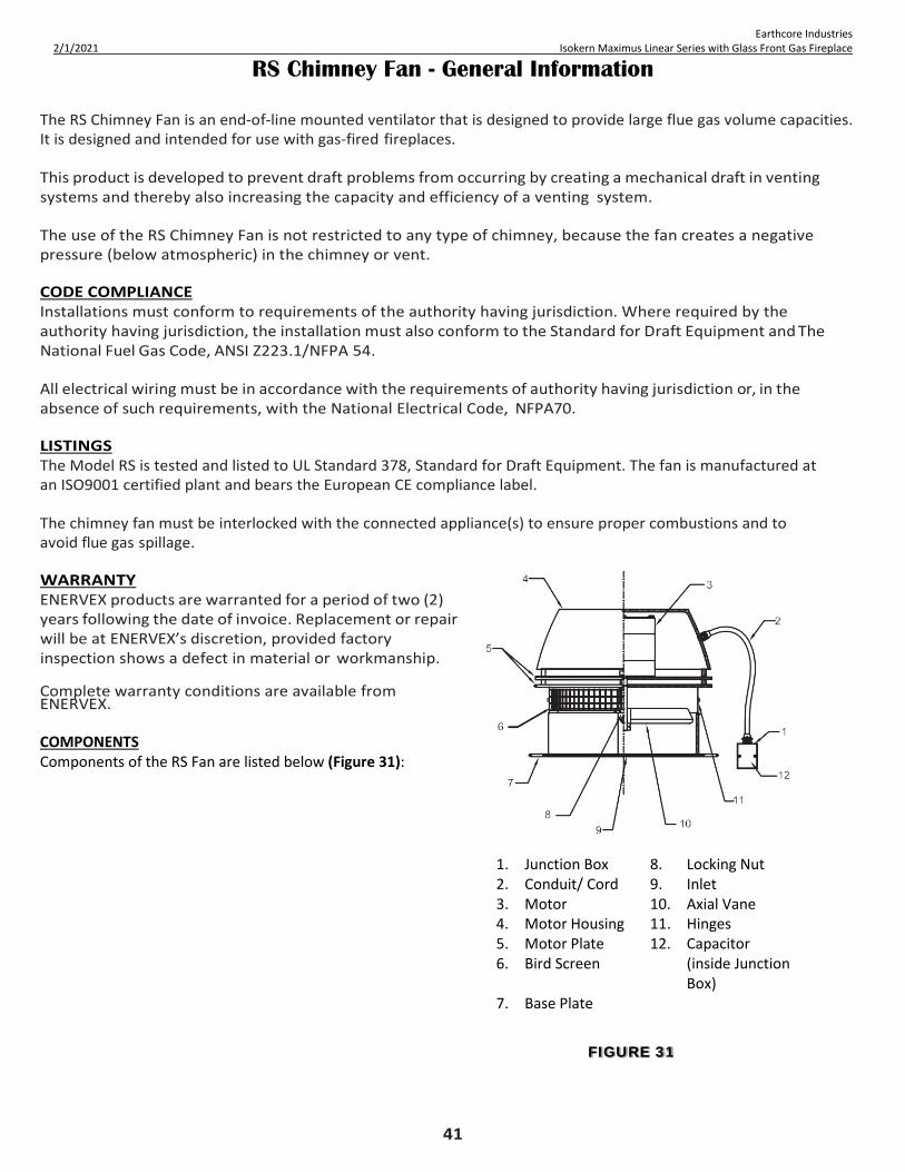
RS Chimney Fan - General Information
The RS Chimney Fan is an end-of-line mounted ventilator that is designed to provide large flue gas volume capacities. It is designed and intended for use with gas-fired fireplaces. This product is developed to prevent draft problems from occurring by creating a mechanical draft in venting systems and thereby also increasing the capacity and efficiency of a venting system. The use of the RS Chimney Fan is not restricted to any type of chimney, because the fan creates a negative pressure (below atmospheric) in the chimney or vent. CODE COMPLIANCE Installations must conform to requirements of the authority having jurisdiction. Where required by the authority having jurisdiction, the installation must also conform to the Standard for Draft Equipment and The National Fuel Gas Code, ANSI Z223.1/NFPA 54. All electrical wiring must be in accordance with the requirements of authority having jurisdiction or, in the absence of such requirements, with the National Electrical Code, NFPA70. LISTINGS The Model RS is tested and listed to UL Standard 378, Standard for Draft Equipment. The fan is manufactured at an ISO9001 certified plant and bears the European CE compliance label. The chimney fan must be interlocked with the connected appliance(s) to ensure proper combustions and to avoid flue gas spillage. WARRANTY ENERVEX products are warranted for a period of two (2) years following the date of invoice. Replacement or repair will be at ENERVEX’s discretion, provided factory inspection shows a defect in material or workmanship. Complete warranty conditions are available from ENERVEX.
COMPONENTS Components of the RS Fan are listed below (Figure 31):
1. Junction Box 8. Locking Nut 2. Conduit/ Cord 9. Inlet 3. Motor 10. Axial Vane 4. Motor Housing 11. Hinges 5. Motor Plate 12. Capacitor 6. Bird Screen (inside Junction
Box) 7. Base Plate
FIGURE 31

42
Earthcore Industries 2/1/2021 Isokern Maximus Linear Series with Glass Front Gas Fireplace
FIGURE 32
MFD– Vertical Termination Installation 1) Before installing the MFD on the chimney, a power cable should be wired to the actuator and the actuator cover
should be secured (Figure 32). 2) Use 4-conductor cable (min. 18 AWG) with a weatherproof jacket such as rubber or silicone. Install a
weatherproof cable connector on the side of the actuator cover to prevent water ingress to the actuator.
3) Use (6) of the included sheet metal screws to secure the actuator cover to the MFD. Once secure, apply a bead of silicone around the seams of the cover.
4) Mount the MFD outdoors at the top of a steel chimney. Slide the collar of the MFD into the steel chimney until the
damper rests on the stop flange. Sheet metal screws may be installed around the collar into the chimney for additional support (Figure 33).
FIGURE 33

43
Earthcore Industries 2/1/2021 Isokern Maximus Linear Series with Glass Front Gas Fireplace
RS Fan Vertical Termination Installation Support system for the chimney fan Prior to installation of the chimney fan, it must be assured the chimney can safely carry the weight of the chimney fan. A steel chimney should be well supported at the roof penetration point. If the chimney extends more than 20' above the roof, the chimney and the fan should be secured by wires attached on the chimney and on the roof at 2 to 3 different points. Brick chimneys usually do not need any kind of support to carry the weight of the chimney fan. TRANSPORT SAFETY DEVICE If a transport safety device is present, remove it from the vane and make sure that the vane can revolve without hindrance. RS 12/14: Before mounting, the transport safety device on the hinges must be removed. Fan Installation – Vertical Termination
5. Measure the inside diameter of the flue and cut a corresponding
hole in the center of the fiber mat. If the flue is so big that the throat in the adapter has been reduced to fit the throat of the fan, the hole in the fiber mat should correspond to the throat.
6. The aluminum foil on the fiber mat must face upward
(against fan base).
7. The chimney fan is now ready for installation on the top of the chimney. Place the fiber mat with the aluminum foil facing upwards on the top of the MFD and place the fan on top of the mat. High temperature silicone can be applied on the side of the mat but is not required. It can also be painted Use the mounting holes on the fan base as a drill template to make one mounting holes in each corner of the adapter. Use bolts and locking nuts to secure the fan to the MFD. (Figure 34)
WARNING!!!: Under conditions with extremely strong winds surrounding the top of the chimney, the chimney fan must be secured by steel wires supplied with the fan.
FIGURE 34

44
Earthcore Industries 2/1/2021 Isokern Maximus Linear Series with Glass Front Gas Fireplace
MFD – Horizontal Termination Installation
1. Before installing the MFD on the chimney, a power cable should be wired to the actuator and the actuator cover should be secured (Figure 35).
2. Use 4-conductor cable (min. 18 AWG) with a weatherproof jacket such as rubber or silicone. Install a weatherproof cable connector on the side of the actuator cover to prevent water ingress to the actuator.
3. Use (6) of the included sheet metal screws to secure the actuator cover to the MFD. Once secure, apply a bead of silicone around the seams of the cover.
4. Mount the MFD outdoors at the end of a steel chimney. Slide the collar of the MFD into the steel chimney until the damper rests on the stop flange. Sheet metal screws may be installed around the collar into the chimney for additional support. Fasten the MFD to noncombustible framing with metal fasteners or bolts with locking nuts (Figure 36). NOTE: An 18” clearance to combustible is required for the MFD.
FIGURE 35 FIGURE 36

45
Earthcore Industries 2/1/2021 Isokern Maximus Linear Series with Glass Front Gas Fireplace
RS Chimney Fan – Horizontal Termination Installation
5. To ease installation, detach the fan base by removing the bolts holding the hinges together. Center the fan base over the outlet and bolt the base onto the wall with the hinges pointing upwards (Figure 37).
6. After mounting the base securely, attach the fan motor
housing by reassembling the fan hinges. Seal with silicone all around the fiber mat to prevent rain from entering the flue.
7. To achieve optimal performance and energy consumption
for the RS Fan, the duct must be installed as shown below and the distances observed. From the last elbow to the termination point the distance must be 4 times the diameter of the flue. For example, if you use 12in flue, the distance from the last elbow to the fan termination point should be 48 inches (12 X 4 = 48in) (Figure 38).
8. A venting system that terminates in the sidewall of a
structure shall terminate at least 3 ft (0.9 m) above any air inlet to the structure that is within 10 ft (3 m) of the termination point.
Exception: This requirement shall not apply to the separation distance between the circulating air inlet and the vent discharge of a listed outdoor appliance.
NOTE: The flue gas outlet of this appliance shall terminate at
least 4 ft (1.2 m) below, 4 ft (1.2 m) horizontally from, or 1 ft (0.3 m) above any door, window, or gravity air inlet of the structure. The outlet also shall terminate at least 1 ft (0.3 m) above grade.
9. ADC100 must be interlocked with the appliance(s). The
safety system will utilize a Proven Draft Switch, PDS. The PDS device must be interlocked with the heating appliance so that it shuts down in case of insufficient draft, fan failure, or power failure.
10. The Figure 39 shows the location of the probe for the PDS.
Location is important to make sure there is enough pressure or draft available or the switch to work.
IMPORTANT: Framing and sheathing at horizontal termination shall require non-combustible material within the 18” clearance zone as measured from outer diameter of MFD collar.
FIGURE 37
FIGURE 38
FIGURE 39

46
Earthcore Industries 2/1/2021 Isokern Maximus Linear Series with Glass Front Gas Fireplace
Complete Electrical Schematic
FIGURE 40

47
Earthcore Industries 2/1/2021 Isokern Maximus Linear Series with Glass Front Gas Fireplace
Enervex ADC 100 Connection Diagram Connection Diagram
Overall Connection Diagram Notes • Power supply shall be from building source power on a dedicated circuit • RS fan wiring shall be dedicated for the fan; branching of the circuit will cause erratic fan behavior • RS Fan and Mechanical Fireplace Damper may be installed in a vertical mount above the roof or in a horizontal
mount on an outside wall • Junction / capacitor box will be mounted near the fan mount • Fan circuit disconnect de-energizes the fan circuit for the purpose of servicing - recommended installed by the
manufacturer – must meet local code requirements; not supplied • Fan speed control switch is installed for the purpose of fan speed initial set up; should be mounted in a location
that is not accessible to the general public. • MFD wiring details – page 48 • RS fan circuit wiring details – page 48 • Proven draft switch wiring details - page 49 • Fireplace wiring details – page 59
FIGURE 41

48
Earthcore Industries 2/1/2021 Isokern Maximus Linear Series with Glass Front Gas Fireplace
FIGURE 42
FIGURE 43
MFD Wiring Wire the actuator for 2 wire/ 2 position operation as shown in Figure 42 (120 VAC) and Figure 43 below. The actuator should be set for clockwise (CW) rotation and should fail to 90 degrees (MFD will open). Verify settings of the actuator before wiring.
Damper Actuator Wiring Notes
The damper actuator will have a cord with 2 wires- black insulation wire and white insulation wire. This chord supplies power for damper open / close operation
• The black insulation wire is L1 power -connect to terminal 15 of ADC 100
• The white insulation wire is Neutral – DOES NOT CONNECT TO ADC 100 - must connect to any neutral wire that traces back to the circuit breaker box neutral bus bar
The damper actuator will have a cord with 3 wires. These wires provide an electrical signal that indicates the damper position open / close
• purple insulation labeled S1 will connect to terminal 16 of ADC 100 • red insulation wire labeled S2 NOT USED, cap this wire • white insulation wire labeled S3 will connect to terminal 17 of ADC 100
RS FAN Wiring All electrical wiring must be in compliance with the local codes or in their absence, with the National Electric Code, NFPA 70 — latest edition. If an external electrical source is utilized, system must be electrically grounded in accordance with requirements of the authority having jurisdiction or, in the absence of such requirements, with the National Electrical Code NFPA 70 — latest edition. Power requirements for the system depends on the fan size. Electrical requirements are:
• RSHT012 1 x 120 V/60 Hz 1.2 Amps • RSHT014 1 x 120 V/60 Hz 1.4 Amps
The chimney fans have a split capacitor motor with infinitely variable speed. The fan speed control supplied is rated 1 x 120 V/60 Hz and 5 Amps. It has an adjustable low voltage set point of min. 65 V +/- 5 V. (Figure 44)
RS Fan Wiring Notes
• N - white insulated wire connects terminal 5 of ADC 100 positive side of capacitor, black insulation wire (in capacitor box) and white wire from fan motor (in capacitor box)
• L1 - black insulated wire connects terminal 4 of ADC 100 to A terminal of Fan Speed Control rheostat switch
• B terminal of Fan Speed Control rheostat connects to black insulated wire from fan (in capacitor box)
If any of the original wire supplied with the
! insulation may melt or degrade, exposing bare
system must be replaced, use similar wire of the same temperature rating. Otherwise,
wire.
FIGURE 44

49
Earthcore Industries 2/1/2021 Isokern Maximus Linear Series with Glass Front Gas Fireplace
FIGURE 44
FIGURE 45
Enervex ADC 100 Installation
1. The ADC100 Control Unit must be installed indoors. As shown in Figure 45, the control will be wired directly to a 120/1/60 VAC power supply. The control will also be connected to the fan, appliance, and damper
2. The ADC100 control may be mounted directly to a wall. To mount, remove the cover and locate the (4) mounting holes. Using the hole-pattern shown in Figure 46, mount the control using #6 screws.
3. The Proven Draft Switch (PDS) must be installed indoors, in the vertical position (pre-drilled knockouts face down). Mount the control upright to a wall or other flat surface. DO NOT lay the control down or mount horizontally
4. A Proven Draft Switch (PDS) must be used with the ADC100 control as a system safety device. The PDS monitors the pressure inside the stack and signals the control to shut down the appliance if insufficient draft exists. A stack probe senses the pressure read by the PDS and is connected via silicone tubing. The silicone tubing supplied with the PDS should be connected to the NEGATIVE (-) port of the PDS. This is the bottom port on the switch. See Figure 47. The standard tube length is 6 feet. The distance can be extended up to 25 feet by using 1/4" rigid plastic or copper tubing as temperature allows (not supplied).
Proven Draft Switch Notes
Proven Draft Switch is a diaphragm switch that closes when pressure is applied to the diaphragm.
• purple insulation wire is C, common, connect to terminal 13 on ADC 100 • gray insulation wire is NC, normally closed;
connect to terminal 12 on ADC 100 • white insulation wire is NO, normally open;
connect to terminal 11 on ADC 100
FIGURE 47
FIGURE 46

50
Earthcore Industries 2/1/2021 Isokern Maximus Linear Series with Glass Front Gas Fireplace
Enervex ADC 100 Installation
5. The probe must be installed between the
appliance and the exhaust fan. If a damper is used in the system, the probe should be installed between the appliance and damper. The probe needs to be at least 3’ from the last elbow in the vent run.
6. For fireplace installations, the probe should be installed close to the fan inlet. See Figure 48.
7. To produce an accurate pressure reading, the probe should be installed flush with the inner wall of the chimney or stack. If double walled stack is used, the probe should be flush with the inner most wall.
Fan Speed Control 8. Locate the FSC in close proximity to the burner valve
control system but only in a location accessible to service technician.
Connect the FSC control switch as shown in Figure 49.
9. The FSC will be utilized for the initialization set up, see page 71.
NOTE: After the installation is complete, perform a functional check.
FIGURE 49
FIGURE 48

51
Earthcore Industries 2/1/2021 Isokern Maximus Linear Series with Glass Front Gas Fireplace
Enervex ADC 100 Installation
ADC 100 Terminal Designation The designations for each terminal on the control board are shown below. Note that Figure 50 only shows the terminals relevant to the Maximus Linear installation. Also shown in this section is a general connection diagram for an ADC100 control system.
.
1 Line Power – L1 11 Proven Draft Switch NO; white
2 Line Neutral 12 Proven Draft Switch NC; gray
3 Ground 13 Proven Draft Switch C; purple
4 Fan Power to FSC 14 Line Power – L1 from junction box
5 Fan Neutral 15 Damper Power cord L
6 Fan Ground 16 Damper – actuator cord S1 NC; purple
7 Wall Switch 17 Damper – actuator cord S3 NO; white
8 Jump to terminal 10 22 Terminal X4 on Proflame Module
9 Wall switch 23 Terminal X4 on Proflame Module
10 Jumper to terminal 8 NOTE Damper power cord N must connect to junction box neutral
FIGURE 50

52
Earthcore Industries 2/1/2021 Isokern Maximus Linear Series with Glass Front Gas Fireplace
Firebrick Installation - General Information
Earthcore/ Isokern requires the Maximus Linear Series fireboxes be lined with a minimum one and one-eighth (1-1/8”) thick firebrick (“Split”) for the sidewalls and 2-1/4” thick firebrick (“Full”) on the floor. Thicker firebrick may be used as an option. The pattern for the firebrick lining is an owner option. The ISOSET mortar by Earthcore is to be used when lining the Isokern Fireplace. ISOSET FIREBRICK MORTAR APPLICATION: • Add .75 quarts of water per 10 lbs. of dry product until completely blended. • Only mix what can be utilized within 15 minutes. • Do not re-temper (the addition of water after the chemical reaction has begun). • The use of warm water will accelerate setup. • Joint thickness should be thin (1/4”- 3/8”) • Complete set time is between 48 and 72 hours. • For best results, please allow 28 days before heat is applied. • Approximately 35 to 40 lbs. of prepared mortar will lay up one hundred 9” x 4 ½” x 2 ½” straights. IMPORTANT!!!: DO NOT add additives, such as fire-clay, sand, cement, or other accelerators. These instructions may vary because of different climates and conditions. The use of good masonry practices for your area should also be considered.
FOR BEST RESULTS: • Wet mop the inside of the fireplace with a damp sponge to remove dust and loose particles from the interior before
installing firebrick. Keep the fireplace damp while installing firebrick. • After wetting sponged interior of firebox, apply a 1/4 notch bed joint on rear sides and floor. • Dip each firebrick in a pale of water before applying mortar to one side for adherence to firebox. • Facing joint dimensions of ¼” to 3/8” in the brick work are recommended and have the best appearance. Other face
joint dimensions are acceptable, however smaller joints may not leave room for heat expansion of firebrick.
NOTE: Earthcore makes no claims as to the performance of firebrick or firebrick mortar(s). It is typical for heat stress cracks to appear in the firebrick in fireplaces.

53
Earthcore Industries 2/1/2021 Isokern Maximus Linear Series with Glass Front Gas Fireplace
Firebrick Installation - Maximus Linear Fireplace
1. Starting approximately 1/2” from the rear of the firebox, lay one course of “full” sized firebrick. Ensure a gap of approximately 1/2” is kept between firebrick and sidewall to allow for expansion.
2. Next, two courses of “full” sized firebrick shall start at the leading edge of the baseplate. Ensure a gap of approximately 1/2” is kept between firebrick and sidewall to allow for expansion.
NOTE: the leading edge of firebrick may be installed atop the Air-Collector Box but SHALL NOT block the Cooling-Air Vents.
3. Apply “split” firebrick to the rear wall of the unit.
Ensure approximately 1/2” gap is kept between firebrick and sidewall, as well as an 1/4” gap is kept between firebrick and damper beam assembly to allow for expansion.
4. Repeat on opposite side wall. IMPORTANT: Ensure that the required holes for the Isoflames Linear burner’s 3/8” gas supply and pilot assembly gas and electrical connections are drilled prior to firebrick installation. DO NOT COVER THESE AREAS WITH FIREBRICK!
FIGURE 51
FIGURE 52
NOTE: Gas and electrical connections may be brought through the rear wall of the unit and into the area of the firebrick cavity. A gap will need to be left in the firebrick extending from the cavity to the rear wall of the unit for passage of the 3/8” gas line, pilot tube, and electrical connections. Ensure all holes are filled with mortar after installation.

54
Earthcore Industries 2/1/2021 Isokern Maximus Linear Series with Glass Front Gas Fireplace
FIGURE 53
FIGURE 54
Flush Wall Finish Detail
Maximus Linear units shall be installed so that the rough front faces of the Isokern firebox are flush to the outside edges (room side) of the rough framing members that create the room wall’s finish (Figure 53).
IMPORTANT!!!: Do not build a combustible frame wall in front of the Maximus Linear Fireboxes (Figure 54). CLEARANCE TO DRYWALL Drywall can be placed directly in contact with the front of the Maximus Linear smoke dome. Drywall can be hung on the framing members and pass across the face of the Maximus Linear smoke dome and in contact with it.
This sheathing can be installed at zero-clearance to the firebox opening on the Maximus Linear with Glass Front. IMPORTANT: Any gaps or voids that result from the installation of material installed against the fireplace must be filled with Earthcore adhesive.
WARNING!!!: Avoid false chimneys. Failure to seal any gaps between the front face(s) of the firebox and the back of the noncombustible finished facing material will create what is known as a “false chimney” or “secondary chimney”. A “false chimney”, in this case is the narrow gap between the back of the facing material at the top of the firebox opening and the rough front of the Maximus Linear damper assembly/ smoke dome. If left unfilled this gap creates a “false-chimney” which can cause a fire hazard by drawing considerable heat out of the firebox and into the space behind the noncombustible finish facing and then up into the wall cavity behind the drywall or other sheathing material that houses the Isokern fireplace

55
Earthcore Industries 2/1/2021 Isokern Maximus Linear Series with Glass Front Gas Fireplace
FIGURE 55
FIGURE 56
Clearance to Combustible Trim
NOTE: “Clearance to Combustible Trim” are those distances required to ensure that a fireplace mantel or facing will not catch fire. In most cases the distances should also be adequate to prevent any discoloration or warping due to heat. However, each installation presents a unique and completely different set of circumstances involving many variables.
These variables include paint or finish composition, previous exposure to heat, methods and quality of construction, air flow patterns, etc. Because of these variables, the manufacturer does not guarantee that heat-warping or discoloration will never occur.
MANTEL AND MANTEL SHELF CLEARANCES: Maximus Linear with Glass Fronts units are designed to be installed so that the rough front face(s) of the Isokern firebox and sits flush with the face of the rough framing members that create the room wall finish. The Maximus Linear with Glass Front has been tested to zero-clearance to combustible mantel and sheathing. Prior to installation, verify that additional clearances are not required by local code (Figure 55).
Adjoining Walls: It is recommended that adjoining room walls to the Isokern fireplace installation not be closer than twenty-four inches (24”) to the finished fireplace opening (Figure 56).
Ceilings:
The minimum clearance from the top of the fireplace opening to a ceiling is forty-two inches (42”) (Figure 57).
FIGURE 57

56
Earthcore Industries 2/1/2021 Isokern Maximus Linear Series with Glass Front Gas Fireplace
Isoflames Linear Burner - Safety Instructions
WARNING!!!: This appliance assembly contains burner orifices specifically for the input gas specified on the burner and box, as well as the BTU rating specified in this manual. Modifying or failure to use the factory orifice may cause property damage, personal injury, or loss of life. Read these instructions completely before installing and using ISOFLAMES Linear Burner 1) This Maximus Linear Series fireplaces must utilize the Isoflames Linear Burner that is specified for the particular fireplace
model. 2) The Maximus Linear Series fireplaces utilize a mechanical draft system that interlocks with the Isoflames Linear burner to
ensure burner operation is only possible when the mechanical draft system is energized, and safe operation is proved by the control. This ensures all carbon monoxide and other flue gases will be expelled through chimney system.
3) Solid fuels shall not be burned in the Maximus Linear Series fireplaces, or any fireplace where a decorative appliance has
been installed. 4) The minimum inlet supply pressure for the purpose of input adjustment is 5.0 inches (natural gas) 11.0 inches (propane) in
water column. The maximum inlet supply pressure is 10.5 inches (natural gas) 13.0 inches (propane) in water column. 5) Gas type will be indicated on the burner rating plate. Do not use a natural gas burner with propane or a propane burner with
natural gas. Appliance is not convertible to use other gases. 6) The installation, provisions for combustion, and ventilation air must conform to the National Fuel Gas Code, ANSI Z223.1/
NFPA 54, or the Natural Gas and Propane Installation code, CSA B149.1. 7) The appliance and its main gas valve must be disconnected from the gas supply piping system during any pressure testing of
that system at test pressures in excess of 1/2 psi (3.5 kPa). The appliance must be isolated from the gas piping system by closing its equipment shutoff valve during any pressure testing of the supply piping system at test pressures equal to or less than 1/2 psi (3.5 kPa).
8) Do not use this appliance if any part has been under water. Immediately call a qualified service technician to inspect the
appliance and to replace any part of the control system and any gas control which has been under water. 9) Periodic examination and cleaning of the venting system of the solid fuel burning fireplace, including frequency of such
examination and cleaning, by a qualified agency. 10) The appliance area is to be clear and free from combustible materials, gasoline and or flammable vapors and liquids. For
warranty to be valid gas log sets must be installed by a NFI certified or other qualified professional installer. 11) Always check local building codes governing fireplaces and fireplace installations. ISOFLAMES Linear Burner installation
must comply with all local, regional, state, and national codes and regulations. 12) This appliance is only for use with the type of gas indicated on the rating plate. This appliance SHALL NOT be field
converted for use with other gases with Propane (LP) or Natural Gas (NG). 13) This appliance shall only be installed, serviced, or inspected by qualified professional service technician.
14) For propane (LP) use do not place propane supply tank(s) inside any structure. Locate propane supply tank(s) outdoors. 15) To prevent performance problems, do not use propane fuel tank of less than 100 lbs. capacity. 16) This decorative gas appliance reaches high temperature. Keep children and adults away from hot surfaces to avoid burns or
clothing ignition. Fireplace will remain hot for a time after shutdown. Allow surfaces to cool before touching. 17) Turn the appliance off and allow to cool before servicing. Always shut off any electricity and gas to the appliance while
working on it. Only a qualified service person should install, service or repair this appliance. Have your appliance inspected annually by a qualified service person.

57
Earthcore Industries 2/1/2021 Isokern Maximus Linear Series with Glass Front Gas Fireplace
Isoflames Linear Burner - Safety Instructions
18) It is imperative that the unit’s control areas, burners and circulation air passages be kept clean. 19) Keep all combustible material, gasoline, and other flammable liquids at a safe distance from the fireplace. Do not use the
appliance where these items are used or stored. Decorations, clothing, and other such combustible items should not be placed on the appliance.
20) Do not cook food or burn paper or other object(s). 21) Do not use any solid fuels - wood, coal, paper, cardboard, etc. - Use only the gas type listed on the fireplace’s burner rating
plate. 22) Do not in any way obstruct the flow of combustion and ventilation air. Provide adequate clearances around air openings into
the combustion chamber as well as adequate accessibility clearances for servicing and proper operation. 23) Never install an ISOFLAMES Linear Burner component or accessory that has visible or suspected physical damage. These
items should be inspected by a qualified representative to ensure safe condition. When in doubt, consult your local supplier. 24) Do not alter or modify the ISOFLAMES Linear Burner or burner components under any circumstances. Modification or
alteration of any sort may void manufacturer’s warranty, listings, and approvals. 25) The ISOFLAMES Linear Burner system is not intended to heat an entire home or to be used as a primary heat source. 26) Children and adults should be alerted to the hazards of high surface temperature and should stay away from this appliance to
avoid burns or clothing ignition. 27) Young children should be carefully supervised when they are in the same room as the appliance. Toddlers, young children,
and others may be susceptible to accidental contact burns. A physical barrier is recommended if there are at-risk individuals in the house. To restrict access to the fireplace, install a adjustable safety gate to keep toddlers, young children and other at-risk individuals out of the room and away from hot surfaces.
28) Clothing or flammable material should not be placed on or near the appliance. 29) Due to high temperatures, the appliance should be located out of traffic and away from furniture and draperies. 30) Any safety screen, guard, or barrier removed for servicing an appliance must be replaced prior to operating the appliance. 31) Installation and repair should be done by a qualified service person. The appliance should be inspected before use and at
least annually by a professional service person. More frequent cleaning may be required due to excessive lint from carpeting, bedding material, etcetera. It is imperative that control compartments, burners, and circulating air passageways of the appliance be kept clean.

58
Earthcore Industries 2/1/2021 Isokern Maximus Linear Series with Glass Front Gas Fireplace
Isoflames Linear Burner - Safety Instructions WARNING!!!: This product contains or generates chemicals known to the state of California to cause cancer or birth defects or other reproductive harm. IMPORTANT: Read this owner’s manual carefully and completely before trying to assemble, operate or service this fireplace. Improper use of this fireplace can cause serious injury or death from fire, burns, explosions, and carbon monoxide poisoning. DANGER!!!: CARBON MONOXIDE POISONING MAY LEAD TO DEATH! Propane (LP) gas and natural gas (NG) are both colorless and odorless gases. An odor making agent is added to each of these gases to help you detect a gas leak. However, the odor added to these gases can fade and gas may be present even though no odor exists. Carbon Monoxide Poisoning: Early signs of carbon monoxide poisoning resemble flu symptoms, including headaches, dizziness or nausea. If you have these signs the fireplace may not have been installed properly, get fresh air at once! Have the fireplace inspected and serviced by a qualified service person or your gas supplier. Some people are more affected by carbon monoxide than others. These include pregnant women, people with heart or lung diseases or anemia, people at high altitude or under the influence of alcohol. Earthcore Industries strongly recommends the use of a carbon monoxide detector/alarm device wherever gas fired appliances are in use. All parties either involved in or associated with the installation, service and use of this fireplace must read this entire manual. Keep this manual for reference and as a guidebook to safe operation of this fireplace. WARNING!!!: This unit is not for use with solid fuel.
Isoflames Linear Burner - Rating Plate
Natural Gas Propane

59
Earthcore Industries 2/1/2021 Isokern Maximus Linear Series with Glass Front Gas Fireplace
Isoflames Linear Burner - Components List `
NOTE: burner segment shown
③ Top view
Bottom view
TABLE 2
Item No. Description Part No.
Qty
1 Main Burner Assembly (natural gas) Main Burner Assembly (propane)
ISF-E-36/60/72/96N ISF-E-36/60/72/96P
1 1
2 Pilot Assembly (natural gas) Pilot Assembly (propane)
ISF-E-PAN ISF-E-PAP
1 1
3 Gas Valve (natural gas) Gas Valve (propane)
ISF-E-GVN ISF-E-GVP
1 1
4 Control module/remote receiver ISF-E-CM 1 5 Battery Holder/Switch ISF-E-BH 1 6 Remote Transmitter ISF-E-RM 1 7 1/2" Flared fitting female adapter ISF-E-FFA1 1 8 3/8" Flared fitting female adapter ISF-E-FFA2 1 9 Wall Plate Cover E-EWC 1
⑨
④
①

60
Earthcore Industries 2/1/2021 Isokern Maximus Linear Series with Glass Front Gas Fireplace
Isoflames Linear Burner - Specifications
TABLE 3
Burner Specifications
Burner Model
Minimum Fireplace Dimension (in) BTU
Depth Height Width Nat. Gas L.P. Gas Front Rear High Low High Low
ISF36LB 17.5 16 48 37 54K 38K 48K 36K ISF60LB 17.5 16 72 61 90K 63K 80K 60K ISF72LB 17.5 16 84 73 108K 75K 96K 72K ISF96LB 17.5 16 108 97 108K 84K 105K 87K
NOTE: Height is measured from hearth floor to bottom of lintel

61
Earthcore Industries 2/1/2021 Isokern Maximus Linear Series with Glass Front Gas Fireplace
FIGURE 58
Gas Line & Valve Box Installation
This appliance must be connected to the gas line in accordance with local codes and/or the National Fuel Gas Code, ANSI Z223.1. After connecting the gas line, all joints in the line and connections at the valve should be checked for leaks before final positioning of the unit. Conduct a gas leakage test of the appliance piping and control system downstream of the shutoff valve in the supply line to the appliance.
1) The valve control box comes with an 84” pilot assembly lead; therefore, the box must be mounted within 5’ of the fireplace for models ISF36/60LB and within 1’ for models ISF72/96LB. (Figure 58)
2) Attach the metal enclosure to the studs using standard building materials. The metal enclosure must be mounted in a location that can be accessed in the future for additional connections & future servicing.
3) Installation and servicing of gas appliances and ignition systems must only be performed by qualified personnel.
4) Turn off gas and electricity before starting installation or service.
5) Make sure gas piping is pressure tested before control is connected. High pressure can damage the control causing a hazardous condition.
6) Make sure piping is clean and free from burrs. Apply a small amount of good quality gas-rated pipe thread compound or plumbers’ tape suitable for the gas being used. Thread compound should be used sparingly on male threads only, leaving the first two threads clean.
7) It is recommended that a safety shut off valve is installed on either the gas in or gas outside of the valve.
8) It is recommended to hard pipe in the connections with unions installed inside the box.
9) Uncoil the pilot assembly. Be careful to not create unwanted kinks in the pilot tubing.
10) Feed the spade connector ends of the pilot assembly from inside the fireplace to the outside being careful not to clog the flared fitting of the pilot tube or damage the spade connectors.
11) Plug the spade connectors into the module according to the below wiring diagram (Figure 59 & 60), insert the pilot tubing into the right side of the valve and using a wrench, tighten the nut so that the pilot tubing cannot be pulled out.
2
4
3

62
Earthcore Industries 2/1/2021 Isokern Maximus Linear Series with Glass Front Gas Fireplace
FIGURE 35
FIGURE 60
FIGURE 59
Valve Box & Burner Wiring Diagram
WARNING!!!: Do not connect 120 VAC to the control valve.
The appliance and its appliance main gas valve must be disconnected from the gas supply piping system during and pressure testing of that system at test pressures in excess of 1/2 psi (3.5 kPa).
The appliance, when installed, must be electrically grounded in accordance with local codes or in the absence of local codes, with the National Electrical Code, ANSI/NFPA 70. If not installed and maintained in accordance with the manufacturer’s instructions, this product could expose you to substances in fuel or fuel combustion which are known to the state of California to cause cancer, birth defects or other reproductive harm.
For a copy of the homeowner’s care and operation manual, go to www.earthcore.com or call 1-800-642-2920.
Green Wire (from DFC wire harness)
Inlet (IN) Test Port
Manifold (OUT) Test Port
Orange Wire (from DFC wire harness)
Hi/Lo Flame Control Knob
Main Gas Inlet 3/8” NPT
Yellow Ground Wire (from DFC wire harness)
TABLE 4

63
Earthcore Industries 2/1/2021 Isokern Maximus Linear Series with Glass Front Gas Fireplace
FIGURE 61 FIGURE 62
TABLE 5
Burner Installation
IMPORTANT: Prior to installation: Shut off main gas supply to fireplace.
1) The ISOFLAMES Linear Burner system shall be installed by qualified professional service technician. To ensure proper performance of the appliance the owner’s installation manual must be followed carefully.
2) When used in the Maximus Linear Fireplace with Glass Front, the ISOFLAMES Linear Burner is designed to be recessed
into the 2-1/2” deep firebrick cavity constructed as detailed in the Firebrick Installation portion of this manual (pgs. 52-53/ Figure 61 & 62).
3) The burner cavity must have a height of 2-1/2”, a minimum depth of approximately 7-1/4”, and the length shall extend the entire width of
firebox. 4) The 48” and 72” Maximus Linear fireplaces (82L48 & 82L72) will require the ISF36/60LB (respectively): Gas supply piping for these
models shall terminate not less than 3” from sidewall. (Figure 63) 5) The 96” and 120” Maximus Linear fireplaces (82L96 & 82L120) will require the ISF72/96LB (respectively): Gas supply stub piping for
these models shall terminate within 3” from center of the cavity. (Figure 63)
BURNER CAVITY DIMENSIONS (in) Burner Model Height Width Length
ISF36LB 2-1/2 6-13/16 to 7-1/4 FULL ISF60LB 2-1/2 6-13/16 to 7-1/4 FULL ISF72LB 2-1/2 6-13/16 to 7-1/4 FULL ISF96LB 2-1/2 6-13/16 to 7-1/4 FULL

64
Earthcore Industries 2/1/2021 Isokern Maximus Linear Series with Glass Front Gas Fireplace
FIGURE 63
Burner Installation
1) Connect all burner segments according to burner model diagram page 65-67. Make sure all connections are tightly secured.
2) Place burner assembly in center of fireplace floor or cavity.
3) Rotate the burner to position the gas inlet fitting on burner closest to the gas-supply stub coming from the gas valve. (Not necessary for models ISF72/96LB)
4) Remove the burner top closest to the gas-supply stub. Remove the top pan by unscrewing the two screws. This will allow easier access and connection of flex connector to the flared fitting. This will also be used for pilot assembly installation
5) Connect the appropriate 3/8” flared fitting is connected to the gas supply stub.
6) Connect the 12” flex connector to the gas inlet flared fitting on the burner assembly.
7) Connect the other end of 12” flex connector to the gas-supply.
8) Avoid creating kinks in the flex connector.
9) Make sure all connections are tightly secured.
10) Before replacing the removed burner top from Step 4, locate the perforated rectangular section in the pan. Gently remove this section along the perforations using a screwdriver or pliers (Figure 64).
11) Insert the pilot assembly from underneath the existing burner pan to the area of the removed burner section (Figure 65).
12) Mount the pilot assembly to the removed burner pan using the screws provided with the pilot assembly. Be careful not to kink the pilot assembly tube as it can severely damage the pilot tube (Figure 66).
13) Place the removed burner top back on to the orifice block and secure tightly with the pan head screws.
FIGURE 64
FIGURE 65
FIGURE 66

65
Earthcore Industries 2/1/2021 Isokern Maximus Linear Series with Glass Front Gas Fireplace
36” Burner Connection - ISF36LB For Isokern Maximus Linear 82L48
60” Burner Connection – ISF60LB For Isokern Maximus Linear 82L72
ISF36LB
Box No. Part No. Qty.
4 E-18BP4 1
8 E-12BP1 1
ISF60LB
Box No. Part No. Qty.
1 E-18BP1 1
4 E-18BP4 1
6 E-18BP6 1
4 6
1
4
8

66
Earthcore Industries 2/1/2021 Isokern Maximus Linear Series with Glass Front Gas Fireplace
72” Burner Connection – ISF72LB For Isokern Maximus Linear 82L96
ISF72LB
Box No. Part No. Qty.
4 E-18BP4 1
5 E-18BP5 1
9 E-12BP2 1
10 E-12BP3 1
13 E-BPC 1
5
10
13
9
4
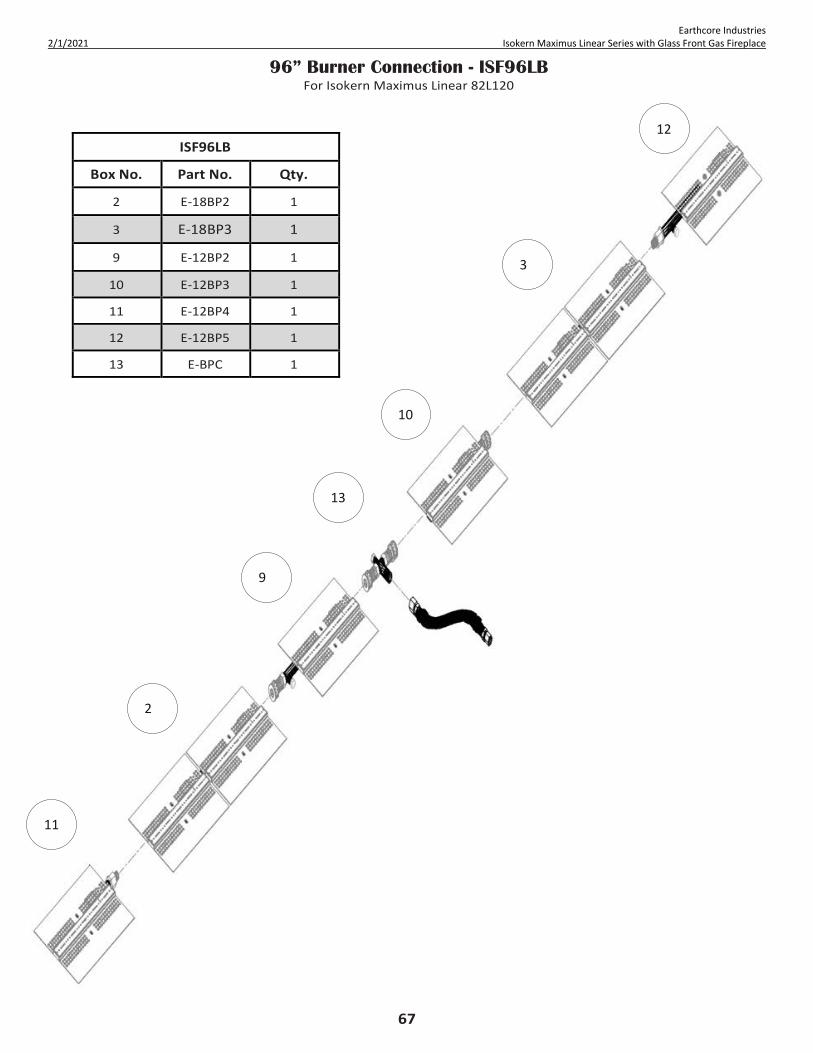
67
Earthcore Industries 2/1/2021 Isokern Maximus Linear Series with Glass Front Gas Fireplace
96” Burner Connection - ISF96LB For Isokern Maximus Linear 82L120
ISF96LB
Box No. Part No. Qty.
2 E-18BP2 1
3 E-18BP3 1
9 E-12BP2 1
10 E-12BP3 1
11 E-12BP4 1
12 E-12BP5 1
13 E-BPC 1
13
3
10
9
2
11
12

68
Earthcore Industries 2/1/2021 Isokern Maximus Linear Series with Glass Front Gas Fireplace
Burner Lighting Instructions INSTALLER INSTRUCTIONS It is required that the set of safety instruction labels that have been supplied with the appliance be affixed to the operation and control points of the appliance. It is the installers responsibility to ensure these warnings are properly affixed during installation. These warning labels are a critical step in informing consumers of safe operation of this appliance.
PRE-LIGHTING CHECKLIST Be sure to check these items before the initial
lighting of the appliance: • Gas pressure has been checked carefully • All gas fittings have been checked for leaks. • All clearances to combustibles have been met • All combustibles materials have been removed
from the area in front of the appliance. • All vented areas of the appliance face are
unobstructed.
• House is ventilated to clear initial paint curing odors
• All packaging materials have been removed from the appliance.
• While appliance is cool, fingerprints or other marks have been cleaned from any plated surfaces with denatured alcohol and a soft cloth. Marks left on these surfaces may become permanent into the finish if not removed prior burning the unit.
WARNING!!!: IF YOU DO NOT FOLLOW THESE INSTRUCTIONS EXACTLY, A FIRE OR EXPLOSION MAY RESULT CAUSING PROPERTY DAMAGE, PERSONAL INJURY OR LOSS OF LIFE. SAFETY INSTRUCTIONS
A. This appliance is equipped with an ignition device which automatically lights the pilot. Do NOT try to light the pilot by hand.
B. BEFORE OPERATING smell all around the appliance area for gas. Be sure to smell next to the floor because some gas is heavier than air and will settle on the floor.
WHAT TO DO IFYOU SMELL GAS: • Do not try to light any appliance. • Do not touch any electric switch; do not use any phone in your building. • Immediately call your gas supplier from a neighbor’s phone. Follow the gas supplier’s instructions. • If you cannot reach your gas supplier, call the fire department.
C. If any portion of this appliance does not operate as the instructions indicate, do not try to repair it, call a qualified service technician. Do not use tools. Force or attempted repair may result in a fire or explosion.
D. Do not use this appliance if any part has been under water. Immediately call a qualified service technician to inspect the appliance and to replace any part of the system and any gas control which has been under water.
Main Power Switch, Battery Holder Switch Pack, and Remote Overview The ON/OFF switch for ADC100 must be energized to operate the burner system. The battery holder switch pack is utilized as burner and pilot override switch. When the battery holder switch pack is in OFF position, it will not let the burner or pilot be turned on. When in the ON position the burner and pilot will be turned on automatically as soon as draft is proven. When in the REMOTE position, it gives the remote transmitter full control over burner and pilot functions.
NOTE: See Remote Control System on pages 69-70 for remote specific operating instructions. NOTE: The Remote transmitter will not energize/de-energize the ADC100 control board.
TO TURN OFF GAS TO APPLIANCE 1) Place the main power switch in the ’OFF’ position 2) Turn off all electric power to the appliance if service is to be performed.
3) Close the main line gas shut-off valve.
WARNING!!!: OPERATION OF THIS APPLIANCE WHEN NOT CONNECTED TO A PROPERLY INSTALLED AND MAINTAINED VENTING SYSTEM CAN RESULT IN CARBON MONOXIDE (CO) POISONING AND POSSIBLE DEATH.

69
Earthcore Industries 2/1/2021 Isokern Maximus Linear Series with Glass Front Gas Fireplace
Remote Control System The Remote allows you to command the flame height adjustment for your appliance from the comfort of your chair. It is configured to control the ON/OFF burner operation and the flame height through six (6) levels. The remote’s primary purpose is to only control flame height. The remote WILL NOT initialize the ADC100, fan, or damper operation. For the remote to operate, the ADC100, fan and damper must be in operation and the battery holder switch pack must be in the “REMOTE” position. INSTALL THE REMOTE-CONTROL SYSTEM Required Items (not provided): 1) Standard Junction Box 2) Paper Clip or similar object (for remote control system initialization)
The receiver for the remote-control system connects directly to the gas valve, stepper motor, and fan control module with an umbilical cord wiring harness.
1) Install a junction box (not provided) on the wall adjacent to the appliance, within reach of the remote system umbilical cord wiring harness.
2) Position the terminal within the junction box in preparation for attachment to the battery holder switch pack. 3) When wall finish is complete, install the battery holder in the previously installed junction box, and connect the
terminal to the connector on the back of the battery holder. 4) Install the battery holder switch pack cover plate, taking care to ensure the wall switch is properly indexed with the
switch cover when aligning the components for attachments. INITIALIZING THE SYSTEM FOR THE FIRST TIME 1. Insert the three (3) provided AAA batteries into the battery bay in the transmitter. Correctly align polarity (+/–). 2. Insert the four (4) provided AA batteries into the wall switch battery holder (behind the wall switch plate).
Correctly align polarity (+/–). 3. On the battery holder wall switch, place the three-position slider switch in the REMOTE position. 4. On the battery holder wall switch front cover, insert the end of a paper clip (or other similar object) into the hole
marked PRG. NOTE: The Receiver will beep three (3) times to indicate it is ready to synchronize with the transmitter. 5. On the transmitter, press the ON button. The receiver will beep four (4) times to indicate acceptance of the
transmitter’s command (and set the receiver to the transmitter’s specific code). The system is now initialized. LOW BATTERY POWER DETECTION The life span of the Receiver batteries depends on various factors: quality of the batteries used, the number of ignitions of the appliance, the number of changes to the room thermostat set point, etc. When the Receiver batteries are low, two “beeps” will be emitted from the Receiver when it receives an ON/OFF command from the Remote. This is an alert for a low battery condition for the Receiver. When the batteries are replaced the “beep” will be emitted from the Receiver when the ON/OFF key is pressed (See “Initializing the System”). WARNING!!!: Fire hazard. Can cause severe injury or death. The receiver causes ignition of the appliance. The appliance can turn on suddenly. Keep away from the appliance burner when operating the remote system or activating manual bypass of the remote system. WARNING!!!: Property damage hazard. Excessive heat can cause property damage. The appliance can stay lit for many hours. Turn off the appliance if it is not going to be attended for any length of time. Always place the Transmitter where children cannot reach it.

70
Earthcore Industries 2/1/2021 Isokern Maximus Linear Series with Glass Front Gas Fireplace
Remote Control System
TEMPERATURE INDICATOR DISPLAY With the system in the “OFF” position, press the Thermostat Key and the Mode Key at the same time (Figure 67). Look at the LCD screen on the Remote to verify that a C or F is visible to the right of the Room Temperature display (Figure 68). TURN ON THE BURNER Press the ON/OFF Key on the Remote. The Remote display will show all active Icons on the screen and the appliance main burner will turn on (Figure 68). A single “beep” from the Receiver will confirm reception of the command.
TURN OFF THE BURNER Press the ON/OFF Key on the Remote. The Remote LCD display will only show the room temperature and Icon and the appliance burner will turn off. A single “beep” from the Receiver confirms reception of the command. REMOTE FLAME CONTROL The system has six (6) flame levels. See (Figure 69) for an example. With the system on, and the flame level at the maximum in the appliance, pressing the Down Arrow Key once will reduce the flame height by one step until the flame is turned off. The Up-Arrow Key will increase the flame height each time it is pressed. If the Up Arrow Key is pressed while the system is on, but the flame is off, the flame will come on in the high position (Figure 68). A single “beep” will confirm reception of the command. FLAME COLOR AND BEHAVIOR This appliance is designed for maximum heating efficiency. Therefore, upon lighting of the main burner, the flames will be semi-transparent or “bluish.” After 10- 20 minutes of operation the logs will heat up and the flames will become a yellow/ orange color. Adjusting the appliance to cause the flames to turn orange sooner may result in poor combustion, sooting and a hazardous situation. See (Figure 70) showing proper flame appearance. When testing for proper operation - If an optional thermostat is installed adjust it to its highest temperature setting. Visually determine that main burner gas is burning properly: i.e., no floating, lifting or flashback. Adjust the primary air shutter(s) as required. Check for proper main burner operation at both high and low flame.
.
FIGURE 67
FIGURE 68
FIGURE 69 FIGURE 70

71
Earthcore Industries 2/1/2021 Isokern Maximus Linear Series with Glass Front Gas Fireplace
Full System Initialization Once the burner system, MFD, Fan, PDS, and ADC100 have been wired correctly, a full system check is required.
1. Place the ADC100 ON/OFF switch in the “ON” position.
2. Verify if possible, the fan and MFD has been activated.
3. Once draft is proven by the PDS, the ADC100 sends a signal to burner control module to allow for burner operation.
4. If the burner battery holder pack is in “ON” position, the burner pilot will be begin sparking immediately when draft is proven on ADC100
5. If the burner battery holder switch pack is in “REMOTE” position, the burner pilot will only begin sparking when the “ON” key on the remote transmitter is initiated.
NOTE: The remote transmitter will not initiate the ADC100, fan, or MFD. Its main function is to control flame height.
6. The initial pilot ignition might take several cycles to purge out all the air in pilot tube.
7. Once the pilot is ignited, the main burner valve will turn on within 7 seconds.
8. The burner should ignite, and the flames should travel along the length of the burner.
9. Initially, the flames will have a bluish appearance and will gradually become more yellow as appliance heats up.
10. After a few minutes, shut off burner and de-energize full system, allow the burner to cool to the touch.
11. Glass media can now be spread evenly across the entire the length burner. DO NOT leave excessive amounts of media directly on top of burner ports. DO NOT obstruct pilot assembly with glass media.
12. Re-energize system by following steps 2-6.
13. Observe flame pattern. The fan speed control can be adjusted to minimize erratic flame patterns. The fan speed control voltage shall not be less than 90 VAC as measured with voltage meter at junction nearest fan.
NOTE: The fan speed control should only be used for initialization set up and should only be altered by qualified professional.
14. Once a satisfactory flame appearance has been achieved, system is complete.

72
Earthcore Industries 2/1/2021 Isokern Maximus Linear Series with Glass Front Gas Fireplace
Glass Panel Installation
1) Unpack the glass panels from the packaging. Inspect the glass for visible cracks or damage. If the glass panel(s) are compromised, do not install; the glass panels must be replaced.
NOTE: The glass panel package includes suction cups for lifting and handling the glass panel(s). Refer to the included instructions for suction cup use.
2) Lift the glass panel from the packaging with the suction cups. Orient the handles so that the shortest side of the glass will be in a vertical position when you lift the glass.
3) With the panel in an upright orientation, angle the top of the glass towards fireplace and insert the top edge of the glass panel into the channel of the Top Glass Bracket. In the same motion, raise the glass panel’s top edge to fully seat in the Top Glass Bracket while swinging the bottom edge of the glass panel in towards the fireplace. The bottom edge of the glass should align to the rear ledge of the Air Collector Box’s glass bracket, and the glass should be in a vertical orientation. Gently allow the glass panel to seat into the bottom Air Collector Box glass bracket (Figure 71). NOTE: If this is a multi-panel installation - models: 82L72-GFK, 82L96-GFK, 82L120-GFK, insert the glass in the center of the fireplace and gently slide the glass panel to the fireplace’s left sidewall. Install the remaining glass panels in the same manner piecewise from left to right. (Figure 72).
NOTE: For glass panel installation on the 82L120-GFK, the larger glass panel must be installed in the center of the fireplace with the smaller glass panels to the outside of the fireplace’s opening (Figure 72).
FIGURE 71
FIGURE 72

73
Earthcore Industries 2/1/2021 Isokern Maximus Linear Series with Glass Front Gas Fireplace
Troubleshooting Earthcore Industries Technical Support: 1-800-642-2920
Issue Probable Cause Possible Solution
Mechanical draft system inoperable
No power
- Verify power at the switch - Verify wiring connections - Verify “POWER” LED on ADC100 is illuminated - Refer to Enervex mechanical draft system
installation manuals for detailed troubleshooting Draft system component alarm /
failure Consult Enervex manual for detailed draft system
troubleshooting
No spark on pilot
No power - Verify power is ON - Check wiring on ignition module, ADC 100, and gas
valve are correct Ignitor misalignment Verify ignitor not contacting pilot gas hood
Loose pilot connections - Check pilot wiring assembly is tightly secured to ignition module
Mechanical draft system error - Refer to Enervex mechanical draft system installation manuals for detailed troubleshooting
Pilot won't ignite
No spark - See "No spark on pilot"
Air in pilot gas line - It may take a few minutes to purge out all the air from the pilot gas tube to ignite
No gas
- Verify pilot gas tube is threaded sufficiently to gas valve - Verify all gas connections going to and from gas
valve are tight - Verify main gas-shutoff valve is in ON position
Pilot won't stay ignited
Flame sensor obstruction - Remove any obstruction near pilot igniter and flame sensor
Loose pilot connections - Check pilot wiring assembly is tightly secured to ignition module
Low gas pressure - Verify adequate gas supply pressure
Remote won't work/unresponsive
Range - Remote is too far from receiver
Batteries need replacement - Replace batteries on remote transmitter
Battery holder is "OFF" - Slide the battery holder position to "REMOTE" position
Program remote to receiver - Sync remote transmitter to ignition module; Page 69
Main burner won’t ignite
Pilot won’t ignite - See "Pilot won't ignite" Pilot flame won’t stay ignited - See "Pilot won't stay ignited"
Loose burner segments - Verify burner segments are tight and secure
Orifice blockage - Remove burner top pan tray and visually inspect orifice gas block
Defective valve/ignition module - Replace gas valve or ignition module

74
Earthcore Industries 2/1/2021 Isokern Maximus Linear Series with Glass Front Gas Fireplace
Troubleshooting
ADC100 Alarm Stages • Flashes 1 - If damper prove does not close 90 seconds after AUX IN, go into alarm for 30 seconds, followed by a full retry • Flashes 2 - If initial PDS prove does not close 180 seconds after damper prove, go into alarm for 30 seconds, followed by a
full retry • Flashes 3 - If PDS loses proof for 15 seconds after initial PDS prove, AUX OUT de-energize, stay in alarm until PDS prove
returns and AUX OUT will re-energize • Flashes 4 - If at any point after AUX OUT proves the damper prove is removed, the board immediately goes into alarm for
30 seconds, followed by a full retry • Flashes 5 - *must have sw3 on* if PDS is proved prior to AUX IN, board will go into alarm and no further states can be
achieved until proof is removed

75
Earthcore Industries 2/1/2021 Isokern Maximus Linear Series with Glass Front Gas Fireplace
Glass Media Options
Component Part# Description
RFG-10-PB
1/2” REFLECTIVE POSEIDON BLUE FIRE GLASS (10 LB JAR)
RFG-10-TC
1/2” REFLECTIVE TERRA COPPER FIRE GLASS (10 LB JAR)
RFG-10-VB
1/2” REFLECTIVE VESPER BLACK FIRE GLASS (10 LB JAR)
RFG-10-KD
1/2” REFLECTIVE KRYSTALLO DIAMOND FIRE GLASS (10 LB JAR)
RFG-10-AD
1/2” REFLECTIVE AMBER DIAMOND FIRE GLASS (10 LB JAR)
Glass Media will be included with the Isoflames Linear Burner for each Maximus Linear Unit. A color selection will need to be chosen when ordering your fireplace unit. The following designated amount will be included for each size.
• 82L48 - 3 (10lb) Jars • 82L72 - 5 (10lb) Jars • 82L96 - 7 (10lb) Jars • 82L120 - 9 (10lb) Jars

76
Earthcore Industries 2/1/2021 Isokern Maximus Linear Series with Glass Front Gas Fireplace
`

77
Earthcore Industries 2/1/2021 Isokern Maximus Linear Series with Glass Front Gas Fireplace
Warranty & Disclaimer Isokern Maximus Linear Series Gas Fireplace
ISOKERN offers a Lifetime Warranty for all Isokern components, to be free from defects in materials that negatively affect system performance from the date of purchase, subject to the terms and conditions of this limited warranty.
This warranty covers only the above stated components. THIS WARRANTY DOES NOT COVER DRAFTING, SMOKING OR PUFFING OF THE FIREPLACE SYSTEM. Factors beyond the manufacturer’s control affect fireplace drafting, smoking, and puffing, and ISOKERN cannot guarantee these aspects of performance.
EXCLUSIONS AND LIMITATIONS This Lifetime Warranty applies only if the Product is installed in the United States and Canada and only if operated and maintained in accordance with the printed instructions accompanying the Product and in compliance with all applicable installation and building codes and good trade practices. This warranty is non-transferable and extends to the original owner only. The following do not carry the Lifetime Warranty but are warranted as follows: Burner – Repair or replacement for five years from the date of installation Gas components & electrical components – Repair or replacement for one year from the date of installation Batteries – Replacement for 90 days from the date of installation Logs – Replacement for five years from the date of installation against thermal breakage only Remote controls – Repair or replacement for one year from the date of installation
Parts not otherwise listed carry a 90 day warranty from the date of installation.
If a component is found to be defective under the terms of this warranty the party to whom this warranty is extended shall, notify ISOKERN, 6899 Phillips Industrial Blvd, Jacksonville, Florida 32256, in writing, by registered mail, within thirty (30) days following the discovery of the defect within the lifetime warranty period. The notice shall contain (1) the date of purchase; (2) place of purchase; (3) address of installation; (4) name, address and phone number of the owner; and (5) a brief description of the defect.
ISOKERN, or any division thereof, is not responsible for any labor costs or indirect costs incurred for the replacement of defective components.
ISOKERN is not responsible for misuse or mishandling of components. Nothing in this warranty makes ISOKERN, or any division thereof, liable in any respect for any injury or damage to the building or structure in which the fireplace or chimney system has been installed or to persons or property therein arising out of the use, misuse, or installation of properly manufactured ISOKERN product.
ISOKERN, OR ANY DIVISION THEREOF, SHALL NOT BE HELD LIABLE FOR ANY INCIDENTAL OR CONSEQUENTIAL DAMAGES OR EXPENSES ARISING OUT OF THE USE OF THE FIREPLACES OR CHIMNEY SYSTEMS. ALL SUCH DAMAGES AND EXPENSES ARE HEREBY EXCLUDED.
This warranty is null and void when the fireplace or chimney systems are not installed pursuant to the installation instructions provided by ISOKERN or local building codes have not been followed completely.
This warranty applies only to those fireplace and chimney systems installed in the continental United States and Canada. If any part of this warranty is found to be unenforceable, the remaining parts shall remain in force and effect.
ISOKERN HEREBY DISCLAIMS ALL GUARANTEES AND WARRANTIES, EXPRESS OR IMPLIED, BEYOND THE WARRANTIES SET FORTH HEREIN.
6899 Phillips Industrial Blvd. • Jacksonville, FL 32256 • 904.363.3417 • f: 904.363.3408 • earthcore.co