isokern vent-free fireplace manuals/2009-12-17-vf-web.pdfmaintenance instructions for the isokern...
TRANSCRIPT

ISOKERN VENT-FREE FIREPLACEA PRODUCT OF EARTHCORE INDUSTRIES, LLC.
INSTALLATION, OPERATION, MAINTENANCE andOWNER’S MANUAL
ISOKERN MODELS VF- 36, VF- 42, VF- 46
IMPORTANT: This manual contains assembly rules, installation steps and guidelines, and use andmaintenance instructions for the Isokern Vent-Free fireplace system (Vent-Free Series). This manualmust become the property of and be reviewed by all current and future users of this product. It is theresponsibility of the distributor, general contractor and the installer of this product that theinstructions in this manual are followed exactly and, further that the allowed gas log appliance usedin this product be installed in strict accordance with the gas log manufacturer’s listing and explicitinstallation and operation instructions.
INSTALLER: Leave this manual with the applianceCONSUMER: Retain this manual for future reference
Be Sure to Read Entire Manual Before Beginning Construction.Contents of this manual may change without prior notification.
FOR USE ONLY WITH DECORATIVE TYPEUNVENTED ROOM HEATERSDO NOT BUILD A WOOD FIRE
Carefully review the instructions supplied with the decorative type unventedroom heater for the minimum firebox size requirement.
DO NOT INSTALL THE APPLIANCE IN THISFIREBOX UNLESS THIS FIREBOX MEETS THEMINIMUM DIMENSIONS REQUIRED FOR THE
INSTALLATION
WARNING: If the information in this manual is not followed exactly, a fire orexplosion may result causing property damage, personal injury or loss of life.
SBCCI NO. 9626 INTERTEK TESTING SERVICES REPORT NO. 13001A-764ICC Report NO. ESR-2316 Revised: December 17, 2009 Revision 001
THIS MANUAL CAN ONLY BE REPRODUCED IN ITS ENTIRETY© 1995-2006 ECI

Table of Contents
General Information .................................................................................................................................... 3
Intended Use Statement................................................................................................................................ 3
Warnock Hersey Label Facsimile ................................................................................................................ 4
Assembled Firebox Dimensions .................................................................................................................. 4
Component List ............................................................................................................................................ 5
Foundation Requirements ............................................................................................................................ 6
Rough Framing Dimension & Corner Location Layout .............................................................................. 7
Assembly Instructions .................................................................................................................................. 8-11
Raised and Flush Hearth ............................................................................................................................... 9
Access Modifications .................................................................................................................................... 10
Fire Brick Installation ................................................................................................................................... 11
Specialty Application .................................................................................................................................... 12
See-thru ......................................................................................................................................................... 12
Noncombustible Finished Facing Requirements & Clearance to Combustible Trim .............................. 13
Summary ....................................................................................................................................................... 14
Notes ............................................................................................................................................................. 15
Warranty
Note: Illustrations shown in this manual are not to scale and are intended to show “typical” installations.Nominal dimensions are given for design and framing reference only since actual installations may vary due to job specific design preferences. However, always maintain minimum clearances to combustible materials and do not violate any specific installation requirements.
2

3
General Information
Intended Use Statement: The Vent-Free fireplace is a modular refractory masonry unit designed for field assembly. The unit consists of interlocking precast parts which are glued together using Earth-core Mortar supplied with the unit. The parts of the system are cast using a proprietary mixture of volcanic pumice aggregate and aluminate cement. Each piece is intended for a specific part of the enclosure and is designed such that only one means of assembly is possible. The system includes all the parts neces-sary for the assembly of a complete masonry unvented decora-tive gas log enclosure. In addition to the basic enclosure, a standard one and one-eighth inch (1-1/8”) thick, high temperature refractory brick is required to line the interior of the firebox. Vent free decorative gas log sets are supplied by others and are limited to any listed unvented gas-fired log sets with heat input ratings up to 40,000 BTU/hr.Product Description: The Vent-Free fireplace has been evaluated and listed by Intertek Testing Services (Warnock Hersey International) in accordance with ANSI Z21.91-07 and is intended for use as a “zero clearance” rated enclosure when used with any listed un-vented or dual listed gas log heater that has a maximum input rating of 40,000 Btu/hr. The vent free decorative gas log heater chosen must meet the appliance manufacturer’s minimum sizedimension requirements for installations in this enclosure.WARNING: Any application other than the ‘intended use’stated herein is in violation of the manufacturer’s instructionsand is hereby prohibited. Such violation may cause immediatehazard, property damage or loss of life and will void allliabilities to the manufacturer and will void all warrantiesexplicit or implied.Clearance to Combustibles: The Vent-Free fireplace may be installed at “zero clearance” to plywood sheathing and to un-insulated wood framing members at the unit bottom, sides, rear and top when used for enclosing any listed unvented gas-fired log set with maximum heat input ratings up to 40,000 Btu/hr. (Reference Intertek Testing Services Report No. 13001A-764.) However when a Vent-Free fireplace is to be installed on carpeting, tile, or any combustible material other than woodflooring or concrete, the Vent-Free fireplace shall then beinstalled on a metal or wood panel extending the full width anddepth of the Vent-Free fireplace.Note: Keep all insulation material to a minimum of three inches (3”) away from the outside surfaces of the Vent-Free fireplace.Clearance to Combustible Trim:The Vent-Free fireplace is designed to be custom finished withfacing trim and mantle to be at owner option.However, all such trim material must meet standard fireplacecode requirements: non-combustible facing material must beapplied to a minimum of eight inches (8”) beyond the sides ofthe finished opening of the Vent-Free fireplace and
non-combustible facing material must cover a minimum of twelve inches (12”) above the finished opening of the installed unit. (Reference Intertek Testing Services Report No. 13001A-764.) Clearance to combustible trim are those distances required to ensure that combustible mantle and facing mate-rial will not be exposed to excessive heat while the unit is operating. These clearances should be adequate to prevent discoloration or warping of trim facings due to heat. However, circumstances unique to each installation create variables that may be beyond the scope of this manual. Therefore be sure to follow gas log appliance manufacturer’s explicit installation instructions regarding all minimum trim facing, mantle height and side wall clearance requirements.Note:Mantle height clearance requirements may vary among gas log manufacturers.Before Beginning the Installation: Read these instructionscarefully before beginning the installation of this Vent-Freefireplace. Also read the gas log appliance manufacturer’sliterature regarding sizing and suitability for installation into this enclosure prior to installation. (Look for gas log appliance manufacturer’s label “A.G.A. Certified Vent-Free Gas Log.”) Since it is not possible to adequately define all instal-lation and use circumstances in this manual be sure to check with and strictly adhere to local building codes and ordinances governing installation, inspection and use of gas fired equip-ment. In the absence of local codes the installation and use of this Vent-Free fireplace - and the certified unvented gas log ap-pliance placed in it - must be in accordance with each manu-facturer’s explicit installation instructions and must conform with National Fuel Gas Code, ANSI Z21.11.2, NFPA 54. Local building and safety codes shall govern issues relating to the suitability of the use of unvented appliances as well as to room size requirements. Prior to purchase and instal-lation it should be determined if unvented gas log heaters are suitable to the proposed application where health matters are concerned.Note:You may need to provide combustion and ventilation air from an outside source to adequately satisfy local codes.Non-combustible hearth extensions are not required in front of the Vent-Free fireplace. However it is the responsibility of theinstaller to refer to the vent free gas log manufacturer’s explicitinstallation instructions regarding their requirements for non-combustible hearth extensions. Requirements may vary amongvent free gas log manufacturers. Refer to local codes governing the need for hearth extensions for vent free gas log enclosures.

4
Warnock Hersey Listing Label- Facsimile -
Assembled Firebox & Smoke Dome Dimensions3”
31 1/2”3”
20 ¼” 5”
25 ¼”
A
C 25 ¼”
B
Model A B C
36” 43” 36 1/8” 27 1/4”
42” 49” 43 1/8”
46” 53” 47 1/8”
33 1/4”
37 1/4”
37 1/2”
5
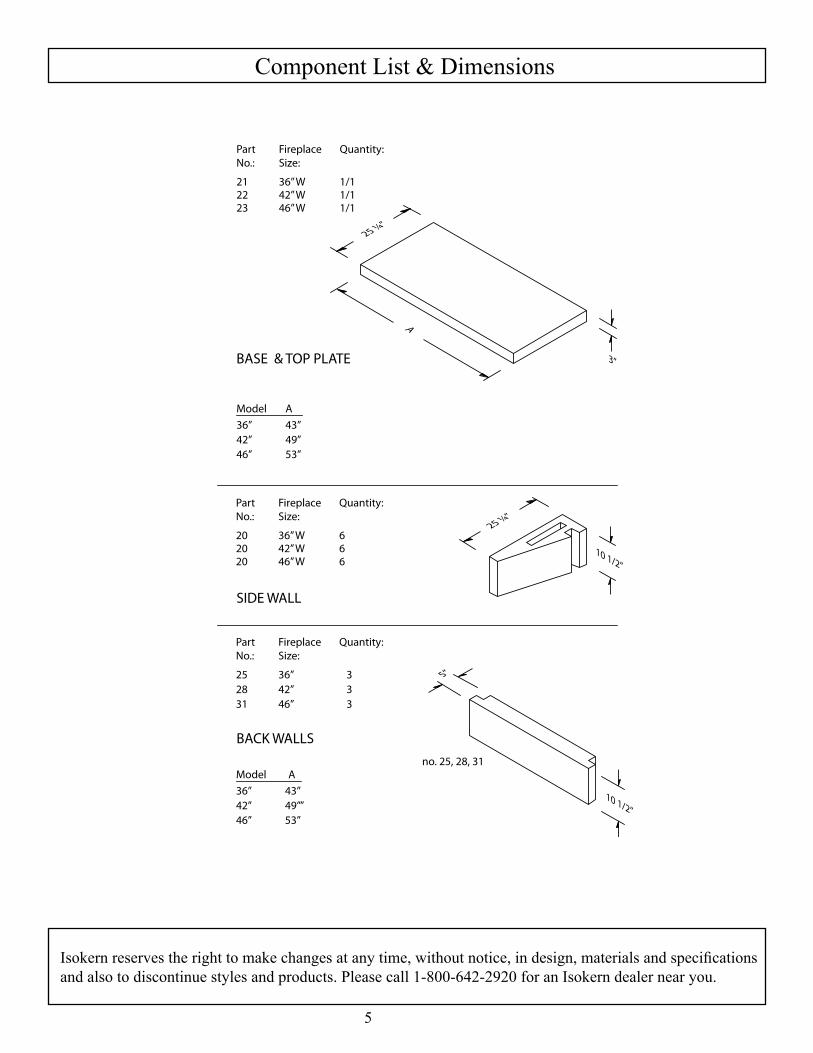
Component List & Dimensions
PartNo.:
212223
FireplaceSize:
36” W42” W46” W
Quantity:
1/11/11/1
PartNo.:
202020
FireplaceSize:
36” W42” W46” W
Quantity:
666
PartNo.:
252831
FireplaceSize:
36” 42” 46”
Quantity:
3 3 3
BASE & TOP PLATE
Model A
36” 43”42” 49”46” 53”
SIDE WALL
BACK WALLS
Model A
36” 43”42” 49””46” 53”
A
10 1/2”
25 ¼”
10 1/2”
25 ¼”
3”
5”
no. 25, 28, 31
Isokern reserves the right to make changes at any time, without notice, in design, materials and specifications and also to discontinue styles and products. Please call 1-800-642-2920 for an Isokern dealer near you.

6
Foundation Requirements
Wood floor framing systems are suitable foundations for the Vent-Free fireplace. Because the Vent-Free fireplace is listed for “zero clearance” at the unit bottom, sides, back and top it may sit directly upon wood sub-flooring. The Vent-Free fireplace weighs approximately 750-900 lbs. (excluding gas log appliance and finish trim). Since thisweight is spread over an area of seven and one-half squarefeet (7.5 sq. feet) to nine and one half square feet (9.5 sq. feet)depending on standard unit size chosen, it is necessary thatany wood floor framing where this unit is placed be designedto carry concentrated loading of approximately 150 lbs/sq.foot. Standard residential concrete slab is a suitable founda-tion. This may be either a structural off-grade slab or a struc-tural slab-on-grade.
Wood Sub-Floor
Wood FloorJoist System
Standard ResidentialConcrete Slab
On or Off-Grade

7
Rough Framing Dimensions
Rough framing dimensions
Model: A B C
36 36 1/8” 34 1/2” 25 1/4”
42 43 1/8” 34 1/2” 25 1/4”
46 47 1/8”” 34 1/2” 25 1/4”
Notes:1. “Raised hearth” requires additional roughopening height at “B” equal to the height of theraised hearth detail.2. “Flush hearth” (non combustible floor only) requires three inches (3”) less at “B”.3. Rough framing dimension for depth “C” allowsfor one and one-half inch (1-1/2”) clearance at theback of the Vent-Free.4. Keep all insulation and vapor barriers threeinches (3”) away from all Vent-Free surfaces.
BFr
amed
Op
enin
gAFramedOpening
C
The following chart of dimensions is intended to aid in the positioning of a Vent-Free fireplace in a corner condition.
Firebox A B C D
Model 36 43” 49” 35” 72”Model 42 49” 52” 37” 75”Model 46 53” 54” 39” 79”
Notes: A. “A” reflects the Vent-Free Series base plate dimension. B. “B” reflects the Vent-Free Series outside center of firebox base plate to inside corner of frame wall.
C. “C” dimension reflects the distance from the corner of the firebox positioned 1 1/2” from frame wall to inside corner of frame wall.
D. “D” dimension reflects the distance from the outside frame wall perpendicular to the firebox to the inside corner of the frame wall.
A
C
D
B

8
Assembly Instructions
Earthcore Mortar: Earthcore Mortar is to be applied to all joints betweenVent-Free fireplace components during field assembly ofthe unit. Thoroughly mix the Earthcore Mortar with cleanwater. Be sure to eliminate any dry pockets or lumps in themortar. The proper finished mixture should be of a“toothpaste” consistency, suitable for application by use ofa standard mason’s grout bag. If the mixture is too thin andrunny then the mortar cannot reach its full strength.Note: When used to assemble the Vent-Free fireplacecomponents Earthcore Mortar is to be mixed only withclean water.Assembling the Vent-Free Fireplace Components: Once the mortar is mixed and loaded into a grout bag it can easily be squeezed out and onto all contact surfaces of the Vent-Free fireplace components as they are fitted together. A Vent-Free fireplace requires approximately twenty-five pounds (25 lbs.) of Earthcore Mortar for proper assembly.Typical grouting procedure is to lay a one half inch (1/2”)bead of mortar approximately one half inch (1/2”) in fromall of the edges of the contact surface of one component.The next mating component is then set in place onto the al-ready grouted contact surface of the first component. Since some of the component contact surfaces are broader areas it is advisable to apply several additional half inch (1/2”) beads of mortar onto these larger contact surfaces to assure proper sealing. Indication of proper sealing of twomating components is that some mortar is squeezed out allalong the contact joint of the two components. The excessgrout can be troweled over the face of the joint.Note: Do not float Earthcore Mortar over the entire face ofany component.Leveling and Aligning Components: Be sure to assemble all Vent-Free fireplace components flush, level and square.Since it is not intended that mortar be used to lay a mortarjoint of any measurable thickness as is typical when layingbrick or concrete block, adjustments in component heightand level alignments are accomplished with the use ofsmall plastic shims (supplied with the unit). These shimscan be tapped into place to level and align components.Once the Earthcore Mortar has set the small leveling shims can be either nipped off flush at the insertion point orremoved completely. Be sure to re-grout any and all gaps where shims have been inserted and then removed or where contact surfaces havebeen separated by shim leveling.Broken Components: Components that are broken from faulty handling can be repaired using Earthcore Mortar. The component that isbroken into two pieces and not fragmented along its breakline can be glued together with Earthcore Mortar in thesame way that two mating components are assembled.
Face and Surface Cracks: Should a face crack appear after the unit is assembled the crack can be repaired in place. Acrack can be “V” notched with a masonry chisel to a depthof approximately three-eighth inch (3/8”). Earthcore Mortaris then squeezed into the face crack and troweled smooth tothe surface of the component.Note: Badly fragmented components should be discardedand replaced.Step 1: Begin assembly by setting the Vent-Free fireplace’sthree inch (3”) thick base plate flat on a suitable level surfaceat zero clearance. This surface can be a concrete slab ora wood floor system capable of 150 psf loading. The baseplate can also be set on a concrete block raised base or on araised wood platform either of which can be built upon astructural slab or upon a structurally suitable wood floorsystem.Step 2: Next set the first course of back wall and side wallsinto place. It may be convenient to scribe the location of thefirst layer of side walls and back wall on the base plate andthen to apply Earthcore Mortar to these scribed areas on thebase plate where the side walls and back wall will sit. In thisway the first layer of walls can be set directly into groutalready applied to the base plate. Be sure to grout thevertical joints where the side wall to back wall connect aseach component is joined to its mate. Look for mortar tosqueeze out of all contact joints as a sign of proper andcomplete sealing of the joints. Continue with the sequential assembly of the second and third courses of the side walls and back wall by firstapplying grout to the top of the previous layer, setting thenext course above into grout already applied to the horizontalcontact surface of the component below. Again besure to grout the vertical joints of the side wall to back wallconnection as each component is joined to its mate. Lookfor some mortar to squeeze out along all joints as a sign ofproper sealing of the joint.Step 3: Once the third, or top course of side walls and backwall are set in place their top surfaces are to be grouted withmortar to receive the Vent-Free fireplace top plate. Set thetop plate upon the completed side wall/back wall assemblyseeing to it that the grouted contact surfaces are properlysealed. This completes the assembly of the Vent-Freefireplace rough box components.Step 4: Make sure that the rough box assembly has been setlevel and square. Adjust to level and square, as necessary,while mortar is still wet. Make a final inspection of allcontact joints to be sure they are properly sealed. Re-groutany and all gaps as necessary.Step 5: The manufacturer requires a minimum one and one eighth inch (1-1/8”) thick fire brick as a liner to the inside ofthe Vent-Free fireplace. Thicker rated fire brick may be usedas an option. Also, the pattern for the fire brick interiorlining is not specified and is to be at owner option.

Base Plate
Raised Platform
Standard ResidentialConcrete Slab
On or Off-Grade
9
Raised and Flush Hearth Application: For a raised hearth (floor of the fireplace elevated above the room’s floor) then the Vent-Free base plate can be set on a concrete block platform that is built up to thedesired raised hearth height on the concrete support slab.When calculating raised hearth height, be sure to allowfor the three inch (3”) thick base plate plus the one andone-half inch (1-1/2”) thick fire brick floor in addition tothe height of the concrete block platform. For a “flush hearth” (fireplace floor flush with the room’s floor) the base plate can be omitted from theassembly and the firebox walls built directly on theconcrete support slab. The fire brick floor of the fireboxis then set directly to the concrete support slab. Thismakes the fireplace finished fire brick floorapproximately one and one-half inches (1-1/2”) abovethe top of the concrete support slab. CMU used for base plate support should be rated ASTM 90.
Assembly Instructions (cont.)

10
Assembly Instructions (cont.)
Through-Wall Accesses:
Gas Line Feed: The provision for installation of a gaspipe is only for connection to a decorative gas applianceor a gas log lighter. The decorative gas appliance mustcomply with standard for Decorative Gas Appliances forinstallation in Vented Fireplaces, ANSI Z21.60. Thedecorative gas appliance should be installed inaccordance with the National Fuel Gas Code, ANSIZ223.1.
Important: If a gas burning decorative appliance isinstalled look for and only use an A.G.A. Certified Vent-Free Gas Log. Anytime a gas fired appliance is in use it is recommended a carbon monoxide detector be installed. Gas line for gas log sets used in the Vent Free firebox canbe routed through the side wall, back wall or floor of the firebox by drilling an appropriately sized hole using a masonry drill bit (Figure 18). Electrical Line Feed can be routed through the firebox back wall, side walls or floor by drilling an appropriately sized hole using a masonry drill bit. Be sure to follow the gas log Appliance Manufacturer’s explicit electrical line connection instructions for vented masonry fireplace installations.
Note: Gas Line and Electric Line must be fed throughseparate access holes.
CAUTION: All access holes must be grouted withmortar to seal any gaps or cracks.
FirebrickSide
Gas or ElectricLine
Typical placement ofgas or electric line
NOTE: Fill any gaps aroundline with Earthcore Mortar

11
Fire Brick Installation
Fire Brick Installation:
The manufacturer requires that the Vent-Free firebox be lined with a minimum one and one-eighth (1-1/8”) thick rated fire brick. The pattern for the fire bricklining is an owner option. Standard N-Type brickmortar is a suitable fire brick mortar for the Vent-Free. All required through-wall accesses (gas and electrical line feeds and combustion air supply access holes) should be drilled before the required fire brick lining is installed. It takes a total of about five gallons of mortar mix (dry measure) to fire brick line a Vent-Free. Face joints of one quarter inch (1/4”) to three-eighths inch (3/8”) give a good appearance to the fin-ished rick-work. However, larger face joint dimensions are also acceptable.
Step 1. Wet mop the inside of the Vent-Free with adamp sponge to remove dust and loose particles fromthe interior before installing fire brick.
Step 2. Start the fire brick at the front edge of thefloor of the Isokern firebox, proceeding inwardtoward the back.
Step 3. Next, apply fire brick to the back wall of theunit starting at the bottom of the back wall andworking upward to the top of the back wall.
Step 4. Finally, set the side wall fire brick by startingat the front edge of the unit’s side wall and workinginward toward the back wall fire brick.
½“ ExpansionGap
Fire brick floor(built first)
½“ Expansion Gap
(No Gaps)
Firebrick Floor &Back Wall (built first)

25 ¼”
B
A
C
Model A B C
36” 43” 37” 53”
42” 49” 43” 59”
46” 53” 47” 63”
12
Specialty Applications: See-Thru
The firebox side walls must sit three inches(3”) on the base plate. Since the side wall componentsflair from three inches (3”) at the narrow end to eightinches (8”) on the wide end, the side walls willoverhang the base plate by approximately five inches(5”) at their wide end. Support this overhang withmasonry. See-Thru or two-sided Vent-Free fireplace canbe constructed from the standard one-sided unitcomponents by eliminating the back wall assembly. In this installation the standard side wallcomponents are reversed so that the standard sidewall taper sits to the outside of the box leaving theinside of the see-thru firebox with two straight andparallel interior walls. Angle steel three inch by three inch by one-quarter inch (3” x 3” x 1/4”) should be set on top ofthe side wall assembly to span each of the openingsof the see-thru before the top plate is set into place.The steel can be set with the angle leg either up ordown.
13
Noncombustible Finished Facing Requirements & Clearance to Combustibles
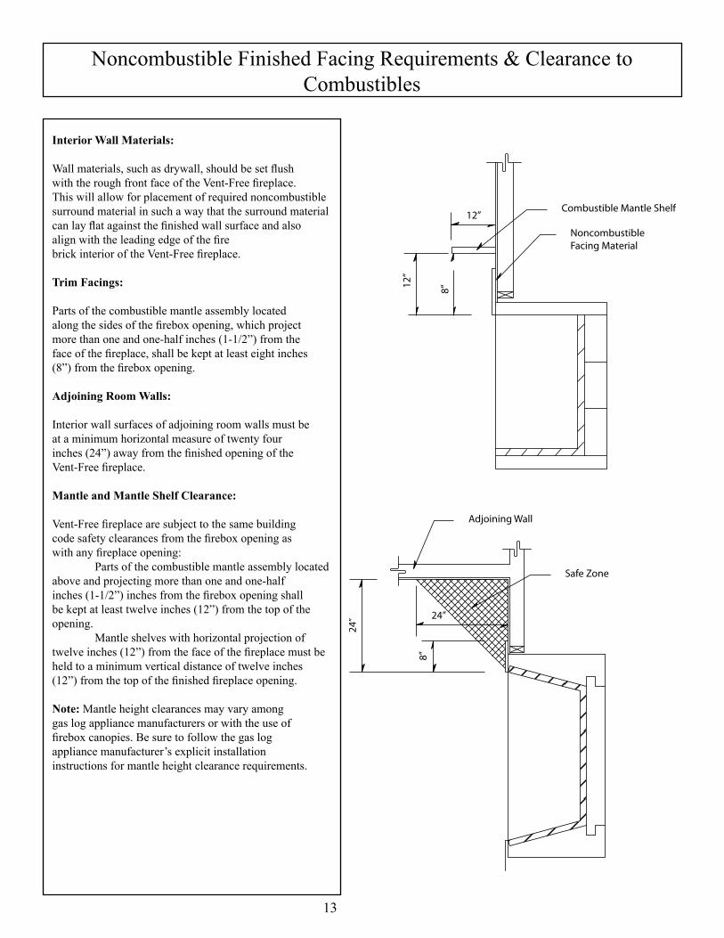
Interior Wall Materials:
Wall materials, such as drywall, should be set flushwith the rough front face of the Vent-Free fireplace.This will allow for placement of required noncombustiblesurround material in such a way that the surround material can lay flat against the finished wall surface and also align with the leading edge of the firebrick interior of the Vent-Free fireplace.
Trim Facings:
Parts of the combustible mantle assembly locatedalong the sides of the firebox opening, which projectmore than one and one-half inches (1-1/2”) from theface of the fireplace, shall be kept at least eight inches(8”) from the firebox opening.
Adjoining Room Walls:
Interior wall surfaces of adjoining room walls must beat a minimum horizontal measure of twenty fourinches (24”) away from the finished opening of theVent-Free fireplace.
Mantle and Mantle Shelf Clearance:
Vent-Free fireplace are subject to the same buildingcode safety clearances from the firebox opening aswith any fireplace opening: Parts of the combustible mantle assembly locatedabove and projecting more than one and one-halfinches (1-1/2”) inches from the firebox opening shallbe kept at least twelve inches (12”) from the top of theopening. Mantle shelves with horizontal projection of twelve inches (12”) from the face of the fireplace must beheld to a minimum vertical distance of twelve inches(12”) from the top of the finished fireplace opening.
Note: Mantle height clearances may vary amonggas log appliance manufacturers or with the use offirebox canopies. Be sure to follow the gas logappliance manufacturer’s explicit installationinstructions for mantle height clearance requirements.
Adjoining Wall
Safe Zone
8”
24” 24”
12”
12”
NoncombustibleFacing Material
Combustible Mantle Shelf
8”

14
Summary
Fireplace Doors and Screens:
This fireplace has not been tested for use with doors. To reduce the risk of fire or injury, do notinstall doors. If doors are required by the local authority having jurisdiction then doors must bekept in the fully open position when the fireplace is in operation. Isokern does not limit the use offireplace screens. Follow screen manufacturer’s explicit use instructions when using fireplacescreens with a Standard fireplace.
Maintenance:
The Vent-Free fireplace does not require any routine maintenance procedure. However, theowner must follow the gas log manufacturer’s explicit instructions regarding burner limitations,burner adjustment, maintenance and cleaning. Any and all questions and concerns regarding theperformance of gas log sets must be directed to the gas log appliance manufacturer or theappliance manufacturer’s agent or supplier.
Dual Listed Appliance:
The Vent-Free fireplace is certified with the use of dual-listed unvented gas log heaters with amaximum input of 40,000 Btu’s. Do not burn any other type of vented gas log, fire wood, paper orrefuse in the Vent-Free fireplace.
Fuel:
Do not introduce any type of fuel into the Vent-Free fireplace other than the LP or Natural Gaslisted for use in the vent free gas log appliance manufacturer’s explicit installation instructions.
Electronic Equipment:Do not place electronic equipment such as television sets, DVD players, audio equipment orcomputer equipment directly above the Vent-Free fireplace.
Dead Loads:
Do not bear structural members nor set structural loads on top of the Vent-Free fireplace. TheVent-Free fireplace is designed to carry none other than its own dead weight.
CAUTION: Do not touch hot surfaces surrounding this unit while it is in operation.Keep infants, toddlers and children away from the Vent-Free fireplace while it is in operation.Do not leave children unattended while it is in use.

15
Notes

Warranty & DisclaimerIsokern FIreplace
ISOKERN offers a lifetime warranty for all Isokern fireboxes, to be free from defects in materials that negatively affect system performance from the date of purchase, subject to the terms and conditions of this limited warranty.
This warranty covers only the above stated components, and NO WARRANTY, EXPRESS OR IMPLIED,EXTENDS TO ANY OF THE HARDWARE, FOOTING, VENTS, DUCTING, METAL FLUES, FIRE BRICK OR ACCESSORIES. THIS WARRANTY DOES NOT COVER DRAFTING, SMOKING OR PUFFING OF THE FIREPLACE SYSTEM. Factors beyond the manufacturer's control affect fireplace drafting, smoking, and puffing, and ISOKERN cannot guarantee these aspects of performance.
If a component is found to be defective under the terms of this warranty the party to whom this warranty isextended shall, notify ISOKERN, 6899 Philips Industrial Blvd, Jacksonville, Florida 32256, in writing, byregistered mail, within thirty (30) days following the discovery of the defect within the lifetime warranty period. The notice shall contain (1) the date of purchase; (2) place of purchase; (3) address of installation; (4) name, address and phone number of the owner; and (5) a brief description of the defect.
ISOKERN, or any division thereof, is not responsible for any labor costs or indirect costs incurred for thereplacement of defective components.
ISOKERN is not responsible for misuse or mishandling of components. Nothing in this warranty makesISOKERN, or any division thereof, liable in any respect for any injury or damage to the building or struc-ture in which the fireplace or chimney system has been installed or to persons or property therein arising out of the use, misuse, or installation of properly manufactured ISOKERN product.
ISOKERN, OR ANY DIVISION THEREOF, SHALL NOT BE HELD LIABLE FOR ANY INCIDENTALOR CONSEQUENTIAL DAMAGES OR EXPENSES ARISING OUT OF THE USE OF THEFIREPLACES OR CHIMNEY SYSTEMS. ALL SUCH DAMAGES AND EXPENSES ARE HEREBYEXCLUDED.
This warranty is null and void when the fireplace or chimney systems are not installed pursuant to the installation instructions provided by ISOKERN or local building codes have not been followed completely.
This warranty applies only to those fireplace and chimney systems installed in the continental United States, Alaska, and Canada. If any part of this warranty is found to be unenforceable, the remaining parts shall remain in force and effect.
ISOKERN HEREBY DISCLAIMS ALL GUARANTEES AND WARRANTIES, EXPRESS OR IMPLIED, BEYOND THE WARRANTIES SET FORTH HEREIN.
6899 PHILIPS INDUSTRIAL BLVD. • JACKSONVILLE, FLORIDA 32256TEL (904) 363-3417 • TOLL 1 (800) 642-2920 • FAX (904) 363-3408