ippc s5.03 guidance for the treatment of landfill leachate …€¦ · · 2014-11-24guidance for...
TRANSCRIPT
www.environment-agency.gov.uk
Sector Guidance Note IPPC S5.03
Integrated Pollution Prevention and Control (IPPC)
Guidance for the Treatment of Landfill Leachate
Guidance for the Treatment of Landfill Leachate
Page 2 of 182
Sector Guidance Note IPPC S5.03 – February 2007
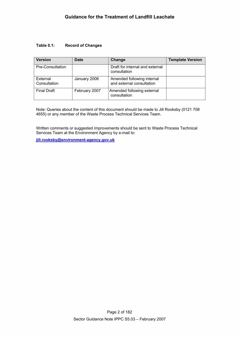
Table 0.1: Record of Changes
Version Date Change Template Version
Pre-Consultation Draft for internal and externalconsultation
ExternalConsultation
January 2006 Amended following internaland external consultation
Final Draft February 2007 Amended following externalconsultation
Note: Queries about the content of this document should be made to Jill Rooksby (0121 7084655) or any member of the Waste Process Technical Services Team.
Written comments or suggested improvements should be sent to Waste Process TechnicalServices Team at the Environment Agency by e-mail to:
Guidance for the Treatment of Landfill Leachate
Page 3 of 182
Sector Guidance Note IPPC S5.03 – February 2007
Executive SummaryThis guidance has been produced by the Environment Agency for England andWales and the Northern Ireland Environment and Heritage Service (EHS) and theScottish Environment Protection Agency (SEPA). Together these are referred to as“the regulator” throughout this document. Its publication follows consultation withindustry, Government departments and non-governmental organisations.
This guidance and theBREF
This UK guidance for delivering the PPC (IPPC) Regulations for LeachateTreatment has considered BAT Reference document BREF (Reference Documenton Best Available Techniques for Waste Treatment Industries dated August 2005)produced by the European Commission. The BREF is the result of an exchange ofinformation between member states and industry. The quality, comprehensivenessand usefulness of the BREF is acknowledged. This guidance is designed tocomplement the BREF and concentrates specifically on Leachate Treatment. Ittakes into account the information contained in the BREF and lays down theindicative standards and expectations in the UK (England and Wales, Scotlandand Northern Ireland).
The aims of thisguidance
The aims of this guidance are to:
• provide a clear structure and methodology for operators to follow to ensurethey address all aspects of the PPC Regulations and other relevantRegulations
• minimise the effort by both operator and regulator in the permitting of aninstallation by expressing the BAT techniques as clear indicative standards
• improve the consistency of applications by ensuring that all relevant issues areaddressed
• increase the transparency and consistency of regulation by having a structurein which the operator's response to each issue, and any departures from thestandards, can be seen clearly and which enables applications to be compared
To assist operators in making applications, separate, horizontal guidance isavailable on a range of topics such as waste minimisation, monitoring, calculatingstack heights and so on. Most of this guidance is available free through theEnvironment Agency or EHS (Northern Ireland) and the Scottish EnvironmentProtection Agency (SEPA) websites (see Reference).
Guidance for the Treatment of Landfill Leachate
Page 4 of 182
Sector Guidance Note IPPC S5.03 – February 2007
Key environmentalissues
The key environmental issues for this sector are:
• Emissions to sewer – discharge to sewer and co-treatment at a Waste waterTreatment Works (WwTW), is acceptable providing that such discharge andtreatment guarantees an equivalent level of protection of the environment,taken as a whole, as would be achieved if dedicated treatment on-site hadbeen employed.
• Selection of appropriate technique – techniques should be designed andoperated to avoid deliberate or inadvertent production and/or displacement ofsubstances that may be harmful to the environment and to prevent thetransfer of such substances from one environmental medium to another.
• Accident risk – accident risks are increased through any failure in themanagement of leachate.
• Odour associated with fugitive emissions - the handling and treatment ofleachate will potentially lead to odour noticeable beyond the installationboundary.
• Site restoration (prevention of emissions to land) – PPC in common withWaste Management Licensing requires that, on completion of activities, thereshould be no pollution risk from the site.
Guidance for the Treatment of Landfill Leachate
Page 5 of 182
Sector Guidance Note IPPC S5.03 – February 2007
ContentsExecutive Summary.......................................................................................3
1. Introduction ................................................................................................8
1.1 Understanding IPPC ............................................................................................91.2 Making an application........................................................................................121.3 Installations covered .........................................................................................131.4 Timescales..........................................................................................................15
1.4.1 Permit review periods.............................................................................................. 151.4.2 Upgrading timescales for existing plant .................................................................. 15
1.5 Key issues ..........................................................................................................161.6 Summary of releases .........................................................................................201.7 Technical Overview............................................................................................211.8 Economics ..........................................................................................................24
2. Techniques for pollution control ............................................................28
2.1 Introduction ........................................................................................................282.1.1 Leachate acceptance, handling and storage .......................................................... 292.1.2 Acceptance procedures when process materials arrive at the installation ............. 372.1.3 Physical treatment processes ................................................................................. 392.1.4 Chemical treatment processes................................................................................ 682.1.5 Biological treatment processes ............................................................................... 762.1.6 Constructed wetlands............................................................................................ 110
2.2 Emissions control ............................................................................................1172.2.1 Point source emissions to air ................................................................................ 1172.2.2 Point source emissions to surface water and sewer............................................. 1202.2.3 Point source emissions to groundwater ................................................................ 1222.2.4 Fugitive emissions to air........................................................................................ 1242.2.5 Fugitive emissions to surface water, sewer and groundwater .............................. 1252.2.6 Odour..................................................................................................................... 127
2.3 Management .....................................................................................................1302.4 Raw materials ...................................................................................................133
2.4.1 Raw Materials selection ........................................................................................ 1332.4.2 Waste minimisation audit (minimising the use of raw materials) .......................... 1352.4.3 Water use .............................................................................................................. 137
2.5 Waste handling.................................................................................................1392.6 Waste recovery or disposal ............................................................................1402.7 Energy...............................................................................................................142
2.7.1 Basic energy requirements (1) .............................................................................. 1422.7.2 Basic energy requirements (2) .............................................................................. 143
2.8 Accidents ..........................................................................................................1462.9 Noise .................................................................................................................1502.10 Monitoring.......................................................................................................152
2.10.1 Environmental monitoring (beyond installation) .................................................. 1522.10.2 Emissions monitoring .......................................................................................... 1532.10.3 Monitoring of process variables .......................................................................... 1542.10.4 Monitoring standards (Standard Reference Methods) ........................................ 155
2.11 Closure............................................................................................................1572.12 Installation issues ..........................................................................................159
Guidance for the Treatment of Landfill Leachate
Page 6 of 182
Sector Guidance Note IPPC S5.03 – February 2007
3 Emission benchmarks............................................................................160
3.1 Emissions inventory ........................................................................................1603.2 Emissions benchmarks ...................................................................................161
3.2.1 Emissions to air associated with the use of BAT .................................................. 1613.2.2 Emissions to water associated with the use of BAT ............................................. 1623.2.3 Standards and obligations..................................................................................... 1633.2.4 Units for benchmarks and setting limits in permits................................................ 1653.2.5 Statistical basis for benchmarks and limits in permits........................................... 1653.2.6 Reference conditions for releases to air................................................................ 166
4. Impact ...................................................................................................167
4.1 Impact assessment ..........................................................................................1674.2 Waste Management Licensing Regulations ..................................................1694.3 The Habitats Regulations ................................................................................171
Referenced Guidance ................................................................................177Abbreviations.............................................................................................180Appendix 1: Common monitoring and sampling methods ....................181Appendix 2: Equivalent legislation in Scotland, Northern Ireland and 182
Wales
List of figures
2.1 Graph of reduction concentration of dissolved methane2.2 Filtration range comparison2.3 Typical process scheme of a 2 stage RO plant2.4 The moving bed filter process2.5 Relationship between Ammoniacal-N and COD2.6 Typical activated sludge process2.7 Typical arrangement for a horizontal flow reed bed2.8 Removal of COD at Efford leachate treatment plant2.9 Removal of Ammoniacal-N at Efford leachate treatment plant2.10 Typical arrangement of a vertical flow reed bed
List of tables
1.1 Potential pollutant releases1.2 Examples of leachate treatment activities1.3 Trade effluent tariffs 2005-061.4 Leachate treatment costs2.1 Trace organic compounds found in leachate2.2 Retention effect (%) against number of stages2.3 Typical performance from a 2 stage RO with 2 stages HPRO2.4 Performance data from 2 stages RO plants2.5 Treatment of SBR Effluent in a DAF unit at Arpley landfill site2.6 Minden Heisterholz leachate treatment plant values for key metals in leachate2.7 Data for removal of residual organic compounds using PAC2.8 Operating results from MSF evaporation plant2.9 Median values for key metals in leachate2.10 Typical performance of aerobic biological leachate treatment schemes
Guidance for the Treatment of Landfill Leachate
Page 7 of 182
Sector Guidance Note IPPC S5.03 – February 2007
2.11 Median concentrations of trace organic compounds and heavy metals2.12 Typical performance data from lagoon-based SBR treatment2.13 Typical performance data from tank based SBR treatment2.14 Typical performance data from MBR treatment2.15 Loading criteria used for the design of the Pitsea RBC plant2.16 Loading criteria used for the design of the Pitsea RBC plant2.17 Point source emissions to air2.18 Air abatement options key2.19 Examples of raw material usage2.20 Example breakdown of delivered and primary energy consumption2.21 Example format for energy efficiency plan3.1 Emissions to air3.2 Emissions to water4.1 Monitoring technical guidance notes
List of Plates
2.1 Typical methane stripping plant2.2 Typical configuration of a 2 stage RO with leachate tanks2.3 Typical configuration of a 2 stage RO with leachate lagoon2.4 Typical configuration of a 2 stage RO with permeate lagoon2.5 Typical configuration of a 2 stage RO with aerated leachate lagoon2.6 DAF treatment tank at Arpley landfill2.7 Typical reactor for contact with PAC2.8 Typical internal sequential GAC tank2.9 Typical external sequential GAC tank2.10 Small-scale MSF evaporation unit2.11 Typical application of the activated sludge process to leachate2.12 Rising sludge as a consequence of denitrification2.13 Typical lagoon-based SBR2.14 Typical example of buried tank SBR2.15 Typical example of above-ground SBR2.16 Large tank-based SBR System2.17 Smaller tank-based SBR2.18 Pitsea RBC plant2.19 Growth of biofilm on RBC media2.20 View of Monument Hill landfill reed bed2.21 Efford leachate treatment plant reed bed
Guidance for the Treatment of Landfill Leachate
Page 8 of 182
Sector Guidance Note IPPC S5.03 – February 2007
1. Introduction
The status and aimsof this guidance
This guidance has been produced by the; Environment Agency for England andWales; Scottish Environment Protection Agency (SEPA) in Scotland; and theEnvironment and Heritage Service (EHS) in Northern Ireland - each referred to as“the regulator” in this document. Its publication follows consultation with industry,Government departments and non-governmental organisations.
It aims to:
• Provide operators and the regulator’s officers with advice on indicativestandards of operation and environmental performance relevant to theindustrial sector concerned,
• Assist the former in the preparation of applications for PPC Permits, and to
• Assist the latter in the assessment of those applications (and the setting of asubsequent compliance regime).
The use of techniques quoted in the guidance and the setting of emission limitvalues at the benchmark values quoted in the guidance are not mandatory, exceptwhere there are statutory requirements from other legislation. However, theregulator will carefully consider the relevance and relative importance of theinformation in the guidance to the installation concerned when making technicaljudgements about the installation and when setting conditions in the permit, anydepartures from indicative standards being justified on a site-specific basis. Theguidance also aims (through linkage with the application form or template) toprovide a clear structure and methodology for operators to follow to ensure theyaddress all aspects of the PPC Regulations and other relevant Regulations, thatare in force at the time of writing. Also, by expressing the Best AvailableTechniques (BAT) as clear indicative standards wherever possible, it aims tominimise the effort required to permit an installation (by both operator andregulator).
SECTIONS 1.1 to 1.8 INCLUSIVE APPLY TO ENGLAND, WALES ANDNORTHERN IRELAND ONLY. FOR INFORMATION ON THE LEGISLATIONAND ITS INTERPRETATION IN SCOTLAND, PLEASE REFER TO SEPA’SWEBSITE.
Guidance for the Treatment of Landfill Leachate
Page 9 of 182
Sector Guidance Note IPPC S5.03 – February 2007
1.1 Understanding IPPC
IPPC and theRegulations
Integrated Pollution Prevention and Control (IPPC) is a regulatory system thatemploys an integrated approach to control the environmental impacts of certainlisted industrial activities. It involves determination by the regulator of theappropriate controls for those industries to protect the environment, through asingle permitting process. To gain a permit, operators have to demonstrate in theirapplications, in a systematic way, that the techniques they are using or areproposing to use, are the Best Available Techniques (BAT) for their installation,and meet certain other requirements, taking account of relevant local factors.
The essence of BAT is that the techniques selected to protect the environmentshould achieve an appropriate balance between environmental benefits and thecosts incurred by operators. However, whatever the costs involved, no installationmay be permitted where its operation would cause significant pollution.
The three regional versions of the PPC Regulations implement in the UK the ECDirective on IPPC (96/61/EC). Further information on the application of IPPC/PPC,together with Government policy and advice on the interpretation of the English &Welsh Regulations, can be found in IPPC: A Practical Guide published by theDepartment for Environment, Food and Rural Affairs (Defra). The Department ofthe Environment, Northern Ireland has published equivalent guidance on theNorthern Ireland Regulations.
Installation based,NOT nationalemission limits
The BAT approach of IPPC differs from regulatory approaches based on fixednational emissions limits (except where General Binding Rules or StandardPermits are issued). The legal instrument that ultimately defines BAT is the permit,and permits can only be issued at the installation level.
Indicative BATStandards
Indicative BAT standards are laid out in national guidance (such as this) and,where relevant, should be applied unless a different standard can be justified for aparticular installation. BAT includes the technical components, process control,and management of the installation given in Section 2 and the benchmark levelsfor emissions identified in Section 3. Departures from those benchmark levels canbe justified at the installation level by taking into account the technicalcharacteristics of the installation concerned, its geographical location and the localenvironmental conditions. If any mandatory EU emission limits or conditions areapplicable, they must be met, but BAT may go further (see “BAT and EQS” below).
Some industrial sectors for which national guidance is issued are narrow andtightly defined, whilst other sectors are wide and diffuse. This means that wherethe guidance covers a wide variety of processes, and individual techniques are notdescribed in detail, the techniques (and their associated emission levels) whichmight constitute BAT for a particular operation, are more likely to differ, withjustification, from the indicative BAT standards than would be the case for anarrow, tightly-defined sector.
BAT and EQS The BAT approach complements, but differs fundamentally from, regulatoryapproaches based on Environmental Quality Standards (EQS). Essentially, BATrequires measures to be taken to prevent emissions - and measures that simplyreduce emissions are acceptable only where prevention is not practicable. Thus, ifit is economically and technically viable to reduce emissions further, or preventthem altogether, then this should be done irrespective of whether or not EQSs arealready being met. The BAT approach requires us not to consider the environmentas a recipient of pollutants and waste, which can be filled up to a given level, but todo all that is practicable to minimise emissions from industrial activities and theirimpact. The BAT approach first considers what emission prevention can
Guidance for the Treatment of Landfill Leachate
Page 10 of 182
Sector Guidance Note IPPC S5.03 – February 2007
reasonably be achieved (covered by Sections 2 and 3 of this Guidance) and thenchecks to ensure that the local environmental conditions are secure (see Section 4of this Guidance and also Guidance Note IPPC Environmental Assessments forBAT). The BAT approach is therefore the more precautionary one because therelease level achieved may be better than that simply required to meet an EQS.
Conversely, if the application of indicative BAT might lead to a situation in which anEQS is still threatened, a more effective technique is required to be BAT for thatinstallation. The Regulations allow for expenditure beyond indicative BAT wherenecessary, and, ultimately, an installation will only be permitted to operate if it doesnot cause significant pollution.
Further advice on the relationship between BAT, EQSs and other relatedstandards and obligations is given in IPPC: A Practical Guide.
Assessing BAT at thesector level
The assessment of indicative BAT takes place at a number of levels. At theEuropean level, the European Commission issues a “BAT reference document”(BREF) for each main IPPC sector. It also issues “horizontal” BREFs for a numberof general techniques which are relevant across a series of industrial sectors. TheBREFs are the result of an exchange of information between regulators, industryand other interested parties in Member States. Member States should take theminto account when determining BAT, but they are allowed flexibility in theirapplication. UK Sector Guidance Notes like this one take account of informationcontained in relevant BREFs and set out current indicative standards andexpectations in the UK. At national level, techniques that are considered to be BATshould represent an appropriate balance of costs and benefits for a typical, well-performing installation in the sector concerned. They should also be affordablewithout making the sector as a whole uncompetitive, either within Europe or world-wide.
Assessing BAT at theinstallation level
When assessing applicability of sectoral indicative BAT standards at theinstallation level, departures may be justified in either direction. Selection of thetechnique which is most appropriate may depend on local factors and, where theanswer is not self-evident, an installation-specific assessment of the costs andbenefits of the available options will be needed. The regulator’s guidance IPPCEnvironmental Assessments for BAT and its associated software tool may helpwith the assessment. Individual installation or company profitability (as opposed toprofitability of the relevant sector as a whole) is not a factor to be considered,however.
In the assessment of BAT at the installation level, the cost of improvements andthe timing or phasing of that expenditure, are always factors to be taken intoaccount. However, they should only be major or decisive factors in decisions aboutadopting indicative BAT where:
• the installation’s technical characteristics or local environmental conditions canbe shown to be so different from those assumed in the sectoral assessment ofBAT described in this guidance, that the indicative BAT standards may not beappropriate; or
• the BAT cost/benefit balance of an improvement only becomes favourablewhen the relevant item of plant is due for renewal/renovation (e.g.. change to adifferent design of furnace when the existing furnace is due for a rebuild). Ineffect, these are cases where BAT for the sector can be expressed in terms oflocal investment cycles; or
• a number of expensive improvements are needed. In these cases, a phasingprogramme may be appropriate - as long as it is not so drawn out that itappears to be rewarding a poorly performing installation.
In summary, departures by an individual installation from indicative BAT for itssector may be justified on the grounds of the technical characteristics of the
Guidance for the Treatment of Landfill Leachate
Page 11 of 182
Sector Guidance Note IPPC S5.03 – February 2007
installation concerned, its geographical location and the local environmentalconditions - but not on the basis of individual company profitability, or if significantpollution would result. Further information on this can be found in IPPC: A PracticalGuide.
Innovation The regulators encourage the development and introduction of innovativetechniques that advance indicative BAT standards criteria, i.e.. techniques whichhave been developed on a scale which reasonably allows implementation in therelevant sector, which are technically and economically viable and which furtherreduce emissions and their impact on the environment as a whole. One of themain aims of the PPC legislation is continuous improvement in the overallenvironmental performance of installations as a part of progressive sustainabledevelopment. This Sector Guidance Note describes the indicative BAT standardsat the time of writing but operators should keep up-to-date with improvements intechnology - and this guidance note cannot be cited as a reason for not introducingbetter available techniques. The technical characteristics of a particular installationmay also provide opportunities not foreseen in the guidance, and as BAT isdetermined at the installation level (except in the case of General Binding Rules(GBRs)), it is a requirement to consider these even where they go beyond theindicative standards.
New installations Indicative BAT standards apply, where relevant, to both new and existinginstallations, but it will be more difficult to justify departures in the case of newinstallations (or new activities in existing installations) - and for new activities,techniques which meet or exceed indicative BAT requirements should normally bein place before operations start.
Existing installations– installation level
For an existing installation, it may not be reasonable to expect compliance withindicative BAT standards immediately if the cost of doing so is disproportionate tothe environmental benefit to be achieved. In such circumstances, operatingtechniques that are not at the relevant indicative BAT standard may be acceptable,provided that they represent what is considered BAT for that installation andotherwise comply with the requirements of the Regulations. The determination ofBAT for the installation will involve assessment of the technical characteristics ofthe installation and local environmental considerations, but where there is asignificant difference between relevant indicative BAT and BAT for an installation,the permit may require further improvements on a reasonably short timescale.
Existing installations– upgradingtimescales
Where there are departures from relevant indicative BAT standards, operators ofexisting installations will be expected to have upgrading plans and timetables.Formal timescales for upgrading will be set as improvement conditions in thepermits. See Section 1.4.2 for more details.
Guidance for the Treatment of Landfill Leachate
Page 12 of 182
Sector Guidance Note IPPC S5.03 – February 2007
1.2 Making an application
A satisfactory application is made by:
• addressing the issues in Sections 2 and 3 of this guidance;• assessing the environmental impact described in Section 4 (and in England
and Wales Environmental Assessment and Appraisal of BAT (IPPC H1));• demonstrating that the proposed techniques are BAT for the installation.
• providing a site report in accordance with Environment Agency Guidance H7.
In practice, some applicants have submitted far more information than wasneeded, yet without addressing the areas that are most important - and this hasled to extensive requests for further information. In an attempt to focus applicationresponses to the areas of concern to the regulator, Application forms (templates)have been produced by the Environment Agency, and by EHS in Northern Ireland.In addition, as the dates for application have approached, the operators in mostindustrial sectors in England and Wales have been provided with compact discs(CDs) which contain all relevant application forms, technical and administrativeguidance, BREFs and assessment tools, hyper-linked together for ease of use.
For applicants with existing IPC Authorisations or Waste Management Licences,the previous applications may provide much of the information for the PPCapplication. However, where the submitted application refers to informationsupplied with a previous application the operator will need to send fresh copies –though for many issues where there is a tendency for frequent changes of detail(for example, information about the management systems), it will be moreappropriate simply to refer to the information in the application and keep availablefor inspection on site, up-to-date versions of the documents.
Guidance for the Treatment of Landfill Leachate
Page 13 of 182
Sector Guidance Note IPPC S5.03 – February 2007
1.3 Installations covered
This guidance relates to installations containing the activities listed below, asdescribed in Part A(1) of Schedule 1 to The Pollution Prevention and ControlRegulations. The schedules of listed activities are slightly different in NorthernIreland so for their equivalent Regulations see Appendix 2. In Scotland thetechnical standards are applicable although the legislative differences will meanthe scope of the guidance needs to be considered on a site-specific basis.Therefore the operator is advised to discuss the applicability of this guidance withSEPA for sites located in Scotland.
Section 5.3 – Disposal of Waste Other Than by Incineration or Landfill
Part A(1)(a) The disposal of hazardous waste (other than by incineration or landfill) in afacility with a capacity of more than 10 tonnes per day.
(c) Disposal of non-hazardous waste in a facility with a capacity of more than 50tonnes per day by –
(i) biological treatment, not being treatment specified in any paragraph other thanparagraph D8 of Annex IIA to Council Directive 75/442/EEC, which results in finalcompounds or mixtures which are discarded by means of any of the operationsnumbered D1 to D12 in that Annex (D8); or
(ii) physico-chemical treatment, not being treatment specified in any paragraphother than paragraph D9 in Annex IIA to Council Directive 75/442/EEC, whichresults in final compounds or mixtures which are discarded by means of any of theoperations numbered D1 to D12 in that Annex (for example, evaporation, drying,calcination, etc.) (D9).
The Environment Agency considers that disposal of the liquid effluent to sewer iseither a D6 (release into a water body except seas/oceans) or a D7 (release intoseas/oceans including sea-bed insertion) activity depending on the final point ofrelease from the sewerage system.
This guidance also relates to activities forming a directly associated technicalconnection to the following activities, described in Schedule 1 Section 5.2 -Disposal of Waste by Landfill
Part A(1)(a) The disposal of waste in a landfill receiving more than 10 tonnes of waste inany day or with a total capacity of more than 25,000 tonnes, excluding disposals inlandfills taking only inert waste.
(b) The disposal of waste in any other landfill to which the 2002 Regulations apply.
Directly associatedactivities
Environment Agency advice on the composition of English or Welsh installationsand which on-site activities are to be included within it (or them) is given in itsguidance document IPPC Regulatory Guidance Series No. 5 – Interpretation of“Installation” in the PPC Regulations. Operators are advised to discuss thecomposition of their installations with the regulator before preparing theirapplications.
The installation will also include associated activities that have a technicalconnection with the main activities and which may have an effect on emissions andpollution, as well as the main activities described above. These may involveactivities such as:
• the storage and handling of raw materials;
Guidance for the Treatment of Landfill Leachate
Page 14 of 182
Sector Guidance Note IPPC S5.03 – February 2007
• the management, handling and unloading of imported leachates;• the storage and despatch of waste and other materials (primarily sludges from
biological treatment processes);• the control and abatement systems for emissions to all media;• waste treatment or recycling.
For examples of some types of activities covered by this document see section1.7.
Installation and sewerconnection
The definition of sewer is given in Section 1.5 below. In considering whether asewer is part of the installation the usual tests would apply and the decision willdepend on the facts in any given case. The Environment Agency providesguidance on the definition of installation in IPPC Regulatory Guidance Series No. 5– Interpretation of “Installation” in the PPC Regulations.
Any private sewer taking treated leachate from a leachate plant would normallyremain part of the installation until it enters the public sewer or until other usersconnect to it. The length of the private sewer is one of the relevant factors whenconsidering whether the private sewer is part of the same site as the leachatetreatment plant. In cases where private sewers do not form part of the same site asthe installation then appropriate off site conditions may be used to ensure thesewer’s integrity.
Importation ofleachate
In the UK, in some circumstances and at some locations, operators choose totransport leachate from one landfill to a leachate treatment plant located at anothersite.
This may be done for technical reasons such as:
• to enable an optimum disposal route to be used for treated leachate – e.g. alarger surface watercourse, or a more suitable location for discharge of effluentinto the public sewer;
• to allow a single treatment system to be operated, supervised and monitored inan optimum manner. One example might be importation of leachate (bypipeline or tanker), from a small, closed landfill, to a leachate treatment planton a large, operational landfill;
• to provide an optimum blend of leachate quality for the specific treatmentprocess, to encourage most effective and consistent treatment ofcontaminants.
Or, it may be done for economic reasons, for example, where it is more cost-effective to construct and operate a single large leachate treatment plant at onelocation, rather than to provide two smaller, similar plants at two separate landfillsites.
Guidance for the Treatment of Landfill Leachate
Page 15 of 182
Sector Guidance Note IPPC S5.03 – February 2007
1.4 Timescales
1.4.1 Permit review periods
Permits are likely to be reviewed as follows:
• for individual activities not previously subject to regulation under IPC or WasteManagement Licensing, a review should be carried out within four years of theissue of the PPC Permit
• for individual activities previously subject to regulation under IPC or WasteManagement Licensing, a review should be carried out within six years of theissue of the PPC Permit
However, where discharges of Groundwater List I or List II substances have beenpermitted, or where there is disposal of any matter that might lead to an indirectdischarge of any Groundwater List I or II substance, a review must be carried outwithin four years as a requirement of the Groundwater Regulations.
These periods will be kept under review and may be shortened or extended.
1.4.2 Upgrading timescales for existing plantExisting installationtimescales
Unless subject to specific conditions elsewhere in the permit, upgrading timescaleswill be set in the improvement programme of the permit, having regard to thecriteria for improvements in the following two categories:
1 Standard “good-practice” requirements, such as, management systems,waste, water and energy audits, bunding, housekeeping measures to preventfugitive or accidental emissions, good waste handling facilities, and adequatemonitoring equipment. Many of these require relatively modest capitalexpenditure and so, with studies aimed at improving environmentalperformance, they should be implemented as soon as possible and generallywell within 3 years of issue of the permit.
2 Larger, more capital-intensive improvements, such as major changes toreaction systems or the installation of significant abatement equipment. Ideallythese improvements should also be completed within 3 years of permit issue,particularly where there is considerable divergence from relevant indicativeBAT standards, but where justified in objective terms, longer time-scales maybe allowed by the regulator.
Local environmental impacts may require action to be taken more quickly than theindicative timescales above, and requirements still outstanding from any upgradingprogramme in a previous permit should be completed to the original time-scale orsooner. On the other hand, where an activity already operates to a standard that isclose to an indicative requirement a more extended time-scale may be acceptable.Unless there are statutory deadlines for compliance with national or internationalrequirements, the requirement by the regulator for capital expenditure onimprovements and the rate at which those improvements have to be made, shouldbe proportionate to the divergence of the installation from indicative standards andto the environmental benefits that will be gained.
The operator should include in the application a proposed programme in which allidentified improvements (and rectification of clear deficiencies) are undertaken atthe earliest practicable opportunities. The regulator will assess BAT for theinstallation and the improvements that need to be made, compare them with theoperator’s proposals, and then set appropriate improvement conditions in thepermit
Guidance for the Treatment of Landfill Leachate
Page 16 of 182
Sector Guidance Note IPPC S5.03 – February 2007
1.5 Key issuesRelationship to BAT Installations regulated under the PPC regime have to be operated so that “all the
appropriate preventative measures are taken against pollution, in particularthrough the application of the best available techniques” (Regulation 11(2)(a)) and“no significant pollution is caused (Regulation 11(2)(b)). Best available techniques(BAT) provide in principle the basis for emission limit values designed to preventand, where that is not practicable, generally to reduce emissions from theinstallation and the impact on the environment as a whole (Regulation 3). Inaddition, it is necessary to ensure that waste is avoided and where possible isdisposed of “while avoiding or reducing any impact on the environment”(Regulation 11(3)(a)). These represent the key requirements within the PPCRegulations for controlling routine releases from PPC-regulated installations to theenvironment, including to water.
Leachate definition Leachate is a generic term given to water that has come into contact with landfilledwaste materials, and in doing so has dissolved contaminants from them. Thesecontaminants may include organic and inorganic compounds and elements, manyof which will have been released by biological degradation of the wastes. Thisreport specifically considers leachates derived from hazardous and non-hazardouswastes, primarily when these are produced after these materials have beenlandfilled. Nevertheless, leachates generated during other waste treatmentprocess – for example, in mechanical biological treatment of wastes – may oftenhave similar characteristics.
The characteristics of a leachate will depend on the composition and nature of thewaste materials, and where biodegradable wastes have been landfilled, on thestage of decomposition that these wastes have achieved. To this extent, leachateis an unusual wastewater stream, in that although day-to-day strength may beaffected by dilution, (as are many other wastewaters), its overall quality will alsochange over timescales of decades, as wastes progressively decompose.Provision of appropriate leachate treatment facilities must take this into account.Treatment systems suitable for leachates from wastes in early stages ofdecomposition in a landfill, may not necessarily remain appropriate as wastescontinue to decompose further.
Operator Where the leachate plant is part of a larger installation, operated by a differentoperator to that of the landfill, each operator will each require their own permit. TheEnvironment Agency provides guidance in the document IPPC RegulatoryGuidance Series No. 3 - Understanding the meaning of Operator under IPPC.
Disposal to sewer The IPPC Directive sets out at Article 2(6) how indirect releases to water (i.e.releases to sewer) are to be addressed when setting emission limit values fromPPC installations. That provision is repeated within Regulation 12(5) of the PPCRegulations, which states:
“The effect of a waste water treatment plant may be taken into account whendetermining the emission limit values applying in relation to indirect releases intowater from a Part A installation or Part A mobile plant provided that an equivalentlevel of protection of the environment as a whole is guaranteed and taking suchtreatment into account does not lead to higher levels of pollution.”
The BAT approach complements, but differs fundamentally from, regulatoryapproaches based on Environmental Quality Standards (EQS). BAT requiresmeasures to be taken to prevent emissions - and measures that simply reduceemissions are acceptable only where prevention is not practicable. Thus, if it iseconomically and technically viable to reduce emissions further, or prevent themaltogether, then this should be done irrespective of whether or not EQSs arealready being met. The BAT approach requires that the environment is notconsidered as a recipient of pollutants and waste, which can be filled up to a given
Guidance for the Treatment of Landfill Leachate
Page 17 of 182
Sector Guidance Note IPPC S5.03 – February 2007
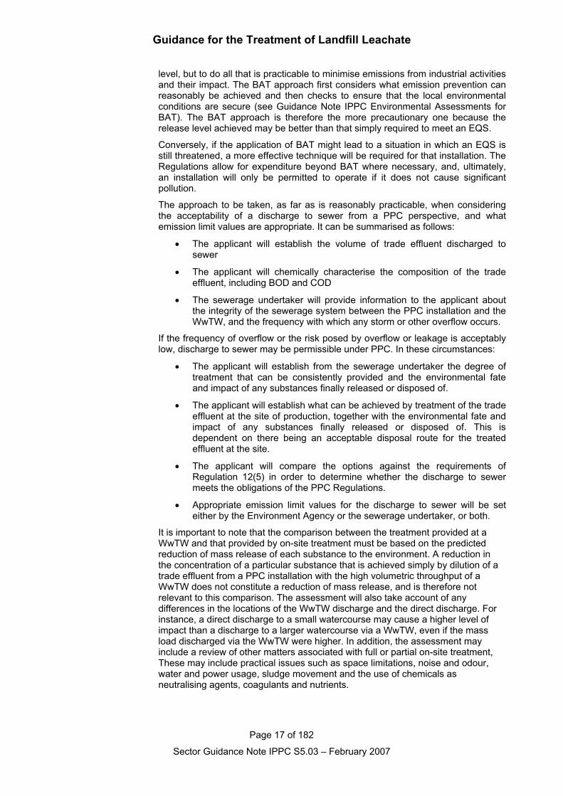
level, but to do all that is practicable to minimise emissions from industrial activitiesand their impact. The BAT approach first considers what emission prevention canreasonably be achieved and then checks to ensure that the local environmentalconditions are secure (see Guidance Note IPPC Environmental Assessments forBAT). The BAT approach is therefore the more precautionary one because therelease level achieved may be better than that simply required to meet an EQS.
Conversely, if the application of BAT might lead to a situation in which an EQS isstill threatened, a more effective technique will be required for that installation. TheRegulations allow for expenditure beyond BAT where necessary, and, ultimately,an installation will only be permitted to operate if it does not cause significantpollution.
The approach to be taken, as far as is reasonably practicable, when consideringthe acceptability of a discharge to sewer from a PPC perspective, and whatemission limit values are appropriate. It can be summarised as follows:
• The applicant will establish the volume of trade effluent discharged tosewer
• The applicant will chemically characterise the composition of the tradeeffluent, including BOD and COD
• The sewerage undertaker will provide information to the applicant aboutthe integrity of the sewerage system between the PPC installation and theWwTW, and the frequency with which any storm or other overflow occurs.
If the frequency of overflow or the risk posed by overflow or leakage is acceptablylow, discharge to sewer may be permissible under PPC. In these circumstances:
• The applicant will establish from the sewerage undertaker the degree oftreatment that can be consistently provided and the environmental fateand impact of any substances finally released or disposed of.
• The applicant will establish what can be achieved by treatment of the tradeeffluent at the site of production, together with the environmental fate andimpact of any substances finally released or disposed of. This isdependent on there being an acceptable disposal route for the treatedeffluent at the site.
• The applicant will compare the options against the requirements ofRegulation 12(5) in order to determine whether the discharge to sewermeets the obligations of the PPC Regulations.
• Appropriate emission limit values for the discharge to sewer will be seteither by the Environment Agency or the sewerage undertaker, or both.
It is important to note that the comparison between the treatment provided at aWwTW and that provided by on-site treatment must be based on the predictedreduction of mass release of each substance to the environment. A reduction inthe concentration of a particular substance that is achieved simply by dilution of atrade effluent from a PPC installation with the high volumetric throughput of aWwTW does not constitute a reduction of mass release, and is therefore notrelevant to this comparison. The assessment will also take account of anydifferences in the locations of the WwTW discharge and the direct discharge. Forinstance, a direct discharge to a small watercourse may cause a higher level ofimpact than a discharge to a larger watercourse via a WwTW, even if the massload discharged via the WwTW were higher. In addition, the assessment mayinclude a review of other matters associated with full or partial on-site treatment,These may include practical issues such as space limitations, noise and odour,water and power usage, sludge movement and the use of chemicals asneutralising agents, coagulants and nutrients.
Guidance for the Treatment of Landfill Leachate
Page 18 of 182
Sector Guidance Note IPPC S5.03 – February 2007
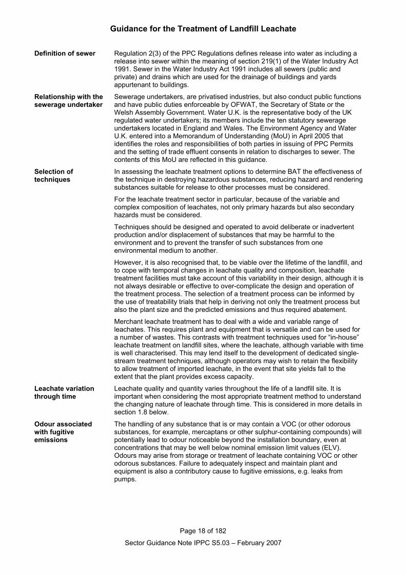
Definition of sewer Regulation 2(3) of the PPC Regulations defines release into water as including arelease into sewer within the meaning of section 219(1) of the Water Industry Act1991. Sewer in the Water Industry Act 1991 includes all sewers (public andprivate) and drains which are used for the drainage of buildings and yardsappurtenant to buildings.
Relationship with thesewerage undertaker
Sewerage undertakers, are privatised industries, but also conduct public functionsand have public duties enforceable by OFWAT, the Secretary of State or theWelsh Assembly Government. Water U.K. is the representative body of the UKregulated water undertakers; its members include the ten statutory sewerageundertakers located in England and Wales. The Environment Agency and WaterU.K. entered into a Memorandum of Understanding (MoU) in April 2005 thatidentifies the roles and responsibilities of both parties in issuing of PPC Permitsand the setting of trade effluent consents in relation to discharges to sewer. Thecontents of this MoU are reflected in this guidance.
Selection oftechniques
In assessing the leachate treatment options to determine BAT the effectiveness ofthe technique in destroying hazardous substances, reducing hazard and renderingsubstances suitable for release to other processes must be considered.
For the leachate treatment sector in particular, because of the variable andcomplex composition of leachates, not only primary hazards but also secondaryhazards must be considered.
Techniques should be designed and operated to avoid deliberate or inadvertentproduction and/or displacement of substances that may be harmful to theenvironment and to prevent the transfer of such substances from oneenvironmental medium to another.
However, it is also recognised that, to be viable over the lifetime of the landfill, andto cope with temporal changes in leachate quality and composition, leachatetreatment facilities must take account of this variability in their design, although it isnot always desirable or effective to over-complicate the design and operation ofthe treatment process. The selection of a treatment process can be informed bythe use of treatability trials that help in deriving not only the treatment process butalso the plant size and the predicted emissions and thus required abatement.
Merchant leachate treatment has to deal with a wide and variable range ofleachates. This requires plant and equipment that is versatile and can be used fora number of wastes. This contrasts with treatment techniques used for “in-house”leachate treatment on landfill sites, where the leachate, although variable with timeis well characterised. This may lend itself to the development of dedicated single-stream treatment techniques, although operators may wish to retain the flexibilityto allow treatment of imported leachate, in the event that site yields fall to theextent that the plant provides excess capacity.
Leachate variationthrough time
Leachate quality and quantity varies throughout the life of a landfill site. It isimportant when considering the most appropriate treatment method to understandthe changing nature of leachate through time. This is considered in more details insection 1.8 below.
Odour associatedwith fugitiveemissions
The handling of any substance that is or may contain a VOC (or other odoroussubstances, for example, mercaptans or other sulphur-containing compounds) willpotentially lead to odour noticeable beyond the installation boundary, even atconcentrations that may be well below nominal emission limit values (ELV).Odours may arise from storage or treatment of leachate containing VOC or otherodorous substances. Failure to adequately inspect and maintain plant andequipment is also a contributory cause to fugitive emissions, e.g. leaks frompumps.
Guidance for the Treatment of Landfill Leachate
Page 19 of 182
Sector Guidance Note IPPC S5.03 – February 2007
Site restoration(prevention ofemissions to land)
PPC in common with Waste Management Licensing requires that, on completionof activities, there should be no pollution risk from the site. Like WasteManagement Licensing, prevention of both short term and long term contaminationof the site requires the provision and maintenance of surfacing, measures toprevent leaks and spillages, containment system that collect any spills or leaks,maintenance of containment systems.
Guidance for the Treatment of Landfill Leachate
Page 20 of 182
Sector Guidance Note IPPC S5.03 – February 2007
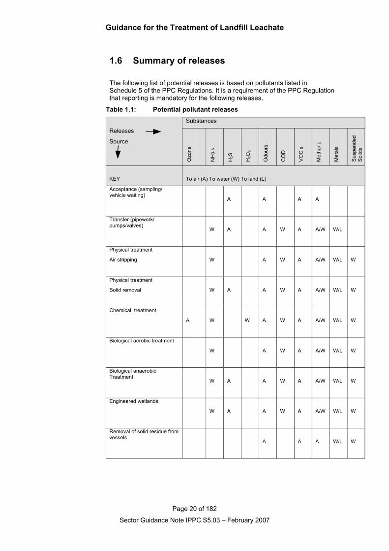
1.6 Summary of releases
The following list of potential releases is based on pollutants listed inSchedule 5 of the PPC Regulations. It is a requirement of the PPC Regulationthat reporting is mandatory for the following releases.
Table 1.1: Potential pollutant releasesSubstances
Releases
Source
Ozo
ne
NH
3-N
H2S
H2O
2
Odo
urs
CO
D
VO
C’s
Met
hane
Met
als
Sus
pend
edS
olid
s
KEY To air (A) To water (W) To land (L)
Acceptance (sampling/vehicle waiting)
A A A A
Transfer (pipework/pumps/valves)
W A A W A A/W W/L
Physical treatment
Air stripping W A W A A/W W/L W
Physical treatment
Solid removal W A A W A A/W W/L W
Chemical treatment
A W W A W A A/W W/L W
Biological aerobic treatment
W A W A A/W W/L W
Biological anaerobicTreatment
W A A W A A/W W/L W
Engineered wetlands
W A A W A A/W W/L W
Removal of solid residue fromvessels
A A A W/L W
Guidance for the Treatment of Landfill Leachate
Page 21 of 182
Sector Guidance Note IPPC S5.03 – February 2007
1.7 Technical Overview
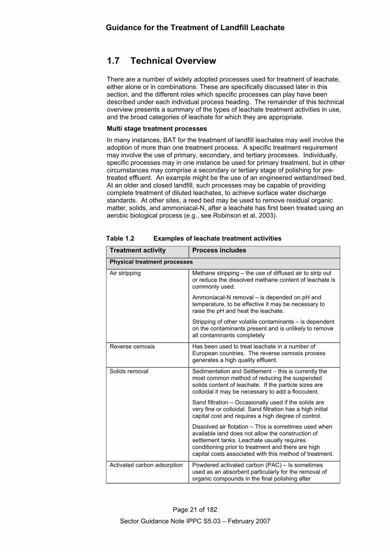
There are a number of widely adopted processes used for treatment of leachate,either alone or in combinations. These are specifically discussed later in thissection, and the different roles which specific processes can play have beendescribed under each individual process heading. The remainder of this technicaloverview presents a summary of the types of leachate treatment activities in use,and the broad categories of leachate for which they are appropriate.
Multi stage treatment processes
In many instances, BAT for the treatment of landfill leachates may well involve theadoption of more than one treatment process. A specific treatment requirementmay involve the use of primary, secondary, and tertiary processes. Individually,specific processes may in one instance be used for primary treatment, but in othercircumstances may comprise a secondary or tertiary stage of polishing for pre-treated effluent. An example might be the use of an engineered wetland/reed bed.At an older and closed landfill, such processes may be capable of providingcomplete treatment of diluted leachates, to achieve surface water dischargestandards. At other sites, a reed bed may be used to remove residual organicmatter, solids, and ammoniacal-N, after a leachate has first been treated using anaerobic biological process (e.g., see Robinson et al, 2003).
Table 1.2 Examples of leachate treatment activities
Treatment activity Process includesPhysical treatment processes
Air stripping Methane stripping – the use of diffused air to strip outor reduce the dissolved methane content of leachate iscommonly used.
Ammoniacal-N removal – is depended on pH andtemperature, to be effective it may be necessary toraise the pH and heat the leachate.
Stripping of other volatile contaminants – is dependenton the contaminants present and is unlikely to removeall contaminants completely
Reverse osmosis Has been used to treat leachate in a number ofEuropean countries. The reverse osmosis processgenerates a high quality effluent.
Solids removal Sedimentation and Settlement – this is currently themost common method of reducing the suspendedsolids content of leachate. If the particle sizes arecolloidal it may be necessary to add a flocculent.
Sand filtration – Occasionally used if the solids arevery fine or colloidal. Sand filtration has a high initialcapital cost and requires a high degree of control.
Dissolved air flotation – This is sometimes used whenavailable land does not allow the construction ofsettlement tanks. Leachate usually requiresconditioning prior to treatment and there are highcapital costs associated with this method of treatment.
Activated carbon adsorption Powdered activated carbon (PAC) – Is sometimesused as an absorbent particularly for the removal oforganic compounds in the final polishing after
Guidance for the Treatment of Landfill Leachate
Page 22 of 182
Sector Guidance Note IPPC S5.03 – February 2007
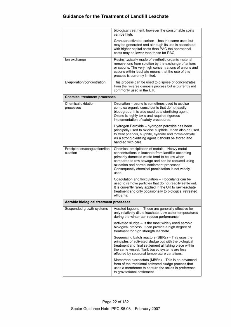
biological treatment, however the consumable costscan be high.
Granular activated carbon – has the same uses butmay be generated and although its use is associatedwith higher capital costs than PAC the operationalcosts may be lower than those for PAC.
Ion exchange Resins typically made of synthetic organic materialremove ions from solution by the exchange of anionsor cations. The very high concentrations of anions andcations within leachate means that the use of thisprocess is currently limited.
Evaporation/concentration This process can be used to dispose of concentratesfrom the reverse osmosis process but is currently notcommonly used in the U.K.
Chemical treatment processes
Chemical oxidationprocesses
Ozonation – ozone is sometimes used to oxidisecomplex organic constituents that do not easilybiodegrade. It is also used as a sterilising agent.Ozone is highly toxic and requires rigorousimplementation of safety procedures.
Hydrogen Peroxide – hydrogen peroxide has beenprincipally used to oxidise sulphide. It can also be usedto treat phenols, sulphite, cyanide and formaldehyde.As a strong oxidising agent it should be stored andhandled with care.
Precipitation/coagulation/flocculation
Chemical precipitation of metals – Heavy metalconcentrations in leachate from landfills acceptingprimarily domestic waste tend to be low whencompared to raw sewage and can be reduced usingoxidation and normal settlement processes.Consequently chemical precipitation is not widelyused.
Coagulation and flocculation – Flocculants can beused to remove particles that do not readily settle out.It is currently rarely applied in the UK to raw leachatetreatment and only occasionally to biological retreatedeffluents.
Aerobic biological treatment processes
Suspended growth systems Aerated lagoons – These are generally effective foronly relatively dilute leachate. Low water temperaturesduring the winter can reduce performance.
Activated sludge – Is the most widely used aerobicbiological process. It can provide a high degree oftreatment for high strength leachate.
Sequencing batch reactors (SBRs) – This uses theprinciples of activated sludge but with the biologicaltreatment and final settlement all taking place withinthe same vessel. Tank based systems are lesseffected by seasonal temperature variations.
Membrane bioreactors (MBRs) – This is an advancedform of the traditional activated sludge process thatuses a membrane to capture the solids in preferenceto gravitational settlement.
Guidance for the Treatment of Landfill Leachate
Page 23 of 182
Sector Guidance Note IPPC S5.03 – February 2007
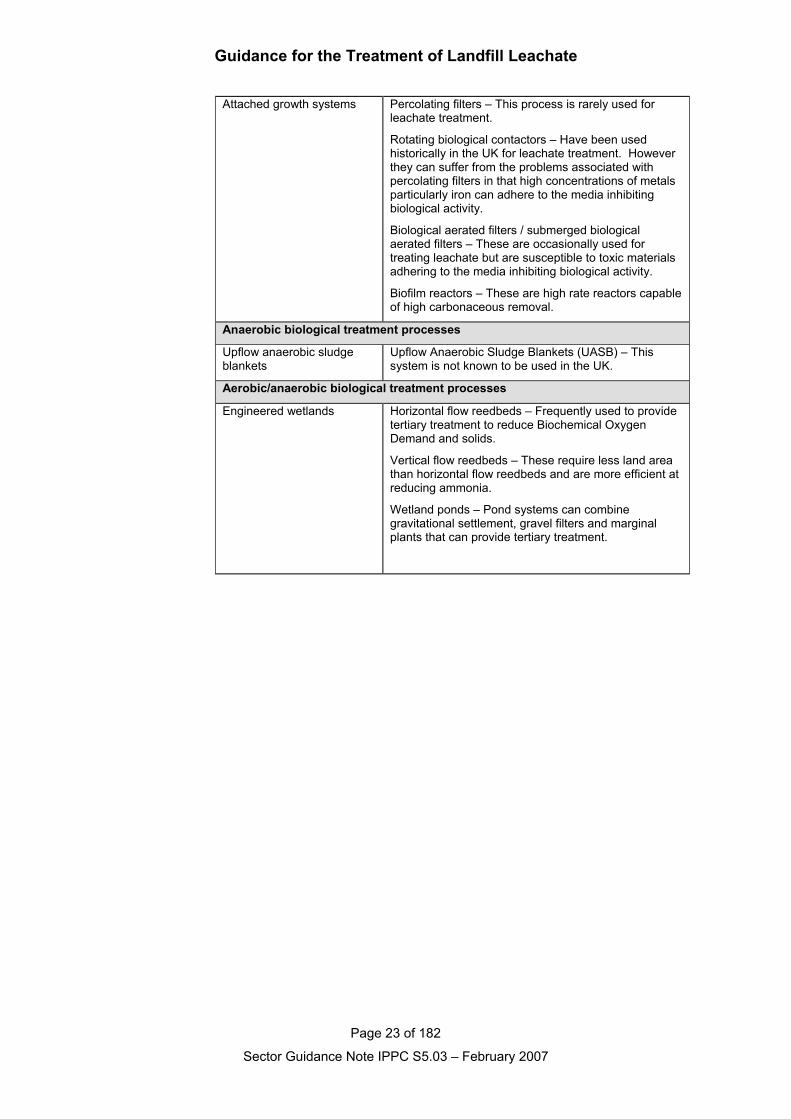
Attached growth systems Percolating filters – This process is rarely used forleachate treatment.
Rotating biological contactors – Have been usedhistorically in the UK for leachate treatment. Howeverthey can suffer from the problems associated withpercolating filters in that high concentrations of metalsparticularly iron can adhere to the media inhibitingbiological activity.
Biological aerated filters / submerged biologicalaerated filters – These are occasionally used fortreating leachate but are susceptible to toxic materialsadhering to the media inhibiting biological activity.
Biofilm reactors – These are high rate reactors capableof high carbonaceous removal.
Anaerobic biological treatment processes
Upflow anaerobic sludgeblankets
Upflow Anaerobic Sludge Blankets (UASB) – Thissystem is not known to be used in the UK.
Aerobic/anaerobic biological treatment processes
Engineered wetlands Horizontal flow reedbeds – Frequently used to providetertiary treatment to reduce Biochemical OxygenDemand and solids.
Vertical flow reedbeds – These require less land areathan horizontal flow reedbeds and are more efficient atreducing ammonia.
Wetland ponds – Pond systems can combinegravitational settlement, gravel filters and marginalplants that can provide tertiary treatment.
Guidance for the Treatment of Landfill Leachate
Page 24 of 182
Sector Guidance Note IPPC S5.03 – February 2007
1.8 EconomicsThe economics concerning leachate treatment are dependent on site specificconditions. The nature of both quantity and quality of the leachate is landfill sitespecific. In addition the landfill site location will influence the practicalities ofconnection to foul sewer. This section considers these and other factors thatinfluence the economic decisions taken when installing a leachate treatment plant.
Leachate production
When considering installing a leachate treatment plant at a landfill it is important toconsider leachate production rates and changes in quality of the leachate whensizing the plant.
Leachate quality and quantity varies throughout the life of a landfill site. The designof the site and the type of waste deposited determine both. As waste changes withtime so does the leachate quality. This is particularly evident in non-hazardouslandfills that have received municipal waste. The initial aerobic condition ofdeposited waste lasts a few days or weeks and is generally not significant indetermining leachate quality. However this is followed by anaerobic conditions, theearly stages (the acidogenic/acetogenic phase) produces leachate with highconcentrations of soluble degradable organic compounds and an acidic pH.Ammonium and metal concentrations increase during this phase. This phase canlast several months or even years until methanogenic conditions are established.During this time leachate pH changes to slightly alkaline and of lowerconcentration (e.g. COD may reduce by 95% and the concentration of heavymetals by 50%), however some pollutants, like ammoniacal nitrogen, may remainrelatively concentrated. In the final stage when biodegradation nears completionaerobic conditions may return and the leachate produced will eventually cease topose an environmental hazard.
It is important to recognise that this process is illustrative of how leachatecomposition changes throughout the life of one type of landfill. The LandfillDirective (Council Directive 1999/31/EC) not only requires waste to deposited inone of three classifications of landfills (hazardous; non-hazardous and inert) butrestricts the proportion of biodegradable waste going to landfill and requires thepre-treatment of certain wastes prior to landfilling. Consequently the composition ofleachate is likely to alter significantly between landfill sites of differentclassifications and between older and newer sites of similar classification.
Leachate quantity can be determined by the overall water balance for each landfillsite. A water balance calculation should assess likely leachate generation volumesconsidering waste volumes, input rates and absorptive capacity, effective and totalrainfall, and infiltration. The leachate generation calculations will provide a likelypredicted volume for design purposes of a leachate treatment facility. Whenlooking at the design of a leachate treatment facility it is advisable to consider aworst case scenario i.e. examination of predicted peak production rather thanaverage predicted production and make allowance for such an occurrence. It isalso advisable to undertake a sensitivity analysis of the data used in predicting theleachate production rates, this should highlight how susceptible the proposedleachate treatment method will be to changes to variables such as waste inputrates or precipitation.
Leachate disposal costs to sewer
Charges for trade effluent to sewer are based on the Mogden formula. Thisformula links charges to the characteristics (volume and strength) of thedischarges which determine the level of treatment needed and therefore the costsinvolved. Sewerage companies calculate the average costs across their regions,so charges do not reflect the costs incurred at any one treatment works.
Guidance for the Treatment of Landfill Leachate
Page 25 of 182
Sector Guidance Note IPPC S5.03 – February 2007
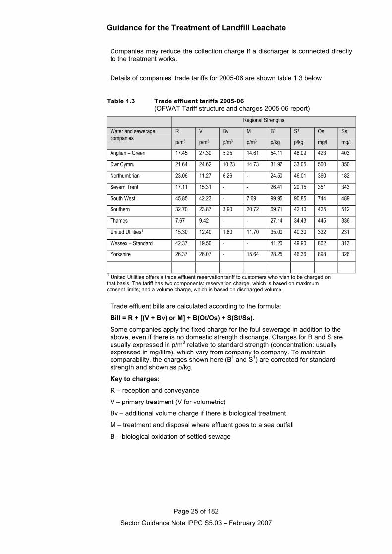
Companies may reduce the collection charge if a discharger is connected directlyto the treatment works.
Details of companies’ trade tariffs for 2005-06 are shown table 1.3 below
Table 1.3 Trade effluent tariffs 2005-06 (OFWAT Tariff structure and charges 2005-06 report)
Regional Strengths
Water and seweragecompanies
R
p/m3
V
p/m3
Bv
p/m3
M
p/m3
B1
p/kg
S1
p/kg
Os
mg/l
Ss
mg/l
Anglian – Green 17.45 27.30 5.25 14.61 54.11 48.09 423 403
Dwr Cymru 21.64 24.62 10.23 14.73 31.97 33.05 500 350
Northumbrian 23.06 11.27 6.26 - 24.50 46.01 360 182
Severn Trent 17.11 15.31 - - 26.41 20.15 351 343
South West 45.85 42.23 - 7.69 99.95 90.85 744 489
Southern 32.70 23.87 3.90 20.72 69.71 42.10 425 512
Thames 7.67 9.42 - - 27.14 34.43 445 336
United Utilities1 15.30 12.40 1.80 11.70 35.00 40.30 332 231
Wessex – Standard 42.37 19.50 - - 41.20 49.90 802 313
Yorkshire 26.37 26.07 - 15.64 28.25 46.36 898 326
1 United Utilities offers a trade effluent reservation tariff to customers who wish to be charged on that basis. The tariff has two components: reservation charge, which is based on maximum consent limits; and a volume charge, which is based on discharged volume.
Trade effluent bills are calculated according to the formula:
Bill = R + [(V + Bv) or M] + B(Ot/Os) + S(St/Ss).
Some companies apply the fixed charge for the foul sewerage in addition to theabove, even if there is no domestic strength discharge. Charges for B and S areusually expressed in p/m3 relative to standard strength (concentration: usuallyexpressed in mg/litre), which vary from company to company. To maintaincomparability, the charges shown here (B1 and S1) are corrected for standardstrength and shown as p/kg.
Key to charges:
R – reception and conveyance
V – primary treatment (V for volumetric)
Bv – additional volume charge if there is biological treatment
M – treatment and disposal where effluent goes to a sea outfall
B – biological oxidation of settled sewage
Guidance for the Treatment of Landfill Leachate
Page 26 of 182
Sector Guidance Note IPPC S5.03 – February 2007
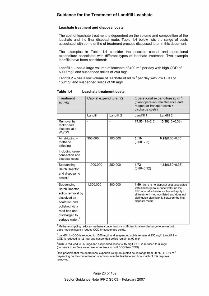
Leachate treatment and disposal costs
The cost of leachate treatment is dependent on the volume and composition of theleachate and the final disposal route. Table 1.4 below lists the range of costsassociated with some of the of treatment process discussed later in this document.
The examples in Table 1.4 consider the possible capital and operationalexpenditure associated with different types of leachate treatment. Two examplelandfills have been considered:
Landfill 1 – has a large volume of leachate of 400 m-3 per day with high COD of6000 mg/l and suspended solids of 250 mg/l.
Landfill 2 – has a low volume of leachate of 60 m-3 per day with low COD of150mg/l and suspended solids of 90 mg/l.
Table 1.4 Leachate treatment costs
Treatmentactivity
Capital expenditure (£) Operational expenditure (£ m-3)(plant operation, maintenance andreagent or transport costs +discharge costs)
Landfill 1 Landfill 2 Landfill 1 Landfill 2
Removal bytanker anddisposal at aWwTW
- - 17.50 (15+2.5) 15.38(15+0.38)
Air stripping –methanestripping
Including sewerconnection anddisposal costs.1
300,000 100,000 3 .10(0.60+2.5)
0.98(0.60+0.38)
SequencingBatch Reactorand disposal tosewer.2
1,000,000 250,000 1.72(0.80+0.92)
1.15(0.80+0.35)
SequencingBatch Reactor,solids removal bydissolved airfloatation andpolished via areed bed anddischarged tosurface water.3
1,500,000 400,000 1.50 (there is no disposal cost associatedwith discharge to surface water as thePPC annual subsistence fee will apply toall treatment methods listed and does notdistinguish significantly between the finaldisposal media)4
1 Methane stripping reduces methane concentrations sufficient to allow discharge to sewer but does not significantly reduce COD or suspended solids.2 Landfill 1 - COD is reduced to 1500 mg/l and suspended solids remain at 250 mg/l. Landfill 2 – COD is reduced to 42 mg/l and suspended solids remain at 90 mg/l3COD is reduced to 650mg/l and suspended solids to 45 mg/l, BOD is reduced to 30mg/l (consents to surface water are more likely to limit BOD than COD).4It is possible that the operational expenditure figure quoted could range from £0.75 - £ 5.50 m-3
depending on the concentration of ammonia in the leachate and how much of this requires removing.
Guidance for the Treatment of Landfill Leachate
Page 27 of 182
Sector Guidance Note IPPC S5.03 – February 2007
The examples given are purely illustrative and not representative of BAT for thegiven landfill. In some of the examples it is unlikely that the proposed leachatetreatment technique would be used. Settlement tanks, for example, may well beemployed in place of dissolved air flotation if available land is available.
Capital expenditure
Other material factors such as available land and proximity of the foul sewer oralternative disposal routes will inform the choice of treatment methods employed.Civil engineering costs can have a significant impact on the capital expenditure,an example being the requirement to construct piled foundations.
Operational expenditure
The concentration of Ammonia is typically the most crucial ‘cost ‘ to considerwhen designing a plant as this requires some 4.5 times more oxygen to oxidisethan COD/BOD. It is also important to note that operational costs may vary onidentical treatment plants treating identical leachates if the consented dischargelimit varies. A lower discharge limit of ammonia for example may requireadditional energy consumption to increase aeration within a sequencing batchreactor in order to reduce the ammonia concentrations.
Guidance for the Treatment of Landfill Leachate
Page 28 of 182
Sector Guidance Note IPPC S5.03 – February 2007
2. Techniques for pollution control
2.1 IntroductionTo assist operators and the regulator’s officers, in respectively making anddetermining applications for PPC permits, this section summarises the indicativeBAT requirements (i.e. what is considered to represent BAT for a reasonablyefficiently operating installation in the sector). The indicative BAT requirementsmay not always be absolutely relevant or applicable to an individual installation,when taking into account site-specific factors, but will always provide a benchmarkagainst which individual applications can be assessed.
Summarised indicative BAT requirements are shown in the “BAT boxes”, theheading of each BAT box indicating which BAT issues are being addressed. Inaddition, the sections immediately prior to the BAT boxes cover the backgroundand detail on which those summary requirements have been based. Togetherthese reflect the requirements for information laid out in the Regulations, soissues raised in the BAT box or in the introductory section ahead of the BATbox both need to be addressed in any assessment of BAT.
Although referred to as indicative BAT requirements, they also cover the otherrequirements of the PPC Regulations and those of other Regulations such as theWaste Management Licensing Regulations (see Appendix 2 for equivalentlegislation in Scotland and Northern Ireland) and the Groundwater Regulations,insofar as they are relevant to PPC permitting.
For further information on the status of indicative BAT requirements, see Section1.1 of this guidance.
It is intended that all of the requirements identified in the BAT sections, both theexplicit ones in the BAT boxes and the less explicit ones in the descriptivesections, should be considered and addressed by the operator in the application.Where particular indicative standards are not relevant to the installation inquestion, a brief explanation should be given and alternative proposals provided.Where the required information is not available, the reason should be discussedwith the regulator before the application is finalised. Where information is missingfrom the application, the regulator may, by formal notice, require its provisionbefore the application is determined.
When making an application, the operator should address the indicative BATrequirements in this guidance note, but also use it to provide evidence that thefollowing basic principles of PPC have been addressed:
• The possibility of preventing the release of harmful substances by changingmaterials or processes, preventing releases of water altogether (see Section2.2.2), and preventing waste emissions by reuse or recovery, have all beenconsidered, and
• Where prevention is not practicable, that emissions that may cause harm havebeen reduced and no significant pollution will result.
This approach should assist applicants to meet the requirements of theRegulations to describe in the applications techniques and measures to preventand reduce waste arisings and emissions of substances and heat - includingduring periods of start-up or shut-down, momentary stoppage, leakage ormalfunction.
In responding to the requirements, the operator should keep the following in mind.
• As a first principle, there should be evidence in the application that fullconsideration has been given to the possibility of PREVENTING the release of
Guidance for the Treatment of Landfill Leachate
Page 29 of 182
Sector Guidance Note IPPC S5.03 – February 2007
harmful substances, for example, by:
− Characterisation of the leachates
− Selection of appropriate treatment techniques.
2.1.1 Leachate acceptance, handling and storage
The first two parts of this section covers the acceptance of leachate generated offsite. The remaining part concerning the storage and handling of leachate isapplicable to all leachate.
Leachate pre-acceptance
Where the treatment plant is to accept leachate other than that directly pumpedfrom the landfill on the same site a pre-acceptance procedure should be employed.This ensures that the leachate is suitable for the proposed treatment. Thesechecks must be carried out before any decision is made to accept the leachate fortreatment.
The operator must establish the composition of the leachate and confirm this byexamining the results of representative samples.
This information must be recorded and referenced to the leachate being accepted.The information must be regularly reviewed and kept up to date with any changesin the leachate.
The producer of the leachate has obligations under the Duty of Care requirementsto provide information on the composition of the leachate, its handlingrequirements and hazards and the appropriate EWC code. This information isrequired on transfer of the leachate between the producer and another party.However should the producer transport leachate to another one of their sites thenthe Duty of Care may not apply. Nevertheless the producer and operator of thereceiving site must ensure that reliable and comprehensive information has beenprovided to determine the suitability of the leachate for the treatment process inquestion.
Adequate sampling and analysis must be carried out to characterise the leachate.In all cases the number of samples taken must be based on an assessment of therisks of potential problems.
Operators should ensure that technical appraisal is carried out by suitably qualifiedand experienced staff who understand the capabilities of the leachate treatmentprocess.Leachate acceptance
For leachate delivered to the site the majority of the characterisation work shouldhave taken place at the pre-acceptance stage. This means that acceptanceprocedures when leachate arrives at the site should serve to confirm thecharacteristics of the leachate.
It is possible that automatic off loading facilities may be used for the delivery ofleachate by tanker providing the issues identified in this section are adequatelyaddressed.
The issues to be addressed by the operator in relation to waste acceptanceprocedures for the site include:
• tanker waiting, load inspection / checking, sampling and discharge areas
• traffic control
• procedures for checking paperwork arriving with the load

Guidance for the Treatment of Landfill Leachate
Page 30 of 182
Sector Guidance Note IPPC S5.03 – February 2007
• location of sampling point(s)
• infrastructure such as bunds
• sampling procedures
• verification and compliance testing
• assess consistency with pre-acceptance information
• rejection criteria
• sample retention system
• record keeping in relation to producer details, analysis results and treatmentmethods
• procedures for periodic review of pre-acceptance information
• identification of operators staff who have taken any decisions concerningacceptance or rejection of leachate.
Notwithstanding the legal requirements of the Duty of Care leachate should not beaccepted without detailed written information identifying its source andcomposition.
Records should be made and kept up to date of all the information generatedduring pre-acceptance, acceptance, storage and treatment (i.e. the point theleachate entered the treatment plant).
Reception facilities must be provided. The design of the reception facilities and theoperational practices should consider normal and abnormal events.
Reception areas need to be able to contain the spills. The size of the containmentarea should be based on a risk assessment that considers the potential for thelargest uncontrolled release. This should consider the potential escape of thewhole of the largest tanker delivering to the site. Containment is likely to includebunding with consideration being given to falls on the site and how a tanker canaccess the area when it is surrounded by bunding.
The surfacing and drainage provided for the reception area will have to bedesigned to prevent short-term discharges of contaminated water and longer termpollution of underlying ground.
The design process should also consider logic systems that can be employed tolimit the potential for wrong connections or incorrect routing while discharges arebeing made.Leachate storage
Leachate storage issues are of primary importance to the design and selection ofleachate collection and treatment systems.
The manner in which leachate is generated from rainfall is in the short-termunpredictable, and during heavy rain takes place at potentially high flow rates.However, leachate storage that balances flow takes place in a landfill when rainfallpercolates through the waste into collection systems. The degree to which thiseffect can be optimised by additional storage, as discussed below, is central to thedesign of leachate treatment processes.
It is unlikely that a biological treatment process can readily be designed, eitherrobustly or cost effectively, with a minimum flow much below 20% of the designcapacity. Although in certain circumstances a reduced flow may provide the camelevels of contaminants and hence load to the treatment process. Any less than20% flow and when the change from low to high flow occurs there may simply notbe adequate biomass present to accomplish treatment at increased throughputs.
Guidance for the Treatment of Landfill Leachate
Page 31 of 182
Sector Guidance Note IPPC S5.03 – February 2007
The sizing and turndown ratio for a process design is critical to the amount ofstorage available to smooth (balance) the peak flows during storms. Even smalladjustments in total site (landfill plus discrete storage/balancing vessel design)storage volume assumptions can potentially double or halve the design throughputrates for treatment facilities.
Short term leachate storage at landfill sites can range from, allowing excessleachate to accumulate in a developed area of the lined landfill within headspermissible within the permit, to purpose-built storage tanks.
Significant operational benefits arise for leachate storage, under circumstancessuch as:-
1. Flow balancing prior to on-site treatment, tankerage off-site, ordischarge to sewer; resulting in a significant reduction in short term peakwet weather flows, which would otherwise result in a requirement forsubstantial additional treatment capacity which would be substantially underutilised for all but very short storm duration periods. (For biological systems itmay not be possible to develop and maintain a viable biomass constantlyavailable for such peaks, and therefore the importance of this form of storageto the viability of these processes should not be underestimated.)
2. Flow balancing for one-off events during the life of a landfill. Allcontainment landfills will produce varying amounts of leachate through thelife of the site. It is inevitable that there will be critical points during thedevelopment of any landfill when the generation of leachate will pose specialproblems. The most likely/frequently observed event is the scenario whichoccurs when a landfill is first developed, and large volumes of leachate maybe generated before there is a significant quantity of waste within the sitephase or cell to absorb rainfall incident on a large cell.
3. Flow balancing winter/summer within the landfill. Where landfills arereasonably shallow and base gradients not severe, the leachate storagevolume which can be held within the permitted leachate head over the linerprovides a storage capability for the well managed landfill. If an operatordraws down the leachate head to almost zero during dry weather periods. Insome instances this effect has been used to allow leachate treatment plantsto be run at a constant flow rate for 9 months of the year avoidingoperationally more difficult winter periods (e.g. for lagoon based leachatetreatment plants).
4. Leachate quality balancing to “blend” different strengths of leachate foroptimum treatment. Biological processes in particular require a reasonablyconstant feed quality as well as quantity, as the biomass available to providetreatment tends to develop/grow during periods of weeks to match the foodsource. Without balancing these changes can occur on a daily basis or morefrequently. Therefore, blending leachates from different cells prior totreatment, where large variations in leachate quality exists between differentleachate sources on a landfill, can be an important and appropriate use ofleachate storage. It is anticipated that flow balancing for blending will becomemore important in future as mechanical biological pre-treatment technologiesare implemented, and different landfill cells are developed for different wastetypes, resulting in greater variation in leachate qualities at individual sites.
5. Leachate “storage” as part of a leachate collection/treatment system.Some leachate collection systems require the storage of small quantities ofleachate in header tanks at the pump location (eductor systems), and onsome large landfills with significant perimeter pipeline runs, header andbreak-pressure tanks may provide storage for leachate in transit. Pre-treatment or post pre-treatment settlement of leachate may be appropriateunder some circumstances, to allow solids to settle prior to discharge for
Guidance for the Treatment of Landfill Leachate
Page 32 of 182
Sector Guidance Note IPPC S5.03 – February 2007
example, or to allow contact time after chemical dosing.
6. Leachate pumps: Some leachate pump systems require the storage ofsmall volumes of leachate as (for example pump priming and pressure surge(pipe hammer) reduction). These storage requirements are small and arejustifiable/low potential impact, and are not discussed further here.
The diversity of uses of leachate storage is therefore very broad, and in manyinstances such storage may be essential to the provision of effective treatment.
It is therefore important for the operator to assess each form of leachate storage inthe context of the risks that it entails, in terms of impacts on Health and Safety andenvironmental considerations. This document concentrates on the environmentalconsiderations.
Within this document we have limited further discussion, the forms of storageafforded by mechanisms 2 & 3 above are not discussed further, as they fall underthe general heading of landfill management.
For similar reasons leachate recirculation, which results in leachate storage bymerit of the fact that a volume of leachate will be held “in-transit” as it percolatesthrough the waste, before the portion which is not absorbed emanates again fromthe drainage system, is not classified as storage within this discussion.
Environmental issues and concerns
The source-term for leachate quality has been well documented. Leachate storedmay comprise any leachate across the full range identified in the source term.
The manner in which leachate changes in nature from fresh “acetogenic” to old“methanogenic” is also well documented. In general terms it is clear that the risk ofimpacts from leachate storage will be greatest from the youngest and strongestleachates, and can reduce with leachate age. Young leachates will contain thegreatest concentrations of odorous chemicals (e.g. volatile organic chemicals(VOCs), mercaptans, and hydrogen sulphide (H2S)).
Any assessment of potential impacts must allow for chemical changes that maytake place during storage and the effects of these on potential impacts. Forexample, a freshly generated leachate from newly deposited, waste may undergodecomposition after storage commences, which results in the generation ofanaerobic conditions, and as a result generates significant odours.
Clearly, storage incurs risks, which encompass all the normal Health and Safetyrisks that arise from the presence of any body of water, but these are assumed tobe included automatically in any assessment, and are not discussed here.
However, stored leachates will impose special Health and Safety risks related tothe generation of methane while stored (if stored under anaerobic conditionswithout mixing or any aeration) and also from dissolved methane which is likely tobe present in all leachate emanating form methanogenic landfill cells/phases.
The principal environmental risks posed by leachate storage are:-
• Odours
• Leakage from storage vessels into surface or groundwater
• Release of dissolved methane from solution
A site specific risk assessment is necessary for each of the above, before suchrisks and suitable ameliorative measures can be identified, that are appropriate tothe specific circumstances of type of storage, nature of leachate stored, nature ofany chemical or biochemical change which might occur during treatment.
The risk of an impact from odour should be considered in respect of the nature andlocation of the receptor, which during the active life of the site may be located at
Guidance for the Treatment of Landfill Leachate
Page 33 of 182
Sector Guidance Note IPPC S5.03 – February 2007
the site perimeter, but may be otherwise after site closure depending upon after-use.
Leachate storage facilities may be roofed in order to prevent the escape of odours.Under such circumstances, consideration should be given to venting which willoccur as a storage vessel fills and displaces air from the air-space above theliquid. If odour generation from the raw leachate is likely to be a particular problem,or there is a history of odour concerns, or the site is in close proximity to sensitivereceptors, aeration air should be drawn from headspace in raw leachate tanks andmaintained under negative pressure and thus reduce the potential for fugitiveemissions.
The prediction of impacts from odours emanating from storage vessels may beassessed using:-
• Evidence of experience elsewhere with similar installations;
• Assessing the results of from trials;
• Reports from odour panels which can provide a rating for the “odour potential”of the leachate if a characteristic and fresh air sample of the relevant off-gas isdispatched when a panel is sitting;
• In some cases it may be necessary to run air dispersion models to predict theeffect of an odour, if the sensitive receptor is remote from the source.
Odour treatment can be carried out to most leachates. Depending on the nature ofthe leachate and odour produced, biological methods and physical/chemicalmethods may be appropriate. Again each method proposed will need to beassessed on a site specific basis.
There will be a predisposition, wherever possible and for most biologically-treatable leachates, to use biological odour treatment techniques, whereby theodorous air is passed through a medium which is maintained at an optimummoisture content (e.g. heather, peat. seaweed, shells etc) and a biomass isallowed to build-up which will bio-chemically oxidise and remove the odours.Activated carbon and resin adsorption based techniques may also be appropriate,subject to consideration of the efficacy and environmental impacts of the creationand disposal of these materials.
To assess the potential impact of leachate storage on a groundwater or surfacewater at any specific site, the following should be considered:-
• Leachate quality;
• Likely modes of failure/possible rates of leakage under a worst case tankfailure scenario (i.e. concrete tanks fail gradually by developing cracks, steeltanks may fail by penetration by corrosion and thus typically results in agreater leakage rate before emergency action can be taken);
• Emergency ameliorative measures and response time after any leak was todevelop;
• The source and receptor relationship (i.e. distance and dilution available in theevent of leakage, which would provide further protection from a groundwaterimpact under the worst case scenario.
Satisfactory ameliorative measures can be utilised, under circumstances wherebunding would otherwise be necessary, subject to compliance with therequirements of the risk assessment, such as:-
For entirely above ground vessels;
• Regular inspection and maintenance, provided that any leakage is adequatelycontained (this may include the return of leachate to the landfill of its origin via
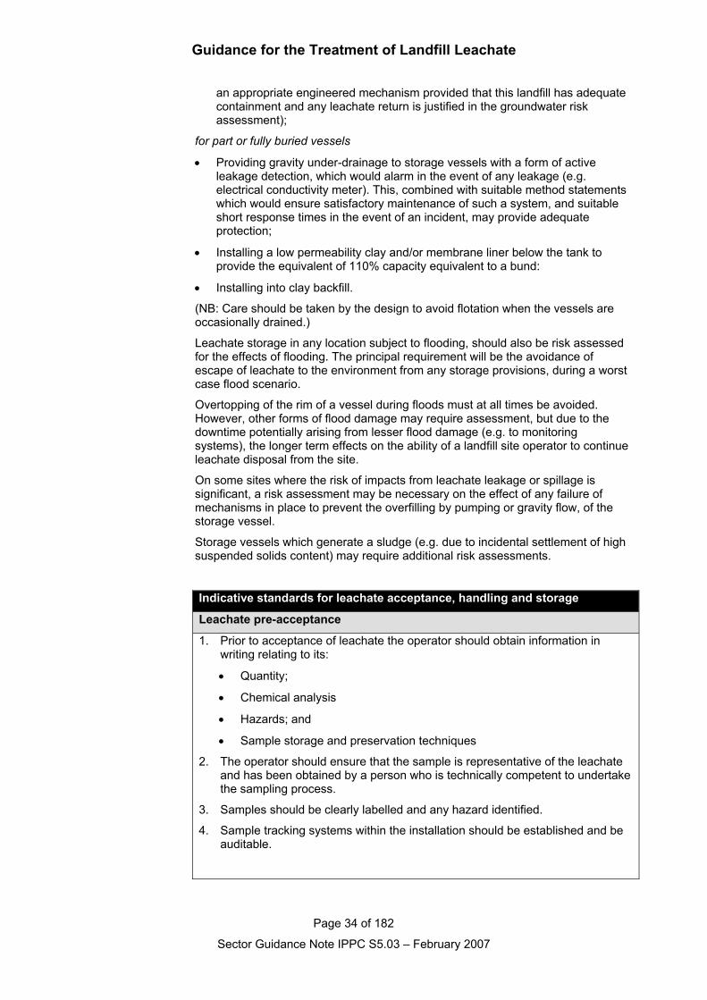
Guidance for the Treatment of Landfill Leachate
Page 34 of 182
Sector Guidance Note IPPC S5.03 – February 2007
an appropriate engineered mechanism provided that this landfill has adequatecontainment and any leachate return is justified in the groundwater riskassessment);
for part or fully buried vessels
• Providing gravity under-drainage to storage vessels with a form of activeleakage detection, which would alarm in the event of any leakage (e.g.electrical conductivity meter). This, combined with suitable method statementswhich would ensure satisfactory maintenance of such a system, and suitableshort response times in the event of an incident, may provide adequateprotection;
• Installing a low permeability clay and/or membrane liner below the tank toprovide the equivalent of 110% capacity equivalent to a bund:
• Installing into clay backfill.
(NB: Care should be taken by the design to avoid flotation when the vessels areoccasionally drained.)
Leachate storage in any location subject to flooding, should also be risk assessedfor the effects of flooding. The principal requirement will be the avoidance ofescape of leachate to the environment from any storage provisions, during a worstcase flood scenario.
Overtopping of the rim of a vessel during floods must at all times be avoided.However, other forms of flood damage may require assessment, but due to thedowntime potentially arising from lesser flood damage (e.g. to monitoringsystems), the longer term effects on the ability of a landfill site operator to continueleachate disposal from the site.
On some sites where the risk of impacts from leachate leakage or spillage issignificant, a risk assessment may be necessary on the effect of any failure ofmechanisms in place to prevent the overfilling by pumping or gravity flow, of thestorage vessel.
Storage vessels which generate a sludge (e.g. due to incidental settlement of highsuspended solids content) may require additional risk assessments.
Indicative standards for leachate acceptance, handling and storage
Leachate pre-acceptance
1. Prior to acceptance of leachate the operator should obtain information inwriting relating to its:
• Quantity;
• Chemical analysis
• Hazards; and
• Sample storage and preservation techniques
2. The operator should ensure that the sample is representative of the leachateand has been obtained by a person who is technically competent to undertakethe sampling process.
3. Samples should be clearly labelled and any hazard identified.
4. Sample tracking systems within the installation should be established and beauditable.
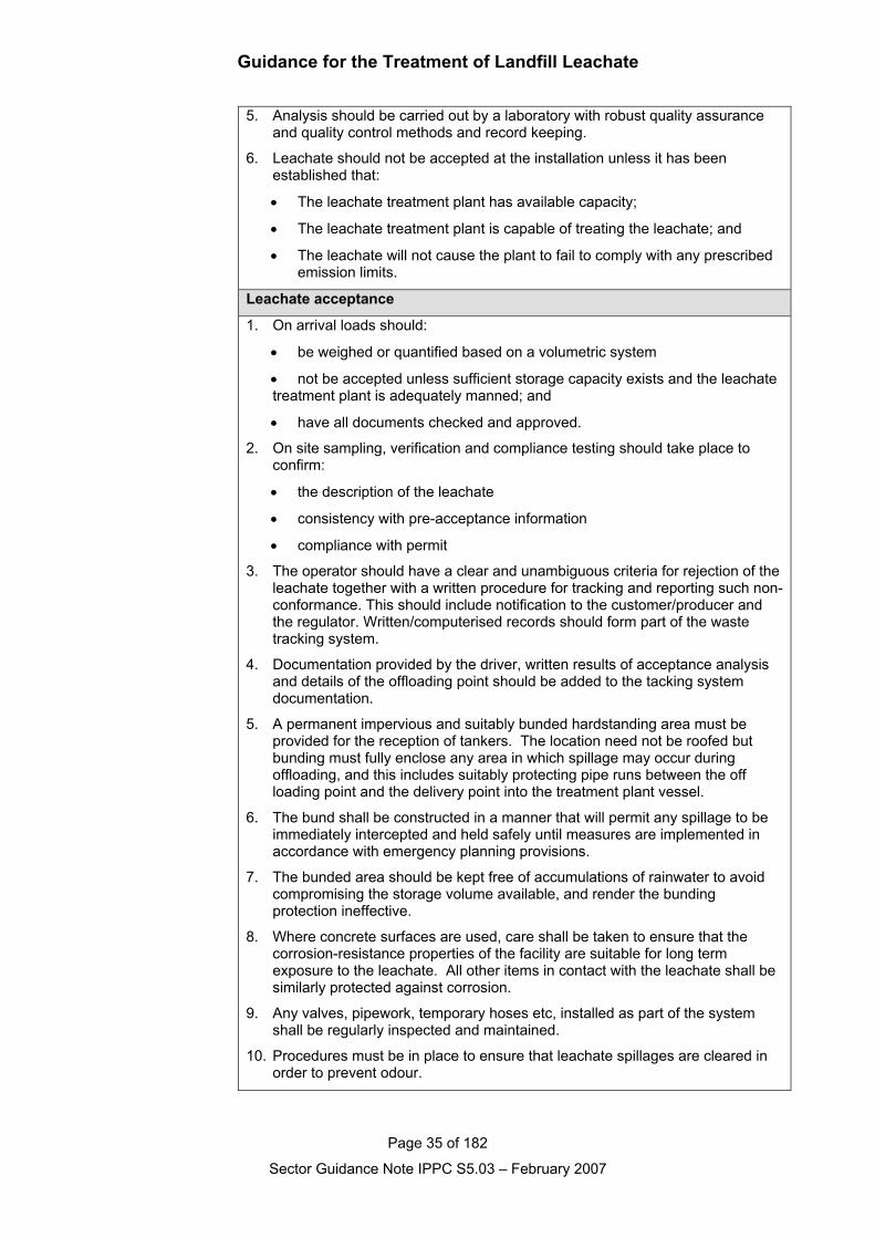
Guidance for the Treatment of Landfill Leachate
Page 35 of 182
Sector Guidance Note IPPC S5.03 – February 2007
5. Analysis should be carried out by a laboratory with robust quality assuranceand quality control methods and record keeping.
6. Leachate should not be accepted at the installation unless it has beenestablished that:
• The leachate treatment plant has available capacity;
• The leachate treatment plant is capable of treating the leachate; and
• The leachate will not cause the plant to fail to comply with any prescribed emission limits.
Leachate acceptance
1. On arrival loads should:
• be weighed or quantified based on a volumetric system
• not be accepted unless sufficient storage capacity exists and the leachatetreatment plant is adequately manned; and
• have all documents checked and approved.
2. On site sampling, verification and compliance testing should take place toconfirm:
• the description of the leachate
• consistency with pre-acceptance information
• compliance with permit
3. The operator should have a clear and unambiguous criteria for rejection of theleachate together with a written procedure for tracking and reporting such non-conformance. This should include notification to the customer/producer andthe regulator. Written/computerised records should form part of the wastetracking system.
4. Documentation provided by the driver, written results of acceptance analysisand details of the offloading point should be added to the tacking systemdocumentation.
5. A permanent impervious and suitably bunded hardstanding area must beprovided for the reception of tankers. The location need not be roofed butbunding must fully enclose any area in which spillage may occur duringoffloading, and this includes suitably protecting pipe runs between the offloading point and the delivery point into the treatment plant vessel.
6. The bund shall be constructed in a manner that will permit any spillage to beimmediately intercepted and held safely until measures are implemented inaccordance with emergency planning provisions.
7. The bunded area should be kept free of accumulations of rainwater to avoidcompromising the storage volume available, and render the bundingprotection ineffective.
8. Where concrete surfaces are used, care shall be taken to ensure that thecorrosion-resistance properties of the facility are suitable for long termexposure to the leachate. All other items in contact with the leachate shall besimilarly protected against corrosion.
9. Any valves, pipework, temporary hoses etc, installed as part of the systemshall be regularly inspected and maintained.
10. Procedures must be in place to ensure that leachate spillages are cleared inorder to prevent odour.
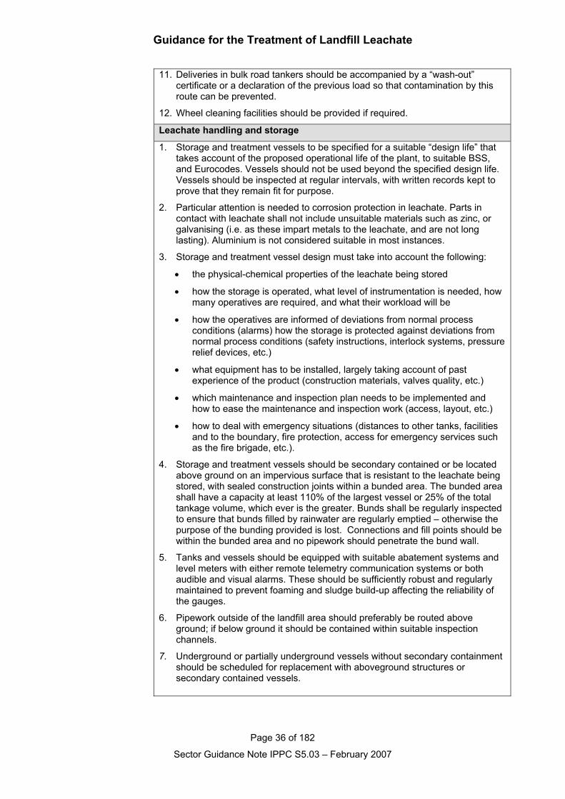
Guidance for the Treatment of Landfill Leachate
Page 36 of 182
Sector Guidance Note IPPC S5.03 – February 2007
11. Deliveries in bulk road tankers should be accompanied by a “wash-out”certificate or a declaration of the previous load so that contamination by thisroute can be prevented.
12. Wheel cleaning facilities should be provided if required.
Leachate handling and storage
1. Storage and treatment vessels to be specified for a suitable “design life” thattakes account of the proposed operational life of the plant, to suitable BSS,and Eurocodes. Vessels should not be used beyond the specified design life.Vessels should be inspected at regular intervals, with written records kept toprove that they remain fit for purpose.
2. Particular attention is needed to corrosion protection in leachate. Parts incontact with leachate shall not include unsuitable materials such as zinc, orgalvanising (i.e. as these impart metals to the leachate, and are not longlasting). Aluminium is not considered suitable in most instances.
3. Storage and treatment vessel design must take into account the following:
• the physical-chemical properties of the leachate being stored
• how the storage is operated, what level of instrumentation is needed, howmany operatives are required, and what their workload will be
• how the operatives are informed of deviations from normal process conditions (alarms) how the storage is protected against deviations from normal process conditions (safety instructions, interlock systems, pressurerelief devices, etc.)
• what equipment has to be installed, largely taking account of past experience of the product (construction materials, valves quality, etc.)
• which maintenance and inspection plan needs to be implemented and how to ease the maintenance and inspection work (access, layout, etc.)
• how to deal with emergency situations (distances to other tanks, facilities and to the boundary, fire protection, access for emergency services such as the fire brigade, etc.).
4. Storage and treatment vessels should be secondary contained or be locatedabove ground on an impervious surface that is resistant to the leachate beingstored, with sealed construction joints within a bunded area. The bunded areashall have a capacity at least 110% of the largest vessel or 25% of the totaltankage volume, which ever is the greater. Bunds shall be regularly inspectedto ensure that bunds filled by rainwater are regularly emptied – otherwise thepurpose of the bunding provided is lost. Connections and fill points should bewithin the bunded area and no pipework should penetrate the bund wall.
5. Tanks and vessels should be equipped with suitable abatement systems andlevel meters with either remote telemetry communication systems or bothaudible and visual alarms. These should be sufficiently robust and regularlymaintained to prevent foaming and sludge build-up affecting the reliability ofthe gauges.
6. Pipework outside of the landfill area should preferably be routed aboveground; if below ground it should be contained within suitable inspectionchannels.
7. Underground or partially underground vessels without secondary containmentshould be scheduled for replacement with aboveground structures orsecondary contained vessels.
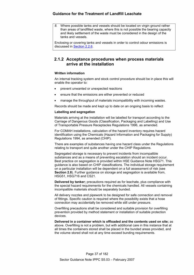
Guidance for the Treatment of Landfill Leachate
Page 37 of 182
Sector Guidance Note IPPC S5.03 – February 2007
8. Where possible tanks and vessels should be located on virgin ground ratherthan areas of landfilled waste, where this is not possible the bearing capacityand likely settlement of the waste must be considered in the design of thetanks and vessels.
Enclosing or covering tanks and vessels in order to control odour emissions isdiscussed in Section 2.2.6.
2.1.2 Acceptance procedures when process materials arrive at the installation
Written information
An internal tracking system and stock control procedure should be in place this willenable the operator to:
• prevent unwanted or unexpected reactions
• ensure that the emissions are either prevented or reduced
• manage the throughput of materials incompatibility with incoming wastes.
Records should be made and kept up to date on an ongoing basis to reflect
Labelling and segregation
Materials arriving at the installation will be labelled for transport according to theCarriage of Dangerous Goods (Classification, Packaging and Labelling) and Useof Transportable Pressure Receptacles Regulations 1996, as amended.
For COMAH installations, calculation of the hazard inventory requires hazardidentification using the Chemicals (Hazard Information and Packaging for Supply)Regulations 1994, as amended (CHIP).
There are examples of substances having one hazard class under the Regulationsrelating to transport and quite another under the CHIP Regulations.
Segregated storage is necessary to prevent incidents from incompatiblesubstances and as a means of preventing escalation should an incident occur.Best practice on segregation is provided within HSE Guidance Note HSG71. Thisguidance is also based on CHIP classifications. The individual storage requirementon a particular installation will be dependent on a full assessment of risk (seeSection 2.8). Further guidance on storage and segregation is available from,HSG51, HSG716 and CS21.
Delivered by tanker; precautions required as for leachate, plus compliance withthe special hazard requirements for the chemicals handled. All vessels containingincompatible materials should be separately bunded.
All delivery nozzles and pipework to be designed for safe connection and removalof fittings. Specific caution is required where the possibility exists that a hoseconnection may accidentally be removed while still under pressure.
Overfilling precautions shall be considered and suitable provision for overfillingprevention provided by method statement or installation of suitable protectiondevices.
Delivered in a container which is offloaded and the contents used on site; asabove. Overfilling is not a problem, but with additional care in this instance that atall times the containers stored shall be placed in the bunded areas provided, andthe volume stored shall not at any time exceed bunding requirements.
Guidance for the Treatment of Landfill Leachate
Page 38 of 182
Sector Guidance Note IPPC S5.03 – February 2007
Indicative BAT requirements for acceptance procedures whentreatment chemicals arrive at the installation1. On arrival loads should:
not be accepted into site unless sufficient storage capacity exists
have all documents checked and approved, and any discrepancies resolvedbefore the material is accepted, and
have any labelling that does not relate to the contents of the drum removed.
2. Appropriate designated storage must be provided, ensuring that all drums andcontainers are correctly labelled and that non-compatible materials aresegregated.
3. Vessels/tanks should be secondary contained or be located aboveground on animpervious surface that is resistant to the chemical being stored, with sealedconstruction joints within a bunded area.
4. Drums should be stored in separate bunded areas that ensure non-compatiblematerials cannot come into contact.
5. All bunds shall:
Have a capacity at least 110% of the largest vessel or drum or 25% of the total tankage volume, which ever is the greater.
Be regularly inspected to ensure that bunds filled by rainwater are regularly emptied – otherwise the purpose of the bunding provided is lost.
Have connections and fill points within the bunded area and no pipework should penetrate the bund wall.
6. Appropriate training should be provided to operatives on the safe handling, useand disposal of process chemicals.
7. Spill kits should be provided in areas of chemical handling and storage andoperatives should be trained in their use. This training should includeappropriate measures e.g. dilution adsorption neutralisation etc.
Guidance for the Treatment of Landfill Leachate
Page 39 of 182
Sector Guidance Note IPPC S5.03 – February 2007
2.1.3 Physical treatment processes
2.1.3.1 Air stripping
2.1.3.1.1 Methane stripping
General information
Methane is more soluble in water than oxygen. At 20°C, about 25mg ofmethane will dissolve in a litre of water, from a pure methane atmosphere.Leachates from within a biologically active landfill will generally be extractedfrom a gaseous environment comprising typically 60 percent methane, and 40percent carbon dioxide (by volume). In these circumstances, at temperatures ofbetween 40 and 20 degrees centigrade, methane can dissolve to concentrationsof between 10 and 15 mg/l. Such dissolved methane concentrations areroutinely measured in landfill leachates (e.g. Robinson et. al., 1999). Even atlandfills where relatively diluted leachates are collected from surface seepages,perimeter ditches etc, concentrations of methane in the order of 2 – 5 mg/l areoften determined, and values can vary widely on a day-to-day basis. Significantmethane levels can even be measured in pools of surface water on cappedlandfill areas, where landfill gas is escaping by bubbling through them.
A concentration of dissolved methane as low as 1.4 mg/l is known to be capableof giving rise to an explosive level of methane gas, in confined atmospheres incontact with such liquid (Buswell and Larson 1937; Larson, 1938). Althoughthere has not been any reported incident of such an explosion within any UKsewer, and actual (as opposed to potential) risks have not been established,there is now a presumption that measures should be applied to control levels ofdissolved methane in discharges of leachate into the public sewerage system.Therefore, in accordance with mine safety procedures, a factor of safety of tentimes is increasingly being applied by regulators to discharges of leachate intothe public sewerage system, and a consent limit of 0.14 mg/l of dissolvedmethane is widely applied by receiving sewerage authorities.
In order to meet this consent limit, therefore, from initial dissolved methanelevels of 15 mg/l in leachates, more than 99 percent removal must be achieved,reliably and consistently.
Process overview
The partition of methane between dissolved and gaseous phases is governedby Henry’s Law. Therefore, removal of methane gas from solution using thepassage of air bubbles through the leachate will operate on a half-life principle.That is, passage of a given volume of air through a given volume of leachate,will reduce concentrations of dissolved methane by a fixed proportion. As such,it will prove very difficult, or very expensive, to achieve required overallpercentage removal of methane within a single stripping reactor, especially ifthis is operated on a continuous flow basis. Detailed trials reported using anumber of leachates from throughout the UK and Ireland (Robinson et. al.,1999) have demonstrated that 3 or 4 reactors, operating in series, will provideoptimum performance (see Figure 2.1 below). A small, non-aerated, finalvessel can provide additional methane removal, by allowing release of micro-bubbles of methane, prior to release of effluent to sewer. Plate 2.1 shows atypical methane stripping system in operation on a landfill site, capable oftreating up to 300 m3/d of leachate.
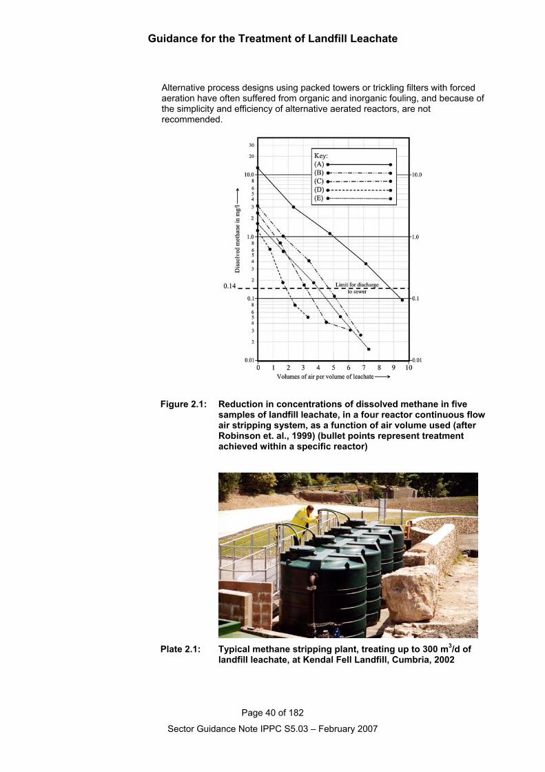
Guidance for the Treatment of Landfill Leachate
Page 40 of 182
Sector Guidance Note IPPC S5.03 – February 2007
Alternative process designs using packed towers or trickling filters with forcedaeration have often suffered from organic and inorganic fouling, and because ofthe simplicity and efficiency of alternative aerated reactors, are notrecommended.
Figure 2.1: Reduction in concentrations of dissolved methane in fivesamples of landfill leachate, in a four reactor continuous flowair stripping system, as a function of air volume used (afterRobinson et. al., 1999) (bullet points represent treatmentachieved within a specific reactor)
Plate 2.1: Typical methane stripping plant, treating up to 300 m3/d oflandfill leachate, at Kendal Fell Landfill, Cumbria, 2002
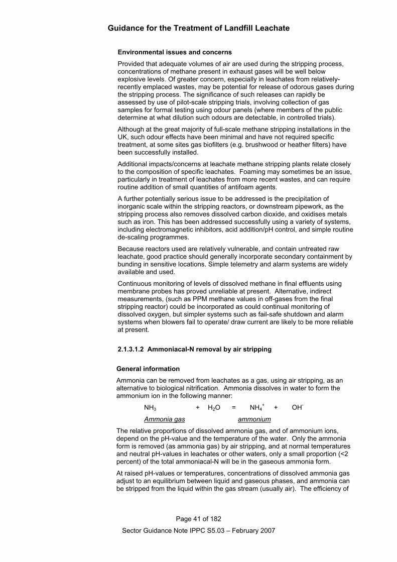
Guidance for the Treatment of Landfill Leachate
Page 41 of 182
Sector Guidance Note IPPC S5.03 – February 2007
Environmental issues and concerns
Provided that adequate volumes of air are used during the stripping process,concentrations of methane present in exhaust gases will be well belowexplosive levels. Of greater concern, especially in leachates from relatively-recently emplaced wastes, may be potential for release of odorous gases duringthe stripping process. The significance of such releases can rapidly beassessed by use of pilot-scale stripping trials, involving collection of gassamples for formal testing using odour panels (where members of the publicdetermine at what dilution such odours are detectable, in controlled trials).
Although at the great majority of full-scale methane stripping installations in theUK, such odour effects have been minimal and have not required specifictreatment, at some sites gas biofilters (e.g. brushwood or heather filters) havebeen successfully installed.
Additional impacts/concerns at leachate methane stripping plants relate closelyto the composition of specific leachates. Foaming may sometimes be an issue,particularly in treatment of leachates from more recent wastes, and can requireroutine addition of small quantities of antifoam agents.
A further potentially serious issue to be addressed is the precipitation ofinorganic scale within the stripping reactors, or downstream pipework, as thestripping process also removes dissolved carbon dioxide, and oxidises metalssuch as iron. This has been addressed successfully using a variety of systems,including electromagnetic inhibitors, acid addition/pH control, and simple routinede-scaling programmes.
Because reactors used are relatively vulnerable, and contain untreated rawleachate, good practice should generally incorporate secondary containment bybunding in sensitive locations. Simple telemetry and alarm systems are widelyavailable and used.
Continuous monitoring of levels of dissolved methane in final effluents usingmembrane probes has proved unreliable at present. Alternative, indirectmeasurements, (such as PPM methane values in off-gases from the finalstripping reactor) could be incorporated as could continual monitoring ofdissolved oxygen, but simpler systems such as fail-safe shutdown and alarmsystems when blowers fail to operate/ draw current are likely to be more reliableat present.
2.1.3.1.2 Ammoniacal-N removal by air stripping
General information
Ammonia can be removed from leachates as a gas, using air stripping, as analternative to biological nitrification. Ammonia dissolves in water to form theammonium ion in the following manner:
NH3 + H2O = NH4+ + OH-
Ammonia gas ammonium
The relative proportions of dissolved ammonia gas, and of ammonium ions,depend on the pH-value and the temperature of the water. Only the ammoniaform is removed (as ammonia gas) by air stripping, and at normal temperaturesand neutral pH-values in leachates or other waters, only a small proportion (<2percent) of the total ammoniacal-N will be in the gaseous ammonia form.
At raised pH-values or temperatures, concentrations of dissolved ammonia gasadjust to an equilibrium between liquid and gaseous phases, and ammonia canbe stripped from the liquid within the gas stream (usually air). The efficiency of
Guidance for the Treatment of Landfill Leachate
Page 42 of 182
Sector Guidance Note IPPC S5.03 – February 2007
the process is increased significantly by increasing values of pH or temperature,and with increasing efficiency the quantity of air required will decrease, and theconcentration of ammonia gas in the exhaust air increases. Typically, either pH-values in excess of 10.0, or temperatures in the order of 60-70°C, are needed toachieve greater than 80 percent of ammoniacal-N in the gaseous ammoniaphase, to provide an efficient removal process.
Unlike many other treatment processes, the required air volume removes aconstant percentage of the incoming ammonia, regardless of influentconcentrations in leachate, the progressive removal of ammoniacal-N thereforeoperating in a “half-life” manner. This has two consequences – first, at veryhigh concentrations of ammoniacal-N, the stripping process is increasingly cost-effective; and second, it becomes difficult or costly to achieve low effluentconcentrations of ammoniacal-N, such as below 50 or 100 mg/l. On this basis,ammonia stripping will generally only prove to be cost-effective, where partialpre-treatment is required, for example, prior to discharge into the public sewer,or before further removal of ammoniacal-N in a subsequent stage of biologicaltreatment.
In achieving relatively low effluent values of ammoniacal-N (e.g. <50 mg/l), verylarge volumes of air will be required and this generally makes air strippinguncompetitive in cost terms for such applications.
Process overview
Ammonia stripping can be carried out in tanks or lagoons, packed towers, or incounter-current, multi-stage reactors. A consequence of optimisation of theprocess, to achieve reduced aeration requirements, is that air containing highconcentrations of ammonia gas (to tens of grammes per cubic metre, equivalentto 10 percent by volume), can be released. This is likely to cause unacceptablehealth hazards at most sites, and must therefore be controlled. One optionwould be absorption of the ammonia in sulphuric acid, to produce ammoniumsulphate, which may have potential for use as an agricultural fertiliser. Anotherpossible solution is thermal destruction of the ammonia to nitrogen gas, ideallywithin a high efficiency landfill gas flare.
Few full-scale ammonia stripping systems have been installed for treatment ofleachates at UK landfill sites. A few based on alkali dosing have failed, orrapidly been abandoned, as a result of environmental impact, operationaldifficulties or excessive cost of reagents. At least one plant in the UK plant usesleachate heating to enhance the stripping of ammonia. In recent years thistechnology has become established as a pre-treatment step for leachates inHong Kong, from some of the largest landfill sites in the World (e.g. see Eden,2001).
At three initial sites where such systems were installed in Hong Kong, leachateflows were typically in the range 720-1800 m3/d, and concentrations ofammoniacal-N of 6700 mg/l in leachate were used for design purposes. Theplants could efficiently remove these high concentrations of ammoniacal-Ndown to below 100 mg/l, before subsequent biological treatment of effluent insequencing batch reactor (SBR) plants. Landfill gas was used to raise leachatetemperatures to 70°C before passage to the stripping tower, and effectivethermal destruction of ammonia gas (>99.99 percent) has been achieved withinthe landfill gas flare.
Environmental issues and concerns
Although ammonia stripping can be an effective and cost-effective treatmentprocess for large volumes of very strong landfill leachate, application for use ona smaller scale at UK landfills is limited.
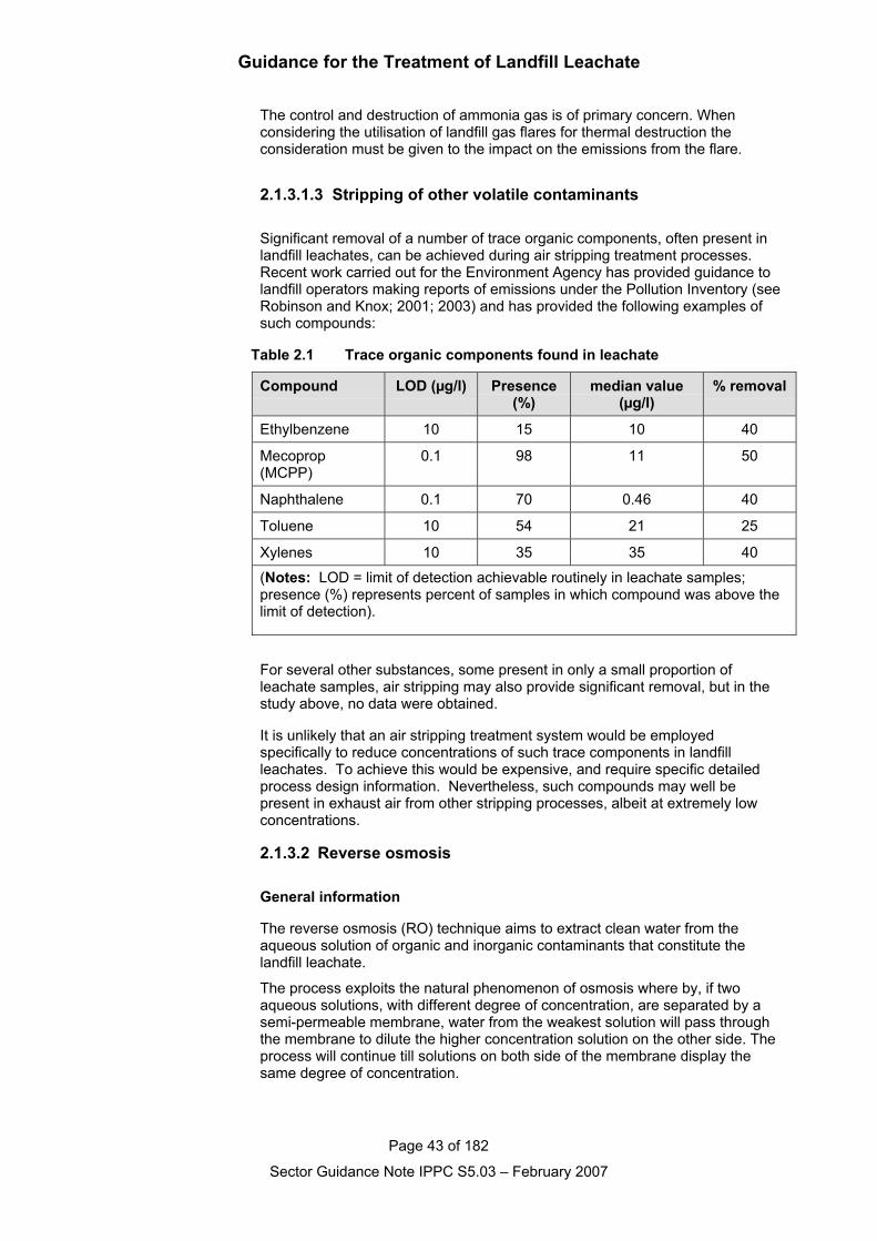
Guidance for the Treatment of Landfill Leachate
Page 43 of 182
Sector Guidance Note IPPC S5.03 – February 2007
The control and destruction of ammonia gas is of primary concern. Whenconsidering the utilisation of landfill gas flares for thermal destruction theconsideration must be given to the impact on the emissions from the flare.
2.1.3.1.3 Stripping of other volatile contaminants
Significant removal of a number of trace organic components, often present inlandfill leachates, can be achieved during air stripping treatment processes.Recent work carried out for the Environment Agency has provided guidance tolandfill operators making reports of emissions under the Pollution Inventory (seeRobinson and Knox; 2001; 2003) and has provided the following examples ofsuch compounds:
Table 2.1 Trace organic components found in leachate
Compound LOD (µg/l) Presence(%)
median value(µg/l)
% removal
Ethylbenzene 10 15 10 40
Mecoprop(MCPP)
0.1 98 11 50
Naphthalene 0.1 70 0.46 40
Toluene 10 54 21 25
Xylenes 10 35 35 40
(Notes: LOD = limit of detection achievable routinely in leachate samples;presence (%) represents percent of samples in which compound was above thelimit of detection).
For several other substances, some present in only a small proportion ofleachate samples, air stripping may also provide significant removal, but in thestudy above, no data were obtained.
It is unlikely that an air stripping treatment system would be employedspecifically to reduce concentrations of such trace components in landfillleachates. To achieve this would be expensive, and require specific detailedprocess design information. Nevertheless, such compounds may well bepresent in exhaust air from other stripping processes, albeit at extremely lowconcentrations.
2.1.3.2 Reverse osmosis
General information
The reverse osmosis (RO) technique aims to extract clean water from theaqueous solution of organic and inorganic contaminants that constitute thelandfill leachate.
The process exploits the natural phenomenon of osmosis where by, if twoaqueous solutions, with different degree of concentration, are separated by asemi-permeable membrane, water from the weakest solution will pass throughthe membrane to dilute the higher concentration solution on the other side. Theprocess will continue till solutions on both side of the membrane display thesame degree of concentration.
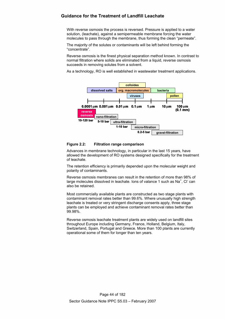
Guidance for the Treatment of Landfill Leachate
Page 44 of 182
Sector Guidance Note IPPC S5.03 – February 2007
With reverse osmosis the process is reversed. Pressure is applied to a watersolution, (leachate), against a semipermeable membrane forcing the watermolecules to pass through the membrane, thus forming the clean “permeate”.
The majority of the solutes or contaminants will be left behind forming the“concentrate”.
Reverse osmosis is the finest physical separation method known. In contrast tonormal filtration where solids are eliminated from a liquid, reverse osmosissucceeds in removing solutes from a solvent.
As a technology, RO is well established in wastewater treatment applications.
pollen
bacteria
viruses
org. macromolecules
colloides
dissolved salts
gravel-filtration
micro-filtration0.2-5 bar
ultra-filtration1-10 bar
reverseosmosis
10-120 barnano-filtration5-10 bar
0.0001 µm 0.001 µm 0.1 µm0.01 µm 10 µm1 µm 100 µm(0.1 mm)
pollen
bacteria
viruses
org. macromolecules
colloides
dissolved salts
gravel-filtration
micro-filtration0.2-5 bar
ultra-filtration1-10 bar
reverseosmosis
10-120 barnano-filtration5-10 bar
0.0001 µm 0.001 µm 0.1 µm0.01 µm 10 µm1 µm 100 µm(0.1 mm)
0.0001 µm 0.001 µm 0.1 µm0.01 µm 10 µm1 µm 100 µm(0.1 mm)
Figure 2.2: Filtration range comparison
Advances in membrane technology, in particular in the last 15 years, haveallowed the development of RO systems designed specifically for the treatmentof leachate.
The retention efficiency is primarily depended upon the molecular weight andpolarity of contaminants.
Reverse osmosis membranes can result in the retention of more than 98% oflarge molecules dissolved in leachate. Ions of valance 1 such as Na+, Cl- canalso be retained.
Most commercially available plants are constructed as two stage plants withcontaminant removal rates better than 99.6%. Where unusually high strengthleachate is treated or very stringent discharge consents apply, three stageplants can be employed and achieve contaminant removal rates better than99.98%.
Reverse osmosis leachate treatment plants are widely used on landfill sitesthroughout Europe including Germany, France, Holland, Belgium, Italy,Switzerland, Spain, Portugal and Greece. More than 100 plants are currentlyoperational some of them for longer than ten years.
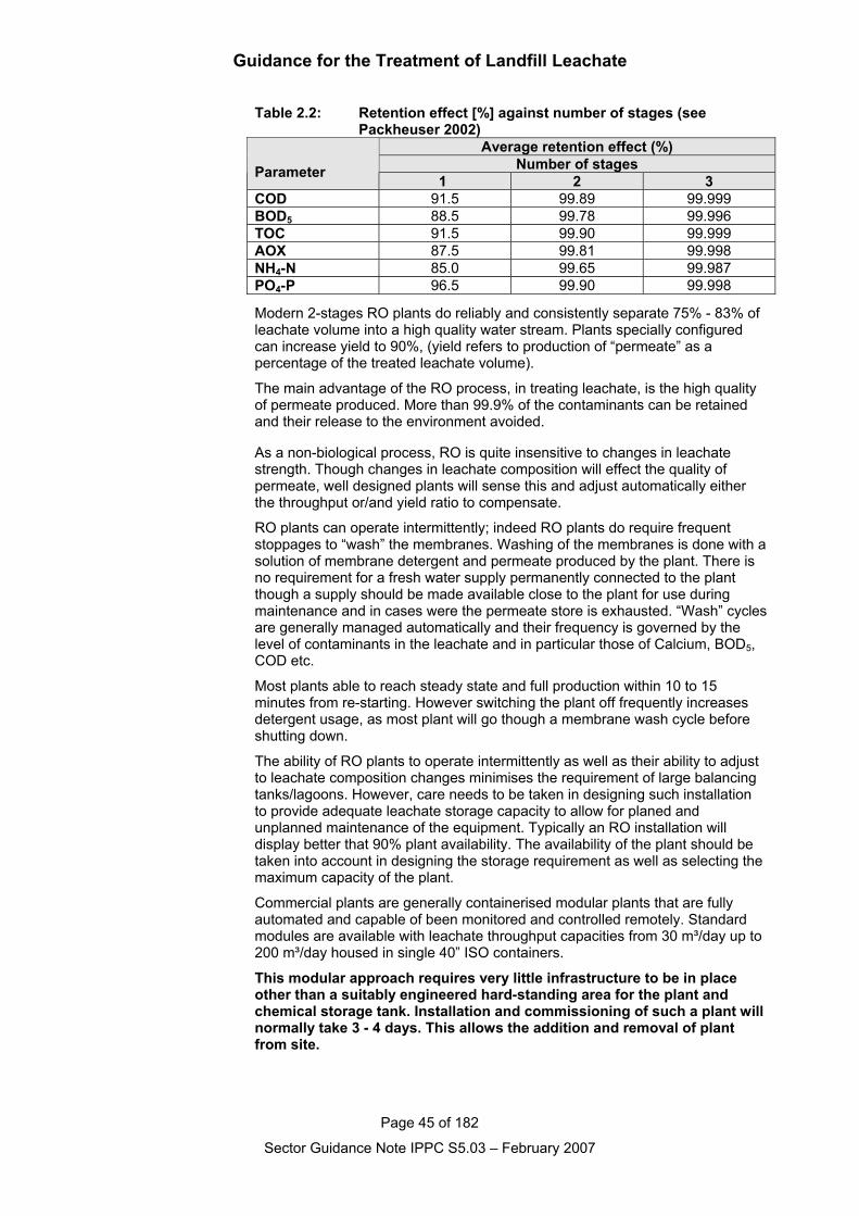
Guidance for the Treatment of Landfill Leachate
Page 45 of 182
Sector Guidance Note IPPC S5.03 – February 2007
Table 2.2: Retention effect [%] against number of stages (see Packheuser 2002)
Average retention effect (%)Number of stagesParameter 1 2 3
COD 91.5 99.89 99.999BOD5 88.5 99.78 99.996TOC 91.5 99.90 99.999AOX 87.5 99.81 99.998NH4-N 85.0 99.65 99.987PO4-P 96.5 99.90 99.998
Modern 2-stages RO plants do reliably and consistently separate 75% - 83% ofleachate volume into a high quality water stream. Plants specially configuredcan increase yield to 90%, (yield refers to production of “permeate” as apercentage of the treated leachate volume).
The main advantage of the RO process, in treating leachate, is the high qualityof permeate produced. More than 99.9% of the contaminants can be retainedand their release to the environment avoided.
As a non-biological process, RO is quite insensitive to changes in leachatestrength. Though changes in leachate composition will effect the quality ofpermeate, well designed plants will sense this and adjust automatically eitherthe throughput or/and yield ratio to compensate.
RO plants can operate intermittently; indeed RO plants do require frequentstoppages to “wash” the membranes. Washing of the membranes is done with asolution of membrane detergent and permeate produced by the plant. There isno requirement for a fresh water supply permanently connected to the plantthough a supply should be made available close to the plant for use duringmaintenance and in cases were the permeate store is exhausted. “Wash” cyclesare generally managed automatically and their frequency is governed by thelevel of contaminants in the leachate and in particular those of Calcium, BOD5,COD etc.
Most plants able to reach steady state and full production within 10 to 15minutes from re-starting. However switching the plant off frequently increasesdetergent usage, as most plant will go though a membrane wash cycle beforeshutting down.
The ability of RO plants to operate intermittently as well as their ability to adjustto leachate composition changes minimises the requirement of large balancingtanks/lagoons. However, care needs to be taken in designing such installationto provide adequate leachate storage capacity to allow for planed andunplanned maintenance of the equipment. Typically an RO installation willdisplay better that 90% plant availability. The availability of the plant should betaken into account in designing the storage requirement as well as selecting themaximum capacity of the plant.
Commercial plants are generally containerised modular plants that are fullyautomated and capable of been monitored and controlled remotely. Standardmodules are available with leachate throughput capacities from 30 m³/day up to200 m³/day housed in single 40” ISO containers.
This modular approach requires very little infrastructure to be in placeother than a suitably engineered hard-standing area for the plant andchemical storage tank. Installation and commissioning of such a plant willnormally take 3 - 4 days. This allows the addition and removal of plantfrom site.
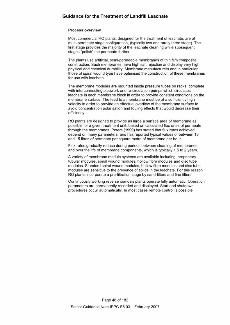
Guidance for the Treatment of Landfill Leachate
Page 46 of 182
Sector Guidance Note IPPC S5.03 – February 2007
Process overview
Most commercial RO plants, designed for the treatment of leachate, are ofmulti-permeate stage configuration, (typically two and rarely three stage). Thefirst stage provides the majority of the leachate cleaning while subsequentstages “polish” the permeate further.
The plants use artificial, semi-permeable membranes of thin film compositeconstruction. Such membranes have high salt rejection and display very highphysical and chemical durability. Membrane manufacturers and in particularthose of spiral wound type have optimised the construction of these membranesfor use with leachate.
The membrane modules are mounted inside pressure tubes on racks, completewith interconnecting pipework and re-circulation pumps which circulatesleachate in each membrane block in order to provide constant conditions on themembrane surface. The feed to a membrane must be of a sufficiently highvelocity in order to provide an effectual overflow of the membrane surface toavoid concentration polarisation and fouling effects that would decrease theirefficiency.
RO plants are designed to provide as large a surface area of membrane aspossible for a given treatment unit, based on calculated flux rates of permeatethrough the membranes. Peters (1999) has stated that flux rates achieveddepend on many parameters, and has reported typical values of between 13and 15 litres of permeate per square metre of membrane per hour.
Flux rates gradually reduce during periods between cleaning of membranes,and over the life of membrane components, which is typically 1.5 to 2 years.
A variety of membrane module systems are available including; proprietarytubular modules, spiral wound modules, hollow fibre modules and disc tubemodules. Standard spiral wound modules, hollow fibre modules and disc tubemodules are sensitive to the presence of solids in the leachate. For this reasonRO plants incorporate a pre-filtration stage by sand-filters and fine filters.
Continuously working reverse osmosis plants operate fully automatic. Operationparameters are permanently recorded and displayed. Start and shutdownprocedures occur automatically. In most cases remote control is possible
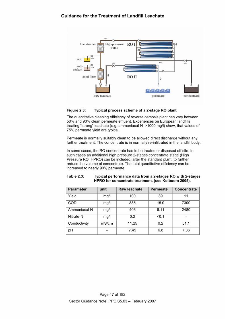
Guidance for the Treatment of Landfill Leachate
Page 47 of 182
Sector Guidance Note IPPC S5.03 – February 2007
Figure 2.3: Typical process scheme of a 2-stage RO plant
The quantitative cleaning efficiency of reverse osmosis plant can vary between50% and 90% clean permeate effluent. Experiences on European landfillstreating “strong” leachate (e.g. ammoniacal-N >1000 mg/l) show, that values of75% permeate yield are typical.
Permeate is normally suitably clean to be allowed direct discharge without anyfurther treatment. The concentrate is in normally re-infiltrated in the landfill body.
In some cases, the RO concentrate has to be treated or disposed off site. Insuch cases an additional high pressure 2-stages concentrate stage (HighPressure RO, HPRO) can be included, after the standard plant, to furtherreduce the volume of concentrate. The total quantitative efficiency can beincreased to nearly 90% permeate.
Table 2.3: Typical performance data from a 2-stages RO with 2-stagesHPRO for concentrate treatment. (see Kolboom 2005).
Parameter unit Raw leachate Permeate Concentrate
Yield mg/l 100 89 11
COD mg/l 835 15.0 7300
Ammoniacal-N mg/l 406 6.11 2480
Nitrate-N mg/l 0.2 <0.1 -
Conductivity mS/cm 11.25 0.2 51.1
pH - 7.45 6.8 7.36
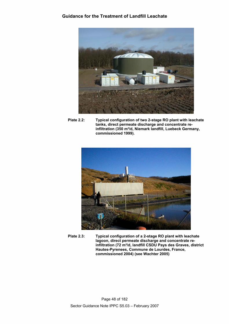
Guidance for the Treatment of Landfill Leachate
Page 48 of 182
Sector Guidance Note IPPC S5.03 – February 2007
Plate 2.2: Typical configuration of two 2-stage RO plant with leachatetanks, direct permeate discharge and concentrate re-infiltration (350 m³/d, Niemark landfill, Luebeck Germany, commissioned 1999).
Plate 2.3: Typical configuration of a 2-stage RO plant with leachate lagoon, direct permeate discharge and concentrate re-infiltration (72 m³/d, landfill CSDU Pays des Graves, districtHautes-Pyrenees, Commune de Lourdes, France, commissioned 2004) (see Wachter 2005)
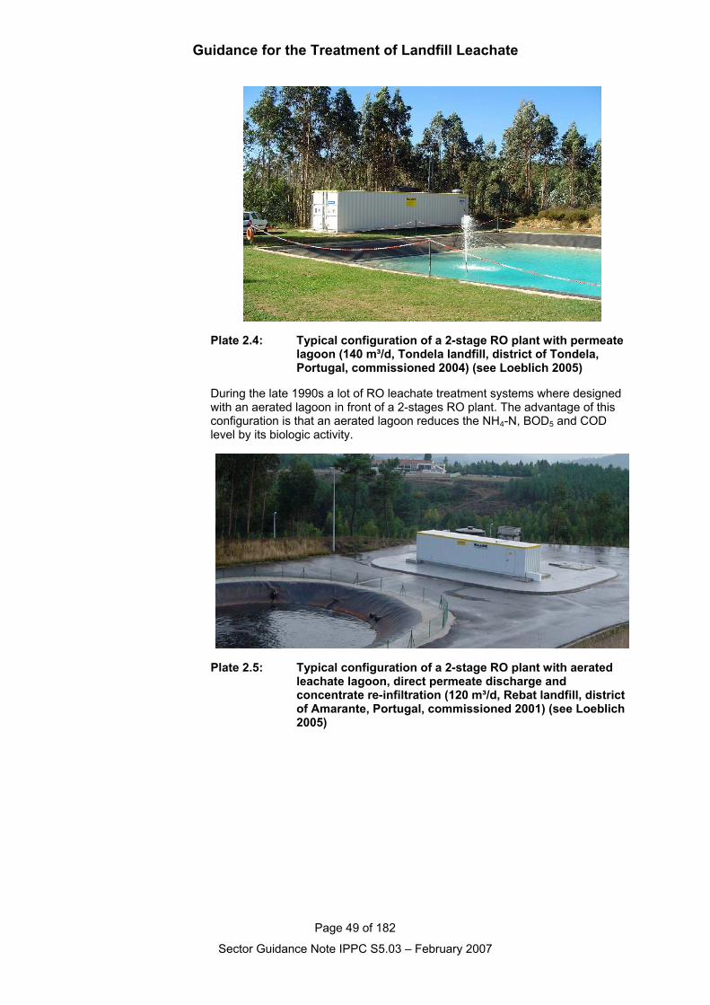
Guidance for the Treatment of Landfill Leachate
Page 49 of 182
Sector Guidance Note IPPC S5.03 – February 2007
Plate 2.4: Typical configuration of a 2-stage RO plant with permeate lagoon (140 m³/d, Tondela landfill, district of Tondela, Portugal, commissioned 2004) (see Loeblich 2005)
During the late 1990s a lot of RO leachate treatment systems where designedwith an aerated lagoon in front of a 2-stages RO plant. The advantage of thisconfiguration is that an aerated lagoon reduces the NH4-N, BOD5 and CODlevel by its biologic activity.
Plate 2.5: Typical configuration of a 2-stage RO plant with aerated leachate lagoon, direct permeate discharge and concentrate re-infiltration (120 m³/d, Rebat landfill, district of Amarante, Portugal, commissioned 2001) (see Loeblich 2005)
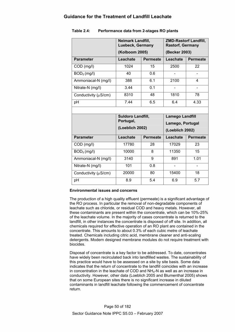
Guidance for the Treatment of Landfill Leachate
Page 50 of 182
Sector Guidance Note IPPC S5.03 – February 2007
Table 2.4: Performance data from 2-stages RO plants
Environmental issues and concerns
The production of a high quality effluent (permeate) is a significant advantage ofthe RO process. In particular the removal of non-degradable components ofleachate such as chloride, or residual COD and heavy metals. However, allthese contaminants are present within the concentrate, which can be 10%-25%of the leachate volume. In the majority of cases concentrate is returned to thelandfill, in other instances the concentrate is disposed of off site. In addition, allchemicals required for effective operation of an RO plant are contained in theconcentrate. This amounts to about 0.3% of each cubic metre of leachatetreated. Chemicals including citric acid, membrane cleaner and anti-scalingdetergents. Modern designed membrane modules do not require treatment withbiocides.
Disposal of concentrate is a key factor to be addressed. To date, concentrateshave widely been recirculated back into landfilled wastes. The sustainability ofthis practice would have to be assessed on a site by site basis. Some dataindicates that the return of concentrate to the landfill coincides with an increasein concentration in the leachate of COD and NH4-N as well as an increase inconductivity. However, other data (Loeblich 2005 and Blumenthal 2005) showsthat on some European sites there is no significant increase in dilutedcontaminants in landfill leachate following the commencement of concentratereturn.
Neimark Landfill,Luebeck, Germany
(Kolboom 2005)
ZMD-Rastorf Landfill,Rastorf, Germany
(Becker 2003)
Parameter Leachate Permeate Leachate Permeate
COD (mg/l) 1024 15 2500 22
BOD5 (mg/l) 40 0.6 - -
Ammoniacal-N (mg/l) 388 6.1 2100 4
Nitrate-N (mg/l) 3.44 0.1 - -
Conductivity (µS/cm) 8310 48 1810 78
pH 7.44 6.5 6.4 4.33
Suldoro Landfill,Portugal,
(Loeblich 2002)
Lamego Landfill
Lamego, Portugal
(Loeblich 2002)
Parameter Leachate Permeate Leachate Permeate
COD (mg/l) 17780 28 17029 23
BOD5 (mg/l) 10000 8 11350 15
Ammoniacal-N (mg/l) 3140 9 891 1.01
Nitrate-N (mg/l) 101 0.8 - -
Conductivity (µS/cm) 20000 80 15400 18
pH 8.9 5.4 6.9 5.7
Guidance for the Treatment of Landfill Leachate
Page 51 of 182
Sector Guidance Note IPPC S5.03 – February 2007
When considering the sustainability of the return of concentrate to the landfill:- any predicted change in leachate concentration should be assessed;- it must be shown that the landfill is adequately engineered so that the
concentrate does not cause pollution (particular attention should be given tothe impact on groundwater);
- it must be shown that the leachate treatment system can adequately treatany predicted change in leachate quality resulting from the return of theconcentrate; and
- chemicals essential to the effective operation of the plant should beselected so as not to compromise the disposal of the concentrate.
Secondary concentrate treatment processes, such as evaporation and dryers,have been used to reduce volumes further in countries such as Germany, theNetherlands, Belgium, France, Portugal, Spain (where RO plants are mostwidely used for leachate treatment), the residues from these processes havebeen stored in barrels within old mines. Since most of the solid material isreadily soluble, highly engineered containment is required indefinitely. Most ofthe leachate dryers are out of operation now.Reverse osmosis systems have also been used to treat leachates from landfillsthat have received residues from MSW incinerators. Hanashima et. al. (1999)reported RO tests using disc tube modules at one such site. Althoughleachates contained concentrations of chloride above 6000 mg/l, 95 percentpermeate recovery was reported, and concentrations of dioxins were alsoreduced by up to 99.8 percent.
Guidance for the Treatment of Landfill Leachate
Page 52 of 182
Sector Guidance Note IPPC S5.03 – February 2007
2.1.3.3 Solids removalIt may be necessary to remove solids from either raw leachates or from pre–treated leachates prior to disposal. Processes most commonly used includesedimentation/settlement, sand filtration, dissolved air flotation or membranefiltration.
2.1.3.3.1 Sedimentation and settlement
Provision of sedimentation or solids settlement stages for pre-treatment for rawleachates is rarely appropriate, and there are very few situations in the UKwhere such facilities have been used.
Use of coagulation and flocculation processes, not only to reduce levels ofsuspended solids in leachates, but to provide additional removal of colloidal andother contaminants, is discussed separately below.
An efficient sedimentation/settlement stage of treatment is essential to achieveadequate clarification of effluents following biological treatment of leachates,and these issues are considered separately within that section.
2.1.3.3.2 Sand filtration
General information
Sand filtration involves the passage of the effluent through a high quality sandmedia with a specific particle size range between 0.8-1.7mm. The application ofsand filtration processes of any sort to raw leachates will rarely be appropriate.Operational difficulties such as generation of biological sludges, or ofuncontrolled partial biological processes, might potentially cause greatdifficulties.
Nevertheless, the use of tertiary sand filtration processes can make a significantimprovement to the quality of effluents from biological stages of treatment, notonly in terms of concentrations of suspended solids, but also of other associatedcontaminants (e.g. BOD5, COD, iron).
Although continuous backwash sand filters are in use world wide, they have todate only occasionally been applied to treatment of leachate. There have beena few applications in the UK, where they have been specified for polishing ofbiologically pre-treated leachates, and in appropriate circumstances they havegreat potential for this purpose
Units have the advantage that they are generally transportable, and can readilybe trialled or used on a temporary basis. They are relatively simple inoperation, and lend themselves well to automation and telemetry/failsafeprogramming. On the other hand, they can be relatively expensive per kg ofsolids removed basis, and their height (typically 8m or more) may sometimescause planning difficulties.
Process overview
Fixed bed sand filters, where a media (usually graded sand) traps and removessuspended solids from water passing through the media, may operate usinggravity to drive water downwards, or by means of pressure applied from apump. For both types of filter, the bed builds up head loss over time, as solidsaccumulate within it. When this pressure head loss becomes unacceptable, assolids are progressively entrained within the sand media, the filter needs to be
Guidance for the Treatment of Landfill Leachate
Page 53 of 182
Sector Guidance Note IPPC S5.03 – February 2007
backwashed, by reversing the flow of water to an upward direction. Backwashwater (generally, treated effluent is used), sometimes using air to agitate thesand media, with addition of chemicals and released particles are usuallydischarged into a balancing tank, or may be returned into the original biologicaltreatment process. Backwashing is automatically controlled either by adjustabletimers, or by sensors which detect when the pressure differential exceeds a pre-set value. During the period of backwashing, no effluent can be treated by thebed.
The volume of backwash water produced will be determined by theconcentrations of suspended solids in the feed, to some extent by their nature,and by the concentration of suspended solids required in the effluent. Manyproprietary systems for fixed bed filtration are available, but few have been usedin the UK for either raw leachate pre-treatment, or for final polishing ofbiologically treated effluents.
The resultant final effluent from a sand filtration system can have low levels ofresidual solids, and the application is particularly useful for discharge to river.The interception of solids can also be a useful technique for the removal ofsubstances capable of bioaccumulation, which may be present in biologicalsolids, or in some colloids.
Recently, tertiary treatment of biologically treated leachate has been carried outusing a recovered media made from waste glass, with a particle size range of0.5-1.0mm. The much smoother surface of the recovered glass has enabledthe media to be cleaned more effectively using simple backflushing, and theremoved solids have been returned to the treatment process. This has beenparticularly useful for maintaining nitrifying bacteria in the treatment process,and for the elimination of list 1 substances from the discharge.
An alternative type of sand filter is the moving bed, or continuous backwashfilter, which has been developed into several forms, the most well-known beingthe proprietary “DynaSand®” system, which is currently in use in tens ofthousands of applications Worldwide, since its introduction 2 or 3 decades ago.
The moving bed sand filter operates continuously, avoiding the need for periodicshutdowns to allow the sand to be backwashed, as sand is cleanedcontinuously by means of an internal washing system. The process is based onthe countercurrent principle (see Figure 2.4), with dirty water entering the unit atthe bottom, and travelling upwards, through the downward-moving fluidisedsand bed. Suspended solids are strained from the rising water, by filtration andadsorption.
An airlift pump and draft tube, in the centre of the unit, recirculate sand andfiltered particles from the bottom of the filter to the top of the vessel, which isusually open, into a separation box at the top of the unit. Here sand isseparated from the removed suspended particles by turbulent action, theheavier grains of cleaned sand falling back into the top of the filter, and thelighter solid particles flowing over a weir to waste. As a result, the sand bed isin slow, constant downward motion through the unit, water purification and sandwashing take place continuously, and no moving parts are involved in thesystem. Chemical flocculants (e.g. FeCl3) can sometimes be added to waterbeing treated, to improve the performance of the process.
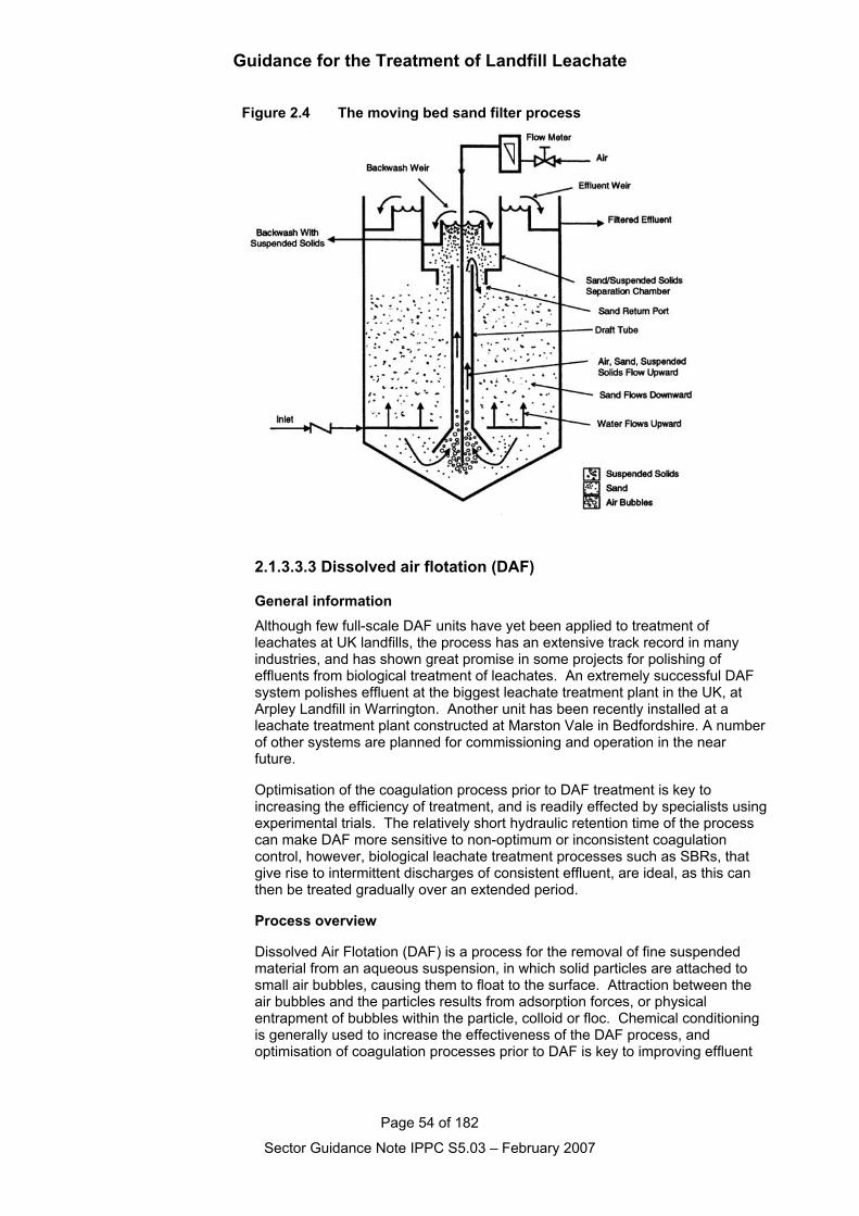
Guidance for the Treatment of Landfill Leachate
Page 54 of 182
Sector Guidance Note IPPC S5.03 – February 2007
Figure 2.4 The moving bed sand filter process
2.1.3.3.3 Dissolved air flotation (DAF)
General informationAlthough few full-scale DAF units have yet been applied to treatment ofleachates at UK landfills, the process has an extensive track record in manyindustries, and has shown great promise in some projects for polishing ofeffluents from biological treatment of leachates. An extremely successful DAFsystem polishes effluent at the biggest leachate treatment plant in the UK, atArpley Landfill in Warrington. Another unit has been recently installed at aleachate treatment plant constructed at Marston Vale in Bedfordshire. A numberof other systems are planned for commissioning and operation in the nearfuture.
Optimisation of the coagulation process prior to DAF treatment is key toincreasing the efficiency of treatment, and is readily effected by specialists usingexperimental trials. The relatively short hydraulic retention time of the processcan make DAF more sensitive to non-optimum or inconsistent coagulationcontrol, however, biological leachate treatment processes such as SBRs, thatgive rise to intermittent discharges of consistent effluent, are ideal, as this canthen be treated gradually over an extended period.
Process overview
Dissolved Air Flotation (DAF) is a process for the removal of fine suspendedmaterial from an aqueous suspension, in which solid particles are attached tosmall air bubbles, causing them to float to the surface. Attraction between theair bubbles and the particles results from adsorption forces, or physicalentrapment of bubbles within the particle, colloid or floc. Chemical conditioningis generally used to increase the effectiveness of the DAF process, andoptimisation of coagulation processes prior to DAF is key to improving effluent
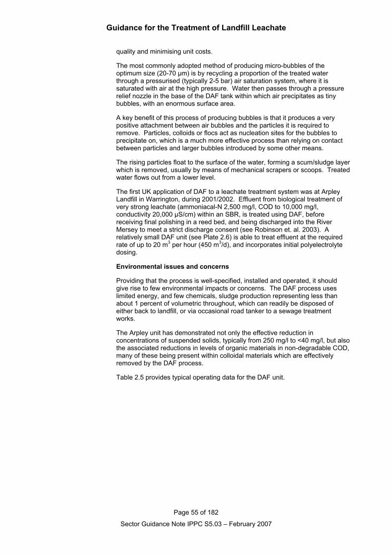
Guidance for the Treatment of Landfill Leachate
Page 55 of 182
Sector Guidance Note IPPC S5.03 – February 2007
quality and minimising unit costs.
The most commonly adopted method of producing micro-bubbles of theoptimum size (20-70 µm) is by recycling a proportion of the treated waterthrough a pressurised (typically 2-5 bar) air saturation system, where it issaturated with air at the high pressure. Water then passes through a pressurerelief nozzle in the base of the DAF tank within which air precipitates as tinybubbles, with an enormous surface area.
A key benefit of this process of producing bubbles is that it produces a verypositive attachment between air bubbles and the particles it is required toremove. Particles, colloids or flocs act as nucleation sites for the bubbles toprecipitate on, which is a much more effective process than relying on contactbetween particles and larger bubbles introduced by some other means.
The rising particles float to the surface of the water, forming a scum/sludge layerwhich is removed, usually by means of mechanical scrapers or scoops. Treatedwater flows out from a lower level.
The first UK application of DAF to a leachate treatment system was at ArpleyLandfill in Warrington, during 2001/2002. Effluent from biological treatment ofvery strong leachate (ammoniacal-N 2,500 mg/l, COD to 10,000 mg/l,conductivity 20,000 µS/cm) within an SBR, is treated using DAF, beforereceiving final polishing in a reed bed, and being discharged into the RiverMersey to meet a strict discharge consent (see Robinson et. al. 2003). Arelatively small DAF unit (see Plate 2.6) is able to treat effluent at the requiredrate of up to 20 m3 per hour (450 m3/d), and incorporates initial polyelectrolytedosing.
Environmental issues and concerns
Providing that the process is well-specified, installed and operated, it shouldgive rise to few environmental impacts or concerns. The DAF process useslimited energy, and few chemicals, sludge production representing less thanabout 1 percent of volumetric throughout, which can readily be disposed ofeither back to landfill, or via occasional road tanker to a sewage treatmentworks.
The Arpley unit has demonstrated not only the effective reduction inconcentrations of suspended solids, typically from 250 mg/l to <40 mg/l, but alsothe associated reductions in levels of organic materials in non-degradable COD,many of these being present within colloidal materials which are effectivelyremoved by the DAF process.
Table 2.5 provides typical operating data for the DAF unit.
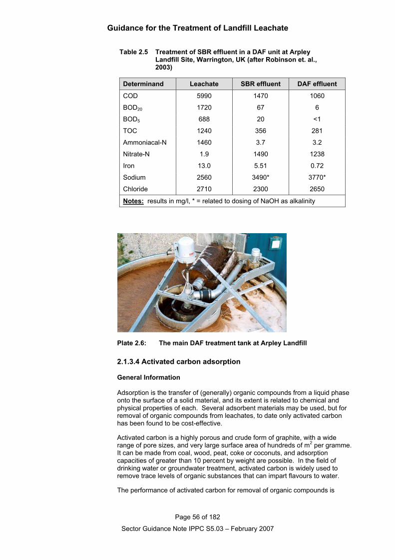
Guidance for the Treatment of Landfill Leachate
Page 56 of 182
Sector Guidance Note IPPC S5.03 – February 2007
Table 2.5 Treatment of SBR effluent in a DAF unit at Arpley Landfill Site, Warrington, UK (after Robinson et. al., 2003)
Determinand Leachate SBR effluent DAF effluent
COD 5990 1470 1060
BOD20 1720 67 6
BOD5 688 20 <1
TOC 1240 356 281
Ammoniacal-N 1460 3.7 3.2
Nitrate-N 1.9 1490 1238
Iron 13.0 5.51 0.72
Sodium 2560 3490* 3770*
Chloride 2710 2300 2650
Notes: results in mg/l, * = related to dosing of NaOH as alkalinity
Plate 2.6: The main DAF treatment tank at Arpley Landfill
2.1.3.4 Activated carbon adsorption
General Information
Adsorption is the transfer of (generally) organic compounds from a liquid phaseonto the surface of a solid material, and its extent is related to chemical andphysical properties of each. Several adsorbent materials may be used, but forremoval of organic compounds from leachates, to date only activated carbonhas been found to be cost-effective.
Activated carbon is a highly porous and crude form of graphite, with a widerange of pore sizes, and very large surface area of hundreds of m2 per gramme.It can be made from coal, wood, peat, coke or coconuts, and adsorptioncapacities of greater than 10 percent by weight are possible. In the field ofdrinking water or groundwater treatment, activated carbon is widely used toremove trace levels of organic substances that can impart flavours to water.
The performance of activated carbon for removal of organic compounds is
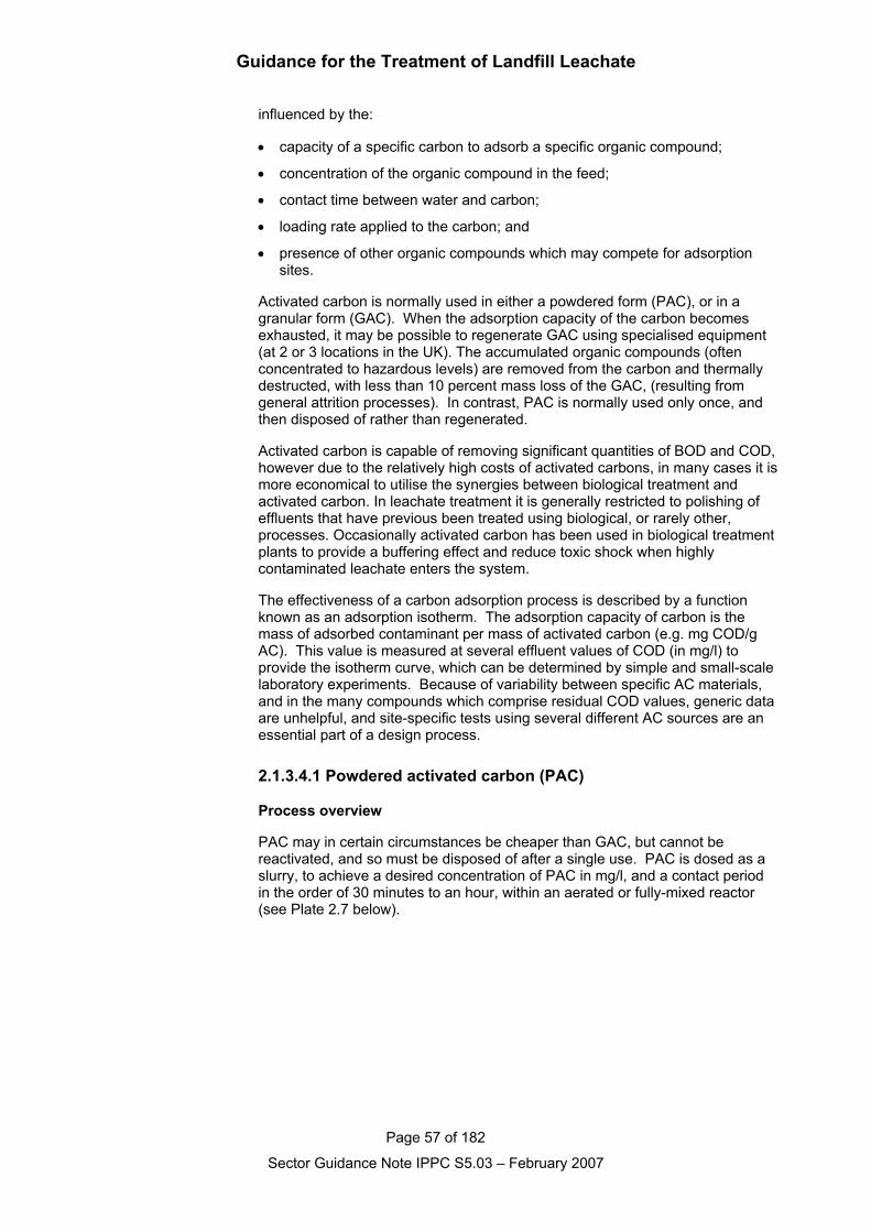
Guidance for the Treatment of Landfill Leachate
Page 57 of 182
Sector Guidance Note IPPC S5.03 – February 2007
influenced by the:
• capacity of a specific carbon to adsorb a specific organic compound;
• concentration of the organic compound in the feed;
• contact time between water and carbon;
• loading rate applied to the carbon; and
• presence of other organic compounds which may compete for adsorptionsites.
Activated carbon is normally used in either a powdered form (PAC), or in agranular form (GAC). When the adsorption capacity of the carbon becomesexhausted, it may be possible to regenerate GAC using specialised equipment(at 2 or 3 locations in the UK). The accumulated organic compounds (oftenconcentrated to hazardous levels) are removed from the carbon and thermallydestructed, with less than 10 percent mass loss of the GAC, (resulting fromgeneral attrition processes). In contrast, PAC is normally used only once, andthen disposed of rather than regenerated.
Activated carbon is capable of removing significant quantities of BOD and COD,however due to the relatively high costs of activated carbons, in many cases it ismore economical to utilise the synergies between biological treatment andactivated carbon. In leachate treatment it is generally restricted to polishing ofeffluents that have previous been treated using biological, or rarely other,processes. Occasionally activated carbon has been used in biological treatmentplants to provide a buffering effect and reduce toxic shock when highlycontaminated leachate enters the system.
The effectiveness of a carbon adsorption process is described by a functionknown as an adsorption isotherm. The adsorption capacity of carbon is themass of adsorbed contaminant per mass of activated carbon (e.g. mg COD/gAC). This value is measured at several effluent values of COD (in mg/l) toprovide the isotherm curve, which can be determined by simple and small-scalelaboratory experiments. Because of variability between specific AC materials,and in the many compounds which comprise residual COD values, generic dataare unhelpful, and site-specific tests using several different AC sources are anessential part of a design process.
2.1.3.4.1 Powdered activated carbon (PAC)
Process overview
PAC may in certain circumstances be cheaper than GAC, but cannot bereactivated, and so must be disposed of after a single use. PAC is dosed as aslurry, to achieve a desired concentration of PAC in mg/l, and a contact periodin the order of 30 minutes to an hour, within an aerated or fully-mixed reactor(see Plate 2.7 below).
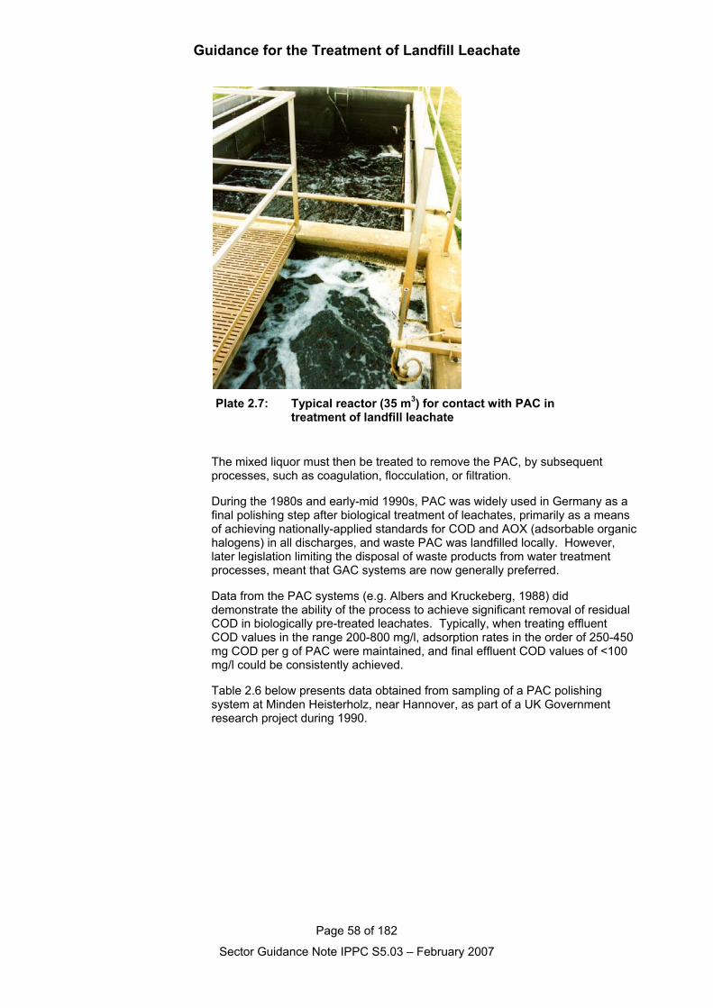
Guidance for the Treatment of Landfill Leachate
Page 58 of 182
Sector Guidance Note IPPC S5.03 – February 2007
Plate 2.7: Typical reactor (35 m3) for contact with PAC intreatment of landfill leachate
The mixed liquor must then be treated to remove the PAC, by subsequentprocesses, such as coagulation, flocculation, or filtration.
During the 1980s and early-mid 1990s, PAC was widely used in Germany as afinal polishing step after biological treatment of leachates, primarily as a meansof achieving nationally-applied standards for COD and AOX (adsorbable organichalogens) in all discharges, and waste PAC was landfilled locally. However,later legislation limiting the disposal of waste products from water treatmentprocesses, meant that GAC systems are now generally preferred.
Data from the PAC systems (e.g. Albers and Kruckeberg, 1988) diddemonstrate the ability of the process to achieve significant removal of residualCOD in biologically pre-treated leachates. Typically, when treating effluentCOD values in the range 200-800 mg/l, adsorption rates in the order of 250-450mg COD per g of PAC were maintained, and final effluent COD values of <100mg/l could be consistently achieved.
Table 2.6 below presents data obtained from sampling of a PAC polishingsystem at Minden Heisterholz, near Hannover, as part of a UK Governmentresearch project during 1990.
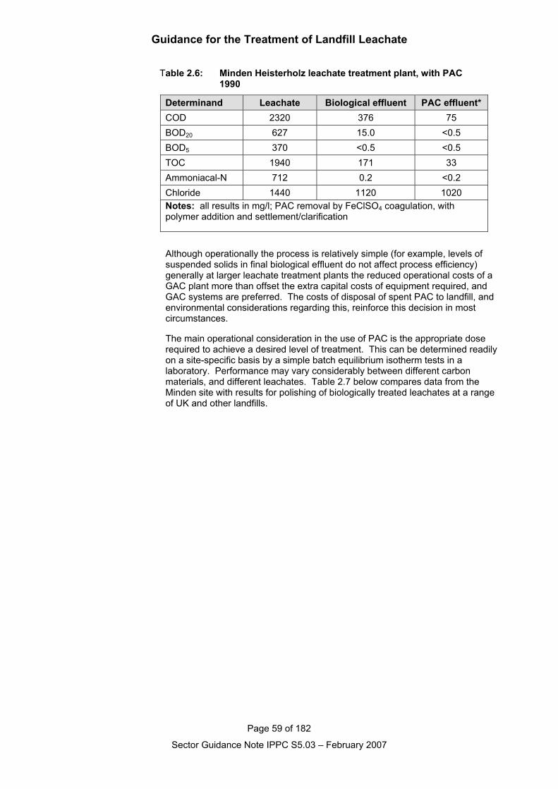
Guidance for the Treatment of Landfill Leachate
Page 59 of 182
Sector Guidance Note IPPC S5.03 – February 2007
Table 2.6: Minden Heisterholz leachate treatment plant, with PAC 1990
Determinand Leachate Biological effluent PAC effluent*COD 2320 376 75BOD20 627 15.0 <0.5BOD5 370 <0.5 <0.5TOC 1940 171 33Ammoniacal-N 712 0.2 <0.2Chloride 1440 1120 1020Notes: all results in mg/l; PAC removal by FeClSO4 coagulation, withpolymer addition and settlement/clarification
Although operationally the process is relatively simple (for example, levels ofsuspended solids in final biological effluent do not affect process efficiency)generally at larger leachate treatment plants the reduced operational costs of aGAC plant more than offset the extra capital costs of equipment required, andGAC systems are preferred. The costs of disposal of spent PAC to landfill, andenvironmental considerations regarding this, reinforce this decision in mostcircumstances.
The main operational consideration in the use of PAC is the appropriate doserequired to achieve a desired level of treatment. This can be determined readilyon a site-specific basis by a simple batch equilibrium isotherm tests in alaboratory. Performance may vary considerably between different carbonmaterials, and different leachates. Table 2.7 below compares data from theMinden site with results for polishing of biologically treated leachates at a rangeof UK and other landfills.
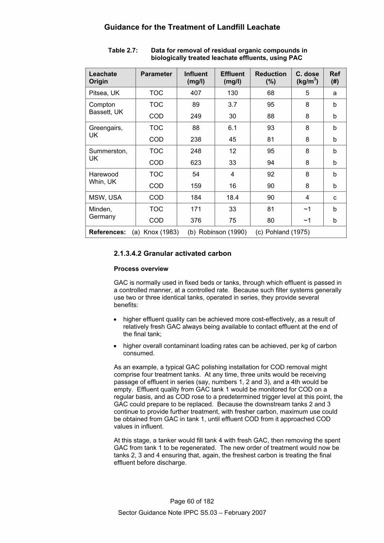
Guidance for the Treatment of Landfill Leachate
Page 60 of 182
Sector Guidance Note IPPC S5.03 – February 2007
Table 2.7: Data for removal of residual organic compounds in biologically treated leachate effluents, using PAC
LeachateOrigin
Parameter Influent(mg/l)
Effluent(mg/l)
Reduction(%)
C. dose(kg/m3)
Ref(#)
Pitsea, UK TOC 407 130 68 5 a
TOC 89 3.7 95 8 bComptonBassett, UK COD 249 30 88 8 b
TOC 88 6.1 93 8 bGreengairs,UK COD 238 45 81 8 b
TOC 248 12 95 8 bSummerston,UK COD 623 33 94 8 b
TOC 54 4 92 8 bHarewoodWhin, UK COD 159 16 90 8 b
MSW, USA COD 184 18.4 90 4 c
TOC 171 33 81 ~1 bMinden,Germany COD 376 75 80 ~1 b
References: (a) Knox (1983) (b) Robinson (1990) (c) Pohland (1975)
2.1.3.4.2 Granular activated carbon
Process overview
GAC is normally used in fixed beds or tanks, through which effluent is passed ina controlled manner, at a controlled rate. Because such filter systems generallyuse two or three identical tanks, operated in series, they provide severalbenefits:
• higher effluent quality can be achieved more cost-effectively, as a result ofrelatively fresh GAC always being available to contact effluent at the end ofthe final tank;
• higher overall contaminant loading rates can be achieved, per kg of carbonconsumed.
As an example, a typical GAC polishing installation for COD removal mightcomprise four treatment tanks. At any time, three units would be receivingpassage of effluent in series (say, numbers 1, 2 and 3), and a 4th would beempty. Effluent quality from GAC tank 1 would be monitored for COD on aregular basis, and as COD rose to a predetermined trigger level at this point, theGAC could prepare to be replaced. Because the downstream tanks 2 and 3continue to provide further treatment, with fresher carbon, maximum use couldbe obtained from GAC in tank 1, until effluent COD from it approached CODvalues in influent.
At this stage, a tanker would fill tank 4 with fresh GAC, then removing the spentGAC from tank 1 to be regenerated. The new order of treatment would now betanks 2, 3 and 4 ensuring that, again, the freshest carbon is treating the finaleffluent before discharge.
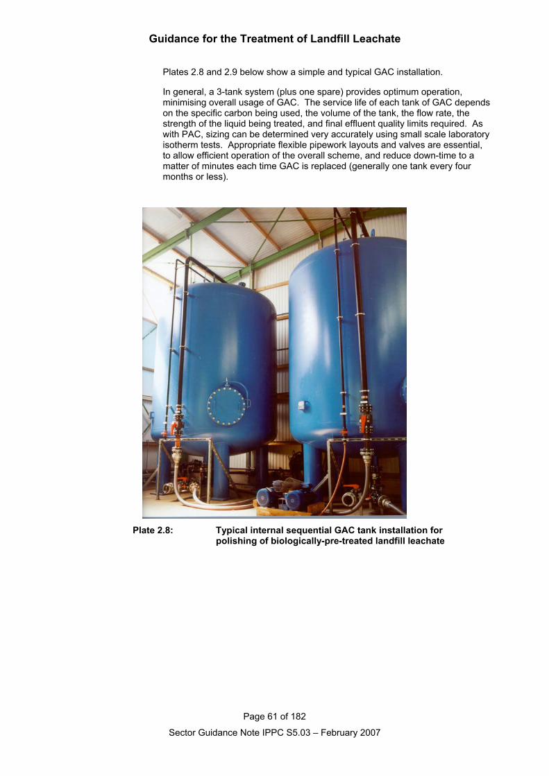
Guidance for the Treatment of Landfill Leachate
Page 61 of 182
Sector Guidance Note IPPC S5.03 – February 2007
Plates 2.8 and 2.9 below show a simple and typical GAC installation.
In general, a 3-tank system (plus one spare) provides optimum operation,minimising overall usage of GAC. The service life of each tank of GAC dependson the specific carbon being used, the volume of the tank, the flow rate, thestrength of the liquid being treated, and final effluent quality limits required. Aswith PAC, sizing can be determined very accurately using small scale laboratoryisotherm tests. Appropriate flexible pipework layouts and valves are essential,to allow efficient operation of the overall scheme, and reduce down-time to amatter of minutes each time GAC is replaced (generally one tank every fourmonths or less).
Plate 2.8: Typical internal sequential GAC tank installation for polishing of biologically-pre-treated landfill leachate
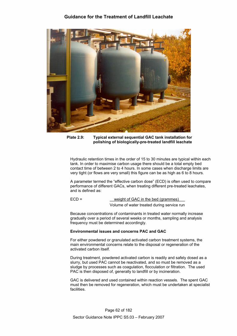
Guidance for the Treatment of Landfill Leachate
Page 62 of 182
Sector Guidance Note IPPC S5.03 – February 2007
Plate 2.9: Typical external sequential GAC tank installation for polishing of biologically-pre-treated landfill leachate
Hydraulic retention times in the order of 15 to 30 minutes are typical within eachtank. In order to maximise carbon usage there should be a total empty bedcontact time of between 2 to 4 hours. In some cases when discharge limits arevery tight (or flows are very small) this figure can be as high as 6 to 8 hours.
A parameter termed the “effective carbon dose” (ECD) is often used to compareperformance of different GACs, when treating different pre-treated leachates,and is defined as:
ECD = weight of GAC in the bed (grammes) Volume of water treated during service run
Because concentrations of contaminants in treated water normally increasegradually over a period of several weeks or months, sampling and analysisfrequency must be determined accordingly.
Environmental issues and concerns PAC and GAC
For either powdered or granulated activated carbon treatment systems, themain environmental concerns relate to the disposal or regeneration of theactivated carbon itself.
During treatment, powdered activated carbon is readily and safely dosed as aslurry, but used PAC cannot be reactivated, and so must be removed as asludge by processes such as coagulation, flocculation or filtration. The usedPAC is then disposed of, generally to landfill or by incineration.
GAC is delivered and used contained within reaction vessels. The spent GACmust then be removed for regeneration, which must be undertaken at specialistfacilities.
Guidance for the Treatment of Landfill Leachate
Page 63 of 182
Sector Guidance Note IPPC S5.03 – February 2007
The presence of persistent organic pollutants that have been adsorbed ontoeither form of activated carbon will limit locations where they can beregenerated or disposed of safely.
2.1.3.5 Ion exchange
Ion exchange removes ions from an aqueous solution by the exchange ofanions or cations between contaminants and the exchange medium. Ionexchange materials typically consist of resins made from synthetic organicmaterials, which contain ionic functional groups to which exchangeable ions areattached. They may also be inorganic or natural polymeric materials.
Ion exchange processes are most widely used in potable water treatment, andhave been successfully applied to nitrate removal, or to water softening (seeHall and Hyde, 1992). For nitrate removal, water is passed through a bed ofsynthetic resin beads, which remove anions including nitrate from the water,exchanging them for equivalent amounts of chloride. When the capacity forexchange is saturated, the bed is taken out of operation and the resinregenerated with sodium chloride brine (~10 percent w/v), which returns theresin to the chloride form. The bed is then rinsed with clean water and returnedto service. Used regenerant contains high concentrations of sodium chloride,as well as nitrate (and sulphate) removed from the bed, and must be disposedof, often to sewer.
For water softening, cationic resin is instead used, which can be regeneratedeither using NaCl, or acid, but the process is essentially similar.
Application of ion exchange processes to the treatment or polishing of landfillleachates has to date been limited by the very high concentrations of anions(e.g. chloride, nitrate-N to 2000+ mg/l) and cations (e.g. sodium, calcium to1000+ mg/l) present in raw or biologically pre-treated leachates. This continuesto restrict any cost-effective applications for leachate treatment.
The complexity and variability in composition of leachate, including thepresence of multiple contaminants makes it unlikely that naturally occurring ionexchange materials will be suitable for treating leachate. The presence ofhydrocarbons may also cause the media to be blinded. Zeolite has been usedfor ammonia removal but regeneration has not proven cost effective andtherefore the technology may be more applicable to sites where the flow ratesand ammonia concentrations are small.
That is not to say that ion exchange processes may not be developed in future,which may find useful applications. If suitable systems can be developed,operated in contact with leachates to provide cost-effective treatment of specificions, and demonstrated in pilot-scale tests, they should be considered seriouslyat that stage.
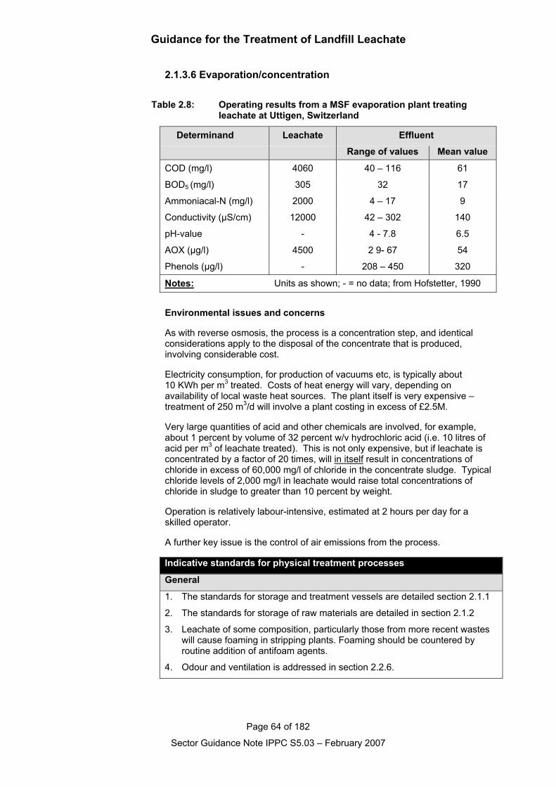
Guidance for the Treatment of Landfill Leachate
Page 64 of 182
Sector Guidance Note IPPC S5.03 – February 2007
2.1.3.6 Evaporation/concentration
Table 2.8: Operating results from a MSF evaporation plant treating leachate at Uttigen, Switzerland
Determinand Leachate Effluent
Range of values Mean value
COD (mg/l) 4060 40 – 116 61
BOD5 (mg/l) 305 32 17
Ammoniacal-N (mg/l) 2000 4 – 17 9
Conductivity (µS/cm) 12000 42 – 302 140
pH-value - 4 - 7.8 6.5
AOX (µg/l) 4500 2 9- 67 54
Phenols (µg/l) - 208 – 450 320
Notes: Units as shown; - = no data; from Hofstetter, 1990
Environmental issues and concerns
As with reverse osmosis, the process is a concentration step, and identicalconsiderations apply to the disposal of the concentrate that is produced,involving considerable cost.
Electricity consumption, for production of vacuums etc, is typically about10 KWh per m3 treated. Costs of heat energy will vary, depending onavailability of local waste heat sources. The plant itself is very expensive –treatment of 250 m3/d will involve a plant costing in excess of £2.5M.
Very large quantities of acid and other chemicals are involved, for example,about 1 percent by volume of 32 percent w/v hydrochloric acid (i.e. 10 litres ofacid per m3 of leachate treated). This is not only expensive, but if leachate isconcentrated by a factor of 20 times, will in itself result in concentrations ofchloride in excess of 60,000 mg/l of chloride in the concentrate sludge. Typicalchloride levels of 2,000 mg/l in leachate would raise total concentrations ofchloride in sludge to greater than 10 percent by weight.
Operation is relatively labour-intensive, estimated at 2 hours per day for askilled operator.
A further key issue is the control of air emissions from the process.
Indicative standards for physical treatment processes
General
1. The standards for storage and treatment vessels are detailed section 2.1.1
2. The standards for storage of raw materials are detailed in section 2.1.2
3. Leachate of some composition, particularly those from more recent wasteswill cause foaming in stripping plants. Foaming should be countered byroutine addition of antifoam agents.
4. Odour and ventilation is addressed in section 2.2.6.
Guidance for the Treatment of Landfill Leachate
Page 65 of 182
Sector Guidance Note IPPC S5.03 – February 2007
5. Fugitive emissions to air are addressed in section 2.2.4
Methane stripping
1. Adequate volumes of air shall be used during the stripping process to keepconcentrations of methane present in the exhaust gas well below explosivelevels.
2. Close control of the air input during the operation of the plant can be used toreduce the precipitation of inorganic scale within the stripping reactors, ordownstream pipework. Provision of additional flow capacity in thedownstream pipework increases the period between pipe cleaningoperations.
Removal of Ammoniacal-N by Air Stripping
1. If raising pH-value is used to increase the process efficiency, high dosagesof alkali (typically in the range 3-8 kg of Ca(OH)2 per m3 treated) will berequired, and effluent may subsequently require acid neutralisation beforedischarge, such dosing should be undertaken using automatic calibrated in-line dosing pumps.
2. Operation at elevated temperatures will reduce alkalinity requirements, usecan be made of landfill gas, or of waste heat from landfill gas powergeneration schemes an option. In the event that the operator proposes touse energy other than waste heat to raise the process temperatureconsideration should be give to alternative uses of this energy to determinewhich represents BAT.
3. Precipitation of inorganic and organic materials may cause scaling andclogging problems if packed towers are used for the stripping operation, andmay result in a requirement for removal and disposal of sludges.Procedures must be in place that ensures that the identification of anyscaling or clogging within the pack tower and for subsequent managementand disposal of sludge arising.
4. Where relatively high effluent concentrations of ammoniacal-N are accepted(e.g. 100-200 mg/l), greatly reduced aeration rates can be achieved.Leachate will require secondary biological treatment if effluent discharge towatercourses is an option, the removal of ammoniacal-N to very low levelsduring stripping can result in nitrogen deficiency in secondary stages oftreatment
5. Release of ammonia gas in exhaust air may be controlled by thermaldestruction in a landfill gas flare. When considering the utilisation of landfillgas flares for thermal destruction the impact on the emissions from the flarehave to be considered.
Reverse osmosis
1. The return of retenate to the landfill shall only take place if:
Any predicted change in leachate concentration has been assessed; it must be shown that the landfill is adequately engineered so that the
concentrate does not cause pollution (particular attention should begiven to the impact on groundwater, an appropriate source term shouldbe modelled in the landfill site’s hydrogeological risk assessment);
it must be shown that the leachate treatment system can adequatelytreat any predicted change in leachate quality resulting from the returnof the concentrate;
chemicals essential to the effective operation of the plant should beselected so as not to compromise the disposal of the concentrate; and
the leachate originated from the landfill site (i.e. no imported leachate).
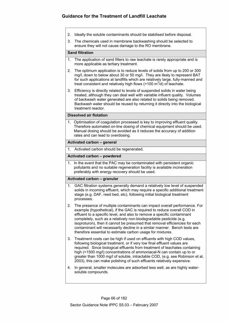
Guidance for the Treatment of Landfill Leachate
Page 66 of 182
Sector Guidance Note IPPC S5.03 – February 2007
2. Ideally the soluble contaminants should be stabilised before disposal.
3. The chemicals used in membrane backwashing should be selected toensure they will not cause damage to the RO membrane.
Sand filtration
1. The application of sand filters to raw leachate is rarely appropriate and ismore applicable as tertiary treatment.
2. The optimum application is to reduce levels of solids from up to 200 or 300mg/l, down to below about 30 or 50 mg/l. They are likely to represent BATfor such applications at landfills which are relatively large, fully-manned andtreat consistent and relatively high flows (>100 m3/d) of leachate.
3. Efficiency is directly related to levels of suspended solids in water beingtreated, although they can deal well with variable influent quality. Volumesof backwash water generated are also related to solids being removed.Backwash water should be reused by returning it directly into the biologicaltreatment reactor.
Dissolved air flotation
1. Optimisation of coagulation processed is key to improving effluent quality.Therefore automated on-line dosing of chemical equipment should be used.Manual dosing should be avoided as it reduces the accuracy of additionrates and can lead to overdosing.
Activated carbon – general
1. Activated carbon should be regenerated.
Activated carbon – powdered
1. In the event that the PAC may be contaminated with persistent organicpollutants and no suitable regeneration facility is available incinerationpreferably with energy recovery should be used.
Activated carbon – granular
1. GAC filtration systems generally demand a relatively low level of suspendedsolids in incoming effluent, which may require a specific additional treatmentstage (e.g. DAF, reed bed, etc), following initial biological treatmentprocesses.
2. The presence of multiple contaminants can impact overall performance. Forexample (hypothetical), if the GAC is required to reduce overall COD ineffluent to a specific level, and also to remove a specific contaminantcompletely, such as a relatively non-biodegradable pesticide (e.g.isoproturon), then it cannot be presumed that removal efficiencies for eachcontaminant will necessarily decline in a similar manner. Bench tests aretherefore essential to estimate carbon usage for mixtures.
3. Treatment costs can be high if used on effluents with high COD values,following biological treatment, or if very low final effluent values arerequired. Since biological effluents from treatment of leachates containinghigh (>1500 mg/l) concentrations of ammoniacal-N can contain up to orgreater than 1000 mg/l of soluble, intractable COD, (e.g. see Robinson et al,2003), this can make polishing of such effluents relatively expensive.
4. In general, smaller molecules are adsorbed less well, as are highly water-soluble compounds.
Guidance for the Treatment of Landfill Leachate
Page 67 of 182
Sector Guidance Note IPPC S5.03 – February 2007
5. Spent carbon, possibly containing some hazardous compounds which, havebeen concentrated within it (e.g. chlorinated compounds and pesticides), willrequire regeneration (and safe destruction of these compounds) at one ofonly 2 or 3 locations in the UK. Proximity of the treatment plant to such alocation may impact on costs for carbon, and overall unit costs of treatment.
Guidance for the Treatment of Landfill Leachate
Page 68 of 182
Sector Guidance Note IPPC S5.03 – February 2007
2.1.4 Chemical treatment processes
2.1.4.1 Chemical oxidation processes
Chemical oxidation processes are potential treatment options for the removal ofspecific organic and inorganic pollutants from landfill leachates, but are unlikely toprovide full treatment of the wide range of contaminants present in typical samples.Oxidation involves the loss of one or more electrons from the element beingoxidised – the electron acceptor being another element, including an oxygenmolecule, or a chemical species containing oxygen, such as hydrogen peroxide,ozone, or some other electron acceptor.
In practice, the application of such processes will be restricted by cost, by the rateof reaction possible (oxidation rates for some organic compounds may be tooslow), and by the availability of alternative treatment processes for specificcontaminants.
In a complex wastewater such as leachate, the amount of chemical oxidantrequired in practice, is generally greater than the theoretical mass calculated fromfirst principles. This results from a number of reasons, including incompleteoxidant consumption, and lack of specificity of the desired process – oxidant alsobeing consumed by other chemical reactions. Oxidation reactions are often pH-dependent, and control of pH-values may be an important consideration.
For treatment of landfill leachates, a limited range of oxidants have foundsuccessful application to date, primarily ozone or hydrogen peroxide. Use ofothers has been limited by concerns about formation of toxic reaction by-products– for example, chlorine and chlorine compounds giving rise to trihalomethanes, orother halogenated compounds.
Nevertheless, in specific situations, chemical oxidation processes can provideparticular benefits – for example, at elevated pH-values, cyanide can be oxidisedto carbon dioxide and nitrogen using sodium hypochlorite (e.g. see Patterson,1985). It is likely, therefore, that chemical oxidation processes will find onlyoccasional application in leachate treatment, and then to deal with individual andsite-specific circumstances. Ozonation and use of hydrogen peroxide will probablyaccount for most applications.
For all reagent-based chemical oxidation processes, the storage and handling ofpotentially hazardous chemicals must be addressed and considered, andappropriate standards of design and care applied. If extreme conditions arerequired within a treatment reactor, then high standards of control and containmentbecome even more important safety considerations.
Because of their nature, advanced chemical oxidation processes continue to bedeveloped experimentally. Examples include wet air oxidation, andelectrochemical oxidation systems. At the time of drafting, these have not beensuccessfully applied to leachate treatment, but over coming decades it is possiblethat novel processes may be developed and need to be considered.
Guidance for the Treatment of Landfill Leachate
Page 69 of 182
Sector Guidance Note IPPC S5.03 – February 2007
2.1.4.1.1. Ozonation
General information
Ozonation is well established as a treatment technology for drinking waters, or inswimming pools, for which it is used as a disinfectant, to degrade substances ofconcern, and to enhance the performance of other treatment processes. Althoughnot so widely employed for the treatment of sewage or industrial wastewaters,ozonation has much to offer in specific circumstances.
Ozone is the strongest practical oxidant available for waste water treatment, and isused for:
Oxidation of organic materials, especially recalcitrant organic compounds,to enhance their removal by subsequent treatment – especially in biologicalprocesses;
Disinfection;
Taste, odour, and colour removal;
As a pre-oxidant stage to enhance removal of turbidity and algae withinsubsequent treatment processes; and
Precipitation of iron and manganese.
Capital costs of ozone treatment are relatively high (typically £250K to £350K todose 150 mg/l into 200 m3 of effluent per day), due to the high cost of equipmentfor ozone generation. Electricity comprises the majority of operational costs, whichcan also be high, especially for stronger leachates.
Ozonation should be seen as an expensive polishing option, appropriate only inspecific circumstances for leachate treatment, such as complete destruction of lessbiologically-degradable pesticides in final effluents. Nevertheless, case studies inthe UK and overseas have demonstrated that such systems can operate reliablyon landfill sites.
Process overview
Ozone itself (O3) is an allotrope of oxygen, and is a gas at normal temperaturesand pressures. It is relatively unstable, having a half-life of less than 30 minutes indistilled water at 30°C (Reynolds, 1982). Because of this instability, ozone musttherefore be generated at the point of use, by passing air or pure oxygen betweenoppositely charged plates. The gases having been pre-dried to a dew point lowerthan about -40°C. Pure oxygen feed is generally only more cost-effective than airfor ozonation systems that are required to generate more than 1 tonne of ozoneper day. For smaller systems (typical leachate applications will require less than50 kg of ozone per day) then air is generally used.
Once produced, air containing enhanced concentrations of ozone gas is bubbledthrough the water to be treated in a column, using a bubble diffuser system.Generally, a batch system of treatment is preferred, with a contact time of between15 minutes and an hour.
Ozone transfer occurs as fine bubbles containing ozone and air (or oxygen) thatrise slowly inside the column, contacting the contaminated water phase. Correctozone dosage to achieve required oxidation of specific compounds is generallydetermined using small-scale treatability studies. Pesticides, aromatics, alkanesand alkenes are examples of compounds readily and successfully treatable byozonation.
Guidance for the Treatment of Landfill Leachate
Page 70 of 182
Sector Guidance Note IPPC S5.03 – February 2007
Ozone treatment is generally only appropriate as a polishing step in the treatmentof landfill leachates, following extensive biological pre-treatment to removedegradable organic compounds that might otherwise result in excessiveconsumption of ozone. Removal of suspended solids from water being treated isalso essential for efficient treatment. In addition, ozonation is best applied to wellnitrified or low ammonia containing effluents, since to some extent ammonia alsocompetes for ozone with the organic compounds being targeted.
Environmental issues and concerns
Unlike chlorine, the use of ozone for effluent polishing does not result in excessiveformation of trihalomethanes. However, as well as directly degrading someorganic compounds, ozone can increase the degradability of organic compounds,resulting in increased levels of BOD in effluents. These can then readily bedegraded efficiently, using passive processes such as reed bed polishing.Particularly during treatment of landfill leachates, ozonation can result ingeneration of very reactive brominated intermediate compounds (e.g. bromal, =tribromoacetaldehyde). Experience has demonstrated that although suchcompounds exhibit significant toxicity, they are readily and completely degradedwithin an appropriately designed reed bed polishing system.
There is only one example of a full-scale leachate treatment plant in the UK whereozonation has been applied as a polishing stage for leachate treatment. In thatinstance, ozonation was applied to meet extremely stringent effluent toxicitycriteria, before discharge into a very sensitive receiving watercourse. The planthas operated successfully since 1994, particularly for the complete removal of anumber of pesticides, such as mecoprop and isoproturon, in biologically pre-treated leachate. Experience has been that ozonation generally only providesbetween 10-15 percent removal of residual hard COD, and that if COD levels infinal effluent are a major issue, then alternative polishing processes, such asactivated carbon, may be more appropriate.
Where removal of adsorbable organic halogens (AOX) is an issue, ozonation hasbeen shown to be capable of reducing values of AOX from up to 3 mg/l, to below0.5 mg/l (e.g. see Kaulbach, 1993). Costs of such treatment, where required, mustbe compared with those of alternative processes, such as activated carbonadsorption.
Although variants of ozonation, involving combined treatment with hydrogenperoxide (H2O2), and/or Ultra Violet irradiation, are capable of providing increasedoxidation potential by the enhanced generation of hydroxyl radicals, suchprocesses have rarely been applied to treatment of landfill leachates.
2.1.4.1.2 Hydrogen Peroxide
General information
Hydrogen peroxide (H2O2) is a strong oxidising agent generally supplied as a 35%w/v solution. Use of hydrogen peroxide has found many applications to oxidisecontaminants in industrial wastewaters. In the presence of a catalyst, such as iron,hydrogen peroxide (H2O2) generates hydroxyl radicals (*OH), which can react withreduced compounds and specific organics.
For leachate treatment, peroxide treatment systems have ranged from very simpledrip feed dosing into open leachate lagoons, through pumped dosing into the inletof large recirculation pumps, to fully engineered dosing systems into mixedreactors. Dosing of hydrogen peroxide has sometimes also been incorporatedwithin simple methane stripping systems for leachate (see earlier), in order to meetdischarge consents for entry of leachate into the public sewer. Hydrogen peroxideand potassium permanganate have also been used successfully to treat odorous
Guidance for the Treatment of Landfill Leachate
Page 71 of 182
Sector Guidance Note IPPC S5.03 – February 2007
leachates for short periods by turning the leachates aerobic and reducing thepotential to cause odour.
Process overview
In leachate treatment, hydrogen peroxide oxidation has been applied principally tooxidise sulphide, although experience from other industries has shown that manyother contaminants which might be found in leachates can also potentially betreated (eg phenols, sulphite, cyanide, formaldehyde, etc).
For oxidation of sulphide, reactions depend on pH-value as below:
(a) acidic or neutral pH
H2O2 + H2S → 2H2O + SReaction time 15-45 minutes (much quicker if catalysed by Fe2+)
(b) Basic pH
4H2O2 + S2- → SO42- + 4H2O
Reaction time 15 minutes
Sulphide levels have been successfully managed at between 10 – 20 UK landfillsites, either to control odours, or to comply with limits for discharges of leachatesinto sewers. Under the optimum pH-value conditions of neutral or slightly acid, thereaction of peroxide and sulphide is relatively specific, and chemical requirementsof about 25 percent greater than those predicted in equation (a) have generallyproved to be appropriate, with a reaction time of about 30 minutes. Laboratorytrials may be valuable in optimising chemical dosing rates.
Environmental issues and concerns
Principle concerns over Hydrogen Peroxide relate to storage and handling issuesand ensuring that in the event of a spillage adequate controlls are in place (spillkits, bunding and training) to protect sensitive environmental receptors.
Hydrogen Peroxide is a strong oxidising agent and as such must not be allowed tocome into contact with incompatable materials.
2.1.4.2 Precipitation/coagulation/flocculation
2.1.4.2.1 Chemical precipitation of metals
General information
It has been widely demonstrated that, with the exception of levels of zinc inacetogenic leachate samples, concentrations of heavy metals in leachates fromlandfills containing primarily household wastes are relatively low. Typical valuesare generally lower than those measured in samples of domestic sewage, and farlower than levels of metals being treated at sewage treatment works, where inputsof industrial effluent have also been received. Median values for key metals inleachates from modern large landfills, with high waste input rates (including co-disposal sites and sites receiving industrial and commercial wastes) are reportedbelow, and are compared with values for non-industrial crude sewage (in mg/l,after Robinson, 1995).
Guidance for the Treatment of Landfill Leachate
Page 72 of 182
Sector Guidance Note IPPC S5.03 – February 2007
Table 2.9 Median values for key metals in leachate
Metal Acetogenicleachate
Methanogenicleachate
Domestic sewage(range of values)
Chromium 0.12 0.07 0.01 - 0.17
Nickel 0.23 0.14 0.01 - 0.19
copper 0.07 0.07 0.06 - 0.50
zinc 6.85 0.78 0.10 - 1.65
cadmium 0.01 <0.01 0.001 - 0.03
lead 0.30 0.13 0.03 - 0.395
Additionally, significant removal of some of these metals in leachate (e.g. zinc,chromium, copper) has been reported during aerobic biological treatment (seeRobinson and Knox, 2001).
On this basis, chemical treatment to reduce concentrations of metals is unlikely tobe widely required, in particular at landfills which, receive significant inputs ofhousehold wastes, or where leachates are treated biologically before discharge.Precipitation and other reactions within an anaerobic landfill will generally reducethe mobility of heavy metals significantly.
Nevertheless, if specific circumstances require such metal removal, chemicalprecipitation processes are widely employed for this purpose, for effluents in awide variety of industries, and could readily be adopted.
Although specific treatment processes for removal of heavy metals from landfillleachates will only occasionally be necessary, and have rarely been provided atUK landfill sites, on occasions when specific features of landfills require suchtreatment, there is a wealth of experience and data to allow appropriate systems tobe designed (e.g. see Eckenfelder, 1989).
Difficulties may arise from the relatively low concentrations of heavy metalspresent in leachates, reducing the cost-effectiveness of the process, and alsowhere there is a need to remove mixtures of metals, and these have differentoptimum pH-values for precipitation.
Process overview
Precipitation is widely employed for the removal of concentrations of heavy metalsfrom industrial wastewaters, and although many chemicals have been used (e.g.hydrated lime, quicklime, magnesium hydroxide, sodium hydroxide), hydrated lime,Ca (OH)2, has been most widely used, and is generally the cheapest. Heavymetals are usually precipitated as the hydroxide through the addition of alkali, to apH-value at which solubility of the metal of interest is minimised. Several metalsare amphoteric, and exhibit a point of minimum solubility, below or above whichsolubility will increase and removal will reduce. Examples are chromium (pH value7.5), and zinc (pH value 10.2).
Although many leachates have been shown to contain organic complexing agents,which have potential to interfere with metal removal (especially at relatively lowconcentrations in leachate), excellent removal of metals has nevertheless beenreported by many authors (e.g. Knox, 1983; Bjorkman and Mavinic, 1977; Chianand DeWalle, 1977).
Guidance for the Treatment of Landfill Leachate
Page 73 of 182
Sector Guidance Note IPPC S5.03 – February 2007
All precipitation processes are very strongly influenced by the pollution matrix ofspecific leachates, and as a consequence, laboratory and pilot-scale trials areessential if the process is to be optimised, and efficient treatment systems are tobe developed, and operated to achieve effluent limits reliable and cost-effectively.
The wastewater treatment industry has extensive experience which enables it toprovide appropriate precipitation processes, which take advantage of a range ofchemical phenomena including co-precipitation and adsorptive co-precipitation, sothat residual metal solubility levels far below theoretical solubility limits for simplemetal salts can commonly be achieved. Similarly, appropriate subsequenttreatment stages of flocculation, sedimentation and clarification; can be optimisedbased on experience. Volumes and handling characteristics of precipitatedsludges are frequently at least as important as economic factors, in final selectionor optimisation of precipitation processes.
Environmental issues and concerns
Principal environmental issues relate to the correct storage of chemicals, correctdosing to prevent excessive use of reagents and sludge disposal. Sludge may bedewatered to facilitate handling transportation and disposal. Typically, disposal willby landfill depending on Landfill Regulations limitations.
2.1.4.2.2 Coagulation and flocculation
General information
Chemical coagulation and flocculation are used for the removal of waste materialspresent in suspended or colloidal form. Colloids represent particles typically withina size range from 1.0nm to 0.1nm (10-7 to 10-8 cm). These particles do not settleout on standing, and are not readily removed by conventional physical treatmentprocesses.
Coagulants, usually salts of iron or aluminium, are added at controlled pH-valuesto form solid precipitates termed floc, which contain the colloidal particles, and canthen be separated out using conventional solid, liquid separation processes. Theprocess of flocculation encourages floc growth by gentle mixing, to suite thesubsequent separation process being used.
Process overview
In leachate treatment at UK landfills, full-scale coagulation/flocculation systemshave rarely, if ever, been applied to the raw leachates, and only occasionally tobiologically pre-treated effluents.
Nevertheless, in other countries such as Germany, coagulation and flocculationprocesses are more widely applied to both raw and treated leachates, andextensive experience is available. Common applications have included:
• Removal of turbidity and colour from biological treatment effluents;
• Reduction in COD values associated with colloidal materials;
• Removal of powdered activated carbon (PAC) in effluent polishing (seeseparate section);
• Reduction in suspended solids concentrations, to protect subsequenttreatment stages – e.g. in activated carbon columns.
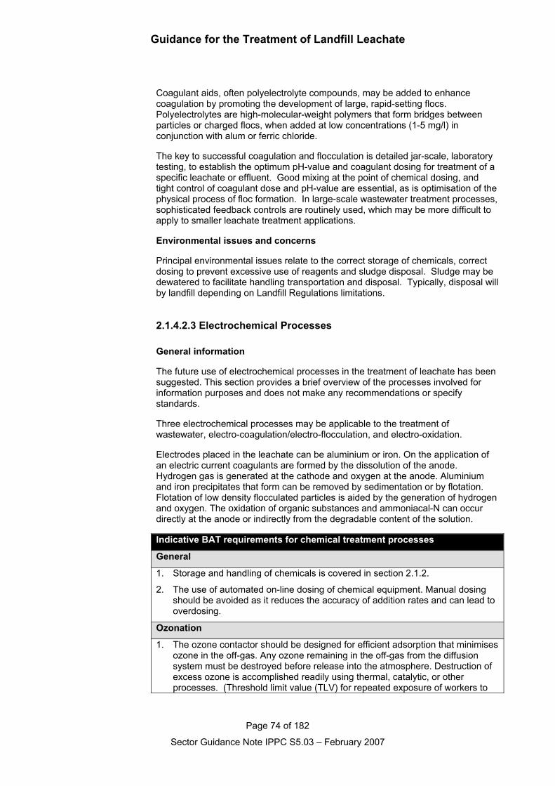
Guidance for the Treatment of Landfill Leachate
Page 74 of 182
Sector Guidance Note IPPC S5.03 – February 2007
Coagulant aids, often polyelectrolyte compounds, may be added to enhancecoagulation by promoting the development of large, rapid-setting flocs.Polyelectrolytes are high-molecular-weight polymers that form bridges betweenparticles or charged flocs, when added at low concentrations (1-5 mg/l) inconjunction with alum or ferric chloride.
The key to successful coagulation and flocculation is detailed jar-scale, laboratorytesting, to establish the optimum pH-value and coagulant dosing for treatment of aspecific leachate or effluent. Good mixing at the point of chemical dosing, andtight control of coagulant dose and pH-value are essential, as is optimisation of thephysical process of floc formation. In large-scale wastewater treatment processes,sophisticated feedback controls are routinely used, which may be more difficult toapply to smaller leachate treatment applications.
Environmental issues and concerns
Principal environmental issues relate to the correct storage of chemicals, correctdosing to prevent excessive use of reagents and sludge disposal. Sludge may bedewatered to facilitate handling transportation and disposal. Typically, disposal willby landfill depending on Landfill Regulations limitations.
2.1.4.2.3 Electrochemical Processes
General information
The future use of electrochemical processes in the treatment of leachate has beensuggested. This section provides a brief overview of the processes involved forinformation purposes and does not make any recommendations or specifystandards.
Three electrochemical processes may be applicable to the treatment ofwastewater, electro-coagulation/electro-flocculation, and electro-oxidation.
Electrodes placed in the leachate can be aluminium or iron. On the application ofan electric current coagulants are formed by the dissolution of the anode.Hydrogen gas is generated at the cathode and oxygen at the anode. Aluminiumand iron precipitates that form can be removed by sedimentation or by flotation.Flotation of low density flocculated particles is aided by the generation of hydrogenand oxygen. The oxidation of organic substances and ammoniacal-N can occurdirectly at the anode or indirectly from the degradable content of the solution.
Indicative BAT requirements for chemical treatment processes
General
1. Storage and handling of chemicals is covered in section 2.1.2.
2. The use of automated on-line dosing of chemical equipment. Manual dosingshould be avoided as it reduces the accuracy of addition rates and can lead tooverdosing.
Ozonation
1. The ozone contactor should be designed for efficient adsorption that minimisesozone in the off-gas. Any ozone remaining in the off-gas from the diffusionsystem must be destroyed before release into the atmosphere. Destruction ofexcess ozone is accomplished readily using thermal, catalytic, or otherprocesses. (Threshold limit value (TLV) for repeated exposure of workers to
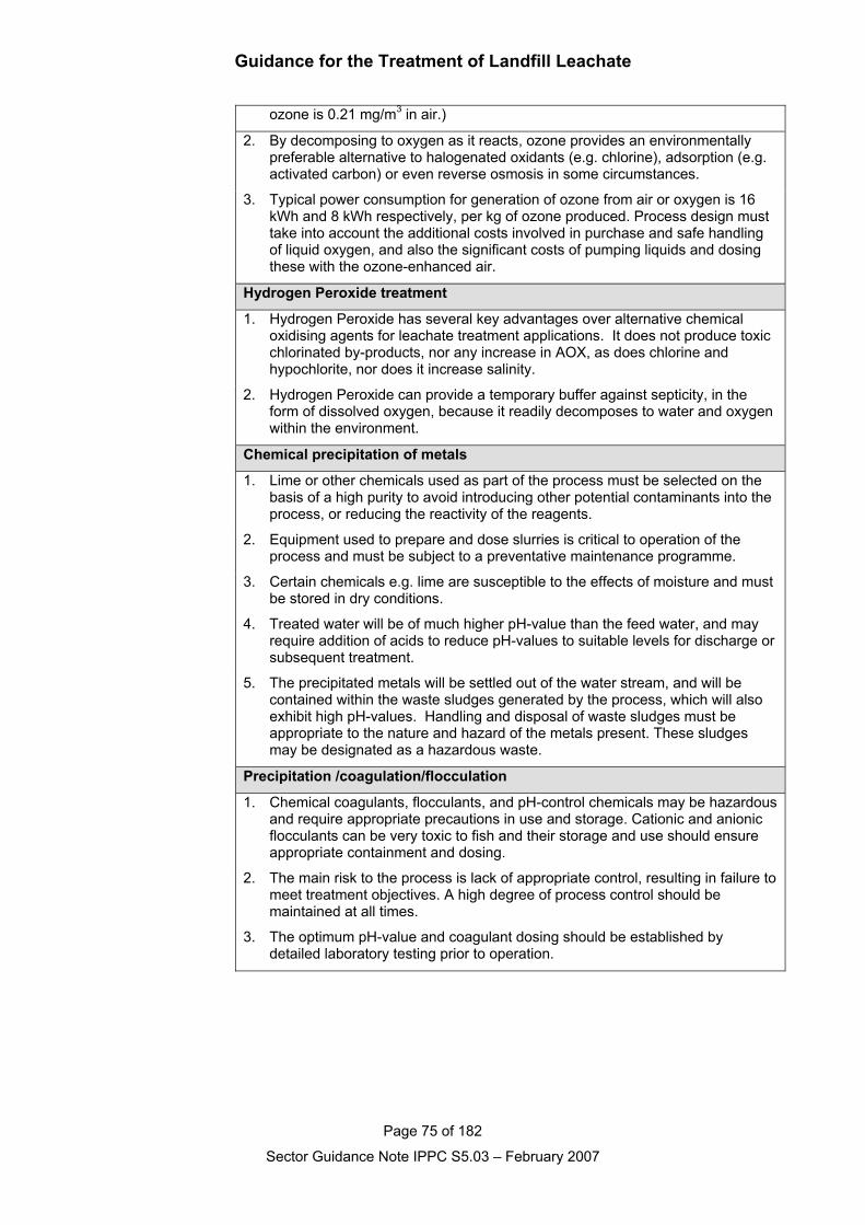
Guidance for the Treatment of Landfill Leachate
Page 75 of 182
Sector Guidance Note IPPC S5.03 – February 2007
ozone is 0.21 mg/m3 in air.)
2. By decomposing to oxygen as it reacts, ozone provides an environmentallypreferable alternative to halogenated oxidants (e.g. chlorine), adsorption (e.g.activated carbon) or even reverse osmosis in some circumstances.
3. Typical power consumption for generation of ozone from air or oxygen is 16kWh and 8 kWh respectively, per kg of ozone produced. Process design musttake into account the additional costs involved in purchase and safe handlingof liquid oxygen, and also the significant costs of pumping liquids and dosingthese with the ozone-enhanced air.
Hydrogen Peroxide treatment
1. Hydrogen Peroxide has several key advantages over alternative chemicaloxidising agents for leachate treatment applications. It does not produce toxicchlorinated by-products, nor any increase in AOX, as does chlorine andhypochlorite, nor does it increase salinity.
2. Hydrogen Peroxide can provide a temporary buffer against septicity, in theform of dissolved oxygen, because it readily decomposes to water and oxygenwithin the environment.
Chemical precipitation of metals
1. Lime or other chemicals used as part of the process must be selected on thebasis of a high purity to avoid introducing other potential contaminants into theprocess, or reducing the reactivity of the reagents.
2. Equipment used to prepare and dose slurries is critical to operation of theprocess and must be subject to a preventative maintenance programme.
3. Certain chemicals e.g. lime are susceptible to the effects of moisture and mustbe stored in dry conditions.
4. Treated water will be of much higher pH-value than the feed water, and mayrequire addition of acids to reduce pH-values to suitable levels for discharge orsubsequent treatment.
5. The precipitated metals will be settled out of the water stream, and will becontained within the waste sludges generated by the process, which will alsoexhibit high pH-values. Handling and disposal of waste sludges must beappropriate to the nature and hazard of the metals present. These sludgesmay be designated as a hazardous waste.
Precipitation /coagulation/flocculation
1. Chemical coagulants, flocculants, and pH-control chemicals may be hazardousand require appropriate precautions in use and storage. Cationic and anionicflocculants can be very toxic to fish and their storage and use should ensureappropriate containment and dosing.
2. The main risk to the process is lack of appropriate control, resulting in failure tomeet treatment objectives. A high degree of process control should bemaintained at all times.
3. The optimum pH-value and coagulant dosing should be established bydetailed laboratory testing prior to operation.