the bantan landfill – landfill opera- tion, and leachate … bantan landfill – landfill...
TRANSCRIPT
BANTAN
REPORT BANTAN_REV2.DOCX 1 - 15 Speicherdatum: 2015-08-26
The Bantan landfill – Landfill opera-tion, and leachate treatment
Integrated Resource Management in Asian Cities the Urban NEXUS
(Water / Energy / Food Security / Land Use)
UU1756
Edited by: Reported to: Dipl.-Ing.(FH) Hubert Wienands Dr.-Ing. Bernd Fitzke WEHRLE Umwelt GmbH Bismarckstr. 1 – 11 79312 Emmendingen Germany
GIZ Project Integrated Resource Management in Asian Cities: the Urban Nexus United Nations, Rajadamnern Nok Avenue UN ESCAP Building, 5th Floor, Environment and Development Division Bangkok 10200, Thailand
BANTAN LANDFILL SITE VISIT REPORT
REPORT BANTAN_REV2.DOCX 2 - 15 Speicherdatum: 2015-08-26
CONTENTS
1. ..... Introduction and Basics ....................................................................................................... 3
2. ..... Landfill site asessment ........................................................................................................ 3
2.1. Landfill data ....................................................................................................................... 3 2.1.1. Catchment area ............................................................................................................................................ 3 2.1.2. Site Location ................................................................................................................................................. 4 2.1.3. Site history .................................................................................................................................................... 4 2.2. Waste Composition ............................................................................................................ 5 2.3. Waste management and landfill operation ........................................................................ 5 2.4. Landfill Health and Safety .................................................................................................. 6 2.5. Landfill fires ....................................................................................................................... 6 2.6. Site construction ................................................................................................................ 6 2.6.1. General observations .................................................................................................................................... 6 2.6.2. Environmental Data....................................................................................................................................... 8 2.6.3. Waste Depth ................................................................................................................................................. 9 2.6.4. Waste Placement .......................................................................................................................................... 9 2.6.5. Sludge Placement ......................................................................................................................................... 9 2.6.6. Base Lining ................................................................................................................................................. 10 2.6.7. Capping Layer ............................................................................................................................................. 10 2.6.8. Surface Water Management ....................................................................................................................... 10 2.7. GAS and LEACHATE ...................................................................................................... 11 2.7.1. Gas ............................................................................................................................................................. 11 2.7.2. Leachate ..................................................................................................................................................... 12
BANTAN LANDFILL SITE VISIT REPORT
REPORT BANTAN_REV2.DOCX 3 - 15 Speicherdatum: 2015-08-26
1. INTRODUCTION AND BASICS
Urban nexus The urban nexus approach aims at integrated planning and management processes which can contribute substantially to the sustainability of cities and their regions. The Economic and Social Comission for Asia and the Pacific (ESCAP) and the Deutsche Gesellschaft für Internationale Zusammenarbeit (GIZ) GmbH are implementing the project “Integrated resource management in Asian Cities: the urban nexus”, financed by the German Federal Ministry for Economic Cooperation and Development (BMZ). The project supports ten cities in six countries, by providing technical advice to municipal administrations for the design, planning and, where possible, implementation of practical nexus initiatives. Experiences gained at the local level will feed into regional dialogue, in support of scaling-up the urban nexus approach.
2. LANDFILL SITE ASESSMENT
2.1. LANDFILL DATA
A site visit was performed on 08 June 2015. Information on the waste inputs, engineering details, and environmental conditions of the site are raised during this visit. Additional site Information by the municipality or other instances were not provided. A questionnaire was not filled. Data collected from other parties during the visit has been verified or information adjusted based on the results of site specific observations made during the visit. The following paragraphs highlight the data obtained and analyzed for Bantan Landfill.
2.1.1. CATCHMENT AREA
Chiang Mai Province is about 685 km from Bangkok in the Mae Ping River basin and is on average at 300 m elevation. Surrounded by the mountain ranges of the Thai highlands, it covers an area of approximately 20,107 km2. The mountains of the Daen Lao Range at the north end of the province, the Thanon Thong Chai Range stretching in a north-south direction, and the Khun Tan Range in the east of the province are covered by rain forest. The capital of Chiang Mai Province, Chiang Mai, is the largest and most culturally significant city in Northern Thailand. It is 700 km north of Bangkok and is situated amongst the highest mountains in the country. The city sits astride the Mae Ping River, a major tributary of the Chao Phraya River. While officially the city (thesaban nakhon) of Chiang Mai only covers most parts of the Mueang Chiang Mai district with a population of 160,000, the city's sprawl extends into several neighboring districts. The Chiang Mai Metropolitan Area has a population of nearly one million people, more than half the total of Chiang Mai Province (source: Wikipedia.com).
BANTAN LANDFILL SITE VISIT REPORT
REPORT BANTAN_REV2.DOCX 4 - 15 Speicherdatum: 2015-08-26
2.1.2. SITE LOCATION
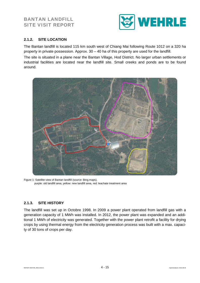
The Bantan landfill is located 115 km south west of Chiang Mai following Route 1012 on a 320 ha property in private possession. Approx. 30 – 40 ha of this property are used for the landfill. The site is situated in a plane near the Bantan Village, Hod District. No larger urban settlements or industrial facilities are located near the landfill site. Small creeks and ponds are to be found around.
Figure 1: Satellite-view of Bantan landfill (source: Bing.maps), purple: old landfill area, yellow: new landfill area, red: leachate treatment area
2.1.3. SITE HISTORY
The landfill was set up in Octobre 1998. In 2009 a power plant operated from landfill gas with a generation capacity of 1 MWh was installed. In 2012, the power plant was expanded and an addi-tional 1 MWh of electricity was generated. Together with the power plant retrofit a facility for drying crops by using thermal energy from the electricity generation process was built with a max. capaci-ty of 30 tons of crops per day.
BANTAN LANDFILL SITE VISIT REPORT
REPORT BANTAN_REV2.DOCX 5 - 15 Speicherdatum: 2015-08-26
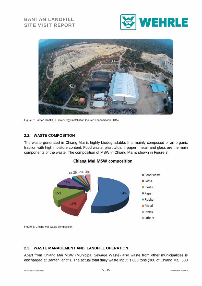
Figure 2: Bantan landfill LFG to energy installation (source Thanomboon 2015)
2.2. WASTE COMPOSITION
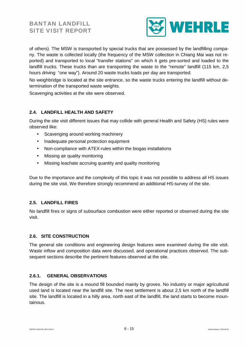
The waste generated in Chiang Mai is highly biodegradable. It is mainly composed of an organic fraction with high moisture content. Food waste, plastic/foam, paper, metal, and glass are the main components of the waste. The composition of MSW in Chiang Mai is shown in Figure 3.
Figure 3: Chiang Mai waste composition
2.3. WASTE MANAGEMENT AND LANDFILL OPERATION
Apart from Chiang Mai MSW (Municipal Sewage Waste) also waste from other municipalities is discharged at Bantan landfill. The actual total daily waste input is 600 tons (300 of Chiang Mai, 300
BANTAN LANDFILL SITE VISIT REPORT
REPORT BANTAN_REV2.DOCX 6 - 15 Speicherdatum: 2015-08-26
of others). The MSW is transported by special trucks that are possessed by the landfilling compa-ny. The waste is collected locally (the frequency of the MSW collection in Chiang Mai was not re-ported) and transported to local “transfer stations” on which it gets pre-sorted and loaded to the landfill trucks. These trucks than are transporting the waste to the “remote” landfill (115 km, 2,5 hours driving “one way”). Around 20 waste trucks loads per day are transported. No weighbridge is located at the site entrance, so the waste trucks entering the landfill without de-termination of the transported waste weights. Scavenging activities at the site were observed.
2.4. LANDFILL HEALTH AND SAFETY
During the site visit different issues that may collide with general Health and Safety (HS) rules were observed like: Scavenging around working machinery Inadequate personal protection equipment Non-compliance with ATEX-rules within the biogas installations Missing air quality monitoring Missing leachate accruing quantity and quality monitoring
Due to the importance and the complexity of this topic it was not possible to address all HS issues during the site visit. We therefore strongly recommend an additional HS-survey of the site.
2.5. LANDFILL FIRES
No landfill fires or signs of subsurface combustion were either reported or observed during the site visit.
2.6. SITE CONSTRUCTION
The general site conditions and engineering design features were examined during the site visit. Waste inflow and composition data were discussed, and operational practices observed. The sub-sequent sections describe the pertinent features observed at the site.
2.6.1. GENERAL OBSERVATIONS
The design of the site is a mound fill bounded mainly by groves. No industry or major agricultural used land is located near the landfill site. The next settlement is about 2,5 km north of the landfill site. The landfill is located in a hilly area, north east of the landfill, the land starts to become moun-tainous.
BANTAN LANDFILL SITE VISIT REPORT
REPORT BANTAN_REV2.DOCX 7 - 15 Speicherdatum: 2015-08-26
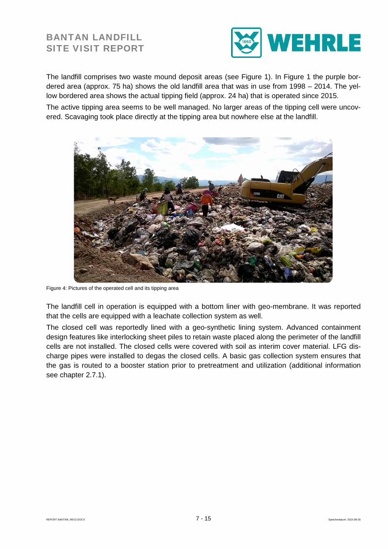
The landfill comprises two waste mound deposit areas (see Figure 1). In Figure 1 the purple bor-dered area (approx. 75 ha) shows the old landfill area that was in use from 1998 – 2014. The yel-low bordered area shows the actual tipping field (approx. 24 ha) that is operated since 2015. The active tipping area seems to be well managed. No larger areas of the tipping cell were uncov-ered. Scavaging took place directly at the tipping area but nowhere else at the landfill.
Figure 4: Pictures of the operated cell and its tipping area
The landfill cell in operation is equipped with a bottom liner with geo-membrane. It was reported that the cells are equipped with a leachate collection system as well. The closed cell was reportedly lined with a geo-synthetic lining system. Advanced containment design features like interlocking sheet piles to retain waste placed along the perimeter of the landfill cells are not installed. The closed cells were covered with soil as interim cover material. LFG dis-charge pipes were installed to degas the closed cells. A basic gas collection system ensures that the gas is routed to a booster station prior to pretreatment and utilization (additional information see chapter 2.7.1).
BANTAN LANDFILL SITE VISIT REPORT
REPORT BANTAN_REV2.DOCX 8 - 15 Speicherdatum: 2015-08-26
Figure 5: Basic LFG collection system at the covered landfill areas
Information on the leachate management infrastructure is to be found in chapter 2.7.2 No guard or any fencing of the ground or the tipping area was observed.
2.6.2. ENVIRONMENTAL DATA
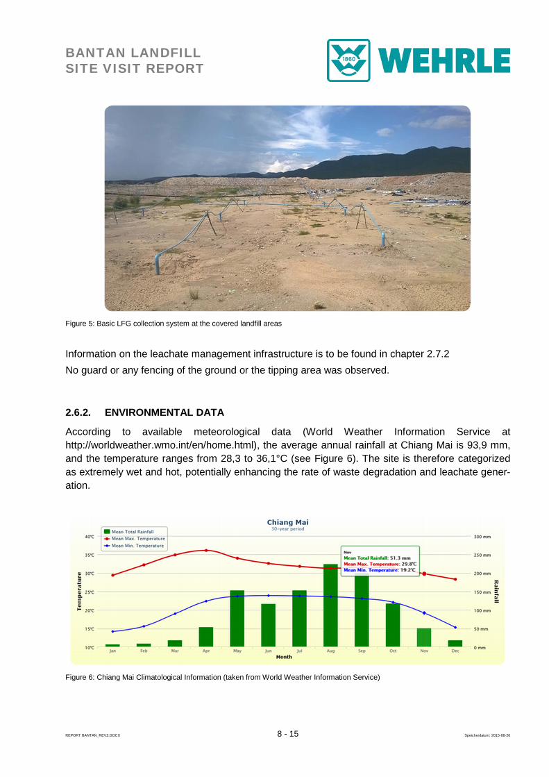
According to available meteorological data (World Weather Information Service at http://worldweather.wmo.int/en/home.html), the average annual rainfall at Chiang Mai is 93,9 mm, and the temperature ranges from 28,3 to 36,1°C (see Figure 6). The site is therefore categorized as extremely wet and hot, potentially enhancing the rate of waste degradation and leachate gener-ation.
Figure 6: Chiang Mai Climatological Information (taken from World Weather Information Service)
BANTAN LANDFILL SITE VISIT REPORT
REPORT BANTAN_REV2.DOCX 9 - 15 Speicherdatum: 2015-08-26
2.6.3. WASTE DEPTH
No data were provided. Site observations during the site visit are indicating a waste depth of ap-proximately 24m in the closed cells.
2.6.4. WASTE PLACEMENT
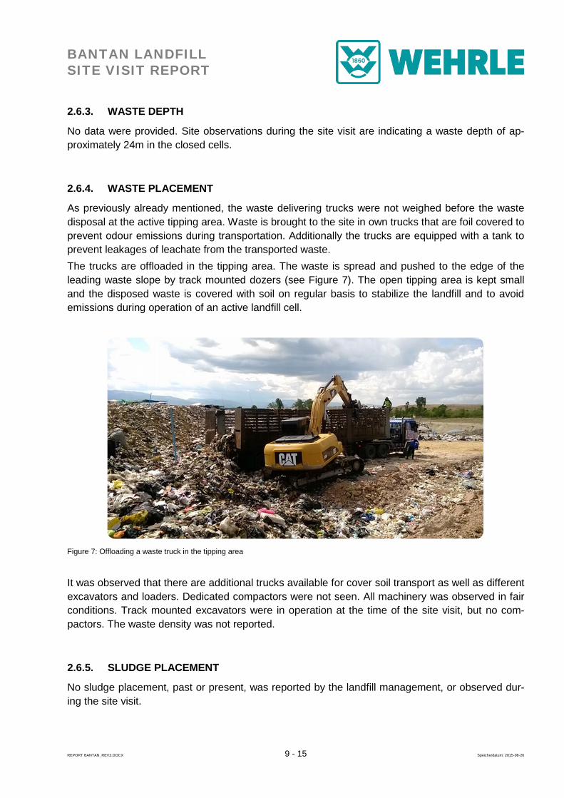
As previously already mentioned, the waste delivering trucks were not weighed before the waste disposal at the active tipping area. Waste is brought to the site in own trucks that are foil covered to prevent odour emissions during transportation. Additionally the trucks are equipped with a tank to prevent leakages of leachate from the transported waste. The trucks are offloaded in the tipping area. The waste is spread and pushed to the edge of the leading waste slope by track mounted dozers (see Figure 7). The open tipping area is kept small and the disposed waste is covered with soil on regular basis to stabilize the landfill and to avoid emissions during operation of an active landfill cell.
Figure 7: Offloading a waste truck in the tipping area
It was observed that there are additional trucks available for cover soil transport as well as different excavators and loaders. Dedicated compactors were not seen. All machinery was observed in fair conditions. Track mounted excavators were in operation at the time of the site visit, but no com-pactors. The waste density was not reported.
2.6.5. SLUDGE PLACEMENT
No sludge placement, past or present, was reported by the landfill management, or observed dur-ing the site visit.
BANTAN LANDFILL SITE VISIT REPORT
REPORT BANTAN_REV2.DOCX 10 - 15 Speicherdatum: 2015-08-26
2.6.6. BASE LINING
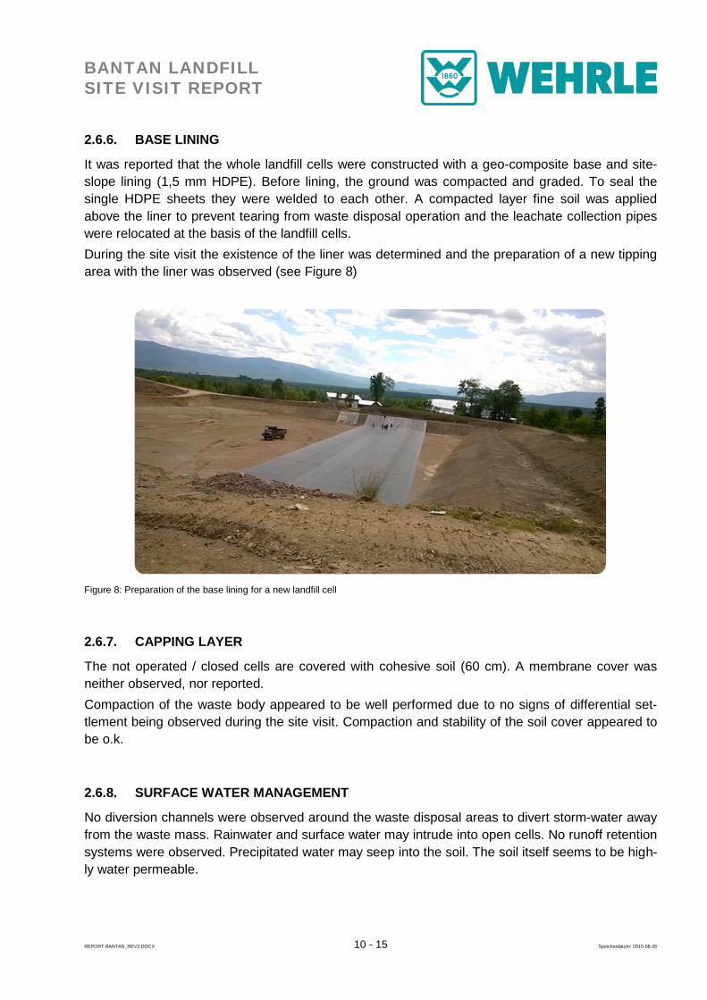
It was reported that the whole landfill cells were constructed with a geo-composite base and site-slope lining (1,5 mm HDPE). Before lining, the ground was compacted and graded. To seal the single HDPE sheets they were welded to each other. A compacted layer fine soil was applied above the liner to prevent tearing from waste disposal operation and the leachate collection pipes were relocated at the basis of the landfill cells. During the site visit the existence of the liner was determined and the preparation of a new tipping area with the liner was observed (see Figure 8)
Figure 8: Preparation of the base lining for a new landfill cell
2.6.7. CAPPING LAYER
The not operated / closed cells are covered with cohesive soil (60 cm). A membrane cover was neither observed, nor reported. Compaction of the waste body appeared to be well performed due to no signs of differential set-tlement being observed during the site visit. Compaction and stability of the soil cover appeared to be o.k.
2.6.8. SURFACE WATER MANAGEMENT
No diversion channels were observed around the waste disposal areas to divert storm-water away from the waste mass. Rainwater and surface water may intrude into open cells. No runoff retention systems were observed. Precipitated water may seep into the soil. The soil itself seems to be high-ly water permeable.
BANTAN LANDFILL SITE VISIT REPORT
REPORT BANTAN_REV2.DOCX 11 - 15 Speicherdatum: 2015-08-26
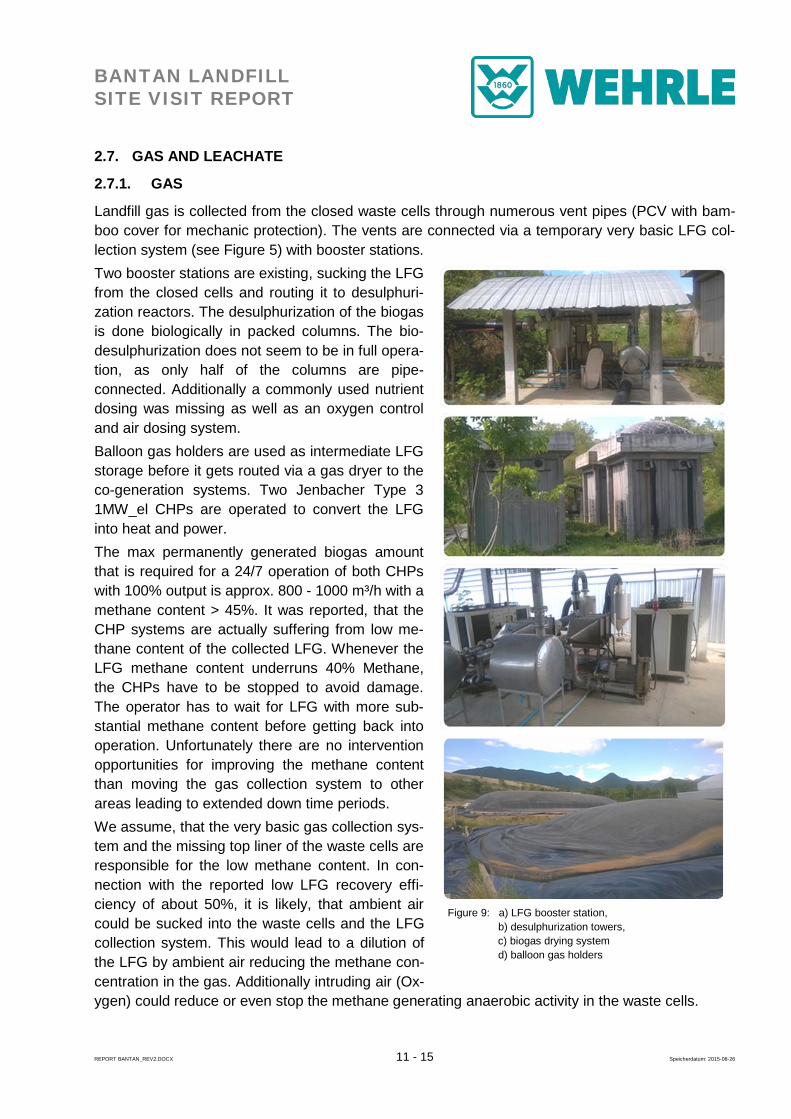
Figure 9: a) LFG booster station, b) desulphurization towers, c) biogas drying system d) balloon gas holders
2.7. GAS AND LEACHATE
2.7.1. GAS
Landfill gas is collected from the closed waste cells through numerous vent pipes (PCV with bam-boo cover for mechanic protection). The vents are connected via a temporary very basic LFG col-lection system (see Figure 5) with booster stations. Two booster stations are existing, sucking the LFG from the closed cells and routing it to desulphuri-zation reactors. The desulphurization of the biogas is done biologically in packed columns. The bio-desulphurization does not seem to be in full opera-tion, as only half of the columns are pipe-connected. Additionally a commonly used nutrient dosing was missing as well as an oxygen control and air dosing system. Balloon gas holders are used as intermediate LFG storage before it gets routed via a gas dryer to the co-generation systems. Two Jenbacher Type 3 1MW_el CHPs are operated to convert the LFG into heat and power. The max permanently generated biogas amount that is required for a 24/7 operation of both CHPs with 100% output is approx. 800 - 1000 m³/h with a methane content > 45%. It was reported, that the CHP systems are actually suffering from low me-thane content of the collected LFG. Whenever the LFG methane content underruns 40% Methane, the CHPs have to be stopped to avoid damage. The operator has to wait for LFG with more sub-stantial methane content before getting back into operation. Unfortunately there are no intervention opportunities for improving the methane content than moving the gas collection system to other areas leading to extended down time periods. We assume, that the very basic gas collection sys-tem and the missing top liner of the waste cells are responsible for the low methane content. In con-nection with the reported low LFG recovery effi-ciency of about 50%, it is likely, that ambient air could be sucked into the waste cells and the LFG collection system. This would lead to a dilution of the LFG by ambient air reducing the methane con-centration in the gas. Additionally intruding air (Ox-ygen) could reduce or even stop the methane generating anaerobic activity in the waste cells.
BANTAN LANDFILL SITE VISIT REPORT
REPORT BANTAN_REV2.DOCX 12 - 15 Speicherdatum: 2015-08-26
2.7.2. LEACHATE
Leachate is the liquid produced by contamination of water within the landfill site by a wide range of solutes resulting from the disposal and decomposition of waste (including organic and inorganic components) in landfills. The water content results from drainage of moisture from the original waste, water resulting from degradation, and infiltration of surface water (rainfall). Leachate can be highly contaminated and usually has a very low concentration of dissolved oxygen.
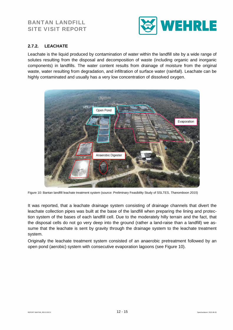
Figure 10: Bantan landfill leachate treatment system (source: Preliminary Feasibility Study of SSLTES, Thanomboon 2015)
It was reported, that a leachate drainage system consisting of drainage channels that divert the leachate collection pipes was built at the base of the landfill when preparing the lining and protec-tion system of the bases of each landfill cell. Due to the moderately hilly terrain and the fact, that the disposal cells do not go very deep into the ground (rather a land-raise than a landfill) we as-sume that the leachate is sent by gravity through the drainage system to the leachate treatment system. Originally the leachate treatment system consisted of an anaerobic pretreatment followed by an open pond (aerobic) system with consecutive evaporation lagoons (see Figure 10).
BANTAN LANDFILL SITE VISIT REPORT
REPORT BANTAN_REV2.DOCX 13 - 15 Speicherdatum: 2015-08-26
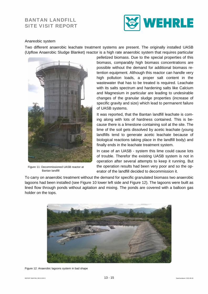
Anareobic system Two different anaerobic leachate treatment systems are present. The originally installed UASB (Upflow Anaerobic Sludge Blanket) reactor is a high rate anaerobic system that requires particular
pelletized biomass. Due to the special properties of this biomass, comparably high biomass concentrations are possible without the demand for additional biomass re-tention equipment. Although this reactor can handle very high pollution loads, a proper salt content in the wastewater that has to be treated is required. Leachate with its salts spectrum and hardening salts like Calcium and Magnesium in particular are leading to undesirable changes of the granular sludge properties (increase of specific gravity and size) which lead to permanent failure of UASB systems. It was reported, that the Bantan landfill leachate is com-ing along with lots of hardness contained. This is be-cause there is a limestone containing soil at the site. The lime of the soil gets dissolved by acetic leachate (young landfills tend to generate acetic leachate because of biological reactions taking place in the landfill body) and finally ends in the leachate treatment system. In case of an UASB - system this lime could cause lots of trouble. Therefor the existing UASB system is not in operation after several attempts to keep it running. But the operation results had been very poor and so the op-erator of the landfill decided to decommission it.
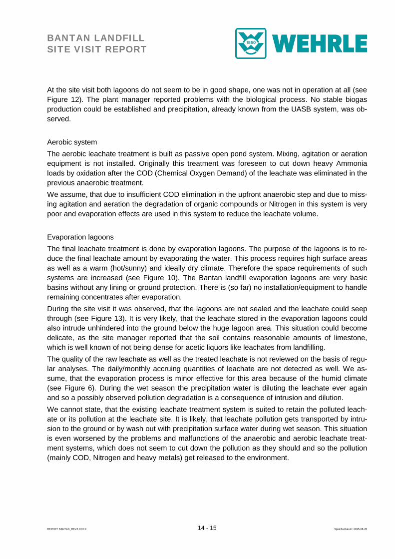
To carry on anaerobic treatment without the demand for specific granulated biomass two anaerobic lagoons had been installed (see Figure 10 lower left side and Figure 12). The lagoons were built as lined flow through ponds without agitation and mixing. The ponds are covered with a balloon gas holder on the tops.
Figure 12: Anaerobic lagoons system in bad shape
Figure 11: Decommissioned UASB reactor at Bantan landfill
BANTAN LANDFILL SITE VISIT REPORT
REPORT BANTAN_REV2.DOCX 14 - 15 Speicherdatum: 2015-08-26
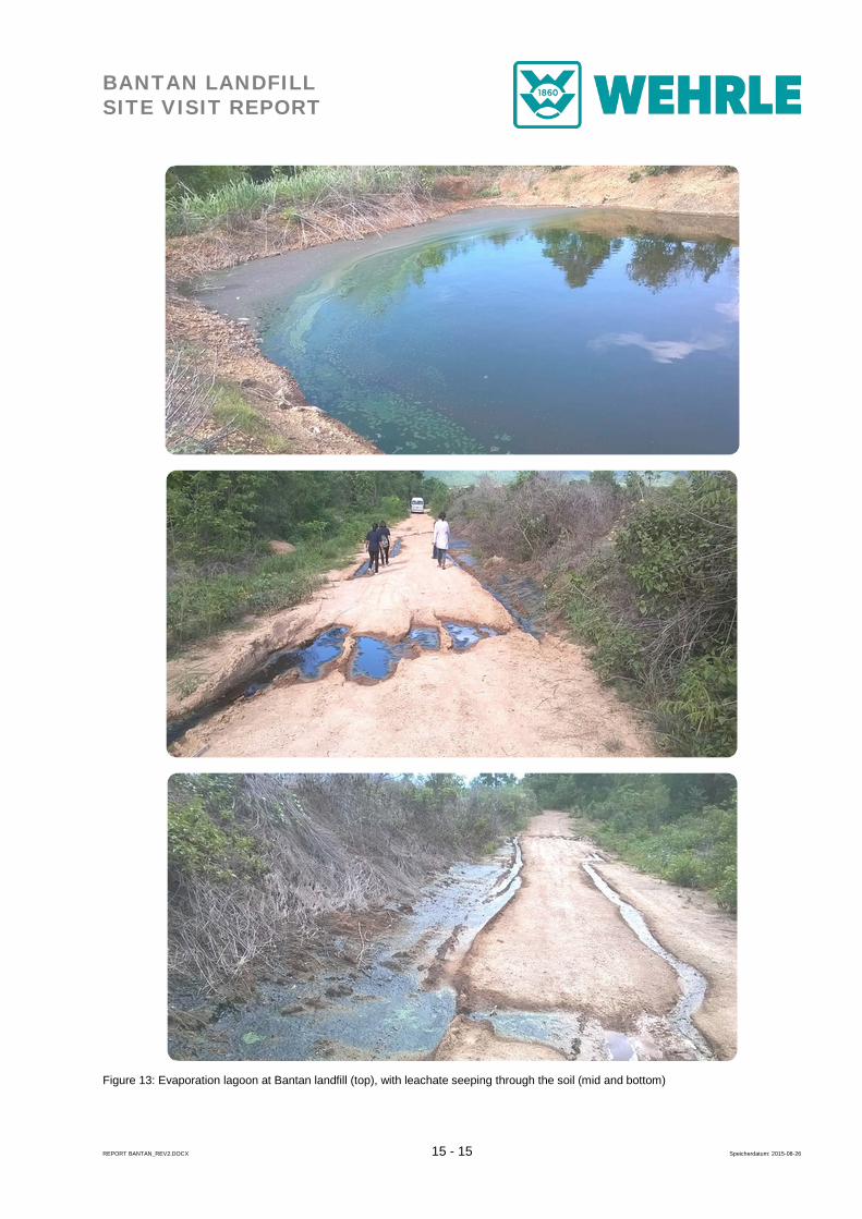
At the site visit both lagoons do not seem to be in good shape, one was not in operation at all (see Figure 12). The plant manager reported problems with the biological process. No stable biogas production could be established and precipitation, already known from the UASB system, was ob-served. Aerobic system The aerobic leachate treatment is built as passive open pond system. Mixing, agitation or aeration equipment is not installed. Originally this treatment was foreseen to cut down heavy Ammonia loads by oxidation after the COD (Chemical Oxygen Demand) of the leachate was eliminated in the previous anaerobic treatment. We assume, that due to insufficient COD elimination in the upfront anaerobic step and due to miss-ing agitation and aeration the degradation of organic compounds or Nitrogen in this system is very poor and evaporation effects are used in this system to reduce the leachate volume. Evaporation lagoons The final leachate treatment is done by evaporation lagoons. The purpose of the lagoons is to re-duce the final leachate amount by evaporating the water. This process requires high surface areas as well as a warm (hot/sunny) and ideally dry climate. Therefore the space requirements of such systems are increased (see Figure 10). The Bantan landfill evaporation lagoons are very basic basins without any lining or ground protection. There is (so far) no installation/equipment to handle remaining concentrates after evaporation. During the site visit it was observed, that the lagoons are not sealed and the leachate could seep through (see Figure 13). It is very likely, that the leachate stored in the evaporation lagoons could also intrude unhindered into the ground below the huge lagoon area. This situation could become delicate, as the site manager reported that the soil contains reasonable amounts of limestone, which is well known of not being dense for acetic liquors like leachates from landfilling. The quality of the raw leachate as well as the treated leachate is not reviewed on the basis of regu-lar analyses. The daily/monthly accruing quantities of leachate are not detected as well. We as-sume, that the evaporation process is minor effective for this area because of the humid climate (see Figure 6). During the wet season the precipitation water is diluting the leachate ever again and so a possibly observed pollution degradation is a consequence of intrusion and dilution. We cannot state, that the existing leachate treatment system is suited to retain the polluted leach-ate or its pollution at the leachate site. It is likely, that leachate pollution gets transported by intru-sion to the ground or by wash out with precipitation surface water during wet season. This situation is even worsened by the problems and malfunctions of the anaerobic and aerobic leachate treat-ment systems, which does not seem to cut down the pollution as they should and so the pollution (mainly COD, Nitrogen and heavy metals) get released to the environment.
BANTAN LANDFILL SITE VISIT REPORT
REPORT BANTAN_REV2.DOCX 15 - 15 Speicherdatum: 2015-08-26
Figure 13: Evaporation lagoon at Bantan landfill (top), with leachate seeping through the soil (mid and bottom)