artigo - a combination of on evaporation and membrane technique for landfill leachate treatment
TRANSCRIPT

8/3/2019 Artigo - A Combination of on Evaporation and Membrane Technique for Landfill Leachate Treatment
http://slidepdf.com/reader/full/artigo-a-combination-of-on-evaporation-and-membrane-technique-for-landfill 1/12
Proceedings Sardinia 2007, Eleventh International Waste Management and Landfill SymposiumS. Margherita di Pula, Cagliari, Italy; 1 - 5 October 2007
2007 by CISA, Environmental Sanitary Engineering Centre, Italy
A COMBINATION OF COGENERATION,EVAPORATION AND MEMBRANE
TECHNIQUE FOR LANDFILL LEACHATETREATMENT
E. GIUST, D. VISINTIN AND C. DEL PICCOLO
LED ITALIA Srl - Via Nuova di Corva 86/d, 33170 Pordenone, Italy
SUMMARY: The paper presents a solution realised to solve the problem of treatment of landfillleachate in a site in the north of Paris where two landfills are present: an old closed one and anew one still in operation. Two different types of treatment have been chosen to adapt thesolution to the specific characteristics of the two different leachates: Reverse osmosis for the oldstable leachate and double stage evaporation coupled with the LFG engines to improve theenergetic efficiency of motors on MSW landfill, for the new changing leachate. The paper willdescribe the dimensioning data, the performances of the plant and the results obtained after oneyear operation of one installation chosen among about 10 other working plants. An economicalevaluation of the Operative costs will be reported too.
1. INTRODUCTION
Landfill leachate treatment is an actual point of interest for many landfills managers mainly dueto the regulations that are changing in several countries and that impose more restrictions.
Traditionally there are several types of techniques applied to landfill leachate treatment:• Evaporation• Membranes techniques;• Biological treatment• Chemical-physical treatment.The right choice among these technologies relies on several aspects such as:• Quality and analytical characteristics of the leachate;• Expected quality of the treated stream;• Quantity to treat;• Availability of some energy sources.It is recognized (Tzahi Y. Cath et al., 2006) that evaporation and membranes processes are themost suitable one to remove TDS from a wastewater stream and that membranes are frequentlyused as pre-concentration to other steps.The present paper describes the technological choice that has been performed and consequentlyrealised in an operative treatment plant built in a landfill in the North of Paris in operation sinceabout 30 years.

8/3/2019 Artigo - A Combination of on Evaporation and Membrane Technique for Landfill Leachate Treatment
http://slidepdf.com/reader/full/artigo-a-combination-of-on-evaporation-and-membrane-technique-for-landfill 2/12
Sardinia 2007, Eleventh International Waste Management and Landfill Symposium
2. SITE DESCRIPTION
The landfill receives about 100000 ton/year of wastes, about 60% of which are municipal waste,38% industrial waste and 2% of waste from demolition activities. Two basins of about 4500 m3are used for the leachate collection (from both sites). 2.2 km of canalisation collect the about 800
Nm3/h of biogas that is produced with a methane content of about 45%.In 2001 a leachate treatment plant with an oxidation and a filtration through activated carbon
was installed, but after some years it wasn’t able no more to produce an effluent respecting thedischarge limits.
Actually about 10000 ton/year of new leachate as well as 10000 ton/year of old leachate needto be treated on site.
After analyses and laboratory tests, two different solutions for the two different leachates have been identified:
• Reverse osmosis for the “old” leachate from the closed landfill since this leachate is quitedilute and stable;
• Evaporation technology for the “new” leachate from the active landfill since this leachate is
developing and its characteristics are changing thus requiring a flexible type of treatment asevaporation is.
In Table 1, the characteristics of the leachate of the old site are reported. The average valueshave been obtained considering weighted values of the last years.
Table 1 - Raw leachate composition: old site
Minimum Maximum Average pH 8,0 8,4 8,1
Suspended solids mg/l 10 510 16Chemical Oxygen Demand (COD) mg/l O2 251 629 314
Biological Oxygen Demand (BOD) mg/l O2 10 38 13 BOD/COD 3% 6% 4%Conductivity S/cm 3796 6795 4295
Chlorides mg/l Cl 530 5500 960 NH 4+ mg/l N 102 234 118
Total Heavy metals mg/l 2,9 5,1 3,6
In Table 2, the characteristics of the leachate of the new site are reported. The average valueshave been obtained considering weighted values of the last 3 years, since the beginning of theleachate production.
Table 2 - Raw leachate composition: new site
Minimum Maximum Average pH 6,2 7,6 7,2
Suspended solids mg/l 53 150 137Chemical Oxygen Demand (COD) mg/l O2 290 1770 920
Biological Oxygen Demand (BOD) mg/l O2 198 1190 506 BOD/COD 68% 67% 55%Conductivity S/cm 1860 5505 4935
Chlorides mg/l Cl 284 5300 3300 NH 4+ mg/l N 31 185 118
Total Heavy metals mg/l 0,2 1,0 0,8

8/3/2019 Artigo - A Combination of on Evaporation and Membrane Technique for Landfill Leachate Treatment
http://slidepdf.com/reader/full/artigo-a-combination-of-on-evaporation-and-membrane-technique-for-landfill 3/12
Sardinia 2007, Eleventh International Waste Management and Landfill Symposium
In Table 2 it’s quite interesting to notice the ratio BOD/COD that is quite high and compatiblewith a new produced leachate. The ammonia and chlorides concentrations are also increasing asexpected.
The two parts of the plant are in reality connected: the RO concentrate is in fact father concentrated by the Evaporation plant to reduce the final volume to dispose at maximum, to
solve in this way also one aspect related to Reverse Osmosis technology enhanced by someliterature that is the relatively low concentration achievable through RO system (S. Hercule et al,2003), while the condensate of the evaporation is sent to the RO for final polishing beforedischarge.
On site, the biogas is recovered to feed a cogeneration plant and produce electrical energy thatis sold. ON site only one engine of 1 MW was installed. For this reason it was necessary toexploit both the cooling of engines and the exhaust combustion gases in order to obtain thenecessary 950 kW (thermal heat) for the evaporation process.
The landfill gas valorisation to produce electricity induces a loss of energy due to the enginescooling system and the combustion exhaust gases. In order to take benefit of this energy, twocompanies, LED ITALIA and GRS VALTECH developed a way of cogeneration throughleachate treatment (Hercule et al. (2005)). This process complements the evaporation technologyusing direct landfill gas, rather implemented on lower LFG production site (E. Cornu et al,2003).
2. FUNDAMENTALS OF THE CHOSEN TECHNOLOGIES
2.1 Reverse osmosis technique
The phenomenon of osmosis occurs when pure water flows from a dilute saline solution througha membrane into a higher concentrated saline solution.
The phenomenon of osmosis is illustrated in Figure 2.1. A semi-permeable membrane is placed between two compartments. “Semi-permeable” means that the membrane is permeable tosome species, and not permeable to others, if the membrane is permeable to water, but not to salt.And if this membrane is placed to divide a salty solution in one compartment and pure water inthe other compartment, the phenomenon that occurs is that the membrane will allow water to
permeate through it to either side and salt cannot pass through the membrane.
Figure 1: Reverse Osmosis concept

8/3/2019 Artigo - A Combination of on Evaporation and Membrane Technique for Landfill Leachate Treatment
http://slidepdf.com/reader/full/artigo-a-combination-of-on-evaporation-and-membrane-technique-for-landfill 4/12
Sardinia 2007, Eleventh International Waste Management and Landfill Symposium
With a high pressure pump, feed water is continuously pumped at high pressure to the membranesystem. Within the membrane system, the feed water will be split into a low-saline and/or
purified product; called permeate, and a high saline or concentrated brine, called concentrate or reject. A flow regulating valve, called a concentrate valve, controls the percentage of feed water that is going to the concentrate stream and the permeate which will be obtained from the feed.
The key terms used in the reverse osmosis / nanofiltration process are defined as follows.Recovery - the percentage of membrane system feed water that emerges from the system as
product water or “permeate”. Membrane system design is based on expected feed water qualityand recovery is defined through initial adjustment of valves on the concentrate stream. Recoveryis often fixed at the highest level that maximizes permeate flow while preventing precipitation of super-saturated salts within the membrane system.
Rejection - the percentage of solute concentration removed from system feed water by themembrane. In reverse osmosis, a high rejection of total dissolved solids (TDS) is important,while in nanofiltration the solutes of interest are specific, e.g. low rejection for hardness and highrejection for organic matter.
Passage - the opposite of “rejection”, passage is the percentage of dissolved constituents(contaminants) in the feed water allowed to pass through the membrane.
Permeate - the purified product water produced by a membrane system.The dimensions of the pores of the membranes used for Reverse osmosis are suitable to reject
the ions of a salty solution, thus producing a permeate with very low salinity and conductivity.
Figure 2: Flow inside an RO module
Flow - Feed flow is the rate of feed water introduced to the membrane element or membranesystem, usually measured in gallons per minute (gpm) or cubic meters per hour (m 3/h).Concentrate flow is the rate of flow of non-permeated feed water that exits the membrane
element or membrane system. This concentrate contains most of the dissolved constituentsoriginally carried into the element or into the system from the feed source. It is usually measuredin gallons per minute (gpm) or cubic meters per hour (m 3/h).
Flux - the rate of permeate transported per unit of membrane area, usually measured in gallons per square foot per day (gfd) or liters per square meter and hour (l/m 2h).
2.2 Evaporation technique
Evaporation technique is a physical separation of a solvent from a solution through heat supply;in wastewater treatment the solvent is water that is separated from a water-based solutioncontaining pollutants of different nature.
There are several techniques that can be used to perform this type of separation that can differ on:

8/3/2019 Artigo - A Combination of on Evaporation and Membrane Technique for Landfill Leachate Treatment
http://slidepdf.com/reader/full/artigo-a-combination-of-on-evaporation-and-membrane-technique-for-landfill 5/12
Sardinia 2007, Eleventh International Waste Management and Landfill Symposium
The type of energy source: electrical energy Steam Hot water
The type of circulation: Natural in which the liquid naturally flows inside the heat exchanger with low speed; Forced in which the liquid is pumped inside the heat exchanger by a pump at a certain rate
that gives the advantage of higher concentration factors, lower fouling phenomena andconsequently lower maintenance.
The type of technology: Mechanical vapour recompression: thermodynamically, it is the most efficient technique to
evaporate water. This process takes the vapour that has been evaporated from the product,compresses the vapour mechanically and then uses the higher pressure vapour as heatingmedium to perform the evaporation of the new inlet wastewater.
Single stage or multi stage hot water/steam: types of evaporators that use hot water/steamand cold water stream for evaporation/condensation. They can be single effect or multieffect: in case of multi effects evaporators the steam produced from evaporation in oneeffect is used to provide the heat to evaporate product in a second effect which ismaintained at a lower pressure. The multi-effects system lowers energy consumption butincreases the complexity of the plant and the setting of the working parameters.
Thermocompression: when steam is available at a certain pressures, it will often be possible to use thermo vapour recompression. In this operation, a portion of the steamevaporated from the product is recompressed by a steam jet venturi and returned to thesteam chest of the evaporator.
Heat pump: In a heat pump evaporator, the energy required for heating and condensing istransferred in a closed circuit by a refrigerant gas, normally Freon. This gas is heated by acompressor and pumped to the primary heat exchanger where heat is transferred to thewastewater. The wastewater is continually circulated from the boiling chamber through the
primary heat exchanger and back again. Upon return, flash evaporation takes place due tothe boiling chamber’s lower pressure and temperature relative to the wastewater. In theheat pump circuit, the Freon gas flows through an air cooled radiator and expands. As thegas expands, it cools down and then passes through the tubes of a condenser in the upper
part of the boiling chamber. Heat is absorbed from the wastewater vapour causingcondensation on the condenser tubes. This condensate is collected and flows to thedistillate tank as clean water. The gas returns to the compressor.
Evaporation produces two streams:
A treated major stream called condensate where all the suspended solids, heavy metals andsalinity are completely removed and most part of organics compounds are absent;
A concentrate that is a minor part of the inlet that contains all the pollutants.Some definitions that are useful while talking of evaporation are:
Yield - ratio between the quantity of condensate produced and the inlet.Concentration factor - parameter related to the yield that indicates how many times the
wastewater has been concentrated. For example a yield of 90% means that if 100 litres enter anevaporation system 90 litres are recovered as condensate that can be reused inside the productioncycle (in industries) or discharged if the reuse is not possible, and only 10 litres constitute thefinal residue. In this case the concentration factor is 10.
Boiling point rise - colligative property that corresponds to an increase in the boilingtemperature related to the presence of solutes in a solution.
8/3/2019 Artigo - A Combination of on Evaporation and Membrane Technique for Landfill Leachate Treatment
http://slidepdf.com/reader/full/artigo-a-combination-of-on-evaporation-and-membrane-technique-for-landfill 6/12
Sardinia 2007, Eleventh International Waste Management and Landfill Symposium
3. PROJECT DESCRIPTION
3.1 Old landfill
The treatment of landfill leachate by means of reverse osmosis requires an adequate conditioningof the leachate before entering the RO modules in order to preserve the plant performances. For this reason the plant is designed with: A pH adjustment and a degassing; Multimedia filtration; Chemical conditioning (antiscalant dosing) Cartridge safety microfiltration Multi stage double passage reverse osmosis.
3.1.1 PH adjustment and degassing
This step is performed in order to displace both ammonia equilibrium towards its salified form NH4+ that is more soluble in water and better rejected by RO and bicarbonates normally presenttransforming them in gaseous CO2. For this reason a degassing is necessary. The right pH valuehas been identified to be around 6: at this value in fact the chemical displacements of the 2equilibria are realized and at the same time no precipitation of organics occur (Wui Seng Ang etal., 2005).
3.1.2 Multimedia filtration
The first filtration step is carried out by a multimedia filtration bed specially suited for thequantitative removing of the suspended solids, with the minimization of the washing procedure;this filtration it is called “volume” filtration and it is realized with a multilayer (filtration mediawith different sizes and densities) filtration bed containing quartzite and anthracite. The second
filtration step is carried out by a multimedia filtration bed specially suited for the catalysis of theoxidation and the quantitative removal of heavy metals like iron and manganese. The presence of these two heavy metals can affect heavily the fouling process of the membranes and provide also
big problems during cleaning procedure. This second filtration step is also a safety filtration stepitself due to the strictly degree of filtration obtained by this media. The filtration bed iscomposed by quartzite and activated pirolusite.
3.1.3 Chemical conditioning
An antiscalant chemical is metered in order to limit scaling phenomena in the concentrationsteps.
3.1.4 Cartridge safety microfiltration
The landfill leachate is then entered in the cartridge filtration. The degree of filtration of thecartridge filters is 5 micron, in this way we can remove all the smaller particles that could beformed during chemical conditioning or that are possibly leaked through the multimedia filter.The filters cartridges can be easily substituted, this step is essential for the safety utilization of the reverse osmosis membranes. Special cartridge filters are utilized; they are obtained by themelt blow technology with two effective degree of filtration in series in the same cartridge
providing a volume filtration.
3.1.5 Multi stage double passage Reverse osmosis
Landfill leachate is now pressurized to the reverse osmosis modules of the first concentration

8/3/2019 Artigo - A Combination of on Evaporation and Membrane Technique for Landfill Leachate Treatment
http://slidepdf.com/reader/full/artigo-a-combination-of-on-evaporation-and-membrane-technique-for-landfill 7/12
Sardinia 2007, Eleventh International Waste Management and Landfill Symposium
passage, where nearly all dissolved salts and organic substances are held back, while pure water is forced through the semi permeable membranes.
The plant is completely automatic and it is realized with a multi stage and double passageconfiguration in order to reach on one side high recovery and on the other an excellent quality of the permeate making it suitable for discharge.
The process conditions are strictly controlled by the utilization of field instrumentationcontrolled by the PLC. The flow rate produced by every membrane array and the inlet and outlet
pressure of every membrane array are controlled, in this way the system continuously evaluatesthe fouling degree of the membranes and automatically can provide the cleaning procedure of themembranes when necessary with suitable and tested chemicals (Tragardh (1989), Madaeni et al(2001), Tran-Ha (2005)) using the CIP (Cleaning in Place) systems installed.
The second passage for the permeate polishing is realized with one concentration stage.The RO plant is dimensioned for a capacity of 3 m3/h in order to have enough capacity also
for the treatment of the evaporators condensates from the new landfill for polishing beforedischarge. The quality of the permeate is reported in Table 3 at chp. 4. The RO plant works witha recovery of about 90%, producing about 2.7 m3/h of permeate and 0.3 m3/h of concentrate thatis sent to the evaporation plant.
3.2 New landfill
The choice of evaporation technology was made to meet the requirements of the dischargecriteria as well as to have a very flexible technology able to treat a developing stream and theconcentrate produced by the RO system. A second stage of evaporation allows a reduction of thevolume of final concentrate.
The yearly water balance is about 10000 m 3 per year. The designed feeding rate is thus 30
m3
/d.To take benefit of the energetic loss of landfill gas engines, a cogeneration plant wasdesigned. This plant improves the 1000 kW energetic potential of the engines cooling system.Thus, the hot water used to cool the engines circulates in the shell side of a plate exchanger,which re-heat the influent. Part of the heat is recovered also from the fumes of the engines.
Each treatment step is detailed in the paragraphs below.
Figure 2. Simplified flow-sheet of the evaporation plant for new leachate treatment

8/3/2019 Artigo - A Combination of on Evaporation and Membrane Technique for Landfill Leachate Treatment
http://slidepdf.com/reader/full/artigo-a-combination-of-on-evaporation-and-membrane-technique-for-landfill 8/12
Sardinia 2007, Eleventh International Waste Management and Landfill Symposium
The process line for the treatment of the leachate of the new landfill is: A pH adjustment and a degassing; First evaporation/concentration step: Hot water forced circulation evaporator Second evaporation/superconcentration step: scraped hot water superconcentrator
3.2.1 PH adjustment and degassing This step is performed in order to displace both ammonia equilibrium towards its salified form
NH4+ that is more soluble in water to limit its passage in the vapour phase (Berbenni et al, 1997)and bicarbonates normally present transforming them in gaseous CO2. For this reason adegassing is necessary.Working at an acidic pH (5-5.5) lowers also scaling phenomena that can happen with theincrease of concentration inside the boiling chamber.
3.2.2 First evaporation/concentration step
In Fig. 3 a process scheme of the evaporator EW 40000 FF is reported as reference for thedescription.
Figure 3. Simplified flow-sheet of the evaporation plant for new leachate treatment

8/3/2019 Artigo - A Combination of on Evaporation and Membrane Technique for Landfill Leachate Treatment
http://slidepdf.com/reader/full/artigo-a-combination-of-on-evaporation-and-membrane-technique-for-landfill 9/12
Sardinia 2007, Eleventh International Waste Management and Landfill Symposium
The liquid is sucked inside the boiling chamber of the evaporator EW 400000 FF by the vacuumcreated inside it (4-5 kPa) by the liquid ring pump coupled with the ejector that works withVenturi principle using air as motor fluid. A circulation pump sends the liquid from the bottomof the boiling chamber inside the shell and tube heat exchanger where it receives the necessaryneat from the hot water stream that circulates inside the heat exchanger. Once heated, the liquid
returns to the boiling chamber, where as a result of the vacuum, a portion of the liquidimmediately boils (flash evaporation). The vapour rises through the demister in order to dampthe droplets. Vapour is condensed against the U tubes of the heat exchanger. The steamcondensation is then performed by an air cooler mounted on the evaporator.
The vacuum system extracts the condensed distillate together with any incondensable gasesand sends them to a storage tank. The distillate and the concentrate are discharged through a
pump. All operations are controlled by a PLC.The hot water comes from the cogeneration plant, while the cold water for condensation come
from the air cooler mounted over the top of the evaporator.The EW 40000 unit works with a yield of about 93% producing about 2.5 tonyday of
concentrate that is sent to another concentration step for further concentration and reduction.
3.2.3 Second evaporation/superconcentration step
A second step of vacuum evaporation is set up to lower the volume of final residues. Theconcentrate produced by the first stage of vacuum evaporation feeds a scraped evaporator RW3000 FF under vacuum for the same reasons explained for the EW 40000 unit (see the processscheme on the figure 4).
Figure 4: Second step of evaporation: scheme of the scraped evaporator

8/3/2019 Artigo - A Combination of on Evaporation and Membrane Technique for Landfill Leachate Treatment
http://slidepdf.com/reader/full/artigo-a-combination-of-on-evaporation-and-membrane-technique-for-landfill 10/12
Sardinia 2007, Eleventh International Waste Management and Landfill Symposium
The lower part of the boiling chamber is made by a heating jacket heat exchanger. The heat is provided by the system used on the first stage of evaporation: a part of hot water, from theengines cooling system, flows into the heating jacket. The concentrate is evaporated through heatdiffusion of the exchanger walls. A very efficient scraping Archimedes screw, driven by anelectric motor reducer, allows an efficient stirring and the cleaning of the exchanger walls and
allows to treat effluents with very high solids content and to produce a semi-solid concentrate.The temperature of evaporation is ranging between 35 and 45 °C for a residual pressure of 5 – 6kPa. The steam produced by the evaporation of concentrate is condensed on the air cooler mounted on the fist evaporator. The condensate is collected together with the one of the EW andtreated by the RO. A centrifugal pump coupled to an ejector assures the vacuum in the boilingchamber.
The evaporation process is conducted on batch run basis. The operating cycle is fixed by thelevel control in the boiling chamber. At the end of each cycle, the concentrator is stopped andresidues are discharge by rising and bending the chamber. The final concentrate is moved alongthe boiler chamber by the Archimedes screw.
Temperature sensors are used to control the evaporation process and the amount of heattransfer, in association with the flow rate sensor.Thus the global volume of residue is lowered, as a function of dry solids limits into theevaporator. The RW unit works with a yield of about 80-85% producing a final concentrate todispose of about 0.3 ton/day with a total solid content of approximately 70-75%.
4. RESULTS AND DISCUSSION
4.1 Qualitative and quantitative results
The plant was commissioned beginning of 2006: after one year operation no relevant episodeshappen both from process point of view and from electromechanical point of view.
Due to the interconnection of the 2 plants, the evaporation units and the RO unit, only 2streams come out as output: the RO permeate for discharge and the RW concentrate for finaldisposal.In Table 3 the quality of the permeate is reported as well as the limits fir discharge imposed bythe authorities.
Table 3 Quality of the final permeates and limits for discharge
Permeate Limits
pH 5,5 -Suspended solids mg/l <2 5
Chemical Oxygen Demand (COD) mg/l O2 <30 100 Biological Oxygen Demand (BOD) mg/l O2 <5 20
Conductivity S/cm 30 -Chlorides mg/l Cl <1,0 -
NH 4+ mg/l N <0,5 15
The permeate produced is characterized by a higher quality than the one required for discharge
with a reduction of more than 99% for the salinity (conductivity) and of about 97% for theorganic compounds (COD).
8/3/2019 Artigo - A Combination of on Evaporation and Membrane Technique for Landfill Leachate Treatment
http://slidepdf.com/reader/full/artigo-a-combination-of-on-evaporation-and-membrane-technique-for-landfill 11/12
Sardinia 2007, Eleventh International Waste Management and Landfill Symposium
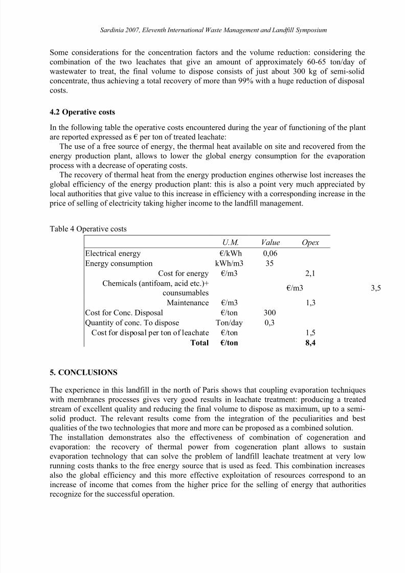
Some considerations for the concentration factors and the volume reduction: considering thecombination of the two leachates that give an amount of approximately 60-65 ton/day of wastewater to treat, the final volume to dispose consists of just about 300 kg of semi-solidconcentrate, thus achieving a total recovery of more than 99% with a huge reduction of disposalcosts.
4.2 Operative costs
In the following table the operative costs encountered during the year of functioning of the plantare reported expressed as € per ton of treated leachate:
The use of a free source of energy, the thermal heat available on site and recovered from theenergy production plant, allows to lower the global energy consumption for the evaporation
process with a decrease of operating costs.The recovery of thermal heat from the energy production engines otherwise lost increases the
global efficiency of the energy production plant: this is also a point very much appreciated bylocal authorities that give value to this increase in efficiency with a corresponding increase in the
price of selling of electricity taking higher income to the landfill management.
Table 4 Operative costs
U.M. Value OpexElectrical energy €/kWh 0,06Energy consumption kWh/m3 35
Cost for energy €/m3 2,1Chemicals (antifoam, acid etc.)+
counsumables €/m3 3,5
Maintenance €/m3 1,3Cost for Conc. Disposal €/ton 300Quantity of conc. To dispose Ton/day 0,3
Cost for disposal per ton of leachate €/ton 1,5Total €/ton 8,4
5. CONCLUSIONS
The experience in this landfill in the north of Paris shows that coupling evaporation techniques
with membranes processes gives very good results in leachate treatment: producing a treatedstream of excellent quality and reducing the final volume to dispose as maximum, up to a semi-solid product. The relevant results come from the integration of the peculiarities and bestqualities of the two technologies that more and more can be proposed as a combined solution.The installation demonstrates also the effectiveness of combination of cogeneration andevaporation: the recovery of thermal power from cogeneration plant allows to sustainevaporation technology that can solve the problem of landfill leachate treatment at very lowrunning costs thanks to the free energy source that is used as feed. This combination increasesalso the global efficiency and this more effective exploitation of resources correspond to anincrease of income that comes from the higher price for the selling of energy that authoritiesrecognize for the successful operation.

8/3/2019 Artigo - A Combination of on Evaporation and Membrane Technique for Landfill Leachate Treatment
http://slidepdf.com/reader/full/artigo-a-combination-of-on-evaporation-and-membrane-technique-for-landfill 12/12
Sardinia 2007, Eleventh International Waste Management and Landfill Symposium
REFERENCES
Berbenni P., Pollice, A., Fedrigoni, F. & Ceresi, G. (1997) : The vacuum evaporation process for landfill leachate treatment. Sardinia 1997, Sixth International landfill Symposium , CISA
publisher, Cagliari.
Cornu E., Ballot J., Bentounès N., Pernot H., and Hercule S. (2003) : Leachate treatment usinglandfill biogas. Proceedings Sardinia 2003, Ninth International landfill Symposium , CISA
publisher, CagliariHercule S., Taramini V., Samat P., Giust E., Biquillon R. (2005) : Cogeneration and evaporation:
an example of leachate treatment. Proceedings Sardinia 2005, Tenth International landfill Symposium , CISA publisher, Cagliari.
Hercule S., Cornu E., Ballot J., Coquant C., Dumesnil C. and Lebourhis D. (2003) : Review of in-situ leachate treatment plant : 3 case studies in France. Proceedings Sardinia 2003, Ninth
International landfill Symposium , CISA publisher, Cagliari.Madaeni, S.S., Mohammadi, T., Moghadam, M.K., 2001. Chemical cleaning of reverse osmosis
membrane. Desalination 134, 77–82.Tragardh, G., 1989. Membrane cleaning. Desalination 71, 325–335.Tran-Ha, M.H., Santos, V., Wiley, D.E., 2005. The effect of multivalent cations on membrane-
protein interactions during cleaning with CTAB. J. Membr. Sci. 251, 179–188.Tzahi Y. Cath, Amy E. Childress, Menachem Elimelech (2005): Osmosis: Principle, applications
and recent developments, Journal of Membrane Science , Elsevier.Wui Seng Ang, Sangyoup Lee, Manechem ELimelech (2005): Chemical and physical aspects of
cleaning of organic- fouled reverse osmosis membranes, Journal of Membrane Science ,Elsevier.