international journal of chemtech research - …654-665).pdf · international journal of chemtech...
TRANSCRIPT

International Journal of ChemTech Research CODEN (USA): IJCRGG ISSN: 0974-4290
Vol.7, No.2, pp 654-665, 2014-2015
ICONN 2015 [4th -6th Feb 2015]International Conference on Nanoscience and Nanotechnology-2015
SRM University, Chennai, India
Mechanical properties and fracture characteristics of ASTMA335 P91 steel used in boiler materials.
Maridurai T1, M.Syed Zameeruddin2*, Sandhyarani Biswas3
1Mechanical Engineering, Budelkhand University, Jhansi, India2Mechanical Engineering, SRM University, Chennai, India
3Principal, Budelkhand College, Jhansi, India
Abstract : Maximizing the efficiency of the power boilers generally requires operation atthe highest possible temperatures and steam pressures. In turn these most aggressiveoperating conditions require the use of higher strength materials than were typically used forthe construction of the power plants. This situation has increased the interest in the issuesrelated to the processing andthefabrication of alloys such as 90Cr-1Mo-V steels. Of thesesteels, the modified 9Cr-1Mo steel known as P91/T91 or, in Europe as X10CrMoVNb9-1,has been used in a wide range of industrial applications. In addition to the improved roomtemperature tensile strength, the modified variant also has increased creep strength, lowerductile –brittle transitiontemperatures and higher energy. The present study concerned withthe hot tensile properties of SA welded P91 material. The welding was carried out on a 406mm diameter, 53mm thick wall pipe by using root pass of TIG welding and subsequentpasses of SMAW and SAW. This study examines the effect of the tensile test temperatureranging from 400◦C to 700 ◦ C on the tensile properties of the P91 SA-weldment. The hottensile properties of SA welded P91 compared with the SMA welded P91 steel. The fracturesurfaces of the hot tensile & impact specimens were examined under Scanning electronmicroscope and fractographic studies were made. An attempt has also been made to evaluatethe mechanical strength of the weldment and microstructural characteristics of the differentregions in the weldment to correlate fractography features with tensile and impact strength.Key words: tensile,ductile, SMAW, SAW P91 X20.
1. Introduction:
Cr-Mo ferritic steels are widely used infossil power plant for the structure and piping systems due totheir creep strength and moderate oxidation resistance up to 650 ◦c. the 90Cr-1Mo steel is one of the best alloysin the family of Cr-Mo steels for elevated temperature applications1,2,3,4,5. With ever increasing the demand ofhigh efficiency in the power generation industry, the operation temperature is steadily increasing. Themodified90Cr-1Mo steel is a relatively new structural alloy that was originally developed in the steam generatorindustry. With minor addition of Nb & V elements in the 90Cr-1Mo steel, the long term creep strength of thesteel can be further improved. P91 is primarily used in the normalized and tempered condition. During the heattreatment, a fine dispersion of Nb(C,N) and M22C6 is precipitated. Through the mechanism of precipitationstrengthening, this gives rise to the enhanced mechanical properties. Welding of Cr-Mo ferritic steels play a

M.Syed Zameeruddin et al /Int.J. ChemTech Res.2014-2015,7(2),pp 654-665. 655
crucial role in the power and the petroleum industries, and has been extensively and studied in recent years.Considerable effort went in the development of 90Cr-1Mo-V steel consumables to optimize strength andtoughness of the weldment.
Welded joints are used as structural parts of boilers, pressure vessels, piping, tunings and otherequipment working at high temperatures. In addition to these properties, the welded structure must be safeenough during the sudden starts or interruption of its operation. Therefore welded joints of heat resistance steelsmust have appropriate Impact properties and resistance against brittle failure6,7, the stringent design,construction and operational requirements of nuclear plantsdemand consistency of the material behavior. This isreflected in the more restricted composition and property specification of the normalized and tempered 90Cr-1Mo steel currently adopted by the UK nuclear industry which meets the broader international standards 8,9,10.The weld abilityof P91 steels is very good. Due to the high alloying content, a relatively high preheatingtemperature (200-350◦C) must be used. The development of the suitable welding filler metal of the similar typewhich can employed in the SMAW, GTAE and SAW welding methods11,12. Current trends in the design of largepressure vessles require massive sections that operate under high stresses at high temperature. To attain goodthrough section fracture toughness values at higher yield strength that are required for such components, thesteel needed to be used must possess higher hardenability, and greater heat treatment potentials. Toughnesscharecterization is one of the important parameters which plays a vital role in determining the performance andlife of the materials under the given service conditions. Toughness characterization is done by impact energytest, fracture toughness test(plane stress fracture toughness test) (K1C) test15.
The present investigation has been carried out to assees hot tensile properties and fracture toughnessscharacteristics of P91 weldment. SA welding was done on a 406 mm diameter & 53 mm thick wall pipe. Thisstudy examines the effect of tensile test temperatures ranging from 400 to 700 ◦c on the tensile properties of theSA weldment. The hot tensile properties of SA welded P91 compared with the SMA welded P91 steel. Thefracture surfaces of the hot tensile and impact testes were examined by scanning electron microscope (SEM)and fractographic studies were made. An attempt has also been made to evaluate the mechanical properties ofthe weldment and microstructural characteristics of the different regions in the weldment.
2. Experimental details:
In the current investigation, joining of SA 335 P91 by SMA welding process was carried and theresultant weldment subjected to mechanical and metallurgical studies. This study examines the effect of thetensile test temperatures ranging from 400 to 700 ◦c on the tensile properties of SAW and SMAW welded P91steel. Fractographic studies were done by Scanning electron microscope to know the characteristics of thefracture surface. The impact testing of SAW weldment was done. Also the microstructural evaluation of theweldmentas hardness testing was carried out.
2.1 Materials Used:
The material chosen for investigation is SA 335 P91, low alloy ferritic steel. The original dimension ofthe pipe was ø460 mm × 53 mm ×300 mm and welded by SAW. The dimensions of the pipe used for SMAWwas ø 120 mm ×12 mm thick.
2.2 Chemical analysis:
Chemical analysis was carried out on the material chosen for investigation (P91) as per standardizationof ASTM E-1086. The experimental result shows that composition of the chosen material matches the ASTMstandard chemical composition value. The table gives the chemical composition (%) of the P91 as per theASTM standards and also the experimental analyzed result.

M.Syed Zameeruddin et al /Int.J. ChemTech Res.2014-2015,7(2),pp 654-665. 656
Table 1:chemical composition SA 335 P91.
Table.2:Chemical composition of SAW welded P91.
2.3 Welding consumables:
The following table gives chemical composition of the welding consumables available forSMAW,GTAW and GMAW.
Table 3. Chemical composition of welding consumables.
2.4 Welding flux:
Flux, marathon 543 is a highly basic agglomerated flux specially designed for SAW with AWS E B9wire. When used in combination with AWS EB9, Marathon 543 yields a weld deposit that is chemicallybalanced to insure optimum mechanical properties, including creep resistance. Welding characteristics areexcellent with good wetting and easy slag removal. Marathon 543 is metallurgical neutral.
2.5 Welding joint details:
The single ‘U’ edge preparation was used for SA- welding of ø 460 mm, 53 mm thick pipe. The single‘V’ edge preparation was used for SMA-welding of ø 120 mm, 12 mm thick pipe.
Table 4: Details of edge preparation

M.Syed Zameeruddin et al /Int.J. ChemTech Res.2014-2015,7(2),pp 654-665. 657
2.6 welding procedure:
Table 5: GTA welding parameters for root pass (Weld metal deposit 2.5 mm)
Table 6: SMA Welding Parameters for further two passes (Weld metal deposit 10mm)
Table 7: SA welding parameters
The two pipes were preheated and checked with thermal chalks to achieve a minimum temperature of100 ◦ C. GTAW process was used for tackling the pipes and weld deposit thickness was 2.5 mm. particularattention was paid to the quality of tack weld welds were dressed by grinding to facile proper fusion where theroot run completed. Back purging by argon was done to prevent oxidation inside the pipe. The SMAW processwas used for the further two passes and the weld metal deposit was 10 mm. the SMAW stick electrodes afterbaking were stored in a portable oven at 150◦C.preheating was done using producer gas burners for temperatureof 220◦C and was maintained before and during the course of the welding. The temperature was checked usingthermal chalks. Inter pass temperature was controlled between 230◦- 350◦C and when temperature exceeded themaxiumum, welding was stopped and resumed afterafter the temperature dropped to 230◦C. further passes weredone by using the SAW. Preheating and interpass temperature were manited as same. On completion of weldingthe joints were given post heating at 300◦C/2 hours by enclosing thermal blankets. Radigraphic inspection wasdone after welding, then gring of capping passes. Then the weld metal was subjected to PWHT of 750◦C for 260minutes. Preheating and PWHT procedure is given in fig 3.3

M.Syed Zameeruddin et al /Int.J. ChemTech Res.2014-2015,7(2),pp 654-665. 658
Fig 3.3 : Preheating and PWHT Procedure
Table 8: Heat treatment Procedure (Preheating and PWHT
3. Testing:
3.1 Tensile Testing:
Both the base metal and weldment were subjected to tensile testing. ASTM E8M was used for the basemetal tensile testing. The transverse tensile specimens of weldment were prepared in the following dimensions20 X 20 mm as per the standard AWS B4.0-98. All weld metal tensile test was also done as per the standard.Two specimens of transverse tensile were taken from the face side of the weldment. Also two specimens weretaken from the root side for tensile testing.
3.2 Hardness Testing:
Hardness survey was done by using Vickers hardness tester with 10Kg load, The indents were made inBase material, weld metal and Heat affected zone.
VHN=1.85P/L2
Where, P – Load in Kg, L – diagonal length in mm.
The impression appears as a dark square on a light background. The measurements are taken across thediagonals of the square, and the hardness value corresponding to the readings is obtained from a chart orcalculated by a simple formula.
3.3 Impact Testing:
This test measure the resistance of the metal to fracture in the presence of a sharp notch also callednotched-bar impact test. Minimum impact values are specified in many codes and specifications for ferriticsteels, because some of them fail by brittle fracture in service, even though they exhibit normal properties as

M.Syed Zameeruddin et al /Int.J. ChemTech Res.2014-2015,7(2),pp 654-665. 659
determined from the standard tensile test. Even failure is especially severe when the material used in a notchedcondition.
Notched conditions include restraint due to deformation in directions perpendicular to the major stress,multi-axial stress, and stress concentrations. The energy values determine the variation of impact strength withtemperature and arriving at the transition temperature. They are not useful for engineering design calculations.There are several impact tests among which charpy-V notch, is well known. To carry out the test, the specimenis paced in a vice of an impact testing machine. A pendulum, swinging on ball allowed to strike the specimen.The striking energy is absorbed in fracturing the specimen, is indicated by pointer. The impact test values areexpressed in joules(J). in this present investigation, impact specimens were taken from the face side and rootside of the weldment.
3.4 Side Bend Testing :
The bend test is a simple and inexperience quantitative test that can be used to evaluate both theductility and soundness of the material . the bend test coupon was prepared according to AWS specification.This test was conducted on UTM with 6.66t material at 180⁰ bend. The transverse side bend test is good atrevealing lack of side wall fusion. The test coupon is said to pass only when it does not have discontinuity inweld.
3.5 Hot Tensile Testing:
This study examines the effect of temperature ranging from 400 to 700⁰C on the tensile test propertiesof a SAW weld of modified 9Cr-1Mo ferric steel. Hot tensile testing was performed in an UTN-60 testingmachine. Isothermal tensile test on SAW welded transverse tensile specimens of the six of 12.5 X 6 mm werecarried out at the temperature of 400⁰C, 500⁰C, 600⁰C, and 700⁰C. the specimens were selected from both theface and root side of the weldment. The present investigation also aims on studying the SMAW welded P91 inthe temperature range of 400 to 700⁰C.
3.6 SEM Analysis of Fracture Surface:
SEM examination of the fracture surfaces of all the hot tensile and impact tested specimens werecarried out then the fractographs were compared together.
4. Results and Discussion:
4.1 Tensile Resting:
The transverse tensile tensiletest results of the weld joint by SAW, all weld tensile and tensile testresults of the base metal are shown in the table 9 and 10. Two test coupons of the weld were evaluated as perstandard. The investigated values of all tension test results are within the requirements of ASTM A213. In eachcase of face side transverse tensile the failure was observed in wed metal and the reason behind the failure isbecause of the coarse martensite and δ ferrite in the weld metal. Weld metal side failures were observed in rootside tensile test because less strength of the root pass weld metal of 21/4 Cr 1Mo. Because the tensile strengthof P22 material was less than that of the P91 base material and the weld metal. The investigated values of all thetransverse tensile test results are within the requirements of ASME SEC-IX.
Table.9. Transverse tensile test result of P91 SAW weldment
M.Syed Zameeruddin et al /Int.J. ChemTech Res.2014-2015,7(2),pp 654-665. 660
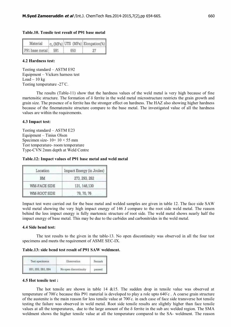
Table.10. Tensile test result of P91 base metal
4.2 Hardness test:
Testing standard – ASTM E92Equipment – Vickers harness testLoad – 10 kgTesting temperature -27◦C.
The results (Table-11) show that the hardness values of the weld metal is very high because of finemartensitic structure. The formation of δ ferrite in the weld metal microstructure restricts the grain growth andgrain size. The presence of α ferrite has the stronger effect on hardness. The HAZ also showing higher hardnessbecause of the finematensite structure compare to the base metal. The investigated value of all the hardnessvalues are within the requirements.
4.3 Impact test:
Testing standard – ASTM E23Equipment – Tinius OlsenSpecimen size- 10× 10 × 55 mmTest temperature- room temperatureType-CVN 2mm depth at Weld Centre
Table.12: Impact values of P91 base metal and weld metal
Impact test were carried out for the base metal and welded samples are given in table 12. The face side SAWweld metal showing the very high impact energy of 146 J compare to the root side weld metal. The reasonbehind the less impact energy is fully martensic structure of root side. The weld metal shows nearly half theimpact energy of base metal. This may be due to the carbides and carbonitrides in the weld metal.
4.4 Side bend test:
The test results to the given in the table-13. No open discontinuity was observed in all the four testspecimens and meets the requirement of ASME SEC-IX.
Table.13: side bend test result of P91 SAW weldment.
4.5 Hot tensile test :
The hot tensile are shown in table 14 &15. The sudden drop in tensile value was observed attemperature of 700◦c because this P91 material is developed to play a role upto 640◦c . A coarse grain structureof the austenite is the main reason for less tensile value at 700◦c. in each case of face side transverse hot tensiletesting the failure was observed in weld metal. Root side tensile results are slightly higher than face tensilevalues at all the temperatures, due to the large amount of the δ ferrite in the sub arc welded region. The SMAweldment shows the higher tensile value at all the temperature compared to the SA- weldment. The reason

M.Syed Zameeruddin et al /Int.J. ChemTech Res.2014-2015,7(2),pp 654-665. 661
behind the higher tensile value is due to the less δ ferrite in the weld metal and also failure was observed in basemetal region.
Table .14: Hot tensile test result of SA-welded P91 weldment
Table.15: Hot tensile test results of SMA-welded P91 weldment
4.6 Microstructural characterization:
The P91 base metal consists of tempered martensitic metal consists of tempered martensitic structureand finely distributed carbides and carbonitrides
Fig .1: Micrograph of the P91 base metal at 340 X Fig.2:Micrograph of HAZ at 340 X
(figure.1.). Figure.2 shows the HAZ microstructure of fine martensite with finely distributed carbides.The precipitates of these regions are probably M23C 6 and QX (Nb-V Carbonitrides).
Fig .3: Micrograph of the face Fig.4: Micrograph of the weld metalside weld metal (SAW) at 170X (SAW) 2 mm from the top at 170X
Micrograph of the SAW-weld face (figure.3) shows the martensite with δ- ferrite with finely distributedcarbides.

M.Syed Zameeruddin et al /Int.J. ChemTech Res.2014-2015,7(2),pp 654-665. 662
Figure.4 shows the finer martensitic structure which has taken in SAW welded region of -4 mm awayfrom the weld top. Finer martensite formed due to grain refinement of the multipass welding. The formation ofδ-ferrite in the weld metal microstructure during the solidification restricts the grain and grain size. However,martensite gradually losses its acicular feature because of the PWHT.
Fig.5: Micrograph of the weld meal Fig.6: The interface between GTAW &(SMAW) at 170 X SMAW WM at 170 X
The SMAW weld metal structure(figure.5) exhibits fine martensitic structure compare to the SAW weldmetal, this may be because of the low heat input which can accelerate the fast cooling rate.
Figure.6 shows the interface between TIG and SMAW.TIG weld metal consists of acicular ferritestructure due to the multipass welding effect. The figures 7 & 8 below micro photographs show the interfaceweld metal. The SAW shows the wider fusion boundary compare to the SMAW fusion boundary.
Fig. 7: The interfaces of SAW Fig.8: The interface SMAW weld metal at 170 Xweld metal at 170 X
Also coarse grain structure of HAZ is observed in the SAW welds side.
4.7 Fracture characterization studies:
The fracture appearance of SAA-welded face side hot tensile specimen fractured at 400◦C that hadtensile
Fig.9: SEMfractograph of SA-welded Fig.10: SEM fractograph of SA-weldedface side hot tensile at 400◦C face side hot tensile test at 500◦C
Strength of 515 MPa exhibits extensive dimple fracture with micro voids as shown in figure 9. Thefracture surface of the fracture surface of the SA-welded face side hot tensile fractured at 500◦C,
Shows dimple fracture with more number of micro voids (fig.10). Larger sizes of voids are observed inthe fracture surface of SA-welded face side hot tensile specimen tested at 700◦C exhibited a dimple appearancecharacteristic of micro void coalescence with grain boundary facets with smaller number of dimples(Fig.12).The facture surface of SAW root side hot tensile specimen tested at 400◦C shows a dimple

M.Syed Zameeruddin et al /Int.J. ChemTech Res.2014-2015,7(2),pp 654-665. 663
Fig.11 SEM fractograph of SA-welded Fig.12.SEM fractograph of SA-weldedface hot tensile test at 600◦C. face side hot tensile at 700◦C
Fig(13). The fracture appearance of SAW root Fig.14.SEM fractograph of SA-weldedside hot tensile specimen tested at 500 ◦C root side hot tensile at 500◦C
Fig.15 SEM Fractograph of Fig.16.SEM fractograph of SA-weldedSA-welded root side hot tensile at 600⁰C root side hot tensile at 700◦C
Fig.17. SEM fractograph of SMA- Fig.18.SEM fractograph of SMA-welded hot tensile at 400◦C welded hot tensile at 500◦C
Fig 19.SEM fractograph of SMA Fig .20.SEM fractograph of SMA-–welded hot tensile at 600◦C welded hot tensile at 700◦C

M.Syed Zameeruddin et al /Int.J. ChemTech Res.2014-2015,7(2),pp 654-665. 664
Fig.21.SEM Fractograph of SAW Fig.22.SEM fractograph of SAW weldedwelded face side impact specimen at RT. root side impact specimen at RT
Fracture with some cleavage facets(Fig.13).The fracture appearance of SAW rootside hot tensilespecimen tested at 500⁰C exhibits dimple fracture and micro voids with some cleavage facets (fig.14).Dimplefracture with micro voids coalescence is observed in the fracture surface of hot tensile tested at 600◦C (fig.15).
The fracture surface of hot tensile fractured at 700◦C shows mainly cleavage dominated fracture withsome dimple fractured area (fig.16). Dimple fracture with some cleavage facets are observed in SMA-weldedhot tensile specimen fractured at 400◦C and 500◦c (fig.17 and 18). Dimples and micro void coalescence withgrain boundary facets are observed in SMA-welded hot tensile tested at 600◦C (fig.19). Cleavage facetsdominated with small amount of dimples are observed in hot tensile specimen tested at 700◦C (Fig.20).(Fig.21and 22) show SEM fractographs of impact-fractured specimens. The fracture appearance of a SA-welded faceside fractured impact specimen that had impact energy of 131 j exhibits dimple fracture with some cleavagefacets.But root side fractured impact specimen that had impact energy of 79 J exhibits completely cleavagefacets.
5. Conclusion:
Major conclusions drawn from this study relating to the evolution of the microstructures, hot tensiletests and fracture characteristics of 9Cr-1Mo-V weldment are given below:
The base metal evolution has shown that the P91 steel chosen for the work has the composition withinthe specific limit. The mechanical properties, tensile strength, impact toughness and hardness are also meetingthe requirements.
Welding procedure or P91 pipe with root pass welding of GTAW and subsequent passes of SMAW andSAW were developed qualified as per the standard ASME SEC-IX.
The tensile properties of P91 weldment were measured at room temperature and temperature rangingfrom 400⁰C – 700⁰C. Root side tensile results are slightly higher than face side tensile values at all thetemperatures, due to the coarse martensitic and ᵟ ferrite in the sub arc welded region. The SMA-weldmentshows the higher tensile value at all the temperature compare to the SA-weldment, because of fine martensiticstructure with carbides in the weld metal.
From impact testing, it was observed that the base metal exhibits the highest toughness compared toweld metal of both root side and face side due to tempered martensite and globular carbides in the base metalmicrostructure.
From the hardness testing of the weldment, the weld zone registered the highest values ranging from228-236 HV10. Intermediate hardness values were observed in the HAZ region. The parent metal registered thehardness value of 206HV10.
Microstructural analysis using light optical microscope reveals the coarse martensite and carbides with ᵟferrite in the weld region. Base metal microstructure consists of tempered martensitic structure and finelydistributed carbides, and HAZ consists of martensite with finely distributed carbides.
Hot tensile specimens fractured ay 400⁰C – 700⁰C exhibits dimple fracture with micro voids. Somesmall amount of cleavage facets were observed in the specimen fractured at 700⁰C. the fracture appearance of aSA-weldment face side fracture impact specimen that had impact energy of 131 J exhibits dimple fracture with

M.Syed Zameeruddin et al /Int.J. ChemTech Res.2014-2015,7(2),pp 654-665. 665
some cleavage facets and root side fracture-impact specimen that had impact energy of 79J exhibits completelycleavage facets.
6. References:
1. Swindeman, R.W., Santella, M.L., Maziasz, P.J., Roberts, B.W., Coleman, K., Issues in replacing Cr-Mo Steels and Stainless steel with 9Cr-1Mo-V Steels, Inter-national Journal of Pressure Vessels andPiping, 2004, 81,507-512.
2. Kspiradek, R., Bauer., and Zeiler, G., microstructural changes during the creep deformation of 9%chromium steel, materials for advanced power engineer, Kluwer Academic publishers,Dordrecht, 1994,251-262.
3. Eva-Lena Bergquist., Esab, A.B., Goteborg, Consumables and welding modified 9Cr-1Mo Steel,svetsaren no.1-2,Central Laboratories in Goteberg,Sweden,1999, 22-25.
4. Knott, J.K., A Genral Introduction to Fracture Mechanics, 1976, 20-21.5. Laha, K.,.Chandravathi, K.S., Rao, K.B.S., Mannan, S.L., Hot tensile properties of simulated heat
affected zone microstructure of 9Cr-1Mo weldment”,Internationl journal of Pressure Vessels AndPiping 62, 1995, 303-311.
6. Anon., Guide to the welding and weldability of Cr-mo and Cr-MoV heat resitingteels”,IIW Doc.IXG-319, 1986, 43-44.
7. Regev, M., Investigation of Microstructure,Mechanical and Creep properties of weldments betweenT91 and T22 Steels”, Welding Journal, 1996, 261s.
8. Khare, K., Ferritic Steels for High-temperature Applications ,Conference proceedings ASM, MetalsPark Ohio,6-8, 1981, 85-86.
9. Carl, Lundin, D., A Literlature Review on Characteristics of High Temperature Ferritic Cr-Mo steelsand weldments”,WRC Bulletin 454, 2000, p1.
10. David Broek., Elementary Engineering Fracture Mechanics, Vorboff International, 1974, 46-47.11. Patron, V.Z., Morozov, E.M., Elastic Plastic Fracture Mechanics, Mir Publishers Moscow,1978, 26-
27.12. Dittrich, S., Heuser, H. ,”Welding of T/P 91 Steel with optimized Filler Metal Addition”,Technical
Information HC/4-105,Bohler Thyssen Welding Institute, 7-28.13. Blame, R., Leich, K.E., Heuser, H., and Meyer, F.W., Welding of modified 9% Cr Steel, Technical
Information HC/4-105,Bohler Thyssen Welding Institute, 1-6.14. 14.Heuser, H., GTA-and SA –welding of the 9%Cr-steel T91/P91, the 73rd Annual AWS-convention,
March 24,Chicago 1992.15. Sperko Engineering Services,Inc. Welding “Grade 91”Alloy Steel, 2005, 2-4.
*****