failure of p91 pipe
TRANSCRIPT
ORNL/TM-2006/1
INVESTIGATION OF A MODIFIED 9CR-1MO (P91) PIPE FAILURE April 2006 R. L. Klueh and J. P. Shingledecker
This report was prepared as an account of work sponsored by an agency of the United States government. Neither the United States government nor any agency thereof, nor any of their employees, makes any warranty, express or implied, or assumes any legal liability or responsibility for the accuracy, completeness, or usefulness of any information, apparatus, product, or process disclosed, or represents that its use would not infringe privately owned rights. Reference herein to any specific commercial product, process, or service by trade name, trademark, manufacturer, or otherwise, does not necessarily constitute or imply its endorsement, recommendation, or favoring by the United States government or any agency thereof. The views and opinions of authors expressed herein do not necessarily state or reflect those of the United States government or any agency thereof.
ORNL/TM-2006/1
Materials Science and Technology Division
INVESTIGATION OF A MODIFIED 9CR-1MO (P91) PIPE FAILURE
R. L. Klueh and J. P. Shingledecker
Date Published: April 2006
Prepared by OAK RIDGE NATIONAL LABORATORY
Oak Ridge, Tennessee 37831-6283 managed by
UT-BATTELLE, LLC for the
U.S. DEPARTMENT OF ENERGY under contract DE-AC05-00OR22725
CONTENTS
Page LIST OF FIGURES........................................................................................................................... v ABSTRACT ................................................................................................................................... vii INTRODUCTION............................................................................................................................. 1 Failure Description........................................................................................................................................ 1 Metallography and Hardness ........................................................................................................................ 2 DISCUSSION................................................................................................................................... 8 ACKNOWLEDGEMENTS.............................................................................................................. 10 REFERENCES ............................................................................................................................... 10
iii
LIST OF FIGURES
Figure Page
1 Picture of elbow labeled to show where metallography specimens were obtained…………. 1 2 Base metal microstructure in unfailed leg of the elbow…………………………………….. 2 3 Low-magnification photomicrograph of the weldment of the P91 tube to the elbow………. 3 4 Martensite microstructure of the (a) elbow (upper left of Fig. 3) and (b) the weld metal that formed the weld from the elbow to the pipe (center of Fig. 3)…………………………. 3 5 Base metal of pipe (a) inside the elbow away from the weld (lower left of Fig. 3) and (b) outside the elbow away from the weld (lower right of Fig.3)…………………………… 4 6 Photomicrograph of pipe base metal inside elbow in vicinity of the weld HAZ showing the decrease in prior-austenite grain size with increasing distance from the HAZ……………… 5 7 Microhardness profiles across base metal, HAZ, and weld metal of the weldment taken perpendicular to and along the pipe wall……………………………………………………. 5 8 Photomicrographs of the cross section of the pipe failure at two different magnifications… 6 9 Photomicrograph that shows cracks on prior-austenite grain boundaries below a thick oxide scale on the inside diameter of the P91 pipe……………………………….…..…..… 7
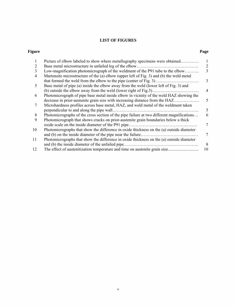
10 Photomicrographs that show the difference in oxide thickness on the (a) outside diameter and (b) on the inside diameter of the pipe near the failure………………………………..… 7 11 Photomicrographs that show the difference in oxide thickness on the (a) outside diameter and (b) the inside diameter of the unfailed pipe…………………………………………….. 8 12 The effect of austenitization temperature and time on austenite grain size............................. 10
v
ABSTRACT
A modified 9Cr-1Mo steel (P91) pipe failure in a feedwater line in a chemical plant was investigated. The failure occurred in the vicinity of an elbow produced with socket welds of the pipe to the elbow. Based on metallography and hardness measurements, it was concluded that failure occurred because of an improper post-weld heat treatment of the socket weldment.
vii
INTRODUCTION A modified 9Cr-1Mo feedwater (condensate) line at an Eastman Chemical Company plant failed in January 2005. The line was in continuous service since start-up December 2001 until failure. The Plant Superintendent estimated there were three thermal cycles since start-up, although there may have been as many as 25 thermal cycles during commissioning. Normal operating temperature was 325ºF (163ºC) and pressure was 1762 psig. The line was steam traced with the tracing activated only when ambient outdoor temperature dropped to 40°F (5ºC). Failure Description
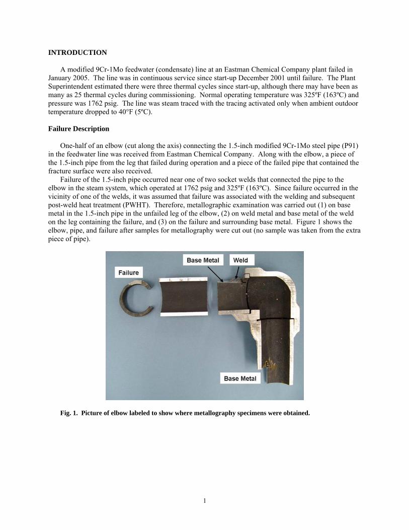
One-half of an elbow (cut along the axis) connecting the 1.5-inch modified 9Cr-1Mo steel pipe (P91) in the feedwater line was received from Eastman Chemical Company. Along with the elbow, a piece of the 1.5-inch pipe from the leg that failed during operation and a piece of the failed pipe that contained the fracture surface were also received. Failure of the 1.5-inch pipe occurred near one of two socket welds that connected the pipe to the elbow in the steam system, which operated at 1762 psig and 325ºF (163ºC). Since failure occurred in the vicinity of one of the welds, it was assumed that failure was associated with the welding and subsequent post-weld heat treatment (PWHT). Therefore, metallographic examination was carried out (1) on base metal in the 1.5-inch pipe in the unfailed leg of the elbow, (2) on weld metal and base metal of the weld on the leg containing the failure, and (3) on the failure and surrounding base metal. Figure 1 shows the elbow, pipe, and failure after samples for metallography were cut out (no sample was taken from the extra piece of pipe).
Fig. 1. Picture of elbow labeled to show where metallography specimens were obtained.
1
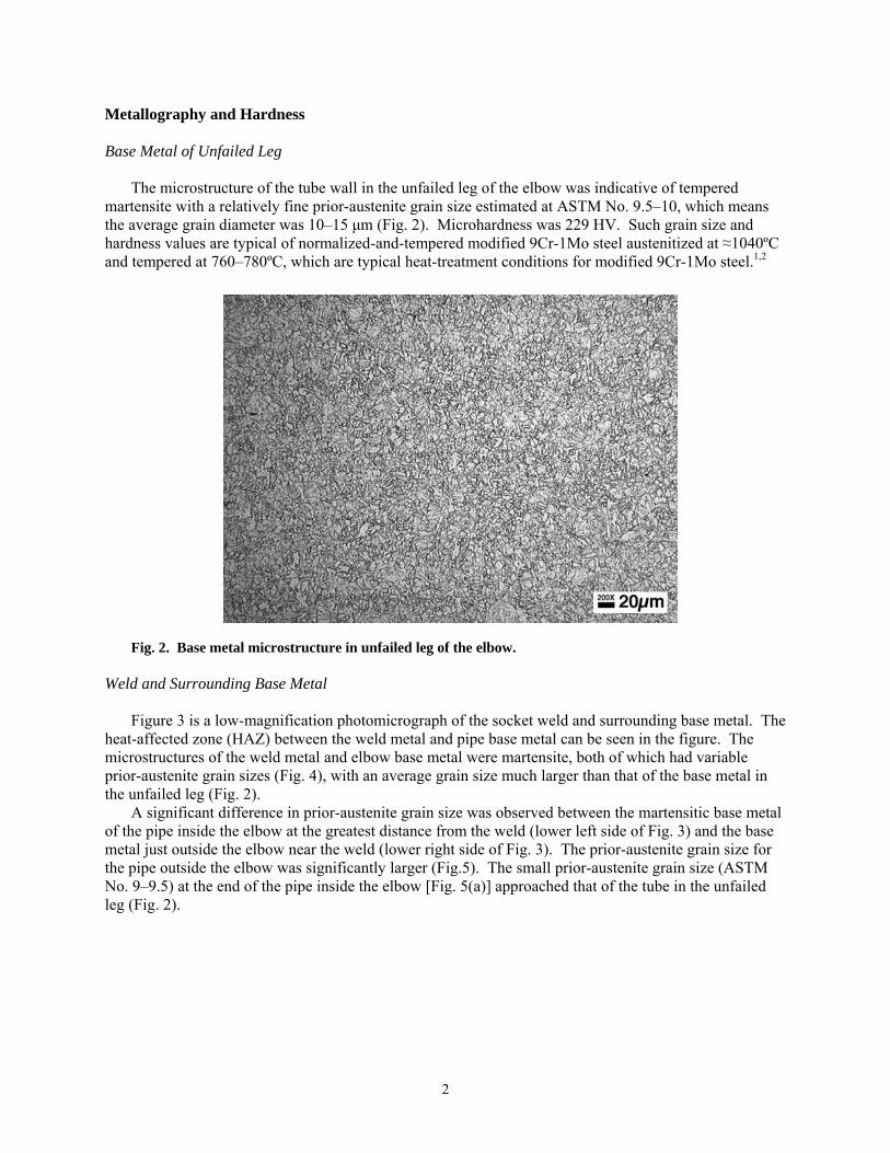
Metallography and Hardness Base Metal of Unfailed Leg The microstructure of the tube wall in the unfailed leg of the elbow was indicative of tempered martensite with a relatively fine prior-austenite grain size estimated at ASTM No. 9.5–10, which means the average grain diameter was 10–15 μm (Fig. 2). Microhardness was 229 HV. Such grain size and hardness values are typical of normalized-and-tempered modified 9Cr-1Mo steel austenitized at ≈1040ºC and tempered at 760–780ºC, which are typical heat-treatment conditions for modified 9Cr-1Mo steel.1,2
Fig. 2. Base metal microstructure in unfailed leg of the elbow.
Weld and Surrounding Base Metal Figure 3 is a low-magnification photomicrograph of the socket weld and surrounding base metal. The heat-affected zone (HAZ) between the weld metal and pipe base metal can be seen in the figure. The microstructures of the weld metal and elbow base metal were martensite, both of which had variable prior-austenite grain sizes (Fig. 4), with an average grain size much larger than that of the base metal in the unfailed leg (Fig. 2). A significant difference in prior-austenite grain size was observed between the martensitic base metal of the pipe inside the elbow at the greatest distance from the weld (lower left side of Fig. 3) and the base metal just outside the elbow near the weld (lower right side of Fig. 3). The prior-austenite grain size for the pipe outside the elbow was significantly larger (Fig.5). The small prior-austenite grain size (ASTM No. 9–9.5) at the end of the pipe inside the elbow [Fig. 5(a)] approached that of the tube in the unfailed leg (Fig. 2).
2
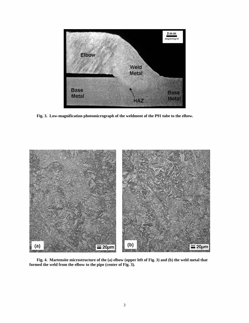
Fig. 3. Low-magnification photomicrograph of the weldment of the P91 tube to the elbow.
Fig. 4. Martensite microstructure of the (a) elbow (upper left of Fig. 3) and (b) the weld metal that
formed the weld from the elbow to the pipe (center of Fig. 3).
3
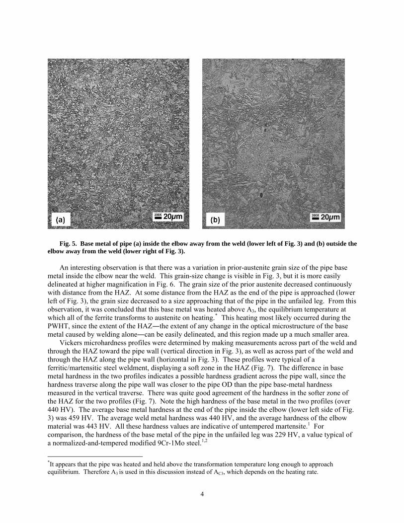
Fig. 5. Base metal of pipe (a) inside the elbow away from the weld (lower left of Fig. 3) and (b) outside the elbow away from the weld (lower right of Fig. 3). An interesting observation is that there was a variation in prior-austenite grain size of the pipe base metal inside the elbow near the weld. This grain-size change is visible in Fig. 3, but it is more easily delineated at higher magnification in Fig. 6. The grain size of the prior austenite decreased continuously with distance from the HAZ. At some distance from the HAZ as the end of the pipe is approached (lower left of Fig. 3), the grain size decreased to a size approaching that of the pipe in the unfailed leg. From this observation, it was concluded that this base metal was heated above A3, the equilibrium temperature at which all of the ferrite transforms to austenite on heating.* This heating most likely occurred during the PWHT, since the extent of the HAZ―the extent of any change in the optical microstructure of the base metal caused by welding alone―can be easily delineated, and this region made up a much smaller area. Vickers microhardness profiles were determined by making measurements across part of the weld and through the HAZ toward the pipe wall (vertical direction in Fig. 3), as well as across part of the weld and through the HAZ along the pipe wall (horizontal in Fig. 3). These profiles were typical of a ferritic/martensitic steel weldment, displaying a soft zone in the HAZ (Fig. 7). The difference in base metal hardness in the two profiles indicates a possible hardness gradient across the pipe wall, since the hardness traverse along the pipe wall was closer to the pipe OD than the pipe base-metal hardness measured in the vertical traverse. There was quite good agreement of the hardness in the softer zone of the HAZ for the two profiles (Fig. 7). Note the high hardness of the base metal in the two profiles (over 440 HV). The average base metal hardness at the end of the pipe inside the elbow (lower left side of Fig. 3) was 459 HV. The average weld metal hardness was 440 HV, and the average hardness of the elbow material was 443 HV. All these hardness values are indicative of untempered martensite.1 For comparison, the hardness of the base metal of the pipe in the unfailed leg was 229 HV, a value typical of a normalized-and-tempered modified 9Cr-1Mo steel.1,2
*It appears that the pipe was heated and held above the transformation temperature long enough to approach equilibrium. Therefore A3 is used in this discussion instead of AC3, which depends on the heating rate.
4
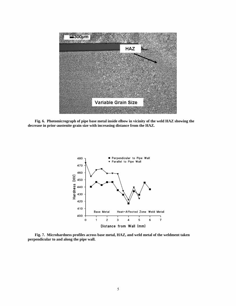
Fig. 6. Photomicrograph of pipe base metal inside elbow in vicinity of the weld HAZ showing the decrease in prior-austenite grain size with increasing distance from the HAZ.
Fig. 7. Microhardness profiles across base metal, HAZ, and weld metal of the weldment taken perpendicular to and along the pipe wall.
5
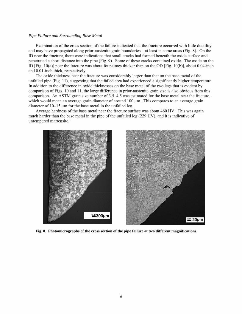
Pipe Failure and Surrounding Base Metal Examination of the cross section of the failure indicated that the fracture occurred with little ductility and may have propagated along prior-austenite grain boundaries―at least in some areas (Fig. 8). On the ID near the fracture, there were indications that small cracks had formed beneath the oxide surface and penetrated a short distance into the pipe (Fig. 9). Some of these cracks contained oxide. The oxide on the ID [Fig. 10(a)] near the fracture was about four-times thicker than on the OD [Fig. 10(b)], about 0.04-inch and 0.01-inch thick, respectively. The oxide thickness near the fracture was considerably larger than that on the base metal of the unfailed pipe (Fig. 11), suggesting that the failed area had experienced a significantly higher temperature. In addition to the difference in oxide thicknesses on the base metal of the two legs that is evident by comparison of Figs. 10 and 11, the large difference in prior-austenite grain size is also obvious from this comparison. An ASTM grain size number of 3.5–4.5 was estimated for the base metal near the fracture, which would mean an average grain diameter of around 100 μm. This compares to an average grain diameter of 10–15 μm for the base metal in the unfailed leg. Average hardness of the base metal near the fracture surface was about 460 HV. This was again much harder than the base metal in the pipe of the unfailed leg (229 HV), and it is indicative of untempered martensite.1
Fig. 8. Photomicrographs of the cross section of the pipe failure at two different magnifications.
6
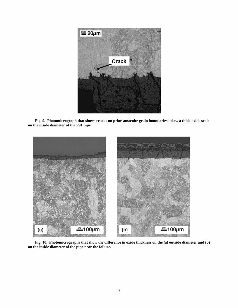
Fig. 9. Photomicrograph that shows cracks on prior-austenite grain boundaries below a thick oxide scale on the inside diameter of the P91 pipe.
Fig. 10. Photomicrographs that show the difference in oxide thickness on the (a) outside diameter and (b)
on the inside diameter of the pipe near the failure.
7
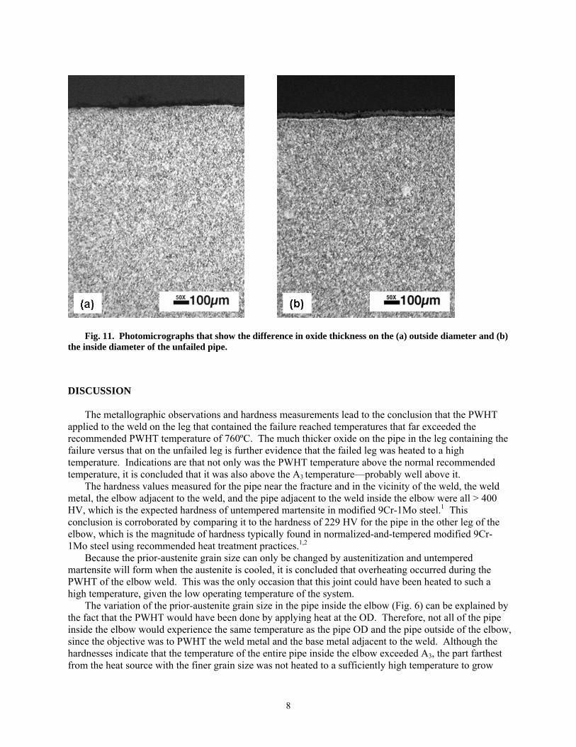
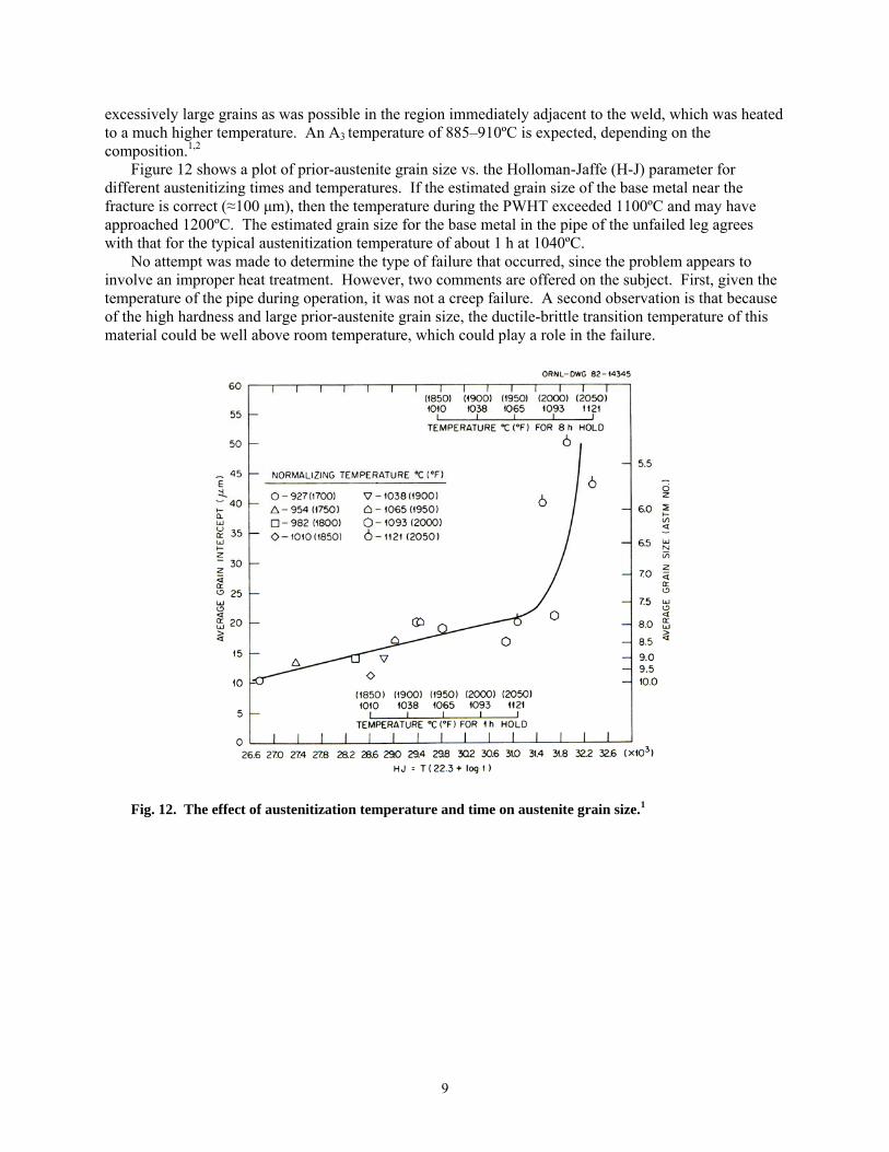
Fig. 11. Photomicrographs that show the difference in oxide thickness on the (a) outside diameter and (b) the inside diameter of the unfailed pipe. DISCUSSION The metallographic observations and hardness measurements lead to the conclusion that the PWHT applied to the weld on the leg that contained the failure reached temperatures that far exceeded the recommended PWHT temperature of 760ºC. The much thicker oxide on the pipe in the leg containing the failure versus that on the unfailed leg is further evidence that the failed leg was heated to a high temperature. Indications are that not only was the PWHT temperature above the normal recommended temperature, it is concluded that it was also above the A3 temperature—probably well above it. The hardness values measured for the pipe near the fracture and in the vicinity of the weld, the weld metal, the elbow adjacent to the weld, and the pipe adjacent to the weld inside the elbow were all > 400 HV, which is the expected hardness of untempered martensite in modified 9Cr-1Mo steel.1 This conclusion is corroborated by comparing it to the hardness of 229 HV for the pipe in the other leg of the elbow, which is the magnitude of hardness typically found in normalized-and-tempered modified 9Cr-1Mo steel using recommended heat treatment practices.1,2
Because the prior-austenite grain size can only be changed by austenitization and untempered martensite will form when the austenite is cooled, it is concluded that overheating occurred during the PWHT of the elbow weld. This was the only occasion that this joint could have been heated to such a high temperature, given the low operating temperature of the system. The variation of the prior-austenite grain size in the pipe inside the elbow (Fig. 6) can be explained by the fact that the PWHT would have been done by applying heat at the OD. Therefore, not all of the pipe inside the elbow would experience the same temperature as the pipe OD and the pipe outside of the elbow, since the objective was to PWHT the weld metal and the base metal adjacent to the weld. Although the hardnesses indicate that the temperature of the entire pipe inside the elbow exceeded A3, the part farthest from the heat source with the finer grain size was not heated to a sufficiently high temperature to grow
8
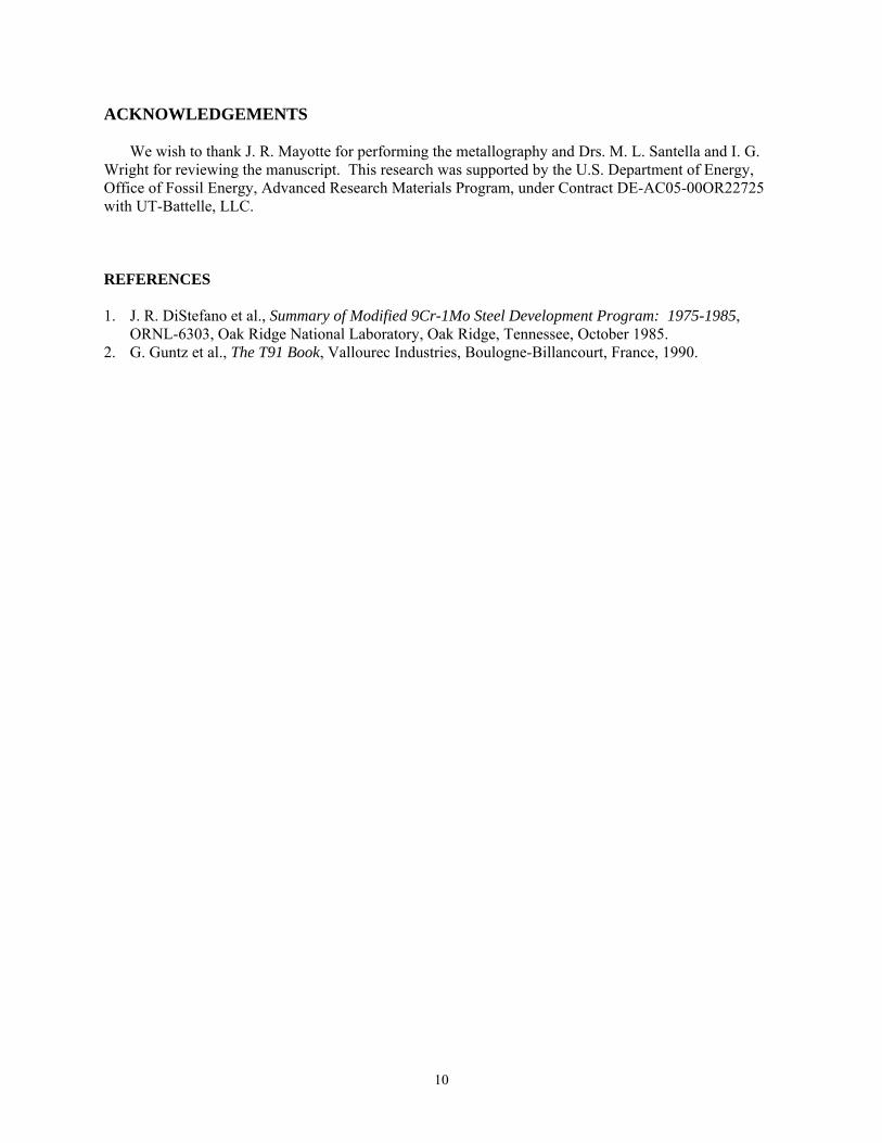
excessively large grains as was possible in the region immediately adjacent to the weld, which was heated to a much higher temperature. An A3 temperature of 885–910ºC is expected, depending on the composition.1,2 Figure 12 shows a plot of prior-austenite grain size vs. the Holloman-Jaffe (H-J) parameter for different austenitizing times and temperatures. If the estimated grain size of the base metal near the fracture is correct (≈100 μm), then the temperature during the PWHT exceeded 1100ºC and may have approached 1200ºC. The estimated grain size for the base metal in the pipe of the unfailed leg agrees with that for the typical austenitization temperature of about 1 h at 1040ºC. No attempt was made to determine the type of failure that occurred, since the problem appears to involve an improper heat treatment. However, two comments are offered on the subject. First, given the temperature of the pipe during operation, it was not a creep failure. A second observation is that because of the high hardness and large prior-austenite grain size, the ductile-brittle transition temperature of this material could be well above room temperature, which could play a role in the failure.
Fig. 12. The effect of austenitization temperature and time on austenite grain size.1
9
ACKNOWLEDGEMENTS We wish to thank J. R. Mayotte for performing the metallography and Drs. M. L. Santella and I. G. Wright for reviewing the manuscript. This research was supported by the U.S. Department of Energy, Office of Fossil Energy, Advanced Research Materials Program, under Contract DE-AC05-00OR22725 with UT-Battelle, LLC. REFERENCES 1. J. R. DiStefano et al., Summary of Modified 9Cr-1Mo Steel Development Program: 1975-1985,
ORNL-6303, Oak Ridge National Laboratory, Oak Ridge, Tennessee, October 1985. 2. G. Guntz et al., The T91 Book, Vallourec Industries, Boulogne-Billancourt, France, 1990.
10
ORNL/TM-2006/1
INTERNAL DISTRIBUTION
1. S. A. David 2. Z. Feng 3. R. R. Judkins 4. R. L. Klueh 5. E. Lara-Curzio 6. R. G. Miller
7. R. K. Nanstad 8. M. L. Santella 9. J. P. Shingledecker 10. R. E. Stoller 11. J. M. Vitek 12. I. G. Wright
EXTERNAL DISTRIBUTION
13. R. Sinko 14. R. W. Swindeman
11