interface for canbus engine - altervista
TRANSCRIPT

CAN 01
INTERFACE FOR CANBUS ENGINE

INDEX
1.0 GENERALITIES .................................................................................................................................... 3
1.0.1 ACRONYMS-ABBREVIATIONS ........................................................................................................ 3
1.1 AIM ........................................................................................................................................................ 3
1.2 FUNCTIONALITIES DESCRIPTION...................................................................................................... 3
1.3 OPERATIVE PANEL ............................................................................................................................. 4
1.3.0 DESCRIPTION OF THE CARD CONNECTIONS SIDE ......................................................................................... 4
1.4 FUNCTIONING ...................................................................................................................................... 5
1.4.0 COMBINING TO THE GCM02-C Rel.7.10 .............................................................................................................. 5
1.4.1 CANBUS ALARMS VISUALIZATION ................................................................................................................... 6
1.5 PUT IN SERVICE PROCEDURE ........................................................................................................... 8
1.5.0 ASSEMBLY ON GCM02-C ...................................................................................................................................... 8
1.5.1 SETTING ON GCM02-C REL 7.10 ........................................................................................................................... 9
1.5.2 FUNCTIONING ON GCM02-C REL 7.10 +IS03 or CS06 ....................................................................................... 9
1.5.3 ELECTRIC DIAGRAM ............................................................................................................................................. 9
1.5.3.1 CONNECTION TO THE VOLVO MOTOR ............................................................................................ 9
1.5.3.2 CONNECTION TO THE DEUTZ MOTOR ............................................................................................11
1.6 DAMAGES RESEARCH ..................................................................................................................... 12
1.7 TECHNICAL CHARACTERISTICS - FORCED STANDARDS ........................................................... 13
1.8 EQUIPMENT DISPOSAL AT THE END OF THE LIFE CYCLE ........................................................... 13
MANUAL OF:
INSTALLATION USE MAINTENANCE

USE MANUAL
1.0 GENERALITIES
CAN 01 is an electronic device that allows to the card GCM02-C (Release 7 or sup.) or MC3 (release 5 or sup.) to interface with CANBUS of different motors of the electron groups.
CANBUS is a modern and strong communication system suitable of every type of motors control.
From some time the industrial motors of a certain power are supplied of this system standardized from SAE with the standard SAE J1939 that defines speed, addresses, lengths and transmissions priority.
1.0.1 ACRONYMS-ABBREVIATIONS
1.1 AIM
In this manual are supplied all information necessary for: 1. To know all equipment functioning; 2. Install the electronic card in relation to the various functioning modalities; 3. Perform the minimum controls necessary to guarantee the equipment maximum performance
1.2 FUNCTIONALITIES DESCRIPTION
CAN 01 is an interface composed from microprocessor dedicated to the messages control and from a line CANBUS driver that performs physically the communication in the system.
The microprocessor is connected to the GCM02-C card through a SPI door that receives the controls processing the messages in exit to the motor. Vice versa it selects the important messages and supplies them to the card for the processing.
MC3 uses instead only the line driver, managing the messages directly on the CAN door that is placed on its internal.
In both cases CAN01 receives the feeding from the cards that accommodate it through the telephonic cable with 8 poles RJ12 that connect to it.
Acronym Description CAN Controller Area Network FMI Failure Mode Indicator (SAE J1939) OC Occurrence Count (SAE J1939) SPN Suspect Parameter Number (SAE J1939)

1.3 OPERATIVE PANEL
11..33..00 DDEESSCCRRIIPPTTIIOONN OOFF TTHHEE CCAARRDD CCOONNNNEECCTTIIOONNSS SSIIDDEE
1. Connection connector to the CANBUS. H = Can High, L = Can Low, SH = Shield (Screening) 2. Led TX CANBUS, shows the data transmission from the CAN01 to the CAN line. 3. Led RX CANBUS, shows the data reception on the CAN01 from the CAN line. 4. Configuration Switch. Allow to set CAN01 to function with GCM02C or MC3 5. Connection connector to the control card (GCM02C or MC3). 6. Led SI Serial Input, shows the data reception on the CAN01 from the serial SPI of the GCM02C. 7. Led So Serial Output shows the data transmission on the CAN01 from the serial SPI of the GCM02C.
SUPERIOR SIGHT
41 2 3 5 6 7

1.4 FUNCTIONING
11..44..00 CCOOMMBBIINNIINNGG TTOO TTHHEE GGCCMM0022--CC RReell..77..1100 Feeding GCM02-C contemporary the CAN 01 switches on. GCM02-C communicates with CAN01 and if it is able to finish the setting procedure, it signals with the page:
C A N 0 1 C O N N E C T E D
Pushing the reset button, this visualization is deleted entering in the measure pages. In the standard pages, some measures previously found from sensors directly connected to the GCM02-C are substituted from the values received through CANBUS. Come from the CANBUS: motor revolutions (RPM), oil pressure (PO), motor temperature (TM).
0 R P M
O P 0 . 0 B E T 0 °
On PO and TM the pre alarms remain active on the levels set in the GCM02C settings and the Hours meter.
H O U R - M E T E R
0 h 0 m 0 s
The hours meter has a particular functioning and receives from CANBUS a value in 1/20 of hours (3 minutes). So the maximum resolution is of 3 minutes and sometimes the card hours meter functioning sovrapposto at the value reception from CANBUS causes jumps of 3 minutes. The hours meter is however precise and aligned to the motor one. Except the measures included in the standard pages, other pages have been added that are visualized only if the value to show is received from the CANBUS. The pages are visible after the hours meter page (pushing - ) or before the net general page (pushing + ). They visualize in the order: 1- oil level and water level
O I L L E V . 1 0 0 %
W A T E R L E V . 1 0 0 %
The levels are indicated in percentage
2- Fuel consumption and instantaneous performance
F U E L R A T E 1 0 . 0 L / h
E F F I C I E N . 2 . 0 0 k Wh / L

The consumption is visualized in Liters per hour and the performance is calculated dividing the real power for the consumption. The result is a value in kilowatt-hour per liter. 3- Fuel temperature (FT), boost pressure (BP), intake manifold temperature (IMT) and atmospheric pressure (AP).
F T 4 0 ° C B P 3 . 6 B a r
I M T 5 0 ° C A P 1 1 0 0 mB
The temperatures are in degrees centigrade, the turbo pressure in Bar and the atmospheric pressure in Millbar. 4- Communication BUS status page
C A N 0 1 C O N N E C T E D
B U S J 1 9 3 9 O N R X
The inscription ON shows that the card is connected to an active CANBUS, the inscription RX shows the data reception from the BUS. 11..44..11 CCAANNBBUUSS AALLAARRMMSS VVIISSUUAALLIIZZAATTIIOONN
The CANBUS error codes are translated and visualized in the following way:
A L A R M
2 A C T I V E F A U L T / S
A M B E R L A M P
B O O S T P R E S S U R E
B E L O W N O R M A L 3 O C
O I L P R E S S U R E
S E N S O R / A C T . F A U L T 6 O C
1- Appear a generic page with the inscription “ALARM” 2- After 2” the page is changed from a page indicating the number of “ACTIVE FAULT/S” and the severity of
these alarms on 3 levels in order of seriousness (SAE j1939 – 73)
RED LAMP Heavy anomaly with immediate motor stop
AMBER LAMP Anomaly that doesn’t request the immediate stop
PROTECTION LAMP Anomaly for set limit exceeding (ex high temperature)
In case of multiple alarms, the heaviest level is indicated.

3- After other 2“ there is the alarm indication noticed with a page composed from: Problem indication through an inscription on the first row that translates the received SPN code in accordance with the following table.
Message SPNFUEL DELIVERY PRESS. 94WATER IN FUEL 97OIL LEVEL 98OIL PRESSURE 100BOOST PRESSURE 102INT.MANIFOLD TEMP. 105AIR FILTER DIF. PRESSURE 107COOLANT TEMPERATURE 110COOLANT LEVEL 111CRANKCASE PRESSURE 153BATTERY VOLTAGE 158FUEL TEMPERATURE 174OIL TEMPERATURE 175SPEED SENSOR 190PREHEATING ACTUATOR 626SENSOR SPEED 636SENSOR SPEED 637INJECTOR 1 651INJECTOR 2 652INJECTOR 3 653INJECTOR 4 654INJECTOR 5 655INJECTOR 6 656STARTING MOTOR 677PISTONS COOLING 520192
If the received SPN code isn’t showed in the previous table, it is visualized directly in numerical form. The second row gives information on the damage typology translating the FMI code in accordance with the following table.
ABOVE NORMAL 0BELOW NORMAL 1INCORRECT/INTERM. 2SENSOR /ACT.FAULT 3SENSOR /ACT.FAULT 4SENSOR /ACT.FAULT 5SENSOR /ACT.FAULT 6MECHANICAL FAULT 7
If the received FMI code isn’t showed in the previous table, it is visualized directly in numerical form. Always in the second row it is showed the times number that this alarm has been noticed followed from the OC acronym.
4- If other alarms are present (up to 4), every 2” a new descriptive page appears up to the events exhaustion,
after that the first page reappears showing the inscription “ALARM” and the program resumes to turn the pages up to the problem elimination or to the reset procedure execution.
In the visualized example, purely indicative, we have two alarms that don’t cause the generator stop. The first one shows a turbo pressure value (SPN 102) inferior to the foreseen limits (FMI 0), problem yet seen 3 times (3 OC). The second alarm shows a problem to the sensor (FMI 3-4-5-6) of oil pressure survey (SPN 100), problem yet seen 6 times (6 OC).

1.5 PUT IN SERVICE PROCEDURE
11..55..00 AASSSSEEMMBBLLYY OONN GGCCMM0022--CC
Place the CAN01 back the GCM02-C control module in the outlined space and fasten it to the chain guard using the apposite screws in equipment of the apparatus.
Insert the RJ45 connector in equipment in the proper socket on the CAN01 (SERIAL FOR GCM02C - MC3C) and the other plug in the socket on the GCM02-C ( CANBUS).
Prepare the Switches setting on the CAN01 in accordance with the showed configuration and connect the CANBUS line at the card entry.

For the connection of the CAN01 to the GCM02C, use the cable in equipment that is of the correct length. The connection between 2 cards happens through a high-speed serial door and so put the CAN01 a long way from GCM02C. Using a not standard cable, some communication problems can happen. The connection to the line CANBUS must be performed with twisted cables or, better still, with screened cables.
11..55..11 SSEETTTTIINNGG OONN GGCCMM0022--CC RREELL 77..1100
In this phase it is necessary to select the motor type connected to the CANBUS. To access to the settings, activate the switch SW nr 4 placing it on ON. In the section VARIOUS REGULATIONS, you will find the selection page of the connected motor type. 2 options are available: VOLVO EMS2 (functioning also with EDC3 and EDC4) and DEUTZ EMR2. Once the selection is performed, disconnect all system to allow a simultaneous switching on of the motor switchboard and of the GCM02-C CAN01. This simultaneous re feeding is important in the systems that use the motor switchboard always fed.
S E L E C . E N G I N E B U S
V O L V O E M S 2
11..55..22 FFUUNNCCTTIIOONNIINNGG OONN GGCCMM0022--CC RREELL 77..1100 ++IISS0033 oorr CCSS0066
The CAN01 can be used contemporary to the IS03. On the backside of the GCM02C the CAN01 will be assembled, while the IS03 will be assembled on the bottom of the electric panel, using the longest connection cable in equipment. The settings and functionalities relative to IS03 will remain the same. The use will be analogous in concomitance with CS06, RC01, and RC02. These will maintain unchanged their functionality.
11..55..33 EELLEECCTTRRIICC DDIIAAGGRRAAMM
1.5.3.1 CONNECTION TO THE VOLVO MOTOR
CAN01 can be connected to Tad 940, 941, 1242 and every motor equipped with EDC4, EDC 3 ,EMS2. Connecting to the CANBUS of these motors, apart from the cited measures, it is possible to manage the switching on and the motor stopping without the use of the relay controls.
Volvo motor diagram

The connection is performed on the “Contact Data Bus” (11).
Connection diagram Volvo GCM02C+CAN01. In the diagram the connections aren’t showed from the alternator side and from the commutation.

1.5.3.2 CONNECTION TO DEUTZ ENGINE
In the case of connection to engine Deutz, also the switching on and stopping controls will be wired. They are not managed from the CANBUS protocol. CAN01 can be connected to the motors DEUTZ with switching boards EMR2 or EMR3.
Deutz engine diagram
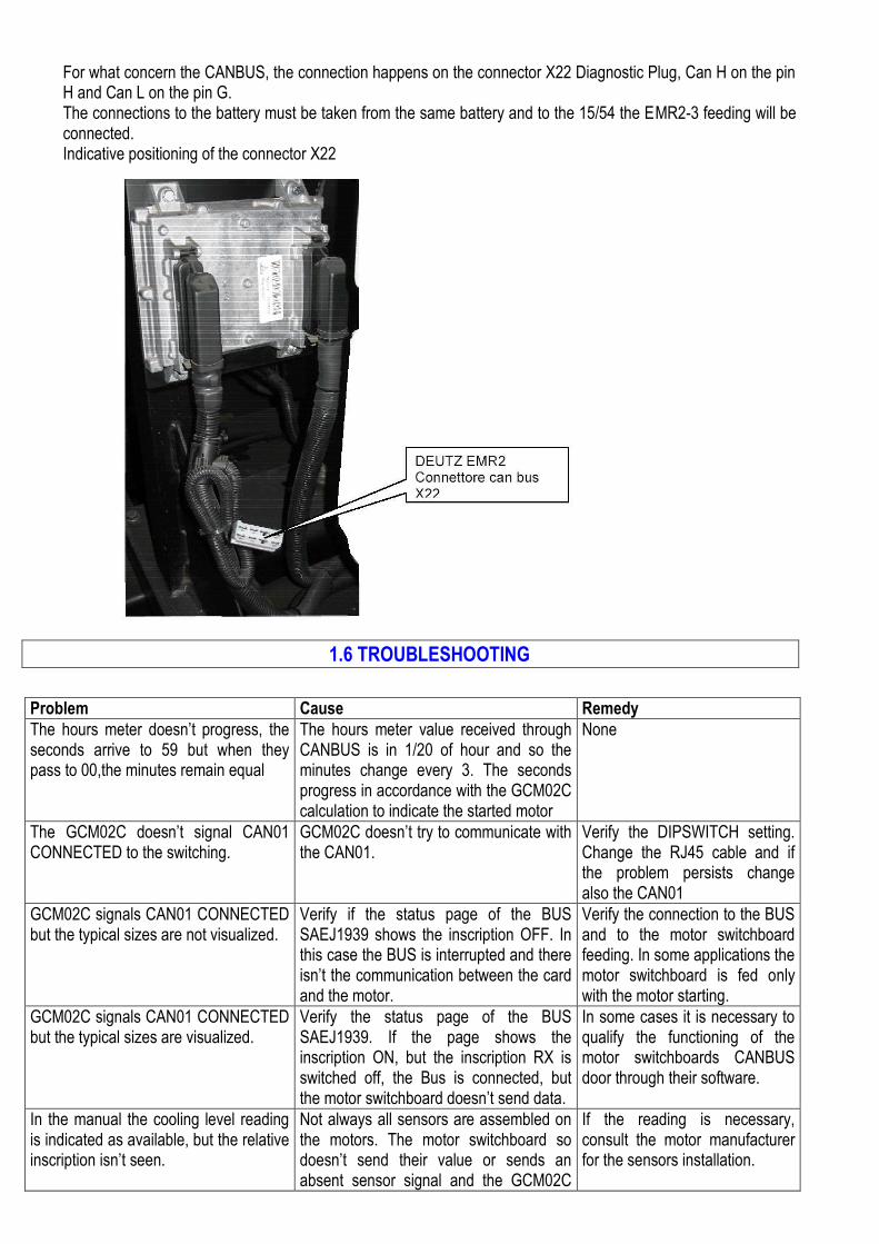
For what concern the CANBUS, the connection happens on the connector X22 Diagnostic Plug, Can H on the pin H and Can L on the pin G. The connections to the battery must be taken from the same battery and to the 15/54 the EMR2-3 feeding will be connected. Indicative positioning of the connector X22
1.6 TROUBLESHOOTING
Problem Cause Remedy
The hours meter doesn’t progress, the seconds arrive to 59 but when they pass to 00,the minutes remain equal
The hours meter value received through CANBUS is in 1/20 of hour and so the minutes change every 3. The seconds progress in accordance with the GCM02C calculation to indicate the started motor
None
The GCM02C doesn’t signal CAN01 CONNECTED to the switching.
GCM02C doesn’t try to communicate with the CAN01.
Verify the DIPSWITCH setting. Change the RJ45 cable and if the problem persists change also the CAN01
GCM02C signals CAN01 CONNECTED but the typical sizes are not visualized.
Verify if the status page of the BUS SAEJ1939 shows the inscription OFF. In this case the BUS is interrupted and there isn’t the communication between the card and the motor.
Verify the connection to the BUS and to the motor switchboard feeding. In some applications the motor switchboard is fed only with the motor starting.
GCM02C signals CAN01 CONNECTED but the typical sizes are visualized.
Verify the status page of the BUS SAEJ1939. If the page shows the inscription ON, but the inscription RX is switched off, the Bus is connected, but the motor switchboard doesn’t send data.
In some cases it is necessary to qualify the functioning of the motor switchboards CANBUS door through their software.
In the manual the cooling level reading is indicated as available, but the relative inscription isn’t seen.
Not always all sensors are assembled on the motors. The motor switchboard so doesn’t send their value or sends an absent sensor signal and the GCM02C
If the reading is necessary, consult the motor manufacturer for the sensors installation.

doesn’t visualize not even the relative inscriptions.
The connected Volvo motor sends the readings but it doesn’t try to start up
Verify the motor selection setting on the GCM02C. The starting string is not sent if the motor DEUTZ is selected.
Change the setting on GCM02C and select the Volvo motor.
The connected Volvo motor doesn’t send the readings, it is difficult to start up or continue to give alarms with SPN numbers not included in the table.
The switchboards of some motors have the necessity to be fed contemporary to the GCM02C or successively to this one. If during the first switching on seconds don’t receive signals on the door CANBUS, they render it practically unusable.
Disconnect all the plant and e re feed contemporarily GCM02C and EMSx.
1.7 TECHNICAL CHARACTERISTICS - FORCED STANDARDS
Characteristics Values Feeding 5V ± 3%
Rest current 10 mA
Connections Connector Phoenix for line CANBUS Plug RJ45 for connection to the GCM02-C
Functioning temperature - 20 - + 70 °C
Humidity + 80 % not condensed
Sizes L 150 H 40 D 65 mm
Weight 100 g
FORCED STANDARDS SAE J1939 – CEI EN 61000 – DIRECTIVE EMC 2004/108/CE
1.8 EQUIPMENT DISPOSAL AT THE END OF THE LIFE CYCLE
At the end of the life cycle, the equipment cannot be disposed as urban refuse, but it must be disposed in the appropriate collection places and in the Centers instituted from the town halls, in accordance with the actual standards.