canbus hardware setup. canbus canbus is a control system method that can be used instead of the...
TRANSCRIPT

CANBus Hardware Setup
CANBus
CANBus is a control system method that can be used instead of the conventional PWM system.
It uses RJ12 cable, which is similar to ethernet cable, to link Jaguars together.
Advantages
• Ethernet cables are more robust than PWM’s
• Less wire is required because the cable runs from one Jaguar to the next
• Jaguars can handle PID loops, freeing processing on the CRio
More Advantages
• Jaguars in CAN can have Potentiometers or Encoders wired directly to them.
• CAN Jaguars can control motors just like normal jaguars, but they can also control them according to position, voltage, speed, or RPM.
Disadvantages
• If one cable fails, the rest of the chain fails
• Only 20 ft. of cable may be used
• Only one Pot. or Encoder may be used per Jaguar
• Only 16 Jaguars (max.) may be used.
• RJ-12 Cable, Connectors, and Crimper
• At least one Black Jaguar
• Two 100 ohm resistors
• Modular Adapter: RJ-12 to DB9 Female
(Digikey Stock No. 046-0003-ND)
Things You’ll Need
Making the Adapter
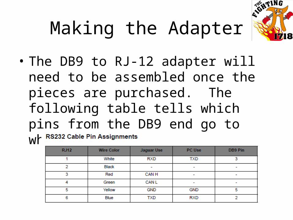
• The DB9 to RJ-12 adapter will need to be assembled once the pieces are purchased. The following table tells which pins from the DB9 end go to which wires on the RJ-12 end.
Placing the Adapter
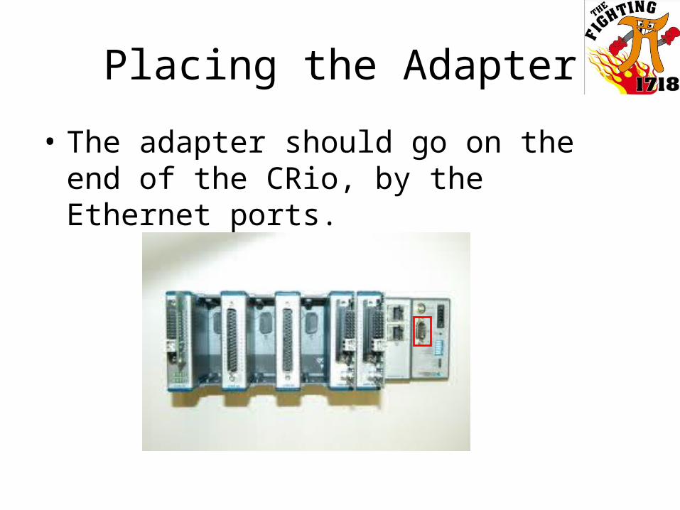
• The adapter should go on the end of the CRio, by the Ethernet ports.
Termination
Because CANbus is a bus system, it needs termination on either end of the network with a resistor. This means that on the cable connecting the adapter and the black Jaguar (or even inside the adapter), the Red and Green wires (wires 3 and 4) need to be bridged with one of the 100 ohm resistors. The second resistor will be used later.
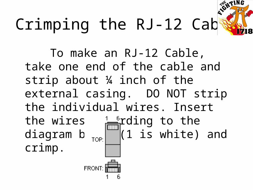
Crimping the RJ-12 Cable
To make an RJ-12 Cable, take one end of the cable and strip about ¼ inch of the external casing. DO NOT strip the individual wires. Insert the wires according to the diagram below (1 is white) and crimp.
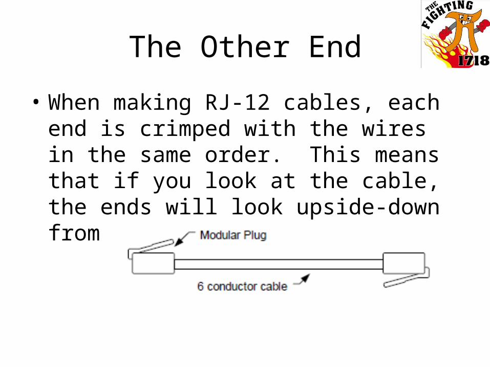
The Other End
• When making RJ-12 cables, each end is crimped with the wires in the same order. This means that if you look at the cable, the ends will look upside-down from each other.
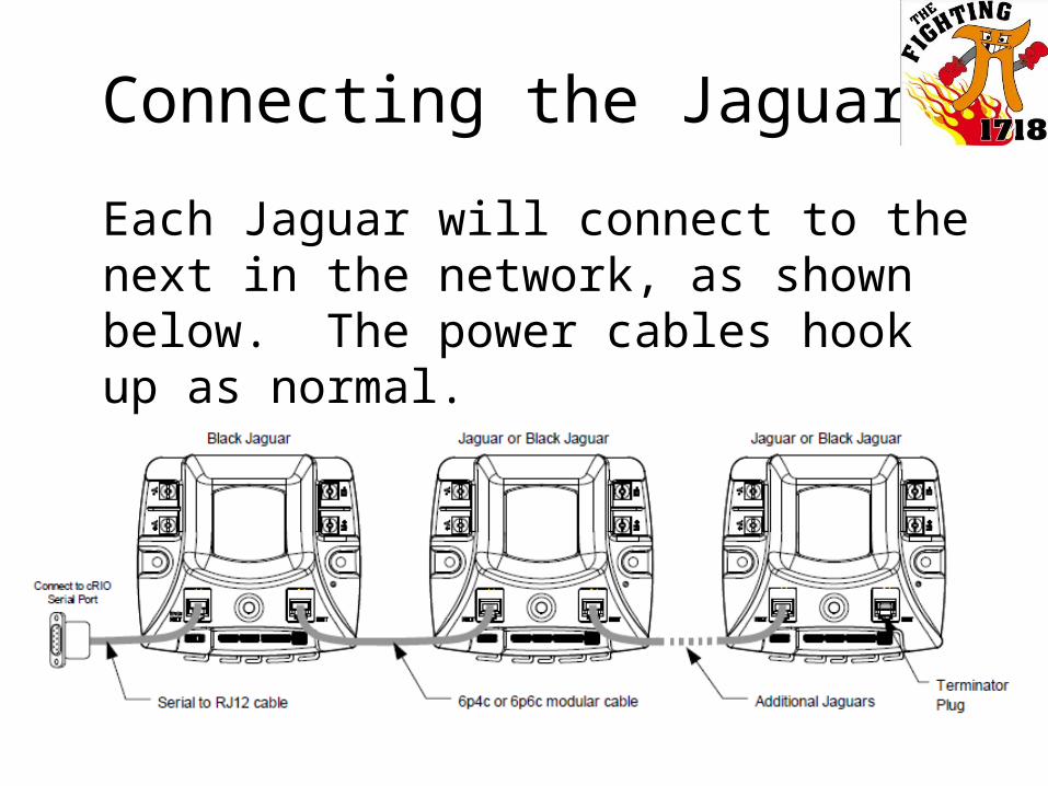
Connecting the Jaguars
Each Jaguar will connect to the next in the network, as shown below. The power cables hook up as normal.
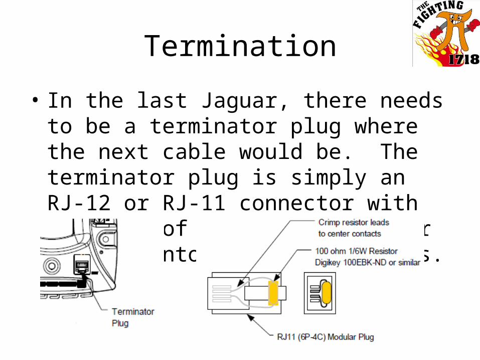
Termination
• In the last Jaguar, there needs to be a terminator plug where the next cable would be. The terminator plug is simply an RJ-12 or RJ-11 connector with the ends of a 100 ohm resistor crimped into the center 2 pins.
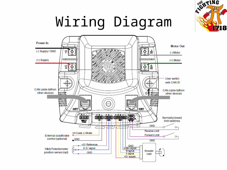
Wiring Diagram
All Diagrams were taken from the Jaguar User Manual

Questions?