installation and service guide - canon...
TRANSCRIPT
Canon ColorPASS-GX400
Installation and Service GuideA guide for service technicians
451112713 August 2012

© 2012 Electronics For Imaging
This documentation is protected by copyright, and all rights are reserved. No part of it may be reproduced or transmitted in any form or by any means for any purpose without express prior written consent from Electronics For Imaging (“EFI”), except as expressly permitted herein. Information in this documentation is subject to change without notice and does not represent a commitment on the part of EFI. The documentation is further covered by “Legal Notices” distributed with this product. The documentation may be provided in conjunction with EFI Software (“Software”) and any other EFI product described in the documentation. The Software is furnished under license and may only be used or copied in accordance with the terms of the Software License Agreement, which can be found in the “Legal Notices” distributed with this product.

CONTENTS 3
CONTENTS
PREFACE 9
ColorPASS customer media pack 9
About the documentation 10
Service documentation 10
Customer documentation 10
About this guide 11
About the illustrations in this guide 12
Terminology and conventions 12
Precautions 14
Creating an ESD safe environment 15
Tools you will need 18
INTRODUCTION 19
Features 19
How the ColorPASS operates 20
INSTALLATION 22
Installation sequence 22
Checking the customer site 24
Copier readiness 24
Setting customer expectations 25
Unpacking the ColorPASS 26
Connecting the ColorPASS 28
Completing installation and starting up 31
CONTENTS

CONTENTS 4
USING THE COLORPASS 32
Overview of the ColorPASS user interfaces 32
Using the ColorPASS Control Panel 32
Buttons 33
Activity light 33
ColorPASS Control Panel Functions menu 34
Using the copier touch panel 35
ColorPASS copier touch panel Functions menu 36
Print pages menu 39
Network Status LEDs 40
Starting, shutting down, restarting, and rebooting 41
SERVICE PROCEDURES 43
Overview 43
ColorPASS overview diagrams 44
Accessing internal components 48
Shutting down the system 48
Opening the ColorPASS 51
Removing and replacing boards 55
Copier interface board 55
User interface board assembly 57
Motherboard 60
Removing the motherboard 60
Replacing the motherboard 64
Verifying new motherboard installation and transferring options 69
Replacing parts on the motherboard 76
DIMMs 76
CPU 78
Battery 82
Clearing the CMOS 83
Jumpers 84

CONTENTS 5
Fan 85
Power supply 86
Hard disk drive 90
Switch bank assembly 96
DVD drive 100
Restoring and verifying functionality after service 103
SYSTEM AND USER SOFTWARE 104
Overview 104
Before you install system software 104
Backing up the system configuration 106
Restoring the system configuration 107
Installing system software 107
System software installation error messages 109
Installing software patches 110
System updates 110
TROUBLESHOOTING 111
Troubleshooting process 111
Preliminary on-site checkout 112
Checking external connections 113
Checking internal components 114
Inspecting the system 115
Normal startup sequence 120
Error messages and conditions 121

CONTENTS 6
SPECIFICATIONS 132
Hardware features 132
Physical specifications 132
Networking and connectivity 133
User software 133
Safety and emissions compliance 133
SERVICING THE COLORPASS WITH FURNITURE 134
Procedures 134
INDEX 145

LIST OF FIGURES 7
LIST OF FIGURES
FIGURE 1: Printing system 19
FIGURE 2: ColorPASS functional diagram 21
FIGURE 3: Summary of installation steps and references 23
FIGURE 4: ColorPASS shipping contents 27
FIGURE 5: ColorPASS connections 28
FIGURE 6: Straight-through and crossover Ethernet cables 29
FIGURE 7: ColorPASS Control Panel 32
FIGURE 8: Accessing the ColorPASS areas of the copier touch panel 35
FIGURE 9: Using the ColorPASS Functions menu from the copier touch panel 36
FIGURE 10: Front and back panels 44
FIGURE 11: Back panel and internal side view 45
FIGURE 12: Exploded view of ColorPASS components 46
FIGURE 13: Power and data cable connections in the ColorPASS 48
FIGURE 14: Removing/replacing the side panels 52
FIGURE 15: Removing/replacing the front panel 53
FIGURE 16: Removing/replacing the top panel 54
FIGURE 17: Diagram of the copier interface 55
FIGURE 18: Diagram of the user interface board (front and back) 57
FIGURE 19: Removing/replacing the user interface board 58
FIGURE 20: Removing/replacing the UIB buttons 59
FIGURE 21: Diagram of the ColorPASS motherboard 61
FIGURE 22: Removing the motherboard 63
LIST OF FIGURES
LIST OF FIGURES 8
LIST OF FIGURES
FIGURE 23: Connecting the dongle 70
FIGURE 24: Motherboard DIMM sockets 76
FIGURE 25: Releasing a DIMM 77
FIGURE 26: CPU cooling assembly 78
FIGURE 27: Removing/replacing the CPU 80
FIGURE 28: Motherboard battery 82
FIGURE 29: Removing the fan 85
FIGURE 30: Removing/replacing the power supply 88
FIGURE 31: ColorPASS hard disk drive 91
FIGURE 32: Removing/replacing the hard disk drive bracket 92
FIGURE 33: Removing/replacing the hard disk drive from/in the hard disk drive bracket 93
FIGURE 34: component sled with switch bank assembly 96
FIGURE 35: Removing/replacing the component sled from the chassis 97
FIGURE 36: Removing/replacing the switch bank assembly 98
FIGURE 37: ColorPASS DVD drive 100
FIGURE 38: Removing/replacing the DVD drive 101
FIGURE 39: Troubleshooting the system 111
FIGURE 40: ColorPASS external cable connections 113
FIGURE 41: Normal startup sequence 120
FIGURE 42: ColorPASS installed on the furniture 134

PREFACE 9
PREFACE
The Installation and Service Guide is intended for authorized Canon ColorPASS-GX400 and copier service technicians installing or servicing the Canon ColorPASS-GX400. If you are not an authorized service technician, do not attempt to install or service the Canon ColorPASS-GX400. Electronics for Imaging, Inc. does not warrant the performance of the Canon ColorPASS-GX400 if it is installed or serviced by non-authorized personnel.
NOTE: The term “ColorPASS” is used throughout this guide to refer to theCanon ColorPASS-GX400. The term “copier” is used to refer to the Canon imageRUNNER ADVANCE C9200/C7200 series and Canon imageRUNNER ADVANCE C5255.
ColorPASS customer media packThe ColorPASS customer media pack contains the following:
• System Software media
• User Software media (user documentation, Drivers and Utilities)
• Fiery Options Utility media
• ATM CD
• Canon Utility CDs and documentation
• End User License Agreement document
• Safety and Warnings document
• Secure Administrator Guide document
• Quick Setup
• Other documentation

PREFACE 10
About the documentationThe documentation for the ColorPASS is described in the following sections.
Service documentation
The scope of the Installation and Service Guide is limited to describing how to install ColorPASS hardware and system software and how to service and troubleshoot the ColorPASS. The Troubleshooting chapter focuses on the individual components of the ColorPASS hardware, as well as the ColorPASS connection to the network and copier.
Details about the copier, network, remote computers, software applications,and Microsoft Windows operating system software are beyond the scope of this guide.
For details about the content, terminology, and conventions of this guide, see the sections beginning on page 11.
Customer documentation
Customer documentation (also known as “user documentation”) is designed primarily for users and administrators. It also contains information that may be useful to service technicians; therefore, cross-references to the customer documentation are included in the Installation and Service Guide.
Service technicians can obtain user documentation from the User Documentation CD. Client users can obtain user documentation by using a Web browser to download documentation files from the ColorPASS. The documents are provided as Adobe Acrobat PDF (Portable Document Format) files, which are indexed and cross-referenced. In addition, some ColorPASS utilities (such as Command WorkStation) offer built-in Help.
For a complete description of the ColorPASS user documentation, see Welcome, which is part of the user documentation set.

PREFACE 11
About this guideThe Installation and Service Guide is organized into the following topics:
• Preface
General information, including a list of precautions.
• Introduction
General description of the ColorPASS.
• Installation
Checking the customer site and unpacking the ColorPASS; installing and connecting the ColorPASS.
• Using the ColorPASS
Overview of the ColorPASS functions and user interfaces; printing system pages; shutting down and restarting the ColorPASS.
• Service Procedures
Removal and replacement procedures for ColorPASS components; restoring and verifying functionality.
• System and user software
Overview of the system software; installing system and user software.
• Troubleshooting
Common problems and ways of correcting them; startup error messages; general system error conditions.
• Specifications
ColorPASS specifications.
• Servicing the ColorPASS with furniture (FACI option)
Assembly and disassembly instructions for systems mounted on the optional furniture with the optional monitor attached.
NOTE: The ColorPASS Installation and Service Guide is not intended for customer use. Do not leave the Installation and Service Guide at the customer site after servicing the ColorPASS.
PREFACE 12
About the illustrations in this guide
Illustrations reflect the current shipping version of the ColorPASS at the time of publication. Components shown in these illustrations are subject to change. To receive information about any ColorPASS components that do not match the illustrations in this guide, contact your authorized service/support center.
Terminology and conventions
The following sections explain the terminology and conventions used throughout this guide.
Service technician
In this guide, responsibilities attributed to the service technician may include the following:
• Making sure that the customer site has an appropriate electrical outlet and sufficient physical space for the ColorPASS
• Unpacking the ColorPASS
• Installing and connecting the ColorPASS
• Servicing the ColorPASS components
• Installing system and user software on the ColorPASS
Network administrator
In this guide, responsibilities attributed to the network administrator include the following:
• Verifying that the customer site is network-ready
• Configuring ColorPASS Network Setup options
• Configuring the connection between the ColorPASS and the Command WorkStation application installed on the ColorPASS
• Installing the user software shipped with the ColorPASS onto the networked Windows and Apple Mac OS computers that will print to it
• Configuring the connection between each remote computer and the ColorPASS

PREFACE 13
ColorPASS components
The terms “replace” and “replacing” are used throughout this guide to mean the reinstallation of existing components. Install new components only when necessary.
The term “Control Panel” refers to the area on the front of the ColorPASS, including the green/red activity light, the display window (LCD—liquid crystal display), and the buttons to the left and right of the display window.
The term “LCD” refers to the display window of the ColorPASS Control Panel.
The term “monitor” refers to the ColorPASS optional flat panel monitor.
The term “DVD drive” (Digital Versatile Disk drive) refers to the ColorPASS DVD drive.
The term “system software” refers to the following software installed on the ColorPASS hard disk drive (HDD):
• DVD 1: Fiery system software
• DVD 2 and DVD 3: Microsoft Windows 7 Professional for Embedded Systems x64 operating system software (Backup/Recovery and Upgrade)
• DVD 4: User Software
For other terms used to identify components of the ColorPASS, see the reference key in Figure 12 on page 46.
Connectors and components labeled “not used”
Connectors and components labeled “not used” are disabled or are not used in the standard ColorPASS configuration.
Document conventions
References to ColorPASS user documentation, such as Configuration and Setup, are displayed in italics. The user documentation files are installed from the user documentation set.
NOTE: The note format highlights important messages and additional information.
The warning icon indicates a potentially hazardous situation which, if instructions are not followed, could result in death or serious injury.
The caution icon indicates a potentially hazardous situation which, if instructions are not followed, may result in minor or moderate injury or damage to equipment.

PREFACE 14
PrecautionsAlways observe the following general precautions when installing and servicing the ColorPASS:
• Avoid pressing the surface of the LCD.
Applying excessive pressure to the LCD window will cause it to change color.
• Use a soft cloth moistened with Lens and Mirror Cleaner to clean the surface of the ColorPASS display window.
Other solvents, such as water, may damage the polarizer on the display window.
Never lift the ColorPASS by grasping the top panel. The top panel does not support the weight of the system.
ATTENTION: Ne jamais soulever le serveur d’impression par sa partie supérieure : celle-ci ne peut pas supporter le poids du système.
AVVERTENZA: Il server di stampa non deve essere mai sollevato afferrandolo dal pannello superiore, in quanto quest’ultimo non può sostenere il peso dell’intero sistema.
WARNUNG: Heben Sie den Druckserver nicht an der oberen Gehäuseabdeckung an. Die obere Gehäuseabdeckung ist nicht dafür ausgelegt, das Gesamtgewicht des Systems zu tragen.
DVERTENCIA: No levante nunca el servidor de impresión agarrándolo por el panel superior. El panel superior no soporta el peso del sistema.
ADVERTÊNCIA: Nunca erga o servidor de impressão pelo painel superior. O painel superior não suporta o peso do sistema.
WAARSCHUWING: Til de afdrukserver nooit op door het bovenpaneel vast te nemen. Het bovenpaneel kan het gewicht van het systeem niet dragen.
• When connecting or disconnecting the power cord:
– Only use the power cord that shipped with the ColorPASS or an appropriate replacement power cord available from an authorized provider.
– Always disconnect the power cord from the ColorPASS back panel before opening the unit and servicing internal components.
– Do not pull on the power cord when unplugging the ColorPASS. Pull the plug instead.
– Do not place objects on the power cord. Place the power cord away from foot traffic.
– Do not tamper with or disable the power cord grounding plug.
– Do not use a 3-prong adapter in a 2-hole ungrounded outlet.
– Do not use an extension cord.
– Do not plug the ColorPASS into a circuit with heating or refrigeration equipment (including water dispensers).
– Do not plug the ColorPASS into a switchable power outlet. This can result in the ColorPASS being turned off accidentally.
PREFACE 15
• Never set any liquid on or near the ColorPASS or copier. If liquid is spilled into the ColorPASS or copier, disconnect the power cord immediately.
• Do not attempt to open the power supply, DVD drive, or hard disk drive (HDD).
• Handle the ColorPASS LCD window with care.
If the ColorPASS LCD window breaks and the liquid crystal inside leaks out, avoid contact with it. If you come in contact with the liquid crystal, wash it off your skin immediately with soap and water.
• Use care when handling parts of the ColorPASS, as some edges on the unit may be sharp.
• Do not install third-party applications onto the ColorPASS. Third-party applications are not supported and can cause system problems. Although virus scans are permitted on the ColorPASS, virus-protection software should not be loaded in memory-resident mode.
• Do not change the Windows operating system software preference settings.
Depending on the changes made, the ColorPASS may become unstable or even unusable. If this occurs, we recommend that you reinstall the ColorPASS System Software, which reliably restores the Windows operating system software to its factory defaults.
• Never alter an existing network without permission.
The ColorPASS will probably be connected to an existing Local Area Network (LAN) based on Ethernet hardware. The network is the link between the customer’s computer, existing laser printers, and other prepress equipment. Never disturb the LAN by breaking or making a network connection, altering termination, installing or removing networking hardware or software, or shutting down networked devices without the knowledge and explicit permission of the system or network administrator or the shop supervisor.
• Unless you are the network administrator, never assign an IP address in ColorPASS Network Setup.
In a DHCP environment, the system assigns the IP address automatically. In a non-DHCP environment, you should enter only the IP address that has been assigned by the network administrator. Only the network administrator should assign an IP address to a network device. Assigning the ColorPASS an incorrect IP address may cause unpredictable errors on any or all devices connected to the network.
Creating an ESD safe environment• Follow standard ESD (electrostatic discharge) precautions while working on the internal
components of the ColorPASS.
Static is always a concern when servicing electronic devices. It is highly unlikely that the area around the copier and the ColorPASS is static-free. Carpeting, leather-soled shoes, synthetic clothing fibers, silks, and plastics may generate a static charge of more than 10,000 volts. Static discharge is capable of destroying the circuits etched in silicon microchips, or dramatically shortening their life span. By observing standard precautions, you may avoid extra service calls and save the cost of a new board.

PREFACE 16
When possible, work on a ground-connected antistatic mat. Wear an antistatic grounding strap, grounded at the same place as the antistatic mat. If that is not possible, do the following:
• Attach a grounding strap to your wrist. Attach the other end to a good ground.
• When you unpack the ColorPASS from the carton for the first time, touch a metal area of the copier to discharge the static on your body.
• Before you remove any of the ColorPASS panels and handle internal components, touch a metal part of the ColorPASS.
• Leave new electronic components inside their antistatic bags until you are ready to install them. When you remove components from an antistatic bag, place them on a grounded antistatic surface, component-side up.
• When you remove an electronic component, place it in an antistatic bag immediately. Do not walk across a carpet or vinyl floor while carrying an unprotected board.
• During service to the motherboard, avoid using excessive force and always place the motherboard on a grounded, non-metallic, static-free surface. Never allow any metal to touch the solder contacts on the underside of the motherboard, especially beneath the battery socket. Improper handling can short-circuit and permanently damage the motherboard.
• Handle printed circuit boards by their opposing edges only and avoid touching the contacts on the edge of the board.
Power Supply Cord Notice
The power supply cord is used as the main disconnect device. Ensure that the socket-outlet is located/installed near the equipment and is easily accessible.
ATTENTION: Le cordon d’alimentation doit être débranché pour une mise hors tension totale du produit. La prise de courant doit être située ou installée à proximité du matériel et être facilement accessible.
ATTENZIONE: Il cavo di alimentazione deve essere scollegato per interrompere completamente la corrente. Accertarsi che la presa di corrente si trovi o sia installata vicino alla macchina e sia facilmente accessibile.
ACHTUNG: Der Netzstecker dient zur sicheren Trennung des Gerätes von der Stromversorgung. Stellen Sie sicher, dass sich die Steckdose in unmittelbarer Nähe des Gerätes befindet und leicht zugänglich ist.
CUIDADO: El cable de alimentación eléctrica se utiliza como dispositivo de desconexión principal. Asegúrese de que el enchufe-toma esté situado/instalado cerca del equipo y que sea fácilmente accesible.
CUIDADO: O cabo de força é usado como dispositivo principal de desconexão. Assegure-se de que a saída de energia esteja localizada/instalada próxima ao equipamento e facilmente acessível.
VOORZICHTIG: Het netsnoer moet worden uitgetrokken om de stroomvoorziening te onderbreken. Zorg ervoor dat het stopcontact zich dicht bij het apparaat bevindt en gemakkelijk toegankelijk is.

PREFACE 17
Lithium Battery Notice
There is a danger of explosion if the battery is replaced with an incorrect type. Replace a battery only with the same type recommended by the manufacturer. Dispose of used batteries according to local regulations.
ACHTUNG: Es besteht Explosionsgefahr, wenn die Batterie durch eine Batterie falschen Typs ersetzt wird. Als Ersatz dürfen nur vom Hersteller empfohlene Batterien gleichen oder ähnlichen Typs verwendet werden. Verbrauchte Batterien müssen entsprechend den jeweiligen gesetzlichen Bestimmungen entsorgt werden.
ATTENTION: Il y a risque d’explosion si la pile est remplacée par un modèle qui ne convient pas. Remplacez-la uniquement par le modèle recommandé par le constructeur. Débarrassez-vous des piles usées conformément aux réglementations locales en vigueur.
ADVARSEL!: Litiumbatteri - Eksplosionsfare ved fejlagtig håndtering. Batteriet må kun udskiftes med et andet batteri af samme fabrikat og type. Brugte batterier skal bortskaffes i henhold til gældende regler.
VAROITUS: Paristo voi räjähtää, jos se on vaihdetaan väärän tyyppiseen paristoon. Vaihda paristo ainoastaan laitevalmistajan suosittelemaan tyyppiin. Hävitä käytetty paristo paikallisten määräysten mukaisesti.
ADVARSEL: Eksplosjonsfare ved feilaktig skifte av batteri. Benytt samme batteritype eller en tilsvarende type anbefalt av apparatfabrikanten. Brukte batterier kasseres i henhold til lokal lovgivning.
VARNING: Risk för explosion om batteriet byts ut mot en felaktig batterityp! Byt bara ut batteriet mot en batterityp som har godkänts av tillverkaren. Hantera använda batterier enligt lokal miljölagstiftning.
CUIDADO: Existe peligro de explosión si la batería se sustituye por una batería del tipo incorrecto. Sustituya la batería sólo por una batería del mismo tipo que recomienda el fabricante. Deseche las baterías usadas respetando la normativa local.
ATTENZIONE: Esiste pericolo di esplosione se la batteria viene sostituita con una di tipo non corretto. Sostituirla solamente con un tipo raccomandato dal produttore. Lo smaltimento delle batterie usate deve essere eseguito secondo le normative locali.
AVISO: Existe o perigo de explosão se a bateria for substituída por uma do tipo incorreto. Substitua somente por uma do tipo recomendado pelo fabricante. Descarte as baterias conforme as normas locais.
GEVAAR: Er bestaat ontploffingsgevaar indien de batterij door een verkeerd type wordt vervangen. Vervang de batterij uitsluitend door hetzelfde door de fabrikant aanbevolen type. Ruim gebruikte batterijen op volgens de plaatselijke voorschriften.

PREFACE 18
Short Circuit Protection
This product relies on the building’s installation for short-circuit (overcurrent) protection. Ensure that a fuse or circuit breaker no larger than 120 VAC, 15A U.S. (240 VAC, 10A international) is used on the phase conductors (all current-carrying conductors).
ATTENTION : La protection contre les courts-circuits (surtension) du produit est assurée par l’installation électrique du local où il est installé. S’assurer qu’un fusible ou un disjoncteur inférieur ou égal à 120 V CA , 15 A aux Etats-Unis (240 V CA, 10 A dans les autres pays) est utilisé pour les conducteurs de phase (conducteurs de courant).
AVVERTENZA: La protezione contro i short-circuit (sovracorrente) del prodotto dipende dall’impianto elettrico dell’edificio in cui è installato. Accertarsi che sui conduttori di fase (che portano la corrente) venga utilizzato un fusibile o interruttore non superiore a 120 Vc.a., 15 A negli Stati Uniti (240 Vc.a., 10 A internazzionale).
WARNUNG: Dieses Produkt ist darauf angewiesen, dass im Gebäude ein Kurzschluss- bzw. Überstromschutz installiert ist. Stellen Sie sicher, dass eine Sicherung oder ein Unterbrecher von nicht mehr als 240 V Wechselstrom, 10 A (bzw. in den USA 120 V Wechselstrom, 15 A) an den Phasenleitern (allen stromführenden Leitern) verwendet wird.
DVERTENCIA: Este producto depende de la instalación del edificio en lo relativo a la protección frente a cortocircuitos (sobretensión). Asegúrese de utilizar un fusible o un interruptor de circuito que no sea de más de 120 V CA, 15A en EE.UU. (240 V CA, 10A internacional) en los conductores de fase (todos los conductores que transportan corriente).
ADVERTÊNCIA: Esse produto depende da instalação de proteção contra curto-circuito (sobrecarga) do edifício. Assegure-se de que um fusível ou disjuntor de até 120 VAC, 15A U.S. (240 VAC, 10 A internacional) seja usado nos condutores de fase (todos os condutores de corrente).
WAARSCHUWING: Dit apparaat wordt tegen kortsluiting (overstroom) beveiligd via de elektrische installatie van het gebouw. Zorg ervoor dat de fasegeleiders (alle stroomvoerende geleiders) beveiligd zijn met een zekering of stroomonderbreker met een maximale capaciteit van 120 V wisselstroom, 15 A in de V.S. (240 V wisselstroom, 10 A internationaal).
Tools you will needTo install or service the ColorPASS, you will need the following tools and parts:
• ESD wrist grounding strap and antistatic mat
• Flathead screwdriver
• #0, #1, and #2 Phillips head screwdrivers
• Needlenose pliers
• ColorPASS documentation, including the customer media pack and any related service bulletins
Avoid touching magnetic tools to storage media such as hard disk drives. Contact between magnetic tools and magnetic storage media may result in data corruption.

INTRODUCTION 19
INTRODUCTION
The ColorPASS adds computer connectivity and highly efficient Adobe PostScript 3 color printing capability to the copier. It is optimized for high-speed network communications, processing, rasterization, and printing of continuous tone color and monochrome pages.
FeaturesThe ColorPASS, as an integral part of a color printing system, enables users to:
• Send images over AppleTalk and TCP/IP networks to ColorPASS supported devices.
• Spool print jobs and select a printing priority for each job. Users can control spooled print jobs sent to the ColorPASS with remote user software running on networked Windows and Mac OS computers.
• Print color, grayscale, and black-and-white jobs.
• Use the copier as a high-resolution color scanner with Fiery Scan software.
• Use 136 resident fonts (126 Adobe Type 1 PostScript and 10 TrueType), plus two Adobe Multiple Master fonts used for font substitution when printing PDF files. Command WorkStation or any third-party LaserWriter downloader, such as the Adobe Font Downloader, can be used to download additional fonts.
• Use built-in ColorWise color management and NetWise network features.
The ColorPASS also supports the Microsoft version of Internet Printing Protocol (IPP) for Windows 2000, Windows XP, Windows Server 2003, Windows Vista, Windows 7, and e-mail printing.
FIGURE 1: Printing system
The ColorPASS is one of several imaging products engineered and manufactured by Electronics for Imaging.
ColorPASS
Copier
Networked computers or workstations

INTRODUCTION 20
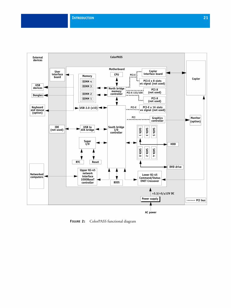
How the ColorPASS operatesThe ColorPASS enables the customer to use the copier as a high-performance, networked PostScript color printer and scanner. Users at the customer site can print to the ColorPASS from networked Windows computers, Mac OS computers, and networked UNIX workstations running TCP/IP.
The ColorPASS custom-designed boards and system software provide efficient image processing and printing controls.
The motherboard includes an Intel Core i5-660 3.3GHz CPU that controls the image data transfer to and from the motherboard and runs the interpreter. The interpreter rasterizes the page description file and compresses the image pattern into memory using compression technology.
High-speed DIMMs (dual in-line memory modules) on the motherboard hold the image data during printing. The ColorPASS is configured with two 1GB DIMMs, for a total of 2GB of memory.
When Fiery Scan uses the copier as a scanner, the ColorPASS acquires RGB (red, green, and blue) image data from the copier, stores it in memory, and transmits it to the computer that requested the scan.
INTRODUCTION 21
FIGURE 2: ColorPASS functional diagram
Motherboard
Power supply
Externaldevices
+3.3/+5/±12V DC
AC power
Copier
USB 2.0 (x10)
RTC
IDE(not used)
SuperI/O
Memory
USB toATA bridge
CPU
BIOS
Networkedcomputers
South bridgeI/O
controller
PCI bus
Upper RJ-45networkinterface
1000BaseTcontroller
Lower RJ-45Command/StatusENET Crossover
Userinterface
board
PCI-EKeyboardand mouse(option)
Monitor(option)
PCI-X 133/100SATA 0
USBdevices
Dongles
ColorPASS
DIMM 4
PCI
North bridgememory
controller
Copierinterface boardPCI-E
DIMM 3
DIMM 2
DIMM 1
Reset
PCI-X(not used)
PCI-E x 16 slotsx4 signal (not used)
DVD drive
HDD
SATA 2
SATA 4
SATA 1
SATA 3
SATA 5PCI-E x 8 slots
x4 signal (not used)
PCI-X(not used)
Graphicscontroller

INSTALLATION 22
INSTALLATION
This chapter includes information about the following:
• Installation sequence (see the following section)
• Checking the customer site (see page 24)
• Unpacking the ColorPASS (see page 26)
• Installing the ColorPASS and connecting it to the copier and the network (see page 28)
• Completing the installation (see page 31)
– Print a Test Page and a Configuration page.
– Remind the site administrator to install the current user software on networked computers that print to the ColorPASS (see Printing and Utilities, which is part of the user documentation set.
Installation sequenceFamiliarize yourself with this chapter before you attempt an installation. The installation sequence described in this chapter is designed to make your job as easy as possible. Installation problems are easier to avoid and diagnose if you proceed from the component to the system level and verify functionality at each stage. Figure 3 on page 23 outlines the recommended installation procedure for connecting the ColorPASS to the copier.
Because the ColorPASS is a node on the customer’s computer network, make sure that you coordinate your scheduled installation with the network administrator at the customer site. For Network Setup information, refer the network administrator to Configuration and Setup, which is part of the user documentation set.
NOTE: You can change the default language that is preinstalled at the factory using the Configure tool available through Command WorkStation and WebTools. Start Configure, choose Server > General > Choose Server Language, and then click Apply. It takes up to three minutes to change languages.
INSTALLATION 23
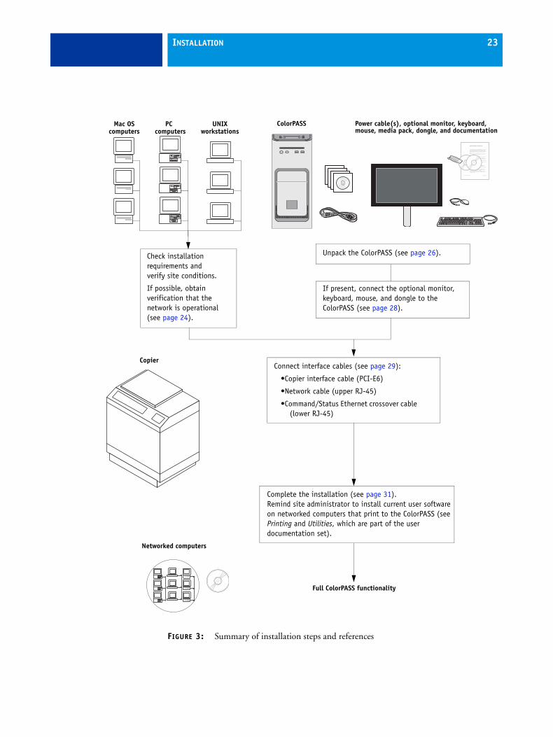
FIGURE 3: Summary of installation steps and references
Installing and Enabling Fiery SeeQuence Suite
Part Number: 4508991814 January 2010
Copyright 2010 © Electronics for Imaging, Inc.
This document describes how to install and enable Fiery SeeQuence Suite software, consisting of Fiery SeeQuence Impose and Fiery SeeQuence Compose, dongle-protected optional upgrade kits for Command WorkStation that work in conjunction with Adobe Acrobat and the Enfocus PitStop plug-in. You must install a kit-specific dongle on each client workstation that runs Fiery SeeQuence. This document explains how to install the dongle and the software.
NOTE: The terms “SeeQuence Impose” and “SeeQuence Compose” are used in this document to refer to Fiery SeeQuence Impose and Fiery SeeQuence Compose, respectively.
About SeeQuence Suite softwareFiery SeeQuence Suite software comprises integrated job preparation tools that allow you to do the following:
• SeeQuence Impose applies imposition layouts to jobs for custom printing, binding, and trimming. It also applies impositions to variable data jobs and saves imposed jobs as PDF files.
• SeeQuence Compose allows you to define the chapter divisions of a job, print ranges of pages on varying types of media, insert blank media between pages, and insert tab media containing text labels (if the copier supports tab printing).
• Preview provides a pre-RIP job preview and allows you to integrate SeeQuence Impose and SeeQuence Compose features in the same workflow.
About SeeQuence Suite kitsFiery SeeQuence Suite is available in the following optional kit configurations:
• Fiery SeeQuence Impose kit (includes the Adobe Acrobat/Enfocus PitStop DVD and a SeeQuence Impose dongle)
• Fiery SeeQuence Compose kit (includes the Adobe Acrobat/Enfocus PitStop DVD and a SeeQuence Compose dongle)
• Fiery SeeQuence Suite kit, which includes both SeeQuence Impose and SeeQuence Compose (includes the Adobe Acrobat/Enfocus PitStop DVD and SeeQuence Suite dongle, a single dongle that enables both Impose and Compose)
SeeQuence Impose and SeeQuence Compose are supported on Windows and Mac OS computers. For information about system requirements, see “Minimum requirements for a client workstation” on page 2.
Copier
Mac OScomputers
PCcomputers
UNIXworkstations
Full ColorPASS functionality
Check installation requirements and verify site conditions.
If possible, obtain verification that the network is operational (see page 24).
Complete the installation (see page 31). Remind site administrator to install current user software on networked computers that print to the ColorPASS (see Printing and Utilities, which are part of the user documentation set).
Networked computers
Unpack the ColorPASS (see page 26).
Power cable(s), optional monitor, keyboard, mouse, media pack, dongle, and documentation
ColorPASS
If present, connect the optional monitor, keyboard, mouse, and dongle to the ColorPASS (see page 28).
Connect interface cables (see page 29):
•Copier interface cable (PCI-E6)
•Network cable (upper RJ-45)
•Command/Status Ethernet crossover cable (lower RJ-45)
INSTALLATION 24
Checking the customer siteBefore you install the ColorPASS, check site conditions and inform the customer of any installation requirements.
Copier readinessIs the copier configured for use with the ColorPASS? (For the proper settings, see the documentation that accompanies the copier.)
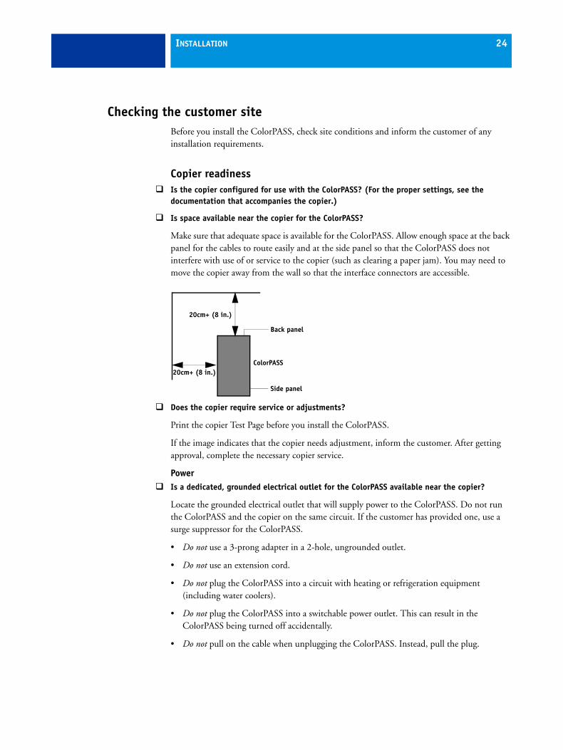
Is space available near the copier for the ColorPASS?
Make sure that adequate space is available for the ColorPASS. Allow enough space at the back panel for the cables to route easily and at the side panel so that the ColorPASS does not interfere with use of or service to the copier (such as clearing a paper jam). You may need to move the copier away from the wall so that the interface connectors are accessible.
Does the copier require service or adjustments?
Print the copier Test Page before you install the ColorPASS.
If the image indicates that the copier needs adjustment, inform the customer. After getting approval, complete the necessary copier service.
PowerIs a dedicated, grounded electrical outlet for the ColorPASS available near the copier?
Locate the grounded electrical outlet that will supply power to the ColorPASS. Do not run the ColorPASS and the copier on the same circuit. If the customer has provided one, use a surge suppressor for the ColorPASS.
• Do not use a 3-prong adapter in a 2-hole, ungrounded outlet.
• Do not use an extension cord.
• Do not plug the ColorPASS into a circuit with heating or refrigeration equipment (including water coolers).
• Do not plug the ColorPASS into a switchable power outlet. This can result in the ColorPASS being turned off accidentally.
• Do not pull on the cable when unplugging the ColorPASS. Instead, pull the plug.
Back panel
Side panel
20cm+ (8 in.)
ColorPASS20cm+ (8 in.)
INSTALLATION 25
NetworkMake sure that the network is available at the time set for installation.
Verify with the network administrator that the network is functioning before you attach the ColorPASS.
Make sure that the configuration requirements specified in Configuration and Setup (which is part of the user documentation set) have been met for remote computers and the network.
Setting customer expectations
When the site is ready, installation of the ColorPASS takes about one hour. Inform the customer of the following:
• Some nodes on the network may be unavailable for up to one hour.
• The copier may be unavailable for up to one hour.
• The network administrator must be available during the installation for network connectivity.
Equipment downtime and impact on the network can be minimized if the network administrator installs a network connector for the ColorPASS and confirms network functionality with the connector in place before the date scheduled for the ColorPASS installation.
• The network administrator must make a networked computer available during the installation. The appropriate software must be installed in advance. Documentation for the networked computer and network operating software should be available.
• The network administrator must install the user software shipped with the ColorPASS onto networked Windows and Mac OS computers that print to the ColorPASS (user documentation is also included).
NOTE: This document covers hardware installation and service and provides general information about connecting the ColorPASS to the customer’s network. Network Setup and configuration information exceeds the scope of this document. For Network Setup and configuration information, refer the network administrator to Configuration and Setup, which is part of the user documentation set.
INSTALLATION 26
Unpacking the ColorPASSThe ColorPASS is assembled and shipped from the factory with all necessary cables (except the network cable) and documentation (see page 27).
Never lift the ColorPASS by grasping the top panel. The top panel does not support the weight of the system.
AVERTISSEMENT: Ne jamais soulever le serveur d'impression par sa partie supérieure : celle-ci ne peut pas supporter le poids du système.
AVVERTENZA: Il server di stampa non deve essere mai sollevato afferrandolo dal pannello superiore, in quanto quest'ultimo non può sostenere il peso dell'intero sistema.
WARNUNG: Heben Sie den Druckserver nicht an der oberen Gehäuseabdeckung an. Die obere Gehäuseabdeckung ist nicht dafür ausgelegt, das Gesamtgewicht des Systems zu tragen.
ADVERTENCIA: No levante nunca el servidor de impresión agarrándolo por el panel superior. El panel superior no soporta el peso del sistema.
AVISO: Nunca erga o servidor de impressão pelo painel superior. O painel superior não suporta o peso do sistema.
WAARSCHUWING: Til de afdrukserver nooit op door het bovenpaneel vast te nemen. Het bovenpaneel kan het gewicht van het systeem niet dragen.
TO UNPACK THE COLORPASS
1 Open the box and remove the packing material.
Save the original boxes and packing material, in case you need to transport the ColorPASS at a later date.
2 Remove the contents from the top container. Inspect the contents for visible damage. The top container should include the following items:
• Bags containing one copier interface cable, one command/status crossover cable, and one power cable
• Fiery SeeQuence Suite (includes a dongle, Adobe Acrobat/PitStop DVD, and documentation)
• Quick Setup
• Customer media pack (for more information, see page 9)
3 Set aside the remaining components from the top container.
4 Remove the top container and any packing material.
Set aside the packing material and note the orientation of the ColorPASS inside the shipping container, in case you need to repack it later.
INSTALLATION 27
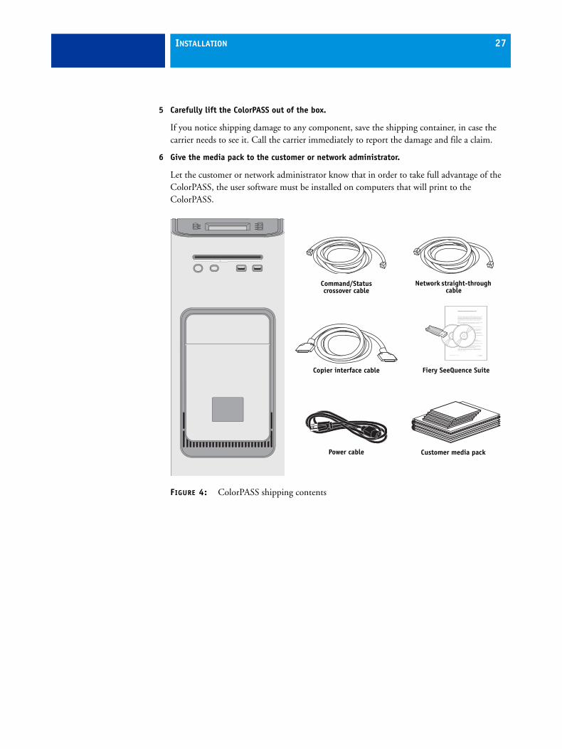
5 Carefully lift the ColorPASS out of the box.
If you notice shipping damage to any component, save the shipping container, in case the carrier needs to see it. Call the carrier immediately to report the damage and file a claim.
6 Give the media pack to the customer or network administrator.
Let the customer or network administrator know that in order to take full advantage of the ColorPASS, the user software must be installed on computers that will print to the ColorPASS.
FIGURE 4: ColorPASS shipping contents
Installing and Enabling Fiery SeeQuence Suite
Part Number: 4508991814 January 2010
Copyright 2010 © Electronics for Imaging, Inc.
This document describes how to install and enable Fiery SeeQuence Suite software, consisting of Fiery SeeQuence Impose and Fiery SeeQuence Compose, dongle-protected optional upgrade kits for Command WorkStation that work in conjunction with Adobe Acrobat and the Enfocus PitStop plug-in. You must install a kit-specific dongle on each client workstation that runs Fiery SeeQuence. This document explains how to install the dongle and the software.
NOTE: The terms “SeeQuence Impose” and “SeeQuence Compose” are used in this document to refer to Fiery SeeQuence Impose and Fiery SeeQuence Compose, respectively.
About SeeQuence Suite softwareFiery SeeQuence Suite software comprises integrated job preparation tools that allow you to do the following:
• SeeQuence Impose applies imposition layouts to jobs for custom printing, binding, and trimming. It also applies impositions to variable data jobs and saves imposed jobs as PDF files.
• SeeQuence Compose allows you to define the chapter divisions of a job, print ranges of pages on varying types of media, insert blank media between pages, and insert tab media containing text labels (if the copier supports tab printing).
• Preview provides a pre-RIP job preview and allows you to integrate SeeQuence Impose and SeeQuence Compose features in the same workflow.
About SeeQuence Suite kitsFiery SeeQuence Suite is available in the following optional kit configurations:
• Fiery SeeQuence Impose kit (includes the Adobe Acrobat/Enfocus PitStop DVD and a SeeQuence Impose dongle)
• Fiery SeeQuence Compose kit (includes the Adobe Acrobat/Enfocus PitStop DVD and a SeeQuence Compose dongle)
• Fiery SeeQuence Suite kit, which includes both SeeQuence Impose and SeeQuence Compose (includes the Adobe Acrobat/Enfocus PitStop DVD and SeeQuence Suite dongle, a single dongle that enables both Impose and Compose)
SeeQuence Impose and SeeQuence Compose are supported on Windows and Mac OS computers. For information about system requirements, see “Minimum requirements for a client workstation” on page 2.
Command/Status crossover cable
Power cable Customer media pack
Copier interface cable Fiery SeeQuence Suite
Network straight-through cable

INSTALLATION 28
Connecting the ColorPASS You are now ready to make the following connections:
• Optional monitor, keyboard, and mouse (if present)
• Optional dongle (if present)
• Power cable connection
• Copier interface cable connection
• Scan crossover cable connection
• Network cable connection
For detailed information about the monitor, keyboard, and mouse, see the documentation that accompanies the optional kit.
Follow standard ESD precautions when handling components.
FIGURE 5: ColorPASS connections
Front panel Back panel
USB ports
Power button
Control panel
DVD drivePower connector
USB ports (x2)
Network port (RJ-45)
Command/Status port (RJ-45)
USB ports (x4)
DVI port
Copier interface port
Reset button
NOTE: Use the reset button only if the system is unresponsive to keyboard or
Eject button
Power switch

INSTALLATION 29
TO CONNECT POWER
1 Connect the recessed end of the ColorPASS power cable to the power connector on the back of the ColorPASS (see Figure 5 on page 28).
2 Connect the other end of the ColorPASS power cable to a power outlet.
TO CONNECT TO THE COPIER
1 Make sure that the ColorPASS and the copier are powered off.
2 Connect one end of the copier interface cable to the ColorPASS.
3 Connect the other end of the copier interface cable to the copier.
Tighten the screws completely on both ends of the cable.
4 Connect the scan crossover cable to the scan ports on the ColorPASS and the copier.
NOTE: The straight-through network cable at the customer site and the scan crossover cable included with the ColorPASS look similar, but are not interchangeable. Make sure that you connect the scan crossover cable to the lower RJ-45 port on the ColorPASS back panel (see Figure 5 on page 28 and Figure 6).
FIGURE 6: Straight-through and crossover Ethernet cables
1 2 3 4 1 2 3 4=
Straight-through cable:wire arrangements are identical on both connectors
Crossover cable:wire arrangements are different
Align cables side by side and examine wires.
INSTALLATION 30
TO CONNECT TO THE NETWORK
1 Make sure that the ColorPASS is powered off.
2 Connect the network cable to the upper RJ-45 network port on the back of the ColorPASS (see Figure 5 on page 28).
The ColorPASS provides twisted pair connectivity to an Ethernet network. When the network cable is connected, the Ethernet interface automatically detects the speed of the network environment. Depending on your network speed, the following unshielded twisted pair (UTP) network cables are supported:
• 10BaseT: Category 3 or higher
• 100BaseTX: Category 5 or higher (4-pair/8-wire, short-length)
• 1000BaseT: Category 5e or higher (4-pair/8-wire, short-length)
After power on, the network administrator should perform Network Setup, verify the network connection, verify that the ColorPASS appears in the list of printers, and then print a few test documents from a networked computer that will use the ColorPASS. For more information, see Configuration and Setup, which is part of the user documentation set.
NOTE: The straight-through network cable at the customer site and the scan crossover cable included with the ColorPASS look similar, but are not interchangeable. Make sure that you connect the network cable to the upper RJ-45 port on the ColorPASS back panel (see Figure 5 on page 28 and Figure 6 on page 29).

INSTALLATION 31
Completing installation and starting upTo finish the installation of the ColorPASS at the customer site, make sure to do the following:
1 Make sure that the copier is powered on.
2 Power on the ColorPASS (see page 28).
Make sure that the power cord is attached and that the power switch on the back panel is in the ON position. Press the power button on the front panel once and release the button. The power supply automatically senses the correct voltage.
3 Wait for the ColorPASS to power on and for the Info screen to display Idle on the copier touch panel:
The ColorPASS takes approximately two minutes to power on and display Idle on the Info screen of the copier touch panel.
While the ColorPASS is booting, the following message displays on the copier touch panel: “Wait a while. (Check the power source of the print server behind the main unit and cable connection if the display does not change in a moment.)” If the message remains for longer than two minutes, verify that the copier interface cable is connected correctly to the copier.
4 Perform any required system software upgrades.
For instructions, see the documentation that accompanies the ColorPASS service upgrade.
Updates to Fiery Server Software may be available for the ColorPASS from a variety of sources (for example, System Updates (see page 110), patches provided on CD, or patches downloaded by the customer).
Windows operating system updates should be obtained from Microsoft directly. Because such updates are available directly from Microsoft, EFI does not maintain or provide them via the System Updates feature.
5 Print a Test Page and a Configuration page and ask the customer to verify the output.
6 If the ColorPASS requires a static IP address (for example, in a non-DHCP network environment), work with the network administrator to configure it as described on page 31.
7 Ask the network administrator to perform Setup and to print some test documents over the network.
8 Store the output and the current Configuration page(s) near the copier.
9 Inform the site administrator that the ColorPASS user software must be installed on networked computers that print to the ColorPASS.
10 Ask the site administrator to make sure that all media (DVDs and/or CDs) shipped with the ColorPASS is stored in a safe location, accessible to you.

USING THE COLORPASS 32
USING THE COLORPASS
This chapter includes the following information:
• Using the ColorPASS Control Panel
• Using the copier touch panel
• Checking Network status LEDs
• Shutting down and restarting the ColorPASS
Overview of the ColorPASS user interfacesTwo main user interfaces are available for the ColorPASS:
• The Control Panel on the front of the ColorPASS (see following figure)
• The touch panel on the copier (see page 35)
NOTE: A third user interface—the Fiery Advanced Controller Interface (FACI), which includes a monitor, keyboard, and mouse—is sold separately as an optional kit.
Using the ColorPASS Control PanelThe Control Panel on the front of the ColorPASS allows you to do the following:
• Eject CDs and DVDs. (On some systems, a hardware eject button is also provided below the disc slot.)
• Shut down, restart, or reboot the ColorPASS (see page 41).
• Interact with the ColorPASS during software installation (see page 104)..
FIGURE 7: ColorPASS Control Panel
Display window
Line selection buttons
Up buttonFirst
Fourth
Menu button
Down button
Activity light

USING THE COLORPASS 33
Buttons
Activity light
The activity light on the ColorPASS Control Panel indicates current ColorPASS activity. If the light is:
Line selection buttons
Use the four line selection buttons on the right side of the Control Panel to select the command displayed on the corresponding line of the LCD display.
Up and Down buttons
Use these buttons to scroll to different screens in multi-screen lists or prompts.
Menu button Press this button to view the Eject CD/DVD, Restart Server, Shut Down System, and Reboot System options.
Flashing amber The ColorPASS is starting up and the BIOS has established communication with the User Interface Board (UIB).
Flashing green The ColorPASS is continuing startup and the Windows operating system has established communication with the UIB.
Solid green The ColorPASS is powered on and in the Idle state.
Solid amber The ColorPASS is powered off, but the AC power cable is plugged into the power source. The Control Panel LCD continues to draw power when the ColorPASS is off.
Flashing orsolid red
An error has caused printing to be disabled.
No light The ColorPASS is powered off and the AC power cable is not connected to a power source.
USING THE COLORPASS 34
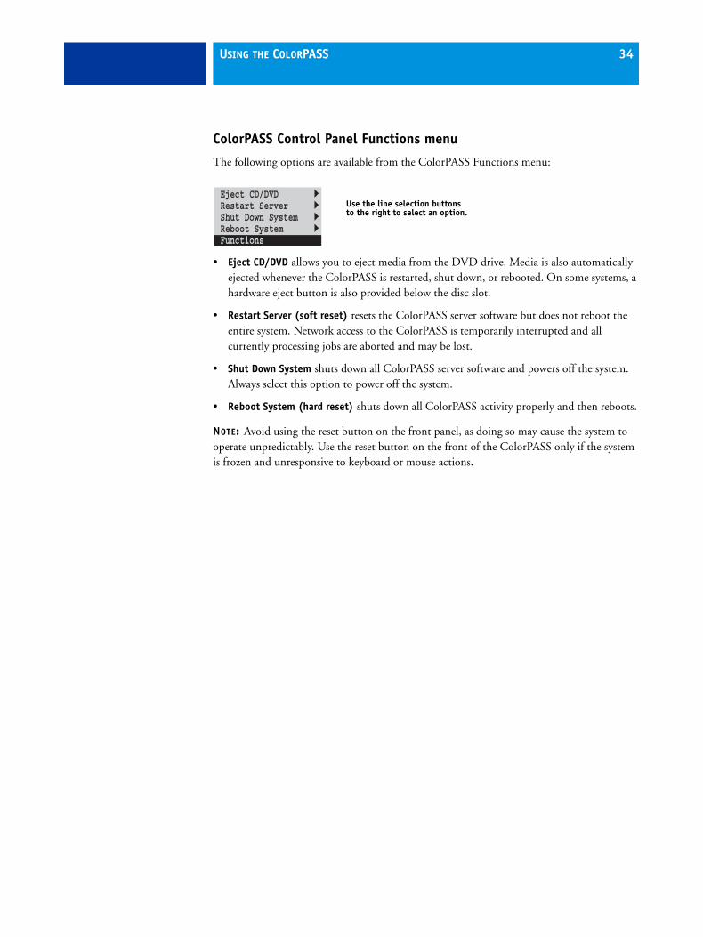
ColorPASS Control Panel Functions menu
The following options are available from the ColorPASS Functions menu:
• Eject CD/DVD allows you to eject media from the DVD drive. Media is also automatically ejected whenever the ColorPASS is restarted, shut down, or rebooted. On some systems, a hardware eject button is also provided below the disc slot.
• Restart Server (soft reset) resets the ColorPASS server software but does not reboot the entire system. Network access to the ColorPASS is temporarily interrupted and all currently processing jobs are aborted and may be lost.
• Shut Down System shuts down all ColorPASS server software and powers off the system. Always select this option to power off the system.
• Reboot System (hard reset) shuts down all ColorPASS activity properly and then reboots.
NOTE: Avoid using the reset button on the front panel, as doing so may cause the system to operate unpredictably. Use the reset button on the front of the ColorPASS only if the system is frozen and unresponsive to keyboard or mouse actions.
Eject CD/DVDRestart ServerShut Down SystemReboot SystemFunctions
Use the line selection buttons to the right to select an option.
USING THE COLORPASS 35
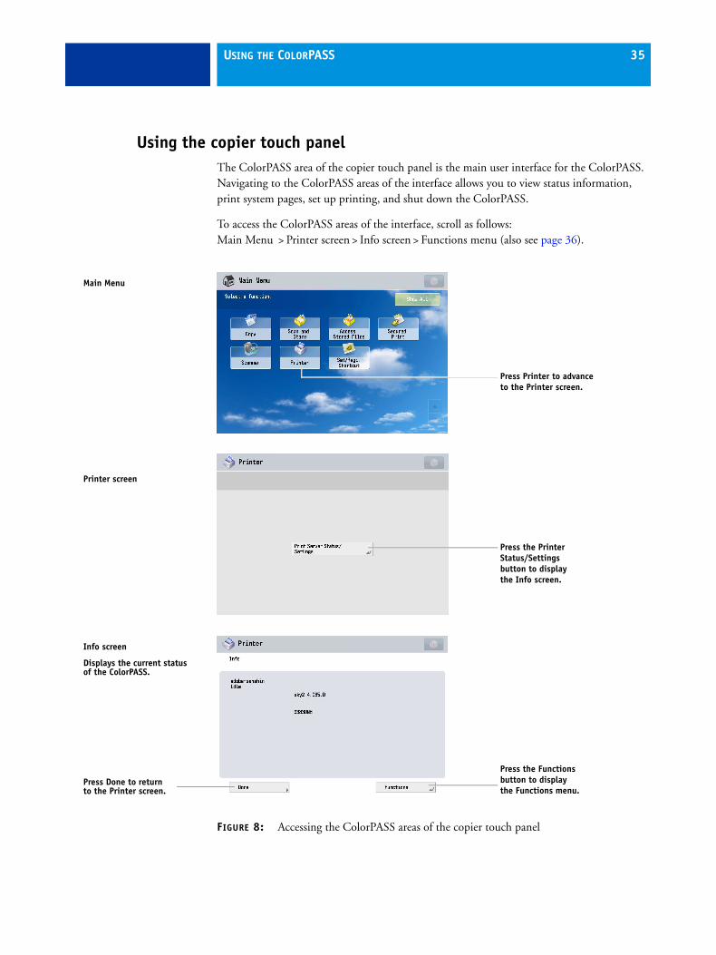
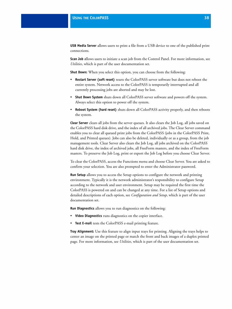
Using the copier touch panelThe ColorPASS area of the copier touch panel is the main user interface for the ColorPASS. Navigating to the ColorPASS areas of the interface allows you to view status information, print system pages, set up printing, and shut down the ColorPASS.
To access the ColorPASS areas of the interface, scroll as follows:Main Menu > Printer screen > Info screen > Functions menu (also see page 36).
FIGURE 8: Accessing the ColorPASS areas of the copier touch panel
Main Menu
Press Printer to advance to the Printer screen.
Press the Printer Status/Settings button to display the Info screen.
Press the Functions button to display the Functions menu.
Info screen
Displays the current status of the ColorPASS.
Printer screen
Press Done to return to the Printer screen.

USING THE COLORPASS 36
ColorPASS copier touch panel Functions menu
The ColorPASS Functions menu, accessible from the copier touch panel allows you to perform a variety of administrative functions that do not affect the print jobs of other users. The functions available from the Functions menu are described on page 37. Many of these functions are also available from Command WorkStation.
FIGURE 9: Using the ColorPASS Functions menu from the copier touch panel
Use the selection buttons on the right to select an option.
Use the up and down buttons to scroll through the list of functions.
Press the Done button to return to the Printer screen.

USING THE COLORPASS 37
Print Pages enables you to print system pages from the ColorPASS (see page 39). You can print the following pages from the submenu that appears:
• Test Page enables you to confirm that the ColorPASS-to-copier connection is functioning properly. The Test Page provides sample images that you can use to troubleshoot the ColorPASS. The following information is also listed: Server name, printer model, output profile, calibration information, RGB source, rendering style, date and time printed, CMYK simulation, simulation method, and compression information.
When you print a Test Page to confirm that the ColorPASS-to-copier connection is functioning properly, keep in mind that:
All color patches should be visible, even though they may be very faint in the 5% and 2% range.
Each color’s patch set should show uniform gradation from patch to patch as the color lightens from 100% to 0%.
Poor image quality may indicate a need to calibrate the system or service the copier. Information on the Test Page includes the date and time of the last calibration so that the Test Page can be kept for future reference. For more information, see Color Printing, which is part of the user documentation set.
• Configuration prints the current server and device configuration. This includes information about all current Setup settings, calibration profiles, and the Ethernet address of the ColorPASS. The Configuration page also provides version information for the BIOS chip and information about any installed options or special features included in the ColorPASS.
Printing the Configuration page can also be helpful during installation, Setup, and service. After installing the ColorPASS (including connecting to the network) and before default settings are changed in Run Setup, you can obtain a record of the defaults by printing the Configuration page. Before you perform any service procedure, print the ColorPASS Configuration page, if possible, so that you can return the settings to their former configuration, if necessary.
• Job Log prints a log of the most recent jobs printed on the ColorPASS. By default, the Job Log lists the last 55 jobs. For more information about the Job Log, see Configuration and Setup, which is part of the user documentation set.
• Color Charts prints the color reference charts. These pages include swatches of the RGB, CMY, and PANTONE colors available from the ColorPASS.
• Font List: A list of all fonts resident on the ColorPASS hard disk drive.
• E-mail Log prints a log of the last 55 e-mail transmissions to or from the ColorPASS. The E-mail printing feature must be enabled in Setup before the E-mail Log can be printed. For more information, see Configuration and Setup, which is part of the user documentation set.
• FTP Log lists jobs scanned on the copier and sent to the FTP site designated in the Setup options. The log is available only when Scan to FTP is enabled in Setup. For more information, see Configuration and Setup, which is part of the user documentation set.
USING THE COLORPASS 38
USB Media Server allows users to print a file from a USB device to one of the published print connections.
Scan Job allows users to initiate a scan job from the Control Panel. For more information, see Utilities, which is part of the user documentation set.
Shut Down: When you select this option, you can choose from the following:
• Restart Server (soft reset) resets the ColorPASS server software but does not reboot the entire system. Network access to the ColorPASS is temporarily interrupted and all currently processing jobs are aborted and may be lost.
• Shut Down System shuts down all ColorPASS server software and powers off the system. Always select this option to power off the system.
• Reboot System (hard reset) shuts down all ColorPASS activity properly, and then reboots the system.
Clear Server clears all jobs from the server queues. It also clears the Job Log, all jobs saved on the ColorPASS hard disk drive, and the index of all archived jobs. The Clear Server command enables you to clear all queued print jobs from the ColorPASS (jobs in the ColorPASS Print, Hold, and Printed queues). Jobs can also be deleted, individually or as a group, from the job management tools. Clear Server also clears the Job Log, all jobs archived on the ColorPASS hard disk drive, the index of archived jobs, all FreeForm masters, and the index of FreeForm masters. To preserve the Job Log, print or export the Job Log before you choose Clear Server.
To clear the ColorPASS, access the Functions menu and choose Clear Server. You are asked to confirm your selection. You are also prompted to enter the Administrator password.
Run Setup allows you to access the Setup options to configure the network and printing environment. Typically it is the network administrator’s responsibility to configure Setup according to the network and user environment. Setup may be required the first time the ColorPASS is powered on and can be changed at any time. For a list of Setup options and detailed descriptions of each option, see Configuration and Setup, which is part of the user documentation set.
Run Diagnostics allows you to run diagnostics on the following:
• Video Diagnostics runs diagnostics on the copier interface.
• Test E-mail tests the ColorPASS e-mail printing feature.
Tray Alignment: Use this feature to align input trays for printing. Aligning the trays helps to center an image on the printed page or match the front and back images of a duplex printed page. For more information, see Utilities, which is part of the user documentation set.

USING THE COLORPASS 39
Calibration allows the customer to calibrate the ColorPASS using AutoCal. For more information, see Color Printing, which is part of the user documentation set.
System Updates allows customers to schedule and accept installation of certain software updates from a secure site on the Internet. By default, the feature is configured to display a notification on the monitor (if the FACI option is present) that software updates are available for the ColorPASS. You can also check for system updates via the monitor (if present) by choosing Start > All Programs > Fiery > System Updates, and then clicking Check Now. Depending on how it is configured, System Updates operates manually or automatically. For more information about how to configure System Updates, see Configuration and Setup, which is part of the user documentation set.
Microsoft Windows operating system updates should be obtained from Microsoft directly. Because such updates are available directly from Microsoft, EFI does not maintain or provide them via the System Updates feature.
Print pages menu
This section describes how to print the Test Page and Configuration page from the Print Pages menu (described on page 37). To navigate to the Print Pages menu from the copier touch panel, scroll as follows: Main Menu > Printer screen > Info screen > Functions menu > Print Pages menu.
Printing the Configuration page can be helpful during installation, Setup, and service. After installing the ColorPASS (including connecting to the network), and before default settings are changed in Run Setup, you can obtain a record of the defaults by printing the Configuration page.
Before you perform any service procedure, you should print the ColorPASS Configuration page, if possible, so you are prepared to return the settings to their former configuration, if necessary.
Printing the Test Page indicates that the ColorPASS is functional and that the connection between the ColorPASS and the copier is working. If the Test Page fails to print, look up printing problems in “Table 3: ColorPASS error messages and condition” on page 122.

USING THE COLORPASS 40
TO PRINT A PAGE FROM THE PRINT PAGES MENU
1 If it is not powered on already, power on the copier and allow it to warm up.
2 If it is not powered on already, power on the ColorPASS using the power button on the front panel (see page 28) and allow it to start up completely (approximately three minutes).
3 Access the Info screen from the copier touch panel and make sure that Idle appears (see page 35).
If Printing or RIPping appears, the ColorPASS is processing. You must wait until the system finishes and reaches the Idle state.
4 Press the Functions button.
5 Press the Print Pages button, and then select the page that you want to print.
The ColorPASS sends the selected page(s) to the copier.
Network Status LEDsTwo LEDs next to the Ethernet connector indicate the network speed. When a data transfer occurs between the ColorPASS and the network, the appropriate LED(s) blink to indicate network activity. For additional network information, see Configuration and Setup, which is part of the user documentation set.
NOTE: The Ethernet network cable at the customer site and the Command/Status Ethernet Crossover cable included with the ColorPASS look similar, but are not interchangeable. Make sure that you attach the Command/Status Ethernet Crossover cable to the lower RJ-45 port and the network cable to the upper RJ-45 port on the ColorPASS back panel.
Network link speed LED 1 LED 2
10 Megabits/second Off Green
100 Megabits/second Green Green
1000 Megabits/second Amber Green
LED 2
LED 1
Ethernet network port(Upper RJ-45)

USING THE COLORPASS 41
Starting, shutting down, restarting, and rebooting The customer will generally leave the ColorPASS on all the time. Remember that when the ColorPASS is powered off, network access to the copier is interrupted. Power off the ColorPASS when you need to service it and before you remove or attach any cables to it.
Definitions
• Restart Server (soft reset) resets the ColorPASS server software, but does not reboot the entire system. Network access to the ColorPASS is temporarily interrupted and all currently processing jobs are aborted and may be lost.
• Reboot System (hard reset) shuts down all ColorPASS activity properly, and then reboots.
• Shut Down System shuts down all ColorPASS server software and powers off the system. Always select this option to power off the system.
NOTE: Use the reset button on the front of the ColorPASS only if the system is unresponsive to keyboard or mouse actions.
TO START THE COLORPASS
• Power on the ColorPASS by pressing the power button on the front panel.
The power supply automatically senses the correct voltage. Allow startup to proceed without interruption. Do not press any buttons on the Control Panel while the system is starting.
TO SHUT DOWN, RESTART, OR REBOOT FROM THE COLORPASS CONTROL PANEL
1 Make sure that the Info screen on the copier touch panel displays Idle (see page 35).
If Printing or Processing appears on the touch panel, the ColorPASS is processing. You must wait until the system finishes and reaches the Idle state.
If the system has just finished processing, wait at least five seconds after the system reaches Idle before beginning the shutdown procedure.
NOTE: Notify the network administrator before you remove the ColorPASS from the network.
2 At the ColorPASS Control Panel, press the Menu button.
3 Select Restart Server, Shut Down System, or Reboot System.
Before accessing internal components, make sure that all cables are disconnected from the back of the ColorPASS.
Eject CD/DVDRestart ServerShut Down SystemReboot SystemFunctions
Use the line selection button to the right to select Restart Server, Shut Down System, or Reboot System.

USING THE COLORPASS 42
TO SHUT DOWN, RESTART, OR REBOOT THE COLORPASS FROM THE COPIER TOUCH PANEL
1 Navigate to the Info screen on the copier touch panel (see page 35).
2 Make sure that the Info screen reads Idle.
If Printing or Processing appears on the touch panel, the ColorPASS is processing. You must wait until the system finishes and reaches the Idle state.
If the system has just finished processing, wait at least five seconds after the system reaches Idle before beginning the shutdown procedure.
NOTE: Notify the network administrator before you remove the ColorPASS from the network.
3 Press the Functions button to display the Functions menu.
4 Press the Shut Down button.
5 Select Restart Server, Shut Down System, or Reboot System.
Before accessing internal components, make sure that all cables are disconnected from the back of the ColorPASS.
Use the line selection buttons to select Restart Server, Shut Down System, or Reboot System.

SERVICE PROCEDURES 43
SERVICE PROCEDURES
Generally, the ColorPASS requires no regular service or maintenance. Use the procedures in this chapter to inspect, remove, reseat, and replace major hardware components, as well as install system software.
OverviewThis chapter includes information about servicing the following components:
• Boards and cables
• Motherboard components (DIMMs, CPU, CMOS, jumpers, and battery)
• Fans
• Power supply
• Hard disk drive (HDD)
Replacement parts are available from your authorized service representative. The terms “replace” and “replacing” are used throughout this document to refer to the reinstallation of existing components. Install new components only when necessary. If you determine that a component that you have removed is not faulty, reinstall it.
When performing the service procedures described in this chapter, follow the precautions listed on page 14.
The tools required to service the ColorPASS are listed on page 18.

SERVICE PROCEDURES 44
ColorPASS overview diagrams
The following figures provide an overview of ColorPASS components.
FIGURE 10: Front and back panels
Front panel Back panel
USB ports
Power button
Control panel
DVD drive Power connector
Network port
USB ports (x4)
USB ports (x2)
Copier interface port
Reset button
NOTE: Use the reset button only if the system is unresponsive to keyboard or
Eject button
Power switch
Command/Status port
DVI port

SERVICE PROCEDURES 45
FIGURE 11: Back panel and internal side view
Key
1. Power connector2. USB ports (x4)3. Network port4. USB ports (x2)5. Command/Status port6. DVI port
7. Copier interface board (PCI-E6)8. CPU cooling assembly9. Power supply
10. DIMM slots11. DVD drive12. Removable drive (option)
13. Hard disk drive in bracket14. Motherboard15. Front fan
NOTE: Cables, UIB, and front panel USB ports are not shown.
1
14 15
13
12
11
10
2
3
4
5
6
7
8
9
7
6

SERVICE PROCEDURES 46
FIGURE 12: Exploded view of ColorPASS components
21
1
12
13
8
1015
17
16
522
23
14
7
3
2
46
9
1118
19
20
24
Key
1. Top panel plug2. Top panel3. User interface board (UIB)4. Component sled5. Switch bank assembly6. DVD drive7. Front panel8. Upper faceplate
9. UIB cable10. Hard disk drive bracket11. Hard disk drive12. Side panel (left)13. Hard disk drive data cables14. DVD drive power/data combination cable15. CPU cooling assembly16. Copier interface board
17. DIMMs18. CPU19. Battery20. Motherboard21. Fan22. Chassis23. Power supply24. Side panel (right)
NOTE: UIB buttons, CPU fan cable, tie-wraps, cable clamps, dongle(s), and external cables are not shown.

SERVICE PROCEDURES 47
Cable key From To
1. Power supply cable Power supply a. CPU power connector (PW1)
b. Motherboard power connector (PW2)
c. DVD drive power connector (combined with data)
d. Hard disk drive power connector
2. Front panel USB port cables Front panel Motherboard connectors J22, J35 (see detail above)
3. UIB cable User interface board Motherboard connector USB 3 (see detail above)
4. Power and reset cables Front panel Motherboard connector JP4 (see detail above)
1b
1c
9
5
NOTE: Power supply, DIMMs, and copier interface are not shown.
1a
8
4
7
6
1d
3
2
2
3
4
5
6
7
8

SERVICE PROCEDURES 48
FIGURE 13: Power and data cable connections in the ColorPASS
Accessing internal componentsThis section describes how to shut down and open the ColorPASS. Always use the following procedures when opening the ColorPASS for inspection or service.
Shutting down the system
You can shut down the ColorPASS from the ColorPASS Control Panel or the copier touch panel. When shutting down the ColorPASS, do the following:
• Remove the power cable from the back panel before removing or connecting interface cables or accessing the internal components.
• Remember that when the ColorPASS is powered off, network access to the copier is interrupted. Always obtain permission from the network administrator before you take the ColorPASS off the network.
• If you are cycling power, wait at least 10 seconds before powering back on.
• If you are unable to shut down the ColorPASS through the Control Panel or the copier touch panel, power off by holding down the power button on the front of the ColorPASS for up to eight seconds.
• Using the reset button may cause the system to operate unpredictably. Use the reset button on the front of the ColorPASS only if the system is unresponsive to keyboard or mouse actions.
5. Speaker cable Front panel Motherboard connector J40 (see detail above)
6. Front panel fan cable Front panel fan Motherboard connector FAN 4 (see detail above)
7. DVD drive power/data combo cable DVD drive Motherboard connector SATA 0 (see detail above)
8. Hard disk drive data cable Hard disk drive Motherboard connector SATA 1 (see detail above)
9. CPU fan cable CPU fan Motherboard connector FAN 1 (If present, keep the cable cover on the CPU fan cable.)
Cable key From To
SERVICE PROCEDURES 49
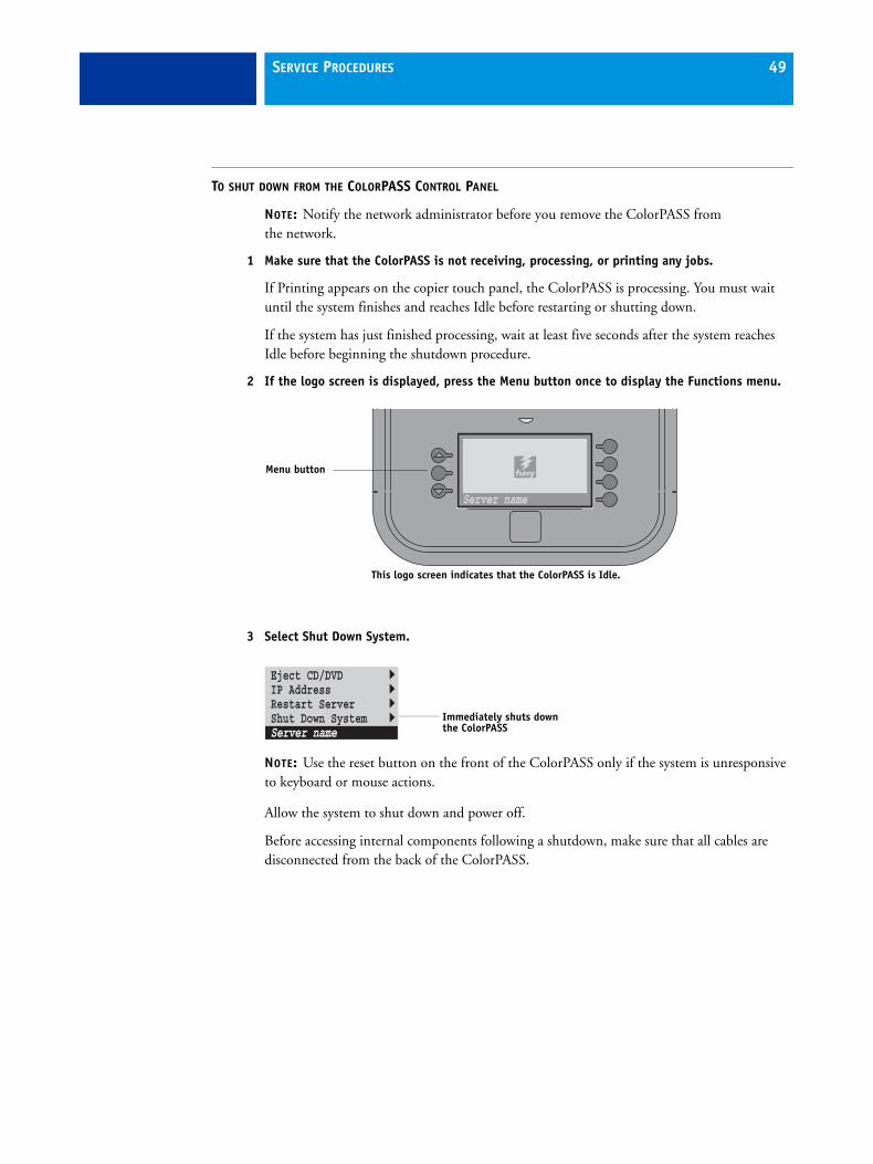
TO SHUT DOWN FROM THE COLORPASS CONTROL PANEL
NOTE: Notify the network administrator before you remove the ColorPASS from the network.
1 Make sure that the ColorPASS is not receiving, processing, or printing any jobs.
If Printing appears on the copier touch panel, the ColorPASS is processing. You must wait until the system finishes and reaches Idle before restarting or shutting down.
If the system has just finished processing, wait at least five seconds after the system reaches Idle before beginning the shutdown procedure.
2 If the logo screen is displayed, press the Menu button once to display the Functions menu.
3 Select Shut Down System.
NOTE: Use the reset button on the front of the ColorPASS only if the system is unresponsive to keyboard or mouse actions.
Allow the system to shut down and power off.
Before accessing internal components following a shutdown, make sure that all cables are disconnected from the back of the ColorPASS.
This logo screen indicates that the ColorPASS is Idle.
Server name
Menu button
Eject CD/DVDIP AddressRestart ServerShut Down SystemServer name
Immediately shuts down the ColorPASS
SERVICE PROCEDURES 50
TO SHUT DOWN FROM THE COPIER TOUCH PANEL
NOTE: Notify the network administrator before you remove the ColorPASS from the network.
1 Make sure that the ColorPASS is not receiving, processing, or printing any jobs.
If Printing appears on the copier touch panel, the ColorPASS is processing. You must wait until the system finishes and reaches Idle before restarting or shutting down.
If the system has just finished processing, wait at least five seconds after the system reaches Idle before beginning the shutdown procedure.
2 On the copier touch panel, tap Printer, and then tap Printer Server Status/Settings.
NOTE: If Printer does not display, tap Show All.
3 Tap Functions.
4 Tap the down arrow to scroll to Shut Down.
5 From the Shut Down screen, choose Shut Down System.
6 Turn off the copier.
Allow the system to shut down and power off.
Before accessing internal components, make sure that all cables are disconnected from the back of the ColorPASS.

SERVICE PROCEDURES 51
Opening the ColorPASS
To service internal components, open the ColorPASS as described in the following procedure.
Never lift the ColorPASS by grasping the top panel. The top panel does not support the weight of the system.
AVERTISSEMENT: Ne jamais soulever le serveur d'impression par sa partie supérieure : celle-ci ne peut pas supporter le poids du système.
AVVERTENZA: Il server di stampa non deve essere mai sollevato afferrandolo dal pannello superiore, in quanto quest'ultimo non può sostenere il peso dell'intero sistema.
WARNUNG: Heben Sie den Druckserver nicht an der oberen Gehäuseabdeckung an. Die obere Gehäuseabdeckung ist nicht dafür ausgelegt, das Gesamtgewicht des Systems zu tragen.
ADVERTENCIA: No levante nunca el servidor de impresión agarrándolo por el panel superior. El panel superior no soporta el peso del sistema.
AVISO: Nunca erga o servidor de impressão pelo painel superior. O painel superior não suporta o peso do sistema.
WAARSCHUWING: Til de afdrukserver nooit op door het bovenpaneel vast te nemen. Het bovenpaneel kan het gewicht van het systeem niet dragen.
TO OPEN THE COLORPASS
1 Shut down the ColorPASS (see page 48).
2 Remove all cables from the back of the ColorPASS.
3 If the ColorPASS is mounted on the optional furniture, and the optional monitor is attached, perform the disassembly instructions in “Servicing the ColorPASS with furniture” on page 134.
4 Remove all panels necessary to access the component that you need to service.
For guidelines on which panels to remove, see the service procedure for the component that you want to access.
NOTE: When removing multiple panels from the ColorPASS, use the following order:
• Left panel (see page 52)
• Right panel (see page 52)
• Front panel (see page 53)
• Top panel (see page 54)
NOTE: When replacing panels, reverse the order.
5 Place the ColorPASS on a flat surface. Attach an ESD wrist strap before handling internal parts (see “Precautions” on page 14).
6 Carefully position the ColorPASS so that it is resting on its side and the internal components are facing up.
Place removed components on a grounded, antistatic surface.

SERVICE PROCEDURES 52
TO REMOVE AND REPLACE THE LEFT OR RIGHT PANEL
1 Remove the screws that secure the panel to the back of the chassis.
Set aside the screws so that you can replace them later.
2 Pull the back edge of the panel away from the chassis and lift the panel off the chassis.
FIGURE 14: Removing/replacing the side panels
3 To replace the panel, fit the front edge of the panel on the pivot post in the chassis.
4 Rotate the panel closed against the back of the chassis and replace the screws that you removed earlier.
Make sure not to damage cables as you replace the panel. Fold all cables inside the chassis before closing the panel against the chassis.
Pivot post inside chassis
Left side panel
Right side panel

SERVICE PROCEDURES 53
TO REMOVE AND REPLACE THE FRONT PANEL
NOTE: To remove the front panel, you must first remove the left and right panels.
1 Remove the upper faceplate from the front of the chassis.
Press down to release the two tabs that secure the upper faceplate to the front panel, and then carefully remove the upper faceplate from the front panel.
NOTE: You must remove the upper faceplate in order to remove the front panel from the chassis.
2 Pull outward on the six tabs that secure the front panel to the chassis, and then lift the panel off of the chassis.
First remove the two top tabs, then the two middle tabs, and then the two bottom tabs.
FIGURE 15: Removing/replacing the front panel
3 To replace the front panel, align the four cutouts in the panel with the power and reset buttons and front USB ports.
4 Press the panel against the chassis to snap it into place.
Snap the tabs in pairs (first the top tabs, then the middle tabs, and then the bottom tabs).
5 Replace the upper faceplate.
Insert the two standoffs at the base of the faceplate into the chassis, and then carefully press the faceplate against the chassis to lock the faceplate into place.
Upper faceplate
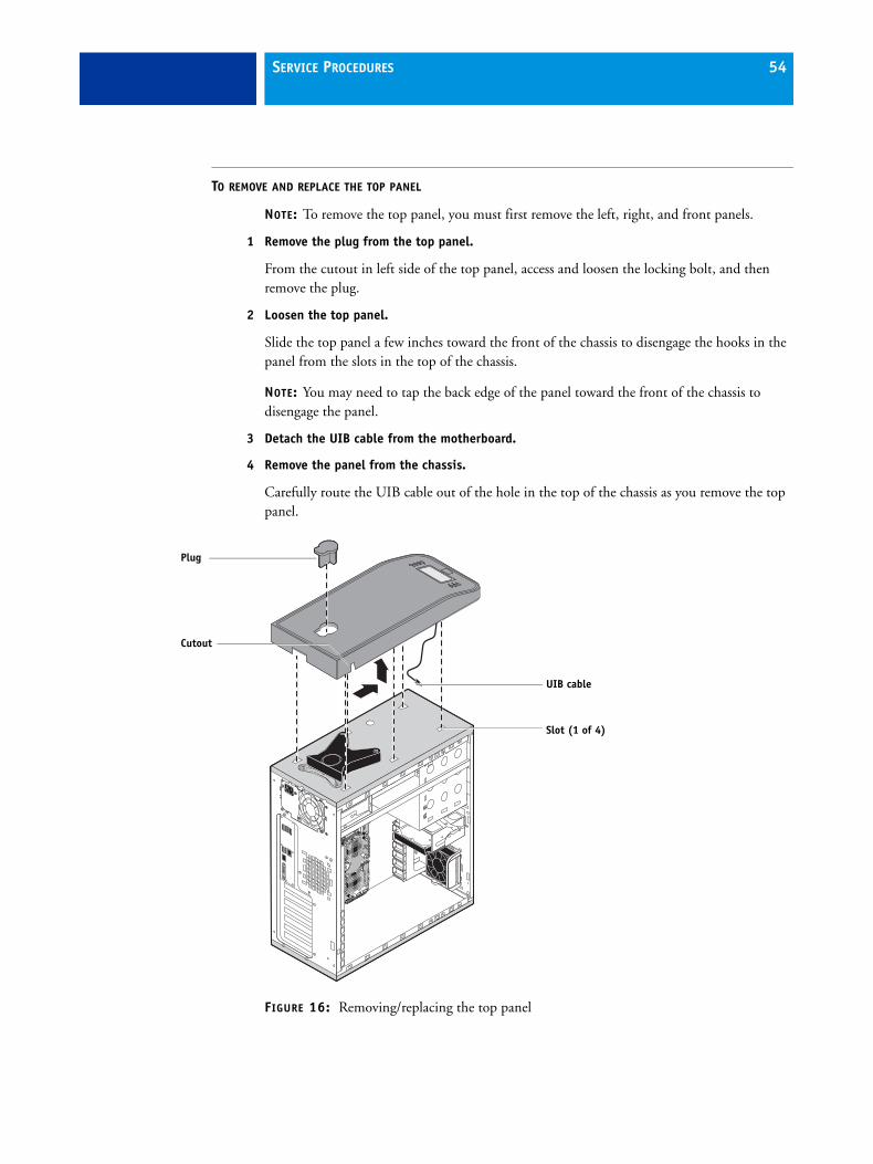
SERVICE PROCEDURES 54
TO REMOVE AND REPLACE THE TOP PANEL
NOTE: To remove the top panel, you must first remove the left, right, and front panels.
1 Remove the plug from the top panel.
From the cutout in left side of the top panel, access and loosen the locking bolt, and then remove the plug.
2 Loosen the top panel.
Slide the top panel a few inches toward the front of the chassis to disengage the hooks in the panel from the slots in the top of the chassis.
NOTE: You may need to tap the back edge of the panel toward the front of the chassis to disengage the panel.
3 Detach the UIB cable from the motherboard.
4 Remove the panel from the chassis.
Carefully route the UIB cable out of the hole in the top of the chassis as you remove the top panel.
FIGURE 16: Removing/replacing the top panel
Plug
Slot (1 of 4)
Cutout
UIB cable
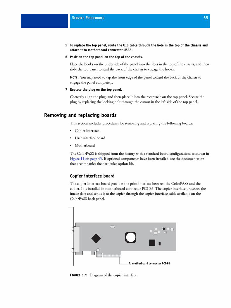
SERVICE PROCEDURES 55
5 To replace the top panel, route the UIB cable through the hole in the top of the chassis and attach it to motherboard connector USB3.
6 Position the top panel on the top of the chassis.
Place the hooks on the underside of the panel into the slots in the top of the chassis, and then slide the top panel toward the back of the chassis to engage the hooks.
NOTE: You may need to tap the front edge of the panel toward the back of the chassis to engage the panel completely.
7 Replace the plug on the top panel.
Correctly align the plug, and then place it into the receptacle on the top panel. Secure the plug by replacing the locking bolt through the cutout in the left side of the top panel.
Removing and replacing boardsThis section includes procedures for removing and replacing the following boards:
• Copier interface
• User interface board
• Motherboard
The ColorPASS is shipped from the factory with a standard board configuration, as shown in Figure 11 on page 45. If optional components have been installed, see the documentation that accompanies the particular option kit.
Copier interface board
The copier interface board provides the print interface between the ColorPASS and the copier. It is installed in motherboard connector PCI-E6. The copier interface processes the image data and sends it to the copier through the copier interface cable available on the ColorPASS back panel.
FIGURE 17: Diagram of the copier interface
To motherboard connector PCI-E6

SERVICE PROCEDURES 56
TO REMOVE THE COPIER INTERFACE BOARD
1 Shut down and open the ColorPASS (see pages 48 and 51).
To remove the copier interface board, you must remove the left panel.
2 Make sure that the copier interface cable is removed from the ColorPASS back panel.
3 Remove the board mounting bracket screw that attaches the copier interface to the chassis.
4 Remove the copier interface board from motherboard connector PCI-E6.
Grasp the copier interface board at the front and back edges and gently pull the board straight out of its motherboard connector.
5 Place the copier interface board in an antistatic bag.
TO REPLACE THE COPIER INTERFACE BOARD
1 Seat the copier interface board in connector PCI-E6 on the motherboard (the topmost connector), and then secure it to the chassis with the board mounting bracket screw that you removed earlier.
The copier interface board edge connector is keyed to fit in slot PCI-E6 only when properly oriented.
2 Reassemble the ColorPASS and verify its functionality (see page 103).
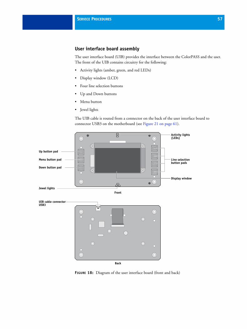
SERVICE PROCEDURES 57
User interface board assembly
The user interface board (UIB) provides the interface between the ColorPASS and the user. The front of the UIB contains circuitry for the following:
• Activity lights (amber, green, and red LEDs)
• Display window (LCD)
• Four line selection buttons
• Up and Down buttons
• Menu button
• Jewel lights
The UIB cable is routed from a connector on the back of the user interface board to connector USB3 on the motherboard (see Figure 21 on page 61).
FIGURE 18: Diagram of the user interface board (front and back)
Back
Front
Line selection button pads
UIB cable connector USB3
Activity lights (LEDs)
Display window
Up button pad
Menu button pad
Down button pad
Jewel lights

SERVICE PROCEDURES 58
TO REMOVE THE USER INTERFACE BOARD
1 Shut down and open the ColorPASS (see page 48).
To access the UIB, you must remove the left, right, front, and top panels.
NOTE: Be sure to detach the UIB cable from its connector on the motherboard, and then carefully route the cable out of the hole in the top of the chassis as you remove the top panel.
2 Turn the top panel over to expose its underside and place it on a padded surface.
3 Detach the UIB cable from the connector on the back of the UIB.
Detach the UIB cable by grasping the cable connector. Avoid pulling on the cable.
4 Remove the four screws that secure the UIB to the underside of the top panel.
5 Remove the UIB from the top panel. Be sure to remove the plastic lens that covers the display window of the UIB.
FIGURE 19: Removing/replacing the user interface board
6 If you are removing the UIB to replace it with a new board, remove the UIB buttons from the old UIB (see Figure 20 on page 59).
When removing the buttons, take care not to damage the pointed tabs that hold the buttons onto the UIB.
7 Place the UIB in an antistatic bag.
UIB cable connector
Screw (1 of 4)

SERVICE PROCEDURES 59
TO REPLACE THE USER INTERFACE BOARD
1 If you are installing a new UIB, correctly orient the UIB buttons, and then mount them on the new UIB.
The UIB buttons attach directly to the front of the UIB and extend through channels in the top panel. When correctly positioned, the buttons make contact with the button pads on the front of the UIB and provide users with manual status and control capability from the Control Panel.
Use needlenose pliers to pull the button tabs carefully through the anchoring holes in the UIB until the buttons are secured in place.
FIGURE 20: Removing/replacing the UIB buttons
2 Attach the UIB cable to the connector on the back of the UIB (see Figure 19 on page 58).
3 Turn the top panel over to expose its underside and place it on a padded surface.
4 Position the plastic lens around the display window of the UIB.
5 Secure the UIB to the underside of the top panel.
Grasp the UIB in one hand while using the other hand to hold the plastic lens steady against the UIB display window. Place the UIB in the mounting area of the top panel and carefully fit the buttons through the cutouts in the top panel as you hold the plastic lens in place.
Replace the four screws that secure the UIB to the underside of the top panel. Be sure to use the same screws that you removed earlier.
6 If you are replacing the UIB cable with a new cable, do the following:
If present, cut the clamp securing the old cable to the underside of the top panel and remove the old cable. Attach a new UIB cable to the connector on the UIB. If a new tie-wrap is included in the new UIB cable spare kit, use it to secure the new UIB cable to the underside of the top panel.
7 Replace the top panel (see page 54).
Route the UIB cable through the chassis and connect it to motherboard connector USB3 (see Figure 13 on page 48).
8 Reassemble the ColorPASS and verify its functionality (see page 103).

SERVICE PROCEDURES 60
MotherboardIf you are removing the motherboard in order to replace it with a new motherboard, review the troubleshooting and motherboard cautions on page 64.
The Intel Core i5-660 3.33GHz CPU mounted on the motherboard controls the image data transferred to and from the copier interface. The motherboard also controls hard disk drive functions and the communication between the ColorPASS and external devices. The motherboard has four DIMM sockets. Two sockets contain a 1GB DIMM, for a total of 2GB of memory (see Figure 24 on page 76). The motherboard also includes the following PCI expansion slots (from top to bottom):
• One PCI-E x16 slots with x8 signal (used for the copier interface)
• One PCI-E x8 slots with x4 signal (not used)
• One PCI-E x16 slots with x4 signal (not used)
• Two PCI-X 133/100/66MHz (not used)
Removing the motherboard
The motherboard attaches to the side of the chassis, below the power supply. Before you remove the motherboard, you must remove the following:
• The left panel
• All boards installed on the motherboard
• All cables connected to the motherboard(including the motherboard power cable, CPU power cable, front panel fan cable, hard disk drive data cable, DVD drive power and data combination cable, power button cable, reset button cable, speaker cable, front panel USB port cables, and UIB cable)
This section also includes information about the following:
• Replacing or adding DIMMs
• Replacing the CPU
• Replacing the battery
• Clearing the CMOS
• Jumper configurations
Follow standard ESD and other safety precautions when handling components (see page 14). During service to the motherboard, avoid using excessive force and always place the motherboard on a grounded, non-metallic, static-free surface. Never allow any metal to touch the solder contacts on the underside of the motherboard, especially beneath the battery socket. Improper handling can short-circuit and permanently damage the motherboard.

SERVICE PROCEDURES 61
FIGURE 21: Diagram of the ColorPASS motherboard
Key
1. USB ports (x4)
2. Network interface/USB ports (x2)
3. Command/Status port4. Monitor
5. CPU power (PW1)
6. Motherboard power (PW2)7. CPU, heatsink, CPU fan
8. Battery (BT1)
9. Copier interface board (PCI-E6)10. Empty PCI-E (J12)
11. Empty PCI-E (J11)
12. Empty PCI-E (J10)13. Empty PCI-X (J9)
14. DIMM 4
15. DIMM 316. DIMM 2
17. DIMM 1
18. CPU fan power (FAN 1)19. Not used
20. Speaker (J40)
21. UIB cable (USB3)22. SATA 3 (Not used)
23. SATA 0: DVD drive data connection
24. SATA 4 (Not used)25. SATA 1: Hard disk drive data connection
26. SATA 5 (Not used)
27. SATA 2 (Not used)28. Front panel USB port cable (USB2)
29. Front panel USB port cable (USB4)
30. PWR & RST (JP4)31. Front panel fan (FAN 4)
MH—Mounting holes
16
MHMH
MH
MHMH
MH
11
MH
MH
1
2
3
4
5
6
7
89
10
12
13
14
15
17
18
19
20
22
21
23
24 25
26 27
28 29 30 31

SERVICE PROCEDURES 62
TO REMOVE BOARDS AND CABLES FROM THE MOTHERBOARD
1 Shut down and open the ColorPASS (see pages 48 and 51).
To access the motherboard, you must remove the left side panel.
2 Remove all boards installed in slots on the motherboard.
Note the location of the slot where each board resides so that you can reinstall the board in the same slot later.
3 Remove the following cables from the old motherboard:
NOTE: First remove any plastic cable clamp(s) securing internal cables and reusable tie-wraps, if present.
• Front panel fan cable (FAN 4)
• Reset button cable (JP4)
• Power button cable (JP4)
• Speaker cable (JP5)
• UIB cable (USB3)
• Front panel USB port cables (USB2 and USB4)
• DVD drive cables:
– SATA data cable from motherboard connector SATA 0
– Power and data combination cable from the back of the DVD drive
• Hard disk drive cables:
– SATA data cable from motherboard connector SATA 1
– Power supply cable from the back of the hard disk drive
• Motherboard power cable (20-pin, PW2)
• CPU power cable (8-pin, PW1)
For motherboard connector locations, see Figure 21 on page 61.

SERVICE PROCEDURES 63
TO REMOVE THE MOTHERBOARD
NOTE: This procedure assumes that you have already performed the procedure “To remove boards and cables from the motherboard” on page 62.
1 Remove the hard disk drive bracket, with hard disk drive attached (see page 92).
Remove the screw that attaches the bracket to the shelf. Removing the hard disk drive and hard disk drive bracket provides the clearance necessary for removing the motherboard. You must also detach the hard disk drive power cable to remove the hard disk drive.
2 Remove the nine mounting screws securing the motherboard to the chassis (for screw locations, see Figure 21 on page 61).
3 Remove the motherboard from the chassis.
Lift the edge of the motherboard (see Figure 22). Make sure that the back panel connectors on the motherboard clear the chassis while you lift it out of the chassis. Do not touch the contacts and avoid using excessive force.
During service, avoid using excessive force and always place the motherboard on a grounded, non-metallic, static-free surface. Never allow any metal to touch the solder contacts on the underside of the motherboard, especially beneath the battery socket. Improper handling can short-circuit and permanently damage the motherboard.
FIGURE 22: Removing the motherboard
Lift the edge of the motherboard and remove it from the chassis.

SERVICE PROCEDURES 64
Replacing the motherboard
Follow the procedures in this section to replace the motherboard. Failure to follow the instructions in this section may corrupt the system (not easily repaired in the field) or result in an incomplete installation (see “Error messages” on page 75).
Troubleshooting cautions• Before deciding to install a new motherboard, consult “Troubleshooting” on page 111.
• Inspect all cables and internal components as described on pages 113 and 114. If these inspections do not solve the problem, locate symptoms in the troubleshooting table beginning on page 121 and perform the suggested actions in the order listed.
• If troubleshooting strategies (checking cables and connections, reinstalling system software, and so forth) do not solve the problem, and you suspect that the hard disk drive or the motherboard is faulty, always troubleshoot in the following order:
(Troubleshooting in the wrong order will cause the system to malfunction. In general, it is highly unlikely that both the hard disk drive and the motherboard are defective; therefore, avoid replacing both to solve one problem.)
– First, replace the hard disk drive and install system software.
Always replace a faulty hard disk drive with a new hard disk drive. Transferring a hard disk drive from one ColorPASS to another is incorrect and strongly discouraged.
– If the problem persists, reinstall the original hard disk drive in the system, and then replace the motherboard.

SERVICE PROCEDURES 65
Motherboard cautions
If you have exhausted all other troubleshooting remedies and determined that you need to install a new motherboard, be sure to observe the following cautions:
• Transfer the DIMMs, CPU, and CPU cooling assembly from the old motherboard onto the new motherboard.
• Do not transfer the BIOS chip from the old motherboard onto the new motherboard.
BIOS chips are not interchangeable.
• Do not reinstall system software at this time.
Reinstalling system software is not necessary when installing a new motherboard and can result in an error if done before transferring options to the new motherboard (described on page 71.)
• Before you use the one-time use dongle to transfer options (for example, Fiery Graphic Arts, Premium Edition, if applicable) to the new motherboard, enter Service Mode (see page 70) and make sure that the new motherboard solves the problem that you are troubleshooting.
The ColorPASS can remain in Service Mode indefinitely. Use Service Mode to carefully verify the new motherboard before transferring options to the new motherboard.
Transferring options to the new motherboard permanently customizes the new motherboard. Once customized, the motherboard cannot be returned to inventory or installed in another ColorPASS. If the new motherboard does not solve the problem in Service Mode, do not transfer options. Return the new motherboard and unexpended one-time use dongle to inventory.
• If you can verify in Service Mode that the new motherboard solves the problem that you are troubleshooting, transfer options to the new motherboard using the and one-time use dongle included with the new motherboard (see page 71).
• Do not remove the one-time use dongle while transferring options to the new motherboard.
Removing the one-time use dongle prematurely will corrupt the dongle and possibly damage the motherboard. If either become corrupted, you must contact your authorized service/support center and order a new replacement motherboard kit.

SERVICE PROCEDURES 66
TO REPLACE THE MOTHERBOARD
1 If you are installing a new motherboard, do the following:
• Unpack the new motherboard.
• Open the load plate covering the CPU socket (see page 80) and remove the protective plastic cover on the CPU socket on the new motherboard. Later, you will transfer the protective plastic cover to the CPU socket of the old motherboard to protect the circuitry.
• Remove the DIMMs from the old motherboard and install them on the new motherboard (see page 76).
• Remove the CPU and cooling assembly from the old motherboard and install them on the new motherboard (see page 78). Make sure that the cable cover (if present) remains on the cooling assembly fan cable when transferring the cooling assembly to the new motherboard.
When transferring the CPU to the new motherboard, make sure to use the fresh thermal compound that came with the new motherboard. For more information about the thermal compound, see page 81.
Do not transfer the BIOS chip from the old motherboard onto the new motherboard. Doing so can damage the ColorPASS. BIOS chips are not interchangeable.
2 Install the motherboard in the chassis.
Angle the motherboard so that the back panel connectors on the motherboard fit into the cutouts in the back of the chassis (see Figure 22 on page 63).
Make sure that the flexible grounding tabs on the cutouts for the network ports make contact with the outside of the ports. Do not allow the tabs to fold over or become bent inside the ports. The ports will not function if the tabs are placed improperly. Take care when lowering the new motherboard into the chassis. Do not strike the motherboard against the metal standoffs attached to the chassis, as doing so can damage the components on the underside of the motherboard.
3 Align the mounting holes on the motherboard with the standoffs located in the base of the chassis.
4 Secure the motherboard to the chassis using the nine mounting screws that you removed earlier.
Partially tighten each screw before completing tightening any one screw. Do not overtighten the screws; doing so could damage traces on the motherboard.
You are now ready to complete motherboard installation.

SERVICE PROCEDURES 67
TO REPLACE BOARDS, CABLES, AND COMPONENTS
1 Replace the hard disk drive bracket, with hard disk drive attached (see page 94).
You removed the hard disk drive bracket to provide clearance for removing the motherboard.
2 Replace the following cables:
• CPU power cable (8-pin, PW1)
• Motherboard power cable (20-pin, PW2)
• UIB cable (USB3; see detail below)
• Hard disk drive cables: SATA data cable to motherboard connector SATA 1
• DVD drive cables:
– Power and data combination cable to the back of the DVD drive
– SATA data cable to motherboard connector SATA 0
NOTE: Connect the thin, black SATA power cable connectors to the hard disk drive and DVD drive. Do not connect the white, 4-pin power cable connectors. Connecting both types of power cables will damage the hard disk drive and DVD drive.
• Front panel USB port cables (USB2 and USB4; see detail)
• Speaker cable (JP5; see detail)
Make sure that the small triangle on the cable connector is aligned with pin 1 on JP5.
• Power button cable (SSI CONN pins 11and 13; see detail)
Make sure that the small triangle on the cable connector is aligned with pin 11 on SSI CONN.
• Reset button cable (SSI CONN pins 15 and 17; see detail)
Make sure that the small triangle on the cable connector is aligned with pin 15 on SSI CONN.
• Front panel fan cable (J30; see detail)

SERVICE PROCEDURES 68
3 Secure cables as necessary with any plastic cable clamp that you may have removed earlier.
4 Replace the copier interface in motherboard connector PCI-E6 (see Figure 21 on page 61).
Make sure to install the board mounting bracket screw to secure the board to the chassis. Press down firmly on the top of the board as you insert the screw.
NOTE: Make sure that unused back panel slots are covered with slot covers. Uncovered slots reduce air flow and may cause the ColorPASS to overheat.
5 If you reinstalled the old motherboard, reassemble the ColorPASS and verify its functionality (see page 103).
6 If you replaced the motherboard with a new motherboard, clear the CMOS as follows:
NOTE: You must clear the CMOS after installing a new motherboard to ensure compatibility between the new component and the previous settings stored in the BIOS. Make sure that the power cable is removed from the power outlet before clearing the CMOS.
• Remove the battery (see page 82).
• Wait two minutes to allow the motherboard electrical components to fully discharge.
• Reinstall the battery.
7 If you replaced the motherboard with a new motherboard and cleared the CMOS, do the following:
• Reassemble the ColorPASS (see page 103).
• Reset the time and date in Setup (see Configuration and Setup, which is part of the user documentation set).
• Proceed to “Replacing parts on the motherboard” on page 76.

SERVICE PROCEDURES 69
Verifying new motherboard installation and transferring options
After you install a new motherboard and reassemble the system, do the following:
• Verify all functionality by using the one-time use dongle to enter Service Mode. (Service Mode is not indicated on the monitor or LCD, but is entered once you power on with a new motherboard installed and the one-time use dongle installed on a USB port.)
Service Mode is a temporary state that allows you to make sure that the motherboard solves the problem that you are troubleshooting. Service Mode is exited automatically when you expend the one-time use dongle to transfer options to the new motherboard (see “Transferring options to the new motherboard” on page 71).
NOTE: Features of SeeQuence Impose and Compose are not available while in Service Mode.
• If the new motherboard solves the problem that you are troubleshooting, use the one-time use dongle and the Fiery Options Utility DVD to transfer options to the new motherboard.
If you determine while in Service Mode that the problem you are troubleshooting was not fixed by installing a new motherboard, do not expend the one-time use dongle to transfer options to the new motherboard (described below), do not install system software, and do not replace the hard disk drive. Reinstall the old motherboard and return the new motherboard and the unused one-time use dongle to inventory. You may then perform additional service and troubleshooting procedures.
Transferring options (for example, Fiery Graphic Arts, Premium Edition, if applicable) expends the one-time use dongle. For details, see “Transferring options to the new motherboard” on page 71.
Do not transfer options to the new motherboard prematurely. Do so only after you verify the new motherboard in Service Mode. Remember that once options are transferred to the new motherboard using the one-time use dongle, the motherboard is customized and cannot be used in another system.

SERVICE PROCEDURES 70
Entering Service Mode
Use the following procedure to verify that the system functions properly after installing a new motherboard.
TO ENTER SERVICE MODE AND VERIFY THE SYSTEM
NOTE: This procedure assumes that the ColorPASS is powered off, no media is in the DVD drive, you have installed a new motherboard, and that you have reassembled the ColorPASS and attached external cables.
NOTE: Do not insert the Fiery Options Utility DVD into the DVD drive yet. You will install the Fiery Options Utility DVD when you are ready to transfer options to the new motherboard (page 71), after you verify the system in Service Mode.
1 Make sure the ColorPASS is connected to the copier (see page 28).
2 Locate the one-time use dongle provided with the new motherboard and connect it to a USB port on the front or back panel.
3 Remove all dongles (such as for SeeQuence Impose or Compose) and USB devices (except for the keyboard and mouse, if present) that may be currently connected to any other USB port.
Reconnect other dongles and USB devices only after you verify that the ColorPASS starts up successfully in Service Mode.
FIGURE 23: Connecting the dongle
Connect to anavailable USB port
One-time usedongle

SERVICE PROCEDURES 71
4 Power on the ColorPASS and allow it to boot without interruption.
If a monitor is connected to the ColorPASS:
• At the Log On to Windows dialog box, type Fiery.1 in the password field, and then press Enter on the keyboard. Type Fiery.1 exactly as shown. The password is case-sensitive; for example, fiery.1 will not work.
At this point the ColorPASS is in Service Mode, so you can verify that the new motherboard solves the problem that you are trying to troubleshoot. Service Mode is not indicated on the monitor or on the ColorPASS Control Panel.
5 Print the ColorPASS Test Page.
6 Ask the network administrator to connect the ColorPASS to the network and download a print job over the network (see Configuration and Setup, which is part of the user documentation set).
If the problem that you are troubleshooting persists, or if you are unable to perform steps 4 through step 6 above while in Service Mode, you may conclude that the old motherboard was not the source of the problem and does not need to be replaced. If so, do not transfer options to the new motherboard (described on page 71), do not install system software, and do not replace the hard disk drive. Reinstall the old motherboard and return the new motherboard with the unexpended one-time use dongle to inventory. For more information about troubleshooting system problems, see “Troubleshooting” on page 111.
If installing a new motherboard solved the problem that you are troubleshooting and you are able to print a Test Page and send a print job over the network, you are ready to transfer options to the new motherboard. Service Mode ends automatically when you transfer options to the new motherboard (see page 71).
Transferring options to the new motherboard
After you verify that the new motherboard solves the problem that you are troubleshooting, you must use the Fiery Options Utility DVD and the one-time use dongle to transfer options to the new motherboard.

SERVICE PROCEDURES 72
TO TRANSFER OPTIONS TO THE NEW MOTHERBOARD
NOTE: This procedure assumes that the ColorPASS is fully assembled, verified in Service Mode (see page 70), and powered off.
1 Make sure that the one-time use dongle is firmly attached to a USB port on the ColorPASS and that no other dongles (such as for SeeQuence Impose or Compose) or USB storage devices (except for the keyboard and mouse, if present) are attached to the ColorPASS.
The options transfer process may fail if other dongles and/or USB storage devices are connected to the ColorPASS during the process.
2 Power on the ColorPASS.
3 Immediately insert the Fiery Options Utility DVD into the DVD drive.
NOTE: The Fiery Options Utility DVD must be in the DVD drive in time for the ColorPASS to boot from it. If the ColorPASS does not boot from the Fiery Options Utility DVD, allow the ColorPASS to start up, eject the DVD, turn off the ColorPASS, and then repeat steps 2 and 3.
NOTE: If an error message displays, see page 75.
4 To continue, choose the Control Panel or monitor (if present) as the interface to use throughout the option transfer process.
The first screen that displays when you start the Fiery Options Utility allows you to choose the interface that you will use throughout the procedure. Choose an interface by selecting OK on the Control Panel or monitor. The interface not chosen is then disabled during the option transfer process.
Control Panel Monitor
Press OK tocontinue
Options Utility
OKFiery Options Utility
To continue running the Fiery Options Utility using the monitor, keyboard and mouse, press Enter or click OK. To continue running the Fiery Options Utility using the Fiery Control Panel instead, press OK on the Fiery Control Panel.
OK

SERVICE PROCEDURES 73
5 Follow the prompts on the interface that you chose.
NOTE: If an error message appears during the update process, see page 75.
Control Panel Action Monitor Action
Select Enable option(s).
To verify the type of dongle connected to the ColorPASS, select Dongle Info.
Click each item to confirm, and then select Transfer to transfer options.
The Transfer button is unavailable until you click both items.
Select YES to confirm items and transfer options.
or
Select NO to return to the Main Menu.
Wait one minute or longer for the next prompt.
Wait one minute or longer for the next prompt.
Select OK to continue to the Main menu.
Select Back.
Select Server Info. SelectView Server Information.
Server InfoDongle InfoEnable option(s)Exit & Reboot
Main Menu
# of Uses: 1Option:-New MB
Dongle Info
OK
Fiery Options Utility
# of Uses: 1
ExitTransferView Server Information
Transfers options to the new motherboard.
New Motherboard
IMPORTANTBefore proceeding, make sure that you have:
Installed the new motherboard
Verified operation in Service Mode
Beforeproceeding,make sure youhaveEnable option(s)
YES
NO
1) Installednew MB2) Verified inService ModeEnable option(s)
YES
NO
Fiery Options Utility
Enabling options. Please wait.
Do not shutdown/reset server or remove dongle during this operation.
Enabling options.Please wait..Do not shut down orreset server orremove dongle.
Optionstransferredsuccessfully.
Enable Option(s)
OK
Fiery Options Utility
Options transferred successfully to new motherboard.
Successfully enabled:
Back
Server InfoDongle InfoEnable option(s)Exit & Reboot
Main Menu
Fiery Options Utility
Exit
Transfers options to the new motherboard.
New Motherboard
IMPORTANTBefore proceeding, make sure that you have:
Installed the new motherboard
Verified operation in Service Mode
No uses remaining
View Server Information

SERVICE PROCEDURES 74
After you select OK, the message “Please standby...System restarting...” displays. Allow the system to restart without interruption. The Fiery Options Utility DVD ejects automatically.
6 Remove the Fiery Options Utility DVD and the one-time use dongle.
The new motherboard is now customized and cannot be used in another system.
Scroll down and verify that transferred options appear under Enabled option, then select OK.
Verify that transferred options appear under Enabled options, then select Back.
Select Exit & Reboot. Select Exit.
Select OK. Select OK.
Control Panel Action Monitor Action
BIOS Version:x.xx xxxx
Server Info
OK
MAC Addressxxxxxxxxxxxxxxxxxx
Server Info
OK
Enabled option:-[Option name]-[Option name]-[Option name]
Server Info
OK
Fiery Options UtilityServer Information
BIOS Version: xxxxxxx
MAC Address: xxxxxxxxxxx xxxxxxxxxxx
Enabled options: xxxxxxxxxxxxxx xxxxxxxxxxxxxx
Back
Server InfoDongle InfoEnable option(s)Exit & Reboot
Main Menu
Fiery Options Utility
Exit
Transfers options to the new motherboard.
New Motherboard
IMPORTANTBefore proceeding, make sure that you have:
Installed the new motherboard
Verified operation in Service Mode
No uses remaining
View Server Information
Select OK andwait for CD toeject.
OKFiery Options Utility
Click OK and wait for CD to eject.
OK

SERVICE PROCEDURES 75
7 If a monitor is connected to the ColorPASS:
• When the Log On to Windows dialog box appears on the monitor, type Fiery.1 in the password field, and then press Enter on the keyboard.
NOTE: Type Fiery.1 exactly as shown. The password is case-sensitive; for example,fiery.1 will not work.
• Wait for Idle to display on FieryBar on the monitor.
If the ColorPASS is not connected to the copier, or if the copier is not powered on, a message displays indicating the status. Expect this message. The ColorPASS detects the copier after you connect the ColorPASS to the copier.
8 Reattach any dongle(s) (for example, for SeeQuence Compose or Impose) or USB storage device(s) you may have removed previously.
Error messages
One of the following error messages may display on the ColorPASS Control Panel or monitor when you attempt to transfer options to the new motherboard.
Could not mount the dos/boot partition: You have attempted to transfer options using the Feature Update CD. The Feature Update CD is not supported by the ColorPASS. Obtain the Fiery Options Utility DVD and try the procedure again.
Invalid dongle found! Please remove dongle and connect the correct dongle: The attached dongle is not supported by the Fiery Options Utility. The dongle may have been attached by mistake. Obtain a valid dongle and try again.
More than one dongle found. Remove all dongles except the correct dongle: The Fiery Options Utility will not work when more than one dongle is attached to the system.
No uses remaining: The dongle has already been used and cannot be reused. Obtain an unused dongle and start again.
Check power and video cable connections: There is a problem with the connection between the ColorPASS and the copier. Make sure that the interface cables are properly connected and the copier is on and ready to print.
• If an error condition cannot be corrected, restore the previous hardware configuration, if possible, and contact your authorized service/support center.

SERVICE PROCEDURES 76
Replacing parts on the motherboard
This section describes how to remove and replace the DIMMs, CPU, and battery on the motherboard. Before you perform any of these procedures, shut down and open the ColorPASS (see page 48).
DIMMs
NOTE: When installing DIMMs, note the following:
• Different capacity DIMMs look alike. Make sure that you know the capacity of each DIMM before you install it in a socket.
• Install only approved DIMMs available from your service representative.
• DIMMs must be installed in matched pairs. A matched pair is comprised of two alternate sockets (see below). DIMMs within a pair must be identical (same capacity and same number of chips on each side). For example, in a two-DIMM configuration, populate DIMM 4 and DIMM 2 with DIMMs of identical capacity, with the same number of chips on each side.
FIGURE 24: Motherboard DIMM sockets
• DIMM 4: 1GB DIMM
• DIMM 3: Empty
• DIMM 2: 1GB DIMM
• DIMM 1: Empty
Matched pair
Matched pair
DIMM 4: 1GBDIMM 3: Empty
DIMM 1: Empty
DIMM 2: 1GB

SERVICE PROCEDURES 77
TO REPLACE A DIMM
1 Shut down, and then open the ColorPASS (see pages 48 and 51).
To access the DIMMs, you must remove the left panel.
2 To release a DIMM, push outward on the levers on each side of the DIMM.
FIGURE 25: Releasing a DIMM
3 Pull the DIMM straight out of the socket.
4 To replace a DIMM, insert the DIMM straight into the socket and close the levers at each side to lock it into place.
NOTE: The socket is keyed so that the DIMM fits only one way. (See the notches in the preceding figure.)
Make sure that the entire length of the DIMM (ends and center) is fully seated in the socket and that the levers close securely around the ends of the DIMM.
5 If you installed a new DIMM, clear the CMOS as follows:
NOTE: You must clear the CMOS after installing a new DIMM to ensure compatibility between the new component and the previous settings stored in the BIOS. Make sure that the power cable is removed from the power outlet before clearing the CMOS.
• Remove the battery (see page 82).
• Wait two minutes to allow the motherboard electrical components to fully discharge.
• Reinstall the battery.
6 If you installed a new DIMM and cleared the CMOS, make sure to reset the time and date in Setup (see Configuration and Setup, which is part of the user documentation set).
7 Reassemble the ColorPASS and verify its functionality (see page 103).
Lever
Lever
DIMM
Socket notch
DIMM notch
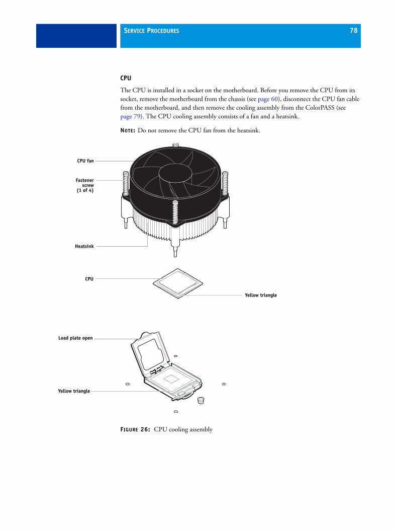
SERVICE PROCEDURES 78
CPU
The CPU is installed in a socket on the motherboard. Before you remove the CPU from its socket, remove the motherboard from the chassis (see page 60), disconnect the CPU fan cable from the motherboard, and then remove the cooling assembly from the ColorPASS (see page 79). The CPU cooling assembly consists of a fan and a heatsink.
NOTE: Do not remove the CPU fan from the heatsink.
FIGURE 26: CPU cooling assembly
Fastenerscrew
(1 of 4)
CPU fan
Heatsink
CPU
Yellow triangle
Load plate open
Yellow triangle

SERVICE PROCEDURES 79
If you remove the CPU from the motherboard in order to install it on a new motherboard, unpack the new motherboard and remove the protective plastic cover on the CPU socket. Transfer the protective cover to the CPU socket of the old motherboard to protect the circuitry. Follow standard ESD precautions while handling the motherboard and all components.
TO REMOVE THE COOLING ASSEMBLY
1 Shut down, and then open the ColorPASS (see page 51).
2 Remove the motherboard components.
3 Remove the power supply (see page 87).
4 Remove the motherboard from the chassis (see page 60).
Place the motherboard on a flat, anti-static surface.
5 Remove the CPU fan cable from motherboard.
6 Remove the CPU cooling assembly:
Be aware that both the cooling assembly and the CPU may be very hot. You may need to allow the components to cool before you attempt to remove them.
• Loosen the four screws that secure the cooling assembly to the motherboard. Partially loosen all the screws before loosening any one screw all the way.
• Lift the cooling assembly off the CPU socket and set it aside.
7 Lift the cooling assembly off the CPU socket and set it aside.
Be aware that the cooling assembly and the CPU may be very hot. You may need to let the components cool before attempting to remove them.
Loosen each screw to this position.
Screw (1 of 4)

SERVICE PROCEDURES 80
TO REMOVE AND REPLACE THE CPU
1 Unlock the CPU socket lever and raise it into the open position (flex the lever away from the retention post, and then raise it).
2 Open the load plate (see Figure 27 on page 80).
3 Grasp the CPU by its edges, lift it out of the socket, and then place the CPU in a safe place.
NOTE: If you remove the CPU from the motherboard to install it on a new motherboard, unpack the new motherboard and remove the protective plastic cover from the CPU socket. Transfer the protective cover to the CPU socket of the old motherboard to protect the circuitry.
4 Wipe the contact surface of the CPU (the smooth, gray side of the chip) with a clean, lint-free cloth to ensure proper contact with the new heatsink.
If you remove the CPU from the motherboard to install it on a new motherboard, make sure that you completely remove any thermal compound residue on the surface of the CPU and at the base of the heatsink. It may help to scrape all the residue off of the surface using the flat edge of something non-conductive.
5 Prepare the CPU socket by ensuring that:
• The socket lever is in the open position.
• The load plate is open.
6 Place the CPU in the socket.
The CPU and the socket are keyed to ensure correct installation. The notches on the edges of the CPU correspond with the two small posts inside the socket. Align the yellow triangle on the CPU with the yellow triangle on the socket. Do not force the CPU.
7 Close the load plate.
8 Lower the socket lever and place it in the locked position under the retention post.
FIGURE 27: Removing/replacing the CPU
Load plate open
CPU
Socket lever in the open positionSocket lever in
the locked positionYellow triangle
Yellow triangle

SERVICE PROCEDURES 81
TO REPLACE THE CPU COOLING ASSEMBLY
NOTE: Before you install the cooling assembly, completely remove any thermal compound residue on the surface of the CPU and the base of the heatsink, and then apply a fresh thermal compound square to the base of the heatsink. When installing the thermal compound square, make sure to remove the plastic backing on both sides of the square. Avoid creating any bubbles or wrinkles on the square. Bubbles and wrinkles reduce the heat-transfer efficiency of the cooling assembly.
1 Prepare the CPU cooling assembly for installation.
• Make sure that the motherboard is placed on a padded, static-free work surface.
• Apply a fresh thermal compound square, as described in the note above.
• Align the cooling assembly so that when it is installed, the fan cable easily reaches the CPU fan power connector FAN 1 on the motherboard.
2 Place the cooling assembly on the CPU.
• Make sure that the thermal pad on the underside of the heatsink is positioned on top of the CPU.
Be sure to remove any protective material that may be covering the surface of the thermal pad. Otherwise the CPU may overheat.
• Align the four screws with the four screw posts.
Tighten the screws. Partially tighten all the screws before tightening any one screw all the way.
3 Connect the CPU fan cable to the motherboard connector FAN 1.
If you are installing a new CPU, secure slack in the fan cable using a tie-wrap. The tie-wrap prevents the fan cable from interfering with the CPU fan. Also, make sure the connector on the cable is securely connected to the motherboard.
4 If you replaced the CPU with a new CPU, clear the CMOS as follows:
You must clear the CMOS after installing a new CPU to ensure compatibility between the new component and the previous settings stored in the BIOS. Make sure that the power cable is removed from the power outlet before clearing the CMOS.
• Remove the battery (see page 82).
• Wait two minutes to allow the motherboard electrical components to fully discharge.
• Reinstall the battery.
5 If you installed a new CPU and cleared the CMOS, make sure to reset the time and date in Setup (see Configuration and Setup, which is part of the user documentation set).
6 Reassemble the ColorPASS and verify its functionality (see page 103).

SERVICE PROCEDURES 82
Battery
The battery on the motherboard is located at BT1. To replace it, use a 3V manganese dioxide lithium coin cell battery (Sony CR2032 or equivalent).
There is danger of explosion if the battery is replaced with an incorrect type. Replace it only with the same type recommended by the manufacturer. Dispose of used batteries according to local regulations.
ACHTUNG: Es besteht Explosionsgefahr, wenn die Batterie durch eine Batterie falschen Typs ersetzt wird. Als Ersatz dürfen nur vom Hersteller empfohlene Batterien gleichen oder ähnlichen Typs verwendet werden. Verbrauchte Batterien müssen entsprechend den jeweiligen gesetzlichen Bestimmungen entsorgt werden.
ATTENTION: Il y a risque d’explosion si la pile est remplacée par un modèle qui ne convient pas. Remplacez-la uniquement par le modèle recommandé par le constructeur. Débarrassez-vous des piles usées conformément aux réglementations locales en vigueur.
ADVARSEL!: Litiumbatteri - Eksplosionsfare ved fejlagtig håndtering. Batteriet må kun udskiftes med et andet batteri af samme fabrikat og type. Brugte batterier skal bortskaffes i henhold til gældende regler.
VAROITUS: Paristo voi räjähtää, jos se on vaihdetaan väärän tyyppiseen paristoon. Vaihda paristo ainoastaan laitevalmistajan suosittelemaan tyyppiin. Hävitä käytetty paristo paikallisten määräysten mukaisesti.
ADVARSEL: Eksplosjonsfare ved feilaktig skifte av batteri. Benytt samme batteritype eller en tilsvarende type anbefalt av apparatfabrikanten. Brukte batterier kasseres i henhold til lokal lovgivning.
VARNING: Risk för explosion om batteriet byts ut mot en felaktig batterityp! Byt bara ut batteriet mot en batterityp som har godkänts av tillverkaren. Hantera använda batterier enligt lokal miljölagstiftning.
CUIDADO: Existe peligro de explosión si la batería se sustituye por una batería del tipo incorrecto. Sustituya la batería sólo por una batería del mismo tipo que recomienda el fabricante. Deseche las baterías usadas respetando la normativa local.
ATTENZIONE: Esiste pericolo di esplosione se la batteria viene sostituita con una di tipo non corretto. Sostituirla solamente con un tipo raccomandato dal produttore. Lo smaltimento delle batterie usate deve essere eseguito secondo le normative locali.
AVISO: Existe o perigo de explosão se a bateria for substituída por uma do tipo incorreto. Substitua somente por uma do tipo recomendado pelo fabricante. Descarte as baterias conforme as normas locais.
GEVAAR: Er bestaat ontploffingsgevaar indien de batterij door een verkeerd type wordt vervangen. Vervang de batterij uitsluitend door hetzelfde door de fabrikant aanbevolen type. Ruim gebruikte batterijen op volgens de plaatselijke voorschriften.
TO REPLACE THE BATTERY
1 Shut down, and then open the ColorPASS (see pages 48 and 51).
2 Locate the battery on the motherboard (see Figure 21 on page 61).
3 Carefully push the clip away from the battery until the socket ejects the battery.
FIGURE 28: Motherboard battery
Battery
Socket
Clip

SERVICE PROCEDURES 83
4 Slide the battery out of its socket.
5 Wait two minutes to allow the motherboard electrical components to fully discharge.
6 To insert a new battery, slide it into the socket so that the positive (+) side of the battery faces up.
7 Press the battery down into the socket until it snaps into place.
Make sure that the battery is securely installed in the socket.
8 Reassemble the system and verify its functionality (see page 103).
9 Configure the time and date in Setup (see Configuration and Setup, which is part of the user documentation set).
Failure to configure the time and date will cause the ColorPASS to hang when user software is being installed on the ColorPASS. (See page 127.)
Clearing the CMOS
Clear the CMOS after installing a new motherboard, CPU, DIMM, or DVD drive to ensure compatibility between the new component and previous settings stored in the BIOS.
TO CLEAR THE CMOS
1 Shut down, and then open the ColorPASS (see pages page 48 and page 51).
Make sure to remove the copier interface cable from the power outlet before opening the ColorPASS and clearing the CMOS.
2 Remove the battery (see page 82).
3 Wait two minutes to allow the motherboard electrical components to fully discharge.
4 Reinstall the battery (see page 82).
5 Reassemble the ColorPASS and verify its functionality (see page 103).
6 Reset the time and date in Setup (see Configuration and Setup, which is part of the user documentation set).
Failure to configure the time and date will cause the ColorPASS to hang when user software is being installed on the ColorPASS (see page 127).
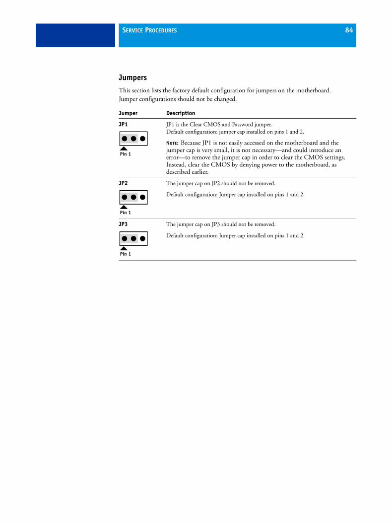
SERVICE PROCEDURES 84
Jumpers
This section lists the factory default configuration for jumpers on the motherboard. Jumper configurations should not be changed.
Jumper Description
JP1 JP1 is the Clear CMOS and Password jumper.Default configuration: jumper cap installed on pins 1 and 2.
NOTE: Because JP1 is not easily accessed on the motherboard and the jumper cap is very small, it is not necessary—and could introduce an error—to remove the jumper cap in order to clear the CMOS settings. Instead, clear the CMOS by denying power to the motherboard, as described earlier.
JP2 The jumper cap on JP2 should not be removed.
Default configuration: Jumper cap installed on pins 1 and 2.
JP3 The jumper cap on JP3 should not be removed.
Default configuration: Jumper cap installed on pins 1 and 2.
Pin 1
Pin 1
Pin 1
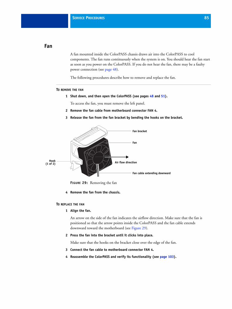
SERVICE PROCEDURES 85
FanA fan mounted inside the ColorPASS chassis draws air into the ColorPASS to cool components. The fan runs continuously when the system is on. You should hear the fan start as soon as you power on the ColorPASS. If you do not hear the fan, there may be a faulty power connection (see page 48).
The following procedures describe how to remove and replace the fan.
TO REMOVE THE FAN
1 Shut down, and then open the ColorPASS (see pages 48 and 51).
To access the fan, you must remove the left panel.
2 Remove the fan cable from motherboard connector FAN 4.
3 Release the fan from the fan bracket by bending the hooks on the bracket.
FIGURE 29: Removing the fan
4 Remove the fan from the chassis.
TO REPLACE THE FAN
1 Align the fan.
An arrow on the side of the fan indicates the airflow direction. Make sure that the fan is positioned so that the arrow points inside the ColorPASS and the fan cable extends downward toward the motherboard (see Figure 29).
2 Press the fan into the bracket until it clicks into place.
Make sure that the hooks on the bracket close over the edge of the fan.
3 Connect the fan cable to motherboard connector FAN 4.
4 Reassemble the ColorPASS and verify its functionality (see page 103).
Hook(1 of 2)
Fan
Fan bracket
Air flow direction
Fan cable extending downward
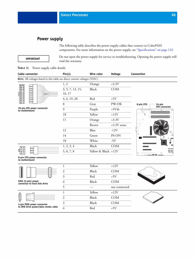
SERVICE PROCEDURES 86
Power supplyThe following table describes the power supply cables that connect to ColorPASS components. For more information on the power supply, see “Specifications” on page 132.
Do not open the power supply for service or troubleshooting. Opening the power supply will void the warranty.
TABLE 1: Power supply cable details
Cable connector Pin(s) Wire color Voltage Connection
NOTE: All voltages listed in this table are direct current voltages (VDC).
1, 2 Orange +3.3V
3, 5, 7, 13, 15, 16, 17
Black COM
4, 6, 19, 20 Red +5V
8 Gray PW-OK
9 Purple +5Vsb
10 Yellow +12V
11 Orange +3.3V
Brown +3.3V sense
12 Blue -12V
14 Green PS-ON
18 White -5V
1, 2, 3, 4 Black COM
5, 6, 7, 8 Yellow & Black +12V
1 Yellow +12V
2 Black COM
3 Red +5V
4 Black COM
5 — not connected
1 Yellow +12V
2 Black COM
3 Black COM
4 Red +5V
10
9
8
7
6
5
4
3
2
1
20
19
18
17
16
15
14
13
12
11
20-pin ATX power connectorto motherboard
24-pin ATX connector
8-pin CPU
4
3
2
1
8
7
6
5
8-pin CPU power connectorto motherboard
SATA (5-pin) power connector to hard disk drive
4-pin PATA power connector to DVD drive power/data combo cable

SERVICE PROCEDURES 87
TO REMOVE THE POWER SUPPLY
1 Shut down, and then open the ColorPASS (see pages 48 and 51).
To access the power supply, you must remove the left panel.
2 Remove the power cable from the hard disk drive.
3 Remove the power and data combination cable from the DVD drive.
4 Remove the 20-pin motherboard power cable from motherboard connector PW2.
5 Remove the 8-pin CPU power cable from motherboard connector PW1.
6 Remove the reusable tie-wrap securing the power cables to the chassis support beam.
Do not cut the tie-wrap. Squeeze the tab to unlock it, and then open it completely and remove it. You will reattach the tie-wrap later when you replace the power supply.
7 Remove the ferrites that are installed around the hard disk drive power cables.
Carefully pry open the latches on the sides of the ferrites and remove the ferrites from the cables. Set the ferrites aside so that you can replace them later.
8 Remove four of the five screws that attach the power supply to the back of the chassis(see Figure 30 on page 88).
9 While supporting the power supply, remove the fifth screw.
Set the screws aside so that you can replace them later.
10 Lift the power supply out of the chassis.
Carefully gather the power supply cables as you remove the power supply.
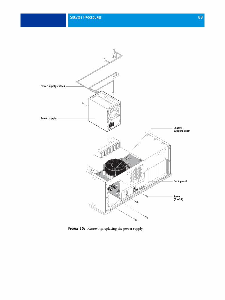
SERVICE PROCEDURES 88
FIGURE 30: Removing/replacing the power supply
Screw(1 of 4)
Power supply
Back panel
Power supply cables
Chassissupport beam

SERVICE PROCEDURES 89
TO REPLACE THE POWER SUPPLY
1 Support the power supply inside the chassis and align the mounting holes.
2 Attach the power supply to the chassis with the five screws that you removed earlier (see Figure 30 on page 88).
If you are installing a new power supply, make sure to use the screws that came with it to attach the new power supply to the chassis.
3 Connect the 8-pin CPU power cable to motherboard connector PW1 (for connector locations, see Figure 21 on page 61).
4 Connect the 20-pin motherboard power cable to motherboard connector PW2.
5 Connect the power and data combination cable to the DVD drive.
6 Install the ferrite around the hard disk drive power cable.
Use the ferrite that you removed earlier. Place the ferrite around the cable near the connector and snap the edges of the ferrite closed.
7 Connect the power cable to the hard disk drive.
Connect the thin, black SATA power cable connector to the hard disk drive. Do not connect the white, 4-pin power cable connector. Connecting both types of power cableswill damage the hard disk drive.
8 Locate the reusable tie-wrap that you removed earlier and use it to attach the loose section of the power cable to the chassis support beam (see Figure 30 on page 88).
Gather the cable against the support beam with the tie-wrap, and then thread the tie-wrap to secure the cable.
9 Reassemble the ColorPASS and verify its functionality (see page 103).

SERVICE PROCEDURES 90
Hard disk driveThe factory-installed hard disk drive (HDD) is formatted and loaded with system software, network drivers, and printer fonts. The hard disk drive is also used to store spooled print jobs. Available space on the hard disk drive is displayed on the Info screen of the copier touch panel and in Command WorkStation.
If you replace the hard disk drive with a new one, you must install system software as described on page 104. (Spare hard disk drives are not shipped with preinstalled system software.)
Do not replace the hard disk drive and the motherboard at the same time. Doing so in the wrong order, without updating the system (see page 64), will cause the system to malfunction.
It is unlikely that both the hard disk drive and the motherboard are defective. Avoid replacing both to solve one problem. If troubleshooting strategies (such as checking cables and connections; see pages 113 and 114) do not solve the problem, and you suspect either the hard disk drive or the motherboard is at fault, use the following order to troubleshoot: replace the hard disk drive, install system software, and then check to see if the problem persists. If it does, perform other procedures, such as replacing the motherboard (see page 64).
Proper handling
Improper handling can damage a hard disk drive. Handle the hard disk drive with extreme care.
• Use proper ESD practices when grounding yourself and the ColorPASS.
• Keep magnets and magnetic-sensitive objects away from the hard disk drive.
• Do not remove the screws on top of the hard disk drive. Loosening these screws voidsthe warranty.
• Never drop, jar, bump, or put excessive pressure on the hard disk drive.
• Handle the hard disk drive by its sides and avoid touching the printed circuit board.
• Allow the hard disk drive to reach room temperature before installation.
Hard disk drive problems may be caused by the following:
• Loose or faulty connections
• Faulty data or power cable
• Faulty hard disk drive
Make sure that you attach an ESD grounding wrist strap and follow standard ESD precautions before handling ColorPASS components.
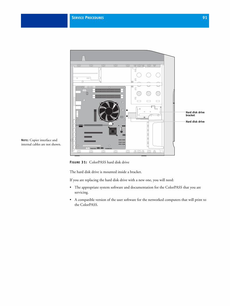
SERVICE PROCEDURES 91
FIGURE 31: ColorPASS hard disk drive
The hard disk drive is mounted inside a bracket.
If you are replacing the hard disk drive with a new one, you will need:
• The appropriate system software and documentation for the ColorPASS that you are servicing.
• A compatible version of the user software for the networked computers that will print to the ColorPASS.
NOTE: Copier interface and internal cables are not shown.
Hard disk drive
Hard disk drive bracket
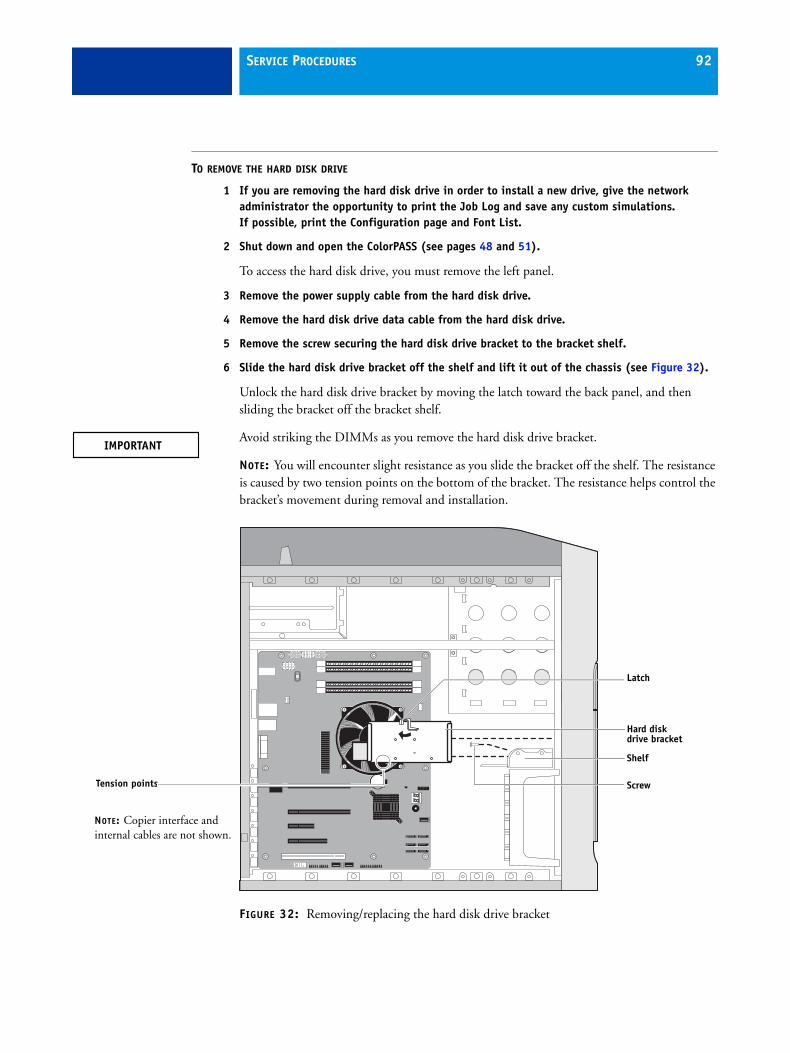
SERVICE PROCEDURES 92
TO REMOVE THE HARD DISK DRIVE
1 If you are removing the hard disk drive in order to install a new drive, give the network administrator the opportunity to print the Job Log and save any custom simulations. If possible, print the Configuration page and Font List.
2 Shut down and open the ColorPASS (see pages 48 and 51).
To access the hard disk drive, you must remove the left panel.
3 Remove the power supply cable from the hard disk drive.
4 Remove the hard disk drive data cable from the hard disk drive.
5 Remove the screw securing the hard disk drive bracket to the bracket shelf.
6 Slide the hard disk drive bracket off the shelf and lift it out of the chassis (see Figure 32).
Unlock the hard disk drive bracket by moving the latch toward the back panel, and then sliding the bracket off the bracket shelf.
Avoid striking the DIMMs as you remove the hard disk drive bracket.
NOTE: You will encounter slight resistance as you slide the bracket off the shelf. The resistance is caused by two tension points on the bottom of the bracket. The resistance helps control the bracket’s movement during removal and installation.
FIGURE 32: Removing/replacing the hard disk drive bracket
Latch
Hard disk drive bracket
Tension points
Shelf
Screw
NOTE: Copier interface and internal cables are not shown.
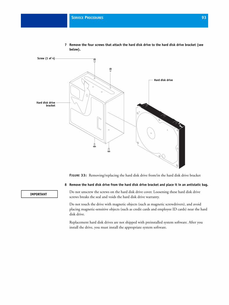
SERVICE PROCEDURES 93
7 Remove the four screws that attach the hard disk drive to the hard disk drive bracket (see below).
FIGURE 33: Removing/replacing the hard disk drive from/in the hard disk drive bracket
8 Remove the hard disk drive from the hard disk drive bracket and place it in an antistatic bag.
Do not unscrew the screws on the hard disk drive cover. Loosening these hard disk drive screws breaks the seal and voids the hard disk drive warranty.
Do not touch the drive with magnetic objects (such as magnetic screwdrivers), and avoid placing magnetic-sensitive objects (such as credit cards and employee ID cards) near the hard disk drive.
Replacement hard disk drives are not shipped with preinstalled system software. After you install the drive, you must install the appropriate system software.
Hard disk drivebracket
Hard disk drive
Screw (1 of 4)

SERVICE PROCEDURES 94
TO REPLACE THE HARD DISK DRIVE
Do not install a new hard disk drive and a new motherboard at the same time. If you suspect that the ColorPASS needs a new hard disk drive and a new motherboard, first install the new hard disk drive and install system software, then install a new motherboard and transfer options (see pages 64 and 71).
1 If you are installing a new hard disk drive, unpack the drive.
Do not drop, jar, or bump the hard disk drive. Do not touch the hard disk drive with magnetic objects or place magnetic-sensitive objects s near the hard disk drive.
2 Position the hard disk drive inside the hard disk drive bracket and align the front-most mounting holes on the hard disk drive with the four holes in the bracket (see Figure 32 on page 92).
When correctly installed, the hard disk drive extends about an inch past the rear of the bracket.
3 Replace the four screws that you removed earlier to attach the hard disk drive to the bracket.
4 Slide the bracket all the way onto the shelf and lock it by moving the latch toward the front panel.
Avoid striking the DIMMs as you replace the hard disk drive bracket.
NOTE: You will encounter slight resistance as you slide the bracket onto the shelf. The resistance is caused by two tension points on the bottom of the bracket. The resistance helps control the bracket’s movement during removal and installation.
5 Secure the hard disk drive bracket to the hard disk drive shelf using the screw that you removed earlier.
6 Connect the other end of the hard disk drive data cable to the appropriate SATA connector on the motherboard (see Figure 21 on page 61).
7 Connect the power cable to the hard disk drive.
Connect the thin, black SATA power cable connector to the hard disk drive. Do not connect the white, 4-pin power cable connector. Connecting both types of power cables will damage the hard disk drive.
8 Reassemble the ColorPASS (see page 103).
(Continued on next page)

SERVICE PROCEDURES 95
9 If you replaced the hard disk drive with a new hard disk drive, install system software (see page 104).
Troubleshooting tips:
• Following system software installation, if the ColorPASS boots up much slower than usual, clear the CMOS as follows:
– Make sure that the power cable is removed from the power outlet, and then remove the battery (see page 82).
– Wait two minutes to allow the motherboard electrical components to fully discharge.
– Reinstall the battery.
– After reassembling the system, reset the time and date in Setup (see Configuration and Setup, which is part of the user documentation set).
• If a startup error displays on the Control Panel when you power on the ColorPASS, check the connections.
10 Verify functionality (see page 103).

SERVICE PROCEDURES 96
Switch bank assemblyThe switch bank assembly attaches to the component sled. The switch bank assembly includes the following components:
• DVD drive
• Power button and cable
• Reset button and cable
• Speaker and cable
• Front USB ports and cables
NOTE: For more information about servicing the DVD drive, see page 100.
FIGURE 34: component sled with switch bank assembly
Switch bank assembly with DVD drive
Component sled
Guide latch(1 of 2)
NOTE: Copier interface and internal cables are not shown.

SERVICE PROCEDURES 97
TO REMOVE THE SWITCH BANK ASSEMBLY
1 Shut down, and then open the ColorPASS (see pages 48 and 51).
To remove the switch bank assembly, you must remove the left, right, and front panels.
2 Disconnect the following cables:
• Power and data combination cable from the back of the DVD drive
• Power and reset button cables from motherboard connector SSI CONN
• Speaker cable from motherboard connector JP5
• Front panel USB port cables from motherboard connectors USB2 and USB4
3 Remove the ferrite that is installed around the front panel USB port cables near the motherboard.
Carefully pry open the latch on the side of the ferrite and remove the ferrite from the cables. Set the ferrite aside so that you can replace it later.
4 Unharness the cables from the cable clamp(s) and tie-wraps inside the chassis.
5 Remove the component sled from the chassis (see Figure 34 on page 96).
Press the guide latches on the sides of the component sled and carefully pull the sled out of its slot in the front of the chassis.
FIGURE 35: Removing/replacing the component sled from the chassis
NOTE: Be careful not to damage the EMI gasket around the slot in the chassis. Guide the cables out of the chassis as you remove the component sled to prevent them from catching or tangling on internal parts.
Guide latch(1 of 2)
Component sled
Switch bank assembly
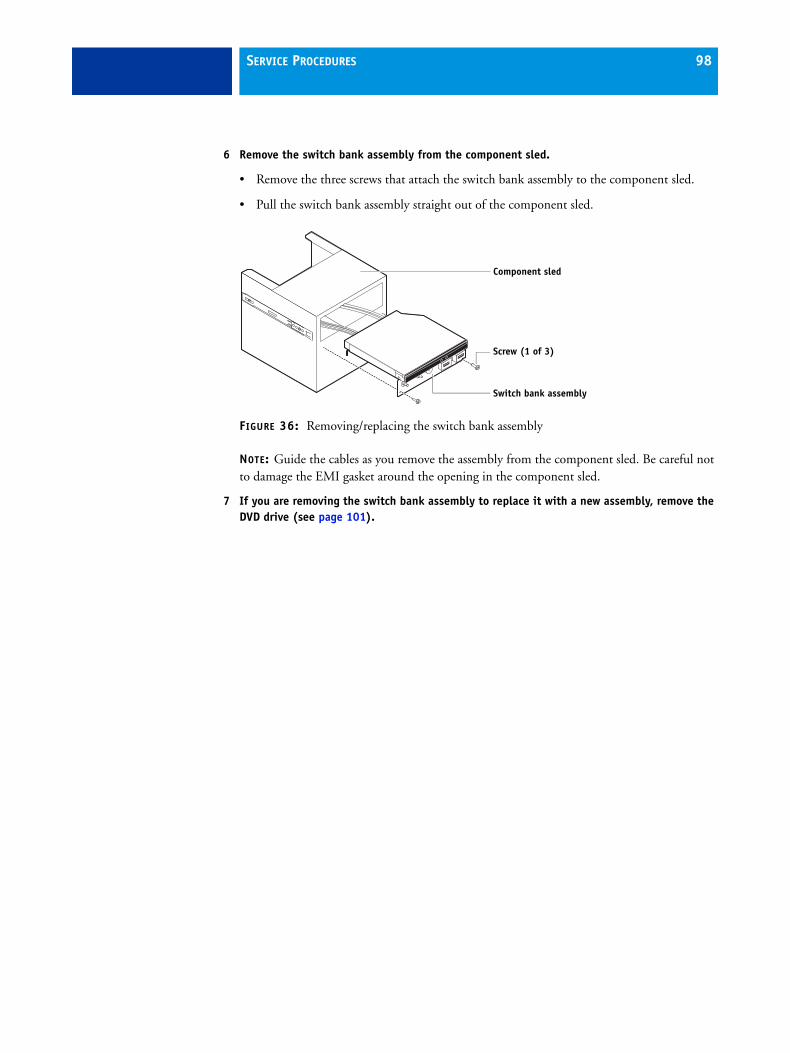
SERVICE PROCEDURES 98
6 Remove the switch bank assembly from the component sled.
• Remove the three screws that attach the switch bank assembly to the component sled.
• Pull the switch bank assembly straight out of the component sled.
FIGURE 36: Removing/replacing the switch bank assembly
NOTE: Guide the cables as you remove the assembly from the component sled. Be careful not to damage the EMI gasket around the opening in the component sled.
7 If you are removing the switch bank assembly to replace it with a new assembly, remove the DVD drive (see page 101).
Component sled
Switch bank assembly
Screw (1 of 3)
SERVICE PROCEDURES 99
TO REPLACE THE SWITCH BANK ASSEMBLY
1 If it is not already attached, attach the DVD drive to the switch bank assembly (see page 102).
2 Install the switch bank assembly in the component sled (see Figure 36).
NOTE: If you are replacing the switch bank assembly with a new one, discard the cable extensions that may be provided with the new switch bank assembly.
• Starting with the cables, insert the switch bank assembly through the opening in the front of the component sled. Be sure to fold the EMI gasket under and through the opening when inserting the assembly.
• Replace the three screws that secure the switch bank assembly to the component sled.
3 Install the component sled in the chassis (see Figure 35).
• Route the cables of the switch bank assembly in through the chassis so that the cables are within reach of their connectors on the motherboard.
• Slide the sled into the front of the chassis until the guide latches click into place.
NOTE: Be careful not to damage the EMI gasket around the slot in the chassis when installing the component sled.
4 Connect the following cables (see Figure 21 on page 61 for the location of connectors on the motherboard):
• Power and data combination cable to the back of the DVD drive
• DVD data cable to motherboard connector SATA 0
• Power button cable to motherboard connector SSI CONN, pins 11 nd 13
Make sure that the small triangle on the cable connector is aligned with pin 13 on SSI CONN.
• Reset button cable to motherboard connector SSI CONN, pins 15 and 17
Make sure that the small triangle on the cable connector is aligned with pin 17 on SSI CONN.
• Speaker cable to motherboard connector JP5
Make sure that the small triangle on the cable connector is aligned with pin 1 on JP5.
• Front panel USB port cables to motherboard connectors USB2 and USB4
5 Install the ferrite around the two front USB port cables near the motherboard.
Use the ferrite that you removed earlier. Place the ferrite around both cables in between the two preinstalled tie-wraps, and snap the edges of the ferrite closed.
6 Secure the cables with the cable clamp(s) inside the chassis.
7 Reassemble the ColorPASS and verify its functionality (see page 103).

SERVICE PROCEDURES 100
DVD driveThe DVD drive is attached to the switch bank assembly. The DVD drive is used to install system software onto the hard disk drive and archive data onto writable media.
FIGURE 37: ColorPASS DVD drive
DVD drive
Eject button

SERVICE PROCEDURES 101
TO REMOVE THE DVD DRIVE
1 Shut down, and then open the ColorPASS (see pages 48 and 51).
To remove the DVD drive, you must remove the left, right, and front panels, the component sled, and the switch bank assembly.
2 Remove the power and data combination cable from the back of the DVD drive.
3 Remove the component sled from the chassis, and then remove the switch bank assembly from the component sled (see page 97).
4 Remove the four screws that secure the DVD drive to the switch bank assembly.
Set aside the screws so that you can replace them later.
NOTE: On some systems, a small metal post in the switch bank assembly is used in place of one of the screws.
5 Remove the DVD drive from the switch bank assembly.
FIGURE 38: Removing/replacing the DVD drive
Component sled
Switch bank assembly
Screw (1 of 3)
Switch bank assembly
Screw(1 of 4)
DVD drive
NOTE: Some switch bank assemblies have a metal post in this location that is used in place of the screw.
SERVICE PROCEDURES 102
TO REPLACE THE DVD DRIVE
1 Install the DVD drive in the switch bank assembly.
2 Install the switch bank assembly in the component sled, and then install the component sled in the chassis (see page 99).
3 Attach the power and data combination cable to the back of the DVD drive.
Make sure that the other end of the data cable is connected to motherboard connector SATA 0.
4 If you replaced the DVD drive with a new DVD drive, clear the CMOS as follows:
You need to clear the CMOS after installing a new DVD drive to ensure compatibility between the new component and the previous settings stored in the BIOS. Make sure the power cable is removed from the power outlet before clearing the CMOS.
• Remove the battery (see page 82).
• Wait two minutes to allow the motherboard electrical components to fully discharge.
• Reinstall the battery.
5 If you installed a new DVD drive and cleared the CMOS, make sure to reset the time and date in Setup (see Configuration and Setup, which is part of the user documentation set).
6 Reassemble the ColorPASS and verify its functionality (see page 103).

SERVICE PROCEDURES 103
Restoring and verifying functionality after serviceBefore you leave the customer site, make sure that you complete the following steps. If you cannot complete a step, determine the reason and correct the problem before continuing. For more information, see Troubleshooting on page 111.
TO REASSEMBLE THE COLORPASS AND VERIFY FUNCTIONALITY
1 Reseat all boards, cables, connectors, and other parts loosened or removed during service.
When routing cables inside the ColorPASS, make sure that:
• Covers are securely installed after routing cables
• Cable routing does not interfere with the operation of internal components nor interfere with removing or replacing components
• Cables are not tangled nor looped around internal circuit boards or components (such as capacitors and resistors)
• Cables do not lie on or against any internal heating element
• Cables do not interfere with opening or closing ColorPASS panels
• Cable slack is secured with a tie-wrap
2 Restore the ColorPASS to the upright position.
3 Replace any panels that you removed earlier, as described on page 51.
4 If you replaced the motherboard, make sure that the new motherboard solves the problem that you are troubleshooting, and then transfer options to the new motherboard (see page 71).
5 If the ColorPASS is to be mounted on the optional furniture with the optional monitor, see the reassembly instructions on page 134.
6 Connect the power cable to the ColorPASS (see page 28).
7 If you cleared the CMOS during service, reset the ColorPASS time and date in Setup.
8 Connect the ColorPASS to the copier (see page 28).
9 Print the Test Page and Configuration page.
• If the ColorPASS does not start up, refer to the startup problems listed on page 122.
• If pages do not print, verify that the interface cables are properly connected (see printing problems on page 129).
• If image quality is poor, test the copier (see the service documentation that accompanies the copier).
10 Connect to the network (see page 28).
11 Ask the network administrator to download a test job over the network.
If the job does not print, or has poor image quality, see printing problems and the Troubleshooting sections of the user documentation.

SYSTEM AND USER SOFTWARE 104
SYSTEM AND USER SOFTWARE
This chapter describes how to install system and user software on the ColorPASS hard disk drive.
OverviewThe ColorPASS ships with pre-installed system software on the hard disk drive. If you need to reinstall system software in the future, use the System Software DVDs included in the media pack.
NOTE: In order to install system software on the ColorPASS, a monitor must be connected.
Before you install system softwareWhen installing software, keep in mind the following:
• Jobs: All jobs in all print queues and all jobs archived locally on the ColorPASS hard disk drive are deleted when you install system software. To save jobs, ask the network administrator to archive them to a CD or location on the network, so that the jobs can be imported back into the ColorPASS queue after system software installation. For more information, see Command WorkStation Help.
NOTE: Notify the network administrator at the customer site that some archived jobs may no longer print after you install an updated version of system software.
• Job Log: The list of jobs in the Job Log and any jobs in the queues are deleted when you install system software. The network administrator can use Command WorkStation to save a current list of jobs (not the actual jobs) from the Job Log.
• Fonts: All fonts on the hard disk drive are deleted when you install system software. Resident fonts are reinstalled when you reinstall system software. Any customer-supplied fonts must be reinstalled by the network administrator using Command WorkStation.
To determine which additional fonts were downloaded to the ColorPASS, print the Font List before you install the system software and again after you complete the system software installation. Any fonts not listed after installation will need to be reinstalled. For more information, see Command WorkStation Help.
• Configuration: The existing Setup configuration is lost when you install system software. Make sure to print a Configuration page before you install system software so that you can reconfigure the settings in Setup (see page 39).
• User documentation: All user documentation files, which may be resident on the ColorPASS, are deleted when you install system software. If user documentation is resident on the ColorPASS, remind the site administrator to reinstall the documentation files after you finish installing system software.

SYSTEM AND USER SOFTWARE 105
• Custom simulation and output profiles: Custom simulation and custom output profiles saved on the hard disk drive are deleted when you install system software. Ask the site administrator to save a copy of any custom profiles to a CD or network location before you install system software. For more information, see Color Printing, Fiery Color Reference, and Workflow Examples, which are part of the user documentation set.
• Monitor profiles: Monitor profiles saved to the hard disk drive are deleted when you install system software. Monitor profiles for the ColorPASS monitor are automatically reinstalled when you reinstall Command WorkStation on the system.
• System software updates: All updates to system software (Windows OS and Fiery System Software) which may be available for the ColorPASS and installed from any source (for example, System Updates (see page 110), and any patches provided on CD or downloaded by the customer) are deleted when you install system software.
NOTE: Microsoft Windows system updates should be obtained from Microsoft directly. Because such updates are available directly from Microsoft, EFI does not maintain or provide them via the System Updates feature.
• Compatibility: When upgrading the software on the ColorPASS, make sure that the latest user software is installed on all computers that print to the ColorPASS. Using incompatible versions of the software on the ColorPASS and the user software on client computers may result in system problems.
SYSTEM AND USER SOFTWARE 106
Backing up the system configurationIf you back up the system configuration, you can restore it after installing, reinstalling, and upgrading system software. When you back up the system configuration, you save a configuration file that includes one or more of the following:
• Fiery Settings
• Color Settings
• Preflight Templates
• FreeForm/VDP resources
• Server Presets
• Fonts
• Job Log
• Virtual Printers
If you cannot create a configuration file, ask the network administrator to archive custom color profiles, preflight templates, FreeForm masters, customer-installed fonts, and the Job Log to removable media or a network location.
NOTE: Paper Catalog is not supported because the copier interface controls the stock library settings.
TO SAVE THE SYSTEM CONFIGURATION BEFORE SYSTEM SOFTWARE INSTALLATION
1 Ask the network administrator to print the Job Log, Configuration page, and Font List (if possible).
For more information, see “ColorPASS copier touch panel Functions menu” on page 36.
2 On the screen, right-click FieryBar. In the shortcut menu, choose WebTools or Command WorkStation.
3 In WebTools or Command WorkStation, click the Configure tab > Launch Configure.
4 Log on with Administrator privileges and click OK.
The default Administrator password is Fiery.1 (case-sensitive), but the network administrator may have changed the password.
5 On the left side, choose Server > Backup/Restore, and then click the Backup button.
6 In the Backup dialog box, select the settings you want to back up, and then click Next.
7 Enter a file name and location, and then click Next.
8 Click Finish.

SYSTEM AND USER SOFTWARE 107
Restoring the system configurationYou can restore the configuration of the ColorPASS to its previous state using a configuration file. For more information about a configuration file, see “To save the system configuration before system software installation” on page 106.
If you could not save a configuration file, you must configure Setup. After you exit Setup and the ColorPASS reboots, ask the network administrator to restore any archived settings and files. For more information, see Configuration and Setup, which is part of the user documentation set.
TO RESTORE THE SYSTEM CONFIGURATION AFTER SYSTEM SOFTWARE INSTALLATION
1 On the screen, right-click FieryBar. In the shortcut menu, click WebTools or Command WorkStation.
2 Right-click FieryBar. In the shortcut menu, click WebTools or Command WorkStation.
3 In WebTools or Command WorkStation, click the Configure tab.
4 Click the Launch Configure button.
5 Enter the Administrator password for the ColorPASS. Click OK.
6 The default Administrator password is Fiery.1. However, the network administrator can change the password.
7 On the left side, choose Server > Backup/Restore.
8 Click the Restore button.
9 Browse to the configuration file. Click Next.
For more information, see “To save the system configuration before system software installation” on page 106.
10 In the Restore dialog box, select settings to restore. Click Next.
11 Click Finish.
Installing system softwareSystem software is provided on the following media:
• DVD1: System software (Fiery)
• DVD2: Windows 7 Pro FES x64
• DVD3: Windows 7 Pro FES x64
• DVD4: User software (Drivers and Utilities)

SYSTEM AND USER SOFTWARE 108
The System Software DVDs include the system software, fonts, and user software. Install the system software when you do the following:
• Replace the hard disk drive.
• Upgrade to a more recent version of the system software.
• Change languages.
Software installation takes approximately one hour (not including the time required to configure Setup).
TO INSTALL OR UPGRADE SYSTEM AND USER SOFTWARE
1 Before you proceed, do the following:
• On the ColorPASS, remove all dongles and devices, except the keyboard and mouse.
If you do not, installation will fail.
• Ask the network administrator to print the Job Log, Configuration page, and Font List, and to archive and customer-installed fonts and FreeForm masters (if possible).
2 If you are installing system software, back up the system configuration (if possible).
For more information, see “Backing up the system configuration” on page 106.
3 Insert System Software DVD 1 into the DVD drive, and then reboot the ColorPASS.
Wait while the system boots from the DVD.
4 Select a language from the drop-down list, and click the arrow button to continue.
5 When the “This installation will erase all data on the hard disk drive(s). Continue?” message appears, click Continue.
6 When the “Install optional software? The following software package is optional: Adobe Acrobat/Enfocus Pit-Stop” message appears, click Install. Wait for files to be copied to the ColorPASS from System Software DVD 1.
Time required: approximately three minutes.
The disc ejects when this step is complete.
7 At the prompt for each DVD, insert System Software DVD 2, System Software DVD 3, and then System Software 4 into the DVD drive. Wait for files to be copied to the ColorPASS.
Time required: approximately eight minutes.
The disc ejects when this step is complete.
8 When prompted, insert the User Software DVD into the DVD drive. Wait for files to be copied to the ColorPASS.
Time required: approximately 12 minutes.
The disc ejects when this step is complete.
SYSTEM AND USER SOFTWARE 109
9 When the “Insert Adobe/ Acrobat/ Enfocus Pitstop” message displays, insert the Acrobat/PitStop DVD and follow the on-screen prompts.
Time required: approximately 20 minutes.
The disc ejects once files are copied.
10 Wait while files are installed on the ColorPASS.
Time required: approximately 40 minutes.
11 When prompted during the Acrobat installation, confirm that no other software is running and a location for the files to be installed.
12 At the Admin login, enter the password, and then press Enter. Wait for Command WorkStation to start and for FieryBar to indicate that the ColorPASS is Idle.
Fiery.1. is the default password and is case-sensitive.
13 Install any required software patches:
For more information, see “Installing software patches” on page 110.
14 If you were installing, but not upgrading, system software, restore the system configuration (if possible):
For more information, see “Restoring the system configuration” on page 107.
15 Before you leave the customer site, remind the network administrator to do the following:
• Import archived jobs.
Please note that some archived jobs may not print.
• Register Adobe Acrobat the first time you use it.
• Reinstall the following:
– Fonts
– User documentation
– Custom simulations
This upgrade may not be compatible with old user software.
System software installation error messagesIf an error message displays when you install or upgrade system software, do the following:
• If prompted, save the log.
• If you are not prompted to save the log, record the error message.
If you cannot correct the error, contact your authorized service/support center. A log or error message may help to solve the problem. Provide as much specific information as possible.

SYSTEM AND USER SOFTWARE 110
Installing software patchesAs part of reinstalling system software, you must reinstall software patches. For a list of patches that were installed on the ColorPASS, see the Configuration page that you printed before reinstalling. You may also need to reinstall software patches as part of upgrading system software.
If you upgraded system software, do not assume that the software patches listed on the Configuration page are required for the upgrade. You must contact your authorized service/support center for a list of required software patches. If you install a software patch that is not required for an upgrade, the system may be corrupted.
After you know which software patches are required for your system, you can download them from System Updates or Configure.
TO DOWNLOAD SOFTWARE PATCHES (SYSTEM UPDATES)
1 From the Windows Start menu, click All Programs > Fiery > System Updates.
2 Click Check Now.
TO DOWNLOAD SOFTWARE PATCHES (CONFIGURE)
1 Right-click FieryBar. In the shortcut menu, click WebTools.
2 On the WebTools home page, click the Configure tab.
3 On the Configure tab, click Check for Product Updates.
System updatesAdvise the network administrator that the System Updates feature available through the Start menu allows customers to schedule and accept installation of certain ColorPASS software updates from a secure site on the Internet. By default, the feature is configured to display a notification on the monitor that software updates are available for the ColorPASS. You can also check for system updates by choosing Start > All Programs > Fiery > System Updates, and then clicking Check Now. Depending on how it is configured, System Updates operates manually or automatically. For more information about how to schedule System Updates, see Configuration and Setup, which is part of the user documentation set.
You can obtain updates for Windows 7 Professional FES x64 from Microsoft directly. Since these updates are available from Microsoft directly, EFI does not provide them by means of System Updates.

TROUBLESHOOTING 111
TROUBLESHOOTING
This chapter identifies the source of common problems that may occur with the ColorPASS and suggests ways of correcting them.
Troubleshooting processThe ColorPASS is a server for copieres, and is generally part of a configuration like the one shown in the following figure. Problems may occur in one of three areas:
• Inside the ColorPASS
• In the interface between the ColorPASS and the copier
• In the interface between the ColorPASS and the workstations or computers to which it is connected
FIGURE 39: Troubleshooting the system
This chapter does not attempt to provide troubleshooting information for attached computers such as PCs or Mac OS computers, copiers, or extensive networks. Refer problems in these areas to the appropriate service departments and network administrators.
When performing the service procedures described in this chapter, follow the precautions listed in “Precautions” on page 14.
ColorPASS
copier
Networked computers or workstations

TROUBLESHOOTING 112
Preliminary on-site checkoutMost problems with the ColorPASS are caused by loose board or cable connections. This section describes the quick checks that you can do to locate and fix obvious problems. It describes how to eliminate any problems with external connections to the back of the ColorPASS, and then addresses checking internal board and cable connections. Check external and internal connections before replacing any components.
NOTE: Verify that the network is functioning, no unauthorized software or hardware is installed on the ColorPASS, and no problems have occurred with a particular print job or application. The on-site administrator can help you verify these issues.
For problems that persist after you check the external and internal connections, this section provides a comprehensive list of internal and external checks that may help you fix the problem.
This section includes the following:
• “Checking external connections” on page 113
Describes the quick checks that you can do to make sure that the problem is not caused by a loose connection at the back of the ColorPASS.
• “Checking internal components” on page 114
Describes the quick checks that you can do to make sure that the problem is not caused by a loose board or cable connection inside the ColorPASS.
• “Inspecting the system” on page 115
Provides a more comprehensive checklist that you can use to check the ColorPASS internally and externally. If your initial checks fail, complete this checklist before concluding that you need to replace a cable or component.
To troubleshoot problems that present specific symptoms, see “ColorPASS error messages and condition” on page 122. Locate symptoms listed in the table to help you determine possible causes and steps to remedy them.
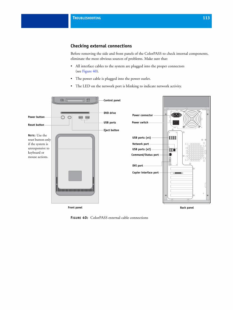
TROUBLESHOOTING 113
Checking external connections
Before removing the side and front panels of the ColorPASS to check internal components, eliminate the most obvious sources of problems. Make sure that:
• All interface cables to the system are plugged into the proper connectors(see Figure 40).
• The power cable is plugged into the power outlet.
• The LED on the network port is blinking to indicate network activity.
FIGURE 40: ColorPASS external cable connections
Front panel
USB ports
Power button
Control panel
DVD drive
Reset button
NOTE: Use the reset button only if the system is unresponsive to keyboard or mouse actions.
Eject button
Back panel
Power connector
Network port
USB ports (x4)
USB ports (x2)
Copier interface port
Power switch
Command/Status port
DVI port

TROUBLESHOOTING 114
Checking internal components
To check the internal components, you must remove the side and front panels of the ColorPASS.
Before you remove the ColorPASS panels, be aware of the safety precautions that you should take when handling the ColorPASS. Use standard ESD precautions when handling printed circuit boards and electronic components. To review the safety precautions, see “Precautions” on page 14.
See the disassembly procedures on page 48 and the reassembly procedures on page 103.
TO CHECK INTERNAL COMPONENTS
1 Shut down, and then open the ColorPASS.
2 Before you touch any components inside the ColorPASS, attach a grounding strap to your wrist and discharge any static electricity on your body by touching a metal part of the ColorPASS.
3 Inspect the inside of the ColorPASS (see Figure 12 on page 46).
Make sure that no foreign materials have been dropped into the chassis.
• Make sure that the DVD and hard disk drive data cables are connected to the correct SATA connectors on the motherboard (see Figure 13 on page 48):
– DVD drive power/data combination cable to motherboard connector SATA 0
– Hard disk drive data cable to motherboard connector SATA 1
• Look for obviously loose boards and reseat each board securely in its connector on the motherboard.
• Look for obviously loose cables and reseat each cable connector firmly.
• Make sure that each connector is properly aligned with its mating connector. If the pins are offset from each other, the affected board will not function properly.
4 Reassemble the ColorPASS and verify its functionality (see page 103).

TROUBLESHOOTING 115
Inspecting the system
If your initial checks of the cable and board connections do not fix the problem, you may need to inspect the system on a component-by-component basis, as described in “Verifying the system” on page 115 A comprehensive inspection allows you to verify that each hardware component is properly installed and configured, and helps you avoid replacing expensive components unnecessarily.
If the system you are servicing does not meet a condition listed in Table 2, and it is not obvious what action(s) you should take to fix the problem (for example, if the system hangs before reaching Idle), locate the symptom in “ColorPASS error messages and condition” on page 122 and perform the suggested action(s) for the condition.
TABLE 2: Verifying the system
Conditions to verify Part and additional page references
When the problem occurs, verify that:
• Power cable is connected properly into the power outlet.
• Chassis fans are operating.
• Network link activity LED on RJ-45 connector is blinking.
• All external cables required are present, in correct connectors, and well-seated.
• Cables, cable connectors, and mating connectors appear undamaged.
Back panel external connectors, chassis fans, and power button, page 113 and page 114
If the problem occurs at power up or reboot, verify that:
• Activity light on the Control Panel illuminates.
• Display window lights up.
• The system does not hang, and no error messages occur before the systems reaches Idle.
• After the system reaches Idle, the Control Panel buttons function.
Control Panel, page 32
• All replaceable parts are:
– Present
– Properly aligned
– Installed securely
– Installed on the appropriate site
– The correct part for the system
– Properly configured, if configurable (such as a hard disk drive jumper)
– Not visibly damaged
• Chassis and contents have not been tampered with.
• Chassis does not contain any foreign objects.
Chassis
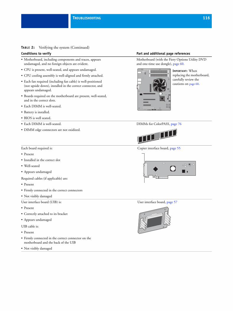
TROUBLESHOOTING 116
• Motherboard, including components and traces, appears undamaged, and no foreign objects are evident.
• CPU is present, well-seated, and appears undamaged.
• CPU cooling assembly is well-aligned and firmly attached.
• Each fan required (including fan cable) is well-positioned (not upside down), installed in the correct connector, and appears undamaged.
• Boards required on the motherboard are present, well-seated, and in the correct slots.
• Each DIMM is well-seated.
• Battery is installed.
• BIOS is well seated.
Motherboard (with the Fiery Options Utility DVD and one-time use dongle), page 60.
• Each DIMM is well-seated.
• DIMM edge connectors are not oxidized.
DIMMs for ColorPASS, page 76
Each board required is:
• Present
• Installed in the correct slot
• Well-seated
• Appears undamaged
Required cables (if applicable) are:
• Present
• Firmly connected in the correct connectors
• Not visibly damaged
Copier interface board, page 55
User interface board (UIB) is:
• Present
• Correctly attached to its bracket
• Appears undamaged
UIB cable is:
• Present
• Firmly connected in the correct connector on the motherboard and the back of the UIB
• Not visibly damaged
User interface board, page 57
TABLE 2: Verifying the system (Continued)
Conditions to verify Part and additional page references
IMPORTANT: When replacing the motherboard, carefully review the cautions on page 60.

TROUBLESHOOTING 117
CPU is:
• Present
• Well-seated
• Not visibly damaged
The CPU cooling assembly is:
• Well-aligned
• Firmly attached
CPU with cooling assembly, page 78
Fan is:
• Properly positioned (not backwards)
• Installed in the correct connector
The fan, fan cable, cable connector, and mating connectorare not visibly damaged.
Front panel fan, page 85
The power supply required is:
• Present
• Correctly installed
• Not visibly damaged
Cable connectors are:
• Firmly connected
• Not visibly damaged
• Installed in the correct devices
Power supply, page 86
The hard disk drive required is:
• Present
• Correctly installed
• Not visibly damaged
Hard disk drive data cable is:
• Present
• Firmly connected to motherboard connector SATA 1
• Not visibly damaged
Hard disk drive (HDD), page 90
TABLE 2: Verifying the system (Continued)
Conditions to verify Part and additional page references

TROUBLESHOOTING 118
The DVD drive required is:
• Present
• Correctly installed
• Not visibly damaged
• Activity LED lights on power up
DVD drive SATA cable is:
• Firmly connected to motherboard SATA 0
• Not visibly damaged
DVD drive, page 100
Each cable required is:
• Present
• The correct type
• Installed in the correct connector
• Well-seated
• Not visibly damaged (including connectors)
UIB cable, page 57
Hard disk drive data cable, page 90
Copier interface cable, page 113
DVD drive power and data combination cable, page 100
Power cable(s), page 113
TABLE 2: Verifying the system (Continued)
Conditions to verify Part and additional page references
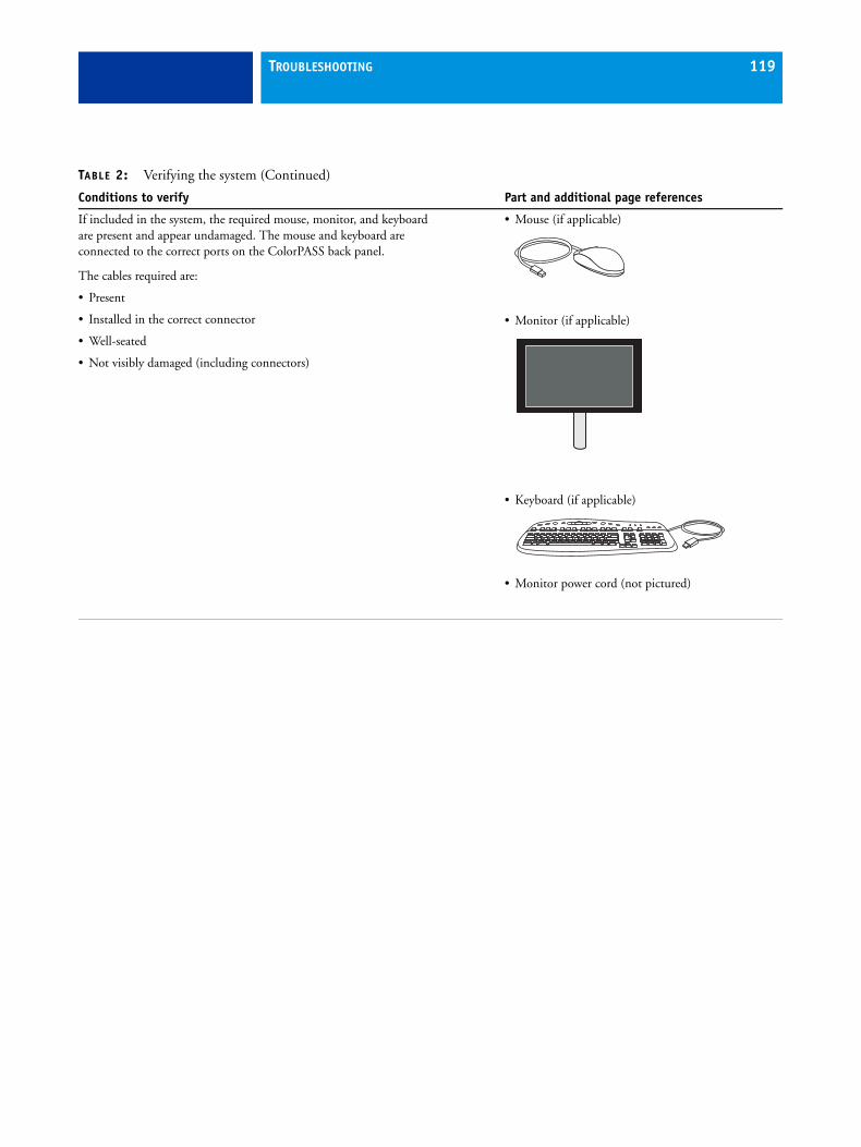
TROUBLESHOOTING 119
If included in the system, the required mouse, monitor, and keyboardare present and appear undamaged. The mouse and keyboard areconnected to the correct ports on the ColorPASS back panel.
The cables required are:
• Present
• Installed in the correct connector
• Well-seated
• Not visibly damaged (including connectors)
• Mouse (if applicable)
• Monitor (if applicable)
• Keyboard (if applicable)
• Monitor power cord (not pictured)
TABLE 2: Verifying the system (Continued)
Conditions to verify Part and additional page references
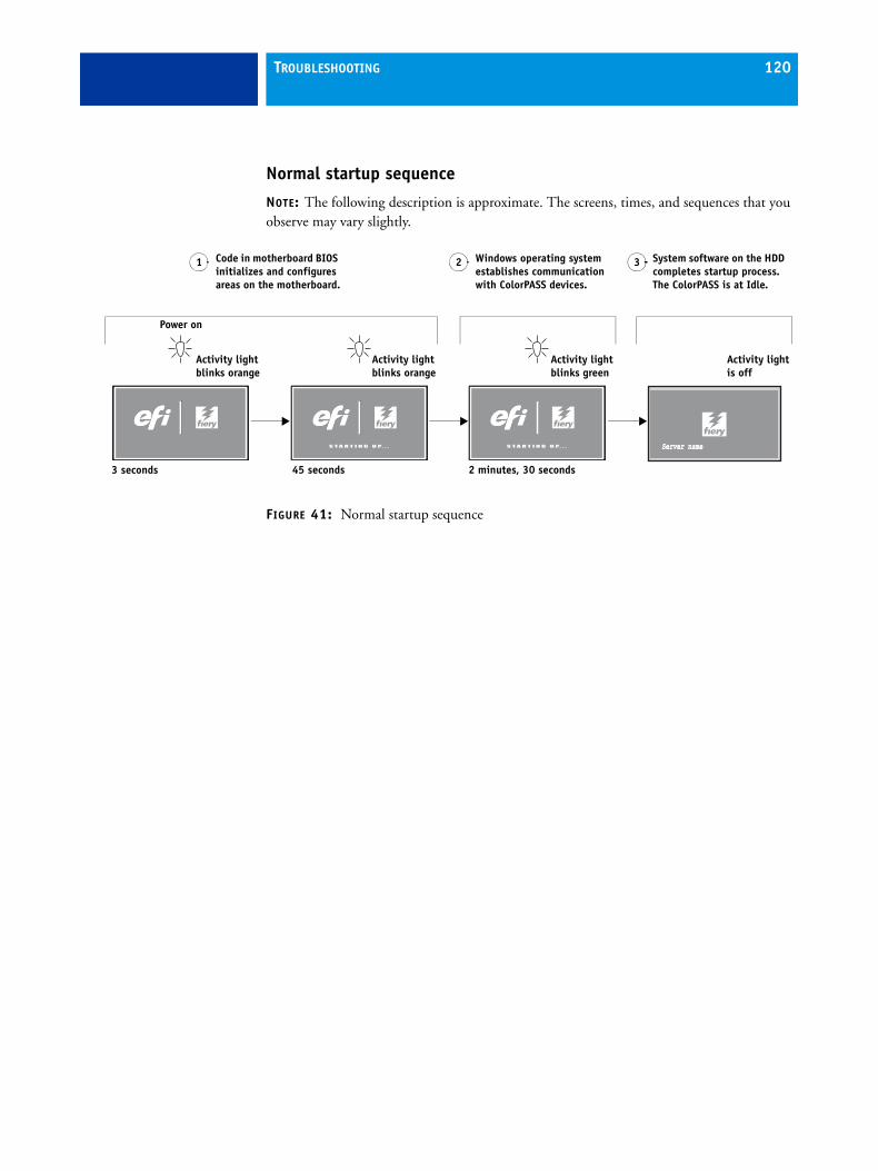
TROUBLESHOOTING 120
Normal startup sequence
NOTE: The following description is approximate. The screens, times, and sequences that you observe may vary slightly.
FIGURE 41: Normal startup sequence
Code in motherboard BIOS initializes and configures areas on the motherboard.
Windows operating system establishes communication with ColorPASS devices.
System software on the HDD completes startup process. The ColorPASS is at Idle.
Activity lightis off
3 seconds 45 seconds 2 minutes, 30 seconds
1 2 3
Power on
S T A R T I N G U P. . .
Activity light blinks orange
Server nameServer name
Activity light blinks orange
S T A R T I N G U P. . .
Activity light blinks green
TROUBLESHOOTING 121
Error messages and conditionsTo address specific error messages or conditions, see “ColorPASS error messages and condition” on page 122. Use the table to locate the problem or symptom that you want to fix, read about the possible causes, and then perform the suggested actions to solve the problem.
Do not replace the HDD and the motherboard at the same time. Doing so in the wrong order, without transferring options to the new motherboard, will cause the system to malfunction.
If troubleshooting strategies (checking cables and connections, reinstalling system software, and so forth) do not solve the problem and you suspect that the HDD or motherboard is faulty, note that it is highly unlikely that the HDD and the motherboard are both defective; therefore, avoid replacing both to solve one problem. Always troubleshoot in the following order.
• First, replace the HDD and install system software.
Always replace a faulty HDD with a new HDD. Transferring a HDD from one ColorPASS to another is incorrect and strongly discouraged.
• If the problem persists, reinstall the original HDD in the system, and then replace the motherboard.
If replacing a component does not correct the problem, make sure that you reinstall the old component back in the ColorPASS.
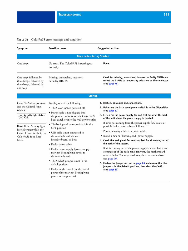
TROUBLESHOOTING 122
TABLE 3: ColorPASS error messages and condition
Symptom Possible cause Suggested action
Beep codes during Startup
One beep No error. The ColorPASS is starting up normally.
None
One beep, followed by three beeps, followed by three beeps, followed by one beep
Missing, unmatched, incorrect,or faulty DIMMs
Check for missing, unmatched, incorrect or faulty DIMMs and reseat the DIMMs to remove any oxidation on the connector (see page 76).
Startup
ColorPASS does not start and the Control Panel is black.
NOTE: If the Activity light is solid orange while the Control Panel is black, the ColorPASS is in Sleep Mode.
Possibly one of the following:
• The ColorPASS is powered off
• Power cable is not plugged into the power connector on the ColorPASS back panel, or into the wall power outlet
• The back panel power switch is in the OFF position
• UIB cable is not connected to the motherboard, the user interface board, or both
• Faulty power cable
• Faulty power supply (power supply may not be supplying power to the motherboard)
• The CMOS jumper is not in the default position
• Faulty motherboard (motherboard power plane may not be supplying power to components)
1. Recheck all cables and connections.
2. Make sure the back panel power switch is in the ON position (see page 41).
3. Listen for the power supply fan and feel for air at the back of the unit where the power supply is located.
If air is not coming from the power supply fan, isolate a possible faulty power cable as follows:
• Power on using a different power cable.
• Install a new or “known good” power supply.
4. Check the back panel fan vent and feel for air coming out of the back of the system.
If air is coming out of the power supply fan vent but is not coming out of the back panel fan vent, the motherboard may be faulty. You may need to replace the motherboard (see page 60).
5. Review the jumper section on page 83 and ensure that the jumper is in the default position, then clear the CMOS(see page 83).
Activity light status:Off.
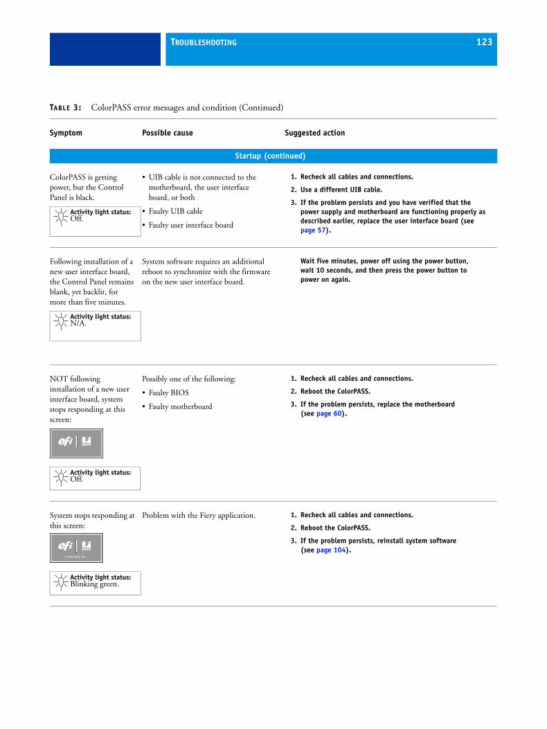
TROUBLESHOOTING 123
Startup (continued)
ColorPASS is getting power, but the Control Panel is black.
• UIB cable is not connected to the motherboard, the user interface board, or both
• Faulty UIB cable
• Faulty user interface board
1. Recheck all cables and connections.
2. Use a different UIB cable.
3. If the problem persists and you have verified that the power supply and motherboard are functioning properly as described earlier, replace the user interface board (see page 57).
Following installation of a new user interface board, the Control Panel remains blank, yet backlit, for more than five minutes.
System software requires an additional reboot to synchronize with the firmware on the new user interface board.
Wait five minutes, power off using the power button, wait 10 seconds, and then press the power button to power on again.
NOT following installation of a new user interface board, system stops responding at this screen:
Possibly one of the following:
• Faulty BIOS
• Faulty motherboard
1. Recheck all cables and connections.
2. Reboot the ColorPASS.
3. If the problem persists, replace the motherboard(see page 60).
System stops responding at this screen:
Problem with the Fiery application. 1. Recheck all cables and connections.
2. Reboot the ColorPASS.
3. If the problem persists, reinstall system software(see page 104).
TABLE 3: ColorPASS error messages and condition (Continued)
Symptom Possible cause Suggested action
Activity light status:Off.
Activity light status:N/A.
Activity light status:Off.
S T A R T I N G U P. . .
Activity light status:Blinking green.

TROUBLESHOOTING 124
Startup (continued)
Control Panel screen and Activity light appear as follows:
Possibly one of the following:
• Wrong, missing, incorrectly connected, or faulty DIMM(s)
• Faulty motherboard
1. Recheck all cables and connections.
2. Reboot the ColorPASS.
3. If the problem persists, verify that the DIMMs are installed as described in the DIMM section on page 76. DIMMs must be installed in matching pairs in alternating sockets. Check for incorrect type, wrong capacity, missing, or faulty DIMM(s). Reseat the DIMM(s) to remove any oxidation on the connector (see page 76).
4. If the problem persists, you may need to replace the motherboard (see page 60).
Control Panel screen and Activity light appear as follows:
Possibly one of the following:
• Faulty disk in the DVD drive
• Faulty motherboard
1. Reboot the ColorPASS.
2. If the problem occurs when you are installing software from bootable media (DVD or CD), the media may be damaged. Try another DVD or CD.
3. If the problem persists, replace the motherboard (see page 60).
TABLE 3: ColorPASS error messages and condition (Continued)
Symptom Possible cause Suggested action
Activity light status:Off, then solid red.
S T A R T I N G U P. . .
Activity light status:Blinking orange,then solid red.

TROUBLESHOOTING 125
Startup (continued)
Control Panel screen and Activity light appear as follows:
Problem with the Windows operating system.
1. Recheck all cables and connections.
2. Reboot the ColorPASS.
3. If the problem persists, reinstall system software(see page 104).
Activity light status progresses from solid green to solid red.
Possibly one of the following:
• Problem with system software
• Print job is corrupt or too large
• Faulty UIB cable
• CPU overheated
• Faulty motherboard
1. If you suspect that the problem may be caused by a print job, try printing a different job.
2. Recheck all cables and connections.
3. Reboot the ColorPASS and check whether the CPU cooling assembly fan is operating. If the fan is properly connected to the motherboard but does not operate, replace the cooling assembly.
4. If the problem persists, reinstall system software(see page 104).
5. If the problem persists, try connecting another UIB cable (see Figure 13 on page 48).
6. If the problem persists, replace the motherboard (see page 60).
TABLE 3: ColorPASS error messages and condition (Continued)
Symptom Possible cause Suggested action
S T A R T I N G U P. . .
Activity light status:Blinking green, then solid red.
Activity light status:Solid green, then solid red.
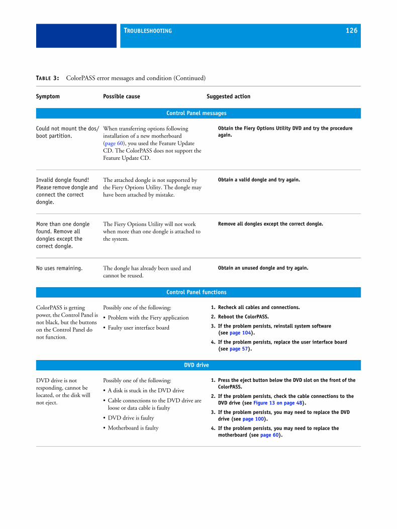
TROUBLESHOOTING 126
Control Panel messages
Could not mount the dos/boot partition.
When transferring options following installation of a new motherboard (page 60), you used the Feature Update CD. The ColorPASS does not support the Feature Update CD.
Obtain the Fiery Options Utility DVD and try the procedure again.
Invalid dongle found! Please remove dongle and connect the correct dongle.
The attached dongle is not supported by the Fiery Options Utility. The dongle may have been attached by mistake.
Obtain a valid dongle and try again.
More than one dongle found. Remove all dongles except the correct dongle.
The Fiery Options Utility will not work when more than one dongle is attached to the system.
Remove all dongles except the correct dongle.
No uses remaining. The dongle has already been used and cannot be reused.
Obtain an unused dongle and try again.
Control Panel functions
ColorPASS is getting power, the Control Panel is not black, but the buttons on the Control Panel do not function.
Possibly one of the following:
• Problem with the Fiery application
• Faulty user interface board
1. Recheck all cables and connections.
2. Reboot the ColorPASS.
3. If the problem persists, reinstall system software(see page 104).
4. If the problem persists, replace the user interface board(see page 57).
DVD drive
DVD drive is not responding, cannot be located, or the disk will not eject.
Possibly one of the following:
• A disk is stuck in the DVD drive
• Cable connections to the DVD drive are loose or data cable is faulty
• DVD drive is faulty
• Motherboard is faulty
1. Press the eject button below the DVD slot on the front of the ColorPASS.
2. If the problem persists, check the cable connections to the DVD drive (see Figure 13 on page 48).
3. If the problem persists, you may need to replace the DVD drive (see page 100).
4. If the problem persists, you may need to replace the motherboard (see page 60).
TABLE 3: ColorPASS error messages and condition (Continued)
Symptom Possible cause Suggested action

TROUBLESHOOTING 127
System performance
System performs slowly and/or hangs periodically.
Possibly one of the following:
• Board or cable connections are loose or faulty
• System software is corrupted
• Missing or faulty DIMM(s)
• CPU is overheated or faulty
• CMOS settings need to be reset or are corrupted
• Motherboard is faulty
1. Recheck all cables and connections.
2. Make sure that the CPU is firmly seated in its socket and that the fan cable is connected to the motherboard.
3. If the problem persists, reinstall the system software(see page 104).
4. Check for missing or faulty DIMM and reseat the DIMM to remove any oxidation on the connector (see page 76).
5. Clear the CMOS (see page 83).
6. If the problem persists, you may need to replace the motherboard (see page 60).
Clock is slow. • CMOS settings need to be reset or are corrupted
• Missing or dead battery on the motherboard
1. Clear the CMOS (see page 83).
2. Replace the battery on the motherboard and update the time in the Windows Control Panel (if a monitor is connected), Command WorkStation, or WebTools.
The ColorPASS hangs during the user software installation segment.
Possibly one of the following:
• The time and date need to be configured in the ColorPASS BIOS. (If the battery was removed from the ColorPASS motherboard during service and the time and date were not configured in Setup afterward, the ColorPASS will hang during the user software installation segment.)
• User Software DVD is corrupted
• The DVD drive is faulty
• The hard disk drive is faulty
1. Set the time and date in the BIOS:
• Power off the ColorPASS and remove the User Software DVD when it ejects.
• If not already connected, connect a keyboard and a monitor to the ColorPASS.
• Power on the ColorPASS and immediately press F2 repeatedly to start the BIOS setup utility.
• Configure the time and date. (To navigate, use the tab key and the -/+ keys).
• Save changes and exit (F10).
• When the ColorPASS reaches Idle, power off and then begin a full software installation again, starting with System Software DVD 1 (see page 104).
2. If the problem persists, obtain another User Software DVD and begin software installation again starting with System Software DVD 1 (see page 104).
3. If the problem persists, you may need to replace the DVD drive (see page 100).
If replacing the DVD drive does not correct the problem, reinstall the old DVD drive in the system.
4. If the problem persists, replace the hard disk drive (see page 90).
If replacing the hard disk drive does not correct the problem, reinstall the old hard disk drive in the system.
TABLE 3: ColorPASS error messages and condition (Continued)
Symptom Possible cause Suggested action
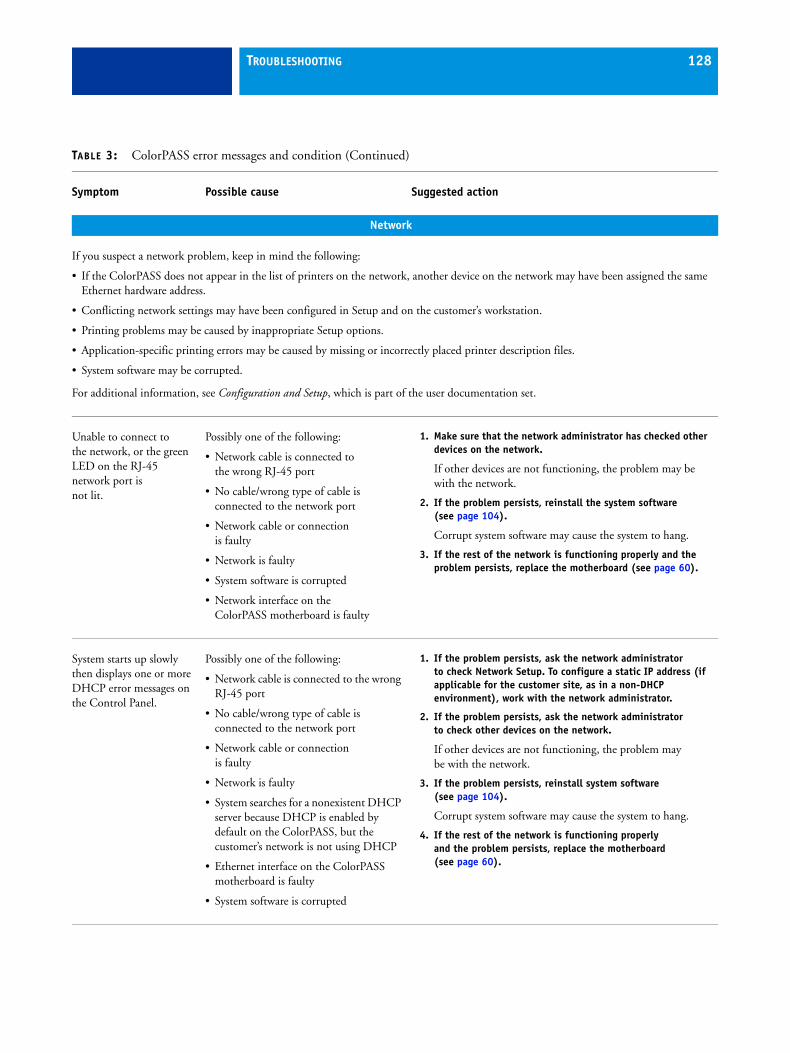
TROUBLESHOOTING 128
Network
If you suspect a network problem, keep in mind the following:
• If the ColorPASS does not appear in the list of printers on the network, another device on the network may have been assigned the same Ethernet hardware address.
• Conflicting network settings may have been configured in Setup and on the customer’s workstation.
• Printing problems may be caused by inappropriate Setup options.
• Application-specific printing errors may be caused by missing or incorrectly placed printer description files.
• System software may be corrupted.
For additional information, see Configuration and Setup, which is part of the user documentation set.
Unable to connect to the network, or the green LED on the RJ-45 network port is not lit.
Possibly one of the following:
• Network cable is connected to the wrong RJ-45 port
• No cable/wrong type of cable is connected to the network port
• Network cable or connectionis faulty
• Network is faulty
• System software is corrupted
• Network interface on the ColorPASS motherboard is faulty
1. Make sure that the network administrator has checked other devices on the network.
If other devices are not functioning, the problem may be with the network.
2. If the problem persists, reinstall the system software (see page 104).
Corrupt system software may cause the system to hang.
3. If the rest of the network is functioning properly and the problem persists, replace the motherboard (see page 60).
System starts up slowly then displays one or more DHCP error messages on the Control Panel.
Possibly one of the following:
• Network cable is connected to the wrong RJ-45 port
• No cable/wrong type of cable is connected to the network port
• Network cable or connectionis faulty
• Network is faulty
• System searches for a nonexistent DHCP server because DHCP is enabled by default on the ColorPASS, but the customer’s network is not using DHCP
• Ethernet interface on the ColorPASS motherboard is faulty
• System software is corrupted
1. If the problem persists, ask the network administrator to check Network Setup. To configure a static IP address (if applicable for the customer site, as in a non-DHCP environment), work with the network administrator.
2. If the problem persists, ask the network administrator to check other devices on the network.
If other devices are not functioning, the problem may be with the network.
3. If the problem persists, reinstall system software(see page 104).
Corrupt system software may cause the system to hang.
4. If the rest of the network is functioning properly and the problem persists, replace the motherboard (see page 60).
TABLE 3: ColorPASS error messages and condition (Continued)
Symptom Possible cause Suggested action
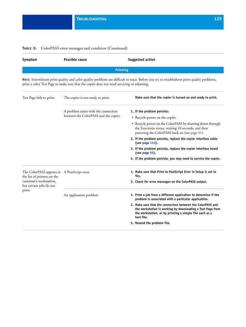
TROUBLESHOOTING 129
Printing
NOTE: Intermittent print quality and color quality problems are difficult to trace. Before you try to troubleshoot print quality problems, print a color Test Page to make sure that the copier does not need servicing or adjusting.
Test Page fails to print. The copier is not ready to print. Make sure that the copier is turned on and ready to print.
A problem exists with the connection between the ColorPASS and the copier.
1. If the problem persists:
• Recycle power on the copier.
• Recycle power on the ColorPASS by shutting down through the Functions menu, waiting 10 seconds, and then powering the ColorPASS back on (see page 41).
2. If the problem persists, replace the copier interface cable (see page 113).
3. If the problem persists, replace the copier interface board (see page 55).
4. If the problem persists, you may need to service the copier.
The ColorPASS appears in the list of printers on the customer’s workstation, but certain jobs do not print.
A PostScript error 1. Make sure that Print to PostScript Error in Setup is set to Yes.
2. Check for error messages on the ColorPASS output.
An application problem 1. Print a job from a different application to determine if the problem is associated with a particular application.
2. Make sure that the connection between the ColorPASS and the workstation is working by downloading a Test Page from the workstation, or by printing a simple file such as a text file.
3. Resend the problem file.
TABLE 3: ColorPASS error messages and condition (Continued)
Symptom Possible cause Suggested action

TROUBLESHOOTING 130
Printing (continued)
A print job stalls or stops after one or a few pages.
Possibly one of the following:
• A PostScript or application error
• System software is corrupted
1. Cancel the ColorPASS print job.
2. If this fails to clear the problem, reboot the ColorPASS (see page 41).
3. If the problem persists, choose the Clear Server command from Command WorkStation.
4. Set Print Cover Page to Yes and resend the problem job. The Cover Page will indicate “PS Error.”
For more information about the PostScript error, double-click the problem job in the Command WorkStation window.
5. If the problem persists, reinstall system software (see page 104).
Corrupt system software may cause the system to hang.
Incorrect or faulty DIMMor faulty DIMM connection
1. Reseat the DIMMs to remove any oxidation on the connectors (see page 76).
2. Verify memory amount on the Configuration page.
3. If the problem persists after replacing the DIMM, replace the motherboard (see page 60).
Color quality isinconsistent.
A copier problem Test the copier and perform service, if necessary. See the service documentation that accompanies the copier.
TABLE 3: ColorPASS error messages and condition (Continued)
Symptom Possible cause Suggested action
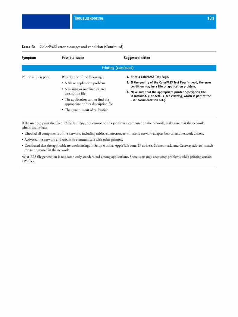
TROUBLESHOOTING 131
Printing (continued)
Print quality is poor. Possibly one of the following:
• A file or application problem
• A missing or outdated printerdescription file
• The application cannot find the appropriate printer description file
• The system is out of calibration
1. Print a ColorPASS Test Page.
2. If the quality of the ColorPASS Test Page is good, the error condition may be a file or application problem.
3. Make sure that the appropriate printer description file is installed. (For details, see Printing, which is part of the user documentation set.)
If the user can print the ColorPASS Test Page, but cannot print a job from a computer on the network, make sure that the network administrator has:
• Checked all components of the network, including cables, connectors, terminators, network adapter boards, and network drivers.
• Activated the network and used it to communicate with other printers.
• Confirmed that the applicable network settings in Setup (such as AppleTalk zone, IP address, Subnet mask, and Gateway address) match the settings used in the network.
NOTE: EPS file generation is not completely standardized among applications. Some users may encounter problems while printing certain EPS files.
TABLE 3: ColorPASS error messages and condition (Continued)
Symptom Possible cause Suggested action
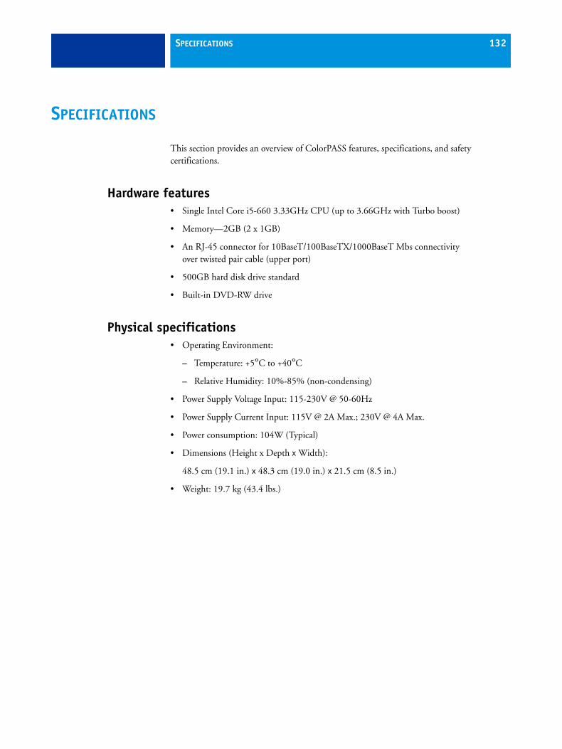
SPECIFICATIONS 132
SPECIFICATIONS
This section provides an overview of ColorPASS features, specifications, and safety certifications.
Hardware features• Single Intel Core i5-660 3.33GHz CPU (up to 3.66GHz with Turbo boost)
• Memory—2GB (2 x 1GB)
• An RJ-45 connector for 10BaseT/100BaseTX/1000BaseT Mbs connectivity over twisted pair cable (upper port)
• 500GB hard disk drive standard
• Built-in DVD-RW drive
Physical specifications• Operating Environment:
– Temperature: +5°C to +40°C
– Relative Humidity: 10%-85% (non-condensing)
• Power Supply Voltage Input: 115-230V @ 50-60Hz
• Power Supply Current Input: 115V @ 2A Max.; 230V @ 4A Max.
• Power consumption: 104W (Typical)
• Dimensions (Height x Depth x Width):
48.5 cm (19.1 in.) x 48.3 cm (19.0 in.) x 21.5 cm (8.5 in.)
• Weight: 19.7 kg (43.4 lbs.)

SPECIFICATIONS 133
Networking and connectivity• Supports AppleTalk and TCP/IP protocols simultaneously.
• Supports EtherTalk Phase 2 (allows users to print from a Mac OS computer to the ColorPASS using the AppleTalk network protocol over an Ethernet network).
• RJ-45 connector (upper port) that supports 10BaseT/100BaseTX/1000BaseT twisted pair network connectivity.
• RJ-45 connector (lower port) that provides the Command/Status interface between the ColorPASS and the copier.
NOTE: The network cable at the customer site and the Command/Status Ethernet Crossover cable included with the ColorPASS are not interchangeable. Make sure to attach the correct cable to the appropriate RJ-45 port on the ColorPASS back panel (see page 28).
User softwareA complete description of user software is provided in Welcome from the user documentation set. For optimal performance, maintain current versions of the user software on every network computer used to print to the ColorPASS. User software may be installed directly on client computers equipped with a DVD drive, or over a network via the Fiery User Software Installer that resides on the ColorPASS.
Safety and emissions complianceThe ColorPASS has been certified to meet or surpass the following government standards:
Safety approvals EMI/EMC approvals
• UL 60950-1 (TUV/CU mark) • FCC Class B
• CSA 22.2 #60950-1 • VCCI Class B
• EN 60950-1 (TUV/GS mark) • EN55022 Class B
• CB scheme IEC 60950-1 • EN55024
• AS/NZS CISPR22: 2004 Class B

SERVICING THE COLORPASS WITH FURNITURE 134
SERVICING THE COLORPASS WITH FURNITURE
This chapter describes how to remove the ColorPASS from the furniture in order to access internal components for service.
ProceduresIf the ColorPASS is installed in the optional furniture, you must remove it from the furniture before performing most service procedures.
FIGURE 42: ColorPASS installed on the furniture
Drawer
ColorPASS
Table top
Monitor
Monitor pole
Stand

SERVICING THE COLORPASS WITH FURNITURE 135
REMOVING THE COLORPASS FROM THE FURNITURE
Never lift the ColorPASS by grasping the top panel. The top panel does not support the weight of the system.
1 Make sure that the ColorPASS is shut down and that all the cables are removed from the back of the ColorPASS.
2 Remove the cable cover and disconnect the two monitor cables (power and video):
• Power from the back of the monitor and from the wall outlet
• Video from the back of the monitor and from the back of the ColorPASS
Video cable
Cable cover
Power cable
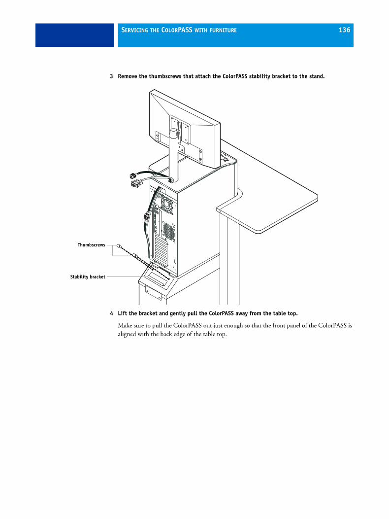
SERVICING THE COLORPASS WITH FURNITURE 136
3 Remove the thumbscrews that attach the ColorPASS stability bracket to the stand.
4 Lift the bracket and gently pull the ColorPASS away from the table top.
Make sure to pull the ColorPASS out just enough so that the front panel of the ColorPASS is aligned with the back edge of the table top.
Stability bracket
Thumbscrews

SERVICING THE COLORPASS WITH FURNITURE 137
5 Remove the ColorPASS left side panel (two screws) so that you can access the monitor pole tightening mechanism.
Monitor poletightening mechanism
Left side panel

SERVICING THE COLORPASS WITH FURNITURE 138
6 Use the allen key to loosen the screw that secures the monitor pole to the ColorPASS.
The allen key should be stored in the side drawer of the furniture.
7 Holding the monitor pole, gently lift the monitor pole assembly up and out of the ColorPASS monitor mount.
8 Continue with the procedure “To open the ColorPASS” on page 51.
Allen key
Monitor pole
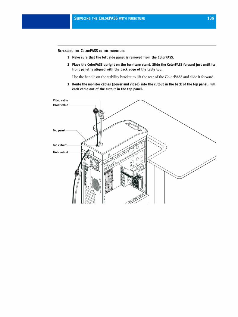
SERVICING THE COLORPASS WITH FURNITURE 139
REPLACING THE COLORPASS IN THE FURNITURE
1 Make sure that the left side panel is removed from the ColorPASS.
2 Place the ColorPASS upright on the furniture stand. Slide the ColorPASS forward just until its front panel is aligned with the back edge of the table top.
Use the handle on the stability bracket to lift the rear of the ColorPASS and slide it forward.
3 Route the monitor cables (power and video) into the cutout in the back of the top panel. Pull each cable out of the cutout in the top panel.
Video cable
Power cable
Top cutout
Back cutout
Top panel

SERVICING THE COLORPASS WITH FURNITURE 140
4 Lift up the pole assembly and insert the pole into the top of the ColorPASS so that it is inside the monitor mount. Tighten the assembly into place using the allen key.
Tighten the monitor assembly

SERVICING THE COLORPASS WITH FURNITURE 141
5 Replace the left side panel on the ColorPASS with the screws that you removed earlier.

SERVICING THE COLORPASS WITH FURNITURE 142
6 Use the handle on the stability bracket to lift the rear of the ColorPASS. Slide the ColorPASS all the way forward into the stand. Lock the ColorPASS into place with the two thumbscrews that you removed earlier.
7 Connect the two monitor cables (power and video):
• Power to the back of the monitor and to the wall outlet
• Video to the back of the monitor and to the back of the ColorPASS
Stability bracket (lock into place with two thumbscrews)
Video cable
Power cable

SERVICING THE COLORPASS WITH FURNITURE 143
8 Replace the cable cover over the cables and monitor pole.
9 Replace the allen key in the furniture drawer and continue with the procedure “To reassemble the ColorPASS and verify functionality” on page 103.
Cable cover

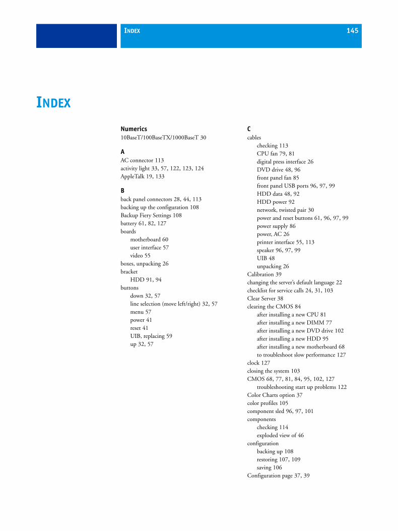
INDEX 145
Numerics10BaseT/100BaseTX/1000BaseT 30
AAC connector 113activity light 33, 57, 122, 123, 124AppleTalk 19, 133
Bback panel connectors 28, 44, 113backing up the configuration 108Backup Fiery Settings 108battery 61, 82, 127boards
motherboard 60user interface 57video 55
boxes, unpacking 26bracket
HDD 91, 94buttons
down 32, 57line selection (move left/right) 32, 57menu 57power 41reset 41UIB, replacing 59up 32, 57
Ccables
checking 113CPU fan 79, 81digital press interface 26DVD drive 48, 96front panel fan 85front panel USB ports 96, 97, 99HDD data 48, 92HDD power 92network, twisted pair 30power and reset buttons 61, 96, 97, 99power supply 86power, AC 26printer interface 55, 113speaker 96, 97, 99UIB 48unpacking 26
Calibration 39changing the server’s default language 22checklist for service calls 24, 31, 103Clear Server 38clearing the CMOS 84
after installing a new CPU 81after installing a new DIMM 77after installing a new DVD drive 102after installing a new HDD 95after installing a new motherboard 68to troubleshoot slow performance 127
clock 127closing the system 103CMOS 68, 77, 81, 84, 95, 102, 127
troubleshooting start up problems 122Color Charts option 37color profiles 105component sled 96, 97, 101components
checking 114exploded view of 46
configurationbacking up 108restoring 107, 109saving 106
Configuration page 37, 39
INDEX
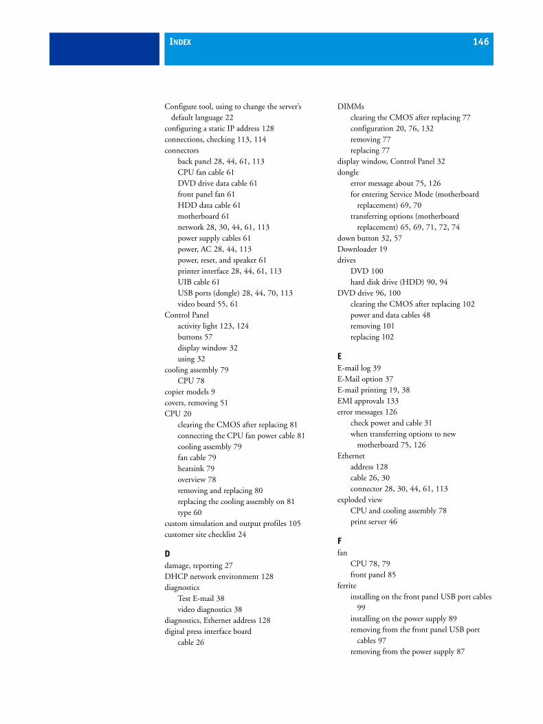
INDEX 146
Configure tool, using to change the server’s default language 22
configuring a static IP address 128connections, checking 113, 114connectors
back panel 28, 44, 61, 113CPU fan cable 61DVD drive data cable 61front panel fan 61HDD data cable 61motherboard 61network 28, 30, 44, 61, 113power supply cables 61power, AC 28, 44, 113power, reset, and speaker 61printer interface 28, 44, 61, 113UIB cable 61USB ports (dongle) 28, 44, 70, 113video board 55, 61
Control Panelactivity light 123, 124buttons 57display window 32using 32
cooling assembly 79CPU 78
copier models 9covers, removing 51CPU 20
clearing the CMOS after replacing 81connecting the CPU fan power cable 81cooling assembly 79fan cable 79heatsink 79overview 78removing and replacing 80replacing the cooling assembly on 81type 60
custom simulation and output profiles 105customer site checklist 24
Ddamage, reporting 27DHCP network environment 128diagnostics
Test E-mail 38video diagnostics 38
diagnostics, Ethernet address 128digital press interface board
cable 26
DIMMsclearing the CMOS after replacing 77configuration 20, 76, 132removing 77replacing 77
display window, Control Panel 32dongle
error message about 75, 126for entering Service Mode (motherboard
replacement) 69, 70transferring options (motherboard
replacement) 65, 69, 71, 72, 74down button 32, 57Downloader 19drives
DVD 100hard disk drive (HDD) 90, 94
DVD drive 96, 100clearing the CMOS after replacing 102power and data cables 48removing 101replacing 102
EE-mail log 39E-Mail option 37E-mail printing 19, 38EMI approvals 133error messages 126
check power and cable 31when transferring options to new
motherboard 75, 126Ethernet
address 128cable 26, 30connector 28, 30, 44, 61, 113
exploded viewCPU and cooling assembly 78print server 46
Ffan
CPU 78, 79front panel 85
ferriteinstalling on the front panel USB port cables
99installing on the power supply 89removing from the front panel USB port
cables 97removing from the power supply 87
INDEX 147
Fiery Options Utility 72Fiery pages 39Fiery Scan 19Fiery.1 password 71, 75Font list
definition 104printing prior to HDD replacement 92printing prior to system software installation
104fonts 19front panel 28, 44, 113
buttons 41fan 85layout 32removing 53
front panel USB ports 96FTP Log 37functional diagram 21Functions menu 34, 36
Calibration 39Color Charts 37Configuration page 37e-mail Log 37Job Log 37Run Diagnostics 38Scan job 38Shut Down 34, 38, 41, 48System Updates 39Tray Alignment 38
Hhard disk drive (HDD) 90, 94
bracket 91, 92, 94capacity 132caution about replacing 94, 121clearing the CMOS after replacing 95data cable 92description 90mounting screws 93, 94proper handling 90removing 92replacing 94
heatsink, CPU 78, 79
Iinstallation sequence 22, 23installing user software on client systems 25, 133IP address, static 128IPP 19
JJob Log 104
option in Functions menu 37printing 37
jobs 104jumpers 84
Llanguage, changing the default 22LCD 32, 33, 57line selection buttons 32, 57Logon Information password 71, 75
Mmaster installer 25, 133media package 26memory
configuration 20, 76, 132removing 77replacing 77
menu button 57menu, Functions 36monitor profiles 105motherboard
battery 61, 82cautions about replacing 64clearing the CMOS after replacing 68connectors 61description 60DIMMs 76, 77errors when transferring options to 75, 126illustration 61mounting holes 61removing 60, 63replacing 64transferring options to 65, 69, 71, 72, 74verifying in Service Mode 64, 69–71
move left/right buttons 57
Nnetwork
cable, twisted pair 30connector 28, 30, 44, 61, 113supported types 133
network administrator 22, 25networks
availability during installation 25checklist 25supported 19, 20
normal startup sequence 120

INDEX 148
Oopening the system 51
Ppanels, removing 51, 53password 71, 75Portable Document Format (PDF) 19PostScript 19power
AC cable 26, 113AC connector 113CPU fan 81DVD drive 102front panel fan 85HDD 94power and reset cables 47, 48precautions 24
power and reset buttons 41, 96power supply
cables 86removing 87replacing 89voltages 31, 41, 86, 132
power, ACconnector 28, 44, 113
Print E-mail Log option 37printing
Color Charts 37Configuration page 37e-mail Log 37Job Log 37
profiles 105
Rreassembling the system 103reset and power buttons 34, 41, 48reset button 41, 49
motherboard connector for 61Restore Fiery Settings 107, 109restoring the configuration 107, 109reusable tie-wrap 87, 89Run Diagnostics 38
Ssafety approvals 133saving the configuration 108scanning 19, 38screens
Functions 36service calls
checklist 24, 31, 103
service dongle 72Service Mode 64, 69–71service procedures, overview 43shutting down 34, 38, 41, 42, 48, 49, 50side panels
removing 52replacing 52
slot assignments, motherboard 60, 61, 113software
media package 26system 65, 104user 25, 65, 104, 133
speakermotherboard connection 47, 48removing 97, 99
specifications 132startup 41
normal sequence 120static IP address, configuring 128supported copier series 9switch bank assembly 96, 101
removing 97replacing 99
system performance 127system software 104
do not install after installing a new motherboard 65
installing or upgrading 108–109system updates 39, 110system upgrade 108–109
Tterminology 43Test E-mail 38Test Page 39thermal compound 66, 81tie-wrap, reusable 87, 89transferring options (motherboard replacement)
65, 69, 71, 72, 74Tray Alignment 38

INDEX 149
troubleshootingbeep codes during startup 122checking external connections 113checking internal connections 114control panel functions 126control panel messages 126DVD drive 126error messages and conditions 121network 128normal startup sequence 120preliminary on-site checkout 112printing 129startup problems 122system performance 127
twisted pair network cable 30
UUIB cable
routing diagram 48unpacking 26up button 32, 57updating software 39, 110updating the system 69upgrading software 108–109USB ports 61, 96, 113user documentation 26user interface board (UIB)
activity light 57buttons on 59description 57display window 57line selection buttons (move left/right
buttons) 57menu button 57removing 58replacing 59up/down buttons 57
user software 104, 133do not install after installing a new
motherboard 65installing 108installing on client systems 25troubleshooting problems during installation
127User Software DVD 108
Vverifying functionality 103verifying new motherboard installation 69
video boardconnector 55, 61description 55removing 56replacing 56
video diagnostics 38voltages
checking 31, 41, 86
WWindows XPe
password 71, 75