service manual - canon globaldownloads.canon.com/isg_manuals/imageprograf_ipf8400s_sm_rev… ·...
TRANSCRIPT

Canon September 4, 2013 Rev. 0
SERVICE MANUAL
imagePROGRAF iPF8000 Series iPF8400S
COPYRIGHT © 2013 CANON INC. CANON imagePROGRAF iPF8400S Rev.0 PRINTED IN U.S.A


ApplicationThis manual has been issued by Canon Inc. for qualified persons to learn technical theory, installation, maintenance, and repair
of products. This manual covers all localities where the products are sold. For this reason, there may be information in this
manual that does not apply to your locality.
CorrectionsThis manual may contain technical inaccuracies or typographical errors due to improvements or changes in products. When
changes occur in applicable products or in the contents of this manual, Canon will release technical information as the need
arises. In the event of major changes in the contents of this manual over a long or short period, Canon will issue a new edition
of this manual.
The following paragraph does not apply to any countries where such provisions are inconsistent with local law.
TrademarksThe product names and company names used in this manual are the registered trademarks of the individual companies.
CopyrightThis manual is copyrighted with all rights reserved. Under the copyright laws, this manual may not be copied, reproduced or
translated into another language, in whole or in part, without the written consent of Canon Inc.
COPYRIGHT © 2001 CANON INC.Printed in Japan
CautionUse of this manual should be strictly supervised to avoid disclosure of confidential information.

Introduction
Symbols UsedThis documentation uses the following symbols to indicate special information:
Symbol Description
Indicates an item of a non-specific nature, possibly classified as Note, Caution, or Warning.
Indicates an item requiring care to avoid electric shocks.
Indicates an item requiring care to avoid combustion (fire).
Indicates an item prohibiting disassembly to avoid electric shocks or problems.
Indicates an item requiring disconnection of the power plug from the electric outlet.
Indicates an item intended to provide notes assisting the understanding of the topic in question.
Indicates an item of reference assisting the understanding of the topic in question.
Provides a description of a service mode.
Provides a description of the nature of an error indication.
Memo
REF.

Introduction
The following rules apply throughout this Service Manual:1. Each chapter contains sections explaining the purpose of specific functions and the relationship between electrical and mechanical systems with refer-
ence to the timing of operation.In the diagrams, represents the path of mechanical drive; where a signal name accompanies the symbol , the arrow indicates thedirection of the electric signal.The expression "turn on the power" means flipping on the power switch, closing the front door, and closing the delivery unit door, which results insupplying the machine with power.
2. In the digital circuits, '1'is used to indicate that the voltage level of a given signal is "High", while '0' is used to indicate "Low".(The voltage value, how-ever, differs from circuit to circuit.) In addition, the asterisk (*) as in "DRMD*" indicates that the DRMD signal goes on when '0'.In practically all cases, the internal mechanisms of a microprocessor cannot be checked in the field. Therefore, the operations of the microprocessorsused in the machines are not discussed: they are explained in terms of from sensors to the input of the DC controller PCB and from the output of theDC controller PCB to the loads.
The descriptions in this Service Manual are subject to change without notice for product improvement or other purposes, and major changes will be com-municated in the form of Service Information bulletins.All service persons are expected to have a good understanding of the contents of this Service Manual and all relevant Service Information bulletins and beable to identify and isolate faults in the machine."


Contents
Contents
Chapter 1 PRODUCT DESCRIPTION
1.1 Product Overview .......................................................................................................................................1- 11.1.1 Product Overview ....................................................................................................................................................1- 1
1.2 Features .....................................................................................................................................................1- 31.2.1 Features ..................................................................................................................................................................1- 31.2.2 Printhead ................................................................................................................................................................. 1- 31.2.3 Ink Tank...................................................................................................................................................................1- 31.2.4 Cutter Unit ...............................................................................................................................................................1- 41.2.5 Roll Holder...............................................................................................................................................................1- 41.2.6 Stand .......................................................................................................................................................................1- 51.2.7 Media Take-up Unit .................................................................................................................................................1- 61.2.8 Hard Disk Drive .......................................................................................................................................................1- 71.2.9 Consumables...........................................................................................................................................................1- 7
1.3 Product Specifications ................................................................................................................................1- 81.3.1 Product Specifications .............................................................................................................................................1- 8
1.4 Detailed Specifications ...............................................................................................................................1- 91.4.1 Interface Specifications ...........................................................................................................................................1- 9
1.5 Names and Functions of Components .....................................................................................................1- 101.5.1 Front ......................................................................................................................................................................1- 101.5.2 Rear.......................................................................................................................................................................1- 111.5.3 Top Cover (Inside)................................................................................................................................................. 1- 121.5.4 Carriage.................................................................................................................................................................1- 131.5.5 Ink Tank Cover (Inside) .........................................................................................................................................1- 14
1.6 Basic Operation ........................................................................................................................................1- 151.6.1 Operation Panel.....................................................................................................................................................1- 151.6.2 Display...................................................................................................................................................................1- 161.6.3 Main Menu.............................................................................................................................................................1- 171.6.4 Basket Unit ............................................................................................................................................................1- 33
1.7 Safety and Precautions ............................................................................................................................1- 391.7.1 Safety Precautions ................................................................................................................................................1- 39
1.7.1.1 Moving Parts .......................................................................................................................................................................... 1- 391.7.1.2 Adhesion of Ink ...................................................................................................................................................................... 1- 401.7.1.3 Electric Parts.......................................................................................................................................................................... 1- 42
1.7.2 Other Precautions..................................................................................................................................................1- 431.7.2.1 Printhead................................................................................................................................................................................ 1- 431.7.2.2 Ink Tank ................................................................................................................................................................................. 1- 441.7.2.3 Handling the Printer ............................................................................................................................................................... 1- 45
1.7.3 Precautions When Servicing Printer......................................................................................................................1- 471.7.3.1 Notes on the Data Stored in the Printer ................................................................................................................................. 1- 471.7.3.2 Confirming the Firmware Version .......................................................................................................................................... 1- 471.7.3.3 Precautions against Static Electricity ..................................................................................................................................... 1- 471.7.3.4 Precautions for Disassembly/Reassembly............................................................................................................................. 1- 471.7.3.5 Self-diagnostic Feature .......................................................................................................................................................... 1- 471.7.3.6 Disposing of the Lithium Battery ............................................................................................................................................ 1- 48
Chapter 2 TECHNICAL REFERENCE
2.1 Basic Operation Outline..............................................................................................................................2- 12.1.1 Printer Diagram .......................................................................................................................................................2- 12.1.2 Print Signal Sequence .............................................................................................................................................2- 22.1.3 Print Driving .............................................................................................................................................................2- 3

Contents
2.2 Firmware .................................................................................................................................................... 2- 52.2.1 Operation Sequence at Power-on............................................................................................................................2- 52.2.2 Operation Sequence at Power-off............................................................................................................................2- 62.2.3 Print Position Adjustment Function ..........................................................................................................................2- 72.2.4 Head Management ..................................................................................................................................................2- 72.2.5 Printhead Overheating Protection Control ...............................................................................................................2- 72.2.6 Pause between Pages .............................................................................................................................................2- 72.2.7 White Raster Skip ....................................................................................................................................................2- 72.2.8 Sleep Mode..............................................................................................................................................................2- 72.2.9 Hard Disk Drive........................................................................................................................................................2- 8
2.3 Printer Mechanical System......................................................................................................................... 2- 92.3.1 Outline......................................................................................................................................................................2- 9
2.3.1.1 Outline...................................................................................................................................................................................... 2- 92.3.2 Ink Passage ...........................................................................................................................................................2- 10
2.3.2.1 Ink Passage ........................................................................................................................................................................... 2- 102.3.2.2 Ink Tank Unit.......................................................................................................................................................................... 2- 112.3.2.3 Carriage Unit.......................................................................................................................................................................... 2- 132.3.2.4 Printhead................................................................................................................................................................................ 2- 162.3.2.5 Purge Unit .............................................................................................................................................................................. 2- 172.3.2.6 Maintenance Cartridge........................................................................................................................................................... 2- 212.3.2.7 Air Flow .................................................................................................................................................................................. 2- 22
2.3.3 Paper Path .............................................................................................................................................................2- 232.3.3.1 Outline.................................................................................................................................................................................... 2- 232.3.3.2 Paper Path ............................................................................................................................................................................. 2- 242.3.3.3 Cutter Unit.............................................................................................................................................................................. 2- 25
2.4 Printer Electrical System .......................................................................................................................... 2- 262.4.1 Outline....................................................................................................................................................................2- 26
2.4.1.1 Overview ................................................................................................................................................................................ 2- 262.4.2 Main Controller.......................................................................................................................................................2- 28
2.4.2.1 Main controller PCB components .......................................................................................................................................... 2- 282.4.3 Carriage Relay PCB...............................................................................................................................................2- 30
2.4.3.1 Carriage relay PCB components ........................................................................................................................................... 2- 302.4.4 Head Relay PCB....................................................................................................................................................2- 30
2.4.4.1 Head relay PCB components................................................................................................................................................. 2- 302.4.5 Motor Driver ...........................................................................................................................................................2- 31
2.4.5.1 Media take-up PCB components ........................................................................................................................................... 2- 312.4.6 Maintenance Cartridge Relay PCB........................................................................................................................2- 31
2.4.6.1 Maintenance cartridge relay PCB components...................................................................................................................... 2- 312.4.7 Power Supply.........................................................................................................................................................2- 31
2.4.7.1 Power supply block diagram .................................................................................................................................................. 2- 312.5 Detection Functions with Sensors ............................................................................................................ 2- 32
2.5.1 Covers....................................................................................................................................................................2- 322.5.2 Ink passage system ...............................................................................................................................................2- 332.5.3 Carriage system.....................................................................................................................................................2- 352.5.4 Paper path system.................................................................................................................................................2- 372.5.5 Media take-up Unit.................................................................................................................................................2- 382.5.6 Others ....................................................................................................................................................................2- 38
Chapter 3 INSTALLATION
3.1 Transporting the Printer.............................................................................................................................. 3- 13.1.1 Transporting the Printer ...........................................................................................................................................3- 1
3.1.1.1 Transporting the Printer ........................................................................................................................................................... 3- 13.1.2 Reinstalling the Printer...........................................................................................................................................3- 14
3.1.2.1 Reinstalling the Printer........................................................................................................................................................... 3- 14
Chapter 4 DISASSEMBLY/REASSEMBLY

Contents
4.1 Service Parts ..............................................................................................................................................4- 14.1.1 Service Parts ...........................................................................................................................................................4- 1
4.2 Disassembly/Reassembly...........................................................................................................................4- 24.2.1 Disassembly/Reassembly .......................................................................................................................................4- 2
4.3 Points to Note on Disassembly and Reassembly .......................................................................................4- 54.3.1 Note: Items that should never be disassembled......................................................................................................4- 54.3.2 Moving the carriage manually.................................................................................................................................. 4- 54.3.3 Units requiring draining of ink .................................................................................................................................. 4- 54.3.4 External Covers .......................................................................................................................................................4- 64.3.5 Drive Unit............................................................................................................................................................... 4- 144.3.6 Carriage Unit .........................................................................................................................................................4- 154.3.7 Ink Tube Unit .........................................................................................................................................................4- 204.3.8 Feeder Unit............................................................................................................................................................4- 224.3.9 Purge Unit..............................................................................................................................................................4- 234.3.10 Ink Tank Unit........................................................................................................................................................4- 244.3.11 Linear Encoder ....................................................................................................................................................4- 274.3.12 Head Management Sensor..................................................................................................................................4- 284.3.13 PCBs....................................................................................................................................................................4- 294.3.14 Opening the Cap/Moving the Wiper Unit .............................................................................................................4- 304.3.15 Opening and closing ink supply valves................................................................................................................4- 314.3.16 Draining the ink....................................................................................................................................................4- 32
4.4 Applying the Grease .................................................................................................................................4- 334.4.1 Applying the Grease .............................................................................................................................................. 4- 33
4.5 Adjustment and Setup Items ....................................................................................................................4- 364.5.1 Adjustment Item List .............................................................................................................................................. 4- 364.5.2 Procedure after Replacing the Carriage Unit or Multi Sensor ...............................................................................4- 364.5.3 Procedure after Replacing the Feed Roller or Feed Roller Encoder .....................................................................4- 364.5.4 Procedure after Replacing the Head Management Sensor...................................................................................4- 36
Chapter 5 MAINTENANCE
5.1 Periodic Replacement Parts .......................................................................................................................5- 15.1.1 Periodic Replacement Parts ....................................................................................................................................5- 1
5.2 Consumable Parts ......................................................................................................................................5- 15.2.1 Consumable Parts ................................................................................................................................................... 5- 1
5.3 Periodic Maintenance .................................................................................................................................5- 25.3.1 Periodic Maintenance ..............................................................................................................................................5- 2
Chapter 6 TROUBLESHOOTING
6.1 Troubleshooting..........................................................................................................................................6- 16.1.1 Outline .....................................................................................................................................................................6- 1
6.1.1.1 Outline of Troubleshooting....................................................................................................................................................... 6- 16.2 Location of Connectors and Pin Arrangement............................................................................................6- 1
6.2.1 Main controller PCB.................................................................................................................................................6- 16.2.2 Carriage relay PCB................................................................................................................................................6- 126.2.3 Head relay PCB.....................................................................................................................................................6- 21
6.3 Version Up................................................................................................................................................6- 296.3.1 Firmware Update Tool ...........................................................................................................................................6- 29
6.4 Service Tools ............................................................................................................................................6- 336.4.1 Tool List .................................................................................................................................................................6- 33
Chapter 7 SERVICE MODE
7.1 Service Mode..............................................................................................................................................7- 17.1.1 Service Mode Operation..........................................................................................................................................7- 1

Contents
7.1.2 Map of the Service Mode.........................................................................................................................................7- 27.1.3 Details of Service Mode.........................................................................................................................................7- 117.1.4 e-Maintenance/imageWARE Remote ....................................................................................................................7- 287.1.5 Viewing PRINT INF................................................................................................................................................7- 38
7.2 Special Mode............................................................................................................................................ 7- 537.2.1 Special Modes for Servicing ..................................................................................................................................7- 53
Chapter 8 ERROR CODE
8.1 Outline ........................................................................................................................................................ 8- 18.1.1 Outline......................................................................................................................................................................8- 1
8.2 Warning Table ............................................................................................................................................ 8- 28.2.1 Warnings..................................................................................................................................................................8- 2
8.3 Error Table ................................................................................................................................................. 8- 58.3.1 Errors .......................................................................................................................................................................8- 5
8.4 Sevice Call Table ..................................................................................................................................... 8- 168.4.1 Service Call Errors .................................................................................................................................................8- 16

Chapter 1 PRODUCT DESCRIPTION


Contents
Contents
1.1 Product Overview ..........................................................................................................................................................1-11.1.1 Product Overview ........................................................................................................................................................................ 1-1
1.2 Features ..........................................................................................................................................................................1-31.2.1 Features ........................................................................................................................................................................................ 1-31.2.2 Printhead ...................................................................................................................................................................................... 1-31.2.3 Ink Tank ....................................................................................................................................................................................... 1-31.2.4 Cutter Unit ................................................................................................................................................................................... 1-41.2.5 Roll Holder................................................................................................................................................................................... 1-41.2.6 Stand ............................................................................................................................................................................................ 1-51.2.7 Media Take-up Unit ..................................................................................................................................................................... 1-61.2.8 Hard Disk Drive ........................................................................................................................................................................... 1-71.2.9 Consumables ................................................................................................................................................................................ 1-7
1.3 Product Specifications....................................................................................................................................................1-81.3.1 Product Specifications ................................................................................................................................................................. 1-8
1.4 Detailed Specifications ..................................................................................................................................................1-91.4.1 Interface Specifications................................................................................................................................................................ 1-9
1.5 Names and Functions of Components .........................................................................................................................1-101.5.1 Front ........................................................................................................................................................................................... 1-101.5.2 Rear ............................................................................................................................................................................................ 1-111.5.3 Top Cover (Inside) ..................................................................................................................................................................... 1-121.5.4 Carriage...................................................................................................................................................................................... 1-131.5.5 Ink Tank Cover (Inside)............................................................................................................................................................. 1-14
1.6 Basic Operation............................................................................................................................................................1-151.6.1 Operation Panel.......................................................................................................................................................................... 1-151.6.2 Display ....................................................................................................................................................................................... 1-161.6.3 Main Menu................................................................................................................................................................................. 1-171.6.4 Basket Unit................................................................................................................................................................................. 1-33
1.7 Safety and Precautions .................................................................................................................................................1-391.7.1 Safety Precautions...................................................................................................................................................................... 1-39
1.7.1.1 Moving Parts .................................................................................................................................................................................................1-391.7.1.2 Adhesion of Ink.............................................................................................................................................................................................1-401.7.1.3 Electric Parts .................................................................................................................................................................................................1-42
1.7.2 Other Precautions....................................................................................................................................................................... 1-431.7.2.1 Printhead .......................................................................................................................................................................................................1-431.7.2.2 Ink Tank ........................................................................................................................................................................................................1-441.7.2.3 Handling the Printer ......................................................................................................................................................................................1-45
1.7.3 Precautions When Servicing Printer .......................................................................................................................................... 1-471.7.3.1 Notes on the Data Stored in the Printer.........................................................................................................................................................1-471.7.3.2 Confirming the Firmware Version ................................................................................................................................................................1-471.7.3.3 Precautions against Static Electricity ............................................................................................................................................................1-471.7.3.4 Precautions for Disassembly/Reassembly.....................................................................................................................................................1-471.7.3.5 Self-diagnostic Feature..................................................................................................................................................................................1-471.7.3.6 Disposing of the Lithium Battery..................................................................................................................................................................1-48


Chapter 1
1-1
1.1 Product Overview
1.1.1 Product Overview0024-9412
This printer is a large-format printer that prints in a maximum width of 44 inches with high-speed photographic picture quality.This printer is a stand-mounted type printer and is capable of output to either roll media or cut sheet.
F-1-1
[10]
[3]
[4]
[5]
[6] [11]
[9]
[12]
[13]
[14]
[15]
[1]
[2]
[8]
[7]
Chapter 1
1-2
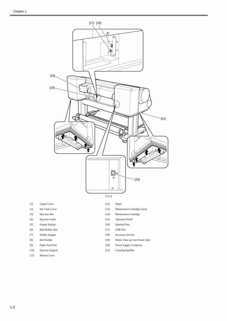
F-1-2
[1] Upper Cover [12] Stand
[2] Ink Tank Cover [13] Maintenance Cartridge Cover
[3] Ejection Slot [14] Maintenance Cartridge
[4] Ejection Guide [15] Operation Panel
[5] Output Stacker [16] Ethernet Port
[6] Roll Holder Slot [17] USB Port
[7] Holder Stopper [18] Accessory Pocket
[8] Roll Holder [19] Media Take-up Unit Power Inlet
[9] Paper Feed Slot [20] Power Supply Connector
[10] Ejection Support [21] Carrying Handles
[11] Release Lever
[17]
[18]
[19]
[20]
[16]
[21]
Chapter 1
1-3
1.2 Features
1.2.1 Features0030-4812
- Media pass in widths up to 44 inches (1117.6 mm).- Large ink tanks reduce the need for frequent ink replacement.- Uninterrupted printing from subtanks.- BK and MBK inks are loaded concurrently to eliminate the need for their replacement.- A 8-color pigment ink system "LUCIA EX" is used to improve rubfastness, chromogenic effect, and bronzing resistance, ensuring higher-grade printing.- A printing mode that improved control of the optimum ink droplet landing order (when in the mode for the highest image quality) and the ink droplet landingaccuracy ensure higher-grade printing.- A printhead having nozzles (I-shaped nozzle) with a new shape reduces ink mist, ensuring superfine printing.- The symmetrical order of the printhead's ink nozzle color reduces uneven print.- The operation panel that equipped a 160 x 128-dot large LCD allows you to operate the printer intuitively.- Media take-up unit (option) is supported.- Media take-up unit (option) can be mounted concurrently with a basket.- Durability will be added by maintenance kit.- Barcodes printed on roll media makes measuring the remaining roll length more manageable.- Borderless four-side printing support (roll media) reduces laborious cutting work, easing the job of creating posters to a significant degree.- High-speed printing with a 1-inch head for each color (1280 nozzles), under bidirectional print control.- The color calibration feature adds to the faithfulness of color reproduction.- The network interface (10Base-T/100Base-TX/1000Base-T) compatible with 1000Base-T (Gigabit Ethernet) comes standard with the printer to cope with thehigh-speed LAN environment.- Compatibility with e-maintenance/imageWARE Remote allows centralized management of customer's printer information.- The hard disk is installed for better print job management.
Functional enhancements new to this model include:- The processing ability of the printed data will enhance by increase of hard disk drive capacity.- A newly multi sensor has been able to perform a high accurate color calibration.
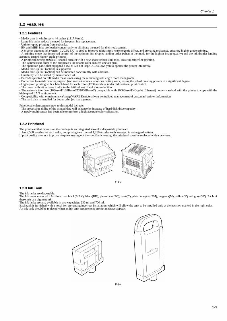
1.2.2 Printhead0013-2742
The printhead that mounts on the carriage is an integrated six-color disposable printhead.It has 2,560 nozzles for each color, comprising two rows of 1,280 nozzles each arranged in a staggerd pattern.If print quality does not improve despite carrying out the specified cleaning, the printhead must be replaced with a new one.
F-1-3
1.2.3 Ink Tank0017-8112
The ink tanks are disposable.The ink tanks come with 8-colors: mat black(MBK), black(BK), photo cyan(PC), cyan(C), photo magenta(PM), magenta(M), yellow(Y) and gray(GY). Each ofthese inks are pigment ink.The ink tanks are also available in two capacities: 330 ml and 700 ml.Each tank is furnished with a notch for preventing incorrect installation, which will allow the tank to be installed only at the position marked in the right color.An ink tank should be replaced when an ink tank replacement prompt message appears.
F-1-4

Chapter 1
1-4
1.2.4 Cutter Unit0013-6369
The cutter unit that mounts on the carriage unit is disposable.Replace the cutter unit when it gets dull.
F-1-5
1.2.5 Roll Holder0020-5421
The roller holder accepts paper tubes having inside diameters of both 2 and 3 inches. It is furnished with attachments for 2- and 3-inch diameter paper tubes.The roll holder clamps the paper tube of a roll not exceeding 150 mm in outside diameter from the inside.
F-1-6[2-inch paper tube attachment]
F-1-7[3-inch paper tube attachment 1]
F-1-8[3-inch paper tube attachment 2]
F-1-9

Chapter 1
1-5
1.2.6 Stand0017-8299
The stand is equipped with casters so that the printer can be easily moved.
F-1-10
[1] Stand [2] Stopper
O N
[2]
[1]

Chapter 1
1-6
1.2.7 Media Take-up Unit0014-8824
Media take-up unitThe Media Take-up unit spools the 2 or 3 inch core, the roll media (17" to 44"), after it is printed by the host computer.Take-up begins once the falling paper is detected by the Media take-up paper detection sensor, attached to the weight roller.The roll media may also be manually spooled, using the button on the media take up unit.The media take-up unit has an overload protection feature to prevent accidents while spooling rolls. (This feature will disable the motor automatically when anoverload occurs while spooling a roll.)
Additional features of the media take-up unit include:- An adapter may be installed to support a 3-inch paper tube.- Roll media can be unwound by feeding them backwards to visually check the images.- Weight rollers varying in length to suit specific roll widths ensure added takeup efficiency.- The printer detects errors in the media take-up unit as an independent function.- Linked with the printer's sleep mode.
F-1-11
WeightThis weight consists of weight roll(7 pcs.)[1], weight flange(2 sets)[2] and weight joint[3].
F-1-12
[1] Left media take-up unit [4] Media take-up unit[2] Rewind spool [5] 3-inch adapter[3] Media take-up sensor
[1]
[2]
[3]
[5]
[4]
[2]
[1]
[2]
[2][1]
[3]
[1]
[2]

Chapter 1
1-7
1.2.8 Hard Disk Drive0017-8472
Each print job received from the host computer is saved to the hard disk drive(serial ATA connection) attached to the printer, so the printer can print the job repeat-edly as needed, without having to wait for its retransmission from the host computer.
Saving print jobs will offer the following benefits:- Eased computer workloadA print job may be automatically preserved to the hard disk when printing or may be preserved to the hard disk without printing. A print job preserved can beprinted in as many copies as needed without having to use the host computer.
- Reprinting after error occurrenceIf the printer encounters errors, such as paper out, while printing a print job, it can resume the print operation as soon as the errors are cleared, without needing itsretransmission from the host computer.
- Higher print work efficiencyPrint jobs can be printed selectively or in a specified number of copies without using a host computer. Multiple print jobs can be printed batched. Unattended printoperations in the nighttime are also possible.
1.2.9 Consumables0026-6820
PrintheadThe consumable printhead is the same as the one that comes with the printer.
F-1-13Ink tanksThe consumable ink tanks contain 8 colors: mat black, black, photo cyan, cyan, photo magenta, magenta, yellow and gray. Each tank is available in two capacities:330 ml and 700 ml.
F-1-14Maintenance cartridgeThe consumable maintenance cartridge (including the shaft cleaner) is the same as the one that comes with the printer.
F-1-15

Chapter 1
1-8
1.3 Product Specifications
1.3.1 Product Specifications0030-4813
Type Bubble jet large-sized paper printer (stand model)Feeding system Roll media: Manual (front loading)
Cut sheet: Paper tray (front loading)Feeding capacity - Roll media
One rollOuter diameter of roll: 150 mm or less- Cut sheet1 sheet
Delivery method Forward delivery, face upSheet delivery capability 1 sheet (using the outout stacker of the stand)Cutter Automatic cross-cutter (round blade)
Type of media Plain Paper, Plain Paper (High Quality), Plain Paper (High Grade),Coated Paper, Heavyweight Coated Paper, Premium Matte Paper,Glossy Photo Paper, Semi-Glossy Photo Paper, Backlit Film, BackprintFilm, Flame-Resistant Cloth, Fine Art Photo, Fine Art HeavyweightPhoto, Fine Art Textured, Canvas Matte, Premium Coated Paper,Graphic Canvas, Durable Backlit Film, Durable Banner, Matt CoatedPaper, Extra Matt Coated Paper, Opaque Paper, Hi Res Graphic Paper,Prem Art Paper Embossed, Prem Art Paper Smooth, Hi Res BarrierPaper, Scrim Banner, Uni Opaque Backlit Film, Roll-Up Film, WaterRes Art Canvas, Adhesive Matt Vinyl Stretch
Supported thickness 0.07mm to 0.8mmMedia size (Roll media) Width: 254mm (10") to 1118mm (44")
Length: 203mm (8") to 18m (709") * Outer diameter of roll :150mm or less* The maximum amount of length may vary by the using operatingsystem or the applications.
Media size (Cut sheet) Width: 203mm (8") to 1118mm (44")Length: 203mm (8") to 1600mm (63")
Printable area (Roll media) Internal area, excluding a 5-mm top, bottom and left and right margins.* The printable area may vary with each type of paper media used.
Printable area (Cut sheet) Internal area, excluding a 5-mm top margin, a 23-mm bottom margin and5-mm left and right margins.* The printable area may vary with each type of paper media used.
Printing recommendation area (Roll media)
Internal area, excluding a 20-mm top margin, a 5-mm bottom margin and5-mm left and right margins.
Printing recommendation area (Cut sheet)
Internal area, excluding a 20-mm top margin, a 23-mm bottom marginand 5-mm left and right margins.
Borderless printing * Roll media onlywidth: 254mm(10"), 355.6mm(14"), 431.8mm(17"), 515mm(B2/B3),594mm(A1/A2), 609.6mm(24"), 841mm(A0/A1), 914.4mm(36"),1030mm(B0/B1), 1066.8mm(42"), 1117.6mm(44")
Memory 384MBIncrease of memory: none
Hard disk drive 250GB (2.5inch, 5400rpm, S-ATA I/F)Firmware Flash ROM (update from USB or Ethernet)
- Printer description languageGARO (Graphic Arts language with Raster Operation)
Emulation NoneInterface USB 2.0 Hi-speed
Network (10BASE-T/100BASE-TX/1000BASE-T)Operation panel LCD (160 X 128 dots), 13 keys, 5 LEDs
- Panel languageEnglish- Message languageEnglish, German, French, Italian, Spanish, Chinese, Korean, Russianandand Japanese
Printhead/Ink Tank type Printhead and separate ink tanksPrinthead [PF-05]
Structure: Integrated six-color assembly- Number of nozzles C, PC, PM, GY: 2,560 for each color X2- Number of nozzles BK, MBK, M, Y: 2,560 for each color
Ink tank [PFI-306/8306] BK/MBK/C/M/Y/PC/PM/GY[PFI-706/8706] BK/MBK/C/M/Y/PC/PM/GYInk type: Pigment inkInk tank capacity: [PFI-306/8306] 330 ml, [PFI-706/8706] 700 ml
Detection functions (Cover system)
Cover open/closed detection: YesLeft and right ink tank cover open/closed detection: Yes

Chapter 1
1-9
1.4 Detailed Specifications
1.4.1 Interface Specifications0023-2577
a. USB (standard) (1) Interface type USB 2.0 Hi-Speed (Full speed (12 Mbits/sec), High speed (480 Mbits/sec)) (2) Data transfer system Control transfer Bulk transfer (3) Signal level Compliant with the USB standard. (4) Interface cable Twisted-pair shielded cable, 5.0 m max. Compliant with the USB standard. Wire materials: AWG No.28, data wire pair (AWF: American Wire Gauge) AWG No.20 to No.28, power distribution wire pair (5) Interface connector Printer side: Series B receptacle compliant with USB standard Cable side: Series B plug compliant with USB standard
b. Network (standard) (1) Interface type Interface compliant with IEEE802.3 (2) Data transfer system IEEE802.0 10Base-T, IEEE802.3u 100Base-TX/Auto-Negotiation, IEEE802.3ab 1000Base-T/Auto-Negotiation, IEEE802.3x Full Duplex (3) Interface cable Category 5 (UTP or FTP) cable, 100 m or shorter Compliant with ANSI/EIA/TIA-568A or ANSI/EIA/TIA-568B (4) Interface connector Printer side: Compliant with IEEE802.3, ANSI X3.263, ISO/IEC60603-7 (5) Protocol IPX/SPX (Netware4.2(J), 5.1(J), 6.0(J)), SNMP, TCP/IP, AppleTalk, HTTP
Detection functions (Ink passage system)
Ink tank presence/absence detection: YesRemaining ink level detection: YesMaintenance cartridge presence/absence detection: YesUsed ink tank full detection: Yes
Detection functions (Carriage system)
Printhead presence/absence detection: YesCarriage position detection: YesCarriage home position detection: YesCarriage cover open/closed detection: YesCarriage temperature detection: YesPrinthead height detection: YesNon-discharging nozzle detection: YesNon-discharging nozzle backup feature: Yes
Detection functions (Paper path system)
Paper presence/absence detection: YesPaper width detection: YesSkew detection: YesPaper release lever position detection: YesRemaining roll media detection: YesFeed roller rotation detection: Yes
Operating noise Operating: Approx. 50dB (A) or lessStandby: Approx. 35dB (A) or less
Operating environment Temperature: 15 to 35 degrees centigradeHumidity: 10% to 90%RH
Print quality guaranteed environment
Temperature: 15 to 30 degrees centigradeHumidity: 10% to 80%RH
Power supply 100-240 VAC (50/60 Hz)Power consumption (Maximum) During printing: Max. 190WPower consumption In power save (sleep) mode:
100-120 VAC : 5W or less220-240 VAC : 6W or lessDuring standby: 0.5W or less
Printer unit dimensions (WxDxH)
1893mm x 975mm x 1144mm (with stand and output stacker)
Weight Approx. 143 kg (with stand and output stacker)

Chapter 1
1-10
1.5 Names and Functions of Components
1.5.1 Front0024-9417
F-1-16[1] Top Cover Open this cover to install the Printhead, load paper, and remove any jammed paper from inside the printer as needed.[2] Ink Tank Cover Open this cover to replace an Ink Tank.[3] Ejection Slot All printed matter is ejected from this port.[4] Ejection Guide Guides printed documents as they are ejected. Open this guide when loading a roll.[5] Output Stacker A cloth tray that catches ejected documents.[6] Roll Holder Slot Slide the Roll Holder into this slot.[7] Holder Stopper Secure the roll on the Roll Holder with this part.[8] Roll Holder Load the roll on this holder.[9] Paper Feed Slot When loading a roll, insert the edge of the roll paper here.[10] Ejection Support Prevents printed documents from winding around the Roll Holder or Paper Feed Slot.[11] Release Lever Releases the Paper Retainer. Lift this lever toward the front of the printer when loading paper.[12] Stand A stand that holds the printer. Equipped with casters to facilitate moving the printer.[13] Maintenance Cartridge Cover Open this cover to replace the Maintenance Cartridge.[14] Maintenance Cartridge Ink used for maintenance purposes such as head cleaning is absorbed. (Replace the cartridge when it is full.)[15] Operation Panel Use this panel to operate the printer and check the printer status.
[10]
[3]
[4]
[5]
[6] [11]
[9]
[12]
[13]
[14]
[15]
[1]
[2]
[8]
[7]
Chapter 1
1-11
1.5.2 Rear0024-9418
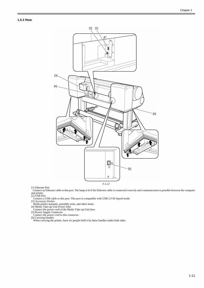
F-1-17[1] Ethernet Port Connect an Ethernet cable to this port. The lamp is lit if the Ethernet cable is connected correctly and communication is possible between the computerand printer.[2] USB Port Connect a USB cable to this port. This port is compatible with USB 2.0 Hi-Speed mode.[3] Accessory Pocket Holds printer manuals, assembly tools, and other items.[4] Media Take-up Unit Power Inlet Connect the power cord of the Media Take-up Unit here.[5] Power Supply Connector Connect the power cord to this connector.[6] Carrying handles When carrying the printer, have six people hold it by these handles under both sides.
[2]
[3]
[4]
[5]
[1]
[6]

Chapter 1
1-12
1.5.3 Top Cover (Inside)0024-9419
F-1-18[1] Top Cover Roller Prevents paper from rising when ejected.[2] Carriage Moves the Printhead. The carriage serves a key role in printing.[3] Borderless Printing Ink Grooves These grooves catch ink outside the edges of paper during borderless printing.[4] Fixed Blade The Cutter Unit passes through this blade to cut paper.[5]Platen The Printhead moves across the platen to print. The Vacuum holes on the platen hold paper in place.[6] Pinch Roller Important in supplying the paper. This retainer holds paper as it is fed.[7] Carriage Shaft The Carriage slides along this shaft.[8] Paper Alignment Line Align paper with this line when loading it.[9] Cleaning Brush When cleaning inside of the Top Cover, use this brush to sweep away paper dust on the Platen.[10] Switch Set the switch to the side opposite of the circle mark if the edges of printed images are blurred. Set the switch to the circle mark side before borderlessprinting.
[1]
[2]
[7]
[8][6]
[5][4] [3]
[9]
[10]

Chapter 1
1-13
1.5.4 Carriage0024-9420
F-1-19[1] Printhead Fixer Cover Holds the Printhead in place.[2] Printhead Equipped with ink nozzles. Printheads serve a key role in printing.[3] Carriage Cover Protects the Carriage.[4] Cutter Unit A round-bladed cutter for automatic paper cutting. The cutter blade is retracted inside when not cutting.[5] Printhead Fixer Lever Locks the Printhead Fixer Cover.[6] Shaft Cleaner Prevents the Carriage Shaft from becoming dirty.[7] Cutter Unit Detachment Lever Used when replacing the Cutter Unit.
[3]
[6]
[2]
[4]
[5]
[2][1]
[7]

Chapter 1
1-14
1.5.5 Ink Tank Cover (Inside)0026-6822
F-1-20[1] Ink Tank Cartridges of ink in each color.[2] Ink Tank Lock Lever A lever that locks the Ink Tank in place and protects it. Lift and press down the lever when replacing an Ink Tank. To open it, lift the stopper of thelever until it stops, and then push it down toward the front. To close it, push it down until it clicks into place.
F-1-21[3] Ink Lamp (Red) Indicates the state of the Ink Tank as follows when the Ink Tank Cover is opened. - On: The Ink Tank is installed correctly. - Off: No Ink Tank is installed, or the ink level detection function is off. - Flashing slowly: Not much ink is left. - Flashing rapidly: Ink tank is empty.[4] Ink Color Label Load an Ink Tank that matches the color and name on this label.
[2][1]
<Left> <Right>
[2][1]
[3] [4]

Chapter 1
1-15
1.6 Basic Operation
1.6.1 Operation Panel0024-9421
This section explains the functions of the buttons and the meanings of the LEDs on the operation panel.
F-1-22[1] Display Printer menus, statuses, and messages are shown on this display.[2] [Power] button Use this button to turn on or off the printer. When the printer is powered or in the sleep mode, the [Power] button lamp stays lit.[3] [Stop] button Use this button to stop execution of a job or drying ink.[4] [Navi] button Use this key to confirm the procedures for loading/unloading media, replacing an ink tank, and replacing the printhead.[5] Direction buttons - button: Pressing this button on the [tab selection screen] moves the tab. When a menu requiring you to enter a value is selected, pressing this button allowsyou to move to the left-hand digit. - button: Pressing this button in a menu displays the upper item or setting value. - button: Pressing this button on the [tab selection screen] moves the tab. When a menu requiring you to enter a value is selected, pressing this button allowsyou to move to the right-hand digit. - button: Pressing this button in a menu displays the lower item or setting value.[6] [OK] button Pressing this button on the [tab selection screen] displays the menu for the displayed tab. In the menu for a tab, pressing this button at the item preceded by [+] allows you to move to the bottom layer of menu items, where you can execute a menu itemor set values. Also press this button when a message asking you to press the [OK] button is shown on the display.[7] [Back] button Pressing this button displays the preceding screen.[8] [Menu] button Pressing this button displays the [tab selection screen] screen.[9] [Media Cut] button When roll media is loaded, pressing this button cuts the media.[10] [Media Feed] button When roll media is loaded, pressing this button allows you to change the media position.[11] [Media Change] button Press this button when loading/replacing media.[12] [Cut Sheet] lamp (green) This lamp stays lit when cut sheet is selected as a media type.[13] [Roll Media] lamp (green) This lamp stays lit when roll media is selected as a media type.[14] Message lamp (orange) - Stays lit: A warning message is being displayed.- Blinking: An error message is being displayed.- Not lit: The printer is normal or not powered.[15] Data reception lamp (green) - Blinking: When the printer is making prints, this lamp indicates that a print job is being received or processed. When the printer is not making prints, this lampindicates that the print job is suspended or the firmware data is being received. - Not lit: This lamp indicates that there is no print job.
MEMO:When the printer is in the sleep mode, pressing any button other than the [Power] button wakes up the printer.
[1] [2] [3]
[7]
[11]
[4]
[9]
[10]
[15] [14] [8] [5]
[6]
[12]
[13]
Chapter 1
1-16
1.6.2 Display0023-1271
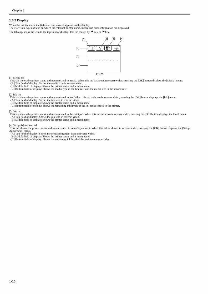
When the printer starts, the [tab selection screen] appears on the display.There are four types of tabs on which the relevant printer status, menu, and error information are displayed.The tab appears as the icon to the top field of display. The tab moves by key or key.
F-1-23[1] Media tab This tab shows the printer status and menu related to media. When this tab is shown in reverse video, pressing the [OK] button displays the [Media] menu. -[A] Top field of display: Shows the media icon in reverse video. -[B] Middle field of display: Shows the printer status and a menu name. -[C] Bottom field of display: Shows the media type in the first row and the media size in the second row.
[2] Ink tab This tab shows the printer status and menu related to ink. When this tab is shown in reverse video, pressing the [OK] button displays the [Ink] menu. -[A] Top field of display: Shows the ink icon in reverse video. -[B] Middle field of display: Shows the printer status and a menu name. -[C] Bottom field of display: Shows the remaining ink levels of the ink tanks loaded in the printer.
[3] Job tab This tab shows the printer status and menu related to the print job. When this tab is shown in reverse video, pressing the [OK] button displays the [Job] menu. -[A] Top field of display: Shows the job icon in reverse video. -[B] Middle field of display: Shows the printer status and a menu name.
[4] Setup/Adjustment tab This tab shows the printer status and menu related to setup/adjustment. When this tab is shown in reverse video, pressing the [OK] button displays the [Setup/Adjustment] menu. -[A] Top field of display: Shows the setup/adjustment icon in reverse video. -[B] Middle field of display: Shows the printer status and a menu name. -[C] Bottom field of display: Shows the remaining ink level of the maintenance cartridge.
[1]
[A]
[2] [3] [4]
[B]
[C]

Chapter 1
1-17
1.6.3 Main Menu0028-6325
The printer has a Main menu which includes a menu related to maintenance such as adjustment of ink ejection position of each nozzle and head cleaning, a menurelated to printing settings such as auto cutting and ink drying time, and a menu related to parameters such as a message language.1. Menu Operationa) Displaying menu on each tabPress the key or key on the [Tab Selection] screen to select a tab, and press the [OK] key.A menu associated with each tab is displayed. Press the key or key to select a menu and press the [OK] key. The menu is selected and menu items are displayed. Select a menu with [+] on the left side and press the [OK] key to navigate to lower level menus.
b) Setting menu itemsPress the key or key to select an item to set and press the [OK] key. The item is checked on the left side check box to confirm that it is set. After 2 seconds, the menu that is one level above is displayed.
c) Setting numeric value for a menu itemProceed as follows to set a numeric value for an item such as network settings. 1. Press the key or key to move the underscore to the field you want to enter a numeric value. 2. Press the key or key to enter a numeric value. 3. Repeat steps 1 and 2 and press the [OK] key when finished.

Chapter 1
1-18
2. Main MenuThe structure and settings of the main menu is as follows. The asterisk mark "*" is default setting.[Paper Menu]
T-1-1
First Level Second Level Third Level Fourth Level Fifth Level [Load Paper] [Roll Paper]
[Cut Sheet][Eject Paper][Chg. Paper Type] [Roll Paper] (The paper type is displayed
here.)[Cut Sheet] (The paper type is displayed
here.)[Chg. Paper Size] [Sheet Size]*2 (The paper type is displayed
here.)[CustomPaperSize] (Set the paper length and
width.)[Roll Length]*1 (Set the paper length.)[Roll Width]*2 (Set the paper width.)
[ManageRemainRoll] [Off]*[On]
[Paper Details] (The paper type is displayed here.)
[Head Height] [Automatic]*[Highest][High][Standard][Low][Lowest][Super Low]
[Skew Check Lv.] [Standard]*[Loose][Off]
[Cutting Mode] [Automatic][Eject][Manual]
[Cut Speed] [Fast][Standard][Slow]
[Trim Edge First] [Automatic][Off][On (Preset Len)][On(Input Length)][Manual]
[CutDustReduct.] [Off][On]
[VacuumStrngth] [Automatic]*[Strongest][Strong][Standard][Weak][Weakest]
[Roll Tension] [High][Standard]

Chapter 1
1-19
T-1-2
First Level Second Level Third Level Fourth Level Fifth Level [Paper Details] (The paper type is displayed
here.)[Scan Wait Time] [Dry time] [Off]
[1 sec.][3 sec.][5 sec.][7 sec.][9 sec.]
[Area]*18 [Entire area]*[Leading edge]
[Roll DryingTime] [Off][30 sec.][1 min.][3 min.][5 min.][10 min.][30 min.][60 min.]
[NearEnd RollMrgn] [5mm][20mm]
[NearEnd Sht Mrgn] [5mm][20mm]
[Bordless Oversize] [Standard]*[Little]
[Width Detection] [Off][On]*
[Return Defaults][Paper Details][Keep Paper Type] [Off]*
[On]
Chapter 1
1-20
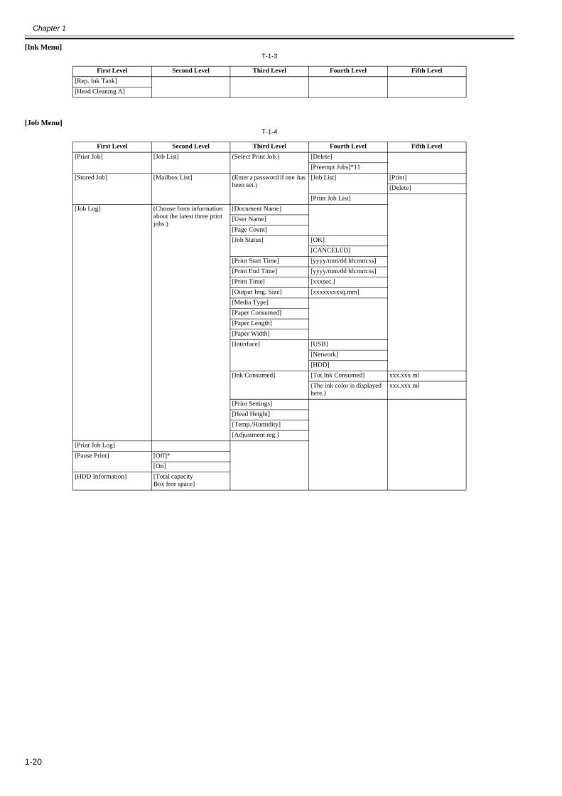
[Ink Menu]T-1-3
[Job Menu]T-1-4
First Level Second Level Third Level Fourth Level Fifth Level [Rep. Ink Tank][Head Cleaning A]
First Level Second Level Third Level Fourth Level Fifth Level [Print Job] [Job List] (Select Print Job.) [Delete]
[Preempt Jobs]*11[Stored Job] [Mailbox List] (Enter a password if one has
been set.)[Job List] [Print]
[Delete][Print Job List]
[Job Log] (Choose from information about the latest three print jobs.)
[Document Name][User Name][Page Count][Job Status] [OK]
[CANCELED][Print Start Time] [yyyy/mm/dd hh:mm:ss][Print End Time] [yyyy/mm/dd hh:mm:ss][Print Time] [xxxsec.][Output Img. Size] [xxxxxxxxsq.mm][Media Type][Paper Consumed][Paper Length][Paper Width][Interface] [USB]
[Network][HDD]
[Ink Consumed] [Tot.Ink Consumed] xxx.xxx ml(The ink color is displayed here.)
xxx.xxx ml
[Print Settings][Head Height][Temp./Humidity][Adjustment reg.]
[Print Job Log][Pause Print] [Off]*
[On][HDD Information] [Total capacity
Box free space]

Chapter 1
1-21
[Set./Adj. Menu]T-1-5
First Level Second Level Third Level Fourth Level Fifth Level [Test Print] [Nozzle Check]
[Status Print][Interface Print][Paper Details][Print Job Log][Menu Map]
[Adjust Printer] [Head Posi. Adj.] [Standard][Simple][Other] [Initial adjustmt]
[Manual][Feed Priority] [Adj. Priority]*6 [Automatic]*
[Print Quality][Print Length]
[Adj. Quality]*4*6 [Auto(GenuinePpr)][Auto(OtherPaper)][Manual]
[Adjust Length]*5*6 [AdjustmentPrint] [A:High][B:Standard/Draft]
[Change Settings] [A:High][B:Standard/Draft]
[Calibration] [Auto Adjust][Calibration Log] [Date]
[Paper Type][Adjustment Type]
[Use Adj. Value] [Disable][Enable]*
[Set Exec. Guide] [Off]*[On]
[Return Defaults][Maintenance] [Head Cleaning] [Head Cleaning A]
[Head Cleaning B][Nozzle Check][Replace P.head] [Printhead L]
[Printhead R][L & R Printheads]
[Repl. maint cart][Repl. S. Cleaner][Change Cutter]
[Interface Setup] [EOP Timer]*12 [10 sec.][30 sec.][1 min.][2 min.][5 min.][10 min.]*[30 min.][60 min.]

Chapter 1
1-22
T-1-6
First Level Second Level Third Level Fourth Level Fifth Level Sixth Level Seventh Level
[Interface Setup] [TCP/IP]*12 [IPv4] [IPv4 Mode] [Automatic][Manual]*
[Protocol]*7 [DHCP] [On][Off]*
[BOOTP] [On][Off]*
[RARP] [On][Off]*
[IPv4 Settings]*13 [IP Address] xxx.xxx.xxx.xxx[Subnet Mask] xxx.xxx.xxx.xxx[Default G/W] xxx.xxx.xxx.xxx
[DNS Settings]*13 [DNS Dync update] [On][Off]*
[Pri. DNS SrvAddr][Sec. DNS SrvAddr][DNS Host Name][DNS Domain Name]
[IPv6] [IPv6 Support] [On][Off]*
[IPv6 StlessAddrs]*9 [On]*[Off]
[DHCPv6]*9 [On][Off]*
[DNS Settings]*9*13 [DNS Dync update] [Statefull Addr] [On][Off]*
[Stateless Addr] [On][Off]*
[Pri. DNS SrvAddr][Sec. DNS SrvAddr][DNS Host Name][DNS Domain Name]
[NetWare]*12 [NetWare] [On][Off]*
[Frame Type]*8 [Auto Detect][Ethernet 2][Ethernet 802.2]*[Ethernet 802.3][Ethernet SNAP]
[Print Service]*8 [BinderyPServer][RPrinter][NDSPServer][NPrinter]

Chapter 1
1-23
T-1-7
First Level Second Level Third Level Fourth Level Fifth Level [Interface Setup] [AppleTalk]*12 [On]
[Off]*[Ethernet Driver]*12 [Auto Detect] [On]*
[Off][Comm.Mode]*10 [Half Duplex]*
[Full Duplex][Ethernet Type]*10 [10Base-T]*
[100Base-TX][1000Base-T]
[Spanning Tree] [Not Use]*[Use]
[MAC Address] xxxxxxxxxxxx[Interface Print]*12[Return Defaults]*12
[System Setup] [Sleep Timer]*19 [5 min.]*[10 min.][15 min.][20 min.][30 min.][40 min.][50 min.][60 min.][210 min.]
[Shut Down Timer] [off][5 min.][10 min.][30 min.][1 hour][4 hours][8 hours][12 hours]
[Buzzer] [Off][On]*
[Contrast Adj.] -4,-3,-2,-1,0*,+1,+2,+3,+4[Date & Time]*12 [Date] [yyyy/mm/dd]*14
[Time] [hh:mm][Date Format]*12 [yyyy/mm/dd]*
[dd/mm/yyyy][mm/dd/yyyy]
[Language] [English][Japanese][Francais][Italiano][Deutsch][Espanol][Russian][Chinese] (simplified)[Korean]
Chapter 1
1-24
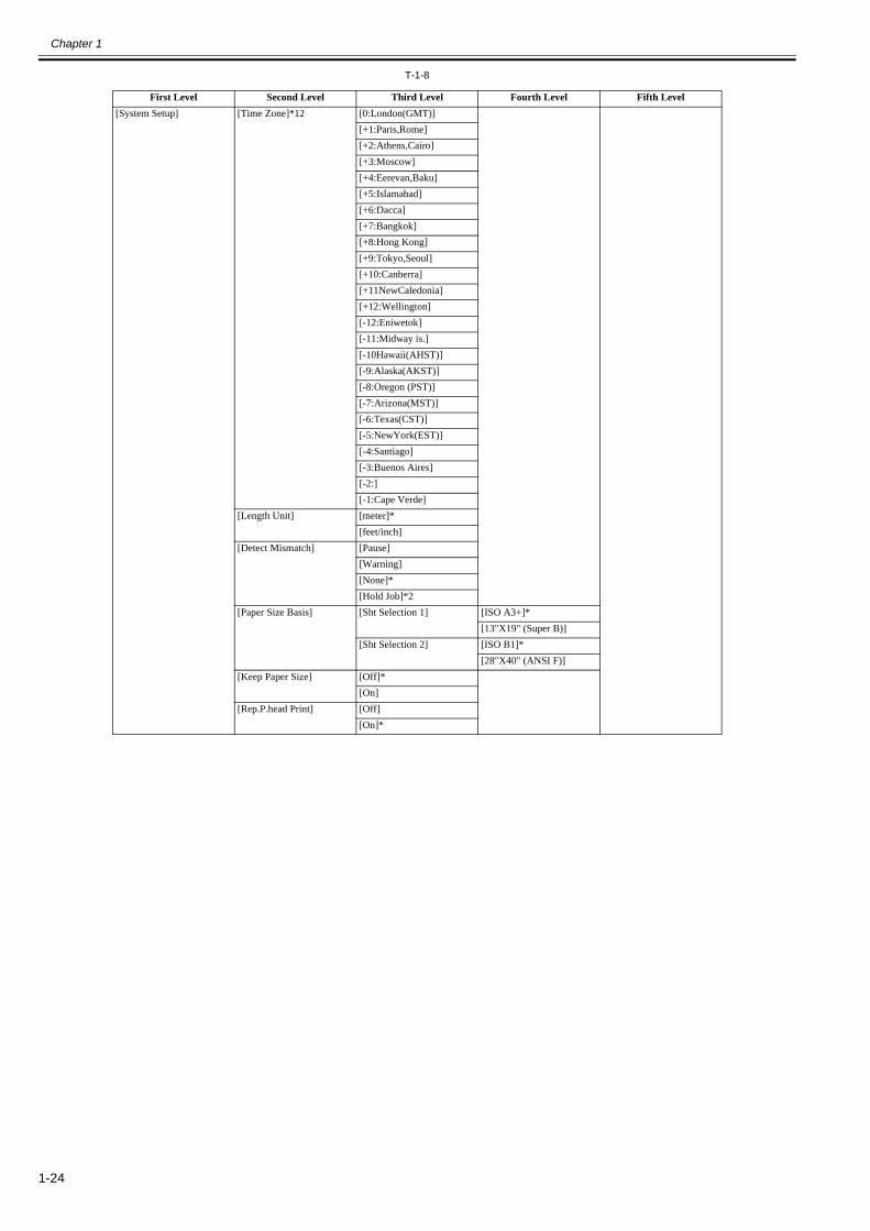
T-1-8
First Level Second Level Third Level Fourth Level Fifth Level [System Setup] [Time Zone]*12 [0:London(GMT)]
[+1:Paris,Rome][+2:Athens,Cairo][+3:Moscow][+4:Eerevan,Baku][+5:Islamabad][+6:Dacca][+7:Bangkok][+8:Hong Kong][+9:Tokyo,Seoul][+10:Canberra][+11NewCaledonia][+12:Wellington][-12:Eniwetok][-11:Midway is.][-10Hawaii(AHST)][-9:Alaska(AKST)][-8:Oregon (PST)][-7:Arizona(MST)][-6:Texas(CST)][-5:NewYork(EST)][-4:Santiago][-3:Buenos Aires][-2:][-1:Cape Verde]
[Length Unit] [meter]*[feet/inch]
[Detect Mismatch] [Pause][Warning][None]*[Hold Job]*2
[Paper Size Basis] [Sht Selection 1] [ISO A3+]*[13"X19" (Super B)]
[Sht Selection 2] [ISO B1]*[28"X40" (ANSI F)]
[Keep Paper Size] [Off]*[On]
[Rep.P.head Print] [Off][On]*

Chapter 1
1-25
T-1-9
*1: Available only if ManageRemainRoll is On.*2: Available only if Width Detection is set to Off.*3: Available after Auto(Advanced) in Head Posi. Adj. has been used once.*4: Available when you have specified Feed Priority > Adj. Priority > Automatic or Print Quality.*5: Available when you have specified Feed Priority > Adj. Priority > Automatic or Print Length.*6: Displayed if a sheet is loaded in the printer.*7: Not shown if you have set IPv4 Mode to Manual.*8: Not shown if you have set NetWare to Off.*9: Not displayed if IPv6 Support is Off.*10: Not shown if you have set Auto Detect to On.*11: Print Anyway is displayed when a job being held is selected.*12: Viewing and configuration is possible for administrators, and only viewing for other users.*13: Viewing and configuration is possible for administrators only.*14: Follows the setting in Date Format.*15: Displayed only when the Media Take-up Unit is attached.*16: Available if: Use Take-up Reel is Enable, roll paper is loaded, and you have not executed Auto Feed for the loaded roll.*17: Available when Use Take-up Reel is Enable.*18: Leading edge is not available as a setting option in the Paper Detailed Settings dialog box of the printer driver.*19: Default setting for the time to enter the power save mode/sleep mode is recommended.
First Level Second Level Third Level Fourth Level Fifth Level [System Setup] [Nozzle Check] [Frequency] [Standard]*
[1 page][10 pages][Off]
[Warning] [Off]*[On]
[CarriageScanWidth] [Automatic]*[Fixed]
[Use RemoteUI]*12 [On]*[Off]
[Reset PaprSetngs]*12[Erase HDD Data]*12 [High Speed]
[Secure High Spd.][Secure]
[Output Method] [Print]*[Print (Auto Del)][Save: Box XX]
[Print After Recv] [Off]*[On]
[Common Box Set.]*12 [Print][Print (Auto Del)]*
[Show Job Log] [Off][On]*
[Take-up Reel] [Use Take-up Reel] [Disable]*[Enable]
[Auto Feed]*16[Skip Take-up Err]*17 [Off]*
[On][Prep.MovePrinter] [Level 1]
[Level 2][Level 3]
[Admin. Menu]*12 [Change Password]*13 (The screen for setting the password is displayed)
[Init.Admin.Pswd]*13[Printer Info] [Paper Info]
[Ink Info][Head Info][System Info][Error Log][Other Counter]

Chapter 1
1-26
3. Main menu during printing The structure of the main menu during printing is as follows.
T-1-10
First Level Second Level Third Level Fourth Level Fifth Level [Adj. Fine Feed][Printer Info] [Paper Info]
[Ink Info][Head Info][System Info][Error Log][Other Counter]

Chapter 1
1-27
4. Main Menu SettingsMain menu items are described in the following tables.
[Paper Menu]T-1-11
Setting Item Description/Instructions [Load Paper] Select either roll paper or cut sheet.[Eject Paper] Choose this item before removing loaded paper.[Chg. Paper Type] Change currently set paper type.[Chg. Paper Size] Change currently set paper size.[ManageRemainRoll] Choose On to print a barcode at the end of a roll before you remove it. The printed barcode can
be used in managing the amount of roll paper left. ChooseOff if you prefer not to print the barcode.
[Paper Details](The paper type is displayed here.)
[Head Height] Adjust the Printhead height. [Skew Check Lv.] If you print on the paper that has an irregular width, choose Loose for a higher skew detection
threshold, or choose Off to disable skew detection. However, if paper is loaded askew when detection is Off, note that paper jams or Platen soiling may occur.
[Cutting Mode] Select whether to use standard round blade cutter or not.Select [Automatic] to cut paper after printing. Select [Manual] to print a line at the cut position after printing without cutting. Select [Eject] to prevent the printout from dropping until the ink dries after printing.
[Cut Speed] Choose the cutting speed. If you use adhesive paper, choosing Slow helps prevent adhesive from sticking to the cutter and keeps the cutter sharp.
[Trim Edge First] If a roll is loaded, the end of the paper will be cut.[CutDustReduct.] Choose On to reduce the amount of debris generated when cutting film and similar media by
printing a line at the cut position. This option reduces the amount of debris given off after cutting. It also helps prevent adhesive from sticking to the cutter and keeps the cutter sharp if you use adhesive paper.
[VacuumStrngth] Specify the level of suction that holds paper against the Platen. [Roll Tension] Choose the back tension of the roll media.[Scan Wait Time] Specify the time to wait for the ink to dry between each scan in bidirectional printing, in
consideration of how quickly the ink dries. Note that printing will take longer if you specify a wait time.
[Roll DryingTime] Specify the time to wait for the ink to dry for each sheet.[NearEnd RollMrgn] Specify the minimum margin at the leading edge of roll paper to ensure better printing quality
at the leading edge.Note that if you choose 5mm, it may lower the printing quality at the leading edge and affect feeding accuracy. The printed surface may be scratched, and ink may adhere to the leading edge. It may also cause the Platen to become soiled.
[NearEnd Sht Mrgn] Specify a margin at the leading edge of sheets to ensure better printing quality at the leading edge.Note that if you choose 5mm, it may lower the printing quality at the leading edge and affect feeding accuracy. The printed surface may be scratched, and ink may adhere to the leading edge.
[Bordless Oversize] Choose the margin during borderless printing.[Width Detection] Make this setting when the print size is different from the media size, for example, when you
want to make a print within a frame. When you select [OFF], the paper width is not detected.
[Return Defaults] Choose OK to restore Paper Details to the factory default values.[Print Paper Detail] Print the paper settings set with [Paper Details].[Keep Paper Type] Select [On] to continue using the same type of paper.

Chapter 1
1-28
[Ink Menu]T-1-12
[Job Menu]T-1-13
Setting Item Description/Instructions [Rep. Ink Tank] When replacing the Ink Tank, choose Yes and follow the instructions on the screen. [Head Cleaning A] Specify Printhead cleaning options.
Execute Head Cleaning A if printing is faint, oddly colored, or contains foreign substances.
Setting Item Description/Instructions [Print Job] [Job List] (Select Print
Job.)[Delete] Delete the current job or queued jobs.[Preempt Jobs] Print the job first after the current print job is finished printing.
[Stored Job] [Mailbox List] (Enter a password if one has been set.)
[Job List]-[Print]
Prints a saved job.
[Job List]-[Delete]
Deletes a saved job.
[Print Job List] Prints a list of saved jobs.[Job Log] (Choose from
information about the latest three print jobs.)
[Document Name] Indicates the document name of the selected print job.[User Name] Indicates the name of the user who sent the print job.[Page Count] Indicates the number of pages in the job.[Job Status] Indicates the printing results.[Print Start Time] Indicates when the print job was started.[Print End Time] Indicates when the print job was finished.[Print Time] Indicates the time required to print the job.[Output Img. Size] Indicates the image size in the print job.[Media Type] Indicates the type of paper in the print job.[Paper Consumed] Indicates the consumption of paper.[Paper Length] Indicates the length of paper.[Paper Width] Indicates the width of paper.[Interface] Indicates the interface used for the print job.[Ink Consumed] Indicates a rough estimate of how much ink was consumed per job.[Print Settings] A counter for maintenance purposes. Indicates the job print settings.[Head Height] A counter for maintenance purposes. Indicates the head height when jobs were printed.[Temp./Humidity] A counter for maintenance purposes. Indicates the temperature and humidity when jobs were
printed.[Adjustment reg.] A counter for maintenance purposes. Indicates the adjustment conditions applied to jobs.
[Print Job Log] Print the print job information such as paper type, size, and ink consumption. Ink consumption is the approximate amount of ink used to print one sheet.
[Pause Print] Select [On] to stop printing.[HDD Information] Indicates the total hard disk capacity and the mail box free space.

Chapter 1
1-29
[Set./Adj. Menu]T-1-14
Setting Item Description/Instructions [Test Print] [Nozzle Check] Print a nozzle check pattern.
[Status Print] Print the printer information.[Interface Print] Print the interface settings.[Paper Details] Prints the paper settings set with [Paper Details].[Print Job Log] Print print job information such as paper type, size, and ink consumption. Ink consumption is
the approximate amount of ink used to print one sheet.[Menu Map] Print the menu list.
[Adjust Printer]
[Head Posi. Adj.] The printer prints and reads a test pattern for automatic or manual adjustment of Printhead alignment relative to the printing direction.
[Feed Priority] [Adj. Priority] [Automatic] Set the priority feed precision. Normally select [Automatic]. Select [Print Quality] to print at high quality. Select [Print Quality] to reduce horizontal streaks. Select [Print Length] to accurately control the feed amount. However, selecting [Print Length] may cause colors to become slightly uneven in the carriage scan direction.
[Print Quality][Print Length]
[Adj. Quality] [Auto(GenuinePpr)]
Set when using paper described in the paper reference guide.A pattern to adjust the paper feed amount is printed, and the feed amount is automatically adjusted from the printed result.
[Auto(OtherPaper)]
Set when using paper not described in the paper reference guide.A pattern to adjust the paper feed amount is printed, and the feed amount is automatically adjusted from the printed result.This takes longer than [Auto (GenuinePpr)] to print and consumes more ink.
[Manual] Select for paper that cannot be adjusted by [Auto(GenuinePpr)] or [Auto(OtherPaper)], such as highly transparent paper.Print a pattern to adjust the paper feed amount according to the type of paper.
[Adjust Length]
[AdjustmentPrint]-[A:High]/[B:Standard/Draft]
Print a test pattern for adjustment relative to paper stretching or shrinkage, after which you can enter the amount of adjustment.
[Change Settings]-[A:High]/[B:Standard/Draft]
Displayed when [Print Length] is selected as [Adj. Priority] for [Feed Priority].Adjust the expansion rate of the currently loaded paper.Enter the result adjusted with [AdjustmentPrint] or the difference with your own measurement in %.Increase the adjustment value to increase the feed amount for paper that tends to expand, and reduce it for paper that tends to shrink.
[Calibration] [Auto Adjust] Choose Yes for automatic adjustment of the adjustment value after a test pattern for color calibration is printed. The new color calibration adjustment value is applied in all print jobs.
[Calibration Log] Check the date when color calibration was executed, as well as the type of paper used, as shown on the Display Screen.
[Use Adj. Value] Choose Disabled >OK if you prefer not to apply the color calibration adjustment value in print jobs. The printer driver settings will be used instead.Choose Enabled >OK to apply the color calibration adjustment value in print jobs. However, printer driver settings are given priority.
[Set Exec. Guide] Choose On if you want to be displayed the message at the recommended timing of the calibration.
[Return Defaults] Clear the color calibration adjustment value and the execution log.[Maintenance] [Head Cleaning] Specify Printhead cleaning options.
Choose Head Cleaning A if printing is faint, oddly colored, or contains foreign substances.Choose Head Cleaning B if no ink is printed at all, or if printing is not improved by Head Cleaning A.
[Nozzle Check] Print a nozzle check pattern.[Replace P.head] Not displayed during a warning message that the remaining Maintenance Cartridge capacity is
low.When replacing the Printhead, choose Yes and follow the instructions on the screen.
[Repl. maint cart] When exchanging the maintenance cartridge, choose Yes and follow the instructions on the screen.
[Repl. S. Cleaner] When replacing the Shaft Cleaner, choose Yes and follow the instructions on the screen. [Change Cutter] When transferring the printer to another location, choose the level of transfer and follow the
instructions on the screen.

Chapter 1
1-30
T-1-15
Setting Item Description/Instructions [Interface Setup]
[EOP Timer] Specify the timeout period before cancellation of print jobs that cannot be received by the printer.
[TCP/IP] [IPv4] [IPv4 Mode] Choose whether the printer IP address is configured automatically or a static IP address is entered manually.
[Protocol] [DHCP]/[BOOTP]/[RARP]
Specify the protocol used to configure the IP address automatically.
[IPv4 Settings] [IP Address]/[Subnet Mask]/[Default G/W]
Specify the printer network information when using a static IP address.Enter the IP address assigned to the printer, as well as the network subnet mask and default gateway.
[DNS Settings] [DNS Dync update]
Specify whether DNS server registration is updated automatically.
[Pri. DNS SrvAddr]/[Sec. DNS SrvAddr]
Specify the DNS server address.
[DNS Host Name]
Specify the DNS host name.
[DNS Domain Name]
Specify the DNS domain name.
[IPv6] [IPv6 Support] Set whether to support IPv6 connection.[IPv6 StlessAddrs] Set whether to use IPv6 stateless address.[DHCPv6] Set whether to use DHCPv6 setting.[DNS Settings] [DNS Dync
update]-[Statefull Addr]/[Stateless Addr]
Specify whether DNS server registration is updated automatically.
[Pri. DNS SrvAddr]/[Sec. DNS SrvAddr]
Specify the DNS server address.
[DNS Host Name]
Specify the DNS host name.
[DNS Domain Name]
Specify the DNS domain name.
[NetWare] [NetWare] Specify the NetWare protocol. To apply your changes, choose Register Setting.[Frame Type] Specify the frame type to use.[Print Service] Choose the print service.
[AppleTalk] Specify whether to use the AppleTalk protocol. To apply your changes, choose Register Setting.
[Ethernet Driver]*12
[Auto Detect] Specify the communication method. To apply your changes, choose Register Setting.Choose On for automatic configuration of the LAN communication protocol. Choose Off to use settings values of Comm.Mode and Ethernet Type.
[Comm.Mode] Choose the LAN communication method.[Ethernet Type] Choose the LAN transfer rate.[Spanning Tree] Choose whether spanning-tree packets are supported over the LAN.[MAC Address] Displays the MAC address.
[Interface Print] Print the interface settings.[Return Defaults] Select [OK] to return the [Interface Setup] settings to factory default.

Chapter 1
1-31
T-1-16
Setting Item Description/Instructions [System Setup] [Sleep Timer] Specify the period before the printer enters Sleep mode.
[Shut Down Timer] Specify the period before the printer shuts down.[Buzzer] Set the buzzer. Choose On for the buzzer to sound once for warnings and three times for errors.[Contrast Adj.] Adjust the Display Screen contrast level.[Date & Time] [Date] Set the current date.
[Time] Set the current time. This can be set only when [Date] is set.[Date Format] Specify the date format.[Language] Specify the language used on the Display Screen.[Time Zone] Specify the time zone. Time zone options indicate a main city in this time zone and the
difference from Greenwich Mean Time.[Length Unit] Choose the unit of measurement when roll length is displayed. You can switch the unit
displayed for the remaining paper amount.[Detect Mismatch] Set the printing behavior when the paper type and size set with the printer menu does not match
the paper type and size set with the printer driver. Select [Pause] to pause printing. Select [Warning] to print a warning and continue printing. Select [None] to continue printing without displaying a warning. Select [Hold Job] to queue the job with different paper type and size in a job queue on the hard disk.
[Paper Size Basis]
[Sht Selection 1] Select which size is to be recognized, [ISO A3+] or [13"x19"(Super B)], when the detected size of the cut sheet is between these sizes.
[Sht Selection 2] Select which size is to be recognized, [ISO B1] or [28"x40"(ANSI F)], when the detected size of the cut sheet is between these sizes.
[Keep Paper Size] Select [On] to give priority to paper size. If the margin set with the printer driver is less than the margin set with the printer menu, the margin set with the printer menu has priority and text and images extending beyond the margins are truncated. Select [Off] to give priority to margin settings. If the margins set with the printer driver and the margins set with the printer menu are different, the larger settings are used for printing.
[Rep.P.head Print] Select [On] to automatically perform [Adjust Detail] after replacing the Printhead.[Nozzle Check] Set with [Frequency] the timing to check for nozzle clogging after printing. Select [Standard]
to adjust the checking timing according to the nozzle usage. Select [1 page] or [10 pages] to check every one page or 10 pages.Select [On] for [Warning] to display a warning when the print head nozzle is clogged while printing.
[Use RemoteUI] Select [Off] to disable access from RemoteUI and enable setting only from the operation panel.[Reset PaprSetngs] Restores settings that you have changed with Media Configuration Tool to the factory default
values.

Chapter 1
1-32
T-1-17
Setting Item Description/Instructions [System Setup] [Erase HDD
Data][High Speed] Delete the file management information of the saved data in the HDD.[Secure High Spd.]
Overwrite the random data in the whole of the hard disk drive.
[Secure] Overwrite 00 and FF and random data in the whole of the hard disk drive once at a time. Execute the verify check whether the data has written correctly to the hard disk drive.
[Output Method] [Print] Select the output method of jobs sent from software other than the printer driver. This can be set from the printer if you are using a printer driver. Select [Print] to print normally. Select [Print (AutoDel)] to print and delete the data in hard disk. Select [Save: Box XX] to save to box without printing.
[Print (Auto Del)][Save: Box XX]
[Print After Recv] Setting of jobs sent from software other than the printer driver. This can be set from the printer if you are using a printer driver. Select [On] to print after saving.
[Common Box Set.] Select [Print(AutoDel)] to print without saving to a common box.[Show Job Log] Selecting Off prevents display of the log in Job Menu > Job Log. Additionally, the log is not
printed if you choose Job Menu > Print Job Log. Note that because job logs are not collected, the Status Monitor accounting functions will not work correctly.
[Take-up Reel] [Use Take-up Reel] Choose Enable to use the Media Take-up Unit.[Auto Feed] This command is available only if Take-up Reel is set to Enable. Choose Yes to advance roll
paper automatically on the Rewind Spool, up to the fastening position.[Skip Take-Up Err] Choose On to continue with printing even if an error occurs with the Media Take-up Unit.
Choose Off to have the printer pause before printing if a rewinding error occurs.[Prep.MovePrinter]
[Level 1] Select when moving the printer. Follow the instruction on the screen and perform the necessary process. This is not displayed when displaying a warning message about the amount remaining maintenance cartridge.
[Level 2][Level 3]
[Admin. Menu] [Change Password] Set a password to restrict displaying/setting of menus as follows. Allowed value is from 0 to 9999999.- Allow only administrator to display/set[IPv4][Change Password][Init.Admin.Pswd]- Allow administrator to display/set and non-administrator to display only[Interface Setup](exclude [IPv4])[Date & Time][Date Format][Time Zone][Use RemoteUI][Reset PaprSetngs][Save: Shared Box]
[Init.Admin.Pswd] Press [OK] to return the [Administrator Menu] password to factory default.[Printer Info] [Paper Info] Indicates the current paper size, type, and related printer settings.
[Ink Info] Indicates ink levels and maintenance cartridge capacity.[Head Info] Indicates information about the printhead.[System Info] Indicates the firmware version, serial number, and interface information.[Error Log] Indicates the most recent error messages (up to five).[Other Counter] Indicates the total printing volume of the printer.

Chapter 1
1-33
1.6.4 Basket Unit0017-9389
The Basket Unit(output stacker) can be installed at four positions, as shown.
F-1-24
F-1-25[1] When storing printed documents on the Output Stacker, set it to this position.[2] When the Output Stacker is not used, set it to this position.[3] When printing on large and stiff sheets, or when the Media Take-up Unit is used, or when the Output Stacker is stored for long periods, lower it tothis position for storage.When using the Output Stacker again after storage, reattach the Basket Rod on the front of the Output Stacker to the tips of the left and right BasketRods and pull the side rods out completely.[4] When printing banners or when printing on delicate paper, set it to this position.
- When storing printed documents on the Output Stacker, always use it in position [1]. If you do not, printed documents may not be dropped into the Output Stacker,and the printed surface may become soiled.- The Output Stacker can hold one sheet. When printing multiple pages, remove each sheet after it is printed.- Before using the Output Stacker, remove the Rewind Spool. If you do not, it may prevent printed documents from being held correctly, and it they may bescratched.
a. Using the Output Stacker in the position for ejection in the front of the printerYou can also set the Output Stacker to the following position when printing banners or when printing on delicate paper.
MEMO:- Always choose [Cutting Mode] > [Eject] in the main menu when the Output Stacker is in the position for ejection in the front of the printer. If you choose [Auto-matic], printed documents may be damaged.- During ejection in the front of the printer, be especially careful when using delicate paper or paper that curls easily.- With some types of paper, the leading edge may curl or bend during ejection. In this case, straighten out the paper. Printed documents may be damaged if the paperis curled or bent.- Some types of paper may get caught between the Ejection Guide and Output Stacker during ejection. In this case, free the paper from where it is caught. Printeddocuments may be damaged if the paper gets caught.
[2]
[3]
[1]
[4]
[3]
[1][2]
[4]

Chapter 1
1-34
1) Lift the Basket Rod gently to release the lock, lower the stacker toward the front, and push it all the way back.
F-1-262) Remove the front Basket Rod from the left and right Basket Rods, and remove the back Basket Rod and the black cord from the Rod Holder.
F-1-27

Chapter 1
1-35
3) Store the left and right Basket Rods. Next, remove the Rod Holder Adapter, leaving the Rod Holder attached, and put it in front of the printer.
F-1-284) Pull out the Basket Hooks from the left and right side of the Ejection Guide.
F-1-295) Attach the Basket Rod to the Basket Hooks so that the white tag of the Basket Cloth is on the left side.
F-1-30

Chapter 1
1-36
6) Form the Basket Cloth into a sloping shape to make it taut, and attach the middle Basket Rod to the Rod Holder.
F-1-31
b. Stowing the Output StackerStow the Output Stacker if you will use the Media Take-up Unit or if you will not use the Output Stacker for an extended period.
1) Lift the front Basket Rod gently to release the lock, lower the stacker toward the front, and push it all the way back.
F-1-32

Chapter 1
1-37
2) Remove the front Basket Rod from the left and right Basket Rods. Roll up the Basket Cloth and put it at the back of the Bottom Stand Stay.
F-1-33
F-1-34
Arrange the Basket Cloth and Basket Rod so they do not interfere with the Media Take-up Sensor.
F-1-35

Chapter 1
1-38
3) Push in the left and right Basket Rods toward the back all the way, until they stop.
F-1-36
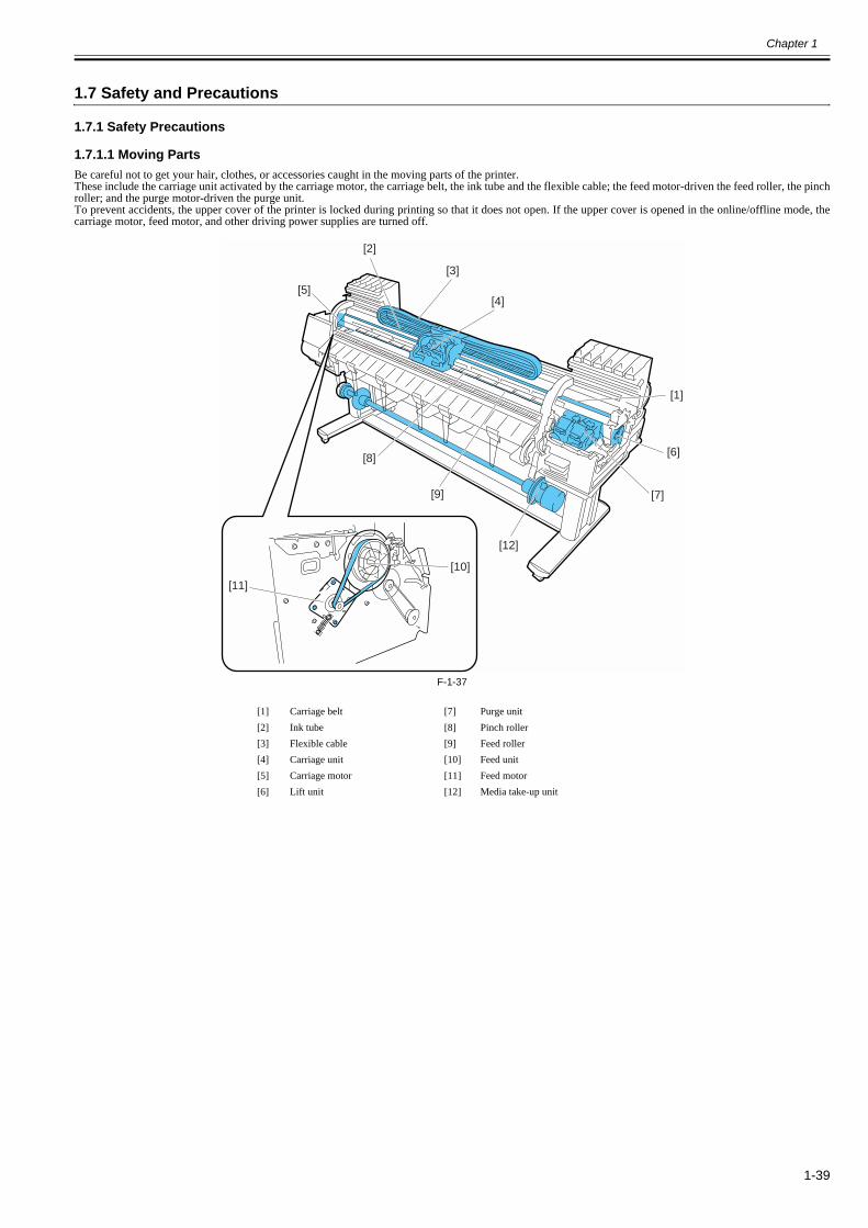
Chapter 1
1-39
1.7 Safety and Precautions
1.7.1 Safety Precautions
1.7.1.1 Moving Parts0012-6284
Be careful not to get your hair, clothes, or accessories caught in the moving parts of the printer.These include the carriage unit activated by the carriage motor, the carriage belt, the ink tube and the flexible cable; the feed motor-driven the feed roller, the pinchroller; and the purge motor-driven the purge unit.To prevent accidents, the upper cover of the printer is locked during printing so that it does not open. If the upper cover is opened in the online/offline mode, thecarriage motor, feed motor, and other driving power supplies are turned off.
F-1-37
[1] Carriage belt [7] Purge unit[2] Ink tube [8] Pinch roller[3] Flexible cable [9] Feed roller[4] Carriage unit [10] Feed unit[5] Carriage motor [11] Feed motor[6] Lift unit [12] Media take-up unit
[1]
[6]
[2]
[7]
[3]
[4][5]
[12]
[10]
[11]
[8]
[9]

Chapter 1
1-40
1.7.1.2 Adhesion of Ink0014-0264
1. Ink passagesBe careful not to touch the ink passages of the printer or to allow ink to stain the workbench, hands, clothes or the printer under repair.The ink flows through the ink tank unit, carriage unit, purge unit, maintenance-jet tray, borderless print ink groove, maintenance cartridge and the ink tubes thatrelay ink to each unit.
F-1-38
Although the ink is not harmful to the human body, it contains organic solvents.Avoid getting the ink in your mouth or eyes.Flush well with water and see a doctor if contact occurs.In case of accidental ingestion of a large quantity, call a doctor immediately.
Since this ink contains pigment, stains will not come out of clothing.
[1] Maintenance-jet tray [4] Carriage unit[2] Maintenance cartridge [5] Ink tank unit[3] Purge unit [6] Borderless print ink groove
[1]
[2]
[3]
[4]
[5]
[6]
[1]

Chapter 1
1-41
2. Ink mistSince the printhead prints by squirting ink onto the media, a minute amount of ink mist is generated in the printing unit during printing. The ink mist is collectedin the printer by the airflow. However, uncollected ink mist may stain the platen unit, carriage unit, main rail unit, external unit, or purge unit.These stains may soil the print media or hands and clothes when servicing the printer, wipe them off carefully with a soft, well-wrung damp cloth.
F-1-39
[1] Purge unit[2] Upper cover[3] Platen unit/Carriage unit/Main rail unit
[1]
[2]
[3]
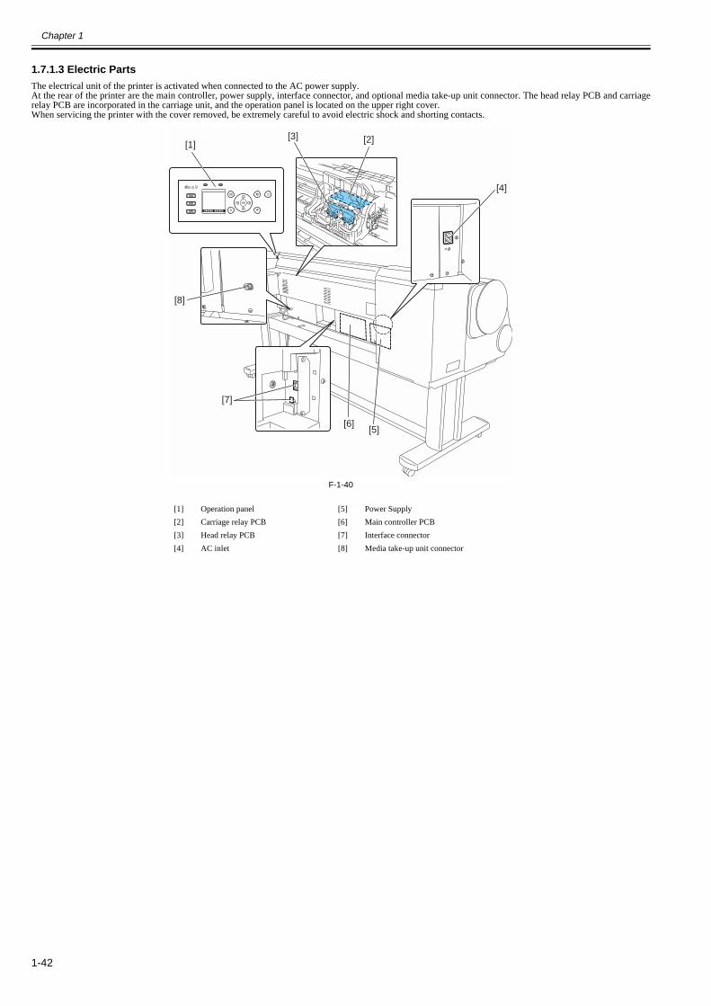
Chapter 1
1-42
1.7.1.3 Electric Parts0012-6287
The electrical unit of the printer is activated when connected to the AC power supply.At the rear of the printer are the main controller, power supply, interface connector, and optional media take-up unit connector. The head relay PCB and carriagerelay PCB are incorporated in the carriage unit, and the operation panel is located on the upper right cover.When servicing the printer with the cover removed, be extremely careful to avoid electric shock and shorting contacts.
F-1-40
[1] Operation panel [5] Power Supply[2] Carriage relay PCB [6] Main controller PCB[3] Head relay PCB [7] Interface connector[4] AC inlet [8] Media take-up unit connector
[1]
[8]
[7]
[6][5]
[4]
[2][3]
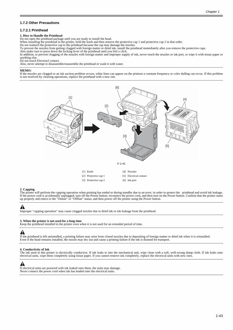
Chapter 1
1-43
1.7.2 Other Precautions
1.7.2.1 Printhead0013-1937
1. How to Handle the PrintheadDo not open the printhead package until you are ready to install the head.When installing the printhead in the printer, hold the knob and then remove the protective cap 1 and protective cap 2 in that order.Do not reattach the protective cap to the printhead because the cap may damage the nozzles.To prevent the nozzles from getting clogged with foreign matter or dried ink, install the printhead immediately after you remove the protective caps.Also make sure to press down the locking lever of the printhead until you feel a click.In addition, to prevent clogging of the nozzles with foreign matter and improper supply of ink, never touch the nozzles or ink port, or wipe it with tissue paper oranything else.Do not touch Electriacl contact.Also, never attempt to disassemble/reassemble the printhead or wash it with water.
MEMO:If the nozzles are clogged or an ink suction problem occurs, white lines can appear on the printout a constant frequency or color dulling can occur. If this problemis not resolved by cleaning operations, replace the printhead with a new one.
F-1-41
2. CappingThe printer will perform the capping operation when printing has ended or during standby due to an error, in order to protect the printhead and avoid ink leakage.If the power cord is accidentally unplugged, turn off the Power button, reconnect the power cord, and then turn on the Power button. Confirm that the printer startsup properly and enters to the "Online" or "Offline" status, and then power off the printer using the Power button.
Improper "capping operation" may cause clogged nozzles due to dried ink or ink leakage from the printhead.
3. When the printer is not used for a long timeKeep the printhead installed in the printer even when it is not used for an extended period of time.
If the printhead is left uninstalled, a printing failure may arise from closed nozzles due to depositing of foreign matter or dried ink when it is reinstalled.Even if the head remains installed, the nozzle may dry out and cause a printing failure if the ink is drained for transport.
4. Conductivity of InkThe ink used in this printer is electrically conductive. If ink leaks to into the mechanical unit, wipe clean with a soft, well-wrung damp cloth. If ink leaks ontoelectrical units, wipe them completely using tissue paper. If you cannot remove ink completely, replace the electrical units with new ones.
If electrical units are powered with ink leaked onto them, the units may damage.Never connect the power cord when ink has leaded onto the electrical units.
[1] Knob [4] Nozzles[2] Protective cap 1 [5] Electrical contact[3] Protective cap 2 [6] Ink port
[6]
[5]
[4]
[3]
[2]
[1]

Chapter 1
1-44
1.7.2.2 Ink Tank0012-6292
1. Unpacking the Ink TankDo not unpack the ink tank until you are ready to install it.When installing the ink tank, be sure to shake it slowly 7 to 8 times before unpacking it. Otherwise, the ink ingredients may precipitate and degrade the print quality.To prevent foreign matter from entering the ink port, install the unpacked ink tank in the printer immediately.
F-1-422. Handling the Ink TankTo prevent foreign matter from entering the ink flow path and causing ink suction and printing problems, never touch the ink port and contacts of the ink tank.When you press down the ink tank cover, the needle enters the ink port, allowing ink to flow between the printer and ink tank.Do not raise or lower the ink tank cover except when replacing the ink tank.
F-1-43
700ml330ml
G G
700ml330ml

Chapter 1
1-45
1.7.2.3 Handling the Printer0012-6294
1. Precautions against Static ElectricityCertain clothing may generate static electricity, causing an electrical charge to build up on your body. Such a charge can damage electrical devices or change theirelectrical characteristics.In particular, never touch the printhead contacts[1].
F-1-442. Fixing the CarriageAfter completion of printing, the carriage is mechanically locked by the lock arm in the purge unit at the same moment the printhead is capped.Before transporting the printer, secure the carriage at its home position using belt stopper[1] so that the carriage does not become separated from the lock arm anddamage or ink does not leak.
F-1-45
[1]
[1]

Chapter 1
1-46
3. Contact of Linear Scale/Carriage ShaftDo not touch the linear scale and carriage shaft when the upper cover is opened, for maintenance.Touching the linear scale and carriage shaft might cause abnormal movement of the carriage and produce defective prints.
F-1-46
Don't apply the grease to the linear scale and carriage shaft. It may cause abnormal operations and defective prints.
4. Replacing the Maintenance CartridgeWhen the maintenance cartridge detects that the tank is full, the "Repl. Maint. C" error appears. In this case the maintenance cartridge must be replaced.The printer will not operate until the error is cancelled.Be careful that the waste ink does not splash when you remove the used maintenance cartridge from the printer.
MEMO:This printer has an EEPROM in the maintenance cartridge and the maintenance cartridge status is controlled by the main controller PCB which reads and writesthe contents of that EEPROM. Therefore, initializing the counter information will not be needed when the maintenance cartridge is replaced.
5. Refilling the inkAfter draining the ink from the printer according to the automatic or manual ink draining procedure for disassemble, reassemble, or transport/ship the printer, refillthe ink as soon as possible upon completion of those tasks.Dried remaining ink on the surface of some components, may cause damage or abnormal operations.
[1] Linear Scale
[2] Carriage Shaft
[1]
[2]

Chapter 1
1-47
1.7.3 Precautions When Servicing Printer
1.7.3.1 Notes on the Data Stored in the Printer0013-5942
This printer counts the print length, number of ink tank replacements, carriage driving time, number of cleaning operations, number of cutter operations, and so onand stores them in the main controller's EEPROM as a COUNTER in Service mode.COUNTER provides important information about the printer usage status.You can check this information by printing it in the service mode or displaying it on the display.
Follow the precautions below when servicing the printer.
(1) Repairing/replacing the PCBWhen replacing the main controller, follow the specified replacement procedure.For the main controller replacement procedure, see "DISASSEMBLY/REASSEMBLY" > "Points to Note on Disassembly and Reassembly" > "PCBs".
(2) After replacing the carriage unitThe information about the carriage driving time resides in the carriage unit. After replacing the carriage unit, select [INITIALIZE] > [CARRIAGE] in the servicemode to initialize the information about the carriage driving time.
(3) After replacing the purge unitThe information about the number of cleanings resides in the purge unit. After replacing the purge unit, select [INITIALIZE] > [PURGE] in the service mode toinitialize (clear) the information about the number of cleanings.
(4) On replacement of suppliesAfter supplies have been replaced, execute [INITIALIZE] > [PARTS COUNTER] > [PARTS xx] in service mode to initialize (clear) the parts counter information.For the consumable parts, see "MAINTENANCE" > "Periodic Replacement Parts".
You cannot check the counter information once it is initialized (cleared). Be careful not to initialize the counter information before checking it.You cannot modify the counter information from the operation panel.
1.7.3.2 Confirming the Firmware Version0013-5945
Firmware has been downloaded to the main controller.When you have replaced the main controller, check that the firmware is the latest version. If not, update it to the latest version.
Reference:For instruction on how to update the main controller, refer to "TROUBLESHOOTING" > "Version Up".
1.7.3.3 Precautions against Static Electricity0013-5947
Certain clothing may generate static electricity, causing an electrical charge to build up on your body. Such a charge can damage electrical devices.To prevent this, discharge any static buildup by touching a grounded metal fitting before you start disassembling the printer.
1.7.3.4 Precautions for Disassembly/Reassembly0013-5948
The precautions for disassembly/reassembly are described in "DISASSEMBLY/REASSEMBLY".
1.7.3.5 Self-diagnostic Feature0013-5950
The printer has a self-diagnostic feature to analyze hardware problems.The self-diagnosis result is shown on the display and indicated by lamps.For detailed information, see "ERROR CODE".

Chapter 1
1-48
1.7.3.6 Disposing of the Lithium Battery0013-5952
The main controller PCB of this printer is equipped with a lithium battery to back up various data.
Risk of explosion if battery is replaced by an incorrect type.Dispose of used batteries according to the instructions.
"For CA, USA OnlyIncluded battery contains Perchlorate Material-special handling may apply. Seehttp://www.dtsc.ca.gov/hazardouswaste/perchlorate/ for detail."

Chapter 2 TECHNICAL REFERENCE

Contents
Contents
2.1 Basic Operation Outline.................................................................................................................................................2-12.1.1 Printer Diagram............................................................................................................................................................................ 2-12.1.2 Print Signal Sequence .................................................................................................................................................................. 2-22.1.3 Print Driving ................................................................................................................................................................................ 2-3
2.2 Firmware ........................................................................................................................................................................2-52.2.1 Operation Sequence at Power-on................................................................................................................................................. 2-52.2.2 Operation Sequence at Power-off ................................................................................................................................................ 2-62.2.3 Print Position Adjustment Function............................................................................................................................................. 2-72.2.4 Head Management ....................................................................................................................................................................... 2-72.2.5 Printhead Overheating Protection Control................................................................................................................................... 2-72.2.6 Pause between Pages.................................................................................................................................................................... 2-72.2.7 White Raster Skip ........................................................................................................................................................................ 2-72.2.8 Sleep Mode .................................................................................................................................................................................. 2-72.2.9 Hard Disk Drive ........................................................................................................................................................................... 2-8
2.3 Printer Mechanical System ............................................................................................................................................2-92.3.1 Outline.......................................................................................................................................................................................... 2-9
2.3.1.1 Outline.............................................................................................................................................................................................................2-92.3.2 Ink Passage................................................................................................................................................................................. 2-10
2.3.2.1 Ink Passage....................................................................................................................................................................................................2-102.3.2.1.1 Overview of Ink Passage.......................................................................................................................................................................2-10
2.3.2.2 Ink Tank Unit ................................................................................................................................................................................................2-112.3.2.2.1 Structure of Ink Tank Unit ....................................................................................................................................................................2-11
2.3.2.3 Carriage Unit .................................................................................................................................................................................................2-132.3.2.3.1 Functions of Carriage Unit....................................................................................................................................................................2-132.3.2.3.2 Structure of Carriage Unit .....................................................................................................................................................................2-14
2.3.2.4 Printhead .......................................................................................................................................................................................................2-162.3.2.4.1 Structure of Printhead............................................................................................................................................................................2-16
2.3.2.5 Purge Unit .....................................................................................................................................................................................................2-172.3.2.5.1 Functions of Purge Unit ........................................................................................................................................................................2-172.3.2.5.2 Structure of Purge Unit .........................................................................................................................................................................2-19
2.3.2.6 Maintenance Cartridge ..................................................................................................................................................................................2-212.3.2.6.1 Maintenance Cartridge ..........................................................................................................................................................................2-21
2.3.2.7 Air Flow ........................................................................................................................................................................................................2-222.3.2.7.1 Air Flow ................................................................................................................................................................................................2-22
2.3.3 Paper Path .................................................................................................................................................................................. 2-232.3.3.1 Outline...........................................................................................................................................................................................................2-23
2.3.3.1.1 Overview of Paper Path.........................................................................................................................................................................2-232.3.3.2 Paper Path......................................................................................................................................................................................................2-24
2.3.3.2.1 Structure of Feed Roller Unit ................................................................................................................................................................2-242.3.3.3 Cutter Unit.....................................................................................................................................................................................................2-25
2.3.3.3.1 Structure of Cutter Unit.........................................................................................................................................................................2-252.4 Printer Electrical System..............................................................................................................................................2-26
2.4.1 Outline........................................................................................................................................................................................ 2-262.4.1.1 Overview .......................................................................................................................................................................................................2-26
2.4.2 Main Controller.......................................................................................................................................................................... 2-282.4.2.1 Main controller PCB components .................................................................................................................................................................2-28
2.4.3 Carriage Relay PCB................................................................................................................................................................... 2-302.4.3.1 Carriage relay PCB components ...................................................................................................................................................................2-30
2.4.4 Head Relay PCB ........................................................................................................................................................................ 2-302.4.4.1 Head relay PCB components ........................................................................................................................................................................2-30
2.4.5 Motor Driver .............................................................................................................................................................................. 2-312.4.5.1 Media take-up PCB components...................................................................................................................................................................2-31
2.4.6 Maintenance Cartridge Relay PCB............................................................................................................................................ 2-31

Contents
2.4.6.1 Maintenance cartridge relay PCB components............................................................................................................................................. 2-312.4.7 Power Supply ............................................................................................................................................................................. 2-31
2.4.7.1 Power supply block diagram......................................................................................................................................................................... 2-312.5 Detection Functions with Sensors ............................................................................................................................... 2-32
2.5.1 Covers ........................................................................................................................................................................................ 2-322.5.2 Ink passage system..................................................................................................................................................................... 2-332.5.3 Carriage system.......................................................................................................................................................................... 2-352.5.4 Paper path system ...................................................................................................................................................................... 2-372.5.5 Media take-up Unit .................................................................................................................................................................... 2-382.5.6 Others......................................................................................................................................................................................... 2-38

Chapter 2
2-1
2.1 Basic Operation Outline
2.1.1 Printer Diagram0024-9578
Shown below is a printer diagram.
F-2-1
Main controller PCB
Media take-upON/OFF sensorMedia take-up paperdetection sensor
Suction fanMist fan (L)/(R)
Carriage HP sensorPump encoder sensorPump cam sensorMedia sensorHead management sensorFeed roller encoder sensorFeed roller HP sensorValve open/closed detection sensor (L)/(R)Agitation cam sensor (L)/(R)Temperature/humidity sensorUpper cover lock switch (L)/(R)Pressure release switch Ink tank cover switch (L)/(R)Ink detection sensor
Media take-up PCB
Media take-up relay PCB
Media take-up motor
Carriage motorFeed motorLift motorPurge motorValve motor (L)/(R)
Upper cover lock solenoid(L)/(R)Pick-up pressure solenoidRoll media pick-uppressure clutch 1/ 2
Power supply PCB
BAT 801Lithium battery
Carriage relay PCB
Linear encoder sensor
Head
Head relay PCB
Multisensor
Lift cam sensor
Operation panel PCB
Maintenance cartridge relay PCB
Ink tank ROM PCB
Fan
Solenoid/Clutch
Ink tank
Sensor
Carriage cover sensor
Motor
Motor
Maintenance cartridge ROM PCB
Sensor/Switch
IC1ASIC
IC2ASIC
IC301/IC304
USB
LAN
J3 J1801
J2601
J3201
J3003
J2701
J2402/J2501/J2502/J2801/J3150
J2402/J2501/J2502/J2701/J2702/J3001/J3002/J3201/J3301
J102
J101J101
J102J103
J3301
IC802EEPROM
IC803RTC
IC1201HDD ControllerHDD
IC701/IC703FLASH ROM
IC601-IC604SDRAMSO-DIMM
J101/J102/J103/J104/J105
J1201/J1202
J3401/J3501/J3502/J3601/J3602
J701/J702/J703/J801/J802/J803
J101/J102/J103/J201/J202/J203
J201
J502
J202
J501IC104
Motor driver
IC2802/IC2900IC2902/IC3100
Motor driver
J2702/J3910IC2700 Driver
NIC BOARD
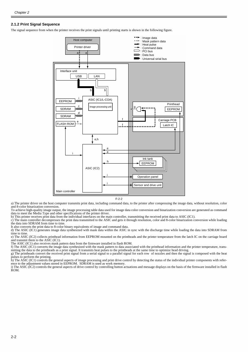
Chapter 2
2-2
2.1.2 Print Signal Sequence0026-6428
The signal sequence from when the printer receives the print signals until printing starts is shown in the following figure.
F-2-2a) The printer driver on the host computer transmits print data, including command data, to the printer after compressing the image data, without resolution, colorand 8-color binarization conversion.To achieve high-quality image output, the image processing table data used for image data color conversion and binarization conversion are generated as commanddata to meet the Media Type and other specifications of the printer driver.b) This printer receives print data from the individual interfaces on the main controller, transmitting the received print data to ASIC (IC1).c) The main controller decompresses the print data transmitted to the ASIC and gets it through resolution, color and 8-color binarization conversion while loadingthe data into SDRAM from time to time.It also converts the print data to 8-color binary equivalents of image and command data.d) The ASIC (IC1) generates image data synthesized with mask data within the ASIC in sync with the discharge time while loading the data into SDRAM fromtime to time.e) The ASIC (IC2) collects printhead information from EEPROM mounted on the printheads and the printer temperature from the latch IC on the carriage boardand transmit them to the ASIC (IC1).The ASIC (IC1) also receives mask pattern data from the firmware installed in flash ROM.f) The ASIC (IC1) converts the image data synthesized with the mask pattern to data associated with the printhead information and the printer temperature, trans-mitting the data to the printheads as a print signal. It transmits heat pulses to the printheads at the same time to optimize head driving.g) The printheads convert the received print signal from a serial signal to a parallel signal for each row of nozzles and then the signal is composed with the heatpulses to perform the printing.h) The ASIC (IC1) controls the general aspects of image processing and print drive control by detecting the status of the individual printer components with refer-ence to the adjustment values stored in EEPROM. SDRAM is used as work memory.i) The ASIC (IC2) controls the general aspects of drive control by controlling button actuations and message displays on the basis of the firmware installed in flashROM.
a a
USB LAN
b b
ASIC (IC1/L-COA)EEPROM
SDRAM EEPROMg
FLASH ROM
ASIC (IC2)
EEPROM
e
e
e,h
e
f
f
h
i
i
i
SDRAM
i
c
d
::
:::::
Image dataMask pattern dataHeat pulseCommand dataPCI busData bus
Host computer
Printer driver
Interface unit
Image processing unit
Operation panel
Latch IC
Printhead
Carriage PCB
Ink tank
Sensor and drive unit
Main controller
Universal sirial bus

Chapter 2
2-3
2.1.3 Print Driving0026-6429
Print and control signals are transferred via the carriage board to the printheads to discharge inks from the nozzle assembly at printing.Each printhead has 12 trains of nozzles arranged in a zigzag pattern.This printer uses two printheads arranged side by side.(In installed state, from left to right, PC, C, PM, GY, MBK, M, Y, BK, GY, PM, C, PC)Print signals directed at each nozzle train are even-numbered nozzle data (Hx-x-DATA-x-EV) and odd-numbered nozzle data (Hx-x-DATA-x-OD). These aretransferred in timing with a data transfer clock (Hx-CLK) and data latch pulses (Hx-LT).The Heat Enable (Hx-x-HE-x) drive control signal enables inks to be discharged from the nozzles.
1. Pint drive controlEach train of nozzles in a printhead has 2,560 nozzles.Ink discharge nozzles are selected split in 40-, 20- or 10-nozzle blocks according to the Block Enable information in the even-numbered nozzle data and odd-num-bered nozzle data.Each selected block of nozzles is impressed with a Heat Enable signal generated with variable pulse widths according to the head rank, head temperature and printertemperature for optimized ink discharges. The nozzles are driven by heater boards in the nozzles to discharge inks. Optimal nozzle blocks are selected accordingto the print path.The diagram below illustrates the relationship between a 40-block nozzle and nozzles driven.
F-2-3
23222120191817161514131211109876543210
2559
01234567891011121314151617181920212223242526272829303132333435363738394041424344454647
39383736353433323130292827262524
4849505152535455565758596061626364656667686970717273
The pattern is repeated until 2560 nozzles is reached.
Prin
thea
dno
zzle
No.
Block No.

Chapter 2
2-4
2. Print drive timingEach printhead houses 12 trains of nozzles, which share the same data transfer clock (Hx-CLK) and data latch pulses (Hx-LT).Even-numbered nozzle data (Hx-x-DATA-x-EV), odd-numbered nozzle data (Hx-x-DATA-x-OD) and the Heat Enable (Hx-x-HE-x) signal are generated for eachnozzle train and controlled individually.Printing is carried out in two ways through reciprocating motion of the carriage.An encoder sensor mounted on the carriage generates a 150-dpi-pitched linear scale detection signal (ENCODER_A) and a signal (ENCODER_B) shifted 120 de-grees in phase. The direction of carriage motion is detected from the status of the ENCODER_B signal relative to the leading edge of the ENCODER_A signal.The printhead is driven using a 2400-dpi timing signal (internal signal), which is generated by dividing the ENCODER_A signal detected at the 150 dpi timing into16 equal sections.Printing in the forward direction is triggered at the leading edge of the detection signal (ENCODER_A).Printing in the backward direction is carried out the same way as printing in the forward direction but at the trailing edge of the detection signal (ENCODER_A),when the order of heated nozzles is reversed depending on the sequence of transfer of even-numbered nozzle data and odd-numbered nozzle data.
F-2-4
150dpi
2400dpi
Internal signal
2400dpi
Low active
Linear scale
Data of block 0
Data of block 0
Data of block 0
Data of block 0
Data of block 2
Data of block 2
Data of block 2
Data of block 2
Data of block 4
Data of block 4
Data of block 4
Data of block 4
Data of block 22
Data of block 22
Data of block 22
Data of block 22
ENCODER_A
ENCODER_B
H0_CLK
H0_A_DATA_0_EV
H0_A_DATA_1_EV
H0_LT
H0_A_HE_1
H0_A_DATA_0_OD
H0_A_DATA_1_OD

Chapter 2
2-5
2.2 Firmware
2.2.1 Operation Sequence at Power-on0012-6310
The sequence of printer operations, from power-on to transition to online mode, is flowcharted below. The printer takes less than 1 minute to initialize itself(*).* Excluding the times spent supplying inks and cleaning the printhead after leaving the printer for extended periods of time.
F-2-5
Power Button ON
Device/resource
initializarion
Printhead/
ink tank check
Media feed system
initialization
Recovery system
initialization
Carriage position
initialization
Remaining ink level detection/
Waste ink level detection
Power-on
automatic recovery operation
Capping
Waiting for print operation
Initialization of softwareInitialization of various devices
Engine status checkEngine startup status checkPrevious power-off status check,etc.
Printhead installation status checkInk tank installation status checkEEPROM check
Cassette pick-up unit initializationRoll feed unit initializationRoll feed unit initializationSensor check
Recovery system return to originSensor check
Carriage motor return to origin

Chapter 2
2-6
2.2.2 Operation Sequence at Power-off0012-6311
Turning off the power switch cuts off the drive voltage supply, launching a firmware power-off sequence as shown below.
If the power cord is disconnected from the wall outlet or the upper cover or any other cover is opend, the printer cancels the ongoing operation and shuts downimmediately. Since printhead capping may or may not have been carried out properly, reconnect the power cord to the wall out and turn on the power switch. Makingsure that the printer has entered online mode, turn off the power switch.
1. Power-off sequence
F-2-6
Power button OFF
If media remains,it is ejected even when printing is in progress.
Media ejection
Power-off automatic recovery
Capping
Sensor system power OFF
Backup of various data
Power-off
Hold down for at least once second
Writing to EEPROM

Chapter 2
2-7
2.2.3 Print Position Adjustment Function0012-6313
This printer supports a print position adjustment for the vertical and horizontal print positions, the bidirectional print position of the printhead mounted on the car-riage, and the feedrate.There are two adjustment modes for the print: automatic adjustment, in which print position adjustment patterns printed are detected by the multi sensor attachedto the lower left part of the carriage, and manual adjustment, in which print position adjustment patterns that are slightly modified from one another are printed, sothat visually verified adjustment values can be set from the operation panel.To make print position adjustments, A3-or-larger-sized roll media or cut media are needed.
2.2.4 Head Management0012-6314
This printer supports a nozzle check function to spot non-discharging nozzles in the printhead.When the printer detects a non-discharging nozzle, it starts cleaning the printhead automatically to correct its discharge failure. If cleaning does not work, the printerbacks up the non-discharging nozzle with an alternative nozzle automatically to ensure unfailing print performance.
Detection timings (automatic):Power-on, carriage cover open detection, print start (check timing variable by selecting Nozzle Check from the system menu).
2.2.5 Printhead Overheating Protection Control0012-6315
When an abnormal temperature rise in the printhead is detected, overheating protection control launches.Overheating could occur in the printhead after a period of print operations without the nozzles being filled with inks.Overheating protection control is implemented on the basis of the temperature detected by the head temperature sensor for each nozzle. When an abnormal temper-ature is detected in any nozzle train, overheating protection control is exerted at one of two levels according to that temperature.
Protection level 1:If the head temperature sensor (DI sensor) detects a temperature higher than the protection temperature, it halts the carriage temporarily at the scan end position inthe direction of travel according to the carriage scan status.Printing resumes when the printhead radiates naturally to cool down below a predetermined temperature or when 30 seconds or longer have elapsed since the de-tection of the higher temperature.
Protection level 2:If the head temperature sensor (DI sensor) detects a temperature higher than the abnormal temperature, the printer shuts down the print operation immediately,moving the carriage to the home position for capping, with an error indication on the display.
2.2.6 Pause between Pages0012-6320
An inter-page function is available to prevent ink rubbing, which keeps paper just printed hanging above the platen and waiting for a predetermined period of timebefore delivery.The wait time is user-programmable from the print driver. This feature is particularly useful on paper that takes time to dry after printing, such as film.
2.2.7 White Raster Skip0012-6322
This printer supports a white raster skip function to bypass carriage scanning in a consecutive sequence of voids in print data, for added throughput.
2.2.8 Sleep Mode0012-6324
The printer has sleep mode to reduce its standby power requirement.The printer transitions to sleep mode automatically when it has been left idle or no print data has been received for a predetermined period of time while the printeris online or offline.The printer exits sleep mode when any operation panel key is activated or print data is received from the host computer.The time to transition to sleep mode is variable from the operation panel (Default: 5minutes).

Chapter 2
2-8
2.2.9 Hard Disk Drive0013-9239
This printer features a hard disk drive, which provides the following functions.- Early release of the host computer- Error recovery- Job preservation- Preserved job print- Job queue handling
1) Early release of the host computerEach print job received from the host computer is preserved to the hard disk drive attached to the printer, so the printer can proceed with independent printing,releasing the host computer before the print job completes.
2) Error recoveryIf a print job aborts as a result of any print problem, such as a paper jam or insufficient paper, the printer reloads the print job stored on the hard disk so it can resumethe print job without having to retransmit the job from the host computer to it.
3) Job preservationPrint jobs are in the common box, a place of temporary data storage, and in the personal box, a place of permanent data storage.Normal print jobs are stored in the common box as they are received. Due to the limited hard disk space available, jobs stored in the common box are deleted fromthe oldest one in sequence.Print jobs can be simply stored in the personal box without printing. Print jobs stored in the common box can be moved to the personal box.
4) Preserved job handlingPrint jobs stored in the personal box or common box can be printed from the operation panel.
5) Job queue handlingMultiple jobs queued for print can be handled. including the raising priority order of selected jobs in the queue or canceling selected print jobs.

Chapter 2
2-9
2.3 Printer Mechanical System
2.3.1 Outline
2.3.1.1 Outline0012-6326
The printer mechanism is broken down into two broad sections: ink passage and paper passage.The ink passage consists primarily of the carriage unit[2] that houses ink tanks[1] and a printhead, purge unit[3] and maintenance cartridge[4], and supplies, whichcirculates, sucks and otherwise handles inks.The paper passage consists of mechanical components, such as the paper feed unit[5], which is designed to feed, convey and deliver paper in two ways.A summary description of each mechanical component of the printer is given below.
F-2-7
[5] [1]
[2]
[3]
[4]
[1]

Chapter 2
2-10
2.3.2 Ink Passage
2.3.2.1 Ink Passage
2.3.2.1.1 Overview of Ink Passage0012-6328
The ink passage comprises ink tanks, a printheads, caps, a maintenance jet tray, a maintenance cartridge, ink tubes interconnecting the mechanical components ofthe printer, and a suction pump that is driven to suck inks. It supplies, circulates, sucks and otherwise handles inks.
The ink passage (per color) is schematically shown below, along with the ink flow.
F-2-8a) Supplying inks from the ink tanks to the ink supply valve assemblyThe ink tanks each contain ink to feed the printhead.Head differences allow the inks to flow from the ink tanks to the subtanks first, then to the ink supply valves.Air is discharged through the air passage of the subtanks to keep the internal pressure of the ink tanks constant.
b) Supplying inks from the ink supply valves to the printheadThe ink stored in an ink tank flows to the printhead when the suction pipe is driven with the ink supply valve opened and the head capped.
c) Supplying inks while printingThe ink supply valves are kept open while printing, so that ink is constantly flowing to the printhead under the negative pressure of the nozzle assembly which iscaused by the discharging inks.Furthermore, waste inks sucked in the cleaning operation and inks from the maintenance jet tray flow into the maintenance cartridge.
Opening all the ink passages (by opening both the ink supply valve and the printhead fixer lever with an ink tank yet to be installed) while an ink tube is being filledwith ink could cause the ink in the ink tube to flow backwards due to a head pressure difference, causing leakage through the hollow needle in the ink tank.As a precaution, never open all the ink passages at the same time while the ink tubes are being filled with inks.
d) Ink agitatingInk will be agitated to prevent the element of the pigment ink from subsiding in the ink tank and the sub-tank. The valve motor drive is transmitted to the agitation cam, the agitation fin in the sub-tank rotates and ink in the sub-tank will be agitated. In addition, ink flowsbackward by moving the piston under the needle(ink supply) up and down in the ink tank, and ink in the ink tank will be agitated.
Maintenance cartridge
Ink tank
Ink supply vavle
Joint
Joint
Carriage unit
Printhead
Cap
Suction pump
Mechanical Drive UnitInk or air flow
Subtank
Agitation fin
Needle(ink supply)
Piston
Needle(air passage)
Valvemotor
Agitationcam

Chapter 2
2-11
2.3.2.2 Ink Tank Unit
2.3.2.2.1 Structure of Ink Tank Unit0012-6329
a) Ink tanksThe ink level in each ink tank is memorized in EEPROM attached to the tank and is detected as a dot count on the basis of the EEPROM information.When an electrode attached to a hollow needle detects no continuity, it displays a message reporting that the ink tank is nearly empty.If the dot count reaches a predesigned value in this state, an ink out condition is assumed.
b) Ink portDepressing the ink tank fixer lever on the printer would cause would cause a hollow needle to pierce the ink tank port sealed by a rubber plug, linking the ink passageof the ink to the printer.
c) Air passageDepressing the ink tank fixer lever on the printer would cause an open hollow needle to pierce the air passage sealed by a rubber plug releasing the internal pressureof the ink tank to keep it constant.
d) Notches for preventing incorrect installationInk tanks are furnished with a notch for preventing incorrect installation.If the installation of an ink tank in incorrect position is attempted, the notch would interfere with it, preventing its installation.The ink tank fixer lever won't lower without the ink tank fully inserted to reach the mounting position, so the ink cannot be supplied.
F-2-9
Ink tank
Ink portAir passage
Notch for preventing incorrect installation
EEPROM
Notch for preventing incorrect installation

Chapter 2
2-12
e) SubtankThe subtank installed under each ink tank complements the work of the ink tank, agitating the ink in the tank.If the ink tank runs out of the ink while printing, the ink stored in the subtank is available, allowing the ink tank to be replaced without having to stop printing.
f) Ink supply valvesInk tank supply valves are located halfway between the ink tanks and the ink tubes. These valves prevent the leakage of inks that might otherwise be caused by theopening of the ink tubes on the side of the ink tanks during their replacement.The ink supply valves are caused to open and close by the valve open/close mechanism that is activated by driving the valve motors.The ink tank unit consists of tank bases each are organized into one group of six colors, and six-color ink tubes.The color-specific ink supply valves will open and close at the same time for all colors.
F-2-10
Subtank
Agitation cam sensor
Hollow needleValve motor
Valve open/closed detection sensor
Ink tube
Ink supply valve
Valve cam

Chapter 2
2-13
2.3.2.3 Carriage Unit
2.3.2.3.1 Functions of Carriage Unit0024-9588
a) Printhead mounting functionThe carriage, which fixes the printhead in position mechanically, is connected to the contacts of the head relay PCB.
b) Control functionThe carriage carries a carriage relay PCB, which relays drive signals from the main controller PCB, a head relay PCB, which relays printhead drive signals to theprinthead, a linear encoder, which generates print timing signals, and a multi sensor, which detects the width of paper and skews in it, adjusts is registration and thehead height.The carriage relay PCB is connected to the main controller PCB by a flexible cable.
c) Carriage drive functionThe carriage is moved over the platen by means of the carriage belt that is driven by the power imparted from the carriage motor.
d) Printhead maintenance functionThis printer performs cleaning operations, such as wiping the printhead and sucking inks, with the carriage halted at its home position.
e) Nozzle check functionThis printer carries out an ink discharge operation with the carriage halted at the head management sensor, locating a non-discharging nozzle in the printhead.
f) Carriage height adjustment functionIf the separation between the face of the printhead and the paper (carriage height) is varied as a result of differing paper thicknesses, crooked or curled paper orother problems, the printer is liable to generate excess mist as the carriage height increases or to result in head rubbing as the carriage height decreases.To maintain an acceptable carriage height, the lift motor is driven according to the selected paper type, feeding method, print conditions (borderless printing/prior-itized picture quality) , environmental condition(temperature/humidity) and multi sensor measurements to automatically adjust the separation between the face ofthe printhead and the paper
The table below shows the relation between the media type and the height of the head.
T-2-1
g) Paper leading edge detection function/paper width detection function/skew detection functionThe multi sensor attached to the lower left part of the carriage detects the leading edge and width of paper feeding on the platen and any skews in it.
h) Automatic printhead position adjustment functionThe multi sensor attached to the lower left part of the carriage reads an adjustment pattern printed on a form and adjusts the print timing of each printhead automat-ically.
i) Remaining roll media detection functionThe printer prints a bar code on roll media upon installation of the roll media. The multi sensor attached to the lower left part of the carriage detects the remainingroll length.
j) Internal unit temperature sensorA thermistor installed on the head relay PCB detects the internal unit temperature near the printhead.
Height of printhead(mm) Media type (reference) Remarks
1.2 Plain paper1.4 Photopaper, Synthetic paper, Film, Plain paper(Line drawing) Capping position1.8 Coated paper(Line drawing)2.0 Plain paper, Coated paper, Fabric banner2.2 Premium matte paper, Fine art(watercolor,block print)2.6 Canvas

Chapter 2
2-14
2.3.2.3.2 Structure of Carriage Unit0028-6252
a) Printhead mountThe printhead is secured to the carriage by the printhead fixer cover and the printhead fixer lever.When the printhead is secured to the carriage, the signal contact of the head relay PCB is pressed against that of the printhead to convey print signals.Furthermore, the ink passage from the ink tanks is connected to the printhead via the ink tubes.
b) Ink portInk is supplied to the printhead via an ink tube, which is connected to ink joints, and runs between the tube guides to reach the carriage and follow its movement.
F-2-11
c) ControllerThe Carriage relay PCB is connected to the head relay PCB by means of a short flexible cable.The flexible cable between the main controller and the carriage relay PCB follows up the motion of the carriage together with the tube guide.A photocoupler encoder mounted in the lower part of the back of the carriage detects a linear scale reading as the carriage moves.
d) Carriage driveMechanical misregistrations in the vertical/horizontal and bidirectional print positions of the printhead mounted can be corrected by selecting Adjust Printer fromthe main menu to shift the print timing.A DC-operated carriage motor drives the carriage reciprocally on the platen by way of the carriage belt.The carriage home position, or the capping position, is detected by the sensor flag on the right side of the carriage and the photointerrupter-based carriage HP sensoron the right side of the printer. When the linear scale position is set as a reference home position for use in subsequent position control operations, the carriage motoris driven by a control signal generated from the main controller PCB.
e) Printhead maintenance unitThis printer cleans the printhead with the carriage halted at its home position.Wiping takes place through the rotation of the motor.Wiper blades mounted on the carriage wipe the printhead while the carriage is halted at its home position.Wet wiping is carried out for added wiping removal performance, whereby the wiper blades are moistened with glycerin as they are pressed against an absorberimpregnated with glycerin.Maintenance jet ejection is carried out on the cap, at the maintenance jet tray, borderless printing ink tray and on the paper surface.A suction operation is carried out by a suction cap in the purge unit.
f) Carriage height adjustment unitThe head height is adjusted with the carriage halted at its home position.The lift motor is driven to rotate the lift shaft within the carriage, in sync with which the lift cams on both sides of the carriage move the head holder up and down,thereby varying the separation between the face of the printhead and the paper.The printhead height is detected from the lift cam sensor within the carriage and the distance of rotation of the lift motor.
g) Multi sensor
[1] Carriage motor[2] Printhead fixer lever[3] Printhead fixer cover[4] Electrical contact[5] Ink tube
[3]
[1]
[2] [4]
[5]

Chapter 2
2-15
The multi sensor attached to the lower left part of the carriage consists of four LEDs and four light-receiving sensors to detect the leading edges and width of paperand skews in it, and to adjust its registration and head height.The multi sensor reference has the white plate attached to it, so that a reference value can be calculated during carriage height measurement by measuring the in-tensity of light reflected upon the white plate.(Service mode: SERVICE MODE>ADJUST>GAP CALIB)
h) Rail cleanerThe shaft cleaner located in the right rear of the carriage helps keep the main rail clean.
i) Internal unit temperature sensorOne thermistor is installed on the head relay PCB on the back of the head holder to detect the internal unit temperature.
F-2-12
[1] Carriage relay PCB [7] Shaft cleaner[2] Multi sensor [8] Maintenance jet tray[3] Head relay PCB [9] Carriage HP sensor[4] Lift cam sensor [10] Multisensor reference[5] Sensor flag [11] Head management sensor unit[6] Lift cam [12] Lift motor
[1]
[2]
[3]
[4] [5]
[6]
[7]
[8]
[9]
[10]
[11]
[12]

Chapter 2
2-16
2.3.2.4 Printhead
2.3.2.4.1 Structure of Printhead0013-8015
Each printhead is an integrated assembly of six trains of nozzles. Capable of controlling each nozzle individually, each printhead implements discharge control forsix colors by itself.
a) Nozzle arrangementThe nozzle assembly is formed of 1,280 nozzles arranged at 600-dpi intervals in a zigzag pattern, offering a total of 2,560 nozzles 1,200-dpi intervals.
F-2-13b) Nozzle assembly structureInks supplied from the ink tanks are filtered through a mesh ink filter before being sent to the nozzle assembly.Each nozzle train is supplied with an ink from the common nozzle chamber.A head drive current subsequently flowing through the nozzle heater boils the ink, generating bubbles to discharge ink drops from the nozzle assembly.
F-2-14
02
13
2559
25572558
2556
02
13
2559
25572558
2556
02
13
2559
25572558
2556
02
13
2559
25572558
2556
02
13
2559
25572558
2556
02
13
2559
25572558
2556
5/600inch
1/1200inch
82/600inch
Resin
Sillicon plate
Heater
Shared ink chamber
Heater

Chapter 2
2-17
2.3.2.5 Purge Unit
2.3.2.5.1 Functions of Purge Unit0012-6344
To maintain high print quality, the purge unit performs maintenance of the nozzles of the printhead.The purge unit supports a capping function, cleaning function, and ink supply function.
a) Capping functionThe capping function presses the cap of the purge unit against the face plate on the nozzle section of the printhead to prevent nozzle drying and dust adhesion.Capping is performed when printing is complete, at the start of the suction operation, and when switching to the standby state due to an error.The capping function also establishes the ink passage between the printhead and purge unit.
b) Cleaning functionThe cleaning function restores the printhead to the state where ink can be easily discharged from nozzles. This function includes the following three types of oper-ations.
- Wiping operationThis operation is performed to remove paper fibers and dried ink from the face plate.
- Pumping operationThis operation is performed to remove ink from the nozzles and fill the nozzles with fresh ink.
- Maintenance jet operationThis operation is performed to spray ink from the nozzles to the cap, the borderless ink jet tray, and on paper to remove bubbles in the nozzles and dust and otherforeign particles.
c) Ink supply functionThe suction pump of the purge unit operates together with the ink supply valve to supply ink to the printhead during the initial filling and ink level adjustment.
Details of the cleaning function are shown in the table below.
Cleaning modeName of Service mode or
PRINT INF(Name of Main Menu)
Operation Description of cleaning
Cleaning 1 CLN-A-1/CLN-M-1(Head Cleaning A)
Normal cleaning Removes dried ink from nozzles, thick ink accumulated on the face, and paper particles.
Cleaning 2 CLN-A-2 Ink level adjustment and cleaning Adjust the ink level in the head by suction, and then performs normal cleaning.
Cleaning 3 CLN-A-3 Initial filling ink Fills the empty tube (during initial installation) with ink, and then performs normal cleaning.
Cleaning 4 CLN-M-4(Replace P.head)
Ink drainage for head replacement Drains ink to replace the head (drains only the ink in the head).
Cleaning 5 CLN-M-5(Move Printer)
Ink drainage for secondary transport Drains ink from the head and tube for secondary transport.
Cleaning 6 CLN-A-6/CLN-M-6(Head Cleaning B)
Normal (strong) cleaning Performs suction stronger than when adjusting the ink filling amount in the head or normal cleaning to unclog nozzles.
Cleaning 7 CLN-A-7 Aging Performs idle ejection after replacement of the head.Cleaning 10 CLN-A-10
(Move Printer)Ink filling after secondary transport Fills the empty tube (during installation after secondary
transport) with ink, and performs normal cleaning.Cleaning 11 CLN-A-11 Ink filling after head replacement Performs normal cleaning after head replacement and ink
filling.Cleaning 15 CLN-A-15 Dot count suction Performs suction to remove ink adhered to dried nozzles and
thick ink accumulated on the face when the dot count reaches the prescribed value.
Cleaning 16 CLN-A-16 Precipitated ink agitation Performs the agitation (ink supply valve open/close) operation to prevent the ink ingredient from precipitating.
Cleaning 17 CLN-A-17 Cleaning (weak) Performs cleaning weaker than normal cleaning to unclog nozzles.

Chapter 2
2-18
Cleaning operation timings are as follows.
Printer status Cleaning operation Consumption (typ.)*1
Standby 168 hours elapsed capped Cleaning 1 (Normal Cleaning)
1g
At least 720 to 960 hours elapsed since the last session of Cleaning 2, 3, 6 or 10 (480 hours after initial installation)
Cleaning 6 (Normal (strong) Cleaning)
5g
At initial installation and 96 hours elapsed since the last session of Cleaning 16 Cleaning 16 (Precipitated ink agitation)
-
1 hour elapsed capped with a specified number of dots discharged per chip completed after last wiping
Wiping + Idle ejection 0.013g
Power-on At initial installation Cleaning 3 (initial filling ink)
40g
Both heads and inks available
The print operation has completed. 168 to 720 hours elapsed capped Cleaning 1 (Normal Cleaning)
1g
At least 720 to 960 hours elapsed since the last session of Cleaning 2, 3, 6 or 10 (360 to 480 hours after initial installation)
Cleaning 6 (Normal (strong) Cleaning)
5g
At least 960 to 2160 hours elapsed since the last session of Cleaning 2, 3, 6 or 10 (480 hours after initial installation)
Cleaning 2 (Ink level adjustment and cleaning)
10g
At least 96 hours elapsed since the last session of Cleaning 16
Cleaning 16 (Precipitated ink agitation)
-
At least 1 hour elapsed capped with a specified number of dots discharged per chip completed after last wiping
Wiping + Idle ejection 0.013g
Print operation aborted (uncapped) and CR error occurring
Up to 72 hours elapsed after an abort
Cleaning 1 (Normal Cleaning)
1g
Over 72 hours elapsed after an abort Cleaning 6 (Normal (strong) Cleaning)
5g
Print operation aborted (uncapped) and no CR error occurring Cleaning 11 (ink filling after head replacement)
10g
No heads are available Cleaning 10 (ink filling on secondary transport)
40g
Power off Specified number of dots discharged per chip completed since the last session of wiping Wiping + Idle ejection 0.013gBefore the start of printing
Less than 168 hours elapsed capped Idle ejection 0.013gAt least 168 hours elapsed capped Cleaning 1 (Normal
Cleaning)1g
Before printing in the wake of an error occurrence Cleaning 1 (Normal Cleaning)
1g
Printing Before scanning while printing Idle ejection (+Wiping) - (0.013g)After the end of printing
A specified number of dots (color) discharged per chip since the last session of Cleaning 2, 3, 6 or 1 Cleaning 6 (Normal (strong) Cleaning)
5g
A specified number of dots discharged per chip after the last session of wiping Wiping + Idle ejection 0.013g3 minutes elapsed since the last session of capping Wiping + Idle ejection 0.013gTotal 2 hours elapsed uncapped since the last session of Cleaning 1, 2, 3, 6 or 10 Cleaning 1 (Normal
Cleaning)1g
When the Head Cleaning menu choice is executed
Manual Cleaning (Head Cleaning A) Cleaning 1 (Normal Cleaning)
1g
Manual cleaning (Head cleaning B) Cleaning 6 (Normal (strong) Cleaning)
5g
When the Replace Print Head menu choice is executed
After head replacement Cleaning 2 (ink level adjustment and cleaning) + Cleaning 4 (ink drainage for head replacement)
10g
When the Move Printer menu choice is executed
After the Move Printer menu choice is executed Cleaning 5 (ink drainage for secondary transport)
10g
After power-on at secondary installation After power-on at secondary installation
15g
*1: Quantities of ink consumption by nozzle train

Chapter 2
2-19
2.3.2.5.2 Structure of Purge Unit0012-6341
a) CapsThe caps cap the nozzle assembly in the left printhead during capping and cleaning. The part of the caps that comes into contact with the face plate of the nozzleassembly is made of rubber. Two caps are in position to meet each of the printheads mounted on the carriage (six trains of nozzles).The caps are activated to protect the nozzle assembly on capping. When the carriage moves to the home position , the caps are elevated by the cap cam that is drivenby the capping motor, capping the nozzle assembly to protect it.These caps cap the nozzle assembly to suck inks from the printhead by means of the suction pump.
F-2-15b) WipersThe wipers are driven by the purge motor to wipe the six trains of nozzles in the nozzle assembly in the printhead simultaneously.A pair of wiper blades are in position to ensure wiping performance. The wiping operation operates on a slide wiping basis, sliding the wiper blades via wiper camsthrough the normal rotation of the purge motor.Wiping is executed by the wiper blades moving at a constant speed to the front of the printer after the end of a print or suction operation.A wiper blade set perpendicularly to the head wipes the entire face of the printhead, followed by a narrower blade wiping the nozzle assembly.The wiper blades are cleaned before they are replaced at the wiping position after wiping to preserve wiping performance.Wiper blade cleaning is carried out by scraping off the inks that have been wiped off from the head with an ink scraper linked to the maintenance cartridge, thenwiping the blades with a blade cleaner.Wet wiping is carried out for added wiping removal performance, whereby the wiper blades are moistened with glycerin as they are pressed against an absorberimpregnated with glycerin. The quantity of glycerin used is managed by counting the number of times the wiper blades have been pressed against the absorber.When this count falls to equal any of the following values, either a replacement warning (continued print available) or replacement required indication (service callerror) is issued.
F-2-16c) PumpThe pump (suction pump) is a tube pump that pressurizes the ink tubes with rotating rollers to generate a negative pressure for sucking inks.A single tube is sequentially pressurized by a pair of rotating rollers to control the level of ink suction by a wide margin.
Display TimesReplacement warning indication 71,250 timesService calls 75,000 times
Wiper unit
Carriage lockpin
Cap
Purge motor
Glycerin tank
Pump encoder sensor
Pump cam sensor
Cap
Ink scraperGlycerinabsorber
Printhead
Wiper blades
Blade holder
Glycerin tank
Wiper cam

Chapter 2
2-20
The timing at which the rotating rollers rotate is detected by the pump cam sensor, with the distance of rotation being controlled by the driving of the purge motor.
F-2-17
Cap
Purge motorPump encoder sensor
Pump cam sensor
Cap
Ink tubes
Suction pump
Rotating rollers
Suction pump
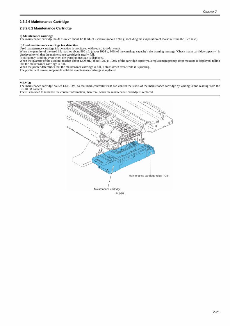
Chapter 2
2-21
2.3.2.6 Maintenance Cartridge
2.3.2.6.1 Maintenance Cartridge0012-6346
a) Maintenance cartridgeThe maintenance cartridge holds as much about 1200 mL of used inks (about 1280 g: including the evaporation of moisture from the used inks).
b) Used maintenance cartridge ink detectionUsed maintenance cartridge ink detection is monitored with regard to a dot count.When the quantity of the used ink reaches about 960 mL (about 1024 g, 80% of the cartridge capacity), the warning message "Check maint cartridge capacity" isdisplayed to tell that the maintenance cartridge is nearly full.Printing may continue even when the warning message is displayed.When the quantity of the used ink reaches about 1200 mL (about 1280 g, 100% of the cartridge capacity), a replacement prompt error message is displayed, tellingthat the maintenance cartridge is full.When the printer determines that the maintenance cartridge is full, it shuts down even while it is printing.The printer will remain inoperable until the maintenance cartridge is replaced.
MEMO:The maintenance cartridge houses EEPROM, so that main controller PCB can control the status of the maintenance cartridge by writing to and reading from theEEPROM content.There is no need to initialize the counter information, therefore, when the maintenance cartridge is replaced.
F-2-18Maintenance cartridge
Maintenance cartridge relay PCB

Chapter 2
2-22
2.3.2.7 Air Flow
2.3.2.7.1 Air Flow0014-8865
This printer has two fans, a mist fan used to collect mist and a suction fan used to suck media onto the platen.Ink mists floating during printing or springing back from the paper are collected in the mist fan unit by air flow in the printer.Two mist fans located on the rear side of the printer makes the airflow that carries the ink mists to the mist fan unit.
F-2-19A duct is located under the platen, along with a platen ink box unit used for collecting waste ink during borderless printing and idle discharges. The suction fancollects the ink mist in the duct into the suction fan duct unit.
F-2-20
Mist fan
Suction fan
Suction fan duct unit
Duct

Chapter 2
2-23
2.3.3 Paper Path
2.3.3.1 Outline
2.3.3.1.1 Overview of Paper Path0013-8780
The key components of the paper passage consist of a feed roller assembly, a pinch roller drive that locks and releases the pinch roller and sensors that detect thefeed status of paper. It feeds paper in trays, conveys and delivers paper.
Basic operation of the roll media loading sequence1) Multi sensor light quantity adjustment.2) Paper leading edge detection sensor.3) Paper left edge detection sensor.4) Barcode read. * Performed only if Chk Remain.Roll is turned on.5) Paper skew detection sensor.6) Paper right edge detection sensor.7) Trim edge first detection sensor. * Performed only if Trim Edge First is turned on.8) Leading edge cutting. * Leading edge cutting is executed under the following conditions.
a. Trim Edge First is set to Forced.b. Trim Edge First is set to Automatic, and the need for cutting determined.c. A barcode is detected when Chk Remain.Roll is on (forced cutting, regardless of the setting of Trim Edge First).
9) Paper leading edge detection sensor.
Basic operation of the cut sheet loading sequence1) Paper trailing edge detection sensor.2) Multi sensor light quantity adjustment.3) Paper width detection sensor.4) Paper leading edge detection sensor.5) Paper skew detection sensor.
MEMO:Press the [ ] key while the printer is offline to deliver paper, the [ key to rewind the paper.

Chapter 2
2-24
2.3.3.2 Paper Path
2.3.3.2.1 Structure of Feed Roller Unit0024-9813
a) Paper feed assemblyThe paper feed assembly consists of paper feeding mechanisms, such as a feed roller that is driven by the feed motor and a pinch roller unit that follows up themotion of the feed roller.Paper feeds horizontally under the printheads on the carriage as it is kept level on the platen to prevent cockle.
b) SensorsThe paper feed assembly includes sensors for detecting the status of paper feeding and that of the mechanical components that make up the paper passage.For more details, see TECHNICAL REFERENCE > Detection Functions with Sensors.
c) Roll media pick-up drive unitWhen the roll media feeds, the roll media pick-up pressure clutch 1 turns on to actuate the torque limiter in the pick-up drive unit. Thus the back tension works toprevent the roll media from sags or skew.At this time, if the paper tube of roll media is inside diameter of 3 inches, the pick-up pressure solenoid and roll media pick-up pressure clutch 2 turn on to increasethe back tension (about 2.6 times higher than before).
F-2-21
Feed motor
Roll media pick-uppressure clutch 1
Roll media pick-uppressure clutch 2
Pick-up pressure solenoid
Feed rollerHP sensor
Feed rollerencoder sensor
Roll media
Release lever
Roll holder
Media sensorPinch roller
Feed roller
Printhead

Chapter 2
2-25
2.3.3.3 Cutter Unit
2.3.3.3.1 Structure of Cutter Unit0012-6386
If the print driver is configured to use a cutter with roll media, cutter unit attached to the left side of the carriage cuts roll media automatically. Cutter unit won't cutroll media if the print driver is configured otherwise.
F-2-22
Cutter unit

Chapter 2
2-26
2.4 Printer Electrical System
2.4.1 Outline
2.4.1.1 Overview0024-9589
The printer electrical system consists of the main controller PCB and power supply PCB which are mounted on the back side of the printer, the carriage relay PCB,the head relay PCB, and printhead which are mounted in the carriage, the operation panel on the right upper cover and other electrical components such as sensors,and motors.The main controller PCB manages the image data processing and the entire electrical system, and controls relay PCBs and driver functions.
F-2-23
Power supply PCB Main controller PCB
Head relay PCB Carriage relay PCB
Media take-up relay PCB
HDD
Media take-up PCB
Operation panel PCB

Chapter 2
2-27
F-2-24
Host computer
BAT801Lithium battery
Interfacecontrol function
Remaining ink leveldetection function
LED control function
Solenoid/Clutch control function
Sensor detection function
IC1501/IC1701IC1601-IC1603
Power supply control function
+26V generation function
+21.5V generation function
Power supply PCB
Head relay PCB
Carriagerelay PCB
Multi sensor
DI sensor readingcontrol function
Temperature readingcontrol function
Thermistor
Motor control function
AC inlet
IC1
IC1201HDD controllerHDD
Driver
IC803RTC
IC802EEPROM
Solenoids/ Clutches
IC601-IC604SDRAM
IC701/IC703 FLASH ROM
IC2802/IC2900IC2902/IC3100
Motor driver
IC1 EEPROM
EEPROM Multi sensorcontrol function
EEPROM
IC301/IC304
EEPROM control function
Linear encodersensor Linear encoder detection function
Hard disk drive control function
Heat pulse control function
Operation panel control function
PWM control function
Operation panel
Image data control function
IC104Motor driver
Sensors
Fans
Ink tank ROM PCB
Maintenance cartridgerelay PCB
Motors
Head
Main controller PCB
SO-DIMM
Network Board
Media take-up PCB
Media take-up relay PCB

Chapter 2
2-28
2.4.2 Main Controller
2.4.2.1 Main controller PCB components0029-0084
F-2-25a) ASIC (IC1/IC2)The ASIC(IC1/IC2) with a 32/16-bit internal bus is driven in sync with the 330/66 MHz external clock. It supports the following functions:
Image processing unitThis unit converts the RGB multi-value image data or CMYK multi-value data received from the host computer through the interface connector to the binary imagedata for the ink colors used.
DMA controllerThis controller control DMA transfer of the data transferred through the input interfaces such as the USB and expansion card slot as well as DMA transfer of thedata stored in the DIMM.
Image data generation/output functionThis function generates image data for color printing from the received image data and the mask pattern (corresponding to print mode) stored in the FLASH ROM,and stored the generated image data in DIMM. It also outputs the generated image data to the carriage relay PCB.
Interrupt controllerThis controller receives and processes internal interrupts and external interrupts from the USB, image processing unit, and expansion card slot.
Timer functionEven when the printer is turned off, the timer function is held on using the RTC(IC803) and lithium battery(BAT801) to assist the cleaning function.When the power cord is plugged to the outlet, power is supplied to the RTC and therefore the lithium battery power is not consumed.
Heat Enable signal control functionThis function uses the pulse width to perform variable control of the time of application of the Heat Enable signal to the nozzle heater board for each printheadnozzle array.
Linear scale count functionThis function reads the linear scale when the carriage moves, thus generating the ink discharge timing. It also counts the linear scale timing cycle using the referenceclock to measure the carriage moving speed.
Dot count functionThis function controls the discharge dots used as the information for Heat Enable signal control, maintenance jet control, cleaning control, and remaining ink levelfor each nozzle array.
Operation panel control functionThis function controls serial communication with the operation panel.
PWM control functionThis function controls driving of the suction fan and mist fan as well as the temperature of the printhead.
Remaining ink level detection functionThis function detects the remaining level of each color of ink based on the signal received from the hollow needle mounted in the ink tank unit.
LED control functionThis function controls the LEDs on the ink tank unit.
I/O port functionThis function controls input signals from sensors.
Power ON/OFF control functionThis function controls turning on/off of the drive power (32V and 5.1V) supplied from the power supply PCB.
Head DI sensor read control functionThis function controls read operation by the head DI sensor.
Multi sensor control functionThis function controls the LED, adjusts the gain, and controls obtainment of the reading for the multi sensor.
IC2902
IC803
IC2802IC2802
IC802
IC2900IC2900
IC703
IC1201
IC701
IC601
IC1
IC2
IC3100
BAT801
IC602
IC603
IC604
IC2700
J401

Chapter 2
2-29
EEPROM control functionThis function controls the EEPROMs of individual ink tanks, the maintenance cartridge EEPROM, the EEPROM on the maintenance cartridge relay PCB, and thehead EEPROM in addition to the on-board EEPROM.
Motor control functionThis function controls the carriage motor, feed motor, valve motor, purge motor and lift motor based on the input signals from sensors.
b) Driver IC (IC3100)This IC generates a carriage motor control signal based on the control signal from the ASIC.
c) Driver IC (IC2802)This IC generates feed motor control signal based on the control signal from the ASIC.
d) Driver IC (IC2900)This IC generates purge motor and valve motor control signals based on the control signal from the ASIC.
e) Driver IC (IC2902)This IC generates lift motor control signal based on the control signal from the ASIC.
f) Driver IC (IC2700)This IC generates solenoid and clutch control signals based on the control signal from the ASIC.
g) DIMMs (IC601/IC602/IC603/IC604)The DIMM comprising a 128-MB SDR-SDRAM is connected to the 32-bit data bus to be used as a work area.During print data reception, it is also used as an image buffer.It cannot be expanded.
h) FLASH ROM (IC701/IC703)A 128-MB flash ROM is connected to the 8-bit data bus to store the printer control program.
i) EEPROM (IC802)The 128-KB EEPROM stores various setting values, adjustment values, log data, counter values related to the user/servicing.
j) SO-DIMMThe 256-MB SO-DIMM (J401) is connected to the 32-bit data bus to be used as a work area.During print data reception, it is also used as an image buffer.It cannot be expanded.
k) HDD controller (IC1201)This controller control the hard disk drive.
MEMO:After replacement of the main controller PCB, the printer must be started up in the service mode to copy over the setting and adjustment values to the new PCBproperly (the service mode will be switched to the PCB replacement mode automatically).

Chapter 2
2-30
2.4.3 Carriage Relay PCB
2.4.3.1 Carriage relay PCB components0012-6406
F-2-26a) Image data relay functionThis function relays the image data from the main controller PCB to the printhead.The function for processing image data is not supported.
b) Sensor relay functionThis function relays the input signals from the multi sensor, lift cam sensor, carriage cover sensor, and linear encoder to the main controller PCB.
2.4.4 Head Relay PCB
2.4.4.1 Head relay PCB components0017-8321
F-2-27a) Latch IC (IC301,IC304)DI sensor read control functionObtains reading value of the DI sensor in the printhead and the head rank value for each color and outputs them to the main controller based on the control commandsfrom the main controller.
Environment temperature read control functionOutputs the environment temperature detected by the thermistor on the head relay PCB to the main controller based on the control commands from the main con-troller.
Relay function of the power to the logic components in the printheadSupplies the power to the logic components in the printhead based on the control commands from the main controller.
b) Multi sensor control ICThese IC's generates the LED control signals and makes gain adjustment for the multi sensor.
c) Image data relay functionThis function relays the image data from the main controller PCB to the printhead.
d) Sensor relay functionThis function relays the input signals from the multi sensor, lift cam sensor, carriage cover sensor, and linear encoder to the main controller PCB.
IC301IC304

Chapter 2
2-31
2.4.5 Motor Driver
2.4.5.1 Media take-up PCB components0014-2480
F-2-28a) Driver IC (IC104)
Media take-up motor drive functionThis function controls the Media take-up motor based on the control signals from the main controller.
Sensor relay functionThis function relays the input signals from the Media take-up paper detection sensor and Media take-up on/off sensor to the main controller PCB.
2.4.6 Maintenance Cartridge Relay PCB
2.4.6.1 Maintenance cartridge relay PCB components0013-6532
F-2-29a) EEPROM (IC1)The 2-KB EEPROM stores all information written in the EEPROM on the main controller PCB.
2.4.7 Power Supply
2.4.7.1 Power supply block diagram0012-6414
F-2-30The power supply converts AC voltages ranging from 100V to 240V from the AC inlet to DC voltages for driving the ICs, motor, and others.The voltage generator circuits include the +32V generation circuit for driving motors, fans, and the +5.1V generator circuit for driving sensors, logic circuits.When in the power saving mode, the power supply cut out the +32V and the +5.1V.Power ON/OFF operation is controlled by the main controller PCB. When the upper cover is open, the power supply cut out only the +32V power to the carriage.
IC104
IC 1
Operation panel
Transformer
DC power supply
control circuit
+5.1V
generation circuit
+32V
generation circuitPOWER ON
Rectifying circuit
Noize filter circuit
AC inlet100V to 240V
Power supplyMain controller PCB
+5V/+3.3V
generation circuit
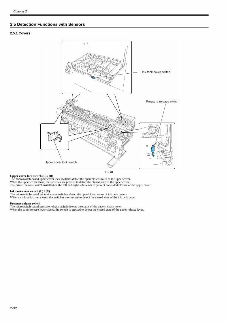
Chapter 2
2-32
2.5 Detection Functions with Sensors
2.5.1 Covers0012-6490
F-2-31Upper cover lock switch (L) / (R)The microswitch-based upper cover lock switches detect the open/closed states of the upper cover.When the upper cover close, the switches are pressed to detect the closed state of the upper cover.The printer has one switch installed on the left and right sides each to prevent one-sided closure of the upper cover.
Ink tank cover switch (L) / (R)The microswitch-based ink tank cover switches detect the open/closed states of ink tank covers.When an ink tank cover closes, the switches are pressed to detect the closed state of the ink tank cover.
Pressure release switchThe microswitch-based pressure release switch detects the status of the paper release lever.When the paper release lever closes, the switch is pressed to detect the closed state of the paper release lever.
Upper cover lock switch
Ink tank cover switch
Pressure release switch

Chapter 2
2-33
2.5.2 Ink passage system0024-9591
F-2-32Pump cam sensorAs the cam rotates, it shields the sensor light of the photointerrupter-based pump cam sensor or allows it to be transmitted. The status of the purge unit, such ascapped, suction and wiping, is detected by the combination of the pump cam sensor detection and the control of pump motor rotation by the pump encoder sensor.
F-2-33
Pump encoder
Pump cam sensor
Head management sensor
Valve open/closeddetection sensor
Agitation cam sensor
- Carriage lock - Capping- Suction
- Air passage valve open- Idle suction
- Printing- Suction during printing
- Wiping - Carriage lock- Air passage
- Carriage move - Maintenance jet- Idle suction
Rotary flag Sensor

Chapter 2
2-34
Pump encoder sensorThe photointerrupter-based sensor reads slits in the encoder film of the Purge motor and controls the amount of its rotaion accordingly.
F-2-34Valve open/closed detection sensorThe photointerrupter-based valve open/closed detection sensor detects the status of the valve.The sensor detects that the ink supply valve is open when the sensor light is shielded by a flag linked with the valve cam.
Agitation cam sensorThe photointerrupter-based agitation cam sensor detects the status of the agitation cam.The sensor detects the agitation cam home position when the sensor light allows it to be transmitted.
Ink detection sensorThe ink detection sensor detects the presence or absence of the ink in an ink tank with respect to the status of continuity between two hollow needles.When the ink level in the tank falls to a point below the wall surrounding the hollow needles in the air passage, continuity with the hollow needle on the ink supplyside is disrupted, causing the sensor to detect that the ink is out.
F-2-35Head management sensorThe photo-transmission-type sensor detects that the printhead is discharging ink.The carriage moves to and stops at the detection positions for individual nozzle arrays. When the carriage is at a stop, nozzles discharge ink on after another.The sensor detects each nozzle due to the voltage change caused when ink discharged from the nozzle blocks the sensor light.
Non-discharging nozzle detection is carried out at the following timings:- After the execution of Cleaning 1, Cleaning 2, Cleaning 3, Cleaning 6 or Cleaning 10- After the number of copies that has been set by the user menu choice Nozzle Check Frequency have been printed
If more than a specified number of non-discharging nozzles have been located in one session of non-discharging nozzle detection, the normal cleaning sequence islaunched before a second session of non-discharging nozzle detection is conducted. If more than a specified number of non-discharging nozzles are located in thesecond session of non-discharging nozzle detection, the normal (High) cleaning session is launched before a third session of non-discharging nozzle detection isconducted.If there are at least 320 non-discharging nozzles out of 2560 nozzles as the result of non-discharging nozzle detection, printing is canceled after displaying a messageto replace the head.However, if service mode: [SERVICE MODE] > [SETTING] > [HEAD DOT INF] is [ON], the following message appears.If there are at least 30 nozzles unable to correct the non-discharging state and the number of non-discharging nozzles is less than 100 out of 2,560 nozzles as theresult of non-discharging nozzle detection, printing can continue after displaying a message to check the printing. Also, if the number of non-discharging nozzlesis at least 100 but less than 320 nozzles, printing can continue after displaying a message to check the head. And if there are at least 320 non-discharging nozzles,printing is canceled after displaying a message to replace the head.
F-2-36
Sensor
Slits
Ink tank
Wall
Rubber plug
Needle(air passage)Needle (ink supply)
Printhead
Nozzle unit
Head management
sensor unit

Chapter 2
2-35
2.5.3 Carriage system0028-6197
F-2-37Carriage cover sensorThe photointerrupter-based carriage cover sensor detects the opening and closing of the carriage cover.When the carriage cover is closed, the sensor light is shielded by the sensor arm, enabling the sensor to detect that the carriage cover is closed.
Carriage HP sensorThe photointerrupter-based carriage HP sensor detects the home position of the carriage.Installed on the right side plate of the printer, the sensor detects an edge of the carriage home position on the carriage unit under carriage movement control.The printer establishes the carriage home position from the position at which its edge is detected as a reference position.
Linear encoder sensorMounted on the back of the carriage, the linear encoder detects the position of the carriage from a slit in the linear scale during its movement.
Lift cam sensorThis sensor is a photointerrupter-based sensor. After the sensor light is shielded by the flag, the lift motor is driven by a predetermined number of pulses to regulatethe separation between the printheads and platen automatically.
Ambient temperature sensorThe thermostat-based ambient temperature sensor mounted on the head relay PCB detects the ambient temperature to which the carriage is exposed.The resistance of the thermistor that varies as a function of temperature changes in the printer is transmitted to the main controller via the carriage relay PCB.The ambient temperature is used to help calibrate the head temperature sensor and detect abnormal ambient temperatures.
Head temperature sensorThe head temperature sensor detects the temperature of the printhead.The printhead temperature is transmitted to the main controller via the carriage relay PCB.The printhead temperature is used to help control the head drive and detect abnormal printhead temperatures.
Printhead contact detectionThe printhead contact detects the status of printhead installation by electrical means.The contact detects the status of contact from voltage changes in the flexible cables on the carriage side that come into contact with two terminals of the printheadwith remote contact surfaces, the power terminals and GND terminal.
Multi sensor
Lift cam sensor
Carriage HP sensor
Carriage cover sensor
Linear encoder sensor
Head relay PCB
Linear scale
Carriage relay PCB

Chapter 2
2-36
Multi sensorThe photo-reflection-type multi sensor is composed of four LEDs and four light-sensitive sensors. It detects the leading edge, skewing, and width of media and isused for adjustment of the registration, head height, and color calibration.During head adjustment, the light reflected by the GAP LED is detected by two light-sensitive sensors (GAP-Far, GAP-Near) )to calculate the head height from thedifference between the measurements.When color calibration is executed, the light reflected from the printed color chart by the the three-colors LED (red, blue, green) is detected by the light-sensitivesensor (COLOR-SNS), so the color correction is implemented on the basis of the readings.During media detection, the light reflected by the diffuse reflection LED and regular reflection LED and the three-colors LED (red, blue, green) are detected by thelight-sensitive sensors (EDGE-SNS, COLOR-SNS).Ink mist adhering to the sensor could deliver incorrect measurement readings when color calibration is executed. If the ink dot count exceeds a tolerance, the serviceerror (E194-4034) would occur. If it does, execute service mode: SERVICE MODE > ADJUST > GAP CALIB. after the multisensor has been replaced to clearthe dot count.
F-2-38
- Service mode: After SERVICE MODE > ADJUST > GAP CALIB. has been carried out, pass paper to make sure that it is detected properly.- If performing the calibration in parallel with the "Head Posi Adj." of the main menu, perform the "Head Posi Adj." first for the sake of higher color calibrationaccuracy.
GAP LED
Media detection
Head height detectionColor and media detection
Platen
Media
Light-sensitive sensor(COLOR-SNS)
Light-sensitive sensor(EDGE-SNS)
Light-sensitive sensor(GAP-Far) Light-sensitive sensor
(GAP-Near)
Diffuse reflection LED
Regular reflection LED
Three-colors LED(red/green/blue)
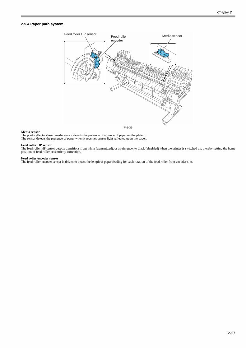
Chapter 2
2-37
2.5.4 Paper path system0014-8916
F-2-39Media sensorThe photoreflector-based media sensor detects the presence or absence of paper on the platen.The sensor detects the presence of paper when it receives sensor light reflected upon the paper.
Feed roller HP sensorThe feed roller HP sensor detects transitions from white (transmitted), or a reference, to black (shielded) when the printer is switched on, thereby setting the homeposition of feed roller eccentricity correction.
Feed roller encoder sensorThe feed roller encoder sensor is driven to detect the length of paper feeding for each rotation of the feed roller from encoder slits.
Media sensorFeed roller HP sensorFeed rollerencoder

Chapter 2
2-38
2.5.5 Media take-up Unit0013-8115
F-2-40Media take-up on/off sensorThe photointerrupter-based media take-up on/off sensor detects the switch status of the media take-up unit.When the media take-up switch is set to ON, the sensor arm transmits the sensor light, power-on the media take-up unit.When the media take-up switch is set to OFF, the sensor arm shields the sensor light, shutting down the media take-up unit.
Media take-up paper detection sensorWhen the sensor light is shielded by a loop of printed paper, the media take-up motor rotates to take up the paper.
2.5.6 Others0013-8116
F-2-41Temperature/humidity sensorThis sensor detects the temperature and humidity around the printer so that the measured values are used for head height adjustment, idle discharge control, wasteink evaporation amount calculation, and suction fan control.
ON
OFF
Media take-up on/off sensor
Media take-up paper detection sensor
Temperature/humidity sensor

Chapter 3 INSTALLATION


Contents
Contents
3.1 Transporting the Printer .................................................................................................................................................3-13.1.1 Transporting the Printer ............................................................................................................................................................... 3-1
3.1.1.1 Transporting the Printer ..................................................................................................................................................................................3-13.1.2 Reinstalling the Printer .............................................................................................................................................................. 3-14
3.1.2.1 Reinstalling the Printer..................................................................................................................................................................................3-14

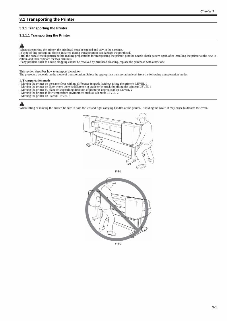
Chapter 3
3-1
3.1 Transporting the Printer
3.1.1 Transporting the Printer
3.1.1.1 Transporting the Printer0026-6829
When transporting the printer, the printhead must be capped and stay in the carriage. In spite of this precaution, shocks incurred during transportation can damage the printhead. Print the nozzle check pattern before making preparations for transporting the printer, pint the nozzle check pattern again after installing the printer at the new lo-cation, and then compare the two printouts. If any problem such as nozzle clogging cannot be resolved by printhead cleaning, replace the printhead with a new one.
This section describes how to transport the printer.The procedure depends on the mode of transportation. Select the appropriate transportation level from the following transportation modes.
1. Transportation mode- Moving the printer on the same floor with no difference in grade (without tilting the printer): LEVEL 0- Moving the printer on floor where there is difference in grade or by truck (by tilting the printer): LEVEL 1- Moving the printer by plane or ship (tilting direction of printer is unpredictable): LEVEL 2- Moving the printer in low temperature environment such as sub zero: LEVEL 2- Moving the printer on its end: LEVEL 3
When lifting or moving the printer, be sure to hold the left and right carrying handles of the printer. If holding the cover, it may cause to deform the cover.
F-3-1
F-3-2

Chapter 3
3-2
The printer main unit weights approximately 110 kg. When moving the printer, have at least six people hold it from both sides taking care not to hurt their back.
F-3-3Do not place or transport the printer with load placed only at the center of the printer. Otherwise the printer can be deformed or damaged.
F-3-4

Chapter 3
3-3
When tilting the printer, be sure to hold the carrying handles or the bottom's metal cover of the printer and place a cardboard or blanket on the floor to preventdamage to the printer.
F-3-5When tilting the printer, support the printer at bottom left and right side of the printer.If the printer is supported at any other location, the printer may be damaged or deformed.
F-3-6
Bottom
Top
Top
Bottom

Chapter 3
3-4
a. LEVEL 0Moving the printer on the same floor without difference in grade
Transportation procedure1) Turn off the power and check that the heads are capped.2) Open the upper cover and mount the belt stopper.
F-3-7
When mounting the belt stopper, be careful not to move the carriage by applying too much pressure. If the carriage moves when the heads are capped, the rubberpart of the cap may touch the nozzles on the heads and damage the print head.
3) Close the upper cover.4) Remove the paper and roll holder.5) Remove power cord and interface cable.6) Unlock the casters on the stand and move the printer slowly.
If the printer is subjected to strong vibrations when it is moved, it can cause ink leakage or damage to the print head. Be sure to move the printer slowly and carefully.
Item Description[Prep. MovePrinter] on the Main menu This need not be performed.Allowed tilting angle Do not tilt.Ink consumption No ink is consumed.Ink tank It may be installed or removed.Separation of main unit and stand They do not need to be separated.Maintenance cartridge Install.
There is no need to open a new maintenance cartridge.Replacement of consumable parts There is no need to replace consumable parts.Service support No service support is necessary.

Chapter 3
3-5
b. LEVEL 1Moving the printer on a floor with difference in grade or by truck
Transportation procedure1) If there is a message instructing to replace the maintenance cartridge or check the remaining ink, replace the maintenance cartridge.2) Remove the paper and roll holder.3) From [Set/Adj. Menu] > [Prep. MovePrinter], select [LEVEL 1].4) Press the [OK] key and perform [LEVEL 1] MOVE PRINTER.5) If the consumable parts counter is checked and a message to replace consumable parts appear, check the consumable parts counter from service mode and replacethe necessary consumable part.See "d. Replacing consumable parts during transportation."Repeat [LEVEL 1] after replacing consumable parts and resetting the counter.6) When MOVE PRINTER completed message appears, turn off the power, and remove the power cord and interface cable.7) Open the upper cover and raise the ejection guide.
F-3-8
Item Description[Prep. MovePrinter] on the Main menu Perform [LEVEL 1].Allowed tilting angle Lengthwise: -30 to +30 degrees
Rotation: -10 to +10 degrees
Ink consumption No ink is consumed.Ink tank It may be installed or removed.Separation of main unit and stand They do not need to be separated.Maintenance cartridge Install.
There is no need to open a new maintenance cartridge.However, if there is a message instructing to replace the maintenance cartridge or check the remaining ink, replace with new maintenance cartridge before transporting.
Replacement of consumable parts Replacement of consumable parts and resetting of counter may be necessary.Service support If consumable parts must be replaced, service support is necessary.

Chapter 3
3-6
8) Remove the ejection support and lower the ejection guide.
F-3-99) Install the belt stopper.
F-3-10
When mounting the belt stopper, be careful not to move the carriage by applying too much pressure. If the carriage moves when the heads are capped, the rubberpart of the cap may touch the nozzles on the heads and damage the print head.
10) Close the upper cover.11) Attach the cushioning materials and tape.12) Unlock the casters on the stand and move the printer slowly.
If the printer is subjected to strong vibrations when it is moved, it can cause ink leakage or damage to the print head. Be sure to move the printer slowly and carefully.

Chapter 3
3-7
c-1. LEVEL 2Transporting by plane or shipTransporting in low temperature environment such as sub zero
Item Description[Prep. MovePrinter] on the Main menu Perform [LEVEL 2].Allowed tilting angle Lengthwise: -30 to +30 degrees
Rotation: -30 to +30 degrees
Ink consumption Approximately 1200ml of ink is consumed.Ink tank Remove all ink tanks.Separation of main unit and stand Separate.Maintenance cartridge Replace with new maintenance cartridge before performing transporting procedure.
Two new maintenance cartridges must be provided.(One for disposing waste ink and one to be installed new maintenance cartridge during transportation)
Replacement of consumable parts Replacement of consumable parts and resetting of counter may be necessary.Service support If consumable parts must be replaced, service support is necessary.

Chapter 3
3-8
c-2. LEVEL 3Moving the printer on its end
Transportation procedure1) If there is a message instructing to replace the maintenance cartridge or check the remaining ink, replace the maintenance cartridge.2) Remove the paper and roll holder.3) From [Set/Adj. Menu] > [Prep. MovePrinter], select [LEVEL 2] or [LEVEL 3].4) Press the [OK] key and perform [LEVEL 2] or [LEVEL 3] MOVE PRINTER.5) If the counter is checked and a message to replace consumable parts appear, check the consumable parts counter from service mode and replace the necessaryconsumable part. See "d. Replacing consumable parts during transportation." Repeat [LEVEL 2] or [LEVEL 3] after replacing consumable parts and resetting the counter.6) Follow the displayed message and open the left and right ink tank covers.
F-3-11
Item Description[Prep. MovePrinter] on the Main menu Perform [LEVEL 3].Allowed tilting angle Lengthwise: -90 to +90 degrees
Rotation: -30 to +30 degrees
Ink consumption Approximately 1200ml of ink is consumed.Ink tank Remove all ink tanks.Separation of main unit and stand Separate.Maintenance cartridge Replace with new maintenance cartridge before performing transporting procedure.
Three new maintenance cartridges must be provided.(Two for disposing waste ink and one to be installed new maintenance cartridge during transportation)
Replacement of consumable parts Replacement of consumable parts and resetting of counter may be necessary.Service support If consumable parts must be replaced, service support is necessary.

Chapter 3
3-9
7) Raise the ink tank lock lever and remove all ink tanks.
F-3-12
Put the removed ink tanks in the plastic bag with the ink supply part [1] upward and close the opening.
F-3-13
8) Return the ink tank lock lever and close the ink tank cover.Ink drainage is performed automatically. Replace the maintenance cartridge when the cartridge replacement message appears.
When transporting the printer, install the new maintenance cartridge to avoid the ink leakage.
9) When MOVE PRINTER completed message appears, turn off the power, and remove the power cord and interface cable.10) Open the upper cover and raise the ejection guide.
F-3-14
F
F
PM
R
G
BK
M
B
[1]

Chapter 3
3-10
11) Remove the ejection support and lower the ejection guide.
F-3-1512) Install the belt stopper.
F-3-16
When mounting the belt stopper, be careful not to move the carriage by applying too much pressure. If the carriage moves when the heads are capped, the rubberpart of the cap may touch the nozzles on the heads and damage the print head.
13) Close the upper cover.14) Attach the cushioning materials and tape.15) If a basket is installed, remove the basket.16) Remove the printer from the stand.Hold the transporting handles at left and right bottom of the printer with three persons on each side and separate the printer from the stand.17) Reverse the assembly procedure to disassemble the stand and media take-up unit as necessary and pack them.18) Pack the printer and transport.
If the printer is subjected to strong vibrations when it is moved, it can cause ink leakage or damage to the print head. Be sure to move the printer slowly and carefully.

Chapter 3
3-11
d. Replacing consumable parts during transportationDuring [MOVE PRINTER], if a message to replace consumable parts appear, check the consumable parts counter from service mode and replace the necessaryconsumable parts that is over the threshold value of counter in the following table.See "Service mode" about how to check the counter.The consumable parts to be replaced and counter to be reset depends on the [LEVEL].
F-3-17
When replacing consumable parts, check for leaking waste ink. When replacing each consumable part, be careful of leaking waste ink especially from the markedarea [A] and avoid tilting the part when removing.
F-3-18
No Part number Name Q'tyService Mode Threshold value of
counter (Unit: ml) Level x (Main menu)PARTS xx
[1] QL2-2110 WASTE INK ABSORBER UNIT 1 Wia-1 581 1, 2, 3[2] QL2-2108 WASTE INK ABSORBER UNIT (L) 2 Wia-3/Wia-4 143[3] QL2-1650 WASTE INK ABSORBER UNIT (S) 1 Wia-5 47[4] QM3-3069 SUCTION FAN UNIT 1 Wia-6 152[5] QL2-1663 DUCT 1[6] QM3-7025 FAN UNIT 2 Mi-1 241 2, 3[7] QM3-1033 INK SUPPLY MOUNT UNIT (L) 1 If there is waste ink, perform waste ink disposal or parts
replacement. And confirm that the ink leakage has not caused to the surrounding area of ink supply mount unit.
[8] QM3-1034 INK SUPPLY MOUNT UNIT (R) 1
[1] WASTE INK ABSORBER UNIT
[2][1]
[7]
[5]
[6]
[6][4]
[8]
[2]
[3]
[A]

Chapter 3
3-12
F-3-19
F-3-20
F-3-21
[2] WASTE INK ABSORBER UNIT (L)[3] WASTE INK ABSORBER UNIT (S)
[4] SUCTION FAN UNIT
[5] DUCT
[A]
[A]
[A]
[A]
[A]

Chapter 3
3-13
F-3-22
[6] FAN UNIT
[A]

Chapter 3
3-14
3.1.2 Reinstalling the Printer
3.1.2.1 Reinstalling the Printer0020-5722
1. Installing after transporting by LEVEL 0 or LEVEL 1.If ink drainage was not performed when transporting by LEVEL 0 or 1, remove the belt stopper and attach the power cord and interface cable after moving theprinter to the installation location, and then check the operation of the printer (with test pattern).
2. Installing after transporting by LEVEL 2 or LEVEL 3.If ink drainage was performed when transporting by LEVEL 2 or LEVEL 3, follow the installation procedure which is nearly identical to the procedure when in-stalling for the first time.

Chapter 3
3-15


Chapter 4 DISASSEMBLY/REASSEMBLY


Contents
Contents
4.1 Service Parts...................................................................................................................................................................4-14.1.1 Service Parts................................................................................................................................................................................. 4-1
4.2 Disassembly/Reassembly...............................................................................................................................................4-24.2.1 Disassembly/Reassembly............................................................................................................................................................. 4-2
4.3 Points to Note on Disassembly and Reassembly ...........................................................................................................4-54.3.1 Note: Items that should never be disassembled ........................................................................................................................... 4-54.3.2 Moving the carriage manually ..................................................................................................................................................... 4-54.3.3 Units requiring draining of ink .................................................................................................................................................... 4-54.3.4 External Covers............................................................................................................................................................................ 4-64.3.5 Drive Unit .................................................................................................................................................................................. 4-144.3.6 Carriage Unit.............................................................................................................................................................................. 4-154.3.7 Ink Tube Unit ............................................................................................................................................................................. 4-204.3.8 Feeder Unit................................................................................................................................................................................. 4-224.3.9 Purge Unit .................................................................................................................................................................................. 4-234.3.10 Ink Tank Unit ........................................................................................................................................................................... 4-244.3.11 Linear Encoder......................................................................................................................................................................... 4-274.3.12 Head Management Sensor ....................................................................................................................................................... 4-284.3.13 PCBs ........................................................................................................................................................................................ 4-294.3.14 Opening the Cap/Moving the Wiper Unit................................................................................................................................ 4-304.3.15 Opening and closing ink supply valves ................................................................................................................................... 4-314.3.16 Draining the ink ....................................................................................................................................................................... 4-32
4.4 Applying the Grease.....................................................................................................................................................4-334.4.1 Applying the Grease .................................................................................................................................................................. 4-33
4.5 Adjustment and Setup Items ........................................................................................................................................4-364.5.1 Adjustment Item List ................................................................................................................................................................. 4-364.5.2 Procedure after Replacing the Carriage Unit or Multi Sensor ................................................................................................... 4-364.5.3 Procedure after Replacing the Feed Roller or Feed Roller Encoder.......................................................................................... 4-364.5.4 Procedure after Replacing the Head Management Sensor......................................................................................................... 4-36

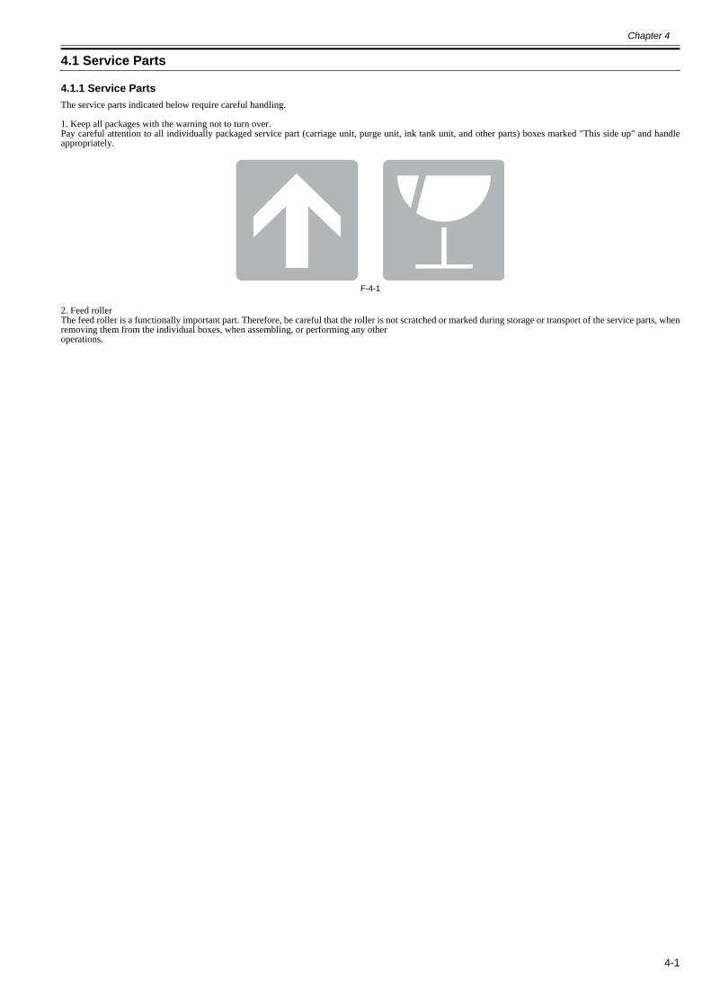
Chapter 4
4-1
4.1 Service Parts
4.1.1 Service Parts0012-6508
The service parts indicated below require careful handling.
1. Keep all packages with the warning not to turn over.Pay careful attention to all individually packaged service part (carriage unit, purge unit, ink tank unit, and other parts) boxes marked "This side up" and handleappropriately.
F-4-1
2. Feed rollerThe feed roller is a functionally important part. Therefore, be careful that the roller is not scratched or marked during storage or transport of the service parts, whenremoving them from the individual boxes, when assembling, or performing any otheroperations.

Chapter 4
4-2
4.2 Disassembly/Reassembly
4.2.1 Disassembly/Reassembly0014-8946
See the Parts Catalog for the disassembly and reassembly procedures. The following four main units do not apply.Main Units:1. Carriage unit2. Ink tube unit3. Purge unit4. Ink tank unitThe parts layout illustration in the Parts Catalog shows the figure numbers associated with the disassembly procedure for each product.
Main unit disassembly and assembly flows* Ink drainage in the dotted lines may be performed using either the automatic or manual ink drain procedure.
F-4-2
<Legend > c: Connector h: Hook s: Screw
Printer
Automatic ink drain
Manual ink drain
Left/right circle cover (L) (h1)
Left/right circle cover (S) (h1)
Left/right side covers (s3, h2)
Left/right tank cover units(s3)
Upper rear cover (s5)
Upper cover
Open left/right ink tank units(s4)
Upper left/upper right covers(h1)
Rear cover right (s4)
Rear cover left (s2)
Left/right printheads
Left/right joint bases
Ink tube joint
Ink tube cover (s2)
Flexible cable (c3)
Carriage PCB cover (s4)
Carriage unit
Move the carriage toabove the platen
Head management sensor(s1)
Lift unit (s5)
Cutter unit
Pulley base (s3)
1. Carriage Unit Disassembly Flow

Chapter 4
4-3
F-4-3
F-4-4
<Legend > c: Connector h: Hook s: Screw
Flexible cable (c5)
Ink tube unit
2. Ink Tube Unit Disassembly Flow
Printer
Automatic ink drain
Manual ink drain
Left/right circle covers (L) (h1)
Left/right circle covers (S) (h1)
Left/right side covers (s3, h2)
Left/right tank cover unit (s3)
Upper rear cover (s5)
Upper cover
Open left/right ink tank units(s4)
Upper left/upper right covers(h1)
Rear cover right (s4)
Rear cover left (s2)
Left/right printhead
Left/right joint bases
Ink tube joint
Ink tube cover (s2)
Flexible cable (c3)
Carriage PCB cover (s4)
Carriage unit
Move the carriage toabove the platen
Head management sensor(s1)
Cable fixer base (s3)
Lift unit (s5)
Cutter unit
Pulley base (s3)
<Legend > c: Connector h: Hook s: Screw
Printer
Right circle cover (L) (h1)
Right circle cover (S) (h1)
Right side covers (s3, h2)
Operation panel (h1, c2)
Right front cover (s2)
Upper right cover (h1)
Purge unit (c1, s3)
Move the carriage toabove the platen
3. Purge Unit Disassembly Flow

Chapter 4
4-4
F-4-5
<Legend > c: Connector h: Hook s: Screw
Printer
Automatic ink drain
Manual ink drain
Right circle cover (L) (h1)
Right circle cover (S) (h1)
Right side covers (s3, h2)
Left/right tank cover units(s3)
Drain the ink in subtanks
Move the carriage toabove the platen
Ink tank unit(c5, s2)
4. Ink Tank unit Disassembly Flow
Remove the left/rightink tube joints
Left/right tank cover units(s3)

Chapter 4
4-5
4.3 Points to Note on Disassembly and Reassembly
4.3.1 Note: Items that should never be disassembled0012-6514
Assemblies that should never be removed after initial factory adjustments, are indicated by the presence of red screws.Under no circumstance should these red screws be loosened or removed. Removing these screws will render the printer out of alignment forever.
F-4-6
4.3.2 Moving the carriage manually0014-8950
When moving the carriage, hold it by the handle [1] shown below.
Move the carriage as required during assembly and disassembly to prevent the carriage from contacting the parts to be removed. You cannot move the carriage when capping has been performed. Refer to DISASSEMBLY/REASSEMBLY > Points to Notes on Disassembly and Reassembly> Opening the caps and moving the wiper unit to remove the caps, and then move the carriage.
F-4-7
4.3.3 Units requiring draining of ink0014-8953
When disassembling the following units, drain the ink completely, to prevent ink leakage. For ink drain instructions, refer to DISASSEMBLY/REASSEMBLY >Points to Notes on Disassembly and Reassembly > Draining the ink.
[1] Carriage unitRefer to DISASSEMBLY/REASSEMBLY > Points to Notes on Disassembly and Reassembly > Carriage unit.[2] Ink tube unitRefer to DISASSEMBLY/REASSEMBLY > Points to Notes on Disassembly and Reassembly > Ink tube unit.[3] Ink tank unitRefer to DISASSEMBLY/REASSEMBLY > Points to Notes on Disassembly and Reassembly >Ink tank unit.
[1]

Chapter 4
4-6
4.3.4 External Covers0014-8958
a) Left circle cover (L)/Right circle cover (L)Removing the left circle cover (L)/right circle cover (L)1) To remove circle cover (L) [1], insert flathead screwdriver [2] at the position shown in the figure to remove claw [3] and turn the cover forward to remove.
F-4-8Installing the left circle cover (L)/right circle cover (L)1) Install circle cover (L) [1] with its part [2] inserted in arrow mark [3] of the right side cover and turn the cover backward to install.
F-4-9b) Left circle cover (S)/Right circle cover (S)Removing the left circle cover (S)/right circle cover (S)1) Remove circle cover (S) [1] by turning it forward to remove the hook.
F-4-10
[2][1]
[3]
[2]
[1][3]
[1]

Chapter 4
4-7
Installing the left circle cover (S)/right circle cover (S)1) Install circle cover (S) [1] with its part [2] inserted in part [3] of the side cover and turn the cover rearward to install.
F-4-11c) Left side cover/Right side coverRemoving the left side cover/right side cover1) To remove left and right side covers [1], remove left and right circle covers (L) and left and right circle covers (S).2) Remove three screws [2] and two hooks [3], and remove the side cover by opening its bottom side.
F-4-12
[2][3]
[1]
[1]
[3]
[2]
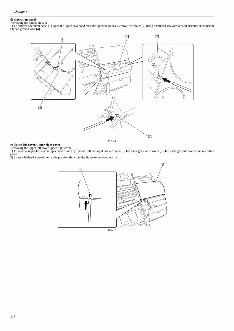
Chapter 4
4-8
d) Operation panelRemoving the operation panel1) To remove operation panel [1], open the upper cover and raise the ejection guides. Remove two claws [2] using a flathead screwdriver and disconnect connector[3] and ground wire [4].
F-4-13e) Upper left cover/Upper right cover Removing the upper left cover/upper right cover1) To remove upper left cover/upper right cover [1], remove left and right circle covers (L), left and right circle covers (S), left and right side covers and operationpanel.2) Insert a flathead screwdriver at the position shown in the figure to remove hook [2].
F-4-14
[3]
[4][1]
[2]
[2]
[1][2]
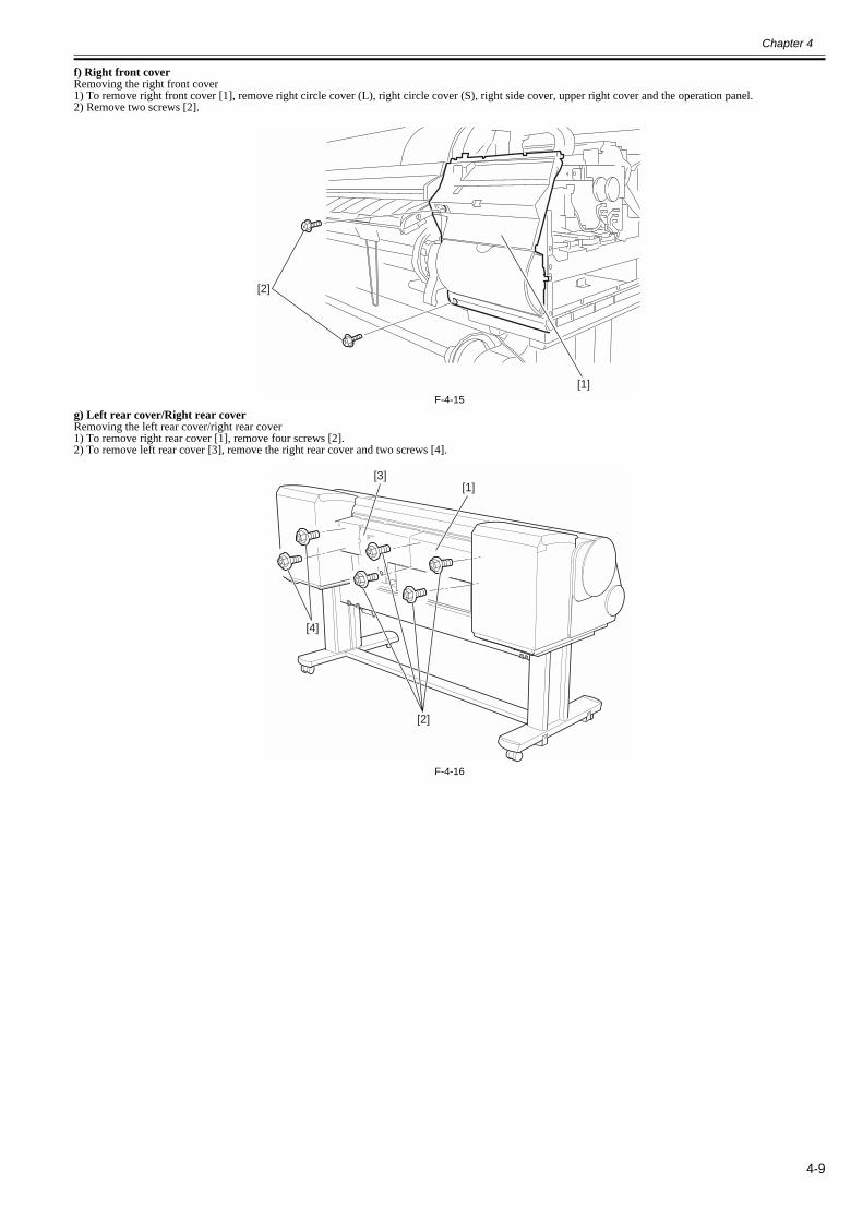
Chapter 4
4-9
f) Right front coverRemoving the right front cover1) To remove right front cover [1], remove right circle cover (L), right circle cover (S), right side cover, upper right cover and the operation panel.2) Remove two screws [2].
F-4-15g) Left rear cover/Right rear coverRemoving the left rear cover/right rear cover1) To remove right rear cover [1], remove four screws [2].2) To remove left rear cover [3], remove the right rear cover and two screws [4].
F-4-16
[1]
[2]
[1][3]
[2]
[4]
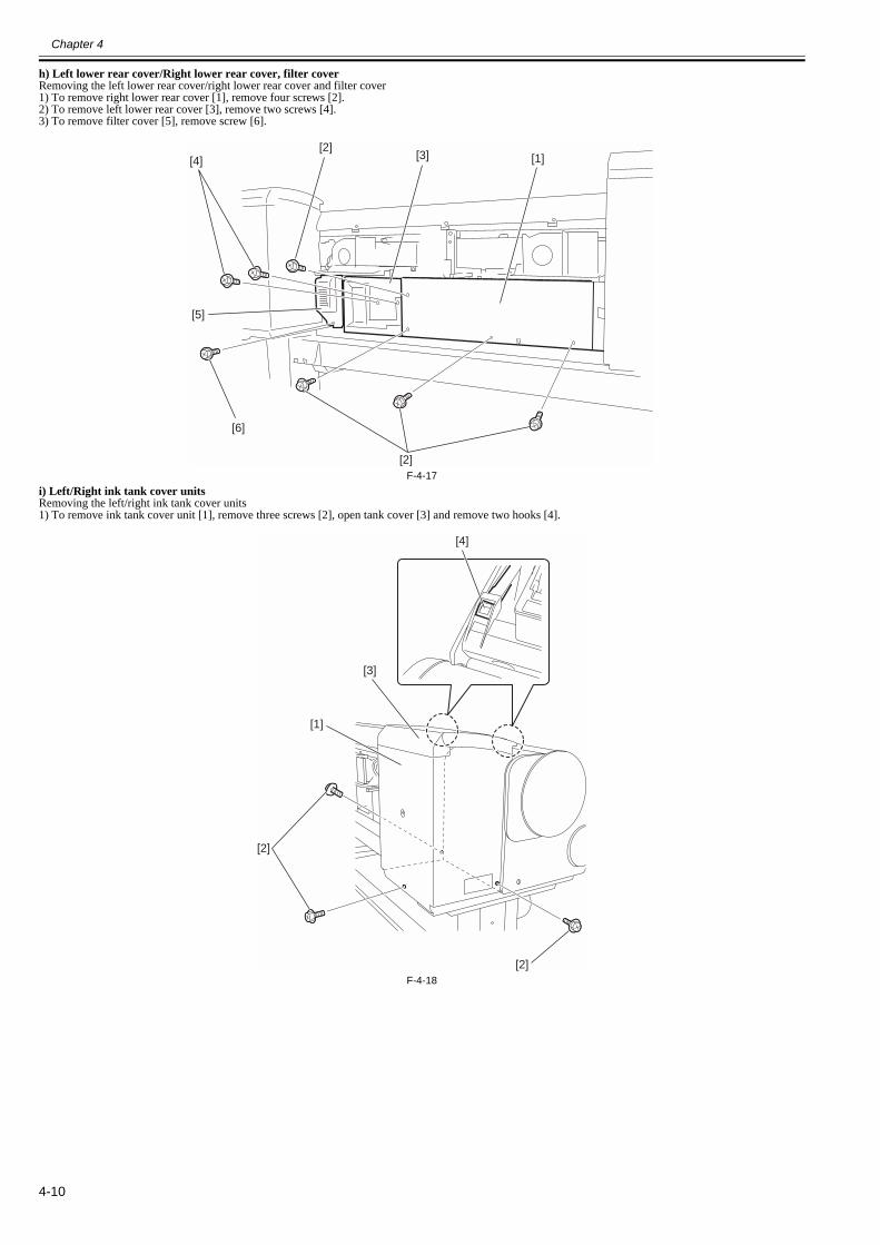
Chapter 4
4-10
h) Left lower rear cover/Right lower rear cover, filter coverRemoving the left lower rear cover/right lower rear cover and filter cover1) To remove right lower rear cover [1], remove four screws [2].2) To remove left lower rear cover [3], remove two screws [4].3) To remove filter cover [5], remove screw [6].
F-4-17i) Left/Right ink tank cover unitsRemoving the left/right ink tank cover units1) To remove ink tank cover unit [1], remove three screws [2], open tank cover [3] and remove two hooks [4].
F-4-18
[1][3]
[2]
[4]
[6]
[2]
[5]
[2]
[2]
[4]
[1]
[3]

Chapter 4
4-11
j) Left/Right ink tank unitsOpening the left/right ink tank units1) To open the left/right ink tank units, remove left/right circle covers (L), left/right circle covers (S), left/right side covers, upper left/right covers and left/right inktank cover units.2) Remove two screws [1].3) Remove screw [2] from the support plate at inner side of the printer.4) Remove screw [4] from the support plate [3] at outer side of the printer, loosen screw [5] and slide the support plate to open the ink tank unit.(The following figure is the case of the left ink tank unit.)
F-4-19
The ink tank units will lock themselves when they are opened to the maximum allowable angle.Be sure to open the ink tank unit to their maximum allowable angle to prevent them from turning over.
k) Upper rear coverRemoving the upper rear cover1) To remove the upper rear cover, remove left/right circle covers (L), left/right circle covers (S), left/right side covers, upper left/right covers, left/right rear coversand left/right ink tank cover units and then open the left/right ink tanks.2) Remove two screws [1] on front side of the printer and three screws [2] on the rear side, and then remove upper rear cover [3].
F-4-20
[1]
[2]
[5]
[3]
[4]
[1]
[1]
[2]
[3]

Chapter 4
4-12
Note on installing the upper rear cover1) Fit three rear-panel screws [1] into screw holes on the right side.
F-4-21l) Upper coverRemoving the upper cover1) To remove the upper cover, remove left/right circle covers (L), left/right circle covers (S), left/right side covers, upper left/right covers, left/right rear covers,right cover unit and upper rear cover.2) Remove upper cover [2] while opening left/right arm stays [1] outward one by one.
F-4-22
[1]
[2]
[1]
[1]
[2] [2]

Chapter 4
4-13
m) Release leverRemoving the release lever1) To remove release lever [1], remove the purge unit and then remove the release lever. To do so, keep pinch roller [2] pressurized to ease the work of phasealignment during gear installation.
Reinstalling the release lever1) To install the release lever, align the gear of the release lever with mark [3] (phase) in the receiving gear.
F-4-23
[1]
[2]
[3]

Chapter 4
4-14
4.3.5 Drive Unit0014-8962
a) Feed motor Removing the feed motor 1) To remove feed motor [1], loosen four screws [2] and remove timing belt [3] and spring [4].2) Remove four loosened screws [2] to release feed motor [1] and remove the connector.
Reinstalling the feed motorTo reassemble the feed roller drive timing belt [3] into position, set the tension of timing belt [3] by adjusting the pressure of spring [4]. Then, fix feed motor [1].
F-4-24b) Action to take after replacing the feed roller encoder and feed roller This printer as shipped has the feed roller eccentricity (that is, variations in the rate of paper feed from rotation to rotation) corrected for enhanced media feed ac-curacy. When the feed roller HP sensor or feed roller encoder and feed roller pertaining to the correction of eccentricity variations has been replaced, therefore,they should require adjustment.Execute service mode under the following conditions to launch automatic adjustment:Service mode: SERVICE MODE > ADJUST > PRINT PATTERN > LF TUNINGMedia type: Glossy photo paper
If adjustment cannot be done properly by selecting "SERVICE MODE > ADJUST > PRINT PATTERN > LF TUNING" (auto adjustment), carry out manual ad-justment.
Service mode SERVICE MODE > ADJUST > PRINT PATTERN > LF TUNING2Media type: Gloss photo paperCheck the printed pattern and enter values for adjustment.
[3]
[4]
[1]
[2]
[2]

Chapter 4
4-15
4.3.6 Carriage Unit0025-0362
a) Removing the carriage unit1) Drain the ink. See Disassembly/Reassembly > Points to Note on Disassembly/Reassembly > Draining the ink.2) Turn off the power and move the carriage to above the platen. If the carriage is locked at its home position, insert a Phillips screwdriver from the right side intohole [1] in the shaft of the lifting unit in the purge unit and turn it counterclockwise. This will lower cap [2] and lock pin [3], allowing the carriage to be moved.
F-4-253) Remove the printheads.4) Release the ink tube from the guide, detach four link levers [1] from the printhead fixer lever, than remove two joint bases [2].
F-4-26
[1]
[3][2]
[2]
[1]
[2]

Chapter 4
4-16
Cover the joints in the ink tube, as with a PVC bag, to keep inks from splashing from them.
F-4-27
5) Remove two screws [1] and ink tube cover [2].
F-4-286) Remove four screws [1] and open carriage relay PCB cover [2].
F-4-297) Disconnect five flexible cables from the carriage relay PCB.
[1]
[2]
[1]
[2]
[1]

Chapter 4
4-17
Never peel off tape [1] that fixes the ink tube when detaching the joints of the ink tube on the upper part of the carriage or when removing the joint base from thecarriage.
F-4-30
8) Twist off belt fixer knob [1] to loosen the belt, and remove spring [2], guide [3] and pulley [4].
F-4-319) Release carriage belt from the pulley of the carriage motor.
[1]
[2]
[4]
[3]
[1]
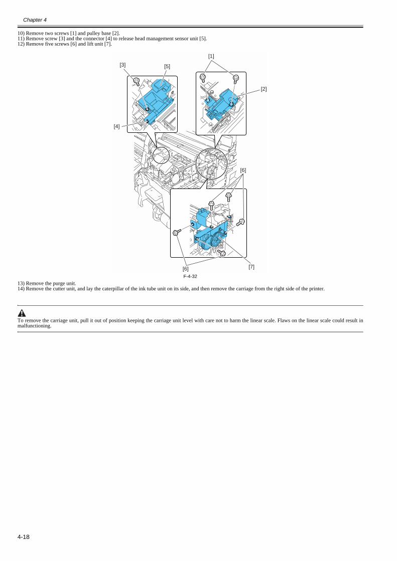
Chapter 4
4-18
10) Remove two screws [1] and pulley base [2].11) Remove screw [3] and the connector [4] to release head management sensor unit [5].12) Remove five screws [6] and lift unit [7].
F-4-3213) Remove the purge unit.14) Remove the cutter unit, and lay the caterpillar of the ink tube unit on its side, and then remove the carriage from the right side of the printer.
To remove the carriage unit, pull it out of position keeping the carriage unit level with care not to harm the linear scale. Flaws on the linear scale could result inmalfunctioning.
[1]
[3] [5]
[2]
[4]
[6]
[6] [7]

Chapter 4
4-19
b) Mounting the carriage beltTo install the carriage belt, put in the point of the belt to the interior of the groove [1], and have all the cogs of carriage belt [3] engaged with belt stopper [2].
F-4-33c) Note on replacing the carriage unit and the multi sensorWhen either carriage unit or multi sensor has been replaced, be sure to replace the multi sensor reference plate(QL2-8099: MOUNT, SENSOR ADJUSTING) aswell.
d) Action to take after replacing the carriage unit and the multi sensorBecause the distance between the multi sensor (in the carriage unit) and the nozzles (in each printhead) is varied from one unit to another, the printer has its opticalaxis corrected and paper gap adjustment sensor gain and sensor calibration adjusted prior to shipment. When the carriage unit or multi sensor has been replaced,they should require adjustment.
Execute service mode under the following conditions to launch automatic adjustment:
1) Optical axis correction - Service mode: SERVICE MODE > ADJUST > PRINT PATTERN > OPTICAL AXISMedia type: Gloss photo paper
2) Paper gap adjustment- Service mode: SERVICE MODE > ADJUST > GAP CALIB.
e) Action following the replacement of the carriage unit, carriage motor, carriage belt or linear encoder sensorAfter the carriage unit or carriage motor or carriage belt or linear encoder sensor have been removed or replaced, execute the following service mode.- Service mode: SERVICE MODE > ADJUST > CR MOTOR COG
f) Precautions against handling the carriage shaft
The carriage shaft is functionally important part. Therefore, be sure to note the following points.- Do not touch the shaft.- Do not allow the shaft to get scratched or marked.- Do not apply the grease to the shaft.
[2]
[3]
[3]
[2]
[1]

Chapter 4
4-20
4.3.7 Ink Tube Unit0014-8966
a) Removing ink tube unit1) Drain the ink. See Disassembly/Reassembly > Points to Note on Disassembly/Reassembly >Draining the ink.2) Remove the carriage unit. See Disassembly/Reassembly > Points to Note on Disassembly/Reassembly > Carriage Unit.3) Disconnect five flexible cables from the main controller PCB.4) Remove the flexible cable leading to the carriage PCB cover from the guide.5) Remove three screws [1] and release ink tube fixer base [2] from the frame.
F-4-346) Remove joint [1] of the ink tube unit from left and right ink tank unit to remove ink tube unit [2].
F-4-35
Never peel off tape [1] that fixes the ink tube when detaching the joints of the ink tube on the upper part of the carriage or when removing the joint base from thecarriage.When replacing the ink tube unit, be sure that the tapes [1] are posted to the new ink tube unit.
F-4-36
[1]
[2]
[1][2]
[1]

Chapter 4
4-21
b) Reassembling ink tube units When the ink tube unit has been replaced, turn on the power without mounting the printhead and the ink tanks.Then, mount the printhead and ink tanks as directed by message guidance.
After detaching the joint of the ink tube unit, the joint might become easy to come off by the ink that has adhered to it.In that case, please wash the joint by alcohol and remove the adhering ink.
F-4-37

Chapter 4
4-22
4.3.8 Feeder Unit0014-8972
a) Handling the feed roller
The feed roller is a functionally important part. Therefore, be sure to note the following points when handling the roller.- Do not hold the roller with one hand or warp its shape.- Do not touch the roller surface (coated surface).- Do not allow the roller to get scratched or marked.- Hold the roller at two points; location D and one of the locations A, B, or C as shown in the figure below.
F-4-38
b) Action to take after replacing the feed roller encoder and feed roller This printer as shipped has the feed roller eccentricity (that is, variations in the rate of paper feed from rotation to rotation) corrected for enhanced media feed ac-curacy. When the feed roller HP sensor or feed roller encoder and feed roller pertaining to the correction of eccentricity variations has been replaced, therefore,they should require adjustment.Execute service mode under the following conditions to launch automatic adjustment:Service mode: SERVICE MODE > ADJUST > PRINT PATTERN > LF TUNINGMedia type: Glossy photo paper
If adjustment cannot be done properly by selecting "SERVICE MODE > ADJUST > PRINT PATTERN > LF TUNING" (auto adjustment), carry out manual ad-justment.
Service mode SERVICE MODE > ADJUST > PRINT PATTERN > LF TUNING2Media type: Gloss photo paperCheck the printed pattern and enter values for adjustment.
A
D
B
C

Chapter 4
4-23
4.3.9 Purge Unit0014-8978
a) Removing the purge unit1) Turn off the power and move the carriage to above the platen. If the carriage is locked at its home position, insert a Phillips screwdriver from the right side intohole [1] in the shaft of the lift unit in the purge unit and turn it counterclockwise. This will lower cap [2] and lock pin [3], allowing the carriage to be moved.
F-4-392) Remove connector [1] and three screws [2] and then remove purge unit [3].
F-4-40
[1]
[3][2]
[1]
[2]
[3]

Chapter 4
4-24
4.3.10 Ink Tank Unit0014-8979
a) Removing ink tank units1) Drain the ink. See Disassembly/Reassembly > Points to Note on Disassembly/Reassembly > Draining the ink.2) Detach the joint [1] between the ink tube unit and ink tank unit.3) Remove four screws [2] and five connectors [3] and then remove the ink tank unit.
F-4-41
After detaching the joint between the ink tube unit and the ink tube of the ink tank unit, the joint might become easy to come off by the ink that has adhered to it.In that case, please wash the joint by alcohol and remove the adhering ink.
F-4-42
[3]
[2]
[2]
[2]
[1]
[3]
[3]

Chapter 4
4-25
b) Reinstalling ink tank unitsThe left and right ink tank units are installed to different positions at ink supply mount unit [1].Install the right ink tank unit at screw position [2].Install the left ink tank unit at screw position [3].(Installing position of each ink tank units are inner side of the printer.)
F-4-43
[3]
[3] [2]
[2]
[1]

Chapter 4
4-26
c) Removing the valve motor unit1) To remove the valve motor unit, remove the ink tank cover unit.2) Remove three screws [1], two connectors [2] and bearing [3], and then remove valve motor unit [4].
F-4-44
[1]
[1]
[3]
[2] [4]
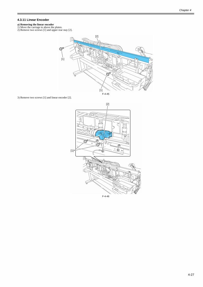
Chapter 4
4-27
4.3.11 Linear Encoder0014-8985
a) Removing the linear encoder1) Move the carriage to above the platen.2) Remove two screws [1] and upper rear stay [2].
F-4-453) Remove two screws [1] and linear encoder [2].
F-4-46
[1]
[1]
[2]
[1]
[2]

Chapter 4
4-28
4.3.12 Head Management Sensor0014-8988
a) Removing the head management sensor1) To remove head management sensor [1], remove screw [2] and disconnect connector [3].
F-4-47b) Action to take after replacing the head management sensor Because the distance between the head management sensor and the carriage unit is varied from one unit to another, the printer has its optical axis corrected to adjustthe non-discharging nozzle detection position prior to shipment. When the head management sensor carriage unit has been replaced, it should require adjustment.Execute service mode under the following conditions:SERVICE MODE > ADJUST > NOZZLE CHK POS.
[3]
[2]
[1]

Chapter 4
4-29
4.3.13 PCBs0023-3347
Do not replace the main controller PCB and the maintenance cartridge relay PCB (ROM board) at the same time.Both PCBs hold vital information, such as settings and a carriage drive time. Before either PCB is replaced, such information is temporarily saved through internalcommunication with the other PCB and is automatically written to the new PCB when it is installed. For this reason, the two PCBs cannot be replaced at the sametime. To replace both PCBs, work in order of (a) > (b).When the main controller PCB and maintenance cartridge relay PCB have been replaced with service parts, check that the latest version of firmware is installed inthem.If not, upgrade the firmware to the latest version.
Reference:For instruction on how to update the main controller, refer to "TROUBLESHOOTING" > "Version Up".
a) Replacing the maintenance cartridge relay PCB (ROM board)1) Turn off the power and disconnect the power plug.2) Replace the maintenance cartridge relay PCB.3) Reconnect the power plug and turn on the power while pressing the [Load] and [Navigate] keys. (Start the printer in PCB replacement mode.)4) Release the key, but not before making sure that "Initializing" appears on the display. (The message lamp lights when printer enters PCB replacement mode.)5) Wait until "REPLACE MODE" appears on the display.6) Select MC BOARD and press the [OK] key.7) Turn off the power, but not before making sure that "Power off" appears on the display.8) Turn on the power.9) Check the firmware version. If the firmware is not the latest version, upgrade the firmware to the latest version.
b) Replacing the main controller PCB1) Turn off the power and disconnect the power plug.2) Replace the main controller PCB.3) Reconnect the power plug and turn on the power while pressing the [Load] and [Navigate] keys. (Start the printer in PCB replacement mode.)4) Release the key, but not before making sure that "Initializing" appears on the display. (The message lamp lights when printer enters PCB replacement mode.)5) Wait until "REPLACE MODE" appears on the display.6) Select CPU BOARD and press the [OK] key.7) Turn off the power, but not before making sure that "Power off" appears on the display.8) Turn on the power.9) Check the firmware version. If the firmware is not the latest version, upgrade the firmware to the latest version.

Chapter 4
4-30
4.3.14 Opening the Cap/Moving the Wiper Unit0028-9713
This section explains how to open the cap and ink supply valve.To move the carriage with the power off, you need to release the carriage lock pin and cap.
a) Opening the Cap/Releasing the Carriage Lock Pin by service modeAfter entering the service mode, execute the following mode.Service mode: SERVICE MODE > FUNCTION > CR UNLOCK
b) Opening the Cap/Releasing the Carriage Lock Pin/Moving the Wiper Unit manually1) Remove right circle cover (L), right circle cover (S), right side cover and upper right cover.2) Insert a Phillips screwdriver from the right side into hole [1] in the shaft of the lift unit in the purge unit and turn it counterclockwise. This will lower cap [2] andlock pin [3], allowing the carriage to be moved.The wiper unit will move in sync with the motion of the cap and lock pin.
F-4-48
[1]
[3][2]

Chapter 4
4-31
4.3.15 Opening and closing ink supply valves0014-8992
a) Opening and closing ink supply valves
1) Remove the ink tank cover unit.2) Press valve lever [1] with a finger to open the ink supply valve.
F-4-49
- If the printhead fixer lever is released with the ink supply valve to an ink tube open while the tube is filled with an ink, the ink in the tube could flow backward tothe ink tank unit, leaking through the hollow needle in the ink tank.- If an ink supply valve remains open, as on occurrence of an ink supply valve open/close error, remove the valve motor unit and (see Disassembly/Reassembly >Points to Note on Disassembly/Reassembly > Ink Tank Units) and close the ink supply valve.
[1]

Chapter 4
4-32
4.3.16 Draining the ink0025-0404
There are two ways to drain the ink passage of inks: automatic and manual.
Be sure to drain the ink from the ink passage to prevent ink leakage before disassembling any component of the ink passage or reshipping the printer.
1. Automatic Ink DrainExecute Automatic Ink Drain by selecting [Set/Adj. Menu] > [Prep.MovePrinter] from the main menu.
Execute Automatic Ink Drain once again if the printer shuts down due to a power failure or any other trouble before the operation completes.
2. Manual ink drainageDrain the ink passage of inks manually if any electrical component in the printer fails or firmware malfunctions or if the printer fails to be powered on.1) Remove right circle cover (L), right circle cover (S), right side covers, left/ right the ink tank cover units. See Disassembly/Reassembly > Points to Note onDisassembly/Reassembly > External Covers.2) Remove the ink tanks.3) Move the carriage to above the platen. See Disassembly/Reassembly > Points to Note on Disassembly/Reassembly > Opening the caps and moving the wiper unit.4) Release the printhead fixer lever.5) Open the ink supply valves to allow the inks to flow into the subtanks.
3. Draining the ink in subtanks1) Remove the ink tank units. See Disassembly/Reassembly > Points to Note on Disassembly/Reassembly > Ink Tank Unit.2) Open the ink supply valve. See Disassembly/Reassembly > Points to Note on Disassembly/Reassembly > Opening and closing ink supply valves.3) Drain the ink in the subtank from the ink tube [1] to the container while inclining the ink tank unit to the rear slowly.
F-4-50
[1]

Chapter 4
4-33
4.4 Applying the Grease
4.4.1 Applying the Grease0014-9023
Some parts require application of grease when replaced. Apply the grease(special tool) listed below.Smear the grease lightly and evenly with a flat brush or the like.For the printer disassembly/reassembly method, refer to "DISASSEMBLY/REASSEMBLY" and "parts catalog".
Do not apply the grease to locations in which not designated grease may cause poor print quality. Take particular care that grease do not get onto the wiper, cap,carriage shaft and the linear scale.
1. The joint base rail [1] and the rib [2] of the carriage unit.
F-4-51
No. Location Grease Quantity Remarks1 The joint base rail and rib of carriage unit FLOIL G-5000H Smear the grease
lightly.2 Two feed roller backup FLOIL G-5000H Approx. 12mg Don't apply to central backup with
bearing.Bushing FLOIL G-5000H Smear the grease
lightly.3 Feed roller bearing FLOIL G-5000H Approx. 24mg Apply if remove bearing from a feed
roller.4 Pinch roller release cam three points x 10 parts FLOIL G-5000H Smear the grease
lightly.5 Upper cover stay shaft hole FLOIL G-5000H Approx. 24mg
The gear shaft of the upper cover stay gear FLOIL G-5000H Approx. 24mgUpper cover stay shaft end FLOIL G-5000H Approx. 24mgThe gear tooth face of upper cover stay FLOIL G-5000H Smear the grease
lightly.
[2]
[1][1]

Chapter 4
4-34
2. Two feed roller backup [1]/ bushing [2]3. Feed roller bearing [3]
F-4-524. Pinch roller release cam [1] three points x 10 parts
F-4-53
[1]
[2]
[3]
[1]

Chapter 4
4-35
5. Upper cover stay shaft hole [1]/ gear shaft [2]/ shaft end [3]/ gear tooth face [4]
F-4-54
[1]
[2] [4] [3]
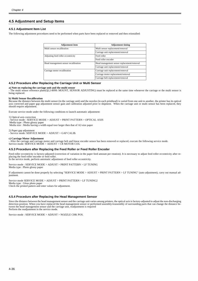
Chapter 4
4-36
4.5 Adjustment and Setup Items
4.5.1 Adjustment Item List0023-5489
The following adjustment procedures need to be performed when parts have been replaced or removed and then reinstalled:
4.5.2 Procedure after Replacing the Carriage Unit or Multi Sensor0025-0406
a) Note on replacing the carriage unit and the multi sensor- The multi sensor reference plate(QL2-8099: MOUNT, SENSOR ADJUSTING) must be replaced at the same time whenever the carriage or the multi sensor isbeing replaced.
b) Multi Sensor Recalibration Because the distance between the multi sensor (in the carriage unit) and the nozzles (in each printhead) is varied from one unit to another, the printer has its opticalaxis corrected and paper gap adjustment sensor gain and calibration adjusted prior to shipment. When the carriage unit or multi sensor has been replaced, theyshould require adjustment.
Execute service mode under the following conditions to launch automatic adjustment:
1) Optical axis correction - Service mode : SERVICE MODE > ADJUST > PRINT PATTERN > OPTICAL AXIS Media type : Photo glossy paper Media size : Media having a width equal toor larger then that of A2-size paper
2) Paper gap adjustment- Service mode: SERVICE MODE > ADJUST > GAP CALIB.
c) Carriage Motor Adjustment- After the carriage and carriage motor and carriage belt and linear encoder sensor has been removed or replaced, execute the following service mode.Service mode: SERVICE MODE > ADJUST > CR MOTOR COG
4.5.3 Procedure after Replacing the Feed Roller or Feed Roller Encoder0012-6594
Feed roller eccentricity is factory-adjusted (correction of variation in the paper feed amount per rotation). It is necessary to adjust feed roller eccentricity after re-placing the feed roller encoder or feed roller.In the service mode, perform automatic adjustment of feed roller eccentricity.
Service mode : SERVICE MODE > ADJUST > PRINT PATTERN > LF TUNINGMedia type : Photo glossy paper
If adjustment cannot be done properly by selecting "SERVICE MODE > ADJUST > PRINT PATTERN > LF TUNING" (auto adjustment), carry out manual ad-justment.
Service mode SERVICE MODE > ADJUST > PRINT PATTERN > LF TUNING2Media type: Gloss photo paperCheck the printed pattern and enter values for adjustment.
4.5.4 Procedure after Replacing the Head Management Sensor0013-7146
Since the distance between the head management sensor and the carriage unit varies among printers, the optical axis is factory-adjusted to adjust the non-dischargingdetection position. When you have replaced the head management sensor or performed assembly/reassembly of surrounding parts that can change the distance be-tween the head management sensor and the carriage unit, readjustment is requiredPerform the readjustment in the service mode.
Service mode : SERVICE MODE > ADJUST > NOZZLE CHK POS.
Adjustment item Adjustment timingMulti sensor recalibration Multi sensor replacement/removal
Carriage unit replacement/removalAdjusting feed roller eccentricity Feed roller
Feed roller encoderHead management sensor recalibration Head management sensor replacement/removal
Carriage unit replacement/removalCarriage motor recalibration Carriage unit replacement/removal
Carriage motor replacement/removalCarriage belt replacement/removal

Chapter 4
4-37


Chapter 5 MAINTENANCE


Contents
Contents
5.1 Periodic Replacement Parts ...........................................................................................................................................5-15.1.1 Periodic Replacement Parts ......................................................................................................................................................... 5-1
5.2 Consumable Parts...........................................................................................................................................................5-15.2.1 Consumable Parts......................................................................................................................................................................... 5-1
5.3 Periodic Maintenance.....................................................................................................................................................5-25.3.1 Periodic Maintenance................................................................................................................................................................... 5-2

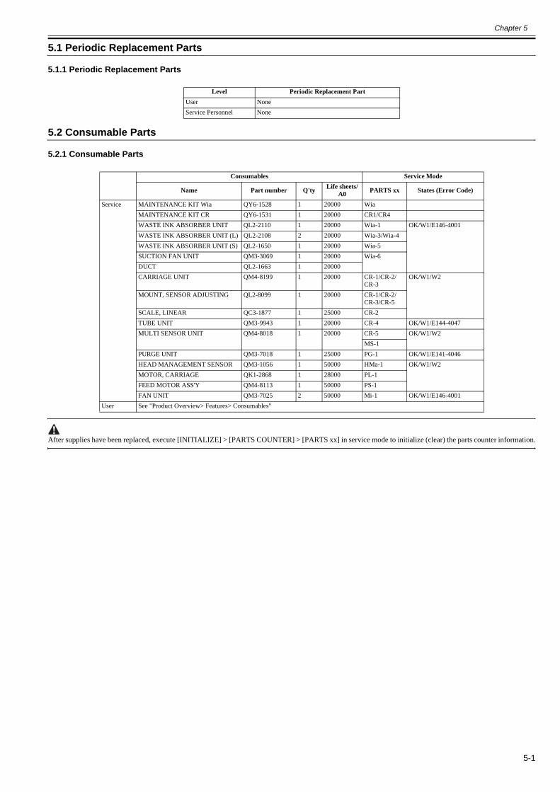
Chapter 5
5-1
5.1 Periodic Replacement Parts
5.1.1 Periodic Replacement Parts0012-6595
5.2 Consumable Parts
5.2.1 Consumable Parts0030-4814
After supplies have been replaced, execute [INITIALIZE] > [PARTS COUNTER] > [PARTS xx] in service mode to initialize (clear) the parts counter information.
Level Periodic Replacement PartUser NoneService Personnel None
Consumables Service Mode
Name Part number Q'ty Life sheets/A0 PARTS xx States (Error Code)
Service MAINTENANCE KIT Wia QY6-1528 1 20000 WiaMAINTENANCE KIT CR QY6-1531 1 20000 CR1/CR4WASTE INK ABSORBER UNIT QL2-2110 1 20000 Wia-1 OK/W1/E146-4001WASTE INK ABSORBER UNIT (L) QL2-2108 2 20000 Wia-3/Wia-4WASTE INK ABSORBER UNIT (S) QL2-1650 1 20000 Wia-5SUCTION FAN UNIT QM3-3069 1 20000 Wia-6DUCT QL2-1663 1 20000CARRIAGE UNIT QM4-8199 1 20000 CR-1/CR-2/
CR-3OK/W1/W2
MOUNT, SENSOR ADJUSTING QL2-8099 1 20000 CR-1/CR-2/CR-3/CR-5
SCALE, LINEAR QC3-1877 1 25000 CR-2TUBE UNIT QM3-9943 1 20000 CR-4 OK/W1/E144-4047MULTI SENSOR UNIT QM4-8018 1 20000 CR-5 OK/W1/W2
MS-1PURGE UNIT QM3-7018 1 25000 PG-1 OK/W1/E141-4046HEAD MANAGEMENT SENSOR QM3-1056 1 50000 HMa-1 OK/W1/W2MOTOR, CARRIAGE QK1-2868 1 28000 PL-1FEED MOTOR ASS'Y QM4-8113 1 50000 PS-1FAN UNIT QM3-7025 2 50000 Mi-1 OK/W1/E146-4001
User See "Product Overview> Features> Consumables"

Chapter 5
5-2
5.3 Periodic Maintenance
5.3.1 Periodic Maintenance0012-6597
a) Printer cleaningTo keep up with print quality and prevent troubles, clean the printer about once each month.
1) Using a damp cloth that you have wrung out completely, wipe away any dirt or paper dust from the Paper Feed Slot [1], power cord plug, and so on. Dry theseparts with a dry cloth.
F-5-12) Open the Top Cover.3) If paper dust has accumulated in the Vacuum holes on the Platen [1], the Borderless Printing Ink Grooves [2], or cutter guide [3], use the included Cleaning Brush[4] to wipe it away.
F-5-2
MEMO:If the Cleaning Brush is dirty, rinse it in water.
Level Periodic maintenanceUser Cleaning of ink mist and other substances(about once each monthService personnel None
[1]
[1]
[4]
[3][2]

Chapter 5
5-3
4) Using a damp cloth that you have wrung out completely, wipe inside the Top Cover to clean it. Wipe away any ink residue on the Top Cover Roller [1], all overthe Platen [2], the Pinch Roller Unit [3], the Borderless Printing Ink Grooves [4], the Ejection Guide [5], the cutter guide [6], the maintenance-jet tray [7], and so on.
F-5-3
[1]
[7]
[5]
[4]
[2] [4] [6] [3]

Chapter 5
5-4
- Do not dry the interiors of the top cover with a dry cloth. Electrostatic charges could make the internal components susceptible to dirt, resulting in degraded printquality.- Do not use flammable solvents, such as thinner and benzine, on the printer. Solvents coming into contact with any electrical parts inside the printer could resultin fires or electrical shock hazards.- Do not touch linear scale [1] and carriage shaft [2].
F-5-4
[1]
[2]

Chapter 6 TROUBLESHOOTING


Contents
Contents
6.1 Troubleshooting .............................................................................................................................................................6-16.1.1 Outline.......................................................................................................................................................................................... 6-1
6.1.1.1 Outline of Troubleshooting .............................................................................................................................................................................6-16.2 Location of Connectors and Pin Arrangement...............................................................................................................6-1
6.2.1 Main controller PCB .................................................................................................................................................................... 6-16.2.2 Carriage relay PCB .................................................................................................................................................................... 6-126.2.3 Head relay PCB.......................................................................................................................................................................... 6-21
6.3 Version Up ...................................................................................................................................................................6-296.3.1 Firmware Update Tool ............................................................................................................................................................... 6-29
6.4 Service Tools................................................................................................................................................................6-336.4.1 Tool List..................................................................................................................................................................................... 6-33


Chapter 6
6-1
6.1 Troubleshooting
6.1.1 Outline
6.1.1.1 Outline of Troubleshooting0013-1940
1. OutlineTroubles subject to troubleshooting are classified into those shown on the display (warning, error, and service call) and those not shown on the display.The code of warning and error is shown by combining alphanumeric characters of eight digits and four digits.The code of service call error is shown by the initial character of "E" and combining alphanumeric characters of three digits and four digits.No code number is displayed when a warning occurs. Selecting [SERVICE MODE] > [DISPLAY] > [WARNING] in service mode allows you to check the warninglog.
2. Precautions for Troubleshooting1) Check the environmental conditions and the media used for printing.2) Before performing troubleshooting, make sure that all connectors and cables are connected properly.3) When servicing the printer with the external cover removed and the AC power supplied, be extremely careful to avoid electric shock and shorting electricaldevices.4) In the following sections, the troubleshooting steps are described such that the component related to the most probable cause of the problem will be repaired orreplaced first, being followed by components with less problem probability. If multiple components have the same problem probability, the steps are describedbeginning with the easiest one.After performing each step, check to see if the problem has been resolved by making test prints. If the problem persists, proceed to the next step.5) After completion of the troubleshooting, check that all connectors and cables have been reconnected and screws have been tightened firmly.6) Whenever you have performed replacement or repair services, make test prints to check whether the problem has been resolved.
6.2 Location of Connectors and Pin Arrangement
6.2.1 Main controller PCB0025-0536
F-6-1T-6-1
T-6-2
J1001Pin Number Signal name IN/OUT Function1 VBUS IN USB VBUS(+5V)2 D- IN/OUT USB data(-)3 D+ IN/OUT USB data(+)4 AGND - USB GND5 FGND - GND (Connector shell)6 FGND - GND (Connector shell)
J1102Pin Number Signal name IN/OUT Function1 GND - GND2 GND - GND3 GND - GND4 +3.3V OUT Power supply(+3.3V)5 +3.3V OUT Power supply(+3.3V)6 +3.3V OUT Power supply(+3.3V)7 +3.3V OUT Power supply(+3.3V)8 +3.3V OUT Power supply(+3.3V)
1
1
1
1 1
1
1
J1001
J1201 J3301 J3002
J3201
J2502 J2702
J1102
J2701
J3501 J3601
J3502 J3602
J3401
J3150
J3001 J3003
J1801
J2801
J2501
J2601
J2402
J3910
1 1
1
1
1A1
B1
1
1
B1
A111
A1
B1
111
1
1
J1202

Chapter 6
6-2
9 +3.3V OUT Power supply(+3.3V)10 N.C. - N.C.11 GND - GND12 /PME IN Power management enable signal13 /INTA IN Interrupt signal14 GND - GND15 /RST OUT PCI Reset signal16 CLK OUT PCI Clock signal17 /GNT OUT Ground signal18 GND - GND19 /REQ IN Request signal20 AD31 IN/OUT Address and data signal21 AD30 IN/OUT Address and data signal22 AD29 IN/OUT Address and data signal23 AD28 IN/OUT Address and data signal24 GND - GND25 AD27 IN/OUT Address and data signal26 AD26 IN/OUT Address and data signal27 AD25 IN/OUT Address and data signal28 AD24 IN/OUT Address and data signal29 /CBE3 IN/OUT Bus command and byte enable signal30 IDSEL OUT Inisharaization device select signal31 GND - GND32 GND - GND33 AD23 IN/OUT Address and data signal34 AD22 IN/OUT Address and data signal35 AD21 IN/OUT Address and data signal36 AD20 IN/OUT Address and data signal37 GND - GND38 AD19 IN/OUT Address and data signal39 AD18 IN/OUT Address and data signal40 AD17 IN/OUT Address and data signal41 AD16 IN/OUT Address and data signal42 /CBE2 OUT Bus command and byte enable signal43 GND - GND44 /FRAME IN/OUT Cycle frame signal45 /IRDY IN/OUT Initiator ready signal46 /TRDY IN/OUT Target ready signal47 /DEVSEL IN/OUT Device select signal48 GND - GND49 /STOP IN/OUT Stop signal50 /LOCK IN/OUT Lock signal51 /PERP IN/OUT Parity error signal52 /SERR IN/OUT System error signal53 PAR IN/OUT Parity signal54 /CBE1 IN/OUT Bus command and byte enable signal55 GND - GND56 GND - GND57 AD15 IN/OUT Address and data signal58 AD14 IN/OUT Address and data signal59 AD13 IN/OUT Address and data signal60 AD12 IN/OUT Address and data signal61 GND - GND62 AD11 IN/OUT Address and data signal63 AD10 IN/OUT Address and data signal64 AD9 IN/OUT Address and data signal65 AD8 IN/OUT Address and data signal66 /CBE0 IN/OUT Bus command and byte enable signal67 GND - GND68 AD7 IN/OUT Address and data signal69 AD6 IN/OUT Address and data signal70 AD5 IN/OUT Address and data signal71 AD4 IN/OUT Address and data signal72 GND - GND73 AD3 IN/OUT Address and data signal
J1102Pin Number Signal name IN/OUT Function

Chapter 6
6-3
T-6-3
T-6-4
T-6-5
T-6-6
74 AD2 IN/OUT Address and data signal75 AD1 IN/OUT Address and data signal76 AD0 IN/OUT Address and data signal77 GND - GND78 HDD_LED - N.C.79 +5V OUT Power supply(+5V)80 +5V OUT Power supply(+5V)81 +5V OUT Power supply(+5V)82 +3.3V OUT Power supply(+3.3V)83 +3.3V OUT Power supply(+3.3V)84 +3.3V OUT Power supply(+3.3V)85 GND - GND86 GND - GND87 GND - GND88 GND - GND
J1201Pin Number Signal name IN/OUT Function1 GND - GND2 TXP OUT Transmission Data3 TXN OUT Transmission Data4 GND - GND5 RXN IN Receive Data6 RXP IN Receive Data7 GND - GND
J1202Pin Number Signal name IN/OUT Function1 DASPN IN Access signal2 +5V IN Power supply(+5V)3 GND - GND
J1801Pin Number Signal name IN/OUT Function1 RGV20(+5V) IN Power supply(+5V)2 RGV20(+5V) IN Power supply(+5V)3 RGV20(+5V) IN Power supply(+5V)4 GND - GND5 GND - GND6 GND - GND7 VM IN Power supply(+32V)8 VM IN Power supply(+32V)9 VMGND - GND10 VMGND - GND11 VM_ENB OUT VM enable signal12 AFCONT OUT Normal/Power saving switch signal
J2402Pin Number Signal name IN/OUT Function1 INKBENM2_AM OUT Left valve motor drive signal AM2 INKBENM2_AP OUT Left valve motor drive signal AP3 SNS3V OUT Power supply(+3.3V)4 GND - GND5 /INKBEN_OPEN_L IN Left valve open/close detection sensor output signal6 /TANK_COVER_L IN Left ink tank cover switch output signal7 GND - GND8 SNS3V OUT Power supply(+3.3V)9 GND - GND10 /INKBEN_CAM_L IN Left ink tank agitation cam sensor output signal
J1102Pin Number Signal name IN/OUT Function

Chapter 6
6-4
T-6-7
T-6-8
T-6-9
11 N.C - N.C
J2501Pin Number Signal name IN/OUT FunctionA1 N.C - N.CA2 N.C - N.CA3 N.C - N.CA4 SNS3V OUT Power supply(+3.3V)A5 GND - GNDA6 /CR_HP IN Lift cam sensor output signalA7 OUT_LIFTM_VM OUT Power supplyA8 OUT_LIFTM0_A OUT Lift motor drive signal AA9 OUT_LIFTM2_AX_N0 OUT Lift motor drive signal AXA10 OUT_LIFTM1_B OUT Lift motor drive signal BA11 OUT_LIFTM3_BX_N1 OUT Lift motor drive signal BXA12 /ATUKAIJO_IN IN Pressure release switch output signalA13 GND - GNDB1 PUMPM1_AM OUT Purge motor drive signal AMB2 PUMPM1_AP OUT Purge motor drive signal APB3 GND - GNDB4 PUMPR_ENCA IN Pump encoder sensor output signal AB5 SNS5V OUT Power supply(+5V)B6 PUMPR_ENCB IN Pump encoder sensor output signal BB7 SNS3V OUT Power supply(+3.3V)B8 GND - GNDB9 /CONTROL_CAM_R IN Pump cam sensor output signalB10 GND - GNDB11 /MEDIA_R IN Media sensor output signalB12 SNS5V OUT Power supply(+5V)B13 N.C - N.C
J2502Pin Number Signal name IN/OUT Function1 INKBENM1_AM OUT Right valve motor drive signal AM2 INKBENM1_AP OUT Right valve motor drive signal AP3 SNS3V OUT Power supply(+3V)4 GND - GND5 /INKBEN_OPEN_R IN Right valve open/close detection sensor output signal6 /TANK_COVER_R IN Right ink tank cover switch output signal7 GND - GND8 SNS3V OUT Power supply(+3V)9 GND - GND10 /INKBEN_CAM_R IN Right ink tank agitation cam sensor output signal
J2601Pin Number Signal name IN/OUT Function1 POWER_ON IN Power switch signal2 GND - GND3 RGV20(+5V) OUT Power supply(+5V)4 BUZZER OUT Buzzer control signal5 PDO OUT Panel IC control signal6 RGV29(+5V) OUT Power supply(+5V)7 PDI OUT Panel IC data signal8 HDD_LED OUT HDD lamp control signal9 /PRESET OUT Panel reset signal10 GND - GND11 PCK OUT Panel IC clock signal12 PANEL_5V OUT Power supply(+5V)13 /PCS OUT Panel IC chip select signal
J2402Pin Number Signal name IN/OUT Function
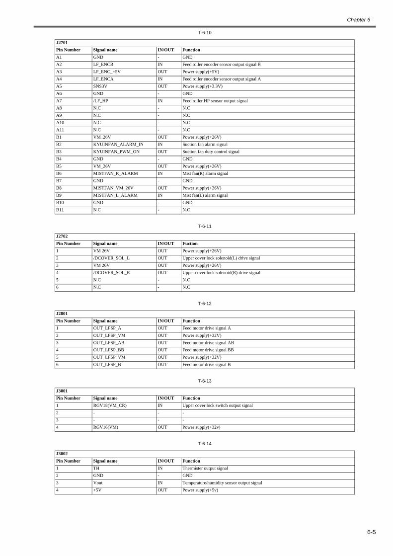
Chapter 6
6-5
T-6-10
T-6-11
T-6-12
T-6-13
T-6-14
J2701Pin Number Signal name IN/OUT FunctionA1 GND - GNDA2 LF_ENCB IN Feed roller encoder sensor output signal BA3 LF_ENC_+5V OUT Power supply(+5V)A4 LF_ENCA IN Feed roller encoder sensor output signal AA5 SNS3V OUT Power supply(+3.3V)A6 GND - GNDA7 /LF_HP IN Feed roller HP sensor output signalA8 N.C - N.CA9 N.C - N.CA10 N.C - N.CA11 N.C - N.CB1 VM_26V OUT Power supply(+26V)B2 KYUINFAN_ALARM_IN IN Suction fan alarm signalB3 KYUINFAN_PWM_ON OUT Suction fan duty control signalB4 GND - GNDB5 VM_26V OUT Power supply(+26V)B6 MISTFAN_R_ALARM IN Mist fan(R) alarm signalB7 GND - GNDB8 MISTFAN_VM_26V OUT Power supply(+26V)B9 MISTFAN_L_ALARM IN Mist fan(L) alarm signalB10 GND - GNDB11 N.C - N.C
J2702Pin Number Signal name IN/OUT Fuction1 VM 26V OUT Power supply(+26V)2 /DCOVER_SOL_L OUT Upper cover lock solenoid(L) drive signal3 VM 26V OUT Power supply(+26V)4 /DCOVER_SOL_R OUT Upper cover lock solenoid(R) drive signal5 N.C - N.C6 N.C - N.C
J2801Pin Number Signal name IN/OUT Function1 OUT_LFSP_A OUT Feed motor drive signal A2 OUT_LFSP_VM OUT Power supply(+32V)3 OUT_LFSP_AB OUT Feed motor drive signal AB4 OUT_LFSP_BB OUT Feed motor drive signal BB5 OUT_LFSP_VM OUT Power supply(+32V)6 OUT_LFSP_B OUT Feed motor drive signal B
J3001Pin Number Signal name IN/OUT Function1 RGV18(VM_CR) IN Upper cover lock switch output signal2 - - -3 - - -4 RGV16(VM) OUT Power supply(+32v)
J3002Pin Number Signal name IN/OUT Function1 TH IN Thermister output signal2 GND - GND3 Vout IN Temperature/humidity sensor output signal4 +5V OUT Power supply(+5v)

Chapter 6
6-6
T-6-15
T-6-16
T-6-17
J3003Pin Number Signal name IN/OUT Function1 /MAKITORI_UNIT IN Media take-up paper detection sensor2 /MAKITORI_LOCK_SENS IN Media take-up on/off sensor output signal3 /MAKITORI_VCC_ON OUT Power supply ON signal4 MAKITORI_VM_ON OUT Power supply(+26V)5 /MAKITORI_ENB OUT Media take-up drive enable signal6 PHOTO_SENS_OUT IN Media take-up paper detection sensor output signal7 VM_26V OUT Power supply(+26V)8 VM_26V OUT Power supply(+26V)9 VMGND - GND10 VMGND - GND11 +5V OUT Power supply(+5V)12 N.C. - N.C13 N.C. - N.C14 N.C. - N.C
J3150Pin Number Signal name IN/OUT Function1 IN 3+ IN Hole sensor input signal 3+2 IN 3- IN Hole sensor input signal 3-3 IN 1- IN Hole sensor input signal 1-4 IN 2+ IN Hole sensor input signal 2+5 IN 1+ IN Hole sensor input signal 1+6 IN 2- IN Hole sensor input signal 2-7 VM_GND - GND8 +5V OUT Power supply (+5V)9 OUT B OUT Motor output signal B10 OUT B OUT Motor output signal B11 OUT A OUT Motor output signal A12 OUT A OUT Motor output signal A13 OUT C OUT Motor output signal C14 OUT C OUT Motor output signal C
J3201Pin Number Signal name IN/OUT FunctionA1 TANK_CLK OUT Ink tank clock signalA2 GND - GNDA3 OUT_TANK_DAT2 IN/OUT Ink tank data signal 2A4 TANK_+3.3V OUT Power supply(+3.3V)A5 OUT_TANK_DAT1 IN/OUT Ink tank data signal 1A6 OUT_TANK_DAT0 IN/OUT Ink tank data signal 0A7 GND - GNDA8 OUT_INK_DETECT0 IN Ink detection sensor output signal 0A9 OUT_INK_DETECT1 IN Ink detection sensor output signal 1A10 OUT_INK_DETECT2 IN Ink detection sensor output signal 2A11 OUT_TANK_DAT5 IN/OUT Ink tank data signal 5A12 OUT_TANK_DAT4 IN/OUT Ink tank data signal 4A13 OUT_TANK_DAT3 IN/OUT Ink tank data signal 3A14 OUT_INK_DETECT3 IN Ink detection sensor output signal 3A15 OUT_INK_DETECT4 IN Ink detection sensor output signal 4A16 OUT_INK_DETECT5 IN Ink detection sensor output signal 5A17 GND - GNDB1 TANK_CLK OUT Ink tank clock signalB2 GND - GNDB3 OUT_TANK_DAT8 IN/OUT Ink tank data signal 8B4 TANK_+3.3V OUT Power supply(+3.3V)B5 OUT_TANK_DAT7 IN/OUT Ink tank data signal 7B6 OUT_TANK_DAT6 IN/OUT Ink tank data signal 6B7 GND - GNDB8 OUT_INK_DETECT6 IN Ink detection sensor output signal 6B9 OUT_INK_DETECT7 IN Ink detection sensor output signal 7B10 OUT_INK_DETECT8 IN Ink detection sensor output signal 8

Chapter 6
6-7
T-6-18
T-6-19
T-6-20
B11 OUT_TANK_DAT11 IN/OUT Ink tank data signal 11B12 OUT_TANK_DAT10 IN/OUT Ink tank data signal 10B13 OUT_TANK_DAT9 IN/OUT Ink tank data signal 9B14 OUT_INK_DETECT9 IN Ink detection sensor output signal 9B15 OUT_INK_DETECT10 IN Ink detection sensor output signal 10B16 OUT_INK_DETECT11 IN Ink detection sensor output signal 11B17 n.c - n.c
J3301Pin Number Signal name IN/OUT Function1 MENT_SDA IN/OUT Maintenance cartridge ROM control signal (data)2 MENT_SCL IN/OUT Maintenance cartridge ROM control signal (clock)3 GND - GND4 +3.3V OUT Power supply (+3.3V)5 GND - GND6 /FUTO_CLMP OUT Head management sensor clamp signal7 /FUTO_ON OUT Head management sensor ON signal8 SNS5V OUT Power supply(+5V)9 /FUTO_CMP IN Head management sensor ink detection signal
J3401Pin Number Signal name IN/OUT Function1 VMGND - GND2 VMGND - GND3 VMGND - GND4 VH_MONI1 IN VH controll signal 15 VH_MONI3 IN VH controll signal 36 VMGND - GND7 VM_26V OUT Power supply(+26V)8 GND - GND9 +3.3V OUT Power supply(+3.3V)10 +3.3V OUT Power supply(+3.3V)11 GND - GND12 SNS5V OUT Power supply(+5V)13 SNS5V OUT Power supply(+5V)14 VM OUT Power supply(+32V)15 VM OUT Power supply(+32V)16 VM OUT Power supply(+32V)17 VM OUT Power supply(+32V)18 VM OUT Power supply(+32V)19 VM OUT Power supply(+32V)20 VM OUT Power supply(+32V)21 VM OUT Power supply(+32V)22 VMGND - GND23 VMGND - GND24 VMGND - GND25 VMGND - GND
J3501Pin Number Signal name IN/OUT Function1 GND - GND2 H1-C-DATA-4-OD_OUT OUT Odd head(L) data signal 4(C)3 GND - GND4 H1-A-DATA-1-OD_OUT OUT Odd head(L) data signal 1(A)5 GND - GND6 H1-B-HE-2_B OUT Head(L) heat enable signal 2(B)7 GND - GND8 H0-D-DATA-7-OD_B OUT Odd head(R) data signal 7(D)9 GND - GND10 H0-E-HE-8_B OUT Head(R) heat enable signal 8(E)11 GND - GND
J3201Pin Number Signal name IN/OUT Function

Chapter 6
6-8
T-6-21
12 H0-E-DATA-8-OD_B OUT Odd head(R) data signal 8(E)13 GND - GND14 H0-F-DATA-10-OD OUT Odd head(R) data signal 10(F)15 GND - GND16 H0-E-DATA-9-OD_B OUT Odd head(R) data signal 9(E)17 GND - GND18 H0-F-HE-10_B OUT Head(R) heat enable signal 10(F)19 GND - GND20 H0-F-DATA-11-OD OUT Odd head(R) data signal 11(F)21 GND - GND22 H0-F-HE-11_B OUT Head(R) heat enable signal 11(F)23 GND - GND24 H0-F-DATA-11-EV_B OUT Even head(R) data signal 11(F)25 GND - GND26 H0-F-DATA-10-EV_B OUT Even head(R) data signal 10(F)27 GND - GND28 H0-E-HE-9_B OUT Head(R) heat enable signal 9(E)29 GND - GND30 H0-E-DATA-9-EV_B OUT Even head(R) data signal 9(E)31 GND - GND32 H-DASH_LICC2_B OUT Head analogue switch A/D trigger signal33 GND - GND34 H0-A-DATA-0-OD_B OUT Odd head(R) data signal 0(A)35 GND - GND36 H0-A-DATA-1-OD_B OUT Odd head(R) data signal 1(A)37 GND - GND38 H0-B-HE-2_B OUT Head(R) heat enable signal 2(B)39 GND - GND40 H0-B-DATA-2-OD_B OUT Odd head(R) data signal 2(B)41 GND - GND42 H0-B-DATA-3-OD_B OUT Odd head(R) data signal 3(B)43 GND - GND44 H0-C-HE-4_B OUT Head(R) heat enable signal 4(C)45 GND - GND46 H0-C-DATA-4-OD_B OUT Odd head(R) data signal 4(C)47 GND - GND48 H0-A-HE-0_B OUT Head(R) heat enable signal 0(A)49 GND - GND50 VHT_MONI IN VHT controll signal
J3502Pin Number Signal name IN/OUT Function1 GND - GND2 H0-E-DATA-8-EV_B OUT Even head(R) data signal 8(E)3 OUT_ENB OUT Head data enable signal4 H0-D-HE-7_B OUT Head(R) heat enable signal 7(D)5 GND - GND6 H0-D-DATA-7-EV_B OUT Even head(R) data signal 7(D)7 GND - GND8 H0-D-DATA-6-EV_B OUT Even head(R) data signal 6(D)9 GND - GND10 H0-D-DATA-6-OD_B OUT Odd head(R) data signal 6(D)11 GND - GND12 H0-D-HE-6_B OUT Head(R) heat enable signal 6(D)13 GND - GND14 H0-C-HE-5_B OUT Head(R) heat enable signal 5(C)15 GND - GND16 H0-C-DATA-5-OD_B OUT Odd head(R) data signal 5(C)17 GND - GND18 H0-DSOUT2 OUT Head(R) temperature output signal 219 GND - GND20 H0-DSOUT1 OUT Head(R) temperature output signal 121 GND - GND22 H0-DLD_LICC2 OUT Head(R) analogue switch latch signal
J3501Pin Number Signal name IN/OUT Function

Chapter 6
6-9
T-6-22
23 H0-DATA_LICC2 OUT Head(R) analogue switch data signal24 H0-DASLK_LICC2 OUT Head(R) analogue switch clock signal25 GND - GND26 H0_CLK_B OUT Head(R) clock signal27 GND - GND28 H0_LT_B OUT Head(R) latch signal29 GND - GND30 H0-C-DATA-5-EV_B OUT Even head(R) data signal 5(C)31 GND - GND32 LIFT_CAM_IN IN Lift cam sensor output signal33 GND - GND34 H0-B-HE-3_B OUT Head(R) heat enable signal 3(B)35 GND - GND36 H0-C-DATA-4-EV_B OUT Even head(R) data signal 4(C)37 GND - GND38 H0-B-DATA-3-EV_B OUT Even head(R) data signal 3(B)39 GND - GND40 H0-B-DATA-2-EV_B OUT Even head(R) data signal 2(B)41 GND - GND42 H0-A-DATA-1-EV_B OUT Even head(R) data signal 1(A)43 GND - GND44 H0-A-HE-1_B OUT Head(R) heat enable signal 1(A)45 GND - GND46 H0-A-DATA-0-EV_B OUT Even head(R) data signal 0(A)47 GND - GND48 VH_CHARGE0 OUT VH leakage detection ON/OFF signal 049 VH_CHARGE1 OUT VH leakage detection ON/OFF signal 150 GND - GND
J3601Pin Number Signal name IN/OUT Function1 GND - GND2 ENCODER_B IN Carriage encoder output signal B3 ENCODER_A IN Carriage encoder output signal A4 /CR_COVER IN Carriage cover sensor output signal5 GND - GND6 H-DASH_LICC2_B OUT Head analogue switch A/D trigger signal7 GND - GND8 H1-D-DATA-7-OD_B OUT Odd head(R) data signal 7(D)9 GND - GND10 /H1-E-HE-8_B OUT Head(R) heat enable signal 8(E)11 GND - GND12 H1-E-DATA-8-OD_B OUT Odd head(R) data signal 8(E)13 GND - GND14 H1-F-DATA-10-OD_B OUT Odd head(R) data signal 10(F)15 GND - GND16 H1-E-DATA-9-OD_B OUT Odd head(R) data signal 9(E)17 GND - GND18 /H1-F-HE-10_B OUT Head(R) heat enable signal 10(F)19 GND - GND20 /H1-F-DATA-11-OD_B OUT Odd head(R) data signal 11(F)21 GND - GND22 H1-F-HE-11_B OUT Head(R) heat enable signal 11(F)23 GND - GND24 H1-F-DATA-11-EV_B OUT Even head(R) data signal 11(F)25 GND - GND26 H1-F-DATA-10-EV_B OUT Even head(R) data signal 10(F)27 GND - GND28 /H1-E-HE-9_B OUT Head(R) heat enable signal 9(E)29 GND - GND30 H1-E-DATA-9-EV_B OUT Even head(R) data signal 9(E)31 GND - GND32 VH_DIS OUT VH selection signal33 H1-DASLK_LICC2 OUT Head(R) analogue switch clock signal
J3502Pin Number Signal name IN/OUT Function

Chapter 6
6-10
T-6-23
34 H1-DLD_LICC2 OUT Head(R) analogue switch latch signal35 H1-DATA_LICC2 OUT Head(R) analogue switch data signal36 PWLED2_ON OUT Multi sensor LED2 drive signal37 PWLED1_ON OUT Multi sensor LED1 drive signal38 PWLED3_ON OUT Multi sensor LED3 drive signal39 H3V_ON OUT Power supply40 MLT_SENS_1IN IN Multi sensor signal 141 MLT_SENS_2IN IN Multi sensor signal 242 PWLED4_ON OUT Multi sensor LED4 drive signal43 GND - GND44 H1-B-DATA-2-OD_B OUT Odd head(R) data signal 2(B)45 GND - GND46 H1-B-DATA-3-OD_B OUT Odd head(R) data signal 1(B)47 GND - GND48 /H1-C-HE-4_B OUT Head(R) heat enable signal 4(C)49 GND - GND50 GND - GND
J3602Pin Number Signal name IN/OUT Function1 GND - GND2 IO-ASIC_SCL_B IN/OUT Head ROM controll signal(clock)3 IO-ASIC_SDA IN/OUT Head ROM controll signal(data)4 GND - GND5 H1-DSOUT1 OUT Head temperature output signal 16 H1-DSOUT2 OUT Head temperature output signal 27 GND - GND8 H1-E-DATA-8-EV_B OUT Even head(L) data signal 8(E)9 GND - GND10 /H1-D-HE-7_B OUT Head(L) heat enable signal 7(D)11 GND - GND12 H1-D-DATA-7-EV_B OUT Even head(L) data signal 7(D)13 GND - GND14 H1-D-DATA-6-EV_B OUT Even head(L) data signal 6(D)15 GND - GND16 H1-D-DATA-6-OD_B OUT Odd head(L) data signal 6(D)17 GND - GND18 /H1-D-HE-6_B OUT Head(L) heat enable signal 6(D)19 GND - GND20 /H1-C-HE-5_B OUT Head(L) heat enable signal 5(C)21 GND - GND22 H1-C-DATA-5-OD_B OUT Odd head(L) data signal 5(C)23 GND - GND24 H1_CLK OUT Head(L) clock signal25 GND - GND26 /H1_LT_B OUT Head(L) latch signal27 GND - GND28 H1-C-DATA-5-EV_B OUT Even head(L) data signal 5(C)29 GND - GND30 /H1-B-HE-3_B OUT Head(L) heat enable signal 3(B)31 GND - GND32 H1-C-DATA-4-EV_B OUT Even head(L) data signal 4(C)33 GND - GND34 H1-B-DATA-3-EV_B OUT Even head(L) data signal 3(B)35 GND - GND36 H1-B-DATA-2-EV_B OUT Even head(L) data signal 2(B)37 GND - GND38 H1-A-DATA-1-EV_B OUT Even head(L) data signal 1(A)39 GND - GND40 /H1-A-HE-1_B OUT Head(L) heat enable signal 1(A)41 GND - GND42 H1-A-DATA-0-EV_B OUT Even head(L) data signal 0(A)43 GND - GND44 /H1-A-HE-0_B OUT Head(L) heat enable signal 0(A)
J3601Pin Number Signal name IN/OUT Function

Chapter 6
6-11
45 GND - GND46 H1-A-DATA-0-OD_B OUT Odd head(L) data signal 0(A)47 GND - GND48 VHT_ENB OUT VHT enable signal49 HV_ENB OUT HV enable signal50 FFC_SLANT_DET_SNS - -
J3602Pin Number Signal name IN/OUT Function

Chapter 6
6-12
6.2.2 Carriage relay PCB0025-0539
F-6-2T-6-24
T-6-25
J101Pin Number Signal name IN/OUT Function1 VMGND - GND2 VMGND - GND3 VMGND - GND4 VMGND - GND5 VM OUT Power supply(+32V)6 VM OUT Power supply(+32V)7 VM OUT Power supply(+32V)8 VM OUT Power supply(+32V)9 VM OUT Power supply(+32V)10 VM OUT Power supply(+32V)11 VM OUT Power supply(+32V)12 VM OUT Power supply(+32V)13 SNS5V OUT Power supply(+5V)14 SNS5V OUT Power supply(+5V)15 GND - GND16 +3.3V OUT Power supply(+3.3V)17 +3.3V OUT Power supply(+3.3V)18 GND - GND19 VM_26V OUT Power supply(+26V)20 VMGND - GND21 VH_MONI3 IN VH controll signal 322 VH_MONI1 IN VH controll signal 123 VMGND - GND24 VMGND - GND25 VMGND - GND
J102Pin Number Signal name IN/OUT Function1 GND - GND2 GND - GND3 /H1-C-HE-4_B OUT Head(R) heat enable signal 4(C)4 GND - GND5 H1-B-DATA-3-OD_B OUT Odd head(R) data signal 1(B)6 GND - GND7 H1-B-DATA-2-OD_B OUT Odd head(R) data signal 2(B)8 GND - GND9 PWLED4_ON OUT Multi sensor LED4 drive signal10 MLT_SENS_2IN IN Multi sensor signal 211 MLT_SENS_1IN IN Multi sensor signal 112 H3V_ON OUT Power supply13 PWLED3_ON OUT Multi sensor LED3 drive signal14 PWLED1_ON OUT Multi sensor LED1 drive signal15 PWLED2_ON OUT Multi sensor LED2 drive signal16 H1-DATA_LICC2 OUT Head(R) analogue switch data signal
J105 J104 J101 J102 J103J201
J703
J702
J701
J803
J802
J801
1
1
1
1
1
1
11
1
111
J105 J104 J101 J102 J103J201
J703
J702
J701
J803
J802
J801
1
1
1
1
1
1
11
1
111
1J202

Chapter 6
6-13
T-6-26
17 H1-DLD_LICC2 OUT Head(R) analogue switch latch signal18 H1-DASLK_LICC2 OUT Head(R) analogue switch clock signal19 VH_DIS OUT VH selection signal20 GND - GND21 H1-E-DATA-9-EV_B OUT Even head(R) data signal 9(E)22 GND - GND23 /H1-E-HE-9_B OUT Head(R) heat enable signal 9(E)24 GND - GND25 H1-F-DATA-10-EV_B OUT Even head(R) data signal 10(F)26 GND - GND27 H1-F-DATA-11-EV_B OUT Even head(R) data signal 11(F)28 GND - GND29 H1-F-HE-11_B OUT Head(R) heat enable signal 11(F)30 GND - GND31 /H1-F-DATA-11-OD_B OUT Odd head(R) data signal 11(F)32 GND - GND33 /H1-F-HE-10_B OUT Head(R) heat enable signal 10(F)34 GND - GND35 H1-E-DATA-9-OD_B OUT Odd head(R) data signal 9(E)36 GND - GND37 H1-F-DATA-10-OD_B OUT Odd head(R) data signal 10(F)38 GND - GND39 H1-E-DATA-8-OD_B OUT Odd head(R) data signal 8(E)40 GND - GND41 /H1-E-HE-8_B OUT Head(R) heat enable signal 8(E)42 GND - GND43 H1-D-DATA-7-OD_B OUT Odd head(R) data signal 7(D)44 GND - GND45 H-DASH_LICC2_B OUT Head analogue switch A/D trigger signal46 GND - GND47 /CR_COVER IN Carriage cover sensor output signal48 ENCODER_A IN Carriage encoder output signal A49 ENCODER_B IN Carriage encoder output signal B50 GND - GND
J103Pin Number Signal name IN/OUT Function1 FFC_SLANT_DET_SNS - -2 HV_ENB OUT HV enable signal3 VHT_ENB OUT VHT enable signal4 GND - GND5 H1-A-DATA-0-OD_B OUT Odd head(L) data signal 0(A)6 GND - GND7 /H1-A-HE-0_B OUT Head(L) heat enable signal 0(A)8 GND - GND9 H1-A-DATA-0-EV_B OUT Even head(L) data signal 0(A)10 GND - GND11 /H1-A-HE-1_B OUT Head(L) heat enable signal 1(A)12 GND - GND13 H1-A-DATA-1-EV_B OUT Even head(L) data signal 1(A)14 GND - GND15 H1-B-DATA-2-EV_B OUT Even head(L) data signal 2(B)16 GND - GND17 H1-B-DATA-3-EV_B OUT Even head(L) data signal 3(B)18 GND - GND19 H1-C-DATA-4-EV_B OUT Even head(L) data signal 4(C)20 GND - GND21 /H1-B-HE-3_B OUT Head(L) heat enable signal 3(B)22 GND - GND23 H1-C-DATA-5-EV_B OUT Even head(L) data signal 5(C)24 GND - GND25 /H1_LT_B OUT Head(L) latch signal26 GND - GND27 H1_CLK OUT Head(L) clock signal
J102Pin Number Signal name IN/OUT Function

Chapter 6
6-14
T-6-27
28 GND - GND29 H1-C-DATA-5-OD_B OUT Odd head(L) data signal 5(C)30 GND - GND31 /H1-C-HE-5_B OUT Head(L) heat enable signal 5(C)32 GND - GND33 /H1-D-HE-6_B OUT Head(L) heat enable signal 6(D)34 GND - GND35 H1-D-DATA-6-OD_B OUT Odd head(L) data signal 6(D)36 GND - GND37 H1-D-DATA-6-EV_B OUT Even head(L) data signal 6(D)38 GND - GND39 H1-D-DATA-7-EV_B OUT Even head(L) data signal 7(D)40 GND - GND41 /H1-D-HE-7_B OUT Head(L) heat enable signal 7(D)42 GND - GND43 H1-E-DATA-8-EV_B OUT Even head(L) data signal 8(E)44 GND - GND45 H1-DSOUT2 OUT Head temperature output signal 246 H1-DSOUT1 OUT Head temperature output signal 147 GND - GND48 IO-ASIC_SDA IN/OUT Head ROM controll signal(data)49 IO-ASIC_SCL_B IN/OUT Head ROM controll signal(clock)50 GND - GND
J104Pin Number Signal name IN/OUT Function1 VHT_MONI IN VHT controll signal2 GND - GND3 H0-A-HE-0_B OUT Head(R) heat enable signal 0(A)4 GND - GND5 H0-C-DATA-4-OD_B OUT Odd head(R) data signal 4(C)6 GND - GND7 H0-C-HE-4_B OUT Head(R) heat enable signal 4(C)8 GND - GND9 H0-B-DATA-3-OD_B OUT Odd head(R) data signal 3(B)10 GND - GND11 H0-B-DATA-2-OD_B OUT Odd head(R) data signal 2(B)12 GND - GND13 H0-B-HE-2_B OUT Head(R) heat enable signal 2(B)14 GND - GND15 H0-A-DATA-1-OD_B OUT Odd head(R) data signal 1(A)16 GND - GND17 H0-A-DATA-0-OD_B OUT Odd head(R) data signal 0(A)18 GND - GND19 H-DASH_LICC2_B OUT Head analogue switch A/D trigger signal20 GND - GND21 H0-E-DATA-9-EV_B OUT Even head(R) data signal 9(E)22 GND - GND23 H0-E-HE-9_B OUT Head(R) heat enable signal 9(E)24 GND - GND25 H0-F-DATA-10-EV_B OUT Even head(R) data signal 10(F)26 GND - GND27 H0-F-DATA-11-EV_B OUT Even head(R) data signal 11(F)28 GND - GND29 H0-F-HE-11_B OUT Head(R) heat enable signal 11(F)30 GND - GND31 H0-F-DATA-11-OD OUT Odd head(R) data signal 11(F)32 GND - GND33 H0-F-HE-10_B OUT Head(R) heat enable signal 10(F)34 GND - GND35 H0-E-DATA-9-OD_B OUT Odd head(R) data signal 9(E)36 GND - GND37 H0-F-DATA-10-OD OUT Odd head(R) data signal 10(F)38 GND - GND
J103Pin Number Signal name IN/OUT Function

Chapter 6
6-15
T-6-28
39 H0-E-DATA-8-OD_B OUT Odd head(R) data signal 8(E)40 GND - GND41 H0-E-HE-8_B OUT Head(R) heat enable signal 8(E)42 GND - GND43 H0-D-DATA-7-OD_B OUT Odd head(R) data signal 7(D)44 GND - GND45 H1-B-HE-2_B OUT Head(L) heat enable signal 2(B)46 GND - GND47 H1-A-DATA-1-OD_OUT OUT Odd head(L) data signal 1(A)48 GND - GND49 H1-C-DATA-4-OD_OUT OUT Odd head(L) data signal 4(C)50 GND - GND
J105Pin Number Signal name IN/OUT Function1 GND - GND2 VH_CHARGE1 OUT VH leakage detection ON/OFF signal 13 VH_CHARGE0 OUT VH leakage detection ON/OFF signal 04 GND - GND5 H0-A-DATA-0-EV_B OUT Even head(R) data signal 0(A)6 GND - GND7 H0-A-HE-1_B OUT Head(R) heat enable signal 1(A)8 GND - GND9 H0-A-DATA-1-EV_B OUT Even head(R) data signal 1(A)10 GND - GND11 H0-B-DATA-2-EV_B OUT Even head(R) data signal 2(B)12 GND - GND13 H0-B-DATA-3-EV_B OUT Even head(R) data signal 3(B)14 GND - GND15 H0-C-DATA-4-EV_B OUT Even head(R) data signal 4(C)16 GND - GND17 H0-B-HE-3_B OUT Head(R) heat enable signal 3(B)18 GND - GND19 LIFT_CAM_IN IN Lift cam sensor output signal20 GND - GND21 H0-C-DATA-5-EV_B OUT Even head(R) data signal 5(C)22 GND - GND23 H0_LT_B OUT Head(R) latch signal24 GND - GND25 H0_CLK_B OUT Head(R) clock signal26 GND - GND27 H0-DASLK_LICC2 OUT Head(R) analogue switch clock signal28 H0-DATA_LICC2 OUT Head(R) analogue switch data signal29 H0-DLD_LICC2 OUT Head(R) analogue switch latch signal30 GND - GND31 H0-DSOUT1 OUT Head(R) temperature output signal 132 GND - GND33 H0-DSOUT2 OUT Head(R) temperature output signal 234 GND - GND35 H0-C-DATA-5-OD_B OUT Odd head(R) data signal 5(C)36 GND - GND37 H0-C-HE-5_B OUT Head(R) heat enable signal 5(C)38 GND - GND39 H0-D-HE-6_B OUT Head(R) heat enable signal 6(D)40 GND - GND41 H0-D-DATA-6-OD_B OUT Odd head(R) data signal 6(D)42 GND - GND43 H0-D-DATA-6-EV_B OUT Even head(R) data signal 6(D)44 GND - GND45 H0-D-DATA-7-EV_B OUT Even head(R) data signal 7(D)46 GND - GND47 H0-D-HE-7_B OUT Head(R) heat enable signal 7(D)48 OUT_ENB OUT Head data enable signal49 H0-E-DATA-8-EV_B OUT Even head(R) data signal 8(E)
J104Pin Number Signal name IN/OUT Function

Chapter 6
6-16
T-6-29
T-6-30
T-6-31
T-6-32
50 GND - GND
J201Pin Number Signal name IN/OUT Function1 ENCODER_B IN Linear encoder sensor output signal B2 GND - GND3 ENCODER_A IN Linear encoder sensor output signal A4 SNS_5V OUT Power supply(+5V)
J202Pin Number Signal name IN/OUT Function1 SNS_5V OUT Power supply(+5V)2 GND - GND3 /CRCOVER IN Carriage cover sensor output signal
J701Pin Number Signal name IN/OUT Function1 H3V OUT Power supply2 VH1_FB IN VH1 feed back voltage3 VH1 OUT Power supply4 VH1 OUT Power supply5 VH1 OUT Power supply6 VH1 OUT Power supply7 VH1 OUT Power supply8 VH1 OUT Power supply9 GND - GND10 GND - GND11 GND - GND12 GND - GND13 GND - GND14 GND - GND15 GND - GND16 VH2 OUT Power supply17 VH2 OUT Power supply18 VH2 OUT Power supply19 VH2 OUT Power supply20 VH2 OUT Power supply21 VH2 OUT Power supply22 VH2_FB IN VH2 feed back voltage23 VHT OUT Power supply24 GND - GND25 GND - GND
J702Pin Number Signal name IN/OUT Function1 GND - GND2 GND - GND3 GND - GND4 H1-B-DATA-3-EV OUT Even head(L) data signal 3(B)5 GND - GND6 /H1-B-HE-3 OUT Head(L) heat enable signal 3(B)7 GND - GND8 H1-C-DATA-4-EV OUT Even head(L) data signal 4(C)9 GND - GND10 H1-C-DATA-5-EV OUT Even head(L) data signal 5(C)11 GND - GND12 /H1-C-HE-5 OUT Head(L) heat enable signal 5(C)13 GND - GND14 H1-C-DATA-5-OD OUT Odd head(L) data signal 5(C)
J105Pin Number Signal name IN/OUT Function

Chapter 6
6-17
T-6-33
15 GND - GND16 H1-D-DATA-7-OD OUT Odd head(L) data signal 7(D)17 GND - GND18 H1-D-DATA-6-OD OUT Odd head(L) data signal 6(D)19 GND - GND20 /H1-D-HE-6 OUT Head(L) heat enable signal 6(D)21 GND - GND22 H1-D-DATA-6-EV OUT Even head(L) data signal 6(D)23 GND - GND24 H1-D-DATA-7-EV OUT Even head(L) data signal 7(D)25 GND - GND26 /H1-D-HE-7 OUT Head(L) heat enable signal 7(D)27 GND - GND28 H1-E-DATA-8-EV OUT Even head(L) data signal 8(E)29 GND - GND30 H1-E-DATA-9-EV Even head(L) data signal 9(E)31 GND - GND32 /H1-E-HE-9 OUT Head(L) heat enable signal 9(E)33 GND - GND34 H1-F-DATA-10-EV OUT Even head(L) data signal 10(F)35 GND - GND36 H1-F-DATA-11-EV OUT Even head(L) data signal 11(F)37 GND - GND38 /H1-F-HE-11 OUT Head(L) heat enable signal 11(F)39 GND - GND40 H1-F-DATA-11-OD OUT Odd head(L) data signal 11(F)41 GND - GND42 H1-F-DATA-10-OD OUT Odd head(L) data signal 10(F)43 GND - GND44 /H1-F-HE-10 OUT Head(L) heat enable signal 10(F)45 GND - GND46 H1-E-DATA-9-OD OUT Odd head(L) data signal 9(E)47 GND - GND48 H1-E-DATA-8-OD OUT Odd head(L) data signal 8(E)49 GND - GND50 /H1-E-HE-8 OUT Head(L) heat enable signal 8(E)
J703Pin Number Signal name IN/OUT Function1 GND - GND2 GND OUT Power supply(+5V)3 GND - GND4 MLT_SENS_2IN IN Multi sensor signal 25 GND - GND6 MLT_SENS_1IN IN Multi sensor signal 17 GND - GND8 H1-C-DATA-4-OD OUT Odd head(L) data signal 4(C)9 GND - GND10 H1-C-HE-4 OUT Head(L) heat enable signal 4(C)11 GND - GND12 H1-B-DATA-3-OD OUT Odd head(L) data signal 3(B)13 GND - GND14 H1-B-DATA-2-OD OUT Odd head(L) data signal 2(B)15 GND - GND16 H1-B-HE-2 OUT Head(L) heat enable signal 2(B)17 GND - GND18 H1-A-DATA-1-OD OUT Odd head(L) data signal 1(A)19 GND - GND20 H1-A-DATA-0-OD OUT Odd head(L) data signal 0(A)21 GND - GND22 H1-A-HE-0 OUT Head(L) heat enable signal 0(A)23 GND - GND24 H1-A-DATA-0-EV OUT Even head(L) data signal 0(A)25 GND - GND
J702Pin Number Signal name IN/OUT Function

Chapter 6
6-18
T-6-34
T-6-35
26 H1-A-DATA-1-EV OUT Even head(L) data signal 1(A)27 GND - GND28 H1-A-HE-1 OUT Head(L) heat enable signal 1(A)29 GND - GND30 H1-B-DATA-2-EV OUT Even head(L) data signal 2(B)31 GND - GND32 IO_ASIC_SDA IN/OUT Head ROM control signal(data)33 GND - GND34 IO_ASIC_SCL OUT Head ROM control signal(clock)35 GND - GND36 H1_LT OUT Head(L) latch signal37 GND - GND38 H1_CLK OUT Head(L) clock signal39 GND - GND40 H1-DSOUT1 IN Head(L) temperature output signal 141 GND - GND42 H1-DSOUT2 IN Head(L) temperature output signal 243 GND - GND44 H1-DLD_LICC2 OUT Head(L) analogue switch latch signal45 GND - GND46 H1-DATA_LICC2 OUT Head(L) analogue switch data signal47 GND - GND48 H1-DASLK_LICC2 OUT Head(L) analogue switch clock signal49 GND - GND50 H-DASH_LICC2 OUT Head analogue switch A/D trigger signal
J801Pin Number Signal name IN/OUT Function1 GND - GND2 GND - GND3 VH3_FB IN VH3 feed back voltage4 VH3 OUT Power supply5 VH3 OUT Power supply6 VH3 OUT Power supply7 VH3 OUT Power supply8 VH3 OUT Power supply9 VH3 OUT Power supply10 GND - GND11 GND - GND12 GND - GND13 GND - GND14 GND - GND15 GND - GND16 GND - GND17 VH4 OUT Power supply18 VH4 OUT Power supply19 VH4 OUT Power supply20 VH4 OUT Power supply21 VH4 OUT Power supply22 VH4 OUT Power supply23 VH4_FB IN VH4 feed back voltage24 VHT OUT Power supply25 H3V OUT Power supply
J802Pin Number Signal name IN/OUT Function1 GND - GND2 H0-B-DATA-2-EV OUT Even head(R) data signal 2(B)3 GND - GND4 H0-B-DATA-3-EV OUT Even head(R) data signal 3(B)5 GND - GND6 H0-B-HE-3 OUT Head(R) heat enable signal 3(B)
J703Pin Number Signal name IN/OUT Function

Chapter 6
6-19
T-6-36
7 GND - GND8 H0-C-DATA-4-EV OUT Even head(R) data signal 4(C)9 GND - GND10 H0-C-DATA-5-EV OUT Even head(R) data signal 5(C)11 GND - GND12 H0-C-HE-5 OUT Head(R) heat enable signal 5(C)13 GND - GND14 H0-C-DATA-5-OD OUT Odd head(R) data signal 5(C)15 GND - GND16 H0-D-DATA-7-OD OUT Odd head(R) data signal 7(D)17 GND - GND18 H0-D-DATA-6-OD OUT Odd head(R) data signal 6(D)19 GND - GND20 H0-D-HE-6 OUT Head(R) heat enable signal 6(D)21 GND - GND22 H0-D-DATA-6-EV OUT Even head(R) data signal 6(D)23 GND - GND24 H0-D-DATA-7-EV OUT Even head(R) data signal 7(D)25 GND - GND26 H0-D-HE-7 OUT Head(R) heat enable signal 7(D)27 GND - GND28 H0-E-DATA-8-EV OUT Even head(R) data signal 8(E)29 GND - GND30 H0-E-DATA-9-EV OUT Even head(R) data signal 9(E)31 GND - GND32 H0-E-HE-9 OUT Head(R) heat enable signal 9(E)33 GND - GND34 H0-F-DATA-10-EV OUT Even head(R) data signal 10(F)35 GND - GND36 H0-F-DATA-11-EV OUT Even head(R) data signal 11(F)37 GND - GND38 H0-F-HE-11 OUT Head(R) heat enable signal 11(F)39 GND - GND40 H0-F-DATA-11-OD OUT Odd head(R) data signal 11(F)41 GND - GND42 H0-F-DATA-10-OD OUT Odd head(R) data signal 10(F)43 GND - GND44 H0-F-HE-10 OUT Head(R) heat enable signal 10(F)45 GND - GND46 H0-E-DATA-9-OD OUT Odd head(R) data signal 9(E)47 GND - GND48 H0-E-DATA-8-OD OUT Odd head(R) data signal 8(E)49 GND - GND50 H0-E-HE-8 OUT Head(R) heat enable signal 8(E)
J803Pin Number Signal name IN/OUT Function1 GND - GND2 SNS_5V OUT Power supply(+5V)3 GND - GND4 PWLED4 OUT Multi sensor LED4 drive signal5 GND - GND6 PWLED3 OUT Multi sensor LED3 drive signal7 GND - GND8 PWLED2 OUT Multi sensor LED2 drive signal9 GND - GND10 PWLED1 OUT Multi sensor LED1 drive signal11 GND - GND12 H0-DASH LICC2 OUT Head analogue switch A/D trigger signal13 GND - GND14 H0-DLD_LICC2 OUT Head(R) analogue switch latch signal15 GND - GND16 H0-DATA_LICC2 OUT Head(R) analogue switch data signal17 GND - GND
J802Pin Number Signal name IN/OUT Function

Chapter 6
6-20
18 H0-DASLK_LICC2 OUT Head(R) analogue switch clock signal19 GND - GND20 H0-DSOUT1 IN Head(R) temperature output signal 121 GND - GND22 H0-DSOUT2 IN Head(R) temperature output signal 223 GND - GND24 H0-C-DATA-4-OD OUT Odd head(R) data signal 4(C)25 GND - GND26 H0-C-HE-4 OUT Head(R) heat enable signal 4(C)27 GND - GND28 H0-B-DATA-3-OD OUT Odd head(R) data signal 3(B)29 GND - GND30 H0-B-DATA-2-OD OUT Odd head(R) data signal 2(B)31 GND - GND32 H0-B-HE-2 OUT Head(R) heat enable signal 2(B)33 GND - GND34 H0-A-DATA-1-OD OUT Odd head(R) data signal 1(A)35 GND - GND36 H0-A-DATA-0-OD OUT Odd head(R) data signal 0(A)37 GND - GND38 H0-A-HE-0 OUT Head(R) heat enable signal 0(A)39 GND - GND40 H0-A-DATA-0-EV OUT Even head(R) data signal 0(A)41 GND - GND42 H0-A-DATA-1-EV OUT Even head(R) data signal 1(A)43 GND - GND44 H0-A-HE-1 OUT Head(R) heat enable signal 1(A)45 GND - GND46 H0_LT OUT Head(R) latch signal47 GND - GND48 H0_CLK OUT Head(R) clock signal49 GND - GND50 LIFT_CAM_IN IN Lift cam sensor output signal
J803Pin Number Signal name IN/OUT Function

Chapter 6
6-21
6.2.3 Head relay PCB0028-6104
F-6-3T-6-37
T-6-38
J101Pin Number Signal name IN/OUT Function1 GND - GND2 GND - GND3 VHT12 IN Power supply4 VH2_FB IN VH2 feed back voltage5 VH2 IN Power supply6 VH2 IN Power supply7 VH2 IN Power supply8 VH2 IN Power supply9 VH2 IN Power supply10 VH2 IN Power supply11 GND - GND12 GND - GND13 GND - GND14 GND - GND15 GND - GND16 GND - GND17 GND - GND18 VH1 IN Power supply19 VH1 IN Power supply20 VH1 IN Power supply21 VH1 IN Power supply22 VH1 IN Power supply23 VH1 IN Power supply24 VH1_FB IN VH1 feed back voltage25 H3V IN Power supply
J102Pin Number Siganal name IN/OUT Function1 H1-E-HE-8 IN Head(L) heat enable signal 8(E)2 GND - GND3 H1-E-DATA-8-OD IN Odd head(L) data signal 8(E)4 GND - GND5 H1-E-DATA-9-OD IN Odd head(L) data signal 9(E)6 GND - GND7 H1-F-HE-10 IN Head(L) heat enable signal 10(F)8 VH2 - GND9 H1-F-DATA-10-OD IN Odd head(L) data signal 10(F)10 GND - GND11 H1-F-DATA-11-OD IN Odd head(L) data signal 11(F)12 GND - GND13 H1-F-HE-11 IN Head(L) heat enable signal 11(F)14 GND - GND15 H1-F-DATA-11-EV IN Even head(L) data signal 11(F)16 GND - GND17 H1-F-DATA-10-EV IN Even head(L) data signal 10(F)18 GND - GND19 H1-E-HE-9 IN Head(L) heat enable signal 9(E)20 GND - GND21 H1-E-DATA-9-EV 0 Even head(L) data signal 9(E)
J201
J202
J203
J101
J102
J103J502
J602
J501
J601
11
11
1111
11 1111
11
11
11

Chapter 6
6-22
T-6-39
22 GND - GND23 H1-E-DATA-8-EV IN Even head(L) data signal 8(E)24 GND - GND25 H1-D-HE-7 IN Head(L) heat enable signal 7(D)26 GND - GND27 H1-D-DATA-7-EV IN Even head(L) data signal 7(D)28 GND - GND29 H1-D-DATA-6-EV IN Even head(L) data signal 6(D)30 GND - GND31 H1-D-HE-6 IN Head(L) heat enable signal 6(D)32 GND - GND33 H1-D-DATA-6-OD IN Odd head(L) data signal 6(D)34 GND - GND35 H1-D-DATA-7-OD IN Odd head(L) data signal 7(D)36 GND - GND37 H1-C-DATA-5-OD IN Odd head(L) data signal 5(C)38 GND - GND39 H1-C-HE-5 IN Head(L) heat enable signal 5(C)40 GND - GND41 H1-C-DATA-5-EV IN Even head(L) data signal 5(C)42 GND - GND43 H1-C-DATA-4-EV IN Even head(L) data signal 4(C)44 GND - GND45 H1-B-HE-3 IN Head(L) heat enable signal 3(B)46 GND - GND47 H1-B-DATA-3-EV IN Even head(L) data signal 3(B)48 GND - GND49 GND - GND50 GND - GND
J103Pin Number Signal name IN/OUT Function1 H-DASH_LICC2 IN Head analogue switch A/D trigger signal2 GND - GND3 H1-DASLK_LICC2 IN Head(L) analogue switch clock signal4 GND - GND5 H1-DATA_LICC2 IN Head(L) analogue switch data signal6 GND - GND7 H1-DLD_LICC2 IN Head(L) analogue switch latch signal8 VH2 - GND9 H1-DSOUT2 OUT Head(L) temperature output signal 210 GND - GND11 H1-DSOUT1 OUT Head(L) temperature output signal 112 GND - GND13 H1_CLK IN Head(L) clock signal14 GND - GND15 H1_LT IN Head(L) latch signal16 GND - GND17 IO_ASIC_SCL IN/OUT Head ROM control signal(clock)18 GND - GND19 IO_ASIC_SDA IN/OUT Head ROM control signal(data)20 GND - GND21 H1-B-DATA-2-EV IN Even head(L) data signal 2(B)22 GND - GND23 H1-A-HE-1 IN Head(L) heat enable signal 1(A)24 GND - GND25 H1-A-DATA-1-EV IN Even head(L) data signal 1(A)26 GND - GND27 H1-A-DATA-0-EV IN Even head(L) data signal 0(A)28 GND - GND29 H1-A-HE-0 IN Head(L) heat enable signal 0(A)30 GND - GND31 H1-A-DATA-0-OD IN Odd head(L) data signal 0(A)32 GND - GND
J102Pin Number Siganal name IN/OUT Function

Chapter 6
6-23
T-6-40
T-6-41
33 H1-A-DATA-1-OD IN Odd head(L) data signal 1(A)34 GND - GND35 H1-B-HE-2 IN Head(L) heat enable signal 2(B)36 GND - GND37 H1-B-DATA-2-OD IN Odd head(L) data signal 2(B)38 GND - GND39 H1-B-DATA-3-OD IN Odd head(L) data signal 3(B)40 GND - GND41 H1-C-HE-4 IN Head(L) heat enable signal 4(C)42 GND - GND43 H1-C-DATA-4-OD IN Odd head(L) data signal 4(C)44 GND - GND45 MLT_SENS_1IN OUT Multi sensor signal 146 GND - GND47 MLT_SENS_2IN OUT Multi sensor signal 248 GND - GND49 SNS5V IN Power supply(+5V)50 GND - GND
J201Pin Number Signal name IN/OUT Function1 H3V IN Power supply2 VHT34 IN Power supply3 VH4_FB OUT VH4 feed back voltage4 VH4 IN Power supply5 VH4 IN Power supply6 VH4 IN Power supply7 VH4 IN Power supply8 VH2 IN Power supply9 VH4 IN Power supply10 GND - GND11 GND - GND12 GND - GND13 GND - GND14 GND - GND15 GND - GND16 GND - GND17 VH3 IN Power supply18 VH3 IN Power supply19 VH3 IN Power supply20 VH3 IN Power supply21 VH3 IN Power supply22 VH3 IN Power supply23 VH3_FB IN VH3 feed back voltage24 GND - GND25 GND - GND
J202Pin Number Signal name IN/OUT Function1 H0-E-HE-8 IN Head(R) heat enable signal 8(E)2 GND - GND3 H0-E-DATA-8-OD IN Odd head(R) data signal 8(E)4 GND - GND5 H0-E-DATA-9-OD IN Odd head(R) data signal 9(E)6 GND - GND7 H0-F-HE-10 IN Head(R) heat enable signal 10(F)8 VH2 - GND9 H0-F-DATA-10-OD IN Odd head(R) data signal 10(F)10 GND - GND11 H0-F-DATA-11-OD IN Odd head(R) data signal 11(F)12 GND - GND13 H0-F-HE-11 IN Head(R) heat enable signal 11(F)
J103Pin Number Signal name IN/OUT Function

Chapter 6
6-24
T-6-42
14 GND - GND15 H0-F-DATA-11-EV IN Even head(R) data signal 11(F)16 GND - GND17 H0-F-DATA-10-EV IN Even head(R) data signal 10(F)18 GND - GND19 H0-E-HE-9 IN Head(R) heat enable signal 9(E)20 GND - GND21 H0-E-DATA-9-EV IN Even head(R) data signal 9(E)22 GND - GND23 H0-E-DATA-8-EV IN Even head(R) data signal 8(E)24 GND - GND25 H0-D-HE-7 IN Head(R) heat enable signal 7(D)26 GND - GND27 H0-D-DATA-7-EV IN Even head(R) data signal 7(D)28 GND - GND29 H0-D-DATA-6-EV IN Even head(R) data signal 6(D)30 GND - GND31 H0-D-HE-6 IN Head(R) heat enable signal 6(D)32 GND - GND33 H0-D-DATA-6-OD IN Odd head(R) data signal 6(D)34 GND - GND35 H0-D-DATA-7-OD IN Odd head(R) data signal 7(D)36 GND - GND37 H0-C-DATA-5-OD IN Odd head(R) data signal 5(C)38 GND - GND39 H0-C-HE-5 IN Head(R) heat enable signal 5(C)40 GND - GND41 H0-C-DATA-5-EV IN Even head(R) data signal 5(C)42 GND - GND43 H0-C-DATA-4-EV IN Even head(R) data signal 4(C)44 GND - GND45 H0-B-HE-3 IN Head(R) heat enable signal 3(B)46 GND - GND47 H0-B-DATA-3-EV IN Even head(R) data signal 3(B)48 GND - GND49 H0-B-DATA-2-EV IN Even head(R) data signal 2(B)50 GND - GND
J203Pin Number Signal name IN/OUT Function1 LIFT_CAM_IN OUT Lift cam sensor output signal2 GND - GND3 H0_CLK IN Head(R) clock signal4 GND - GND5 H0_LT IN Head(R) latch signal6 GND - GND7 H0-A-HE-1 IN Head(R) heat enable signal 1(A)8 VH2 - GND9 H0-A-DATA-1-EV IN Even head(R) data signal 1(A)10 GND - GND11 H0-A-DATA-0-EV IN Even head(R) data signal 0(A)12 GND - GND13 H0-A-HE-0 IN Head(R) heat enable signal 0(A)14 GND - GND15 H0-A-DATA-0-OD IN Odd head(R) data signal 0(A)16 GND - GND17 H0-A-DATA-1-OD IN Odd head(R) data signal 1(A)18 GND - GND19 H0-B-HE-2 IN Head(R) heat enable signal 2(B)20 GND - GND21 H0-B-DATA-2-OD IN Odd head(R) data signal 2(B)22 GND - GND23 H0-B-DATA-3-OD IN Odd head(R) data signal 3(B)24 GND - GND
J202Pin Number Signal name IN/OUT Function

Chapter 6
6-25
T-6-43
T-6-44
T-6-45
25 H0-C-HE-4 IN Head(R) heat enable signal 4(C)26 GND - GND27 H0-C-DATA-4-OD IN Odd head(R) data signal 4(C)28 GND - GND29 H0-DSOUT2 OUT Head(R) temperature output signal 230 GND - GND31 H0-DSOUT1 OUT Head(R) temperature output signal 132 GND - GND33 H0-DASLK_LICC2 IN Head(R) analogue switch clock signal34 GND - GND35 H0-DATA_LICC2 IN Head(R) analogue switch data signal36 GND - GND37 H0-DLD_LICC2 IN Head(R) analogue switch latch signal38 GND - GND39 H-DASH LICC2 IN Head analogue switch A/D trigger signal40 GND - GND41 PWLED1_ON IN Multi sensor LED1 drive signal42 GND - GND43 PWLED2_ON IN Multi sensor LED2 drive signal44 GND - GND45 PWLED3_ON IN Multi sensor LED3 drive signal46 GND - GND47 PWLED4_ON IN Multi sensor LED4 drive signal48 GND - GND49 SNS_5V IN Power supply(+5V)50 GND - GND
J501Pin Number Signal name IN/OUT Function1 MEM-3.3V OUT Power supply (+3.3V)2 SNS-GND - GND3 SCL OUT Multi sensor LED control signal (clock)4 SDA OUT Multi sensor LED control signal (data)5 GAP-Far IN GAP detection signal 16 GAP-Near IN GAP detection signal 27 COLOR-SNS IN Color detection signal8 EDGE-SNS IN Media detection signal9 SNS-GND - GND10 VCC-5V OUT Power supply (+5V)11 SNS-REF OUT Reference voltage signal (+3V)12 LED-GND - GND
J502Pin Number Signal name IN/OUT Function1 SNS5V_0 OUT Power supply(+5V)2 GND - GND3 LIFT_CAM_IN IN Lift cam sensor output signal
J601Pin Number Signal name IN/OUT Function1 VH2 OUT Power supply2 VH2 OUT Power supply3 VH2 OUT Power supply4 VHT12 OUT Head transistor drive power supply5 H1-F-DATA-10-EV OUT Even head(L) data signal 10(F)6 IO_ASIC_SDA IN/OUT Head ROM control signal(data)7 IO_ASIC_SCL OUT Head ROM control signal(clock)8 VH2 OUT Power supply9 H1-C-DIA1 IN Head(L) DI sensor signal 1(C)10 H1-A-HE-1 OUT Head(L) heat enable signal 1(A)11 VH1 OUT Power supply
J203Pin Number Signal name IN/OUT Function
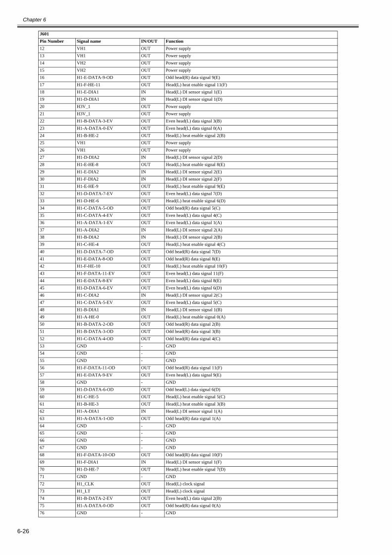
Chapter 6
6-26
12 VH1 OUT Power supply13 VH1 OUT Power supply14 VH2 OUT Power supply15 VH2 OUT Power supply16 H1-E-DATA-9-OD OUT Odd head(R) data signal 9(E)17 H1-F-HE-11 OUT Head(L) heat enable signal 11(F)18 H1-E-DIA1 IN Head(L) DI sensor signal 1(E)19 H1-D-DIA1 IN Head(L) DI sensor signal 1(D)20 H3V_1 OUT Power supply21 H3V_1 OUT Power supply22 H1-B-DATA-3-EV OUT Even head(L) data signal 3(B)23 H1-A-DATA-0-EV OUT Even head(L) data signal 0(A)24 H1-B-HE-2 OUT Head(L) heat enable signal 2(B)25 VH1 OUT Power supply26 VH1 OUT Power supply27 H1-D-DIA2 IN Head(L) DI sensor signal 2(D)28 H1-E-HE-8 OUT Head(L) heat enable signal 8(E)29 H1-E-DIA2 IN Head(L) DI sensor signal 2(E)30 H1-F-DIA2 IN Head(L) DI sensor signal 2(F)31 H1-E-HE-9 OUT Head(L) heat enable signal 9(E)32 H1-D-DATA-7-EV OUT Even head(L) data signal 7(D)33 H1-D-HE-6 OUT Head(L) heat enable signal 6(D)34 H1-C-DATA-5-OD OUT Odd head(R) data signal 5(C)35 H1-C-DATA-4-EV OUT Even head(L) data signal 4(C)36 H1-A-DATA-1-EV OUT Even head(L) data signal 1(A)37 H1-A-DIA2 IN Head(L) DI sensor signal 2(A)38 H1-B-DIA2 IN Head(L) DI sensor signal 2(B)39 H1-C-HE-4 OUT Head(L) heat enable signal 4(C)40 H1-D-DATA-7-OD OUT Odd head(R) data signal 7(D)41 H1-E-DATA-8-OD OUT Odd head(R) data signal 8(E)42 H1-F-HE-10 OUT Head(L) heat enable signal 10(F)43 H1-F-DATA-11-EV OUT Even head(L) data signal 11(F)44 H1-E-DATA-8-EV OUT Even head(L) data signal 8(E)45 H1-D-DATA-6-EV OUT Even head(L) data signal 6(D)46 H1-C-DIA2 IN Head(L) DI sensor signal 2(C)47 H1-C-DATA-5-EV OUT Even head(L) data signal 5(C)48 H1-B-DIA1 IN Head(L) DI sensor signal 1(B)49 H1-A-HE-0 OUT Head(L) heat enable signal 0(A)50 H1-B-DATA-2-OD OUT Odd head(R) data signal 2(B)51 H1-B-DATA-3-OD OUT Odd head(R) data signal 3(B)52 H1-C-DATA-4-OD OUT Odd head(R) data signal 4(C)53 GND - GND54 GND - GND55 GND - GND56 H1-F-DATA-11-OD OUT Odd head(R) data signal 11(F)57 H1-E-DATA-9-EV OUT Even head(L) data signal 9(E)58 GND - GND59 H1-D-DATA-6-OD OUT Odd head(L) data signal 6(D)60 H1-C-HE-5 OUT Head(L) heat enable signal 5(C)61 H1-B-HE-3 OUT Head(L) heat enable signal 3(B)62 H1-A-DIA1 IN Head(L) DI sensor signal 1(A)63 H1-A-DATA-1-OD OUT Odd head(R) data signal 1(A)64 GND - GND65 GND - GND66 GND - GND67 GND - GND68 H1-F-DATA-10-OD OUT Odd head(R) data signal 10(F)69 H1-F-DIA1 IN Head(L) DI sensor signal 1(F)70 H1-D-HE-7 OUT Head(L) heat enable signal 7(D)71 GND - GND72 H1_CLK OUT Head(L) clock signal73 H1_LT OUT Head(L) clock signal74 H1-B-DATA-2-EV OUT Even head(L) data signal 2(B)75 H1-A-DATA-0-OD OUT Odd head(R) data signal 0(A)76 GND - GND
J601Pin Number Signal name IN/OUT Function

Chapter 6
6-27
T-6-46
77 GND - GND78 GND - GND
J602Pin Number Signal name IN/OUT Function1 VH3 OUT Power supply2 VH3 OUT Power supply3 VH3 OUT Power supply4 VHT34 OUT Power supply5 H0-F-DATA-10-EV OUT Even head(R) data signal 10(F)6 IO_ASIC_SDA IN/OUT Head ROM control signal(data)7 IO_ASIC_SCL OUT Head ROM control signal(clock)8 VH2 OUT Power supply9 H0-C-DIA1 IN Head(R) DI sensor signal 1(C)10 H0-A-HE-1 OUT Head(R) heat enable signal 1(A)11 VH3 OUT Power supply12 VH3 OUT Power supply13 VH3 OUT Power supply14 VH4 OUT Power supply15 VH4 OUT Power supply16 H0-E-DATA-9-OD OUT Odd head(R) data signal 9(E)17 H0-F-HE-11 OUT Head(R) heat enable signal 11(F)18 H0-E-DIA1 IN Head(R) DI sensor signal 1(E)19 H0-D-DIA1 IN Head(R) DI sensor signal 1(D)20 H3V_0 OUT Power supply21 H3V_0 OUT Power supply22 H0-B-DATA-3-EV OUT Even head(R) data signal 3(B)23 H0-A-DATA-0-EV OUT Even head(R) data signal 0(A)24 H0-B-HE-2 OUT Head(R) heat enable signal 2(B)25 VH3 OUT Power supply26 VH3 OUT Power supply27 H0-D-DIA2 IN Head(R) DI sensor signal 2(D)28 H0-E-HE-8 OUT Head(R) heat enable signal 8(E)29 H0-E-DIA2 IN Head(R) DI sensor signal 2(E)30 H0-F-DIA2 IN Head(R) DI sensor signal 2(E)31 H0-E-HE-9 OUT Head(R) heat enable signal 9(E)32 H0-D-DATA-7-EV OUT Even head(R) data signal 7(D)33 H0-D-HE-6 OUT Head(R) heat enable signal 6(D)34 H0-C-DATA-5-OD OUT Odd head(R) data signal 5(C)35 H0-C-DATA-4-EV OUT Even head(R) data signal 4(C)36 H0-A-DATA-1-EV OUT Even head(R) data signal 1(A)37 H0-A-DIA2 IN Head(R) DI sensor signal 2(A)38 H0-B-DIA2 IN Head(R) DI sensor signal 2(B)39 H0-C-HE-4 OUT Head(R) heat enable signal 4(C)40 H0-D-DATA-7-OD OUT Odd head(R) data signal 7(D)41 H0-E-DATA-8-OD OUT Odd head(R) data signal 8(E)42 H0-F-HE-10 OUT Head(R) heat enable signal 10(F)43 H0-F-DATA-11-EV OUT Even head(R) data signal 11(F)44 H0-E-DATA-8-EV OUT Even head(R) data signal 8(E)45 H0-D-DATA-6-EV OUT Even head(R) data signal 6(D)46 H0-C-DIA2 IN Head(R) DI sensor signal 2(C)47 H0-C-DATA-5-EV OUT Even head(R) data signal 5(C)48 H0-B-DIA1 IN Head(R) DI sensor signal 1(B)49 H0-A-HE-0 OUT Head(R) heat enable signal 0(A)50 H0-B-DATA-2-OD OUT Odd head(R) data signal 2(B)51 H0-B-DATA-3-OD OUT Odd head(R) data signal 3(B)52 H0-C-DATA-4-OD OUT Odd head(R) data signal 4(C)53 GND - GND54 GND - GND55 GND - GND56 H0-F-DATA-11-OD OUT Odd head(R) data signal 11(F)57 H0-E-DATA-9-EV OUT Even head(R) data signal 9(E)58 GND - GND59 H0-D-DATA-6-OD OUT Odd head(R) data signal 6(D)
J601Pin Number Signal name IN/OUT Function
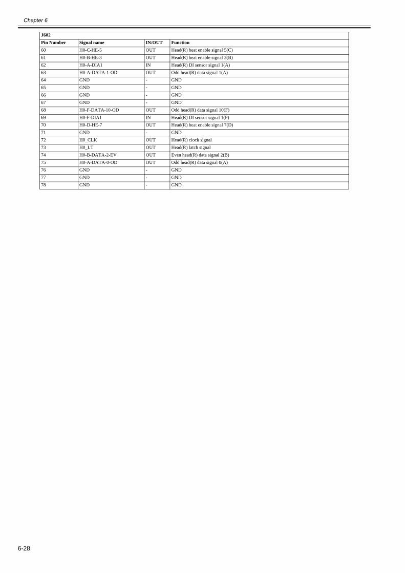
Chapter 6
6-28
60 H0-C-HE-5 OUT Head(R) heat enable signal 5(C)61 H0-B-HE-3 OUT Head(R) heat enable signal 3(B)62 H0-A-DIA1 IN Head(R) DI sensor signal 1(A)63 H0-A-DATA-1-OD OUT Odd head(R) data signal 1(A)64 GND - GND65 GND - GND66 GND - GND67 GND - GND68 H0-F-DATA-10-OD OUT Odd head(R) data signal 10(F)69 H0-F-DIA1 IN Head(R) DI sensor signal 1(F)70 H0-D-HE-7 OUT Head(R) heat enable signal 7(D)71 GND - GND72 H0_CLK OUT Head(R) clock signal73 H0_LT OUT Head(R) latch signal74 H0-B-DATA-2-EV OUT Even head(R) data signal 2(B)75 H0-A-DATA-0-OD OUT Odd head(R) data signal 0(A)76 GND - GND77 GND - GND78 GND - GND
J602Pin Number Signal name IN/OUT Function

Chapter 6
6-29
6.3 Version Up
6.3.1 Firmware Update Tool0020-1951
Use of the following tools allows you to update the firmware of the main controller incorporated in the printer from the computer.
- imagePROGRAF Firmware Update Tool (for user)- L Printer Service Tool (for service)
1. imagePROGRAF Firmware Update ToolThe imagePROGRAF Firmware Update Tool is the tool for user.
Procedure:1) Start the imagePROGRAF Firmware Update Tool.2) Make sure that the printer is the online mode.3) Transfer the firmware data to the printer according to the instructions shown on the LCD of the operation panel.4) The message shown on the LCD of the operation panel changes and the firmware is updated automatically.5) After having updated the firmware, the computer will restart.
Connection method with the computer:USB, Network
2. L Printer Service ToolThis tool has the following functions.- The update function of the printer firmware- The display function of the printer information
Connection method with the computer:USB, Network
a) Screen description
F-6-4[1] Main menu Choose the menu to execute.[2] Main menu button Choose the menu to execute between the [Information] and the [Firmware] and the [Files].[3] Sub menu button The sub menu button is displayed according to the menu choosed by main menu or main menu button.[4] Printer information area The information of the printer connected with computer is shown according to the choosed menu.[5] Message area The message of executed menu is shown. And the message is saved as the text file when choosing the "[Service]-[Save Message]" of the main menu.
[1]
[2]
[3]
[4]
[5]

Chapter 6
6-30
b) Operation1) Showing the information of the printerThe data of PRINT INF or status print is shown.
(1) Choose the [Information] of the main menu button or the "[Service]-[Information]" of the main menu.
F-6-5(2) Choose the printer from the list shown to the printer information area.
MEMO:- The list is refreshed when choosing the [Refresh] of the sub menu button or the "[View]-[Refresh]" of the main menu.- The printer is searched according to the setting of the [Specify Search Range] dialogue box after choosing the "[View]-[Specify Search Range]" of the main menuto display the dialogue box. The five IP addresses at the maximum can register when searching by the IP address.
F-6-6
(3)-1 Choose the [Display PRINT INF] of the sub menu button or the "[Information]-[Display PRINT INF]" of the main menu when showing the PRINT INF.- The data of PRINT INF is shown by the appointed application software.
(3)-2 Choose the [Display Status Print] of the sub menu button or the "[Information]-[Display Status Print]" of the main menu when showing the Status Print.- The data of Status Print is shown by the appointed application software.

Chapter 6
6-31
MEMO:- The application software used to show the data and the folder used to store the files can change by the "[Service]-[Setup]" of the main menu.
F-6-7[1] This menu can change the folder used to store the file.[2] This menu can change the application software used to show the data.
- The printer name can add by the "[Service]-[Add Printer]" of the main menu.
F-6-8
2) Updating the firmware of the printerThe firmware of printer can update according to the following procedure.
(1) Choose the [Firmware] of the main menu button or the "[Service]-[Firmware]" of the main menu.
F-6-9(2) Choose the printer to update from the list of the printer shown to the printer information area.
[1]
[2]

Chapter 6
6-32
MEMO:- The printer list is refreshed when choosing the [Refresh] of the sub menu button or the "[View]-[Refresh]" of the main menu.- The printer is searched according to the setting of the [Specify Search Range] dialogue box after choosing the "[View]-[Specify Search Range]" of the main menuto display the dialogue box. The five IP addresses at the maximum can register when searching by the IP address.
F-6-10
(3) Choose the [Specify Firmware] of the sub menu button or the "[Firmware]-[Specify Firmware]" of the main menu.Specify the folder stored the file by the [Specify Firmware Folder] of the [Specify Firmware] dialogue box or specify the file by the [Specify Firmware File] of thedialogue box.
F-6-11(4) Make sure that the printer is the online mode or the download mode.The firmware of the printer is updated when choosing the [Transfer Firmware] of the sub menu button or the "[Firmware]-[Transfer Firmware]" of the main menu.
MEMO:The Printer becomes the force transfer mode when choosing the "[Firmware]-[Force Transfer Mode]" of the main menu. Thereby, you can choose the [TransferFirmware] without concerning the status of the printer.
3) Managing the information of the printerThe list of the PRINT INF or the status print gotten according to the procedure of "1) Showing the information of the printer" can manage.
(1) Choose the [Files] of the main menu button or the "[Service]-[Files]" of the main menu.- The list of the PRINT INF or the status print gotten so far is shown in the printer information area.
F-6-12(2) Choose the [Display] of the sub menu button or the "[Files]-[Display]" of the main menu after selecting the list that want to show in the printer information area.The multiple selection from the lists is possible.- The data of the selected PRINT INF or status print is shown.
MEMO:- The user information can set to the list after choosing the [Input User Information] of the sub menu button or the "[Files]-[Input User Information]" of the mainmenu. The input of max 511 characters is possible.- In case of deleting the list, choose the "[Files]-[Delete Files]" of main menu after selecting the list which want to delete from the printer information area.

Chapter 6
6-33
6.4 Service Tools
6.4.1 Tool List0012-6675
T-6-47
T-6-48
General-purpose tools ApplicationLong phillips scerewdriver Inserting and removing screwPhillips scerewdriver Inserting and removing screwFlat-head screwdriver Removing the E-ringNeedle-nose pliers Inserting and removing the spring partsHex key wrench Inserting and removing hexagonal screwsFlat brush Applying greaseLint free paper Wiping off inkRubber gloves Preventing ink stains
Special-purpose tools ApplicationGrease FLOIL G-5000H(FY9-6022)
Applying to specified locations
Cover Switch Tool(QY9-0103)
Pressing the cover switch


Chapter 7 SERVICE MODE


Contents
Contents
7.1 Service Mode .................................................................................................................................................................7-17.1.1 Service Mode Operation .............................................................................................................................................................. 7-17.1.2 Map of the Service Mode............................................................................................................................................................. 7-27.1.3 Details of Service Mode............................................................................................................................................................. 7-117.1.4 e-Maintenance/imageWARE Remote........................................................................................................................................ 7-287.1.5 Viewing PRINT INF.................................................................................................................................................................. 7-38
7.2 Special Mode................................................................................................................................................................7-537.2.1 Special Modes for Servicing ...................................................................................................................................................... 7-53


Chapter 7
7-1
7.1 Service Mode
7.1.1 Service Mode Operation0023-2922
a) How to enter the Service modeEnter service mode according to the following procedure:
1) Turn off the printer power. 2) Turn on the power while pressing the [Load] key and [Navigate] key. * Keep pressing the above keys until "Initializing" is displayed.3) "S" appears at the top right of the display.4) Press the key or key to choose the [Set./Adj. Menu] and press the [OK] key. "SERVICE MODE" appears in the menu list and the MESSAGE LED flashes.5) Press the key or key to choose "SERVICE MODE" and press the [OK] key. * Service mode is added to the [Set./Adj. Menu]. Service mode can be entered even when an error occurs (an error message is displayed) by turning off the poweronce and then pressing the above keys.
b) How to exit the Service modeTurn off the printer.
c) Key operation in the service mode- Selecting menus and paremeters: or key- Going to the next lower-level menu: key- Going to the previous higher-level menu: key- Determining a selected menu or parameter:[OK] key

Chapter 7
7-2
7.1.2 Map of the Service Mode0030-4816
The hierarchy of menus and parameters in the Service Mode is as shown below.
First Level Second Level Third Level Fourth Level Fifth Level Sixth LevelDISPLAY PRINTINF YES/NO : Select YES to print
SYSTEM S/NTYPELF TYPETMPRHSIZE LFSIZE LFSIZE CRSIZE CRAFTER INST
HEAD S/N LS/N RLOT LLOT R
INK PC---BK
WARNING 01---20
ERROR 01---20
JAM 01 1:---4:
---05 1:
---4:
INK CHECK 0 0 0 0 0 0 0 0I/O DISPLAY I/O DISPLAY 1
I/O DISPLAY 2I/O DISPLAY 3

Chapter 7
7-3
First Level Second Level Third Level Fourth Level Fifth Level Sixth LevelADJUST PRINT PATTERN NOZZLE 1 : Press the [OK] button to
executeOPTICAL AXIS : Press the [OK] button to
executeLF TUNINGLF TUNIG 2
HEAD ADJ. MANUAL HEAD ADJ EXTENSION : Press the [OK] button to execute
DETAIL : Press the [OK] button to execute
BASIC : Press the [OK] button to execute
ADJ. SETTING A A-1 : Adjustment value entry---A-96 : Adjustment value entry
---F F-1 : Adjustment value entry
F-2 : Adjustment value entrySAVE SETTINGS YES/NO
RESET SETTINGS YES/NONOZZLE CHECK POS. YES/NOGAP CALIB. YES/NOCHANGE LF TYPE 0/1ROUGH EXCUTE YES/NOAUTO REG EXCUTE YES/NOCR REG EXCUTE YES/NO
RESET YES/NOCR MOTOR COG YES/NOMARGIN ADJ TOP MARGIN ADJ -2.0 to 2.0
BTM MARGIN ADJ -2.0 to 2.0PRINT PATTERN YES/NO

Chapter 7
7-4
First Level Second Level Third Level Fourth Level Fifth LevelFUNCTION CR UNLOCK YES/NO
CR LOCK YES/NOPG CHECK YES/NOCR AUTO SCAN YES/NOCR SCAN COUNT 1 : Press the [OK] button to
set---30 : Press the [OK] button to
setCR SCAN SIZE 1 : Press the [OK] button to
set---5 : Press the [OK] button to
setCR SCAN SPEED 1 : Press the [OK] button to
set---5 : Press the [OK] button to
setOPT SENS OUTPUT YES OUTPUT0
---OUTPUT6
NONOZZLE CHK YES/NONOZZLE INF PC
---BK
MEMORY CHK DDR YES/NOEEP YES/NO
HEAD CNT CHK YES/NOREPLACE L & R PRINTHEADS YES/NO

Chapter 7
7-5
First Level Second Level Third Level Fourth Level Fifth LevelCOUNTER PRINTER LIFE TTL
LIFE ROLLLIFE CUTSHEETLIFE A---LIFE FPOWER ONW-INKCUTTERWIPESLEEP ON
CARRIAGE PRINTDRIVECR COUNTCR DIST.PRINT COUNT
PURGE CLN-A-1CLN-A-2CLN-A-3CLN-A-6CLN-A-7CLN-A-10CLN-A-11CLN-A-15CLN-A-16CLN-A-17CLN-A-TTLCLN-M-1CLN-M-4CLN-M-5CLN-M-6CLN-M-TTL
CLEAR CLR-INK CONSUMECLR-MTC EXC.CLR-HEAD L EXC.CLR-HEAD R EXC.CLR Wia-1 EXC.CLR Wia-3 EXC.CLR Wia-4 EXC.CLR Wia-5 EXC.CLR Wia-6 EXC.CLR CR-1 EXC.CLR CR-2 EXC.CLR CR-3 EXC.CLR CR-4 EXC.CLR CR-5 EXC.CLR PG-1 EXC.CLR HMa-1 EXC.CLR MT-1 EXC.CLR PL-1 EXC.CLR Mi-1 EXC.CLR MS-1 EXC.CLR-FACTORY CNT.

Chapter 7
7-6
First Level Second Level Third Level Fourth Level Fifth LevelCOUNTER EXCHANGE MTC EXC.
HEAD L EXC.HEAD R EXC.BOARD EXC.(M/B)Wia-1 EXC.Wia-3 EXC.Wia-4 EXC.Wia-5 EXC.Wia-6 EXC.CR-1 EXC.CR-2 EXC.CR-3 EXC.CR-4 EXC.CR-5 EXC.PG-1 EXC.HMa-1 EXC.MT-1 EXC.PL-1 EXC.Mi-1 EXC.MS-1 EXC.
DETAIL-CNT MOVE PRINTERN-INK CHK(PC)---N-INK CHK(BK)MEDIACONFIG-CNT

Chapter 7
7-7
First Level Second Level Third Level Fourth Level Fifth LevelCOUNTER INK-USE1 INK-USE1(PC)
---INK-USE1(BK)INK-USE1(TTL)LINK-USE1(PC)---LINK-USE1(BK)LINK-USE1(TTL)SINK-USE1(PC)---SINK-USE1(BK)SINK-USE1(TTL)N-INK-USE1(PC)---N-INK-USE1(BK)N-INK-USE1(TTL)
INK-USE2 INK-USE2(PC)---INK-USE2(BK)INK-USE2(TTL)N-INK-USE2(PC)---N-INK-USE2(BK)N-INK-USE2(TTL)
INK-EXC INK-EXC(PC)---INK-EXC(BK)INK-EXC(TTL)N-INK-EXC(PC)---N-INK-EXC(BK)N-INK-EXC(TTL)

Chapter 7
7-8
First Level Second Level Third Level Fourth Level Fifth LevelCOUNTER MEDIA 1 NAME
TTLTTLROLLROLLCUTSHEETCUTSHEET
---MEDIA 7 NAME
TTLTTLROLLROLLCUTSHEETCUTSHEET
MEDIA OTHER NAMETTLTTLROLLROLLCUTSHEETCUTSHEET
MEDIASIZE1 ROLL P-SQ 44-60P-SQ 44-60P-SQ 36-44P-SQ 36-44P-SQ 24-36P-SQ 24-36P-SQ 17-24P-SQ 17-24P-SQ -17P-SQ -17P-CNT 44-60P-CNT 36-44P-CNT 24-36P-CNT 17-24P-CNT -17
MEDIASIZE2 ROLL D-SQ 44-60D-SQ 44-60D-SQ 36-44D-SQ 36-44D-SQ 24-36D-SQ 24-36D-SQ 17-24D-SQ 17-24D-SQ -17D-SQ -17D-CNT 44-60D-CNT 36-44D-CNT 24-36D-CNT 17-24D-CNT -17

Chapter 7
7-9
First Level Second Level Third Level Fourth Level Fifth LevelCOUNTER MEDIASIZE1 CUT P-SQ 44-60
P-SQ 44-60P-SQ 36-44P-SQ 36-44P-SQ 24-36P-SQ 24-36P-SQ 17-24P-SQ 17-24P-SQ -17P-SQ -17P-CNT 44-60P-CNT 36-44P-CNT 24-36P-CNT 17-24P-CNT -17
MEDIASIZE2 CUT D-SQ 44-60D-SQ 44-60D-SQ 36-44D-SQ 36-44D-SQ 24-36D-SQ 24-36D-SQ 17-24D-SQ 17-24D-SQ -17D-SQ -17D-CNT 44-60D-CNT 36-44D-CNT 24-36D-CNT 17-24D-CNT -17
HEAD DOT CNT. 1 PC1---BKTTL
HEAD DOT CNT. 2 PC1---BKTTL
PARTS CNT. COUNTER Wia-1 OK/W1/W2/E1:002:003:004:00
---COUNTER MS-1 OK/W1/W2/E
1:002:003:004:00
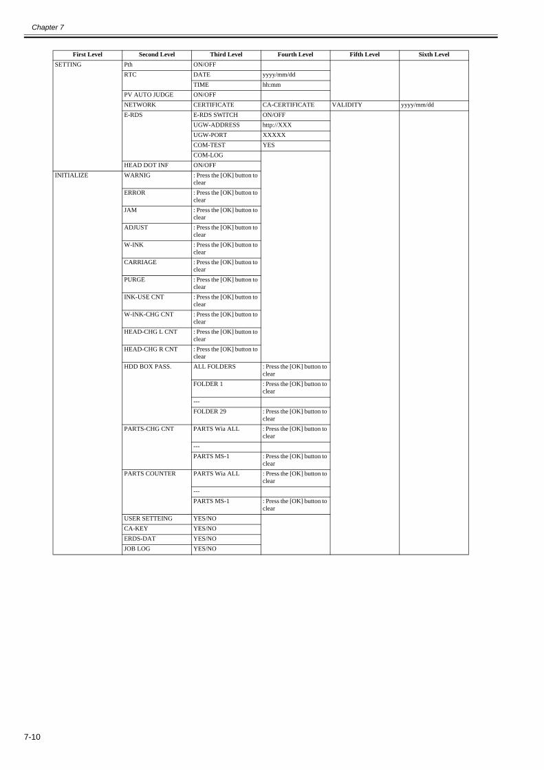
Chapter 7
7-10
First Level Second Level Third Level Fourth Level Fifth Level Sixth LevelSETTING Pth ON/OFF
RTC DATE yyyy/mm/ddTIME hh:mm
PV AUTO JUDGE ON/OFFNETWORK CERTIFICATE CA-CERTIFICATE VALIDITY yyyy/mm/ddE-RDS E-RDS SWITCH ON/OFF
UGW-ADDRESS http://XXXUGW-PORT XXXXXCOM-TEST YESCOM-LOG
HEAD DOT INF ON/OFFINITIALIZE WARNIG : Press the [OK] button to
clearERROR : Press the [OK] button to
clearJAM : Press the [OK] button to
clearADJUST : Press the [OK] button to
clearW-INK : Press the [OK] button to
clearCARRIAGE : Press the [OK] button to
clearPURGE : Press the [OK] button to
clearINK-USE CNT : Press the [OK] button to
clearW-INK-CHG CNT : Press the [OK] button to
clearHEAD-CHG L CNT : Press the [OK] button to
clearHEAD-CHG R CNT : Press the [OK] button to
clearHDD BOX PASS. ALL FOLDERS : Press the [OK] button to
clearFOLDER 1 : Press the [OK] button to
clear---FOLDER 29 : Press the [OK] button to
clearPARTS-CHG CNT PARTS Wia ALL : Press the [OK] button to
clear---PARTS MS-1 : Press the [OK] button to
clearPARTS COUNTER PARTS Wia ALL : Press the [OK] button to
clear---PARTS MS-1 : Press the [OK] button to
clearUSER SETTEING YES/NOCA-KEY YES/NOERDS-DAT YES/NOJOB LOG YES/NO

Chapter 7
7-11
7.1.3 Details of Service Mode0030-4817
This section provides details of the Service mode menu.
a) DISPLAYDisplays and prints the printer information.
1) PRINF INFPrints adjustment values in the User menu, [DISPLAY] and [COUNTER] parameters on A4-size or lager paper.When roll media is used, the layout is optimized according to the media width.
2) SYSTEMDisplays the printer information shown below.
3) HEADDisplays the following EEPROM information of the printhead.
4) INKDisplays the numbers of days passed since installation of the following ink tanks.
5) WARNINGDisplays the warning history (up to 20 events). The newest event has the smallest history number.
6) ERRORDisplays the error history (up to 20 events). The newest event has the smallest history number.
7) JAMDisplays log of jams that have occurred (up to five events). The newest event has the smallest history number.
Indicates the date and time of jam and error code. "0000" is displayed if there is no log.
F-7-1
Press the key to display detail information.Press the key or key to navigate among detail information display 1 to 4.Detail information display 1
F-7-2
Display Description UnitS/N Serial number of printer -TYPE Type setting on main controller PCB
* iPF8400S/8410S are represented by 44".-
LF TYPE Feed roller type: 0 or 1 -TMP Ambient temperature centigrade
degreesRH Ambient humidity %SIZE LF Detected size of loaded media (feed direction)
0 is always detected for the roll media.mm/inch
SIZE CR Detected size of loaded media (carriage scan direction) mm/inchAFTER INST.
Number of days since initial installation Days
Display Description
S/N R Serial number of printhead R
S/N L Serial number of printhead L
LOT R Lot number of printhead R
LOT L Lot number of printhead L
Display Description Unit
BK Number of days passed since the BK ink tank was installed Day(s)MBK Number of days passed since the MBK ink tank was installed Day(s)C Number of days passed since the C ink tank was installed Day(s)M Number of days passed since the M ink tank was installed Day(s)Y Number of days passed since the Y ink tank was installed Day(s)PC Number of days passed since the PC ink tank was installed Day(s)PM Number of days passed since the PM ink tank was installed Day(s)GY Number of days passed since the GY ink tank was installed Day(s)
X X X X - X X X X
0 1 M M / D D H H : M M
1 : X X X X X X X X X
J A M 0 1
1 2 3 4 5 6 7 8 9
X
10

Chapter 7
7-12
Detail information display 2
F-7-3Detail information display 3
F-7-4Detail information display 4
F-7-5
8) INK CHECKDisplays the number of times the remaining ink level detection function was turned off, to accommodate refilled ink cartridges in the order of PC, C, BK, MBK,Y, M, PM and GY.0: Never1: Executed at least once
Display Description LCD display contents1 Jam type 1:Carriage error, 2:Jam, 3:Feed failure (delay), 4:Cut failure, *:Unknown2 Media 1:Roll media, 2:Cut sheet (manual feed from top), 3:Cut sheet (manual feed from front), 4:Cassette, *:Unknown3 Jam timing 1:Feed, 2:Print, 3:Eject, *:Unknown4 Media width detection 1:ON, 2:OFF, *:Unknown5 Head height 0:SL (1.2mm), 1:L (1.4mm), 2:M1 (1.8mm), 3:M2 (2.0mm), 4:M3 (2.2mm), 5:H (2.6mm), *:Unknown6 (Not Used) -7 Cut mode setting 1:User cut, 2:Eject cut, 3:Auto cut, *:Unknown8 Environment Display Media Information Tool's environment settings A to F according to Temperature/Humidity Detection Sensor
0: A, 1:B, 2:C, 3:D, 4:E, 5:F, *:Unknown9 Borderless printing setting 1:Bordered printing, 2:Borderless printing, *:Unknown10 (Not Used) -11 Print mode Display print mode, *:Unknown12 Media width Display media width, *:Unknown13 Media name Display media name, *:Unknown
2 : X X X X X X X X X
J A M 0 1
11
3 : X X X X
J A M 0 1
12
4 :
J A M 0 1
13
X X X X X X X X

Chapter 7
7-13
b) I/O DISPLAYThe status of each sensor and switch is shown in the display.
Sensor and switch status is shown in the display.ON = 1OFF or not used = 0
Screen 1
F-7-6
Screen 2
F-7-7
Screen 3
F-7-8
I / O D I S P L A Y 1
0 0 0 0 0 0 0 0 0 0 0 0 0 0 0 0
1 2 3 4 5 6 7 8 9 10 11 12 13 14 15 16
(Upper row)
(Lower row)
(Display position)
I / O D I S P L A Y 2
0 0 0 0 0 0 0 0 0 0 0 0 0 0 0 0
17 18 19 20 21 22 23 24 25 26 27 28 29 30 31 32
(Upper row)
(Lower row)
(Display position)
I / O D I S P L A Y 3
0 0 0 0 0 0 0 0 0 0 0 0 0 0 0 0
33 34 35 36 37 38 39 40 41 42 43 44 45 46 47 48
(Upper row)
(Lower row)
(Display position)

Chapter 7
7-14
Screen 1, Screen 2 and Screen 3 are selectable with the and keys.These screens display the associated sensor status as listed in the table below.
Display position Sensor name LCD display contents
1 Pump Cam Sensor 0: Sensor ON, 1: Sensor OFF2 Valve open/closed detection sensor (R) 0: Sensor ON, 1: Sensor OFF3 Agitation cam sensor (L) 0: Sensor ON, 1: Sensor OFF4 Agitation cam sensor (R) 0: Sensor ON, 1: Sensor OFF5 (Not Used) -6 Lift cam sensor 0: Sensor ON, 1: Sensor OFF7 Feed roller HP sensor 0: Sensor ON, 1: Sensor OFF8 Upper cover lock switch 0: Cover open, 1: Cover close9 Carriage cover sensor 0: Cover open, 1: Cover close10 Ink tank cover switch (R) 0: Cover open, 1: Cover close11 Ink tank cover switch (L) 0: Cover open, 1: Cover close12 (Not Used) -13 (Not Used) -14 (Not Used) -15 (Not Used) -16 (Not Used) -17 (Not Used) -18 (Not Used) -19 (Not Used) -20 (Not Used) -21 (Not Used) -22 Carriage HP sensor 0: Sensor ON, 1: Sensor OFF23 Pressure release switch 0: Realeased, 1:Pressured24 Media sensor 0: No media, 1: Media loaded25 (Not Used) -26 (Not Used) -27 (Not Used) -28 Media take-up unit detection 0: Undetected, 1: Detected29 Media take-up sensor input signal 0: LO, 1: HI30 Valve open/closed detection sensor (L) 0: Sensor ON, 1: Sensor OFF31 (Not Used) -32 (Not Used) -33 (Not Used) -34 (Not Used) -35 (Not Used) -36 (Not Used) -37 (Not Used) -38 (Not Used) -39 (Not Used) -40 (Not Used) -41 (Not Used) -42 (Not Used) -43 (Not Used) -44 (Not Used) -45 Flexible cable connection detection
(J3501, J3502, J3601, J3602)0: Connection, 1: Disconnection
46 (Not Used) -47 (Not Used) -48 (Not Used) -

Chapter 7
7-15
c) ADJUSTPerforms adjustments and prints the adjustment and check patterns necessary for adjusting the printer parts.
1) PRINT PATTERN
2) HEAD ADJ.Set or initialize the registration adjustment values of each printheads.
3) NOZZLE CHECK POS.This mode is for adjusting the optical axis of the head management sensor. For details, refer to "Disassembly/Reassembly" > "Adjustment and Setup Items" > "Pro-cedure after replacing the head management sensor".
4) GAP CLIB.This mode measures the gap between the printhead and media by using the multi sensor and corrects the calibration value.
5) CHANGE LF TYPEChange the type of the feed roller.0: Old feed roller1: New feed roller
Display DescriptionNOZZLE 1 Prints the nozzle check pattern by single direction/ single pass without using the non-discharging
back up.It is used to check for the non-discharging nozzles.- Media size: A4- Media type: any
OPTICAL AXIS Prints the pattern and adjusts the optical axis of the multi sensor.For details, refer to "Disassembly/Reassembly" > "Adjustment and Setup Items" > "Procedure after replacing the carriage unit or multi sensor".- Media type: photo glossy paper
LF TUNING Carry out automatic correction of eccentricity of the feed roller. For more details, refer to "Disassembly/Reassembly" > "Adjustment and Setup Items" > "Procedure after replacing the feed roller and reed roller encoder".- The media type is "gloss photo paper".
LF TUNING 2 Carry out manual correction of eccentricity of the feed roller. For more details, refer to "Disassembly/Reassembly" > "Adjustment and Setup Items" > "Procedure after replacing the feed roller and reed roller encoder".- The media type is "gloss photo paper".
Display DescriptionMANUAL HEAD ADJ EXTENSION Prints the detail patterns for the manual head adjustment at CR SCAN SPEED 2 (25inch/sec [high printing
mode]).After printing, the mode will change to [ADJ. SETTING]. Check the printed patterns and input the set values.Try adjustment in this mode if vertical lines are warped or colors are out of alignment when the printer driver option "High-Precision Printing" or "Priority on dot placement accuracy" is selected.
DETAIL Prints the detail patterns for the manual head adjustment at CR SCAN SPEED 3 and 4 (33.3, 40inch/sec).After printing, the mode will change to [ADJ. SETTING]. Check the printed patterns and input the set values.Try adjustment in this mode if "BASIC" does not improve printing.
BASIC Prints the basic patterns for the manual head adjustment at CR SCAN SPEED 1 to 4 (12.5 to 40inch/sec).After printing, the mode will change to [ADJ. SETTING]. Check the printed patterns and input the set values.
ADJ. SETTING A to F A-1 to F-2 This mode is to input the registration adjustment values.It is possible to return the values to the former one by printing the status print before changing the value.
SAVE SETTINGS Save the registration adjustment values that has been input. RESET SETTINGS Initialize the registration adjustment values (to 0).

Chapter 7
7-16
6) ROUGHPrints the pattern for auto head adjustment and adjust it (rough adjustment).
7) AUTO REGPrints the pattern for auto head adjustment and adjust it.
8) CR REGExecutes automatic head adjustment.Make this adjustment if the resistration remains partially misregistered after user-mode head adjustment.EXECUTE: Execute automatic head adjustment.RESET: Reset the resistration adjustment value (0).
- Applicable media size is A2 (17inch) or larger.- Applicable media type is photo glossy paper.
If an error message appears when performing CR REG, check the following.Replace the multi sensor if the error reoccurs after checking and performing CR REG again.<CHECK>1. Check for non-discharging of the printhead and dirty media, and replace the printhead and/or media if necessary.2. Perform [Head Cleaning A].3. Perform [Head Posi. Adj.]-[Auto].
9) CR MOTOR COGAdjust the carriage motor rotation.Perform in the following cases:- When removing/attaching or replacing the carriage or carriage belt.- When replacing the carriage motor or linear encoder sensor.- When there is excessive load on the carriage (such as when jamming)
If the following error message appears when performing CR MOTOR COG, check that carriage and carriage belt are installed properly and clean the rail shaft. Ifthe error still occurs, replace the carriage motor.
F-7-9
10) MARGIN ADJThis mode is to perform the fine adjustment of the leading and trailing edge margin.
Display DescriptionTOP MARGIN ADJ Set the fine adjustment value of leading edge margin.
Range: -2.0 to 2.0mm (in 0.1mm increments)BTM MARGIN ADJ Set the fine adjustment value of trailing edge margin.
Range: -2.0 to 2.0mm (in 0.1mm increments)PRINT PATTERN Print the pattern for checking the margin.
After adjusting the margin, make sure of the margin by printing the pattern.
E R R O R
C R V I B R A T I O N

Chapter 7
7-17
d) FUNCTION
1) CR UNLOCKUnlocks the carriage.When CR UNLOCK is performed, the carriage lock pin is lowered and the carriage can be moved.
2) CR LOCKLocks the carriage.When CR LOCK is performed, the carriage lock pin is raised and the carriage is locked.
3) PG CHECKInitializes the purge unit.
4) CR AUTO SCANThe carriage scans.When CR AUTO SCAN is performed, the carriage scans with the count, width, and speed set with CR SCAN COUNT/CR SCAN SIZE/CR SCAN SPEED.
5) CR SCAN COUNTSets the number of scans (1 to 30) to be performed with CR AUTO SCAN. Default:1
6) CR SCAN SIZESets the scan width to be performed with CR AUTO SCAN.1:A4, 2:17inch, 3:24inch, 4:36inch, 5:44inchDefault:5
7) CR SCAN SPEEDSets the speed of the scan to be performed with CR AUTO SCAN.1:12.5, 2:25.0, 3:33.3, 4:40.0 (Unit: inch/sec)Default:1
MEMO:The settings made with CR SCAN COUNT, CR SCAN SIZE, CR SCAN SPEED are reset to default when the power is reset.
8) OPT SENS OUTPUTDisplays the values (analog value) multi sensor detected from the media. You can confirm the amount of margin the media has with the values read with the multi sensor and the status of the multi sensor by comparing the values with thethreshold.
Press the key or key to navigate among OUTPUT 0 to 6 windows.OUTPUT 0
F-7-10OUTPUT 1
F-7-11OUTPUT 2
F-7-12OUTPUT 3
F-7-13OUTPUT 4
F-7-14
X X X X X X X X X X X X X X X
O U T P U T 0
1 1 1 2 2 2 3 3 3 4 4 4 5 5 5
X X X X X X X X X X X X X X X
O U T P U T 1
6 6 6 7 7 7 8 8 8 9 9 9 10 10 10
X X X X X X X X X X X X X X X
O U T P U T 2
11 11 11 12 12 12 13 13 13 14 14 14 15 15 15
X X X X X X X X X X X X X X X
O U T P U T 3
16 16 16 17 17 17 18 18 18 19 19 19 20 20 20
X X X X X X X X X X X X X X X
O U T P U T 4
21 21 21 22 22 22 23 23 23 24 24 24 25 25 25

Chapter 7
7-18
OUTPUT 5
F-7-15OUTPUT 6
F-7-16
MEMO:- Displays all "?" if "GAP CALIB" is not performed.- If the value exceeds 1000, 999 is displayed.
Display position Description
1 Media edge (diffuse reflection) media output (including outside light)2 Media edge (diffuse reflection) outside light output (when LED is OFF)3 Media edge (diffuse reflection) platen output (excluding outside light)4 Media edge (diffuse reflection) gain5 Media edge (diffuse reflection) current value (Unit: X10mA)6 Media edge (regular reflection) media output (including outside light)7 Media edge (regular reflection) outside light output (when LED is OFF)8 Media edge (regular reflection) platen output (excluding outside light)9 Media edge (regular reflection) gain10 Media edge (regular reflection) current value (Unit: X10mA)11 GAP_Far media output (including outside light)12 GAP_Far outside light output (when LED is OFF)13 GAP_Far platen output (excluding outside light)14 GAP_Far gain15 GAP_Far current value (Unit: X10mA)16 GAP_Near media output (including outside light)17 GAP_Near outside light output (when LED is OFF)18 GAP_Near platen output (excluding outside light)19 GAP_Near gain20 GAP_Near current value (Unit: X10mA)21 Density (red) media output (including outside light)22 Density (red) outside light output (when LED is OFF)23 Density (red) platen output (excluding outside light)24 Density (red) gain25 Density (red) current value (Unit: X10mA)26 Density (green) media output27 Density (green) outside light output (including outside light)28 Density (green) platen output (excluding outside light)29 Density (green) gain30 Density (green) current value (Unit: X10mA)31 Density (blue) media output (including outside light)32 Density (blue) outside light output (when LED is OFF)33 Density (blue) platen output (excluding outside light)34 Density (blue) gain35 Density (blue) current value (Unit: X10mA)
X X X X X X X X X X X X X X X
O U T P U T 5
26 26 26 27 27 27 28 28 28 29 29 29 30 30 30
X X X X X X X X X X X X X X X
O U T P U T 6
31 31 31 32 32 32 33 33 33 34 34 34 35 35 35

Chapter 7
7-19
1. Checking "OUTPUT 0" and "OUTPUT 1" when media (excluding clear film) is fed[Check 1]Check whether the multi sensor performance has degraded or whether the media is compatible with the multi sensor.
When "Media edge (diffuse reflection) gain" and "Media edge (diffuse reflection) current value" are maximum values and "Media edge (diffuse reflection) mediaoutput" is 186 or less, an error occurs.Maximum value of "Media edge (diffuse reflection)" gain: 255Maximum value of "Media edge (diffuse reflection)" current value: 320
When the multi sensor and media are normal, the following values are displayed:
[Check 2]Check whether the multi sensor performance has degraded or whether the media is compatible with the multi sensor.
When the difference between "Media edge (diffuse reflection) gain" and "Media edge (diffuse reflection) platen output" is 100 or less, an error occurs.When the multi sensor and media are normal, the difference is about 300-600.
[Check 3]Check the effect of external diffuse light.
When the difference between "Media edge (diffuse reflection) external light output" and "Media edge (diffuse reflection) platen output" is 500 or more, the effectof diffuse light is judged as being great.When the effect is normal, the difference is about 50-300.
[Check 4]Check whether the media is compatible.
When the result of "Media edge (regular reflection) gain"x"Media edge (regular reflection) current value" is five times as large as the result of "Media edge (diffusereflection) gain"x"Media edge (diffuse reflection) current value", the media is judged as being incompatible with the multi sensor.If the media is compatible, the result is about 0.5 to 1.5 times for plain/glossy paper; about 1-3 times for tracing paper.
[Check 5]Check whether the media is compatible.
When the result of "Media edge (diffuse reflection) gain"x"Media edge (diffuse reflection) current value" is in one of the following, the media may be incompatiblewith the multi sensor.- Nine or more times as large as that of plain paper (normally, 2000-7000)- Ten or more times as large as that of glossy paper (normally, 1600-5000)- Three or more times as large as that of tracing paper (normally, 6000-20000)
2. Checking "OUTPUT 0" when clear film is fed
[Check 1]Check whether the multi sensor performance has degraded or whether the media is compatible.
When the "Media edge (regular reflection) gain" and "Media edge (regular reflection) current value" are maximum values and "Media edge (regular reflection)media output" is 186 or less, an error occurs.Maximum value of "media edge (regular reflection)" gain: 255Maximum value of "media edge (regular reflection)" current value: 320
When the multi sensor and media are normal, the following values are displayed:
[Check 2]Check whether the multi sensor performance has degraded or whether the media is compatible.
When the difference between "Media edge (regular reflection) gain" and "Media edge (regular reflection) platen output" is 100 or less, an error occurs.When the multi sensor and media are normal, the difference is about 250-500.
[Check 3]Check the effect of external diffuse light.
When the difference between "Media edge (regular reflection) external light output" and "Media edge (regular reflection) platen output" is 500 or more, the effectof diffuse light is judged as being great.When the effect is normal, the difference is about 50-300.
3. Checking "OUTPUT 2/OUTPUT 3" and "OUTPUT 4/OUTPUT 5/OUTPUT 6"
[Check 1]Check whether the multi sensor performance has degraded or whether the media is compatible.
When "GAP gain" and "GAP current value" are maximum values and "GAP media output" is 93 or less, an error occurs.Maximum value of "GAP gain": 255Maximum value of "GAP current value": 320
When the multi sensor and media are normal, "GAP gain" is about 30-250; "GAP current value" is about 200.
Media edge (diffuse reflection) gain
Media edge (diffuse reflection) current value
Media edge (diffuse reflection) media output
Plain paper About 10-35 About 200 About 500-600Glossy paper About 8-25Tracing paper About 30-100
Media edge (regular reflection) gain
Media edge (regular reflection) current value
Media edge (regular reflection) media output
Clear film About 10-60 About 200 About 500-600

Chapter 7
7-20
[Check 2]Check whether the multi sensor performance has degraded or whether the media is compatible.
When "Density gain" and "Density current value" are maximum values and "Density media output" is 168 or less, an error occurs. Maximum value of "Density gain": 255Maximum value of "Density current value": 245
When the multi sensor performance and media are normal, "Density gain" is about 5-100; "Density current value" is about 200.
9) NOZZLE CHKChecks for non-discharging nozzle with head management sensor.
10) NOZZLE INFDisplays the result of non-discharging nozzle check performed with "NOZZLE CHECK" by nozzle row of each ink color.- Press the key or key to switch the ink color.- AE:A-EVEN row, AO:A-ODD row, BE:B-EVEN row, BO:B-ODD row
F-7-1711) MEMORY CHK
12) HEAD CNT CHKConfirms the contact status of the printhead.
e) REPLACE1) L&R PRINTHEADSReplaces printheads L and R.
f) COUNTERDisplays the life (operation frequency and time) of each unit, print counts for each media type, and else.The count values can be printed from [PRINT INF].
1) PRINTER: Counters related to product life
2) CARRIAGE: Counters related to carriage unit
Display DescriptionDDR Checks the DDR-SDRAM mounted on the Main Controller PCB.EEP Checks the EEPROM.
Display Description UnitLIFE TTL Cumulative number of printed media (equivalent of A4) sheetsLIFE ROLL Cumulative number of printed roll media (equivalent of A4) sheetsLIFE CUTSHEET Cumulative number of printed cut sheets (equivalent to A4) sheetsLIFE A-F Cumulative number of printed media for environments A to F sheetsPOWER ON Cumulative power-on time (excluding the sleep time) HoursW-INK Remaining capacity of the maintenance cartridge %CUTTER Number of cutting operations (count as 1 by moving back and
forth)Times
WIPE Number of wiping operations TimesSLEEP ON Cumulative sleep-on time Hours
Display Description UnitPRINT Cumulative printing time HoursDRIVE Cumulative carriage moving time HoursCR COUNT Cumulative carriage scan count (count as 1 by moving back and forth) TimesCR DIST. Cumulative carriage scan distance (count as 1 by moving 210mm) TimesPRINT COUNT Cumulative print end count (count as 1 by capping) Times
B E : O K B O : O K
C A E : O K A O : O K

Chapter 7
7-21
3) PURGE: Counters related to purge unit
4) CLEAR: Counters related to counter initialization
Display Description UnitCLN-A-1 Cumulative number of automatic cleaning 1 (normal suction) operations TimesCLN-A-2 Cumulative number of automatic cleaning 2 (ink level adjusting) operations TimesCLN-A-3 Cumulative number of automatic cleaning 3 (initial filling) operations TimesCLN-A-6 Cumulative number of automatic cleaning 6 (strong normal suction) operations TimesCLN-A-7 Cumulative number of automatic cleaning 7 (aging) operationsCLN-A-10 Cumulative number of automatic cleaning 10 (ink filling after secondary transportation) operations TimesCLN-A-11 Cumulative number of automatic cleaning 11 (ink filling after head replacement) operations TimesCLN-A-15 Cumulative number of automatic cleaning 15 (dot count small suction) operations TimesCLN-A-16 Cumulative number of automatic cleaning 16 (sedimented ink agitation) operations TimesCLN-A-17 Cumulative number of automatic cleaning 17 (small suction) operations TimesCLN-A-TTL Total number of automatic cleaning operations TimesCLN-M-1 Cumulative number of manual cleaning 1 (normal suction) operations TimesCLN-M-4 Cumulative number of manual cleaning 4 (ink draining from head after head replacement) operations TimesCLN-M-5 Cumulative number of manual cleaning 5 (ink draining from head and tube before transportation ) operations TimesCLN-M-6 Cumulative number of manual cleaning 6 (normal strong suction) operations TimesCLN-M-TTL Total number of manual cleaning operations Times
Display Description Unit RemarksCLR-INK CONSUME Cumulative count of ink section consumption amount clearing TimesCLR-MTC EXC. Cumulative count of maintenance cartridge replacement count clearing TimesCLR-HEAD L EXC. Cumulative count of printhead L replacement count clearing TimesCLR-HEAD R EXC. Cumulative count of printhead R replacement count clearing TimesCLR Wia-1 EXC. Cumulative count of unit Wia-1 (waste ink box unit) replacement count
clearingTimes
CLR Wia-3 EXC. Cumulative count of unit Wia-3 (platen ink box unit) replacement count clearing
Times
CLR Wia-4 EXC. Cumulative count of unit Wia-4 (platen ink box unit) replacement count clearing
Times
CLR Wia-5 EXC. Cumulative count of unit Wia-5 (platen ink box unit) replacement count clearing
Times
CLR Wia-6 EXC. Cumulative count of unit Wia-6 (suction fan unit) replacement count clearing TimesCLR CR-1 EXC. Cumulative count of unit CR-1 (carriage unit bushing) replacement count
clearingTimes
CLR CR-2 EXC. Cumulative count of unit CR-2 (linear encoder sensor/linear scale/shaft cleaner) replacement count clearing
Times
CLR CR-3 EXC. Cumulative count of unit CR-3 (carriage height changing cam) replacement count clearing
Times
CLR CR-4 EXC. Cumulative count of unit CR-4 (ink tube unit/flexible cable unit) replacement count clearing
Times
CLR CR-5 EXC. Cumulative count of unit CR-5 (multi sensor) replacement count clearing TimesCLR PG-1 EXC. Cumulative count of unit PG-1 (purge unit) replacement count clearing TimesCLR HMa-1 EXC. Cumulative count of unit HMa-1 (head management sensor) replacement count
clearingTimes
CLR MT-1 EXC. Cumulative count of unit MT-1 (carriage motor) replacement count clearing TimesCLR PL-1 EXC. Cumulative count of unit PL-1 (feed motor) replacement count clearing TimesCLR Mi-1 EXC. Cumulative count of unit Mi-1 (mist fan) replacement count clearing TimesCLR MS-1 EXC. Cumulative count of unit MS-1 (multi sensor) replacement count clearing Times Calibration error index, This counter
synchronizes with CLR CR-5 EXC.CLR-FACTORY CNT. For factory Times

Chapter 7
7-22
5) EXCHANGE: Counters related to parts replacement
6) DETAIL-CNT: Other counters
7) INK-USE1: Counters related to ink consumption
8) INK-USE2: Counters related to ink consumption
Display Description UnitMTC EXC. Maintenance cartridge replacement count TimesHEAD L EXC. Printhead L replacement count TimesHEAD R EXC. Printhead R replacement count TimesBOARD EXC.(M/B) Main controller PCB replacement count TimesWia-1 EXC. Wia-1 (waste ink box unit) replacement count
(Count of executing [INITIALIZE] > [PARTS COUNTER] > [PARTS Wia-1])Times
Wia-3 EXC. Wia-3 (platen ink box unit) replacement count(Count of executing [INITIALIZE] > [PARTS COUNTER] > [PARTS Wia-3])
Times
Wia-4 EXC. Wia-4 (platen ink box unit) replacement count(Count of executing [INITIALIZE] > [PARTS COUNTER] > [PARTS Wia-4])
Times
Wia-5 EXC. Wia-5 (platen ink box unit) replacement count(Count of executing [INITIALIZE] > [PARTS COUNTER] > [PARTS Wia-5])
Times
Wia-6 EXC. Wia-6 (suction fan unit) replacement count(Count of executing [INITIALIZE] > [PARTS COUNTER] > [PARTS Wia-6])
Times
CR-1 EXC. CR-1 (carriage unit bushing) replacement count(Count of executing [INITIALIZE] > [PARTS COUNTER] > [PARTS CR-1])
Times
CR-2 EXC. CR-2 (linear encoder sensor/linear scale/shaft cleaner) replacement count(Count of executing [INITIALIZE] > [PARTS COUNTER] > [PARTS CR-2])
Times
CR-3 EXC. CR-3 (carriage height changing cam) replacement count(Count of executing [INITIALIZE] > [PARTS COUNTER] > [PARTS CR-3])
Times
CR-4 EXC. CR-4 (ink tube unit/flexible cable unit) replacement count(Count of executing [INITIALIZE] > [PARTS COUNTER] > [PARTS CR-4])
Times
CR-5 EXC. CR-5 (multi sensor) replacement count(Count of executing [INITIALIZE] > [PARTS COUNTER] > [PARTS CR-5])
Times
PG-1 EXC. PG-1 (purge unit) replacement count(Count of executing [INITIALIZE] > [PARTS COUNTER] > [PARTS PG-1])
Times
HMa-1 EXC. HMa-1 (head management sensor) replacement count(Count of executing [INITIALIZE] > [PARTS COUNTER] > [PARTS HMa-1])
Times
MT-1 EXC. MT-1 (carriage motor) replacement count(Count of executing [INITIALIZE] > [PARTS COUNTER] > [PARTS MT-1])
Times
PL-1 EXC. PL-1 (feed motor) replacement count(Count of executing [INITIALIZE] > [PARTS COUNTER] > [PARTS PL-1])
Times
Mi-1 EXC. Mi-1 (mist fan) replacement count(Count of executing [INITIALIZE] > [PARTS COUNTER] > [PARTS Mi-1])
Times
MS-1 EXC. MS-1 (multi sensor) replacement count(Count of executing [INITIALIZE] > [PARTS COUNTER] > [PARTS MS-1])
Times
Display Description UnitMOVE PRINTER Number of times "Prep.MovePrinter" on Main menu is executed. TimesN-INKCHK(XX) XX: Ink color
Count of turning off the ink remaining level detection for each colorTimes
MEDIACONFIG-CNT Count of media registered by media editor Times
Display Description UnitINK-USE1(XX) XX: Ink color
Cumulative consumption amount of generic ink ml
INK-USE1(TTL) Total amount of cumulative consumption of generic ink mlLINK-USE1(XX) XX: Ink color
Cumulative consumption amount of generic large ink ml
LINK-USE1(TTL) Total amount of cumulative consumption of generic large ink mlSINK-USE1(XX) XX: Ink color
Cumulative consumption amount of generic small ink ml
SINK-USE1(TTL) Total amount of cumulative consumption of generic small ink mlN-INK-USE1(XX) XX: Ink color
Cumulative consumption amount of refilled inkml
N-INK-USE1(TTL) Total amount of cumulative consumption of refilled ink ml
Display Description UnitINK-USE2(XX) XX: Ink color
Consumption amount of generic ink of the currently installed ink tank.ml
INK-USE2(TTL) Total consumption amount of generic ink of the currently installed ink tanks mlN-INK-USE2(XX) XX: Ink color
Consumption amount of refilled ink of the currently installed ink tankml
N-INK-USE2(TTL) Total consumption amount of refilled ink of the currently installed ink tanks ml

Chapter 7
7-23
9) INK-EXC: Counters related to ink tank replacement
10) MEDIA x (x: 1 to 7): Counters related to mediaOne to seven media types are displayed individually in order with large cumulative print area.
11) MEDIA OTHER: Counters related to mediaDisplays the total amount of cumulative print area of the other media type than the above-mentioned.
12) MEDIASIZE1 ROLL: Counters related to roll media printing
13) MEDIASIZE2 ROLL: Counters related to roll media printing
Display Description UnitINK-EXC(XX) XX: Ink color
Cumulative count of generic ink tank replacementml
INK-EXC(TTL) Total amount of cumulative count of generic ink tank replacement mlN-INK-EXC(XX) XX: Ink color
Cumulative count of refilled ink tank replacementml
N-INK-EXC(TTL) Total amount of cumulative count of refilled ink tank replacement ml
Display Description UnitNAME Media type -TTL Total amount of cumulative print area of roll media and cut sheet (metric) Sq.mTTL Total amount of cumulative print area of roll media and cut sheet (inch) Sq.fROLL Cumulative print area of roll media (metric) Sq.mROLL Cumulative print area of roll media (inch) Sq.fCUT SHEET Cumulative print area of cut sheet (metric) Sq.mCUT SHEET Cumulative print area of cut sheet (inch) Sq.f
Display Description UnitNAME Media type -TTL Total amount of cumulative print area of roll media and cut sheet (metric) Sq.mTTL Total amount of cumulative print area of roll media and cut sheet (inch) Sq.fROLL Cumulative print area of roll media (metric) Sq.mROLL Cumulative print area of roll media (inch) Sq.fCUT SHEET Cumulative print area of cut sheet (metric) Sq.mCUT SHEET Cumulative print area of cut sheet (inch) Sq.f
Display Description UnitP-SQ 44-60 Cumulative print area of paper equal to or larger than 44 inches but less than 60 inches (physical size) m2/Sq.fP-SQ 36-44 Cumulative print area of paper equal to or larger than 36 inches but less than 44 inches (physical size) m2/Sq.fP-SQ 24-36 Cumulative print area of paper equal to or larger than 24 inches but less than 36 inches (physical size) m2/Sq.fP-SQ 17-24 Cumulative print area of paper equal to or larger than 17 inches but less than 24 inches (physical size) m2/Sq.fP-SQ -17 Cumulative print area of paper less than 17 inches (physical size) m2/Sq.fP-CNT 44-60 Cumulative number of sheets of A4-equivalent paper equal to or larger than 44 inches but less than 60 inches
(physical size)sheets
P-CNT 36-44 Cumulative number of sheets of A4-equivalent paper equal to or larger than 36 inches but less than 44 inches (physical size)
sheets
P-CNT 24-36 Cumulative number of sheets of A4-equivalent paper equal to or larger than 24 inches but less than 36 inches (physical size)
sheets
P-CNT 17-24 Cumulative number of sheets of A4-equivalent paper equal to or larger than 17 inches but less than 24 inches (physical size)
sheets
P-CNT -17 Cumulative number of sheets of A4-equivalent paper less than 17 inches (physical size) sheets
Display Description UnitD-SQ 44-60 Cumulative print area of paper equal to or larger than 44 inches but less than 60 inches (data size) m2/Sq.fD-SQ 36-44 Cumulative print area of paper equal to or larger than 36 inches but less than 44 inches (data size) m2/Sq.fD-SQ 24-36 Cumulative print area of paper equal to or larger than 24 inches but less than 36 inches (data size) m2/Sq.fD-SQ 17-24 Cumulative print area of paper equal to or larger than 17 inches but less than 24 inches (data size) m2/Sq.fD-SQ -17 Cumulative print area of paper less than 17 inches (data size) m2/Sq.fD-CNT 44-60 Cumulative number of sheets of A4-equivalent paper equal to or larger than 44 inches but less than 60 inches
(data size)sheets
D-CNT 36-44 Cumulative number of sheets of A4-equivalent paper equal to or larger than 36 inches but less than 44 inches (data size)
sheets
D-CNT 24-36 Cumulative number of sheets of A4-equivalent paper equal to or larger than 24 inches but less than 36 inches (data size)
sheets
D-CNT 17-24 Cumulative number of sheets of A4-equivalent paper equal to or larger than 17 inches but less than 24 inches (data size)
sheets
D-CNT -17 Cumulative number of sheets of A4-equivalent paper less than 17 inches (data size) sheets

Chapter 7
7-24
14) MEDIASIZE1 CUT: Counters related to cut sheet printing
15) MEDIASIZE2 CUT: Counters related to cut sheet printing
16) HEAD DOT CNT.1: Counter related to dot count
17) HEAD DOT CNT.2: Counter related to dot count
Display Description UnitP-SQ 44-60 Cumulative print area of paper equal to or larger than 44 inches but less than 60 inches (physical size) m2/Sq.fP-SQ 36-44 Cumulative print area of paper equal to or larger than 36 inches but less than 44 inches (physical size) m2/Sq.fP-SQ 24-36 Cumulative print area of paper equal to or larger than 24 inches but less than 36 inches (physical size) m2/Sq.fP-SQ 17-24 Cumulative print area of paper equal to or larger than 17 inches but less than 24 inches (physical size) m2/Sq.fP-SQ -17 Cumulative print area of paper less than 17 inches (physical size) m2/Sq.fP-CNT 44-60 Cumulative number of sheets of A4-equivalent paper equal to or larger than 44 inches but less than 60 inches
(physical size)sheets
P-CNT 36-44 Cumulative number of sheets of A4-equivalent paper equal to or larger than 36 inches but less than 44 inches (physical size)
sheets
P-CNT 24-36 Cumulative number of sheets of A4-equivalent paper equal to or larger than 24 inches but less than 36 inches (physical size)
sheets
P-CNT 17-24 Cumulative number of sheets of A4-equivalent paper equal to or larger than 17 inches but less than 24 inches (physical size)
sheets
P-CNT -17 Cumulative number of sheets of A4-equivalent paper less than 17 inches (physical size) sheets
Display Description UnitD-SQ 44-60 Cumulative print area of paper equal to or larger than 44 inches but less than 60 inches (data size) m2/Sq.fD-SQ 36-44 Cumulative print area of paper equal to or larger than 36 inches but less than 44 inches (data size) m2/Sq.fD-SQ 24-36 Cumulative print area of paper equal to or larger than 24 inches but less than 36 inches (data size) m2/Sq.fD-SQ 17-24 Cumulative print area of paper equal to or larger than 17 inches but less than 24 inches (data size) m2/Sq.fD-SQ -17 Cumulative print area of paper less than 17 inches (data size) m2/Sq.fD-CNT 44-60 Cumulative number of sheets of A4-equivalent paper equal to or larger than 44 inches but less than 60 inches
(data size)sheets
D-CNT 36-44 Cumulative number of sheets of A4-equivalent paper equal to or larger than 36 inches but less than 44 inches (data size)
sheets
D-CNT 24-36 Cumulative number of sheets of A4-equivalent paper equal to or larger than 24 inches but less than 36 inches (data size)
sheets
D-CNT 17-24 Cumulative number of sheets of A4-equivalent paper equal to or larger than 17 inches but less than 24 inches (data size)
sheets
D-CNT -17 Cumulative number of sheets of A4-equivalent paper less than 17 inches (data size) sheets
Display Description UnitXX XX: Ink color
Dot counts of each colors of the currently installed printhead (x 1,000,000) dots
TTL Total dot counts of each colors of the currently installed printhead (x 1,000,000) dots
Display Description UnitXX XX: Ink color
Cumulative dot counts of each colors(x 1,000,000) dots
TTL Total cumulative dot counts of each colors (x 1,000,000) dots

Chapter 7
7-25
18) PARTS CNT. : Counter related to consumable parts
F-7-18
The displays are selectable with the and keys.Counter of the consumable part (current)
F-7-19Life of the consumable part
F-7-20Use rate until part replacement
F-7-21Counter of the consumable part (accumulate)
F-7-22
Display Description UnitCOUNTER xx-x
xx-x: Unit number of consumable parts(For detail, refer to "Maintenance and Inspection" > "Consumable Parts")
Display the status (aa) and the days passed since the counter (bbbb) resetting.- Status OK: Use rate (until part replacement) of all consumable parts included in each unit are below 90%. W1: Use rate (until part replacement) of either of the consumable parts included in each unit has reached 90% or more. W2: Use rate (until part replacement) of either of the consumable parts included in each unit has reached 100%, but no need to stop the printer. E : Use rate (until part replacement) of either of the consumable parts included in each unit has reached 100%, and the printer needs to be stopped.
Days
1: Unit number of consumable partsCounter of the consumable part (current)
2: Life of the consumable part3: Use rate until part replacement %4: Counter of the consumable part (accumulate)
a a b b b b b
C O U N T E R C R - 1
1 : x x x x x
C O U N T E R C R - 1
2 : x x x x x
C O U N T E R C R - 1
3 : x x x %
C O U N T E R C R - 1
4 : x x x x x
C O U N T E R C R - 1

Chapter 7
7-26
g) SETTINGMake various settings.
1) PthTurn on or off the head pulse rank control function.Default: OFF
2) RTCSet RTC (real time clock) after replacing the lithium battery on the main controller PCB.
3) PV AUTO JUDGESets ink saver mode.Default: OFF
4) NETWORKSee "e-maintenance/imageWARE Remote" for detail.
5) E-RDSSee "e-maintenance/imageWARE Remote" for detail.
6) HEAD DOT INFSelect whether to display the message as the result of non-discharging nozzle detection or not.Default: ON
Display DescriptionDATE yyyy/mm/dd Set dateTIME hh:mm Set time
Number of non-discharging nozzle (nozzle/2,560-nozzles) ON OFF
0-99 Displays a message to check the printing.
-
100-319 Displays a message to check the head. -320 or more Displays a message to replace the head.
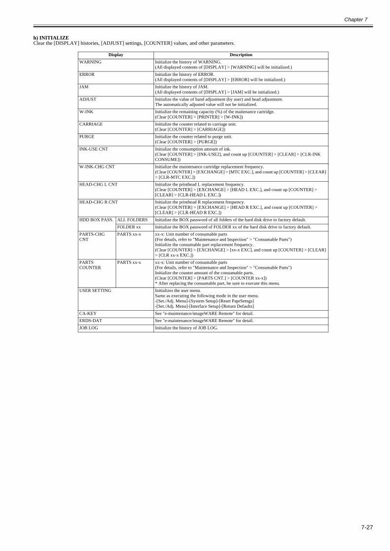
Chapter 7
7-27
h) INITIALIZEClear the [DISPLAY] histories, [ADJUST] settings, [COUNTER] values, and other parameters.
Display DescriptionWARNING Initialize the history of WARNING.
(All displayed contents of [DISPLAY] > [WARNING] will be initialized.)ERROR Initialize the history of ERROR.
(All displayed contents of [DISPLAY] > [ERROR] will be initialized.)JAM Initialize the history of JAM.
(All displayed contents of [DISPLAY] > [JAM] will be initialized.)ADJUST Initialize the value of band adjustment (by user) and head adjustment.
The automatically adjusted value will not be initialized.W-INK Initialize the remaining capacity (%) of the maitenance cartridge.
(Clear [COUNTER] > [PRINTER] > [W-INK]) CARRIAGE Initialize the counter related to carriage unit.
(Clear [COUNTER] > [CARRIAGE])PURGE Initialize the counter related to purge unit.
(Clear [COUNTER] > [PURGE])INK-USE CNT Initialize the consumption amount of ink.
(Clear [COUNTER] > [INK-USE2], and count up [COUNTER] > [CLEAR] > [CLR-INK CONSUME])
W-INK-CHG CNT Initialize the maintenance cartridge replacement frequency.(Clear [COUNTER] > [EXCHANGE] > [MTC EXC.], and count up [COUNTER] > [CLEAR] > [CLR-MTC EXC.])
HEAD-CHG L CNT Initialize the printhead L replacement frequency.(Clear [COUNTER] > [EXCHANGE] > [HEAD L EXC.], and count up [COUNTER] > [CLEAR] > [CLR-HEAD L EXC.])
HEAD-CHG R CNT Initialize the printhead R replacement frequency.(Clear [COUNTER] > [EXCHANGE] > [HEAD R EXC.], and count up [COUNTER] > [CLEAR] > [CLR-HEAD R EXC.])
HDD BOX PASS. ALL FOLDERS Initialize the BOX password of all folders of the hard disk drive to factory default.FOLDER xx Initialize the BOX password of FOLDER xx of the hard disk drive to factory default.
PARTS-CHG CNT
PARTS xx-x xx-x: Unit number of consumable parts(For details, refer to "Maintenance and Inspection" > "Consumable Parts")Initialize the consumable part replacement frequency.(Clear [COUNTER] > [EXCHANGE] > [xx-x EXC], and count up [COUNTER] > [CLEAR] > [CLR xx-x EXC.])
PARTS COUNTER
PARTS xx-x xx-x: Unit number of consumable parts(For details, refer to "Maintenance and Inspection" > "Consumable Parts")Initialize the counter amount of the consumable parts. (Clear [COUNTER] > [PARTS CNT.] > [COUNTER xx-x])* After replacing the consumable part, be sure to execute this menu.
USER SETTING Initializes the user menu.Same as executing the following mode in the user menu.-[Set./Adj. Menu]-[System Setup]-[Reset PaprSetngs]-[Set./Adj. Menu]-[Interface Setup]-[Return Defaults]
CA-KEY See "e-maintenance/imageWARE Remote" for detail.ERDS-DAT See "e-maintenance/imageWARE Remote" for detail.JOB LOG Initialize the history of JOB LOG.

Chapter 7
7-28
7.1.4 e-Maintenance/imageWARE Remote0023-1100
1. OverviewThe e-Maintenance/imageWARE Remote system allows a customer's device information and status to be monitored via the Internet on a server called the UGW(Universal Gateway) Server.
The following device information/ statuses can be monitored.- Service mode counters - Parts counters- Mode counters- Firmware information- Service call errors log- Jam log- Alarm log- Alert change statuses (Toner/ ink low/ out, etc.)
Device monitor information above is sent by the e-RDS (embedded Remote Diagnostic System), which is embedded in the devices.
Further, as the above is all customer information, https SOAP protocol is used for communication between the UGW and the device, providing enhanced security(SSL client communication)
F-7-232. Feature and benefitsDevice (e-RDS) embedded with network module can realize a front-end processing of the e-Maintenance/imageWARE Remote system without attaching an extrahardware equipment.The e-Maintenance/imageWARE Remote system can be implemented without imposing a burden on the users.
3. Settings procedures3.1 Advance preparationsTo monitor the device with e-Maintenance/imageWARE Remote, the following settings are required.
1) Advance confirmationCheck with the UGW administrator whether the printer to be connected to the e-Maintenance/imageWARE remotely has been registered in the UGW.
2) Advance preparationsInterview the user's system administrator in advance to find out the following information about the network.
Information item -1IP address setting methodsCheck whether automatic setting or manual setting is to be used, and confirm the information below.- Automatic setting: (DHCP, RARP, BOOTP) (ON/OFF selection)or- Manual setting: IP address, subnet mask and gateway address to be set
Information item -2Is there a DNS server in use?If there is a DNS server in use, find out the following.- Primary DNS server address- Secondary DNS server address (optional)
Information item -3Is there a proxy server?If there is a proxy server in use, find out the following.- Proxy server address- Port number connected to proxy server
Information item -4Is proxy server authentication required?If proxy server authentication is required, find out the following.- User name and password required for proxy authentication
3) Network settingsMake the network settings based on the information obtained in "2) Advance preparations."Network settings are made in user mode. Therefore, it is assumed that the user has already set it. However, there are a few cautions as described below, and ifnecessary, there may be cases in which the service technicians do it after obtaining an approval from user.
Caution point -1Proxy server settingsProxy server settings cannot be made in "Remote UI". Enter from the operation panel menu. In addition, the operation panel menu items for proxy server only appearwhen e-RDS functions are enabled. Therefore, when you make proxy server settings, turn the "E-RDS SWITCH" setting to "ON" as described in later sectionsbeforehand.
Caution point -2Validate the settings (restart the printer)
UGW
e-RDS

Chapter 7
7-29
The server address settings are activated only after you restart the printer. Make sure you always restart the printer after changing server address settings.
(1) How to enter Proxy server address
F-7-24
- Following symbols exist in each enter mode. (When you press the key, characters on the right hand side will appear.) [a] Small alphabet letter mode: [Symbol] abcdefghijklmnopqrstuvwxyz [A] Capital alphabet letter mode: [Symbol] ABCDEFGHIJKLMNOPQRSTUVWXYZ [1] Numerical character mode: [Symbol] 1234567890
- [Symbol] appears in the following order.
F-7-25
- Within the URL entry field, you can use the or key to select a character, and the or key to move the cursor.- The Stop key has the Delete function when there is a character at the cursor position. (The character at the position of the cursor is deleted, moving all followingcharacters one position toward freed place.) If there is no character at the cursor position, it has the Backspace function. (The character at the left of the cursor is deleted, moving the cursor.)- When you move the cursor to a position of a character and press the or key, you can insert characters.(The character at the cursor position is moved to the right, and a new character is inserted.- You can select the enter mode with the Navi key. (The default setting is small alphabet letter.)
(2) How to enter port number
F-7-26- Possible to set between 1 and 65535 (The default display is 1).- The top digit can be selected between 0 and 6. Other digits can be selected between 0 and 9.- When OK key is pressed, and the value is over 65535, it is fixed on 65535.- When OK key is pressed, and the value is 0, it is fixed on 1.
[1] Display to show enter modea: Small alphabet letterA: Capital alphabet letter1: Numerical character
[2] URL entry field (128 one-byte characters)
Server Address
h t t p : / / _
[a]
: S e l e c t
S t o p : D e l e t e
N a v i : a -> A -> 1
[ O K : S e t ]
[1]
[2]
key key
Port Number
0 0 0 0 1
( 1 - 6 5 5 3 5 )
L / R
U P / D O W N
[ OK : S e t ]

Chapter 7
7-30
(3) How to enter user name
F-7-27
- It is the same as the entering method of proxy server address.
(4) How to enter password
F-7-28
- If a password has already been set, when you press the or key at any cursor position, all the "*" will disappear and the first letter will be entered as the firstcharacter.- Entered characters are visible until you press OK key. Once entering into the menu again, they will be changed to "*".- Other information is the same as the entering method of proxy server address.
3.2 e-RDS settings1) Enter the service mode.- Turn off the printer power.- Turn on the power while pressing the [Load] key and [Navigate] key. * Keep pressing the above keys until "Initializing" is displayed.- "S" appears at the top right of the display.- Press the or key to choose the [Set./Adj. Menu]and press the [OK] key. * "SERVICE MODE" appears in the menu list and the MESSAGE LED flashes.- Press the key or key to choose "SERVICE MODE" and press the [OK] key.
2) Set the following e-RDS setting items No.1-4.(If the result of the communication test (COM-TEST) is "NG", execute setting items No.5-6 to solve the problem.)
[1] Entry filed (24 one-byte characters)
[1] Entry filed (24 one-byte characters)
No. Item Type Description1 E-RDS SWITCH 2 bytes OFF : Disable/ ON : Enable e-Maintenance/ imageWARE Remote system to send device information,
meter data, and error statuses to the UGW.Default value is OFF (not in use)
2 UGW-ADDRESS 129 bytes (NULL included, SJIS not allowed)
The UGW address by default : https://a01---.The complete address is not provided in this document for security reason.
3 UGW-PORT 4 bytes The UGW Port Number by default : 443Validation : 1-65535
4 COM-TEST To perform Communication test with UGW and set "OK!"/ "NG!" as the result.5 COM-LOG Detailed communication data log
Switches to display time when error occurred, error code, and error data up to now.Max 30 loggings retained.Max 128 characters (not containing NULL) for Error information.
6 ERDS-DAT Initialize e-RDS setting data
Proxy User
User Name Canon
[a]
: S e l e c t
S t o p : D e l e t e
N a v i : a -> A -> 1
[ O K : S e t ]
[1]
Proxy Password [a]
: S e l e c t
S t o p : D e l e t e
N a v i : a -> A -> 1
[ OK : S e t ]
[1]

Chapter 7
7-31
3.3 Service Mode Menu Tree
* Press key to move to the next menu of the same layer, and press key to move to the menu of one layer deeper. * The menus shown in '*1' are the e-RDS-related menus.
3.4 e-RDS Related Setting Details 1) e-RDS's Operation Mode [E-RDS SWITCH] In service mode, referring to the "Service Mode Menu Tree", go to [E-RDS SWITCH] menu using key and key.
(1) Choose between [ON] or [OFF] using the and keys.
F-7-29
(2) Press [OK] key to determine the operation mode and go back to the previous screen.
F-7-30 - When the operation mode is determined, "=" will be displayed. - OFF: When it is set to [OFF], e-RDS is not used. Default value is OFF. - ON: When it is set to [ON], e-RDS is used.
First Level Second Level Third Level Fourth Level Fifth Level Sixth LevelDISPLAYI/O DISPLAYADJUSTFUNCTIONREPLACECOUNTERSETTEING Pth
RTCPV AUTO JUDGENETWORK CERTIFICATE CA-CERTIFICATE VALIDITY:*1 yyyy/mm/ddE-RDS E-RDS SWITCH:*1 ON/OFF
UGW-ADDRESS:*1 http://XXXUGW-PORT:*1 XXXXXCOM-TEST:*1 YESCOM-LOG:*1
HEAD DOT INFINITIALIZE WARNING
ERRORJAMADJUSTW-INKCARRIAGEPURGEINK-USE CNTW-INK-CHG CNTHEAD-CHG CNTHDD BOX PASSPARTS-CHG CNTPARTS COUNTERUSER SETTEINGCA-KEY:*1 YES/NOERDS-DAT:*1 YES/NOJOB LOG YES/NO
O F F
E - R D S S W I T C H
= O N
E - R D S S W I T C H

Chapter 7
7-32
2) UGW Address [UGW-ADDRESS] and UGW port [UGW-PORT] Usually, the default values set in advance are used for the setting value of [UGW-ADDRESS] and [UGW-PORT]. Unless there is a special instruction, the defaultvalue should not be changed. If it should be changed, the communication with UGW may have an error. If [UGW-ADDRESS] and [UGW-PORT] are changed, thenew setting will be enabled after power OFF/ON.Therefore, usually, the setup is not necessary.* If you change under a special instruction, perform the following procedure.
(1) Setting address for UGW - In service mode, referring to the "Service Mode Menu Tree", go to [UGW-ADDRESS] menu using key and key.
F-7-31
- Press key to enter the Setup Mode. (A character indicating the input mode (in the upper right corner of the screen) and the cursor are displayed.) Enter UGW address (URL).
F-7-32 Display to indicate an input mode A: Alphabet capital letter a: Alphabet small letter 1: Numerical character - The cursor is shown at the first letter. - Use and keys to select characters to enter. - Press [Back] key to cancel what you entered and go back to the previous screen. - Press [OK] key to determine what you entered and go back to the previous screen.
(2) Setting up the GW Port Number - In service mode, referring to the "Service Mode Menu Tree", go to [UGW-PORT] menu using key and key.
F-7-33
- Press key to enter the Setup Mode. (A cursor is displayed.) Enter a port number.
F-7-34
- Use and keys to select characters to enter. - Press [Back] key to cancel what you entered and go back to the previous screen. - Press [OK] key to determine what you entered and go back to the previous screen.
* The actual setting value of UGW address [UGW-ADDRESS] and UGW port [UGW-PORT] are categorized as confidential information, so they are not describedin this manual.
3) Communication Test [COM-TEST] (1) In service mode, referring to the "Service Mode Menu Tree", go to [COM-TEST] menu using key and key.
F-7-35
(2) Press [OK] key to start the test. ("=" is displayed at the start of the test.)
F-7-36
(3) During the communication test, "CHECK NOW" is displayed.
F-7-37
U G W A D D R E S S
E - R D S
U G W A D D R E S S
h t t p : / /
: a-
U G W P O R T
E - R D S
U G W P O R T
0 0 0 0 0
-
Y E S
C O M - T E S T
= Y E S
C O M - T E S T
C H E C K N O W . .
C O M - T E S T

Chapter 7
7-33
- Once the communication test is started, it cannot be cancelled.(Other operation won't be accepted until the result is obtained.)
(4) If the communication test was successful, "CHECK RSLT:OK" is displayed.
F-7-38
- Press key to exit this operation mode and go back to the top of [COM-TEST] menu.
(5) If the communication test was failed, "CHECK RSLT:NG" is displayed.
F-7-39
- Press key to exit this operation mode and go back to the top of [COM-TEST] menu. - If you cannot obtain the result after 30 seconds from the start of a communication test, the test is considered failed and the same screen will appear.
* When the communication test was successful, it is necessary to take the interval of 5 minutes before performing the next communication test.
4) Communication Log [COM-LOG]Communication Error Information/Detailed Communication Error Information can be displayed on the screen at the time of a communication error with the ServiceCenter (including proxy server error). When a communication error occurs, you can refer to this information to study how to deal with the problem. * For the countermeasure corresponding to each Communication Error Information or Detailed Communication Error Information, see the list of error message in"4. Troubleshoot".
(1) In service mode, referring to the "Service Mode Menu Tree", go to [COM-LOG] menu using key and key.
F-7-40
(2) Press key, and communication error information is displayed. On the upper line of the LCD, a log number (01-30) and an error code are shown; on thebottom line, an occurrence date and time of the error is shown.
F-7-41 - COM-LOG information can be saved up to 30 cases. - Use Right and Left keys to change logs to display. - Logs are displayed in the sequence of the time of occurrence. (Log number 1 is the latest log.) - Press key to exit this operation mode and go back to the top of [COM-LOG] menu. * If the Communication Error Information is not saved, the screen below will appear.
F-7-42
- Press key to exit the communication error information screen and go back to the top of [COM-LOG] menu.
(3) Press key to display the Detailed Communication Error Information (maximum 128 characters).
1st-32nd characters of Detailed Communication Error Information are shown.
F-7-43 33rd-64th characters of Detailed Communication Error Information are shown.
F-7-44
C H E C K R S L T : O K
C O M - T E S T
C H E C K R S L T : N G
C O M - T E S T
C O M - L O G
E - R D S
Y Y Y Y / M M / D D H H : M M
N o : 0 1 X X X X X X X X H
N O L O G
C O M - L O G
X X X X X X X X X X X X X X X X
X X X X X X X X X X X X X X X X
X X X X X X X X X X X X X X X X
X X X X X X X X X X X X X X X X
Chapter 7
7-34
65th-96th characters of Detailed Communication Error Information are shown.
F-7-45 97th-128th characters of Detailed Communication Error Information are shown.
F-7-46
- Use and keys to move among Screen and Screen. (Detailed Communication Error Information can be made with maximum 128 characters, however, evenif the information is made up with 1 to 96 characters, all Screens are still displayed.) - Press key to exit the Detailed Communication Error Information screen and go back to the Communication Error Information screen.
* If Detailed Communication Error Information does not exist, the screen below will appear.
F-7-47
- Press key to exit the Detailed Communication Error Information screen and go back to the Communication Error Information screen.
5) Initializing the e-RDS setting [ERDS-DAT] Usually, the setup is not necessary.Use this procedure when you want to reset the e-RDS settings to the factory default.
(1) In service mode, referring to the "Service Mode Menu Tree", go to [ERDS-DAT] menu using key and key.
F-7-48
(2) Choose between YES/NO using and keys, and press [OK] key to set.
F-7-49 - Press [OK] key, and "=" will appear and the initializing process will begin.
[NO]: Do not initialize the e-RDS setting. Default value is [NO]. [YES]: Initialize the e-RDS setting.
6) Displaying the CA Certificate Information [VALIDITY] For the secure communication between the device (e-RDS) and the UGW, an authentication technology from a certification authority is used. A license has beenissued from the certification authority. For this reason, the devices are shipped with the CA (Certificate Authority) certificate enabled in advance to prove the licenseobtained.
Therefore, usually, the setup is not necessary.
To confirm that this CA certificate is valid or how long it will be valid, you can display the expiration date of the CA certificate information.
(1) In service mode, referring to the "Service Mode Menu Tree", go to [VALIDITY] menu using key and key.
F-7-50
(2) Press key, and the expiration date of the CA certificate will be displayed.
F-7-51
X X X X X X X X X X X X X X X X
X X X X X X X X X X X X X X X X
X X X X X X X X X X X X X X X X
X X X X X X X X X X X X X X X X
N O E R R O R D E T A I L
N O
E - R D S D A T
= Y E S
E - R D S D A T
V A L I D I T Y
C A - C E R T I F I C A T E
Y Y Y Y / M M / D D
V A L I D I T Y

Chapter 7
7-35
- Press key to exit the CA certificate expiration date display screen and go back to the top of [VALIDITY] menu.
* If the CA certificate is deleted, the screen below will appear.
F-7-52
- Press key to exit the CA certificate expiration date display screen and go back to the top of [VALIDITY] menu.
7) Deleting the CA Certificate [CA-KEY] For the secure communication between the device (e-RDS) and the UGW, an authentication technology from a certification authority is used. A license has beenissued from the certification authority. For this reason, the devices are shipped with the CA (Certificate Authority) certificate enabled in advance to prove the licenseobtained.The device (e-RDS) uses this CA certificate to communicate with the UGW, thus CA must not be deleted.
Therefore, usually, the setup is not necessary.
* If you delete the CA certificate under a special instruction, perform the following procedure.
(1) In service mode, referring to the "Service Mode Menu Tree", go to [CA-KEY] menu using key and key.
F-7-53
(2) Choose between YES/NO using and keys, and press [OK] key to set.
F-7-54 - Press [OK] key, and "=" will appear and the initializing process will begin.
[NO]: Do not delete the CA certificate. Default value is [NO]. [YES]: Delete the CA certificate.
N O T I N S T A L L E D
V A L I D I T Y
N O
C A - K E Y
= Y E S
C A - K E Y

Chapter 7
7-36
4. FAQ
5. Troubleshooting
No. Question AnswerQ1 Registration information of the device (E-RDS) is once
deleted from the UGW server, and is re-registered after that. If a communication test is notcarried out, then device information on UGW becomes invalid.
When registration of the device (e-RDS) is deleted from the UGW, the status will be changed to the communication test not completed because relatedinformation has lost from a database. Therefore, device information will also become invalid if that condition persists for seven days without carrying out the communicationtest. Hence, to avoid the invalid condition, carry out the communication test.
Q2 The communication test with the UGW server results NG! The comunication test might become NG in the following cases.- 1. Name resolution was failed due to an incorrect host name or DNS server has been halted.- 2. Network cable is blocked off. Network cable is broken.- 3. Proxy server settings are not correct.
Q3 Could you describe the timing of data transmitting from the device (e-RDS) to the UGW, and what data size is sent to the UGW?
The schedule of data transmitting, and the start time are determined by settings in the UGW side. The timing is once per 16 hours by default, and counter data size is maximum 1400 bytes.
Q4 Can I turn the device power off during the device (e-RDS) operation?
While operating the device (e-RDS), the power of the printer and network equipment such as HUB must be ON. If power OFF is needed, do not leave it OFF for a long time.An error such as "Device is busy, try later"could occur if the power supply of networkequipment is made prolonged OFF.
No. Condition detected Action1 The communication test has failed. Check network conditions such as proxy server settings and so on.
- Check the communication log from COM-LOG. -> Execute "Remedy" in the "Error message list".- Check whether RGW-ADDRESS or RGW-PORT settings have changed.

Chapter 7
7-37
6. Error message listDetails of the errors and their remedies are as described below.(The meaning of server indicates the UGW in this section)
*1:[Hexadecimal] indicates an error code returned from the UGW in hexadecimal.
7. Service cautionsAfter performing the following service actions, it is necessary to perform the resetting of the e-RDS.Failure to do so will result that the counter transmitting value to the UGW may become unusual.
- System software (firmware) upgrade- After replacing the main controller board, the following settings in service mode must not be changed unless there are specific instructions to do so. Changingthese values will cause error in communication with the UGW.
(Initial values)UGW-PORT: 443UGW-ADDRESS: https://a01---.
No. Error Message Cause Remedy1 SUSPEND:
Communication test is not performed
E-RDS has been booted up (device reboot) with E-RDS SWITCH = ON but thecommunication test had not yet been performed.
Perform the communication test [COMTEST] in service mode.
2 Event Registration is Failed Event Registration is Failed Processing (event processing) within the device has failed.
Turn the device OFF/ ON. If the error persists, replace the device system software (firmware).(Upgrade)
3 URL Scheme error (not https) The header of the URL of the registered UGW is not in https format. A "https://" input error.
Check that the value of UGW-ADR has been entered correctly as https://a01---.
4 Server connection error An UGW connection error. Displayed in the event of a TCP/IP communication fault.
Check the network-related settings according to "No.1: Communication test is not performed" in "Troubleshooting".
5 URL server specified is illegal A URL different to that specified by the UGW has been set. An URL address setting error.
Check that the value of UGW-ADR has been entered correctly as https://a01---.
6 Proxy connection error Cannot connect to proxy server.Displayed when unable to connect to proxy server.
Check proxy server address and re-enter if necessary.
7 Proxy authentication error Displayed when the authentication to the proxy server has failed.
Check the user name and password required in order to login to the proxy, and re-enter if necessary.
8 Server certificate error Device's route certificate is unavailable. Reinstall the latest device system software (firmware). (Upgrade)
9 Server certificate expired The route certificate registered with the device has expired.
Check that the device time and date are correctly set. If the device time and date are correct, upgrade to the latest system software (firmware).
10 Unknown error Some other kind of communication error has occurred.
Try again after a period of time. If the same error occurs again, check the UGW status with the UGW administrator.
11 SOAP Fault SOAP communication error has occurred. Check that the value of UGW-PORT is 443.12 Server response error (NULL) A UGW response error (when UGW error code
processing has failed).A HTTPS communication error.
Try again after a period of time. If the same error persists, check the UGW status with the UGW administrator.
13 Server response error (Hexadecimal)[Error detailed in the UGW]:*1
A UGW response error.Displayed when communication with UGW has been successful, but an error of some sort has prevented UGW from responding.
Check an error code (hexadecimal) returned from the UGW, then retry after a period of time.
14 Device internal error An internal device error. An error due to the device side.
Switch the device OFF/ ON. Or, replace the device system software. (Upgrade)
15 Server schedule is invalid During the communication test, there has been some kind of error in the schedule values passed from UGW.
When the error occurs, report the details to the support department. Then, after the UGW side has responded, retry the communication test.
16 Server response time out UGW response time out.Due to network congestion, etc., the response from UGW does not come within the specified time.
If this error occurs when the communication test is being run, wait some time and rerun the test.
17 Server not found There is a mistake in the UGW URL, and UGW cannot be accessed.
Check that the value of Service mode > E-RDS/RGW-ADR is https://a01---.
18 E-RDS switch is set OFF E-RDS is disabled. Set E-RDS SWITCH = ON, and run COM-TEST in service mode.
19 Server schedule is not exist Server schedule does not exist.Blank schedule data has been received from UGW.
Check the device settings status with the UGW administrator.
20 Network is not ready, try later Network-related settings have not been made for the device.
Make network-related settings properly for the device (printer).
21 URL error A URL setting error.Non-URL text string entered in URL field.
Check that the value of UGW-ADR is https://a01---.
22 Proxy address resolution error A proxy server address resolution error. Check that the proxy server name is correct.23 Server certificate verify error The server certificate verification (URL check)
error.Check that the value of UGW-ADR is https://a01---.
24 Server address resolution error UGW address resolution has failed. Check that the value of UGW-ADR is https:// a01---.

Chapter 7
7-38
7.1.5 Viewing PRINT INF0026-6836
a) PRINT INF item detailThe details of each PRINT INF item displayed when performing [SERVICE MODE] > [DISPLAY] > [PRINTINF] are as follows:
Print item Print content Printed valueSYSTEM S/N Serial number of printer characters/numerals of 8-byte
TYPE Type setting on main controller PCB 44LF TYPE Feed roller type 0: old type roller
1: new type rollerTMP Ambient temperature Unit: Centigrade degreeRH Ambient humidity Unit: %SIZE LF Detected size of loaded media (feed direction) mm (0 is always detected for the roll media.)SIZE CR Detected size of loaded media (carriage scan direction) mmAFTER INST. Number of days since initial installation Unit: Day(s)
HEAD S/N L Serial number of printhead L characters/numerals (8 digits)S/N R Serial number of printhead R characters/numerals (8 digits)LOT L Lot number of printhead L characters/numerals (8 digits)LOT R Lot number of printhead R characters/numerals (8 digits)
INK BK, MBK, C, M, Y, PC, PM, GY
Number of days passed since the ink tank was installed Unit: Days
WARNING 01 to 20 Warning history (up to 20 events) Number: Lowest is the most recentDate: mm/ddTime: mm/ssCode: Last 4 digitsCumulative number of printed media (equivalent of A4)
ERROR 01 to 20 Error history (up to 20 events) Number: Lowest is the most recentDate: mm/ddTime: mm/ssCode: Last 4 digitsCumulative number of printed media (equivalent of A4)

Chapter 7
7-39
Print item Print content Printed valueJOB CONDITION 01-05 Job history (up to 5 events) Number: Lowest is the most recent
1 Print mode 1: [Image]-[Highest] (Image high-precision)2: [Image]-[Highest] (Line dwawing and text high-precision)3: [Image]-[Highest]4: [Image]-[High] (Line dwawing and text high-precision) or [Line Drawing/Text]-[High]5: [Image]-[High]6: [Image]-[Standard] (Line dwawing and text high-precision) or [Line Drawing/Text]-[Standard]7: [Image]-[Standard]8: [Line Drawing/Text]-[Draft]9: [Image]-[Draft]10: [Image]-[Draft] (Economy) or [Office Document]-[Standard]11: Exception mode
2 Head height a(n)- Description of "a"A: Automatic settingH: Fixed setting- Description of "n"0: SL(1.2mm)1: L(1.4mm)2: M1(1.8mm)3: M2(2.0mm)4: M3(2.2mm)5: H(2.6mm)*: Unknown
3 Temperature and humidity4 Media type Display media name
*: Unknown5 Printing date & time6 Job name Name stored to the HDD7 Registration condition A: The gap used to the printing matches with the gap of
inner registration adjustment value.B: The gap used to the printing don't match with the gap of inner registration adjustment value.C: There is no registration adjustment value.
HEAD ADJUSTMENT
01-05 Adjustment history (up to 5 events) Number: Lowest is the most recent1 Adjustment type manu: Manual adjustment
auto(d): Automatic adjustment (detail)auto(s): Automatic adjustment (standard)auto(e): Automatic adjustment (expansion)
2 Head height a(n)- Description of "a"A: Automatic settingH: Fixed settingAE: Adjustment error (automatic setting)HE: Adjustment error (fixed setting)- Description of "m"(Gap1) and "n"(Gap2)0: SL(1.2mm)1: L(1.4mm)2: M1(1.8mm)3: M2(2.0mm)4: M3(2.2mm)5: H(2.6mm)-: Not executed*: Unknown
3 Temperature and humidity4 Media type Display media name
*: Unknown5 Printing date & time6 Gap distance between head and media

Chapter 7
7-40
Print item Print content Printed valueJAM 01 to 05 JAM log (5 records) Number: Lowest is the most recent
Date: mm/ddTime: mm/ssJam code
1 Jam type 1: CR error2: Jam3: Feed failure (delay)4: Cut failure*: Unknown
2 Media format 1: Roll media2: Cut sheet (manual feed from top)3: Cut sheet (manual feed from front)4: Cassette*: Unknown
3 Jam timing 1: Feed 2: Print3: Eject*: Unknown
4 Width detection OFF mode 1: ON2: OFF*: Unknown
5 Head height 0: SL (1.2mm)1: L (1.4mm)2: M1 (1.8mm)3: M2 (2.0mm)4: M3 (2.2mm)5: H (2.6mm)*: Unknown
6 (Not Used)7 Cut mode 1: User cut
2: Eject cut3: Auto cut*: Unknown
8 Media passing environment 0: A(temperature 15 to 25 degrees centigrade/humidity 40 to 60%)1: B(temperature 25 to 30 degrees centigrade/humidity 40 to 60%)2: C(temperature 15 to 30 degrees centigrade/humidity 10 to 40%)3: D(temperature 15 to 30 degrees centigrade/humidity 60 to 80%)4: E(temperature 15 to 30 degrees centigrade/humidity 0 to 10%, or 15 degrees centigrade or less and 30 degrees centigrade or more/humidity 0 to 50%[low humidity is out of guarantee.])5: F(temperature 15 to 30 degrees centigrade/humidity 80 to 100%, or 15 degrees centigrade or less and 30 degrees centigrade or more/humidity 50 to 100%[high humidity is out of guarantee.])*: Unknown
9 Borderless/Bordered 1: Bordered printing2: Borderless printing*: Unknown
10 (Not Used)11 Print mode label No. Display print mode
*: Unknown12 Media width Display media width (Unit: mm)
*: Unknown13 Media type Display media name
*: UnknownINK CHK BK, MBK, C, M,
Y, PC, PM, GYRefill logPrint whether disable remaining ink detection was previously set
0: Disable remaining ink detection was never set1: Disable remaining ink detection was set at least once

Chapter 7
7-41
Print item Print content Printed valueCOUNTER PRINTER POWER ON Cumulative power-on time Unit: hours
SLEEP ON Cumulative sleep-on time Unit: hoursCUTTER Number of cutting operations Unit: timesWIPE Number of wiping operations Unit: timesW-INK Remaining capacity of the maintenance cartridge Unit: %PDL Cumulative number of printed media according to PDL GARO: xx sheets
HP-GL/2: xx sheetsCARRIAGE PRINT Cumulative printing time Unit: hours
DRIVE Cumulative carriage moving time Unit: hoursCR-COUNT Cumulative carriage scan count (count as 1 by moving back
and forth)Unit: times
CR-DIST. Cumulative carriage scan distance (count as 1 by moving 210mm)
Unit: times
PRINT-COUNT Cumulative print end count (count as 1 by capping) Unit: timesPURGE CLN-A Cumulative number of automatic cleaning operations
1 Cumulative number of automatic cleaning 1 (normal suction) operations
Unit: times
2 Cumulative number of automatic cleaning 2 (ink level adjusting) operations
3 Cumulative number of automatic cleaning 3 (initial filling) operations
6 Cumulative number of automatic cleaning 6 (strong normal suction) operations
7 Cumulative number of automatic cleaning 7 (aging) operations
8 Cumulative number of automatic cleaning 8 (flashing) operations
10 Cumulative number of automatic cleaning 10 (ink filling after secondary transportation) operations
11 Cumulative number of automatic cleaning 11 (ink filling after head replacement) operations
15 Cumulative number of automatic cleaning 15 (dot count small suction) operations
16 Cumulative number of automatic cleaning 16 (sedimented ink agitation) operations
17 Cumulative number of automatic cleaning 17 (small suction) operations
TTL Total number of automatic cleaning operationsCLN-M Cumulative number of manual cleaning 1 operations1 Cumulative number of manual cleaning 1 (normal suction)
operationsUnit: times
4 Cumulative number of manual cleaning 4 (ink draining from head after head replacement) operations
5 Cumulative number of manual cleaning 5 (ink draining from head and tube before transportation ) operations
6 Cumulative number of manual cleaning 6 (normal strong suction) operations
TTL Total number of manual cleaning operations

Chapter 7
7-42
Print item Print content Printed valueCOUNTER CLEAR INK CONSUME Cumulative count of ink section consumption amount
clearingUnit: times
MTC EXC. Cumulative count of maintenance cartridge replacement count clearing
HEAD L EXC. Cumulative count of printhead L replacement count clearing HEAD R EXC. Cumulative count of printhead R replacement count clearing PARTS Wia-1 EXC.
Cumulative count of unit Wia-1 (waste ink box unit) replacement count clearing
PARTS Wia-3 EXC.
Cumulative count of unit Wia-3 (platen ink box unit) replacement count clearing
PARTS Wia-4 EXC.
Cumulative count of unit Wia-4 (platen ink box unit) replacement count clearing
PARTS Wia-5 EXC.
Cumulative count of unit Wia-5 (platen ink box unit) replacement count clearing
PARTS Wia-6 EXC.
Cumulative count of unit Wia-6 (suction fan unit) replacement count clearing
PARTS CR-1 EXC.
Cumulative count of unit CR-1 (carriage unit bushing) replacement count clearing
PARTS CR-2 EXC.
Cumulative count of unit CR-2 (linear encoder sensor/linear scale/shaft cleaner) replacement count clearing
PARTS CR-3 EXC.
Cumulative count of unit CR-3 (carriage height changing cam) replacement count clearing
PARTS CR-4 EXC.
Cumulative count of unit CR-4 (ink tube unit/flexible cable unit) replacement count clearing
PARTS CR-5 EXC.
Cumulative count of unit CR-5 (multi sensor) replacement count clearing
PARTS PG-1 EXC.
Cumulative count of unit PG-1 (purge unit) replacement count clearing
PARTS HMa-1 EXC.
Cumulative count of unit HMa-1 (head management sensor) replacement count clearing
PARTS PL-1 EXC.
Cumulative count of unit PL-1 (carriage motor) replacement count clearing
PARTS PS-1 EXC. Cumulative count of unit PS-1 (feed motor) replacement count clearing
PARTS Mi-1 EXC.
Cumulative count of unit Mi-1 (mist fan) replacement count clearing
PARTS MS-1 EXC.
Cumulative count of unit MS-1 (multi sensor) replacement count clearing
FACTORY CNT. For factory
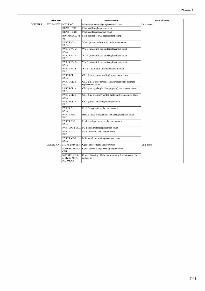
Chapter 7
7-43
Print item Print content Printed valueCOUNTER EXCHANGE MTC EXC. Maintenance cartridge replacement count Unit: times
HEAD L EXC. Printhead L replacement countHEAD R EXC. Printhead R replacement countBOARD EXC.(M/B)
Main controller PCB replacement count
PARTS Wia-1 EXC.
Wia-1 (waste ink box unit) replacement count
PARTS Wia-3 EXC.
Wia-3 (platen ink box unit) replacement count
PARTS Wia-4 EXC.
Wia-4 (platen ink box unit) replacement count
PARTS Wia-5 EXC.
Wia-5 (platen ink box unit) replacement count
PARTS Wia-6 EXC.
Wia-6 (suction fan unit) replacement count
PARTS CR-1 EXC.
CR-1 (carriage unit bushing) replacement count
PARTS CR-2 EXC.
CR-2 (linear encoder sensor/linear scale/shaft cleaner) replacement count
PARTS CR-3 EXC.
CR-3 (carriage height changing cam) replacement count
PARTS CR-4 EXC.
CR-4 (ink tube unit/flexible cable unit) replacement count
PARTS CR-5 EXC.
CR-5 (multi sensor) replacement count
PARTS PG-1 EXC.
PG-1 (purge unit) replacement count
PARTS HMa-1 EXC.
HMa-1 (head management sensor) replacement count
PARTS PL-1 EXC.
PL-1 (carriage motor) replacement count
PARTS PS-1 EXC. PS-1 (feed motor) replacement countPARTS Mi-1 EXC.
Mi-1 (mist fan) replacement count
PARTS MS-1 EXC.
MS-1 (multi sensor) replacement count
DETAIL-CNT MOVE PRINTER Count of secondary transportation Unit: timesMEDIACONFIG-CNT
Count of media registered by media editor
N-INKCHK BK, MBK, C, M, Y, PC, PM, GY
Count of turning off the ink remaining level detection for each color

Chapter 7
7-44
Print item Print content Printed valueCOUNTER INK-USE1 INK BK, MBK, C,
M, Y, PC, PM, GYCumulative consumption amount of generic ink Unit: ml
TTL Total amount of the cumulative consumption of generic inkLINK BK, MBK, C, M, Y, PC, PM, GY
Cumulative consumption amount of generic large ink
TTL Total amount of the cumulative consumption of generic large ink
SINK BK, MBK, C, M, Y, PC, PM, GY
Cumulative consumption amount of generic small ink
TTL Total amount of the cumulative consumption of generic small ink
NINK BK, MBK, C, M, Y, PC, PM, GY
Cumulative consumption amount of refilled ink
TTL Total amount of the cumulative consumption of refilled inkINK-USE2 INK BK, MBK, C,
M, Y, PC, PM, GYConsumption amount of generic ink of the currently installed ink tank.
Unit: ml
TTL Total consumption amount of generic ink of the currently installed ink tanks
NINK BK, MBK, C, M, Y, PC, PM, GY
Consumption amount of refilled ink of the currently installed ink tank
TTL Total consumption amount of refilled ink of the currently installed ink tanks
INK-EXC INK BK, MBK, C, M, Y, PC, PM, GY
Cumulative count of generic ink tank replacement Unit: times
TTL Total amount of the cumulative count of generic ink tank replacement
NINK BK, MBK, C, M, Y, PC, PM, GY
Cumulative count of refilled ink tank replacement
TTL Total amount of the cumulative count of refilled ink tank replacement

Chapter 7
7-45
Print item Print content Printed valueCOUNTER MEDIA 1-7 NAME Media type
TTL Total amount of cumulative print area of roll media and cut sheet
Unit: square/meter, square/feet
ROLL Cumulative print area of roll mediaCUTSHEET Cumulative print area of cut sheet
MEDIA OTHER
NAME OTHER OTHERTTL Total amount of cumulative print area of roll media and cut
sheetUnit: square/meter, square/feet
ROLL Cumulative print area of roll mediaCUTSHEET Cumulative print area of cut sheet
MEDIA SIZE1 ROLL P-SQ/P-CNT
44-60 Cumulative print area of roll media equal to or larger than 44 inches but less than 60 inches (physical size)
Unit: square/meter, square/feet, sheets (equivalent of A4)
36-44 Cumulative print area of roll media equal to or larger than 36 inches but less than 44 inches (physical size)
24-36 Cumulative print area of roll media equal to or larger than 24 inches but less than 36 inches (physical size)
17-24 Cumulative print area of roll media equal to or larger than 17 inches but less than 24 inches (physical size)
0-17 Cumulative print area of roll media less than 17 inches (physical size)
MEDIA SIZE2 ROLL D-SQ/D-CNT
44-60 Cumulative print area of roll media equal to or larger than 44 inches but less than 60 inches (data size)
Unit: square/meter, square/feet, sheets (equivalent of A4)
36-44 Cumulative print area of roll media equal to or larger than 36 inches but less than 44 inches (data size)
24-36 Cumulative print area of roll media equal to or larger than 24 inches but less than 36 inches (data size)
17-24 Cumulative print area of roll media equal to or larger than 17 inches but less than 24 inches (data size)
0-17 Cumulative print area of roll media less than 17 inches (data size)
MEDIA SIZE1 CUT P-SQ/P-CNT
44-60 Cumulative print area of cut sheet equal to or larger than 44 inches but less than 60 inches (physical size)
Unit: square/meter, square/feet, sheets (equivalent of A4)
36-44 Cumulative print area of cut sheet equal to or larger than 36 inches but less than 44 inches (physical size)
24-36 Cumulative print area of cut sheet equal to or larger than 24 inches but less than 36 inches (physical size)
17-24 Cumulative print area of cut sheet equal to or larger than 17 inches but less than 24 inches (physical size)
0-17 Cumulative print area of cut sheet less than 17 inches (physical size)
MEDIA SIZE2 CUT D-SQ/D-CNT
44-60 Cumulative print area of cut sheet equal to or larger than 44 inches but less than 60 inches (data size)
Unit: square/meter, square/feet, sheets (equivalent of A4)
36-44 Cumulative print area of cut sheet equal to or larger than 36 inches but less than 44 inches (data size)
24-36 Cumulative print area of cut sheet equal to or larger than 24 inches but less than 36 inches (data size)
17-24 Cumulative print area of cut sheet equal to or larger than 17 inches but less than 24 inches (data size)
0-17 Cumulative print area of cut sheet less than 17 inches (data size)
HEAD DOT CNT.1
BK, MBK, C, M, Y, PC, PM, GY
Dot counts of each colors of the currently installed printhead Unit: (x 1,000,000) dots
TTL Total dot counts of each colors of the currently installed printhead
HEAD DOT CNT.2
BK, MBK, C, M, Y, PC, PM, GY
Cumulative dot counts of each colors Unit: (x 1,000,000) dots
TTL Total cumulative dot counts of each colors

Chapter 7
7-46
Print item Print content Printed valueHEAD INF.1[Installed head]
1 Date & time installed (last 4 times) YY/MM/DDDisplay order: Installed date (last) -> Installed date (2nd to last) -> Installed date (3rd to last) -> Installed date (initial)
2 Removal date & time (last 3 times) YY/MM/DDDisplay order: Last -> 2nd to last -> 3rd to last
3 Main unit serial No. (last 3 times) Display order: Last -> 2nd to last -> 3rd to last4 CLN_A (auto) count Unit: Times5 CLN_A (manual) count6 Cleaning B (auto/left cap) count7 Cleaning B (auto/right cap) count8 CLN_B (manual) count9 Head replacement ink drain count10 Secondary transport ink drain count11 Secondary transport ink fill count12 Ink filling after head replacement count13 Recovery suction14 Number of sheets printed Unit: Sheets (A4 equivalent sheets)15 Error log YY/MM/DD xxxx (last 4 digits)
01: Last, 02: 2nd to last, 03: 3rd to last, ..., 20: 20th to last16 Refill tank usage log (per chip) A: x, B: x, C: x, D: x, E: x, F: x17 Firmware version (last 3) XX.XX YY/MM/DD
Display order: Last -> 2nd to last -> 3rd to last18 Head highest temperature (per chip) A: xxx, B: xxx, C: xxx, D: xxx, E: xxx, F: xxx19 Number of non-discharging nozzles (per nozzle row) chip A
row A, chip A row B to chip F row A, chip F row BAA: xxx, AB: xxx, BA: xxx, BB: xxx, CA: xxx, CB: xxx, DA: xxx, DB: xxx, EA: xxx, EB: xxx, FA: xxx, FB: xxx
20 EEPROM format VerHEAD INF.2[Head installed 2nd to last]
1 Date & time installed (last 4 times) YY/MM/DDDisplay order: Installed date (last) -> Installed date (2nd to last) -> Installed date (3rd to last) -> Installed date (initial)
2 Removal date & time (last 3 times) YY/MM/DDDisplay order: Last -> 2nd to last -> 3rd to last
3 Main unit serial No. (last 3 times) Display order: Last -> 2nd to last -> 3rd to last4 CLN_A (auto) count Unit: Times5 CLN_A (manual) count6 Cleaning B (auto/left cap) count7 Cleaning B (auto/right cap) count8 CLN_B (manual) count9 Head replacement ink drain count10 Secondary transport ink drain count11 Secondary transport ink fill count12 Ink filling after head replacement count13 Recovery suction14 Number of sheets printed Unit: Sheets (A4 equivalent sheets)15 Error log YY/MM/DD xxxx (last 4 digits)
01: Last, 02: 2nd to last, 03: 3rd to last, ..., 20: 20th to last16 Refill tank usage log (per chip) A: x, B: x, C: x, D: x, E: x, F: x17 Firmware version (last 3) XX.XX YY/MM/DD
Display order: Last -> 2nd to last -> 3rd to last18 Head highest temperature (per chip) A: xxx, B: xxx, C: xxx, D: xxx, E: xxx, F: xxx19 Number of non-discharging nozzles (per nozzle row) chip A
row A, chip A row B to chip F row A, chip F row BAA: xxx, AB: xxx, BA: xxx, BB: xxx, CA: xxx, CB: xxx, DA: xxx, DB: xxx, EA: xxx, EB: xxx, FA: xxx, FB: xxx
20 EEPROM format Ver

Chapter 7
7-47
Print item Print content Printed valuePARTS CNT. [Value of each
parts counter]Status OK/W1/W2/ENumber of days after set Unit: DaysCountLife thresholdUsage Unit: %Cumulative count
COGFF CONDITION Cogging FF result 0: Disabled1: Enabled2: Check required3: Adjust reruired
PARAM0-F Parameters 1 REF: Motor error (6 digits)PHASE: Phase (3 digits)AMP: Amplitude (3 digits)RATE: Decay rate (3 digits)
PARAM0-B Parameters 2 REF: Motor error (6 digits)PHASE: Phase (3 digits)AMP: Amplitude (3 digits)RATE: Decay rate (3 digits)
LF SCALE adjustment value (user value)
LF-A LF8 passLF-B LF1 passSCALE-A Scale cleanSCALE-B Scale fast
PV AUTO JUDGE Ink reduction mode ON (NORMAL/LOW only when ON)/Number of times OFF is entered

Chapter 7
7-48
b) Sample LayoutPRINT INF layout is shown below.
F-7-55
1/ 5Canon imagePROGRAF iPFxxx PRINT INF Firm:xx.xx Boot:xx.xx MIT(DBF):x.xx MIT(DB):x.xx S/N:xxxxxxxx Date:yyyy/mm/ddSYSTEM S/N:xxxxxxxx TYPE:12 -LF:1 TMP:xx RH:xx SIZE-LF:xxxxx.x -CR:xxxxx.x AFTER INST:xxxx xHEAD INK S/N:xxxxxxxx LOT:xxxxxxxx C:xxxxxx M:xxxxxx Y:xxxxxx MBK:xxxxxx MBK2:xxxxxx BK:xxxxxxWARNING 01:MM/DD HH:MM xxxx 02:MM/DD HH:MM xxxx 03:MM/DD HH:MM xxxx 04:MM/DD HH:MM xxxx 05:MM/DD HH:MM xxxx 06:MM/DD HH:MM xxxx 07:MM/DD HH:MM xxxx 08:MM/DD HH:MM xxxx 09:MM/DD HH:MM xxxx 10:MM/DD HH:MM xxxx 11:MM/DD HH:MM xxxx 12:MM/DD HH:MM xxxx 13:MM/DD HH:MM xxxx 14:MM/DD HH:MM xxxx 15:MM/DD HH:MM xxxx 16:MM/DD HH:MM xxxx 17:MM/DD HH:MM xxxx 18:MM/DD HH:MM xxxx 19:MM/DD HH:MM xxxx 20:MM/DD HH:MM xxxxERROR 01:MM/DD HH:MM xxxx 02:MM/DD HH:MM xxxx 03:MM/DD HH:MM xxxx 04:MM/DD HH:MM xxxx 05:MM/DD HH:MM xxxx 06:MM/DD HH:MM xxxx 07:MM/DD HH:MM xxxx 08:MM/DD HH:MM xxxx 09:MM/DD HH:MM xxxx 10:MM/DD HH:MM xxxx 11:MM/DD HH:MM xxxx 12:MM/DD HH:MM xxxx 13:MM/DD HH:MM xxxx 14:MM/DD HH:MM xxxx 15:MM/DD HH:MM xxxx 16:MM/DD HH:MM xxxx 17:MM/DD HH:MM xxxx 18:MM/DD HH:MM xxxx 19:MM/DD HH:MM xxxx 20:MM/DD HH:MM xxxxJAM 01:MM/DD HH:MM xxxx xxxxxxxx 01:x 02:x 03:x 04:x 05:xx 06:x 07:x 08:x 09:x 10:xxx 11:media_sizexxxxxx 12:media_namexxxxxx 02:MM/DD HH:MM xxxx xxxxxxxx 01:x 02:x 03:x 04:x 05:xx 06:x 07:x 08:x 09:x 10:xxx 11:media_sizexxxxxx 12:media_namexxxxxx 03:MM/DD HH:MM xxxx xxxxxxxx 01:x 02:x 03:x 04:x 05:xx 06:x 07:x 08:x 09:x 10:xxx 11:media_sizexxxxxx 12:media_namexxxxxx 04:MM/DD HH:MM xxxx xxxxxxxx 01:x 02:x 03:x 04:x 05:xx 06:x 07:x 08:x 09:x 10:xxx 11:media_sizexxxxxx 12:media_namexxxxxxx 05:MM/DD HH:MM xxxx xxxxxxxx 01:x 02:x 03:x 04:x 05:xx 06:x 07:x 08:x 09:x 10:xxx 11:media_sizexxxxxx 12:media_namexxxxxx

Chapter 7
7-49
F-7-56
2/5Canon imagePROGRAF iPFxxx PRINT INF Firm:xx.xx Boot:xx.xx MIT(DBF):x.xx MIT(DB):x.xx S/N:xxxxxxxx Date:yyyy/mm/ddINK CHECK C:x M:x Y:x MBK:x MBK2:x BK:xCOUNTER PRINTER LIFE-TTL:xxxxxx LIFE-ROLL:xxxxxx LIFE-CUTSHEET:xxxxxx LIFE A:xxxxxx B:xxxxxx C:xxxxxx D:xxxxxx E:xxxxxx F:xxxxxx POWER-ON:xxxxxx SLEEP-ON:xxxxxx CUTTER:xxxxxx WIPE:xxxxxx W-INK:xxxxxx PDL: GARO:xxxxxx HP-GL/2:xxxxxx CARRIAGE PRINT:xxxxxx DRIVE:xxxxxx CR-COUNT:xxxxxx CR-DIST.:xxxxxx PRINT-COUNT:xxxxxx PURGE CLN-A : 1:xxxxx 2:xxxxx 3:xx 6:xxxx 7:xxx 10:xxx 11:xxx 15:xxx 16:xxxxx 17:xxxxx TTL:xxxxxx CLN-M : 1:xxxxx 4:xxx 5:xx 6:xxxxx TTL:xxxxx CLEAR INK CONSUME:xxx MTC EXC.:xxx HEAD EXC.:xxx PARTS CR1 EXC.:xx PARTS CR2 EXC.:xx PARTS CR3 EXC.:xx PARTS CR4 EXC.:xx PARTS CR5 EXC.:xx PARTS SP1 EXC.:xx PARTS PG1 EXC.:xx PARTS HMa1 EXC.:xx PARTS MT1 EXC.:xx PARTS PL1 EXC.:xx PARTS Mi1 EXC.:xx PARTS CT1 EXC.:xx PARTS WF1 EXC.:xx PARTS WF2 EXC.:xx FACTORY CNT.:xx EXCHANGE MTC EXC.:xxx HEAD EXC.:xxx BOARD EXC.(M/B):xx PARTS CR1 EXC.:xx PARTS CR2 EXC.:xx PARTS CR3 EXC.:xx PARTS CR4 EXC.:xx PARTS CR5 EXC.:xx PARTS SP1 EXC.:xx PARTS PG1 EXC.:xx PARTS HMa1 EXC.:xx PARTS MT1 EXC.:xx PARTS PL1 EXC.:xx PARTS Mi1 EXC.:xx PARTS CT1 EXC.:xx PARTS WF1 EXC.:xx PARTS WF2 EXC.:xx DETAIL-CNT MOVE PRINTER:xxx MEDIACONFIG-CNT:xxx N-INKCHK: C:xxxx M:xxxx Y:xxxx MBK:xxxx MBK2:xxxx BK:xxxx INK-USE1 INK C:xxxxx.xml M:xxxxx.xml Y:xxxxx.xml MBK:xxxxx.xml MBK2:xxxxx.xml BK:xxxxx.xml TTL:xxxxxx.xml NINK C:xxxxx.xml M:xxxxx.xml Y:xxxxx.xml MBK:xxxxx.xml MBK2:xxxxx.xml BK:xxxxx.xml TTL:xxxxxx.xml INK-USE2 INK C:xxxxx.xml M:xxxxx.xml Y:xxxxx.xml MBK:xxxxx.xml MBK2:xxxxx.xml BK:xxxxx.xml TTL:xxxxxx.xml NINK C:xxxxx.xml M:xxxxx.xml Y:xxxxx.xml MBK:xxxxx.xml MBK2:xxxxx.xml BK:xxxxx.xml TTL:xxxxxx.xml INK-EXC INK C:xxxx M:xxxx Y:xxxx MBK:xxxx MBK2:xxxx BK:xxxx TTL:xxxxx NINK C:xxxx M:xxxx Y:xxxx MBK:xxxx MBK2:xxxx BK:xxxx TTL:xxxxx

Chapter 7
7-50
F-7-57
3/5Canon imagePROGRAF iPFxxx PRINT IN F Firm:xx.xx Boot:xx.xx MIT(DBF):x.xx MIT(DB):x.x x S/N:xxxxxxxx Date:yyyy/mm/d d
NAME : xxxxxxxxxxxxxxxxxxxxxxxxxxxxxxxx NAME : xxxxxxxxxxxxxxxxxxxxxxxxxxxxxxx x TTL : xxxxxxx.x m2 xxxxxxx.x sq.f TTL : xxxxxxx.x m2 xxxxxxx.x sq.f ROLL : xxxxxxx.x m2 xxxxxxx.x sq.f ROLL : xxxxxxx.x m2 xxxxxxx.x sq.f CUTSHEET : xxxxxxx.x m2 xxxxxxx.x sq.f CUTSHEET : xxxxxxx.x m2 xxxxxxx.x sq.f MEDIA 3 MEDIA 4 NAME : xxxxxxxxxxxxxxxxxxxxxxxxxxxxxxxx NAME : xxxxxxxxxxxxxxxxxxxxxxxxxxxxxxx x TTL : xxxxxxx.x m2 xxxxxxx.x sq.f TTL : xxxxxxx.x m2 xxxxxxx.x sq.f ROLL : xxxxxxx.x m2 xxxxxxx.x sq.f ROLL : xxxxxxx.x m2 xxxxxxx.x sq.f CUTSHEET : xxxxxxx.x m2 xxxxxxx.x sq.f CUTSHEET : xxxxxxx.x m2 xxxxxxx.x sq.f MEDIA 5 MEDIA 6 NAME : xxxxxxxxxxxxxxxxxxxxxxxxxxxxxxxx NAME : xxxxxxxxxxxxxxxxxxxxxxxxxxxxxxx x TTL : xxxxxxx.x m2 xxxxxxx.x sq.f TTL : xxxxxxx.x m2 xxxxxxx.x sq.f ROLL : xxxxxxx.x m2 xxxxxxx.x sq.f ROLL : xxxxxxx.x m2 xxxxxxx.x sq.f CUTSHEET : xxxxxxx.x m2 xxxxxxx.x sq.f CUTSHEET : xxxxxxx.x m2 xxxxxxx.x sq.f MEDIA 7 MEDIA OTHE R NAME : xxxxxxxxxxxxxxxxxxxxxxxxxxxxxxxx NAME : xxxxxxxxxxxxxxxxxxxxxxxxxxxxxxx x TTL : xxxxxxx.x m2 xxxxxxx.x sq.f TTL : xxxxxxx.x m2 xxxxxxx.x sq.f ROLL : xxxxxxx.x m2 xxxxxxx.x sq.f ROLL : xxxxxxx.x m2 xxxxxxx.x sq.f CUTSHEET : xxxxxxx.x m2 xxxxxxx.x sq.f CUTSHEET : xxxxxxx.x m2 xxxxxxx.x sq.f MEDIA SIZE1 ROLL P-SQ/P-CN T 36-44: xxxxxxx.x m2 xxxxxxx.x sq.f 0 24-36: xxxxxxx.x m2 xxxxxxx.x sq.f 0 17-24: xxxxxxx.x m2 xxxxxxx.x sq.f 0 0-17: xxxxxxx.x m2 xxxxxxx.x sq.f 0 MEDIA SIZE2 ROLL D-SQ/D-CN T 36-44: xxxxxxx.x m2 xxxxxxx.x sq.f 0 24-36: xxxxxxx.x m2 xxxxxxx.x sq.f 0 17-24: xxxxxxx.x m2 xxxxxxx.x sq.f 0 0-17: xxxxxxx.x m2 xxxxxxx.x sq.f 0 MEDIA SIZE1 CUT P-SQ/P-CN T 36-44: xxxxxxx.x m2 xxxxxxx.x sq.f 0 24-36: xxxxxxx.x m2 xxxxxxx.x sq.f 0 17-24: xxxxxxx.x m2 xxxxxxx.x sq.f 0 0-17: xxxxxxx.x m2 xxxxxxx.x sq.f 0 MEDIA SIZE2 CUT D-SQ/D-CN T 36-44: xxxxxxx.x m2 xxxxxxx.x sq.f 0 24-36: xxxxxxx.x m2 xxxxxxx.x sq.f 0 17-24: xxxxxxx.x m2 xxxxxxx.x sq.f 0 0-17: xxxxxxx.x m2 xxxxxxx.x sq.f 0
MEDIA 1
MEDIA 2

Chapter 7
7-51
F-7-58
4/5Canon imagePROGRAF iPFxxx PRINT IN F Firm:xx.xx Boot:xx.xx MIT(DBF):x.xx MIT(DB):x.x x S/N:xxxxxxxx Date:yyyy/mm/d d
HEAD DOT CNT. 1 C:xxxxxxxxx M:xxxxxxxxx Y:xxxxxxxxx MBK:xxxxxxxxx MBK2:xxxxxxxxx BK:xxxxxxxx x TTL:xxxxxxxxxxxxxx x HEAD DOT CNT. 2 C:xxxxxxxxx M:xxxxxxxxx Y:xxxxxxxxx MBK:xxxxxxxxx MBK2:xxxxxxxxx BK:xxxxxxxx x TTL:xxxxxxxxxxxxxx x
HEAD INF. 1 1:YY/MM/DD YY/MM/DD YY/MM/DD YY/MM/DD 2:YY/MM/DD YY/MM/DD YY/MM/D D 3:xxxxxxxx xxxxxxxx xxxxxxx x 4:xxxxx 5:xxxxx 6:xxxxx 7:xxxxx 8:xxx 9:xxx 10:xxx 11:xxx 12:xx x 13:xxxxxxxx 19: 1 14: 1:YY/MM/DD xxxxxxxx-xxxx 2:YY/MM/DD xxxxxxxx-xxxx 3:YY/MM/DD xxxxxxxx-xxx x 4:YY/MM/DD xxxxxxxx-xxxx 5:YY/MM/DD xxxxxxxx-xxxx 6:YY/MM/DD xxxxxxxx-xxx x 7:YY/MM/DD xxxxxxxx-xxxx 8:YY/MM/DD xxxxxxxx-xxxx 9:YY/MM/DD xxxxxxxx-xxx x 10:YY/MM/DD xxxxxxxx-xxxx 11:YY/MM/DD xxxxxxxx-xxxx 12:YY/MM/DD xxxxxxxx-xxx x 13:YY/MM/DD xxxxxxxx-xxxx 14:YY/MM/DD xxxxxxxx-xxxx 15:YY/MM/DD xxxxxxxx-xxx x 16:YY/MM/DD xxxxxxxx-xxxx 17:YY/MM/DD xxxxxxxx-xxxx 18:YY/MM/DD xxxxxxxx-xxx x 19:YY/MM/DD xxxxxxxx-xxxx 20:YY/MM/DD xxxxxxxx-xxx x 15:A:x B:x C:x D:x E:x F: x 16:XX.XX YY/MM/DD XX.XX YY/MM/DD XX.XX YY/MM/D D 17:A:xxx B:xxx C:xxx D:xxx E:xxx F:xx x 18:AA:xxx AB:xxx BA:xxx BB:xxx CA:xxx CB:xxx DA:xxx DB:xxx EA:xxx EB:xxx FA:xxx FB:xx x HEAD INF. 2 1:YY/MM/DD YY/MM/DD YY/MM/DD YY/MM/DD 2:YY/MM/DD YY/MM/DD YY/MM/D D 3:xxxxxxxx xxxxxxxx xxxxxxx x 4:xxxxx 5:xxxxx 6:xxxxx 7:xxxxx 8:xxx 9:xxx 10:xxx 11:xxx 12:xx x 13:xxxxxxxx 19: 1 14: 1:YY/MM/DD xxxxxxxx-xxxx 2:YY/MM/DD xxxxxxxx-xxxx 3:YY/MM/DD xxxxxxxx-xxx x 4:YY/MM/DD xxxxxxxx-xxxx 5:YY/MM/DD xxxxxxxx-xxxx 6:YY/MM/DD xxxxxxxx-xxx x 7:YY/MM/DD xxxxxxxx-xxxx 8:YY/MM/DD xxxxxxxx-xxxx 9:YY/MM/DD xxxxxxxx-xxx x 10:YY/MM/DD xxxxxxxx-xxxx 11:YY/MM/DD xxxxxxxx-xxxx 12:YY/MM/DD xxxxxxxx-xxx x 13:YY/MM/DD xxxxxxxx-xxxx 14:YY/MM/DD xxxxxxxx-xxxx 15:YY/MM/DD xxxxxxxx-xxx x 16:YY/MM/DD xxxxxxxx-xxxx 17:YY/MM/DD xxxxxxxx-xxxx 18:YY/MM/DD xxxxxxxx-xxx x 19:YY/MM/DD xxxxxxxx-xxxx 20:YY/MM/DD xxxxxxxx-xxx x 15:A:x B:x C:x D:x E:x F: x 16:XX.XX YY/MM/DD XX.XX YY/MM/DD XX.XX YY/MM/D D 17:A:xxx B:xxx C:xxx D:xxx E:xxx F:xx x 18:AA:xxx AB:xxx BA:xxx BB:xxx CA:xxx CB:xxx DA:xxx DB:xxx EA:xxx EB:xxx FA:xxx FB:xx x

Chapter 7
7-52
F-7-59
5/5Canon imagePROGRAF iPFxxx PRINT IN F Firm:xx.xx Boot:xx.xx MIT(DBF):x.xx MIT(DB):x.x x S/N:xxxxxxxx Date:yyyyy/mm/d d
PARTS CNT . PARTS CR1 : OK 0 0.0 0.0 0% 0. 0 PARTS CR2 : OK 0 0.0 0.0 0% 0. 0 PARTS CR3 : OK 0 0.0 0.0 0% 0. 0 PARTS CR4 : OK 0 0.0 0.0 0% 0. 0 PARTS CR5 : OK 0 0.0 0.0 0% 0. 0 PARTS SP1 : OK 0 0 0 0% 0 PARTS PG1 : OK 0 0 0 0% 0 PARTS HMa1 : OK 0 0 0 0% 0 PARTS MT1 : OK 0 0 0 0% 0 PARTS PL1 : OK 0 0 0 0% 0 PARTS Mi1 : OK 0 0 0 0% 0 PARTS CT1 : OK 0 0 0 0% 0 PARTS WF1 : OK 0 0 0 0% 0 PARTS WF2 : OK 0 0 0 0% 0
COGFF CONDITION : 0 PARAM0-F : REF: xxxxxx xxxxxx xxxxxx xxxxxx PHASE: xxx xxx xxx xx x AMP: xxx xxx xxx xxx RATE: xxx xxx xxx xx x PARAM0-B : REF: xxxxxx xxxxxx xxxxxx xxxxxx PHASE: xxx xxx xxx xx x AMP: xxx xxx xxx xxx RATE: xxx xxx xxx xx x
LF-A ROLL LARGE : XXX.XXXX MIDDLE : XXX.XXXX SMALL : XXX.XXXX SMALLER : XXX.XXX X CUT LARGE : XXX.XXXX MIDDLE : XXX.XXXX SMALL : XXX.XXXX SMALLER : XXX.XXX X LF-B ROLL LARGE : XXX.XXXX MIDDLE : XXX.XXXX SMALL : XXX.XXXX SMALLER : XXX.XXX X CUT LARGE : XXX.XXXX MIDDLE : XXX.XXXX SMALL : XXX.XXXX SMALLER : XXX.XXX X SCALE-A ROLL LARGE : XXX MIDDLE : XXX SMALL : XXX SMALLER : XX X CUT LARGE : XXX MIDDLE : XXX SMALL : XXX SMALLER : XX X SCALE-B ROLL LARGE : XXX MIDDLE : XXX SMALL : XXX SMALLER : XX X CUT LARGE : XXX MIDDLE : XXX SMALL : XXX SMALLER : XX X
PV AUTO JUDGE : ON(NORMAL) , 0
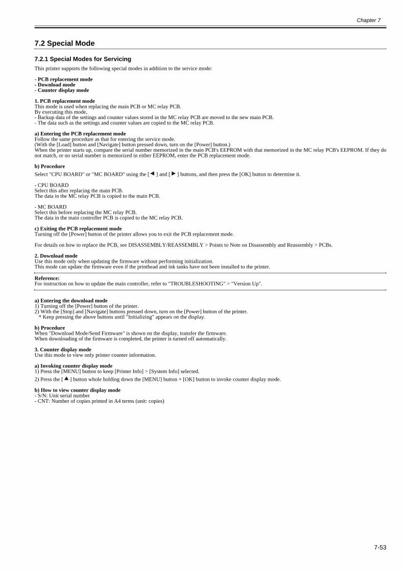
Chapter 7
7-53
7.2 Special Mode
7.2.1 Special Modes for Servicing0023-3043
This printer supports the following special modes in addition to the service mode:
- PCB replacement mode- Download mode- Counter display mode
1. PCB replacement modeThis mode is used when replacing the main PCB or MC relay PCB.By executing this mode,- Backup data of the settings and counter values stored in the MC relay PCB are moved to the new main PCB.- The data such as the settings and counter values are copied to the MC relay PCB.
a) Entering the PCB replacement modeFollow the same procedure as that for entering the service mode.(With the [Load] button and [Navigate] button pressed down, turn on the [Power] button.)When the printer starts up, compare the serial number memorized in the main PCB's EEPROM with that memorized in the MC relay PCB's EEPROM. If they donot match, or no serial number is memorized in either EEPROM, enter the PCB replacement mode.
b) ProcedureSelect "CPU BOARD" or "MC BOARD" using the [ ] and [ ] buttons, and then press the [OK] button to determine it.
- CPU BOARDSelect this after replacing the main PCB.The data in the MC relay PCB is copied to the main PCB.
- MC BOARDSelect this before replacing the MC relay PCB.The data in the main controller PCB is copied to the MC relay PCB.
c) Exiting the PCB replacement mode Turning off the [Power] button of the printer allows you to exit the PCB replacement mode.
For details on how to replace the PCB, see DISASSEMBLY/REASSEMBLY > Points to Note on Disassembly and Reassembly > PCBs.
2. Download modeUse this mode only when updating the firmware without performing initialization.This mode can update the firmware even if the printhead and ink tanks have not been installed to the printer.
Reference:For instruction on how to update the main controller, refer to "TROUBLESHOOTING" > "Version Up".
a) Entering the download mode1) Turning off the [Power] button of the printer.2) With the [Stop] and [Navigate] buttons pressed down, turn on the [Power] button of the printer. * Keep pressing the above buttons until "Initializing" appears on the display.
b) ProcedureWhen "Download Mode/Send Firmware" is shown on the display, transfer the firmware.When downloading of the firmware is completed, the printer is turned off automatically.
3. Counter display modeUse this mode to view only printer counter information.
a) Invoking counter display mode1) Press the [MENU] button to keep [Printer Info] > [System Info] selected.2) Press the [ ] button whole holding down the [MENU] button + [OK] button to invoke counter display mode.
b) How to view counter display mode- S/N: Unit serial number- CNT: Number of copies printed in A4 terms (unit: copies)

Chapter 7
7-54

Chapter 8 ERROR CODE


Contents
Contents
8.1 Outline............................................................................................................................................................................8-18.1.1 Outline.......................................................................................................................................................................................... 8-1
8.2 Warning Table................................................................................................................................................................8-28.2.1 Warnings ...................................................................................................................................................................................... 8-2
8.3 Error Table .....................................................................................................................................................................8-58.3.1 Errors............................................................................................................................................................................................ 8-5
8.4 Sevice Call Table .........................................................................................................................................................8-168.4.1 Service Call Errors ..................................................................................................................................................................... 8-16


Chapter 8
8-1
8.1 Outline
8.1.1 Outline0023-3204
The printer indicates errors using the display and LEDs.If an error occurs during printing, the printer status is also displayed on the status monitor of the printer driver. The following three types of errors are displayed on the display:
- WarningStatus where the print operation can be continued without remedying the cause of the problem. This can, however, adversely affect the printing results.
- ErrorStatus where the print operation is stopped, and the regular operation cannot be recovered until the cause of the problem is remedied.
- Service call errorWhen a service call error occurs, the error is not cleared and the error indication remains on the operation panel even if the printer is powered off and on again.(Occurrence of the service call error is indicated again at power-on.)This measure is taken to prevent user's recovery of the service call error and damages to the printer.Service call errors can be cleared, however, by starting up the printer in the service mode.
Note that some of the warnings, errors, and service call error described in the following tables may not appear in this printer.In addition, the message that appears on the screen may not be the same as what is described in the table.
The first 4 digits of Warning and Error code show the following description.
The first 2 digits of code Description01xxxxxx-xxx Warning03xxxxxx-xxx Error
The next 2 digits of code Descriptionxx01xxxx-xxxx Jam-relatedxx03xxxx-xxxx Cover-relatedxx06xxxx-xxxx Media-relatedxx13xxxx-xxxx Controller-relatedxx1Axxxx-xxxx HDD-relatedxx32xxxx-xxxx Media-relatedxx34xxxx-xxxx PDL-relatedxx80xxxx-xxxx Printhead-relatedxx81xxxx-xxxx Inktank-relatedxx83xxxx-xxxx Inktank-relatedxx84xxxx-xxxx Maintenance cartridge-relatedxx86xxxx-xxxx Print-relatedxx87xxxx-xxxx Cutter-relatedxx89xxxx-xxxx Media take-up unit-relatedxx90xxxx-xxxx Version up-related

Chapter 8
8-2
8.2 Warning Table
8.2.1 Warnings0024-9330
*: Codes represent the numbers that are displayed in DISPLAY of the service mode and that are recorded in PRINT INF. As to PRINT INF, the codes record thelast 4 digits. Messages that are not accompanied by a code indication are not logged.
Display message Code* Condition detected ActionCannot cut paper.Lift the release lever and reload the paper.
00000000-1011 Cannot cut perform force cutting because paper is too short.
Reload new paper.
Paper Mismatch. 01061000-1021 Paper type mismatch Match the paper type in printer driver and the one specified in printer panel.
Papr Size Mismatch 01063000-1022 Paper size mismatch Match the paper size in printer driver and the one specified in printer panel.
MediaType Mismatch 01063000-1023 Paper size/type mismatch Match the paper type/size in printer driver and the ones specified in printer panel.
PaperWidth Mismatch 01063000-1054 Roll media width mismatch
The occurrence conditions of roll paper width mismatch have been met with "Warning" set in [Detect Mismatch] in the menu settings.
The warning is cleared when the print job is completed or cancelled.
Mail box nearly full.Delete unwanted data
011A1001-2901 The free hard disk space left for Personal Boxes in the printer's hard disk does not have more than 1 GB, combined.
Delete unneeded jobs stored in Personal Boxes.
Maximum jobs stored.Delete unwanted data.
011A1006-2907 Saved jobs exceed the Personal Box capacity.
Press the stop button to cancel the print job.Delete print jobs from the queue.Delete unneeded jobs stored on the hard disk.
The paper is too small. 013200D2-1051 Size clip error Check the media size check.Change the media size.
GL2:W0501The memory is full.
01340501-1040 Memory full (HP-GL/2) Check if there is the non-image area of the print.Verify the transmitted data before reprinting.
GL2:W0502The parameter is out ofrange.
01340502-1041 Invalid parameter (HP-GL/2) Check if there is the non-image area of the print.Verify the transmitted data before reprinting.
GL2:W0504This command is notsupported.
01340504-1043 Invalid command (HP-GL/2) Check if there is the non-image area of the print.Verify the transmitted data before reprinting.
GL2:W0903The memory is full.
01340903-1047 Overflow of replot buffer (HP-GL/2) Check if there is the non-image area of the print.Verify the transmitted data before reprinting.
GL2:W0904The memory is full.
01340904-1048 Overflow of Polygon buffer (HP-GL/2) Check if there is the non-image area of the print.Verify the transmitted data before reprinting.
GARO W1221 01341221-1030 GARO (image mode) : Unknown command
Verify the transmitted data before reprinting.
GARO W1222 01341222-1031 GARO (image mode) : Invalid parameter count (no parameters)
Check if there is the non-image area of the print.Verify the transmitted data before reprinting.
GARO W1223 01341223-1032 GARO (image mode) : Required parameter missing
Check if there is the non-image area of the print.Verify the transmitted data before reprinting.
GARO W1224 01341224-1033 GARO error Check if there is the non-image area of the print.Verify the transmitted data before reprinting.
GARO W1225 01341225-1034 GARO (image mode) : Other warning Check if there is the non-image area of the print.Verify the transmitted data before reprinting.
GARO W1226 01341226-103A GARO (image mode) : Image processing table error
Verify that there is no image missing in print result.Verify the transmitted data before reprinting.
GARO W1231 01341231-1035 GARO (setup) : Unknown command Check if there is the non-image area of the print.Verify the transmitted data before reprinting.
GARO W1232 01341232-1036 GARO (setup) : Invalid parameter count Check if there is the non-image area of the print.Verify the transmitted data before reprinting.
GARO W1233 01341233-1037 GARO (setup) : Required parameter missing
Check if there is the non-image area of the print.Verify the transmitted data before reprinting.
GARO W1234 01341234-1038 GARO (setup) : Data out of bounds Check if there is the non-image area of the print.Verify the transmitted data before reprinting.
GARO W1235 01341235-1039 GARO (setup) : Other warning Check if there is the non-image area of the print.Verify the transmitted data before reprinting.
Problem with Printhead.Chk printing results
01800500-1010 Number of non-discharging nozzles in printhead:Warning level
Clean the printhead.Renew the printhead.Identify the head management sensor unit.
Problem with Printhead RChk printing results
01800500-1012 Non-discharge occurred in printhead1 Clean the printhead.Renew the right printhead.
Problem with Printhead LChk printing results
01800500-1013 Non-discharge occurred in printhead2 Clean the printhead.Renew the left printhead.
Ink Level: Check 01810101-1001 Y ink tank near-empty Renew the ink tank.No ink tank loaded.Check ink tank.
01810101-1411 Y ink tank removal Install the Y ink tank.
Ink Level: Check 01810102-1002 M ink tank near-empty Renew the ink tank.No ink tank loaded.Check ink tank.
01810102-1412 M ink tank removal Install the M ink tank.

Chapter 8
8-3
Ink Level: Check 01810103-1003 C ink tank near-empty Renew the ink tank.No ink tank loaded.Check ink tank.
01810103-1413 C ink tank removal Install the C ink tank.
Ink Level: Check 01810104-1000 BK ink tank near-empty Renew the ink tank.Ink Level: Check 01810104-1004 PM ink tank near-empty Renew the ink tank.No ink tank loaded.Check ink tank.
01810104-1410 BK ink tank removal Install the BK ink tank.
No ink tank loaded.Check ink tank.
01810104-1414 PM ink tank removal Install the PM ink tank.
Ink Level: Check 01810105-1005 PC ink near-empty Renew the ink tank.No ink tank loaded.Check ink tank.
01810105-1415 PC ink tank removal Install the PC ink tank.
Ink Level: Check 01810106-1006 MBK ink tank near-empty Renew the ink tank.No ink tank loaded.Check ink tank.
01810106-1416 MBK ink tank removal Install the MBK ink tank.
Ink Level: Check 01810107-1007 MBK2 ink tank near-empty Renew the ink tank.Not much ink is left. Prepare to replace the ink.
01810107-100A R ink tank near-empty Renew the R ink tank.
No ink tank loaded.Check ink tank.
01810107-1417 MBK ink tank removal Install the MBK ink tank.
No ink tank loaded.Check ink tank.
01810107-141A No R ink tank warning Install the ink tank.
Ink Level: Check 01810108-1008 GY ink near-empty Renew the ink tank.Not much ink is left. Prepareto replace the ink.
01810108-100C G ink tank near-empty Renew the G ink tank.
No ink tank loaded.Check ink tank.
01810108-1418 GY ink tank removal Install the GY ink tank.
No ink tank loaded.Check ink tank.
01810108-141C No G ink tank warning Install the ink tank.
Ink Level: Check 01810109-1009 PGY ink near-empty Renew the ink tank.Not much ink is left. Prepareto replace the ink.
01810109-100B B ink tank near-empty Renew the B ink tank.
No ink tank loaded.Check ink tank.
01810109-1419 PGY ink tank removal Install the PGY ink tank.
No ink tank loaded.Check ink tank.
01810109-141B No B ink tank warning Install the ink tank.
Ink tank is empty.Replace the ink tank.
01810301-1401 Y ink tank empty Renew the Y ink tank.
Ink tank is empty.Replace the ink tank.
01810302-1402 M ink tank empty Renew the M ink tank.
Ink tank is empty.Replace the ink tank.
01810303-1403 C ink tank empty Renew the C ink tank.
Ink tank is empty.Replace the ink tank.
01810304-1400 BK ink tank empty Renew the BK ink tank.
Ink tank is empty.Replace the ink tank.
01810304-1404 PM ink tank empty Renew the PM ink tank.
Ink tank is empty.Replace the ink tank.
01810305-1405 PC ink tank empty Renew the PC ink tank.
Ink tank is empty.Replace the ink tank.
01810306-1406 MBK ink tank empty Renew the MBK ink tank.
Ink tank is empty.Replace the ink tank.
01810307-1407 MBK2 ink tank empty Renew the MBK2 ink tank.
Ink tank is empty.Replace the ink tank.
01810307-140A R ink tank empty Renew the R ink tank.
Ink tank is empty.Replace the ink tank.
01810308-1408 GY ink tank empty Renew the GY ink tank.
Ink tank is empty.Replace the ink tank.
01810308-140C G ink tank empty Renew the G ink tank.
Ink tank is empty.Replace the ink tank.
01810309-1409 PGY ink tank empty Renew the PGY ink tank.
Ink tank is empty.Replace the ink tank.
01810309-140B B ink tank empty Renew the B ink tank.
Prepare for maint cart replacement. 01841001-281A Maintenance cartridge near-full Replace the maintenance cartridge.This type of paper is not compatible with HP-GL/2.
01860006-1015 Non-support paper of HP-GL/2 Exchange for the compatible paper to HP-GL/2.
Borderless printing not possible.Check supported paper.
01861001-1052 Borderless printing disabled (unsupported size)
The occurrence conditions of borderless printing not possible error (unsupported size) have been met with "Warning" set in [Detect Mismatch] in the menu settings.
The warning is cleared when the print job is completed or cancelled.
Display message Code* Condition detected Action

Chapter 8
8-4
Paper position not suitable for borderless printing.
01861001-1053 Borderless printing disabled (physical)
The occurrence conditions of borderless printing not possible error (physical) have been met with "Warning" set in [Detect Mismatch] in the menu settings.
The warning is cleared when the print job is completed or cancelled.
Mail box full.Now printing without saving data.
01861003-2902 100 jobs are stored in the Personal Box. Delete unneeded jobs stored in Personal Boxes.
Before borderless printing,move the blue platen switch.
01861004-1049 The platen shutter is closed at the borderless printing.
Open the corresponding platen shutter.Check the platen and multi sensor and surrounding parts.Replace the multi sensor.
Blue platen switch is dirty.Please clean the switch.
01861004-1050 Platen shutter cleaning warning Clean the platen shutter.
Before borderless printing,move the blue platen switch.
01861006-1055 Platen shutter No.1 open warning Open the corresponding platen shutter.Check the platen and multi sensor and surrounding parts.Replace the multi sensor.
Before borderless printing,move the blue platen switch.
01861007-1056 Platen shutter No.2 open warning Open the corresponding platen shutter.Check the platen and multi sensor and surrounding parts.Replace the multi sensor.
Before borderless printing,move the blue platen switch.
01861008-1057 Platen shutter No.3 open warning Open the corresponding platen shutter.Check the platen and multi sensor and surrounding parts.Replace the multi sensor.
Before borderless printing,move the blue platen switch.
01861009-1058 Platen shutter No.4 open warning Open the corresponding platen shutter.Check the platen and multi sensor and surrounding parts.Replace the multi sensor.
Before borderless printing,move the blue platen switch.
0186100A-1059 Platen shutter No.5 open warning Open the corresponding platen shutter.Check the platen and multi sensor and surrounding parts.Replace the multi sensor.
Before borderless printing,move the blue platen switch.
0186100B-105A Platen shutter No.6 open warning Open the corresponding platen shutter.Check the platen and multi sensor and surrounding parts.Replace the multi sensor.
Before borderless printing,move the blue platen switch.
0186100C-105B Platen shutter No.7 open warning Open the corresponding platen shutter.Check the platen and multi sensor and surrounding parts.Replace the multi sensor.
Before borderless printing,move the blue platen switch.
0186100D-105C Platen shutter No.8 open warning Open the corresponding platen shutter.Check the platen and multi sensor and surrounding parts.Replace the multi sensor.
Before borderless printing,move the blue platen switch.
0186100E-105D Platen shutter No.9 open warning Open the corresponding platen shutter.Check the platen and multi sensor and surrounding parts.Replace the multi sensor.
Before borderless printing,move the blue platen switch.
0186100F-105E Platen shutter No.10 open warning Open the corresponding platen shutter.Check the platen and multi sensor and surrounding parts.Replace the multi sensor.
Before borderless printing,move the blue platen switch.
01861010-105F Platen shutter No.11 open warning Open the corresponding platen shutter.Check the platen and multi sensor and surrounding parts.Replace the multi sensor.
Before borderless printing,move the blue platen switch.
01861011-1060 Platen shutter No.12 open warning Open the corresponding platen shutter.Check the platen and multi sensor and surrounding parts.Replace the multi sensor.
Before borderless printing,move the blue platen switch.
01861012-1061 Platen shutter No.13 open warning Open the corresponding platen shutter.Check the platen and multi sensor and surrounding parts.Replace the multi sensor.
Before borderless printing,move the blue platen switch.
01861013-1062 Platen shutter No.14 open warning Open the corresponding platen shutter.Check the platen and multi sensor and surrounding parts.Replace the multi sensor.
Parts replacement time has passed.Call for service.
Parts counter W2 level After checking the parts counter in service mode, replace any part whose counter is nearing the error value.
End of paper feed.Cannot feed paper more.
Forced feed limit Check the remaining quantity of roll media.
Prepare for parts replacement.Call for service.
Parts counter W1 level Check the parts counter in service mode.
Display message Code* Condition detected Action

Chapter 8
8-5
8.3 Error Table
8.3.1 Errors0024-9331
*: Codes represent the numbers that are displayed in DISPLAY of the service mode and that are recorded in PRINT INF. As to PRINT INF, the codes record thelast 4 digits.
Display message Code* Condition detected ActionPaper size not detected.Reload paper.
03010000-200A Unable to detect the paper width (Paper loaded at an improper position)
Reload the paper.
Paper size not detected.Lift the release lever and reload the paper.
03010000-200C Unable to detect the leading end of paper Check the leading end of paper. Reload the paper.
Leading edge detection error.Lift the release lever and align leading edge with orange line.
03010000-200D Unable to detect the trailing end of cut sheet
Check the sheet length. Check to see if paper has not jammed.
This paper cannot be used.Check supported paper sizes.
03010000-200E Undersized paper (cut sheets/roll media) Replace with larger-sized paper.
This paper cannot be used.Check supported paper sizes.
03010000-200F Oversized paper (cut sheets/roll media) Replace with smaller-sized paper.
Paper jam.Manually rewind roll all the way.
03010000-2016 Cut sheet feed failure Check or replace a cut sheet.
Paper size not detected.Lift the release lever and reload the paper.
03010000-2017 Paper (right) edge detection error Check the right edge of paper.Check the paper type.
Paper size not detected.Lift the release lever and reload the paper.
03010000-2018 Paper (left) edge detection error Check the left edge of paper.Check the paper type.
! Paper not aligned with right guide.
(Change to the following message)
! Push the release lever back, then reload the paper.
03010000-201A Paper (right) edge detection error (cut sheet pick-up)
Set or replace the media.
! Paper not aligned with right guide.
(Change to the following message)
! Push the release lever back, then reload the paper.
03010000-201B Paper (right) edge detection error (roll media pick-up)
Set or replace the media.
Paper jam.
Lift the release lever and remove the paper.
03010000-201C Paper (right) edge detection error (cut sheet printing)
Set or replace the media.
Paper jam.
Lift the release lever and remove the paper.
03010000-201D Paper (left) edge detection error (roll media printing)
Set or replace the media.
Cannot print as specified.Replace paper with A4/LTR (vertical) or larger
03010000-2E1F Undersized paper loaded for internal printing (A3 or larger)
Replace with A3/11"x17" or any larger-sized paper A3/11"x17"
Cannot feed paper.Remove paper and press Load/Eject.
03010000-2E25 Paper jam while feeding/ejecting/printing Remove the paper jam and reload the paper.
Cannot feed paper.Lift the release lever and reload paper.orPaper jam.Manually rewind roll all the way.
03010000-2E27 Paper jam during feeding/printing/ejection Reload the paper.
Paper jam.Manually rewind roll all the way and press OK.
03010000-2E3A Media load failure Check the pick-up unit and roll media.Check to see if paper has not jammed.
Paper jam.Manually rewind roll all the way and press OK.
03010000-2E3B Media load failure (lower roll) Check the pick-up unit and roll media.Check to see if paper has not jammed.
! Roll jamLift the release lever.
03010000-2E3C When operating with cut sheet, paper jam is detected.
Check the paper path, and check if paper is stuck inside the machine.
! Roll 1 (upper) jamLift the release lever.
03010000-2E3D When operating with upper roll paper, paper jam is detected.
Check the paper path, and check if paper is stuck inside the machine.
! Roll 2 (lower) jamLift the release lever.
03010000-2E3E When operating with lower roll paper, paper jam is detected.
Check the paper path, and check if paper is stuck inside the machine.
! Roll jamLift the release lever.
03010000-2E3F When operating with roll paper, paper jam is detected.
Check the paper path, and check if paper is stuck inside the machine.
Error in cutter position. 03010000-2E47 Cutter position error Check the cutter unit and surrounding part.Hardware error.03130031-2E29Turn off printer, wait, then turn on again.
03010000-2F29 Feed motor timeout (Roll media) Check the roll feed unit.Check roll media.Check to see if paper has not jammed in the printer.
Use another paper.Press Online to clear the error.
03010000-2F33 Unadjustable because of transparent media Replace with adjustable media.
Paper loaded askew.Lift the release lever.
03016000-2010 Skew Correct the skew in the paper and reload it.

Chapter 8
8-6
Ink tank cover is open.Turn off printer, wait a while, and turn it on again.
03031000-2E10 Ink tank cover abnormally open Close the ink tank cover and turn on the printer again.
Carriage Cover is open.
Turn off printer, wait a while, and turn it on again.
03031000-2E11 Printhead cover open Close the carriage cover and turn off the printer, and turn it on again.
Rel lever is in wrong position.
Turn off printer, wait, then turn on again.
03031000-2E12 Release lever open Close the release lever and turn off the printer, and turn it on again.
Rel lever is in wrong position.Turn off printer, wait, then turn on again.
03031000-2F21 Pinch roller open error Check the pinch roller unit and surrounding part.
Top cover is open.Turn off printer, wait a while, and turn it on again.
03031000-2F38 Top cover abnormally open Close the top cover and turn on the printer again.
! Unable to detect ink level correctly. 03031101-25B7 With ink tank cover open, ink has diminished below the pin check level.
During printing with ink tank cover open, the ink has diminished below the pin check level.*Under study as a part of stop-less supply system. This error is intended for preventing the ink tank to be installed in other model (iPF710) using the same ink tank by the hardware configuration that disables writing to ink tank EEPROM while ink tank cover is open.
By closing the ink tank cover, this warning is cleared.If the pin check tank is removed in this condition, the error changes to the pin check tank removal error. Or, if printing is continued in this condition, and the subtank corresponding to the pin check tank is detected empty, the error changes to the subtank corresponding to pin check tank empty error.
! Paper mismatchMake sure media type and paper size match for the adjustment print.
03060000-2E20 Paper type mismatch at adjustment Choose the same paper type as the first page and perform adjustment printing.
Sheet printing is selected.Press Load/Eject and load sheets.
03060100-2E02 After starting to print sheet, no manual feeding paper has been detected.
Load cut sheet in manual feeding slot.
Sheet printing is selected.Press Load/Eject and load sheets.
03060100-2E04 No front manual feed paper Load cut sheet in the front manual feed paper slot.
Sheet printing is selected.Press Load/Eject and load sheets.
03060100-2E05 After starting to print sheet, no manual feeding paper has been detected.
Load cut sheet in manual feeding slot.
Sheet printing is selected.Press Load/Eject and load sheets.
03060200-2E03 No cassette paper Load cut sheet in the cassette.
Cassette printing is selected.
Press Load/Eject and remove manually
03060200-2E0B After manual feed cut sheet had been loaded, data with cassette specification was received.
Load cut sheet in the cassette.
Roll printing is selected.Press Load/Eject and load a roll.
03060A00-2E00 Data with a roll media specification has been received but no roll media are loaded.
Load roll media.
Roll printing is selected.Press Load/Eject and load a roll.
03060A00-2E01 No roll paper at internal printing Load roll media.
PaprWidth Mismatch Plain Paper ISO A3
Online=PrintStop=Stop Printing
03060A00-2E08 Paper width mismatch Check the paper width and print.
No Roll Feed Unit.Turn printer off and install roll feed unit.
03060A00-2E0E Roll media unit not installed. Install the roll media unit.
The roll is empty.Lift the release lever and replace the roll.
03060A00-2E1B Roll media end Renew the supply of roll media.
Roll feed unit errTurn off printer and check roll feed unit
03060A00-2E24 Roll cam sensor error Check the roll paper unit.
Roll Paper Plain Paper ISO A3
Load Roll PaperStop Printing
03060A00-2E33 Roll media is not loaded when receiving the printing job.Roll paper is not loaded when a job with roll paper specification has been received.
(1) Choose [Load Roll Paper] and load paper according to the panel guidance.(2) Choose [Stop Printing] or press the Stop button to stop printing.(3) Lift the release lever, and load paper.
! Roll2 (Lower) printing is selected.
Press Load/Eject and load a roll.
03060A00-2E34 Roll paper is not loaded. (lower roll) (1) Choose [Load Roll Paper] and load paper according to the panel guidance.(2) Choose [Stop Printing] or press the Stop button to stop printing.(3) Lift the release lever, and load paper.
Roll printing is selected.Press Load/Eject and load a roll.
03060A00-2E35 Roll media is not loaded for internal printing.
Reload the roll media.
! Roll 1 (Upper) printing is selected.
Press Load/Eject and load a roll.
03060A00-2E37 Roll paper is not loaded. (upper roll) (1) Choose [Load Roll Paper] and load paper according to the panel guidance.(2) Choose [Stop Printing] or press the Stop button to stop printing.(3) Lift the release lever, and load paper.
! Roll printing is selected.Press Load/Eject and load a roll.
03060B00-2E36 Roll media is not loaded for internal printing. (lower roll)
Load the roll media.
! The roll is empty.
Lift the release lever and replace the roll.
03060B00-2E39 Lower roll end Load roll paper in lower roll.
Display message Code* Condition detected Action

Chapter 8
8-7
This type of paper is not compatible with HP-GL/2.Online: PrintStop: Stop PrintingLoad/Eject: Change Paper
03061000-2E15 Non-support media of HP-GL/2 Exchange for the compatible paper to HP-GL/2 before reprinting.
Wrong paper size.Check paper size setting in driver.
Online: PrintStop: Stop Printing
03063000-2E08 Paper width mismatch Check the paper width and print.
! Hardware error.03130000-2E21Turn off printer, wait, then turn on again.
03130000-2E21 IEEE1394 port error Restart or replace the IEEE1394 board.
Hardware error.03130031-260ETurn off printer, wait, then turn on again.
03130031-260E Gap detection error Check the carriage unit and surrounding parts.Replace the main controller PCB.
Hardware error.03130031-260FTurn off printer, wait, then turn on again.
03130031-260F Gap reference surface error Replace the multi sensor reference.
Hardware error.03130031-2618Turn off printer, wait, then turn on again.
03130031-2618 VH voltage error Check the power supply unit.
Hardware error.03130031-290ATurn off printer, wait, then turn on again.
03130031-290A Hard disk disconnection error Check the connection status of HDD.
Hardware error.03130031-2E23Turn off printer, wait, then turn on again.
03130031-2E23 Cutter unit failure Check the cutter unit and sensor.
Hardware error.03130031-2E13Turn off printer, wait, then turn on again.
03130031-2F13 A/D converter external trigger output stop detection hardware error 1
Check the carriage unit and surrounding parts.
Hardware error.03130031-2E14Turn off printer, wait, then turn on again.
03130031-2F14 Writing to the ASIC register disabled Replace the main controller PCB.
Hardware error.03130031-2E16Turn off printer, wait, then turn on again.
03130031-2F16 Mist fan rotation error Check the mist fan.
Hardware error.03130031-2E17Turn off printer, wait, then turn on again.
03130031-2F17 Platen suction fan lock detection error Check the platen suction fan.
Hardware error.03130031-2E1FTurn off printer, wait, then turn on again.
03130031-2F1F Pump cam sensor error Check the purge unit.
Hardware error.03130031-2E20Turn off printer, wait, then turn on again.
03130031-2F20 Purge motor cam position error Check the purge unit.
Hardware error.03130031-2E22Turn off printer, wait, then turn on again.
03130031-2F22 Pump move timeout Check the purge unit.
Hardware error.03130031-2E23Turn off printer, wait, then turn on again.
03130031-2F23 Purge motor errorPump inoperable
Check the purge unit.
Hardware error.03130031-2E25Turn off printer, wait, then turn on again.
03130031-2F25 Unable to detect the carriage motor home position
Check the carriage unit.Check the linear encoder for smears.
Hardware error.03130031-2E26Turn off printer, wait, then turn on again.
03130031-2F26 Carriage inoperable Check the carriage unit and surrounding parts.
Hardware error.03130031-2E27Turn off printer, wait, then turn on again.
03130031-2F27 Carriage move timeout Check the carriage unit and surrounding parts.
Hardware error.03130031-2E2ATurn off printer, wait, then turn on again.
03130031-2F2A Unable to detect the feed roller home position
Check the feed roller encoder and surrounding part.Check to see if paper has not jammed.
Hardware error.03130031-2F2BTurn off printer, wait, then turn on again.
03130031-2F2B LF operation failure Check to see if paper has not jammed.Check the feed motor and feed roller.
Hardware error.03130031-2E2ETurn off printer, wait, then turn on again.
03130031-2F2E Roll travel timeout Check the roll feed unit.
Hardware error.03130031-2F32Turn off printer, wait, then turn on again.
03130031-2F32 Multi sensor error Check the environment for interferences from outside light.
Excessive temperature or humidity. 03130031-2F35 Calibration environment error Check if the temperature or humidity is within the scope of calibration operation.
Hardware error.03130031-2F3ATurn off printer, wait, then turn on again.
03130031-2F3A Valve motor error Check the ink supply unit.
Hardware error.03130031-2F3BTurn off printer, wait, then turn on again.
03130031-2F3B CS communication error Remove the ink tanks and then reload them.Replace the ink tank.
Display message Code* Condition detected Action
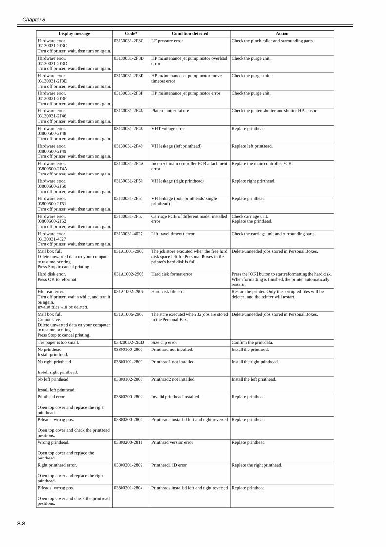
Chapter 8
8-8
Hardware error.03130031-2F3CTurn off printer, wait, then turn on again.
03130031-2F3C LF pressure error Check the pinch roller and surrounding parts.
Hardware error.03130031-2F3DTurn off printer, wait, then turn on again.
03130031-2F3D HP maintenance jet pump motor overload error
Check the purge unit.
Hardware error.03130031-2F3ETurn off printer, wait, then turn on again.
03130031-2F3E HP maintenance jet pump motor move timeout error
Check the purge unit.
Hardware error.03130031-2F3FTurn off printer, wait, then turn on again.
03130031-2F3F HP maintenance jet pump motor error Check the purge unit.
Hardware error.03130031-2F46Turn off printer, wait, then turn on again.
03130031-2F46 Platen shutter failure Check the platen shutter and shutter HP sensor.
Hardware error.03800500-2F48Turn off printer, wait, then turn on again.
03130031-2F48 VHT voltage error Replace printhead.
Hardware error.03800500-2F49Turn off printer, wait, then turn on again.
03130031-2F49 VH leakage (left printhead) Replace left printhead.
Hardware error.03800500-2F4ATurn off printer, wait, then turn on again.
03130031-2F4A Incorrect main controller PCB attachment error
Replace the main controller PCB.
Hardware error.03800500-2F50Turn off printer, wait, then turn on again.
03130031-2F50 VH leakage (right printhead) Replace right printhead.
Hardware error.03800500-2F51Turn off printer, wait, then turn on again.
03130031-2F51 VH leakage (both printheads/ single printhead)
Replace printhead.
Hardware error.03800500-2F52Turn off printer, wait, then turn on again.
03130031-2F52 Carriage PCB of different model installed error
Check carriage unit.Replace the printhead.
Hardware error.03130031-4027Turn off printer, wait, then turn on again.
03130031-4027 Lift travel timeout error Check the carriage unit and surrounding parts.
Mail box full.Delete unwanted data on your computer to resume printing.Press Stop to cancel printing.
031A1001-2905 The job store executed when the free hard disk space left for Personal Boxes in the printer's hard disk is full.
Delete unneeded jobs stored in Personal Boxes.
Hard disk error.Press OK to reformat
031A1002-2908 Hard disk format error Press the [OK] button to start reformatting the hard disk. When formatting is finished, the printer automatically restarts.
File read error.Turn off printer, wait a while, and turn it on again.Invalid files will be deleted.
031A1002-2909 Hard disk file error Restart the printer. Only the corrupted files will be deleted, and the printer will restart.
Mail box full.Cannot save.Delete unwanted data on your computer to resume printing.Press Stop to cancel printing.
031A1006-2906 The store executed when 32 jobs are stored in the Personal Box.
Delete unneeded jobs stored in Personal Boxes.
The paper is too small. 033200D2-2E30 Size clip error Confirm the print data.No printheadInstall printhead.
03800100-2800 Printhead not installed. Install the printhead.
No right printhead
Install right printhead.
03800101-2800 Printhead1 not installed. Install the right printhead.
No left printhead
Install left printhead.
03800102-2808 Printhead2 not installed. Install the left printhead.
Printhead error
Open top cover and replace the right printhead.
03800200-2802 Invalid printhead installed. Replace printhead.
PHeads: wrong pos.
Open top cover and check the printhead positions.
03800200-2804 Printheads installed left and right reversed Replace printhead.
Wrong printhead.
Open top cover and replace the printhead.
03800200-2811 Printhead version error Replace printhead.
Right printhead error.
Open top cover and replace the right printhead.
03800201-2802 Printhead1 ID error Replace the right printhead.
PHeads: wrong pos.
Open top cover and check the printhead positions.
03800201-2804 Printheads installed left and right reversed Replace printhead.
Display message Code* Condition detected Action

Chapter 8
8-9
Right printhead error.
Open top cover and replace the right printhead.
03800201-2812 Printhead1 wrong version error Replace the right printhead.
PHeads: wrong pos.
Open top cover and check the printhead positions.
03800202-2807 Printheads installed left and right reversed Check the installation position of printhead.Replace printhead.
Left printhead error.
Open top cover and replace the left printhead.
03800202-280A Printhead2 ID error Replace the left printhead.
Left printhead error.
Open top cover and replace the left printhead.
03800202-2813 Printhead2 wrong version error Replace the left printhead.
! Printhead L error.
Turn off printer, wait a while, then turn it on again.
03800202-282D Left printhead abnormal temperature detection error (during maintenance jet)
Turn off the printer, and then turn it on again and replace the left printhead.
! Left printhead error
Open top cover and replace the left printhead.
03800202-2830 Printhead2 temperature rise error Replace the left printhead.
Printhead error
Open top cover and replace the right printhead.
03800300-2801 Printhead DI compensation failure Replace printhead.
Right printhead error.
Open top cover and replace the right printhead.
03800301-2801 Printhead1 DI compensation failure Replace the right printhead.
Left printhead error.
Open top cover and replace the left printhead.
03800302-2809 Printhead2 DI compensation failure Replace the left printhead.
Printhead error
Open top cover and replace the right printhead.
03800400-2803 Printhead EEPROM error Replace printhead.
Right printhead error.
Open top cover and replace the right printhead.
03800401-2803 Printhead1EEPROM error Replace the right printhead.
Left printhead error.
Open top cover and replace the left printhead.
03800402-280B Printhead2 EEPROM error Replace the left printhead.
Execute printhead cleaning.If this message is still displayed, replace the printhead.
03800500-280C Printhead found to have many non-discharging nozzles during a non-discharging inspection (printing paused)
Clean the printhead.Identify the nozzles in a nozzle check pattern.Replace the printhead.
Execute printhead cleaning.
If this message is still displayed, replace the printhead.Printing stopped.
03800500-2827 Printhead found to have many non-discharging nozzles during a non-discharging inspection (printing stopped)
Clean the printhead. Identify the nozzles in a nozzle check pattern.Replace the printhead.
Hardware error.03800500-2F2FTurn off printer, wait, then turn on again.
03800500-2F2F The non-discharge of the EVEN or ODD line (640-nozzles) is detected the 320-nozzles or more.
Check the head management sensor and surrounding parts.Check that the printhead is installed correctly.Replace the head management sensor.Replace the printhead.
Hardware error.03800500-2F30Turn off printer, wait, then turn on again.
03800500-2F30 Detectable area failure (when adjusting the position of non-discharging nozzle)The gap of detection position of nozzle both ends is big.
Check the ink tube unit and surrounding parts.Check the purge unit and surrounding parts.Check the head management sensor and surrounding parts.Check the flexible cable unit and surrounding parts.Check that the printhead is installed correctly.Replace the main controller PCB.Replace the printhead.Replace the carriage unit.
Hardware error.03800500-2F31Turn off printer, wait, then turn on again.
03800500-2F31 Non-discharge detection optical axis error Check the head management sensor.Replace the head management sensor.Replace the printhead.
Hardware error.03800500-2F40Turn off printer, wait, then turn on again.
03800500-2F40 The non-discharge of all colors and chips (A/B, EVEN/ODD) and nozzles is detected.
Check the ink tube unit and surrounding parts.Check the purge unit and surrounding parts.Check the head management sensor and surrounding parts.Check the flexible cable unit and surrounding parts.Check that the printhead is installed correctly.Replace the head management sensor.Replace the main controller PCB.Replace the printhead.Replace the carriage unit.
Display message Code* Condition detected Action

Chapter 8
8-10
Hardware error.03800500-2F41Turn off printer, wait, then turn on again.
03800500-2F41 About all chips and nozzles of one color, the non-discharge is detected.
Check the head management sensor andsurrounding parts.Check the flexible cable unit and surrounding parts.Check that the printhead is installed correctly.Replace the main controller PCB.Replace the printhead.Replace the carriage unit.
Hardware error.03800500-2F42Turn off printer, wait, then turn on again.
03800500-2F42 About single line (A or B) and all nozzles (1280-nozzles) of one color, the non-discharge is detected.
Check the head management sensor and surrounding parts.Check the flexible cable unit and surrounding parts.Check that the printhead is installed correctly.Replace the main controller PCB.Replace the printhead.Replace the carriage unit.
Hardware error.03800500-2F43Turn off printer, wait, then turn on again.
03800500-2F43 About single chip (A or B, EVEN or ODD) and all nozzles (640-nozzles) of one color, the non-discharge is detected.
Check the head management sensor and surrounding parts.Check the flexible cable unit and surrounding parts.Check that the printhead is installed correctly.Replace the main controller PCB.Replace the printhead.Replace the carriage unit.
Hardware error.03800500-2F44Turn off printer, wait, then turn on again.
03800500-2F44 The non-discharge of the EVEN or ODD line (640-nozzles) is detected.
Check the head management sensor and surrounding parts.Check that the printhead is installed correctly.Replace the main controller PCB.Replace the printhead.Replace the carriage unit.
Hardware error.03800500-2F47Turn off printer, wait, then turn on again.
03800500-2F47 Head management sensor failureThe APCCHK signal of head management sensor is out of range.
Check the head management sensor and surrounding parts.Replace the head management sensor.Replace the main controller PCB.
Clean right P Head
Press Online to clear error.
03800501-280D Printhead1 non-discharge detection error Clean the printhead.Identify the nozzles in a nozzle check pattern.Replace the right printhead.
Execute printhead cleaning.
If this message is still displayed, replace the printhead.Printing stopped.
03800501-2828 Printhead1 non-discharge error (printhead replacement)
Execute printhead cleaning.Check nozzles with nozzle check pattern.Replace the printhead.
Clean left P Head
Press Online to clear error.
03800502-280E Printhead2 non-discharge detection error Clean the printhead.Identify the nozzles in a nozzle check pattern.Replace the left printhead.
Execute printhead cleaning.
If this message is still displayed, replace the printhead.Printing stopped.
03800502-2829 Printhead2 non-discharge error (printhead replacement)
Execute printhead cleaning.Check nozzles with nozzle check pattern.Replace the printhead.
Ink tank is empty.Press OK and replace ink tank.
03810101-2501 Y ink tank empty Renew the Y ink tank.
Remaining level of the ink cannot be correctly detected.Check ink tank.
03810101-2511 Unidentified status of Y ink tank (refill ink tank detection)
Invalidate the ink remaining detection function or replace the ink tank.
Ink tank is empty.Press OK and replace ink tank.
03810102-2502 M ink tank empty Renew the M ink tank.
Remaining level of the ink cannot be correctly detected.Check ink tank.
03810102-2512 Unidentified status of M ink tank (refill ink tank detection)
Invalidate the ink remaining detection function or replace the ink tank.
Ink tank is empty.Press OK and replace ink tank.
03810103-2503 C ink tank empty Renew the C ink tank.
Remaining level of the ink cannot be correctly detected.Check ink tank.
03810103-2513 Unidentified status of C ink tank (refill ink tank detection)
Invalidate the ink remaining detection function or replace the ink tank.
Ink tank is empty.Press OK and replace ink tank.
03810104-2500 BK ink tank empty Renew the BK ink tank.
Remaining level of the ink cannot be correctly detected.Check ink tank.
03810104-2510 Unidentified status of BK ink tank (refill ink tank detection)
Invalidate the ink remaining detection function or replace the ink tank.
Ink tank is empty.Press OK and replace ink tank.
03810105-2508 GY ink tank empty Renew the GY ink tank.
Remaining level of the ink cannot be correctly detected.Check ink tank.
03810105-2518 Unidentified status of GY ink tank (refill ink tank detection)
Invalidate the ink remaining detection function or replace the ink tank.
Ink tank is empty.Press OK and replace ink tank.
03810106-2506 MBK ink tank empty Renew the MBK ink tank.
Ink tank is empty.Press OK and replace ink tank.
03810106-2507 MBK2 ink tank empty Renew the MBK ink tank.
Remaining level of the ink cannot be correctly detected.Check ink tank.
03810106-2516 Unidentified status of MBK ink tank (refill ink tank detection)
Invalidate the ink remaining detection function or replace the ink tank.
Remaining level of the ink cannot be correctly detected.Check ink tank.
03810106-2517 Unidentified status of MBK2 ink tank (refill ink tank detection)
Invalidate the ink remaining detection function or replace the ink tank.
Display message Code* Condition detected Action

Chapter 8
8-11
Ink tank is empty.Press OK and replace ink tank.
03810107-250A R ink tank empty Renew the R ink tank.
Remaining level of the ink cannot be correctly detected.Check ink tank.
03810107-251A Unidentified status of R ink tank (refill ink tank detection)
Invalidate the ink remaining detection function or replace the ink tank.
Ink tank is empty.Press OK and replace ink tank.
03810108-250C G ink tank empty Renew the G ink tank.
Remaining level of the ink cannot be correctly detected.Check ink tank.
03810108-251C Unidentified status of G ink tank (refill ink tank detection)
Invalidate the ink remaining detection function or replace the ink tank.
Ink tank is empty.Press OK and replace ink tank.
03810109-250B B ink tank empty Renew the B ink tank.
Remaining level of the ink cannot be correctly detected.Check ink tank.
03810109-251B Unidentified status of B ink tank (refill ink tank detection)
Invalidate the ink remaining detection function or replace the ink tank.
Ink tank is empty.Press OK and replace ink tank.
03810112-2504 PM ink tank empty Renew the PM ink tank.
Remaining level of the ink cannot be correctly detected.Check ink tank.
03810112-2514 Unidentified status of PM ink tank (refill ink tank detection)
Invalidate the ink remaining detection function or replace the ink tank.
Ink tank is empty.Press OK and replace ink tank.
03810113-2505 PC ink tank empty Renew the PC ink tank.
Remaining level of the ink cannot be correctly detected.Check ink tank.
03810113-2515 Unidentified status of PC ink tank (refill ink tank detection)
Invalidate the ink remaining detection function or replace the ink tank.
Ink tank is empty.Press OK and replace ink tank.
03810115-2509 PGY ink tank empty Renew the PGY ink tank.
Remaining level of the ink cannot be correctly detected.Check ink tank.
03810115-2519 Unidentified status of PGY ink tank (refill ink tank detection)
Invalidate the ink remaining detection function or replace the ink tank.
Ink insufficient.Press OK and replace ink tank.
03810201-2581 Low on the Y ink tank (as during cleaning) Replace with a fully replenished Y ink tank.
Ink insufficient.Press OK and replace ink tank.
03810201-2591 Low on the Y ink tank (during pre-printing checks)
Replace with a fully replenished Y ink tank.
Ink insufficient.Press OK and replace ink tank.
03810202-2582 Low on the M ink tank (as during cleaning) Replace with a fully replenished M ink tank.
Ink insufficient.Press OK and replace ink tank.
03810202-2592 Low on the M ink tank (during pre-printing checks)
Replace with a fully replenished M ink tank.
Ink insufficient.Press OK and replace ink tank.
03810203-2583 Low on the C ink tank (as during cleaning) Replace with a fully replenished C ink tank.
Ink insufficient.Press OK and replace ink tank.
03810203-2593 Low on the C ink tank (during pre-printing checks)
Replace with a fully replenished C ink tank.
Ink insufficient.Press OK and replace ink tank.
03810204-2580 Low on the BK ink tank (as during cleaning)
Replace with a fully replenished BK ink tank.
Ink insufficient.Press OK and replace ink tank.
03810204-2590 Low on the BK ink tank (during pre-printing checks)
Replace with a fully replenished BK ink tank.
Ink insufficient.Press OK and replace ink tank.
03810205-2588 Low on the GY ink tank (as during cleaning)
Replace with a fully replenished GY ink tank.
Ink insufficient.Press OK and replace ink tank.
03810205-2598 Low on the GY ink tank (during pre-printing checks)
Replace with a fully replenished GY ink tank.
Ink insufficient.Press OK and replace ink tank.
03810206-2586 Low on the MBK ink tank (as during cleaning)
Replace with a fully replenished MBK ink tank.
Ink insufficient.Press OK and replace ink tank.
03810206-2587 Low on the MBK2 ink tank (as during cleaning)
Replace with a fully replenished MBK ink tank.
Ink insufficient.Press OK and replace ink tank.
03810206-2596 Low on the MBK ink tank (during pre-printing checks)
Replace with a fully replenished MBK ink tank.
Ink insufficient.Press OK and replace ink tank.
03810206-2597 Low on the MBK2 ink tank (during pre-printing checks)
Replace with a fully replenished MBK ink tank.
Ink insufficient.Press OK and replace ink tank.
03810207-258A Low on the R ink tank (as during cleaning) Replace with a fully replenished R ink tank.
Ink insufficient.Press OK and replace ink tank.
03810207-259A Low on the R ink tank (during pre-printing checks)
Replace with a fully replenished R ink tank.
Ink insufficient.Press OK and replace ink tank.
03810208-258C Low on the G ink tank (as during cleaning) Replace with a fully replenished G ink tank.
Ink insufficient.Press OK and replace ink tank.
03810208-259C Low on the G ink tank (during pre-printing checks)
Replace with a fully replenished G ink tank.
Ink insufficient.Press OK and replace ink tank.
03810209-258B Low on the B ink tank (as during cleaning) Replace with a fully replenished B ink tank.
Ink insufficient.Press OK and replace inktank.
03810209-259B Low on the B ink tank (during pre-printing checks)
Replace with a fully replenished B ink tank.
Ink insufficient.Press OK and replace ink tank.
03810212-2584 Low on the PM ink tank (as during cleaning)
Replace with a fully replenished PM ink tank.
Ink insufficient.Press OK and replace ink tank.
03810212-2594 Low on the PM ink tank (during pre-printing checks)
Replace with a fully replenished PM ink tank.
Ink insufficient.Press OK and replace ink tank.
03810213-2585 Low on the PC ink tank (as during cleaning)
Replace with a fully replenished PC ink tank.
Display message Code* Condition detected Action

Chapter 8
8-12
Ink insufficient.Press OK and replace ink tank.
03810213-2595 Low on the PC ink tank (during pre-printing checks)
Replace with a fully replenished PC ink tank.
Ink insufficient.Press OK and replace ink tank.
03810215-2589 Low on the PGY ink tank (as during cleaning)
Replace with a fully replenished PGY ink tank.
Ink insufficient.Press OK and replace ink tank.
03810215-2599 Low on the PGY ink tank (during pre-printing checks)
Replace with a fully replenished PGY ink tank.
No ink tank loaded.Press OK and check ink tank.
03830101-2521 Y ink tank not installed. Install a Y ink tank.
! Do not pull out ink tank.
(Change to the following message)
! Do not use removed ink tanks in other printers.
03830101-25AC Y ink tank detachment (when using the refill ink tank)
Install the detached ink tank.
No ink tank loaded.Press OK and check ink tank.
03830102-2522 M ink tank not installed. Install a M ink tank.
! Do not pull out ink tank.
(Change to the following message)
! Do not use removed ink tanks in other printers.
03830102-25AB M ink tank detachment (when using the refill ink tank)
Install the detached ink tank.
No ink tank loaded.Press OK and check ink tank.
03830103-2523 C ink tank not installed. Install a C ink tank.
! Do not pull out ink tank.
(Change to the following message)
! Do not use removed ink tanks in other printers.
03830103-25AA C ink tank detachment (when using the refill ink tank)
Install the detached ink tank.
No ink tank loaded.Press OK and check ink tank.
03830104-2520 BK ink tank not installed. Install a BK ink tank.
! Do not pull out ink tank.
(Change to the following message)
! Do not use removed ink tanks in other printers.
03830104-25A9 BK ink tank detachment (when using the refill ink tank)
Install the detached ink tank.
No ink tank loaded.Press OK and check ink tank.
03830105-2528 GY ink tank not installed. Install a GY ink tank.
No ink tank loaded.Press OK and check ink tank.
03830106-2526 MBK ink tank not installed. Install a MBK ink tank.
No ink tank loaded.Press OK and check ink tank.
03830106-2527 MBK2 ink tank not installed. Install a MBK ink tank.
! Do not pull out ink tank.
(Change to the following message)
! Do not use removed ink tanks in other printers.
03830106-25B0 MBK ink tank detachment (when using the refill ink tank)
Install the detached ink tank.
! Do not pull out ink tank.
(Change to the following message)
! Do not use removed ink tanks in other printers.
03830106-25B1 MBK2 ink tank detachment (when using the refill ink tank)
Install the detached ink tank.
Remaining level of the ink cannot be correctly detected.Check ink tank.
03830107-251A Unidentified status of R ink tank (refill ink tank detection)
Invalidate the ink remaining detection function or replace the ink tank.
No ink tank loaded.Press OK and check ink tank.
03830107-252A R ink tank not installed. Install a R ink tank.
Remaining level of the ink cannot be correctly detected.Check ink tank.
03830108-251C Unidentified status of G ink tank (refill ink tank detection)
Invalidate the ink remaining detection function or replace the ink tank.
No ink tank loaded.Press OK and check ink tank.
03830108-252C G ink tank not installed Install a G ink tank.
Remaining level of the ink cannot be correctly detected.Check ink tank.
03830109-251B Unidentified status of B ink tank (refill ink tank detection)
Invalidate the ink remaining detection function or replace the ink tank.
No ink tank loaded.Press OK and check ink tank.
03830109-252B B ink tank not installed. Install a B ink tank.
No ink tank loaded.Press OK and check ink tank.
03830112-2524 PM ink tank not installed. Install a PM ink tank.
No ink tank loaded.Press OK and check ink tank.
03830113-2525 PC ink tank not installed. Install a PC ink tank.
No ink tank loaded.Press OK and check ink tank.
03830115-2529 PGY ink tank not installed. Install a PGY ink tank.
Ink tank error.Press OK and replace ink tank.
03830201-2541 Y ink tank ID error Replace with a valid Y ink tank.
Ink tank error.Press OK and replace ink tank.
03830202-2542 M ink tank ID error Replace with a valid M ink tank.
Display message Code* Condition detected Action

Chapter 8
8-13
Ink tank error.Press OK and replace ink tank.
03830203-2543 C ink tank ID error Replace with a valid C ink tank.
Ink tank error.Press OK and replace ink tank.
03830204-2540 BK ink tank ID error Replace with a valid BK ink tank.
Ink tank error.Press OK and replace ink tank.
03830205-2548 GY ink tank ID error Replace with a valid GY ink tank.
Ink tank error.Press OK and replace ink tank.
03830206-2546 MBK ink tank ID error Replace with a valid MBK ink tank.
Ink tank error.Press OK and replace ink tank.
03830206-2547 MBK2 ink tank ID error Replace with a valid MBK ink tank.
Ink tank error.Press OK and replace ink tank.
03830207-254A R ink tank ID error Replace with a valid R ink tank.
Ink tank error.Press OK and replace ink tank.
03830208-254C G ink tank ID error Replace with a valid G ink tank.
Ink tank error.Press OK and replace ink tank.
03830209-254B B ink tank ID error Replace with a valid B ink tank.
Ink tank error.Press OK and replace ink tank.
03830212-2544 PM ink tank ID error Replace with a valid PM ink tank.
Ink tank error.Press OK and replace ink tank.
03830213-2545 PC ink tank ID error Replace with a valid PC ink tank.
Ink tank error.Press OK and replace ink tank.
03830215-2549 PGY ink tank ID error Replace with a valid PGY ink tank.
Maintenance cartridge full.Replace the maintenance cartridge.
03841001-2819 Maintenance cartridge full Renew the maintenance cartridge.
No Maintenance Cartridge capacity.Replace the maintenance cartridge.
03841001-281B Not enough space in the maintenance cartridge prior to cleaning
Replace the maintenance cartridge.
No maintenance cartridge.Check the maintenance cartridge.
03841101-2818 Maintenance cartridge not installed. Install the maintenance cartridge.
Maintenance cartridge problem.Replace the maintenance cartridge.
03841201-2816 Maintenance cartridge EEPROM error Renew the maintenance cartridge.
Maintenance cartridge problem.Replace the maintenance cartridge.
03841201-2817 Maintenance cartridge ID error Renew the maintenance cartridge.
Push paper a little 03860001-2E06 Waiting for manual feed paper to be inserted.
Push the cut sheet a little.
Manual printing is selected, but a roll is loaded.Press Load/Eject and remove the roll.
03860001-2E0C Data with a cut sheet specification has been received when roll media are loaded.
Load cut sheets at the paper tray port.
Top paper feed slot is selected.
Press OK and load a sheet.
03860002-2E02 Data with a cut sheet specification has been received but no cut sheets are loaded.
Load cut sheets at the paper tray port.
Sheet printing is selected.Press Load/Eject and load sheets.
03860002-2E05 Manual feed paper setting job has been received, but no manual feed paper is loaded.
Load cut sheet in the manual feed paper slot.
Remove the cut sheets. 03860002-2E07 Waiting for manual feed paper to be removed.
Remove the cut sheet.
Roll printing is selected, but sheets are loaded.Press OK, remove the sheets, and load a roll.
03860002-2E0A Data with a roll media specification has been received when a cut sheet tray is loaded.
Replace with roll media.
This type of media is notcompatible with HP-GL/2.
03860006-2825 Paper type mismatch at HP-GL/2 printing Exchange for the compatible paper to HP-GL/2 before reprinting.
! Cannot print as selected.Another roll is in use.
Stop: Stop Printing
03860007-2E40 Lower roll data has been received when there is print in the upper roll.
Press the Stop button to delete the print job.
! Cannot print as selected.Another roll is in use.
Stop: Stop Printing
03860007-2E41 Lower roll data has been received when there is print in the lower roll.
Press the Stop button to delete the print job.
Borderless printng not possible.Check roll position.Online: PrintLoad/Eject: Change Paper
03861001-2405 Paper loaded at a position inaccessible for borderless printing
Check to see if a borderless printing spacer is installed.Reload the paper.
Borderless printng not possible.Check paper size setting.
03861001-2406 Data unfit for borderless printing Check the data, and then print again.
Borderless printng not possible.Paper stretched or shrank.Confirm usage cond. of the paper.
03861001-2407 Borderless printing disabled (engine detection)
Reload the paper.
Borderless printng not possible.Check supported paper.
03861001-2408 Borderless printing disabled (unsupported size)
Check the media size.
Insufficient paper for jobOnline: PrintStop: Stop PrintingLoad/Eject: Change Paper
03862000-2E09 Not enough roll media on remaining roll media quantity detection
Renew the supply of roll media.
Insufficient paper for job 03862001-2E31 Not enough roll media Renew the supply of roll media.Insufficient paper for job 03862002-2E32 Not enough roll media (lower roll) Renew the supply of roll media.
Display message Code* Condition detected Action

Chapter 8
8-14
Cannot adjust printhead.Press Online to clear the error and readjust printhead.
03863000-2820 Printhead registration unadjustable Check the paper on which a pattern is printed for smears.Check the environment for interferences from outside light.Clean the printhead.
Cannot adjust printhead.Press Online to clear the error and readjust printhead.
03863000-2821 LF unadjustable Check the paper on which a pattern is printed for smears.Check the environment for interferences from outside light.Clean the printhead.
Cannot adjust eccentric.Press Online to clear the error.
03863000-2822 Eccentricity correction disabled Check to see if paper has not jammed.
Cannot adjust optic axis.Press Online to clear the error.
03863000-2824 Optical axis error Check the multi sensor.Check the head management sensor.
LFNG XXX XXX XXX XXXpress OK key
03863000-2826 Eccentricity correction error Check to see if paper has not jammed.
CR MOTOR TUNING ERROR :PRESS OK
03863000-282A Carriage identification process NG
Carriage identification process failed.For service mode.
Press the OK button to clear the error.It may essentially be a sensor failure, and the similar error might be repeated.
CR VIBRATIONERROR :PRESS OK
03863000-282B Carriage abnormal vibration error
Carriage vibration was detected when performing carriage identification process.For service mode.
Press the OK button to clear the error.It may essentially be a sensor failure, and the similar error might be repeated.
CRNG XXX XXX XXX XXXpress OK key
03863000-2831 Printhead registration unadjustable (when performing CR REG).
Check the paper on which a pattern is printed for smears.Check the environment for interferences from outside light.Clean the printhead.
! Cannot calibrate.Press OK and try calibration again.
03863000-2F34 Color calibration adjustment failure error Perform calibration again, and if the same error occurs, replace the multisensor.
Error! E02827
Cannot adjust.
03863000-4034 Sensor calibration error Check the paper on which a pattern is printed for smears.Check the environment for interferences from outside light.Clean the printhead.
PaprWidth Mismatch. Plain Paper ISO A3
Change PaperPrint AnywayStop Printing
03864001-2E45 Roll media width mismatch: after resuming suspended jobAt start of printing, all of the following conditions have been met.- GARO PJL command "ROLLWIDTH" was used.- Roll paper has been loaded.- PJL-specified standard paper width and the width of loaded roll paper are different.- [Paper Mismatch Detection] is set to [Stop].
(1) Choose [Print Anyway] to print forcibly.The paper width setting by PJL command will be ignored, and printing is executed using the clip size calculated using the paper width of loaded paper.If borderless printing is specified at the same time, borderless printing status will be continued. At this time, if a borderless printing supported size that is different from the specified roll paper is loaded, it may end up in borders in parts other than the top edge and left edge.(2) Choose [Stop Printing] or press the Stop button to stop printing.(3) Choose [Change Paper] or lift the release lever to change paper.
Wrong paper type. 03864002-2E42 Paper type mismatch Check the type of paper that can be fed and reload the paper.
! Paper position not suitable for borderless printing
Fix Paper PositionPrint With BorderStop Printing
03864004-2409 Borderless printing disabled (physical) : after resuming suspended job
At start of printing, all of the following conditions have been met.- Borderless printing data has been received.- Roll paper has been loaded, and the paper edge opposite to HP is shifted from the predefined position relative to the borderless pre-ejection opening by 1mm or more.
(1) Choose [Print With Border] and execute a forced printing.Borderless printing setting will be ignored and printing will be executed with default margins. The default margins vary depending on the specified feeding slot or paper type.(2) Choose [Stop Printing] or press the Stop button to stop printing.(3) Choose [Fix Paper Position] and fix the position according to the guidance.
Borderless printing not possible. Check supported paper.Change PaperPrint With BorderStop Printing
03864004-240A Borderless printing disabled (unsupported size) : after resuming suspended job
At start of printing, all of the following conditions have been met.- Borderless printing data has been received.- Roll paper not supporting borderless printing has been loaded.
(1) Choose [Print With Border] and execute a forced printing.Borderless printing setting will be ignored and printing will be executed with default margins.The default margins vary depending on the specified feeding slot or paper type.(2) Choose [Stop Printing] or press the Stop button to stop printing.(3) Choose [Change Paper] or lift the release lever to change paper.
Cannot cut paper.Lift the release lever and reload the paper.
03870001-2015 Cutting failure Cut paper manually.Check the cutter.
Cannot cut paper.Lift the release lever and reload the paper.
03870001-2019 Cut failure (during jam occurrence) Check the cutter unit and surrounding parts.Replace the cutter.
Media Take-up error.Check the paper.Press Online to clear error.
03890000-2920 Media take-up unit cannot take up the media.
Check to see if paper has not jammed.
Rewinding error.Check for jam at indicated position.Press Online to clear error.
03890000-2921 Media take-up unit takes up the media continuously.
Check the media take-up paper detection sensor and surrounding parts.Replace the media take-up paper detection sensor.
Display message Code* Condition detected Action

Chapter 8
8-15
Unknown file.Check file format.
Turn off printer, wait a while, then turn it on again.
03900001-4042 MIT data transfer failure. Verify the validity of MID data before transferring it.
Unknown file.Check file format.Turn off printer, wait a while, then turn it on again.
03900001-4049 ROM data for another model has been transferred.
Check supported models for firmware or maintenance cartridge.
Display message Code* Condition detected Action

Chapter 8
8-16
8.4 Sevice Call Table
8.4.1 Service Call Errors0024-9332
*: Codes correspond to the numbers shown on the DISPLAY in the service mode.
Code* Description ActionE141-4046 Number of recovery rotations reaching
50,000 or moreReplace the purge unit, and then clear the parts counter in the service mode.
E144-4047 Number of carrriage scan operation is full Replace the tube unit, and then clear the parts counter in the service mode.E144-4048 Printhead ink filling failure Replace the printhead.E146-4001 Waste ink recovery count error Replace the platen duct or mist fan or mist filter or suction fan, and then clear the parts
counter in the service mode.(Confirm the parts reached to the exchange value by the service mode or PRINT INF.)
E161-403E Abnormal temperature rise in left printhead Replace the left printhead.E161-403F Abnormal temperature rise in right
printheadReplace the right printhead.
E161-4050 Printhead ink filling non-ejection detection error (when installing the printer or replacing the printhead)
Replace the printhead.
E194-404A Non-discharging nozzle count error Replace the head management sensor unit, and then clear the parts counter in the service mode.
E196-4040 Checksum error (when executing the firmware update)
Execute firmware update or replace the main controller PCB.
E196-4041 Flash memory erase error (when executing the firmware update)
Execute firmware update or replace the main controller PCB.
E196-4042 Flash memory write error (when executing the firmware update)
Execute firmware update or replace the main controller PCB.
E196-4043 Memory error (when executing the firmware update)
Execute firmware update or replace the main controller PCB.
E196-4044 Firmware size error (when executing the firmware update)
Execute firmware update or replace the main controller PCB.
E196-4045 EEPROM read/write error (controller part) Replace the main controller PCB.E196-4049 Firmware data error (when executing the
firmware update)Execute firmware update or replace the main controller PCB.
E196-404C Serial number mismatch between main controller PCB and maintenance cartridge ROM PCB.
Execute PCB replacement mode or replace the main controller PCB.
E196-404D Machine ID mismatch between main controller PCB and maintenance cartridge ROM PCB.
Execute PCB replacement mode or replace the main controller PCB.
E196-404E EEPROM read/write error (engine part) Replace the main controller PCB.E198-401C RTC error Replace the lithium battery or replace the main controller PCB.E198-401D RTC low battery error Replace the lithium battery or replace the main controller PCB.E198-401E RTC clock stop Replace the lithium battery or replace the main controller PCB.E199-404B Temperature/humidity sensor connector
out of positionCheck the temperature/humidity sensor connector or replace the sensor.
E602-401A HDD read/write error (HDD failure) Replace the HDD unit.E602-401B HDD connection error Check the HDD connector or replace the HDD.E602-405A HDD size error Replace the HDD unit.E602-405B HDD model error Replace the HDD unit.

Aug 20 2013
