super g3 fax board-ak1 service manual - canon...
TRANSCRIPT

654321
Super G3 FAX Board-AK1Service Manual
February 27, 2012Revision 0

ApplicationThis manual has been issued by Canon Inc. for qualified persons to learn technical theory, installation, maintenance, and repair of products. This manual covers all localities where the products are sold. For this reason, there may be information in this manual that does not apply to your locality.
CorrectionsThis manual may contain technical inaccuracies or typographical errors due to improvements or changes in products. When changes occur in applicable products or in the contents of this manual, Canon will release technical information as the need arises. In the event of major changes in the contents of this manual over a long or short period, Canon will issue a new edition of this manual.
The following paragraph does not apply to any countries where such provisions are inconsistent with local law.
TrademarksThe product names and company names used in this manual are the registered trademarks of the individual companies.
CopyrightThis manual is copyrighted with all rights reserved. Under the copyright laws, this manual may not be copied, reproduced or translated into another language, in whole or in part, without the consent of Canon Inc.
© CANON INC. 2011
CautionUse of this manual should be strictly supervised to avoid disclosure of confidential information.
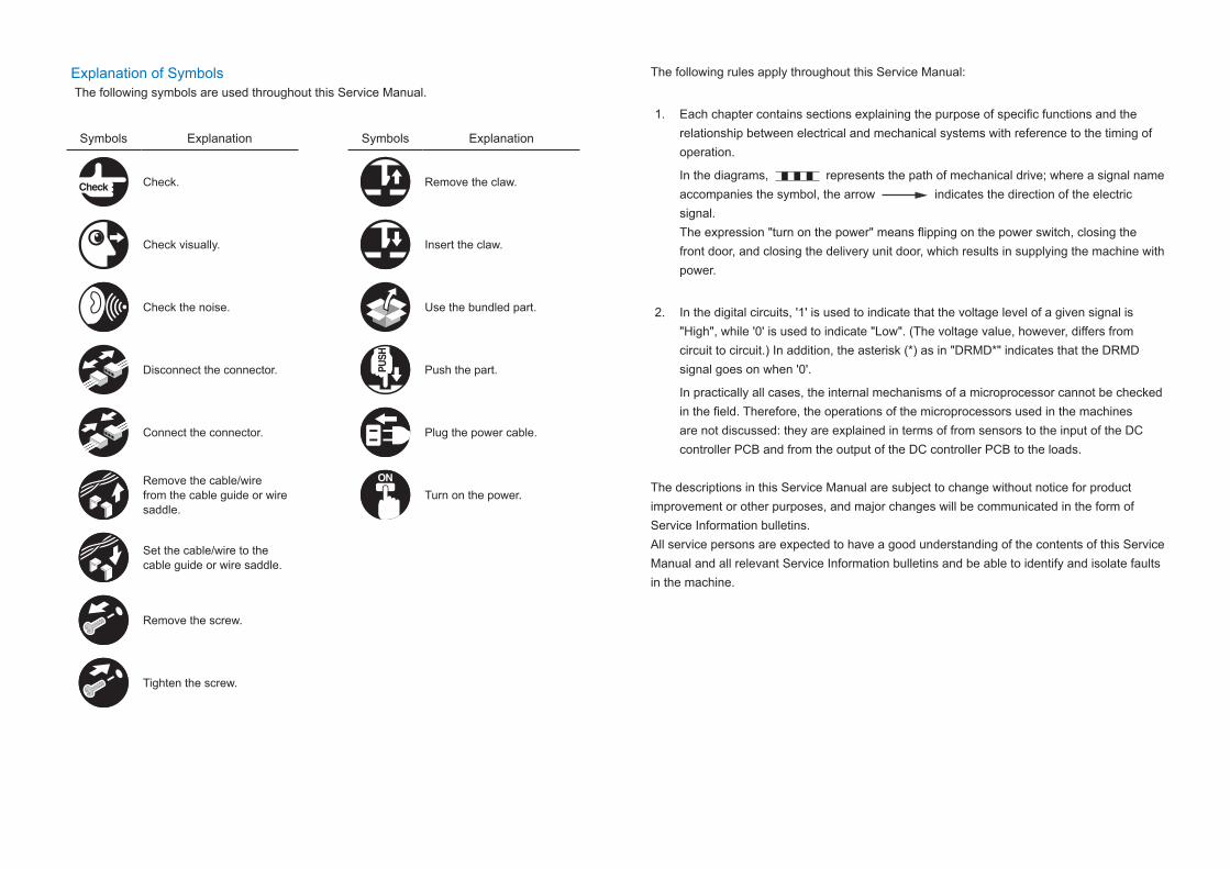
Explanation of SymbolsThe following symbols are used throughout this Service Manual.
Symbols Explanation Symbols Explanation
Check. Remove the claw.
Check visually. Insert the claw.
Check the noise. Use the bundled part.
Disconnect the connector. Push the part.
Connect the connector. Plug the power cable.
Remove the cable/wire from the cable guide or wire saddle.
Turn on the power.
Set the cable/wire to the cable guide or wire saddle.
Remove the screw.
Tighten the screw.
The following rules apply throughout this Service Manual:
1. Each chapter contains sections explaining the purpose of specific functions and the relationship between electrical and mechanical systems with reference to the timing of operation.
In the diagrams, represents the path of mechanical drive; where a signal name accompanies the symbol, the arrow indicates the direction of the electric signal. The expression "turn on the power" means flipping on the power switch, closing the front door, and closing the delivery unit door, which results in supplying the machine with power.
2. In the digital circuits, '1' is used to indicate that the voltage level of a given signal is "High", while '0' is used to indicate "Low". (The voltage value, however, differs from circuit to circuit.) In addition, the asterisk (*) as in "DRMD*" indicates that the DRMD signal goes on when '0'.
In practically all cases, the internal mechanisms of a microprocessor cannot be checked in the field. Therefore, the operations of the microprocessors used in the machines are not discussed: they are explained in terms of from sensors to the input of the DC controller PCB and from the output of the DC controller PCB to the loads.
The descriptions in this Service Manual are subject to change without notice for product improvement or other purposes, and major changes will be communicated in the form of Service Information bulletins.All service persons are expected to have a good understanding of the contents of this Service Manual and all relevant Service Information bulletins and be able to identify and isolate faults in the machine.
Contents1 Product Outline
Specifications ------------------------------------------------------------------1-2
2 TechnologyBasic Construction ------------------------------------------------------------2-2
Overview ----------------------------------------------------------------------------- 2-2Controls --------------------------------------------------------------------------2-2
FAX communication control ----------------------------------------------------- 2-2
3 Parts Replacing and CleaningParts List ------------------------------------------------------------------------3-2
PCBs ---------------------------------------------------------------------------------- 3-2Parts Replacing and Cleaning ---------------------------------------------3-3
PCBs ---------------------------------------------------------------------------------- 3-3G3 Fax Unit ---------------------------------------------------------------------------------- 3-3
4 Error CodeOverview ------------------------------------------------------------------------4-2
Guide to Error Code --------------------------------------------------------------- 4-2User Error Code ---------------------------------------------------------------4-3Service Error Code -----------------------------------------------------------4-3
5 Service ModeOutline ---------------------------------------------------------------------------5-2
Service Mode Composition ------------------------------------------------------ 5-2Using Service Mode --------------------------------------------------------------- 5-2Menu Items -------------------------------------------------------------------------- 5-4
Setting of Bit Switch (SSSW) ----------------------------------------------5-5Bit Switch Composition ----------------------------------------------------------- 5-5
SSSW-SW01 -------------------------------------------------------------------------------- 5-5SSSW-SW03 -------------------------------------------------------------------------------- 5-6
SSSW-SW04 -------------------------------------------------------------------------------- 5-7SSSW-SW05 -------------------------------------------------------------------------------- 5-8SSSW-SW12 -------------------------------------------------------------------------------- 5-9SSSW-SW14 -------------------------------------------------------------------------------5-10SSSW-SW24 -------------------------------------------------------------------------------5-10SSSW-SW25 -------------------------------------------------------------------------------5-11SSSW-SW26 -------------------------------------------------------------------------------5-11SSSW-SW28 -------------------------------------------------------------------------------5-12SSSW-SW30 -------------------------------------------------------------------------------5-13
Setting of Menu Switch (MENU) ---------------------------------------- 5-14Menu Switch Composition ------------------------------------------------------5-14
Setting of Numeric Parameter (NUMERIC Param.) ---------------- 5-15Numerical Parameter Composition -------------------------------------------5-15
Setting of Destination (TYPE) -------------------------------------------- 5-16Overview ----------------------------------------------------------------------------5-16
Setting of Printer Functions (PRINTER) ------------------------------- 5-17Setting of Bit Switch (SSSW) --------------------------------------------------5-17
SSSW-SW05 -------------------------------------------------------------------------------5-17SSSW-SW06 -------------------------------------------------------------------------------5-17
Setting of Numeric Parameter (NUMERIC Param.) ----------------------5-18Numerical Parameter Composition----------------------------------------------------5-18
Initialization of Set Value (CLEAR) ------------------------------------- 5-19Overview ----------------------------------------------------------------------------5-19
Test Mode (TEST) ---------------------------------------------------------- 5-20Outline -------------------------------------------------------------------------------5-20
Test Mode Construction ------------------------------------------------------------------5-20MODEM Test -----------------------------------------------------------------------5-21
Relay Test (RELAY-1) ---------------------------------------------------------------------5-21Frequency Test (FREQ) ------------------------------------------------------------------5-21G3 Signal Transmission Test (G3 Tx) ------------------------------------------------5-22DTMF Transmission Test ----------------------------------------------------------------5-23V.34 G3 Signal Transmission Test (V34G3Tx) -------------------------------------5-23
Function Test -----------------------------------------------------------------------5-244800-bps Signal Transmission Test ---------------------------------------------------5-24
Service Report (REPORT) ------------------------------------------------ 5-25System Data List ------------------------------------------------------------------5-25System Dump List ----------------------------------------------------------------5-25
Error Transmission Report ------------------------------------------------------5-26
6 InstallationHow to Check this Installation Procedure -------------------------------6-2
When Using the Parts Included in the Package---------------------------- 6-2Symbols in the Illustration ------------------------------------------------------- 6-2
Check Items when Turning OFF the Main Power ---------------------6-2Installation Outline Drawing ------------------------------------------------6-2Checking the Contents ------------------------------------------------------6-3Installation Procedure --------------------------------------------------------6-4
Installing the Fax Board-AK1 ------------------------------------------------------------ 6-4Procedure after Work ---------------------------------------------------------------------- 6-7
Operation Setting -------------------------------------------------------------6-8Type Setting ---------------------------------------------------------------------------------- 6-8Basic Setting --------------------------------------------------------------------------------- 6-8Fax communication test ------------------------------------------------------------------- 6-8
1
1 Product OutlineProduct Outline
Product Outline ■Specifications
1
1 Product Outline
Product Outline
1-2
1-2
Product Outline > Specifications
Product Outline > Specifications
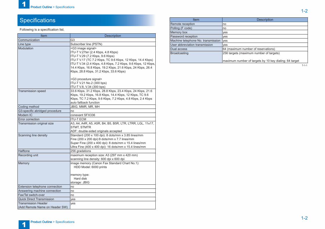
SpecificationsFollowing is a specification list.
Item DescriptionCommunication G3Line type Subscriber line (PSTN)Modulation <G3 image signal>
ITU-T V.27ter (2.4 Kbps, 4.8 Kbps)ITU-T V.29 (7.2 Kbps, 9.6 Kbps)ITU-T V.17 (TC 7.2 Kbps, TC 9.6 Kbps, 12 Kbps, 14.4 Kbps)ITU-T V.34 (2.4 Kbps, 4.8 Kbps, 7.2 Kbps, 9.6 Kbps, 12 Kbps, 14.4 Kbps, 16.8 Kbps, 19.2 Kbps, 21.6 Kbps, 24 Kbps, 26.4 Kbps, 28.8 Kbps, 31.2 Kbps, 33.6 Kbps)
<G3 procedure signal>ITU-T V.21 No.2 (300 bps)ITU-T V.8, V.34 (300 bps)
Transmission speed 33.6 Kbps, 31.2 Kbps, 28.8 Kbps, 23.4 Kbps, 24 Kbps, 21.6 Kbps, 19.2 Kbps, 16.8 Kbps, 14.4 Kbps, 12 Kbps, TC 9.6 Kbps, TC 7.2 Kbps, 9.6 Kbps, 7.2 Kbps, 4.8 Kbps, 2.4 Kbpsauto fallback function
Coding method JBIG, MMR, MR, MHG3-specific abridged procedure noModem IC conexant SFX336Error correction ITU-T ECMTransmission original size A3, A4, A4R, A5, A5R, B4, B5, B5R, LTR, LTRR, LGL, 11x17,
STMT, STMTRADF: double-sided originals accepted
Scanning line density Standard (200 x 100 dpi): 8 dots/mm x 3.85 lines/mmFine (200 x 200 dpi):8 dots/mm x 7.7 lines/mmSuper Fine (200 x 400 dpi): 8 dots/mm x 15.4 lines/mmUltra Fine (400 x 400 dpi): 16 dots/mm x 15.4 lines/mm
Halftone 256 gradationsRecording unit maximum reception size: A3 (297 mm x 420 mm)
scanning line density: 600 dpi x 600 dpiMemory image memory (Canon Fax Standard Chart No.1):
HDD Model: 6000 prints
memory type:Hard disk
storage: JBIGExtension telephone connection noAnswering machine connection noFax/Tel switch-over noQuick Direct Transmission yesTransmission Header(Add Remote Name on Header SW)
yes
Item DescriptionRemote reception noPolling (F code) noMemory box yesPassword reception yesMachine telephone No. transmission yesUser abbreviation transmission yesDual access 64 (maximum number of reservations)Broadcasting 256 targets (maximum number of targets)
maximum number of targets by 10 key dialing: 64 targetT-1-1

2
2 TechnologyTechnology
Technology ■Basic Construction ■Controls

2
2 Technology
Technology
2-2
2-2
Technology > Controls > FAX communication control
Technology > Controls > FAX communication control
Basic Construction
OverviewThis product is a FAX unit for adding FAX lines to the machine.This machine is equipped with a telephone-based communication function and an image processing function to enable a digital copier to serve as a highly functional multi-function fax machine.As for image transmission speed, it is capable of communicating at 33.6 kbps (max.) thanks to a modem for V.34, which comply with ITU-T standard.
[1]
[2]
[1] Super G3 FAX Board-AK1[2] G3 FAX PCB
F-2-1
Controls
FAX communication controlThe main controller in the machine executes FAX communication control.The FAX control program is loaded on the main controller and controls the G3 FAX PCB in the FAX unit.
FAX interface G3 FAX PCB
Main controller 1Modular PCB
off-hook detectPCB
FAX unit for one lineCopier
Speaker
F-2-2
3
3 Parts Replacing and CleaningParts Replacing and Cleaning
Parts Replacing and Cleaning ■Parts List ■Parts Replacing and Cleaning

3
3 Parts Replacing and Cleaning
Parts Replacing and Cleaning
3-2
3-2
Parts Replacing and Cleaning > Parts List > PCBs
Parts Replacing and Cleaning > Parts List > PCBs
Parts List
PCBsNo. Part name Reference[1] G3 FAX PCB -[2] Off-hook Detection PCB -[3] Modular PCB -
[2]
[1]
[3]
T-3-1
F-3-1
3
3 Parts Replacing and Cleaning
Parts Replacing and Cleaning
3-3
3-3
Parts Replacing and Cleaning > Parts Replacing and Cleaning > PCBs > G3 Fax Unit
Parts Replacing and Cleaning > Parts Replacing and Cleaning > PCBs > G3 Fax Unit
Parts Replacing and Cleaning
PCBs ■ G3 Fax Unit
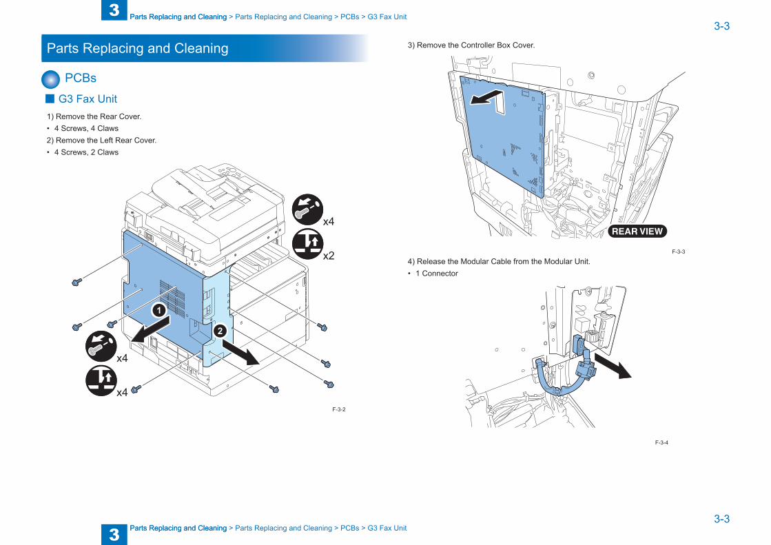
1) Remove the Rear Cover.• 4 Screws, 4 Claws2) Remove the Left Rear Cover.• 4 Screws, 2 Claws
x4
x2
x4
x4F-3-2
3) Remove the Controller Box Cover.
4) Release the Modular Cable from the Modular Unit.• 1 Connector
F-3-3
F-3-4

3
3 Parts Replacing and Cleaning
Parts Replacing and Cleaning
3-4
3-4
Parts Replacing and Cleaning > Parts Replacing and Cleaning > PCBs > G3 Fax Unit
Parts Replacing and Cleaning > Parts Replacing and Cleaning > PCBs > G3 Fax Unit
5) Remove the Fax Unit Cover.• 2 Edge Saddles, 3 Screws
x3
x2
6) Release the Modular Cable from the Fax Unit PCB.• 1 Connector
F-3-5
F-3-6
7) Release the 2 harnesses of the Fax Unit in place, and release the harnesses from the Controller PCB.
• 2 Connectors, 2 Edge Saddles
x2
x2
8) Remove the G3 Fax Unit.• 2 Claws, 4 Screws
x4
x2
F-3-7
F-3-8
4
4 Error CodeError Code
Error Code ■Overview ■User Error Code ■Service Error Code
4
4 Error Code
Error Code
4-2
4-2
Error Code > Overview > Guide to Error Code
Error Code > Overview > Guide to Error Code
Overview
Guide to Error CodeWhen the Board has been installed and '1' is set for service data #1 SSSW SW01 bit 0, communications ending in error will be indicated in the following reports using service error codes: communications management report, reception result report, and error transmission report.You can also check the code of an error by making the following selections: System Monitor > Fax > Detail.
The major error codes used by the Board are listed on the pages that follow. For information on causes and remedies in connection with other error codes, see the "G3/G4 Facsimile Error Code List" (HY8-23A0-020).If the Board indicates a service error code, try the following:
- Increase the transmission level. Set -8 (dBm) for service data #2 MENU parameter No. 007.
- Decrease the transmission level. Set -15 (dBm) to service data #2 MENU parameter No. 007.
- Provide a remedy against echoes. Change the following bit setting for service data #1 SSSW SW03:
Bit4 -> 1: to cause the machine to ignore the first DIS signal from the other party.-> 0: to cause the machine to ignore the first DIS signal from the other party.
Bit5 -> 1: to cause the machine to transmit a tonal signal (1850 or 1650 Hz) in response to the DIS signal from the other party.
-> 0: to cause the machine not to send a total signal (1850 or 1650 Hz) in response to the DIS signal from the other party.
Bit6 -> 1: to cause the machine to send a 1850-Hz tonal signal if bit 5 is set to '1'.-> 0: to cause the machine to send a 1650-Hz tonal signal if bit 5 is set to '1'.
Bit7 -> 1: to cause the machine to send a total signal before sending the CED signal.-> 0: to causes the machine not to send a tonal signal before sending the CED signal.
- EPT (echo protect tone) Change the setting of service data #1 SSSW SW03 bit 1:
Bit1 -> 1: to cause the machine to send EPT.-> 0: to cause the machine not to send EPT.
- Adjust the NL equalizer. Set '1' for serve data #2 MENU parameter No. 005.
- Decrease the transmission start speed. Decrease the transmission start speed in user mode: System Settings > Communications Settings > Fax Settings > Send Start Speed.
- Make the TCF evaluation standards lenient. The Board does not offer a means by which to provide this remedy.
- Make the RTN transmissions conditions lenient. Change parameters No. 2 through No. 004 of service data #3 NUMERIC Param. No. 002: error rate for all lines; change it so that it is closer to 99%. No. 003: number of lines in connection with bursts; change it so that it is closer to 99 lines. No. 004: number of errors falling short of a specific number of lines in connection with bursts; change it so that it is closer to 99.
- Increase the length of silence after reception of CFR. Set '1' for service data #1 SSSW SW04 bit 4.
Bit4 -> 1: length of time during which a low-speed signal is ignored after transmission of CFR; 1500 msec
-> 0: length of time during which a low-speed signal is ignored after transmission of CFR; 700 msec
4
4 Error Code
Error Code
4-3
4-3
Error Code > Service Error Code
Error Code > Service Error Code
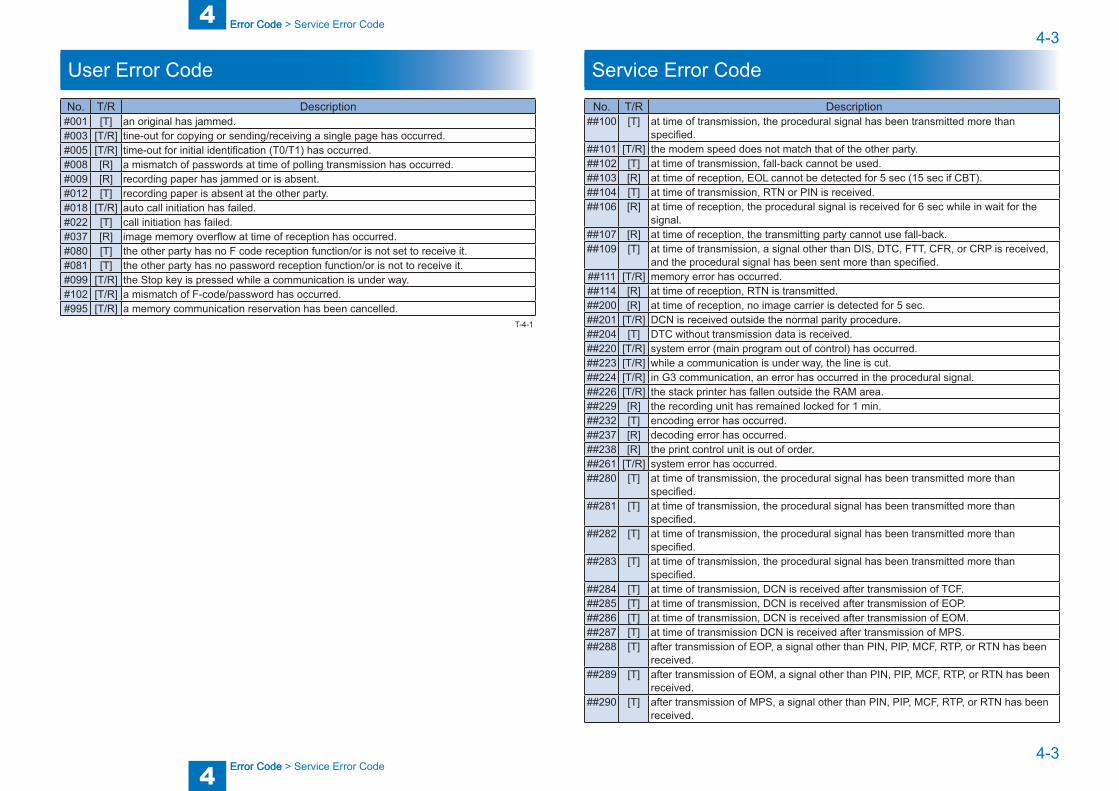
User Error Code
No. T/R Description#001 [T] an original has jammed.#003 [T/R] tine-out for copying or sending/receiving a single page has occurred.#005 [T/R] time-out for initial identification (T0/T1) has occurred.#008 [R] a mismatch of passwords at time of polling transmission has occurred.#009 [R] recording paper has jammed or is absent.#012 [T] recording paper is absent at the other party.#018 [T/R] auto call initiation has failed.#022 [T] call initiation has failed.#037 [R] image memory overflow at time of reception has occurred.#080 [T] the other party has no F code reception function/or is not set to receive it.#081 [T] the other party has no password reception function/or is not to receive it.#099 [T/R] the Stop key is pressed while a communication is under way.#102 [T/R] a mismatch of F-code/password has occurred.#995 [T/R] a memory communication reservation has been cancelled.
T-4-1
Service Error Code
No. T/R Description##100 [T] at time of transmission, the procedural signal has been transmitted more than
specified.##101 [T/R] the modem speed does not match that of the other party.##102 [T] at time of transmission, fall-back cannot be used.##103 [R] at time of reception, EOL cannot be detected for 5 sec (15 sec if CBT).##104 [T] at time of transmission, RTN or PIN is received.##106 [R] at time of reception, the procedural signal is received for 6 sec while in wait for the
signal.##107 [R] at time of reception, the transmitting party cannot use fall-back.##109 [T] at time of transmission, a signal other than DIS, DTC, FTT, CFR, or CRP is received,
and the procedural signal has been sent more than specified.##111 [T/R] memory error has occurred.##114 [R] at time of reception, RTN is transmitted.##200 [R] at time of reception, no image carrier is detected for 5 sec.##201 [T/R] DCN is received outside the normal parity procedure.##204 [T] DTC without transmission data is received.##220 [T/R] system error (main program out of control) has occurred.##223 [T/R] while a communication is under way, the line is cut.##224 [T/R] in G3 communication, an error has occurred in the procedural signal.##226 [T/R] the stack printer has fallen outside the RAM area.##229 [R] the recording unit has remained locked for 1 min.##232 [T] encoding error has occurred.##237 [R] decoding error has occurred.##238 [R] the print control unit is out of order.##261 [T/R] system error has occurred.##280 [T] at time of transmission, the procedural signal has been transmitted more than
specified.##281 [T] at time of transmission, the procedural signal has been transmitted more than
specified.##282 [T] at time of transmission, the procedural signal has been transmitted more than
specified.##283 [T] at time of transmission, the procedural signal has been transmitted more than
specified.##284 [T] at time of transmission, DCN is received after transmission of TCF.##285 [T] at time of transmission, DCN is received after transmission of EOP.##286 [T] at time of transmission, DCN is received after transmission of EOM.##287 [T] at time of transmission DCN is received after transmission of MPS.##288 [T] after transmission of EOP, a signal other than PIN, PIP, MCF, RTP, or RTN has been
received.##289 [T] after transmission of EOM, a signal other than PIN, PIP, MCF, RTP, or RTN has been
received.##290 [T] after transmission of MPS, a signal other than PIN, PIP, MCF, RTP, or RTN has been
received.
4
4 Error Code
Error Code
4-4
4-4
Error Code > Service Error Code
Error Code > Service Error Code
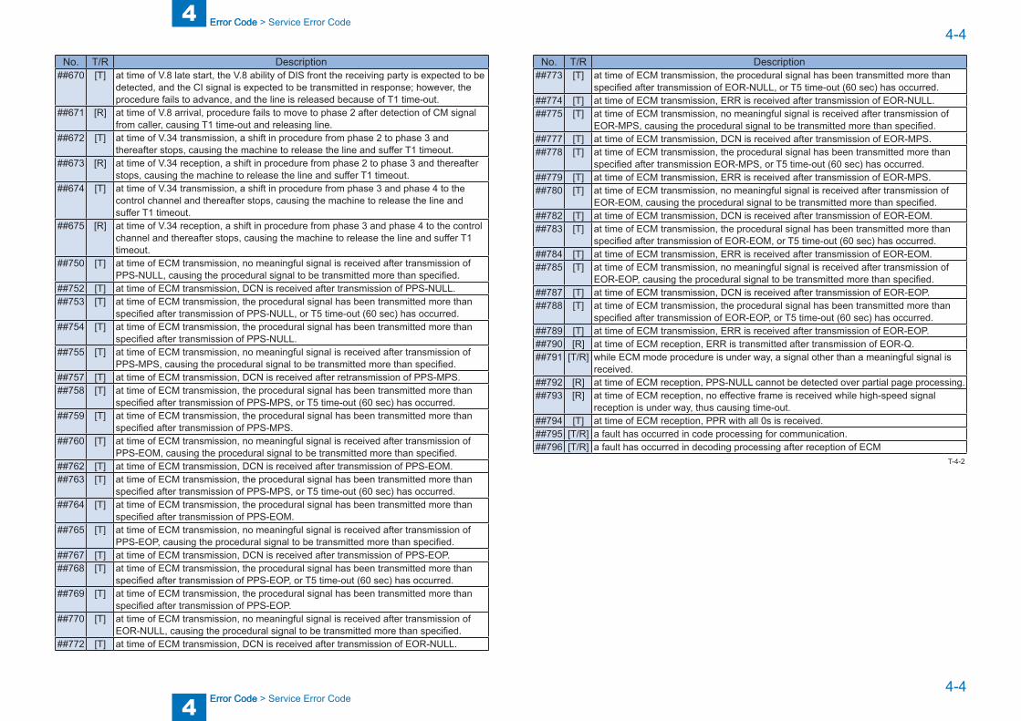
No. T/R Description##670 [T] at time of V.8 late start, the V.8 ability of DIS front the receiving party is expected to be
detected, and the CI signal is expected to be transmitted in response; however, the procedure fails to advance, and the line is released because of T1 time-out.
##671 [R] at time of V.8 arrival, procedure fails to move to phase 2 after detection of CM signal from caller, causing T1 time-out and releasing line.
##672 [T] at time of V.34 transmission, a shift in procedure from phase 2 to phase 3 and thereafter stops, causing the machine to release the line and suffer T1 timeout.
##673 [R] at time of V.34 reception, a shift in procedure from phase 2 to phase 3 and thereafter stops, causing the machine to release the line and suffer T1 timeout.
##674 [T] at time of V.34 transmission, a shift in procedure from phase 3 and phase 4 to the control channel and thereafter stops, causing the machine to release the line and suffer T1 timeout.
##675 [R] at time of V.34 reception, a shift in procedure from phase 3 and phase 4 to the control channel and thereafter stops, causing the machine to release the line and suffer T1 timeout.
##750 [T] at time of ECM transmission, no meaningful signal is received after transmission of PPS-NULL, causing the procedural signal to be transmitted more than specified.
##752 [T] at time of ECM transmission, DCN is received after transmission of PPS-NULL.##753 [T] at time of ECM transmission, the procedural signal has been transmitted more than
specified after transmission of PPS-NULL, or T5 time-out (60 sec) has occurred.##754 [T] at time of ECM transmission, the procedural signal has been transmitted more than
specified after transmission of PPS-NULL.##755 [T] at time of ECM transmission, no meaningful signal is received after transmission of
PPS-MPS, causing the procedural signal to be transmitted more than specified.##757 [T] at time of ECM transmission, DCN is received after retransmission of PPS-MPS.##758 [T] at time of ECM transmission, the procedural signal has been transmitted more than
specified after transmission of PPS-MPS, or T5 time-out (60 sec) has occurred.##759 [T] at time of ECM transmission, the procedural signal has been transmitted more than
specified after transmission of PPS-MPS.##760 [T] at time of ECM transmission, no meaningful signal is received after transmission of
PPS-EOM, causing the procedural signal to be transmitted more than specified.##762 [T] at time of ECM transmission, DCN is received after transmission of PPS-EOM.##763 [T] at time of ECM transmission, the procedural signal has been transmitted more than
specified after transmission of PPS-MPS, or T5 time-out (60 sec) has occurred.##764 [T] at time of ECM transmission, the procedural signal has been transmitted more than
specified after transmission of PPS-EOM.##765 [T] at time of ECM transmission, no meaningful signal is received after transmission of
PPS-EOP, causing the procedural signal to be transmitted more than specified.##767 [T] at time of ECM transmission, DCN is received after transmission of PPS-EOP.##768 [T] at time of ECM transmission, the procedural signal has been transmitted more than
specified after transmission of PPS-EOP, or T5 time-out (60 sec) has occurred.##769 [T] at time of ECM transmission, the procedural signal has been transmitted more than
specified after transmission of PPS-EOP.##770 [T] at time of ECM transmission, no meaningful signal is received after transmission of
EOR-NULL, causing the procedural signal to be transmitted more than specified.##772 [T] at time of ECM transmission, DCN is received after transmission of EOR-NULL.
No. T/R Description##773 [T] at time of ECM transmission, the procedural signal has been transmitted more than
specified after transmission of EOR-NULL, or T5 time-out (60 sec) has occurred.##774 [T] at time of ECM transmission, ERR is received after transmission of EOR-NULL.##775 [T] at time of ECM transmission, no meaningful signal is received after transmission of
EOR-MPS, causing the procedural signal to be transmitted more than specified.##777 [T] at time of ECM transmission, DCN is received after transmission of EOR-MPS.##778 [T] at time of ECM transmission, the procedural signal has been transmitted more than
specified after transmission EOR-MPS, or T5 time-out (60 sec) has occurred.##779 [T] at time of ECM transmission, ERR is received after transmission of EOR-MPS.##780 [T] at time of ECM transmission, no meaningful signal is received after transmission of
EOR-EOM, causing the procedural signal to be transmitted more than specified.##782 [T] at time of ECM transmission, DCN is received after transmission of EOR-EOM.##783 [T] at time of ECM transmission, the procedural signal has been transmitted more than
specified after transmission of EOR-EOM, or T5 time-out (60 sec) has occurred.##784 [T] at time of ECM transmission, ERR is received after transmission of EOR-EOM.##785 [T] at time of ECM transmission, no meaningful signal is received after transmission of
EOR-EOP, causing the procedural signal to be transmitted more than specified.##787 [T] at time of ECM transmission, DCN is received after transmission of EOR-EOP.##788 [T] at time of ECM transmission, the procedural signal has been transmitted more than
specified after transmission of EOR-EOP, or T5 time-out (60 sec) has occurred.##789 [T] at time of ECM transmission, ERR is received after transmission of EOR-EOP.##790 [R] at time of ECM reception, ERR is transmitted after transmission of EOR-Q.##791 [T/R] while ECM mode procedure is under way, a signal other than a meaningful signal is
received.##792 [R] at time of ECM reception, PPS-NULL cannot be detected over partial page processing.##793 [R] at time of ECM reception, no effective frame is received while high-speed signal
reception is under way, thus causing time-out.##794 [T] at time of ECM reception, PPR with all 0s is received.##795 [T/R] a fault has occurred in code processing for communication.##796 [T/R] a fault has occurred in decoding processing after reception of ECM
T-4-2

5
5 Service ModeService Mode
Service Mode ■Outline ■Setting of Bit Switch (SSSW) ■Setting of Menu Switch (MENU) ■Setting of Numeric Parameter (NUMERIC Param.) ■Setting of Destination (TYPE) ■Setting of Printer Functions (PRINTER) ■Initialization of Set Value (CLEAR) ■Test Mode (TEST) ■Service Report (REPORT)

5
5 Service Mode
Service Mode
5-2
5-2
Service Mode > Outline > Using Service Mode
Service Mode > Outline > Using Service Mode
Outline
Service Mode CompositionThe Board's service mode consists of the following 10 items (#1 through #10):
Item Name Description#1 SSSW service soft switch Use it to register/set up functions related to
basic fax services (e.g., error management, echo remedies, communication remedies).
#2 MENU menu switch setting Use it to register/setup functions needed at time of installation (e.g., NL equalizer, transmission level).
#3 NUMERIC Param numeric parameter settings Use it to enter numeric parameters.#4 NCU not to be used for service work All settings under the item will collectively set
in response to the #5 TYPE setting.#5 TYPE country settings Use it to cause the Board to automatically
set data under #4 NCU so that it complies with the communication requirements of the country in question.
#6 ISDN - -#7 PRINTER printer functions setup Use it to register/set up functions related
to basic printer services (e.g., reduction for received images).
#8 CLEAR data initialization Use it to reset various data to initial settings.#9 TEST test mode Use it to execute various tests.#10 REPORT service report Use it to print out reports.
Caution:
T-5-1
Using Service Mode
1) Press the User Mode key " " on the control panel.2) Press the keys 2 and 8 on the keypad at the same time.
3) Press the User Mode key " " on the control panel once again. The machine will indicate the accessories that are connected to it (e.g., FEEDER, FAX,
BOARD).
Select [FAX] to use service mode items available for the Board.
COPIER
FEEDER
BOARD
FAX
SERVICE MODE LEVEL 1
COPIER: service mode of the host machine.FEEDER: service mode of the ADF. (*)FAX: service mode of the fax. (*)BOARD: service mode of an accessory board. (*)
*: Indicated only if installed.
F-5-1
5
5 Service Mode
Service Mode
5-3
5-3
Service Mode > Outline > Using Service Mode
Service Mode > Outline > Using Service Mode
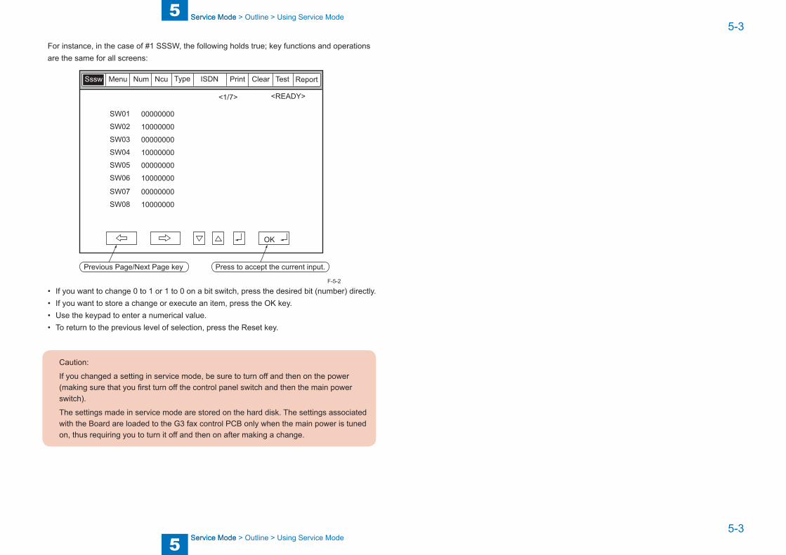
For instance, in the case of #1 SSSW, the following holds true; key functions and operations are the same for all screens:
<1/7> <READY>
ReportSssw Menu Num Ncu Type ISDN Print Clear Test
00000000
10000000
00000000
10000000
00000000
10000000
SW01
SW02
SW03
SW04
SW05
SW06
00000000
10000000
SW07
SW08
OK
Press to accept the current input.Previous Page/Next Page key
• If you want to change 0 to 1 or 1 to 0 on a bit switch, press the desired bit (number) directly.• If you want to store a change or execute an item, press the OK key.• Use the keypad to enter a numerical value.• To return to the previous level of selection, press the Reset key.
Caution:
If you changed a setting in service mode, be sure to turn off and then on the power (making sure that you first turn off the control panel switch and then the main power switch).
The settings made in service mode are stored on the hard disk. The settings associated with the Board are loaded to the G3 fax control PCB only when the main power is tuned on, thus requiring you to turn it off and then on after making a change.
F-5-2
5
5 Service Mode
Service Mode
5-4
5-4
Service Mode > Outline > Menu Items
Service Mode > Outline > Menu Items
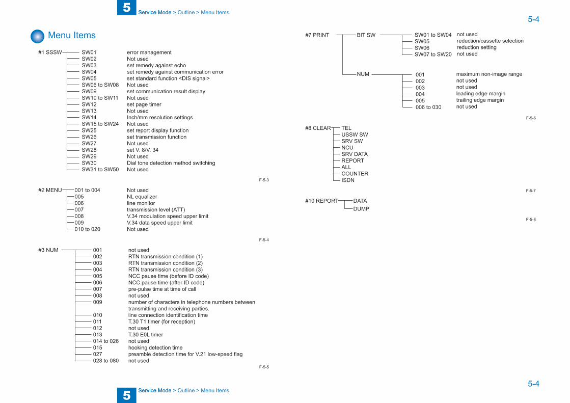
Menu Items
#1 SSSW SW01 error management SW02 Not used SW03 set remedy against echo SW04 set remedy against communication error SW05 set standard function <DIS signal> SW06 to SW08 Not used SW09 set communication result display SW10 to SW11 Not used SW12 set page timer SW13 Not used SW14 Inch/mm resolution settings SW15 to SW24 Not used SW25 set report display function SW26 set transmission function SW27 Not used SW28 set V. 8/V. 34 SW29 Not used SW30 Dial tone detection method switching SW31 to SW50 Not used
#2 MENU 001 to 004 Not used 005 NL equalizer 006 line monitor 007 transmission level (ATT) 008 V.34 modulation speed upper limit 009 V.34 data speed upper limit 010 to 020 Not used
#3 NUM 001 not used 002 RTN transmission condition (1) 003 RTN transmission condition (2) 004 RTN transmission condition (3) 005 NCC pause time (before ID code) 006 NCC pause time (after ID code) 007 pre-pulse time at time of call 008 not used 009 number of characters in telephone numbers between transmitting and receiving parties. 010 line connection identification time 011 T.30 T1 timer (for reception) 012 not used 013 T.30 E0L timer 014 to 026 not used 015 hooking detection time 027 preamble detection time for V.21 low-speed flag 028 to 080 not used
F-5-3
F-5-4
F-5-5
#7 PRINT BIT SW
NUM
SW01 to SW04SW05SW06SW07 to SW20
not usedreduction/cassette selectionreduction settingnot used
001002003004005006 to 030
maximum non-image rangenot usednot usedleading edge margintrailing edge marginnot used
#8 CLEAR TEL USSW SW SRV SW NCU SRV DATA REPORT ALL COUNTER ISDN
#10 REPORT DATA DUMP
F-5-6
F-5-7
F-5-8
5
5 Service Mode
Service Mode
5-5
5-5
Service Mode > Setting of Bit Switch (SSSW) > Bit Switch Composition > SSSW-SW01
Service Mode > Setting of Bit Switch (SSSW) > Bit Switch Composition > SSSW-SW01
Setting of Bit Switch (SSSW)
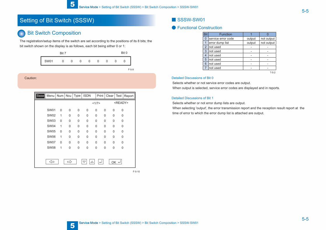
Bit Switch CompositionThe registration/setup items of the switch are set according to the positions of its 8 bits; the bit switch shown on the display is as follows, each bit being either 0 or 1:
SW01 0 0 0 0 0 0 0 0
Bit 7 Bit 0
Caution:
<1/7> <READY>
ReportSssw Menu Num Ncu Type ISDN Print Clear Test
0 0 0 0 0 0 0 0
1 0 0 0 0 0 0 0
0 0 0 0 0 0 0 0
1 0 0 0 0 0 0 0
0 0 0 0 0 0 0 0
1 0 0 0 0 0 0 0
SW01
SW02
SW03
SW04
SW05
SW06
0 0 0 0 0 0 0 0
1 0 0 0 0 0 0 0
SW07
SW08
OK
F-5-9
F-5-10
■ SSSW-SW01
● Functional ConstructionBit Function 1 00 service error code output not output1 error dump list output not output2 not used - -3 not used - -4 not used - -5 not used - -6 not used - -7 not used - -
Detailed Discussions of Bit 0Selects whether or not service error codes are output.When output is selected, service error codes are displayed and in reports.
Detailed Discussions of Bit 1Selects whether or not error dump lists are output.When selecting 'output', the error transmission report and the reception result report at the time of error to which the error dump list is attached are output.
T-5-2

5
5 Service Mode
Service Mode
5-6
5-6
Service Mode > Setting of Bit Switch (SSSW) > Bit Switch Composition > SSSW-SW03
Service Mode > Setting of Bit Switch (SSSW) > Bit Switch Composition > SSSW-SW03
■ SSSW-SW03
● Functional ConstructionBit Function 1 00 not used - -1 echo protect tone at high-speed
transmissiontransmit do not transmit
2 not used - -3 not used - -4 transmission mode: international
transmission (1)use do not use
5 transmission mode: international transmission (2) or (3)
use do not use
6 transmission mode international transmission (3)
international transmission (2)
7 tonal signal before CED signal transmission transmit do not transmit
Detailed Discussions of Bit 1Use it to enable/disable transmission of an echo protect tone for a high-speed transmission V.29 modem signal (transmission speed at 9600 or 7200 bps).If errors occur frequently at time of transmission because of the condition of the line, select 'transmit' so that a non-modulation carrier will be transmitted as a pre-image transmission sync signal for about 200 msec.
Error Code:Any of the following error codes may be indicated because of the line condition at time of transmission##100, ##104, ##281, ##283, ##750, ##755, ##760, ##765
Detailed Discussions of Bits 4, 5, and 6Use it to select an appropriate transmission mode: international transmission (1), international transmission (2), or international transmission (3).Use the service soft switch or the dial registration function to select the appropriate transmission mode if errors occur frequently at time of transmission to overseas.
Error Code:Any of the following error codes may be indicated because of an echo at time of transmission##005, ##100, ##101, ##102, ##104, ##201, ##280, ##281, ##283, ##284, ##750, ##760, ##765, ##774, ##779, ##784, ##794
T-5-3
Using the Dial Recognition Function (user level):Select 'international transmission (1)' when making an entry in the Address Book. If errors still occur, select 'international transmission (2)' and then 'international transmission (3)' in sequence until errors stop. The transmission mode selected using the One-Touch Dial function or the Speed Dial function will be give priority over the setting made by the service soft switch.An international transmission mode may be selected using the keypad if a mode has been selected using this switch; for settings, see the following table:
Transmission mode Bit7 Bit6 Bit5 Bit4 Bit3 Bit2 Bit1 Bit0International transmission (1) * 0 0 1 0 0 * 0International transmission (2) * 0 1 0 0 0 * 0International transmission (3) * 1 1 0 0 0 * 0
International transmission (1): select it to ignore the first DIS signal from the other party.International transmission (2): select it to transmit a 1850-Hz total signal when transmitting
the DIS signal.International transmission (3): select it to transmit a 1650-Hz total signal when transmitting
the DIS signal.
Detailed Discussions of Bit 7Use it to enable/disable transmission of a 1080-Hz tonal signal before transmission of the CED signal.Select 'transmit' if errors occur frequently because of an echo when reception is from overseas.
Error Code:Any of the following error code may be indicated because of an echo at time of reception##005, ##101, ##106, ##107, ##114, ##200, ##201, ##790
T-5-4
5
5 Service Mode
Service Mode
5-7
5-7
Service Mode > Setting of Bit Switch (SSSW) > Bit Switch Composition > SSSW-SW04
Service Mode > Setting of Bit Switch (SSSW) > Bit Switch Composition > SSSW-SW04
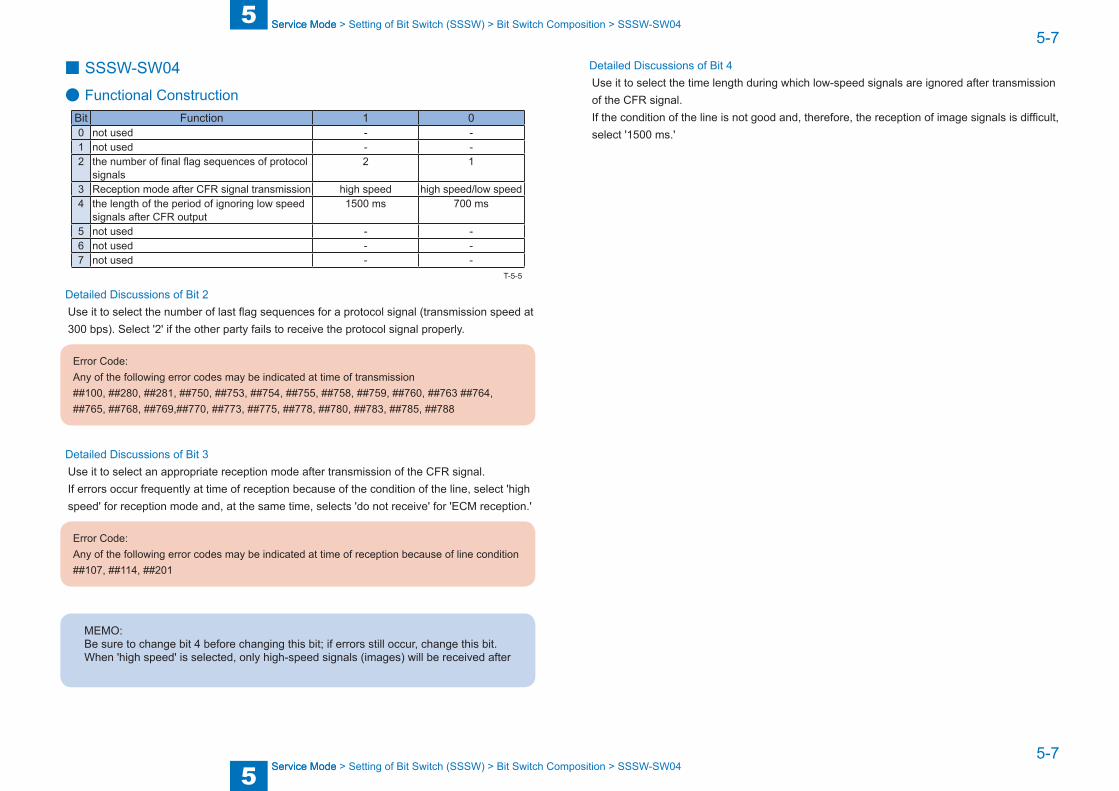
■ SSSW-SW04
● Functional ConstructionBit Function 1 00 not used - -1 not used - -2 the number of final flag sequences of protocol
signals2 1
3 Reception mode after CFR signal transmission high speed high speed/low speed4 the length of the period of ignoring low speed
signals after CFR output1500 ms 700 ms
5 not used - -6 not used - -7 not used - -
Detailed Discussions of Bit 2Use it to select the number of last flag sequences for a protocol signal (transmission speed at 300 bps). Select '2' if the other party fails to receive the protocol signal properly.
Error Code:Any of the following error codes may be indicated at time of transmission##100, ##280, ##281, ##750, ##753, ##754, ##755, ##758, ##759, ##760, ##763 ##764, ##765, ##768, ##769,##770, ##773, ##775, ##778, ##780, ##783, ##785, ##788
Detailed Discussions of Bit 3Use it to select an appropriate reception mode after transmission of the CFR signal.If errors occur frequently at time of reception because of the condition of the line, select 'high speed' for reception mode and, at the same time, selects 'do not receive' for 'ECM reception.'
Error Code:Any of the following error codes may be indicated at time of reception because of line condition##107, ##114, ##201
MEMO:Be sure to change bit 4 before changing this bit; if errors still occur, change this bit.When 'high speed' is selected, only high-speed signals (images) will be received after
T-5-5
Detailed Discussions of Bit 4Use it to select the time length during which low-speed signals are ignored after transmission of the CFR signal.If the condition of the line is not good and, therefore, the reception of image signals is difficult, select '1500 ms.'

5
5 Service Mode
Service Mode
5-8
5-8
Service Mode > Setting of Bit Switch (SSSW) > Bit Switch Composition > SSSW-SW05
Service Mode > Setting of Bit Switch (SSSW) > Bit Switch Composition > SSSW-SW05
■ SSSW-SW05
● Functional ConstructionBit Function 1 00 not used - -1 Conversion from mm to inch (text mode) convert do not convert2 Conversion from mm to inch (text/photo mode) convert do not convert3 end DIS signal bits 33 and over prohibit do not prohibit4 Recording paper length availability declared in DIS signal A4/B4 size any size5 not used - -6 not used - -7 not used - -
Detailed Discussions of Bit 1Use it to enable/disable millimeter/inch conversion in sub scanning direction for images read in text mode.
Detailed Discussions of Bit 2Use it to enable/disable millimeter/inch conversion in sub scanning direction for images read in text/photo mode while bit 1 is set to '1'.
Detailed Discussions of Bit 3Use it to enable/disable transmission of bit 33 and thereafter (DIS signal).
Caution:
If 'prohibit' is selected, the Super Fine reception function or Memory Box function cannot
Detailed Discussions of Bit 4Use it to enable/disable declaration of the use of cut sheets (DIS signal).For reception of an extra-long original, select 'A4/B4 size' if division is to be by the other party.
MEMO:
T-5-6

5
5 Service Mode
Service Mode
5-9
5-9
Service Mode > Setting of Bit Switch (SSSW) > Bit Switch Composition > SSSW-SW12
Service Mode > Setting of Bit Switch (SSSW) > Bit Switch Composition > SSSW-SW12
■ SSSW-SW12
● Functional ConstructionBit Function 1 00 Time-out period for one page upon transmission 1 01 Time-out period for one page upon transmission 1 02 Time-out period for one page upon (HT transmission) 1 03 Time-out period for one page upon (HT transmission) 1 04 Time-out period for one page upon reception 1 05 Time-out period for one page upon reception 1 06 not used - -7 Respective page timer settings for transmission and for reception enable do not enable
The machine will stop the ongoing communication if the transmission/reception of a single original page takes 32 min or more. To use the timer for a purpose other than this function, refer to the tables that follow, and select an appropriate time length.When 'do not enable' is selected using bit 7, the time-out length for a single page for all modes will depend on the setting of bit 0 and bit 1.
T-5-7
Time-Out Length for Transmission/Reception
Bit7 Bit6 Bit5 Bit4 Bit3 Bit2 Bit1 Bit08 min 0 * * * * * 0 0
16 min 0 * * * * * 0 132 min 0 * * * * * 1 064 min 0 * * * * * 1 1
Time-Out Length for Transmission (in text mode)
Bit7 Bit6 Bit5 Bit4 Bit3 Bit2 Bit1 Bit08 min 1 * * * * * 0 0
16 min 1 * * * * * 0 132 min 1 * * * * * 1 064 min 1 * * * * * 1 1
Time-Out Length for Transmission (image mode other than text mode)
Bit7 Bit6 Bit5 Bit4 Bit3 Bit2 Bit1 Bit08 min 1 * * * 0 0 * *
16 min 1 * * * 0 1 * *32 min 1 * * * 1 0 * *64 min 1 * * * 1 1 * *
Time-Out Length for Reception
Bit7 Bit6 Bit5 Bit4 Bit3 Bit2 Bit1 Bit08 min 1 * 0 0 * * * *
16 min 1 * 0 1 * * * *32 min 1 * 1 0 * * * *64 min 1 * 1 1 * * * *
T-5-8
T-5-9
T-5-10
T-5-11
5
5 Service Mode
Service Mode
5-10
5-10
Service Mode > Setting of Bit Switch (SSSW) > Bit Switch Composition > SSSW-SW24
Service Mode > Setting of Bit Switch (SSSW) > Bit Switch Composition > SSSW-SW24
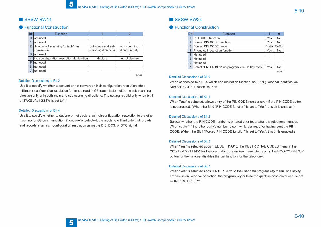
■ SSSW-SW14
● Functional ConstructionBit Function 1 00 not used - -1 not used - -2 direction of scanning for inch/mm
conversionboth main and sub scanning directions
sub scanning direction only
3 not used - -4 inch-configuration resolution declaration declare do not declare5 not used - -6 not used - -7 not used - -
Detailed Discussions of Bit 2Use it to specify whether to convert or not convert an inch-configuration resolution into a millimeter-configuration resolution for image read in G3 transmission: either in sub scanning direction only or in both main and sub scanning directions. The setting is valid only when bit 1 of SW05 of #1 SSSW is set to '1'.
Detailed Discussions of Bit 4Use it to specify whether to declare or not declare an inch-configuration resolution to the other machine for G3 communication: if 'declare' is selected, the machine will indicate that it reads and records at an inch-configuration resolution using the DIS, DCS, or DTC signal.
T-5-12
■ SSSW-SW24
● Functional ConstructionBit Function 1 00 PIN CODE function Yes No1 Forced PIN CODE function Yes No2 Forced PIN CODE mode Prefix Suffix3 Phone call restriction function Yes No4 Not used - -5 Not used - -6 Not used - -7 Select "ENTER KEY" on program Yes No key menu Yes No
Detailed Discussions of Bit 0When connected to a PBX which has restriction function, set "PIN (Personal Identification Number) CODE function" to "Yes".
Detailed Discussions of Bit 1When "Yes" is selected, allows entry of the PIN CODE number even if the PIN CODE button is not pressed. (When the Bit 0 "PIN CODE function" is set to "Yes", this bit is enables.)
Detailed Discussions of Bit 2Selects whether the PIN CODE number is entered prior to, or after the telephone number. When set to "1" the other party's number is sent while dialing, after having sent the PIN CODE. (When the Bit 1 "Forced PIN CODE function" is set to "Yes", this bit is enabled.)
Detailed Discussions of Bit 3When "Yes" is selected adds "TEL SETTING" to the RESTRICTIVE CODES menu in the "SYSTEM SETTING" for the user data program key menu. Depressing the HOOK/OFFHOOK button for the handset disables the call function for the telephone.
Detailed Discussions of Bit 7When "Yes" is selected adds "ENTER KEY" to the user data program key menu. To simplify Transmission Reserve operation, the program key outside the quick-release cover can be set as the "ENTER KEY".
T-5-13
5
5 Service Mode
Service Mode
5-11
5-11
Service Mode > Setting of Bit Switch (SSSW) > Bit Switch Composition > SSSW-SW26
Service Mode > Setting of Bit Switch (SSSW) > Bit Switch Composition > SSSW-SW26
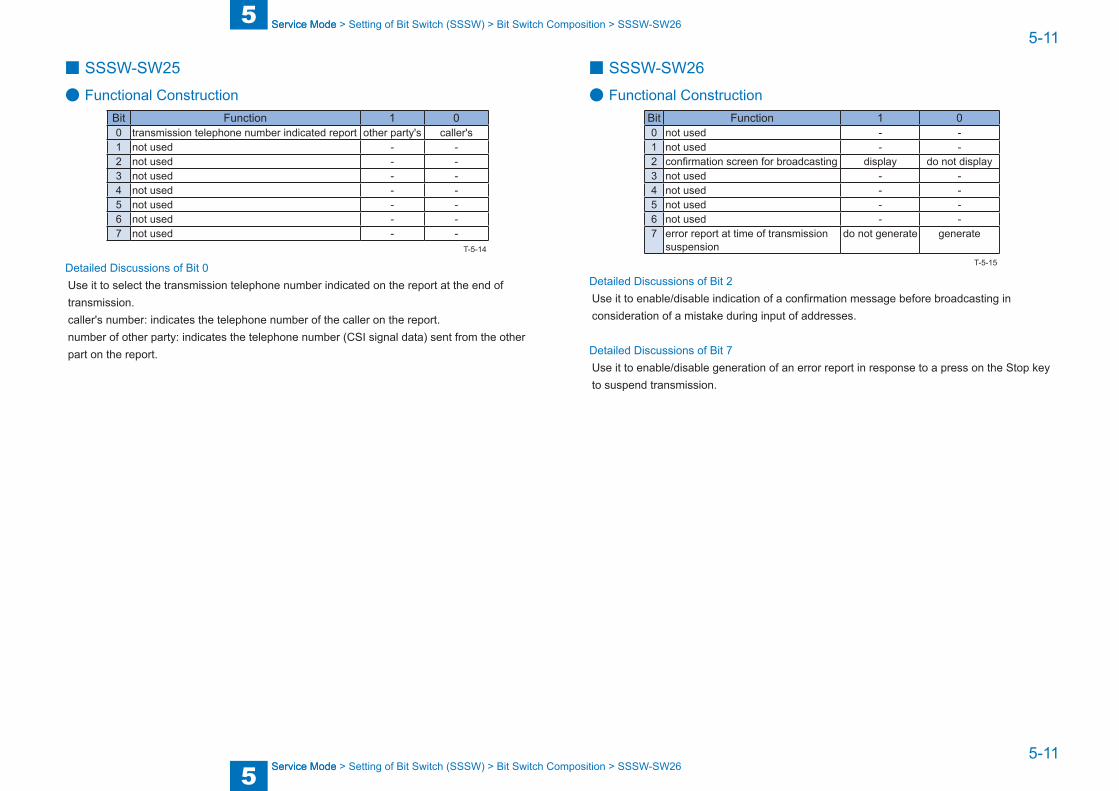
■ SSSW-SW25
● Functional ConstructionBit Function 1 00 transmission telephone number indicated report other party's caller's1 not used - -2 not used - -3 not used - -4 not used - -5 not used - -6 not used - -7 not used - -
Detailed Discussions of Bit 0Use it to select the transmission telephone number indicated on the report at the end of transmission.caller's number: indicates the telephone number of the caller on the report.number of other party: indicates the telephone number (CSI signal data) sent from the other part on the report.
T-5-14
■ SSSW-SW26
● Functional ConstructionBit Function 1 00 not used - -1 not used - -2 confirmation screen for broadcasting display do not display3 not used - -4 not used - -5 not used - -6 not used - -7 error report at time of transmission
suspensiondo not generate generate
Detailed Discussions of Bit 2Use it to enable/disable indication of a confirmation message before broadcasting in consideration of a mistake during input of addresses.
Detailed Discussions of Bit 7Use it to enable/disable generation of an error report in response to a press on the Stop key to suspend transmission.
T-5-15
5
5 Service Mode
Service Mode
5-12
5-12
Service Mode > Setting of Bit Switch (SSSW) > Bit Switch Composition > SSSW-SW28
Service Mode > Setting of Bit Switch (SSSW) > Bit Switch Composition > SSSW-SW28
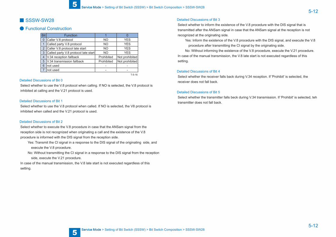
■ SSSW-SW28
● Functional ConstructionBit Function 1 00 Caller V.8 protocol NO YES1 Called party V.8 protocol NO YES2 Caller V.8 protocol late start NO YES3 Called party V.8 protocol late start NO YES4 V.34 reception fallback Prohibited Not prohibited5 V.34 transmission fallback Prohibited Not prohibited6 not used - -7 not used - -
Detailed Discussions of Bit 0Select whether to use the V.8 protocol when calling. If NO is selected, the V.8 protocol is inhibited at calling and the V.21 protocol is used.
Detailed Discussions of Bit 1Select whether to use the V.8 protocol when called. If NO is selected, the V8 protocol is inhibited when called and the V.21 protocol is used.
Detailed Discussions of Bit 2Select whether to execute the V.8 procedure in case that the ANSam signal from the reception side is not recognized when originating a call and the existence of the V.8 procedure is informed with the DIS signal from the reception side.
Yes: Transmit the CI signal in a response to the DIS signal of the originating side, and execute the V.8 procedure.
No: Without transmitting the CI signal in a response to the DIS signal from the reception side, execute the V.21 procedure.
In case of the manual transmission, the V.8 late start is not executed regardless of this setting.
T-5-16
Detailed Discussions of Bit 3Select whether to inform the existence of the V.8 procedure with the DIS signal that is transmitted after the ANSam signal in case that the ANSam signal at the reception is not recognized at the originating side.
Yes: Inform the existence of the V.8 procedure with the DIS signal, and execute the V.8 procedure after transmitting the CI signal by the originating side.
No: Without informing the existence of the V.8 procedure, execute the V.21 procedure.In case of the manual transmission, the V.8 late start is not executed regardless of this setting.
Detailed Discussions of Bit 4Select whether the receiver falls back during V.34 reception. If 'Prohibit' is selected, the receiver does not fall back.
Detailed Discussions of Bit 5Select whether the transmitter falls beck during V.34 transmission. If 'Prohibit' is selected, teh transmitter does not fall back.
5
5 Service Mode
Service Mode
5-13
5-13
Service Mode > Setting of Bit Switch (SSSW) > Bit Switch Composition > SSSW-SW30
Service Mode > Setting of Bit Switch (SSSW) > Bit Switch Composition > SSSW-SW30
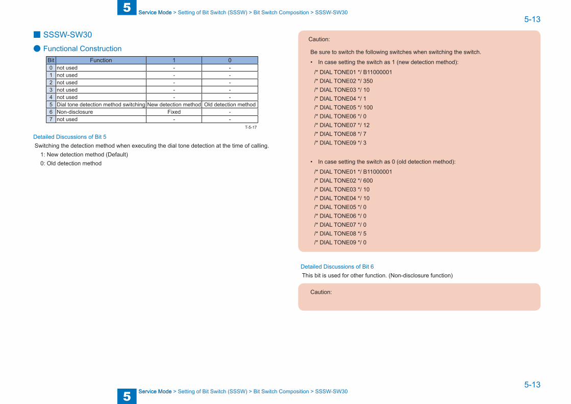
■ SSSW-SW30
● Functional ConstructionBit Function 1 00 not used - -1 not used - -2 not used - -3 not used - -4 not used - -5 Dial tone detection method switching New detection method Old detection method6 Non-disclosure Fixed -7 not used - -
Detailed Discussions of Bit 5Switching the detection method when executing the dial tone detection at the time of calling.
1: New detection method (Default) 0: Old detection method
T-5-17
Caution:
Be sure to switch the following switches when switching the switch.
• In case setting the switch as 1 (new detection method):
/* DIAL TONE01 */ B11000001/* DIAL TONE02 */ 350/* DIAL TONE03 */ 10/* DIAL TONE04 */ 1/* DIAL TONE05 */ 100/* DIAL TONE06 */ 0/* DIAL TONE07 */ 12/* DIAL TONE08 */ 7/* DIAL TONE09 */ 3
• In case setting the switch as 0 (old detection method):
/* DIAL TONE01 */ B11000001/* DIAL TONE02 */ 600/* DIAL TONE03 */ 10/* DIAL TONE04 */ 10/* DIAL TONE05 */ 0/* DIAL TONE06 */ 0/* DIAL TONE07 */ 0/* DIAL TONE08 */ 5/* DIAL TONE09 */ 0
Detailed Discussions of Bit 6This bit is used for other function. (Non-disclosure function)
Caution:

5
5 Service Mode
Service Mode
5-14
5-14
Service Mode > Setting of Menu Switch (MENU) > Menu Switch Composition
Service Mode > Setting of Menu Switch (MENU) > Menu Switch Composition
Setting of Menu Switch (MENU)
Menu Switch Composition
<1/3> <READY>
ReportSssw Menu Num Ncu Type ISDN Print Clear Test
OK
001
002
003004
005
006
007
008
xxxxx
xxxxx
xxxxx
xxxxx
xxxxx
xxxxx
xxxxx
xxxxx
←(yyyyy){aaaaa~bbbbb}
←(yyyyy){aaaaa~bbbbb}
←(yyyyy){aaaaa~bbbbb}←(yyyyy){aaaaa~bbbbb}
←(yyyyy){aaaaa~bbbbb}
←(yyyyy){aaaaa~bbbbb}
←(yyyyy){aaaaa~bbbbb}
←(yyyyy){aaaaa~bbbbb}
No. Function Range of settings005 NL equalizer 1: ON, 0: OFF006 telephone line monitor from 0 to 3007 transmission level (ATT) from 8 to 15 (ex: 15= -15 dBm)008 V.34 modulation speed upper limit 0:3429, 1:3200, 2:3000, 3:2800, 4:2743, 5:2400009 V34 data speed upper limit from 0 to 13
<005: NL Equalizer>Use it to enable-disable the NL equalizer.If errors occur often during communication because of the condition of the line, enable (ON) the NL equalizer.
Error Code:Any of the following error codes may be indicated at time of transmission because of the line condition##100, ##101, ##102, ##104, ##201, ##281, ##282, ##283, ##750, ##755, ##765, ##774, ##779, ##784, ##789
Any of the following error codes may be indicated at time of transmission because of the line condition##103, ##107, ##114, ##201, ##790, ##793
F-5-11
T-5-18
<006: Telephone Line Monitor>Use it to the telephone line monitor function:
0(DIAL): generate the monitor sound of the telephone line using the speaker from the start of transmission to DIS.
1: generate the monitor sound of the telephone line using the speaker from the start of communication to the end of it.
2: not used3(OFF): do not generate the monitor sound of the telephone line usng the speaker.
<007: ATT Transmission Level>Use it to set the transmission level (ATT).Raise the transmission level if errors occur frequently at time of communication because of the condition of the line. (It means close to 8)
Error Code:Any of the following error codes may be indicated at time of transmission because of the line condition##100, ##101, ##102, ##104, ##201, ##280, ##281, ##282, ##283, ##284, ##750, ##752, ##754, ##755, ##757, ##759, ##760, ##762, ##764, ##765, ##767, ##769, ##770, ##772, ##774, ##775, ##777, ##779, ##780, ##782, ##784, ##785, ##787, ##789
Any of the following error codes may be indicated at time of reception because of the line condition##103, ##106, ##107, ##201, ##793
<008: V.34 Modulation Speed Upper Limit>Use it to set an upper limit to the modulation speed (baud rate) for the V.34 primary channel.When '4 (2743 baud)' is selected, the actual communication is executed with 2400 baud.
<009: V.34 Data Speed Upper Limit>Use to set an upper limit to the data transmission speed for the V.34 primary channel between 2.4K and 33.6K bps in increments of 2400 bps. (0: 2.4K to 13: 33.6K bps).

5
5 Service Mode
Service Mode
5-15
5-15
Service Mode > Setting of Numeric Parameter (NUMERIC Param.) > Numerical Parameter Composition
Service Mode > Setting of Numeric Parameter (NUMERIC Param.) > Numerical Parameter Composition
Setting of Numeric Parameter (NUMERIC Param.)
Numerical Parameter Composition
<1/10> <READY>
ReportSssw Menu Num Ncu Type ISDN Print Clear Test
OK
001
002
003004
005
006
007
008
xxxxx
xxxxx
xxxxx
xxxxx
xxxxx
xxxxx
xxxxx
xxxxx
←(yyyyy){aaaaa~bbbbb}
←(yyyyy){aaaaa~bbbbb}
←(yyyyy){aaaaa~bbbbb}←(yyyyy){aaaaa~bbbbb}
←(yyyyy){aaaaa~bbbbb}
←(yyyyy){aaaaa~bbbbb}
←(yyyyy){aaaaa~bbbbb}
←(yyyyy){aaaaa~bbbbb}
No. Function Range of settings Initial setting002 RTN transmission condition (1) 1% to 99% 10003 RTN transmission condition (2) 2 to 99 times 15004 RTN transmission condition (3) 1 to 99 lines 12005 NCC pause time (before ID code) 1 to 60 sec 4006 NCC pause time (after ID code) 1 to 60 sec 4007 pre-pause time at time of placing call 0 to 9999 (x10 ms) 0009 number of characters in telephone numbers
between transmitting and receiving parties0 to 20 characters 0
010 line connection identification time 0 to 9999 (x10 ms) 5500011 T.30 T1 timer (for reception) 0 to 9999 (x10 ms) 3500013 T30. EOL timer 500 to 3000 (x10 ms) 1300027 preamble detection time for V21 low-speed flag 20 (x 10 ms) 0
F-5-12
T-5-19
<002: RTN transmission condition (1)><003: RTN transmission condition (2)><004: RTN transmission condition (3)>
Use it to set RTN signal transmission conditions. Raise these parameters for more lenient conditions if errors occur frequently at time of reception because of transmission of the RTN signal.
Error Code:Any of the following error codes may be indicated at time of reception because of RTN signal transmission##104, ##107, ##114, ##201
MEMO:RTN signal transmission condition (1) affects the ratio of error lines to the total number of lines per single page of received images.RTN signal transmission condition (2) affects the standard value (*2) of burst errors (*1).RTN signal condition (3) affects the number of errors not reaching the standard value of burst errors.*1: transmission error occurring cover several lines.*2: for instance, if '15' is set, a single burst error will represent an error occurring continuously cover 15 lines.
If any of these lines is detected while an image signal is being received, the RTN signal will be transmitted after receiving the protocol signal of the transmitting party. Higher parameters restrict the transmission of the RTN signal.
<005: NCC pause length (pre-ID code)>Use it to set the length of the pause automatically entered between access code and ID code when the NCC (New Common Carrier) line is used for dialing.
<006: NCC pause length (post-ID code)>Use it to set the length of the pause automatically entered between ID code and telephone number of the other party when the NCC (New Common Carrier) line is used for dialing.
<007: pre-pause length at time of ring>Use it to set the length of the pause used when placing a call.
<009: number of comparison digits of source telephone number and target telephone number>
Use it to set the number of TSI comparison characters (lower $ characters) for a check on telephone numbers.
5
5 Service Mode
Service Mode
5-16
5-16
Service Mode > Setting of Destination (TYPE) > Overview
Service Mode > Setting of Destination (TYPE) > Overview
<010: line connection identification length>Use it to set the time for identifying the line connection.Raise this parameter if errors occur frequently at time of communication because of the condition of the line.
Error Code:Any of the following error codes may be indicated because of the condition of the line##005, ##018
MEMO:The line condition identification time is between when the dial signal is transmitted and when the line condition is cut for the transmitting party, while it is between when the DIS
<011: T.30 T1 timer (for reception)>Set the T1 timer at the time of reception (the waiting time till receiving the significant signal after the DIS transmission).
Setting of Destination (TYPE)
OverviewWhen the type shown on the display is set, all the service data is set to match each country domestic telecommunication standards.

5
5 Service Mode
Service Mode
5-17
5-17
Service Mode > Setting of Printer Functions (PRINTER) > Setting of Bit Switch (SSSW) > SSSW-SW06
Service Mode > Setting of Printer Functions (PRINTER) > Setting of Bit Switch (SSSW) > SSSW-SW06
Setting of Printer Functions (PRINTER)
Setting of Bit Switch (SSSW) ■ SSSW-SW05
● Functional ConstructionBit Function 1 00 priority on LTR place do not place1 priority on LGL place do not place2 not used - -3 not used - -4 not used - -5 not used - -6 not used - -7 priority on recording in sub scanning
directionplace do not place
Detailed Discussions of Bits 0 and 1Use it to enable/disable placement of priority on LTR paper when an image that may be printed at 100% or in even division on A4, LTR, or LGL is received.The setting of bit 0 and bit 1 affects the order of priority as follows:
Bit1 Bit0 Priority of recording paper0 0 A4 -> LTR -> LGL0 1 LTR -> A4 -> LGL1 0 LGL -> LTR -> A41 1 LTR -> LGL -> A4
However, when priority is on recording in sub scanning direction, the order will be as follows even when bit 1 and bit 0 are set to '0': LTR -> A4 -> LGL.
Detailed Discussions of Bit 7Use it to enable/disable placement of priority on recording in sub scanning direction.
place: if B4 recording paper and A4 recording paper are set and an A4 extra-long image (*) is received, printing will be on the B4 recording paper.
do not place: if B5 horizontal recording paper and A4 recording paper are set and a B4 image is received, printing will be by division and on B5 horizontal recording paper.
*: Image B4 or shorter and that cannot be printed by division and on A4 recording paper.
T-5-20
T-5-21
■ SSSW-SW06
● Functional ConstructionBit Function 1 00 not used - -1 not used - -2 not used - -3 not used - -4 not used - -5 reduced printing from A4 to B5 enable disable6 not used - -7 not used - -
Detailed Discussions of Bit 5Set whether to execute the reduction print that forcibly reduces the A4 size document into the B5 size. This function is invalid when outputting the report.
T-5-22
5
5 Service Mode
Service Mode
5-18
5-18
Service Mode > Setting of Printer Functions (PRINTER) > Setting of Numeric Parameter (NUMERIC Param.) > Numerical Parameter Composition
Service Mode > Setting of Printer Functions (PRINTER) > Setting of Numeric Parameter (NUMERIC Param.) > Numerical Parameter Composition
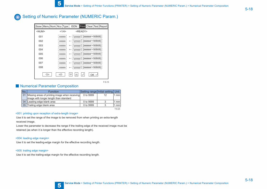
Setting of Numeric Parameter (NUMERIC Param.)
<1/4><NUM> <READY>
ReportSssw Menu Num Ncu Type ISDN Print Clear Test
OK
001
002
003004
005
006
007
008
xxxxx
xxxxx
xxxxx
xxxxx
xxxxx
xxxxx
xxxxx
xxxxx
←(yyyyy){aaaaa~bbbbb}
←(yyyyy){aaaaa~bbbbb}
←(yyyyy){aaaaa~bbbbb}←(yyyyy){aaaaa~bbbbb}
←(yyyyy){aaaaa~bbbbb}
←(yyyyy){aaaaa~bbbbb}
←(yyyyy){aaaaa~bbbbb}
←(yyyyy){aaaaa~bbbbb}
■ Numerical Parameter CompositionNo. Function Setting range Initial setting Unit01 Missing areas of printing image when receiving
image with longer length than standard0 to 9999 12 1 mm
04 Leading edge blank area 0 to 9999 3 1 mm05 Trailing edge blank area 0 to 9999 3 1 mm
<001: printing upon reception of extra-length image>Use it to set the range of the image to be removed from when printing an extra-length received image.Lower the parameter to decrease the range if the trailing edge of the received image must be retained (as when it is longer than the effective recording length).
<004: leading edge margin>Use it to set the leading-edge margin for the effective recording length.
<005: trailing edge margin>Use it to set the trailing-edge margin for the effective recording length.
F-5-13
T-5-23

5
5 Service Mode
Service Mode
5-19
5-19
Service Mode > Initialization of Set Value (CLEAR) > Overview
Service Mode > Initialization of Set Value (CLEAR) > Overview
Initialization of Set Value (CLEAR)
OverviewYou can select and initialize data by making the following selections; as a result, settings and various parameter values will be reset to the factory settings.
Item Data to be initializedTEL telephone number registration data (*1)USSW SW user data and data registered under Service Mode #1 through #3.
of user data, the memory management data will not be deleted.image data collected in memory will not be deleted.
SRV SW user data and data in Service Mode #1 through #3, #7.NCU data under Service Mode #4.SRV DATA system dump list data.REPORT communication control report data.ALL all settings/registered data (*1) except data under Service Mode #5 TYPE (*2).COUNTER number of prints, number of sheets read.
*1: If the model is capable of storing addresses other than fax addresses, the telephone number data will not be deleted upon execution of 'TEL' and 'ALL'.To remove the telephone number data, use the host machine's service mode: COPIER > FUNCTION > CLEAR > ADRS-BK.
*2: When 'ALL' is executed, the values suited to the destination of the machine will be stored under 'TYPE'; in the case of Japan, 'standard'.
T-5-24

5
5 Service Mode
Service Mode
5-20
5-20
Service Mode > Test Mode (TEST) > Outline > Test Mode Construction
Service Mode > Test Mode (TEST) > Outline > Test Mode Construction
Test Mode (TEST)
Outline ■ Test Mode Construction
ReportSssw Menu Num Ncu Type ISDN Print Clear Test
MODEM
FACULTY
DATA SET
ISDNMOD
ISDNMOD2
<Using Test Mode>
1) Press the desired item to highlight; then, press the OK key to bring up its screen.
F-5-14
The following table shows text mode items that are valid and invalid when a fax board is installed:
yes: may be used-: not used
Level 1 Level 2 Fax Board presentMODEM RELAY-1 yes
RELAY-2 -FREQ yesG3TX yes
DTMFTX yesTONERX -V34G3TX yes
FACULTY G3 4800TX yesSPEAKER -DETECT1 -DETECT2 -DETECT3 -VOICETX -
DATA SET -ISDNMOD -ISDNMOD2 -
Caution:
T-5-25
5
5 Service Mode
Service Mode
5-21
5-21
Service Mode > Test Mode (TEST) > MODEM Test > Frequency Test (FREQ)
Service Mode > Test Mode (TEST) > MODEM Test > Frequency Test (FREQ)
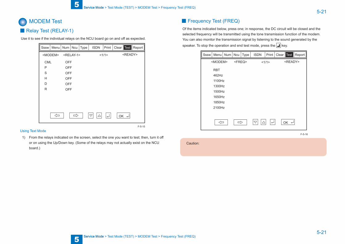
MODEM Test ■ Relay Test (RELAY-1)
Use it to see if the individual relays on the NCU board go on and off as expected.
<1/1><MODEM> <READY>
ReportSssw Menu Num Ncu Type ISDN Print Clear Test
CMLPSHDR
<RELAY-1>
OFFOFFOFFOFFOFFOFF
OK
Using Text Mode
1) From the relays indicated on the screen, select the one you want to test; then, turn it off or on using the Up/Down key. (Some of the relays may not actually exist on the NCU board.)
F-5-15
■ Frequency Test (FREQ)Of the items indicated below, press one; in response, the DC circuit will be closed and the selected frequency will be transmitted using the tone transmission function of the modem. You can also monitor the transmission signal by listening to the sound generated by the
speaker. To stop the operation and end test mode, press the key.
<1/1> <READY>
ReportSssw Menu Num Ncu Type ISDN Print Clear Test
<FREQ><MODEM>
OK
RBT462Hz1100Hz1300Hz1500Hz1650Hz1850Hz2100Hz
Caution:
F-5-16

5
5 Service Mode
Service Mode
5-22
5-22
Service Mode > Test Mode (TEST) > MODEM Test > G3 Signal Transmission Test (G3 Tx)
Service Mode > Test Mode (TEST) > MODEM Test > G3 Signal Transmission Test (G3 Tx)
■ G3 Signal Transmission Test (G3 Tx)Of the items indicated below, press one. In response, the DC circuit will be closed and the selected frequency will be transmitted using the G3 signal transmission function of the modem. You can also monitor the transmission signal by listening to the sound generated by
the speaker. To stop the operation and end test mode, press the key.
<1/2> <READY>
ReportSssw Menu Num Ncu Type ISDN Print Clear Test
<G3TX><MODEM>
OK
300bps2400bps4800bps7200bps9600bpsTC7200TC960012000bps
<2/2> <READY>
ReportSssw Menu Num Ncu Type ISDN Print Clear Test
<G3TX><MODEM>
OK
14400bps300-ALL0300-ALL1300-1:1300-1:4300-4:1
F-5-17
F-5-18
Caution:

5
5 Service Mode
Service Mode
5-23
5-23
Service Mode > Test Mode (TEST) > MODEM Test > V.34 G3 Signal Transmission Test (V34G3Tx)
Service Mode > Test Mode (TEST) > MODEM Test > V.34 G3 Signal Transmission Test (V34G3Tx)
■ DTMF Transmission TestOf the items indicated below, press one; in response, the DC circuit will be closed and the selected DTMF signal will be transmitted using the DTMF transmission function of the modem. You can also monitor the transmission signal by listening to the speaker. To stop the
operation and to end test mode, press the key.
<1/1> <READY>
ReportSssw Menu Num Ncu Type ISDN Print Clear Test
<DTMFTX><MODEM>
OK
LONGSHORT
0 1 2 3 4 5 6 7 8 9 * #0 1 2 3 4 5 6 7 8 9 * #
Using Text Mode
1) From the items indicated on the screen, select the item you want to test; then, press the key on keypad that corresponds to the DTMF signal to test.
Caution:
F-5-19
■ V.34 G3 Signal Transmission Test (V34G3Tx)Select the transmission speed you want to test, and then select a modulation speed (baud rate); in response, the V.34 G3 transmission signal will be transmitted to the telephone line
terminal and the speaker. To stop the operation and to end test mode, press the key.
<1/1> <READY>
ReportSssw Menu Num Ncu Type ISDN Print Clear Test
<V34G3TX><MODEM>
OK
SPEED 33600bps3429baud3200baud3000baud2800baud2743baud2400baud
Using Text Mode
1) Select 'SPEED', and then select the speed you want to test using the Up/Down key.
2) Select the baud rate you want to test.
F-5-20
5
5 Service Mode
Service Mode
5-24
5-24
Service Mode > Test Mode (TEST) > Function Test > 4800-bps Signal Transmission Test
Service Mode > Test Mode (TEST) > Function Test > 4800-bps Signal Transmission Test
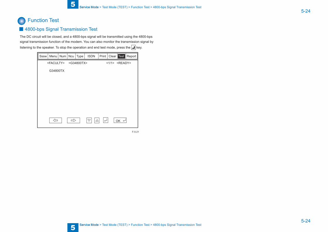
Function Test ■ 4800-bps Signal Transmission Test
The DC circuit will be closed, and a 4800-bps signal will be transmitted using the 4800-bps signal transmission function of the modem. You can also monitor the transmission signal by
listening to the speaker. To stop the operation and end test mode, press the key.
<READY><1/1>
ReportSssw Menu Num Ncu Type ISDN Print Clear Test
<FACULTY> <G34800TX>
OK
G34800TX
F-5-21

5
5 Service Mode
Service Mode
5-25
5-25
Service Mode > Service Report (REPORT) > System Dump List
Service Mode > Service Report (REPORT) > System Dump List
Service Report (REPORT)
System Data ListUse it to check the settings associated with the service soft switch and service parameters.
SERIAL NO XXXXXXXX
#1 SSSW SW01 ----- 00000000 SW02 ----- 10000000 SW03 ----- 00000000 SW04 ----- 10000000 SW05 ----- 00000000 SW06 ----- 10000000 SW07 ----- 00000000 SW08 ----- 00000000 SW09 ----- 00000000 SW10 ----- 00000000 SW11 ----- 00000000 SW12 ----- 00000011 SW13 ----- 00000000 SW14 ----- 00000000 SW15 ----- 00000000 SW16 ----- 00000000 SW17 ----- 00000000 SW18 ----- 00000000 SW19 ----- 00011000 SW20 ----- 00000000 SW21 ----- 00000000 SW22 ----- 00000000 SW23 ----- 00000000 SW24 ----- 00000000 SW25 ----- 00000000 SW26 ----- 00100000 SW27 ----- 00000000 SW28 ----- 00000000 SW29 ----- 00000000 SW30 ----- 00000000 SW31 ----- 00000000 SW32 ----- 00000000 SW33 ----- 00000000 SW34 ----- 00000000 SW35 ----- 00000000 SW36 ----- 00000000 SW37 ----- 00000000 SW38 ----- 00000000 SW39 ----- 00000000 SW40 ----- 00000000 SW41 ----- 00000000 SW42 ----- 00000000 SW43 ----- 00000000 SW44 ----- 00000000 SW45 ----- 00000000 SW46 ----- 00000000 SW47 ----- 00000000 SW48 ----- 00000000 SW49 ----- 00000000 SW50 ----- 00000000
#2 MENU 01: ----- 0 02: ----- 0 03: ----- 0 04: ----- 0 05: ----- 0 06: ----- 0 07: ----- 10 08: ----- 0 09: ----- 0 10: ----- 2
********************************* SYSTEM DATA LIST *********************************
2003 09/02 TUE 12:00 FAX 001
F-5-22
System Dump List
MEMO:A system dump list is generated when you execute the following in service mode: FAX
Use it to check the history of communications, both successful and error.
SERIAL NO XXXXXXXX
CLEAR DATE 2003 09/02 TUE 11:00 TX = 1298A4 = 1302 B4 = 49 A3 = 27 LTR = 0 LGL = 0RX = 1572A4 = 1581 B4 = 59 A3 = 59 LTR = 0 LGL = 033600 = 1 31200 = 0 28800 = 2986 26400 = 0 24000 = 021600 = 0 19200 = 0 16800 = 0 14400 = 0 12000 = 09600 = 0 7200 = 0 4800 = 0 2400 = 014400 = 83 12000 = 1 TC9600 = 0 TC7200 = 014400 = 0 14400 = 09600 = 2 7200 = 0 4800 = 4 2400 = 0STD = 60 FINE = 2839 SUPER = 107 ULTRA = 71MH = 7 MR = 32 MMR = 9 JBIG = 3029 JPEG = 0G3 = 37 ECM = 3040 G4 = 0
********************************** SYSTEM DUMP LIST **********************************
2003 09/02 TUE 12:00 FAX 001
#000 0 0 0 0 0 0 0 0 0 0 0 0 0 0 0 0 0 0 2 0 0 0 0 0 0 0 0 0 0 0 0 0 0 0 0 0 0 0 0 0 0 0 0 0 0 0 0 0 0 0 0 0 0 0 0 0 0 0 0 0 0 0 0 0 0 0 0 0 0 0 0 0 0 0 0 0 0 0 0 0 0 0 0 0 0 0 0 0 0 0 0 22 0 0 0 0 0 0 0 0 0 0 0 0
#100 0 0 0 0 0 0 18 0 0 0 0 0 0 0 0 0 0
#200 0 50 0 0 0 0
*1*2*1*2*3
*4*5*6
*7
*1: RX, total reception number of times; TX, total transmission number of times.*2: number of pages sent/received according to original size.*3: number of pages sent/received in connection with different modem speeds (Standard,
Fine, Super Fine, Ultra Fine).*4: number of pages sent/received in connection with different modes.*5: number of pages sent/received in connection with different coding methods.*6: number of transmissions/receptions according to mode.*7: number of occurrences according to error code.
Indication sample
#280 1 7 3 0 0 ↑ ↑ ↑ number of errors ##280 number of errors ##281 number of errors ##282
F-5-23
F-5-24

5
5 Service Mode
Service Mode
5-26
5-26
Service Mode > Service Report (REPORT) > Error Transmission Report
Service Mode > Service Report (REPORT) > Error Transmission Report
It provides error information on the 3 most recent communications.
*1*2
*8
*3*4*5
*6*7
2003 09/02 TUE 12:00 FAX
#1 LATEST #000
START TIME 09/02 10:00 OTHER PARTY 12345678 MAKER CODE 10001000 MACHINE CODE 0100001 00000000 RCV V.8 FRAME E0 81 85 D4 90 7E 00 00 SYMBOL RATE 3429 baud DATA RATE 28800 bps [V. 34] TX LVL REDUCTION 0 ERR ABCODE 00 ERR SECTXB 00 ERR SECRXB 00
Rx : ( bit 1 ) 00000100 01110111 01011111 00100011 00000001 10101001 00000001 ( bit 56 ) ( bit 57 ) 00000001 00000001 00000100 00000000 00000000 ( bit 96 ) Tx : ( bit 1 ) 00000000 01000010 00011111 00100001 00000001 00000001 00000001 ( bit 56 ) ( bit 57 ) 00000001 00000001 00000100 00000000 00000000 ( bit 96 )
001
Rx : NSF CSI DIS CFR MCF MCF
Tx : NSS TSI DCS PIX-288 PPS-NUL PIX-288 PPS-NUL PIX-288 PPS-NUL
Rx : MCF MCF MCF
Tx : PIX-288 PPS-NUL PIX-288 PPS-EOP DCN
#2 #000
START TIME 09/02 09:30 OTHER PARTY 12345678 MAKER CODE 10001000 MACHINE CODE 0100001 00000000 RCV V.8 FRAME E0 81 85 D4 90 7E 00 00 SYMBOL RATE 3429 baud DATA RATE 28800 bps [V. 34] TX LVL REDUCTION 0 ERR ABCODE 00 ERR SECTXB 00 ERR SECRXB 00
Rx : ( bit 1 ) 00000100 01110111 01011111 00100011 00000001 10101001 00000001 ( bit 56 ) ( bit 57 ) 00000001 00000001 00000100 00000000 00000000 ( bit 96 ) Tx : ( bit 1 ) 00000000 01000010 00011111 00100001 00000001 00000001 00000001 ( bit 56 ) ( bit 57 ) 00000001 00000001 00000100 00000000 00000000 ( bit 96 )
Rx : NSF CSI DIS CFR MCF MCF
Tx : NSS TSI DCS PIX-288 PPS-NUL PIX-288 PPS-NUL PIX-288 PPS-NUL
Rx : MCF MCF MCF
Tx : PIX-288 PPS-NUL PIX-288 PPS-EOP DCN
#3 OLDEST #000
START TIME 09/02 09:00 OTHER PARTY 12345678 MAKER CODE 10001000 MACHINE CODE 0100001 00000000 RCV V.8 FRAME E0 81 85 D4 90 7E 00 00 SYMBOL RATE 3429 baud DATA RATE 28800 bps [V. 34] TX LVL REDUCTION 0 ERR ABCODE 00 ERR SECTXB 00 ERR SECRXB 00
*8
*1: service error code.*2: START TIME, date and time (in 24-hr notation).*3: OTHER PARTY, telephone number sent by the other party.*4: MAKER CODE, manufacturer code.*5: MACHINE CODE, model code.*6: bit 1 through bit 96 of DIS, DCS, or DTC that has been received.*7: bit 1 through bit 96 of DIS, DCS, or DTC that has been transmitted.*8: RX, procedural signal received; TX, procedural signal transmitted.
F-5-25
Error Transmission ReportAn error transmission report is an error transmission report together to which a service error code and error dump list is attached.
TX FUNCTION WAS NOT COMPLETED
JOB NO. 1269DESTINATION ADDRESS 12345678PSWD/SUBADDRESSDESTINATION IDST. TIME 09/02 09:00USAGE T 01 ' 50PGS. 1RESULT NG 1 ##750
********************************** FAX ERROR TX REPORT **********************************
2003 09/02 TUE 12:00 FAX 001
START TIME 09/02 09:00 OTHER PARTY 12345678 MAKER CODE 10001000 MACHINE CODE 0100001 00000000 RCV V.8 FRAME E0 81 85 D4 90 7E 00 00 SYMBOL RATE 3429 baud DATA RATE 28800 bps [V. 34] TX LVL REDUCTION 0 ERR ABCODE 92 ERR SECTXB 8A ERR SECRXB 80
Rx : ( bit 1 ) 00000100 01110111 01011111 00100011 00000001 10101001 00000001 ( bit 56 ) ( bit 57 ) 00000001 00000001 00000100 00000000 00000000 ( bit 96 ) Tx : ( bit 1 ) 00000000 01000010 00011111 00100001 00000001 00000001 00000001 ( bit 56 ) ( bit 57 ) 00000001 00000001 00000100 00000000 00000000 ( bit 96 )
Rx : NSF CSI DIS CFR MCF MCF
Tx : NSS TSI DCS PIX-288 PPS-NUL PIX-288 PPS-NUL PIX-288 PPS-NUL
Rx : MCF MCF MCF
Tx : PIX-288 PPS-NUL PIX-288 PPS-EOP DCN
F-5-26
6
6 InstallationInstallation
Installation ■How to Check this Installation Procedure ■Check Items when Turning OFF the Main Power ■Installation Outline Drawing ■Checking the Contents ■Installation Procedure ■Operation Setting

6
6 Installation
Installation
6-2
6-2
Installation > Installation Outline Drawing
Installation > Installation Outline Drawing
How to Check this Installation Procedure
When Using the Parts Included in the PackageA symbol is described on the illustration in the case of using the parts included in the package of this product.
Packaged Item
Symbols in the IllustrationThe frequently-performed operations are described with symbols in this procedure.
Connector
Disconnect
Screw
Tighten Remove Connect Secure Free
Harness
PushInsert Plug in Turn on
Sound CheckCheck Visual Check
Claw
Remove
Checking instruction
F-6-1
F-6-2
Check Items when Turning OFF the Main PowerCheck that the main power switch is OFF.1) Turn OFF the main power switch of the host machine.2) Be sure that Control Panel Display and Main Power Lamp are both turned OFF, and then disconnect the power plug.
Installation Outline Drawing
F-6-3
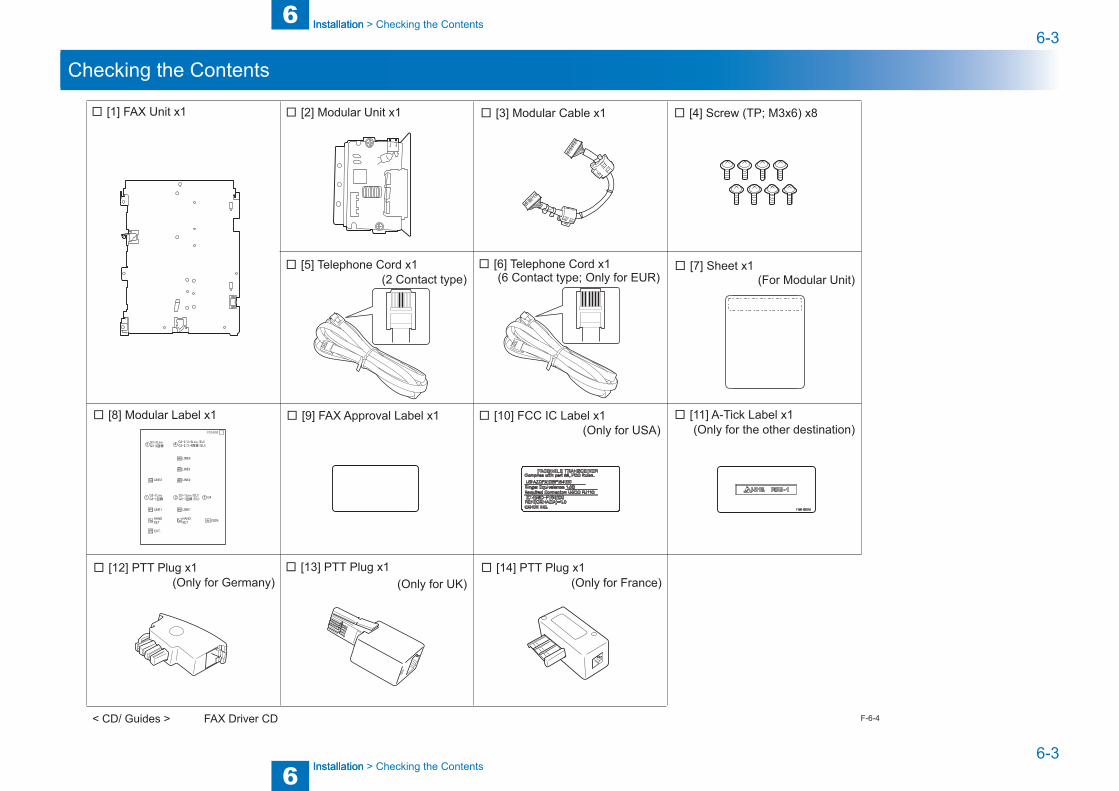
6
6 Installation
Installation
6-3
6-3
Installation > Checking the Contents
Installation > Checking the Contents
Checking the Contents
□ [1] FAX Unit x1 □ [2] Modular Unit x1 □ [3] Modular Cable x1 □ [4] Screw (TP; M3x6) x8
□ [8] Modular Label x1 □ [9] FAX Approval Label x1 □ [10] FCC IC Label x1
□ [5] Telephone Cord x1
□ [12] PTT Plug x1 □ [13] PTT Plug x1 □ [14] PTT Plug x1
□ [6] Telephone Cord x1 □ [7] Sheet x1
(Only for USA)
(2 Contact type) (6 Contact type; Only for EUR)
(Only for Germany) (Only for UK) (Only for France)
(For Modular Unit)
□ [11] A-Tick Label x1(Only for the other destination)
< CD/ Guides > FAX Driver CD F-6-4

6
6 Installation
Installation
6-4
6-4
Installation > Installation Procedure
Installation > Installation Procedure
Installation Procedure ■ Installing the Fax Board-AK1
1) Remove the Rear Cover.• 4 Screws, 4 Claws2) Remove the Left Rear Cover.• 4 Screws, 2 Claws
x4
x2
x4
x4F-6-5
3) Remove the Controller Box Cover.
4) Remove the Fax Unit Cover and install the Fax Unit.• 2 Claws, 4 Screws (TP)
x4
x2
F-6-6
F-6-7
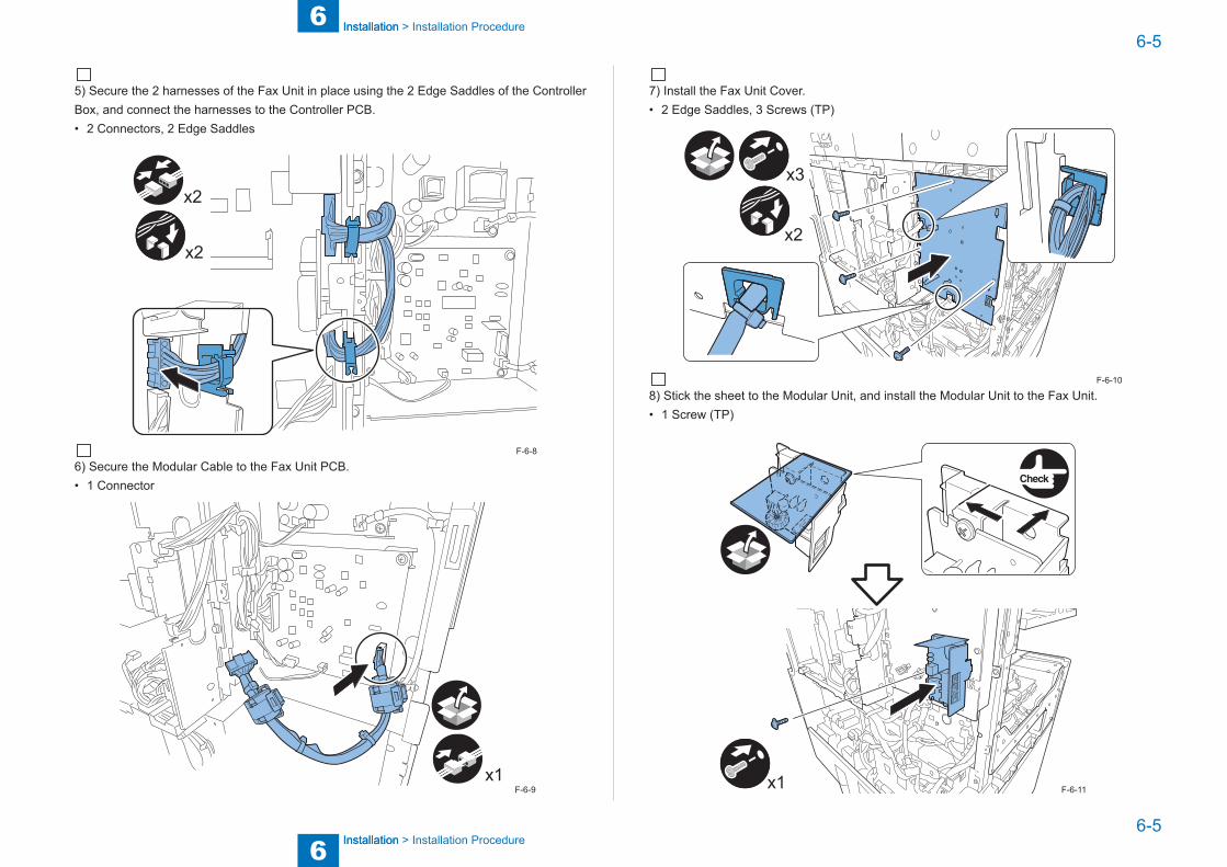
6
6 Installation
Installation
6-5
6-5
Installation > Installation Procedure
Installation > Installation Procedure
5) Secure the 2 harnesses of the Fax Unit in place using the 2 Edge Saddles of the Controller Box, and connect the harnesses to the Controller PCB.• 2 Connectors, 2 Edge Saddles
x2
x2
6) Secure the Modular Cable to the Fax Unit PCB.• 1 Connector
x1
F-6-8
F-6-9
7) Install the Fax Unit Cover.• 2 Edge Saddles, 3 Screws (TP)
x3
x2
8) Stick the sheet to the Modular Unit, and install the Modular Unit to the Fax Unit.• 1 Screw (TP)
x1
F-6-10
F-6-11
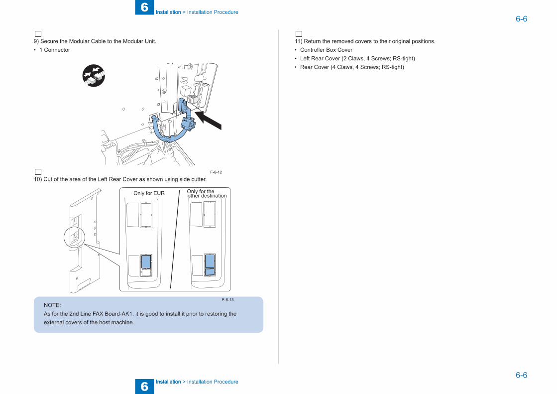
6
6 Installation
Installation
6-6
6-6
Installation > Installation Procedure
Installation > Installation Procedure
9) Secure the Modular Cable to the Modular Unit.• 1 Connector
10) Cut of the area of the Left Rear Cover as shown using side cutter.
Only for EUR Only for theother destination
NOTE:As for the 2nd Line FAX Board-AK1, it is good to install it prior to restoring the external covers of the host machine.
F-6-12
F-6-13
11) Return the removed covers to their original positions.• Controller Box Cover• Left Rear Cover (2 Claws, 4 Screws; RS-tight)• Rear Cover (4 Claws, 4 Screws; RS-tight)
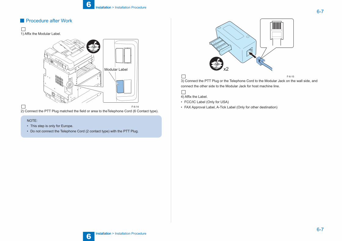
6
6 Installation
Installation
6-7
6-7
Installation > Installation Procedure
Installation > Installation Procedure
■ Procedure after Work
1) Affix the Modular Label.
Modular Label
2) Connect the PTT Plug matched the field or area to theTelephone Cord (6 Contact type).
NOTE:• This step is only for Europe.• Do not connect the Telephone Cord (2 contact type) with the PTT Plug.
F-6-14
x2
3) Connect the PTT Plug or the Telephone Cord to the Modular Jack on the wall side, and connect the other side to the Modular Jack for host machine line.
4) Affix the Label.• FCC/IC Label (Only for USA)• FAX Approval Label, A-Tick Label (Only for other destination)
F-6-15
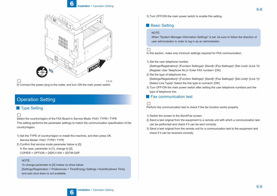
6
6 Installation
Installation
6-8
6-8
Installation > Operation Setting
Installation > Operation Setting
5) Connect the power plug to the outlet, and turn ON the main power switch.
Operation Setting ■ Type Setting
Select the country/region of the FAX Board in Service Mode: FAX> TYPE> TYPEThis setting performs the parameter settings to match the communication specification of the country/region.
1) Set the TYPE of country/region to install this machine, and then press OK. Service Mode> FAX> TYPE> TYPE2) Confirm that service mode parameter below is [0]. In the case, parameter is [1], change to [0]. COPIER > OPTION > DSPLY-SW > SDTM-DSP
NOTE:To change parameter to [0] makes no show below [Settings/Registration > Preferences > Time/Energy Settings >AutoShutdown Time] and auto shut down is not available.
F-6-16
3) Turn OFF/ON the main power switch to enable this setting.
■ Basic Setting
NOTE:When "System Manager Information Settings" is set, be sure to follow the direction of user administrator in order to log in as an administrator.
In this section, make only minimum settings required for FAX communication.
1) Set the user telephone number. [Settings/Registration]> [Function Settings]> [Send]> [Fax Settings]> [Set Line]> [Line 1]> [Register User Telephone No.]> Enter FAX number> [OK]2) Set the type of telephone line. [Settings/Registration]> [Function Settings]> [Send]> [Fax Settings]> [Set Line]> [Line 1]> [Select Line Type]> Select the line type to connect> [OK]3) Turn OFF/ON the main power switch after setting the user telephone numbers and the type of telephone line.
■ Fax communication test
Perform the communication test to check if the fax function works properly.
1) Switch the screen to the Send/Fax screen.2) Send a test original from the equipment to a remote unit with which a communication test can be performed and check if it can be sent correctly.3) Send a test original from the remote unit for a communication test to the equipment and check if it can be received correctly.