staple finisher-r1 service manual - canon...
TRANSCRIPT
654321
Staple Finisher-R1Service Manual
April 24, 2013Revision 0
0
00-2
0-2
ApplicationThis manual has been issued by Canon Inc. for qualified persons to learn technical theory, installation, maintenance, and repair of products. This manual covers all localities where the products are sold. For this reason, there may be information in this manual that does not apply to your locality.
CorrectionsThis manual may contain technical inaccuracies or typographical errors due to improvements or changes in products. When changes occur in applicable products or in the contents of this manual, Canon will release technical information as the need arises. In the event of major changes in the contents of this manual over a long or short period, Canon will issue a new edition of this manual.
The following paragraph does not apply to any countries where such provisions are inconsistent with local law.
TrademarksThe product names and company names used in this manual are the registered trademarks of the individual companies.
CopyrightThis manual is copyrighted with all rights reserved. Under the copyright laws, this manual may not be copied, reproduced or translated into another language, in whole or in part, without the consent of Canon Inc.
Coryright CANON INC. 2013
CautionUse of this manual should be strictly supervised to avoid disclosure of confidential information.
0
00-3
0-3
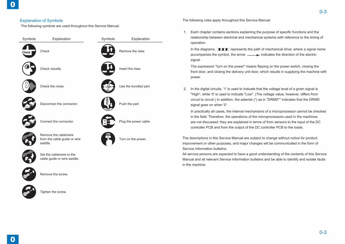
Explanation of SymbolsThe following symbols are used throughout this Service Manual.
Symbols Explanation Symbols Explanation
Check Remove the claw.
Check visually Insert the claw.
Check the noise. Use the bundled part.
Disconnect the connector. Push the part.
Connect the connector. Plug the power cable.
Remove the cable/wire from the cable guide or wire saddle.
Turn on the power.
Set the cable/wire to the cable guide or wire saddle.
Remove the screw.
Tighten the screw.
The following rules apply throughout this Service Manual:
1. Each chapter contains sections explaining the purpose of specific functions and the relationship between electrical and mechanical systems with reference to the timing of operation.
In the diagrams, represents the path of mechanical drive; where a signal name accompanies the symbol, the arrow indicates the direction of the electric signal.
The expression "turn on the power" means flipping on the power switch, closing the front door, and closing the delivery unit door, which results in supplying the machine with power.
2. In the digital circuits, '1' is used to indicate that the voltage level of a given signal is "High", while '0' is used to indicate "Low". (The voltage value, however, differs from circuit to circuit.) In addition, the asterisk (*) as in "DRMD*" indicates that the DRMD signal goes on when '0'.
In practically all cases, the internal mechanisms of a microprocessor cannot be checked in the field. Therefore, the operations of the microprocessors used in the machines are not discussed: they are explained in terms of from sensors to the input of the DC controller PCB and from the output of the DC controller PCB to the loads.
The descriptions in this Service Manual are subject to change without notice for product improvement or other purposes, and major changes will be communicated in the form of Service Information bulletins.All service persons are expected to have a good understanding of the contents of this Service Manual and all relevant Service Information bulletins and be able to identify and isolate faults in the machine.

Blank Page
0
00-5
0-5
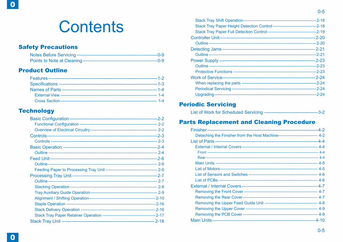
ContentsSafety Precautions
Notes Before Servicing ------------------------------------------------------0-9Points to Note at Cleaning --------------------------------------------------0-9
Product OutlineFeatures -------------------------------------------------------------------------1-2Specifications ------------------------------------------------------------------1-3Names of Parts ----------------------------------------------------------------1-4
External View ----------------------------------------------------------------------- 1-4Cross Section ----------------------------------------------------------------------- 1-4
TechnologyBasic Configuration -----------------------------------------------------------2-2
Functional Configuration --------------------------------------------------------- 2-2Overview of Electrical Circuitry ------------------------------------------------- 2-2
Controls --------------------------------------------------------------------------2-3Controls ------------------------------------------------------------------------------ 2-3
Basic Operation ---------------------------------------------------------------2-4Outline -------------------------------------------------------------------------------- 2-4
Feed Unit ------------------------------------------------------------------------2-6Outline -------------------------------------------------------------------------------- 2-6Feeding Paper to Processing Tray Unit -------------------------------------- 2-6
Processing Tray Unit ---------------------------------------------------------2-7Outline -------------------------------------------------------------------------------- 2-7Stacking Operation ---------------------------------------------------------------- 2-8Tray Auxiliary Guide Operation ------------------------------------------------- 2-9Alignment / Shifting Operation -------------------------------------------------2-10Staple Operation ------------------------------------------------------------------2-16Stack Delivery Operation -------------------------------------------------------2-16Stack Tray Paper Retainer Operation ---------------------------------------2-17
Stack Tray Unit -------------------------------------------------------------- 2-18
Stack Tray Shift Operation ------------------------------------------------------2-18Stack Tray Paper Height Detection Control --------------------------------2-18Stack Tray Paper Full Detection Control ------------------------------------2-19
Controller Unit ---------------------------------------------------------------- 2-20Outline -------------------------------------------------------------------------------2-20
Detecting Jams -------------------------------------------------------------- 2-21Outline -------------------------------------------------------------------------------2-21
Power Supply ---------------------------------------------------------------- 2-23Outline -------------------------------------------------------------------------------2-23Protective Functions -------------------------------------------------------------2-23
Work of Service -------------------------------------------------------------- 2-24When replacing the parts -------------------------------------------------------2-24Periodical Servicing --------------------------------------------------------------2-24Upgrading ---------------------------------------------------------------------------2-24
Periodic ServicingList of Work for Scheduled Servicing ------------------------------------3-2
Parts Replacement and Cleaning ProcedureFinisher --------------------------------------------------------------------------4-2
Detaching the Finisher from the Host Machine----------------------------- 4-2List of Parts ---------------------------------------------------------------------4-4
External / Internal Covers -------------------------------------------------------- 4-4Front ------------------------------------------------------------------------------------------- 4-4Rear -------------------------------------------------------------------------------------------- 4-4
Main Units --------------------------------------------------------------------------- 4-5List of Motors ------------------------------------------------------------------------ 4-5List of Sensors and Switches --------------------------------------------------- 4-6List of PCBs ------------------------------------------------------------------------- 4-6
External / Internal Covers ---------------------------------------------------4-7Removing the Front Cover ------------------------------------------------------ 4-7Removing the Rear Cover ------------------------------------------------------- 4-7Removing the Upper Feed Guide Unit --------------------------------------- 4-8Removing the Upper Cover ----------------------------------------------------- 4-9Removing the PCB Cover ------------------------------------------------------- 4-9
Main Units --------------------------------------------------------------------- 4-10

0
00-6
0-6
Removing the Grate-shaped Guide ------------------------------------------4-10Removing the Staple Unit ------------------------------------------------------- 4-11Removing the Upper Processing Tray Unit (Front / Rear) --------------4-12Removing the Lower Processing Tray Unit ---------------------------------4-15
Motors -------------------------------------------------------------------------- 4-16Removing the Feed Motor (M1) -----------------------------------------------4-16Removing the Delivery Motor (M2) -------------------------------------------4-17Removing the Paddle Motor (M3) --------------------------------------------4-18Removing the Front Alignment Motor (M4) ---------------------------------4-18Removing the Rear Alignment Motor (M5) ---------------------------------4-19Removing the Tray Auxiliary Guide Motor (M6) ---------------------------4-19Removing the Stack Tray Shift Motor (M8) ---------------------------------4-20
Switches ----------------------------------------------------------------------- 4-22Removing the Front Door Switch ---------------------------------------------4-22Removing the Stack Tray Lower Limit Switch -----------------------------4-23
PCBs --------------------------------------------------------------------------- 4-24Removing the Finisher Controller PCB --------------------------------------4-24
AdjustmentAdjustment Item ---------------------------------------------------------------5-2
Overview ----------------------------------------------------------------------------- 5-2Dip Switch Function ----------------------------------------------------------5-3
Sensor Detection Check Mode ------------------------------------------------- 5-3Entering the Sensor Detection Check Mode ----------------------------------------- 5-3List of Sensor Detection Check States ------------------------------------------------ 5-3
Motor Operation Check Mode -------------------------------------------------- 5-4Entering the Motor Operation Check Mode ------------------------------------------ 5-4List of Motor Operation Check States ------------------------------------------------- 5-4
Shifting Operation ON/OFF Setting in Staple Mode ---------------------- 5-5Tray Auxiliary Guide Operation ON/OFF Setting when delivering a sheet of paper ------------------------------------------------------------------------------- 5-5
InstallationHow to Utilize This Installation Procedure ------------------------------6-2
Descriptions Used in This Procedure ----------------------------------------- 6-2When Using the Contained Parts (Bundled Components in the Shipping
Carton) -------------------------------------------------------------------------------- 6-2Symbols in the Illustration ------------------------------------------------------- 6-2
Unpacking Procedure --------------------------------------------------------6-3Unpacking Procedure ------------------------------------------------------------- 6-3
Installation Procedure --------------------------------------------------------6-4Preparation for Installation on Host Machine ------------------------------- 6-4Connecting to Host Machine ---------------------------------------------------- 6-5
AppendixService Tools -------------------------------------------------------------------7-2
Solvents and Oils ------------------------------------------------------------------ 7-2Applying the Grease ----------------------------------------------------------------------- 7-3
Special Tools ------------------------------------------------------------------------ 7-5General Circuit Diagram -----------------------------------------------------7-6
General Circuit Diagram --------------------------------------------------------- 7-6

Safety Precautions ■Notes Before Servicing ■Points to Note at Cleaning
0
00-8
0-8
Safety Precautions > Points to Note at Cleaning
Safety Precautions > Points to Note at Cleaning
Notes Before Servicing
Caution:
At servicing, be sure to turn off the power source according to the specified steps and disconnect the power plug.
Caution:
Do not turn off the power switch when downloading is under way.
Turning off the main power switch while downloading is under way can disable the machine.
Points to Note at Cleaning
Caution:
When performing cleaning using organic solvent such as alcohol, be sure to check that the component of solvent is vaporized completely before assembling.

1
1 Product Outline
Product Outline ■Features ■Specifications ■Names of Parts

1
11-2
1-2
Product Outline > Features
Product Outline > Features
Features
• Compact, semi-inner finisher which corresponds to A4 black-and-white, high-speed MFP.
• Gripper mechanism for delivering paper to the stack tray. And the paper stacking of the high consistency is possible by the mechanism.
• Stack tray capacity of approximate 500 sheets.
• Easy to install on the host machine.

1
11-3
1-3
Product Outline > Specifications
Product Outline > Specifications
Specifications ● Finisher Unit
Item Specifications RemarksStacking method Stack tray: moving up and down
Stacking orientation Face down
Stacking paper size Feed direction: 139 to 356 mm (extra-length paper: 139 to 630 mm)Cross feed direction: 98 to 216 mm
Alignment stacking paper size
[Non sort]Cross feed direction: 98 to 216 mm[Sort]Cross feed direction: 138 to 216 mm[Staple sort]Cross feed direction: 182 to 216 mm
Paper weight 64 to 128 g/m2Stacking capacity - Processing tray
[Non sort / sort]6 sheets or less[Staple sort]50 sheets or less- Stack tray[Non sort / sort]73.5 mm or less in height (equivalent of 500 sheets)[Staple sort]73.5 mm or less in height, or 22 sets or less
- Equivalent of 80 g/m2 paper
Mixed stacking capacity
[Non sort / sort]73.5 mm or less in height[Staple sort]73.5 mm or less in height, or 22 sets or less
- Equivalent of 80 g/m2 paper
Dimensions 263 mm (H) × 798 mm (W)× 395 mm (D)Weight Approx. 10.5 kgPower supply From host machine: 24V, 5VPower consumption Standby: 2.5 W or less
Operating: 50 W or lessT-1-1
● Staple UnitItem Specifications Remarks
Stapling method Punching by rotating cam - Flat clinchStapling capacity 50 sheets
Paper thickness: 5.7 mm or less- Equivalent of 80 g/m2 paper- Including 2 sheets of 128 g/m2 paper
Stapling paper size A4R, B5R, LGL, LTRR, EXECR, 16KR
Staple supply Special staple cartridge (5000 staples)Staple detection ProvidedManual stapling Not provided
Initial feed of staple head
Provided
• Staple PositionFront 1-point stapling (45 degrees)
5.0
± 2.
0 m
m 5.0 ± 2.0 mm
T-1-2
F-1-1
1
11-4
1-4
Product Outline > Names of Parts > Cross Section
Product Outline > Names of Parts > Cross Section
Names of Parts
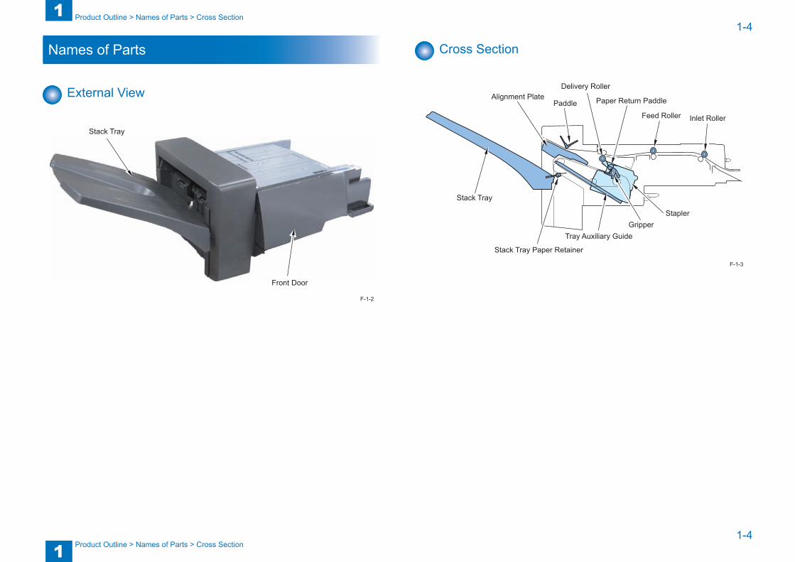
External View
Stack Tray
Front Door
F-1-2
Cross Section
Inlet Roller
PaddleFeed Roller
Alignment PlateDelivery Roller
Stapler
Stack Tray Paper Retainer
Tray Auxiliary Guide
Paper Return Paddle
Gripper
Stack Tray
F-1-3

2
2 Technology
Technology ■Basic Configuration ■Controls ■Basic Operation ■Feed Unit ■Processing Tray Unit ■Stack Tray Unit ■Controller Unit ■Detecting Jams ■Power Supply ■Work of Service
2
22-2
2-2
Technology > Basic Configuration > Overview of Electrical Circuitry
Technology > Basic Configuration > Overview of Electrical Circuitry
Basic Configuration
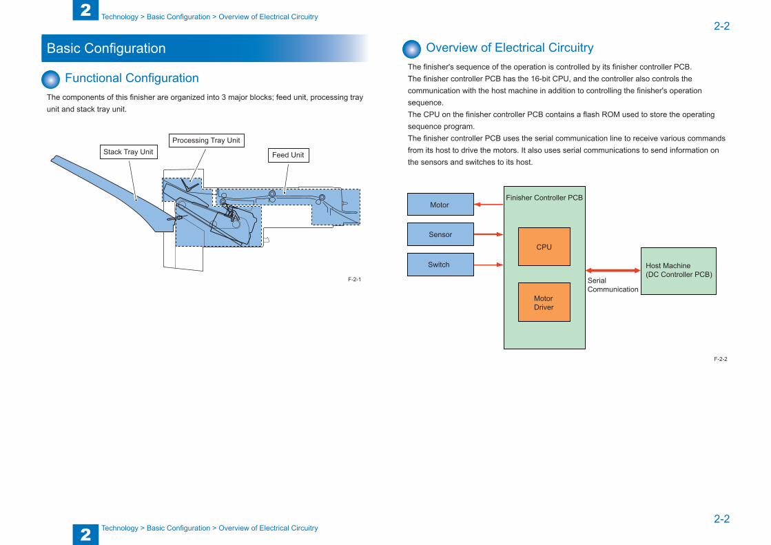
Functional ConfigurationThe components of this finisher are organized into 3 major blocks; feed unit, processing tray unit and stack tray unit.
Feed Unit
Processing Tray UnitStack Tray Unit
F-2-1
Overview of Electrical CircuitryThe finisher's sequence of the operation is controlled by its finisher controller PCB.The finisher controller PCB has the 16-bit CPU, and the controller also controls the communication with the host machine in addition to controlling the finisher's operation sequence.The CPU on the finisher controller PCB contains a flash ROM used to store the operating sequence program.The finisher controller PCB uses the serial communication line to receive various commands from its host to drive the motors. It also uses serial communications to send information on the sensors and switches to its host.
Motor
Sensor
Switch
Finisher Controller PCB
CPU
MotorDriver
SerialCommunication
Host Machine(DC Controller PCB)
F-2-2

2
22-3
2-3
Technology > Controls > Controls
Technology > Controls > Controls
Controls
ControlsItems Reference
Basic Operation Outline Refer to page 2-4Feed Unit Outline Refer to page 2-6
Feeding Paper to Processing Tray Unit
Refer to page 2-6
Processing Tray Unit Outline Refer to page 2-7Stacking Operation Refer to page 2-8Tray Auxiliary Guide Operation Refer to page 2-9Alignment / Shifting Operation Refer to page 2-10Staple Operation Refer to page 2-16Stack Delivery Operation Refer to page 2-16Stack Tray Paper Retainer Operation
Refer to page 2-17
Stack Tray Unit Stack Tray Shift Operation Refer to page 2-18Stack Tray Paper Height Detection Control
Refer to page 2-18
Stack Tray Paper Full Detection Control
Refer to page 2-19
Controller Unit Outline Refer to page 2-20Detecting Jams Outline Refer to page 2-21Power Supply Outline Refer to page 2-23
Protective Functions Refer to page 2-23Work of Service When replacing the parts Refer to page 2-24
Periodical Servicing Refer to page 2-24Upgrading Refer to page 2-24
T-2-1

2
22-4
2-4
Technology > Basic Operation > Outline
Technology > Basic Operation > Outline
Basic Operation
OutlineBasic operations of this finisher are described below.
(1) The paper delivered from the host machine is fed by the inlet roller, feed roller, and delivery roller.
Feed Roller
Delivery Roller
Inlet Roller
(2) The paper delivered by the delivery roller is stacked on the processing tray by the paddle. A paddle and a paper return paddle are used to align paper in the feed direction.
If two or more sheets with a length of 150 mm or more are stacked, the tray auxiliary guides slide out.
Paddle
Paper Return Paddle
Stack Tray Paper Retainer
F-2-3
F-2-4
(3) The alignment plates are used to align paper in the width direction. (In the illustration below, paper is aligned with reference to the central reference position.)
Rear Alignment Plate
Front Alignment Plate
(4) The operations described in (1) to (3) are repeated for each sheet to be stacked on the processing tray.
(5) The stacked sheets are stapled (only in the staple mode).
Stapler
F-2-5
F-2-6
2
22-5
2-5
Technology > Basic Operation > Outline
Technology > Basic Operation > Outline
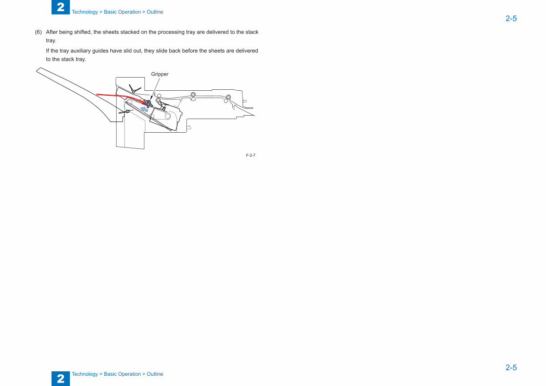
(6) After being shifted, the sheets stacked on the processing tray are delivered to the stack tray.
If the tray auxiliary guides have slid out, they slide back before the sheets are delivered to the stack tray.
Gripper
F-2-7

2
22-6
2-6
Technology > Feed Unit > Feeding Paper to Processing Tray Unit
Technology > Feed Unit > Feeding Paper to Processing Tray Unit
Feed Unit
OutlineThe feed unit feeds the paper delivered from the host machine and feeds it to the processing tray unit.Two sensors, an inlet sensor (S1) and a delivery sensor (S2), are provided along the paper feed path in the feed unit to detect the paper feed state and jam.
M1
S1S2
M2M3M4/5
M8 M7 M6 M9
M1 Feed Motor M7 Gripper MotorM2 Delivery Motor M8 Stack Tray Shift MotorM3 Paddle Motor M9 Staple MotorM4 Front Alignment Motor S1 Inlet SensorM5 Rear Alignment Motor S2 Delivery SensorM6 Tray Auxiliary Guide Motor
F-2-8
T-2-2
Feeding Paper to Processing Tray UnitThe paper delivered from the host machine is fed by the inlet roller, feed roller, and delivery roller.The paper delivered by the delivery roller is stacked on the processing tray by the paddle.
M1
M2
M3 Feed MotorPaddle Motor
Delivery Motor
Paddle
Delivery Sensor (S2)Inlet Sensor (S1)
Inlet RollerFeed Roller
Delivery Roller
F-2-9
2
22-7
2-7
Technology > Processing Tray Unit > Outline
Technology > Processing Tray Unit > Outline
Processing Tray Unit
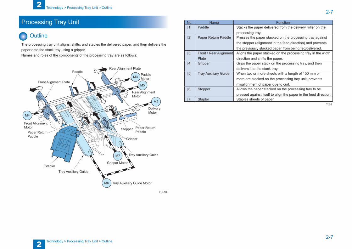
OutlineThe processing tray unit aligns, shifts, and staples the delivered paper, and then delivers the paper onto the stack tray using a gripper.Names and roles of the components of the processing tray are as follows:
M4
M6
M7
M3
M5
M2
PaddlePaddle Motor
Rear Alignment Plate
Rear Alignment Motor
DeliveryMotor
Paper Return Paddle
Tray Auxiliary Guide
Tray Auxiliary Guide
Tray Auxiliary Guide Motor
Gripper Motor
Gripper
Stopper
Stapler
Front Alignment Motor
Front Alignment Plate
Paper Return Paddle
F-2-10
No. Name Function[1] Paddle Stacks the paper delivered from the delivery roller on the
processing tray.[2] Paper Return Paddle Presses the paper stacked on the processing tray against
the stopper (alignment in the feed direction) and prevents the previously stacked paper from being fed/delivered.
[3] Front / Rear Alignment Plate
Aligns the paper stacked on the processing tray in the width direction and shifts the paper.
[4] Gripper Grips the paper stack on the processing tray, and then delivers it to the stack tray.
[5] Tray Auxiliary Guide When two or more sheets with a length of 150 mm or more are stacked on the processing tray unit, prevents misalignment of paper due to curl.
[6] Stopper Allows the paper stacked on the processing tray to be pressed against itself to align the paper in the feed direction.
[7] Stapler Staples sheets of paper.T-2-3

2
22-8
2-8
Technology > Processing Tray Unit > Stacking Operation
Technology > Processing Tray Unit > Stacking Operation
Stacking OperationThe paper delivered from the delivery roller is stacked on the processing tray and the paper is aligned in the feed direction.How paper is delivered from the delivery roller and stacked on the processing tray is described below.
(1) When two or more sheets with a length of 150 mm or more are stacked, the tray auxiliary guide motor (M6) operates after lapse of the specified time since detection of paper by the inlet sensor (S1), thus sliding out the tray auxiliary guides.
M6 Tray Auxiliary Guide Motor
Inlet Sensor (S1)Tray Auxiliary Guide
F-2-11
(2) After the specified time has lapsed since paper has passed through the delivery sensor (S2), the paddle motor (M3) operates to rotate the paddle once to stack the paper on the processing tray.
The stacked paper is pressed against the stopper by the paper return paddle which is driven by the delivery motor (M2), thus aligning the paper in the feed direction.
M2 Delivery Motor
M3 Paddle Motor
Delivery Sensor (S2)
Stopper
Paddle
Paper Return Paddle
NOTE:
When a postcard or a sheet shorter than 150 mm is stacked, the paddle does not rotate.
F-2-12

2
22-9
2-9
Technology > Processing Tray Unit > Tray Auxiliary Guide Operation
Technology > Processing Tray Unit > Tray Auxiliary Guide Operation
(3) The front and rear alignment motors (M4 and M5) operate to move the front and rear alignment plates, thus aligning the paper in the width direction. (In the illustration below, the paper is aligned with reference to the central reference position.)
Operations described in (2) and (3) are repeated for each sheet.
Rear Alignment Plate
Front Alignment Plate
F-2-13
Tray Auxiliary Guide OperationWhen two or more sheets with a length of 150 mm or more are stacked on the processing tray, the tray auxiliary guides slide out to prevent misalignment of paper due to curl.The tray auxiliary guides are driven by the tray auxiliary guide motor (M6). They slide out when the inlet sensor (S1) detects paper and they slide back when paper is delivered by the gripper.The home position of each tray auxiliary guide is detected by the tray auxiliary guide HP sensor (S6).
M6
Tray Auxiliary Guide Motor
Tray Auxiliary Guide HP Sensor (S6)
Tray Auxiliary Guide
Tray Auxiliary Guide
F-2-14
2
22-10
2-10
Technology > Processing Tray Unit > Alignment / Shifting Operation
Technology > Processing Tray Unit > Alignment / Shifting Operation
The tray auxiliary guide slide-out amount varies depending on the operation mode and paper length as follows:
Operation Mode Paper Length Amount of Slide OutNon-Sort / Sort 150 mm or more to less than
217 mm55 mm
217 mm or more to less than 300 mm
55 + ("Paper Length" - 216) mm
300 mm or more 120 mmStaple 150 mm or more to less than
217 mm50 mm
217 mm or more 55 + ("Paper Length" - 216) mmT-2-4
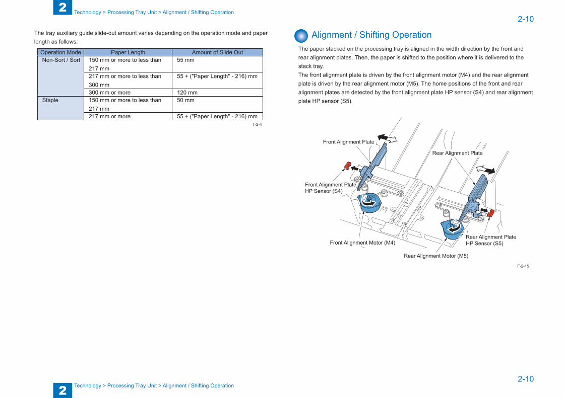
Alignment / Shifting OperationThe paper stacked on the processing tray is aligned in the width direction by the front and rear alignment plates. Then, the paper is shifted to the position where it is delivered to the stack tray.The front alignment plate is driven by the front alignment motor (M4) and the rear alignment plate is driven by the rear alignment motor (M5). The home positions of the front and rear alignment plates are detected by the front alignment plate HP sensor (S4) and rear alignment plate HP sensor (S5).
Rear Alignment Motor (M5)
Front Alignment Motor (M4)Rear Alignment Plate HP Sensor (S5)
Rear Alignment Plate
Front Alignment Plate HP Sensor (S4)
Front Alignment Plate
F-2-15
2
22-11
2-11
Technology > Processing Tray Unit > Alignment / Shifting Operation
Technology > Processing Tray Unit > Alignment / Shifting Operation
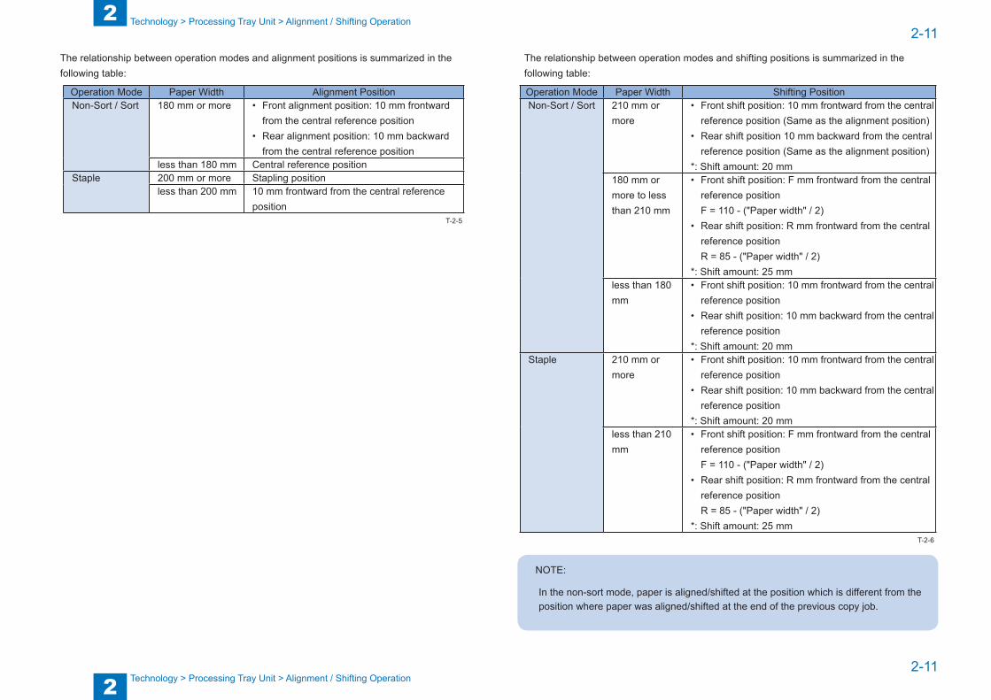
The relationship between operation modes and alignment positions is summarized in the following table:
Operation Mode Paper Width Alignment PositionNon-Sort / Sort 180 mm or more • Front alignment position: 10 mm frontward
from the central reference position• Rear alignment position: 10 mm backward
from the central reference positionless than 180 mm Central reference position
Staple 200 mm or more Stapling positionless than 200 mm 10 mm frontward from the central reference
positionT-2-5
The relationship between operation modes and shifting positions is summarized in the following table:
Operation Mode Paper Width Shifting PositionNon-Sort / Sort 210 mm or
more• Front shift position: 10 mm frontward from the central
reference position (Same as the alignment position) • Rear shift position 10 mm backward from the central
reference position (Same as the alignment position) *: Shift amount: 20 mm
180 mm or more to less than 210 mm
• Front shift position: F mm frontward from the central reference positionF = 110 - ("Paper width" / 2)
• Rear shift position: R mm frontward from the central reference positionR = 85 - ("Paper width" / 2)
*: Shift amount: 25 mmless than 180 mm
• Front shift position: 10 mm frontward from the central reference position
• Rear shift position: 10 mm backward from the central reference position
*: Shift amount: 20 mmStaple 210 mm or
more• Front shift position: 10 mm frontward from the central
reference position• Rear shift position: 10 mm backward from the central
reference position*: Shift amount: 20 mm
less than 210 mm
• Front shift position: F mm frontward from the central reference positionF = 110 - ("Paper width" / 2)
• Rear shift position: R mm frontward from the central reference positionR = 85 - ("Paper width" / 2)
*: Shift amount: 25 mm
NOTE:
In the non-sort mode, paper is aligned/shifted at the position which is different from the position where paper was aligned/shifted at the end of the previous copy job.
T-2-6
2
22-12
2-12
Technology > Processing Tray Unit > Alignment / Shifting Operation
Technology > Processing Tray Unit > Alignment / Shifting Operation
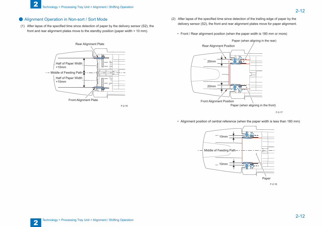
● Alignment Operation in Non-sort / Sort Mode(1) After lapse of the specified time since detection of paper by the delivery sensor (S2), the
front and rear alignment plates move to the standby position (paper width + 10 mm).
Half of Paper Width+10mm
Front Alignment Plate
Rear Alignment Plate
Middle of Feeding Path
Half of Paper Width+10mm
F-2-16
(2) After lapse of the specified time since detection of the trailing edge of paper by the delivery sensor (S2), the front and rear alignment plates move for paper alignment.
• Front / Rear alignment position (when the paper width is 180 mm or more)
20mm
Rear Alignment Position
Front Alignment Position
20mm
Paper (when aligning in the front)
Paper (when aligning in the rear)
• Alignment position of central reference (when the paper width is less than 180 mm)
10mm
10mm
Paper
Middle of Feeding Path
F-2-17
F-2-18
2
22-13
2-13
Technology > Processing Tray Unit > Alignment / Shifting Operation
Technology > Processing Tray Unit > Alignment / Shifting Operation
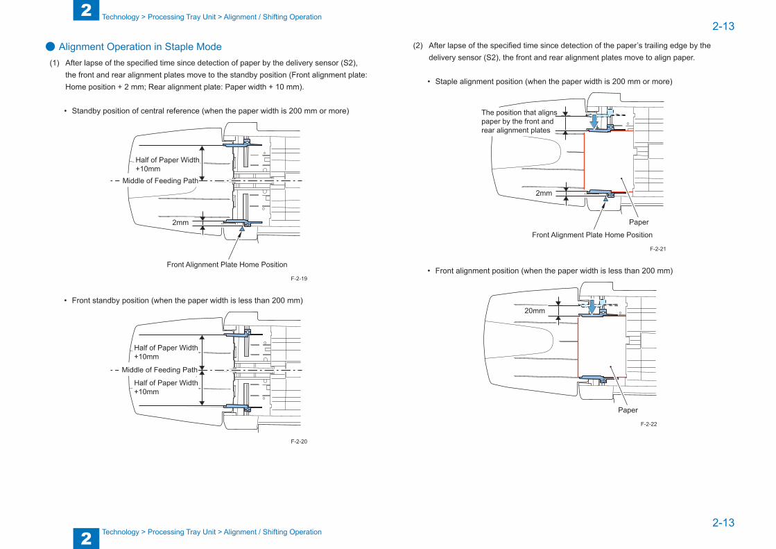
● Alignment Operation in Staple Mode(1) After lapse of the specified time since detection of paper by the delivery sensor (S2),
the front and rear alignment plates move to the standby position (Front alignment plate: Home position + 2 mm; Rear alignment plate: Paper width + 10 mm).
• Standby position of central reference (when the paper width is 200 mm or more)
2mm
Front Alignment Plate Home Position
Half of Paper Width+10mm
Middle of Feeding Path
• Front standby position (when the paper width is less than 200 mm)
Half of Paper Width+10mm
Middle of Feeding Path
Half of Paper Width+10mm
F-2-19
F-2-20
(2) After lapse of the specified time since detection of the paper’s trailing edge by the delivery sensor (S2), the front and rear alignment plates move to align paper.
• Staple alignment position (when the paper width is 200 mm or more)
2mm
Front Alignment Plate Home Position
The position that aligns paper by the front and rear alignment plates
Paper
• Front alignment position (when the paper width is less than 200 mm)
20mm
Paper
F-2-21
F-2-22
2
22-14
2-14
Technology > Processing Tray Unit > Alignment / Shifting Operation
Technology > Processing Tray Unit > Alignment / Shifting Operation
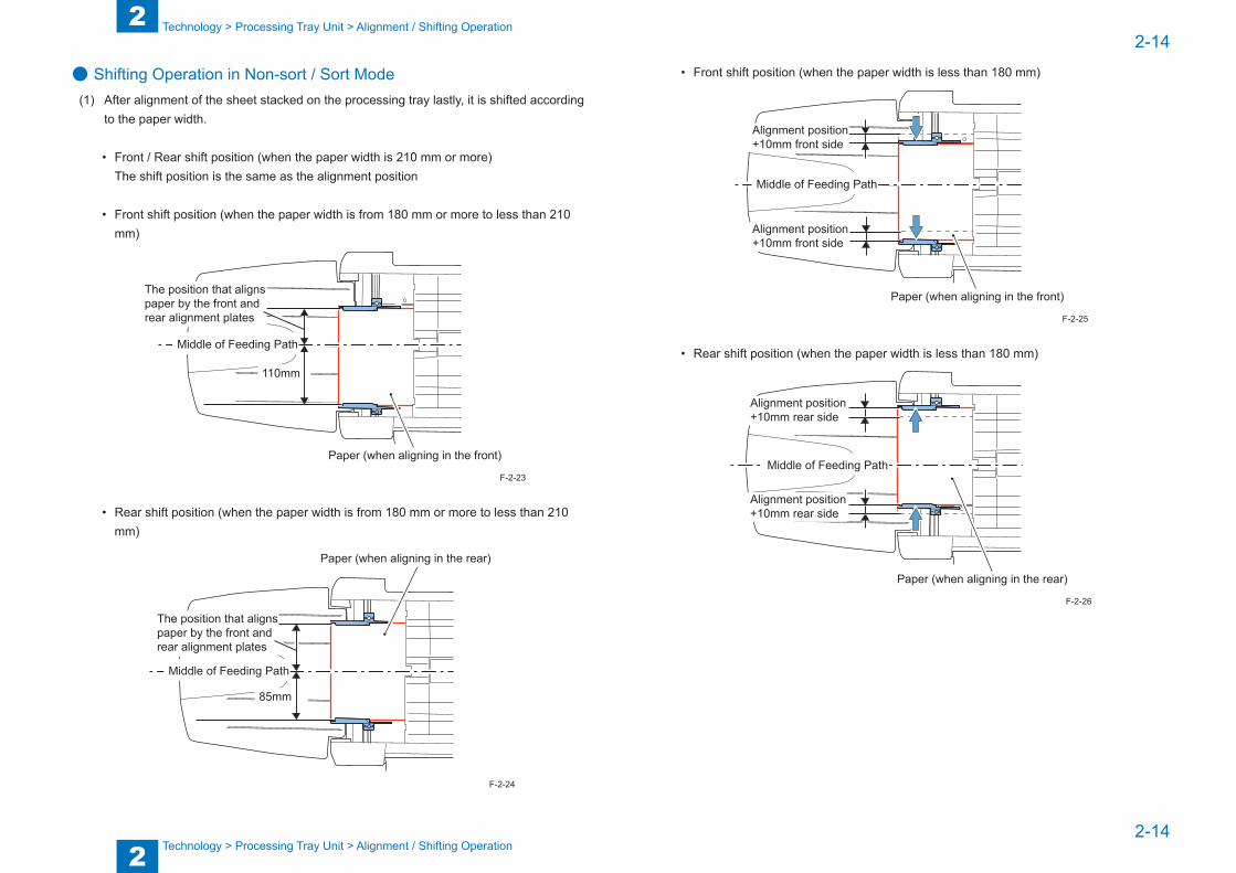
● Shifting Operation in Non-sort / Sort Mode(1) After alignment of the sheet stacked on the processing tray lastly, it is shifted according
to the paper width.
• Front / Rear shift position (when the paper width is 210 mm or more) The shift position is the same as the alignment position
• Front shift position (when the paper width is from 180 mm or more to less than 210 mm)
110mm
Paper (when aligning in the front)
The position that aligns paper by the front and rear alignment plates
Middle of Feeding Path
• Rear shift position (when the paper width is from 180 mm or more to less than 210 mm)
85mm
Paper (when aligning in the rear)
The position that aligns paper by the front and rear alignment plates
Middle of Feeding Path
F-2-23
F-2-24
• Front shift position (when the paper width is less than 180 mm)
Alignment position +10mm front side
Paper (when aligning in the front)
Middle of Feeding Path
Alignment position +10mm front side
• Rear shift position (when the paper width is less than 180 mm)
Paper (when aligning in the rear)
Alignment position +10mm rear side
Alignment position +10mm rear side
Middle of Feeding Path
F-2-25
F-2-26
2
22-15
2-15
Technology > Processing Tray Unit > Alignment / Shifting Operation
Technology > Processing Tray Unit > Alignment / Shifting Operation
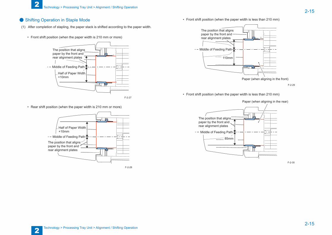
● Shifting Operation in Staple Mode(1) After completion of stapling, the paper stack is shifted according to the paper width.
• Front shift position (when the paper width is 210 mm or more)
Half of Paper Width+10mm
Middle of Feeding Path
The position that aligns paper by the front and rear alignment plates
• Rear shift position (when the paper width is 210 mm or more)
Middle of Feeding Path
Half of Paper Width+10mm
The position that aligns paper by the front and rear alignment plates
F-2-27
F-2-28
• Front shift position (when the paper width is less than 210 mm)
110mm
Paper (when aligning in the front)
Middle of Feeding Path
The position that aligns paper by the front and rear alignment plates
• Front shift position (when the paper width is less than 210 mm)
85mm
Paper (when aligning in the rear)
The position that aligns paper by the front and rear alignment plates
Middle of Feeding Path
F-2-29
F-2-30
2
22-16
2-16
Technology > Processing Tray Unit > Stack Delivery Operation
Technology > Processing Tray Unit > Stack Delivery Operation
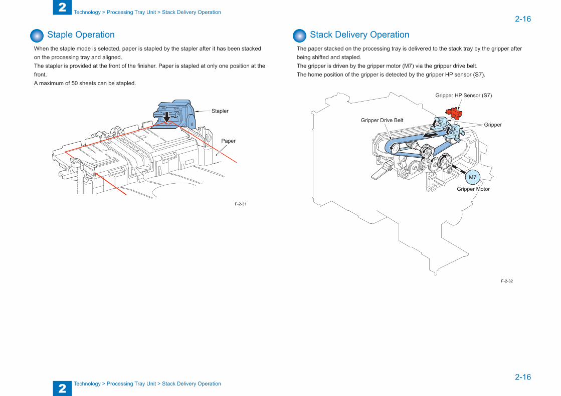
Staple OperationWhen the staple mode is selected, paper is stapled by the stapler after it has been stacked on the processing tray and aligned.The stapler is provided at the front of the finisher. Paper is stapled at only one position at the front. A maximum of 50 sheets can be stapled.
Stapler
Paper
F-2-31
Stack Delivery OperationThe paper stacked on the processing tray is delivered to the stack tray by the gripper after being shifted and stapled.The gripper is driven by the gripper motor (M7) via the gripper drive belt.The home position of the gripper is detected by the gripper HP sensor (S7).
M7
Gripper Motor
Gripper Drive BeltGripper
Gripper HP Sensor (S7)
F-2-32
2
22-17
2-17
Technology > Processing Tray Unit > Stack Tray Paper Retainer Operation
Technology > Processing Tray Unit > Stack Tray Paper Retainer Operation
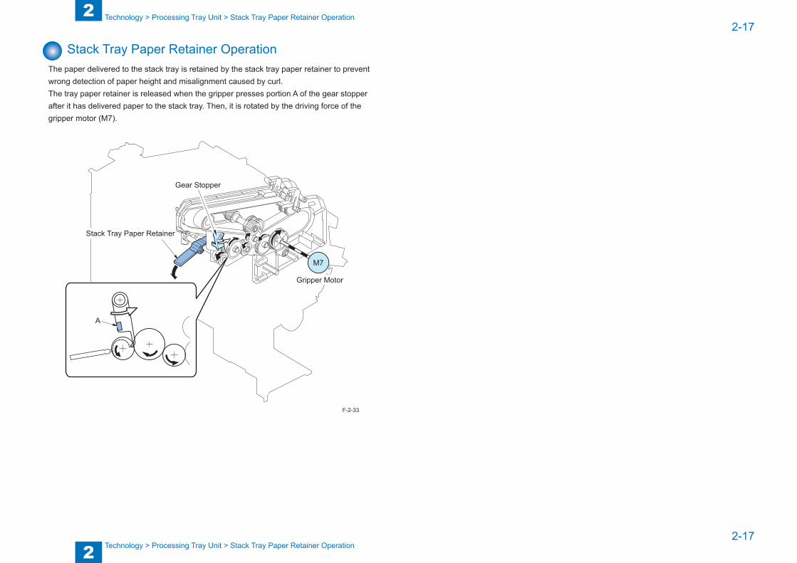
Stack Tray Paper Retainer OperationThe paper delivered to the stack tray is retained by the stack tray paper retainer to prevent wrong detection of paper height and misalignment caused by curl.The tray paper retainer is released when the gripper presses portion A of the gear stopper after it has delivered paper to the stack tray. Then, it is rotated by the driving force of the gripper motor (M7).
M7
Stack Tray Paper Retainer
Gripper Motor
A
Gear Stopper
F-2-33
2
22-18
2-18
Technology > Stack Tray Unit > Stack Tray Paper Height Detection Control
Technology > Stack Tray Unit > Stack Tray Paper Height Detection Control
Stack Tray Unit
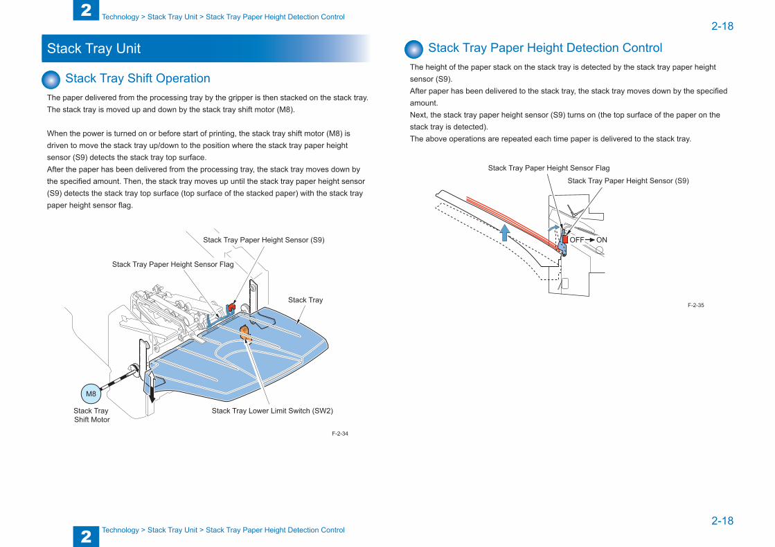
Stack Tray Shift OperationThe paper delivered from the processing tray by the gripper is then stacked on the stack tray.The stack tray is moved up and down by the stack tray shift motor (M8).
When the power is turned on or before start of printing, the stack tray shift motor (M8) is driven to move the stack tray up/down to the position where the stack tray paper height sensor (S9) detects the stack tray top surface.After the paper has been delivered from the processing tray, the stack tray moves down by the specified amount. Then, the stack tray moves up until the stack tray paper height sensor (S9) detects the stack tray top surface (top surface of the stacked paper) with the stack tray paper height sensor flag.
M8
Stack Tray Paper Height Sensor Flag
Stack Tray
Stack Tray Lower Limit Switch (SW2)Stack Tray Shift Motor
Stack Tray Paper Height Sensor (S9)
F-2-34
Stack Tray Paper Height Detection ControlThe height of the paper stack on the stack tray is detected by the stack tray paper height sensor (S9).After paper has been delivered to the stack tray, the stack tray moves down by the specified amount.Next, the stack tray paper height sensor (S9) turns on (the top surface of the paper on the stack tray is detected).The above operations are repeated each time paper is delivered to the stack tray.
Stack Tray Paper Height Sensor Flag
Stack Tray Paper Height Sensor (S9)
OFF ON
F-2-35

2
22-19
2-19
Technology > Stack Tray Unit > Stack Tray Paper Full Detection Control
Technology > Stack Tray Unit > Stack Tray Paper Full Detection Control
Stack Tray Paper Full Detection ControlThe paper full state of the stack tray is detected by the stack tray paper height sensor (S9) and stack tray lower limit switch (SW2).
Stack Tray Lower Limit Switch (SW2)
ON
Stack Tray Paper Height Sensor (S9)
ON
The paper full state of the stack tray is detected in the following cases: • When the power is turned on or during initialization before start of printing
When the ON states of both the stack tray paper height sensor (S9) and stack tray lower limit switch (SW2) are detected
• When paper is deliveredWhen the ON state of the stack tray lower limit switch is detected two successive times because the height of the paper delivered to the stack tray has become lower than the specified level
NOTE:
After the stack tray full state has been detected, a maximum of 50 sheets can be stacked on the stack tray.
F-2-36
2
22-20
2-20
Technology > Controller Unit > Outline
Technology > Controller Unit > Outline
Controller Unit
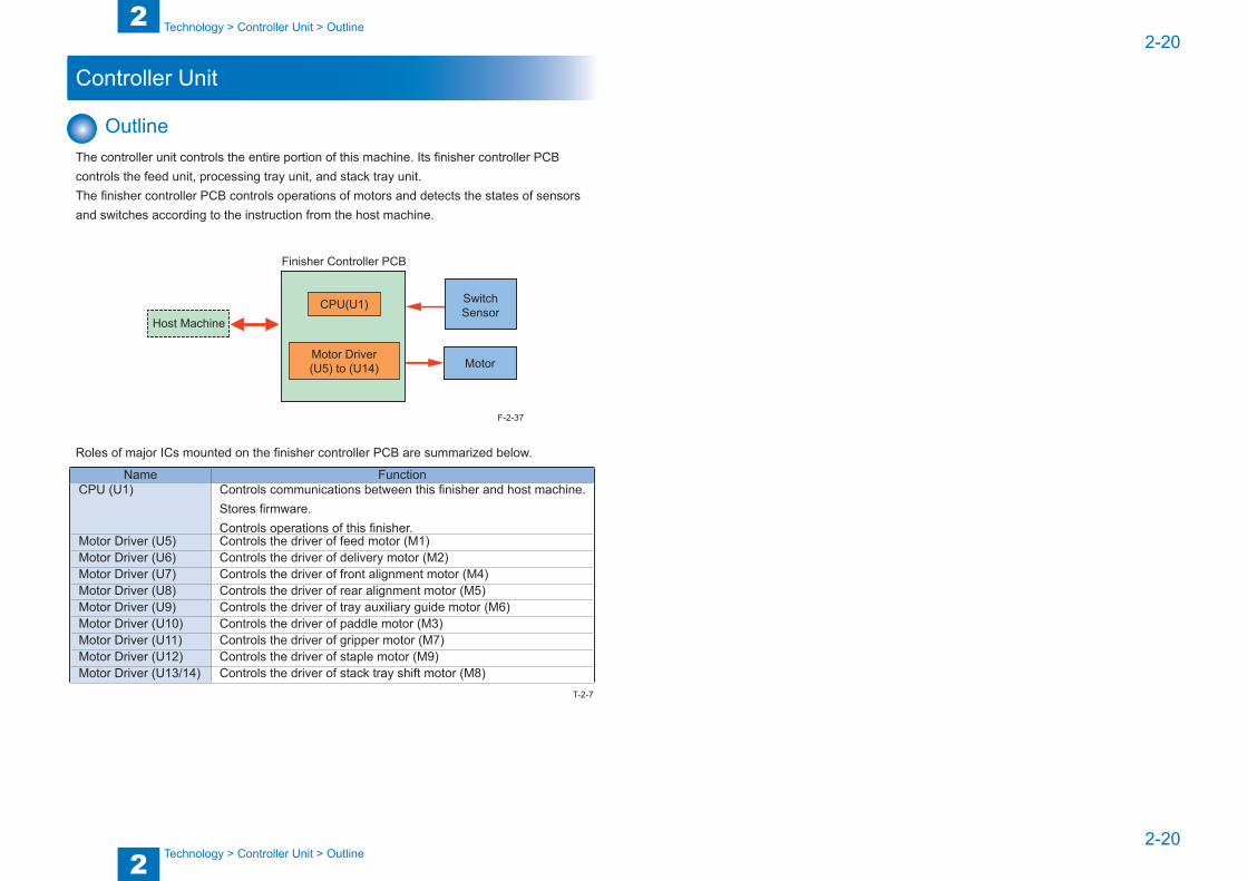
OutlineThe controller unit controls the entire portion of this machine. Its finisher controller PCB controls the feed unit, processing tray unit, and stack tray unit.The finisher controller PCB controls operations of motors and detects the states of sensors and switches according to the instruction from the host machine.
Finisher Controller PCB
Motor
SwitchSensor
CPU(U1)
Motor Driver(U5) to (U14)
Host Machine
Roles of major ICs mounted on the finisher controller PCB are summarized below.
Name FunctionCPU (U1) Controls communications between this finisher and host machine.
Stores firmware.Controls operations of this finisher.
Motor Driver (U5) Controls the driver of feed motor (M1)Motor Driver (U6) Controls the driver of delivery motor (M2)Motor Driver (U7) Controls the driver of front alignment motor (M4)Motor Driver (U8) Controls the driver of rear alignment motor (M5)Motor Driver (U9) Controls the driver of tray auxiliary guide motor (M6)Motor Driver (U10) Controls the driver of paddle motor (M3)Motor Driver (U11) Controls the driver of gripper motor (M7)Motor Driver (U12) Controls the driver of staple motor (M9)Motor Driver (U13/14) Controls the driver of stack tray shift motor (M8)
F-2-37
T-2-7
2
22-21
2-21
Technology > Detecting Jams > Outline
Technology > Detecting Jams > Outline
Detecting Jams
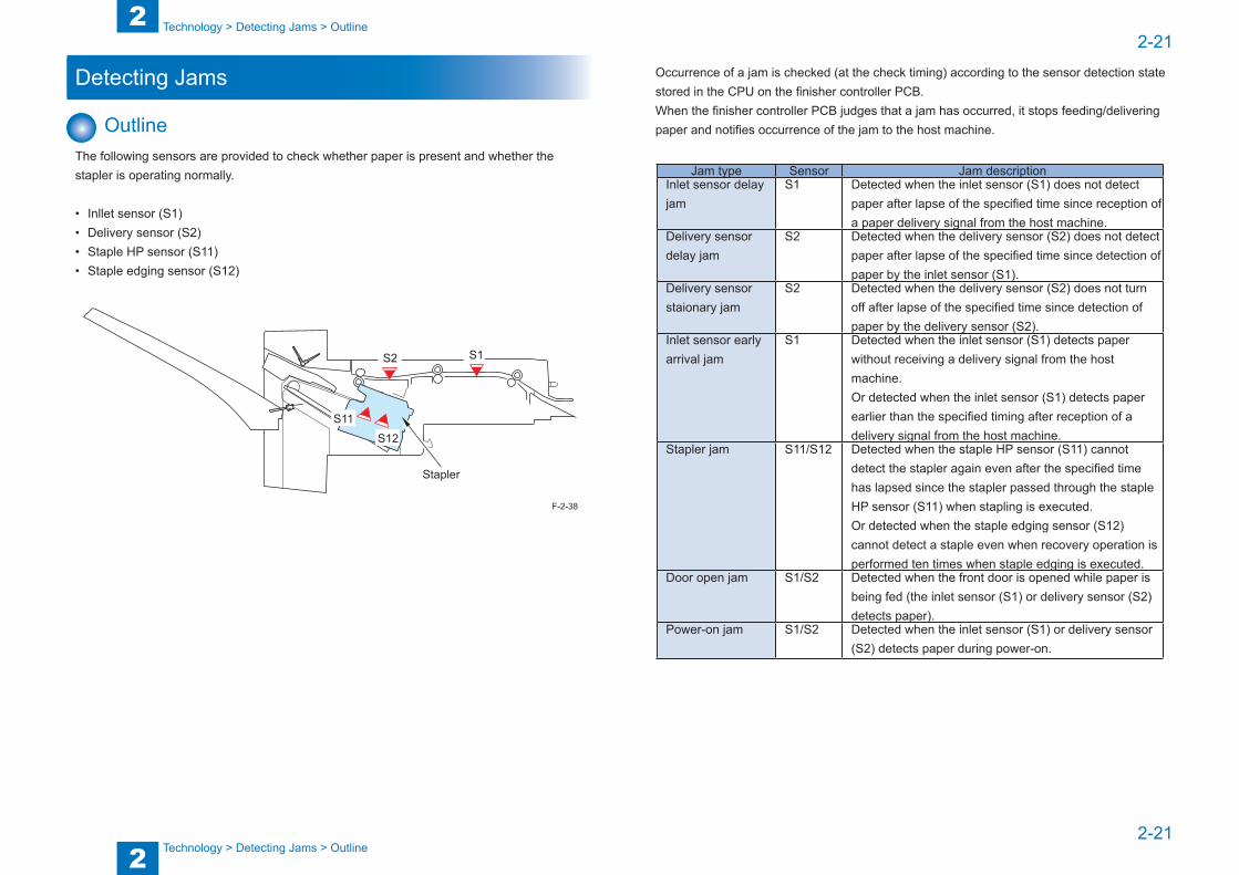
OutlineThe following sensors are provided to check whether paper is present and whether the stapler is operating normally.
• Inllet sensor (S1)• Delivery sensor (S2)• Staple HP sensor (S11)• Staple edging sensor (S12)
S1S2
S11
S12
Stapler
F-2-38
Occurrence of a jam is checked (at the check timing) according to the sensor detection state stored in the CPU on the finisher controller PCB.When the finisher controller PCB judges that a jam has occurred, it stops feeding/delivering paper and notifies occurrence of the jam to the host machine.
Jam type Sensor Jam descriptionInlet sensor delay jam
S1 Detected when the inlet sensor (S1) does not detect paper after lapse of the specified time since reception of a paper delivery signal from the host machine.
Delivery sensor delay jam
S2 Detected when the delivery sensor (S2) does not detect paper after lapse of the specified time since detection of paper by the inlet sensor (S1).
Delivery sensor staionary jam
S2 Detected when the delivery sensor (S2) does not turn off after lapse of the specified time since detection of paper by the delivery sensor (S2).
Inlet sensor early arrival jam
S1 Detected when the inlet sensor (S1) detects paper without receiving a delivery signal from the host machine.Or detected when the inlet sensor (S1) detects paper earlier than the specified timing after reception of a delivery signal from the host machine.
Stapler jam S11/S12 Detected when the staple HP sensor (S11) cannot detect the stapler again even after the specified time has lapsed since the stapler passed through the staple HP sensor (S11) when stapling is executed.Or detected when the staple edging sensor (S12) cannot detect a staple even when recovery operation is performed ten times when staple edging is executed.
Door open jam S1/S2 Detected when the front door is opened while paper is being fed (the inlet sensor (S1) or delivery sensor (S2) detects paper).
Power-on jam S1/S2 Detected when the inlet sensor (S1) or delivery sensor (S2) detects paper during power-on.

2
22-22
2-22
Technology > Detecting Jams > Outline
Technology > Detecting Jams > Outline
Jam type Sensor Jam descriptionError avoidance jam
- When the controller detected the following errors during feeding operation.• Error in the paddle motor (E577)• Error in the front alignment motor (E530)• Error in the rear alignment motor (E537)• Error in the tray auxiliary guide motor (E583)• Error in the gripper motor (E575)• Error in the stack tray shift motor (E540)• Error in the staple motor (E531)
T-2-8
2
22-23
2-23
Technology > Power Supply > Protective Functions
Technology > Power Supply > Protective Functions
Power Supply
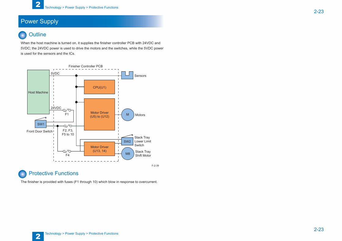
OutlineWhen the host machine is turned on, it supplies the finisher controller PCB with 24VDC and 5VDC; the 24VDC power is used to drive the motors and the switches, while the 5VDC power is used for the sensors and the ICs.
SW1
SW2
M
M8 Stack Tray Shift Motor
Stack Tray Lower Limit Switch
Motors
Sensors
Motor Driver(U13, 14)
Finisher Controller PCB
Motor Driver(U5) to (U12)
CPU(U1)Host Machine
Front Door Switch
F1
F2, F3,F5 to 10
F4
5VDC
24VDC
Protective FunctionsThe finisher is provided with fuses (F1 through 10) which blow in response to overcurrent.
F-2-39
2
22-24
2-24
Technology > Work of Service > Upgrading
Technology > Work of Service > Upgrading
Work of Service
When replacing the partsWhen you have replaced the finisher controller PCB with the service parts, check that the firmware is the latest version. If it is not the latest version, upgrade it.
Periodical ServicingThis finisher has no periodic service items.
UpgradingWhen upgrading the firmware of the finisher controller PCB, upgrade from the host machine.(Refer to the service manual for the host machine as to the detail.)
3
3 Periodic Servicing
Periodic Servicing
■List of Work for Scheduled Servicing

3
33-2
3-2
Periodic Servicing > List of Work for Scheduled Servicing
Periodic Servicing > List of Work for Scheduled Servicing
List of Work for Scheduled ServicingThere is no item that requires the scheduled service in this finisher..

4
4 Parts Replacement and Cleaning Procedure
Parts Replacement and Cleaning Procedure
■Finisher ■List of Parts ■External / Internal Covers ■Main Units ■Motors ■Switches ■PCBs
4
44-2
4-2
Parts Replacement and Cleaning Procedure > Finisher > Detaching the Finisher from the Host Machine
Parts Replacement and Cleaning Procedure > Finisher > Detaching the Finisher from the Host Machine
Finisher
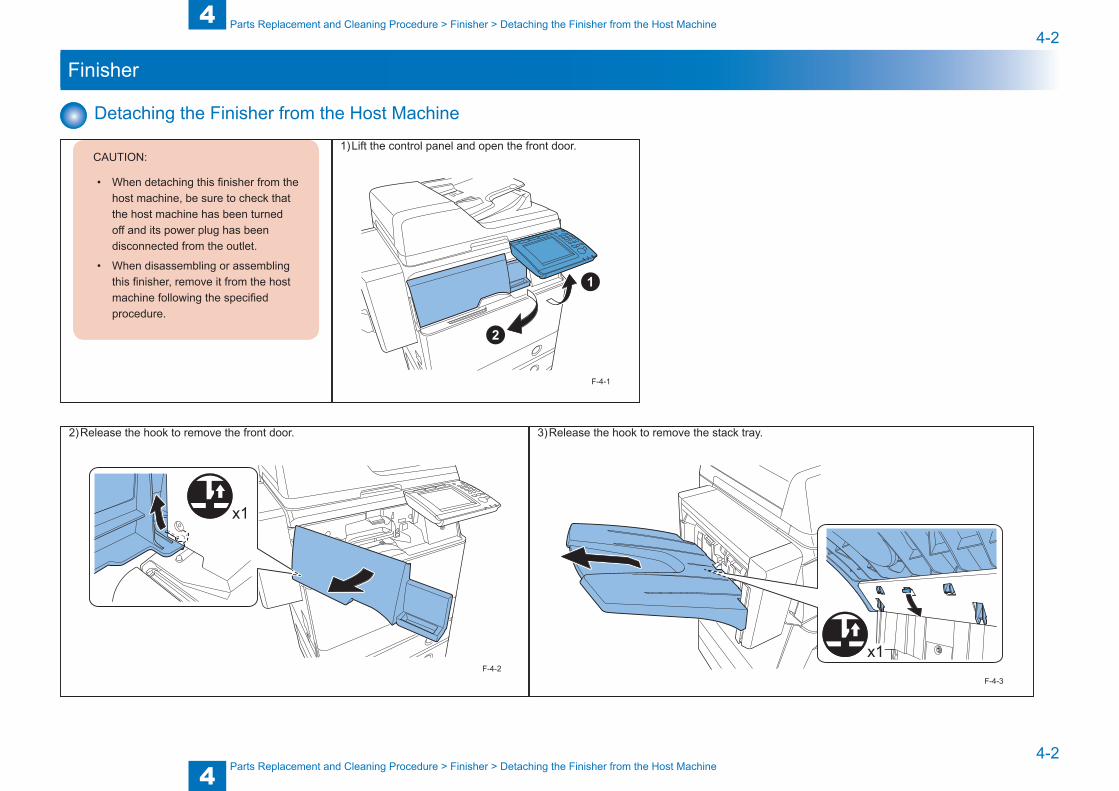
Detaching the Finisher from the Host Machine
CAUTION:
• When detaching this finisher from the host machine, be sure to check that the host machine has been turned off and its power plug has been disconnected from the outlet.
• When disassembling or assembling this finisher, remove it from the host machine following the specified procedure.
1) Lift the control panel and open the front door.
F-4-1
2) Release the hook to remove the front door.
x1
F-4-2
3) Release the hook to remove the stack tray.
x1
F-4-3

4
44-3
4-3
Parts Replacement and Cleaning Procedure > Finisher > Detaching the Finisher from the Host Machine
Parts Replacement and Cleaning Procedure > Finisher > Detaching the Finisher from the Host Machine
4) Insert a screwdriver or the like in the hole [A] to release the hook, and then slide the finisher leftward until it stops.
A
F-4-4
NOTE:
After releasing the hook by sliding the finisher 2-3 cm, you can remove the screwdriver or the like.
NOTE:
The hook may not be released completely with the finisher at the leftmost position. In this case, slide the finisher 1-2 cm back and raise the lever to release the hook.
5) While releasing the hook by raising the lever, remove the finisher from the host machine.
F-4-5
4
44-4
4-4
Parts Replacement and Cleaning Procedure > List of Parts > External / Internal Covers > Rear
Parts Replacement and Cleaning Procedure > List of Parts > External / Internal Covers > Rear
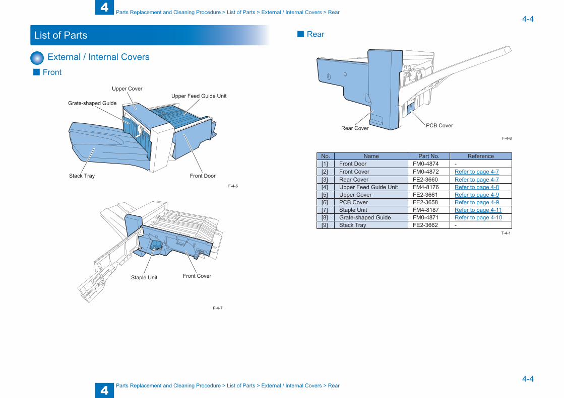
List of Parts
External / Internal Covers ■ Front
Front Door
Upper Feed Guide UnitUpper Cover
Grate-shaped Guide
Stack Tray
Front CoverStaple Unit
F-4-6
F-4-7
■ Rear
PCB CoverRear Cover
No. Name Part No. Reference[1] Front Door FM0-4874 -[2] Front Cover FM0-4872 Refer to page 4-7[3] Rear Cover FE2-3660 Refer to page 4-7[4] Upper Feed Guide Unit FM4-8176 Refer to page 4-8[5] Upper Cover FE2-3661 Refer to page 4-9[6] PCB Cover FE2-3658 Refer to page 4-9[7] Staple Unit FM4-8187 Refer to page 4-11[8] Grate-shaped Guide FM0-4871 Refer to page 4-10[9] Stack Tray FE2-3662 -
F-4-8
T-4-1

4
44-5
4-5
Parts Replacement and Cleaning Procedure > List of Parts > List of Motors
Parts Replacement and Cleaning Procedure > List of Parts > List of Motors
Main Units
Upper Processing Tray Unit (Rear)
Upper Processing Tray Unit (Front)Lower Processing Tray Unit
No. Name Part No. Reference[1] Upper Processing Tray Unit (Front) FM0-4865 Refer to page 4-12[2] Upper Processing Tray Unit (Rear) FM0-4866 Refer to page 4-12[3] Lower Processing Tray Unit - Refer to page 4-15
F-4-9
T-4-2
List of Motors
M9
M1
M3
M2M5
M8 M4M7
M6
No. Name Part No. ReferenceM1 Feed Motor FM4-8171 Refer to page 4-16M2 Delivery Motor FK3-1668 Refer to page 4-17M3 Paddle Motor FM4-8183 Refer to page 4-18M4 Front Alignment Motor FM4-8181 Refer to page 4-18M5 Rear Alignment Motor FM4-8181 Refer to page 4-19M6 Tray Auxiliary Guide Motor FM4-8183 Refer to page 4-19M7 Gripper Motor - -M8 Stack Tray Shift Motor FM4-8201 Refer to page 4-20M9 Staple Motor - -
F-4-10
T-4-3

4
44-6
4-6
Parts Replacement and Cleaning Procedure > List of Parts > List of PCBs
Parts Replacement and Cleaning Procedure > List of Parts > List of PCBs
List of Sensors and Switches
S5 S2
S10S3
S4
S8
S6
S11/S12/S13
S9
S1
S7SW1
SW2
No. Name Part No. ReferenceS1 Inlet Sensor WG8-5776 -S2 Delivery Sensor WG8-5776 -S3 Paddle HP Sensor WG8-5776 -S4 Front Alignment Plate HP Sensor WG8-5776 -S5 Rear Alignment Plate HP Sensor WG8-5776 -S6 Tray Auxiliary Guide HP Sensor WG8-5776 -S7 Gripper HP Sensor WG8-5776 -S8 Gripper Encoder Sensor WG8-5776 -S9 Stack Tray Paper Height Sensor WG8-5776 -S10 Staple Paper Detection Sensor FK2-1772 -S11 Staple HP Sensor - -S12 Staple Edging Sensor - -S13 Staple Sensor - -SW1 Front Door Switch FK3-1665 Refer to page 4-22SW2 Stack Tray Lower Limit Switch FK3-1664 Refer to page 4-23
F-4-11
T-4-4
List of PCBs
PCB1
No. Name Part No. ReferencePCB1 Finisher Controller PCB FM4-8199 Refer to page 4-24
F-4-12
T-4-5
4
44-7
4-7
Parts Replacement and Cleaning Procedure > External / Internal Covers > Removing the Rear Cover
Parts Replacement and Cleaning Procedure > External / Internal Covers > Removing the Rear Cover
External / Internal Covers
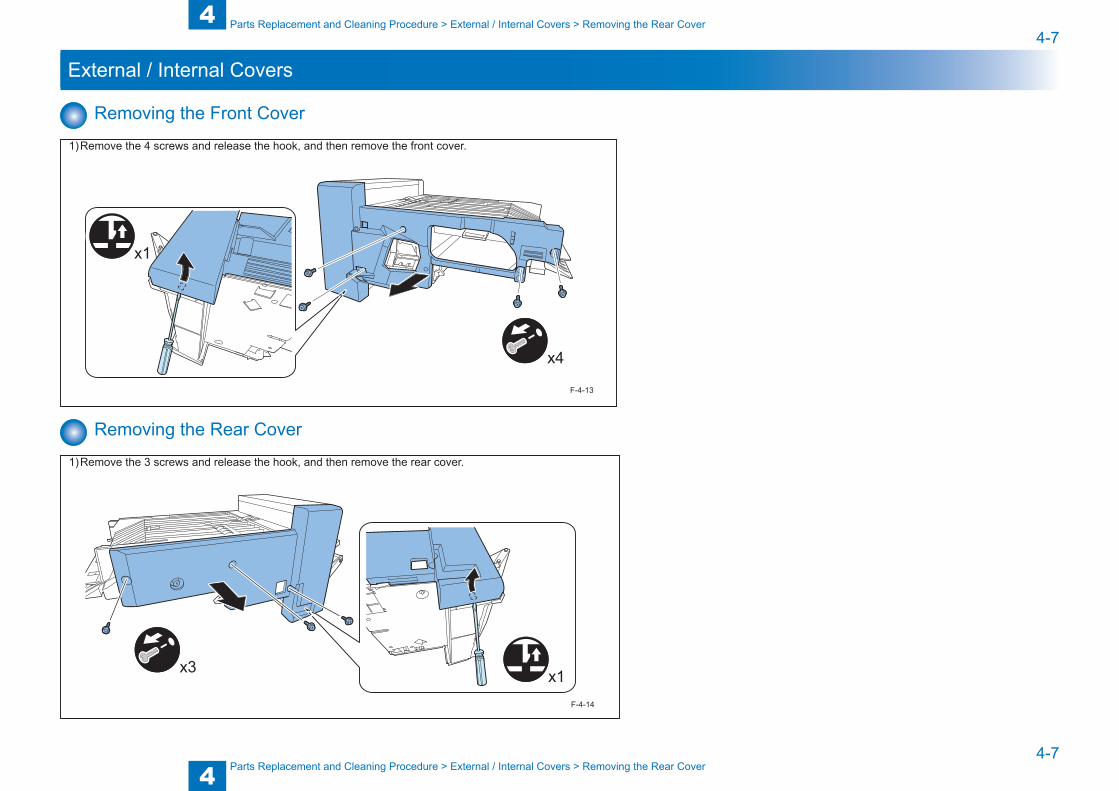
Removing the Front Cover
1) Remove the 4 screws and release the hook, and then remove the front cover.
x1
x4
F-4-13
Removing the Rear Cover
1) Remove the 3 screws and release the hook, and then remove the rear cover.
x3 x1F-4-14
4
44-8
4-8
Parts Replacement and Cleaning Procedure > External / Internal Covers > Removing the Upper Feed Guide Unit
Parts Replacement and Cleaning Procedure > External / Internal Covers > Removing the Upper Feed Guide Unit
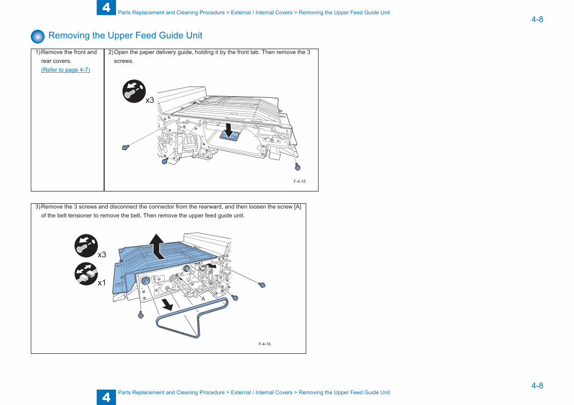
Removing the Upper Feed Guide Unit
1) Remove the front and rear covers.
(Refer to page 4-7)
2) Open the paper delivery guide, holding it by the front tab. Then remove the 3 screws.
x3
F-4-15
3) Remove the 3 screws and disconnect the connector from the rearward, and then loosen the screw [A] of the belt tensioner to remove the belt. Then remove the upper feed guide unit.
x3
x1
A
F-4-16
4
44-9
4-9
Parts Replacement and Cleaning Procedure > External / Internal Covers > Removing the PCB Cover
Parts Replacement and Cleaning Procedure > External / Internal Covers > Removing the PCB Cover
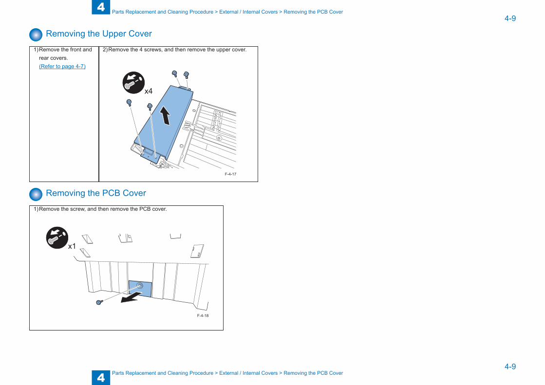
Removing the Upper Cover
1) Remove the front and rear covers.
(Refer to page 4-7)
2) Remove the 4 screws, and then remove the upper cover.
x4
F-4-17
Removing the PCB Cover
1) Remove the screw, and then remove the PCB cover.
x1
F-4-18

4
44-10
4-10
Parts Replacement and Cleaning Procedure > Main Units > Removing the Grate-shaped Guide
Parts Replacement and Cleaning Procedure > Main Units > Removing the Grate-shaped Guide
Main Units
Removing the Grate-shaped Guide
1) Remove the front and rear covers. (Refer to page 4-7)
2) Loosen the 2 screws [A], and then remove the stack tray support plate by loosening the 2 screws.
x2
A
A
F-4-19

4
44-11
4-11
Parts Replacement and Cleaning Procedure > Main Units > Removing the Staple Unit
Parts Replacement and Cleaning Procedure > Main Units > Removing the Staple Unit
3) Remove the 4 screws and disconnect the connector, and then remove the grate-shaped guide.
x2 x2
x1
F-4-20
Removing the Staple Unit
1) Removing the front cover (Refer to page 4-7)
2) Remove the 2 screws and disconnect the 2 connectors, and then remove the staple unit.
x2
x2
F-4-21
4
44-12
4-12
Parts Replacement and Cleaning Procedure > Main Units > Removing the Upper Processing Tray Unit (Front / Rear)
Parts Replacement and Cleaning Procedure > Main Units > Removing the Upper Processing Tray Unit (Front / Rear)
Removing the Upper Processing Tray Unit (Front / Rear)
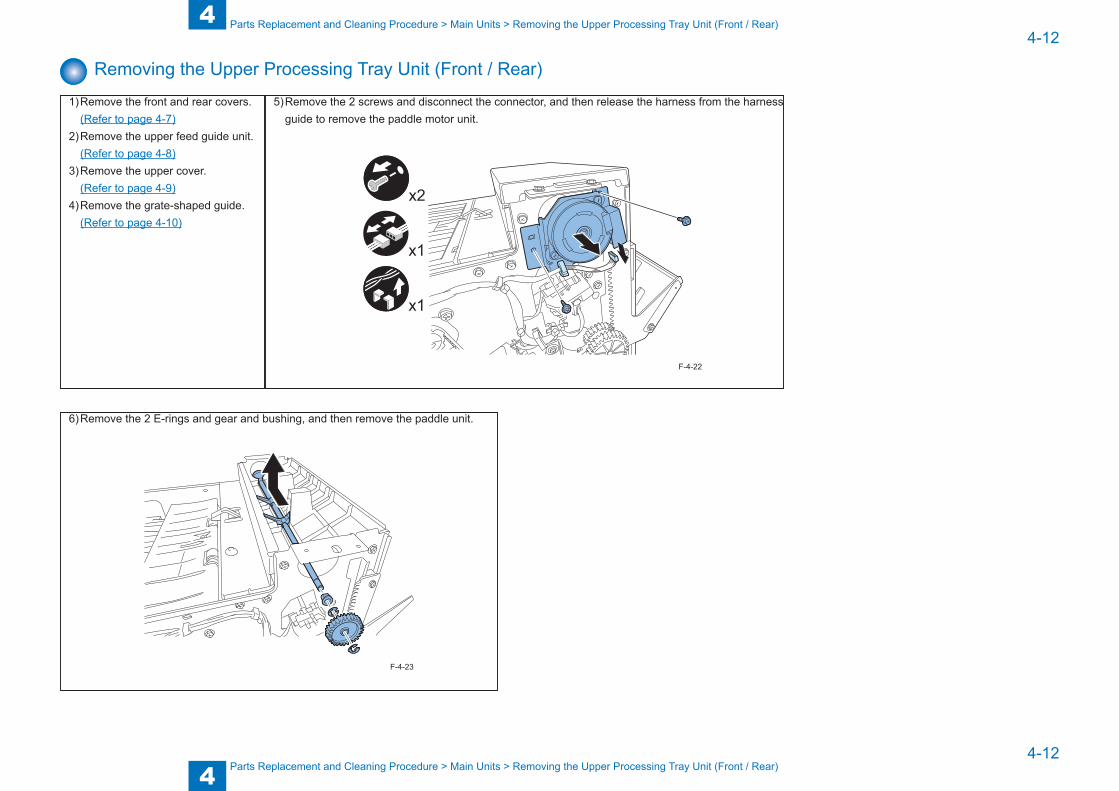
1) Remove the front and rear covers. (Refer to page 4-7)2) Remove the upper feed guide unit. (Refer to page 4-8)3) Remove the upper cover. (Refer to page 4-9)4) Remove the grate-shaped guide. (Refer to page 4-10)
5) Remove the 2 screws and disconnect the connector, and then release the harness from the harness guide to remove the paddle motor unit.
x1
x2
x1
F-4-22
6) Remove the 2 E-rings and gear and bushing, and then remove the paddle unit.
F-4-23

4
44-13
4-13
Parts Replacement and Cleaning Procedure > Main Units > Removing the Upper Processing Tray Unit (Front / Rear)
Parts Replacement and Cleaning Procedure > Main Units > Removing the Upper Processing Tray Unit (Front / Rear)
7) Remove the 4 screws, and then remove the support plate.
x4
F-4-24
8) Remove the 4 screws, and then remove the delivery guide.
x4
F-4-25
9) Remove the 5 screws and disconnect the connector, and remove the belt by loosening the 2 screws [A] securing the delivery motor unit, and then remove the delivery unit.
x5
x1
A A
F-4-26
CAUTION:
When tightening the screws securing the delivery motor unit, attach the belt and then tighten them at the position where tension is applied to the belt due to the motor's own weight.
F-4-27
4
44-14
4-14
Parts Replacement and Cleaning Procedure > Main Units > Removing the Upper Processing Tray Unit (Front / Rear)
Parts Replacement and Cleaning Procedure > Main Units > Removing the Upper Processing Tray Unit (Front / Rear)
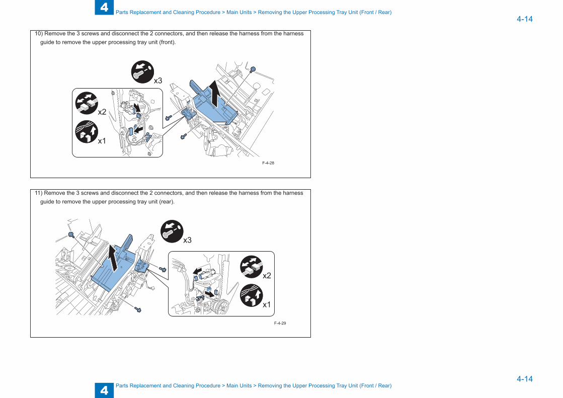
10) Remove the 3 screws and disconnect the 2 connectors, and then release the harness from the harness guide to remove the upper processing tray unit (front).
x3
x2
x1
F-4-28
11) Remove the 3 screws and disconnect the 2 connectors, and then release the harness from the harness guide to remove the upper processing tray unit (rear).
x3
x2
x1
F-4-29

4
44-15
4-15
Parts Replacement and Cleaning Procedure > Main Units > Removing the Lower Processing Tray Unit
Parts Replacement and Cleaning Procedure > Main Units > Removing the Lower Processing Tray Unit
Removing the Lower Processing Tray Unit
1) Remove the upper processing tray unit (front/rear).
(Refer to page 4-12)2) Remove the finisher controller PCB. (Refer to page 4-24)
3) Remove the 2 screws and disconnect the 4 connectors, and then release the harness from the harness guide to remove the lower processing tray unit.
x2
x1
x2
x3
F-4-30

4
44-16
4-16
Parts Replacement and Cleaning Procedure > Motors > Removing the Feed Motor (M1)
Parts Replacement and Cleaning Procedure > Motors > Removing the Feed Motor (M1)
Motors
Removing the Feed Motor (M1)
1) Remove the rear cover. (Refer to page 4-7)
2) Remove the 2 screws and disconnect the connector, and remove the belt by loosening the screw [A] of the belt tensioner, and then remove the feed motor along with its support plate.
x2
x1
A
F-4-31
3) Remove the 2 screws, and then remove the feed motor.
x2
F-4-32
CAUTION:
When attaching the feed motor to the support plate, tighten the 2 screws in such a manner that the clearance between the motor and support place is about 1.0 mm to 1.5 mm.
Approx. 1.0mm to 1.5mm
F-4-33
4
44-17
4-17
Parts Replacement and Cleaning Procedure > Motors > Removing the Delivery Motor (M2)
Parts Replacement and Cleaning Procedure > Motors > Removing the Delivery Motor (M2)
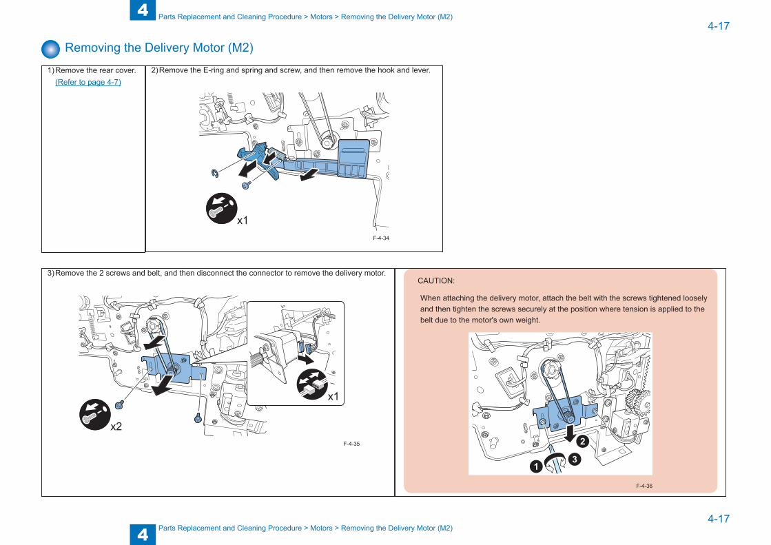
Removing the Delivery Motor (M2)
1) Remove the rear cover. (Refer to page 4-7)
2) Remove the E-ring and spring and screw, and then remove the hook and lever.
x1F-4-34
3) Remove the 2 screws and belt, and then disconnect the connector to remove the delivery motor.
x2
x1
F-4-35
CAUTION:
When attaching the delivery motor, attach the belt with the screws tightened loosely and then tighten the screws securely at the position where tension is applied to the belt due to the motor's own weight.
F-4-36
4
44-18
4-18
Parts Replacement and Cleaning Procedure > Motors > Removing the Front Alignment Motor (M4)
Parts Replacement and Cleaning Procedure > Motors > Removing the Front Alignment Motor (M4)
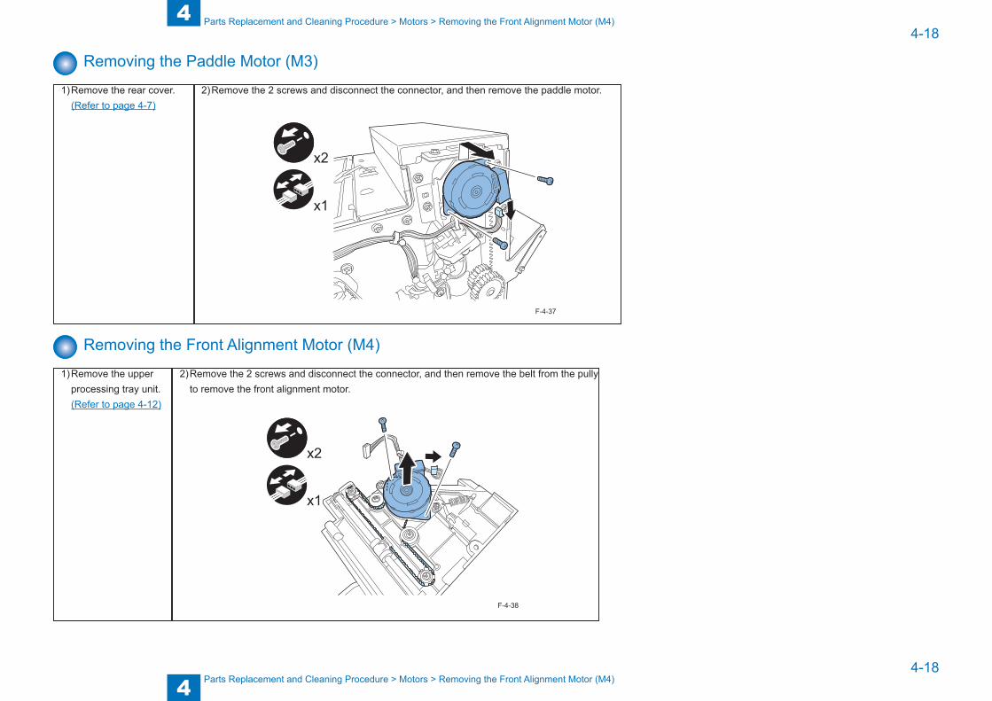
Removing the Paddle Motor (M3)
1) Remove the rear cover. (Refer to page 4-7)
2) Remove the 2 screws and disconnect the connector, and then remove the paddle motor.
x1
x2
F-4-37
Removing the Front Alignment Motor (M4)
1) Remove the upper processing tray unit.
(Refer to page 4-12)
2) Remove the 2 screws and disconnect the connector, and then remove the belt from the pully to remove the front alignment motor.
x1
x2
F-4-38

4
44-19
4-19
Parts Replacement and Cleaning Procedure > Motors > Removing the Tray Auxiliary Guide Motor (M6)
Parts Replacement and Cleaning Procedure > Motors > Removing the Tray Auxiliary Guide Motor (M6)
Removing the Rear Alignment Motor (M5)
1) Remove the upper processing tray unit (rear).
(Refer to page 4-12)
2) Remove the 2 screws and disconnect the connector, and then remove the belt from the pully to remove the rear alignment motor.
x1
x2
F-4-39
Removing the Tray Auxiliary Guide Motor (M6)
1) Remove the lower processing tray unit.
(Refer to page 4-15)
2) Remove the 2 screws, and then remove the tray auxiliary guide motor.
x2
F-4-40
4
44-20
4-20
Parts Replacement and Cleaning Procedure > Motors > Removing the Stack Tray Shift Motor (M8)
Parts Replacement and Cleaning Procedure > Motors > Removing the Stack Tray Shift Motor (M8)
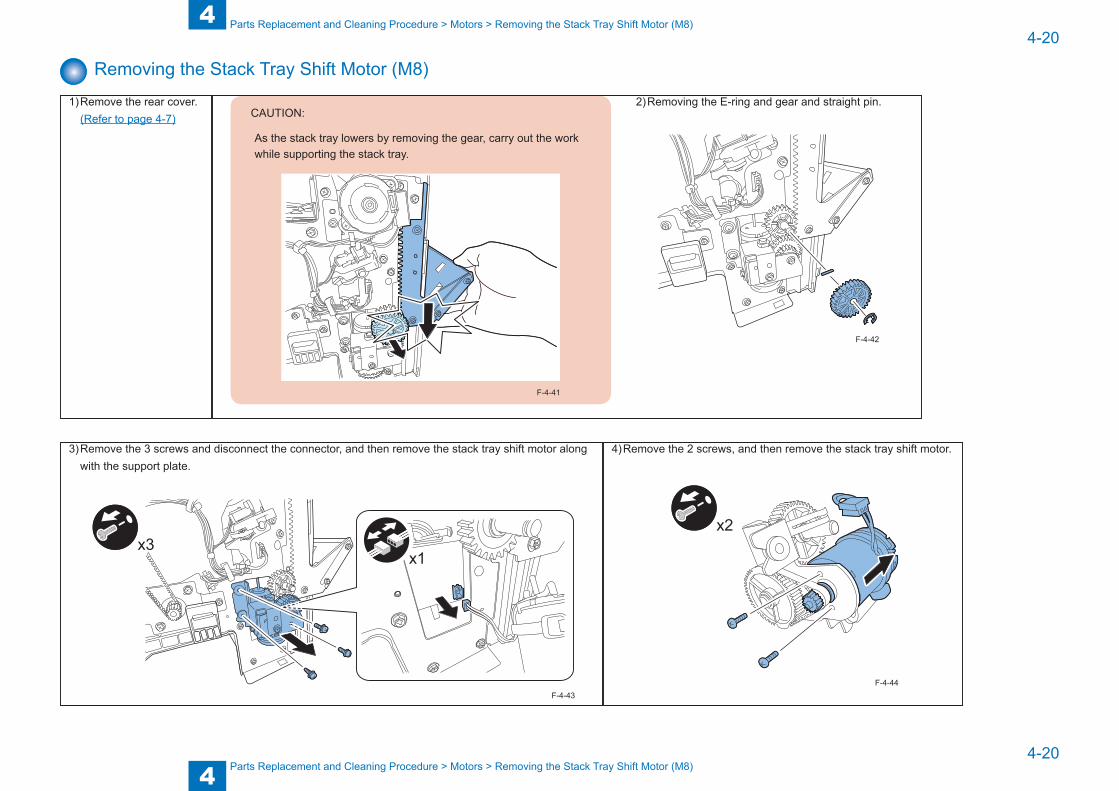
Removing the Stack Tray Shift Motor (M8)
1) Remove the rear cover. (Refer to page 4-7) CAUTION:
As the stack tray lowers by removing the gear, carry out the work while supporting the stack tray.
F-4-41
2) Removing the E-ring and gear and straight pin.
F-4-42
3) Remove the 3 screws and disconnect the connector, and then remove the stack tray shift motor along with the support plate.
x1x3
F-4-43
4) Remove the 2 screws, and then remove the stack tray shift motor.
x2
F-4-44
4
44-21
4-21
Parts Replacement and Cleaning Procedure > Motors > Removing the Stack Tray Shift Motor (M8)
Parts Replacement and Cleaning Procedure > Motors > Removing the Stack Tray Shift Motor (M8)
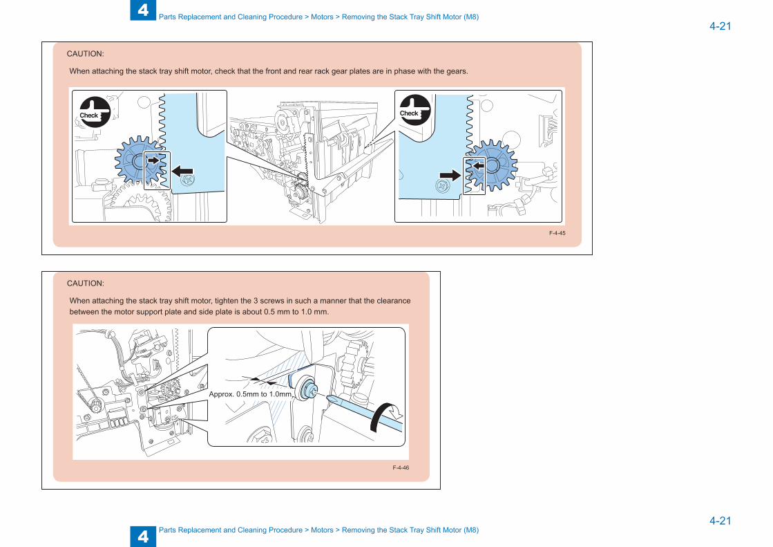
CAUTION:
When attaching the stack tray shift motor, check that the front and rear rack gear plates are in phase with the gears.
F-4-45
CAUTION:
When attaching the stack tray shift motor, tighten the 3 screws in such a manner that the clearance between the motor support plate and side plate is about 0.5 mm to 1.0 mm.
Approx. 0.5mm to 1.0mm
F-4-46
4
44-22
4-22
Parts Replacement and Cleaning Procedure > Switches > Removing the Front Door Switch
Parts Replacement and Cleaning Procedure > Switches > Removing the Front Door Switch
Switches
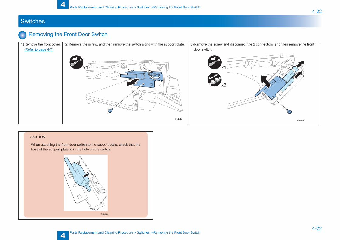
Removing the Front Door Switch
1) Remove the front cover. (Refer to page 4-7)
2) Remove the screw, and then remove the switch along with the support plate.
x1
F-4-47
3) Remove the screw and disconnect the 2 connectors, and then remove the front door switch.
x1
x2
F-4-48
CAUTION:
When attaching the front door switch to the support plate, check that the boss of the support plate is in the hole on the switch.
F-4-49
4
44-23
4-23
Parts Replacement and Cleaning Procedure > Switches > Removing the Stack Tray Lower Limit Switch
Parts Replacement and Cleaning Procedure > Switches > Removing the Stack Tray Lower Limit Switch
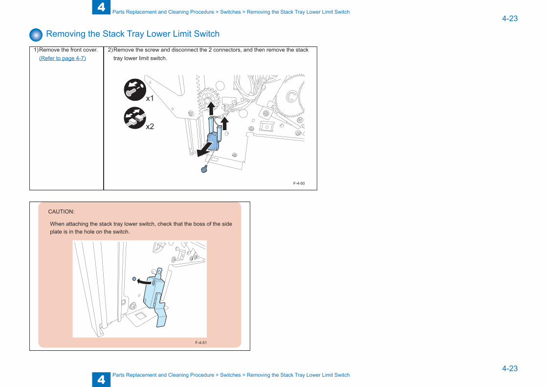
Removing the Stack Tray Lower Limit Switch
1) Remove the front cover. (Refer to page 4-7)
2) Remove the screw and disconnect the 2 connectors, and then remove the stack tray lower limit switch.
x1
x2
F-4-50
CAUTION:
When attaching the stack tray lower switch, check that the boss of the side plate is in the hole on the switch.
F-4-51
4
44-24
4-24
Parts Replacement and Cleaning Procedure > PCBs > Removing the Finisher Controller PCB
Parts Replacement and Cleaning Procedure > PCBs > Removing the Finisher Controller PCB
PCBs
Removing the Finisher Controller PCB
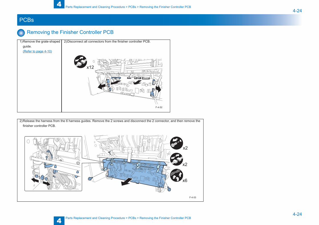
1) Remove the grate-shaped guide.
(Refer to page 4-10)
2) Disconnect all connectors from the finisher controller PCB.
x12
F-4-52
2) Release the harness from the 6 harness guides. Remove the 2 screws and disconnect the 2 connector, and then remove the finisher controller PCB.
x2
x6
x2
F-4-53
5
5 Adjustment
Adjustment ■Adjustment Item ■Dip Switch Function

5
55-2
5-2
Adjustment > Adjustment Item > Overview
Adjustment > Adjustment Item > Overview
Adjustment Item
OverviewThis finisher has no adjustment items.
Sensor detection check and motor operation check can be performed using the DIP switch (SW1), push switch (SW2), and LED (LD1) on the finisher controller PCB.
SW2
SW1LD1
F-5-1
5
55-3
5-3
Adjustment > Dip Switch Function > Sensor Detection Check Mode > List of Sensor Detection Check States
Adjustment > Dip Switch Function > Sensor Detection Check Mode > List of Sensor Detection Check States
Dip Switch Function
Sensor Detection Check Mode ■ Entering the Sensor Detection Check Mode
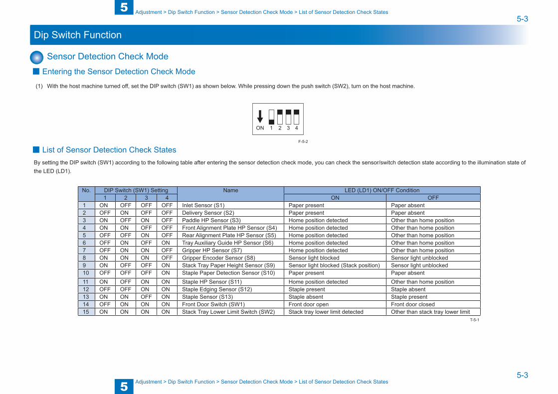
(1) With the host machine turned off, set the DIP switch (SW1) as shown below. While pressing down the push switch (SW2), turn on the host machine.
ON 1 2 3 4
■ List of Sensor Detection Check StatesBy setting the DIP switch (SW1) according to the following table after entering the sensor detection check mode, you can check the sensor/switch detection state according to the illumination state of the LED (LD1).
No. DIP Switch (SW1) Setting Name LED (LD1) ON/OFF Condition1 2 3 4 ON OFF
1 ON OFF OFF OFF Inlet Sensor (S1) Paper present Paper absent2 OFF ON OFF OFF Delivery Sensor (S2) Paper present Paper absent3 ON OFF ON OFF Paddle HP Sensor (S3) Home position detected Other than home position4 ON ON OFF OFF Front Alignment Plate HP Sensor (S4) Home position detected Other than home position5 OFF OFF ON OFF Rear Alignment Plate HP Sensor (S5) Home position detected Other than home position6 OFF ON OFF ON Tray Auxiliary Guide HP Sensor (S6) Home position detected Other than home position7 OFF ON ON OFF Gripper HP Sensor (S7) Home position detected Other than home position8 ON ON ON OFF Gripper Encoder Sensor (S8) Sensor light blocked Sensor light unblocked9 ON OFF OFF ON Stack Tray Paper Height Sensor (S9) Sensor light blocked (Stack position) Sensor light unblocked10 OFF OFF OFF ON Staple Paper Detection Sensor (S10) Paper present Paper absent11 ON OFF ON ON Staple HP Sensor (S11) Home position detected Other than home position12 OFF OFF ON ON Staple Edging Sensor (S12) Staple present Staple absent13 ON ON OFF ON Staple Sensor (S13) Staple absent Staple present14 OFF ON ON ON Front Door Switch (SW1) Front door open Front door closed15 ON ON ON ON Stack Tray Lower Limit Switch (SW2) Stack tray lower limit detected Other than stack tray lower limit
F-5-2
T-5-1
5
55-4
5-4
Adjustment > Dip Switch Function > Motor Operation Check Mode > List of Motor Operation Check States
Adjustment > Dip Switch Function > Motor Operation Check Mode > List of Motor Operation Check States
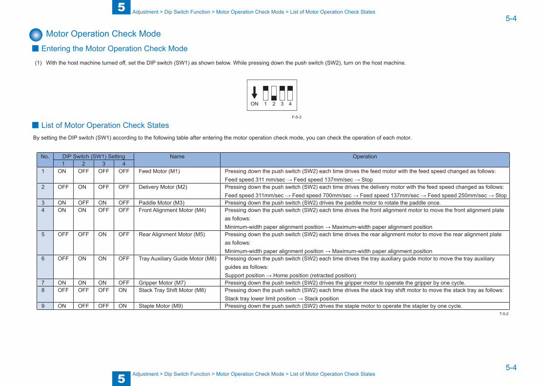
Motor Operation Check Mode ■ Entering the Motor Operation Check Mode
(1) With the host machine turned off, set the DIP switch (SW1) as shown below. While pressing down the push switch (SW2), turn on the host machine.
ON 1 2 3 4
■ List of Motor Operation Check StatesBy setting the DIP switch (SW1) according to the following table after entering the motor operation check mode, you can check the operation of each motor.
No. DIP Switch (SW1) Setting Name Operation1 2 3 4
1 ON OFF OFF OFF Feed Motor (M1) Pressing down the push switch (SW2) each time drives the feed motor with the feed speed changed as follows:Feed speed 311 mm/sec → Feed speed 137mm/sec → Stop
2 OFF ON OFF OFF Delivery Motor (M2) Pressing down the push switch (SW2) each time drives the delivery motor with the feed speed changed as follows:Feed speed 311mm/sec → Feed speed 700mm/sec → Feed speed 137mm/sec → Feed speed 250mm/sec → Stop
3 ON OFF ON OFF Paddle Motor (M3) Pressing down the push switch (SW2) drives the paddle motor to rotate the paddle once.4 ON ON OFF OFF Front Alignment Motor (M4) Pressing down the push switch (SW2) each time drives the front alignment motor to move the front alignment plate
as follows:Minimum-width paper alignment position → Maximum-width paper alignment position
5 OFF OFF ON OFF Rear Alignment Motor (M5) Pressing down the push switch (SW2) each time drives the rear alignment motor to move the rear alignment plate as follows:Minimum-width paper alignment position → Maximum-width paper alignment position
6 OFF ON ON OFF Tray Auxiliary Guide Motor (M6) Pressing down the push switch (SW2) each time drives the tray auxiliary guide motor to move the tray auxiliary guides as follows:Support position → Home position (retracted position)
7 ON ON ON OFF Gripper Motor (M7) Pressing down the push switch (SW2) drives the gripper motor to operate the gripper by one cycle.8 OFF OFF OFF ON Stack Tray Shift Motor (M8) Pressing down the push switch (SW2) each time drives the stack tray shift motor to move the stack tray as follows:
Stack tray lower limit position → Stack position9 ON OFF OFF ON Staple Motor (M9) Pressing down the push switch (SW2) drives the staple motor to operate the stapler by one cycle.
F-5-3
T-5-2
5
55-5
5-5
Adjustment > Dip Switch Function > Tray Auxiliary Guide Operation ON/OFF Setting when delivering a sheet of paper
Adjustment > Dip Switch Function > Tray Auxiliary Guide Operation ON/OFF Setting when delivering a sheet of paper
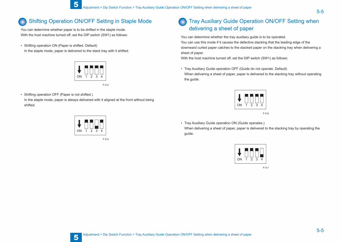
Shifting Operation ON/OFF Setting in Staple ModeYou can determine whether paper is to be shifted in the staple mode.With the host machine turned off, set the DIP switch (SW1) as follows:
• Shifting operation ON (Paper is shifted. Default)In the staple mode, paper is delivered to the stack tray with it shifted.
ON 1 2 3 4
• Shifting operation OFF (Paper is not shifted.)In the staple mode, paper is always delivered with it aligned at the front without being shifted.
ON 1 2 3 4
F-5-4
F-5-5
Tray Auxiliary Guide Operation ON/OFF Setting when delivering a sheet of paper
You can determine whether the tray auxiliary guide is to be operated.You can use this mode if it causes the defective stacking that the leading edge of the downward curled paper catches to the stacked paper on the stacking tray when delivering a sheet of paper.With the host machine turned off, set the DIP switch (SW1) as follows:
• Tray Auxiliary Guide operation OFF (Guide do not operate. Default)When delivering a sheet of paper, paper is delivered to the stacking tray without operating the guide.
ON 1 2 3 4
• Tray Auxiliary Guide operation ON (Guide operates.)When delivering a sheet of paper, paper is delivered to the stacking tray by operating the guide.
ON 1 2 3 4
F-5-6
F-5-7

Blank Page
6
6 Installation
Installation ■How to Utilize This Installation Procedure ■Unpacking Procedure ■Installation Procedure
6
66-2
6-2
How to Utilize This Installation Procedure
How to Utilize This Installation Procedure
How to Utilize This Installation Procedure
Descriptions Used in This ProcedureIn this procedure, the machine connected to the finisher is called the host machine.
When Using the Contained Parts (Bundled Components in the Shipping Carton)
After unpacking, confirm the parts contained in the package.The below symbol appears on the illustration of some steps when the parts contained in the shipping carton are to be used. Mind this symbol to be aware the parts contained in the shipping carton are to be used.
F-6-1
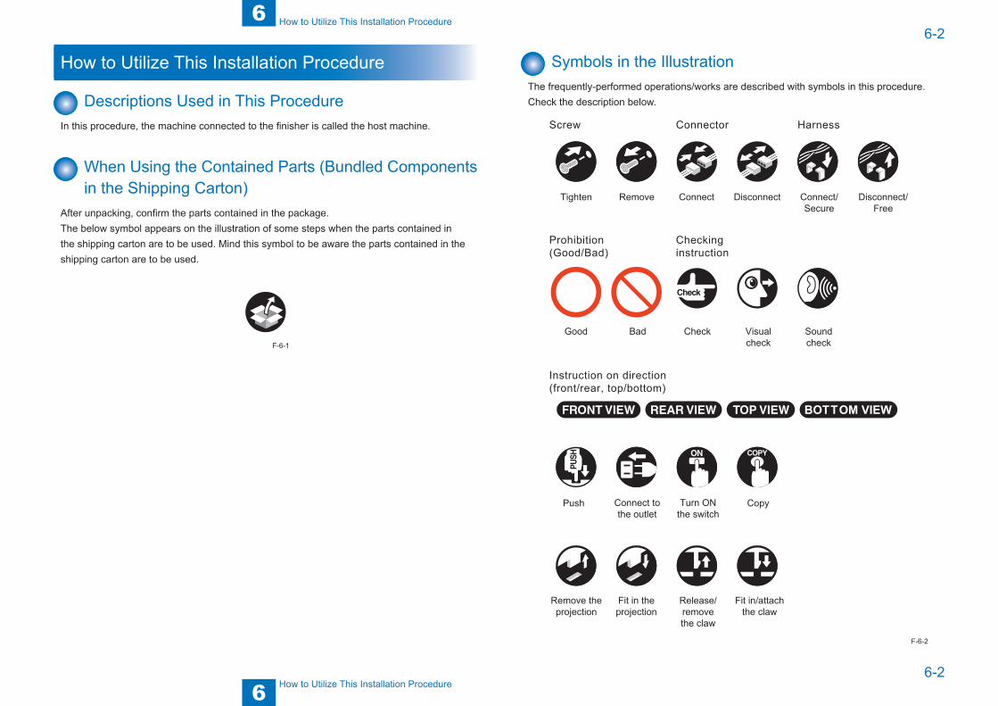
Symbols in the IllustrationThe frequently-performed operations/works are described with symbols in this procedure. Check the description below.
Tighten Connect
Connector Harness
Good
Connect tothe outlet
Remove theprojection
Release/removethe claw
Fit in/attachthe claw
Turn ONthe switch
Push Copy
Bad Check Visualcheck
Disconnect Connect/Secure
Disconnect/Free
Remove
Soundcheck
Instruction on direction (front/rear, top/bottom)
Prohibition (Good/Bad)
Screw
Checking instruction
Fit in theprojection
F-6-2
6
66-3
6-3
Installation > Unpacking Procedure > Unpacking Procedure
Installation > Unpacking Procedure > Unpacking Procedure
Unpacking Procedure
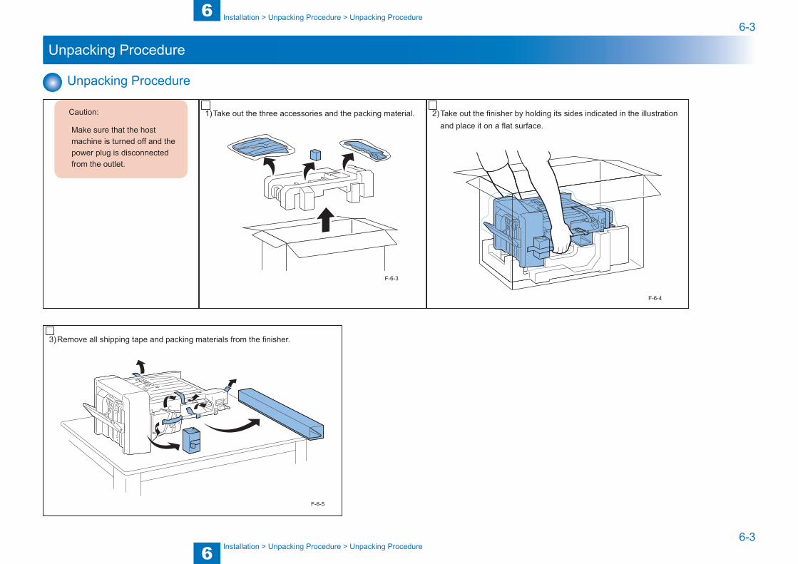
Unpacking Procedure
Caution:
Make sure that the host machine is turned off and the power plug is disconnected from the outlet.
1) Take out the three accessories and the packing material.
F-6-3
2) Take out the finisher by holding its sides indicated in the illustration and place it on a flat surface.
F-6-4
3) Remove all shipping tape and packing materials from the finisher.
F-6-5
6
66-4
6-4
Installation > Installation Procedure > Preparation for Installation on Host Machine
Installation > Installation Procedure > Preparation for Installation on Host Machine
Installation Procedure
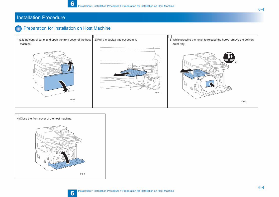
Preparation for Installation on Host Machine
1) Lift the control panel and open the front cover of the host machine.
F-6-6
2) Pull the duplex tray out straight.
F-6-7
3) While pressing the notch to release the hook, remove the delivery outer tray.
x1
F-6-8
4) Close the front cover of the host machine.
F-6-9
6
66-5
6-5
Installation > Installation Procedure > Connecting to Host Machine
Installation > Installation Procedure > Connecting to Host Machine
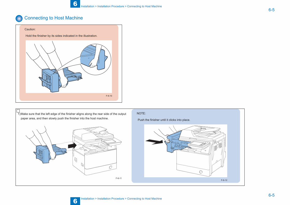
Connecting to Host Machine
Caution:
Hold the finisher by its sides indicated in the illustration.
F-6-10
1) Make sure that the left edge of the finisher aligns along the rear side of the output paper area, and then slowly push the finisher into the host machine.
F-6-11
NOTE:
Push the finisher until it clicks into place.
F-6-12
6
66-6
6-6
Installation > Installation Procedure > Connecting to Host Machine
Installation > Installation Procedure > Connecting to Host Machine
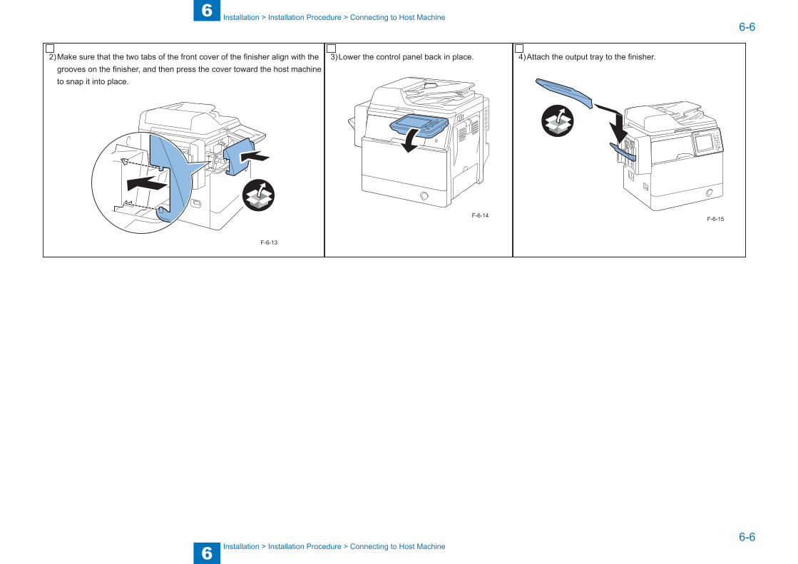
2) Make sure that the two tabs of the front cover of the finisher align with the grooves on the finisher, and then press the cover toward the host machine to snap it into place.
F-6-13
3) Lower the control panel back in place.
F-6-14
4) Attach the output tray to the finisher.
F-6-15

7
Appendix
Appendix ■Service Tools ■General Circuit Diagram

77-2
7-2
Appendix > Service Tools > Solvents and Oils
Appendix > Service Tools > Solvents and Oils
Service Tools
Solvents and OilsNo. Item Uses Composition Remarks
1 Alcohol Cleaning;e.g., glass, plastic, rubber parts, external covers.
Fluoride-family hydrocarbonAlcoholSurface activating agentWater
• Do not bring near fire.• Procure locally• Substitute: IPA (isopropyl alcohol)
2 Solvent Cleaning;e.g., metal, oil or toner stain.
Fluoride-family hydrocarbonChlorine-family hydrocarbonAlcohol
• Do not bring near fire.• Procure locally• Substitute: MEK
3 Lubricating oil Lubrication;e.g., drive areas, friction areas.
Silicone oil • Tool No.: FY9-6022
T-7-1
77-3
7-3
Appendix > Service Tools > Solvents and Oils > Applying the Grease
Appendix > Service Tools > Solvents and Oils > Applying the Grease
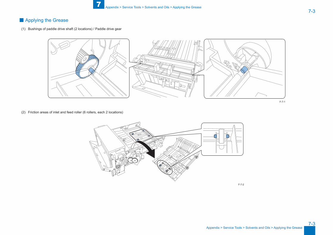
■ Applying the Grease
(1) Bushings of paddle drive shaft (2 locations) / Paddle drive gear
(2) Friction areas of inlet and feed roller (6 rollers, each 2 locations)
F-7-1
F-7-2
77-4
7-4
Appendix > Service Tools > Solvents and Oils > Applying the Grease
Appendix > Service Tools > Solvents and Oils > Applying the Grease
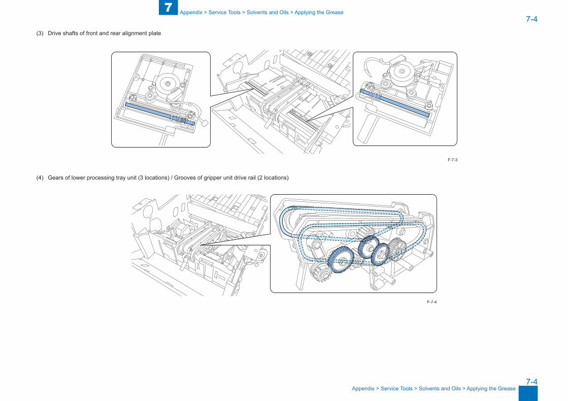
(3) Drive shafts of front and rear alignment plate
(4) Gears of lower processing tray unit (3 locations) / Grooves of gripper unit drive rail (2 locations)
F-7-3
F-7-4
77-5
7-5
Appendix > Service Tools > Special Tools
Appendix > Service Tools > Special Tools
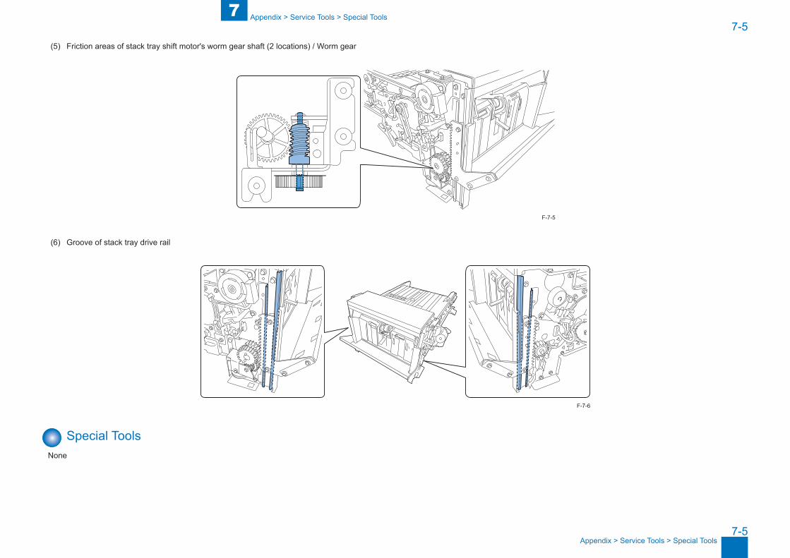
(5) Friction areas of stack tray shift motor's worm gear shaft (2 locations) / Worm gear
(6) Groove of stack tray drive rail
Special ToolsNone
F-7-5
F-7-6

7-6
7-6
App
endi
x >
Gen
eral
Circ
uit D
iagr
am >
Gen
eral
Circ
uit D
iagr
am
App
endi
x >
Gen
eral
Circ
uit D
iagr
am >
Gen
eral
Circ
uit D
iagr
am
General Circuit Diagram
General Circuit Diagram
J3P3
CN
1
J1P1
A1 9A2 8A3 7A4 6
GNDRXDTXD
A5 5 GNDB1 4B2 3B3 2B4 1
2 23 3
FIN_ENAFIN_RESFIN_DOWNLOADFIN_DETECT
4 4
GND24V
GND5V
J2
P2-13
P2
P2-12 1 1
COM
NO1 2
24V OUT
24V IN
J14
P14
P14-1
P14-2
COM
NC
1 1
1 3
P14
-3
1 5
2 6+ 1 J14-
3
- 2
J7
2 1
J7-1
P7
P7-
1
P7-
11
3 14 26 3
2 21 3
P7-1
2
J7-2
8 1
12 3 P7-2
3 12 21 3
11 1
P7-
59 27 3
17 4
J7-6
P7-
6 P7-
1415 513 6
3 12 21 3
INGND
VCC-R
J5 P5
P5-
1
2 14 26 38 4
10 1
P5-
2
INGND
VCC-R
INGND
VCC-R
INGND
VCC-R
12 3
10 2
14 416 6
7 15 23 31 4 P5
-3
15 113 211 39 4 P5
-4
A/ A/ BB
A/ A/ BB
A/ A/ BB
A/ A/ BB
P8-
11
P8-
1
1 3
J8-1
1 2
P8 J8
2 23 1
2 43 6
INGNDVCC-R
P8-1
2
P8-2
1 32 23 1 J8
-2
1 82 103 12
INGNDVCC-R
P8-
3
1 52 33 1
STK DN 24V OUT
STK DN 24V IN
INGNDVCC-R
INGNDVCC-RP
8-4
1 112 93 7
P13
-1
P13 J13
INGNDVCC-R
1 12 23 3
J11
P11
P11
-1
1 12 23 3
VCCINGND
J6P6
P6-
1
+ 1 J6-3
- 2
P6-2
P6-
3
1 12 23 34 4
A/ A/ BB
A/ A/ BB
1 52 63 74 8
1 9
2 10
J10
P10
J9P9
P10
-1P
9-1
GNDSTP LOWSTP READYSTP HOMEVCC
1 12 23 34 45 5
1 12 2
3 34 4
J4J1
7
1 1
M
M
M
M
M
M
M
M
M
F i n i s h e r C o n t r o l l e r P C B
T o H o s t M a c h i n e
S W 1F r o n t D o o r S w i t c h
S W 2S t a c k T r a y L o w e rL i m i t S w i t c h
M 8S t a c k T r a yS h i f t M o t o r
M 1F e e d M o t o r
M 2D e l i v e r y M o t o r
M 5R e a r A l i g n m e n t M o t o r
M 3P a d d l e M o t o r
S 2D e l i v e r y S e n s o r
S 1I n l e t S e n s o r
S 7G r i p p e r H P S e n s o r
S 9S t a c k T r a y P a p e rH e i g h t S e n s o r
S 6T r a y A u x i l i a r y G u i d eH P S e n s o r
S 4F r o n t A l i g n m e n t P l a t e H P S e n s o r
S 3P a d d l e H P S e n s o r
S 8G r i p p e r E n c o d e r S e n s o r
S 1 0S t a p l e P a p e r D e t e c t i o n S e n s o r
M 6T r a y A u x i l i a r y G u i d e M o t o r
M 4F r o n t A l i g n m e n t M o t o r
M 7G r i p p e r M o t o r
M 9S t a p l e M o t o r
S 1 1S t a p l e H P S e n s o r
S 1 2S t a p l e E d g i n g S e n s o r
S 1 3S t a p l e S e n s o r
S 5R e a r A l i g n m e n t P l a t e H P S e n s o r
S t a p l e U n i tF-7-7