industrial power resistors neutral earthing dynamic ... · removable undrilled gland plate. a low...
TRANSCRIPT

Neutral Earthing
Dynamic Braking
Harmonic Filters
Portable Load Units
Load Banks
Motor Control
INDUSTRIAL
POWER
RESISTORS

2
WHY SPECIFY CRESSALL RESISTORS?

3
THE WORLD’S FOREMOST RESISTOR MANUFACTURER, CRESSALL RESISTORS OFFER ANUNRIVALLED COMBINATION OF EXPERIENCE AND THE WIDEST RANGE OF RESISTOR TECHNOLOGIES.
Cressall Resistors have almost 100 years experience of
producing power resistors for use in the electro-technical
market. With design and manufacturing facilities at two
locations in the UK, Cressall can supply both standard and
custom-designed resistor solutions for any application
from a few watts up to several megawatts and for
operation at any voltage.
With more than 100 employees at facilities in
Leicester and Melton Constable, our qualified
engineers will advise you on the most suitable and
competitive design for your requirements.
A quality management system approved to
ISO9001 combined with the continuous develop-
ment of our products and the people that provide them
ensure that the service we offer is second to none.
Cressall is part of the resistor division of Halma plc, a
British public company with an outstanding track record
of growth.
With sister companies and distributors around the world
Cressall can provide global customer service.
Details of our sister companies and distributors can be
found on our website www.cressall.com.

4
WHY SPECIFY CRESSALL RESISTORS?
Cressall reliabilityCressall products are well-proven in the most arduous
and demanding environments such as found in steel works,
chemical plants and oil rigs.
Versatile technologyThe broad range of Cressall resistor elements provides the
versatility required to offer solutions for any application.
Resistors can be specified for any combination of
resistance value, temperature rise, duty cycle, current and
voltage rating.
Product development and innovationCressall’s range of resistor elements are subject to
a process of continuous research, development and
product innovation.

5
Neutral Earthing 6
Earth Fault Detection 11
Dynamic Braking 12
Harmonic Filters 18
Portable Load Units 20
Static Load Banks 22
Expanded Mesh 24
Edgewound 26
RP Coils 27
ZO Coils 28
ZC Coils 29
CS Coils 30
Service Grids 31
Wirewound 32
GP Coils 33
CC Coils 34
www.cressall.com
Recent developments include:• The acquisition of Eaton Cutler Hammer’s
resistor business
• The integration of the GEC Alsthom resistor range
• The introduction of a standard range of stock
braking resistors
• A new coiled-coil resistor range
• Extending the range of portable load units
Fast responseWhatever your resistor requirements our team of
qualified engineers and production staff will offer a fast,
cost-effective solution and deliver a service that is second
to none.
This commitment extends through every stage of the
process, from initial enquiry to after-sales support.
Quality controlCressall Resistors has produced
products under a quality control
system, approved to ISO9001.

6
NEUTRALEARTHING
NEUTRAL EARTHING
The rating of an NER is chosen to meet the
requirements of the system protection scheme;
this will include consideration of maximum
acceptable fault current, earth potential levels,
and preventing damage caused by the fault.
Cressall neutral earthing resistors (NERs) are
employed in AC distribution networks to limit
the current that would flow through the neutral
point of a transformer or generator in the event
of an earth fault.
www.cressall.com
Resistors rated 77kV, 400A for 15seconds supplied by Cressall are beingused in domestic Japanese substations.

7
www.cressall.com
ChoiceAn extensive range of metal resistor elements
allows selection of the most efficient and cost
effective solution for any required duty. Cressall
can manufacture NERs for any system voltage
and initial current with rated times from a few
seconds to continuous.
Stability and predictabilityThe resistance value is set at the manufacturing
stage and remains constant throughout the life
of the NER. Unlike liquid resistors, changes in
resistance value due to the fluctuations in ambi-
ent temperature are negligible. This means that
protection levels can be accurately pre-deter-
mined.
In contrast to an earthing reactor, a Cressall NER
does not induce phase changes or resonances
into the fault current and does not require match-
ing to the associated transformer.
Rapid cooling and short time ratingsModern protection systems typically clear faults
in less than a second. However, the time rating
of an NER usually needs to cater for the possi-
bility of several successive faults.
Cressall resistors cool down much faster than
liquid resistors after operation. To cater for
successive faults liquid resistors have longer time
ratings, typically 30 seconds, as opposed to 10
seconds for metallic resistors.
Ease of installationCressall NERs are compact and do not require
site calibration or auxiliary power supplies.
Low operating costsFixed resistance values mean that maintenance
is limited to periodic inspection and cleaning.
Anti-frost and anti-condensation heaters are not
generally required.
ReliabilityNERs may only be called upon to operate a few
times in their service life, which may be 25 years
or more. Cressall NERs have been proven reli-
able in numerous installations and under severe
climatic conditions world-wide.
CRESSALL NERS HAVE NUMEROUS BENEFITS:Neutral Earthing
Earth Fault Detection 11
Dynamic Braking 12
Harmonic Filters 18
Portable Load Units 20
Static Load Banks 22
Expanded Mesh 24
Edgewound 26
Service Grids 31
Wirewound 32

8
Construction
StandardsAt present the only standard for NERs is ANSI/
IEEE Std 32, 1972. Cressall NERs can be designed
and tested to comply with this standard, or with
individual client specifications.
Resistor elementsFor the majority of ratings the most suitable
element is the type RP oval edge-wound coil.
RP resistors are manufactured from a continu-
ous stainless steel strip, wound edgewise into
oval coils. Each coil is supported by ridged
ceramic insulators mounted on a stainless steel
centre support, with stainless steel terminals
welded at each end. This arrangement allows free
expansion and contraction at operating tempera-
tures up to 1100°C without imposing strain on
the assembly.
The resistance alloys used are high temperature
stainless steels capable of withstanding tem-
perature excursions to 1100°C whilst retaining
their strength, unlike 304 or other structural
grade stainless steels which are limited to much
lower temperatures.
NERs designed for operation to higher tempera-
tures require less active mass, resulting in more
compact and economical designs.
Temperature coefficient of resistanceUnlike structural grade stainless steels the tem-
perature coefficient of the material used ensures
a resistance increase of less than 3.5% per 100°Crise over the operating temperature range.
Resistor banksThe end insulators of individual resistor elements
are clamped and locked on to tie-rods. Any
element can be removed without disturbing the
remainder.
The tie-rods are supported between galvanised
end-plates to form banks. These banks can be
mounted on top of each other with intermediate
insulators to form a complete self-supporting
stack.
Interconnections between coils are copper,
using two bolts per joint.
Enclosure protection ratingsThe standard enclosure is designed to IP23 to
IEC529 (to prevent the ingress of foreign bodies
greater than 12mm, and rain falling at any angle
up to 60° from the vertical). This rating is suit-
able for indoor or outdoor use as it allows suffi-
cient cooling and provides more than adequate
protection unless the environmental conditions
are extreme. Protection ratings above IP23 are
rarely needed because Cressall resistor stacks
are virtually corrosion proof and immune from
progressive pitting and rusting. The operation of
the resistor and the ceramic insulators are not
affected by exposure to condensation, sand or
fine dust, provided that the dust is not unduly
conductive.
If higher degrees of protection are specified,
these can be provided (up to IP55). It should be
realised that the operational penalty of using less
well ventilated enclosures is that the external
surfaces will become hotter and cooling times
will be longer.
Enclosure materials and finishEnclosures are manufactured as standard from
unpainted stainless steel. This ensures better and
more economic long term corrosion protection
than galvanised or painted mild steel units.
If required other enclosure materials and
special finishes can be supplied to comply with
users’ specifications.
NEUTRALEARTHING www.cressall.com
9
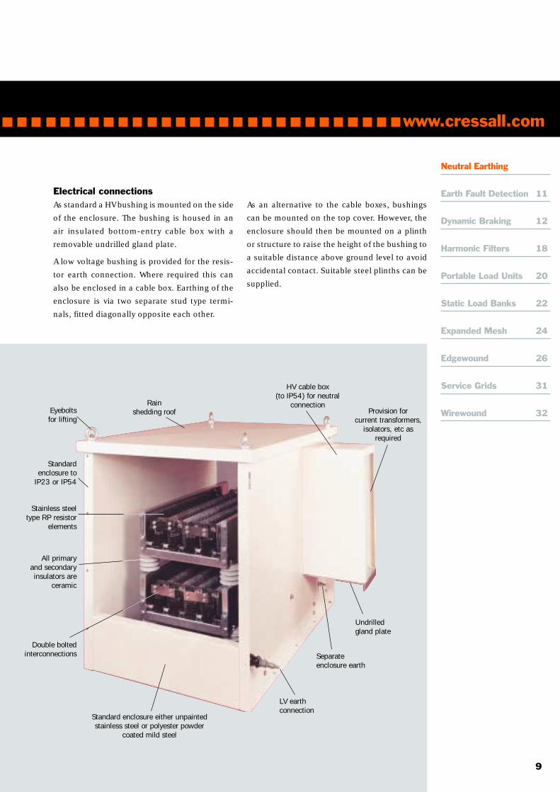
Rainshedding roofEyebolts
for lifting
HV cable box(to IP54) for neutral
connectionProvision for
current transformers,isolators, etc as
required
Undrilledgland plate
Separateenclosure earth
All primaryand secondaryinsulators are
ceramic
Double boltedinterconnections
Stainless steeltype RP resistor
elements
Standardenclosure to
IP23 or IP54
LV earthconnection
Standard enclosure either unpaintedstainless steel or polyester powder
coated mild steel
Electrical connectionsAs standard a HV bushing is mounted on the side
of the enclosure. The bushing is housed in an
air insulated bottom-entry cable box with a
removable undrilled gland plate.
A low voltage bushing is provided for the resis-
tor earth connection. Where required this can
also be enclosed in a cable box. Earthing of the
enclosure is via two separate stud type termi-
nals, fitted diagonally opposite each other.
As an alternative to the cable boxes, bushings
can be mounted on the top cover. However, the
enclosure should then be mounted on a plinth
or structure to raise the height of the bushing to
a suitable distance above ground level to avoid
accidental contact. Suitable steel plinths can be
supplied.
www.cressall.com
Neutral Earthing
Earth Fault Detection 11
Dynamic Braking 12
Harmonic Filters 18
Portable Load Units 20
Static Load Banks 22
Expanded Mesh 24
Edgewound 26
Service Grids 31
Wirewound 32

10
NEUTRALEARTHING
Other equipmentWhere required cable boxes can house current
transformers, isolators, vacuum contactors or
other ancillary equipment.
Standard testsAs standard, NERs are tested to the requirements
of ANSI/IEEE Std 32, 1972.
Routine tests on all units include:
• Dimensional check to relevant drawing
• Resistance measurement at ambient
temperature
• One minute power frequency withstand test
to levels specified in ANSI/IEEE Std 32, 1972
typically (2.25 x line voltage) +2kV
Temperature rise type tests have been carried out
on a range of typical ratings for both 760°C (in
accordance with ANSI/IEEE Std 32, 1972) and
1000°C. Copies of these results are available.
www.cressall.com
NER rated 11kV, 625A for 10 secondsinstalled in a substation near Heathrow.
Transformer mounted NER rated11kV, 1000A for 10 seconds.
11
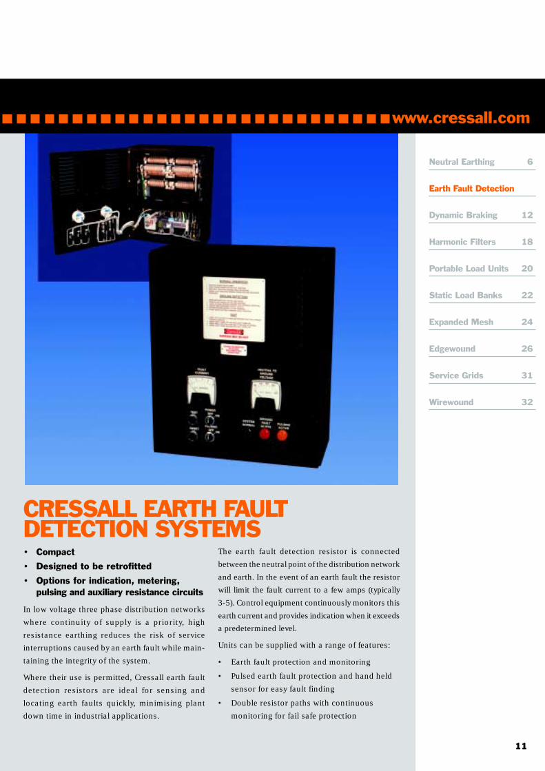
The earth fault detection resistor is connected
between the neutral point of the distribution network
and earth. In the event of an earth fault the resistor
will limit the fault current to a few amps (typically
3-5). Control equipment continuously monitors this
earth current and provides indication when it exceeds
a predetermined level.
Units can be supplied with a range of features:
• Earth fault protection and monitoring
• Pulsed earth fault protection and hand held
sensor for easy fault finding
• Double resistor paths with continuous
monitoring for fail safe protection
• Compact
• Designed to be retrofitted
• Options for indication, metering,pulsing and auxiliary resistance circuits
In low voltage three phase distribution networks
where continuity of supply is a priority, high
resistance earthing reduces the risk of service
interruptions caused by an earth fault while main-
taining the integrity of the system.
Where their use is permitted, Cressall earth fault
detection resistors are ideal for sensing and
locating earth faults quickly, minimising plant
down time in industrial applications.
www.cressall.com
CRESSALL EARTH FAULTDETECTION SYSTEMS
Neutral Earthing 6
Earth Fault Detection
Dynamic Braking 12
Harmonic Filters 18
Portable Load Units 20
Static Load Banks 22
Expanded Mesh 24
Edgewound 26
Service Grids 31
Wirewound 32
12
DYNAMIC BRAKINGDYNAMICBRAKING
Cressall is one of the leading suppliers of
dynamic braking resistors to OEMs, integrators,
users and distributors of AC variable
frequency drives.
Cressall DBRs are used to stop motors or to
produce a braking torque in the motor during
overhauling load conditions. The dynamic
braking resistor is connected across the DC bus
and can see voltages as high as 1100 volts
(Cressall DBRs can be insulated and rated for
higher voltages if required).
The resistance value determines the amount of
braking torque produced and thus the rate at which
the motor will stop, the lower the resistance the
higher the braking torque and the quicker the stop.
Drive manufacturers will specify a minimum
resistance value to ensure that the braking
capacity of the drive is not exceeded. As standard
Cressall manufacture DBRs with a –0/+10%
tolerance to ensure optimum performance (other
values can be achieved if required).
When sizing brake resistors, key parameters for
consideration are resistance value, braking power
and the duration and frequency of the stop.
www.cressall.com
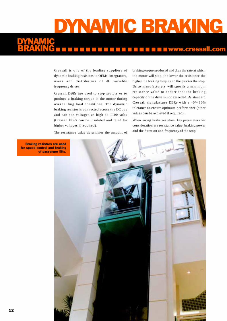
Braking resistors are usedfor speed control and braking
of passenger lifts.

13
ConstructionManufactured using electrical grade alloys,
resistor elements are either type ‘ZC’ (coiled
strip) ‘CC’ (coiled coil) or ‘SD’ (expanded mesh).
Units can be supplied as loose elements, open
banks or housed in ventilated enclosures.
Type CC coiled coil resistors• Medium to high resistance value
• Rapid duty cycle
• High overload capacity
Type ZC edgewound strip• Low to medium resistance value
• High power intermittent duty
• High overload capacity
Type SD expanded mesh• Low resistance value
• High continuous power
• Rapid duty cycle
www.cressall.com
Neutral Earthing 6
Earth Fault Detection 11
Dynamic Braking
Harmonic Filters 18
Portable Load Units 20
Static Load Banks 22
Expanded Mesh 24
Edgewound 26
Service Grids 31
Wirewound 32

14
A DBR used for hoistapplication undergoes finaltesting before installation.
Standard dynamic braking resistorsTo meet the requirements of the market Cressall
have developed a range of standard DBRs
designed to cater for the most common applica-
tions. Depending on rating these units can be
manufactured from stock components or (for the
most popular sizes) supplied direct from stock.
As standard Cressall DBRs are housed in plated
mild steel enclosures affording ingress protec-
tion to IP20 or IP21. They include a built-in
terminal box, terminal block and high tempera-
ture wiring. A normally closed thermal switch is
fitted as standard. Units may be wall or roof
mounted as required.
• Most common sizes availablefrom stock
• Easily installed
• Suitable for all ranges of drives
• Suitable for any power or duty cycle
• Insulated for operation at 800V
• Thermal trip fitted as standard
• CE marked
DYNAMICBRAKING www.cressall.com

15
Designed for easy panel mounting,DBRs are used in a range of industriessuch as food processing and lift control.
www.cressall.com
Neutral Earthing 6
Earth Fault Detection 11
Dynamic Braking
Harmonic Filters 18
Portable Load Units 20
Static Load Banks 22
Expanded Mesh 24
Edgewound 26
Service Grids 31
Wirewound 32

16
Standard enclosure dimensionsEnclosure Dimensions (mm)
size H W L A B1 140 102 367 62 302
2 140 180 367 138 302
3 140 179 580 138 514
4 140 179 580 138 514
6 140 179 766 138 700
8 140 330 580 290 514
9 140 255 766 214 700
12 140 330 766 290 700
24 304 335 800
36 429 335 800
DYNAMICBRAKING
Standard ingress protection IP20.
Enclosures have separate terminal compartment and800V rated terminals.
Note! Shaded units indicate standard designs. Otherunits available on request.
For unit performance see relevant colour codedcurve on Rating curves graph.
www.cressall.com
DBR selectionThe Cressall standard range of dynamic
braking resistors (DBR’s) is based on
using four unique element designs
giving an easy selection process.
The rating of each element design
differs and the rating curves below give
a power multiplier based on the duty
cycle.
For 100% (continuous) duties select the
DBR using the max power rating of the
drive/ inverter and the recommended
ohmic value given by the manufacturer.
suounitnoc.xaM)Wk(rewop 5.0 1 5.1 2 3 4 5.4 6 9 21 81
eziserusolcnE 1 2 3 4 6 8 9 21 81 42 63
ecnatsiseR )Ω( )Ω( )Ω( )Ω( )Ω()%01+/0-(
6.1
8.1
2
2.2
4.2
6.2
8.2
3
2.3
6.3
4
5
5.5
6
8.6
5.7
8
01
21
41
51
81
02
22
42
52
82
03
23
63
04
54
05
55
06
86
57
08
001
021
061
002
052
yponaclanoitpO Y Y Y Y Y Y Y Y Y Y Y
Dynamic braking resistors standard range
Refer tofactory
Part numbers: The resistor part number is derived from the enclosure size andresistance value, for the example on the following page we would use a size 6 enclo-sure with a resistance value of 40 ohms, the part number would be DBR6-40R.
Where resistance values include a decimal point this will be represented by the R,for example the part number for a size 12 box with a resistance value of 3.2 ohmswill be DBR12-3R2.

17
Example: The following calculation is based on10 seconds on time.
Drive power 7.5 kW
Resistance 40 ohms (recommended bydrive supplier)
Duty 10 seconds on in 40seconds (25%)
Selection: Use the curves to convert your dutycycle into the equivalent continuous power for thebrake resistor. Providing the resistance value canbe obtained the most cost effective design will bethe smallest.
The 25% example shown allows four conversionfactor options. The designs giving a power multi-plier of 3.2 and 2.9 are only applicable to resis-tors with high continuous power ratings and wouldbe inefficient. The 2.6 and 1.8 power multipliersallow us to select either a 3kW (yellow) or 4kW(green) continuously rated resistor from the stand-ard range. In this instance as the resistance value can be obtained for bothpower ratings the 3kW resistor is smaller and would be the preferred choice.
25%
3
2.5
2
1.5
1
0.5
00 10 20 30
0 10 20 30 40 50 60 70 80 90 100 110
www.cressall.com
Neutral Earthing 6
Earth Fault Detection 11
Dynamic Braking
Harmonic Filters 18
Portable Load Units 20
Static Load Banks 22
Expanded Mesh 24
Edgewound 26
Service Grids 31
Wirewound 32
Cressall DBR rating curves
Duty Cycle % – 10 seconds ON time
Pow
er
Multip
lier
9
8.5
8
7.5
7
6.5
6
5.5
5
4.5
4
3.5
3
2.5
2
1.5
1
0.5
0
2.6

18
HARMONIC FILTERS
Roof mounted damping and dischargeresistors used as part of a relocatableStatic VAr Compensator.
125kV BIL damping resistorsinstalled as part of the upgrade to
the West Coast Main Line.
HARMONICFILTERS
The ever-increasing use of power electronics has
led to a rise in the amount of harmonic voltages
on the power supply network. Harmonics can
have an adverse impact on many electrical
systems and, as such, this makes the aspect of
power quality more and more important for both
suppliers and users of electrical power.
These harmonic voltages can increase line losses
and also have a detrimental effect on other
users of the network.
Harmonics can be reduced to acceptable levels
by passive filter circuits consisting of inductors,
capacitors and resistors. The filter circuit allows
through the fundamental frequency and diverts
the harmonic frequencies to the resistor bank
where they are dissipated as heat and thus lost
from the system.
Low inductance is a key design feature of filter
resistors. The units offered by Cressall have neg-
ligible inductance and are particularly suitable
for operation at high voltages in the following
applications:
Static VAr compensators (SVCs)
HVDC transmission systems
Mechanically switched capacitordamping networks (MSCDNs)
Industrial harmonic filters
Cressall have supplied resistors for use within
filter systems at every level of the electrical
distribution system, from 400kV grid transformers
to 415V industrial equipment, and with power
ratings from a few watts to several megawatts.
www.cressall.com

19
Used by the National GridCompany, these filterresistors are rated 550kVBIL, 500kW per phase.
www.cressall.com
Neutral Earthing 6
Earth Fault Detection 11
Dynamic Braking 12
Harmonic Filters
Portable Load Units 20
Static Load Banks 22
Expanded Mesh 24
Edgewound 26
Service Grids 31
Wirewound 32

20
PORTABLE LOAD UNITS
24-28 DC ModelModel type Voltage Power Steps Continuous Dimensions Weight
(V) (kW) current (A) L x W x H (mm) (kg)DC110 28V 3.3 fully variable 120 400 200 500 10
48-54 DC ModelsModel type Voltage Power Steps Continuous Dimensions Weight
(kW) current (A) L x W x H (mm) (kg)DC70 50V 3.5 fully variable 70 400 200 500 10
DC120 50V 6.0 fully variable 120 540 310 495 15
DC220 50V 11.0 fully variable 210 540 310 500 15
DC600 50V 30.0 fully variable 600 560 400 840 40
Units are each supplied with a pair of leads
AC ModelModel type Voltage Power Steps Continuous Dimensions Weight
(V) (kW) W(A) current (A) L x W x H (mm) (kg)AC30* 240, 1Ø 15 333(1.4) 62.5 560 400 840 30
415, 3Ø 30 333(1.4) 41.6
* AC30 supplied as standard with one three-phase lead and connector; single-phase lead optional
• Fully variable current setting
• Cooling fan driven by test load
• Shunt for current measurement
with 4mm banana sockets (all
units except DC600)
• Full power at two voltages
in a single unit
• DIN 48mm voltmeter, ammeter
and separate 1.5% shunt
• Cooling fan driven by test load
• Ability to set unbalanced loads
• Input connectors to
BS4343/DIN49462
• Single phase ac or dc operation
• Contactor switched
• Fans and contactors driven by
external 110V or 230V ac supply
• Illuminated switches
• Single and three phase operation in one unit
• DIN 48mm voltmeter, ammeter and
frequency meter
PORTABLELOAD UNITS
AC/DC ModelsModel type Voltage Power Steps Continuous Dimensions Weight
(V ac or dc) (kW) W(A) current (A) L x W x H (mm) (kg)Dual30 (120/240) 120 31.5 500(4) 262 600 500 800 50
240 31.5 500(2) 131
Dual30 (240/480) 240 31.5 500(2) 131 600 500 800 50
480 31.5 500(1) 65
Units are each supplied with a pair of leads
www.cressall.com

21
Cressall’s range of standard units is designed for
testing ac and dc systems, including batteries,
uninterruptible power supplies (UPSs) and stand-
by generators.
All units are fan-cooled, which helps to ensure a
compact design. The fan supply is taken from the
test load itself or from an auxiliary supply of 110
or 230V ac, according to model.
Units are fitted with over temperature protection.
To reduce weight enclosures are manufactured
from aluminium and fitted with handles and
where required have castors to ease manoeu-
vrability. Load banks are supplied with one
cable and connector.
DC and AC/DC models can be operated at voltages
lower than their nominal rating. Power is reduced
accordingly.
www.cressall.com
Neutral Earthing 6
Earth Fault Detection 11
Dynamic Braking 12
Harmonic Filters 18
Portable Load Units
Static Load Banks 22
Expanded Mesh 24
Edgewound 26
Service Grids 31
Wirewound 32
22
STATIC LOAD BANKS
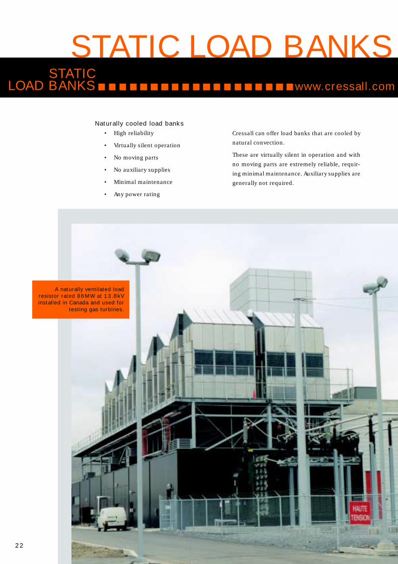
A naturally ventilated loadresistor rated 86MW at 13.8kVinstalled in Canada and used for
testing gas turbines.
Cressall can offer load banks that are cooled by
natural convection.
These are virtually silent in operation and with
no moving parts are extremely reliable, requir-
ing minimal maintenance. Auxiliary supplies are
generally not required.
STATICLOAD BANKS
Naturally cooled load banks• High reliability
• Virtually silent operation
• No moving parts
• No auxiliary supplies
• Minimal maintenance
• Any power rating
www.cressall.com

23
Rated 7MW at 13.8kV this forcecooled load resistor is used fortesting generators in Germany.
Force cooled load banks• Compact design
• Cost effective
• Optional infra-red thermal protection
• Any power rating
Cressall can offer force cooled load units. At
higher powers these provide a cost effective and
compact alternative to naturally cooled units.
Acoustic attenuation can be provided to meet
specified noise levels. Units are supplied with
thermal sensors and air pressure switches for
protection.
All units can be supplied with switchgear and
instrumentation if required.
Force cooling or natural ventilation
Suitable for any power and any voltage (ac or dc)
Single or multiple sections
www.cressall.com
Neutral Earthing 6
Earth Fault Detection 11
Dynamic Braking 12
Harmonic Filters 18
Portable Load Units 20
Static Load Banks
Expanded Mesh 24
Edgewound 26
Service Grids 31
Wirewound 32

24
VersatilityCressall engineers can select expanded mesh with
any configuration of element length, cross-section,
material thickness, banking arrangement and
cooling method to suit the requirements of the
application.
Expanded mesh resistors can be made from any
suitable resistance material. As standard Nickel-
chrome and iron-chrome-aluminium alloys are
used. The selection is based upon cost, temperature
coefficient of resistance and magnetic properties.
Excellent heat dissipationExpanded mesh elements provide a very large
surface area relative to mass, giving excellent
heat transfer capabilities and making them ideal
for continuous duties.
The active material, insulators and mountings
on expanded mesh resistor elements are
designed to maximise the use of convecting air
for ventilation. An unrestricted path through
the active material avoids ‘hot spots’ and local
overheating.
Expanded mesh resistor elements cool from
600°C to almost ambient temperature in approxi-
mately one-eighth of the time taken by an
average grid. This means that expanded mesh
resistors are also suitable for continual ‘on/off ’
cycles, making full use of the ‘off ’ periods for
rapid cooling.
Light weightExpanded mesh elements and their mountings
are lighter in weight per kilowatt than any other
known type.
Negligible inductanceIn tests up to 1MHz, expanded mesh resistor
elements have been demonstrated as non-induc-
tive for all normal practical purposes.
Durable constructionExpanded mesh elements are robust and capa-
ble of withstanding vibration, yet sufficiently
flexible for shock absorption.
Elements have the advantage of fixed mountings:
movement due to thermal expansion is absorbed
within the mesh structure itself.
Although the heated part of the element and the
metal supporting it are formed from a single
sheet, heat is kept out of the mountings, termi-
nations and supporting insulators to a much
greater extent than with other designs.
Primary insulation consists of micanite tubes and
mica washers. Secondary insulation consisting
of ceramic insulators may be added to permit
operation at any required voltage level.
EXPANDEDMESH
TECHNOLOGIESwww.cressall.com

25
Steel tie-rod
Non-corrodibleresistance girder
End insulationmica washers
Spigotted bushassembly
Inter-girderinsulation
mica washer
Micainsulating
tube
Steel spacing bushprotecting micatube assembly
www.cressall.com
Neutral Earthing 6
Earth Fault Detection 11
Dynamic Braking 12
Harmonic Filters 18
Portable Load Units 20
Static Load Banks 22
Expanded Mesh
Edgewound 26
Service Grids 31
Wirewound 32

26
Edgewound coils• Versatile and robust
• Good heat dissipation
• High overload capacity
• Standard coil sizes
• Standard banking designs
Cressall’s edge-wound coiled strip resistors are
an efficient way to package a large resistance
mass into a small space. The high mass and ro-
bust design provides exceptional short-term
overload capacity.
Applications include:• Neutral earthing resistors
• Dynamic braking
• Motor starting and speed control
• Load testing
Construction
All styles are manufactured from a continuous
stainless steel or copper-nickel strip wound
edgewise to form a coil which is then fitted on
ridged ceramic insulators and supported on a
central steel support strap.
EDGEWOUNDRESISTORS
Elements can be supplied either loose, as banked
assemblies or mounted in a range of standard
ventilated enclosures, according to customers
requirements.
TECHNOLOGIESwww.cressall.com
27
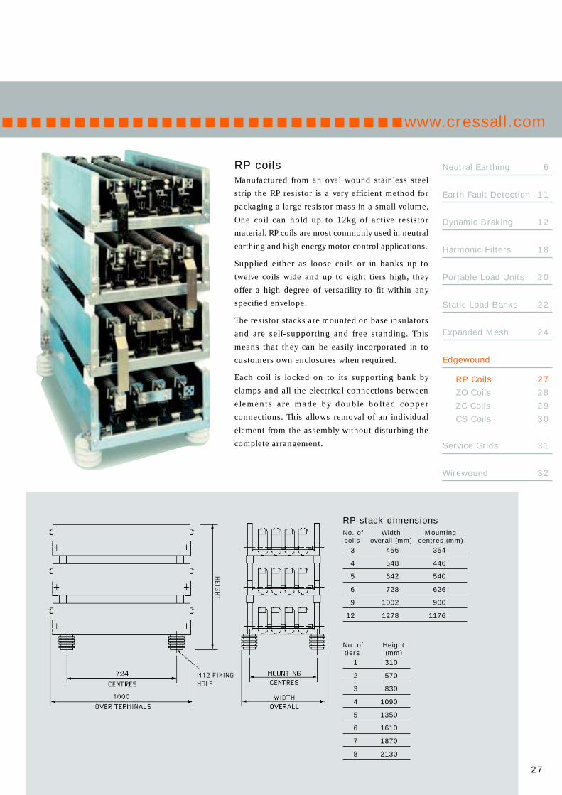
No. of Heighttiers (mm)
1 310
2 570
3 830
4 1090
5 1350
6 1610
7 1870
8 2130
RP coilsManufactured from an oval wound stainless steel
strip the RP resistor is a very efficient method for
packaging a large resistor mass in a small volume.
One coil can hold up to 12kg of active resistor
material. RP coils are most commonly used in neutral
earthing and high energy motor control applications.
Supplied either as loose coils or in banks up to
twelve coils wide and up to eight tiers high, they
offer a high degree of versatility to fit within any
specified envelope.
The resistor stacks are mounted on base insulators
and are self-supporting and free standing. This
means that they can be easily incorporated in to
customers own enclosures when required.
Each coil is locked on to its supporting bank by
clamps and all the electrical connections between
elements are made by double bolted copper
connections. This allows removal of an individual
element from the assembly without disturbing the
complete arrangement.
RP stack dimensionsNo. of Width Mountingcoils overall (mm) centres (mm)
3 456 354
4 548 446
5 642 540
6 728 626
9 1002 900
12 1278 1176
www.cressall.com
Neutral Earthing 6
Earth Fault Detection 11
Dynamic Braking 12
Harmonic Filters 18
Portable Load Units 20
Static Load Banks 22
Expanded Mesh 24
Edgewound
RP Coils 27
ZO Coils 28
ZC Coils 29
CS Coils 30
Service Grids 31
Wirewound 32
28
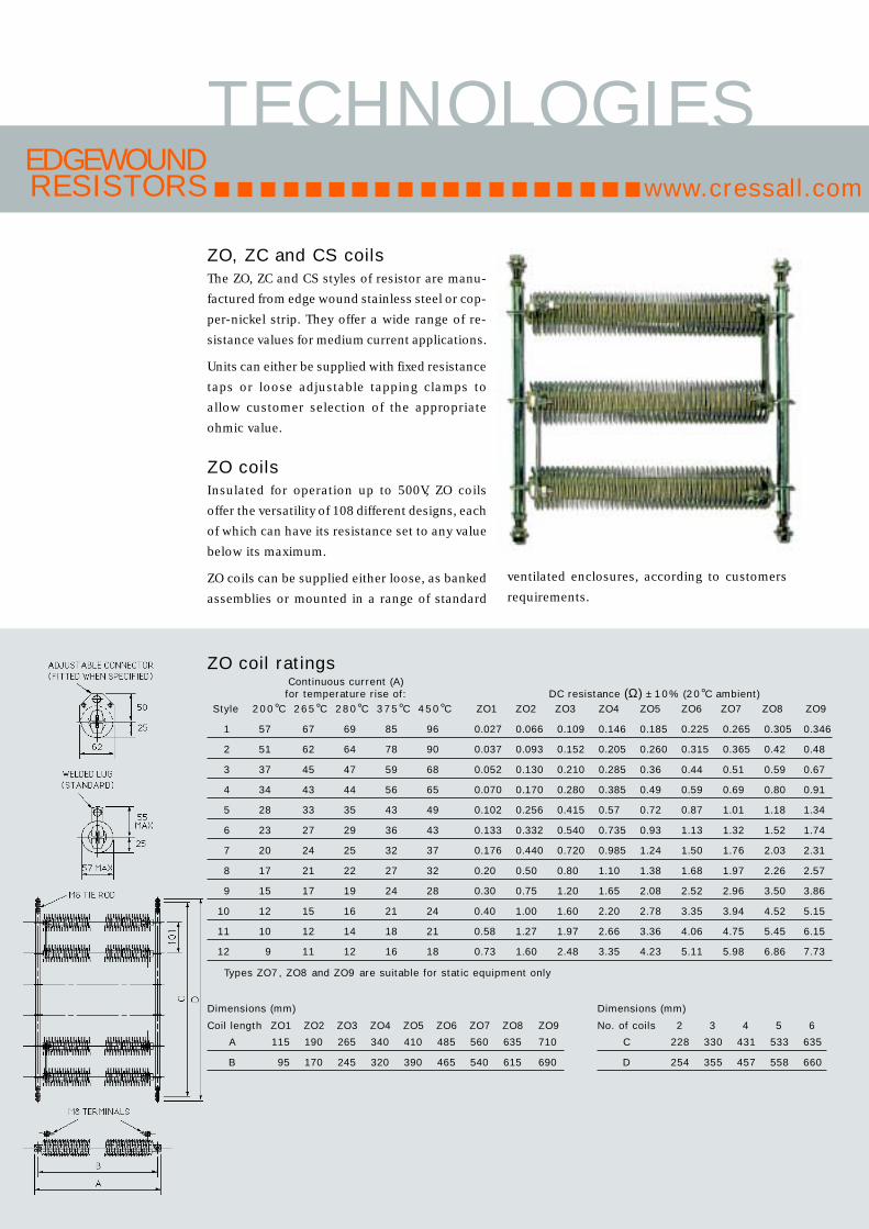
ZO coil ratingsContinuous current (A)for temperature rise of: DC resistance (Ω) ± 10% (20°C ambient)
Style 200°C 265°C 280°C 375°C 450°C ZO1 ZO2 ZO3 ZO4 ZO5 ZO6 ZO7 ZO8 ZO9
1 57 67 69 85 96 0.027 0.066 0.109 0.146 0.185 0.225 0.265 0.305 0.346
2 51 62 64 78 90 0.037 0.093 0.152 0.205 0.260 0.315 0.365 0.42 0.48
3 37 45 47 59 68 0.052 0.130 0.210 0.285 0.36 0.44 0.51 0.59 0.67
4 34 43 44 56 65 0.070 0.170 0.280 0.385 0.49 0.59 0.69 0.80 0.91
5 28 33 35 43 49 0.102 0.256 0.415 0.57 0.72 0.87 1.01 1.18 1.34
6 23 27 29 36 43 0.133 0.332 0.540 0.735 0.93 1.13 1.32 1.52 1.74
7 20 24 25 32 37 0.176 0.440 0.720 0.985 1.24 1.50 1.76 2.03 2.31
8 17 21 22 27 32 0.20 0.50 0.80 1.10 1.38 1.68 1.97 2.26 2.57
9 15 17 19 24 28 0.30 0.75 1.20 1.65 2.08 2.52 2.96 3.50 3.86
10 12 15 16 21 24 0.40 1.00 1.60 2.20 2.78 3.35 3.94 4.52 5.15
11 10 12 14 18 21 0.58 1.27 1.97 2.66 3.36 4.06 4.75 5.45 6.15
12 9 11 12 16 18 0.73 1.60 2.48 3.35 4.23 5.11 5.98 6.86 7.73
Types ZO7, ZO8 and ZO9 are suitable for static equipment only
Dimensions (mm)
Coil length ZO1 ZO2 ZO3 ZO4 ZO5 ZO6 ZO7 ZO8 ZO9
A 115 190 265 340 410 485 560 635 710
B 95 170 245 320 390 465 540 615 690
Dimensions (mm)
No. of coils 2 3 4 5 6
C 228 330 431 533 635
D 254 355 457 558 660
ventilated enclosures, according to customers
requirements.
EDGEWOUNDRESISTORS
ZO, ZC and CS coilsThe ZO, ZC and CS styles of resistor are manu-
factured from edge wound stainless steel or cop-
per-nickel strip. They offer a wide range of re-
sistance values for medium current applications.
Units can either be supplied with fixed resistance
taps or loose adjustable tapping clamps to
allow customer selection of the appropriate
ohmic value.
ZO coilsInsulated for operation up to 500V, ZO coils
offer the versatility of 108 different designs, each
of which can have its resistance set to any value
below its maximum.
ZO coils can be supplied either loose, as banked
assemblies or mounted in a range of standard
TECHNOLOGIESwww.cressall.com

29
MOUNTING CENTRES
B
OVERALL WIDTH
AE
D
C
Dimensions (mm)
4 coils wide 6 coils wide ZC5 ZC7
A B A B D E D E
254 228 350 330 480 500 630 650
No of tiers C1 125
2 250
3 375
ZC coil ratingsContinuous current (A) DC resistance (Ω)for temperature rise of: ± 10% (20°C ambient)
Style 200°C 265°C 280°C 375°C 450°C ZC5 ZC7
1 57 67 69 85 96 0.185 0.265
2 51 62 64 78 90 0.260 0.365
3 37 45 47 59 68 0.36 0.51
4 34 43 44 56 65 0.49 0.69
5 28 33 35 43 49 0.72 1.01
6 23 27 29 36 43 0.93 1.32
7 20 24 25 32 37 1.24 1.76
8 17 21 22 27 32 1.38 1.97
9 15 17 19 24 28 2.08 2.96
10 12 15 16 21 24 2.78 3.94
11 10 12 14 18 21 3.36 4.75
12 9 11 12 16 18 4.23 5.98
www.cressall.com
Neutral Earthing 6
Earth Fault Detection 11
Dynamic Braking 12
Harmonic Filters 18
Portable Load Units 20
Static Load Banks 22
Expanded Mesh 24
Edgewound
RP Coils 27
ZO Coils 28
ZC Coils 29
CS Coils 30
Service Grids 31
Wirewound 32
ZC coilsDesigned for dynamic braking resistors ZC
elements are similar in construction to the well
established ZO range.
Supported on M8 threaded rod, ZC ’s are
available in two lengths, they are insulated for
operation at up to 800V and can be supplied
loose, mounted between end plates or housed
in one of our standard range of enclosures.

30
EDGEWOUNDRESISTORS
CS coil ratingsContinuous current (A) DC resistance (Ω) ± 10%for temperature rise of: (20°C ambient)
Style 200°C 265°C 280°C 375°C 450°C CS9 CS12 CS15
1 57 67 69 85 96 0.129 0.172 0.212
2 51 62 64 78 90 0.182 0.242 0.296
3 37 45 47 59 68 0.252 0.355 0.415
4 34 43 44 56 65 0.341 0.455 0.555
5 28 33 35 43 49 0.505 0.670 0.820
6 23 27 29 36 43 0.650 0.865 1.060
7 20 24 25 32 37 0.87 1.15 1.41
8 17 21 22 27 32 0.98 1.28 1.58
9 15 17 19 24 28 1.46 1.94 2.36
10 12 15 16 21 24 1.95 2.58 3.15
11 10 12 14 18 21 2.26 3.02 3.74
12 9 11 12 16 18 2.84 3.79 4.68
No. ofelements A B
2 250 200
3 330 280
4 410 360
5 490 440
6 570 520
7 650 600
8 730 680
9 810 760
10 890 840
Additional dimensions (mm) for type CSC: 25mm min.D: 25mm min.E: CS9 - 295mm. CS12 - 370mm. CS15 - 445mm.F: CS9 - 335mm. CS12 - 410mm. CS15 - 485mm.For 1.5kV primary insulation add 25mm to A & B dimensions.For 3.3kV primary insulation add 75mm to A & B dimensions
TECHNOLOGIES
CS coilsDeveloped for use in bank form the CS
coil is as standard insulated for operation
at 750V, the design is such that this can
be increased to 1.5kV or 3.3kV if required.
www.cressall.com

31
Service grids
• Modular
• Shock and vibration resistant
• Range of standard enclosures
• Specifically designed for motorcontrol
Service grids are a robust flat plate style of
resistor manufactured from 304 grade stainless
steel elements insulated using mica and welded
together to form a continuous low inductance
resistance path. Service grid resistors can be
supplied as either open banks or housed in
ventilated enclosures.
Every grid has punched holes within the welded
contact section to give intermediate tapping
points.
EnclosuresThere are two standard enclosure styles for
service grid resistors; Industrial Housings for
general purpose applications and System 22
Housings designed for steel mills, this allows the
replacement of individual banks without disturb-
ing other banks in the enclosure.
Either type of enclosure can be supplied as
painted mild steel, hot dip galvanized to BS729
or natural finish grade 304 stainless steel.
SERVICEGRIDSwww.cressall.com
Neutral Earthing 6
Earth Fault Detection 11
Dynamic Braking 12
Harmonic Filters 18
Portable Load Units 20
Static Load Banks 22
Expanded Mesh 24
Edgewound
RP Coils 27
ZO Coils 28
ZC Coils 29
CS Coils 30
Service Grids
Wirewound 32

32
GP resistor dataDC Ω DC Ω Current ratings for 300°C
GP6/9 ± 10% GP12 ± 10% temperature rise (A)style @20°C style @20°C Contin- Short time rating (secs)no. GP6 GP9 no. GP12 uous 5 10 30
1 0.13 0.28 1 0.41 30 152 139 114
2 0.16 0.36 2 0.52 27 137 125 103
3 0.21 0.46 3 0.68 24 120 109 90
4 0.23 0.52 4 0.75 23 114 104 86
5 0.29 0.65 5 0.94 20 102 93 77
6 0.38 0.84 6 1.23 18 89 81 67
7 0.52 1.10 7 1.66 15 76 69 57
8 0.65 1.40 8 2.1 14 68 62 51
9 0.83 1.80 9 2.7 12 60 55 45
10 0.94 2.0 10 3.0 11 56 52 43
11 1.17 2.6 11 3.8 10 51 46 38
12 1.50 3.3 12 4.9 9 45 41 34
13 2.0 4.3 13 6.4 7.7 39 35 29
14 2.3 5.1 14 7.6 7.2 36 33 27
15 2.8 6.1 15 9.1 6.5 33 29 25
16 3.6 7.8 16 11.5 5.8 29 26 22
17 4.2 9.3 17 13.7 5.3 27 24 20
18 5.1 11.2 18 16.5 5.1 24 22 18
- - - - - - - - -
21 5.7 12.4 24 18.4 4.9 22 20 15
22 7.5 16.4 25 24.3 4.5 19 17 13
23 10.3 22.4 26 33 3.8 16 15 11
24 14.6 32 27 47 3.2 14 12 9.44
25 21.7 47 28 69 2.6 11 10 7.74
26 27 59 29 87 2.3 10 9.03 6.94
27 34 75 30 110 2.1 9.08 8.04 6.18
28 44 96 31 143 1.8 7.98 7.07 5.44
29 59 128 32 190 1.6 6.89 6.11 4.69
30 80 175 33 260 1.4 5.92 5.24 4.03
31 105 230 34 340 1.2 5.16 4.58 3.52
32 143 310 35 460 1.0 4.42 3.92 3.02
33 183 400 36 590 0.90 3.91 3.47 2.67
34 240 520 37 780 0.80 3.42 3.03 2.33
35 290 640 38 950 0.72 3.11 2.75 2.12
36 360 790 39 1170 0.65 2.79 2.47 1.90
37 450 990 40 1470 0.58 2.49 2.21 1.70
38 580 1260 41 1870 0.51 2.20 1.95 1.50
39 670 1460 42 2170 0.47 2.04 1.81 1.39
40 830 1800 43 2670 0.42 1.84 1.63 1.25
41 1030 2260 44 3360 0.38 1.65 1.46 1.12
42 1320 2880 45 4280 0.33 1.46 1.29 0.99
43 1740 - - - 0.29 1.27 1.12 0.86
44 2330 - - - 0.25 1.0 0.97 0.75
45 3130 - - - 0.21 0.95 0.84 0.64
46 4650 - - - 0.18 0.78 0.69 0.53
47 7500 - - - 0.14 0.61 0.54 0.42
WIREWOUNDRESISTORS
Coiled wire resistorsA compact and economical solution for high
resistance and low power applications. Elements
are manufactured using nickel-chrome or
copper-nickel wound onto ceramic formers.
Elements can be supplied either loose, as banked
assemblies or mounted in a range of standard
ventilated enclosures, according to customers
requirements.
TECHNOLOGIESwww.cressall.com

33
GP resistor sizes (mm)Unit A B C D E
GP6 194 159 181 37 53
GP9 257 222 244 54 68
GP12 356 311 343 54 68
GP coilsA well proven range of 125 units allows easy selec-
tion of the most appropriate resistor for the duty.
The coils are manufactured using nickel-chrome
or copper-nickel alloys wound onto a solid
ceramic former.
Each coil is supported on a flat steel bar which
passes through the centre of the former and is
secured by spring clips.
www.cressall.com
Adjustable tappings can be provided by adding
one or more tapping bands.
Two types are available, standard and heavy duty,
rated for continuous currents of up to 20A and
60A respectively.
Each tapping band shorts out the resistance wire
it covers; the consequent reduction in value of
the overall resistance of the unit is in the range
of 1% to 4%, double for heavy duty tapping bands.
GP stack dimensionsNo. of Width Mounting No. of Height coils overall (mm) centres (mm) tiers (mm)
1 266 164 1 200
2 344 242 2 351
3 423 321 3 502
4 501 399 4 653
5 580 478 5 804
6 658 556 6 955
7 737 635 7 1106
8 815 713 8 1257
9 894 792 9 1408
10 972 870 10 1559
Neutral Earthing 6
Earth Fault Detection 11
Dynamic Braking 12
Harmonic Filters 18
Portable Load Units 20
Static Load Banks 22
Expanded Mesh 24
Edgewound 26
Service Grids 31
Wirewound
GP Coils 33
CC Coils 34

34
CC coil ratingMaximum Continuous
Coil resistance (Ω)± 10% current, (A) fortype (@20°C ambient) 600°C temp rise
CC8 5.0 10.00
CC9 8.0 7.90
CC10 10.0 7.07
CC11 17.0 5.42
CC12 25.0 4.47
CC13 35.0 3.78
CC14 55.0 3.00
CC15 70.0 2.67
CC16 100.0 2.24
CC17 130.0 1.96
CC coilsThe CC coiled coil resistor was developed mainly
for use in dynamic braking. Its open wound coil
arrangement allows operation at up to ten times
its normal power rating for short periods while
retaining quick cooling times.
The CC coil is manufactured from a coil of nickel-
chrome or copper-nickel alloy wound around a
ceramic former, supported on M8 threaded rod.
Up to three coils can be supported on one rod
allowing easy series and parallel connection and
installation.
WIREWOUNDRESISTORS
TECHNOLOGIESwww.cressall.com
Dimensions (mm)
3 wide 4 wide No ofB D B D tiers H
1 coil long 260 200 260 250 1 150
2 coils long 440 200 440 250 2 300
3 coils long 630 200 630 250 3 450

35
www.cressall.com
For information on transit
and traction applications contact:
Cressall Resistors Transit
Peacock Way
Melton Constable
Norfolk NR24 2BZ
United Kingdom
Tel: +44 (0) 1263 860581
Fax: +44 (0) 1263 861417
email: [email protected]
Neutral Earthing 6
Earth Fault Detection 11
Dynamic Braking 12
Harmonic Filters 18
Portable Load Units 20
Static Load Banks 22
Expanded Mesh 24
Edgewound 26
Service Grids 31
Wirewound
GP Coils 33
CC Coils 34
REPLACEMENT RESISTORSCressall have been producing quality resistors for over 100 years. Our
resistors have the reputation for both reliability and longevity. Over the
years we have acquired other resistor companies and have successfully
integrated their technology into our range. In many cases this means we
have a library of technical and contract data to which we can refer.
We hold information on resistors previously supplied under the
following names:
• GEC Alsthom
• GEC Industrial Controls
• Eaton Cutler Hammer
• British Thompson Houston (BTH)
• AEI
• Fawcett Preston
• H. A. Birch
• Expamet
• E. A. Walshe
• BHI
We can also supply resistors that can be used to replace our
competitors’ products, this we can do providing we know the rating or
the duty of the resistor involved.
Issu
e 2
© 2
00
2 C
ress
all R
esis
tors
Ltd
Your Local Distributor:Cressall Resistors LtdEvington Valley RoadLeicester LE5 5LZUnited KingdomTel: +44 (0) 116 273 3633Fax: +44 (0) 116 273 7911email: [email protected]
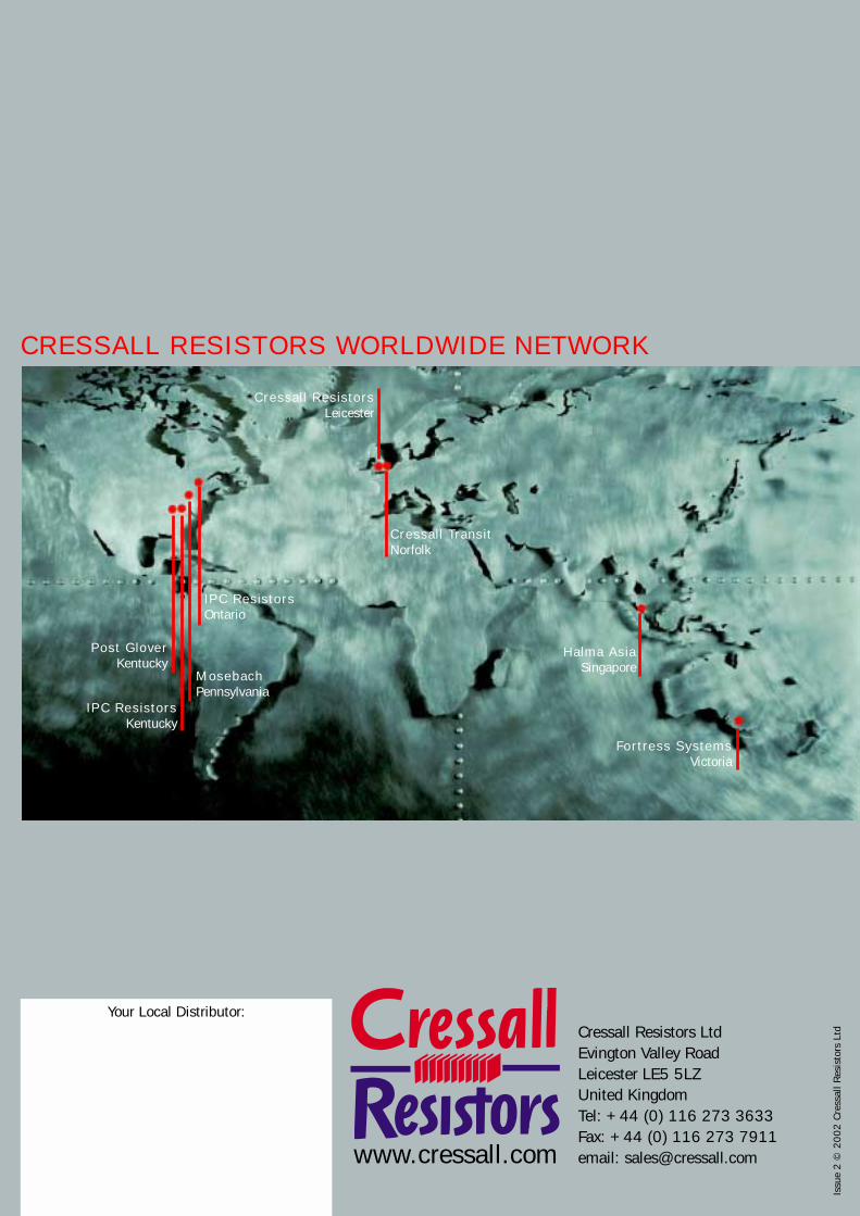
CRESSALL RESISTORS WORLDWIDE NETWORK
Post GloverKentucky
IPC ResistorsKentucky
MosebachPennsylvania
IPC ResistorsOntario
Cressall ResistorsLeicester
Cressall TransitNorfolk
Halma AsiaSingapore
Fortress SystemsVictoria