impact of data modeling and database implementation …
TRANSCRIPT
IMPACT OF DATA MODELING AND DATABASE IMPLEMENTATION
METHODS ON THE OPTIMIZATION OF CONCEPTUAL AIRCRAFT DESIGN
A Thesis
Presented to
The Academic Faculty
by
Neil Scott Hall
In Partial Fulfillment
of the Requirements for the Degree
Master of Science in Mechanical Engineering
Georgia Institute of Technology
June 1996
ii
IMPACT OF DATA MODELING AND DATABASE IMPLEMENTATION
METHODS ON THE OPTIMIZATION OF CONCEPTUAL AIRCRAFT DESIGN
Approved:
__________________________
Dr. Robert E. Fulton, Chairman
Professor Mechanical Engineering
__________________________
Dr. Suresh K. Sitaraman
Assistant Professor Mechanical Engineering
__________________________
Dr. James I. Craig
Professor Aerospace Engineering
Date Approved _____________

iii
ACKNOWLEDGMENT
The author would like to express his sincere appreciation to Dr. Robert E. Fulton for
providing me with the unique opportunity to conduct research in the area of information
management while supporting a family. His encouragement and confidence will always
be valued.
I would like to thank James J. Duhig, Jr. of the Atlanta Electronic Commerce
Resource Center. Jim’s wealth of industry experience provided me with immeasurable
insight into the practical implications of information management.
The author would like to express his appreciation to Johnny Stamper, Aaron Harcrow,
Paul Cole, Bill Hood, and Charlie Novak of Lockheed Aeronautical Systems Company
for their creative and technical input.
And lastly, the author would like to thank Gintas Jazbutis and M. C. Ramesh for
answering any question that I could come up with, and a special thanks to Diego
Tamburini for his assistance with STEP tools.
iv
TABLE OF CONTENTS
ACKNOWLEDGMENT . . . . . . . . . . . . . . . . . . . . . . . . . . . . . . . . . . . . . . . . . iii
LIST OF TABLES . . . . . . . . . . . . . . . . . . . . . . . . . . . . . . . . . . . . . . . . . . . . . . vii
LIST OF FIGURES . . . . . . . . . . . . . . . . . . . . . . . . . . . . . . . . . . . . . . . . . . . . . viii
SYMBOLS AND NOMENCLATURE . . . . . . . . . . . . . . . . . . . . . . . . . . . . . . xi
SUMMARY . . . . . . . . . . . . . . . . . . . . . . . . . . . . . . . . . . . . . . . . . . . . . . . . . . . . xiii
I THE CONCEPTUAL AIRCRAFT DESIGN PROCESS AND
ITS DATA MANAGEMENT . . . . . . . . . . . . . . . . . . . . . . .. . . . . . . . . . . 1
1 Introduction . . . . . . . . . . . . . . . . . . . . . . . . . . . . . . . . . . . . . . . . . . . . . 1
2 The Design Process . . . . . . . . . . . . . . . . . . . . . . . . . . . . . . . . . . . . . . . 2
3 Data Management as a Discipline . . . . . . . . . . . . . . . . . . . . . . . . . . . . 4
4 Data Flow . . . . . . . . . . . . . . . . . . . . . . . . . . . . . . . . . . . . . . . . . . . . . . 5
5 Geometric Data . . . . . . . . . . . . . . . . . . . . . . . . . . . . . . . . . . . . . . . . . . 7
6 Product Data Models . . . . . . . . . . . . . . . . . . . . . . . . . . . . . . . . . . . . . . 8
6.1 PDES . . . . . . . . . . . . . . . . . . . . . . . . . . . . . . . . . . . . . . . . . . . . . . . 9
II PROCESS MODELING . . . . . . . . . . . . . . . . . . . . . . . . . . . . . . . . . . . . . 11
1 Surface Models . . . . . . . . . . . . . . . . . . . . . . . . . . . . . . . . . . . . . . . . . . 11
v
2 IDEF0 Model . . . . . . . . . . . . . . . . . . . . . . . . . . . . . . . . . . . . . . . . . . . 13
III RELATIONAL DATABASE DESIGN APPROACH . . . . . . . . . . . . . 21
1 Data Relationships Modeling . . . . . . . . . . . . . . . . . . . . . . . . . . . . . . . 21
1.1 Database Schema . . . . . . . . . . . . . . . . . . . . . . . . . . . . . . . . . . . . . 22
1.2 Data Dictionary . . . . . . . . . . . . . . . . . . . . . . . . . . . . . . . . . . . . . . 22
1.3 Normal Forms in Relational Design . . . . . . . . . . . . . . . . . . . . . . .23
1.4 Logical Database Design ( IDEF1X ) . . . . . . . . . . . . . . . . . . . . . 25
1.5 Implementation of Database Design . . . . . . . . . . . . . . . . . . . . . . 34
IV OBJECT-ORIENTED DATABASE DESIGN APPROACH . . . . . . . 35
1 Data Relationships Modeling . . . . . . . . . . . . . . . . . . . . . . . . . . . . . . . 35
1.1 Database Schema . . . . . . . . . . . . . . . . . . . . . . . . . . . . . . . . . . . . . 35
1.2 Data Dictionary . . . . . . . . . . . . . . . . . . . . . . . . . . . . . . . . . . . . . . .36
1.3 Logical Database Design ( EXPRESS ) . . . . . . . . . . . . . . . . . . . . 36
1.4 Implementation of Database Design . . . . . . . . . . . . . . . . . . . . . . 50
V DATABASE PERFORMANCE METRICS . . . . . . . . . . . . . . . . . . . . . 51
1 Benchmarks . . . . . . . . . . . . . . . . . . . . . . . . . . . . . . . . . . . . . . . . . . . . . 51
2 Performance Comparisons of ORACLE and ROSE/C++
Database Models . . . . . . . . . . . . . . . . . . . . . . . . . . . . . . . . . . . . . . . . .53
VI DESIGN COMPARISONS . . . . . . . . . . . . . . . . . . . . . . . . . . . . . . . . . . 57
1 Evaluation of IDEF1X and EXPRESS ( General ) . . . . . . . . . . . . . . . 57
vi
2 Evaluation of IDEF1X and EXPRESS ( Specific ) . . . . . . . . . . . . . . . 57
VII CONCLUSIONS . . . . . . . . . . . . . . . . . . . . . . . . . . . . . . . . . . . . . . . . . . . .61
VIII RECOMMENDATIONS . . . . . . . . . . . . . . . . . . . . . . . . . . . . . . . . . . . . . 66
A DATA SCHEMA . . . . . .. . . . . . . . . . . . . . . . . . . . . . . . . . . . . . . . . . . . . .70
B DATA DICTIONARY . . . . . . . . . .. . . . . . . . . . . . . . . . . . . . . . . . . . . . . .74
C LEXICAL EXPRESS MODEL . . . . . . . . . . . . . . . . . . . . . . . . . . . . . . . .93
D EXPRESS MODEL DATA TYPES . . . . . .. . . . . . . . . . . . . . . . . . . . . . 113
REFERENCES . . . . . . . . . . . . . . . . . . . . . . . . . . . . . . . . . . . . . . . . . . . . . . . . .117
vii
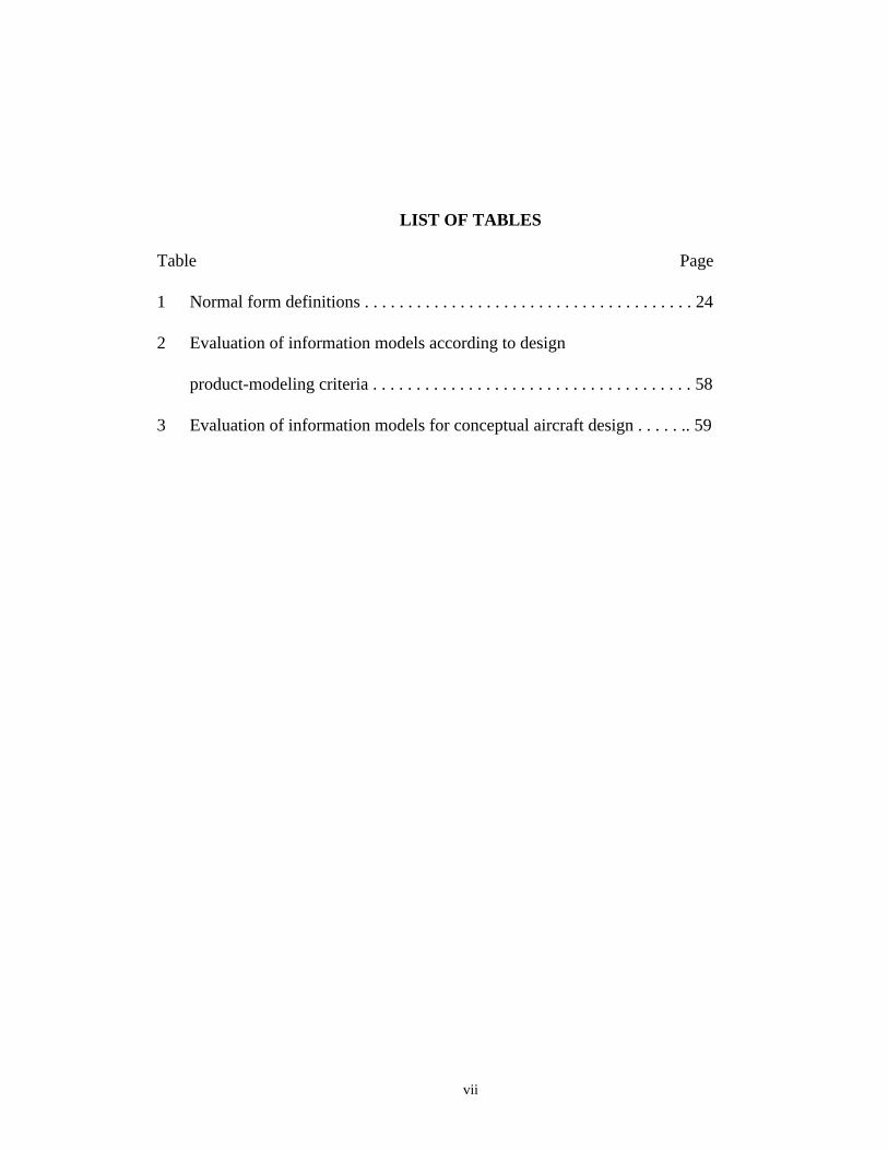
LIST OF TABLES
Table Page
1 Normal form definitions . . . . . . . . . . . . . . . . . . . . . . . . . . . . . . . . . . . . . . 24
2 Evaluation of information models according to design
product-modeling criteria . . . . . . . . . . . . . . . . . . . . . . . . . . . . . . . . . . . . . 58
3 Evaluation of information models for conceptual aircraft design . . . . . .. 59
viii
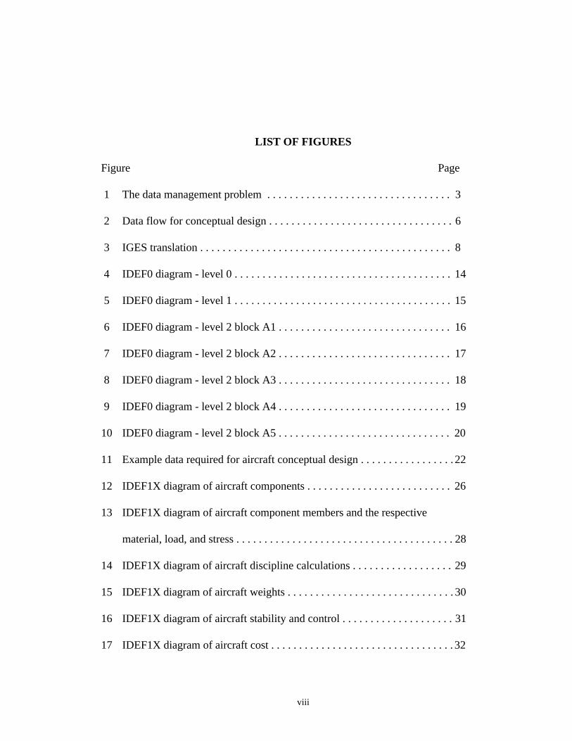
LIST OF FIGURES
Figure Page
1 The data management problem . . . . . . . . . . . . . . . . . . . . . . . . . . . . . . . . . 3
2 Data flow for conceptual design . . . . . . . . . . . . . . . . . . . . . . . . . . . . . . . . . 6
3 IGES translation . . . . . . . . . . . . . . . . . . . . . . . . . . . . . . . . . . . . . . . . . . . . . 8
4 IDEF0 diagram - level 0 . . . . . . . . . . . . . . . . . . . . . . . . . . . . . . . . . . . . . . . 14
5 IDEF0 diagram - level 1 . . . . . . . . . . . . . . . . . . . . . . . . . . . . . . . . . . . . . . . 15
6 IDEF0 diagram - level 2 block A1 . . . . . . . . . . . . . . . . . . . . . . . . . . . . . . . 16
7 IDEF0 diagram - level 2 block A2 . . . . . . . . . . . . . . . . . . . . . . . . . . . . . . . 17
8 IDEF0 diagram - level 2 block A3 . . . . . . . . . . . . . . . . . . . . . . . . . . . . . . . 18
9 IDEF0 diagram - level 2 block A4 . . . . . . . . . . . . . . . . . . . . . . . . . . . . . . . 19
10 IDEF0 diagram - level 2 block A5 . . . . . . . . . . . . . . . . . . . . . . . . . . . . . . . 20
11 Example data required for aircraft conceptual design . . . . . . . . . . . . . . . . . 22
12 IDEF1X diagram of aircraft components . . . . . . . . . . . . . . . . . . . . . . . . . . 26
13 IDEF1X diagram of aircraft component members and the respective
material, load, and stress . . . . . . . . . . . . . . . . . . . . . . . . . . . . . . . . . . . . . . . 28
14 IDEF1X diagram of aircraft discipline calculations . . . . . . . . . . . . . . . . . . 29
15 IDEF1X diagram of aircraft weights . . . . . . . . . . . . . . . . . . . . . . . . . . . . . . 30
16 IDEF1X diagram of aircraft stability and control . . . . . . . . . . . . . . . . . . . . 31
17 IDEF1X diagram of aircraft cost . . . . . . . . . . . . . . . . . . . . . . . . . . . . . . . . . 32
ix
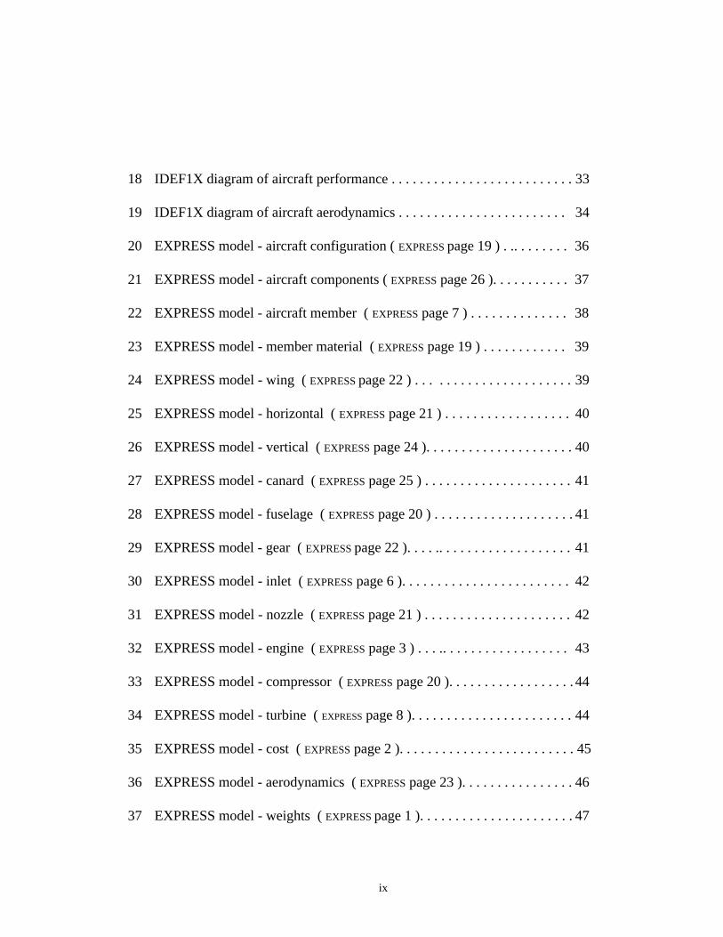
18 IDEF1X diagram of aircraft performance . . . . . . . . . . . . . . . . . . . . . . . . . . 33
19 IDEF1X diagram of aircraft aerodynamics . . . . . . . . . . . . . . . . . . . . . . . . 34
20 EXPRESS model - aircraft configuration ( EXPRESS page 19 ) . .. . . . . . . . 36
21 EXPRESS model - aircraft components ( EXPRESS page 26 ). . . . . . . . . . . 37
22 EXPRESS model - aircraft member ( EXPRESS page 7 ) . . . . . . . . . . . . . . 38
23 EXPRESS model - member material ( EXPRESS page 19 ) . . . . . . . . . . . . 39
24 EXPRESS model - wing ( EXPRESS page 22 ) . . . . . . . . . . . . . . . . . . . . . . 39
25 EXPRESS model - horizontal ( EXPRESS page 21 ) . . . . . . . . . . . . . . . . . . 40
26 EXPRESS model - vertical ( EXPRESS page 24 ). . . . . . . . . . . . . . . . . . . . . 40
27 EXPRESS model - canard ( EXPRESS page 25 ) . . . . . . . . . . . . . . . . . . . . . 41
28 EXPRESS model - fuselage ( EXPRESS page 20 ) . . . . . . . . . . . . . . . . . . . . 41
29 EXPRESS model - gear ( EXPRESS page 22 ). . . . .. . . . . . . . . . . . . . . . . . . 41
30 EXPRESS model - inlet ( EXPRESS page 6 ). . . . . . . . . . . . . . . . . . . . . . . . 42
31 EXPRESS model - nozzle ( EXPRESS page 21 ) . . . . . . . . . . . . . . . . . . . . . 42
32 EXPRESS model - engine ( EXPRESS page 3 ) . . . .. . . . . . . . . . . . . . . . . . 43
33 EXPRESS model - compressor ( EXPRESS page 20 ). . . . . . . . . . . . . . . . . . 44
34 EXPRESS model - turbine ( EXPRESS page 8 ). . . . . . . . . . . . . . . . . . . . . . . 44
35 EXPRESS model - cost ( EXPRESS page 2 ). . . . . . . . . . . . . . . . . . . . . . . . . 45
36 EXPRESS model - aerodynamics ( EXPRESS page 23 ). . . . . . . . . . . . . . . . 46
37 EXPRESS model - weights ( EXPRESS page 1 ). . . . . . . . . . . . . . . . . . . . . . 47

x
38 EXPRESS model - performance ( EXPRESS page 5 ). . . . . . .. . . . . . . . . . . 48
39 EXPRESS model - stability and control ( EXPRESS page 4 ). . . . . . . . . . . 49
40 OO1 benchmark comparison of traditional relational DBMS against
object-oriented database programming language in seconds . . . . . . . . . . . 52
41 Relational schema for the stability and control data . . . . . . . . . . . . . . . . . 55
42 Object-oriented schema for the stability and control data . . . . . . . . . . . . . .55
43 Comparison of ORACLE against object-oriented database
programming language (C++) for table lookups in seconds . . . . . . . . . . . . 56
44 Relational database representation of a wing surface . . . . . . . . . . . . . . . . 64
45 Recommended database design strategy and standards . . . . . . . . . . . . . . . . 69
46 EXPRESS model data types . . . . . . . . . . . . . . . . . . . . . . . . . . . . . . . . . . . . 113
xi
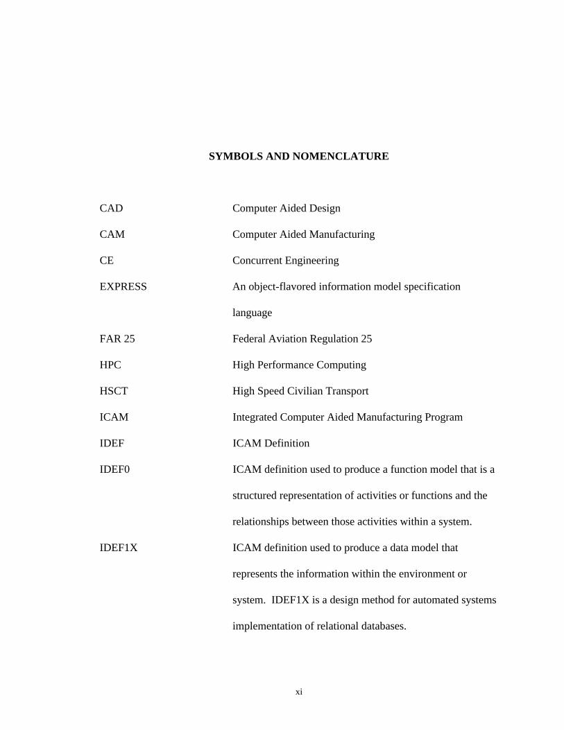
SYMBOLS AND NOMENCLATURE
CAD Computer Aided Design
CAM Computer Aided Manufacturing
CE Concurrent Engineering
EXPRESS An object-flavored information model specification
language
FAR 25 Federal Aviation Regulation 25
HPC High Performance Computing
HSCT High Speed Civilian Transport
ICAM Integrated Computer Aided Manufacturing Program
IDEF ICAM Definition
IDEF0 ICAM definition used to produce a function model that is a
structured representation of activities or functions and the
relationships between those activities within a system.
IDEF1X ICAM definition used to produce a data model that
represents the information within the environment or
system. IDEF1X is a design method for automated systems
implementation of relational databases.
xii
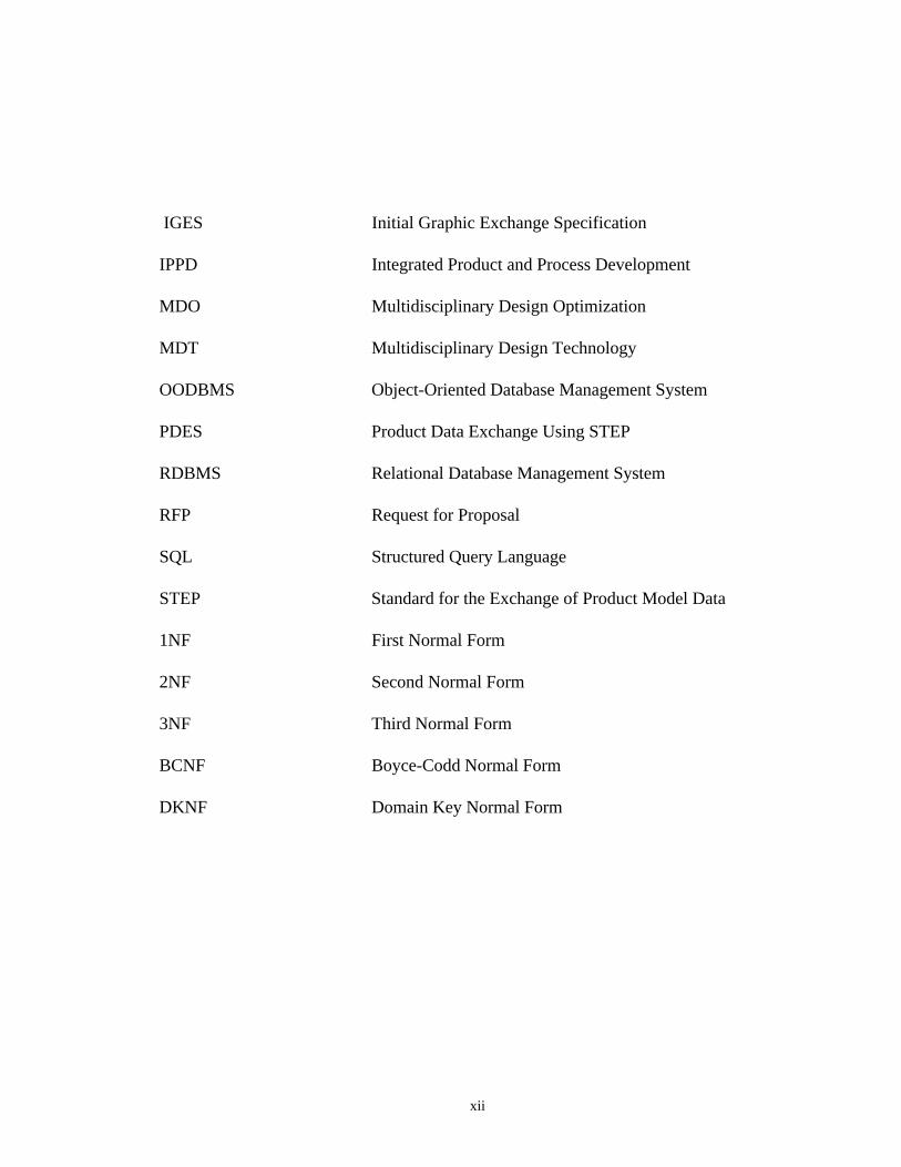
IGES Initial Graphic Exchange Specification
IPPD Integrated Product and Process Development
MDO Multidisciplinary Design Optimization
MDT Multidisciplinary Design Technology
OODBMS Object-Oriented Database Management System
PDES Product Data Exchange Using STEP
RDBMS Relational Database Management System
RFP Request for Proposal
SQL Structured Query Language
STEP Standard for the Exchange of Product Model Data
1NF First Normal Form
2NF Second Normal Form
3NF Third Normal Form
BCNF Boyce-Codd Normal Form
DKNF Domain Key Normal Form
xiii
SUMMARY
Advances in the aircraft technologies have resulted in an increase in the amount of data
required to define a design during the conceptual stages. A conceptual design dictates a
close multidisciplinary effort requiring large amounts of data exchange. In order to
optimize the design process, it is crucial that a top-down data management design
structure be in place in the early phases of the design. This structure will provide
consistency in data format and allow ease of data exchange between the various
disciplines involved in the design process. In the conceptual design phase,
consideration must be given to the changing structure of the of the database as the product
design evolves. Current database design approaches are typically limited to the detailed
design phase where the data organization is fixed.
The goal of the research was to develop a database design approach to support the
conceptual design of complex engineering products where the database organization is
evolving. The research investigates the relative merits of a relational and object-oriented
approach to database design for a multidisciplinary aircraft design effort. The target
application will be the conceptual design of the HSCT wing. On a conceptual level,
complete database design methodologies have been developed that include all
disciplinary data required in the conceptual design phase. The relational and object-
xiv
oriented design methodologies were applied directly to the stability and control section of
the design. This research documents these proposed approaches and recommends
possible database design strategies.
1
CHAPTER I
THE CONCEPTUAL AIRCRAFT DESIGN PROCESS AND DATAMANAGEMENT
Introduction
New aerospace designs will incorporate new concepts as a result of advances made in
the scientific and engineering technologies. These new concepts will afford the aircraft
designer with an interesting and somewhat envious dilemma. The aircraft designer will
have unprecedented flexibility in design concepts. However, this new flexibility will
often be paralleled in ever increasing design complexity. Aircraft such as the High Speed
Civil Transport (HSCT) will provide a design environment which will require the
efficient use of new technologies in an arena which has historically proven to have
stringent performance and cost goals which must be met in order to result in a successful
design. The complexity of the HSCT design will dictate a close multidisciplinary effort
requiring large amounts of data exchange. Moreover, with the enormous development
costs associated with such a design, corporate teaming is essential. It is critical to the
success of the HSCT and future aircraft design that a new approach be taken toward the
management and exchange of information. A top-down data management design
structure should be developed and implemented in the early stages in order to optimize
the design process.
2
The Design Process
It is common in the design process for the aircraft designer/configurator to begin with
a set of aircraft specifications defined by the customer. A study is made of various
configurations which have the qualities which satisfy these specifications. As the
designer/configurator nears completion of the design iteration, the design is chosen which
first satisfies the major constraints which define the aircraft geometry such as overall span
for airport gate access, cruising speed, passenger load, cargo capacity, etc.. Reliance
must then be placed on the expertise of other disciplines in order to determine whether or
not the configuration meets performance and cost goals. The exchange of data in this
stage of the design could often be characterized as a "specific need" exchange. In order to
calculate aircraft lift and drag, the aerodynamicist might request planform and cross-
sectional geometric data. However, the structural engineer might want geometric data
that defines crucial stress and load points such as the geometry that defines door and
landing gear locations. The terminology of "specific need" is chosen because the
designer/configurator typically provides each discipline with only that data which is
required in performing the specific task of that discipline. A very common problem
with this method of data exchange is data consistency. It is not uncommon to find that
during the conceptual design phase a particular discipline's updated calculations have not
been effectively communicated with other disciplines involved in the design effort. This
breakdown in the data exchange process results in inconsistent predictions among the
various disciplines and valuable design time is lost in the process of redefining a common
3
basis for evaluation. Other problems with this approach are redundancy and the lack of a
standard data format. It is quite common to find that the data exchanged between
disciplines and supplied by the designer/configurator are often duplicated in a slightly
different format for the various discipline's use. Moreover, each discipline is typically
concerned with “its data requirements” only, and not much thought or concern is given as
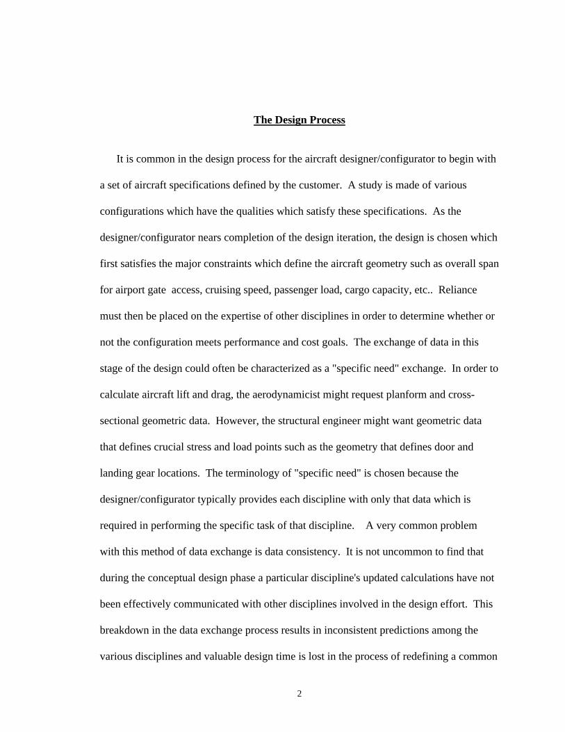
to how the data will be used by another discipline. Figure 1 shows the data management
problem that currently exists in aircraft conceptual design. The figure is somewhat
comical in the way in which it portrays each discipline involved in the conceptual design
process. However, this representation is not far from reality.
Balsa Wood
Micro Film
Weights
Stabilit y and Control
Loads and Stress
Aerod ynamics
Propulsion Reliabilit y, Maintainabilit y
The engine deckis in file “.........”
Cl = 1.2Cd = .0003Cm = -.02
Cl = 1.2Cd = .0003Cm = -.02
Figure 1. The data management problem.

4
Due to the complexity in design and the use of advanced technologies, the HSCT will
require a multidisciplinary effort. Multidisciplinary Design Optimization (MDO), or
Multidisciplinary Design Technology (MDT), will take advantage of the evolving High
Performance Computing (HPC) environment and will be a critical component in the
design of the HSCT. The concept of Integrated Product and Process Development
(IPPD)/Concurrent Engineering (CE) as a means of improving the product development
process is now becoming more critical. In order to ensure design success, it is crucial that
a top-down data management design structure be in place in the early phases of the
design. This structure will provide consistency in data format and allow ease of data
exchange between the various disciplines involved in the design process.
Database Management as a Discipline
Advances in the aircraft technologies have resulted in an increase in the amount of
data required to define a design during the conceptual stages. A conceptual design team
today often includes disciplines which did not exist in earlier times. Aircraft systems
have become more sophisticated and complex and now are critical in the early phases of
the aircraft design process. Although the database management technologies have been
rapidly evolving in recent years, implementation into the aircraft design process has not
proceeded with the same speed. This apparent lack of enthusiasm in introducing data
management as a technology into the conceptual design process can be explain in some

5
part due to the level of maturity with which database technology has advanced. Another
reason is that the design processes developed by the various aircraft manufacturers have
evolved over many years and are the result of these many years of experience.
Another issue is cost. The cost of introducing a new technology into a tried and
proven process is time consuming and often expensive. The arguments against the
introduction of a new method into the design process serves somewhat as a check and
balance. However, with the enormous amounts of money spent and effort that will be
expended on the design of future aircraft, more efficient methods must be in place. The
design of the HSCT provides an unique opportunity for the introduction of a data
management structure. The HSCT is unlike any aircraft previously built. The
performance requirements for the HSCT make it an unique design challenge where no
design precedent exists. The complexity in design, the new technologies required, and
the need for high speed computing early on make the HSCT an excellent candidate for the
implementation of new database technologies.
Data Flow
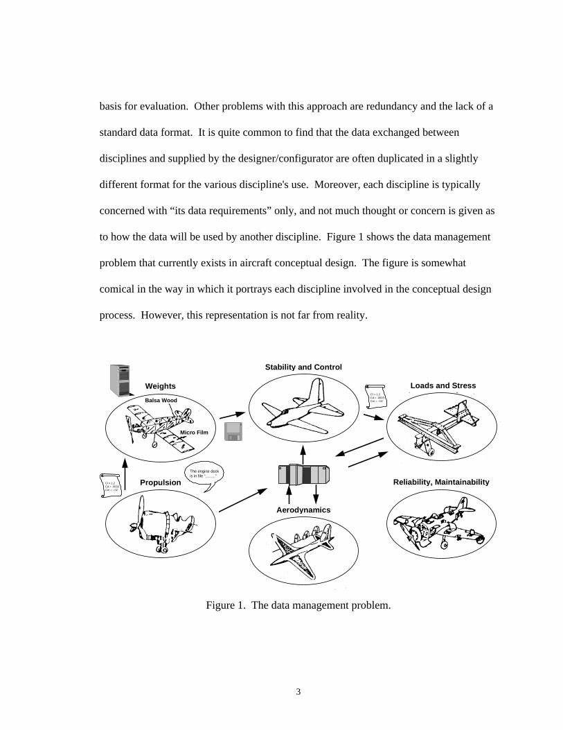
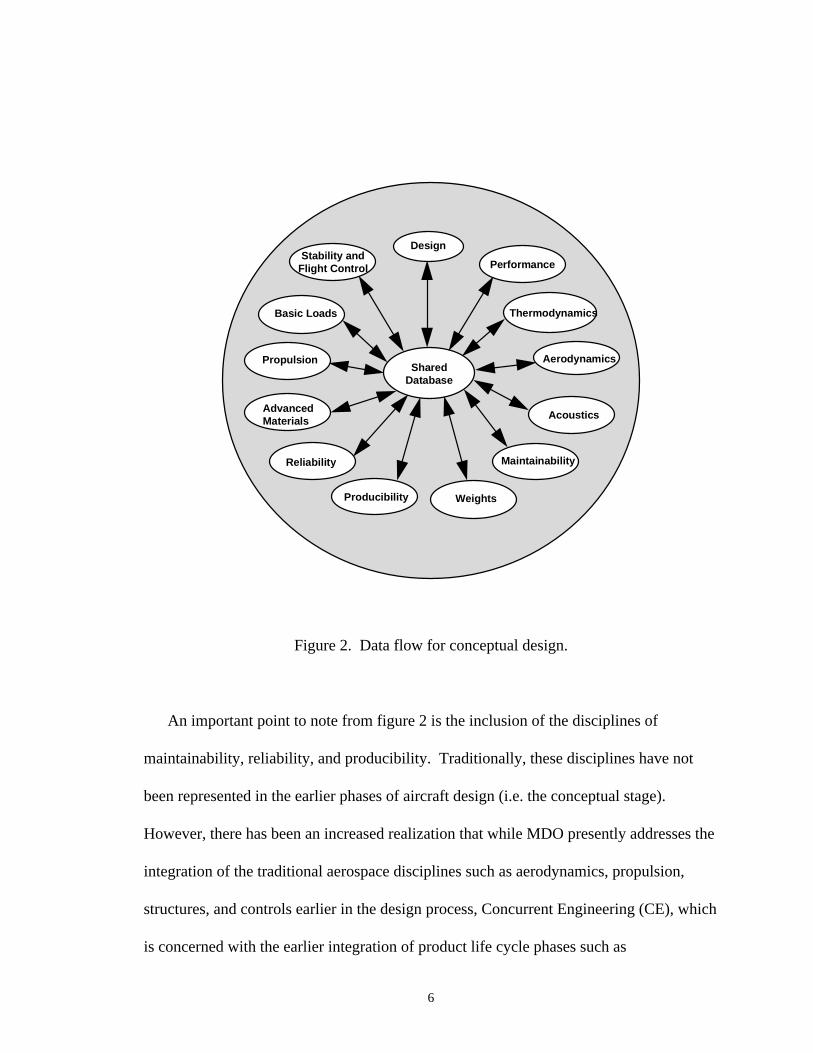
Figure 2 diagrams a data flow structure that is logically centralized around a shared
database and will serve as the model for use in development of proposed approaches and
possible database design strategies for aircraft conceptual design data. This logically
centralized database could also exist as a distributed database.
6
SharedDatabase
Design
Aerodynamics
Stability andFlight Control Performance
Thermodynamics
Acoustics
Weights
Basic Loads
AdvancedMaterials
Propulsion
Reliability
Producibility
Maintainability
Figure 2. Data flow for conceptual design.
An important point to note from figure 2 is the inclusion of the disciplines of
maintainability, reliability, and producibility. Traditionally, these disciplines have not
been represented in the earlier phases of aircraft design (i.e. the conceptual stage).
However, there has been an increased realization that while MDO presently addresses the
integration of the traditional aerospace disciplines such as aerodynamics, propulsion,
structures, and controls earlier in the design process, Concurrent Engineering (CE), which
is concerned with the earlier integration of product life cycle phases such as
7
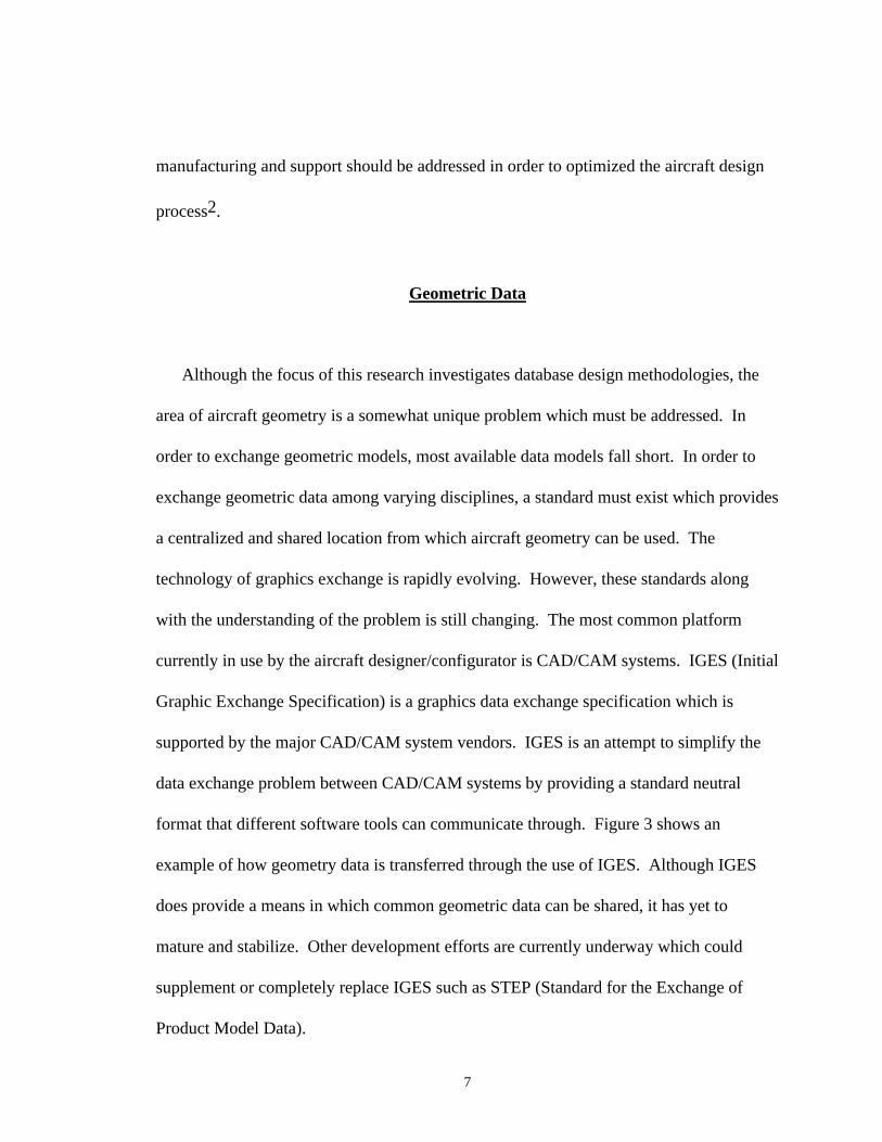
manufacturing and support should be addressed in order to optimized the aircraft design
process2.
Geometric Data
Although the focus of this research investigates database design methodologies, the
area of aircraft geometry is a somewhat unique problem which must be addressed. In
order to exchange geometric models, most available data models fall short. In order to
exchange geometric data among varying disciplines, a standard must exist which provides
a centralized and shared location from which aircraft geometry can be used. The
technology of graphics exchange is rapidly evolving. However, these standards along
with the understanding of the problem is still changing. The most common platform
currently in use by the aircraft designer/configurator is CAD/CAM systems. IGES (Initial
Graphic Exchange Specification) is a graphics data exchange specification which is
supported by the major CAD/CAM system vendors. IGES is an attempt to simplify the
data exchange problem between CAD/CAM systems by providing a standard neutral
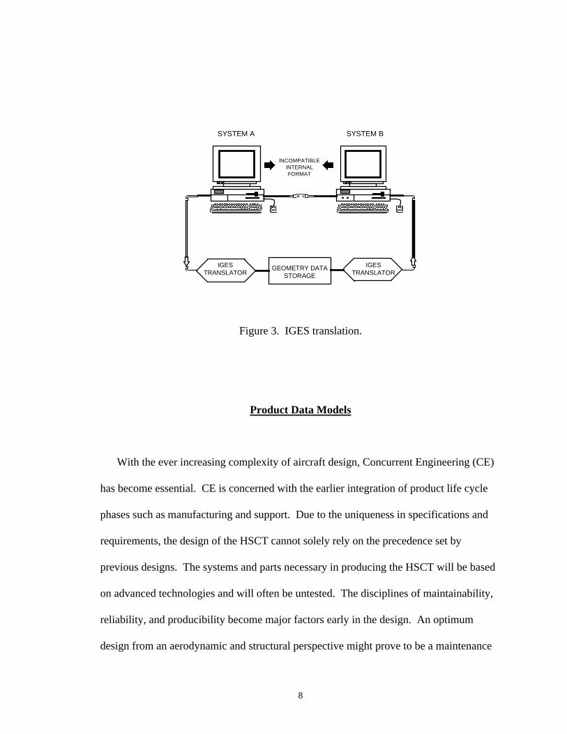
format that different software tools can communicate through. Figure 3 shows an
example of how geometry data is transferred through the use of IGES. Although IGES
does provide a means in which common geometric data can be shared, it has yet to
mature and stabilize. Other development efforts are currently underway which could
supplement or completely replace IGES such as STEP (Standard for the Exchange of
Product Model Data).
8
SYSTEM A SYSTEM B
INCOMPATIBLEINTERNALFORMAT
IGESTRANSLATOR
IGESTRANSLATOR
GEOMETRY DATASTORAGE
Figure 3. IGES translation.
Product Data Models
With the ever increasing complexity of aircraft design, Concurrent Engineering (CE)
has become essential. CE is concerned with the earlier integration of product life cycle
phases such as manufacturing and support. Due to the uniqueness in specifications and
requirements, the design of the HSCT cannot solely rely on the precedence set by
previous designs. The systems and parts necessary in producing the HSCT will be based
on advanced technologies and will often be untested. The disciplines of maintainability,
reliability, and producibility become major factors early in the design. An optimum
design from an aerodynamic and structural perspective might prove to be a maintenance
9
nightmare. Moreover, some parts and systems resulting from the conceptual and
preliminary phases might even prove to be unproduceable from a manufacturing
standpoint. Checks such as these early in the design will save valuable redesign time and
will certainly prove cost effective. The problem of how information for a part or system
is disseminated into the design process must be addressed.
Standardized product data models are gaining acceptance in industry. Numerous
activities are currently underway that address the problem of how to manage product data
from both a design and manufacturing viewpoint. One such activity is PDES (Product
Data Exchange Using Step).
PDES
PDES is an activity whose goal is to create an international standard for the exchange
of product model data. The resulting standard is also a process whereby knowledge is
created, shared, and documented1. PDES is focused on exchanging complete product
models with sufficient information content so as to be interpretable directly by
CAD/CAM application program. It is the intent of the PDES project to fully support the
needs of a complete product model as required by generative process planning systems,
by CAD directed inspection, and by automated numerically control (NC) data
generation5. PDES is an ongoing activity which started off as a spin-off of the IGES

10
activity discussed earlier. STEP (Standard for the Exchange of Product Model Data) is a
set of international standards (drafts) that provide a product data exchange standard to
support life-cycle processes.
11
CHAPTER II
PROCESS MODELING
Surfaced Models
In the earliest phases of a conceptual design, the designer/configurator must create the
geometric lines of the aircraft which define the configuration called a 3-View drawing.
Although still widely used, the 3-View drawing is rapidly being superseded by 3-D
models. The following discussions and the process models presented will include the
creation of the 3-View but it should be noted that this step is being eliminated by most of
the major airframe manufacturers. The 3-View drawing of the configuration definition is
a major product of the design group and serves as the basis for the products provided by
the other technology disciplines (i.e. aerodynamic performance, propulsion, systems,
weight, cost, etc.). Creation of 3-View drawings is an extremely important aspect of the
aircraft process. The 3-View is important in determining the basic design shape of the
aircraft and provides the designer/configurator with a visual representation. The 3-View
also serves as the basis for early performance predictions. Validity of design can be
estimated and candidate configurations can be refined or rejected at this stage. Moreover,
an experienced aircraft designer/configurator can create an aircraft 3-View within a short
time frame and the process is not typically labor intensive. However, with the

12
advancements made in 3-D modelers, a complete 3-dimensional model can be created
with approximately the same effort as the 3-View.
Once the design is partially finalized, the 3-View drawing is then converted into a
surfaced model. An aircraft surfaced model is typically the most common geometric
model supplied by the designer/configurator and used by the technology disciplines and is
very labor intensive to create (this is rapidly becoming less true). However, each
discipline requires differing levels of detail. The aerodynamicist is concerned with
predicting the lift and drag of an aircraft. In order to calculate a preliminary lift and drag,
the aerodynamicist starts with cross-sections created from the surfaced model. The wing
can be collapsed into a planform and used in the various vortex lattice programs
available. Fuselage cross-sectional cuts are used in the prediction of aircraft wave drag.
The structures group is typically interested in a surfaced model which defines the crucial
stress and load points on the aircraft and the "cleanness" of the model is not always
critical. However, the computational fluid dynamist requires a model where line
tangency and abutment are almost always required. Therefore, the surfaced model
provides the various disciplines with a variety of required information.
IDEF0 Model
13
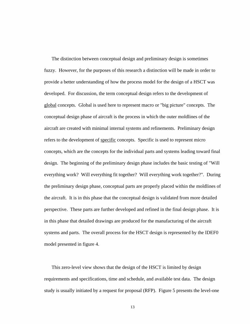
The distinction between conceptual design and preliminary design is sometimes
fuzzy. However, for the purposes of this research a distinction will be made in order to
provide a better understanding of how the process model for the design of a HSCT was
developed. For discussion, the term conceptual design refers to the development of
global concepts. Global is used here to represent macro or "big picture" concepts. The
conceptual design phase of aircraft is the process in which the outer moldlines of the
aircraft are created with minimal internal systems and refinements. Preliminary design
refers to the development of specific concepts. Specific is used to represent micro
concepts, which are the concepts for the individual parts and systems leading toward final
design. The beginning of the preliminary design phase includes the basic testing of "Will
everything work? Will everything fit together? Will everything work together?". During
the preliminary design phase, conceptual parts are properly placed within the moldlines of
the aircraft. It is in this phase that the conceptual design is validated from more detailed
perspective. These parts are further developed and refined in the final design phase. It is
in this phase that detailed drawings are produced for the manufacturing of the aircraft
systems and parts. The overall process for the HSCT design is represented by the IDEF0
model presented in figure 4.
This zero-level view shows that the design of the HSCT is limited by design
requirements and specifications, time and schedule, and available test data. The design
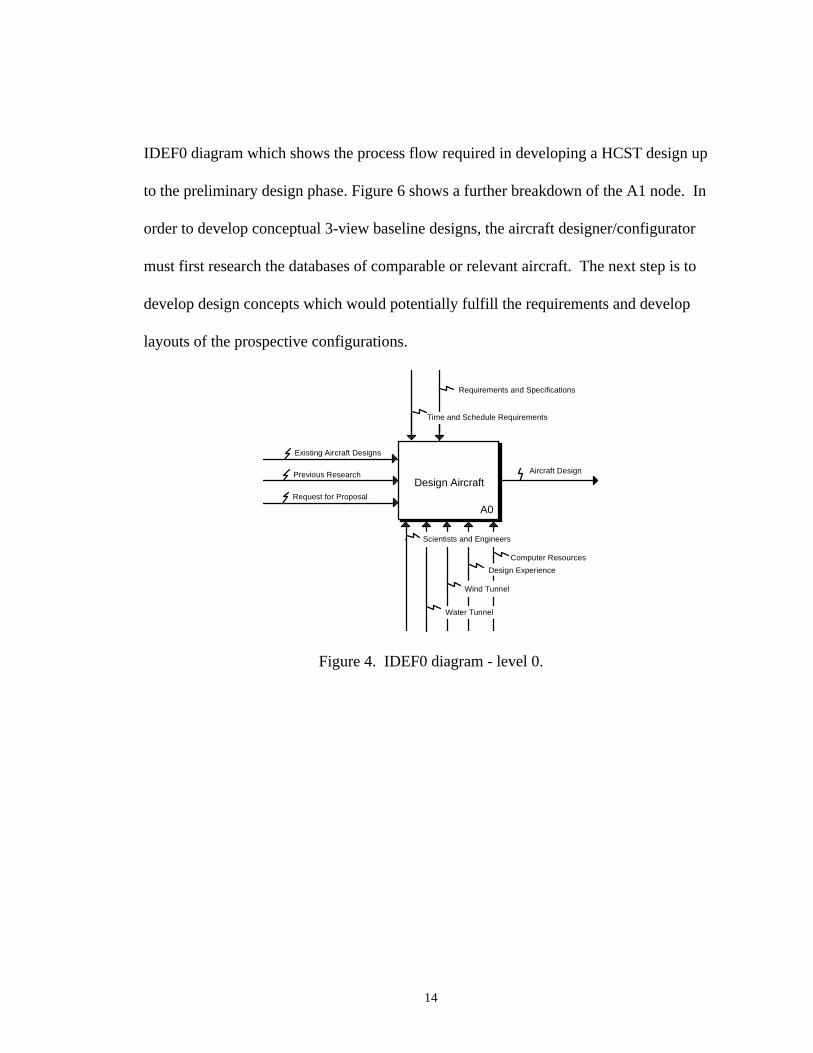
study is usually initiated by a request for proposal (RFP). Figure 5 presents the level-one
14
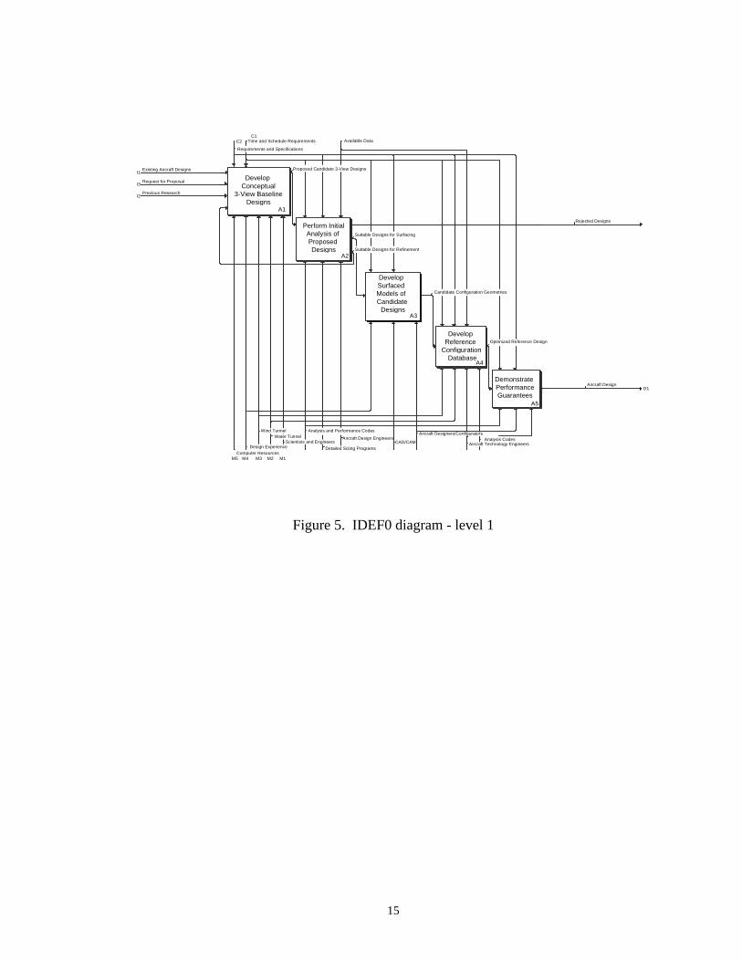
IDEF0 diagram which shows the process flow required in developing a HCST design up
to the preliminary design phase. Figure 6 shows a further breakdown of the A1 node. In
order to develop conceptual 3-view baseline designs, the aircraft designer/configurator
must first research the databases of comparable or relevant aircraft. The next step is to
develop design concepts which would potentially fulfill the requirements and develop
layouts of the prospective configurations.
Design Aircraft
A0Request for Proposal
Existing Aircraft Designs
Previous Research Aircraft Design
Scientists and Engineers
Wind Tunnel
Requirements and Specifications
Computer Resources
Design Experience
Water Tunnel
Time and Schedule Requirements
Figure 4. IDEF0 diagram - level 0.
15
O1
I1
I2
I3
C1C2
M1M2M3M4M5
Demonstrate Performance Guarantees
A5
Develop Reference
Configuration Database
A4
Develop Surfaced Models of Candidate Designs
A3
Perform InitialAnalysis of Proposed Designs
A2
Develop Conceptual
3-View Baseline Designs
A1
Aircraft Design
Rejected Designs
Existing Aircraft Designs
Previous Research
Request for Proposal
Aircraft Technology EngineersAnalysis Codes
CAD/CAM
Available Data
Aircraft Design Engineers
Time and Schedule Requirements
Computer Resources
Aircraft Designers/ConfiguratorsAnalysis and Performance Codes
Design Experience
Wind TunnelWater Tunnel
Scientists and Engineers
Detailed Sizing Programs
Candidate Configuration Geometries
Optimized Reference Design
Suitable Designs for Refinement
Suitable Designs for Surfacing
Proposed Candidate 3-View Designs
Requirements and Specifications
Figure 5. IDEF0 diagram - level 1
16
O1
I1
I2
I3
I4
C1
C2
M1M2M3M4M5
Develop Layouts of Prospective
ConfigurationsA13
Develop Aircraft
ConceptsA12
Research Existing Aircraft
DatabaseA11
Proposed Candidate 3-View Designs
Design Concepts
Existing Aircraft Designs
Request for Proposal
Previous Research
Suitable Designs for Refinement Design Guidlines
CAD/CAM
Aircraft Designers/Configurators
Requirements and Specifications
Time and Schedule Requirements
Computer Resources
Design Experience
Wind TunnelWater Tunnel
Scientists and Engineers
Figure 6. IDEF0 diagram - level 2 block A1.
Figure 7 shows the IDEF0 level 2 process for the A2 node. During this phase of the
design process, early performance, producibility, reliability, maintainability, and cost
analysis are performed based upon the proposed 3-view designs. This is an initial
analysis to provide the aircraft designer/configurator with crucial information regarding
the validity of the design in meeting the requirements and specifications before the labor
intensive job of creating a surfaced model begins.
As a preliminary tool, the aircraft design engineer typically uses preliminary aircraft
performance and sizing programs which attempt to optimize the design based on the

17
inputs of the various disciplines involved. However, care should be taken when using
these codes. There has been a growing realization that in complex engineering systems
the mastery of the interactions among the disciplines and subsystems is as important for
successful designs as technologies used in any individual discipline or subsystem. Early
attempts to solve the problem by wrapping an optimization loop around a set of computer
programs corresponding to the governing disciplines proved disappointing for reason
clear in retrospect3. The approach used tended to exclude the human intellect from the
process, and the computational time and cost of repeated executions of coupled
disciplinary analyses was prohibitive4.
O1
O2
O3
I1
C1C2 C3
M1M2 M3
Perform Cost
AnalysisA26
Perform Reliability and Maintainability
AnalysisA25
Perform Produceability
AnalysisA24
Perform Performance
AnalysisA23
Perform Mass and
Inertia Analysis
A22
Calculate Preliminary
Sizing Parameters
A21
Rejected Designs
Suitable Designs for Surfacing
Suitable Designs for Refinement
Reliability and Maintainability
Produceability
Aircraft Performance
Aircraft Mass and Inertia
Proposed Candidate 3-View Designs Aircraft Sizing Parameters
Costing EngineersManufacturing and Materials EngineersAircraft GeometryAnalysis Codes
Time and Schedule Requirements
Detailed Sizing Programs
Requirements and Specifications
Aircraft Design EngineersAnalysis and Performance Codes
Available Data
Figure 7. IDEF0 diagram - level 2 block A2.
18
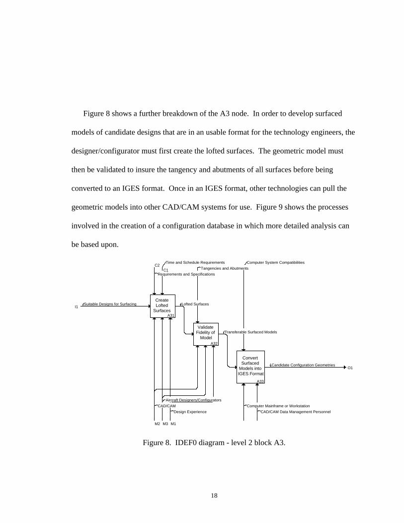
Figure 8 shows a further breakdown of the A3 node. In order to develop surfaced
models of candidate designs that are in an usable format for the technology engineers, the
designer/configurator must first create the lofted surfaces. The geometric model must
then be validated to insure the tangency and abutments of all surfaces before being
converted to an IGES format. Once in an IGES format, other technologies can pull the
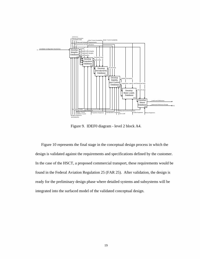
geometric models into other CAD/CAM systems for use. Figure 9 shows the processes
involved in the creation of a configuration database in which more detailed analysis can
be based upon.
O1
I1
C2
M1M2 M3
Convert Surfaced
Models into IGES Format
A33
Validate Fidelity of
ModelA32
Create Lofted
SurfacesA31
Candidate Configuration Geometries
Transferable Surfaced Models
Suitable Designs for Surfacing Lofted Surfaces
Computer System Compatibilities
CAD/CAM Data Management Personnel
Computer Mainframe or Workstation
Tangencies and Abutments
Time and Schedule Requirements
Requirements and Specifications
Design Experience
CAD/CAM
Aircraft Designers/Configurators
C1
Figure 8. IDEF0 diagram - level 2 block A3.
19
O1
I1
Develop Stress
DatabaseA46
Develop Basic Loads
DatabaseA45
Develop Stability
and Control Database
A44
Develop Aerodynamic
DatabaseA43
Develop Propulsion Database
A42
Develop Weights Database
A41
Optimized Reference Design
Loads and Deflections
Aircraft Loads
Longitudinal, Lateral, and Directional Data
Stability Derivatives
Lift and Drag
Engine Deck
Propulsive Drag
Candidate Configuration Geometries
Aircraft Balance
Configuration Weights
Detailed Parts Weights
Inertias
Stress EngineersLoads EngineersDATCOM
Stability and Control Engineers
Water Tunnel AvailabilityWind Tunnel Availability
Propulsion Engineers
Time and Schedule Requirements
Requirements and Specifications
Available Data
Wind Tunnel
Material Information
Weights Engineers
Aerodynamic Engineers
Analysis CodesAircraft Technology Engineers
Water Tunnel
M1M2M3M4
C1C2C3
Figure 9. IDEF0 diagram - level 2 block A4.
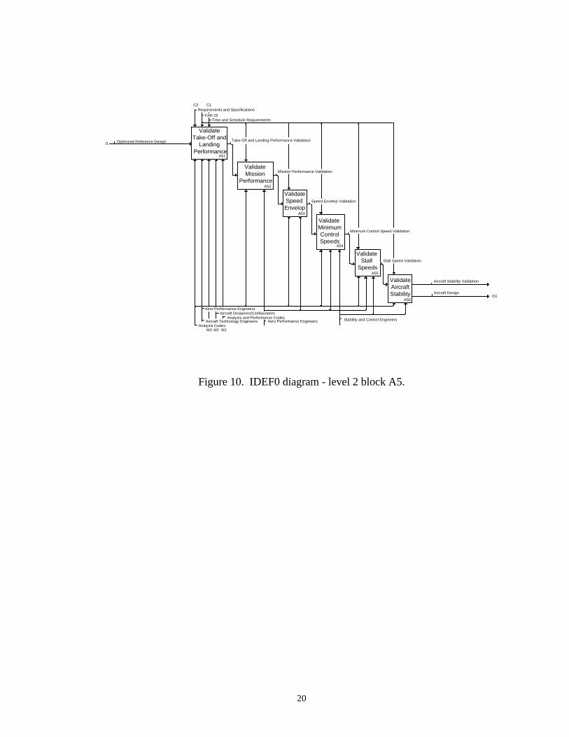
Figure 10 represents the final stage in the conceptual design process in which the
design is validated against the requirements and specifications defined by the customer.
In the case of the HSCT, a proposed commercial transport, these requirements would be
found in the Federal Aviation Regulation 25 (FAR 25). After validation, the design is
ready for the preliminary design phase where detailed systems and subsystems will be
integrated into the surfaced model of the validated conceptual design.
20
O1
I1
C1C2
M1M2M3
Validate Aircraft Stability
A56
Validate Stall
SpeedsA55
Validate Minimum Control Speeds
A54
Validate Speed Envelop
A53
ValidateMission
PerformanceA52
Validate Take-Off and
Landing Performance
A51
Aircraft Design
Aircraft Stability Validation
Stall Speed Validation
Minimum Control Speed Validation
Speed Envelop Validation
Mission Performance Validation
Optimized Reference Design Take-Off and Landing Performance Validation
Stability and Control EngineersAero Performance Engineers
Time and Schedule Requirements
Aircraft Designers/Configurators
Analysis Codes
Aero Performance Engineers
Aircraft Technology EngineersAnalysis and Performance Codes
Requirements and Specifications
FAR 25
Figure 10. IDEF0 diagram - level 2 block A5.
21
CHAPTER III
RELATIONAL DATABASE DESIGN APPROACH
Data Relationships Modeling
The HSCT relational design data model includes the database schema and a data
dictionary. The specific categories for the database design are as follows:
1. Aerodynamics
2. Aircraft Components
3. Cost
4. Materials
5. Performance
6. Stability and Control
7. Weights
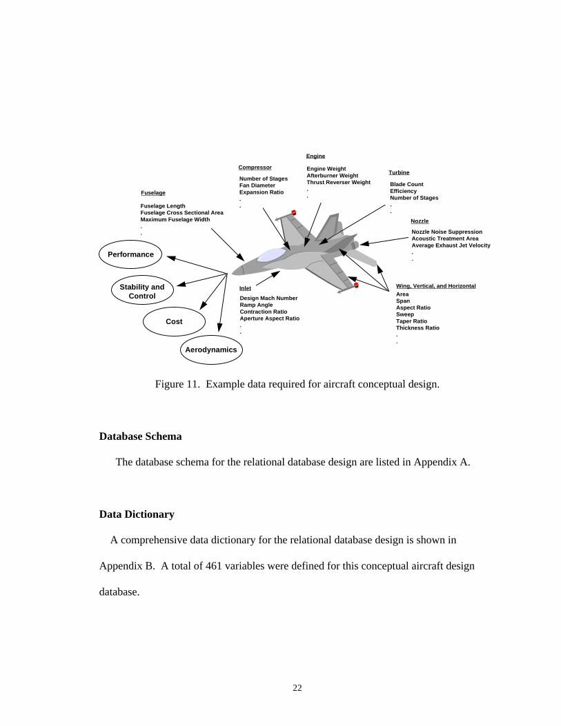
The function model identifies a common process in order to ascertain what the data
requirements are for the conceptual design process. Figure 11 shows examples of the
types of data that are required during the aircraft conceptual design phase.
22
AreaSpanAspect RatioSweepTaper RatioThickness Ratio..
Wing, Vertical, and HorizontalInlet
Design Mach NumberRamp AngleContraction RatioAperture Aspect Ratio..
Nozzle
Nozzle Noise SuppressionAcoustic Treatment AreaAverage Exhaust Jet Velocity..
Fuselage
Fuselage LengthFuselage Cross Sectional AreaMaximum Fuselage Width..
Engine
Engine WeightAfterburner WeightThrust Reverser Weight..
Turbine
Blade CountEfficiencyNumber of Stages..
Compressor
Number of StagesFan DiameterExpansion Ratio..
Performance
Stability andControl
Cost
Aerodynamics
Figure 11. Example data required for aircraft conceptual design.
Database Schema
The database schema for the relational database design are listed in Appendix A.
Data Dictionary
A comprehensive data dictionary for the relational database design is shown in
Appendix B. A total of 461 variables were defined for this conceptual aircraft design
database.
23
Normal Forms in Relational Design
In order to avoid data redundancy in the relation design, relational tables are further
normalized beyond the first normal form ( 1NF ). The first normal form is defined as a
relation that has atomic or single-valued attributes, i.e. only one value for a given row and
column in a relational table. This normalization alleviates many problems that typically
arise during updates when data redundancy exists. C. J. Date describes a good relational
design principle as “one fact in one place”.21 Numerous normal forms have been defined
by relational database experts. The first three normal forms ( 1NF, 2NF, 3NF ) were
defined by Codd in reference 22. The motivation behind Codd’s definitions was that 2NF
was “more desirable” than 1NF, and 3NF in turn was more desirable than 2NF. That is,
the database designer should generally aim for a design involving relations in 3NF, not
relations that are merely 2NF or 1NF.21 However, Codd’s original definition of 3NF
turned out to suffer from certain inadequacies. These inadequacies led to the revision of
Codd’s original 3NF definition and the creation of a stronger definition known as the
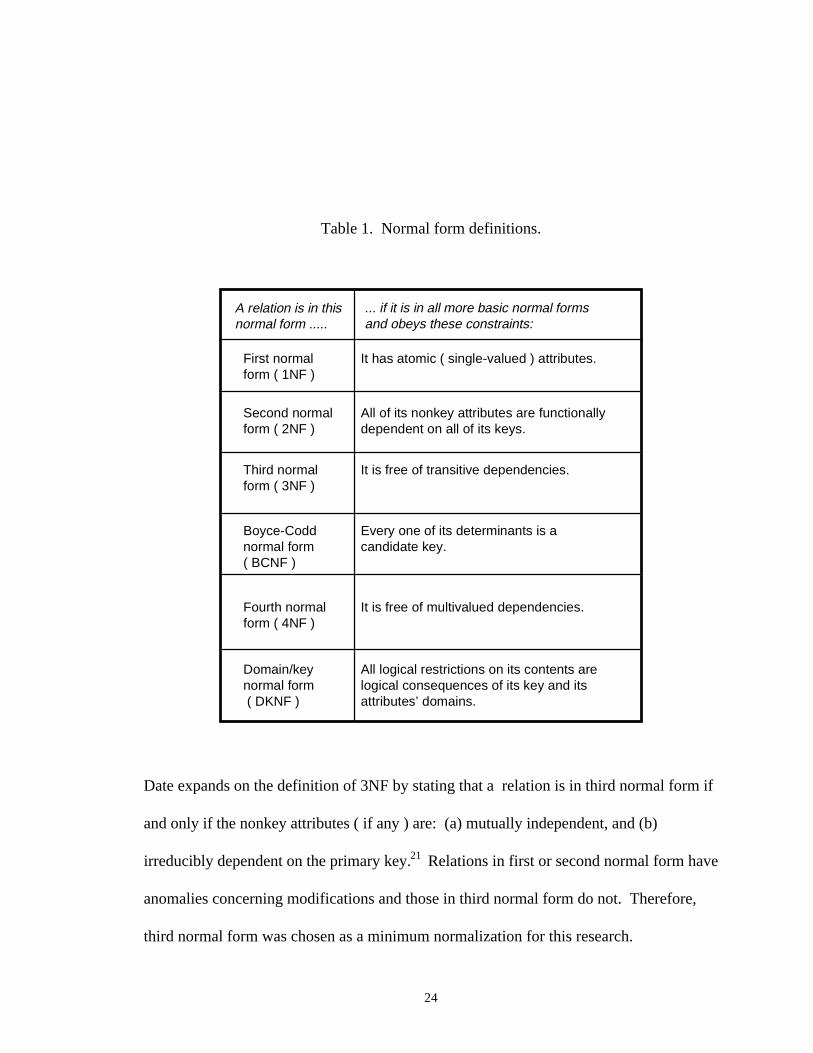
Boyce-Codd normal form ( BCNF ). Table 1 shows the ascending series of normal
forms.
24
Table 1. Normal form definitions.
A relation is in thisnormal form .....
... if it is in all more basic normal formsand obeys these constraints:
First normalform ( 1NF )
Second normalform ( 2NF )
Third normalform ( 3NF )
Boyce-Coddnormal form( BCNF )
Fourth normalform ( 4NF )
Domain/keynormal form ( DKNF )
It has atomic ( single-valued ) attributes.
All of its nonkey attributes are functionallydependent on all of its keys.
It is free of transitive dependencies.
Every one of its determinants is a candidate key.
It is free of multivalued dependencies.
All logical restrictions on its contents arelogical consequences of its key and itsattributes’ domains.
Date expands on the definition of 3NF by stating that a relation is in third normal form if
and only if the nonkey attributes ( if any ) are: (a) mutually independent, and (b)
irreducibly dependent on the primary key.21 Relations in first or second normal form have
anomalies concerning modifications and those in third normal form do not. Therefore,
third normal form was chosen as a minimum normalization for this research.
25
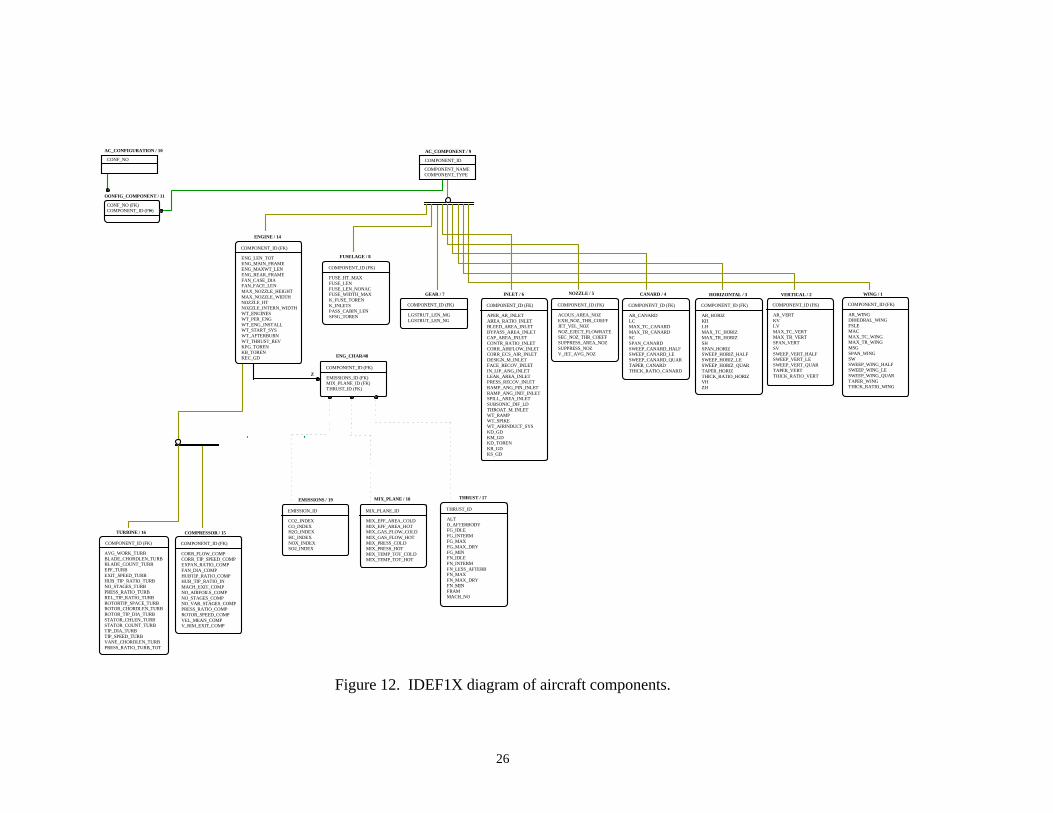
Logical Database Design ( IDEF1X )
Figure 12 shows the IDEF1X model for the aircraft components. An aircraft
configuration is made up of components. For this application those components are the:
engine, fuselage, gear, inlet, nozzle, canard, horizontal, vertical, and wing.
26
AC_CONFIGURATION / 10 AC_COMPONENT / 9
CONFIG_COMPONENT / 11
WING / 1VERTICAL / 2HORIZONTAL / 3CANARD / 4NOZZLE / 5INLET / 6GEAR / 7
FUSELAGE / 8
ENGINE / 14
COMPRESSOR / 15TURBINE / 16
ENG_LEN_TOTENG_MAIN_FRAMEENG_MAXWT_LENENG_REAR_FRAMEFAN_CASE_DIAFAN_FACE_LENMAX_NOZZLE_HEIGHTMAX_NOZZLE_WIDTHNOZZLE_HTNOZZLE_INTERN_WIDTHWT_ENGINESWT_PER_ENGWT_ENG_INSTALLWT_START_SYSWT_AFTERBURNWT_THRUST_REVKPG_TORENKB_TORENKEC_GD
COMPONENT_ID (FK)
FUSE_HT_MAXFUSE_LENFUSE_LEN_NONACFUSE_WIDTH_MAXK_FUSE_TORENK_INLETSPASS_CABIN_LENSFSG_TOREN
COMPONENT_ID (FK)
LGSTRUT_LEN_MGLGSTRUT_LEN_NG
COMPONENT_ID (FK)
APER_AR_INLETAREA_RATIO_INLETBLEED_AREA_INLETBYPASS_AREA_INLETCAP_AREA_INLETCONTR_RATIO_INLETCORR_AIRFLOW_INLETCORR_ECS_AIR_INLETDESIGN_M_INLETFACE_RECOV_INLETIN_LIP_ANG_INLETLEAK_AREA_INLETPRESS_RECOV_INLETRAMP_ANG_FIN_INLETRAMP_ANG_INIT_INLETSPILL_AREA_INLETSUBSONIC_DIF_LDTHROAT_M_INLETWT_RAMPWT_SPIKEWT_AIRINDUCT_SYSKD_GDKM_GDKD_TORENKR_GDKS_GD
COMPONENT_ID (FK)
ACOUS_AREA_NOZEXH_NOZ_THR_COEFFJET_VEL_NOZNOZ_EJECT_FLOWRATESEC_NOZ_THR_COEFFSUPPRESS_AREA_NOZSUPPRESS_NOZV_JET_AVG_NOZ
COMPONENT_ID (FK)
AR_CANARDLCMAX_TC_CANARDMAX_TR_CANARDSCSPAN_CANARDSWEEP_CANARD_HALFSWEEP_CANARD_LESWEEP_CANARD_QUARTAPER_CANARDTHICK_RATIO_CANARD
COMPONENT_ID (FK)
AR_HORIZKHLHMAX_TC_HORIZMAX_TR_HORIZSHSPAN_HORIZSWEEP_HORIZ_HALFSWEEP_HORIZ_LESWEEP_HORIZ_QUARTAPER_HORIZTHICK_RATIO_HORIZVHZH
COMPONENT_ID (FK)
AR_VERTKVLVMAX_TC_VERTMAX_TR_VERTSPAN_VERTSVSWEEP_VERT_HALFSWEEP_VERT_LESWEEP_VERT_QUARTAPER_VERTTHICK_RATIO_VERT
COMPONENT_ID (FK)
AR_WINGDIHEDRAL_WINGFSLEMACMAX_TC_WINGMAX_TR_WINGMSGSPAN_WINGSWSWEEP_WING_HALFSWEEP_WING_LESWEEP_WING_QUARTAPER_WINGTHICK_RATIO_WING
COMPONENT_ID (FK)
COMPONENT_ID
COMPONENT_NAMECOMPONENT_TYPE
CONF_NO
CONF_NO (FK)COMPONENT_ID (FK)
EMISSIONS / 19
CO2_INDEXCO_INDEXH2O_INDEXHC_INDEXNOX_INDEXSO2_INDEX
EMISSION_ID
MIX_PLANE / 18
Z
MIX_EFF_AREA_COLDMIX_EFF_AREA_HOTMIX_GAS_FLOW_COLDMIX_GAS_FLOW_HOTMIX_PRESS_COLDMIX_PRESS_HOTMIX_TEMP_TOT_COLDMIX_TEMP_TOT_HOT
MIX_PLANE_ID
THRUST / 17Z
ALTD_AFTERBODYFG_IDLEFG_INTERMFG_MAXFG_MAX_DRYFG_MINFN_IDLEFN_INTERMFN_LESS_AFTERBFN_MAXFN_MAX_DRYFN_MINFRAMMACH_NO
THRUST_ID
Z
CORR_FLOW_COMPCORR_TIP_SPEED_COMPEXPAN_RATIO_COMPFAN_DIA_COMPHUBTIP_RATIO_COMPHUB_TIP_RATIO_INMACH_EXIT_COMPNO_AIRFOILS_COMPNO_STAGES_COMPNO_VAR_STAGES_COMPPRESS_RATIO_COMPROTOR_SPEED_COMPVEL_MEAN_COMPV_RIM_EXIT_COMP
COMPONENT_ID (FK)Z
AVG_WORK_TURBBLADE_CHORDLEN_TURBBLADE_COUNT_TURBEFF_TURBEXIT_SPEED_TURBHUB_TIP_RATIO_TURBNO_STAGES_TURBPRESS_RATIO_TURBREL_TIP_RATIO_TURBROTORTIP_SPACE_TURBROTOR_CHORDLEN_TURBROTOR_TIP_DIA_TURBSTATOR_CHLEN_TURBSTATOR_COUNT_TURBTIP_DIA_TURBTIP_SPEED_TURBVANE_CHORDLEN_TURBPRESS_RATIO_TURB_TOT
COMPONENT_ID (FK)
EMISSIONS_ID (FK)MIX_PLANE_ID (FK)THRUST_ID (FK)
COMPONENT_ID (FK)
ENG_CHAR/48
Z
Figure 12. IDEF1X diagram of aircraft components.
27
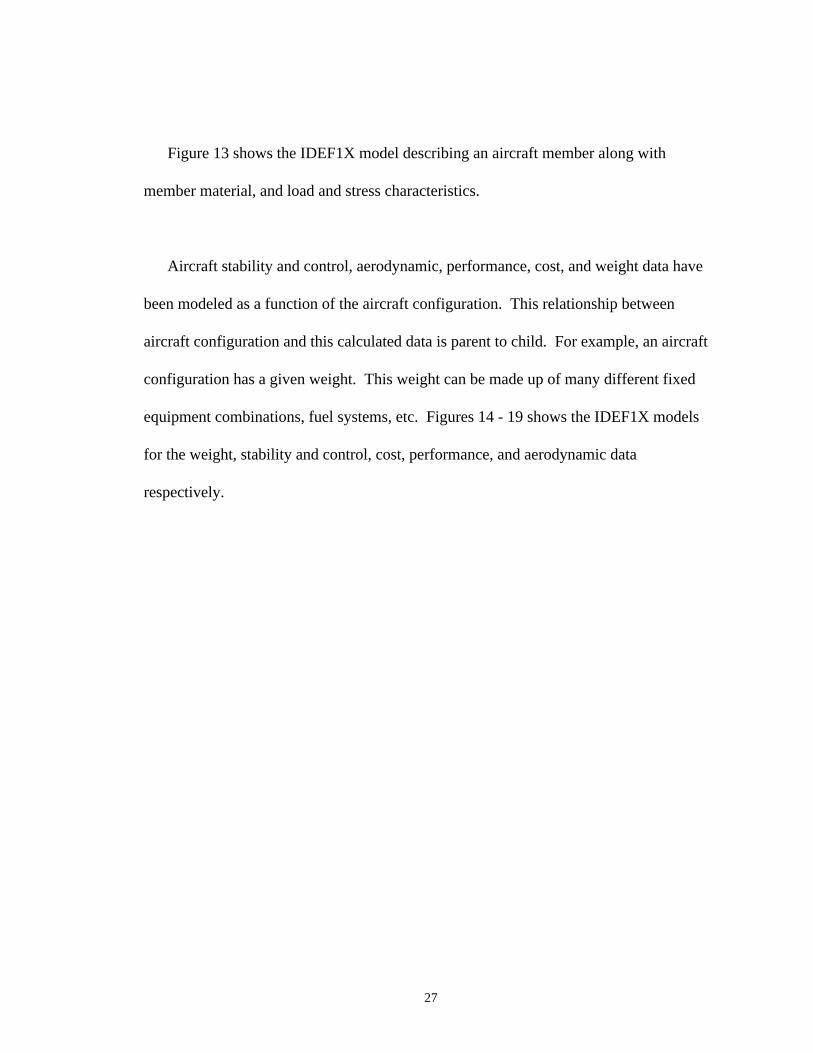
Figure 13 shows the IDEF1X model describing an aircraft member along with
member material, and load and stress characteristics.
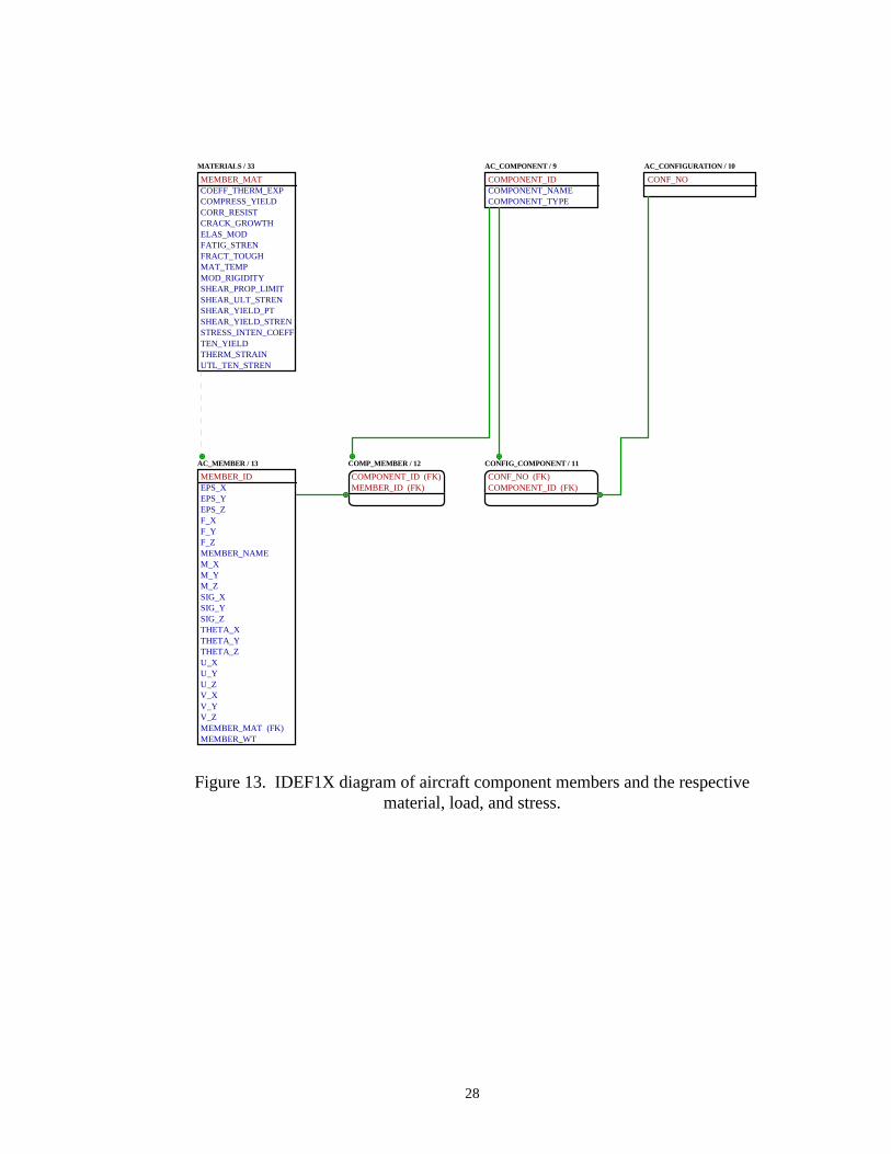
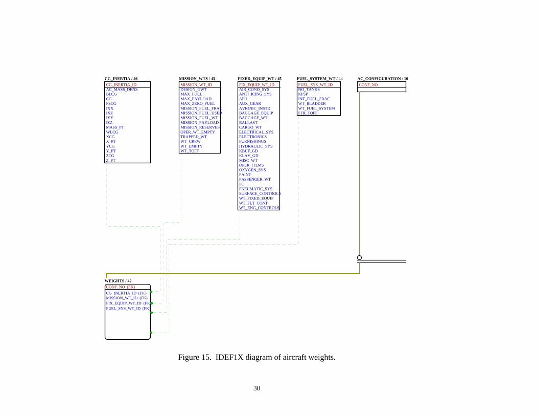
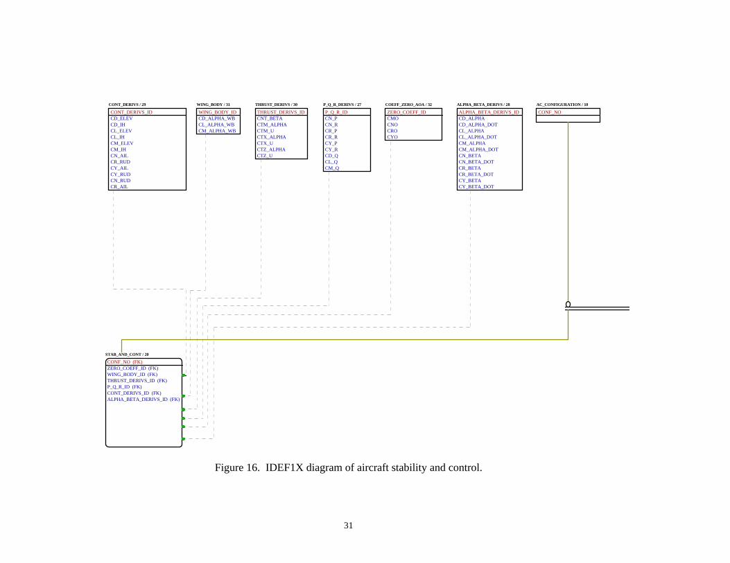
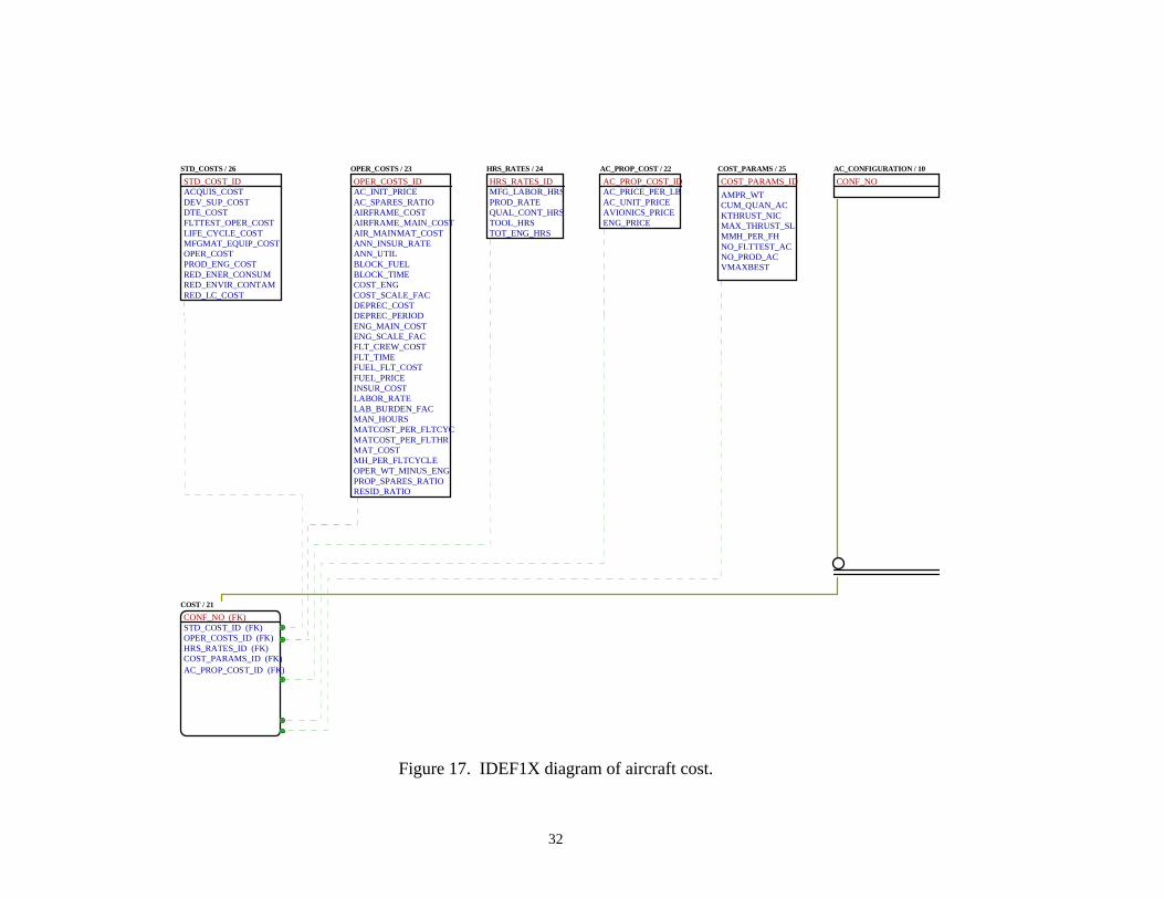
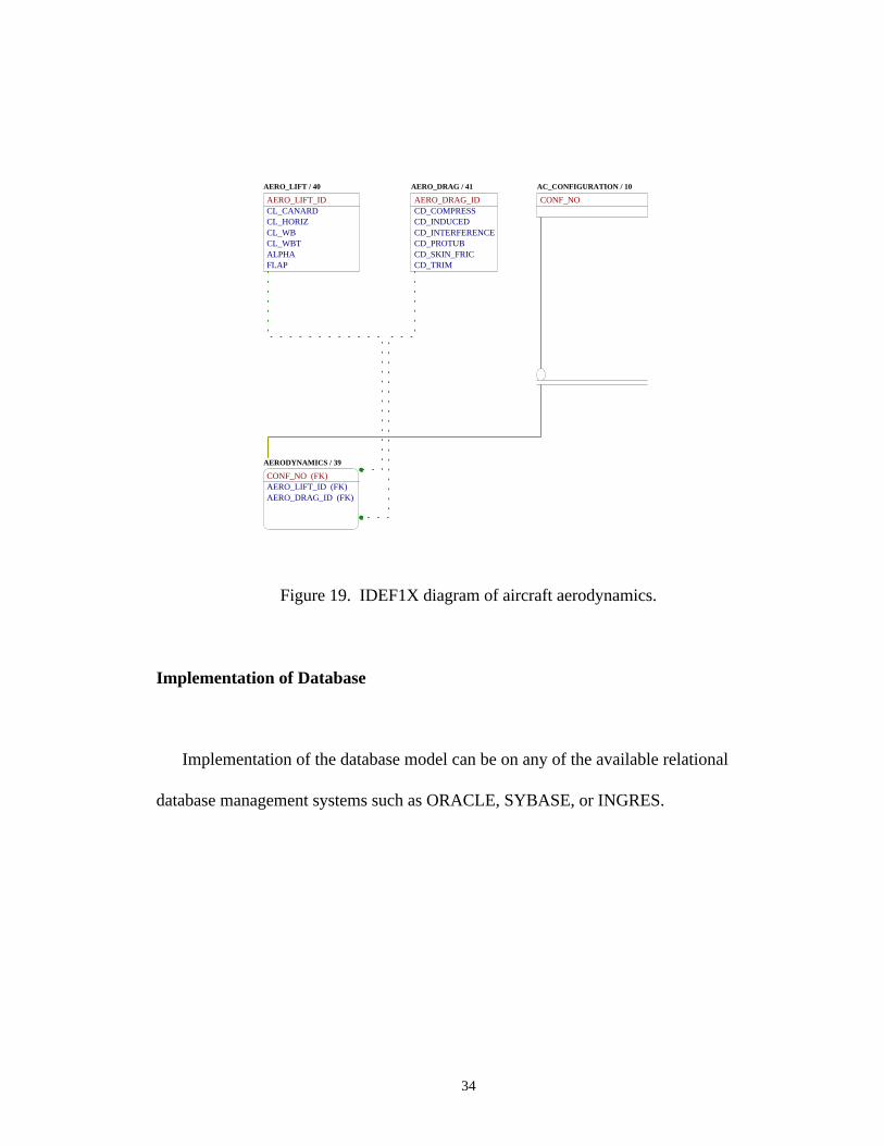
Aircraft stability and control, aerodynamic, performance, cost, and weight data have
been modeled as a function of the aircraft configuration. This relationship between
aircraft configuration and this calculated data is parent to child. For example, an aircraft
configuration has a given weight. This weight can be made up of many different fixed
equipment combinations, fuel systems, etc. Figures 14 - 19 shows the IDEF1X models
for the weight, stability and control, cost, performance, and aerodynamic data
respectively.
28
MATERIALS / 33
MEMBER_MATCOEFF_THERM_EXPCOMPRESS_YIELDCORR_RESISTCRACK_GROWTHELAS_MODFATIG_STRENFRACT_TOUGHMAT_TEMPMOD_RIGIDITYSHEAR_PROP_LIMITSHEAR_ULT_STRENSHEAR_YIELD_PTSHEAR_YIELD_STRENSTRESS_INTEN_COEFFTEN_YIELDTHERM_STRAINUTL_TEN_STREN
AC_COMPONENT / 9
COMPONENT_IDCOMPONENT_NAMECOMPONENT_TYPE
AC_CONFIGURATION / 10
CONF_NO
CONFIG_COMPONENT / 11
CONF_NO (FK)COMPONENT_ID (FK)
COMP_MEMBER / 12
COMPONENT_ID (FK)MEMBER_ID (FK)
AC_MEMBER / 13
MEMBER_IDEPS_XEPS_YEPS_ZF_XF_YF_ZMEMBER_NAMEM_XM_YM_ZSIG_XSIG_YSIG_ZTHETA_XTHETA_YTHETA_ZU_XU_YU_ZV_XV_YV_ZMEMBER_MAT (FK)MEMBER_WT
Figure 13. IDEF1X diagram of aircraft component members and the respectivematerial, load, and stress.
29
AC_CONFIGURATION / 10
CONF_NO
STAB_AND_CONT / 20
CONF_NO (FK)ZERO_COEFF_ID (FK)WING_BODY_ID (FK)THRUST_DERIVS_ID (FK)P_Q_R_ID (FK)CONT_DERIVS_ID (FK)ALPHA_BETA_DERIVS_ID (FK)
COST / 21
CONF_NO (FK)STD_COST_ID (FK)OPER_COSTS_ID (FK)HRS_RATES_ID (FK)COST_PARAMS_ID (FK)AC_PROP_COST_ID (FK)
PERFORMANCE / 34
CONF_NO (FK)SPEED_ID (FK)PERF_MEAS_ID (FK)LIMITS_ID (FK)DISTANCES_ID (FK)
AERODYNAMICS / 39
CONF_NO (FK)AERO_LIFT_ID (FK)AERO_DRAG_ID (FK)
WEIGHTS / 42
CONF_NO (FK)CG_INERTIA_ID (FK)MISSION_WT_ID (FK)FIX_EQUIP_WT_ID (FK)FUEL_SYS_WT_ID (FK)
Figure 14. IDEF1X diagram of aircraft discipline calculations.
30
CG_INERTIA / 46
CG_INERTIA_IDAC_MASS_DENSBLCGCGFSCGIXXIXZIYYIZZMASS_PTWLCGXCGX_PTYCGY_PTZCGZ_PT
MISSION_WTS / 43
MISSION_WT_IDDESIGN_GWTMAX_FUELMAX_PAYLOADMAX_ZERO_FUELMISSION_FUEL_FRACMISSION_FUEL_USEDMISSION_FUEL_WTMISSION_PAYLOADMISSION_RESERVESOPER_WT_EMPTYTRAPPED_WTWT_CREWWT_EMPTYWT_TOFF
FIXED_EQUIP_WT / 45
FIX_EQUIP_WT_IDAIR_COND_SYSANTI_ICING_SYSAPUAUX_GEARAVIONIC_INSTRBAGGAGE_EQUIPBAGGAGE_WTBALLASTCARGO_WTELECTRICAL_SYSELECTRONICSFURNISHINGSHYDRAULIC_SYSKBUF_GDKLAV_GDMISC_WTOPER_ITEMSOXYGEN_SYSPAINTPASSENGER_WTPCPNEUMATIC_SYSSURFACE_CONTROLSWT_FIXED_EQUIPWT_FLT_CONTWT_ENG_CONTROLS
FUEL_SYSTEM_WT / 44
FUEL_SYS_WT_IDNO_TANKSKFSPINT_FUEL_FRACWT_BLADDERWT_FUEL_SYSTEMFFR_TOFF
AC_CONFIGURATION / 10
CONF_NO
WEIGHTS / 42
CONF_NO (FK)
CG_INERTIA_ID (FK)MISSION_WT_ID (FK)FIX_EQUIP_WT_ID (FK)FUEL_SYS_WT_ID (FK)
Figure 15. IDEF1X diagram of aircraft weights.
31
CONT_DERIVS / 29
CONT_DERIVS_IDCD_ELEVCD_IHCL_ELEVCL_IHCM_ELEVCM_IHCN_AILCR_RUDCY_AILCY_RUDCN_RUDCR_AIL
WING_BODY / 31
WING_BODY_IDCD_ALPHA_WBCL_ALPHA_WBCM_ALPHA_WB
THRUST_DERIVS / 30
THRUST_DERIVS_IDCNT_BETACTM_ALPHACTM_UCTX_ALPHACTX_UCTZ_ALPHACTZ_U
P_Q_R_DERIVS / 27
P_Q_R_IDCN_PCN_RCR_PCR_RCY_PCY_RCD_QCL_QCM_Q
COEFF_ZERO_AOA / 32
ZERO_COEFF_IDCMOCNOCROCYO
ALPHA_BETA_DERIVS / 28
ALPHA_BETA_DERIVS_IDCD_ALPHACD_ALPHA_DOTCL_ALPHACL_ALPHA_DOTCM_ALPHACM_ALPHA_DOTCN_BETACN_BETA_DOTCR_BETACR_BETA_DOTCY_BETACY_BETA_DOT
AC_CONFIGURATION / 10
CONF_NO
STAB_AND_CONT / 20
CONF_NO (FK)ZERO_COEFF_ID (FK)WING_BODY_ID (FK)
P_Q_R_ID (FK)CONT_DERIVS_ID (FK)
THRUST_DERIVS_ID (FK)
ALPHA_BETA_DERIVS_ID (FK)
Figure 16. IDEF1X diagram of aircraft stability and control.
32
STD_COSTS / 26
STD_COST_IDACQUIS_COSTDEV_SUP_COSTDTE_COSTFLTTEST_OPER_COSTLIFE_CYCLE_COSTMFGMAT_EQUIP_COSTOPER_COSTPROD_ENG_COSTRED_ENER_CONSUMRED_ENVIR_CONTAMRED_LC_COST
OPER_COSTS / 23
OPER_COSTS_IDAC_INIT_PRICEAC_SPARES_RATIOAIRFRAME_COSTAIRFRAME_MAIN_COSTAIR_MAINMAT_COSTANN_INSUR_RATEANN_UTILBLOCK_FUELBLOCK_TIMECOST_ENGCOST_SCALE_FACDEPREC_COSTDEPREC_PERIODENG_MAIN_COSTENG_SCALE_FACFLT_CREW_COSTFLT_TIMEFUEL_FLT_COSTFUEL_PRICEINSUR_COSTLABOR_RATELAB_BURDEN_FACMAN_HOURSMATCOST_PER_FLTCYCMATCOST_PER_FLTHRMAT_COSTMH_PER_FLTCYCLEOPER_WT_MINUS_ENGPROP_SPARES_RATIORESID_RATIO
HRS_RATES / 24
HRS_RATES_IDMFG_LABOR_HRSPROD_RATEQUAL_CONT_HRSTOOL_HRSTOT_ENG_HRS
AC_PROP_COST / 22
AC_PROP_COST_IDAC_PRICE_PER_LBAC_UNIT_PRICEAVIONICS_PRICEENG_PRICE
COST_PARAMS / 25
COST_PARAMS_ID
AMPR_WTCUM_QUAN_ACKTHRUST_NICMAX_THRUST_SLMMH_PER_FHNO_FLTTEST_ACNO_PROD_ACVMAXBEST
AC_CONFIGURATION / 10
CONF_NO
COST / 21
CONF_NO (FK)STD_COST_ID (FK)OPER_COSTS_ID (FK)HRS_RATES_ID (FK)COST_PARAMS_ID (FK)AC_PROP_COST_ID (FK)
Figure 17. IDEF1X diagram of aircraft cost.

33
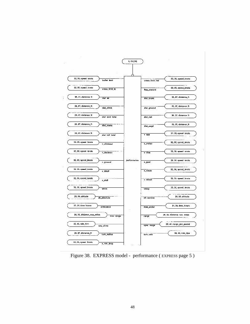
AC_CONFIGURATION / 10
CONF_NO
LIMITS / 37
LIMITS_IDBUFFET_LIMITCROSS_LIMIT_LNDCROSS_LIMIT_TOFLAP_PLACARD
DISTANCES / 35
DISTANCES_IDDIST_AIRDIST_BRAKEDIST_CLIMBDIST_GROUNDDIST_LAND_TOTALDIST_ROLLDIST_ROTATEDIST_SEGDDIST_TOFF_TOTAL
SPEEDS / 36
SPEED_IDV_APPV_CLIMBOUTV_CRUISEV_DECISIONV_DIVEV_GROUNDV_GUSTV_LIFTOFFV_ROTATEV_STALLV_TDOWNVMCAVMCG
PERF_MEASURES / 38
PERF_MEAS_IDALT_ABSOULTEALT_SERVICEENDURANCEMAX_ENDURMAX_RANGERANGERATE_CLIMBSPEC_RANGETURN_RADIUSTURN_RATEV_MIN_DRAG
PERFORMANCE / 34
CONF_NO (FK)SPEED_ID (FK)PERF_MEAS_ID (FK)LIMITS_ID (FK)DISTANCES_ID (FK)
Figure 18. IDEF1X diagram of aircraft performance.
34
AERO_LIFT / 40
AERO_LIFT_IDCL_CANARDCL_HORIZCL_WBCL_WBTALPHAFLAP
AERO_DRAG / 41
AERO_DRAG_IDCD_COMPRESSCD_INDUCEDCD_INTERFERENCECD_PROTUBCD_SKIN_FRICCD_TRIM
AC_CONFIGURATION / 10
CONF_NO
AERODYNAMICS / 39
CONF_NO (FK)AERO_LIFT_ID (FK)AERO_DRAG_ID (FK)
Figure 19. IDEF1X diagram of aircraft aerodynamics.
Implementation of Database
Implementation of the database model can be on any of the available relational
database management systems such as ORACLE, SYBASE, or INGRES.
35
CHAPTER IV
OBJECT-ORIENTED DATABASE DESIGN APPROACH
Data Relationships Modeling
The design treats an aircraft configuration as a object which is composed of other
component objects. The objects making up an aircraft configuration are a: wing,
horizontal, vertical, canard, fuselage, engine, nozzle, inlet, and gear. An engine is made
up of a compressor and a turbine. Each of the aircraft component’s objects are made up
of member objects which have load, stress, and material characteristics. The typically
disciplinary calculations of aerodynamics, cost, weights, performance, and stability and
control are treated as objects of an aircraft configuration. This seems a little unnatural,
however, these calculations have been traditionally grouped by discipline and it is
probably a good guess that they will continue to be associated in this manner for some
time to come.
Database Schema
The lexical EXPRESS model for the Object-Oriented design is shown in Appendix C.

36
Data Dictionary
The HSCT object-oriented design data model utilizes the same data dictionary as the
relational design found in Appendix B.
Logical Database Design ( EXPRESS )
Figure 20 shows the EXPRESS model for the aircraft components. Different from
the relational design, the aircraft configuration object ( ac_configuration ) has attributes
that extend beyond simple data types. The disciplinary calculations of costs, weights,
aerodynamics, performance, and stability and control are considered attributes of aircraft
configuration. Another important point is that a uniqueness constraint exists for the
simple data type of identification_no. This identification number is inherited by the
disciplinary calculation objects as well as the aircraft components ( ac_component ).
Figure 20. EXPRESS model -aircraft configuration ( EXPRESS page 19 )
37
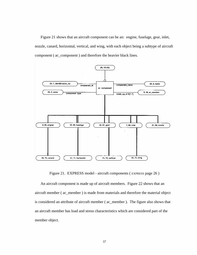
Figure 21 shows that an aircraft component can be an: engine, fuselage, gear, inlet,
nozzle, canard, horizontal, vertical, and wing, with each object being a subtype of aircraft
component ( ac_component ) and therefore the heavier black lines.
Figure 21. EXPRESS model - aircraft components ( EXPRESS page 26 )
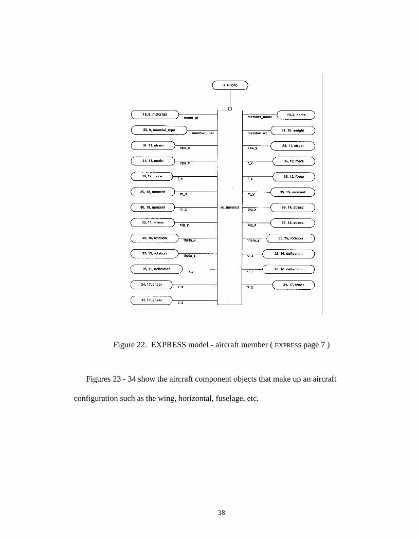
An aircraft component is made up of aircraft members. Figure 22 shows that an
aircraft member ( ac_member ) is made from materials and therefore the material object
is considered an attribute of aircraft member ( ac_member ). The figure also shows that
an aircraft member has load and stress characteristics which are considered part of the
member object.
38
Figure 22. EXPRESS model - aircraft member ( EXPRESS page 7 )
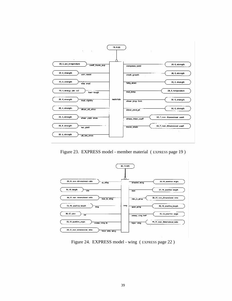
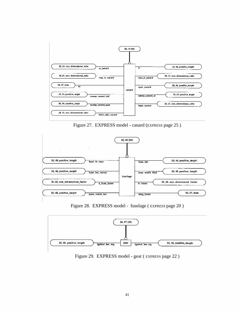
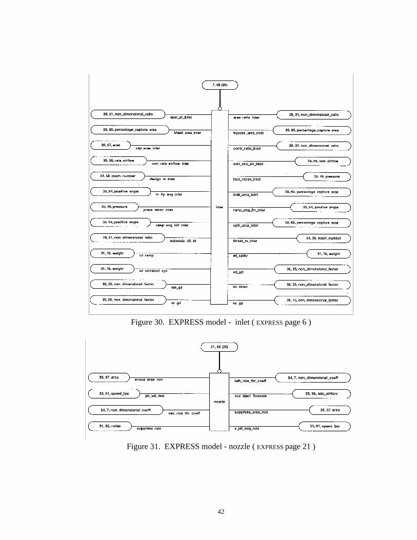
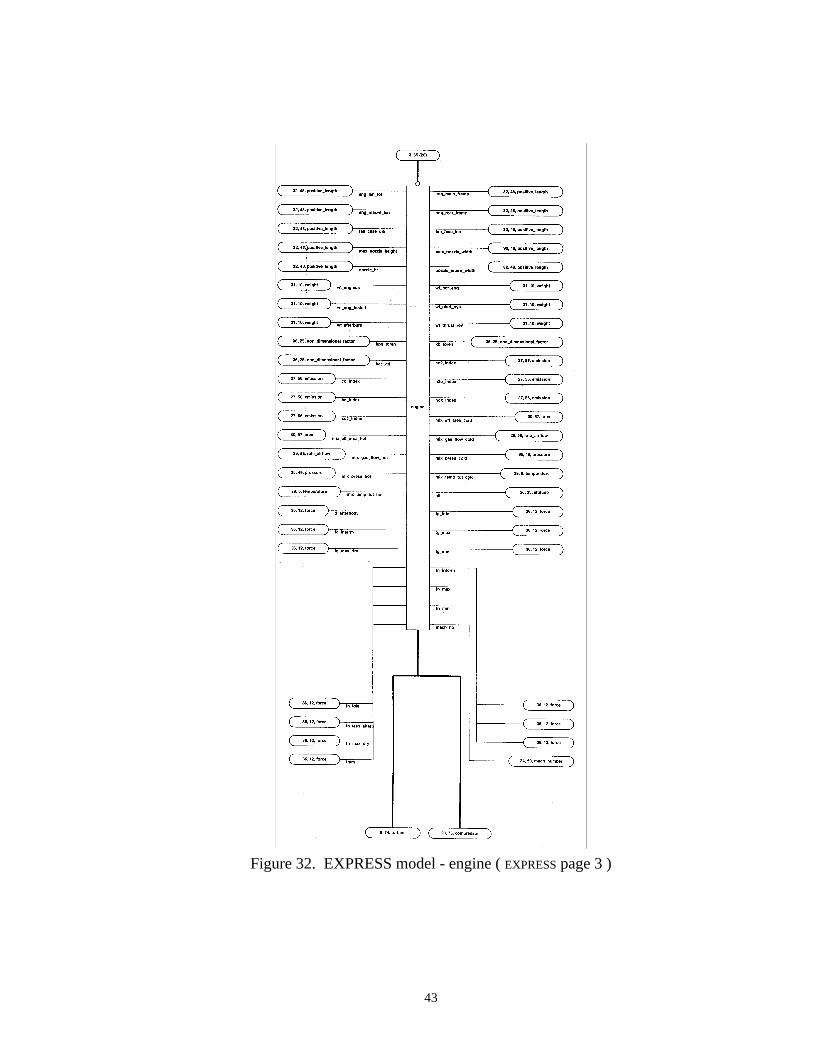
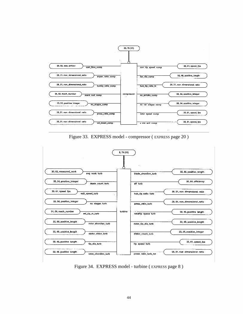
Figures 23 - 34 show the aircraft component objects that make up an aircraft
configuration such as the wing, horizontal, fuselage, etc.
39
Figure 23. EXPRESS model - member material ( EXPRESS page 19 )
Figure 24. EXPRESS model - wing ( EXPRESS page 22 )
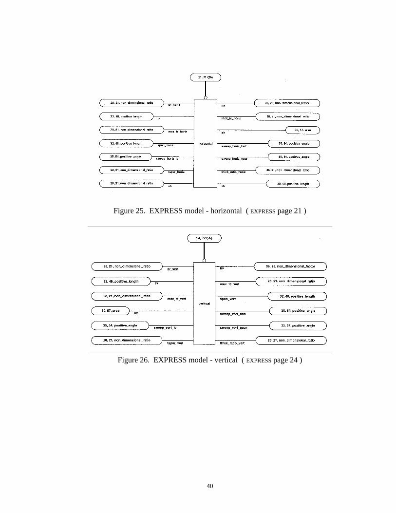
40
Figure 25. EXPRESS model - horizontal ( EXPRESS page 21 )
Figure 26. EXPRESS model - vertical ( EXPRESS page 24 )
41
Figure 27. EXPRESS model - canard (EXPRESS page 25 )
Figure 28. EXPRESS model - fuselage ( EXPRESS page 20 )
Figure 29. EXPRESS model - gear ( EXPRESS page 22 )
42
Figure 30. EXPRESS model - inlet ( EXPRESS page 6 )
Figure 31. EXPRESS model - nozzle ( EXPRESS page 21 )
43
Figure 32. EXPRESS model - engine ( EXPRESS page 3 )
44
Figure 33. EXPRESS model - compressor ( EXPRESS page 20 )
Figure 34. EXPRESS model - turbine ( EXPRESS page 8 )
45
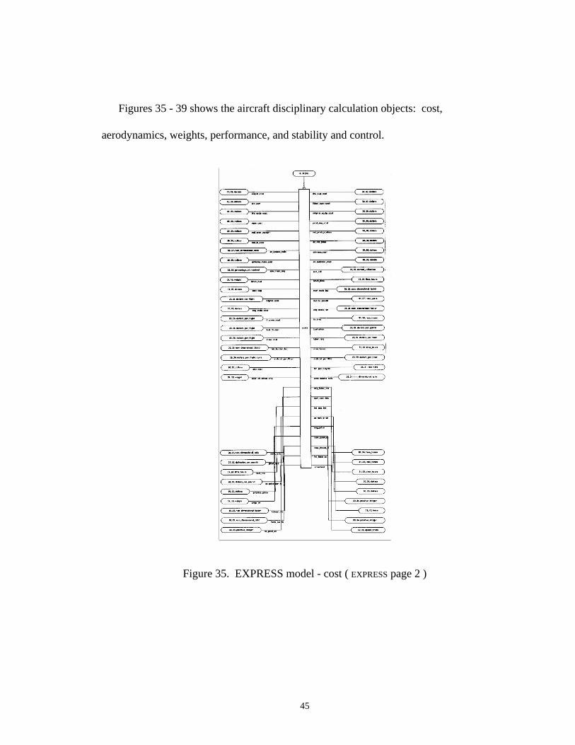
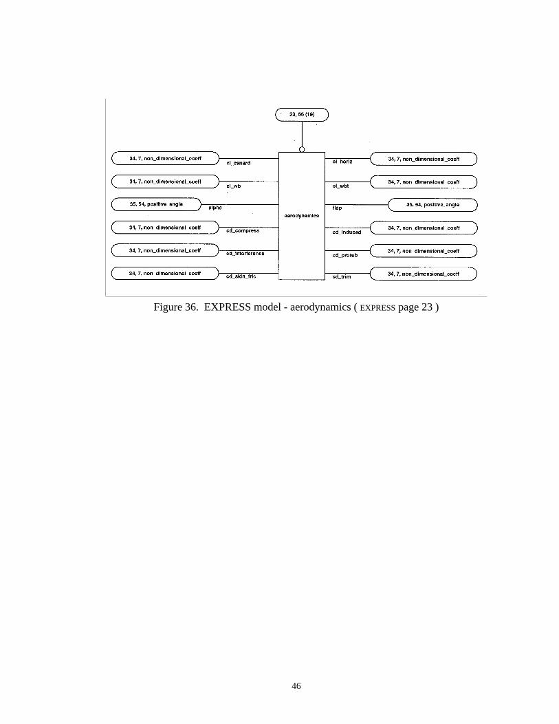
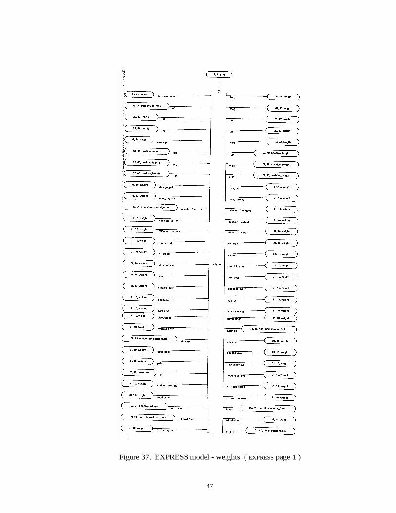
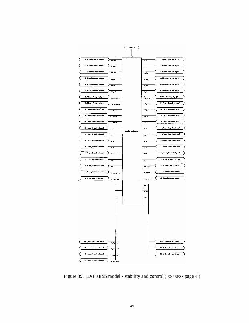
Figures 35 - 39 shows the aircraft disciplinary calculation objects: cost,
aerodynamics, weights, performance, and stability and control.
Figure 35. EXPRESS model - cost ( EXPRESS page 2 )
46
Figure 36. EXPRESS model - aerodynamics ( EXPRESS page 23 )
47
Figure 37. EXPRESS model - weights ( EXPRESS page 1 )
48
Figure 38. EXPRESS model - performance ( EXPRESS page 5 )
49
Figure 39. EXPRESS model - stability and control ( EXPRESS page 4 )

50
Implementation of Database
Implementation of the database model can be on any of the available object-oriented
database management systems or object-oriented database programming languages such
as Objectivity/DB, ONTOS, ObjectStore, VERSANT, and GemStone.
51
CHAPTER V
DATABASE PERFORMANCE METRICS
Benchmarks
Little work has been done on performance in the field of object data management,
despite its importance to most applications.15,16 Moreover, there seems to be even less
research in the area of performance comparisons between relational and object-oriented
DBMSs. One difficulty lies in the understanding of what constitutes performance? In his
book, R. G. G. Cattell discusses two kinds of DBMS performance issues, model-based
and architecture-based.
Model-based: In some cases, performance is limited by the data model, regardlessof how good the implementation. For example, relational-model implementationshave an impedance mismatch between programming and query language, forcingan application to represent a list (such as the chapters of a book) as a table, and tocopy the data wholesale from the table to a list in the programming language atruntime in order to manipulate the elements efficiently.
Architecture-based: ... the implementation of specific ODMS features can havemajor performance implications. In some cases, the implementation choices fortwo particular features, such as concurrency control and remote databases, caninteract favorably or very badly for overall speed. Thus, it is important toconsider the overall view.14
Application speed is still considered one of the most important performance metrics when
comparing DBMSs. Cattell and Skeen developed the OO1 (Object Operations, Version
1) benchmark to address some of these performance issues. The OO1 benchmark is
52
intended as a generic measure of ODMS performance. It was designed to approximate
database needs of CAD, CASE, and similar applications. A simple database of parts is
used with a many-to-many connection relationship between the parts. Three kinds of
operations were performed on the parts and connections: lookup, traversal, and insert.17
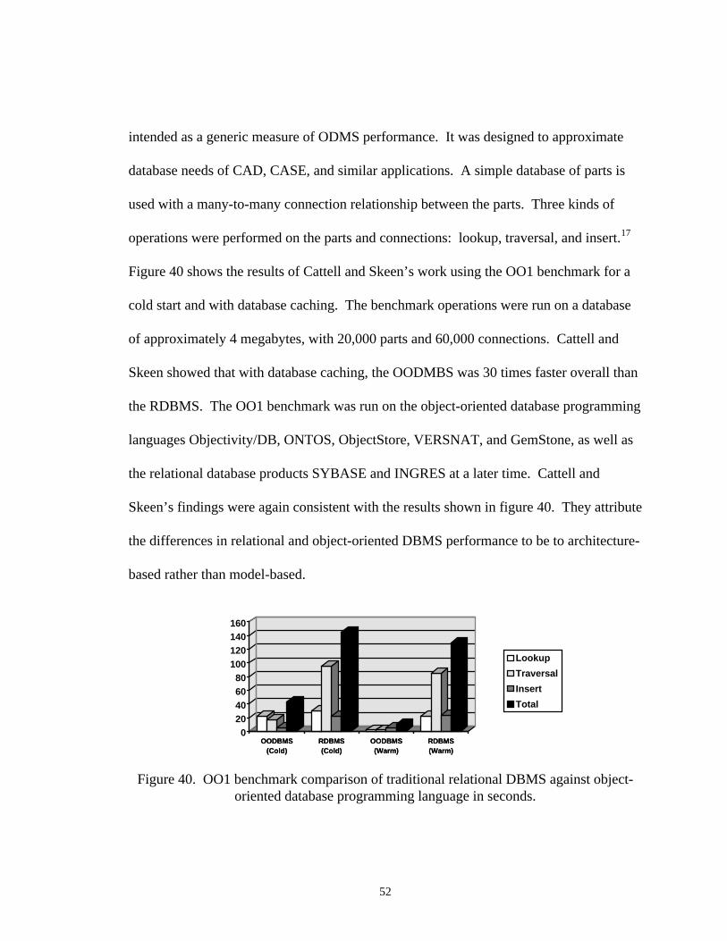
Figure 40 shows the results of Cattell and Skeen’s work using the OO1 benchmark for a
cold start and with database caching. The benchmark operations were run on a database
of approximately 4 megabytes, with 20,000 parts and 60,000 connections. Cattell and
Skeen showed that with database caching, the OODMBS was 30 times faster overall than
the RDBMS. The OO1 benchmark was run on the object-oriented database programming
languages Objectivity/DB, ONTOS, ObjectStore, VERSNAT, and GemStone, as well as
the relational database products SYBASE and INGRES at a later time. Cattell and
Skeen’s findings were again consistent with the results shown in figure 40. They attribute
the differences in relational and object-oriented DBMS performance to be to architecture-
based rather than model-based.
OODBMS(Cold)
RDBMS(Cold)
OODBMS(Warm)
RDBMS(Warm)
020406080
100120140160
OODBMS(Cold)
RDBMS(Cold)
OODBMS(Warm)
RDBMS(Warm)
Lookup
Traversal
Insert
Total
Figure 40. OO1 benchmark comparison of traditional relational DBMS against object-oriented database programming language in seconds.
53
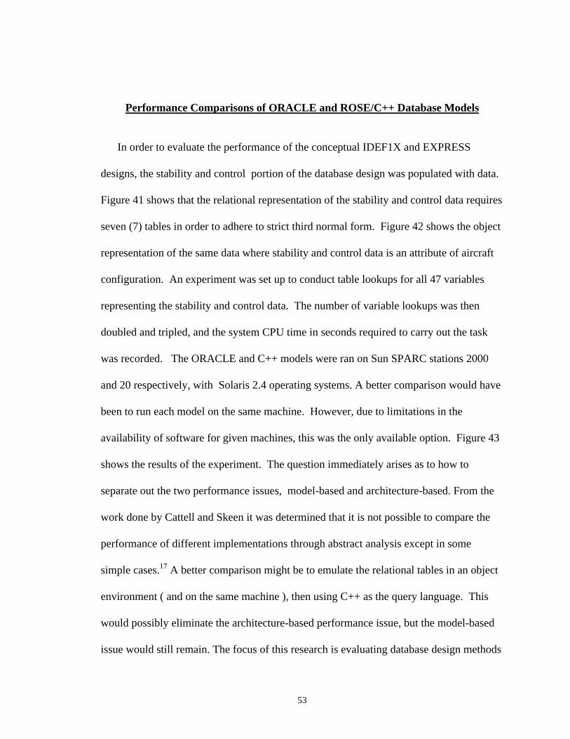
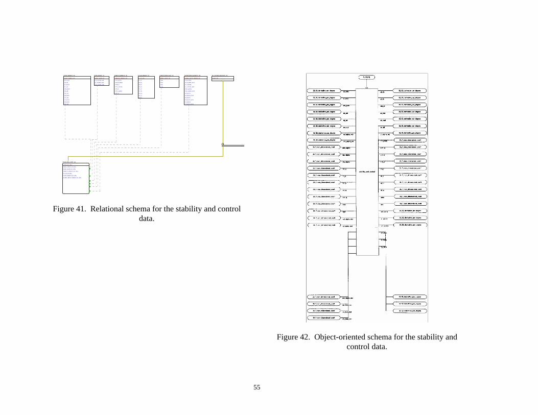
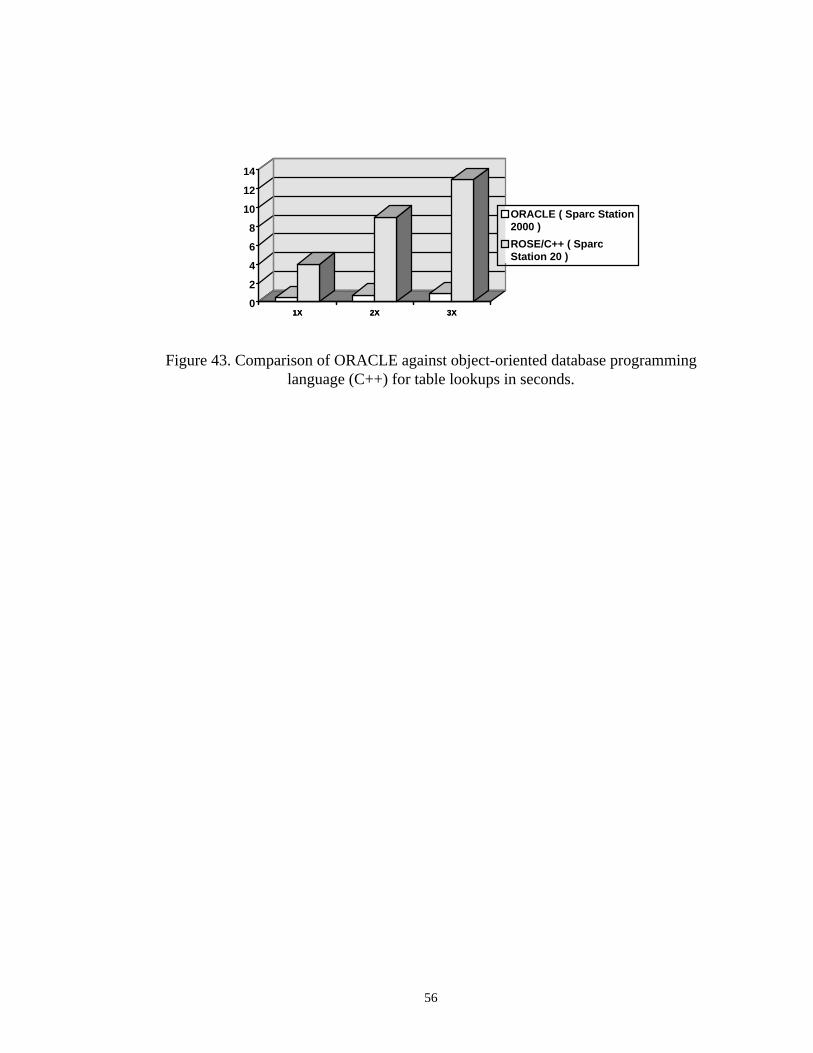
Performance Comparisons of ORACLE and ROSE/C++ Database Models
In order to evaluate the performance of the conceptual IDEF1X and EXPRESS
designs, the stability and control portion of the database design was populated with data.
Figure 41 shows that the relational representation of the stability and control data requires
seven (7) tables in order to adhere to strict third normal form. Figure 42 shows the object
representation of the same data where stability and control data is an attribute of aircraft
configuration. An experiment was set up to conduct table lookups for all 47 variables
representing the stability and control data. The number of variable lookups was then
doubled and tripled, and the system CPU time in seconds required to carry out the task
was recorded. The ORACLE and C++ models were ran on Sun SPARC stations 2000
and 20 respectively, with Solaris 2.4 operating systems. A better comparison would have
been to run each model on the same machine. However, due to limitations in the
availability of software for given machines, this was the only available option. Figure 43
shows the results of the experiment. The question immediately arises as to how to
separate out the two performance issues, model-based and architecture-based. From the
work done by Cattell and Skeen it was determined that it is not possible to compare the
performance of different implementations through abstract analysis except in some
simple cases.17 A better comparison might be to emulate the relational tables in an object
environment ( and on the same machine ), then using C++ as the query language. This
would possibly eliminate the architecture-based performance issue, but the model-based
issue would still remain. The focus of this research is evaluating database design methods

54
and how these methods are impacted by an evolving database design. The conclusion is
that for this domain ( i.e. aircraft conceptual design ), the measure of performance that is
deemed most important is how the methodology performs in the environment in which it
was designed. It would be quite unnatural to model objects like relational tables in order
to provide a more neutral ground from which to evaluate performance. The bottom line is
that the aircraft designer is interested in how easy it is to introduce changes to a data
schema and implement those changes.
55
CONT_DERIVS / 29
CONT_DERIVS_ID
CD_ELEV
CD_IH
CL_ELEV
CL_IH
CM_ELEV
CM_IH
CN_AIL
CR_RUD
CY_AIL
CY_RUD
CN_RUD
CR_AIL
WING_BODY / 31
WING_BODY_ID
CD_ALPHA_WB
CL_ALPHA_WB
CM_ALPHA_WB
THRUST_DERIVS / 30
THRUST_DERIVS_ID
CNT_BETA
CTM_ALPHA
CTM_U
CTX_ALPHA
CTX_U
CTZ_ALPHA
CTZ_U
P_Q_R_DERIVS / 27
P_Q_R_ID
CN_P
CN_R
CR_P
CR_R
CY_P
CY_R
CD_Q
CL_Q
CM_Q
COEFF_ZERO_AOA / 32
ZERO_COEFF_ID
CMO
CNO
CRO
CYO
ALPHA_BETA_DE RIVS / 28
ALPHA_BETA_DERIVS_ID
CD_ALPHA
CD_ALPHA_DOT
CL_ALPHA
CL_ALPHA_DOT
CM_ALPHA
CM_ALPHA_DOT
CN_BETA
CN_BETA_DOT
CR_BETA
CR_BETA_DOT
CY_BETA
CY_BETA_DOT
AC_CONFIGURATION / 10
CONF_NO
STAB_AND_CONT / 20
CONF_NO (FK)
ZERO_COEFF_ID (FK)
WING_BODY_ID (FK)
P_Q_R_ID (FK)
CONT_DERIVS_ID (FK)
THRUST_DERIVS_ID (FK)
ALPHA_BETA_DERIVS_ID (FK)
Figure 41. Relational schema for the stability and controldata.
Figure 42. Object-oriented schema for the stability andcontrol data.
56
1X 2X 3X0
2
4
6
8
10
12
14
1X 2X 3X
ORACLE ( Sparc Station2000 )
ROSE/C++ ( SparcStation 20 )
Figure 43. Comparison of ORACLE against object-oriented database programminglanguage (C++) for table lookups in seconds.
57
CHAPTER VI
DESIGN COMPARISONS
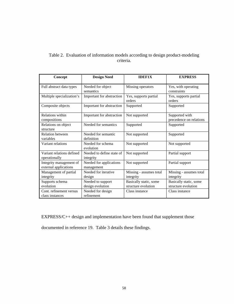
Evaluation of IDEF1X and EXPRESS (General)
Eastman and Fereshetian have developed an excellent set of design product-modeling
criteria. Table 2 shows this criteria for the IDEF1X and EXPRESS data models.
Eastman and Fereshetian found that IDEF1X lacks adequate support for object-oriented
concepts and does not address operator semantics provided by abstract data types of
methods. EXPRESS provides strong capabilities for defining the structures often
developed in object-oriented databases. Both IDEF1X and EXPRESS fail to reflect the
dynamic and evolutionary nature of design, because of the varied sequence of
applications and the possibly dynamic definition of the database schema as the design
proceeds. The IDEF1X and EXPRESS models appear to address more the
manufacturing end of the product development process, where the issues of change are
less important.19 The domain for this work was derived from the structure and function of
walls.
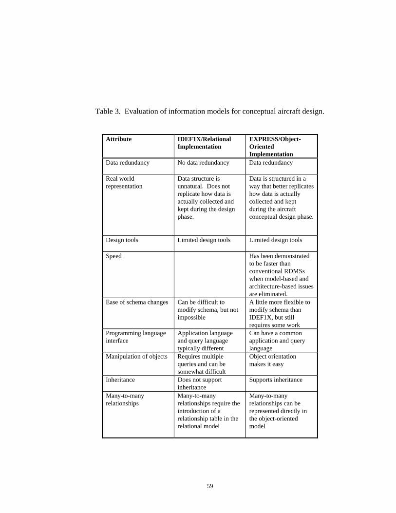
Evaluation of IDEF1X and EXPRESS (Specific)
Database designs have been generated using both the IDEF1X and EXPRESS data
models. Through this work certain benefits/detriments of the IDEF1X/Relational and
58
Table 2. Evaluation of information models according to design product-modelingcriteria.
Concept Design Need IDEF1X EXPRESS
Full abstract data types Needed for objectsemantics
Missing operators Yes, with operatingconstraints
Multiple specialization’s Important for abstraction Yes, supports partialorders
Yes, supports partialorders
Composite objects Important for abstraction Supported Supported
Relations withincompositions
Important for abstraction Not supported Supported withprecedence on relations
Relations on objectstructure
Needed for semantics Supported Supported
Relation betweenvariables
Needed for semanticdefinition
Not supported Supported
Variant relations Needed for schemaevolution
Not supported Not supported
Variant relations definedoperationally
Needed to define state ofintegrity
Not supported Partial support
Integrity management ofexternal applications
Needed for applicationsmanagement
Not supported Partial support
Management of partialintegrity
Needed for iterativedesign
Missing - assumes totalintegrity
Missing - assumes totalintegrity
Supports schemaevolution
Needed to supportdesign evolution
Basically static, somestructure evolution
Basically static, somestructure evolution
Cont. refinement versusclass instances
Needed for designrefinement
Class instance Class instance
EXPRESS/C++ design and implementation have been found that supplement those
documented in reference 19. Table 3 details these findings.
59
Table 3. Evaluation of information models for conceptual aircraft design.
Attribute IDEF1X/RelationalImplementation
EXPRESS/Object-OrientedImplementation
Data redundancy No data redundancy Data redundancy
Real worldrepresentation
Data structure isunnatural. Does notreplicate how data isactually collected andkept during the designphase.
Data is structured in away that better replicateshow data is actuallycollected and keptduring the aircraftconceptual design phase.
Design tools Limited design tools Limited design tools
Speed Has been demonstratedto be faster thanconventional RDMSswhen model-based andarchitecture-based issuesare eliminated.
Ease of schema changes Can be difficult tomodify schema, but notimpossible
A little more flexible tomodify schema thanIDEF1X, but stillrequires some work
Programming languageinterface
Application languageand query languagetypically different
Can have a commonapplication and querylanguage
Manipulation of objects Requires multiplequeries and can besomewhat difficult
Object orientationmakes it easy
Inheritance Does not supportinheritance
Supports inheritance
Many-to-manyrelationships
Many-to-manyrelationships require theintroduction of arelationship table in therelational model
Many-to-manyrelationships can berepresented directly inthe object-orientedmodel

60
In nearly all applications, it is important to be able to modify a schema with minimum
impact on exiting applications. This can be even more important in design applications,
because the user as well as the application programmer may modify the schema ( for
example, to define new types of design components or design constraints). Current
DBMSs do not provide good facilities to migrate data to new schemas.14 Typically, the
application language and query language are different in RDBMSs requiring pre-
compilers. If the C++ programming language is chosen, then the application and query
language can be common. The OODBMSs allows for an object type to have all of the
attributes of an existing object whereas RDBMSs do not support inheritance.
Binary many-to-many relationships can be represented directly in the object-oriented
model through two list-valued attributes, but they demand the introduction of a
relationship table in the relational model (if the database is to be in first normal form).14

61
CHAPTER VII
CONCLUSIONS
New aircraft designs have become increasingly advanced and complex. Advances
made in the scientific and engineering technologies have resulted in nontraditional
aircraft designs using high technology materials. Multidisciplinary Design Optimization
(MDO) will take advantage of an evolving high speed computing environment and will
be a critical component in the design of the HSCT. A major emphasis is also being
placed on using concepts such as Integrated Product and Process Development (IPPD)
and Concurrent Engineering (CE) as a means of improving the product development
process.
The multidisciplinary design effort of the HSCT will require large amounts of data
exchange. The advancements made in computing technology will further this enormity of
data. It is critical that a data management system be in place very early in the design
process, preferably before the process begins. The design of a data management system
should command the same level of priority as that given to other disciplines involved in
the process. Moreover, customers have been independently developing data management
structures for use internally in order to streamline processes and costs. In today's
environment, the customer wants to be directly involved in the design process. This has
62
certainly been proven with the design of the Boeing 777. In order to be responsive to
customer requirements, a data management system must be in place.
This research has focused on the impact of data modeling and database
implementation methods in order to gain a better understanding of how efficient data
management can optimize the aircraft design process. This research has included the
development of a formal process model for the conceptual aircraft design sequence. The
author has been involved in numerous conceptual studies over the last ten years with two
major airframe companies. Although each company was very active in the conceptual
design process, there seemed to be a lack of process formality. Part of this research has
been to identify a common process in order to ascertain what the data requirements are
for the process.
Two database design approaches have been taken. An IDEF1X approach with a
relational implementation and an EXPRESS approach with a C++ programming language
implementation. In the development of these database designs it became apparent that
current database design approaches are typically limited to the detailed design phase
where the data organization is fixed. A major problem is the development of a database
design approach to support the conceptual design of complex engineering products where
the database organization is evolving.
63
The popularity of the relational data model is partly due to its simplicity. It is easy to
understand because data is structured in tables, a concept familiar to almost everyone.
The maturity level of the RDBMs also makes it quite attractive. It provides a very
powerful query language and very little programming is required for implementation.
However, the relational model is best suited for the data retrieval and manipulation of
business application requirements and not engineering applications. In modeling the data
required for conceptual design, if third normal form is strictly enforced, the organization
of the data is very unnatural. Unnatural here means that the data structure is very
unrepresentative of how that data exists in the physical world.
The object-oriented representation of conceptual design data does a better job at
providing a more realistic or natural data structure than the relational approach. Cattell
states that the context of object data management are in the three areas of software
engineering, mechanical and electrical engineering, and documents.14 Design tools such
as CAD and CAE have database systems embedded inside them which are not typically
accessible by the user. The problem arises when the user is faced with a variety of
application all with incompatible data representations.
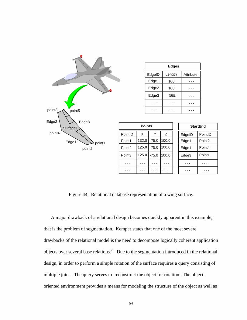
Consider the simplistic wing example shown in figure 44. In order to describe a single
surface with relational tables would require a minimum of the three tables shown. An
edge is described by two points and five edges describe the single surface denoted as
Surface 1.
64
Edge1
Edge2 Edge3
point1
point3
point2
Edges
EdgeID Length Attribute
Edge1
Edge2
Edge3
100.
100.
350.
. . .
. . .
. . .
. . .
. . .
. . .
. . .
. . .
. . .
Points
PointID X
Point1
Point2
Point3
. . .
. . .
. . .
. . .
Y Z
132.0 75.0 100.0
125.0
125.0
75.0
-75.0
100.0
100.0
. . . . . .
. . . . . .
point4
point5
StartEnd
EdgeID PointID
. . .
. . .
. . .
. . .
Edge1
Edge1
Point2
Point4
Edge3 Point1
Surface1
Figure 44. Relational database representation of a wing surface.
A major drawback of a relational design becomes quickly apparent in this example,
that is the problem of segmentation. Kemper states that one of the most severe
drawbacks of the relational model is the need to decompose logically coherent application
objects over several base relations.20 Due to the segmentation introduced in the relational
design, in order to perform a simple rotation of the surface requires a query consisting of
multiple joins. The query serves to reconstruct the object for rotation. The object-
oriented environment provides a means for modeling the structure of the object as well as

65
its behavior. It is this function that makes the object-oriented approach to data modeling
very appealing for engineering applications.
66
CHAPTER VIII
RECOMMENDATIONS
Conceptually, both the IDEF1X/ORACLE and EXPRESS/Object-oriented
programming language approaches fall short of providing the user with the ease of
schema changes. However, less work is required when using the EXPRESS/Object-
oriented programming language methodology when making schema changes. This is a
very desirable feature in the domain of conceptual aircraft design. It is important for the
user to be able to modify a schema with minimum impact on existing applications.14 Of
the two approaches researched, the EXPRESS/Object-oriented programming language
offers the best solution at the present time. The reasons for this choice are: (1) more
commonality with the physical world, (2) commonality in application and query
language, (3) the increased activity and support for STEP protocols, which are developed
using EXPRESS, (4) relative ease in the manipulation of objects, (5) OODBMSs
currently have the best chance for providing a solution where applications and CAD
models share a common database, and (6) OODBMSs are still in the infancy stage when
compared to RDBMs. The power of the RDBMS is partly derived from the RDBMS’s
maturity level. Where RDBMS capabilities are becoming more saturated over time, the
67
OODBMS capabilities are just beginning to be exploited, and this will continue to
increase over time.
Figure 45 is a recommended database design strategy. The ultimate goal would be to
develop an application protocol within STEP. With the numerous applications that have
been developed already, as well as those currently in development, there does not exist a
project for developing an application protocol for core conceptual aircraft design. The
author realizes that the conceptual design phase is highly dependent upon the design in
question, however, a baseline standardization would definitely serve as a design
optimization tool. This would be extremely helpful in the situation where there are a
variety of different companies working on the same design and the need for sharing data
exists. The steps proposed for database design are:
1. Development of a process model
2. Development of a data dictionary
3. Development of a data schema
4. Creation of populated objects
5. Object-oriented programming language for data manipulation
6. Development of a STEP application protocol
It is also suggested that the data schema should serve as a template to help optimize
the design process early in the data management development stages. One of the
68
impediments to successful database design implementation is overcoming the existing
cultural barriers within a company. Using the data schema as a template prior to any
database implementation would at least eliminate some of the data redundancy problems
that are so common today. Cultural barriers are built up over time. Overcoming some of
the data management problems will take time as well. This first small step could serve as
the first increment toward breaking down some these cultural barriers.
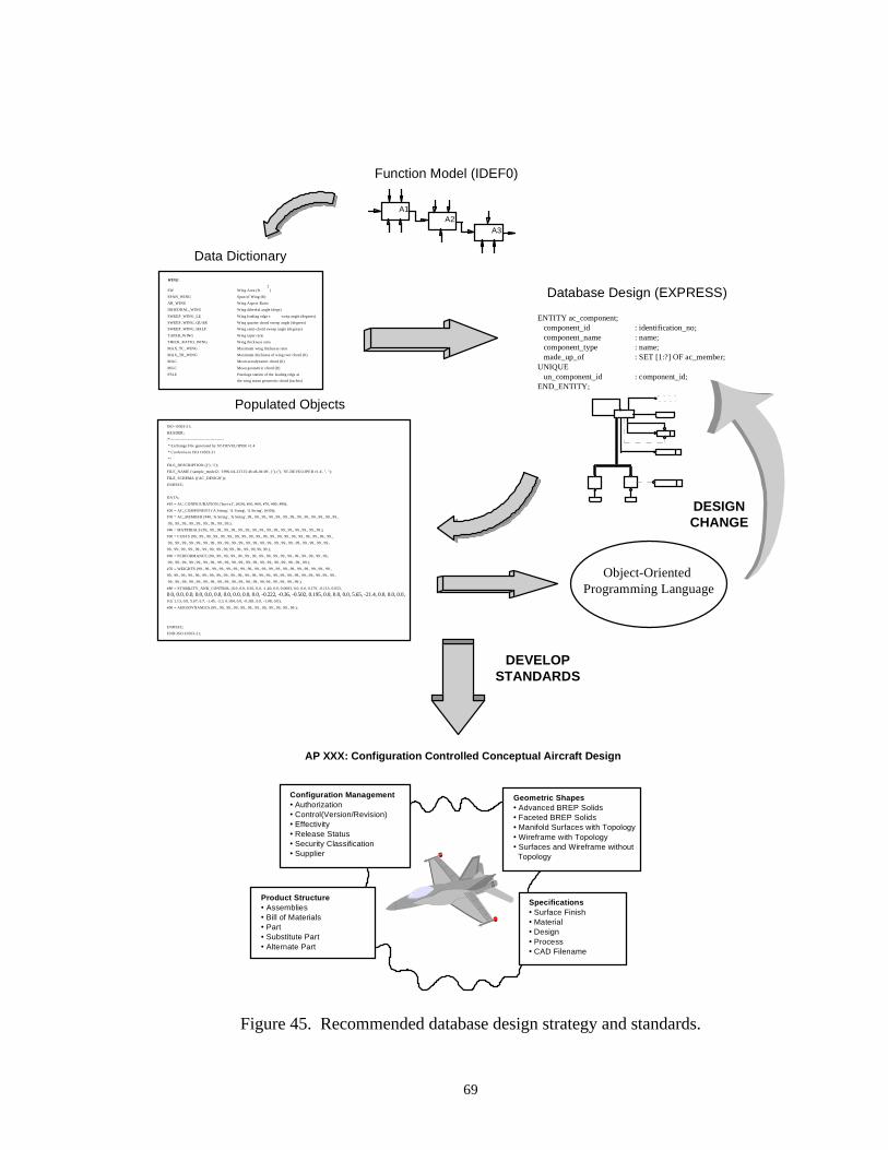
69
A1A2
A3
Function Model (IDEF0)
WING
SW
SPAN_WING
AR_WING
DIHEDRAL_WING
SWEEP_WING_LE
SWEEP_WING_QUAR
SWEEP_WING_HALF
TAPER_WING
THICK_RATIO_WING
MAX_TC_WING
MAX_TR_WING
MAC
MGC
FSLE
Wing Area (ft2
)
Span of Wing (ft)
Wing Aspect Ratio
Wing dihedral angle (degs)
Wing leading edge s weep angle (degrees)
Wing quarter chord sweep angle (degrees)
Wing semi-chord sweep angle (degrees)
Wing taper ratio
Wing thickness ratio
Maximum wing thickness ratio
Maximum thickness of wing root chord (ft)
Mean aerodynamic chord (ft)
Mean geometric chord (ft)
Fuselage station of the leading edge at
the wing mean geometric chord (inches)
Data Dictionary
Database Design (EXPRESS)
ENTITY ac_component; component_id : identification_no; component_name : name; component_type : name; made_up_of : SET [1:?] OF ac_member;UNIQUE un_component_id : component_id;END_ENTITY;
AP XXX: Configuration Controlled Conceptual Aircraft Design
Configuration Management• Authorization• Control(Version/Revision)• Effectivity• Release Status• Security Classification• Supplier
Geometric Shapes• Advanced BREP Solids• Faceted BREP Solids• Manifold Surfaces with Topology• Wireframe with Topology• Surfaces and Wireframe without Topology
Specifications• Surface Finish• Material• Design• Process• CAD Filename
Product Structure• Assemblies• Bill of Materials• Part• Substitute Part• Alternate Part
0.0, 0.0, 0.0, 0.0, 0.0, 0.0, 0.0, 0.0, 0.0, 0.0, -0.222, -0.36, -0.502, 0.195, 0.0, 0.0, 0.0, 5.65, -21.4, 0.0, 0.0, 0.0,
ISO-10303-21;
HEADER;
/*----------------------------------------
* Exchange File generated by ST-DEVELOPER v1.4
* Conforms to ISO 10303-21
*/
FILE_DESCRIPTION ((''), '1');
FILE_NAME ('sample_model2', '1996-04-23T15:46:46-04:00', (''), (''), 'ST-DEVELOPER v1.4', '', '');
FILE_SCHEMA (('AC_DESIGN'));
ENDSEC;
DATA;
#10 = AC_CONFIGURATION ('hsct-x1', (#20), #50, #60, #70, #80, #90);
#20 = AC_COMPONENT ('A String', 'A String', 'A String', (#30));
#30 = AC_MEMBER (#40, 'A String', 'A String', 99., 99., 99., 99., 99., 99., 99., 99., 99., 99., 99., 99., 99.,
99., 99., 99., 99., 99., 99., 99., 99., 99.);
#40 = MATERIALS (99., 99., 99., 99., 99., 99., 99., 99., 99., 99., 99., 99., 99., 99., 99., 99., 99.);
#50 = COSTS (99., 99., 99., 99., 99., 99., 99., 99., 99., 99., 99., 99., 99., 99., 99., 99., 99., 99., 99., 99.,
99., 99., 99., 99., 99., 99., 99., 99., 99., 99., 99., 99., 99., 99., 99., 99., 99., 99., 99., 99., 99., 99., 99.,
99., 99., 99., 99., 99., 99., 99., 99., 99, 99., 99., 99., 99, 99, 99.);
#60 = PERFORMANCE (99., 99., 99., 99., 99., 99., 99., 99., 99., 99., 99., 99., 99., 99., 99., 99., 99.,
99., 99., 99., 99., 99., 99., 99., 99., 99., 99., 99., 99., 99., 99., 99., 99., 99., 99., 99., 99.);
#70 = WEIGHTS (99., 99., 99., 99., 99., 99., 99., 99., 99., 99., 99., 99., 99., 99., 99., 99., 99., 99., 99.,
99., 99., 99., 99., 99., 99., 99., 99., 99., 99., 99., 99., 99., 99., 99., 99., 99., 99., 99., 99., 99., 99., 99., 99.,
99., 99., 99., 99., 99., 99., 99., 99., 99., 99., 99., 99., 99., 99, 99., 99., 99., 99., 99.);
#80 = STABILITY_AND_CONTROL (0.0, 0.0, 0.36, 0.0, -1.40, 0.0, 0.0083, 0.0, 0.0, 0.179, -0.113, 0.053,
0.0, 1.13, 0.0, 5.67, 6.7, -1.45, -3.3, 0.184, 0.0, -0.281, 0.0, -1.08, 0.0);
#90 = AERODYNAMICS (99., 99., 99., 99., 99., 99., 99., 99., 99., 99., 99., 99.);
ENDSEC;
END-ISO-10303-21;
Populated Objects
Object-Oriented Programming Language
DESIGNCHANGE
DEVELOPSTANDARDS
Figure 45. Recommended database design strategy and standards.
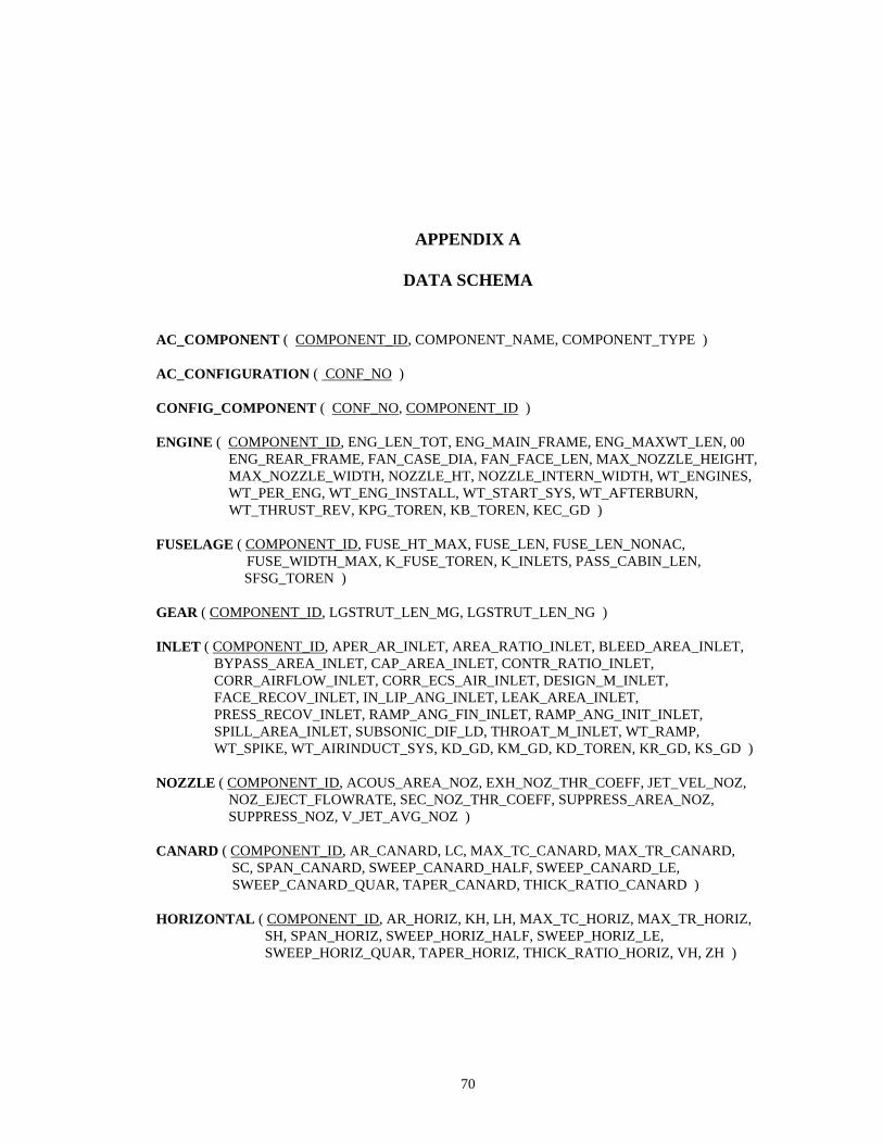
70
APPENDIX A
DATA SCHEMA
AC_COMPONENT ( COMPONENT_ID, COMPONENT_NAME, COMPONENT_TYPE )
AC_CONFIGURATION ( CONF_NO )
CONFIG_COMPONENT ( CONF_NO, COMPONENT_ID )
ENGINE ( COMPONENT_ID, ENG_LEN_TOT, ENG_MAIN_FRAME, ENG_MAXWT_LEN, 00 ENG_REAR_FRAME, FAN_CASE_DIA, FAN_FACE_LEN, MAX_NOZZLE_HEIGHT, MAX_NOZZLE_WIDTH, NOZZLE_HT, NOZZLE_INTERN_WIDTH, WT_ENGINES, WT_PER_ENG, WT_ENG_INSTALL, WT_START_SYS, WT_AFTERBURN, WT_THRUST_REV, KPG_TOREN, KB_TOREN, KEC_GD )
FUSELAGE ( COMPONENT_ID, FUSE_HT_MAX, FUSE_LEN, FUSE_LEN_NONAC, FUSE_WIDTH_MAX, K_FUSE_TOREN, K_INLETS, PASS_CABIN_LEN,
SFSG_TOREN )
GEAR ( COMPONENT_ID, LGSTRUT_LEN_MG, LGSTRUT_LEN_NG )
INLET ( COMPONENT_ID, APER_AR_INLET, AREA_RATIO_INLET, BLEED_AREA_INLET, BYPASS_AREA_INLET, CAP_AREA_INLET, CONTR_RATIO_INLET, CORR_AIRFLOW_INLET, CORR_ECS_AIR_INLET, DESIGN_M_INLET, FACE_RECOV_INLET, IN_LIP_ANG_INLET, LEAK_AREA_INLET, PRESS_RECOV_INLET, RAMP_ANG_FIN_INLET, RAMP_ANG_INIT_INLET, SPILL_AREA_INLET, SUBSONIC_DIF_LD, THROAT_M_INLET, WT_RAMP, WT_SPIKE, WT_AIRINDUCT_SYS, KD_GD, KM_GD, KD_TOREN, KR_GD, KS_GD )
NOZZLE ( COMPONENT_ID, ACOUS_AREA_NOZ, EXH_NOZ_THR_COEFF, JET_VEL_NOZ, NOZ_EJECT_FLOWRATE, SEC_NOZ_THR_COEFF, SUPPRESS_AREA_NOZ, SUPPRESS_NOZ, V_JET_AVG_NOZ )
CANARD ( COMPONENT_ID, AR_CANARD, LC, MAX_TC_CANARD, MAX_TR_CANARD, SC, SPAN_CANARD, SWEEP_CANARD_HALF, SWEEP_CANARD_LE, SWEEP_CANARD_QUAR, TAPER_CANARD, THICK_RATIO_CANARD )
HORIZONTAL ( COMPONENT_ID, AR_HORIZ, KH, LH, MAX_TC_HORIZ, MAX_TR_HORIZ, SH, SPAN_HORIZ, SWEEP_HORIZ_HALF, SWEEP_HORIZ_LE, SWEEP_HORIZ_QUAR, TAPER_HORIZ, THICK_RATIO_HORIZ, VH, ZH )
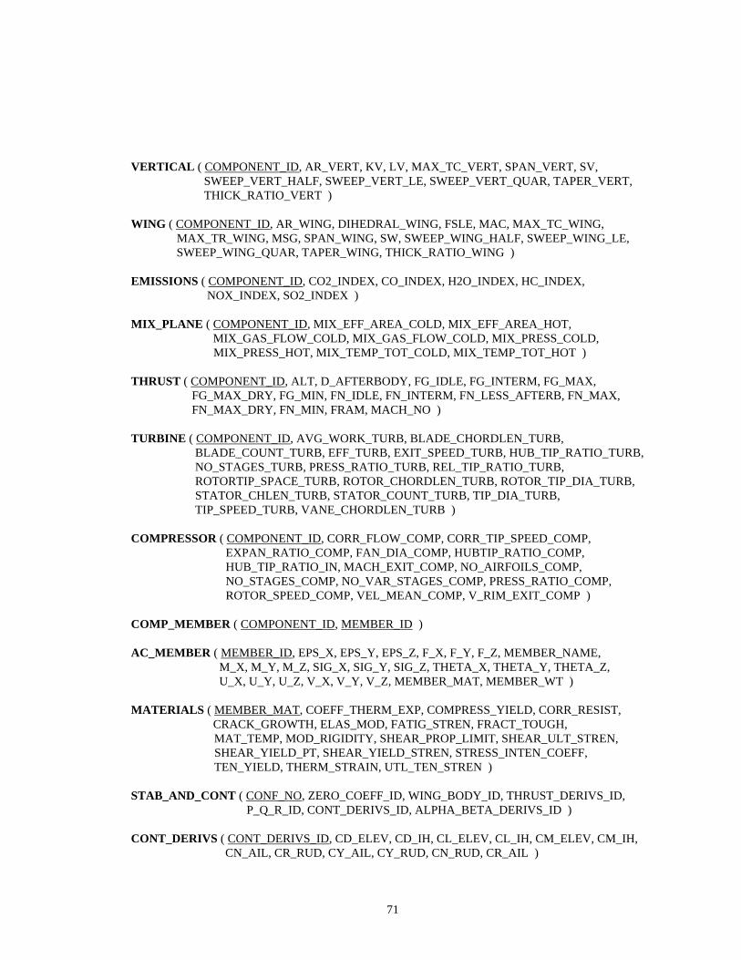
71
VERTICAL ( COMPONENT_ID, AR_VERT, KV, LV, MAX_TC_VERT, SPAN_VERT, SV, SWEEP_VERT_HALF, SWEEP_VERT_LE, SWEEP_VERT_QUAR, TAPER_VERT, THICK_RATIO_VERT )
WING ( COMPONENT_ID, AR_WING, DIHEDRAL_WING, FSLE, MAC, MAX_TC_WING, MAX_TR_WING, MSG, SPAN_WING, SW, SWEEP_WING_HALF, SWEEP_WING_LE, SWEEP_WING_QUAR, TAPER_WING, THICK_RATIO_WING )
EMISSIONS ( COMPONENT_ID, CO2_INDEX, CO_INDEX, H2O_INDEX, HC_INDEX, NOX_INDEX, SO2_INDEX )
MIX_PLANE ( COMPONENT_ID, MIX_EFF_AREA_COLD, MIX_EFF_AREA_HOT, MIX_GAS_FLOW_COLD, MIX_GAS_FLOW_COLD, MIX_PRESS_COLD, MIX_PRESS_HOT, MIX_TEMP_TOT_COLD, MIX_TEMP_TOT_HOT )
THRUST ( COMPONENT_ID, ALT, D_AFTERBODY, FG_IDLE, FG_INTERM, FG_MAX, FG_MAX_DRY, FG_MIN, FN_IDLE, FN_INTERM, FN_LESS_AFTERB, FN_MAX, FN_MAX_DRY, FN_MIN, FRAM, MACH_NO )
TURBINE ( COMPONENT_ID, AVG_WORK_TURB, BLADE_CHORDLEN_TURB, BLADE_COUNT_TURB, EFF_TURB, EXIT_SPEED_TURB, HUB_TIP_RATIO_TURB, NO_STAGES_TURB, PRESS_RATIO_TURB, REL_TIP_RATIO_TURB, ROTORTIP_SPACE_TURB, ROTOR_CHORDLEN_TURB, ROTOR_TIP_DIA_TURB, STATOR_CHLEN_TURB, STATOR_COUNT_TURB, TIP_DIA_TURB, TIP_SPEED_TURB, VANE_CHORDLEN_TURB )
COMPRESSOR ( COMPONENT_ID, CORR_FLOW_COMP, CORR_TIP_SPEED_COMP, EXPAN_RATIO_COMP, FAN_DIA_COMP, HUBTIP_RATIO_COMP, HUB_TIP_RATIO_IN, MACH_EXIT_COMP, NO_AIRFOILS_COMP, NO_STAGES_COMP, NO_VAR_STAGES_COMP, PRESS_RATIO_COMP, ROTOR_SPEED_COMP, VEL_MEAN_COMP, V_RIM_EXIT_COMP )
COMP_MEMBER ( COMPONENT_ID, MEMBER_ID )
AC_MEMBER ( MEMBER_ID, EPS_X, EPS_Y, EPS_Z, F_X, F_Y, F_Z, MEMBER_NAME, M_X, M_Y, M_Z, SIG_X, SIG_Y, SIG_Z, THETA_X, THETA_Y, THETA_Z, U_X, U_Y, U_Z, V_X, V_Y, V_Z, MEMBER_MAT, MEMBER_WT )
MATERIALS ( MEMBER_MAT, COEFF_THERM_EXP, COMPRESS_YIELD, CORR_RESIST, CRACK_GROWTH, ELAS_MOD, FATIG_STREN, FRACT_TOUGH,
MAT_TEMP, MOD_RIGIDITY, SHEAR_PROP_LIMIT, SHEAR_ULT_STREN, SHEAR_YIELD_PT, SHEAR_YIELD_STREN, STRESS_INTEN_COEFF, TEN_YIELD, THERM_STRAIN, UTL_TEN_STREN )
STAB_AND_CONT ( CONF_NO, ZERO_COEFF_ID, WING_BODY_ID, THRUST_DERIVS_ID, P_Q_R_ID, CONT_DERIVS_ID, ALPHA_BETA_DERIVS_ID )
CONT_DERIVS ( CONT_DERIVS_ID, CD_ELEV, CD_IH, CL_ELEV, CL_IH, CM_ELEV, CM_IH, CN_AIL, CR_RUD, CY_AIL, CY_RUD, CN_RUD, CR_AIL )
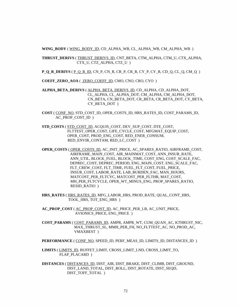
72
WING_BODY ( WING_BODY_ID, CD_ALPHA_WB, CL_ALPHA_WB, CM_ALPHA_WB )
THRUST_DERIVS ( THRUST_DERIVS_ID, CNT_BETA, CTM_ALPHA, CTM_U, CTX_ALPHA, CTX_U, CTZ_ALPHA, CTZ_U )
P_Q_R_DERIVS ( P_Q_R_ID, CN_P, CN_R, CR_P, CR_R, CY_P, CY_R, CD_Q, CL_Q, CM_Q )
COEFF_ZERO_AOA ( ZERO_COEFF_ID, CMO, CNO, CRO, CYO )
ALPHA_BETA_DERIVS ( ALPHA_BETA_DERIVS_ID, CD_ALPHA, CD_ALPHA_DOT, CL_ALPHA, CL_ALPHA_DOT, CM_ALPHA, CM_ALPHA_DOT, CN_BETA, CN_BETA_DOT, CR_BETA, CR_BETA_DOT, CY_BETA, CY_BETA_DOT )
COST ( CONF_NO, STD_COST_ID, OPER_COSTS_ID, HRS_RATES_ID, COST_PARAMS_ID, AC_PROP_COST_ID )
STD_COSTS ( STD_COST_ID, ACQUIS_COST, DEV_SUP_COST, DTE_COST, FLTTEST_OPER_COST, LIFE_CYCLE_COST, MFGMAT_EQUIP_COST, OPER_COST, PROD_ENG_COST, RED_ENER_CONSUM,
RED_ENVIR_CONTAM, RED_LC_COST )
OPER_COSTS ( OPER_COSTS_ID, AC_INIT_PRICE, AC_SPARES_RATIO, AIRFRAME_COST, AIRFRAME_MAIN_COST, AIR_MAINMAT_COST, ANN_INSUR_RATE, ANN_UTIL, BLOCK_FUEL, BLOCK_TIME, COST_ENG, COST_SCALE_FAC, DEPREC_COST, DEPREC_PERIOD, ENG_MAIN_COST, ENG_SCALE_FAC, FLT_CREW_COST, FLT_TIME, FUEL_FLT_COST, FUEL_PRICE,
INSUR_COST, LABOR_RATE, LAB_BURDEN_FAC, MAN_HOURS, MATCOST_PER_FLTCYC, MATCOST_PER_FLTHR, MAT_COST, MH_PER_FLTCYCLE, OPER_WT_MINUS_ENG, PROP_SPARES_RATIO, RESID_RATIO )
HRS_RATES ( HRS_RATES_ID, MFG_LABOR_HRS, PROD_RATE, QUAL_CONT_HRS, TOOL_HRS, TOT_ENG_HRS )
AC_PROP_COST ( AC_PROP_COST_ID, AC_PRICE_PER_LB, AC_UNIT_PRICE, AVIONICS_PRICE, ENG_PRICE )
COST_PARAMS ( COST_PARAMS_ID, AMPR, AMPR_WT, CUM_QUAN_AC, KTHRUST_NIC, MAX_THRUST_SL, MMH_PER_FH, NO_FLTTEST_AC, NO_PROD_AC, VMAXBEST )
PERFORMANCE ( CONF_NO, SPEED_ID, PERF_MEAS_ID, LIMITS_ID, DISTANCES_ID )
LIMITS ( LIMITS_ID, BUFFET_LIMIT, CROSS_LIMIT_LND, CROSS_LIMIT_TO, FLAP_PLACARD )
DISTANCES ( DISTANCES_ID, DIST_AIR, DIST_BRAKE, DIST_CLIMB, DIST_GROUND, DIST_LAND_TOTAL, DIST_ROLL, DIST_ROTATE, DIST_SEQD, DIST_TOFF_TOTAL )
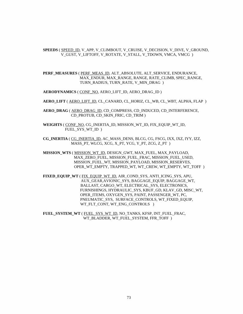
73
SPEEDS ( SPEED_ID, V_APP, V_CLIMBOUT, V_CRUISE, V_DECISION, V_DIVE, V_GROUND, V_GUST, V_LIFTOFF, V_ROTATE, V_STALL, V_TDOWN, VMCA, VMCG )
PERF_MEASURES ( PERF_MEAS_ID, ALT_ABSOLUTE, ALT_SERVICE, ENDURANCE, MAX_ENDUR, MAX_RANGE, RANGE, RATE_CLIMB, SPEC_RANGE, TURN_RADIUS, TURN_RATE, V_MIN_DRAG )
AERODYNAMICS ( CONF_NO, AERO_LIFT_ID, AERO_DRAG_ID )
AERO_LIFT ( AERO_LIFT_ID, CL_CANARD, CL_HORIZ, CL_WB, CL_WBT, ALPHA, FLAP )
AERO_DRAG ( AERO_DRAG_ID, CD_COMPRESS, CD_INDUCED, CD_INTERFERENCE, CD_PROTUB, CD_SKIN_FRIC, CD_TRIM )
WEIGHTS ( CONF_NO, CG_INERTIA_ID, MISSION_WT_ID, FIX_EQUIP_WT_ID, FUEL_SYS_WT_ID )
CG_INERTIA ( CG_INERTIA_ID, AC_MASS_DENS, BLCG, CG, FSCG, IXX, IXZ, IYY, IZZ, MASS_PT, WLCG, XCG, X_PT, YCG, Y_PT, ZCG, Z_PT )
MISSION_WTS ( MISSION_WT_ID, DESIGN_GWT, MAX_FUEL, MAX_PAYLOAD, MAX_ZERO_FUEL, MISSION_FUEL_FRAC, MISSION_FUEL_USED, MISSION_FUEL_WT, MISSION_PAYLOAD, MISSION_RESERVES, OPER_WT_EMPTY, TRAPPED_WT, WT_CREW, WT_EMPTY, WT_TOFF )
FIXED_EQUIP_WT ( FIX_EQUIP_WT_ID, AIR_COND_SYS, ANTI_ICING_SYS, APU, AUX_GEAR,AVIONIC_SYS, BAGGAGE_EQUIP, BAGGAGE_WT,
BALLAST, CARGO_WT, ELECTRICAL_SYS, ELECTRONICS, FURNISHINGS, HYDRAULIC_SYS, KBUF_GD, KLAV_GD, MISC_WT, OPER_ITEMS, OXYGEN_SYS, PAINT, PASSENGER_WT, PC, PNEUMATIC_SYS, SURFACE_CONTROLS, WT_FIXED_EQUIP, WT_FLT_CONT, WT_ENG_CONTROLS )
FUEL_SYSTEM_WT ( FUEL_SYS_WT_ID, NO_TANKS, KFSP, INT_FUEL_FRAC, WT_BLADDER, WT_FUEL_SYSTEM, FFR_TOFF )
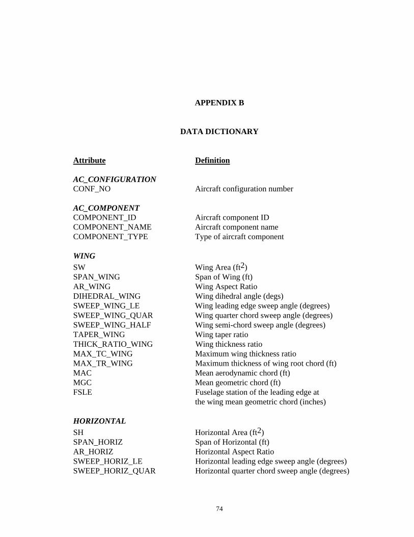
74
APPENDIX B
DATA DICTIONARY
Attribute Definition
AC_CONFIGURATIONCONF_NO Aircraft configuration number
AC_COMPONENTCOMPONENT_ID Aircraft component IDCOMPONENT_NAME Aircraft component nameCOMPONENT_TYPE Type of aircraft component
WINGSW Wing Area (ft2)SPAN_WING Span of Wing (ft)AR_WING Wing Aspect RatioDIHEDRAL_WING Wing dihedral angle (degs)SWEEP_WING_LE Wing leading edge sweep angle (degrees)SWEEP_WING_QUAR Wing quarter chord sweep angle (degrees)SWEEP_WING_HALF Wing semi-chord sweep angle (degrees)TAPER_WING Wing taper ratioTHICK_RATIO_WING Wing thickness ratioMAX_TC_WING Maximum wing thickness ratioMAX_TR_WING Maximum thickness of wing root chord (ft)MAC Mean aerodynamic chord (ft)MGC Mean geometric chord (ft)FSLE Fuselage station of the leading edge at
the wing mean geometric chord (inches)
HORIZONTALSH Horizontal Area (ft2)SPAN_HORIZ Span of Horizontal (ft)AR_HORIZ Horizontal Aspect RatioSWEEP_HORIZ_LE Horizontal leading edge sweep angle (degrees)SWEEP_HORIZ_QUAR Horizontal quarter chord sweep angle (degrees)
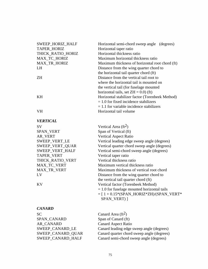
75
SWEEP_HORIZ_HALF Horizontal semi-chord sweep angle (degrees)TAPER_HORIZ Horizontal taper ratioTHICK_RATIO_HORIZ Horizontal thickness ratioMAX_TC_HORIZ Maximum horizontal thickness ratioMAX_TR_HORIZ Maximum thickness of horizontal root chord (ft)LH Distance from the wing quarter chord to
the horizontal tail quarter chord (ft)ZH Distance from the vertical tail root to
where the horizontal tail is mounted onthe vertical tail (for fuselage mountedhorizontal tails, set ZH = 0.0) (ft)
KH Horizontal stabilizer factor (Torenbeek Method)= 1.0 for fixed incidence stabilizers= 1.1 for variable incidence stabilizers
VH Horizontal tail volume
VERTICALSV Vertical Area (ft2)SPAN_VERT Span of Vertical (ft)AR_VERT Vertical Aspect RatioSWEEP_VERT_LE Vertical leading edge sweep angle (degrees)SWEEP_VERT_QUAR Vertical quarter chord sweep angle (degrees)SWEEP_VERT_HALF Vertical semi-chord sweep angle (degrees)TAPER_VERT Vertical taper ratioTHICK_RATIO_VERT Vertical thickness ratioMAX_TC_VERT Maximum vertical thickness ratioMAX_TR_VERT Maximum thickness of vertical root chordLV Distance from the wing quarter chord to
the vertical tail quarter chord (ft)KV Vertical factor (Torenbeek Method)
= 1.0 for fuselage mounted horizontal tails= [ 1 + 0.15*(SPAN_HORIZ*ZH)/(SPAN_VERT* SPAN_VERT) ]
CANARDSC Canard Area (ft2)SPAN_CANARD Span of Canard (ft)AR_CANARD Canard Aspect RatioSWEEP_CANARD_LE Canard leading edge sweep angle (degrees)SWEEP_CANARD_QUAR Canard quarter chord sweep angle (degrees)SWEEP_CANARD_HALF Canard semi-chord sweep angle (degrees)
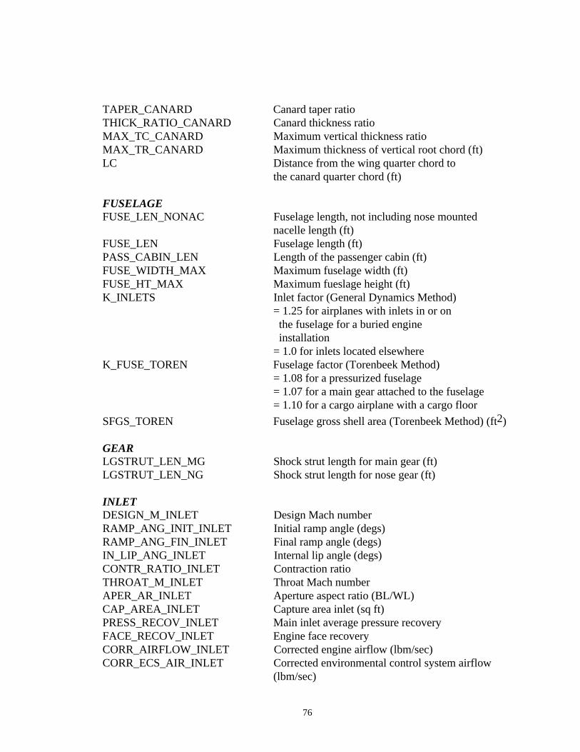
76
TAPER_CANARD Canard taper ratioTHICK_RATIO_CANARD Canard thickness ratioMAX_TC_CANARD Maximum vertical thickness ratioMAX_TR_CANARD Maximum thickness of vertical root chord (ft)LC Distance from the wing quarter chord to
the canard quarter chord (ft)
FUSELAGEFUSE_LEN_NONAC Fuselage length, not including nose mounted
nacelle length (ft)FUSE_LEN Fuselage length (ft)PASS_CABIN_LEN Length of the passenger cabin (ft)FUSE_WIDTH_MAX Maximum fuselage width (ft)FUSE_HT_MAX Maximum fueslage height (ft)K_INLETS Inlet factor (General Dynamics Method)
= 1.25 for airplanes with inlets in or on the fuselage for a buried engine installation= 1.0 for inlets located elsewhere
K_FUSE_TOREN Fuselage factor (Torenbeek Method)= 1.08 for a pressurized fuselage= 1.07 for a main gear attached to the fuselage= 1.10 for a cargo airplane with a cargo floor
SFGS_TOREN Fuselage gross shell area (Torenbeek Method) (ft2)
GEARLGSTRUT_LEN_MG Shock strut length for main gear (ft)LGSTRUT_LEN_NG Shock strut length for nose gear (ft)
INLETDESIGN_M_INLET Design Mach numberRAMP_ANG_INIT_INLET Initial ramp angle (degs)RAMP_ANG_FIN_INLET Final ramp angle (degs)IN_LIP_ANG_INLET Internal lip angle (degs)CONTR_RATIO_INLET Contraction ratioTHROAT_M_INLET Throat Mach numberAPER_AR_INLET Aperture aspect ratio (BL/WL)CAP_AREA_INLET Capture area inlet (sq ft)PRESS_RECOV_INLET Main inlet average pressure recoveryFACE_RECOV_INLET Engine face recoveryCORR_AIRFLOW_INLET Corrected engine airflow (lbm/sec)CORR_ECS_AIR_INLET Corrected environmental control system airflow
(lbm/sec)
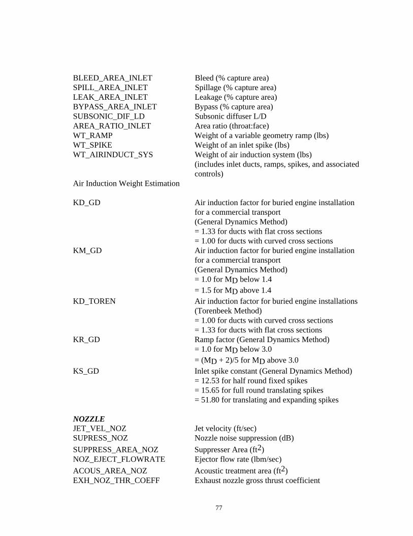
77
BLEED_AREA_INLET Bleed (% capture area)SPILL_AREA_INLET Spillage (% capture area)LEAK_AREA_INLET Leakage (% capture area)BYPASS_AREA_INLET Bypass (% capture area)SUBSONIC_DIF_LD Subsonic diffuser L/DAREA_RATIO_INLET Area ratio (throat:face)WT_RAMP Weight of a variable geometry ramp (lbs)WT_SPIKE Weight of an inlet spike (lbs)WT_AIRINDUCT_SYS Weight of air induction system (lbs)
(includes inlet ducts, ramps, spikes, and associated controls)
Air Induction Weight Estimation
KD_GD Air induction factor for buried engine installation for a commercial transport(General Dynamics Method)= 1.33 for ducts with flat cross sections= 1.00 for ducts with curved cross sections
KM_GD Air induction factor for buried engine installation for a commercial transport(General Dynamics Method)= 1.0 for MD below 1.4= 1.5 for MD above 1.4
KD_TOREN Air induction factor for buried engine installations (Torenbeek Method)= 1.00 for ducts with curved cross sections= 1.33 for ducts with flat cross sections
KR_GD Ramp factor (General Dynamics Method)= 1.0 for MD below 3.0= (MD + 2)/5 for MD above 3.0
KS_GD Inlet spike constant (General Dynamics Method)= 12.53 for half round fixed spikes= 15.65 for full round translating spikes= 51.80 for translating and expanding spikes
NOZZLEJET_VEL_NOZ Jet velocity (ft/sec)SUPRESS_NOZ Nozzle noise suppression (dB)
SUPPRESS_AREA_NOZ Suppresser Area (ft2)NOZ_EJECT_FLOWRATE Ejector flow rate (lbm/sec)
ACOUS_AREA_NOZ Acoustic treatment area (ft2)EXH_NOZ_THR_COEFF Exhaust nozzle gross thrust coefficient
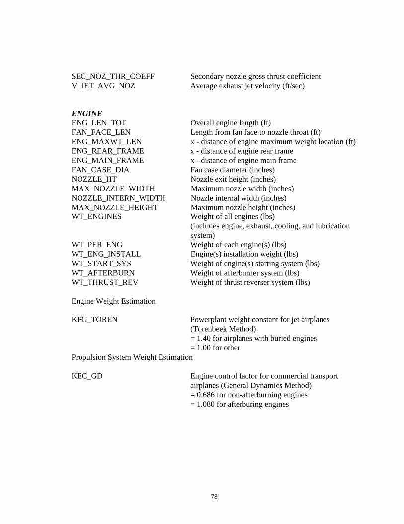
78
SEC_NOZ_THR_COEFF Secondary nozzle gross thrust coefficientV_JET_AVG_NOZ Average exhaust jet velocity (ft/sec)
ENGINEENG_LEN_TOT Overall engine length (ft)FAN_FACE_LEN Length from fan face to nozzle throat (ft)ENG_MAXWT_LEN x - distance of engine maximum weight location (ft)ENG_REAR_FRAME x - distance of engine rear frameENG_MAIN_FRAME x - distance of engine main frameFAN_CASE_DIA Fan case diameter (inches)NOZZLE_HT Nozzle exit height (inches)MAX_NOZZLE_WIDTH Maximum nozzle width (inches)NOZZLE_INTERN_WIDTH Nozzle internal width (inches)MAX_NOZZLE_HEIGHT Maximum nozzle height (inches)WT_ENGINES Weight of all engines (lbs)
(includes engine, exhaust, cooling, and lubrication system)
WT_PER_ENG Weight of each engine(s) (lbs)WT_ENG_INSTALL Engine(s) installation weight (lbs)WT_START_SYS Weight of engine(s) starting system (lbs)WT_AFTERBURN Weight of afterburner system (lbs)WT_THRUST_REV Weight of thrust reverser system (lbs)
Engine Weight Estimation
KPG_TOREN Powerplant weight constant for jet airplanes (Torenbeek Method)= 1.40 for airplanes with buried engines= 1.00 for other
Propulsion System Weight Estimation
KEC_GD Engine control factor for commercial transport airplanes (General Dynamics Method)= 0.686 for non-afterburning engines= 1.080 for afterburing engines
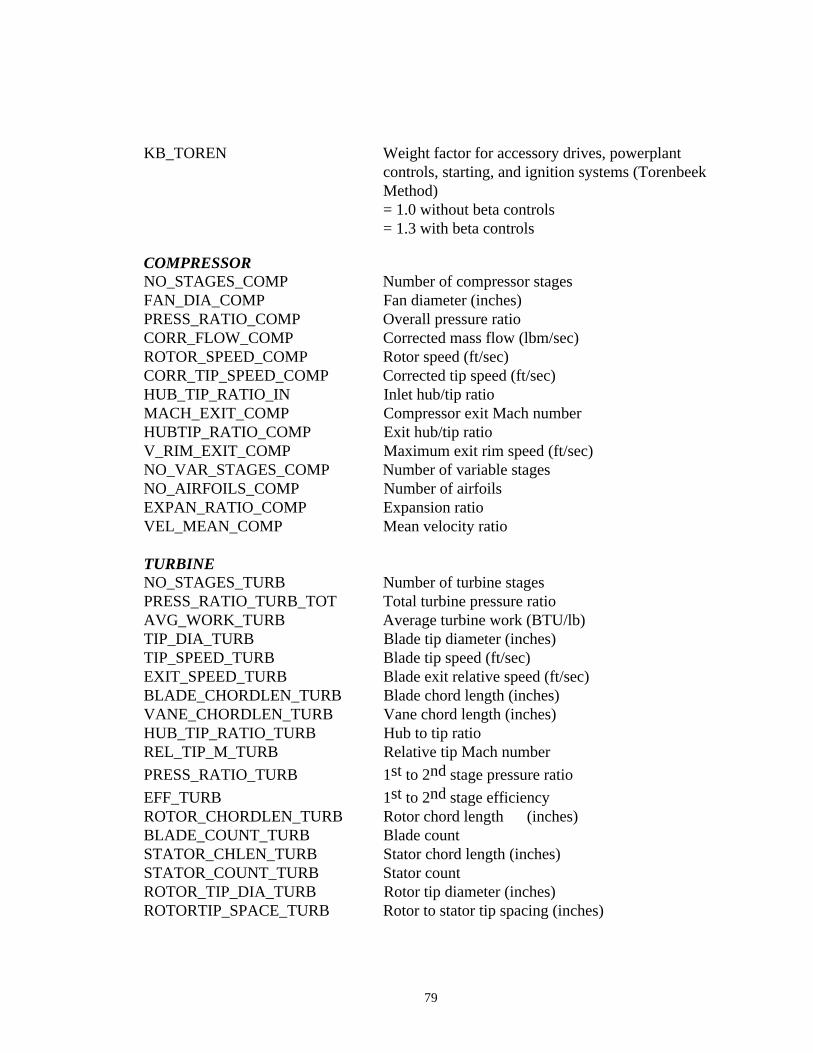
79
KB_TOREN Weight factor for accessory drives, powerplant controls, starting, and ignition systems (Torenbeek Method)= 1.0 without beta controls= 1.3 with beta controls
COMPRESSORNO_STAGES_COMP Number of compressor stagesFAN_DIA_COMP Fan diameter (inches)PRESS_RATIO_COMP Overall pressure ratioCORR_FLOW_COMP Corrected mass flow (lbm/sec)ROTOR_SPEED_COMP Rotor speed (ft/sec)CORR_TIP_SPEED_COMP Corrected tip speed (ft/sec)HUB_TIP_RATIO_IN Inlet hub/tip ratioMACH_EXIT_COMP Compressor exit Mach numberHUBTIP_RATIO_COMP Exit hub/tip ratioV_RIM_EXIT_COMP Maximum exit rim speed (ft/sec)NO_VAR_STAGES_COMP Number of variable stagesNO_AIRFOILS_COMP Number of airfoilsEXPAN_RATIO_COMP Expansion ratioVEL_MEAN_COMP Mean velocity ratio
TURBINENO_STAGES_TURB Number of turbine stagesPRESS_RATIO_TURB_TOT Total turbine pressure ratioAVG_WORK_TURB Average turbine work (BTU/lb)TIP_DIA_TURB Blade tip diameter (inches)TIP_SPEED_TURB Blade tip speed (ft/sec)EXIT_SPEED_TURB Blade exit relative speed (ft/sec)BLADE_CHORDLEN_TURB Blade chord length (inches)VANE_CHORDLEN_TURB Vane chord length (inches)HUB_TIP_RATIO_TURB Hub to tip ratioREL_TIP_M_TURB Relative tip Mach number
PRESS_RATIO_TURB 1st to 2nd stage pressure ratio
EFF_TURB 1st to 2nd stage efficiencyROTOR_CHORDLEN_TURB Rotor chord length (inches)BLADE_COUNT_TURB Blade countSTATOR_CHLEN_TURB Stator chord length (inches)STATOR_COUNT_TURB Stator countROTOR_TIP_DIA_TURB Rotor tip diameter (inches)ROTORTIP_SPACE_TURB Rotor to stator tip spacing (inches)
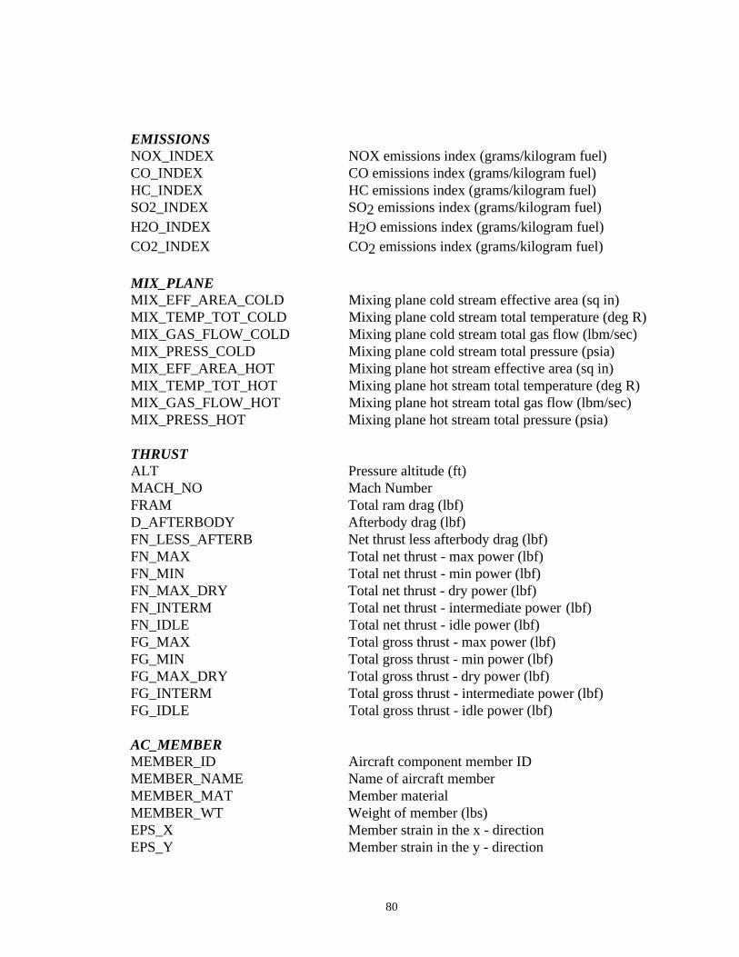
80
EMISSIONSNOX_INDEX NOX emissions index (grams/kilogram fuel)CO_INDEX CO emissions index (grams/kilogram fuel)HC_INDEX HC emissions index (grams/kilogram fuel)SO2_INDEX SO2 emissions index (grams/kilogram fuel)H2O_INDEX H2O emissions index (grams/kilogram fuel)CO2_INDEX CO2 emissions index (grams/kilogram fuel)
MIX_PLANEMIX_EFF_AREA_COLD Mixing plane cold stream effective area (sq in)MIX_TEMP_TOT_COLD Mixing plane cold stream total temperature (deg R)MIX_GAS_FLOW_COLD Mixing plane cold stream total gas flow (lbm/sec)MIX_PRESS_COLD Mixing plane cold stream total pressure (psia)MIX_EFF_AREA_HOT Mixing plane hot stream effective area (sq in)MIX_TEMP_TOT_HOT Mixing plane hot stream total temperature (deg R)MIX_GAS_FLOW_HOT Mixing plane hot stream total gas flow (lbm/sec)MIX_PRESS_HOT Mixing plane hot stream total pressure (psia)
THRUSTALT Pressure altitude (ft)MACH_NO Mach NumberFRAM Total ram drag (lbf)D_AFTERBODY Afterbody drag (lbf)FN_LESS_AFTERB Net thrust less afterbody drag (lbf)FN_MAX Total net thrust - max power (lbf)FN_MIN Total net thrust - min power (lbf)FN_MAX_DRY Total net thrust - dry power (lbf)FN_INTERM Total net thrust - intermediate power (lbf)FN_IDLE Total net thrust - idle power (lbf)FG_MAX Total gross thrust - max power (lbf)FG_MIN Total gross thrust - min power (lbf)FG_MAX_DRY Total gross thrust - dry power (lbf)FG_INTERM Total gross thrust - intermediate power (lbf)FG_IDLE Total gross thrust - idle power (lbf)
AC_MEMBERMEMBER_ID Aircraft component member IDMEMBER_NAME Name of aircraft memberMEMBER_MAT Member materialMEMBER_WT Weight of member (lbs)EPS_X Member strain in the x - directionEPS_Y Member strain in the y - direction
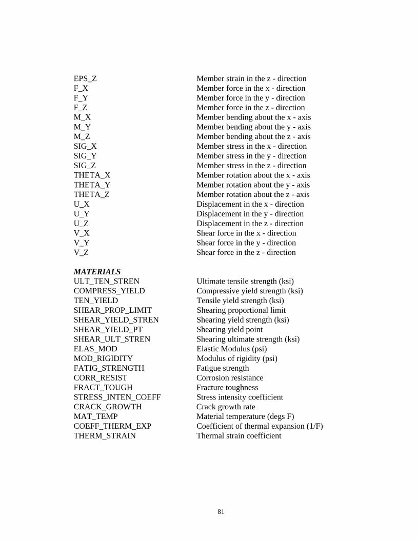
81
EPS_Z Member strain in the z - directionF_X Member force in the x - directionF_Y Member force in the y - directionF_Z Member force in the z - directionM_X Member bending about the x - axisM_Y Member bending about the y - axisM_Z Member bending about the z - axisSIG_X Member stress in the x - directionSIG_Y Member stress in the y - directionSIG_Z Member stress in the z - directionTHETA_X Member rotation about the x - axisTHETA_Y Member rotation about the y - axisTHETA_Z Member rotation about the z - axisU_X Displacement in the x - directionU_Y Displacement in the y - directionU_Z Displacement in the z - directionV_X Shear force in the x - directionV_Y Shear force in the y - directionV_Z Shear force in the z - direction
MATERIALSULT_TEN_STREN Ultimate tensile strength (ksi)COMPRESS_YIELD Compressive yield strength (ksi)TEN_YIELD Tensile yield strength (ksi)SHEAR_PROP_LIMIT Shearing proportional limitSHEAR_YIELD_STREN Shearing yield strength (ksi)SHEAR_YIELD_PT Shearing yield pointSHEAR_ULT_STREN Shearing ultimate strength (ksi)ELAS_MOD Elastic Modulus (psi)MOD_RIGIDITY Modulus of rigidity (psi)FATIG_STRENGTH Fatigue strengthCORR_RESIST Corrosion resistanceFRACT_TOUGH Fracture toughnessSTRESS_INTEN_COEFF Stress intensity coefficientCRACK_GROWTH Crack growth rateMAT_TEMP Material temperature (degs F)COEFF_THERM_EXP Coefficient of thermal expansion (1/F)THERM_STRAIN Thermal strain coefficient
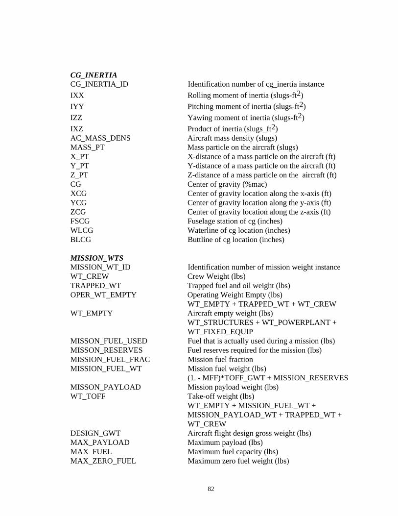
82
CG_INERTIACG_INERTIA_ID Identification number of cg_inertia instance
IXX Rolling moment of inertia (slugs-ft2)
IYY Pitching moment of inertia (slugs-ft2)
IZZ Yawing moment of inertia (slugs-ft2)
IXZ Product of inertia (slugs_ft2)AC_MASS_DENS Aircraft mass density (slugs)MASS_PT Mass particle on the aircraft (slugs)X_PT X-distance of a mass particle on the aircraft (ft)Y_PT Y-distance of a mass particle on the aircraft (ft)Z_PT Z-distance of a mass particle on the aircraft (ft)CG Center of gravity (%mac)XCG Center of gravity location along the x-axis (ft)YCG Center of gravity location along the y-axis (ft)ZCG Center of gravity location along the z-axis (ft)FSCG Fuselage station of cg (inches)WLCG Waterline of cg location (inches)BLCG Buttline of cg location (inches)
MISSION_WTSMISSION_WT_ID Identification number of mission weight instanceWT_CREW Crew Weight (lbs)TRAPPED_WT Trapped fuel and oil weight (lbs)OPER_WT_EMPTY Operating Weight Empty (lbs)
WT_EMPTY + TRAPPED_WT + WT_CREWWT_EMPTY Aircraft empty weight (lbs)
WT_STRUCTURES + WT_POWERPLANT +WT_FIXED_EQUIP
MISSON_FUEL_USED Fuel that is actually used during a mission (lbs)MISSON_RESERVES Fuel reserves required for the mission (lbs)MISSION_FUEL_FRAC Mission fuel fractionMISSION_FUEL_WT Mission fuel weight (lbs)
(1. - MFF)*TOFF_GWT + MISSION_RESERVESMISSON_PAYLOAD Mission payload weight (lbs)WT_TOFF Take-off weight (lbs)
WT_EMPTY + MISSION_FUEL_WT +MISSION_PAYLOAD_WT + TRAPPED_WT + WT_CREW
DESIGN_GWT Aircraft flight design gross weight (lbs)MAX_PAYLOAD Maximum payload (lbs)MAX_FUEL Maximum fuel capacity (lbs)MAX_ZERO_FUEL Maximum zero fuel weight (lbs)
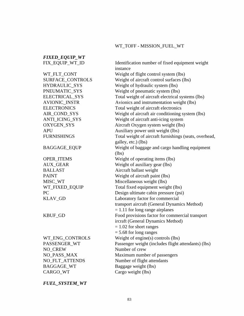
83
WT_TOFF - MISSION_FUEL_WT
FIXED_EQUIP_WTFIX_EQUIP_WT_ID Identification number of fixed equipment weight
instanceWT_FLT_CONT Weight of flight control system (lbs)SURFACE_CONTROLS Weight of aircraft control surfaces (lbs)HYDRAULIC_SYS Weight of hydraulic system (lbs)PNEUMATIC_SYS Weight of pneumatic system (lbs)ELECTRICAL_SYS Total weight of aircraft electrical systems (lbs)AVIONIC_INSTR Avionics and instrumentation weight (lbs)ELECTRONICS Total weight of aircraft electronicsAIR_COND_SYS Weight of aircraft air conditioning system (lbs)ANTI_ICING_SYS Weight of aircraft anti-icing systemOXYGEN_SYS Aircraft Oxygen system weight (lbs)APU Auxiliary power unit weight (lbs)FURNISHINGS Total weight of aircraft furnishings (seats, overhead,
galley, etc.) (lbs)BAGGAGE_EQUP Weight of baggage and cargo handling equipment
(lbs)OPER_ITEMS Weight of operating items (lbs)AUX_GEAR Weight of auxiliary gear (lbs)BALLAST Aircraft ballast weightPAINT Weight of aircraft paint (lbs)MISC_WT Miscellaneous weight (lbs)WT_FIXED_EQUIP Total fixed equipment weight (lbs)PC Design ultimate cabin pressure (psi)KLAV_GD Laboratory factor for commercial
transport aircraft (General Dynamics Method)= 1.11 for long range airplanes
KBUF_GD Food provisions factor for commercial transport ircraft (General Dynamics Method)= 1.02 for short ranges= 5.68 for long ranges
WT_ENG_CONTROLS Weight of engine(s) controls (lbs)PASSENGER_WT Passenger weight (includes flight attendants) (lbs)NO_CREW Number of crewNO_PASS_MAX Maximum number of passengersNO_FLT_ATTENDS Number of flight attendantsBAGGAGE_WT Baggage weight (lbs)CARGO_WT Cargo weight (lbs)
FUEL_SYSTEM_WT
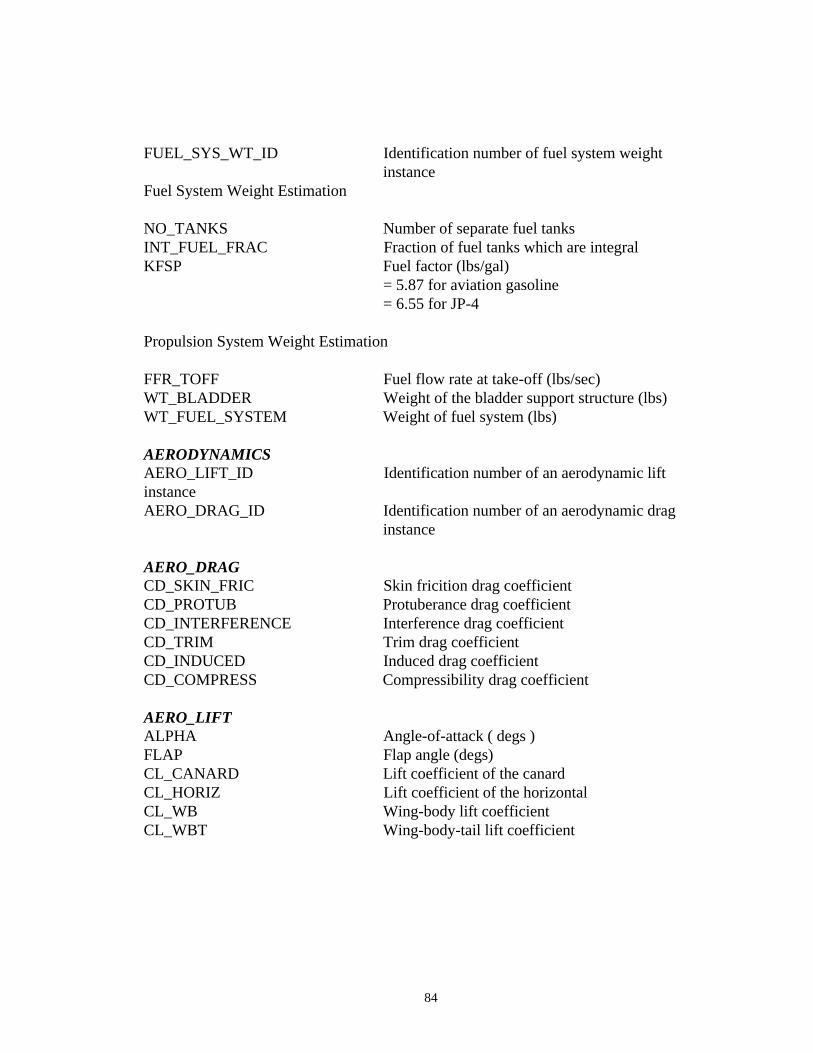
84
FUEL_SYS_WT_ID Identification number of fuel system weightinstance
Fuel System Weight Estimation
NO_TANKS Number of separate fuel tanksINT_FUEL_FRAC Fraction of fuel tanks which are integralKFSP Fuel factor (lbs/gal)
= 5.87 for aviation gasoline= 6.55 for JP-4
Propulsion System Weight Estimation
FFR_TOFF Fuel flow rate at take-off (lbs/sec)WT_BLADDER Weight of the bladder support structure (lbs)WT_FUEL_SYSTEM Weight of fuel system (lbs)
AERODYNAMICSAERO_LIFT_ID Identification number of an aerodynamic liftinstanceAERO_DRAG_ID Identification number of an aerodynamic drag
instance
AERO_DRAGCD_SKIN_FRIC Skin fricition drag coefficientCD_PROTUB Protuberance drag coefficientCD_INTERFERENCE Interference drag coefficientCD_TRIM Trim drag coefficientCD_INDUCED Induced drag coefficientCD_COMPRESS Compressibility drag coefficient
AERO_LIFTALPHA Angle-of-attack ( degs )FLAP Flap angle (degs)CL_CANARD Lift coefficient of the canardCL_HORIZ Lift coefficient of the horizontalCL_WB Wing-body lift coefficientCL_WBT Wing-body-tail lift coefficient
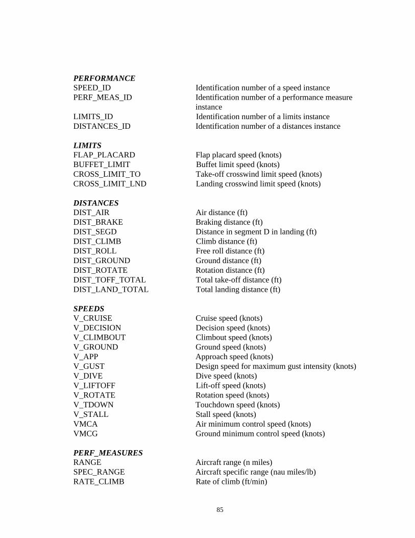
85
PERFORMANCESPEED_ID Identification number of a speed instancePERF_MEAS_ID Identification number of a performance measure
instanceLIMITS_ID Identification number of a limits instanceDISTANCES_ID Identification number of a distances instance
LIMITSFLAP_PLACARD Flap placard speed (knots)BUFFET_LIMIT Buffet limit speed (knots)CROSS_LIMIT_TO Take-off crosswind limit speed (knots)CROSS_LIMIT_LND Landing crosswind limit speed (knots)
DISTANCESDIST_AIR Air distance (ft)DIST_BRAKE Braking distance (ft)DIST_SEGD Distance in segment D in landing (ft)DIST_CLIMB Climb distance (ft)DIST_ROLL Free roll distance (ft)DIST_GROUND Ground distance (ft)DIST_ROTATE Rotation distance (ft)DIST_TOFF_TOTAL Total take-off distance (ft)DIST_LAND_TOTAL Total landing distance (ft)
SPEEDSV_CRUISE Cruise speed (knots)V_DECISION Decision speed (knots)V_CLIMBOUT Climbout speed (knots)V_GROUND Ground speed (knots)V_APP Approach speed (knots)V_GUST Design speed for maximum gust intensity (knots)V_DIVE Dive speed (knots)V_LIFTOFF Lift-off speed (knots)V_ROTATE Rotation speed (knots)V_TDOWN Touchdown speed (knots)V_STALL Stall speed (knots)VMCA Air minimum control speed (knots)VMCG Ground minimum control speed (knots)
PERF_MEASURESRANGE Aircraft range (n miles)SPEC_RANGE Aircraft specific range (nau miles/lb)RATE_CLIMB Rate of climb (ft/min)
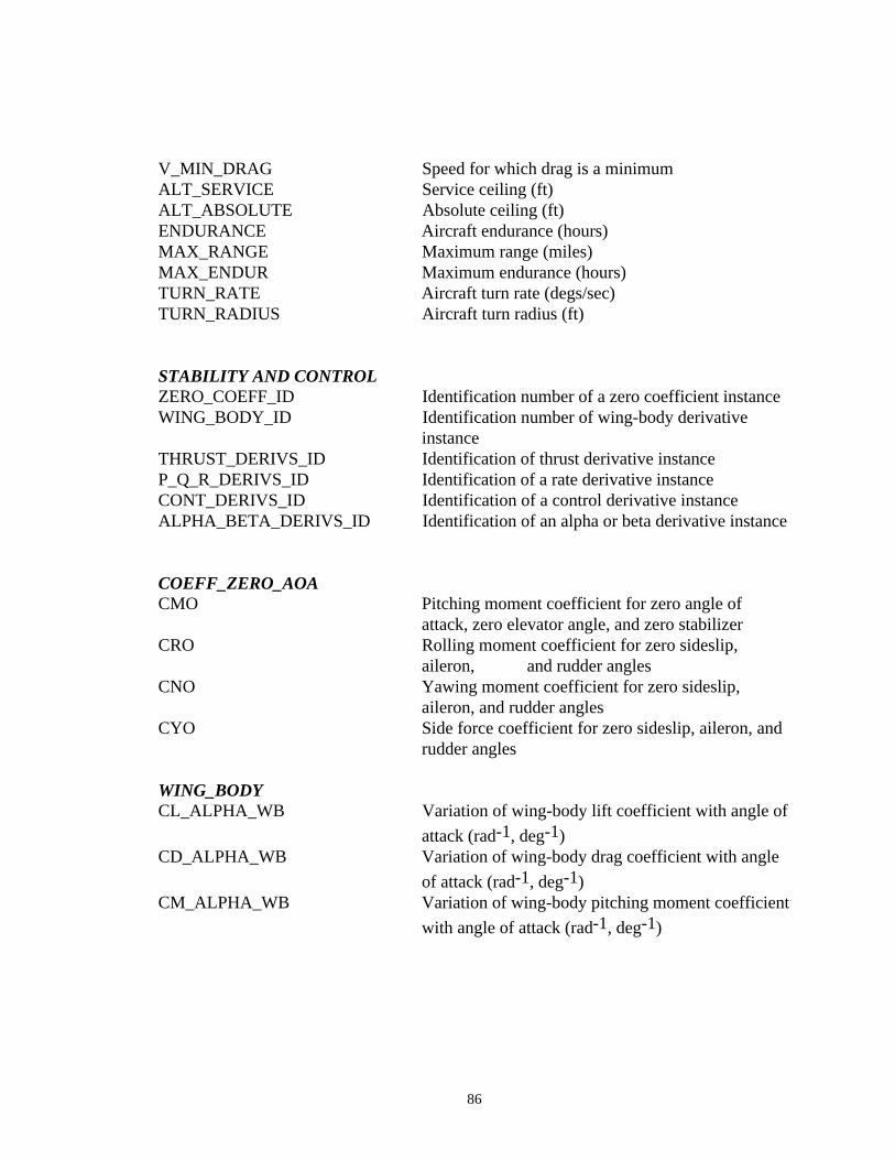
86
V_MIN_DRAG Speed for which drag is a minimumALT_SERVICE Service ceiling (ft)ALT_ABSOLUTE Absolute ceiling (ft)ENDURANCE Aircraft endurance (hours)MAX_RANGE Maximum range (miles)MAX_ENDUR Maximum endurance (hours)TURN_RATE Aircraft turn rate (degs/sec)TURN_RADIUS Aircraft turn radius (ft)
STABILITY AND CONTROLZERO_COEFF_ID Identification number of a zero coefficient instanceWING_BODY_ID Identification number of wing-body derivative
instanceTHRUST_DERIVS_ID Identification of thrust derivative instanceP_Q_R_DERIVS_ID Identification of a rate derivative instanceCONT_DERIVS_ID Identification of a control derivative instanceALPHA_BETA_DERIVS_ID Identification of an alpha or beta derivative instance
COEFF_ZERO_AOACMO Pitching moment coefficient for zero angle of
attack, zero elevator angle, and zero stabilizerCRO Rolling moment coefficient for zero sideslip,
aileron, and rudder anglesCNO Yawing moment coefficient for zero sideslip,
aileron, and rudder anglesCYO Side force coefficient for zero sideslip, aileron, and
rudder angles
WING_BODYCL_ALPHA_WB Variation of wing-body lift coefficient with angle of
attack (rad-1, deg-1)CD_ALPHA_WB Variation of wing-body drag coefficient with angle
of attack (rad-1, deg-1)CM_ALPHA_WB Variation of wing-body pitching moment coefficient
with angle of attack (rad-1, deg-1)
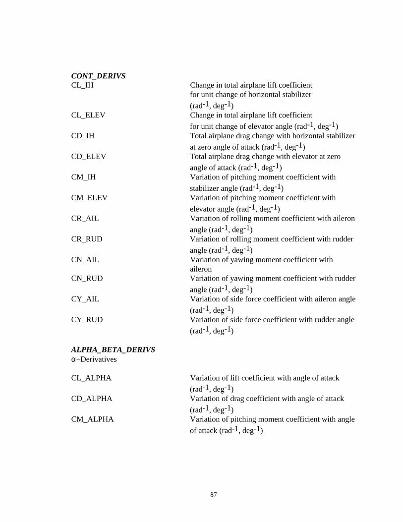
87
CONT_DERIVSCL_IH Change in total airplane lift coefficient
for unit change of horizontal stabilizer
(rad-1, deg-1)CL_ELEV Change in total airplane lift coefficient
for unit change of elevator angle (rad-1, deg-1)CD_IH Total airplane drag change with horizontal stabilizer
at zero angle of attack (rad-1, deg-1)CD_ELEV Total airplane drag change with elevator at zero
angle of attack (rad-1, deg-1)CM_IH Variation of pitching moment coefficient with
stabilizer angle (rad-1, deg-1)CM_ELEV Variation of pitching moment coefficient with
elevator angle (rad-1, deg-1)CR_AIL Variation of rolling moment coefficient with aileron
angle (rad-1, deg-1)CR_RUD Variation of rolling moment coefficient with rudder
angle (rad-1, deg-1)CN_AIL Variation of yawing moment coefficient with
aileron CN_RUD Variation of yawing moment coefficient with rudder
angle (rad-1, deg-1)CY_AIL Variation of side force coefficient with aileron angle
(rad-1, deg-1)CY_RUD Variation of side force coefficient with rudder angle
(rad-1, deg-1)
ALPHA_BETA_DERIVSα−Derivatives
CL_ALPHA Variation of lift coefficient with angle of attack
(rad-1, deg-1)CD_ALPHA Variation of drag coefficient with angle of attack
(rad-1, deg-1)CM_ALPHA Variation of pitching moment coefficient with angle
of attack (rad-1, deg-1)
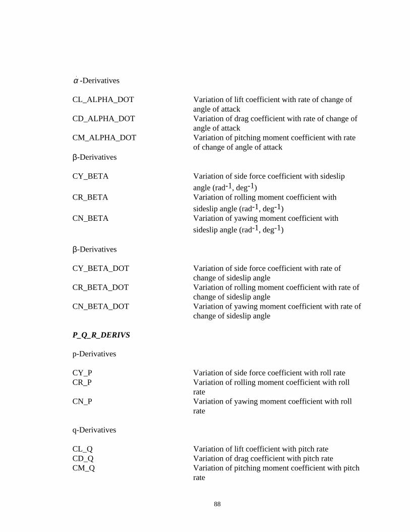
88
α.-Derivatives
CL_ALPHA_DOT Variation of lift coefficient with rate of change of angle of attack
CD_ALPHA_DOT Variation of drag coefficient with rate of change of angle of attack
CM_ALPHA_DOT Variation of pitching moment coefficient with rate of change of angle of attack
β-Derivatives
CY_BETA Variation of side force coefficient with sideslip
angle (rad-1, deg-1)CR_BETA Variation of rolling moment coefficient with
sideslip angle (rad-1, deg-1)CN_BETA Variation of yawing moment coefficient with
sideslip angle (rad-1, deg-1)
β-Derivatives
CY_BETA_DOT Variation of side force coefficient with rate of change of sideslip angle
CR_BETA_DOT Variation of rolling moment coefficient with rate of change of sideslip angle
CN_BETA_DOT Variation of yawing moment coefficient with rate ofchange of sideslip angle
P_Q_R_DERIVS
p-Derivatives
CY_P Variation of side force coefficient with roll rateCR_P Variation of rolling moment coefficient with roll
rateCN_P Variation of yawing moment coefficient with roll
rate
q-Derivatives
CL_Q Variation of lift coefficient with pitch rateCD_Q Variation of drag coefficient with pitch rateCM_Q Variation of pitching moment coefficient with pitch
rate
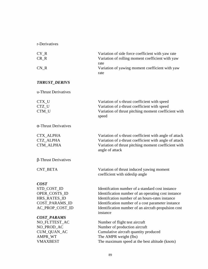
89
r-Derivatives
CY_R Variation of side force coefficient with yaw rateCR_R Variation of rolling moment coefficient with yaw
rateCN_R Variation of yawing moment coefficient with yaw
rate
THRUST_DERIVS
u-Thrust Derivatives
CTX_U Variation of x-thrust coefficient with speedCTZ_U Variation of z-thrust coefficient with speedCTM_U Variation of thrust pitching moment coefficient with
speed
α-Thrust Derivatives
CTX_ALPHA Variation of x-thrust coefficient with angle of attackCTZ_ALPHA Variation of z-thrust coefficient with angle of attackCTM_ALPHA Variation of thrust pitching moment coefficient with
angle of attack
β-Thrust Derivatives
CNT_BETA Variation of thrust induced yawing moment coefficient with sideslip angle
COSTSTD_COST_ID Identifcation number of a standard cost instanceOPER_COSTS_ID Identification number of an operating cost instanceHRS_RATES_ID Identifcation number of an hours-rates instanceCOST_PARAMS_ID Identification number of a cost parameter instanceAC_PROP_COST_ID Identification number of an aircraft-propulsion cost
instanceCOST_PARAMSNO_FLTTEST_AC Number of flight test aircraftNO_PROD_AC Number of production aircraftCUM_QUAN_AC Cumulative aircraft quantity producedAMPR_WT The AMPR weight (lbs)VMAXBEST The maximum speed at the best altitude (knots)
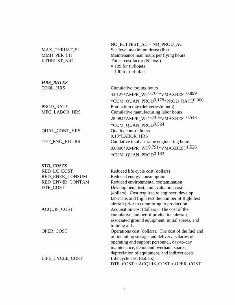
90
NO_FLTTEST_AC + NO_PROD_ACMAX_THRUST_SL Sea level maximum thrust (lbs)MMH_PER_FH Maintenance man hours per flying hoursKTHRUST_NIC Thrust cost factor (Nicloai)
= 109 for turbojets= 130 for turbofans
HRS_RATESTOOL_HRS Cumulative tooling hours
4.0127*AMPR_WT0.764*VMAXBEST 0.899
*CUM_QUAN_PROD0.178*PROD_RATE0.066
PROD_RATE Production rate (deliveries/month)MFG_LABOR_HRS Cumulative manufacturing labor hours
28.984*AMPR_WT0.740*VMAXBEST 0.543
*CUM_QUAN_PROD0.524
QUAL_CONT_HRS Quality control hours0.13*LABOR_HRS
TOT_ENG_HOURS Cumlative total airframe engineering hours
0.0396*AMPR_WT0.791*VMAXBEST 1.526
*CUM_QUAN_PROD0.183
STD_COSTSRED_LC_COST Reduced life cycle cost (dollars)RED_ENER_CONSUM Reduced energy consumptionRED_ENVIR_CONTAM Reduced environmental contaminationDTE_COST Development, test, and evaluation cost
(dollars). Cost required to engineer, develop, fabricate, and flight test the number of flight test aircraft prior to committing to production
ACQUIS_COST Acquisition cost (dollars). The cost of the cumulative number of production aircraft, associated ground equipment, initial spares, and training aids.
OPER_COST Operations cost (dollars). The cost of the fuel and oil including storage and delivery, salaries of operating and support personnel, day-to-day maintenance, depot and overhaul, spares, depreciation of equipment, and indirect costs.
LIFE_CYCLE_COST Life cycle cost (dollars)DTE_COST + ACQUIS_COST + OPER_COST
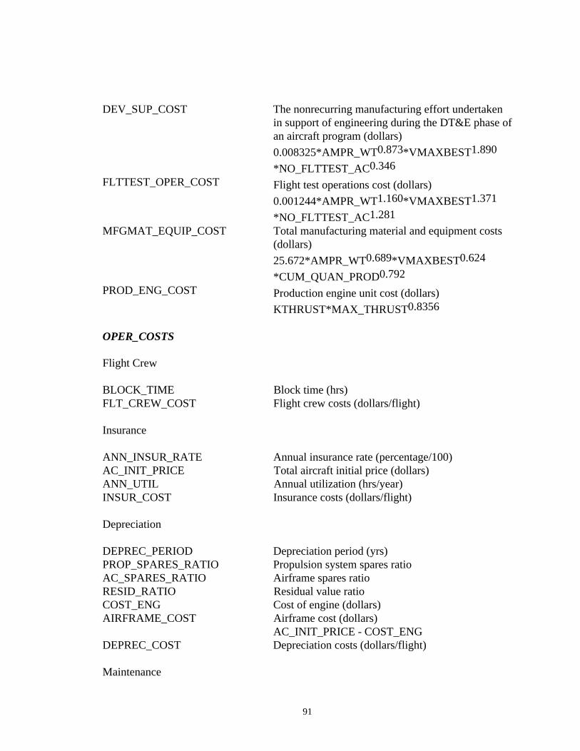
91
DEV_SUP_COST The nonrecurring manufacturing effort undertaken in support of engineering during the DT&E phase ofan aircraft program (dollars)
0.008325*AMPR_WT0.873*VMAXBEST 1.890
*NO_FLTTEST_AC0.346
FLTTEST_OPER_COST Flight test operations cost (dollars)
0.001244*AMPR_WT1.160*VMAXBEST 1.371
*NO_FLTTEST_AC1.281
MFGMAT_EQUIP_COST Total manufacturing material and equipment costs (dollars)
25.672*AMPR_WT0.689*VMAXBEST 0.624
*CUM_QUAN_PROD0.792
PROD_ENG_COST Production engine unit cost (dollars)
KTHRUST*MAX_THRUST0.8356
OPER_COSTS
Flight Crew
BLOCK_TIME Block time (hrs)FLT_CREW_COST Flight crew costs (dollars/flight)
Insurance
ANN_INSUR_RATE Annual insurance rate (percentage/100)AC_INIT_PRICE Total aircraft initial price (dollars)ANN_UTIL Annual utilization (hrs/year)INSUR_COST Insurance costs (dollars/flight)
Depreciation
DEPREC_PERIOD Depreciation period (yrs)PROP_SPARES_RATIO Propulsion system spares ratioAC_SPARES_RATIO Airframe spares ratioRESID_RATIO Residual value ratioCOST_ENG Cost of engine (dollars)AIRFRAME_COST Airframe cost (dollars)
AC_INIT_PRICE - COST_ENGDEPREC_COST Depreciation costs (dollars/flight)
Maintenance
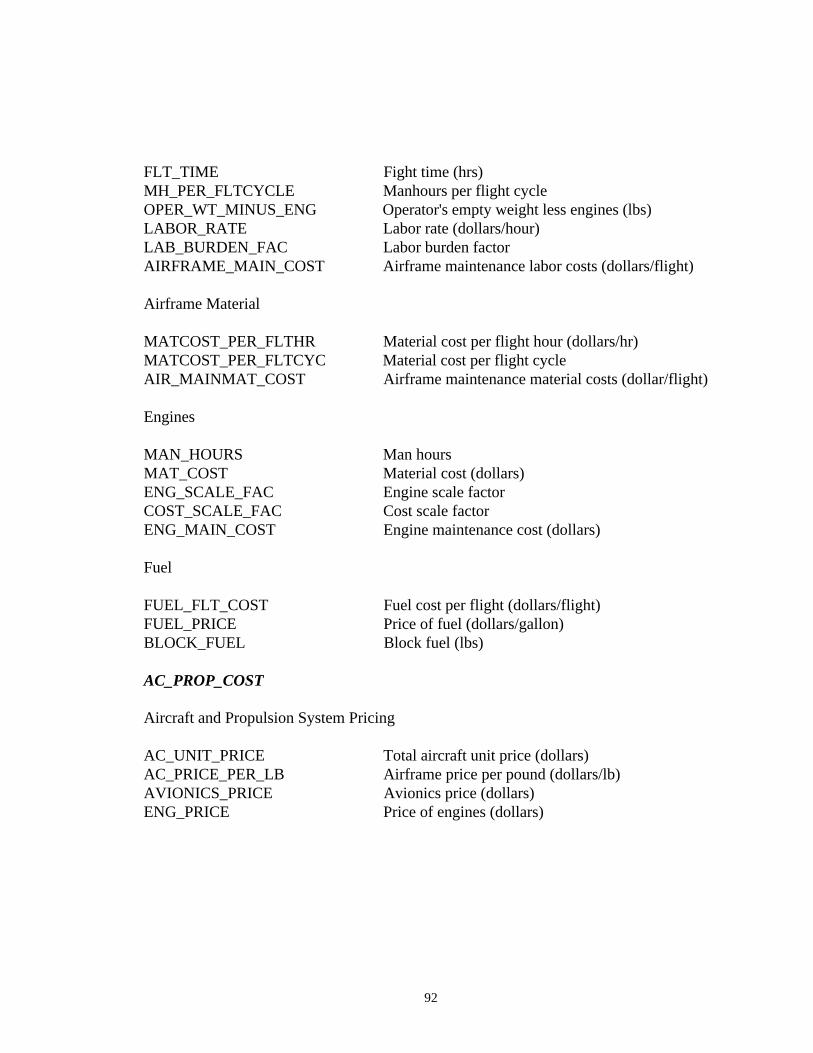
92
FLT_TIME Fight time (hrs)MH_PER_FLTCYCLE Manhours per flight cycleOPER_WT_MINUS_ENG Operator's empty weight less engines (lbs)LABOR_RATE Labor rate (dollars/hour)LAB_BURDEN_FAC Labor burden factorAIRFRAME_MAIN_COST Airframe maintenance labor costs (dollars/flight)
Airframe Material
MATCOST_PER_FLTHR Material cost per flight hour (dollars/hr)MATCOST_PER_FLTCYC Material cost per flight cycleAIR_MAINMAT_COST Airframe maintenance material costs (dollar/flight)
Engines
MAN_HOURS Man hoursMAT_COST Material cost (dollars)ENG_SCALE_FAC Engine scale factorCOST_SCALE_FAC Cost scale factorENG_MAIN_COST Engine maintenance cost (dollars)
Fuel
FUEL_FLT_COST Fuel cost per flight (dollars/flight)FUEL_PRICE Price of fuel (dollars/gallon)BLOCK_FUEL Block fuel (lbs)
AC_PROP_COST
Aircraft and Propulsion System Pricing
AC_UNIT_PRICE Total aircraft unit price (dollars)AC_PRICE_PER_LB Airframe price per pound (dollars/lb)AVIONICS_PRICE Avionics price (dollars)ENG_PRICE Price of engines (dollars)
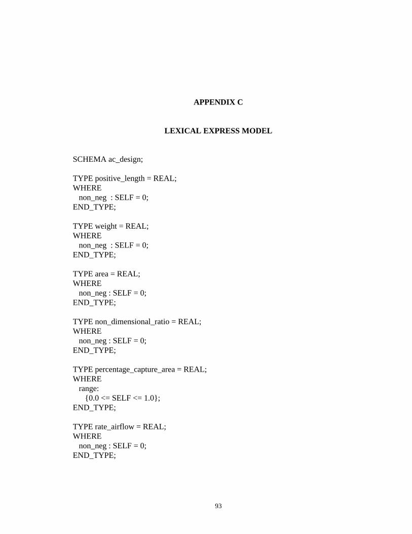
93
APPENDIX C
LEXICAL EXPRESS MODEL
SCHEMA ac_design;
TYPE positive_length = REAL;WHERE non_neg : SELF = 0;END_TYPE;
TYPE weight = REAL;WHERE non_neg : SELF = 0;END_TYPE;
TYPE area = REAL;WHERE non_neg : SELF = 0;END_TYPE;
TYPE non_dimensional_ratio = REAL;WHERE non_neg : SELF = 0;END_TYPE;
TYPE percentage_capture_area = REAL;WHERE range: {0.0 <= SELF <= 1.0};END_TYPE;
TYPE rate_airflow = REAL;WHERE non_neg : SELF = 0;END_TYPE;
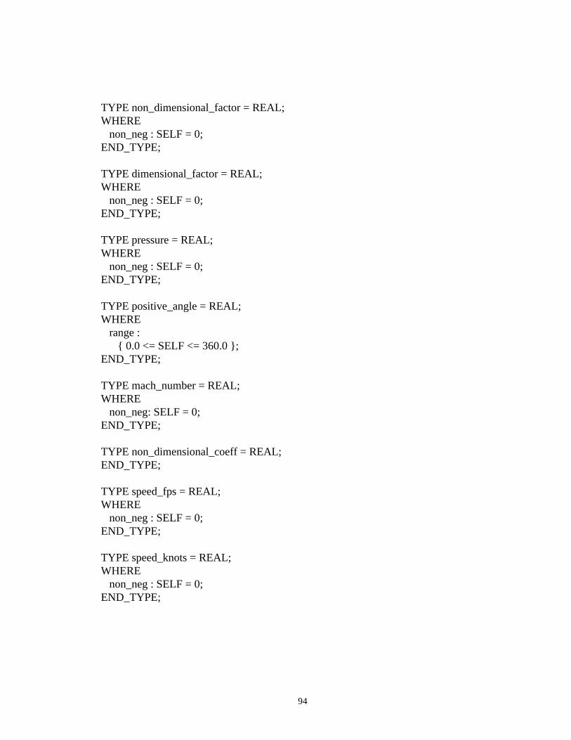
94
TYPE non_dimensional_factor = REAL;WHERE non_neg : SELF = 0;END_TYPE;
TYPE dimensional_factor = REAL;WHERE non_neg : SELF = 0;END_TYPE;
TYPE pressure = REAL;WHERE non_neg : SELF = 0;END_TYPE;
TYPE positive_angle = REAL;WHERE range : { 0.0 <= SELF <= 360.0 };END_TYPE;
TYPE mach_number = REAL;WHERE non_neg: SELF = 0;END_TYPE;
TYPE non_dimensional_coeff = REAL;END_TYPE;
TYPE speed_fps = REAL;WHERE non_neg : SELF = 0;END_TYPE;
TYPE speed_knots = REAL;WHERE non_neg : SELF = 0;END_TYPE;
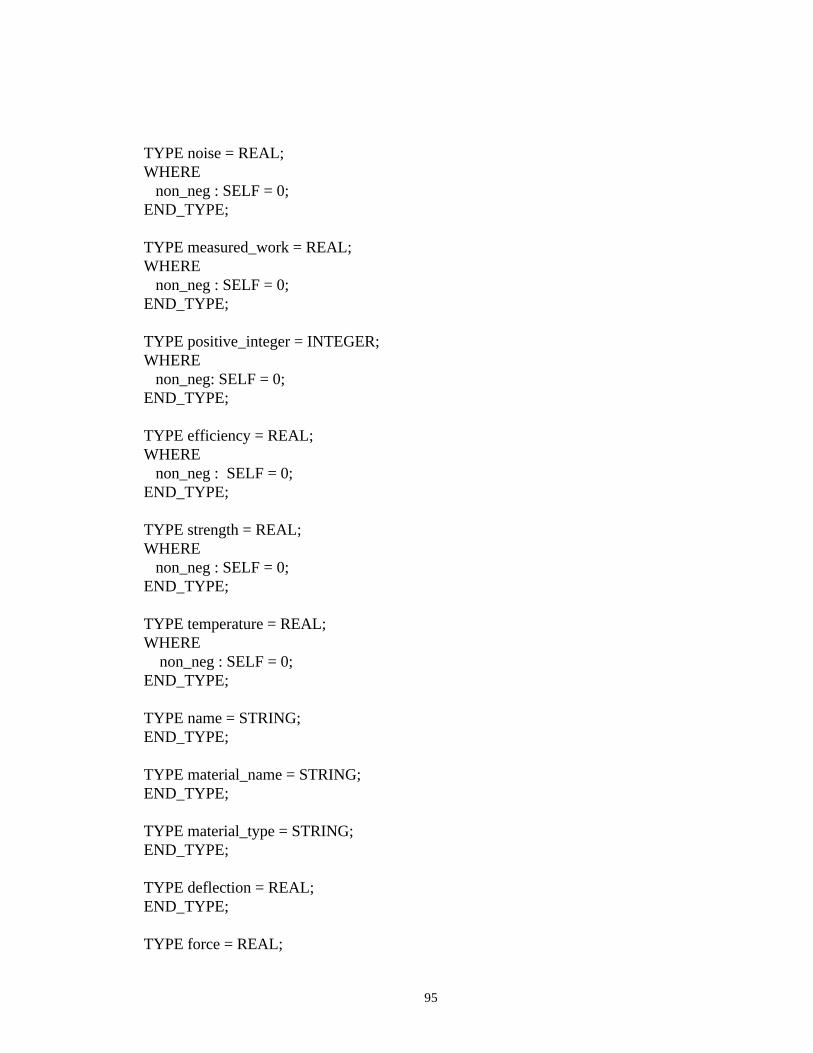
95
TYPE noise = REAL;WHERE non_neg : SELF = 0;END_TYPE;
TYPE measured_work = REAL;WHERE non_neg : SELF = 0;END_TYPE;
TYPE positive_integer = INTEGER;WHERE non_neg: SELF = 0;END_TYPE;
TYPE efficiency = REAL;WHERE non_neg : SELF = 0;END_TYPE;
TYPE strength = REAL;WHERE non_neg : SELF = 0;END_TYPE;
TYPE temperature = REAL;WHERE non_neg : SELF = 0;END_TYPE;
TYPE name = STRING;END_TYPE;
TYPE material_name = STRING;END_TYPE;
TYPE material_type = STRING;END_TYPE;
TYPE deflection = REAL;END_TYPE;
TYPE force = REAL;
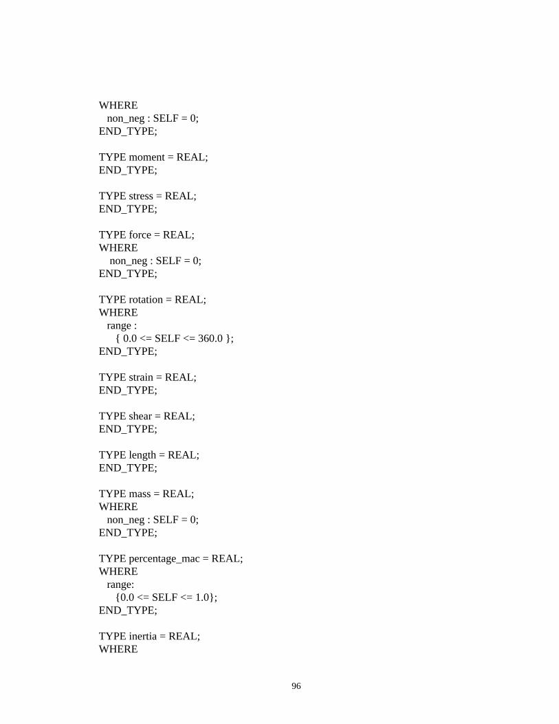
96
WHERE non_neg : SELF = 0;END_TYPE;
TYPE moment = REAL;END_TYPE;
TYPE stress = REAL;END_TYPE;
TYPE force = REAL;WHERE non_neg : SELF = 0;END_TYPE;
TYPE rotation = REAL;WHERE range : { 0.0 <= SELF <= 360.0 };END_TYPE;
TYPE strain = REAL;END_TYPE;
TYPE shear = REAL;END_TYPE;
TYPE length = REAL;END_TYPE;
TYPE mass = REAL;WHERE non_neg : SELF = 0;END_TYPE;
TYPE percentage_mac = REAL;WHERE range: {0.0 <= SELF <= 1.0};END_TYPE;
TYPE inertia = REAL;WHERE
97
non_neg : SELF = 0;END_TYPE;
TYPE derivative_per_degree = REAL;END_TYPE;
TYPE annual_utilization = REAL;WHERE non_neg : SELF = 0;END_TYPE;
TYPE time_hours = REAL;WHERE non_neg : SELF = 0;END_TYPE;
TYPE time_years = REAL;WHERE non_neg : SELF = 0;END_TYPE;
TYPE dollars = REAL;WHERE non_neg : SELF = 0;END_TYPE;
TYPE dollars_per_flight = REAL;WHERE non_neg : SELF = 0;END_TYPE;
TYPE dollars_per_gallon = REAL;WHERE non_neg : SELF = 0;END_TYPE;
TYPE dollars_per_hour = REAL;WHERE non_neg : SELF = 0;END_TYPE;
TYPE dollars_per_flight_cycle = REAL;WHERE
98
non_neg: SELF = 0;END_TYPE;
TYPE dollars_per_month = REAL;WHERE non_neg : SELF = 0;END_TYPE;
TYPE dollars_per_pound = REAL;WHERE non_neg : SELF = 0;END_TYPE;
TYPE deliveries_per_month = REAL;WHERE non_neg : SELF = 0;END_TYPE;
TYPE emission = REAL;WHERE non_neg : SELF = 0;END_TYPE;
TYPE altitude = REAL;WHERE non_neg : SELF = 0;END_TYPE;
TYPE distance_ft = REAL;WHERE non_neg : SELF = 0;END_TYPE;
TYPE distance_nau_miles = REAL;WHERE non_neg : SELF = 0;END_TYPE;
99
TYPE rate_fpm = REAL;WHERE non_neg : SELF = 0;END_TYPE;
TYPE rate_hpfc = REAL;WHERE non_neg : SELF = 0;END_TYPE;
TYPE range_per_pound = REAL;WHERE non_neg : SELF = 0;END_TYPE;
TYPE rate_dps = REAL;WHERE non_neg : SELF = 0;END_TYPE;
TYPE identification_no = STRING;END_TYPE;
TYPE force_per_area = REAL;WHERE non_neg : SELF = 0;END_TYPE;
TYPE energy_per_vol = REAL;WHERE non_neg : SELF = 0;END_TYPE;
TYPE per_temperature = REAL;WHERE non_neg : SELF = 0;END_TYPE;
TYPE percentage_of_hundred = REAL;WHERE non_neg : SELF = 0;END_TYPE;

100
ENTITY ac_configuration; conf_no : identification_no; consists_of : SET [1:?] OF ac_component; has_specific : costs; demonstrates : performance; has_defined : weights; characterized_by : stability_and_control; has_inherent : aerodynamics;UNIQUE un_conf_no : conf_no;END_ENTITY;
ENTITY ac_component; component_id : identification_no; component_name : name; component_type : name; made_up_of : SET [1:?] OF ac_member;UNIQUE un_component_id : component_id;END_ENTITY;
ENTITY ac_member; made_of : materials; member_name : name; member_mat : material_type; member_wt : weight; eps_x : strain; eps_y : strain; eps_z : strain; f_x : force; f_y : force; f_z : force; m_x : moment; m_y : moment; m_z : moment; sig_x : stress; sig_y : stress; sig_z : stress; theta_x : rotation; theta_y : rotation; theta_z : rotation; u_x : deflection;
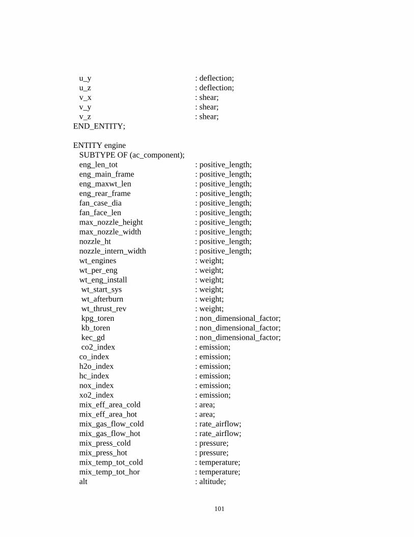
101
u_y : deflection; u_z : deflection; v_x : shear; v_y : shear; v_z : shear;END_ENTITY;
ENTITY engine SUBTYPE OF (ac_component); eng_len_tot : positive_length; eng_main_frame : positive_length; eng_maxwt_len : positive_length; eng_rear_frame : positive_length; fan_case_dia : positive_length; fan_face_len : positive_length; max_nozzle_height : positive_length; max_nozzle_width : positive_length; nozzle_ht : positive_length; nozzle_intern_width : positive_length; wt_engines : weight; wt_per_eng : weight; wt_eng_install : weight; wt_start_sys : weight; wt_afterburn : weight; wt_thrust_rev : weight; kpg_toren : non_dimensional_factor; kb_toren : non_dimensional_factor; kec_gd : non_dimensional_factor; co2_index : emission; co_index : emission; h2o_index : emission; hc_index : emission; nox_index : emission; xo2_index : emission; mix_eff_area_cold : area; mix_eff_area_hot : area; mix_gas_flow_cold : rate_airflow; mix_gas_flow_hot : rate_airflow; mix_press_cold : pressure; mix_press_hot : pressure; mix_temp_tot_cold : temperature; mix_temp_tot_hor : temperature; alt : altitude;
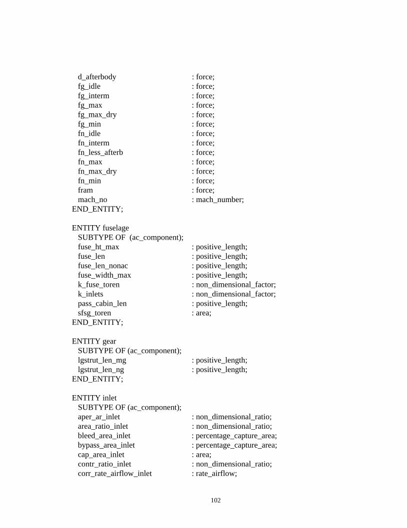
102
d_afterbody : force; fg_idle : force; fg_interm : force; fg_max : force; fg_max_dry : force; fg_min : force; fn_idle : force; fn_interm : force; fn_less_afterb : force; fn_max : force; fn_max_dry : force; fn_min : force; fram : force; mach_no : mach_number;END_ENTITY;
ENTITY fuselage SUBTYPE OF (ac_component); fuse_ht_max : positive_length; fuse_len : positive_length; fuse_len_nonac : positive_length; fuse_width_max : positive_length; k_fuse_toren : non_dimensional_factor; k_inlets : non_dimensional_factor; pass_cabin_len : positive_length; sfsg_toren : area;END_ENTITY;
ENTITY gear SUBTYPE OF (ac_component); lgstrut_len_mg : positive_length; lgstrut_len_ng : positive_length;END_ENTITY;
ENTITY inlet SUBTYPE OF (ac_component); aper_ar_inlet : non_dimensional_ratio; area_ratio_inlet : non_dimensional_ratio; bleed_area_inlet : percentage_capture_area; bypass_area_inlet : percentage_capture_area; cap_area_inlet : area; contr_ratio_inlet : non_dimensional_ratio; corr_rate_airflow_inlet : rate_airflow;
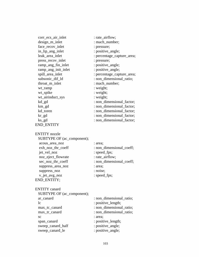
103
corr_ecs_air_inlet : rate_airflow; design_m_inlet : mach_number; face_recov_inlet : pressure; in_lip_ang_inlet : positive_angle; leak_area_inlet : percentage_capture_area; press_recov_inlet : pressure; ramp_ang_fin_inlet : positive_angle; ramp_ang_init_inlet : positive_angle; spill_area_inlet : percentage_capture_area; subsonic_dif_ld : non_dimensional_ratio; throat_m_inlet : mach_number; wt_ramp : weight; wt_spike : weight; wt_airinduct_sys : weight; kd_gd : non_dimensional_factor; km_gd : non_dimensional_factor; kd_toren : non_dimensional_factor; kr_gd : non_dimensional_factor; ks_gd : non_dimensional_factor;END_ENTITY
ENTITY nozzle SUBTYPE OF (ac_component); acous_area_noz : area; exh_noz_thr_coeff : non_dimensional_coeff; jet_vel_noz : speed_fps; noz_eject_flowrate : rate_airflow; sec_noz_thr_coeff : non_dimensional_coeff; suppress_area_noz : area; suppress_noz : noise; v_jet_avg_noz : speed_fps;END_ENTITY;
ENTITY canard SUBTYPE OF (ac_component); ar_canard : non_dimensional_ratio; lc : positive_length; max_tc_canard : non_dimensional_ratio; max_tr_canard : non_dimensional_ratio; sc : area; span_canard : positive_length; sweep_canard_half : positive_angle; sweep_canard_le : positive_angle;

104
sweep_canard_quar : positive_angle; taper_canard : non_dimensional_ratio; thick_ratio_canard : non_dimensional_ratio;END_ENTITY;
ENTITY horizontal SUBTYPE OF (ac_component); ar_horiz : non_dimensional_ratio; kh : non_dimensional_factor; lh : positive_length; max_tc_horiz : non_dimensional_ratio; max_tr_horiz : non_dimensional_ratio; sh : area; span_horiz : positive_length; sweep_horiz_half : positive_angle; sweep_horiz_le : positive_angle; sweep_horiz_quar : positive_angle; taper_horiz : non_dimensional_ratio; thick_ratio_horiz : non_dimensional_ratio; vh : non_dimensional_ratio; zh : positive_length;END_ENTITY;
ENTITY vertical SUBTYPE OF (ac_component); ar_vert : non_dimensional_ratio; kv : non_dimensional_factor; lv : positive_length; max_tc_vert : non_dimensional_ratio; max_tr_vert : non_dimensional_ratio; span_vert : positive_length; sv : area; sweep_vert_half : positive_angle; sweep_vert_le : positive_angle; sweep_vert_quar : positive_angle;
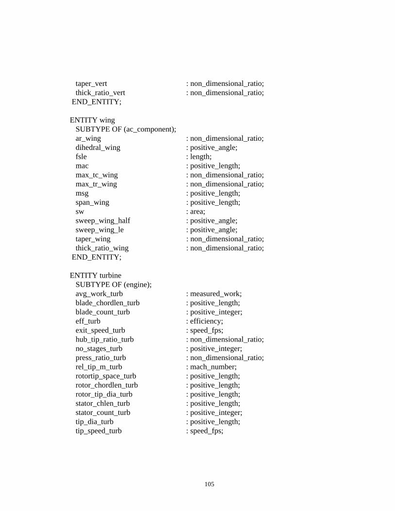
105
taper_vert : non_dimensional_ratio; thick_ratio_vert : non_dimensional_ratio; END_ENTITY;
ENTITY wing SUBTYPE OF (ac_component); ar_wing : non_dimensional_ratio; dihedral_wing : positive_angle; fsle : length; mac : positive_length; max_tc_wing : non_dimensional_ratio; max_tr_wing : non_dimensional_ratio; msg : positive_length; span_wing : positive_length; sw : area; sweep_wing_half : positive_angle; sweep_wing_le : positive_angle; taper_wing : non_dimensional_ratio; thick_ratio_wing : non_dimensional_ratio; END_ENTITY;
ENTITY turbine SUBTYPE OF (engine); avg_work_turb : measured_work; blade_chordlen_turb : positive_length; blade_count_turb : positive_integer; eff_turb : efficiency; exit_speed_turb : speed_fps; hub_tip_ratio_turb : non_dimensional_ratio; no_stages_turb : positive_integer; press_ratio_turb : non_dimensional_ratio; rel_tip_m_turb : mach_number; rotortip_space_turb : positive_length; rotor_chordlen_turb : positive_length; rotor_tip_dia_turb : positive_length; stator_chlen_turb : positive_length; stator_count_turb : positive_integer; tip_dia_turb : positive_length; tip_speed_turb : speed_fps;
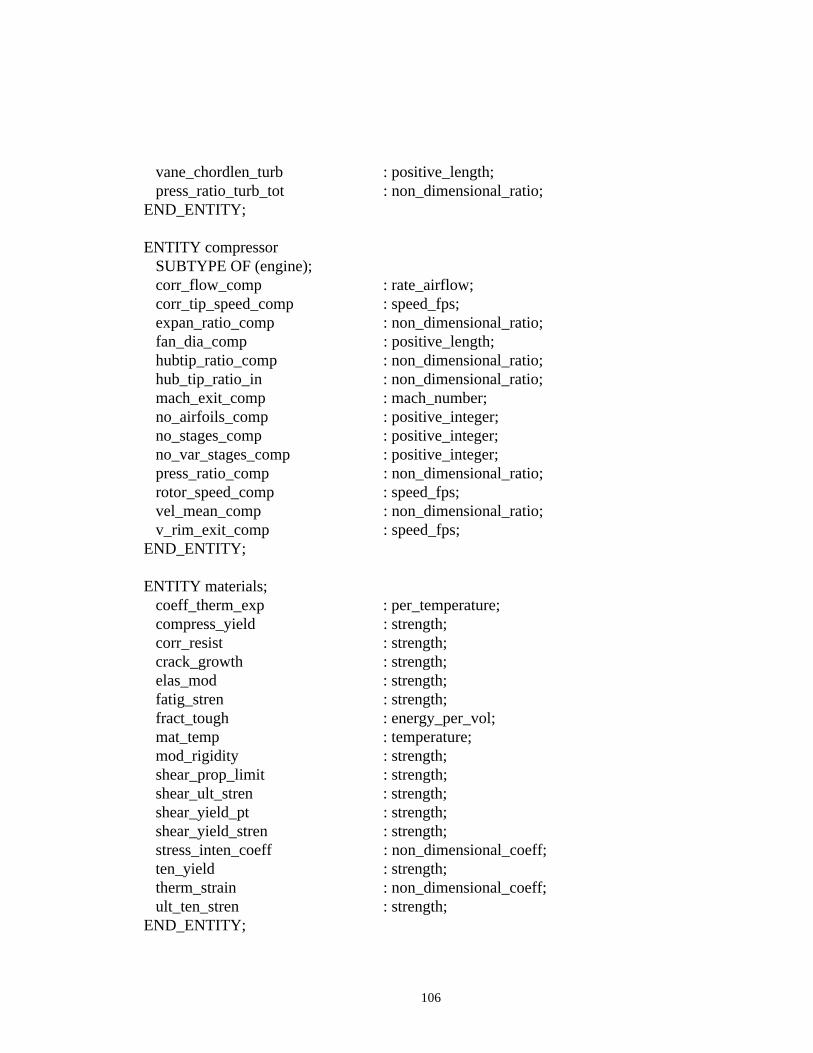
106
vane_chordlen_turb : positive_length; press_ratio_turb_tot : non_dimensional_ratio;END_ENTITY;
ENTITY compressor SUBTYPE OF (engine); corr_flow_comp : rate_airflow; corr_tip_speed_comp : speed_fps; expan_ratio_comp : non_dimensional_ratio; fan_dia_comp : positive_length; hubtip_ratio_comp : non_dimensional_ratio; hub_tip_ratio_in : non_dimensional_ratio; mach_exit_comp : mach_number; no_airfoils_comp : positive_integer; no_stages_comp : positive_integer; no_var_stages_comp : positive_integer; press_ratio_comp : non_dimensional_ratio; rotor_speed_comp : speed_fps; vel_mean_comp : non_dimensional_ratio; v_rim_exit_comp : speed_fps;END_ENTITY;
ENTITY materials; coeff_therm_exp : per_temperature; compress_yield : strength; corr_resist : strength; crack_growth : strength; elas_mod : strength; fatig_stren : strength; fract_tough : energy_per_vol; mat_temp : temperature; mod_rigidity : strength; shear_prop_limit : strength; shear_ult_stren : strength; shear_yield_pt : strength; shear_yield_stren : strength; stress_inten_coeff : non_dimensional_coeff; ten_yield : strength; therm_strain : non_dimensional_coeff; ult_ten_stren : strength;END_ENTITY;
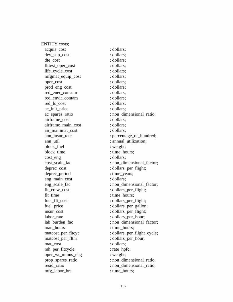
107
ENTITY costs; acquis_cost : dollars; dev_sup_cost : dollars; dte_cost : dollars; flttest_oper_cost : dollars; life_cycle_cost : dollars; mfgmat_equip_cost : dollars; oper_cost : dollars; prod_eng_cost : dollars; red_ener_consum : dollars; red_envir_contam : dollars; red_lc_cost : dollars; ac_init_price : dollars; ac_spares_ratio : non_dimensional_ratio; airframe_cost : dollars; airframe_main_cost : dollars; air_mainmat_cost : dollars; ann_insur_rate : percentage_of_hundred; ann_util : annual_utilization; block_fuel : weight; block_time : time_hours; cost_eng : dollars; cost_scale_fac : non_dimensional_factor; deprec_cost : dollars_per_flight; deprec_period : time_years; eng_main_cost : dollars; eng_scale_fac : non_dimensional_factor; flt_crew_cost : dollars_per_flight; flt_time : time_hours; fuel_flt_cost : dollars_per_flight; fuel_price : dollars_per_gallon; insur_cost : dollars_per_flight; labor_rate : dollars_per_hour; lab_burden_fac : non_dimensional_factor; man_hours : time_hours; matcost_per_fltcyc : dollars_per_flight_cycle; matcost_per_flthr : dollars_per_hour; mat_cost : dollars; mh_per_fltcycle : rate_hpfc; oper_wt_minus_eng : weight; prop_spares_ratio : non_dimensional_ratio; resid_ratio : non_dimensional_ratio; mfg_labor_hrs : time_hours;
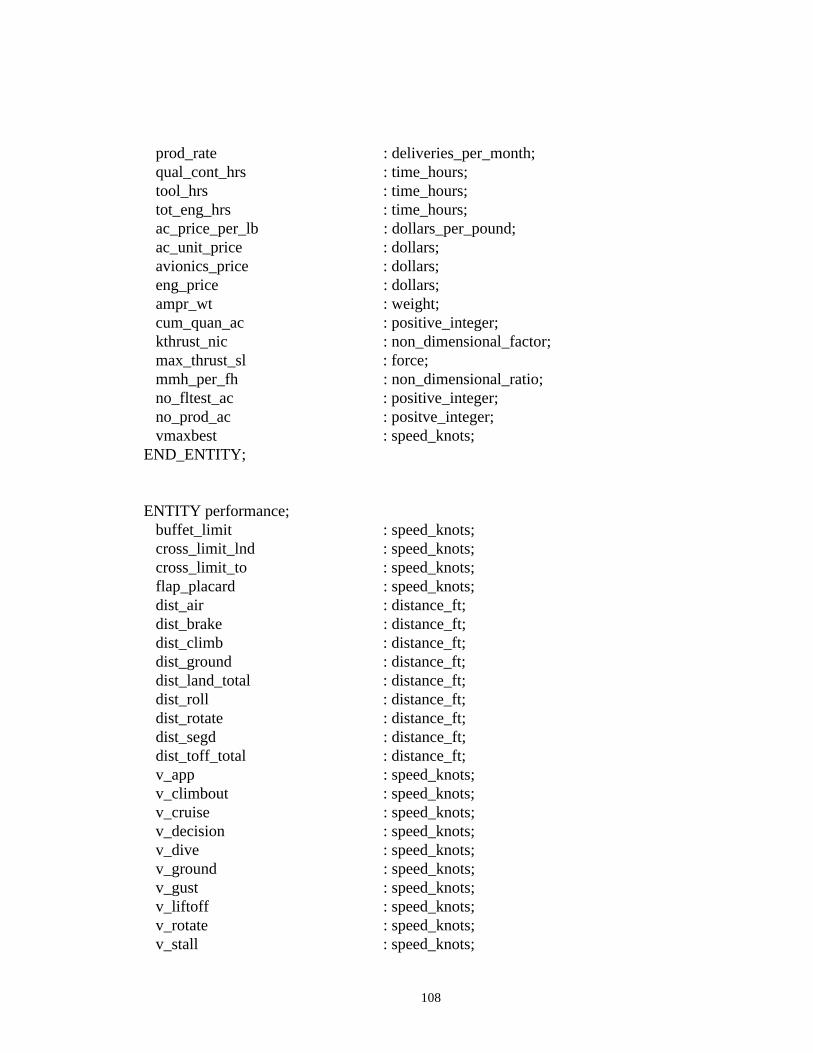
108
prod_rate : deliveries_per_month; qual_cont_hrs : time_hours; tool_hrs : time_hours; tot_eng_hrs : time_hours; ac_price_per_lb : dollars_per_pound; ac_unit_price : dollars; avionics_price : dollars; eng_price : dollars; ampr_wt : weight; cum_quan_ac : positive_integer; kthrust_nic : non_dimensional_factor; max_thrust_sl : force; mmh_per_fh : non_dimensional_ratio; no_fltest_ac : positive_integer; no_prod_ac : positve_integer; vmaxbest : speed_knots;END_ENTITY;
ENTITY performance; buffet_limit : speed_knots; cross_limit_lnd : speed_knots; cross_limit_to : speed_knots; flap_placard : speed_knots; dist_air : distance_ft; dist_brake : distance_ft; dist_climb : distance_ft; dist_ground : distance_ft; dist_land_total : distance_ft; dist_roll : distance_ft; dist_rotate : distance_ft; dist_segd : distance_ft; dist_toff_total : distance_ft; v_app : speed_knots; v_climbout : speed_knots; v_cruise : speed_knots; v_decision : speed_knots; v_dive : speed_knots; v_ground : speed_knots; v_gust : speed_knots; v_liftoff : speed_knots; v_rotate : speed_knots; v_stall : speed_knots;
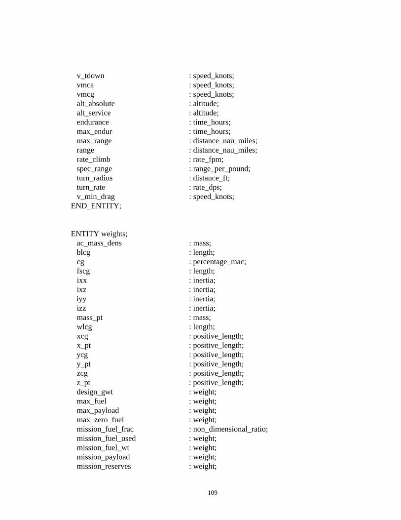
109
v_tdown : speed_knots; vmca : speed_knots; vmcg : speed_knots; alt_absolute : altitude; alt_service : altitude; endurance : time_hours; max_endur : time_hours; max_range : distance_nau_miles; range : distance_nau_miles; rate_climb : rate_fpm; spec_range : range_per_pound; turn_radius : distance_ft; turn_rate : rate_dps; v_min_drag : speed_knots;END_ENTITY;
ENTITY weights; ac_mass_dens : mass; blcg : length; cg : percentage_mac; fscg : length; ixx : inertia; ixz : inertia; iyy : inertia; izz : inertia; mass_pt : mass; wlcg : length; xcg : positive_length; x_pt : positive_length; ycg : positive_length; y_pt : positive_length; zcg : positive_length; z_pt : positive_length; design_gwt : weight; max_fuel : weight; max_payload : weight; max_zero_fuel : weight; mission_fuel_frac : non_dimensional_ratio; mission_fuel_used : weight; mission_fuel_wt : weight; mission_payload : weight; mission_reserves : weight;
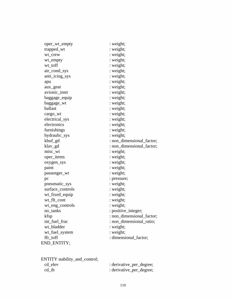
110
oper_wt_empty : weight; trapped_wt : weight; wt_crew : weight; wt_empty : weight; wt_toff : weight; air_cond_sys : weight; anti_icing_sys : weight; apu : weight; aux_gear : weight; avionic_instr : weight; baggage_equip : weight; baggage_wt : weight; ballast : weight; cargo_wt : weight; electrical_sys : weight; electronics : weight; furnishings : weight; hydraulic_sys : weight; kbuf_gd : non_dimensional_factor; klav_gd : non_dimensional_factor; misc_wt : weight; oper_items : weight; oxygen_sys : weight; paint : weight; passenger_wt : weight; pc : pressure; pneumatic_sys : weight; surface_controls : weight; wt_fixed_equip : weight; wt_flt_cont : weight; wt_eng_controls : weight; no_tanks : positive_integer; kfsp : non_dimensional_factor; int_fuel_frac : non_dimensional_ratio; wt_bladder : weight; wt_fuel_system : weight; ffr_toff : dimensional_factor;END_ENTITY;
ENTITY stability_and_control; cd_elev : derivative_per_degree; cd_ih : derivative_per_degree;

111
cl_elev : derivative_per_degree; cl_ih : derivative_per_degree; cm_elev : derivative_per_degree; cm_ih : derivative_per_degree; cn_ail : derivative_per_degree; cr_rud : derivative_per_degree; cy_ail : derivative_per_degree; cy_rud : derivative_per_degree; cn_rud : derivative_per_degree; cr_ail : derivative_per_degree; cd_alpha_wb : derivative_per_degree; cl_alpha_wb : derivative_per_degree; cm_alpha_wb : derivative_per_degree; cnt_beta : non_dimensional_coeff; ctm_alpha : non_dimensional_coeff; ctm_u : non_dimensional_coeff; ctx_alpha : non_dimensional_coeff; ctx_u : non_dimensional_coeff; ctz_alpha : non_dimensional_coeff; ctz_u : non_dimensional_coeff; cn_p : non_dimensional_coeff; cn_r : non_dimensional_coeff; cr_p : non_dimensional_coeff; cr_r : non_dimensional_coeff; cy_p : non_dimensional_coeff; cy_r : non_dimensional_coeff; cd_q : non_dimensional_coeff; cl_q : non_dimensional_coeff; cm_q : non_dimensional_coeff; cmo : non_dimensional_coeff; cno : non_dimensional_coeff; cro : non_dimensional_coeff; cyo : non_dimensional_coeff; cd_alpha : derivative_per_degree; cd_alpha_dot : non_dimensional_coeff; cl_alpha : derivative_per_degree; cl_alpha_dot : non_dimensional_coeff; cm_alpha : derivative_per_degree; cm_alpha_dot : non_dimensional_coeff; cn_beta : derivative_per_degree; cn_beta_dot : non_dimensional_coeff; cr_beta : derivative_per_degree; cr_beta_dot : non_dimensional_coeff;
112
cy_beta : derivative_per_degree; cy_beta_dot : non_dimensional_coeff;END_ENTITY;
ENTITY aerodynamics; cl_canard : non_dimensional_coeff; cl_horiz : non_dimensional_coeff; cl_wb : non_dimensional_coeff; cl_wbt : non_dimensional_coeff; alpha : positive_angle; flap : positive_angle; cd_compress : non_dimensional_coeff; cd_induced : non_dimensional_coeff; cd_interference : non_dimensional_coeff; cd_protub : non_dimensional_coeff; cd_skin_fric : non_dimensional_coeff; cd_trim : non_dimensional_coeff;END_ENTITY;
END_SCHEMA;
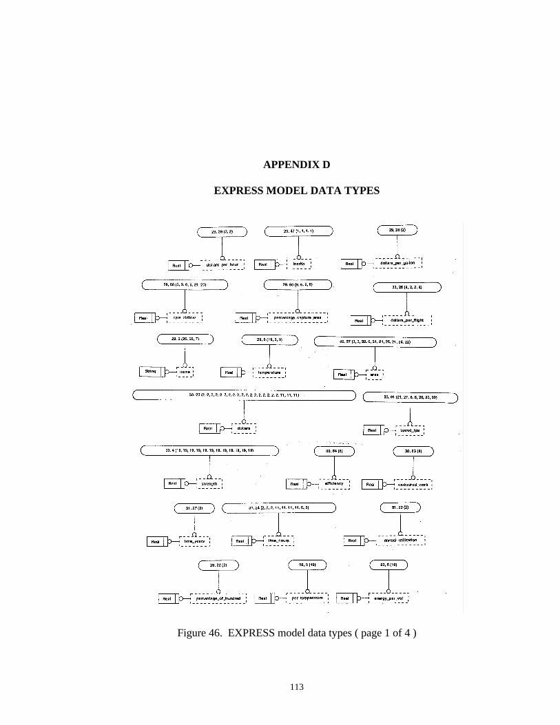
113
APPENDIX D
EXPRESS MODEL DATA TYPES
Figure 46. EXPRESS model data types ( page 1 of 4 )
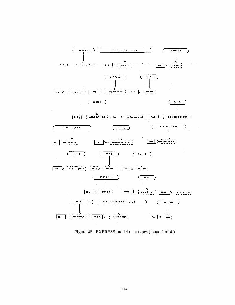
114
Figure 46. EXPRESS model data types ( page 2 of 4 )
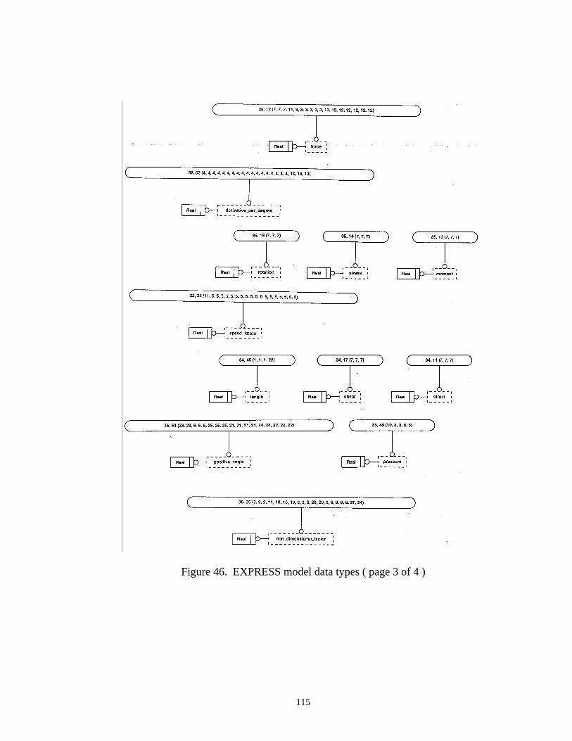
115
Figure 46. EXPRESS model data types ( page 3 of 4 )
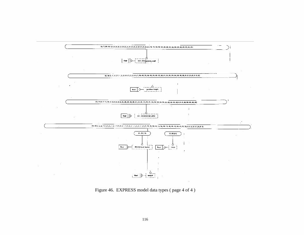
116
Figure 46. EXPRESS model data types ( page 4 of 4 )
117
REFERENCES
1. Fulton, R.E. and Chadha, B., Engineering Data Management, Course Notes, ME 6754, Georgia Tech Publishing, 1994.
2. Schrage, D.P., et. al., "New Approaches to HSCT Multidisciplinary Design and Optimization", Georgia Tech Proposal in Response to NASA Research Announcement
93-LaRC-1, 29 July 1993.
3. Kroo, L., and Takai, M., "A Quasi-Procedural, Knowledge-Based System for Aircraft Design", AIAA/AHS/ASEE Aircraft Design, Systems and Operations Meeting, Atlanta, GA, Sept. 1988.
4. Sobieski, J., "Multidisciplinary Optimization for Engineering Systems: Achievementsand Potential", NASA TM 101566, March 1989.
5. Ashcom, J.R. and Bsharah, F., "Engineering Data Requirements Using an Information Model".
6. Schenck, D.A. and Wilson, P.R., Information Modeling: The EXPRESS Way, OxfordUniversity Press, 1994.
7. Peak, R.S., "An Overview of STEP", Presentation to GT CALS Research Group, 3 December 1991.
8. Roskam, Jan, Airplane Design, Part I: Preliminary Sizing of Airplanes, Roskam Aviation and Engineering Corporation, 1985.
9. Roskam, Jan, Airplane Design, Part V: Component Weight Estimation, Roskam Aviation and Engineering Corporation, 1985.
10. Nicolai, Leland M., Fundamentals of Aircraft Design, METS, Inc., 1975, Revised 1984.
11. Roskam, Jan, "Understanding Cost", Roskam Aviation and Engineering Corporation, 1986.
12. Lan, Chuan-Tau Edward and Roskam, Jan, Airplane Aerodynamics and Performance, Roskam Aviation and Engineering Corporation, 1980.
118
13. Roskam, Jan, Airplane Flight Dynamics and Automatic Flight Controls, Part I, Roskam Aviation and Engineering Corporation, 1979.
14. Cattell, R.G.G., Object Data Management: Object-Oriented and Extended RelationalDatabase Systems, Addison-Wesley Publishing Company, 1993.
15. Maier, “Making Database Systems Fast Enough for CAD Applications”, TechnicalReport, Oregon Graduate Center, Beaverton, Oregon, 1988.
16. Hardwick, R., “Why ROSE is Fast: Five Optimizations in the Design of anExperimental Database System for CAD Applications”, in Proceedings of the ACMSIGMOD Conference, San Francisco, California, 1987.
17. Cattell, R.G.G., Skeen, J., “Object Operations Benchmark”, ACM Transactions onDatabase Systems ( in press). 1991-92. Derivative paper in [Gray 1991].
18. Gray, J. N., The Benchmark Handbook for Database and Transaction ProcessingSystems, Morgan-Kaufmann, 1991.
19. Eastman, Charles M., Fereshetian, Nirva, “Information models for use in productdesign: a comparison”, Computer_Aided Design Volume 26, Number 7, July 1994.
20. Kemper, Alfons Heinrich, Object-oriented database management: applications inengineering and computer science, Prentice-Hall, Inc., 1994.
21. Date, C. J. , An Introduction to Database Systems, Addison-Wesley PublishingCompany, 1995.
22. Codd, E. F., “Further Normalization of the Data Base Relational Model.” In dataBase Systems, Courant Computer Science Symposia Series 6, Prentice-Hall, 1972.