data modeling isys 464. database design process conceptual database design: –the process of...
Post on 21-Dec-2015
219 views
TRANSCRIPT

Data Modeling
ISYS 464

Database Design Process
• Conceptual database design:– The process of creating a data model independent of
implementation details such as the target database model and physical considerations.
• Logical database design:– The process of designing database logical structure
based on a specific database model (such as relational model), but independent of a particular DBMS and physical considerations.
• Physical database design:– The process of implementing the database on a
secondary storage.

Requirements Collection and Analysis
• The process of collecting and analyzing information about the organization that is to be supported by the database system, and use this information to identify the requirements for the new system.

User Views
• A user view defines what is required of a database system in terms of the data to be held and transactions to be performed on the data from the perspective of a particular job role or enterprise application area.
• Identifying user views helps to ensure that no major users of the database are forgotten when developing the requirements for the new database system.

Example of User’s View
• Reports
• Forms– Shopping cart
• Documents

Fact-Finding Techniques
• Examining documentation– Defining problem and need for database:
• Internal memos, minutes of meetings, documents that describe the problem, organizational chart
– Describe the current system:• Various types of flowcharts and diagrams, data dictionary,
database system design, program documentation
• Interviewing• Observing the enterprise in operation• Questionnaires
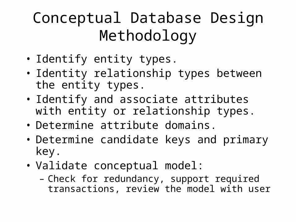
Conceptual Database Design Methodology
• Identify entity types.• Identity relationship types between the entity
types.• Identify and associate attributes with entity or
relationship types.• Determine attribute domains.• Determine candidate keys and primary key.• Validate conceptual model:
– Check for redundancy, support required transactions, review the model with user

Entity-Relationship Diagram
• ER modeling is a top-down approach to database design that begins by identifying the entities and relationships between entities that must be represented in the model.– Relative ease of use.
– Widespread CASE tool support.
– The belief that entities and relationships are natural modeling concepts in the real world.
– Classifying things according to their various kinds.

ERD Models Entities and Business Rules
• Example:– A customer may submit any number of orders.
However, each order must be submitted by exactly one customer.
– A student may register for a section of a course only if he or she has successfully completed the prerequisites for that course.

Entities
• An entity is a person, place, object, event, or concept in the user environment about which the organization wishes to maintain data.– Person: Employee, Student, patient– Place: Warehouse, Store– Object: Product, Machine.– Event: Registration, Sale, Renewal– Concept: Account, Course
• Physical existence:• Customer, student, product, etc.
• Conceptual existence:• Bank accounts, sale

Entity Type
• A collection of entities that share common properties or characteristics.
• An entity type represents a collection of entities.
• In an ERD, it is given a singular name.
• Diagrammatic representation:– A rectangle labeled with the name of the entity

Entity Instance
• An entity instance is a single occurrence of an entity type:– Student entity: SID, Sname, Major– Two instances of Student entity type:
• S1, Peter, Bus
• S5, Paul, Sci

Relationship Type
• Relationship: Interaction between entity types.– It is an association representing an interaction
among the instances of one or more entity types that is interest to the organization.
• It has a verb phrase name:– Faculty teach Course, Faculty advise Student– Customer open Account, Customer purchase
Product.
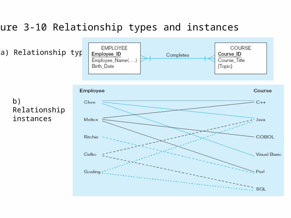
Figure 3-10 Relationship types and instances
a) Relationship type
b) Relationship instances

Degree of a Relationship
The number of participating entity types in a relationship.
– Unary (recursive)– Binary– Ternary

Three kinds of Binary Relationship
• 1:1
• 1:M
• M:M

M:M Relationship
Peter
Paul
John
Woody
Alan
Mary
Linda
Nancy
Mia
Pia
A boy may date 0, 1, or many girls.
A girl may date 0, 1, or many boys.
Note: “Many boys date many girls” is not a correct interpretation.
Boy Girl

1:1 Relationship
Peter
Paul
John
Woody
Alan
Mary
Linda
Nancy
Mia
Pia
A man may marry 0 or 1 woman.
A woman may marry 0 or 1 man.
Husband Wife

1:M Relationship
Peter
Paul
John
Woody
Alan
MaryBrianLindaAron
NancyRonald
MiaPia
A father has 1 or many children.
A child has 1 father.
Father Child

Cardinality Constraint
• A cardinality constraint specifies the number of instances of entity type A that can (or must) be associated with each instance of entity type B.
• Participation constraint– Full participation (Mandatory)– Partial participation (Optional)
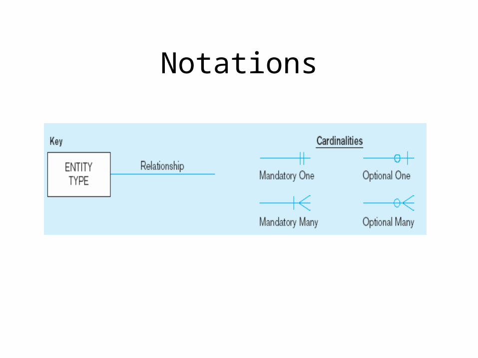
Notations
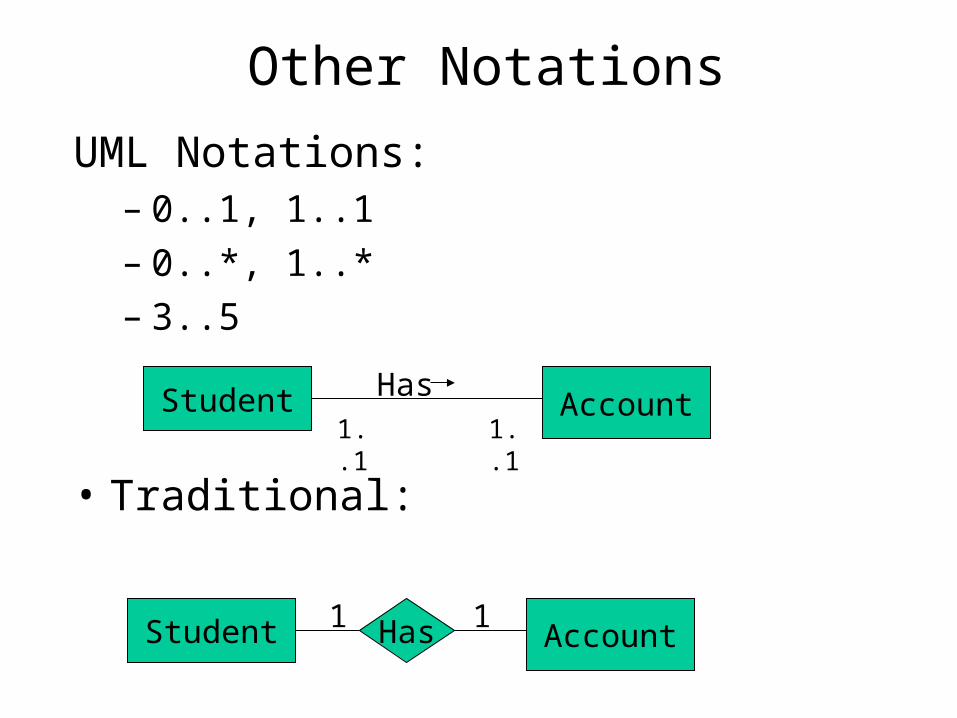
Other Notations
UML Notations:– 0..1, 1..1– 0..*, 1..*– 3..5
• Traditional:
Student AccountHas1 1
Student AccountHas
1..11..1

1:1 Relationship
• Examples:– Husband, Wife– State, State Governor– Order, Invoice

1:M Relationship
• Examples:– Father, Child– Department, Employee– Customer, Order

M:M Relationship
• Examples:– Boy friend, Girl friend– Bank customer, Bank account– Student, Student organization
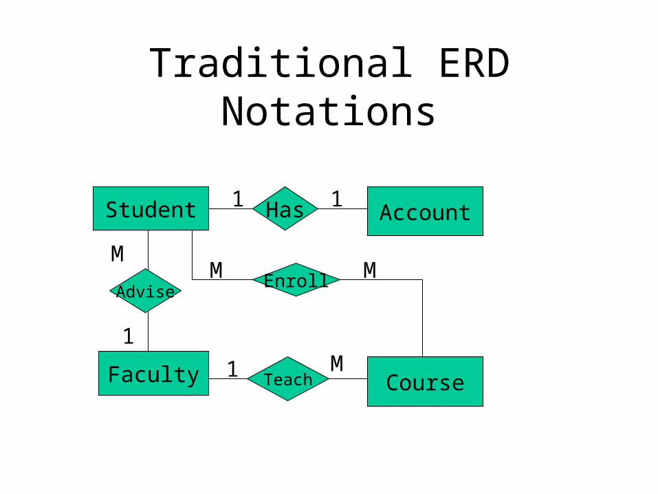
Traditional ERD Notations
Student Account
Faculty Course
Has1 1
EnrollM MAdvise
M
1
TeachM1
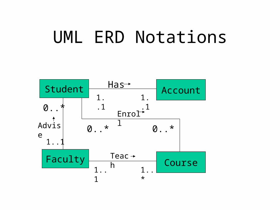
UML ERD Notations
Student Account
Faculty Course
Has1..11..1
Teach
1..*1..1
Enroll
0..* 0..*Advise
0..*
1..1
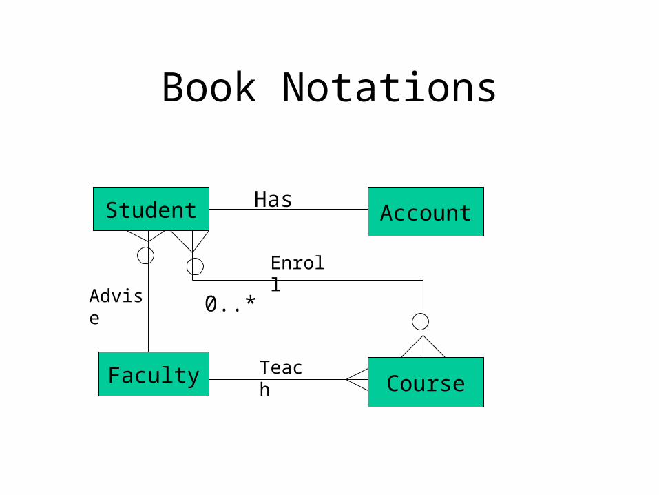
Book Notations
Student Account
Faculty Course
Has
Teach
Enroll
0..*Advise
Other Examples
• A database to record visitors and web pages they view.
• An online shopping website database to record customers, orders (shopping carts) and products purchased by customers.
• An auction database to record sellers and the items they sell, buyers and the items they purchase.
• University email account database to record students, email accounts and email messages.
Recursive Relationship
• A relationship type where the same entity type participates more than once in different roles.
• Examples:– Employee – Supervise -- Employee– Student -- Tutor– Student– Faculty – Evaluate -- Faculty
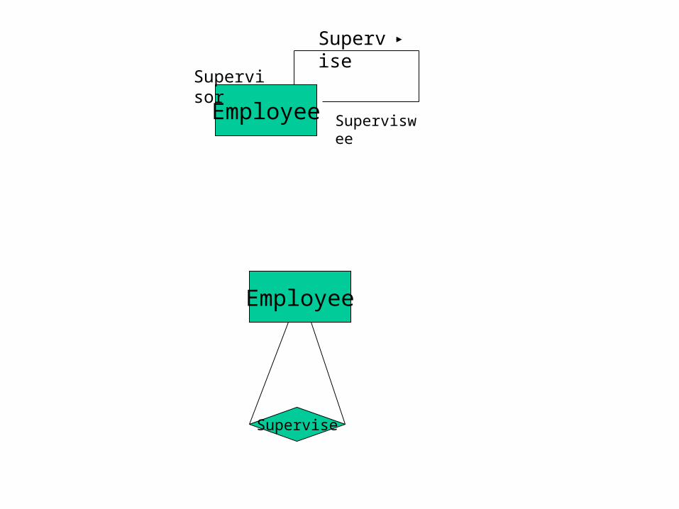
Employee
Supervise
Supervisor
Superviswee
Employee
Supervise

Attributes• Properties of an entity or a relationship.• Simple and composite attributes
– Address:Street address, City, State, ZipCode– Street Address: Number, Street, Apt#
• Single-valued and multi-valued attributes– Student’s Major attribute– Faculty’s DegreeEarned attribute– Vehicle’s Color attribute– Others: PhoneNumber, EmailAddress
• Derived attributes• Keys
– Candidate key, primary key, composite key

UML Notations
StudentSID {PK}Sname Fname LnameAddress Street City State ZipPhone[1..3]SexDateOfBirth/Age
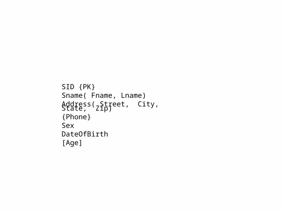
SID {PK}Sname( Fname, Lname)Address( Street, City, State, Zip){Phone}SexDateOfBirth[Age]
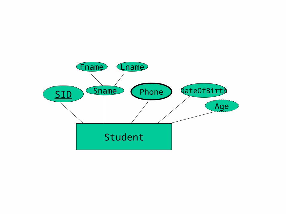
Student
SID Sname
Fname Lname
Phone DateOfBirth
Age
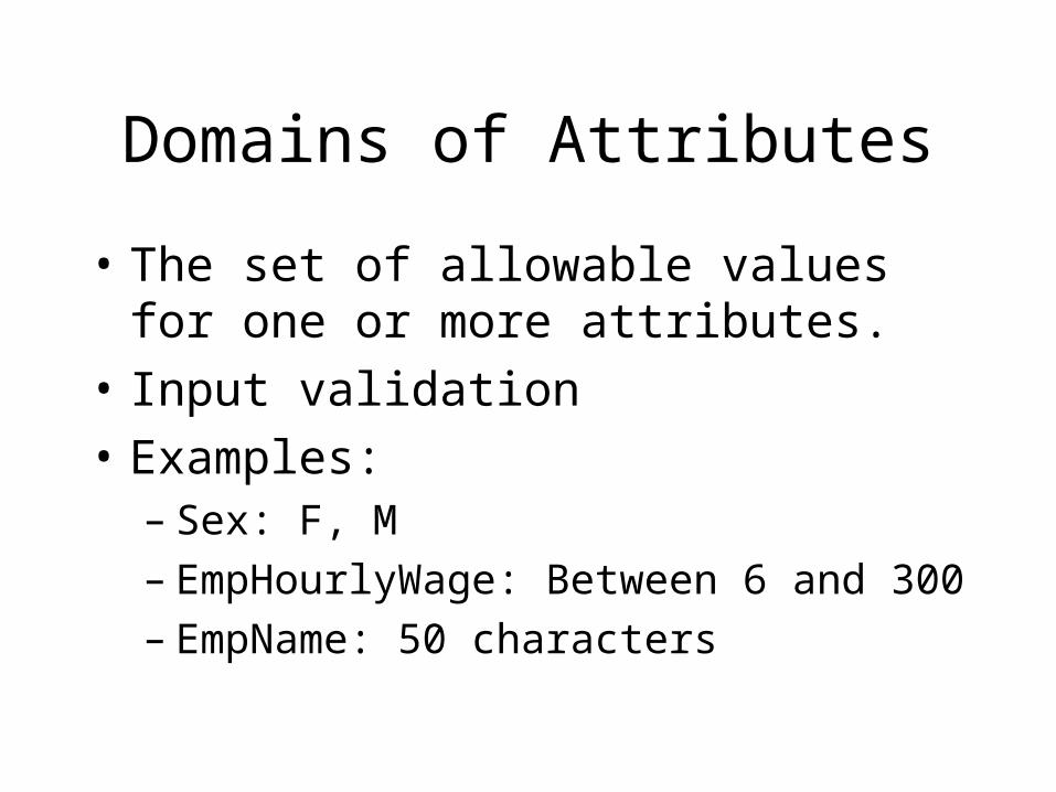
Domains of Attributes
• The set of allowable values for one or more attributes.
• Input validation
• Examples:– Sex: F, M– EmpHourlyWage: Between 6 and 300– EmpName: 50 characters
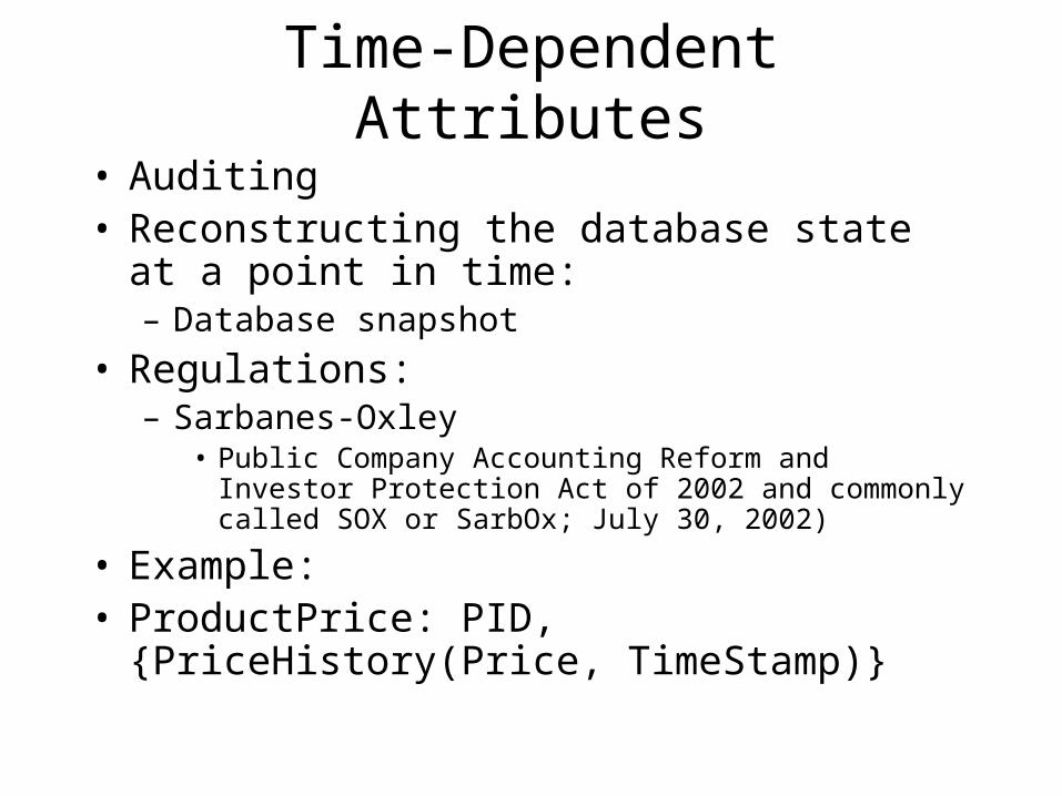
Time-Dependent Attributes
• Auditing• Reconstructing the database state at a point in
time:– Database snapshot
• Regulations:– Sarbanes-Oxley
• Public Company Accounting Reform and Investor Protection Act of 2002 and commonly called SOX or SarbOx; July 30, 2002)
• Example:• ProductPrice: PID, {PriceHistory(Price,
TimeStamp)}

Attributes on Relationship Online Shopping Cart
Customer ShoppingCart
Product
Has
Has
1 M
M
M
CID CnameAddr CartID Date
PIDPname
Price

Online Shopping Cart
Customer ShoppingCart
Product
Has
Has
1 M
M
M
CID CnameAddr CartID Date
Qty
PIDPname
Price
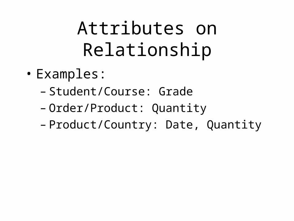
Attributes on Relationship
• Examples:– Student/Course: Grade– Order/Product: Quantity– Product/Country: Date, Quantity
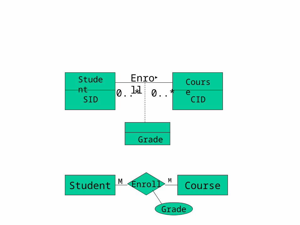
Enroll
0..*0..*
Student
SID
Course
CID
Grade
Student CourseEnrollMM
Grade

N-ary Relationship
• Doctor – Patient – Ailment
• Police – Crimal – Crime
• AirCraft – Bomb – Target
• Note: There is no deterministic relationship (1:1 or 1:M) between any two of these entities.
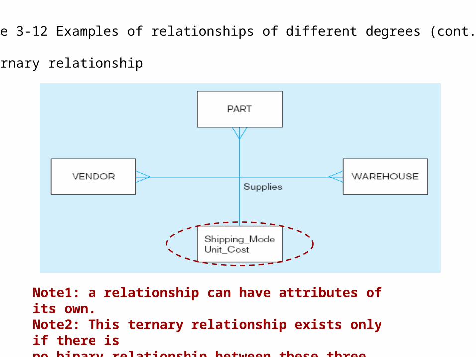
Figure 3-12 Examples of relationships of different degrees (cont.)
c) Ternary relationship
Note1: a relationship can have attributes of its own.Note2: This ternary relationship exists only if there is no binary relationship between these three entities.
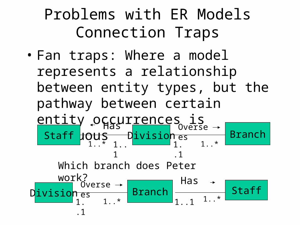
Problems with ER ModelsConnection Traps
• Fan traps: Where a model represents a relationship between entity types, but the pathway between certain entity occurrences is ambiguous
Staff Division BranchHas Oversees
1..*1..1 1..11..*
Which branch does Peter work?
Division BranchOversees
1..*1..1Staff
Has
1..*1..1

Chasm Traps
• Where a model suggests the existence of a relationship between entity types, but the pathway does not exist between certain entity occurrences.
Branch Staff1..*1..1
Has PropertyForRent
Oversees
0..1 0..*
Which properties are available at each branch?

Entity Type not System User or Organizational Unit
Report MeSendTo
MyCompany DepartmentHas
Note: An entity type represents a collection of entities.
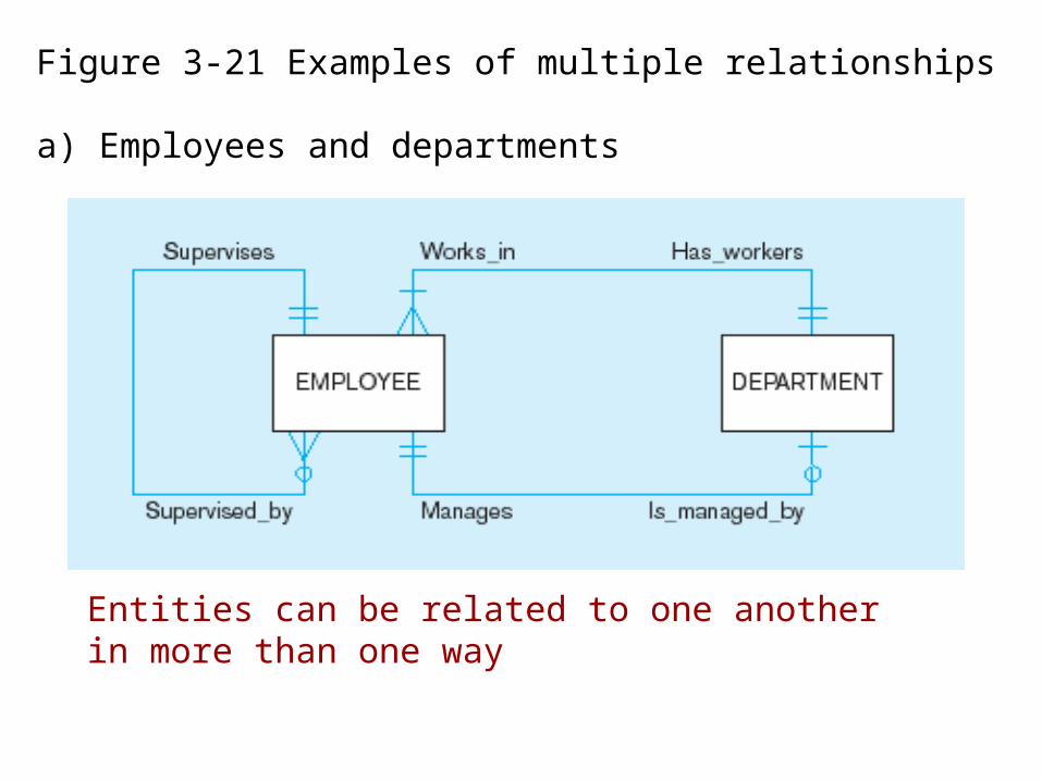
Entities can be related to one another in more than one way
Figure 3-21 Examples of multiple relationships
a) Employees and departments