image fusion elements brainlab · intended use for image fusion brainlab elements image fusion is...
TRANSCRIPT

BRAINLAB ELEMENTSIMAGE FUSIONVersion 4.0
Software User GuideRevision 1.0Copyright 2018, Brainlab AG Germany. All rights reserved.

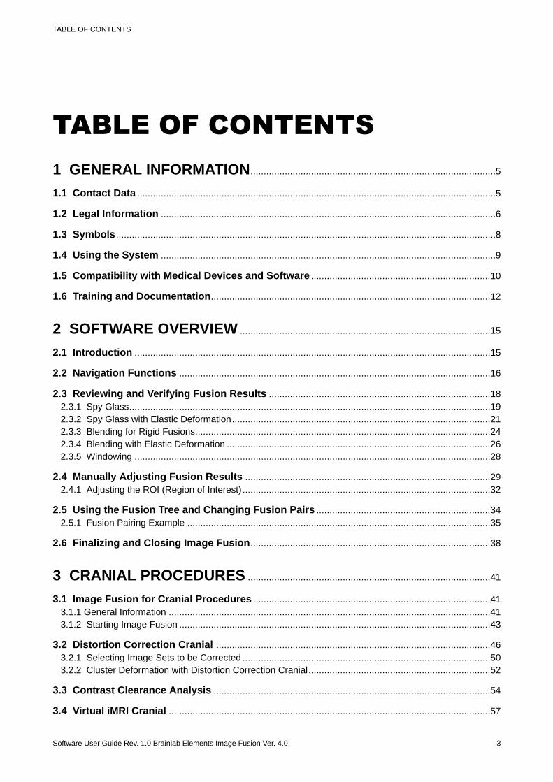
TABLE OF CONTENTS1 GENERAL INFORMATION.............................................................................................5
1.1 Contact Data ........................................................................................................................................5
1.2 Legal Information ...............................................................................................................................6
1.3 Symbols................................................................................................................................................8
1.4 Using the System ...............................................................................................................................9
1.5 Compatibility with Medical Devices and Software ....................................................................10
1.6 Training and Documentation..........................................................................................................12
2 SOFTWARE OVERVIEW ...............................................................................................15
2.1 Introduction .......................................................................................................................................15
2.2 Navigation Functions ......................................................................................................................16
2.3 Reviewing and Verifying Fusion Results ....................................................................................182.3.1 Spy Glass.........................................................................................................................................192.3.2 Spy Glass with Elastic Deformation..................................................................................................212.3.3 Blending for Rigid Fusions................................................................................................................242.3.4 Blending with Elastic Deformation ....................................................................................................262.3.5 Windowing .......................................................................................................................................28
2.4 Manually Adjusting Fusion Results .............................................................................................292.4.1 Adjusting the ROI (Region of Interest) ..............................................................................................32
2.5 Using the Fusion Tree and Changing Fusion Pairs ..................................................................342.5.1 Fusion Pairing Example ...................................................................................................................35
2.6 Finalizing and Closing Image Fusion...........................................................................................38
3 CRANIAL PROCEDURES ............................................................................................41
3.1 Image Fusion for Cranial Procedures ..........................................................................................413.1.1 General Information ..........................................................................................................................413.1.2 Starting Image Fusion ......................................................................................................................43
3.2 Distortion Correction Cranial ........................................................................................................463.2.1 Selecting Image Sets to be Corrected ..............................................................................................503.2.2 Cluster Deformation with Distortion Correction Cranial.....................................................................52
3.3 Contrast Clearance Analysis .........................................................................................................54
3.4 Virtual iMRI Cranial ..........................................................................................................................57
TABLE OF CONTENTS
Software User Guide Rev. 1.0 Brainlab Elements Image Fusion Ver. 4.0 3

3.4.1 Cluster Deformation with Virtual iMRI Cranial...................................................................................623.4.2 Virtual iMRI Cranial Results..............................................................................................................63
4 SPINE PROCEDURES .....................................................................................................65
4.1 Image Fusion for Spinal Procedures............................................................................................65
4.2 Curvature Correction Spine ..........................................................................................................694.2.1 Selecting Image Sets to be Corrected ..............................................................................................724.2.2 Cluster Deformation with Curvature Correction Spine ......................................................................73
TABLE OF CONTENTS
4 Software User Guide Rev. 1.0 Brainlab Elements Image Fusion Ver. 4.0
1 GENERAL INFORMATION1.1 Contact Data
Support
If you cannot find information you need in this guide, or if you have questions or problems, contactBrainlab support:
Region Telephone and Fax Email
United States, Canada, Centraland South America
Tel: +1 800 597 5911Fax: +1 708 409 1619
Brazil Tel: (0800) 892 1217 [email protected]
UK Tel: +44 1223 755 333
Spain Tel: +34 900 649 115
France and French-speakingregions Tel: +33 800 676 030
Africa, Asia, Australia, EuropeTel: +49 89 991568 1044Fax: +49 89 991568 811
JapanTel: +81 3 3769 6900Fax: +81 3 3769 6901
Expected Service Life
Software updates and field support are offered for five years of service for this product.
Feedback
Despite careful review, this user guide may contain errors. Please contact us [email protected] if you have improvement suggestions.
Manufacturer
Brainlab AGOlof-Palme-Str. 981829 MunichGermany
GENERAL INFORMATION
Software User Guide Rev. 1.0 Brainlab Elements Image Fusion Ver. 4.0 5
1.2 Legal Information
Copyright
This guide contains proprietary information protected by copyright. No part of this guide may bereproduced or translated without express written permission of Brainlab.
Brainlab Trademarks
• Brainlab® is a trademark of Brainlab AG.• Curve™ is a trademark of Brainlab AG.• iHelp® is a trademark of Brainlab AG.• Kick® is a trademark of Brainlab AG.
Non-Brainlab Trademarks
• Microsoft® and Windows® are registered trademarks of Microsoft Corporation in the US andother countries.
DICOM Conformance
DICOM conformance statements can be found on the Brainlab website at: www.brainlab.com/dicom.
Patent Information
This product may be covered by one or more patents or pending patent applications. For details,see: www.brainlab.com/patent.
Integrated Third-Party Software
This software is based in part on the following work. The full license and copyright notice can befound at the links below:• Independent JPEG Group. (https://github.com/uclouvain/openjpeg/blob/master/LICENSE)• OpenJPEG (https://github.com/uclouvain/openjpeg/blob/master/LICENSE)• libjpeg-turbo (https://github.com/libjpeg-turbo/libjpeg-turbo/blob/master/LICENSE.md)• libtiff 4.0.4 beta (http://www.simplesystems.org/libtiff)
Copyright © 1988-1997 Sam LefflerCopyright © 1991-1997 Silicon Graphics, Inc.Xerces-C++, developed by the Apache Software Foundation (https://xerces.apache.org/xerces-c/)
Additional Acknowledgments
Stepanov and McJones, "Elements of Programming" licenseCopyright © 2009 Alexander Stepanov and Paul McJonesPermission to use, copy, modify, distribute and sell this software and its documentation for anypurpose is hereby granted without fee, provided that the above copyright notice appear in allcopies and that both that copyright notice and this permission notice appear in supportingdocumentation. The authors make no representations about the suitability of this software for anypurpose. It is provided "as is" without express or implied warranty.Algorithms from Elements of Programming by Alexander Stepanov and Paul McJones Addison-Wesley Professional, 2009
Legal Information
6 Software User Guide Rev. 1.0 Brainlab Elements Image Fusion Ver. 4.0
SGI C++ Standard Template Library license:• Copyright © 1994 Hewlett-Packard Company
Permission to use, copy, modify, distribute and sell this software and its documentation for anypurpose is hereby granted without fee, provided that the above copyright notice appear in allcopies and that both that copyright notice and this permission notice appear in supportingdocumentation. Hewlett-Packard Company makes no representations about the suitability ofthis software for any purpose. It is provided "as is" without express or implied warranty.
• Copyright © 1996 Silicon Graphics Computer Systems, Inc.Permission to use, copy, modify, distribute and sell this software and its documentation for anypurpose is hereby granted without fee, provided that the above copyright notice appear in allcopies and that both that copyright notice and this permission notice appear in supportingdocumentation. Silicon Graphics makes no representations about the suitability of this softwarefor any purpose. It is provided "as is" without express or implied warranty.
CE Label
The CE label indicates that the Brainlab product complies with the essential re-quirements of Council Directive 93/42/EEC (the “MDD”).Brainlab Elements Image Fusion is a Class IIb product according to the rulesestablished by the MDD.
Sales in US
US federal law restricts this device to sale by or on the order of a physician.
GENERAL INFORMATION
Software User Guide Rev. 1.0 Brainlab Elements Image Fusion Ver. 4.0 7
1.3 Symbols
Warnings
WarningWarnings are indicated by triangular warning symbols. They contain safety-criticalinformation regarding possible injury, death or other serious consequences associatedwith device use or misuse.
Cautions
Cautions are indicated by circular caution symbols. They contain important informationregarding potential device malfunctions, device failure, damage to device or damage toproperty.
Notes
NOTE: Notes are formatted in italic type and indicate additional useful hints.
Symbols
8 Software User Guide Rev. 1.0 Brainlab Elements Image Fusion Ver. 4.0
1.4 Using the System
Intended Use for Image Fusion
Brainlab Elements Image Fusion is an application for the co-registration of image data withinmedical procedures by using rigid and deformable registration methods. It is intended to alignanatomical structures between data sets.
Indications for Use
Brainlab Elements Image Fusion can be used in clinical workflows that benefit from the co-registration of image data. For example, this applies to navigation systems or medical datainformation terminals for image processing or image guided surgery in general as well as fortreatment planning software for radiosurgery and radiotherapy. The device itself does not havespecific clinical indications.
Place of Use
The Image Fusion Element is designed to be used in:• A hospital office environment or at any other location offering a computer.• An operating room/suite or in rooms appropriate for surgical interventions.
User Profiles
Image Fusion is intended to be used by medical professionals and their assistants working in thefield of neurosurgery, traumatology or radiotherapy planning.
Plausibility Review
WarningBefore patient treatment, review the plausibility of all information input to and output fromthe system.
GENERAL INFORMATION
Software User Guide Rev. 1.0 Brainlab Elements Image Fusion Ver. 4.0 9
1.5 Compatibility with Medical Devices and Software
Compatible Brainlab Medical Platforms
Image Fusion is compatible with:• Kick 1.0/2.0• Curve 1.0• Curve CM• Curve 1.1• Curve 2.0
Other Brainlab Platforms
Additional compatible Brainlab platforms may become available after release of this user guide.Contact Brainlab support if you have any questions regarding compatibility.
Non-Brainlab Devices
WarningUsing medical device combinations that have not been authorized by Brainlab mayadversely affect safety and/or effectiveness of the devices and endanger the safety of thepatient, user and/or environment.
Compatible Brainlab Medical Software
Only Brainlab medical software specified by Brainlab may be installed and used with the system.Contact Brainlab support for clarification regarding compatibility with Brainlab medical software.
Non-Brainlab Software
Only authorized Brainlab employees may install software on the Brainlab system. Do notinstall or remove any software applications.
Updates
WarningUpdates to the operating system (hotfixes) or third-party software should be performedoutside clinical hours and in a test environment to verify correct operation of the Brainlabsystem. Brainlab monitors the released Windows hotfixes and will know, for some updates,if problems can be expected. Contact Brainlab support if any problems to operating systemhotfixes are encountered.
Virus Scanning and Malware
Brainlab recommends protecting the system with state-of-the-art anti-virus software.Be aware that some malware protection software (e.g., virus scanner) settings can negativelyaffect system performance. For example, if real-time scans are performed and each file access ismonitored, then loading and saving patient data may be slow. Brainlab recommends disablingreal-time scans and performing virus scans during non-clinical hours.
WarningEnsure that your anti-virus software does not modify any Brainlab directories, specifically:• C:\Brainlab, D:\Brainlab, F:\Brainlab, etc.
Compatibility with Medical Devices and Software
10 Software User Guide Rev. 1.0 Brainlab Elements Image Fusion Ver. 4.0

• C:\PatientData, D:\PatientData, F:\PatientData, etc.
WarningDo not download or install updates during treatment planning.Contact Brainlab support for further information regarding any of these issues.
Microsoft Security Updates for Windows and Driver Updates
Brainlab allows the installation of security patches only. Do not install service packs and optionalupdates. Verify your settings to ensure updates are downloaded and installed correctly and at asuitable time. Do not update drivers on Brainlab platforms.See the Brainlab website for more information about settings and a list of Microsoft SecurityUpdates blocked by Brainlab support.Address: www.brainlab.com/updatesPassword: WindowsUpdates!89
GENERAL INFORMATION
Software User Guide Rev. 1.0 Brainlab Elements Image Fusion Ver. 4.0 11

1.6 Training and Documentation
Brainlab Training
Before using the system, all users must participate in a mandatory training program held by aBrainlab authorized representative to ensure safe and appropriate use.
Supervised Support
Before using the system for surgical procedures where computer-aided navigation is consideredcritical, perform a sufficient number of complete procedures together with a Brainlabrepresentative.
Responsibility
WarningThis system solely provides assistance to the surgeon and does not substitute or replacethe surgeon's experience and/or responsibility during its use. It must always be possiblefor the user to proceed without the assistance of the system.Only trained medical personnel may operate system components and accessory instrumentation.
Extended OR Time
Brainlab Navigation Systems are sensitive technical equipment. Depending upon OR setup,patient positioning, calculation durations and complexity, surgery duration using navigation mayvary. It is up to the user to decide whether a potential prolongation is acceptable for the respectivepatient and treatment.
Reading User Guides
This guide describes complex medical software or medical devices that must be used with care.It is therefore important that all users of the system, instrument or software:• Read this guide carefully before handling the equipment• Have access to this guide at all times
Available User Guides
NOTE: Available user guides vary depending upon the Brainlab product. If you have questionsregarding the user guides you received, please contact Brainlab support.
User Guide Contents
Software User Guides• Overview of treatment planning and image-guided navigation• Description of OR system setup• Detailed software instructions
Hardware User Guides Detailed information on radiotherapy and surgical hardware, typi-cally defined as large complex instruments
Instrument User Guides Detailed instructions on instrument handling
Cleaning, Disinfection andSterilization Guide Details on cleaning, disinfecting and sterilizing instruments
System User Guide Detailed information on system setup
Technical User Guide Detailed technical information on the system, including specifica-tions and compliances
Training and Documentation
12 Software User Guide Rev. 1.0 Brainlab Elements Image Fusion Ver. 4.0

User Guide Contents
System and Technical UserGuide
Combines the contents of the System User Guide and the Techni-cal User Guide.
GENERAL INFORMATION
Software User Guide Rev. 1.0 Brainlab Elements Image Fusion Ver. 4.0 13

Training and Documentation
14 Software User Guide Rev. 1.0 Brainlab Elements Image Fusion Ver. 4.0
2 SOFTWARE OVERVIEW2.1 Introduction
General Information
Image Fusion allows you to register a minimum of two image sets together. You can fuse thesame or different modalities (e.g., CT, MR, PET, SPECT). You can apply Image Fusion withindifferent workflows (e.g., when using Cranial or Spine software).Once two image sets are fused, they can be viewed simultaneously. All planned content (e.g.,objects and trajectories) defined in one image set is visible in any other fused image set.Image Fusion proposes a fusion network based on pre-defined pairing rules. For furtherinformation contact Brainlab.Image Fusion uses an algorithm to fuse the selected image sets. The algorithm matches twoimage sets together with common anatomical structures for optimal fusion results. The two imagesets must share the same common anatomical area.Automatic image fusion is suitable for most image modality combinations with some exceptions(e.g., ultrasound image sets). In the case of unsupported modalities, the original scanner position(e.g., frame of reference) is available by default. Manual adjustments are possible.NOTE: Depending on the type of fusion applied, different imaging modalities are supported. Scanprotocol recommendations are given in the following chapters or can be found in the BrainlabScan Protocols.
Rigid Fusion and Elastic Deformation
Rigid fusion inaccuracies can be caused by distortion within one of the image sets or by differentpatient positions in several image sets. You can correct distortion using Distortion CorrectionCranial within cranial workflows and correct different patient positions using CurvatureCorrection Spine for spine workflows. To transfer preoperative planning data to intraoperativepatient situations within cranial scenarios, you can use Virtual iMRI Cranial. By applying one ofthese features, a new image set is generated using a deformable registration algorithm (elasticdeformation).An elastic deformation by definition is not uniform throughout the whole volume. This canpotentially mean accurate deformation in your area of interest but inaccurate deformation inanother part of the brain or spine.You should carefully verify the new image set generated, considering its entire image volume. Theverification tools available in the application are described in the following sections.
Deformation Availability
Deformation is optional and dependent on licensing and system configuration. For moreinformation, contact Brainlab support.
Reviewing Image Sets
Always review the image sets selected for fusion. The better the image quality and resolution, thebetter the fusion result.
SOFTWARE OVERVIEW
Software User Guide Rev. 1.0 Brainlab Elements Image Fusion Ver. 4.0 15
2.2 Navigation Functions
Basic Navigation Functions
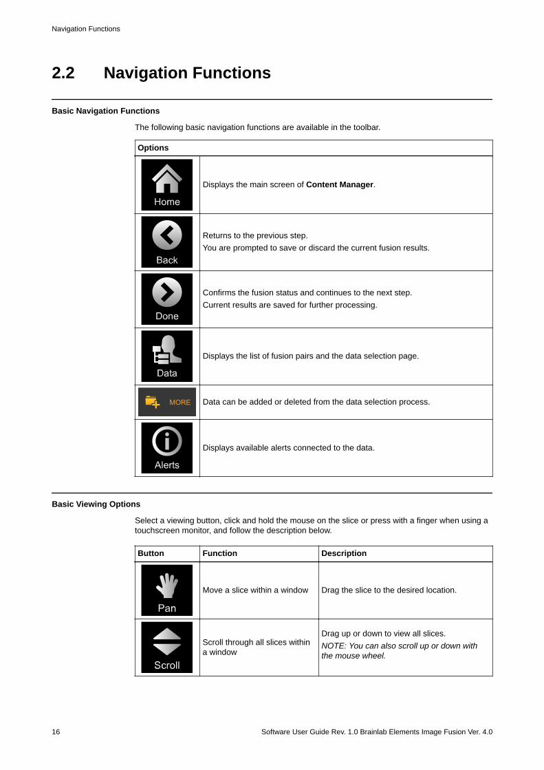
The following basic navigation functions are available in the toolbar.
Options
Displays the main screen of Content Manager.
Returns to the previous step.You are prompted to save or discard the current fusion results.
Confirms the fusion status and continues to the next step.Current results are saved for further processing.
Displays the list of fusion pairs and the data selection page.
Data can be added or deleted from the data selection process.
Displays available alerts connected to the data.
Basic Viewing Options
Select a viewing button, click and hold the mouse on the slice or press with a finger when using atouchscreen monitor, and follow the description below.
Button Function Description
Move a slice within a window Drag the slice to the desired location.
Scroll through all slices withina window
Drag up or down to view all slices.NOTE: You can also scroll up or down withthe mouse wheel.
Navigation Functions
16 Software User Guide Rev. 1.0 Brainlab Elements Image Fusion Ver. 4.0
Button Function Description
Zoom in or out of a slice
• Drag up (zoom out) or down (zoom in).• When using a touchscreen, press two fin-
gers on the image and pinch inward (zoomout) or outward (zoom in).
Adjust the brightness and con-trast of a slice
• Drag down/up to increase/decrease thebrightness.
• Drag right/left to increase/decrease the con-trast level.
Image Adjustment
Button Function
Adjust: Allows you to manually move and rotate the images.
Fusion Options
Button Function
Performs a fusion on the current selection.NOTE: Once a fusion is reviewed and approved, you are promptedto approve the other fusion pairs in your image set.
Allows you to undo recent steps within the application.
Displays the previous/next fusion pair.
SOFTWARE OVERVIEW
Software User Guide Rev. 1.0 Brainlab Elements Image Fusion Ver. 4.0 17

2.3 Reviewing and Verifying Fusion Results
General Information
Verification features available within Image Fusion are:• Spy Glass• Blending• Toggling between both Original and corrected image sets• Windowing
Reviewing and Verifying Fusion Results
18 Software User Guide Rev. 1.0 Brainlab Elements Image Fusion Ver. 4.0
2.3.1 Spy Glass
General Information
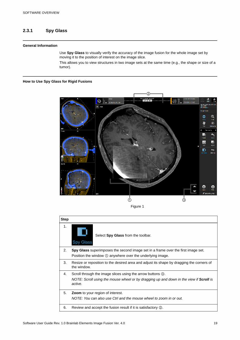
Use Spy Glass to visually verify the accuracy of the image fusion for the whole image set bymoving it to the position of interest on the image slice.This allows you to view structures in two image sets at the same time (e.g., the shape or size of atumor).
How to Use Spy Glass for Rigid Fusions
① ③
②
Figure 1
Step
1.
Select Spy Glass from the toolbar.
2. Spy Glass superimposes the second image set in a frame over the first image set.Position the window ① anywhere over the underlying image.
3. Resize or reposition to the desired area and adjust its shape by dragging the corners ofthe window.
4. Scroll through the image slices using the arrow buttons ③.NOTE: Scroll using the mouse wheel or by dragging up and down in the view if Scroll isactive.
5. Zoom to your region of interest.NOTE: You can also use Ctrl and the mouse wheel to zoom in or out.
6. Review and accept the fusion result if it is satisfactory ②.
SOFTWARE OVERVIEW
Software User Guide Rev. 1.0 Brainlab Elements Image Fusion Ver. 4.0 19

Step
7.
Select Done when complete.The fusion result is saved for further processing.
Spy Glass
20 Software User Guide Rev. 1.0 Brainlab Elements Image Fusion Ver. 4.0
2.3.2 Spy Glass with Elastic Deformation
General Information
Use Spy Glass to visually verify the accuracy of the deformation, by moving it to the area ofinterest on the image slice.This allows you to view structures in two image sets at the same time (e.g., the shape or size of atumor).
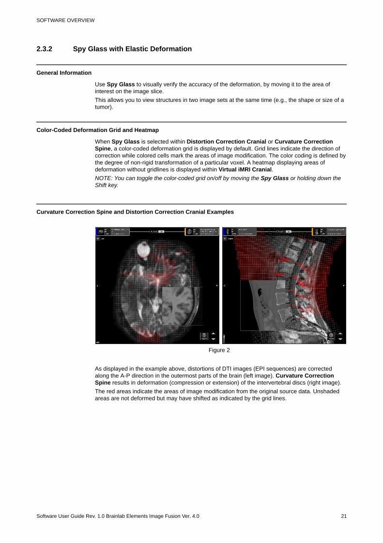
Color-Coded Deformation Grid and Heatmap
When Spy Glass is selected within Distortion Correction Cranial or Curvature CorrectionSpine, a color-coded deformation grid is displayed by default. Grid lines indicate the direction ofcorrection while colored cells mark the areas of image modification. The color coding is defined bythe degree of non-rigid transformation of a particular voxel. A heatmap displaying areas ofdeformation without gridlines is displayed within Virtual iMRI Cranial.NOTE: You can toggle the color-coded grid on/off by moving the Spy Glass or holding down theShift key.
Curvature Correction Spine and Distortion Correction Cranial Examples
Figure 2
As displayed in the example above, distortions of DTI images (EPI sequences) are correctedalong the A-P direction in the outermost parts of the brain (left image). Curvature CorrectionSpine results in deformation (compression or extension) of the intervertebral discs (right image).The red areas indicate the areas of image modification from the original source data. Unshadedareas are not deformed but may have shifted as indicated by the grid lines.
SOFTWARE OVERVIEW
Software User Guide Rev. 1.0 Brainlab Elements Image Fusion Ver. 4.0 21
Virtual iMRI Cranial Example
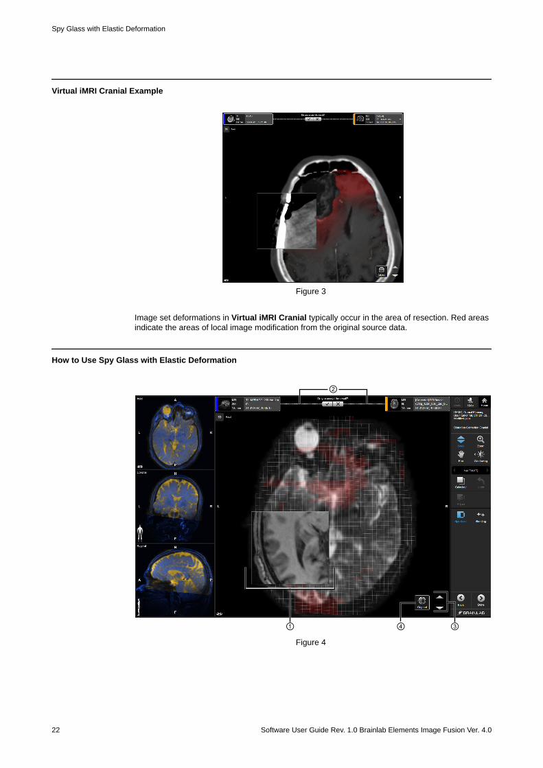
Figure 3
Image set deformations in Virtual iMRI Cranial typically occur in the area of resection. Red areasindicate the areas of local image modification from the original source data.
How to Use Spy Glass with Elastic Deformation
① ③
②
④Figure 4
Spy Glass with Elastic Deformation
22 Software User Guide Rev. 1.0 Brainlab Elements Image Fusion Ver. 4.0
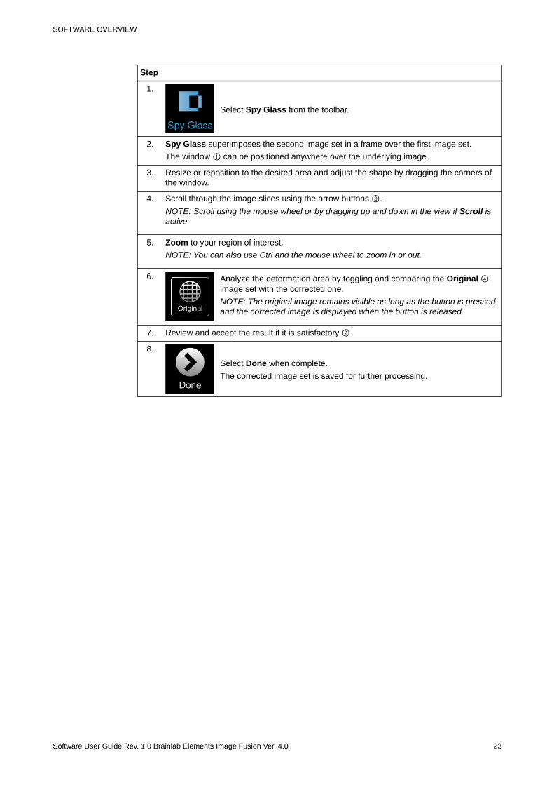
Step
1.
Select Spy Glass from the toolbar.
2. Spy Glass superimposes the second image set in a frame over the first image set.The window ① can be positioned anywhere over the underlying image.
3. Resize or reposition to the desired area and adjust the shape by dragging the corners ofthe window.
4. Scroll through the image slices using the arrow buttons ③.NOTE: Scroll using the mouse wheel or by dragging up and down in the view if Scroll isactive.
5. Zoom to your region of interest.NOTE: You can also use Ctrl and the mouse wheel to zoom in or out.
6. Analyze the deformation area by toggling and comparing the Original ④image set with the corrected one.NOTE: The original image remains visible as long as the button is pressedand the corrected image is displayed when the button is released.
7. Review and accept the result if it is satisfactory ②.
8.
Select Done when complete.The corrected image set is saved for further processing.
SOFTWARE OVERVIEW
Software User Guide Rev. 1.0 Brainlab Elements Image Fusion Ver. 4.0 23
2.3.3 Blending for Rigid Fusions
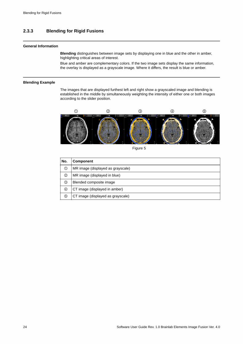
General Information
Blending distinguishes between image sets by displaying one in blue and the other in amber,highlighting critical areas of interest.Blue and amber are complementary colors. If the two image sets display the same information,the overlay is displayed as a grayscale image. Where it differs, the result is blue or amber.
Blending Example
The images that are displayed furthest left and right show a grayscaled image and blending isestablished in the middle by simultaneously weighting the intensity of either one or both imagesaccording to the slider position.
① ② ③ ⑤④
Figure 5
No. Component
① MR image (displayed as grayscale)
② MR image (displayed in blue)
③ Blended composite image
④ CT image (displayed in amber)
⑤ CT image (displayed as grayscale)
Blending for Rigid Fusions
24 Software User Guide Rev. 1.0 Brainlab Elements Image Fusion Ver. 4.0
How to Use Blending
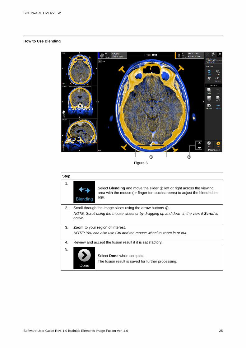
① ②Figure 6
Step
1.Select Blending and move the slider ① left or right across the viewingarea with the mouse (or finger for touchscreens) to adjust the blended im-age.
2. Scroll through the image slices using the arrow buttons ②.NOTE: Scroll using the mouse wheel or by dragging up and down in the view if Scroll isactive.
3. Zoom to your region of interest.NOTE: You can also use Ctrl and the mouse wheel to zoom in or out.
4. Review and accept the fusion result if it is satisfactory.
5.
Select Done when complete.The fusion result is saved for further processing.
SOFTWARE OVERVIEW
Software User Guide Rev. 1.0 Brainlab Elements Image Fusion Ver. 4.0 25
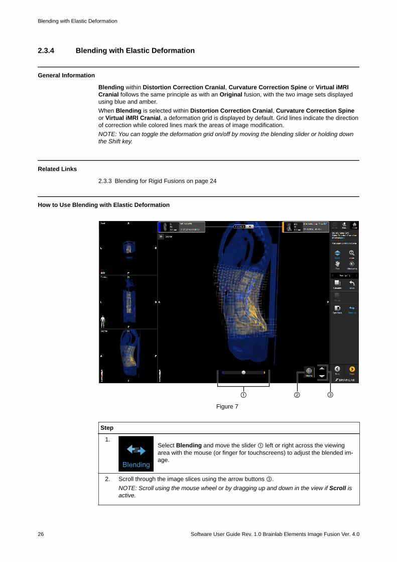
2.3.4 Blending with Elastic Deformation
General Information
Blending within Distortion Correction Cranial, Curvature Correction Spine or Virtual iMRICranial follows the same principle as with an Original fusion, with the two image sets displayedusing blue and amber.When Blending is selected within Distortion Correction Cranial, Curvature Correction Spineor Virtual iMRI Cranial, a deformation grid is displayed by default. Grid lines indicate the directionof correction while colored lines mark the areas of image modification.NOTE: You can toggle the deformation grid on/off by moving the blending slider or holding downthe Shift key.
Related Links
2.3.3 Blending for Rigid Fusions on page 24
How to Use Blending with Elastic Deformation
① ② ③Figure 7
Step
1.Select Blending and move the slider ① left or right across the viewingarea with the mouse (or finger for touchscreens) to adjust the blended im-age.
2. Scroll through the image slices using the arrow buttons ③.NOTE: Scroll using the mouse wheel or by dragging up and down in the view if Scroll isactive.
Blending with Elastic Deformation
26 Software User Guide Rev. 1.0 Brainlab Elements Image Fusion Ver. 4.0

Step
3. Analyze the deformation area by toggling and comparing the Original ②image set with the corrected one.NOTE: The original image remains visible as long as the button is pressedand the corrected image is displayed when the button is released.
4. Review and accept the result if it is satisfactory.
5.
Select Done when complete.The corrected image set is saved for further processing.
SOFTWARE OVERVIEW
Software User Guide Rev. 1.0 Brainlab Elements Image Fusion Ver. 4.0 27
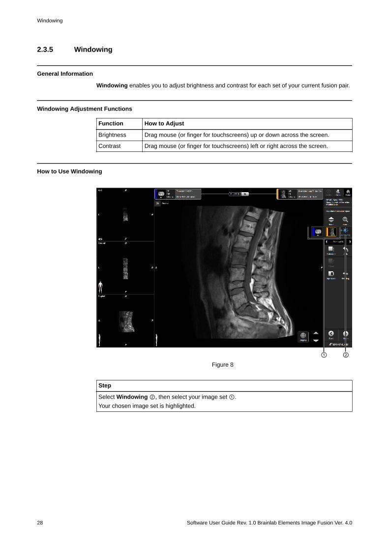
2.3.5 Windowing
General Information
Windowing enables you to adjust brightness and contrast for each set of your current fusion pair.
Windowing Adjustment Functions
Function How to Adjust
Brightness Drag mouse (or finger for touchscreens) up or down across the screen.
Contrast Drag mouse (or finger for touchscreens) left or right across the screen.
How to Use Windowing
① ②Figure 8
Step
Select Windowing ②, then select your image set ①.Your chosen image set is highlighted.
Windowing
28 Software User Guide Rev. 1.0 Brainlab Elements Image Fusion Ver. 4.0
2.4 Manually Adjusting Fusion Results
General Information
If automatic fusion results are unsatisfactory, you can make manual adjustments.Aligning the image set manually sets a starting point to aid the registration algorithm and toimprove fusion results.
How to Adjust for Automatic Fusions
① ② ③
⑤ ④Figure 9
Step
1.
Select Adjust from the toolbar.
2. Move the image by dragging the move control ① until the amber image ⑤ is appropriate-ly positioned.NOTE: You can also use the keyboard arrow keys to position the image set.
3. Rotate the image by selecting and rotating the circle with a dotted line ③ until the amberimage ⑤ is appropriately positioned.NOTE: You can also use Ctrl and the keyboard arrow keys to rotate the image set.
4. Scroll through the image slices using the arrow buttons ④.NOTE: You can also use the mouse wheel to scroll.
5. Use Ctrl and the mouse wheel to zoom in or out.
SOFTWARE OVERVIEW
Software User Guide Rev. 1.0 Brainlab Elements Image Fusion Ver. 4.0 29
Step
6.
• Select Fusion to run an automatic fusion or;• Select Calculate in correction mode to create a corrected image set af-
ter adjusting the current fusion pair.
7. Review and accept the fusion result if it is satisfactory ②.
8.
Select Done when complete.The result is saved for further processing.
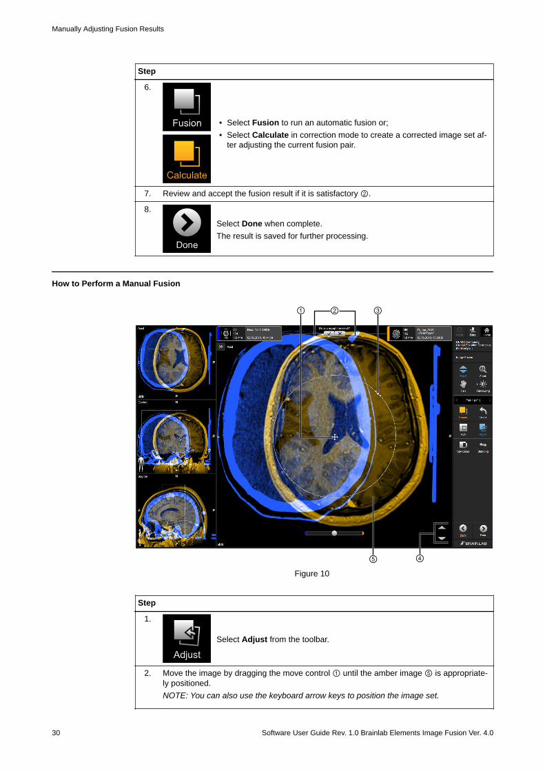
How to Perform a Manual Fusion
① ② ③
⑤ ④Figure 10
Step
1.
Select Adjust from the toolbar.
2. Move the image by dragging the move control ① until the amber image ⑤ is appropriate-ly positioned.NOTE: You can also use the keyboard arrow keys to position the image set.
Manually Adjusting Fusion Results
30 Software User Guide Rev. 1.0 Brainlab Elements Image Fusion Ver. 4.0

Step
3. Rotate the image by selecting and rotating the circle with a dotted line ③ until the amberimage ⑤ is appropriately positioned.NOTE: You can also use Ctrl and the keyboard arrow keys to rotate the image set.
4. Review and accept the fusion result if it is satisfactory ②. The manually adjusted resultcould be saved as a fusion for the current pair.
5.
Select Done when complete.
SOFTWARE OVERVIEW
Software User Guide Rev. 1.0 Brainlab Elements Image Fusion Ver. 4.0 31
2.4.1 Adjusting the ROI (Region of Interest)
General Information
Use the adjustment functions to adjust the fusion area to include all relevant structures fortreatment.Performing image fusion on a manually defined ROI (Region of Interest) restricts the fusionalgorithm to the ROI area. It enables higher fusion accuracy in a limited spatial area.NOTE: The ROI process displays one image set at a time.
NOTE: This feature is only available for rigid image fusion. Manual adjustment of the ROI has noinfluence on the deformation result.
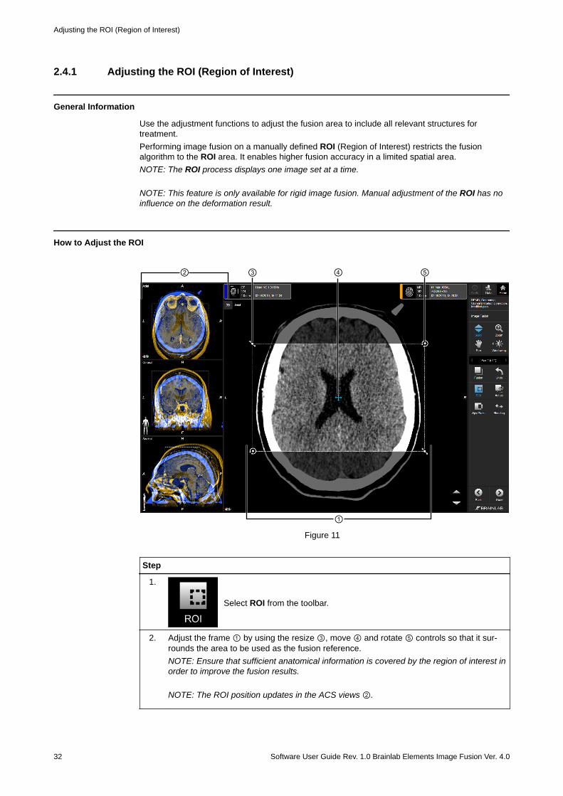
How to Adjust the ROI
② ④ ⑤
①
③
Figure 11
Step
1.
Select ROI from the toolbar.
2. Adjust the frame ① by using the resize ③, move ④ and rotate ⑤ controls so that it sur-rounds the area to be used as the fusion reference.NOTE: Ensure that sufficient anatomical information is covered by the region of interest inorder to improve the fusion results.
NOTE: The ROI position updates in the ACS views ②.
Adjusting the ROI (Region of Interest)
32 Software User Guide Rev. 1.0 Brainlab Elements Image Fusion Ver. 4.0
NOTE: The fusion ROI is only stored for approved fusion pairs when leaving the image fusiontask. Approve and save a result in order to avoid misinterpretation of results and to store for lateruse.
How to Start a Fusion
Step
After finishing a manual adjustment of a ROI, select Fusion.
NOTE: You must select Fusion to apply the fusion algorithm to the newly defined ROI.
How to Break a Fusion
Step
Select X next to FUSED.NOTE: Using X to break the fusion allows you to return to the initial image set alignment. If aROI was defined to perform a fusion, the break action also deletes the manually defined ROI.
SOFTWARE OVERVIEW
Software User Guide Rev. 1.0 Brainlab Elements Image Fusion Ver. 4.0 33
2.5 Using the Fusion Tree and Changing FusionPairs
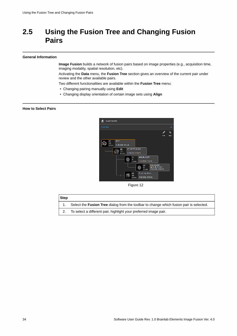
General Information
Image Fusion builds a network of fusion pairs based on image properties (e.g., acquisition time,imaging modality, spatial resolution, etc).Activating the Data menu, the Fusion Tree section gives an overview of the current pair underreview and the other available pairs.Two different functionalities are available within the Fusion Tree menu:• Changing pairing manually using Edit• Changing display orientation of certain image sets using Align
How to Select Pairs
Figure 12
Step
1. Select the Fusion Tree dialog from the toolbar to change which fusion pair is selected.
2. To select a different pair, highlight your preferred image pair.
Using the Fusion Tree and Changing Fusion Pairs
34 Software User Guide Rev. 1.0 Brainlab Elements Image Fusion Ver. 4.0
2.5.1 Fusion Pairing Example
Fusion Pairing Example
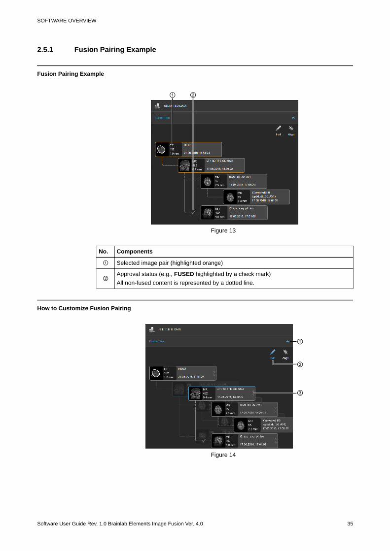
① ②
Figure 13
No. Components
① Selected image pair (highlighted orange)
②Approval status (e.g., FUSED highlighted by a check mark)All non-fused content is represented by a dotted line.
How to Customize Fusion Pairing
①
②
③
Figure 14
SOFTWARE OVERVIEW
Software User Guide Rev. 1.0 Brainlab Elements Image Fusion Ver. 4.0 35
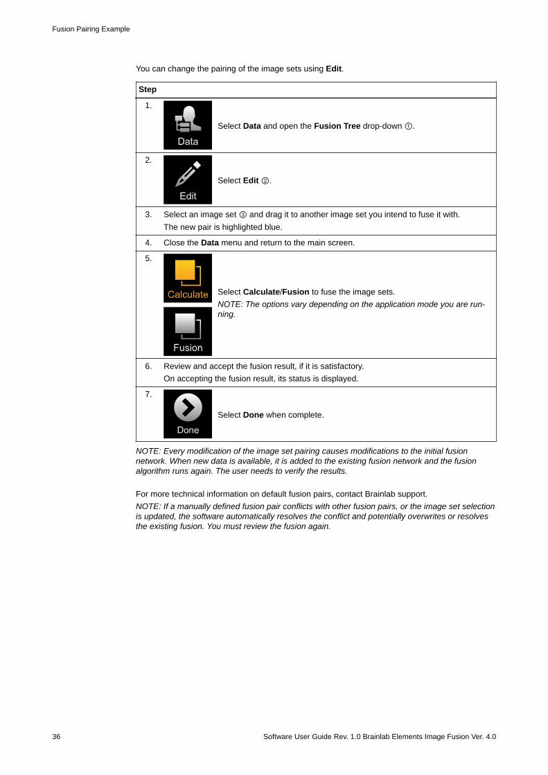
You can change the pairing of the image sets using Edit.
Step
1.
Select Data and open the Fusion Tree drop-down ①.
2.
Select Edit ②.
3. Select an image set ③ and drag it to another image set you intend to fuse it with.The new pair is highlighted blue.
4. Close the Data menu and return to the main screen.
5.
Select Calculate/Fusion to fuse the image sets.NOTE: The options vary depending on the application mode you are run-ning.
6. Review and accept the fusion result, if it is satisfactory.On accepting the fusion result, its status is displayed.
7.
Select Done when complete.
NOTE: Every modification of the image set pairing causes modifications to the initial fusionnetwork. When new data is available, it is added to the existing fusion network and the fusionalgorithm runs again. The user needs to verify the results.
For more technical information on default fusion pairs, contact Brainlab support.NOTE: If a manually defined fusion pair conflicts with other fusion pairs, or the image set selectionis updated, the software automatically resolves the conflict and potentially overwrites or resolvesthe existing fusion. You must review the fusion again.
Fusion Pairing Example
36 Software User Guide Rev. 1.0 Brainlab Elements Image Fusion Ver. 4.0
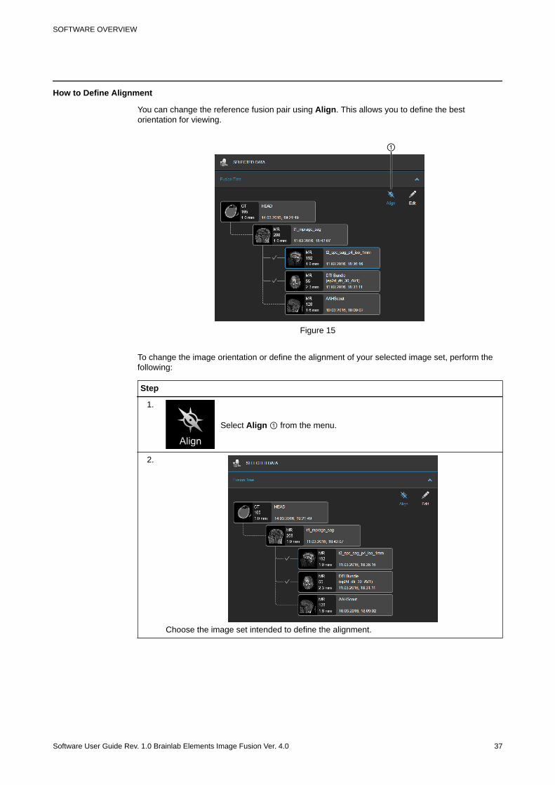
How to Define Alignment
You can change the reference fusion pair using Align. This allows you to define the bestorientation for viewing.
①
Figure 15
To change the image orientation or define the alignment of your selected image set, perform thefollowing:
Step
1.
Select Align ① from the menu.
2.
Choose the image set intended to define the alignment.
SOFTWARE OVERVIEW
Software User Guide Rev. 1.0 Brainlab Elements Image Fusion Ver. 4.0 37
2.6 Finalizing and Closing Image Fusion
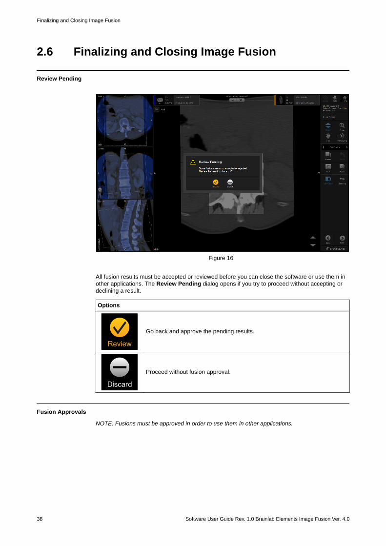
Review Pending
Figure 16
All fusion results must be accepted or reviewed before you can close the software or use them inother applications. The Review Pending dialog opens if you try to proceed without accepting ordeclining a result.
Options
Go back and approve the pending results.
Proceed without fusion approval.
Fusion Approvals
NOTE: Fusions must be approved in order to use them in other applications.
Finalizing and Closing Image Fusion
38 Software User Guide Rev. 1.0 Brainlab Elements Image Fusion Ver. 4.0
Deformation Results
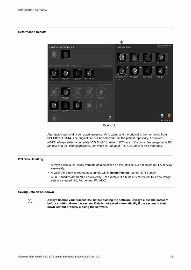
①
Figure 17
After fusion approval, a corrected image set ① is saved and the original is then removed fromSELECTED DATA. The original can still be selected from the patient repository, if required.NOTE: Always select a complete "DTI Study" to deform DTI data. If the corrected image set is B0(as part of a DTI data acquisition), the whole DTI dataset (FA, ADC map) is also deformed.
DTI Data Handling
• Always select a DTI study from the data selection on the left side. Do not select B0, FA or ADCseparately.
• A valid DTI study is treated as a bundle within Image Fusion, named "DTI Bundle".• All DTI bundles are treated equivalently. For example, if a bundle is corrected, four new image
sets are created (B0, FA, colored FA, ADC).
Saving Data on Shutdown
Always finalize your current task before closing the software. Always close the softwarebefore shutting down the system. Data is not saved automatically if the system is shutdown without properly closing the software.
SOFTWARE OVERVIEW
Software User Guide Rev. 1.0 Brainlab Elements Image Fusion Ver. 4.0 39
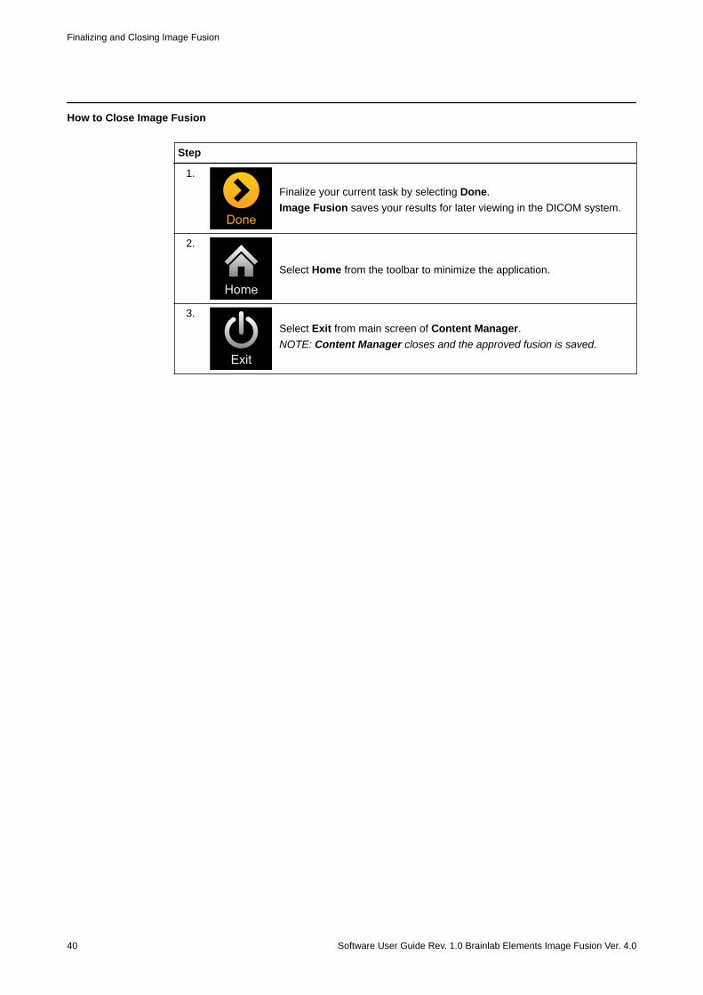
How to Close Image Fusion
Step
1.
Finalize your current task by selecting Done.Image Fusion saves your results for later viewing in the DICOM system.
2.
Select Home from the toolbar to minimize the application.
3.Select Exit from main screen of Content Manager.NOTE: Content Manager closes and the approved fusion is saved.
Finalizing and Closing Image Fusion
40 Software User Guide Rev. 1.0 Brainlab Elements Image Fusion Ver. 4.0
3 CRANIAL PROCEDURES3.1 Image Fusion for Cranial Procedures
General Information
When starting a cranial workflow, you can choose between:• Image Fusion• Distortion Correction Cranial• Virtual iMRI Cranial
The images are fused based on common anatomical structures visible in both image sets.The aim is to review the quality of the fusion results, and, if satisfactory, approve the fusion. Thefusion is saved by selecting Done.
WarningAlways verify the results on the whole image set before approving and saving them.NOTE: The fusion is based on common anatomical structures and is affected by brightnessvariations within the image slices.
Cranial Screen Layout
①
④
③②
Figure 18
CRANIAL PROCEDURES
Software User Guide Rev. 1.0 Brainlab Elements Image Fusion Ver. 4.0 41

No. Explanation
① Axial, coronal and sagittal reconstructions as a preview of the current result.
② Axial, coronal and sagittal view selector.
③ Region of interest (ROI) used for rigid fusion is displayed as a dotted line in the main viewand the ACS reconstructions ①.
④ The current fused pair is displayed as an overlay, which can also be previewed within theACS reconstructions ①.
Related Links
2.3.2 How to Adjust the ROI on page 32
Image Fusion for Cranial Procedures
42 Software User Guide Rev. 1.0 Brainlab Elements Image Fusion Ver. 4.0
3.1.2 Starting Image Fusion
Before You Begin
Use Patient Selection to select the patient and desired data. Refer to the Patient Data ManagerSoftware User Guide for more information.NOTE: Adding or removing data influences how the algorithm creates the fusion network.
Image Modification
NOTE: Modifying image sets outside Image Fusion when already in use can lead to corruptionsor inaccuracies.
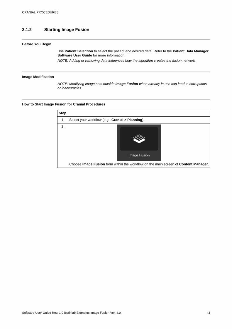
How to Start Image Fusion for Cranial Procedures
Step
1. Select your workflow (e.g., Cranial > Planning).
2.
Choose Image Fusion from within the workflow on the main screen of Content Manager.
CRANIAL PROCEDURES
Software User Guide Rev. 1.0 Brainlab Elements Image Fusion Ver. 4.0 43
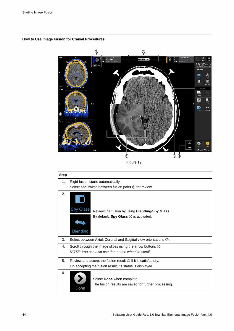
How to Use Image Fusion for Cranial Procedures
① ⑤
③
④
②
Figure 19
Step
1. Rigid fusion starts automatically.Select and switch between fusion pairs ⑤ for review.
2.
Review the fusion by using Blending/Spy Glass.By default, Spy Glass ① is activated.
3. Select between Axial, Coronal and Sagittal view orientations ②.
4. Scroll through the image slices using the arrow buttons ④.NOTE: You can also use the mouse wheel to scroll.
5. Review and accept the fusion result ③ if it is satisfactory.On accepting the fusion result, its status is displayed.
6.
Select Done when complete.The fusion results are saved for further processing.
Starting Image Fusion
44 Software User Guide Rev. 1.0 Brainlab Elements Image Fusion Ver. 4.0

Related Links
2.3 Reviewing and Verifying Fusion Results on page 18
CRANIAL PROCEDURES
Software User Guide Rev. 1.0 Brainlab Elements Image Fusion Ver. 4.0 45
3.2 Distortion Correction Cranial
General Information
Certain imaging modalities are susceptible to geometric distortions arising from (e.g., systemimperfections and gradient nonlinearities of the imaging system). Consequently, inaccuracieswithin rigid fusion results may exist after automatic fusion, manual adjustment or applying ROIfusion.You can choose Distortion Correction Cranial to obtain a better match between images.Distortion Correction Cranial creates a corrected image set by deforming it to better match thedefined reference image set. The aim is then to review the corrected image set and potentialcontents that were present in the image set, and if satisfactory, approve the result.
WarningAlways verify fusion results on the whole image set before approving and saving them.NOTE: The fusion is based on common anatomical structures and is affected by brightnessvariations in the image slices and scan quality.
NOTE: Image sets corrected by Distortion Correction Cranial are not recommended for patientregistration.
Recommendations
Image data for Distortion Correction Cranial should follow these recommendations to ensurethe best results:• Image pairs should cover an intersecting volume of the patient.• A minimum of 10 slices• A slice distance lower than 4 mm (slice thickness lower than 4 mm and an acquisition without
gaps are recommended)• Full DICOM information (i.e., complete DICOM header, indicating e.g., acquisition parameters)• Good raw image quality (e.g., high resolution, high contrast, minimal artifacts)
Supported Image Modalities
The following imaging modalities are supported for Distortion Correction Cranial, if paired asfollows:• CT-MR• MR-MR• MR-DTI
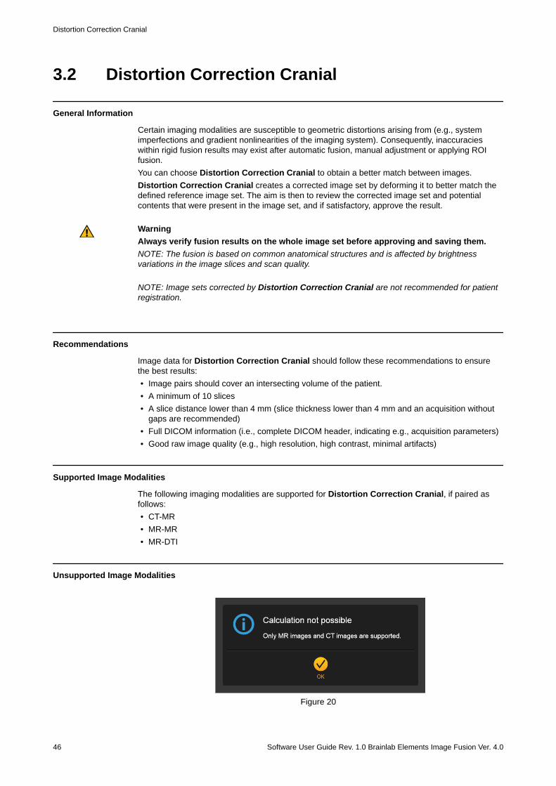
Unsupported Image Modalities
Figure 20
Distortion Correction Cranial
46 Software User Guide Rev. 1.0 Brainlab Elements Image Fusion Ver. 4.0
The following special modalities and sequence types are not supported for direct calculation:• Previously deformed image sets• RGB images• FA and ADC maps• Phase and velocity maps• Perfusion maps• Spectroscopy images• Gradient calibration scans• FLAWS scans (fluid and white matter suppression)• Subtraction images and projections (Minimum/Maximum Intensity Projections)• Image sets containing burned-in objects
Supported Content
The following content is supported and corrected based on the deformation of an image set:• Voxel objects• Labeled points• Trajectories• Fiber bundles (e.g., DTI fiber tracts)
How to Start Distortion Correction Cranial
Step
Choose Distortion Correction Cranial from the main screen of Content Manager.
CRANIAL PROCEDURES
Software User Guide Rev. 1.0 Brainlab Elements Image Fusion Ver. 4.0 47
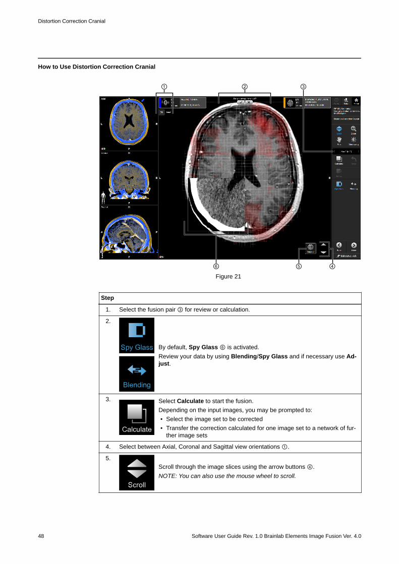
How to Use Distortion Correction Cranial
③
⑤
①
④
②
⑥Figure 21
Step
1. Select the fusion pair ③ for review or calculation.
2.
By default, Spy Glass ⑥ is activated.Review your data by using Blending/Spy Glass and if necessary use Ad-just.
3. Select Calculate to start the fusion.Depending on the input images, you may be prompted to:• Select the image set to be corrected• Transfer the correction calculated for one image set to a network of fur-
ther image sets
4. Select between Axial, Coronal and Sagittal view orientations ①.
5.Scroll through the image slices using the arrow buttons ④.NOTE: You can also use the mouse wheel to scroll.
Distortion Correction Cranial
48 Software User Guide Rev. 1.0 Brainlab Elements Image Fusion Ver. 4.0
Step
6.Review and verify the distortion correction by toggling between Blend-ing/Spy Glass.Toggle Original ⑤ to compare the simulation with the original image.
7. Review and accept the fusion result ② if it is satisfactory.
8.
Select Done when complete.The corrected image set is saved for further processing.
WarningConsider the impact of making modifications within Distortion Correction Cranial to pre-existing objects and other planning contents (e.g., points, trajectories or fiber bundles).Always verify the shape and position of planning content within DICOM Viewer/Viewer orthe Element used to create the content.NOTE: Distortion Correction Cranial results are saved as a new DICOM image set, containing theprefix [Corrected]. The original image sets are replaced by the corrected data and stored locally.
CRANIAL PROCEDURES
Software User Guide Rev. 1.0 Brainlab Elements Image Fusion Ver. 4.0 49
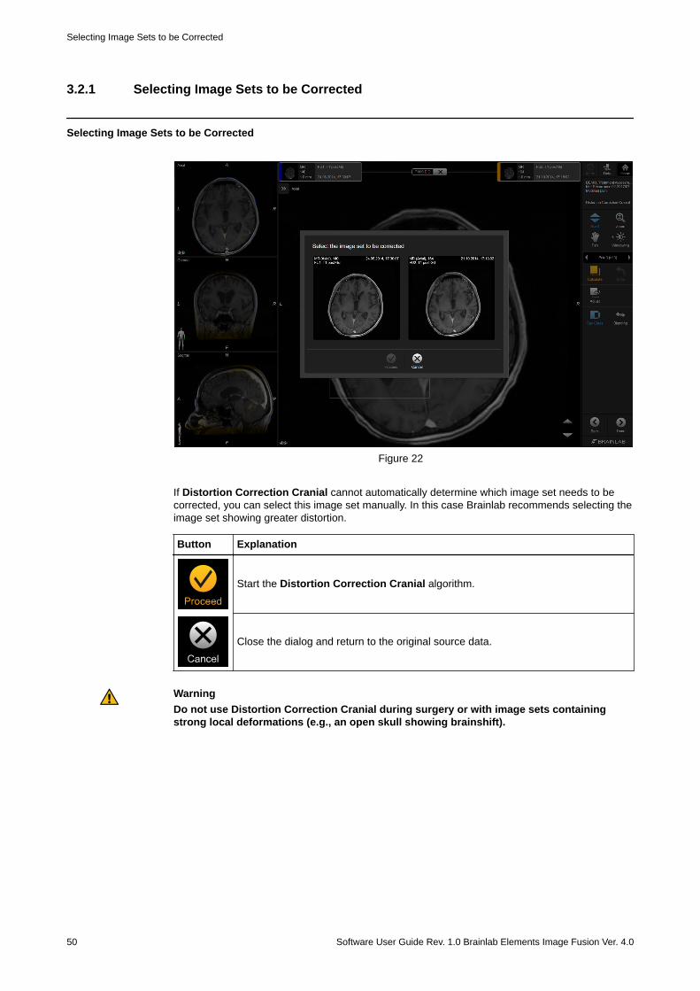
3.2.1 Selecting Image Sets to be Corrected
Selecting Image Sets to be Corrected
Figure 22
If Distortion Correction Cranial cannot automatically determine which image set needs to becorrected, you can select this image set manually. In this case Brainlab recommends selecting theimage set showing greater distortion.
Button Explanation
Start the Distortion Correction Cranial algorithm.
Close the dialog and return to the original source data.
WarningDo not use Distortion Correction Cranial during surgery or with image sets containingstrong local deformations (e.g., an open skull showing brainshift).
Selecting Image Sets to be Corrected
50 Software User Guide Rev. 1.0 Brainlab Elements Image Fusion Ver. 4.0
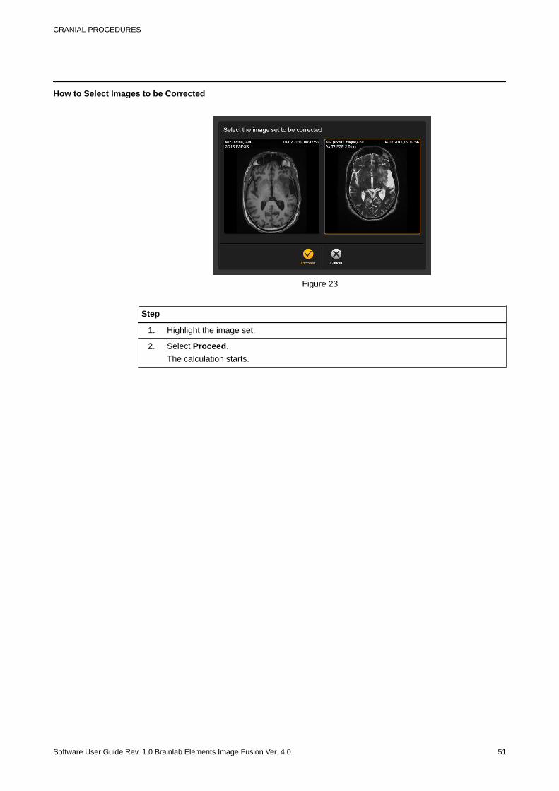
How to Select Images to be Corrected
Figure 23
Step
1. Highlight the image set.
2. Select Proceed.The calculation starts.
CRANIAL PROCEDURES
Software User Guide Rev. 1.0 Brainlab Elements Image Fusion Ver. 4.0 51
3.2.2 Cluster Deformation with Distortion Correction Cranial
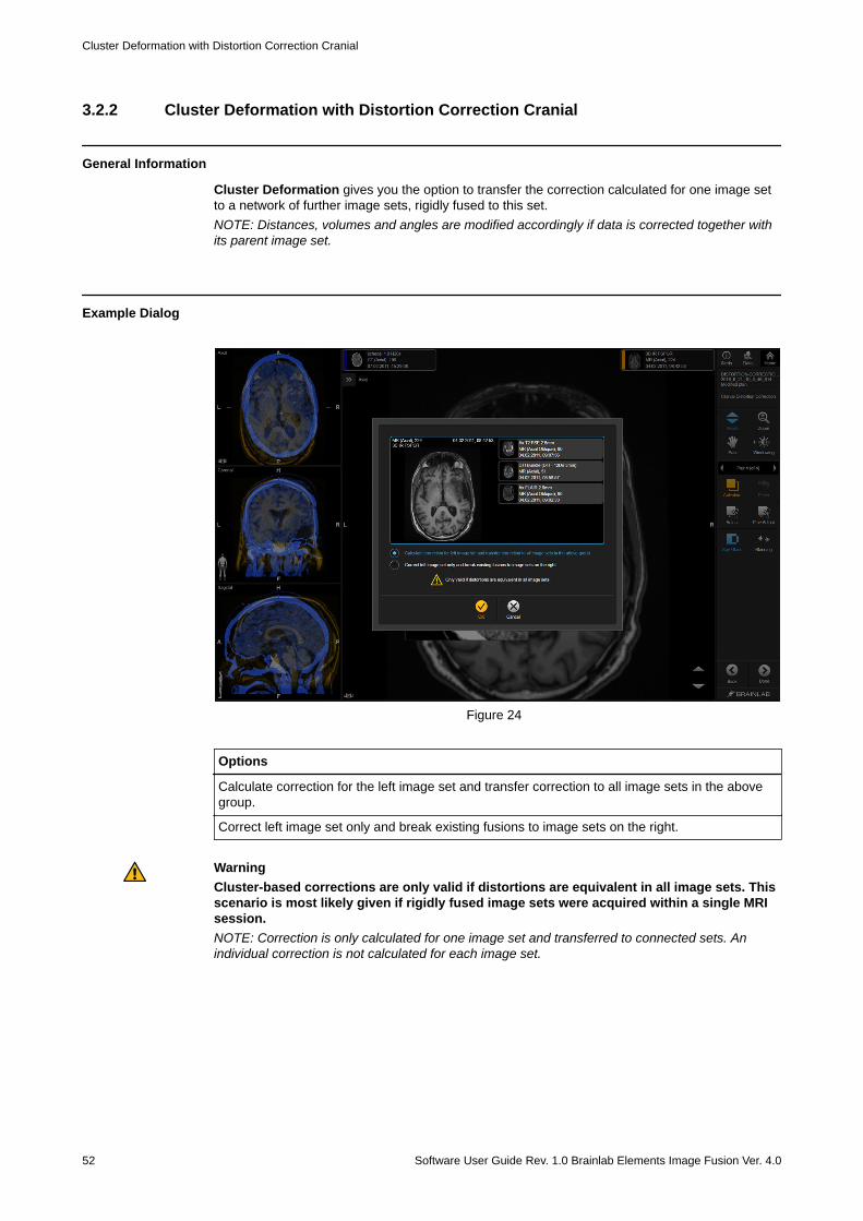
General Information
Cluster Deformation gives you the option to transfer the correction calculated for one image setto a network of further image sets, rigidly fused to this set.NOTE: Distances, volumes and angles are modified accordingly if data is corrected together withits parent image set.
Example Dialog
Figure 24
Options
Calculate correction for the left image set and transfer correction to all image sets in the abovegroup.
Correct left image set only and break existing fusions to image sets on the right.
WarningCluster-based corrections are only valid if distortions are equivalent in all image sets. Thisscenario is most likely given if rigidly fused image sets were acquired within a single MRIsession.NOTE: Correction is only calculated for one image set and transferred to connected sets. Anindividual correction is not calculated for each image set.
Cluster Deformation with Distortion Correction Cranial
52 Software User Guide Rev. 1.0 Brainlab Elements Image Fusion Ver. 4.0
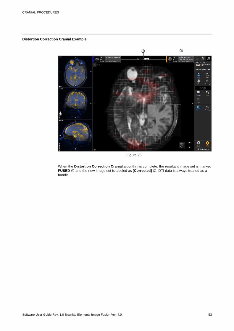
Distortion Correction Cranial Example
① ②
Figure 25
When the Distortion Correction Cranial algorithm is complete, the resultant image set is markedFUSED ① and the new image set is labeled as [Corrected] ②. DTI data is always treated as abundle.
CRANIAL PROCEDURES
Software User Guide Rev. 1.0 Brainlab Elements Image Fusion Ver. 4.0 53
3.3 Contrast Clearance Analysis
General Information
Contrast Clearance Analysis* visualizes the accumulation of a contrast agent against its rate ofclearance. The method works by acquiring two MRI series – one at five minutes and another atapprox. 75 minutes after injection of a standard dose of contrast agent – and subtracting the firstseries from the second, resulting in a high-resolution color-coded map. Use Image Fusion to fuseand compare the two MRI image sets.* Developed at Sheba Medical Center with technology provided by Brainlab.
Example
Figure 26
Color Explanation
Red Accumulation of the contrast agent (slow clearance)
Blue Clearance of the contrast agent (fast clearance)
Requirements
The Contrast Clearance Analysis calculation requires two 3D MRI data sets. For these:• Both sequences must be acquired using the equivalent scan protocol• The first sequence must be taken approx. five minutes after contrast agent injection (using e.g.,
Gd/Gadolinium)• The second sequence must be taken 60-105 minutes after contrast agent injection
Contrast Clearance Analysis
54 Software User Guide Rev. 1.0 Brainlab Elements Image Fusion Ver. 4.0
How to Start Contrast Clearance Analysis
Step
Choose Contrast Clearance Analysis from the main screen of Content Manager.
How to Use Contrast Clearance Analysis
②
①
③Figure 27
Step
1. Select the first and second MRI data sets (i.e., early and late image acquisitions after thecontrast agent injection).
2.Select Calculate to start the Contrast Clearance Analysis calculation.A rigid fusion of both MR sequences is performed automatically prior to thecalculation.
3. Select between Axial, Coronal and Sagittal view orientations ①.
4. Scroll through the image slices using the arrow buttons ②.NOTE: You can also use the mouse wheel to scroll.
CRANIAL PROCEDURES
Software User Guide Rev. 1.0 Brainlab Elements Image Fusion Ver. 4.0 55
Step
5. Review the accumulation/clearance of the contrast agent.
6.
By default, Spy Glass ③ is activated.Review the fusion by using Blending/Spy Glass.
7. Review and accept the fusion result ② if it is satisfactory.
8.
Select Done when complete.The fusion results are saved for further processing.
NOTE: Resulting image sets are saved as a new DICOM RGB image set, fused to the first MRimage set (taken shortly after contrast agent injection). The second (later) MR image set isremoved from your current data selection automatically after calculation.
Related Links
3.3 Contrast Clearance Analysis on page 542.3 Reviewing and Verifying Fusion Results on page 18
Contrast Clearance Analysis
56 Software User Guide Rev. 1.0 Brainlab Elements Image Fusion Ver. 4.0
3.4 Virtual iMRI Cranial
General Information
Patient anatomy changes during surgery. Using intraoperative imaging techniques, it is possible toobtain new image sets depicting the actual modified patient anatomy.By means of Virtual iMRI Cranial you may achieve an improved spatial matching of pre- andintraoperative image data by elastically morphing preoperative planning information onto anintraoperative scan and accounting for surgery-related brainshift due to CSF leakage.Virtual iMRI Cranial creates a virtual image set by simulating tissue modifications of apreoperative image set and applying a deformation field, in order to better match theintraoperative reference image set. The aim is then to review the virtual image set together withany other potential content and/or other image sets present in the preoperative plan with respectto the intraoperative image set, and if satisfactory, approve the result.
WarningAlways verify fusion results on the whole image set before approving and saving them.NOTE: Image sets corrected by Virtual iMRI Cranial are not recommended for patientregistration.
NOTE: Virtual iMRI Cranial delivers a simulation of the potential intraoperative situation asimaged by an intraoperatively acquired image set, only. A user-defined resection cavity serves asinput for the simulation.It is not intended to show residual tumors or the absence of residual tumors.
Recommendations
Image data for Virtual iMRI Cranial should follow these recommendations to ensure the bestresults:• Image pairs should cover an intersecting volume of the patient.• A minimum of 10 slices• A slice distance lower than 3 mm (slice thickness lower than 3 mm and an acquisition without
gaps are recommended)• Full DICOM information (i.e., complete DICOM header, indicating e.g., acquisition parameters)• If MRI data needs correcting, it should be acquired as a 3D or 2D-axial sequence with a T1-
weighting (a T2-weighting or fat suppressed acquisition is also recommended).• Intraoperative image acquisition should be performed with the bone flap back in place (i.e., the
skull is closed/covered by the bone flap again)• Good raw image quality (e.g., high resolution, high contrast, minimal artifacts)
Supported Image Modalities
The following imaging modalities are supported for Virtual iMRI Cranial, if paired as follows:• CT-MR• MR-MR
CRANIAL PROCEDURES
Software User Guide Rev. 1.0 Brainlab Elements Image Fusion Ver. 4.0 57
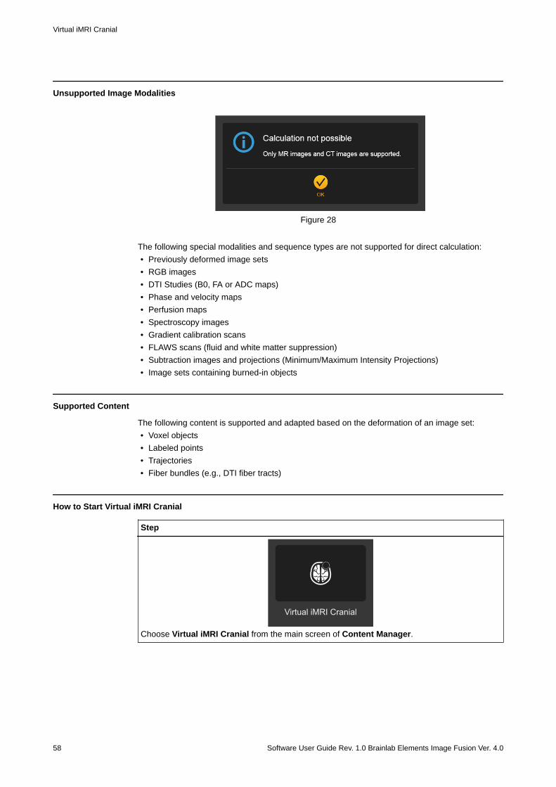
Unsupported Image Modalities
Figure 28
The following special modalities and sequence types are not supported for direct calculation:• Previously deformed image sets• RGB images• DTI Studies (B0, FA or ADC maps)• Phase and velocity maps• Perfusion maps• Spectroscopy images• Gradient calibration scans• FLAWS scans (fluid and white matter suppression)• Subtraction images and projections (Minimum/Maximum Intensity Projections)• Image sets containing burned-in objects
Supported Content
The following content is supported and adapted based on the deformation of an image set:• Voxel objects• Labeled points• Trajectories• Fiber bundles (e.g., DTI fiber tracts)
How to Start Virtual iMRI Cranial
Step
Choose Virtual iMRI Cranial from the main screen of Content Manager.
Virtual iMRI Cranial
58 Software User Guide Rev. 1.0 Brainlab Elements Image Fusion Ver. 4.0
How to Use Virtual iMRI Cranial
③
①
④
②
Figure 29
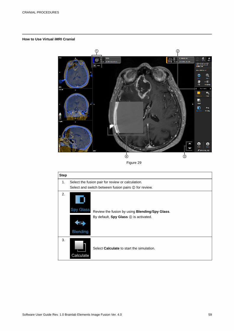
Step
1. Select the fusion pair for review or calculation.Select and switch between fusion pairs ② for review.
2.
Review the fusion by using Blending/Spy Glass.By default, Spy Glass ④ is activated.
3.
Select Calculate to start the simulation.
CRANIAL PROCEDURES
Software User Guide Rev. 1.0 Brainlab Elements Image Fusion Ver. 4.0 59
Step
4.
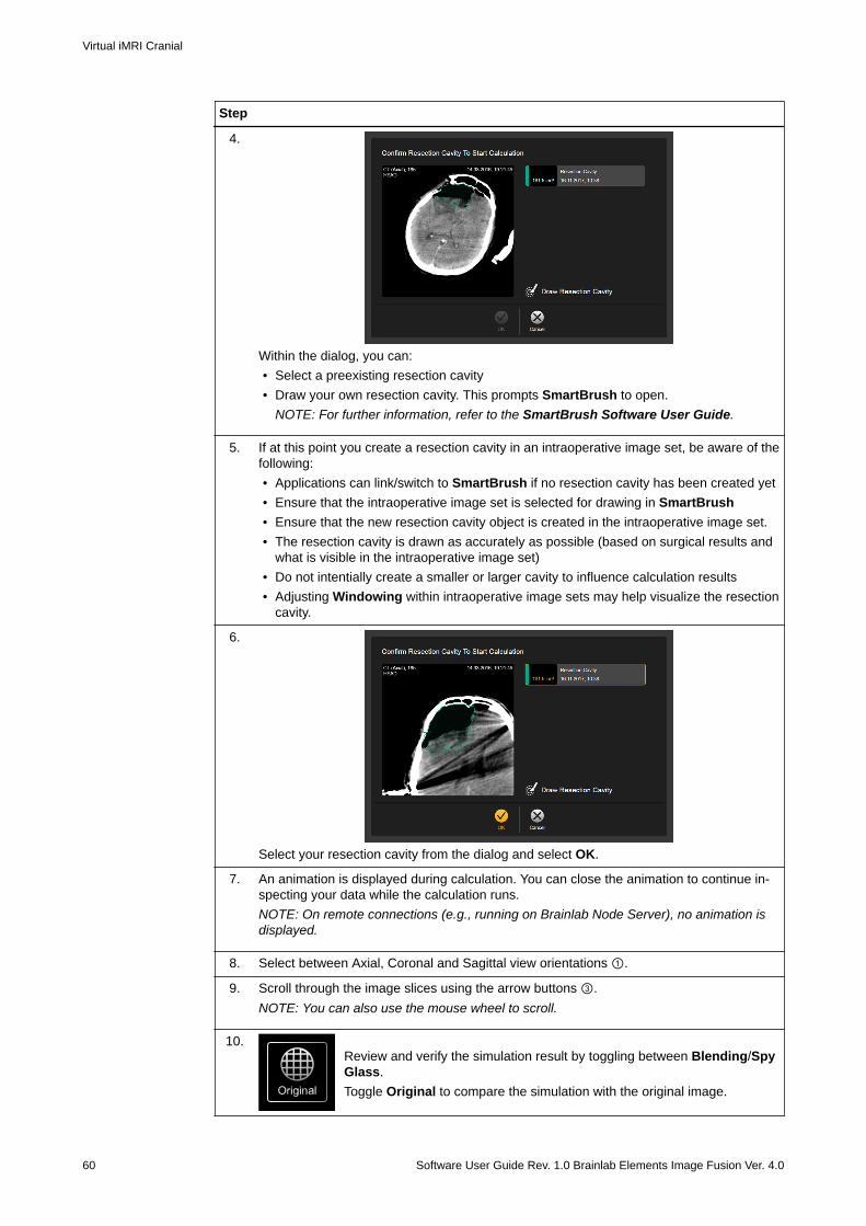
Within the dialog, you can:• Select a preexisting resection cavity• Draw your own resection cavity. This prompts SmartBrush to open.
NOTE: For further information, refer to the SmartBrush Software User Guide.
5. If at this point you create a resection cavity in an intraoperative image set, be aware of thefollowing:• Applications can link/switch to SmartBrush if no resection cavity has been created yet• Ensure that the intraoperative image set is selected for drawing in SmartBrush• Ensure that the new resection cavity object is created in the intraoperative image set.• The resection cavity is drawn as accurately as possible (based on surgical results and
what is visible in the intraoperative image set)• Do not intentially create a smaller or larger cavity to influence calculation results• Adjusting Windowing within intraoperative image sets may help visualize the resection
cavity.
6.
Select your resection cavity from the dialog and select OK.
7. An animation is displayed during calculation. You can close the animation to continue in-specting your data while the calculation runs.NOTE: On remote connections (e.g., running on Brainlab Node Server), no animation isdisplayed.
8. Select between Axial, Coronal and Sagittal view orientations ①.
9. Scroll through the image slices using the arrow buttons ③.NOTE: You can also use the mouse wheel to scroll.
10.Review and verify the simulation result by toggling between Blending/SpyGlass.Toggle Original to compare the simulation with the original image.
Virtual iMRI Cranial
60 Software User Guide Rev. 1.0 Brainlab Elements Image Fusion Ver. 4.0
Step
11. Review and accept the fusion result, if it is satisfactory.On accepting the fusion result, its status is displayed.
12.
Select Done when complete.The fusion results are saved for further processing.
NOTE: Virtual iMRI Cranial results are saved as a new DICOM image set, containing the prefix[Virtual]. The original image sets are replaced by the corrected data and stored locally.
WarningConsider the impact of making modifications within Virtual iMRI Cranial to pre-existingobjects and other planning contents (e.g., points, trajectories or fiber bundles). Alwaysverify the shape and position of planning content within DICOM Viewer/Viewer or theElement used to create the content.
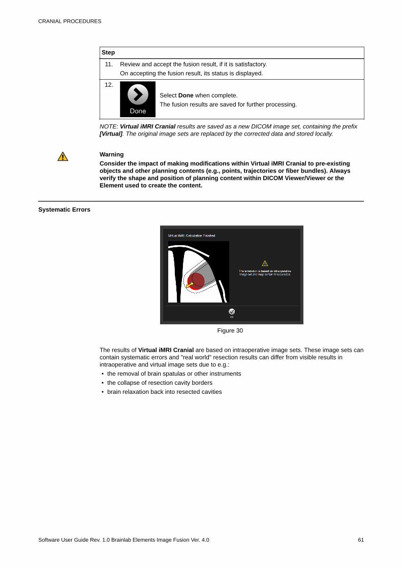
Systematic Errors
Figure 30
The results of Virtual iMRI Cranial are based on intraoperative image sets. These image sets cancontain systematic errors and "real world" resection results can differ from visible results inintraoperative and virtual image sets due to e.g.:• the removal of brain spatulas or other instruments• the collapse of resection cavity borders• brain relaxation back into resected cavities
CRANIAL PROCEDURES
Software User Guide Rev. 1.0 Brainlab Elements Image Fusion Ver. 4.0 61
3.4.1 Cluster Deformation with Virtual iMRI Cranial
General Information
All preoperative image sets which are fused to the target image set are also deformed bytransferring the deformation field.NOTE: Potential risks could occur if preoperative data shows different patient situations (e.g.,when the current image set is fused to an image set from the past or the size of tumor or edemahas changed in between image sets).
WarningCluster-based correction is only valid if preoperative data used in calculation (e.g.,simulation, implicit deformation etc.) depicts the equivalent patient situation. Anyindividual deviations in between preoperative image sets are not corrected.NOTE: Distances, volumes and angles are modified accordingly if data is corrected together withits parent image set.
Cluster Deformation with Virtual iMRI Cranial
62 Software User Guide Rev. 1.0 Brainlab Elements Image Fusion Ver. 4.0
3.4.2 Virtual iMRI Cranial Results
Virtual iMRI Cranial Example using iCT
① ② ③
Figure 31
When the Virtual iMRI Cranial algorithm is complete, the resultant image set is marked FUSED① and the new image set is labeled as [Virtual] ②. Image sets of preoperative plans which havebeen deformed implicitely can be accessed and overlayed ③.In intraoperative CT imaging, the virtual image set is composed of updated and deformed softtissue anatomy from preoperative imaging and the bony anatomy from intraoperative imaging.NOTE: The bone flap should be repositioned by a surgeon prior to the acquisition of intraoperativescans (especially for iCT).
CRANIAL PROCEDURES
Software User Guide Rev. 1.0 Brainlab Elements Image Fusion Ver. 4.0 63
Virtual iMRI Cranial Example using iMRI
① ② ③
Figure 32
When the Virtual iMRI Cranial algorithm is complete, the resultant image set is marked FUSED① and the new image set is labeled as [Virtual] ②. Image sets of preoperative plans which havebeen deformed implicitely can be accessed and overlayed ③.In MR imaging, the virtual image set is composed of updated and deformed soft tissue anatomyfrom preoperative imaging only.
Virtual iMRI Cranial Results
64 Software User Guide Rev. 1.0 Brainlab Elements Image Fusion Ver. 4.0
4 SPINE PROCEDURES4.1 Image Fusion for Spinal Procedures
General Information
When starting a spine workflow, you can choose between:• Image Fusion• Curvature Correction Spine
The images are fused together based on anatomical structures common to both image sets.The aim is to review the quality of the fusion results, and, if satisfactory, approve the fusion. Thefusion is saved by selecting Done.
WarningAlways verify fusion results on the whole image set before approving and saving them.NOTE: Fusion is not triggered automatically within a spine workflow. You must start a fusionmanually.
NOTE: The fusion is based on common anatomical structures and is affected by brightnessvariations within the image slices.
Spine Screen Layout
④
③②
①
Figure 33
SPINE PROCEDURES
Software User Guide Rev. 1.0 Brainlab Elements Image Fusion Ver. 4.0 65
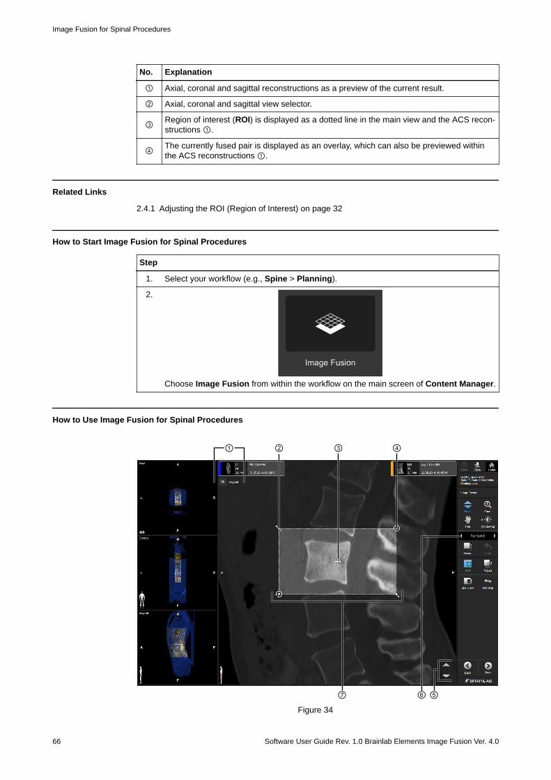
No. Explanation
① Axial, coronal and sagittal reconstructions as a preview of the current result.
② Axial, coronal and sagittal view selector.
③ Region of interest (ROI) is displayed as a dotted line in the main view and the ACS recon-structions ①.
④ The currently fused pair is displayed as an overlay, which can also be previewed withinthe ACS reconstructions ①.
Related Links
2.4.1 Adjusting the ROI (Region of Interest) on page 32
How to Start Image Fusion for Spinal Procedures
Step
1. Select your workflow (e.g., Spine > Planning).
2.
Choose Image Fusion from within the workflow on the main screen of Content Manager.
How to Use Image Fusion for Spinal Procedures
③②①
⑥⑦ ⑤
④
Figure 34
Image Fusion for Spinal Procedures
66 Software User Guide Rev. 1.0 Brainlab Elements Image Fusion Ver. 4.0
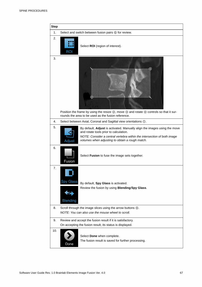
Step
1. Select and switch between fusion pairs ⑥ for review.
2.
Select ROI (region of interest).
3.
Position the frame by using the resize ②, move ③ and rotate ④ controls so that it sur-rounds the area to be used as the fusion reference.
4. Select between Axial, Coronal and Sagittal view orientations ①.
5. By default, Adjust is activated. Manually align the images using the moveand rotate tools prior to calculation.NOTE: Consider a central vertebra within the intersection of both imagevolumes when adjusting to obtain a rough match.
6.
Select Fusion to fuse the image sets together.
7.
By default, Spy Glass is activated.Review the fusion by using Blending/Spy Glass.
8. Scroll through the image slices using the arrow buttons ⑤.NOTE: You can also use the mouse wheel to scroll.
9. Review and accept the fusion result if it is satisfactory.On accepting the fusion result, its status is displayed.
10.
Select Done when complete.The fusion result is saved for further processing.
SPINE PROCEDURES
Software User Guide Rev. 1.0 Brainlab Elements Image Fusion Ver. 4.0 67

Related Links
2.3 Reviewing and Verifying Fusion Results on page 18
Image Fusion for Spinal Procedures
68 Software User Guide Rev. 1.0 Brainlab Elements Image Fusion Ver. 4.0
4.2 Curvature Correction Spine
General Information
The position of a patient might change between different image acquisitions. Consequently,inaccuracies within rigid fusion results may exist after automatic fusion, manual adjustment orapplying a ROI fusion. You can choose Curvature Correction Spine to obtain a better matchbetween images.Curvature Correction Spine creates a deformed image set that better matches the originalimage set.The aim is then to review the corrected image set and potential contents that were present in theimage set, and if satisfactory, approve the result.
WarningAlways verify fusion results on the whole image set before approving and saving them.NOTE: The fusion is based on common anatomical structures and is affected by brightnessvariations in the image slices and scan quality.
NOTE: Image sets corrected by Curvature Correction Spine are not recommended for patientregistration.
Recommendations
Image data for Curvature Correction Spine should follow these requirements to ensure the bestresults:• A minimum of 10 slices• A slice distance lower than 3 mm (slice thickness lower than 3 mm and an acquisition without
gaps are recommended)• Full DICOM information (i.e., complete DICOM header, indicating e.g., acquisition parameters)• If MRI data needs correcting, it should be acquired as a 3D or 2D-axial sequence with a T1-
weighting (a T2-weighting or fat suppressed acquisition is also recommended).• Good raw image quality (e.g., high resolution, high contrast, minimal artifacts)
Supported Content
The following content is supported and is corrected together with an image set:• Voxel objects• Labeled points• Trajectories• Fiber bundles (i.e. DTI fiber tracts)
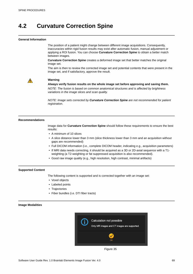
Image Modalities
Figure 35
SPINE PROCEDURES
Software User Guide Rev. 1.0 Brainlab Elements Image Fusion Ver. 4.0 69
Common imaging modalities like CT and MRI with several submodalities are supported fordeformation.The following special modalities and sequence types are not supported:• Previously deformed image sets• RGB images• FA and ADC maps• Phase and velocity maps• Perfusion maps• Spectroscopy images• Gradient calibration scans• FLAWS scans (fluid and white matter suppression)• Subtraction images and projections (Minimum/Maximum Intensity Projections)• Image sets containing burned-in objects
How to Start Curvature Correction Spine
Step
Choose Curvature Correction Spine from the main screen of Content Manager.
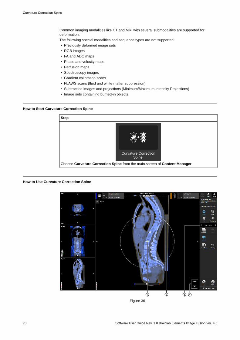
How to Use Curvature Correction Spine
②① ③ ④Figure 36
Curvature Correction Spine
70 Software User Guide Rev. 1.0 Brainlab Elements Image Fusion Ver. 4.0
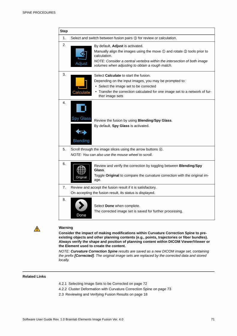
Step
1. Select and switch between fusion pairs ③ for review or calculation.
2. By default, Adjust is activated.Manually align the images using the move ① and rotate ② tools prior tocalculation.NOTE: Consider a central vertebra within the intersection of both imagevolumes when adjusting to obtain a rough match.
3. Select Calculate to start the fusion.Depending on the input images, you may be prompted to:• Select the image set to be corrected• Transfer the correction calculated for one image set to a network of fur-
ther image sets
4.
Review the fusion by using Blending/Spy Glass.By default, Spy Glass is activated.
5. Scroll through the image slices using the arrow buttons ④.NOTE: You can also use the mouse wheel to scroll.
6. Review and verify the correction by toggling between Blending/SpyGlass.Toggle Original to compare the curvature correction with the original im-age.
7. Review and accept the fusion result if it is satisfactory.On accepting the fusion result, its status is displayed.
8.
Select Done when complete.The corrected image set is saved for further processing.
WarningConsider the impact of making modifications within Curvature Correction Spine to pre-existing objects and other planning contents (e.g., points, trajectories or fiber bundles).Always verify the shape and position of planning content within DICOM Viewer/Viewer orthe Element used to create the content.NOTE: Curvature Correction Spine results are saved as a new DICOM image set, containingthe prefix [Corrected]. The original image sets are replaced by the corrected data and storedlocally.
Related Links
4.2.1 Selecting Image Sets to be Corrected on page 724.2.2 Cluster Deformation with Curvature Correction Spine on page 732.3 Reviewing and Verifying Fusion Results on page 18
SPINE PROCEDURES
Software User Guide Rev. 1.0 Brainlab Elements Image Fusion Ver. 4.0 71
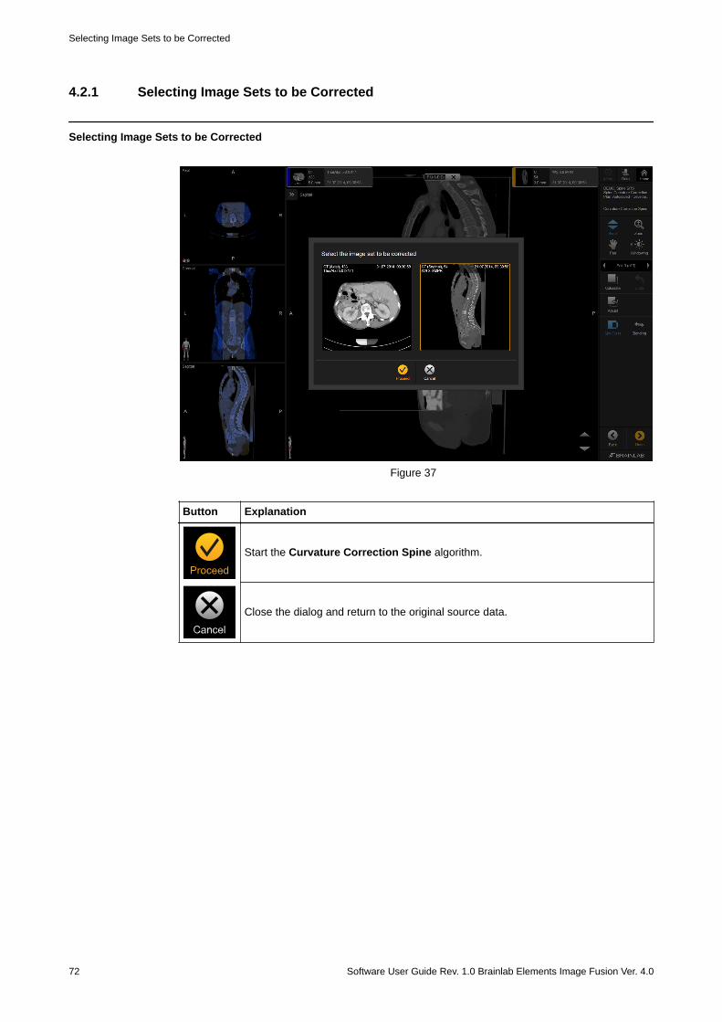
4.2.1 Selecting Image Sets to be Corrected
Selecting Image Sets to be Corrected
Figure 37
Button Explanation
Start the Curvature Correction Spine algorithm.
Close the dialog and return to the original source data.
Selecting Image Sets to be Corrected
72 Software User Guide Rev. 1.0 Brainlab Elements Image Fusion Ver. 4.0
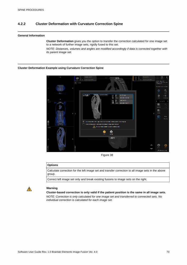
4.2.2 Cluster Deformation with Curvature Correction Spine
General Information
Cluster Deformation gives you the option to transfer the correction calculated for one image setto a network of further image sets, rigidly fused to this set.NOTE: Distances, volumes and angles are modified accordingly if data is corrected together withits parent image set.
Cluster Deformation Example using Curvature Correction Spine
Figure 38
Options
Calculate correction for the left image set and transfer correction to all image sets in the abovegroup.
Correct left image set only and break existing fusions to image sets on the right.
WarningCluster-based correction is only valid if the patient position is the same in all image sets.NOTE: Correction is only calculated for one image set and transferred to connected sets. Noindividual correction is calculated for each image set.
SPINE PROCEDURES
Software User Guide Rev. 1.0 Brainlab Elements Image Fusion Ver. 4.0 73
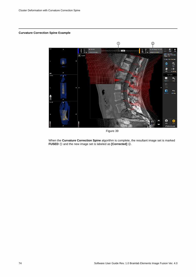
Curvature Correction Spine Example
① ②
Figure 39
When the Curvature Correction Spine algorithm is complete, the resultant image set is markedFUSED ① and the new image set is labeled as [Corrected] ②.
Cluster Deformation with Curvature Correction Spine
74 Software User Guide Rev. 1.0 Brainlab Elements Image Fusion Ver. 4.0
INDEXA
adjust .........................................................................................29adjust function....................................................................... 29,30
Bblending.................................................................................24,26
rigid fusion.............................................................................. 25breaking fusions......................................................................... 33
Cchange image orientation........................................................... 37changing fusion pairs............................................................ 34,35closing Image Fusion................................................................. 40cluster deformation................................................................52,73comparing fusion results............................................. 23,27,49,60contrast clearance analysis........................................................ 54curvature correction spine.......................................................... 69customize fusion pairing.............................................................35
Ddefine alignment......................................................................... 37deformation fusion
corrected image set................................................................ 39deformation map........................................................................ 21distortion correction cranial........................................................ 46documentation............................................................................12
Eelastic deformation .................................................................... 26exit..............................................................................................40
Ffusion
adjust...................................................................................... 29adjustment.............................................................................. 17approval..................................................................................39break fusion....................................................................... 17,33curvature correction spine...................................................... 69customize pairs.......................................................................35distortion correction cranial.....................................................46how to adjust the ROI............................................................. 32manual....................................................................................30manual pairs........................................................................... 35next pair..................................................................................17perform fusion.........................................................................17start a fusion........................................................................... 33undo........................................................................................17
Hhow to
adjust automatic fusions......................................................... 29adjust the ROI.........................................................................32change fusion pairs................................................................ 35change image orientation....................................................... 37close Image Fusion................................................................ 40
define alignment..................................................................... 37display the area of interest..................................................... 32open Image Fusion.................................................................43perform a manual fusion.........................................................30save........................................................................................ 39select fusion pairs...................................................................34use blending........................................................................... 25use blending with elastic deformation.....................................26use curvature correction spine............................................... 70use distortion correction cranial..............................................48use Image Fusion for cranial.................................................. 44use Image Fusion for spine.................................................... 66use spy glass..........................................................................19use virtual iMRI cranial........................................................... 59
Iimage
data transformation.................................................................50modification............................................................................ 43orientation...............................................................................37
Image Fusionclose....................................................................................... 40open........................................................................................43
Image Fusion for cranial.............................................................41Image Fusion for spine...............................................................65
Mmanual fusion............................................................................. 30manual pairing............................................................................35
Oopen Image Fusion.....................................................................43
Ppan............................................................................................. 16
RROI............................................................................................. 32
Ssaving data................................................................................. 39scroll........................................................................................... 16software
closing Image Fusion..............................................................40opening Image Fusion............................................................ 43
spy glassdeformation.............................................................................21how to display area of interest................................................32how to use......................................................................... 19,22original fusion......................................................................... 65rigid fusion.............................................................................. 19
start a fusion...............................................................................33support numbers.......................................................................... 5
INDEX
Software User Guide Rev. 1.0 Brainlab Elements Image Fusion Ver. 4.0 75

Vvirtual iMRI cranial......................................................................57
Wwindowing..............................................................................16,28
Zzoom ..........................................................................................16
INDEX
76 Software User Guide Rev. 1.0 Brainlab Elements Image Fusion Ver. 4.0


brainlab.com
Art-No. 60917-73EN
*60917-73EN*