iej.10.2009
TRANSCRIPT

REVIEW
Apexification: the beginning of its end
G. T.-J. HuangDepartment of Endodontics, Prosthodontics and Operative Dentistry, College of Dental Surgery, University of Maryland, Baltimore,
MD, USA
Abstract
Huang G.T.-J. Apexification: the beginning of its end. Inter-
national Endodontic Journal, 42, 855–866, 2009.
Apexification is a procedure for treating and preserving
immature permanent teeth that have lost pulp vitality.
It contrasts apexogenesis in terms of its outcome in that
apical maturation and normal root thickness cannot be
obtained. Apexification has been a routine practice for
such teeth for many decades, and despite a literature
replete with discussion, including recent artificial
barrier methods with mineral trioxide aggregate, ulti-
mately there has been no major breakthrough to
improve this treatment. Recently, two new clinical
concepts have emerged. One involves a revitalization
approach to achieve tissue generation and regenera-
tion. In this method, new living tissue is expected to
form in the cleaned canal space, allowing continued
root development in terms of both length and thickness.
The other is the active pursuit of pulp/dentine regen-
eration via tissue engineering technology to implant or
re-grow pulps. Although the technology is still at its
infancy, it has the potential to benefit immature
pulpless teeth by allowing continued growth and
maturation. With this understanding, it may be
predicted that apexification will become less needed in
years to come. This study will overview the recent
concept of pulp revitalization in the treatment of
immature teeth with nonvital pulps and the emerging
research on pulp tissue engineering and regeneration.
Keywords: apexification, calcification, pulp/dentine
tissue regeneration, stem cells.
Received 15 July 2008; accepted 26 February 2009
Introduction
Apexification is a procedure to promote the formation
of an apical barrier to close the open apex of an
immature tooth with a nonvital pulp such that the
filling materials can be contained within the root canal
space (Rafter 2005). The capacity of materials such as
calcium hydroxide [Ca(OH)2] to induce the formation
of this calcific barrier at the apex made apexifica-
tion possible and allowed the preservation of many
compromised, immature teeth with nonvital pulps by
endodontic and restorative means. Clinically, when the
pulpal diagnosis of an immature tooth is nonvital,
apexification is undertaken to close the root-end, but
with an understanding that there will be no more
development of the root in terms of apical maturation
and thickening of its dentine walls.
The clinical decision as to whether to perform
apexogenesis or apexification for immature teeth
appears to be clear cut with the teeth deemed to
contain vital pulp tissue being subject to apexogenesis
and teeth deemed to have nonvital pulp tissue receiving
apexification. However, certain clinical observations
reported recently have broken this clear-cut guideline
by showing that apexogenesis may occur in teeth
which have nonvital pulps (Iwaya et al. 2001, Banchs
& Trope 2004, Chueh & Huang 2006). Moreover, it is
Correspondence: George T.-J. Huang, DDS, MSD, DSc, Depart-
ment of Endodontics, Prosthodontics and Operative Dentistry,
College of Dental Surgery, Dental School, University of
Maryland, 650 West Baltimore St, Baltimore, 21201 MD,
USA (Tel.: +410 706 7680; fax: +410 706 3028; e-mail:
doi:10.1111/j.1365-2591.2009.01577.x
ª 2009 International Endodontic Journal International Endodontic Journal, 42, 855–866, 2009 855
likely that many clinicians had been treating some
cases by an apexogenesis approach despite apparent
pulp necrosis, but never reporting the outcome. A new
protocol has been suggested in which a haemorrhage is
induced to fill the canal with blood clot as a scaffold to
allow generation of live tissues in the canal space and
continued root formation (length and wall thickness)
(Banchs & Trope 2004, Thibodeau & Trope 2007,
Thibodeau et al. 2007). Instead of using Ca(OH)2 as the
intracanal medicament between visits to disinfect and
to induce apical barrier formation, an antibiotic paste is
used for the purpose of disinfection only (Iwaya et al.
2001, Banchs & Trope 2004). This new protocol of
treatment coincides with the recent concept of regen-
erative medicine which promotes the research and
practice of tissue regeneration (National Institutes of
Health 2006).
On another front, pulp/dentine tissue may be
regenerated using tissue engineering technologies.
Attempts to regenerate pulp tissue have been consid-
ered impossible until recently and major developments
in two basic research, namely tissue engineering and
stem cell biology. Investigations on dental pulp tissue
engineering began in the late 1990s (Mooney et al.
1996, Bohl et al. 1998, Buurma et al. 1999). The
isolation and characterization of dental pulp stem cells
(DPSCs) (Gronthos et al. 2000), stem cells from
exfoliated deciduous teeth (SHED; Miura et al. 2003)
and stem cells from apical papilla (SCAP) (Sonoyama
et al. 2006) has capitalized the possibility for pulp/
dentine regeneration (Huang et al. 2006, 2008,
Murray et al. 2007a, Cordeiro et al. 2008, Prescott
et al. 2008). Because of the wide-open apex of the
immature tooth, vascularization via apical ingrowth of
blood vessels into an engineered construct containing
stem cells may facilitate a successful regeneration of
pulp/dentine within the canal space (Huang et al.
2008).
This study will overview the shifting concept of
treating immature teeth using revitalization rather
than apexification and the current status of pulp tissue
engineering and regeneration. The review will analyse
the fate of apexification as a first-line treatment for
immature teeth with nonvital pulps and how this is
affected by the shifting paradigm of the management
and the coming era of pulp/dentine tissue regenera-
tion. Again, apexification does not allow generation or
regeneration of vital tissues in the canal space
whereas the revitalization or tissue regeneration
approaches provide a new chance for those affected
teeth to regain biological tissue recovery and growth.
From this point of view, it seems inevitable that in the
interest of patients, apexification may become a less-
desirable and less needed clinical treatment in the
foreseeable future.
Apexification
Immature teeth undergoing apexification are usually
disinfected with irrigants including NaOCl, chlorhexi-
dine, EDTA and iodine–potassium iodide (Rafter 2005).
The canal is then filled with Ca(OH)2 paste for the
purpose of further disinfection and induction of an
apical calcific barrier. Ca(OH)2 is antimicrobial because
of its release of hydroxyl ions which can cause damage
to the bacterial cellular components. The best example
is the demonstration of its effect on lipopolysaccharide
(LPS). Ca(OH)2 chemically alters LPS which affects its
various biological properties (Safavi & Nichols 1993,
1994, Barthel et al. 1997, Nelson-Filho et al. 2002,
Jiang et al. 2003).
Filling the root canal is undertaken normally when
the apical calcific barrier is formed. Without the barrier,
there is nothing against which the traditional gutta-
percha filling material can be condensed. Besides the
fact that Ca(OH)2 functions as a potent disinfectant,
early evidence has suggested osteo-inductive properties
(Mitchell & Shankwalker 1958), although it has been
difficult to demonstrate this effect in vitro (Raquel Assed
Bezerra da et al. 2008). It was considered that the high
pH may be a contributing factor for the induction of
hard tissue formation (Javelet et al. 1985). The time
required for apical barrier formation in apexification
using Ca(OH)2 may be considerable, often as long as
20 months and other conditions such as age and
presence of symptoms or periradicular radiolucencies
may affect the time needed to form an apical barrier.
Refreshing the Ca(OH)2 paste usually takes place every
3 months (Rafter 2005). A number of shortcomings
can be summarized for Ca(OH)2 apexification: (i) long
time-span of the entire treatment; (ii) multiple visits
with heavy demands on patients and carers and
inevitable clinical costs; (iii) increased risk of tooth
fracture using Ca(OH)2 as a long-term root canal
dressing (Cvek 1992, Andreasen et al. 2002). These
drawbacks led to the use of mineral trioxide aggregate
(MTA) to fill the apical end without the need for calcific
barrier formation. In comparison to Ca(OH)2, some
data suggest that MTA appears to be more predictable
with consistent hard-tissue formation based on in vivo
studies in dogs (Shabahang et al. 1999). Using MTA for
apexification may shorten the treatment period with
Apexification, end in sight Huang
International Endodontic Journal, 42, 855–866, 2009 ª 2009 International Endodontic Journal856

more favourable results and improved patient compli-
ance (Maroto et al. 2003, El-Meligy & Avery 2006,
Pace et al. 2007). Many authors and clinicians propose
a one-visit apexification protocol with MTA, which
presents a major advantages over traditional Ca(OH)2methods (Witherspoon & Ham 2001, Steinig et al.
2003). This expedient cleaning and shaping of the root
canal system followed by its apical seal with MTA
makes the rapid placement of a bonded restoration
within the root canal possible, which may prevent
potential fractures of immature teeth.
While advances with MTA and bonded restorations
go some way towards a better outcome, ultimately no
apexification method can produce the outcome that
apexogenesis can achieve, i.e. apical maturation with
increased thickness of the root. As noted above, clinical
experience on the outcome of apexified teeth with thin
and weak roots after successful treatment is that they
are highly susceptible to fracture (Cvek 1992,
Katebzadeh et al. 1998). Therefore, alternative ap-
proaches that allow the increase of root thickness
and/or length should be pursued.
A paradigm shift in the managementof immature teeth
Although the standardized clinical approach for apexo-
genesis or apexification has been widely practiced,
some clinicians inevitably modify their treatment
procedures based on their clinical judgement. Some
reported their cases using alternative approaches, with
three appearing to capture great interest from the
endodontic community. The first, reported by Iwaya
et al. (2001) presented an immature mandibular
premolar with a sinus tract and periradicular radiolu-
cency. During canal preparation, they did not instru-
ment to full working length because the patient felt
discomfort on the insertion of instruments. The canal
was mainly irrigated with NaOCl and hydrogen perox-
ide and further disinfected with antibiotic agents
(metronidazole and ciprofloxacin). Thirty-five months
after the completion of these procedures, they observed
complete maturation of the root apex with thickened
root structure. The tooth also responded positively to
electronic pulp testing. After observing the success of
this alternative approach, the same idea was applied to
treatment of a mandibular premolar having a similar
condition but with more extensive periradicular bone
loss. During careful follow-up to 2 years after the
treatment, complete maturation of the root was
observed with a positive response to cold testing
(Banchs & Trope 2004). Chueh & Huang (2006) later
reported four mandibular premolars in a similar clinical
condition that were treated between 1988 and 2000,
all again demonstrating healing and apical maturation.
These reports raised a great response and encouraged
further reports (Thibodeau & Trope 2007, Hargreaves
et al. 2008, Jung et al. 2008). A more conservative
approach and a shifting paradigm for the treatment of
nonvital immature teeth has thus been proposed
(Huang 2008). Furthermore, the Regenerative End-
odontics Committee of the American Association of
Endodontists has initiated a pilot study by encouraging
endodontists to submit their cases to a data base
(http://www.aae.org/members/revascularizationsurvey.
htm). The study is designed to determine the incidence
and predictors of healing of apical periodontitis in cases
considered to have nonvital pulps when treated by
nonconventional, biologically based revitalization
methods. Currently, the success rate of this type of
approach is only available from an animal study model
(Thibodeau et al. 2007) and a pilot clinical study in
humans (Shah et al. 2008). In the animal model, it was
found that after disinfection of the root canals, 43.9%
of the cases had thickened canal walls, 54.9% had
apical closure and 64.6% had no radiographic evidence
of periapical radiolucency or showed improvement/
healing of previous periapical radiolucencies (Thibo-
deau et al. 2007). The clinical pilot study involving
teeth in 14 patients demonstrated 93% resolution of
periradicular radiolucencies, thickening of lateral den-
tinal walls in 57%, and increased root length in 71%.
None of the cases presented with pain, reinfection or
radiographic enlargement of pre-existing periapical
lesions (Shah et al. 2008). However, due the prelimin-
ary nature of the study, the clinical success rates should
be interpreted with caution (Messer 2008).
Regarding the use of Ca(OH)2 versus antimicrobial
paste, it was suggested that the former may not be
suitable if there is remaining vital pulp tissue in the
canal. The direct contact of Ca(OH)2 paste with the
tissue will induce the formation of a layer of calcific
tissue which may occlude the pulp space, therefore
preventing pulp tissue from regeneration (Huang
2008). Another concern is that Ca(OH)2 may damage
the Hertwig’s epithelial root sheath (HERS) and thereby
destroy its ability to induce the nearby undifferentiated
cells to become ododontoblasts (Banchs & Trope 2004).
The effectiveness of a triple-antibiotic regimen to
disinfect root canal space was first tested and verified
by Sato et al. (1996) and the clinical use of the mixture
has shown success in terms of clinical outcome (Sato
Huang Apexification, end in sight
ª 2009 International Endodontic Journal International Endodontic Journal, 42, 855–866, 2009 857

et al. 1996, Banchs & Trope 2004, Jung et al. 2008).
Whether the three antibiotics originally described (i.e.
metronidazole, minocycline and ciprofloxacin) must be
used for this purpose or if other choices may serve this
purpose requires further investigation.
These clinical case reports demonstrate that despite
the formation of periapical abscesses with extensive
periradicular bone resorption as the result of root canal
infection in immature teeth, conservative treatment
may allow roots to increase in length and thickness or
even reach mature form. One explanation is that the
clinical diagnosis of pulp status is inaccurate and that
some of those teeth must have contained vital tissues in
the apical pulp space despite negative pulp testing and
periapical lucencies. It is also acknowledged that there
is a lack of scientific studies on the diagnosis of pulpal
pathology in permanent teeth with open apices (Camp
2008). It has been considered that, to have continued
root development, HERS and the recently identified
tissue, apical papilla, must be functional (Huang et al.
2008). On the other hand, if the pulp, HERS and apical
papilla are completely lost, the root may still gain some
level of thickness by the ingrowth of cementum from
the periapical areas onto the internal root canal dentine
walls. Additionally, this cementum ingrowth is accom-
panied by periodontal ligament (PDL) and bone tissue
(Kling et al. 1986, Andreasen et al. 1995a,b).
The outcome of guided generation
and regeneration approach
The use of the term ‘revascularization’ was adapted by
Iwaya et al. (2001) to describe the clinical healing of
periapical abscesses and continued root formation in
immature teeth with nonvital pulps. Other authors
adapted the term without questioning until Huang &
Lin (2008) considered that ‘revascularization’ did not
encompass the actual healing and repair process that
takes place in these clinical cases (Huang & Lin 2008).
The term ‘revitalization’ used by earlier studies
attempting to revive tissues in the pulp space would
perhaps describe the phenomenon more accurately
(Nevins et al. 1976).
Pulp space filled with regenerated pulp
The ideal situation is that there is surviving pulp and
apical papilla tissue after root canal disinfection.
Continued root formation to its maturity and an
increased thickness of root dentine may then be
anticipated. The dental papilla at the apex contains
stem cells, ‘SCAP’ that have been recently described to
be more robust stem cells than DPSCs (Sonoyama et al.
2006). The SCAP may survive the infection and retain
the capacity to give rise to new odontoblasts influenced
by HERS, allowing new root dentine to form and root
maturation to proceed to completion. It was speculated
that the surviving DPSCs in the remaining vital pulp
may rebuild the lost pulp tissue in the canal and
differentiate into replacement odontoblasts to substitute
for the damaged primary odontoblasts (Sonoyama et al.
2008). Under this circumstance, one may anticipate
the newly formed odontoblasts from SCAP to produce
root dentine that leads to the apical extension of the
root. Additionally, the existing primary odontoblasts
that survived in the residual pulp tissue and perhaps
some new replacement odontoblasts may continue to
lay down dentine on the dentinal walls, causing the
root to increase its thickness (Fig. 1). Whilst this
explanation is conjecture and requires further basic
and clinical investigation, some data on the recovery of
pulp tissue after tooth replantation appear to support
this speculation (Kling et al. 1986, Ritter et al. 2004).
Pulp space filled with periodontal tissues
In cases where the entire pulp, apical papilla tissues
and the HERS are lost, current understanding is that
self-regeneration of pulp and new dentine formation is
unlikely to occur. There is abundant evidence in the
literature demonstrating that when the pulp tissue of
Apical papilla
Epithelial diaphragm Bone
CementumCementum
DentinPulp
PDL
Odontoblasts
?
Figure 1 Hypothetical pulp regeneration from the remaining
recovered pulp. The question mark indicates that the regen-
eration of pulp into the empty pulp space is uncertain at
present.
Apexification, end in sight Huang
International Endodontic Journal, 42, 855–866, 2009 ª 2009 International Endodontic Journal858

immature teeth with wide-open apices undergoes
complete necrosis but in a sterile environment, other
tissues are capable of filling the canal space. As shown
in the radiographic images (Fig. 2), the replanted
avulsed immature tooth lost pulp vitality but the pulp
space became occupied by the ingrowth of alveolar
bone from the periapex (Kling et al. 1986). There is a
space separating the ingrown bone and the canal
dentinal walls. If one traces this space, it is apparent
that it is continuous with the PDL space on the external
a b
c d
(a)
(b)
Bone
Bone
Dentin
PDL
PDLPDL
PDL
Bone
CementumCementum
Cementum
Figure 2 Ingrowth of periodontal tissue
into pulp space. (a) Radiographs show-
ing an immature tooth 11 (FDI notation)
with an open apex which was
re-implanted and healed. At recalls, the
ingrowth of bone tissue with the PDL
space and lamina dura is evident
[adapted from Kling et al. (1986) with
permission). (b) Illustration depicting the
ingrown tissues of bone, PDL and
cementum into the canal space.
Huang Apexification, end in sight
ª 2009 International Endodontic Journal International Endodontic Journal, 42, 855–866, 2009 859

root surfaces. Lamina dura also appears to have been
established in the ingrown bone occupying the pulp
space. The contents of the pulp space were described by
Holan (1998) as ‘tube-like mineralization’ and follow-
ing histological examination it was interpreted that
secondary dentine and the pulp tissue existed in the
canal space. In fact, this ‘secondary dentine’ was
actually cementum and the ‘pulp tissue’ was PDL.
Careful examination of the characteristics of the ectopic
cementum and PDL in the canal space should be the
basis of further research.
There also seems to have been some degree of
vertical and horizontal extension of the root over time
(Fig. 2). Since the pulp tissue has been entirely lost, it
has not been possible to deposit new dentine, and the
newly acquired calcified tissue has to come from a
tissue source where the cellular components are
capable of proliferating and producing new tissues.
Cementum has the capacity to fulfill this purpose.
Histologically, the hard tissues, bone, cementum and
dentine can usually be distinguished unambiguously
merely for their anatomical location. However, when
ectopic formation of these tissues occurs, discerning
them without specific markers may be difficult. None-
theless, the ingrown hard tissues within the pulp space
have been verified by histological examination, reveal-
ing the deposition of cementum onto the dentine
surface in the canal, extending from the outside surface
of the apex (Nevins et al. 1977, Lieberman & Trow-
bridge 1983). The apical extension of roots resulting
from the apposition of cementum is a normal physio-
logical process. The apposition of calcified cemental
tissue on the internal canal wall also increases the
thickness of the root. A distinct feature of cementum is
its connection with the PDL by Sharpey’s fibres, which
can also be observed in the ingrown tissues in the pulp
space. The ingrowth of periodontal tissue may reach all
the way to the coronal pulp chamber (Nevins et al.
1977, 1978, Ellis et al. 1985, Hitchcock et al. 1985).
Similar results were observed in a dog as a study model
(Thibodeau et al. 2007).
When the pulp space is filled with periodontal tissues,
the situation is totally different from normal because
the pulp space is no longer part of the root canal
system, but part of periapical tissues. If the tooth
becomes reinfected causing destruction of the peri-
odontal tissue in the canal space, the understanding of
a root canal infection to this type of infection cannot be
applied, but perhaps more appropriately that of a
periapical tissue pathosis. It is known that periapical
tissue loss will recover if the source of infection from the
root canal space is eliminated though the establishment
of a biofilm by the invading microbes may complicate
management (de Paz 2007). From this perspective,
disinfection does not have to involve with the aggres-
sive entrance into the canal space, but rather dealing
mainly with the source of infection in the crown.
Currently, there is no case report showing the man-
agement and the outcome of infected canal space that
has been filled with periodontal tissues.
Severe disorganized calcification of the pulp space
Whether the pulp space is filled with regenerated pulp
or periodontal tissues, long-term radiographic observa-
tions demonstrate that the pulp space becomes severely
narrowed or filled with radio-opaque mineralized tissue
over time. Histologically, the mineralizing tissues are
either bone-like or dentine-like (Robertson et al. 1997).
The hard tissues may begin as calcific particles that
have been observed to originate or are closely associ-
ated with blood vessels and perineurium sheaths
(Pashley et al. 2002). Interestingly, these are also the
locations where pulp stem cells are believed to exist (Shi
& Gronthos 2003). Whether these stem cells are
activated by the low-grade inflammation to undergo
osteogenic differentiation is unclear at present. Over
time, these particles merge into larger calcific masses
and obliterate the pulp space (Fig. 3). Although this
calcifying phenomenon within the pulp has been well-
documented, the mechanisms underlying this process
are still elusive.
Prolonged inflammation causes calcification in many
parts of the body, e.g. calcifying tendonitis (Uhthoff
1996). Arthritic joints tend to build osteophytes as a
result of the expanding bone tissue over the damaged
cartilaginous tissues (van der Kraan & van den Berg
2007). Another phenomenon named heterotropic
ossification is characterized by the formation of miner-
alized inclusions within the soft tissues (McCarthy &
Sundaram 2005), e.g. muscles of patients who suffered
from severe trauma to their extremities including
soldiers injured by bomb explosions (Owens et al.
2006). It has been speculated that the causes of such
phenomena include systemic factors and/or local
inflammatory conditions. Stem cells in the muscle have
been investigated for their potential contributory role in
this disease. Deficiencies in osteopontin may lead to
vascular calcification (Giachelli 2005).
There has been an ongoing debate on the relative
benefits of calcified material or gutta-percha filled
canals. From a physiological point of view, calcific
Apexification, end in sight Huang
International Endodontic Journal, 42, 855–866, 2009 ª 2009 International Endodontic Journal860

metamorphosis is a degenerative disease. Moreover,
from a technical perspective, calcified canals pose a
challenge if they need treatment. Most of the literature
does not support endodontic intervention in the case of
mineralized obliteration unless periradicular pathoses is
detected or the involved tooth becomes symptomatic
(Robertson et al. 1997, Gopikrishna et al. 2004). Sur-
gical intervention may be the only option to contain
the infection from the periradicular tissues if calcified
canals are not accessible for nonsurgical root canal
treatment.
Progress on pulp/dentine tissue
engineering and regeneration
The potential of pulp tissue to regenerate lost dentine is
well-known. Direct pulp capping therapy to induce
dentinal bridge formation is practiced on the basis of this
understanding. The use of various cement-based mate-
rials such as Ca(OH)2 and MTA is believed to promote
such activity. Long-term success using MTA for direct
pulp capping has been reported recently (Bogen et al.
2008). The application of recombinant growth factors
to the injured site to enhance the regeneration of
dentine has also been investigated (Rutherford & Gu
2000). Cell-based therapy using isolated pulp cells or
DPSCs, with genetic manipulation to express bone
morphogenic proteins, to augment the generation of
new dentine bridge formation is an additional area of
exploration (Rutherford 2001, Iohara et al. 2004).
When dealing with the initial phases of dentine
destruction where there is minimal damage, applying a
complicated biotechnological approach appears imprac-
tical. When the tooth is further damaged, regeneration
of dentine becomes difficult as it needs a healthy pulp
which may be compromised by the disease. Ideally, the
regenerated dentine should not replace the pulp space.
Two types of pulp regeneration can be considered based
on the clinical situations: (i) partial pulp regeneration
and (ii) de novo synthesis of pulp.
It has been observed that pulpal infection and
inflammation is compartmentalized until the entire
pulp tissue undergoes necrosis (Seltzer et al. 1963,
Trowbridge 2002). Before the end stage, the remaining
pulp tissue may be recoverable and help regenerate the
lost portion. To enhance the regeneration, engineered
pulp tissues may be inserted into the pulp space to
facilitate the entire recovery of pulp tissue and the
generation of new dentine. When the entire pulp tissue
is lost, de novo synthesis of pulp must take place to
regenerate the tissue.
Early efforts on pulp regeneration
Regenerating pulp tissue has been a long quest. Ostby
(1961) studied the tissue re-organization in the canal
space filled with blood clot. It was observed that the
tissue formed in the canal was not pulp but granulation
or fibrous tissues and in some cases the ingrowth of
cementum and bone occurred. Similar findings were
observed by Myers & Fountain (1974) in a primate
study using blood clot as a scaffold. The average
generation of soft connective tissue into the canal was
only 0.1–1.0 mm, although the authors mentioned
(a) (b) (c)
Figure 3 Common feature of pulp
undergoing calcific metamorphosis. (a)
Pulp tissue from a tooth which had been
previously restored with old fillings and
a clinical diagnosis of normal pulp
(arrows indicate mineral deposits that
appear to have been associated with
vascular structures) (b, c) Pulp tissues
from teeth diagnosed with irreversible
pulpitis. Arrows indicate heavy mineral
deposits.
Huang Apexification, end in sight
ª 2009 International Endodontic Journal International Endodontic Journal, 42, 855–866, 2009 861

that teeth with open apices had a few more millimetres
of ingrowth than those with mature apicies (Myers &
Fountain 1974).
It appears that in a natural situation, regeneration of
pulp cannot occur following total loss of pulp tissue.
Pulp cells have been isolated for various studies for
many decades and they have been shown to have the
capacities to differentiate into mineral forming odonto-
blast-like cells in vitro (Tsukamoto et al. 1992, About
et al. 2000, Couble et al. 2000). However, it was not
until it was demonstrated the formation of ectopic
dentine/pulp-like complex in vivo by isolated pulp cells
that the isolation of odontoblast progenitor cells or pulp
stem cells was truly confirmed (Gronthos et al. 2000).
These cells were termed postnatal DPSCs.
Pulp tissue engineering
Before the isolation of DPSCs, pulp regeneration was
tested using modern tissue engineering concepts by
growing pulp cells onto synthetic polymer scaffolds of
polyglycolic acid (PGA) and in vitro and in vivo analyses
performed (Mooney et al. 1996, Bohl et al. 1998,
Buurma et al. 1999). These approaches are basically
a proof-of-principle to test whether cultured pulp cells
can grow well and produce matrix on PGA, and
whether the engineered pulp can be vascularized using
in vivo study models. This approach reflected the
emphasis on providing a three-dimensional structure
for cells to attach to which simulates the in vivo
environment. Using a tooth slice model, generation of
well-vascularized pulp-like tissue has been reported
(Cordeiro et al. 2008, Prescott et al. 2008).
Issues in cell-based pulp tissue engineering
The following questions must be considered when
attempting to engineer and regenerate pulp tissue:
(i) vascularization: can the angiogenesis from the limited
apical blood supply extend to the coronal end if the
entire pulp is to be regenerated? (ii) New odontoblast
formation: can the new odontoblasts form against the
existing dentinal wall that has been chemically
disinfected during the root canal procedures? (iii) New
dentine formation: can the newly differentiated odonto-
blasts produce new dentine and how much would they
produce? (iv) Cell source: autologous cells are still the
best cell source to avoid potential immune rejection.
However, where can one find the cells needed for pulp
regeneration in the clinical setting? These points will
now be discussed in turn.
Vascularization
While vascularization is a universal issue for an
engineered tissue, it is of special concern for pulp tissue
engineering because of the lack of a collateral source of
blood supply. It was considered that the use of
angiogenic inducing factors such as vascular endothe-
lial growth factor (VEGF) could enhance and accelerate
pulp angiogenesis. Alternatively, the insertion of engi-
neered pulp tissue may have to be separated into
multiple steps to allow progressive vascularization
(Huang et al. 2008). The choice of scaffold and the
source of angiogenic factors have become integrated
issues. Artificial synthetic scaffolds such as co-polymer
of d,l-lactide and glycolide can be fabricated with
impregnated growth factors such as VEGF and/or
platelet-derived growth factor (Sheridan et al. 2000,
Richardson et al. 2001, Peters et al. 2002, Kanematsu
et al. 2004, Stiver et al. 2004, Sun et al. 2005). The
size of apical opening would affect the ingrowth of
blood vessels into the engineered pulp tissue. It is
assumed that the larger the opening, the more likely
that angiogenesis can occur. Immature teeth with open
apices are therefore the best candidates for pulp tissue
regeneration.
It is a misconception to adapt the concept of
engineering/regenerating bone for pulp tissue. Certain
scaffolds that have osteo-inductive or conductive prop-
erties and are suitable for bone regeneration, such as
hydroxyapatite and tricalcium phosphate have been
proposed as scaffolds for pulp regeneration. The
misconception is based on the fact that dentine
production has many aspects similar to bone forma-
tion. However, it is important to recognize the key
differences. An obvious one is the anatomic character-
istics. Bone mass contains compact or trabecular bone
and marrow, whereas dentine and pulp in a tooth have
a rigid anatomic location. When regenerating pulp and
dentine, the dentine should be located peripherally to
the pulp, not within it. Therefore, the scaffold that
carries the cells to regenerate pulp and dentine should
not induce dentine formation randomly within the
regenerated pulp.
New odontoblast formation
To address the question whether new odontoblasts can
form on the existing dentine walls, in vitro experiments
have shown that by seeding DPSCs onto the existing
dentine, some cells transformed into odontoblast-like
cells with a cellular process extending into dentinal
tubules (Huang et al. 2006). A tooth slice model has
been utililzed and seeded SHED onto synthetic scaffolds
Apexification, end in sight Huang
International Endodontic Journal, 42, 855–866, 2009 ª 2009 International Endodontic Journal862
of poly-l-lactic acid cast in the pulp chamber of the thin
tooth slice. They observed odontoblast-like cells arising
from the stem cells and localized against the existing
dentine surface in their in vivo study model (Nor 2006,
Cordeiro et al. 2008). From these observations, it
appears that stem cells seeded in the scaffold will be
attracted to the dentinal wall, differentiate into odon-
toblast-like cells and extend their cellular processes into
the dentinal tubules. The mechanism behind this
phenomenon has been speculated to be the released
growth factors such as TGF-b by the dentine, which
attracts and induces the differentiation of odontoblasts
(Huang et al. 2006). Chemical disinfection of the root
canal space may damage these embedded growth
factors. Further investigation is needed to seek for
ways to avoid this potential damage, and positively
promote odontoblast-like colonization.
New dentine formation
The next question is whether these newly formed
odontoblast-like cells will make new dentine. In an
in vivo study model, DPSCs were seeded onto dentine
and the construct implanted into the subcutaneous
space of immunocompromised mice. Deposition of
reparative dentine-like structures by odontoblast-like
cells was observed (Batouli et al. 2003). This finding
suggests the possibility of forming additional new
dentine on existing dentine if new odontoblasts can
emerge. Huang G.T.-J., Shea L.D., Shi S. & Tuan R.S.
(upubl. data) also demonstrated that new dentine-like
or osteodentine structure can deposit onto the existing
dentine throughout the entire canal wall in an in vivo
pulp engineering/regeneration study model.
Cell source
With respect to the cell source, there are several
potential sources to obtain autologous cells for pulp/
dentine tissue regeneration: DPSC, SCAP and SHED.
Immature third molars are one of the best sources for
DPSCs and SCAP. The latter have been shown to be
more potent dental stem cells than DPSCs in terms of
their level of immaturity and potentiality. They give
rise to odontoblast-like cells and make ectopic dentine
in in vivo study models (Sonoyama et al. 2006) . SHED
also produce ectopic dentine in vivo (Miura et al. 2003).
The problem is the availability of this source. Banking
personal teeth for future use appears to be a direction
that must be explored and established to ensure this
availability. Allogenic cells are an alternative and
convenient source. The finding of the immunosuppres-
sive capacity of mesenchymal stem cells to avoid
immuno-rejection provides a great possibility that
allogenic stem cells may be a good source (Pierdome-
nico et al. 2005, Chen et al. 2006). However, in vivo
studies to verify the long-term survival of transplanted
allogenic dental stem cells are lacking.
Prospects
The above analysis points out the potential future fate of
apexification procedures. Such procedures may no
longer be the preferred first option to treat immature
permanent teeth with nonvital pulps. Induced genera-
tion and regeneration of vital tissues in the pulp space
can thicken the root structure leading to a stronger tooth
with a potentially reduced fracture risk. The progress of
pulp/dentine regeneration so far has been promising and
is likely to work in the not so distant future.
There is some concern caused by the uncertainty as
to how pulp regeneration would affect the future of
endodontic practice (Murray et al. 2007b) . One may
anticipate that to feasibly deliver stem cell-based
endodontic therapy for pulp/dentine regeneration in
endodontic practice, an uncomplicated clinical protocol
would need to be established. If not, technology transfer
to the commercial sector would be difficult (Rutherford
2007).
Acknowledgements
This work was supported in part by an Endodontic
Research Grant from the American Association of
Endodontists Foundation (G.T.-J.H.).
Reference
About I, Bottero MJ, de Denato P, Camps J, Franquin JC,
Mitsiadis TA (2000) Human dentin production in vitro.
Experimental Cell Research 258, 33–41.
Andreasen JO, Borum MK, Jacobsen HL, Andreasen FM
(1995a) Replantation of 400 avulsed permanent incisors.
1. Diagnosis of healing complications. Endodontics and Dental
Traumatology 11, 51–8.
Andreasen JO, Borum MK, Jacobsen HL, Andreasen FM
(1995b) Replantation of 400 avulsed permanent incisors.
2. Factors related to pulpal healing. Endodontics and Dental
Traumatology 11, 59–68.
Andreasen JO, Farik B, Munksgaard EC (2002) Long-term
calcium hydroxide as a root canal dressing may increase
risk of root fracture. Dental Traumatology 18, 134–7.
Banchs F, Trope M (2004) Revascularization of immature
permanent teeth with apical periodontitis: new treatment
protocol? Journal of Endodontics 30, 196–200.
Huang Apexification, end in sight
ª 2009 International Endodontic Journal International Endodontic Journal, 42, 855–866, 2009 863
Barthel CR, Levin LG, Reisner HM, Trope M (1997) TNF-alpha
release in monocytes after exposure to calcium hydroxide
treated Escherichia coli LPS. International Endodontic Journal
30, 155–9.
Batouli S, Miura M, Brahim J et al. (2003) Comparison of
stem-cell-mediated osteogenesis and dentinogenesis. Journal
of Dental Research 82, 976–81.
Bogen G, Kim JS, Bakland LK (2008) Direct pulp capping with
mineral trioxide aggregate: an observational study. Journal
of the American Dental Association 139, 305–15.
Bohl KS, Shon J, Rutherford B, Mooney DJ (1998) Role of
synthetic extracellular matrix in development of engineered
dental pulp. Journal of Biomaterials Science. Polymer Edition 9,
749–64.
Buurma B, Gu K, Rutherford RB (1999) Transplantation of
human pulpal and gingival fibroblasts attached to synthetic
scaffolds. European Journal of Oral Sciences 107, 282–9.
Camp JH (2008) Diagnosis dilemmas in vital pulp therapy:
treatment for the toothache is changing, especially in
young, immature teeth. Journal of Endodontics 34, S6–12.
Chen XI, Armstrong MA, Li G (2006) Mesenchymal stem cells
in immunoregulation. Immunology and Cell Biology 84, 413–
21.
Chueh L-H, Huang GTJ (2006) Immature teeth with perira-
dicular periodontitis or abscess undergoing apexogenesis: a
paradigm shift. Journal of Endodontics 32, 1205–13.
Cordeiro MM, Dong Z, Kaneko T et al. (2008) Dental pulp
tissue engineering with stem cells from exfoliated deciduous
teeth. Journal of Endodontics 34, 962–9.
Couble ML, Farges JC, Bleicher F, Perrat-Mabillon B, Boudeulle
M, Magloire H (2000) Odontoblast differentiation of human
dental pulp cells in explant cultures. Calcified Tissue Interna-
tional 66, 129–38.
Cvek M (1992) Prognosis of luxated non-vital maxillary
incisors treated with calcium hydroxide and filled with
gutta-percha. A retrospective clinical study. Endodontics and
Dental Traumatology 8, 45–55.
Ellis E III, Cox CF, Hitchcock R, Baker J (1985) Vital
apicoectomy of the teeth: a 1–4 week histopathological
study in Macaca mulatta. Journal of Oral Pathology 14, 718–
32.
El-Meligy OA, Avery DR (2006) Comparison of apexification
with mineral trioxide aggregate and calcium hydroxide.
Pediatric Dentistry 28, 248–53.
Giachelli CM (2005) Inducers and inhibitors of biomineraliza-
tion: lessons from pathological calcification. Orthodontics and
Craniofacial Research 8, 229–31.
Gopikrishna V, Parameswaran A, Kandaswamy D (2004)
Criteria for management of calcific metamorphosis: review
with a case report. Indian Journal of Dental Research 15, 54–
7.
Gronthos S, Mankani M, Brahim J, Robey PG, Shi S (2000)
Postnatal human dental pulp stem cells (DPSCs) in vitro and
in vivo. Proceedings of the National Academy of Sciences of the
United States of America 97, 13625–30.
Hargreaves KM, Geisler T, Henry M, Wang Y (2008) Regen-
eration potential of the young permanent tooth: what does
the future hold? Journal of Endodontics 34, S51–6.
Hitchcock R, Ellis E III, Cox CF (1985) Intentional vital root
transection: a 52-week histopathologic study in Macaca
mulatta. Oral Surgery, Oral Medicine, Oral Pathology 60,
2–14.
Holan G (1998) Tube-like mineralization in the dental pulp of
traumatized primary incisors. Dental Traumatology 14, 279–
84.
Huang GTJ (2008) A paradigm shift in endodontic manage-
ment of immature teeth: conservation of stem cells for
regeneration. Journal of Dentistry 36, 379–86.
Huang GTJ, Lin LM (2008) Letter to the editor: comments on
the use of the term ‘‘revascularization’’. Journal of Endodon-
tics 34, 511.
Huang GTJ, Sonoyama W, Chen J, Park S (2006) In vitro
characterization of human dental pulp cells: various isola-
tion methods and culturing environments. Cell and Tissue
Research 324, 225–36.
Huang GTJ, Sonoyama W, Liu Y, Liu H, Wang S, Shi S (2008)
The hidden treasure in apical papilla: the potential role in
pulp/dentin regeneration and bioroot engineering. Journal of
Endodontics 34, 645–51.
Iohara K, Nakashima M, Ito M, Ishikawa M, Nakasima A,
Akamine A (2004) Dentin regeneration by dental pulp stem
cell therapy with recombinant human bone morphogenetic
protein 2. Journal of Dental Research 83, 590–5.
Iwaya SI, Ikawa M, Kubota M (2001) Revascularization of an
immature permanent tooth with apical periodontitis and
sinus tract. Dental Traumatology 17, 185–7.
Javelet J, Torabinejad M, Bakland LK (1985) Comparison of
two pH levels for the induction of apical barriers in
immature teeth of monkeys. Journal of Endodontics 11,
375–8.
Jiang J, Zuo J, Chen SH, Holliday LS (2003) Calcium hydroxide
reduces lipopolysaccharide-stimulated osteoclast formation.
Oral Surgery, Oral Medicine, Oral Pathology, Oral Radiology
and Endodontics 95, 348–54.
Jung I-Y, Lee S-J, Hargreaves KM (2008) Biologically based
treatment of immature permanent teeth with pulpal necro-
sis: a case series. Journal of Endodontics 34, 876–87.
Kanematsu A, Yamamoto S, Ozeki M et al. (2004) Collagenous
matrices as release carriers of exogenous growth factors.
Biomaterials 25, 4513–20.
Katebzadeh N, Dalton BC, Trope M (1998) Strengthening
immature teeth during and after apexification. Journal of
Endodontics 24, 256–9.
Kling M, Cvek M, Mejare I (1986) Rate and predictability of
pulp revascularization in therapeutically reimplanted
permanent incisors. Endodontics and Dental Traumatology 2,
83–9.
van der Kraan PM, van den Berg WB (2007) Osteophytes:
relevance and biology. Osteoarthritis and Cartilage 15, 237–
44.
Apexification, end in sight Huang
International Endodontic Journal, 42, 855–866, 2009 ª 2009 International Endodontic Journal864

Lieberman J, Trowbridge H (1983) Apical closure of nonvital
permanent incisor teeth where no treatment was performed:
case report. Journal of Endodontics 9, 257–60.
Maroto M, Barberia E, Planells P, Vera V (2003) Treatment of
a non-vital immature incisor with mineral trioxide aggre-
gate (MTA). Dental Traumatology 19, 165–9.
McCarthy E, Sundaram M (2005) Heterotopic ossification: a
review. Skeletal Radiology 34, 609–19.
Messer HH (2008) To the editor. Journal of Endodontics 34,
1157.
Mitchell DF, Shankwalker GB (1958) Osteogenic potential of
calcium hydroxide and other materials in soft tissue and
bone wounds. Journal of Dental Research 37, 1157–63.
Miura M, Gronthos S, Zhao M et al. (2003) SHED: stem cells
from human exfoliated deciduous teeth. Proceedings of the
National Academy of Sciences of the United States of America
100, 5807–12.
Mooney DJ, Powell C, Piana J, Rutherford B (1996) Engineer-
ing dental pulp-like tissue in vitro. Biotechnology Progress
12, 865–8.
Murray PE, Garcia-Godoy F, Hargreaves KM (2007a) Regen-
erative endodontics: a review of current status and a call for
action. Journal of Endodontics 33, 377–90.
Murray PE, Garcia-Godoy F, Hargreaves KM (2007b) Reply.
Journal of Endodontics 33, 1277.
Myers WC, Fountain SB (1974) Dental pulp regeneration
aided by blood and blood substitutes after experimentally
induced periapical infection. Oral Surgery Oral Medicine, Oral
Pathology 37, 441–50.
National Institutes of Health (2006) Regenerative Medicine.
National Institutes of Health Fact Sheet. Available at: http://
www.nih.gov/about/researchresultsforthepublic/Regen.pdf.
Nelson-Filho P, Leonardo MR, Silva LA, Assed S (2002)
Radiographic evaluation of the effect of endotoxin (LPS) plus
calcium hydroxide on apical and periapical tissues of dogs.
Journal of Endodontics 28, 694–6.
Nevins AJ, Finkelstein F, Borden BG, Laporta R (1976)
Revitalization of pulpless open apex teeth in rhesus mon-
keys, using collagen-calcium phosphate gel. Journal of
Endodontics 2, 159–65.
Nevins A, Wrobel W, Valachovic R, Finkelstein F (1977) Hard
tissue induction into pulpless open-apex teeth using
collagen-calcium phosphate gel. Journal of Endodontics 3,
431–3.
Nevins A, Finkelstein F, Laporta R, Borden BG (1978)
Induction of hard tissue into pulpless open-apex teeth using
collagen-calcium phosphate gel. Journal of Endodontics 4,
76–81.
Nor JE (2006) Tooth regeneration in operative dentistry.
Operative Dentistry 31, 633–42.
Ostby BN (1961) The role of the blood clot in endodontic
therapy. An experimental histologic study. Acta Odontologica
Scandinavica 19, 324–53.
Owens BD, Wenke JC, Svoboda SJ, White DW (2006)
Extremity trauma research in the United States Army.
Journal of the American Academy of Orthopaedic Surgeons 14,
S37–40.
Pace R, Giuliani V, Pini Prato L, Baccetti T, Pagavino G (2007)
Apical plug technique using mineral trioxide aggregate:
results from a case series. International Endodontic Journal 40,
478–84.
Pashley DH, Walton RE, Slavkin HC (2002) Histology and
physiology of the dental pulp, Chapter 2. In: Ingle JI,
Bakland LK, eds. Endodontics, 5th edn. Hamilton, ON,
Canada: BC Decker Inc, pp. 25–38.
de Paz LC (2007) Redefining the persistent infection in root
canals: possible role of biofilm communities. Journal of
Endodontics 33, 652–62.
Peters MC, Polverini PJ, Mooney DJ (2002) Engineering
vascular networks in porous polymer matrices. Journal of
Biomedical Materials Research 60, 668–78.
Pierdomenico L, Bonsi L, Calvitti M et al. (2005) Multipotent
mesenchymal stem cells with immunosuppressive activity
can be easily isolated from dental pulp. Transplantation 80,
836–42.
Prescott RS, Alsanea R, Fayad MI et al. (2008) In vivo
generation of dental pulp-like tissue by using dental pulp
stem cells, a collagen scaffold, and dentin matrix protein 1
after subcutaneous transplantation in mice. Journal of
Endodontics 34, 421–6.
Rafter M (2005) Apexification: a review. Dental Traumatology
21, 1–8.
da Raquel Assed Bezerra S, MA¡rio Roberto L, da LAªa Assed
Bezerra S, Larissa Moreira Spinola de C, Adalberto Luiz R, de
Paulo Tambasco O (2008) Effects of the association between
a calcium hydroxide paste and 0.4% chlorhexidine on the
development of the osteogenic phenotype in vitro. Journal of
Endodontics 34, 1485–9.
Richardson TP, Peters MC, Ennett AB, Mooney DJ (2001)
Polymeric system for dual growth factor delivery. Nature
Biotechnology 19, 1029–34.
Ritter AL, Ritter AV, Murrah V, Sigurdsson A, Trope M (2004)
Pulp revascularization of replanted immature dog teeth after
treatment with minocycline and doxycycline assessed by
laser Doppler flowmetry, radiography, and histology. Dental
Traumatology 20, 75–84.
Robertson A, Lundgren T, Andreasen JO, Dietz W, Hoyer I,
Noren JG (1997) Pulp calcifications in traumatized primary
incisors. A morphological and inductive analysis study.
European Journal of Oral Sciences 105, 196–206.
Rutherford RB (2001) BMP-7 gene transfer to inflamed
ferret dental pulps. European Journal of Oral Sciences 109,
422–4.
Rutherford B (2007) To the editor. Journal of Endodontics 33,
1277.
Rutherford RB, Gu K (2000) Treatment of inflamed ferret
dental pulps with recombinant bone morphogenetic protein-
7. European Journal of Oral Sciences 108, 202–6.
Safavi KE, Nichols FC (1993) Effect of calcium hydroxide on
bacterial lipopolysaccharide. Journal of Endodontics 19, 76–8.
Huang Apexification, end in sight
ª 2009 International Endodontic Journal International Endodontic Journal, 42, 855–866, 2009 865

Safavi KE, Nichols FC (1994) Alteration of biological properties
of bacterial lipopolysaccharide by calcium hydroxide treat-
ment. Journal of Endodontics 20, 127–9.
Sato I, Ando-Kurihara N, Kota K, Iwaku M, Hoshino E (1996)
Sterilization of infected root-canal dentine by topical
application of a mixture of ciprofloxacin, metronidazole and
minocycline in situ. International Endodontic Journal 29, 118–
24.
Seltzer S, Bender IB, Ziontz M (1963) The dynamics of pulp
inflammation: correlations between diagnostic data and
actual histologic findings in the pulp. Oral Surgery, Oral
Medicine, Oral Pathology 16, 969–77.
Shabahang S, Torabinejad M, Boyne PP, Abedi H, McMillan P
(1999) A comparative study of root-end induction using
osteogenic protein-1, calcium hydroxide, and mineral
trioxide aggregate in dogs. Journal of Endodontics 25, 1–5.
Shah N, Logani A, Bhaskar U, Aggarwal V (2008) Efficacy of
revascularization to induce apexification/apexogensis in
infected, nonvital, immature teeth: a pilot clinical study.
Journal of Endodontics 34, 919–25; discussion 1157.
Sheridan MH, Shea LD, Peters MC, Mooney DJ (2000)
Bioabsorbable polymer scaffolds for tissue engineering
capable of sustained growth factor delivery. J Control Release
64, 91–102.
Shi S, Gronthos S (2003) Perivascular niche of postnatal
mesenchymal stem cells in human bone marrow and
dental pulp. Journal of Bone and Mineral Research 18, 696–
704.
Sonoyama W, Liu Y, Fang D et al. (2006) Mesenchymal stem
cell-mediated functional tooth regeneration in swine. PLoS
ONE 1, e79.
Sonoyama W, Liu Y, Yamaza T et al. (2008) Characterization
of the apical papilla and its residing stem cells from human
immature permanent teeth: a pilot study. Journal of
Endodontics 34, 166–71.
Steinig TH, Regan JD, Gutmann JL (2003) The use and
predictable placement of mineral trioxide aggregate in one-
visit apexification cases. Australian Endodontic Journal 29,
34–42.
Stiver SI, Tan X, Brown LF, Hedley-Whyte ET, Dvorak HF
(2004) VEGF-A angiogenesis induces a stable neovascula-
ture in adult murine brain. Journal of Neuropathology and
Experimental Neurology 63, 841–55.
Sun Q, Chen RR, Shen Y, Mooney DJ, Rajagopalan S,
Grossman PM (2005) Sustained vascular endothelial
growth factor delivery enhances angiogenesis and perfusion
in ischemic hind limb. Pharmaceutical Research 22, 1110–6.
Thibodeau B, Trope M (2007) Pulp revascularization of a
necrotic infected immature permanent tooth: case report
and review of the literature. Pediatric Dentistry 29, 47–50.
Thibodeau B, Teixeira F, Yamauchi M, Caplan DJ, Trope M
(2007) Pulp revascularization of immature dog teeth with
apical periodontitis. Journal of Endodontics 33, 680–9.
Trowbridge H (2002) Histology of pulpal inflammation.
Chapter 10. In: Hargreaves KM, Goodis HE, eds. Seltzer
and Bender’s Dental Pulp. Carol Stream, IL, USA: Quintes-
sence Publishing Co., Inc, pp. 227–45.
Tsukamoto Y, Fukutani S, Shin-Ike T et al. (1992) Mineralized
nodule formation by cultures of human dental pulp-derived
fibroblasts. Archives of Oral Biology 37, 1045–55.
Uhthoff HK (1996) Calcifying tendinitis. Annales Chirurgiae et
Gynaecologiae 85, 111–5.
Witherspoon DE, Ham K (2001) One-visit apexification:
technique for inducing root-end barrier formation in apical
closures. Practical Procedures and Aesthetic Dentistry 13,
455–60; quiz 462.
Apexification, end in sight Huang
International Endodontic Journal, 42, 855–866, 2009 ª 2009 International Endodontic Journal866

Polymerization stress, flow and dentine bondstrength of two resin-based root canal sealers
S. F. C. Souza1,2, A. C. Bombana3, C. Francci2, F. Goncalves2, C. Castellan2 & R. R. Braga2
1School of Dentistry, Federal University of Maranhao, Sao Luiz, MA; Departments of 2Dental Materials and 3Restorative Dentistry
University of Sao Paulo, Sao Paulo, SP, Brazil
Abstract
Souza SFC, Bombana AC, Francci C, Goncalves F,
Castellan C, Braga RR. Polymerization stress, flow and
dentine bond strength of two resin-based root canal sealers.
International Endodontic Journal, 42, 867–873, 2009.
Aim To compare two resin-based root canal sealers
(AH Plus and dual cure Epiphany) in terms of flow,
polymerization stress and bond strength to dentine.
Methodology Flow was evaluated by measuring the
diameter of uncured discs of sealer (0.5 mL) after 7 min
compression (20N) between two glass plates (n = 5).
Polymerization stress was monitored for 60 min in
1-mm thick discs bonded to two glass rods (Ø = 5 mm)
attached to a universal testing machine (n = 3). Bond
strength was analyzed through micropush-out test
(n = 10) and failure mode was examined with scan-
ning electron microscope (100· and 2500·). Data
were statistically analyzed using the Student’s t-test
(a = 0.05).
Results Polymerization stress was 0.32 ± 0.07 MPa
for Epiphany self-cure, 0.65 ± 0.08 MPa for Epiphany
light-cure and zero for AH Plus (P < 0.05). Flow data
and bond strength values were 30.9 ± 1.1,
28.6 ± 0.7 mm and 6.3 ± 5.3, 17.8 ± 7.5 MPa for
Epiphany and AH Plus, respectively (P < 0.001).
Failure mode was predominantly cohesive in the sealer
for both materials.
Conclusions Epiphany had higher flow and poly-
merization stress and lower bond strength values to
dentine than AH Plus. In view of these findings it can
be implied that AH Plus would provide a better seal.
Keywords: apical gap, flow, micropush-out, poly-
merization stress, root canal sealer.
Received 3 November 2008; accepted 5 March 2009
Introduction
Complete filling of the root canal system with biocom-
patible and dimensionally stable filling materials is an
important factor in achieving endodontic success
(Sjogren et al. 1990). Gutta-percha in combination
with sealers of different chemical compositions has been
widely used in clinical practice. However, filling com-
pletely the root canals system remains a challenge
despite the large number of techniques and materials
available (Schwartz 2006). Adhesive bonding and resin
cements developed for endodontic use have emerged as
a possibility to improve root canal filling (Weis et al.
2004). In 2004, a new adhesive root filling material,
Epiphany� Root Filling System, was patented by
Pentron Clinical Technologies (Wallingford, CT, USA).
This system contains a polyester-based thermoplastic
root canal core material (Resilon; Resilon Research LLC,
Madison, CT, USA), a dual-cure methacrylate-based
sealer and a self-etching primer. This material can
promote hybridization with the dentine substrate and a
chemical bond with Resilon, improving resistance to
bacterial leakage (Shipper et al. 2004, 2005) and root
fracture (Teixeira et al. 2004a) due to a potential resin
monoblock formation (Teixeira et al. 2004b). Neverthe-
less, an ultrastructural evaluation revealed a weak link
between Resilon and dentine (Tay et al. 2005a).
Methacrylate-based sealers shrink during polymeriza-
tion (Ferracane 2005), generating stress within the
material and at the tooth-restoration interface that can
Correspondence: Dra Soraia de Fatima Carvalho Souza,
Faculdade de Odontologia, Universidade Federal do Maranhao
(UFMA), Av. dos Portugueses s/n, Bacanga, Sao Luis,
MA 65085-580, Brazil (Tel.: +55 98 21098575; e-mail:
doi:10.1111/j.1365-2591.2009.01581.x
ª 2009 International Endodontic Journal International Endodontic Journal, 42, 867–873, 2009 867

lead to gap formation (Carvalho et al. 1996, Braga et al.
2002, De Munck et al. 2005). The magnitude of stress is
influenced by several factors, such as composition and
volume of the material and cavity configuration factor
(factor-C) (Davidson & de Gee 1984, Davidson et al.
1984, Davidson & Feilzer 1997). In composite restora-
tions, the use of low viscosity materials has been
associated with a reduced incidence of marginal gaps
at the tooth/restoration interface (Uno & Asmussen
1991, Peutzfeldt & Asmussen 2004) and better adapta-
tion to cavity walls (Ferdianakis 1998, Fruits et al.
2002). On the other hand, viscosity is directly related to
degree of conversion (Lovell et al. 1999, Sideridou et al.
2002) which, in turn, is a determinant factor on
polymerization stress development (Braga & Ferracane
2002, Stansbury et al. 2005). The high C-factor situa-
tion represented by the filling of root canals may
originate high polymerization stresses (Goracci et al.
2004), exceeding bond strength to root dentine and
causing debonding of the interface for stress relief (Tay
et al. 2005b). Furthermore, resin sealer photoactivation
for immediate coronal sealing hinders the resin viscous
flow and increases stress build-up (Ferracane 2005),
resulting in inappropriate bond strength or gap forma-
tion between sealer and root dentine (Nagas et al. 2007).
The aim of this study was to compare an epoxy- and a
methacrylate-based root canal sealer in terms of several
characteristics involved in apical gap formation. The
null hypothesis was that AH Plus� (Maillefer, Dentsply
Ind. e Com. Ltda., Petropolis, RJ, Brazil) or Epiphany�(Pentron Clinical Technologies, Wallingford, CT, USA)
would show no difference terms of flow, polymerization
stress and dentine bond strength.
Materials and methods
Flow
According to ADA 57 Specification (American National
Standard/American Dental Association, 2000), 0.5 mL
of sealers was mixed and placed using a graduated
syringe, on a glass plate (40 · 40 · 5 mm). After
180 ± 5 s another glass plate was placed on top of the
sealer, followed by load application of 20 N. Then,
10 min after mixing, the load was removed and
maximum and minimum diameters of compressed discs
were measured with a digital caliper with a 0.01 mm
resolution (Mitutoyo MTI Corporation, Tokyo, Japan).
Results were recorded only if both diameters were
uniform and were within 1.0 mm. Flow was calculated
by averaging five specimens.
Polymerization stress
Polymerization stress was determined using an estab-
lished method (Condon & Ferracane 2000, Witzel et al.
2007, Goncalves et al. 2008). One end of two glass rods
(B 5 mm · 13 or 28 mm height) was sand-blasted
with alumina (150–250 lm), silanated (RelyX Ceramic
primer S; 3M ESPE, St Paul, MN, USA) and coated with
a layer of unfilled resin (Adper� Scotchbond Multi-
purpose, bottle 3; 3M ESPE), which was exposed to the
light source with 300 mW cm)2 for 40 s. The non-
treated ends were attached to the opposite fixtures of a
universal testing machine (Model 5565; Instron, Can-
ton, MA, USA), and the distance between the treated
surfaces was adjusted to 1.0 mm. The 28-mm rod was
connected to a crosshead/load cell, whilst the 13-mm
rod was connected to a stainless steel fixture containing
a slot that allowed, when necessary the distal end of the
light-curing guide to contact the rod opposite to the
treated surface which was highly polished. Resin sealer
(19.6 mm3) was inserted between the treated glass
surfaces and formed into a cylinder and excess was
removed. An extensometer (Model 2630–101; Instron)
was attached to the rods in order to monitor specimen
height. The approximation of the glass rods due to
composite shrinkage was registered by the extensom-
eter and caused the crosshead to move in the opposite
direction to restore the initial distance, with 0.01 lmaccuracy. Therefore, the values registered by the load
cell corresponded to the force necessary to maintain
the initial height of the specimen in opposition to
the contraction force exerted by the resin sealer
(Fig. 1).
Three specimens were tested in each experimental
condition at 37 �C, and force development was mon-
itored for 60 min, starting 3 min after mixing. Exper-
imental conditions were AH Plus, Epiphany self-cure
(SC) and Epiphany light-cure (LC). Epiphany-LC was
photoactivated (VIP Junior; BISCO, Schaumburg, IL,
USA) 17 min after mixing with 475 mW cm)2 for 51 s
(24 J cm)2), following manufacturer’s instructions.
Maximum nominal stress (r, in MPa) was calculated
by dividing the maximum contraction force [F (N)] by
the cross-sectional area of the rods (A) as follows:
r ¼ FðNÞAðmm2Þ
Micropush-out bond strengths
Twenty mandibular single-rooted human premolar
teeth with straight root canals, anatomically similar
Physicomechanical properties of endodontic sealers Souza et al.
International Endodontic Journal, 42, 867–873, 2009 ª 2009 International Endodontic Journal868

dimensions, fully developed apices and patency
foramen were collected after patient’s informed consent
had been obtained under a protocol reviewed and
approved by the Ethical Research Committee of Sao
Paulo University (protocol number, 177/05). Teeth
were cleaned and the working length of each root was
established with a size 15 K file (Dentsply Maillefer
Ballaigues, Switzerland) 1.0 mm short of the apical
foramen. Canals were prepared with a crown-down
technique up to size 50 and irrigated with 0.5% NaOCl
after every change of instrument. Five millilitres of 17%
EDTA was used as final rinse to remove canal wall
smear layer. EDTA solution was neutralized with 0.5%
NaOCl and then the canal was rinsed with saline
solution (15 mL) and dried with paper points.
Prepared root canals were randomly (http://www.
random.org) divided into two experimental groups
(n = 10): AH Plus (Dentsply Ind. e Com. Ltda.) and
Epiphany-SC (Pentron Clinical Technologies). Three
disc slices of one-millimetre thick (±0.1 mm) were
obtained after transverse sectioning (Isomet 1000
Precision Saw; Buehler Ltd., Lake Bluff, IL, USA) the
apical 5.0 mm of each root under water cooling. The
thickness of each root slice was measured by means of
a digital caliper (Mitutoyo MTI Corporation, Tokyo,
Japan). The diameters of each apical and cervical slice
were photographed by a digital camera (Q-Color 5;
Olympus America Inc., Center Valley, PA, USA)
attached to a stereomicroscope (SZ61; Olympus Amer-
ica Inc., Miami, FL, USA) and was measured using
Image J software (http://rsb.info.nih.gov/ij/; National
Institute of Health) under 25· magnification. Speci-
mens with noncircular shape were discarded to avoid
nonuniform stress distributions during testing, resulting
in approximately 25 slices per group. Endodontic sealers
were mixed according to manufacturer’s instructions
and used to fill the entire root canal space. Prior to filling
with Epiphany sealer, root canal dentine was etched for
30 s with Epiphany primer. Specimens were stored for
72 h at 37 �C and 100% relative humidity.
For the micropush-out test, a compressive load was
applied to the specimen via a cylindrical stainless steel
punch attached to a universal testing machine (Kratos
Dinamometros, Embu, SP, Brazil). For each specimen, a
punch tip 0.2 mm smaller than its apical diameter was
selected and positioned such that it touched only the
sealer and did not stress the surrounding root canal
walls. The apical aspect of the each specimen was
positioned facing the punch tip. Loading was performed
at a crosshead speed of 0.5 mm min)1 until the sealer
was dislodged from the root slice. Tensile bond strength
of each slice was calculated as the force (N) of failure
divided by the bonded cross-sectional surface area and
expressed in MPa (Patierno et al. 1996).
Failure mode analysis
For scanning electron microscope (SEM) observation
(100· and 2500·, LEO Stereoscan 440, Electron
Microscopy Ltd., Cambridge, UK) micropush-out spec-
imens were cut longitudinally and root segments were
covered with platinum (Coating System MED 020;
BAL-TEC AG, Balzers, Liechtenstein). To estimate the
percentage of free substrate the interface area was
divided into eight segments. This approach, suggested
by Fowler et al. (1992), was used to classify failure
mode as: (‡75%); cohesive within sealer (£25%)
adhesive-cohesive (>25% to <75%).
Statistical analysis
Data from bond strength to dentine, flow and polymer-
ization stress were analyzed using the Student’s t-test.
For the bond strength test each tooth derived one single
value. The level of significance was fixed at 5%.
1
2
3
4
5
Figure 1 Schematic representation of the experimental set-up
used for polymerization stress determination: (1) fixture
conectect to the load cell; (2) long glass rod; (3) short glass
rod; (4) stainless steel fixture with a slot to allow for the
positioning of the light guide in contact with the glass rod; (5)
extensometer.
Souza et al. Physicomechanical properties of endodontic sealers
ª 2009 International Endodontic Journal International Endodontic Journal, 42, 867–873, 2009 869

Results
Table 1 summarizes average and SD of the micropush-
out test and flow of both sealers. Epiphany presented
significantly high flow than AH Plus (P < 0.001). A
significant difference was detected between polymeri-
zation stress for Epiphany-SC (0.32 ± 0.07 MPa) and
Epiphany-LC (0.65 ± 0.08 MPa) as shown in Fig. 2
(P < 0.05). Epiphany-SC started to generate stress
20 min after mixing. Epiphany-LC was photoactivated
after 17 min from the beginning of the test, when an
abrupt increase on polymerization stress curve
occurred. AH Plus revealed zero polymerization stress
values during 60 min, and for this reason was excluded
from statistical analysis.
For the micropush-out test Epiphany-SC had lower
values when compared with AH Plus (P < 0.001).
Failure mode distribution is shown in Fig. 3: 79.2%
cohesive within sealer and 20.8% adhesive for AH Plus,
78.3% cohesive within sealer and 21.7% adhesive-
cohesive for Epiphany-SC.
Discussion
Apical gap formation is influenced by local factors such
as substrate morphology (Wu et al. 1998, Ferrari et al.
2000, Mjor et al. 2001), C-factor (Goracci et al. 2004,
Tay et al. 2005b), and also material-related factors
such as physical properties of sealers (i.e. flow,
polymerization contraction) (Bergmans et al. 2005,
Braga et al. 2005) and bond strength to dentine
(Tagger et al. 2002, Bouillaguet et al. 2003). This
study assessed the possible relationship between flow,
polymerization stress and bond strength of AH Plus and
Epiphany sealers with apical gap formation.
The fact that no stress development was observed for
AH Plus up to 60 min after mixing agrees with the
manufacturer information that states a setting time of
8 h at 37 �C. However, running the polymerization
stress test for such long periods is impractical. Notwith-
standing, this information is interesting for comparative
purposes with the other sealer evaluated. For Epiphany,
polymerization stress tests were performed for both
curing modes: self-cured, relying only on the peroxide-
amine reaction and dual-cured. Epiphany was tested in
SC mode because clinically the light from photoactiva-
tion does not reach the middle or apical root regions
(Hiraishi et al. 2005). The increased polymerization
time in SC mode allows materials to flow in a pre-gel
state, which could provide stress relief at the dentine/
resin interface (Braga et al. 2002, Braga & Ferracane
2004), and be advantageous for this material. However,
polymerization stress when light-curing was used
(Epiphany-LC) doubled when compared with Epiph-
any-SC (Fig. 2; P < 0.05). This finding is related to an
increase in polymerization rate caused by light activa-
tion. Nagas et al. (2007) suggested that a decreased
polymerization time can adversely affect Epiphany bond
strength to dentine. In fact, one could speculate that an
Table 1 Mean values and standard deviations of bond
strength to dentine and flow for AH Plus� and Epiphany�sealers
Groups Micropush-out (MPa) Flow (mm)
AH Plus 17.8 (7.5)a 28.6 (0.7)b
Epiphany 6.3 (5.3)b 30.9 (1.1)a
Different letters on the same column show statistically signif-
icant differences (P < 0.001).
Figure 2 Polymerization stress (MPa) as a function of time (s)
of Epiphany self-cure (SC) and light-cure (LC).
Figure 3 Failure mode distribution for experimental groups
(%).
Physicomechanical properties of endodontic sealers Souza et al.
International Endodontic Journal, 42, 867–873, 2009 ª 2009 International Endodontic Journal870

increased polymerization rate conferred by light activa-
tion can restrict the chances for polymerization stress
release during the pre-gel state (Tay et al. 2005b).
In theory, total bond strength is the sum of the
strengths of resin tags, hybrid layer and surface
adhesion (Pashley et al. 1995). The low viscosity and
hydrophilic nature of resin-based sealers in association
with pressure caused by condensation technique
allowed the sealer to infiltrate into dentinal tubules,
forming long tags and secondary branchings (Bergmans
et al. 2005, Tay et al. 2005a) In this study, both resin
sealers differed in flow (P < 0,001; Table 1), and both of
them exceeded specification 57 of American National
Standard/American Dental Association (2000). Despite
that, Tay et al. (2005a) showed in SEM and Transmis-
sion Electron Microscope (TEM) the loss of integrity at
dentine/Epiphany sealer and gutta-percha/AH Plus
sealer interfaces. These gaps, presumably created by
polymerization contraction forces (Tay et al. 2005b),
suggest that hybrid layer and long tags do not guaran-
tee the absence of gaps (Bergmans et al. 2005).
Bond strength between endodontic cements and
dentine may be an important property to provide a
seal (Tagger et al. 2002). Micropush-out values for
Epiphany were lower than for AH Plus (P < 0.001;
Table 1). Epiphany polymerization stress may have
contributed to its lower bond strength value. The
amount of stress associated with shrinkage may result
in separation of resin-based sealer and dentinal walls,
and consequently, bond strength values of this inter-
face would decrease (Hiraishi et al. 2005). In this study,
bond strength results for Epiphany sealer are compa-
rable with other experiments that showed values
between 0.32 and 3.73 MPa (Gesi et al. 2005, Ungor
et al. 2006, Fisher et al. 2007, Sly et al. 2007, Kaya
et al. 2008, Lawson et al. 2008, Lee et al. 2008)
though towards the high end range. Although filling
the root canal only with the sealer does not accurately
represent the clinical situation, this experimental model
was chosen because it represents a worst case scenario,
as polymerization stress development is directly related
to the volume of shrinking material (Tay et al. 2005b).
Moreover, by not using gutta-percha and resilon cones,
it can be assured that the tested interface is comprised
of sealer and dentine only.
Epiphany-LC was not included in the micropush-out
test because the study was designed to simulate the
clinical conditions found at the apical third of the root
canal, where the effect of light-curing is likely to be zero.
It is reasonable to speculate that, when used in SCmode,
the sealer does not totally polymerize. The incomplete
polymerization can impair cement mechanical proper-
(a) (b)
(c) (d)
Figure 4 Representative scanning electron microscope (SEM) micrographs of failure mode for AH Plus� (a and b) and Epiphany�(c and d): (a) sealer cohesive failure showing dentine surface recovered by a thick organic matrix layer with different sizes fillers; (b)
adhesive failure showing clean dentine surface only with small fillers and dentinal tubules with organic matrix tags; (c) sealer
cohesive failure indicating dentine surface recovered by an organic matrix layer with granular small fillers, and major fillers with a
thin plaque format, and also some empty spaces; (d) cohesive and adhesive failure demonstrating dentine surface covered by
Epiphany primer and some sealers fragments with fillers closing total or partially dentinal tubules (pointer).
Souza et al. Physicomechanical properties of endodontic sealers
ª 2009 International Endodontic Journal International Endodontic Journal, 42, 867–873, 2009 871

ties and chemical stability (Braga et al. 2002). In fact,
failure mode analysis revealed a high incidence of sealer
cohesive failure for Epiphany (Figs 3 and 4).
The integrity loss on dentine/Epiphany interface can
be explained by comparing its bond strength to dentine
with stress generated during the polymerization con-
traction. Apparently, shrinkage stress was high enough
to surpass bond strength (Bouillaguet et al. 2003, Tay
et al. 2005a). The apparently negligible polymerization
stress values determined in the mechanical test (Fig. 2)
might be of a much higher magnitude in the root canal,
where geometric shape and material confinement are
obstacles for stress release. According to Tay et al.
(2005b), C-factor of adhesive bonding root filling
materials in root canals is highly unfavourable, chal-
lenging the concept of total bonding in root canals.
Conclusion
The null hypothesis was rejected for the three variables
analyzed. Epiphany had higher flow, lower bond
strength to dentine and also developed higher poly-
merization stress than AH Plus. Within the limitations
of this laboratory study and in view of the results it can
be speculated that, clinically, a better interfacial sealing
could be expected with AH Plus. The higher bond
strength to dentine obtained with AH Plus can be
partially explained by its lower polymerization stress.
Moreover, its higher viscosity compared with Epiphany
did not seem to impair its bond strength.
Acknowledgements
This study was partially supported by CAPES
(Coordenacao de Aperfeicoamento de Pessoal de Nıvel
Superior) Institutional Qualification Program (PQI no.:
0090/03–4). The authors are grateful to Flavia Rodri-
gues for providing the polymerization stress test diagram.
References
American National Standard/American Dental Association,
Council on Scientific Affairs (2000) Specification No 57 for
Endodontic Sealing Material. Standards Committee on Dental
Products. Chicago, IL: ANSI/ADA.
Bergmans L, Moisiadis P, De Munck J, Van Meerbeek B,
Lambrechts P (2005) Effect of polymerization shrinkage on
the sealing capacity of resin fillers for endodontic use. The
Journal of Adhesive Dentistry 7, 321–9.
Bouillaguet S, Troesch S, Wataha JC, Krejci I, Meyer JM,
Pashley DH (2003) Microtensile bond strength between
adhesive cements and root canal dentin. Dental Materials
19, 199–205.
Braga RR, Ferracane JL (2002) Contraction stress related to
degree of conversion and reaction kinetics. Journal of Dental
Research 81, 114–8.
Braga RR, Ferracane JL (2004) Alternatives in polymerization
contraction stress management. Critical Reviews in Oral
Biology and Medicine 15, 176–84.
Braga RR, Cesar PF, Gonzaga CC (2002) Mechanical proper-
ties of resin cements with different activation modes. Journal
of Oral Rehabilitation 29, 257–62.
Braga RR, Ballester RY, Ferracane JL (2005) Factors involved
in the development of polymerization shrinkage stress in
resin-composites: a systematic review. Dental Materials 21,
962–70.
Carvalho RM, Pereira JC, Yoshiyama M, Pashley DH (1996) A
review of polymerization contraction: the influence of stress
developmentversusstressrelief.OperativeDentistry21,17–24.
Condon JR, Ferracane JL (2000) Assessing the effect of
composite formulation on polymerization stress. Journal of
American Dental Association 131, 497–503.
Davidson CL, de Gee AJ (1984) Relaxation of polymerization
contraction stresses by flow in dental composites. Journal of
Dental Research 63, 146–8.
Davidson CL, Feilzer AJ (1997) Polymerization shrinkage and
polymerization shrinkage stress in polymer-based restor-
atives. Journal of Dentistry 25, 435–40.
Davidson CL, de Gee AJ, Feilzer A (1984) The competition
between the composite-dentin bond strength and the
polymerization contraction stress. Journal of Dental Research
63, 1396–9.
De Munck J, Van Landuyt K, Peumans M et al. (2005) A
critical review of the durability of adhesion to tooth
tissue: methods and results. Journal of Dental Research 84,
118–32.
Ferdianakis K (1998) Microleakage reduction from newer
esthetic restorative materials in permanent molars. The
Journal of Clinical Pediatric Dentistry 22, 221–9.
Ferracane JL (2005) Developing a more complete understand-
ing of stresses produced in dental composites during
polymerization. Dental Materials 21, 36–42.
Ferrari M, Mannocci F, Vichi A, Cagidiaco MC, Mjor IA (2000)
Bonding to root canal: structural characteristics of the
substrate. American Journal of Dentistry 13, 255–60.
Fisher MA, Berzins DW, Bahcall JK (2007) An in vitro
comparison of bond strength of various obturation materials
to root canal dentin using a push-out test design. Journal of
Endodontics 33, 856–8.
Fowler CS, Swartz ML, Moore BK, Rhodes BF (1992) Influence
of selected variables on adhesion testing. Dental Materials 8,
265–9.
Fruits TJ, VanBrunt CL, Khajotia SS, Duncanson MG Jr (2002)
Effect of cyclical lateral forces on microleakage in cervical
resin composite restorations. Quintessence International 33,
205–12.
Physicomechanical properties of endodontic sealers Souza et al.
International Endodontic Journal, 42, 867–873, 2009 ª 2009 International Endodontic Journal872

Gesi A, Raffaelli O, Goracci C, Pashley DH, Tay FR, Ferrari M
(2005) Interfacial strength of Resilon and gutta-percha to
intraradicular dentin. Journal of Endodontics 31, 809–13.
Goncalves F, Pfeifer CS, Meira JB, Ballester RY, Lima RG, Braga
RR (2008) Polymerization stress of resin composites as a
function of system compliance. Dental Materials 24, 645–52.
Goracci C, Tavares AU, Fabianelli A et al. (2004) The adhesion
between fiber posts and root canalwalls: comparison between
microtensile and push-out bond strength measurements.
European Journal of Oral Sciences 112, 353–61.
Hiraishi N, Papacchini F, Loushine RJ et al. (2005) Shear bond
strength of Resilon to a methacrylate-based root canal
sealer. International Endodontic Journal 38, 753–63.
Kaya BU, Kececi AD, Orhan H, Belli S (2008) Micropush-out
bond strengths of gutta-percha versus thermoplastic
synthetic polymer-based systems: an ex-vivo study. Interna-
tional Endodontic Journal 41, 211–8.
Lawson MS, Loushine B, Mai S et al. (2008) Resistance of a 4-
META-containing, methacrylate-based sealer to dislocation
in root canals. Journal of Endodontics 34, 833–7.
Lee BS, Lai EH, Liao KH, Lee CY, Hsieh KH, Lin CP (2008) A
novel polyurethane-based root canal-obturation material
and urethane-acrylate-based root canal sealer-part 2: eval-
uation of push-out bond strengths. Journal of Endodontics 34,
594–8.
Lovell LG, Stansbury JW, Syrpes DC, Bowman CN (1999)
Effects of composition and reactivity on the reaction kinetics
on dimethacrylate copolymerizations. Macromolecules 32,
3913–21.
Mjor IA, Smith MR, Ferrari M, Mannocci F (2001) The
structure of dentine in the apical region of human teeth.
International Endodontic Journal 34, 346–53.
Nagas E, Cehreli ZC, Durmaz V, Vallittu PK, Lassila LV (2007)
Regional push-out bond strength and coronal microleakage
of Resilon after different light-curing methods. Journal of
Endodontics 33, 1464–8.
Pashley DH, Ciucchi B, Sano H, Carvalho RM, Russell CM
(1995) Bond strength versus dentine structure: a modelling
approach. Archives of Oral Biology 40, 1109–18.
Patierno JM, Rueggeberg FA, Anderson RW, Weller RN,
Pashley DH (1996) Push-out strength and SEM evaluation
of resin composite bonded to internal cervical dentin.
Endodontic Dental Traumatolology 12, 227–36.
Peutzfeldt A, Asmussen E (2004) Determinants of in vitro gap
formation of resin composites. Journal of Dentistry 32, 109–
15.
Schwartz RS (2006) Adhesive dentistry and endodontics. Part
2: bonding in the root canal system-the promise and the
problems: a review. Journal of Endodontics 32, 1125–34.
Shipper G, Orstavik D, Teixeira FB, Trope M (2004) An
evaluation of microbial leakage in roots filled with a
thermoplastic synthetic polymer-based root canal filling
material (Resilon). Journal of Endodontics 30, 342–7.
Shipper G, Teixeira FB, Arnold RR, Trope M (2005) Periapical
inflammation after coronal microbial inoculation of dog
roots filled with gutta-percha or resilon. Journal of Endodon-
tics 31, 91–6.
Sideridou I, Tserki V, Papanastasiou G (2002) Effect of
chemical structure on degree of conversion in light-cured
dimethacrylate-based dental resins. Biomaterials 23, 1819–
29.
Sjogren U, Hagglund B, Sundqvist G, Wing K (1990) Factors
affecting the long-term results of endodontic treatment.
Journal of Endodontics 16, 498–504.
Sly MM, Moore BK, Platt JA, Brown CE (2007) Push-out bond
strength of a new endodontic obturation system (Resilon/
Epiphany). Journal of Endodontics 33, 160–2.
Stansbury JW, Trujillo-Lemon M, Lu H, Ding X, Lin Y, Ge J
(2005) Conversion-dependent shrinkage stress and
strain in dental resins and composites. Dental Materials 21,
56–67.
Tagger M, Tagger E, Tjan AH, Bakland LK (2002) Measure-
ment of adhesion of endodontic sealers to dentin. Journal of
Endodontics 28, 351–4.
Tay FR, Loushine RJ, Weller RN et al. (2005a) Ultrastructural
evaluation of the apical seal in roots filled with a polycap-
rolactone-based root canal filling material. Journal of
Endodontics 31, 514–9.
Tay FR, Loushine RJ, Lambrechts P, Weller RN, Pashley DH
(2005b) Geometric factors affecting dentin bonding in root
canals: a theoretical modeling approach. Journal of Endodon-
tics 31, 584–9.
Teixeira FB, Teixeira EC, Thompson JY, Trope M (2004a)
Fracture resistance of roots endodontically treated with a
new resin filling material. Journal of American Dental
Association 135, 646–52.
Teixeira FB, Teixeira EC, Thompson J, Leinfelder KF, Trope M
(2004b) Dentinal bonding reaches the root canal system.
Journal of Esthetic Restorative Dentistry 16, 348–54.
Ungor M, Onay EO, Orucoglu H (2006) Push-out bond
strengths: the Epiphany-Resilon endodontic obturation sys-
tem compared with different pairings of Epiphany, Resilon,
AH Plus and gutta-percha. International Endodontic Journal
39, 643–7.
Uno S, Asmussen E (1991) Marginal adaptation of a restor-
ative resin polymerized at reduced rate. Scandinavian Journal
Dental Research 99, 440–4.
Weis MV, Parashos P, Messer HH (2004) Effect of obtura-
tion technique on sealer cement thickness and dentinal
tubule penetration. International Endodontic Journal 37,
653–63.
Witzel MF, Ballester RY, Meira JB, Lima RG, Braga RR (2007)
Composite shrinkage stress as a function of specimen
dimensions and compliance of the testing system. Dental
Materials 23, 204–10.
Wu MK, de Gee AJ, Wesselink PR (1998) Effect of tubule
orientation in the cavity wall on the seal of dental filling
materials: an in vitro study. International Endodontic Journal
31, 326–32.
Souza et al. Physicomechanical properties of endodontic sealers
ª 2009 International Endodontic Journal International Endodontic Journal, 42, 867–873, 2009 873
Evaluation of the cost-effectiveness of root canaltreatment using conventional approaches versusreplacement with an implant
M. W. Pennington1, C. R. Vernazza2, P. Shackley1,3, N. T. Armstrong1, J. M. Whitworth2 &J. G. Steele2
1Institute of Health and Society; 2School of Dental Sciences, Newcastle University; and 3Sheffield Vascular Institute, University of
Sheffield, Sheffield, UK
Abstract
Pennington MW, Vernazza CR, Shackley P,
Armstrong NT, Whitworth JM, Steele JG. Evaluation of
the cost-effectiveness of root canal treatment using conven-
tional approaches versus replacement with an implant. Inter-
national Endodontic Journal, 42, 874–883, 2009.
Aim To evaluate the cost-effectiveness of root canal
treatment for a maxillary incisor tooth with a pulp
infection, in comparison with extraction and replace-
ment with a bridge, denture or implant supported
restoration.
Methodology A Markov model was built to simu-
late the lifetime path of restorations placed on the
maxillary incisor following the initial treatment deci-
sion. It was assumed that the goal of treatment was
the preservation of a fixed platform support for a
crown without involving the adjacent teeth. Conse-
quently, the model estimates the lifetime costs and the
total longevity of tooth and implant supported crowns
at the maxillary incisor site. The model considers the
initial treatment decisions, and the various subsequent
treatment decisions that might be taken if initial
restorations fail.
Results Root canal treatment extended the life of the
tooth at an additional cost of £5–8 per year of tooth life.
Provision of orthograde re-treatment, if the root canal
treatment fails returns further extension of the expected
life of the tooth at a cost of £12–15 per year. Surgical
re-treatment is not cost-effective; it is cheaper, per year,
to extend the life of the crown by replacement with a
single implant restoration if orthograde endodontic
treatment fails.
Conclusion Modelling the available clinical and cost
data indicates that, root canal treatment is highly cost-
effective as a first line intervention. Orthograde
re-treatment is also cost-effective, if a root treatment
subsequently fails, but surgical re-treatment is not.
Implants may have a role as a third line intervention if
re-treatment fails.
Keywords: cost-effectiveness, decision analysis,
implant, Markov, root canal treatment.
Received 16 September 2008; accepted 17 March 2009
Introduction
Clinical decisions could be consistent and straightfor-
ward, if they were informed by unequivocal evidence,
supported by clear and accepted guidelines, and if the
recommended actions were universally acceptable to
patients and care providers. But few areas of practice
are so clear-cut. Patients are not always equipped with
the information they need to make rational decisions
on their short and long-term care, and healthcare
agencies might equally be ill-equipped to advise on best
actions for the short and long term. As a consequence,
patients may submit to the paternalistic decision-
making of a healthcare professional (Kaba & Sooria-
kumaran 2007) whose priorities may be expected to be
objective, consistent and based on the same values as
their own. But observations from medicine and
dentistry suggest that the decisions of healthcare
Correspondence: Mark W. Pennington, MSc, PhD, Research
Associate, Institute of Health and Society, Newcastle Univer-
sity, 21 Claremont Place, Newcastle upon Tyne NE2 4AA, UK
(Tel.: +44 191 222 3544; fax: +44 191 222 6043; e-mail:
doi:10.1111/j.1365-2591.2009.01582.x
International Endodontic Journal, 42, 874–883, 2009 ª 2009 International Endodontic Journal874

professionals themselves may be highly variable, even
in the case of relatively simple interventions (Dome-
jean-Orliaguet et al. 2004, Lanning et al. 2005, van der
Sanden et al. 2005, Calnan et al. 2007, Tickle et al.
2007), and influenced by a number of personal,
educational and economic considerations (McColl et al.
1999, Brennan & Spencer 2006).
The picture is complicated further in the case of
complex interventions, and interventions that may
not be the final solution within the lifetime of the
patient. Here, the decision-making process may be
limited to a consideration of the ‘next step’, and
informed by short-term ‘success rates’, assessment of
immediate costs, or of the willingness of the patient to
pay for that individual step. Rarely is the decision-
making process informed by a detailed understanding
of the relative lifespan of alternative interventions or
the ongoing costs, both financial and otherwise
(White et al. 2006, Balevi 2008), which may flow
from a particular treatment decision. Restorative
dental treatments are an example of such an inter-
vention, and if patients faced with treatment decisions,
or healthcare providers stewarding finite resources are
to make properly informed decisions, they must be
presented with information on cost and outcome
which they understand and which accounts for the
long-term.
The uncertainties inherent in modelling the costs of
combinations of interventions over a lifetime require a
fundamentally different approach to the use of evidence
to that, with which most clinicians are comfortable.
Decision analytic modelling provides a rational frame-
work for decision making based on expected costs and
outcomes (Raiffa 1968). Many decision analytic models
are based on Markov modelling, a mathematical means
of investigating stochastic or random events over time
(Sonnenberg & Beck 1993). Such modelling lends itself
well to the study of long-term medical conditions,
defining a clear starting point or condition, and
identifying a number of states into which the individual
may or may not move at defined points in the future.
The probability of remaining in the starting condition
or moving to an alternative state is informed by best
outcome and survival data, and the costs of initial and
future interventions estimated from professional
sources.
Markov models are increasingly used in evaluating
the long-term cost effectiveness of clinical interventions
from the chemoprevention of prostatic cancer to the
management of heart failure (Chan et al. 2008, Svatek
et al. 2008, Takao et al. 2008).
By contrast, the economic models applied to dentistry
have generally been quite simple decision trees (Mil-
eman & van den Hout 2003) or Markov models
(Edwards et al. 1999) extrapolating over a fixed num-
ber of years or the assumed lifetime of a specified
intervention (for example, a dental restoration), rather
than over the lifetime of the patient.
Whilst previous publications have investigated the
costs of dental treatments over a fixed time span
(Bragger et al. 2005), as far as the authors are aware,
this report represents the first attempt to provide a
definitive examination of the cost effectiveness of
common dental interventions and look at all realistic
options that flow from this over the lifetime of a
patient. The starting point of the Markov model is a
common clinical scenario; a damaged and irreversibly
pulpitic maxillary central incisor tooth, where initial
treatment options include root canal treatment and
restoration, or extraction and prosthetic replacement.
The model explores the long-term consequences and
cost effectiveness of initial and subsequent decisions
for individuals at different ages. The question at the
heart of this investigation is whether root canal
treatment and restoration of a damaged maxillary
central incisor is a legitimate and cost-effective inter-
vention over the lifetime of an adult patient, and in
comparison with the alternatives of extraction
followed by either a conventional or an implant-
supported restoration.
Methods
Building the model
For this study, a Markov model was built with TreeAge
decision analysis software (TreeAge Software Inc.,
Williamstown, MA, USA, http://www.treeage.com/
index.htm).
The starting point was a damaged, irreversibly
pulpitic maxillary central incisor in an otherwise
healthy adult male of varying age. The loss of coronal
tooth tissue was defined as sufficient to require resto-
ration with a post-retained crown. Assuming that the
patient requests some treatment to fill the space, and
from this starting position, the patient could occupy
any of the six health states listed below at any given
point in time, until the end of their life:
• Tooth extracted with resin bonded bridge (RBB)
in situ
• Tooth extracted with a conventional bridge (fixed
dental prosthesis, FDP) in situ
Pennington et al. C-E of root canal treatment
ª 2009 International Endodontic Journal International Endodontic Journal, 42, 874–883, 2009 875
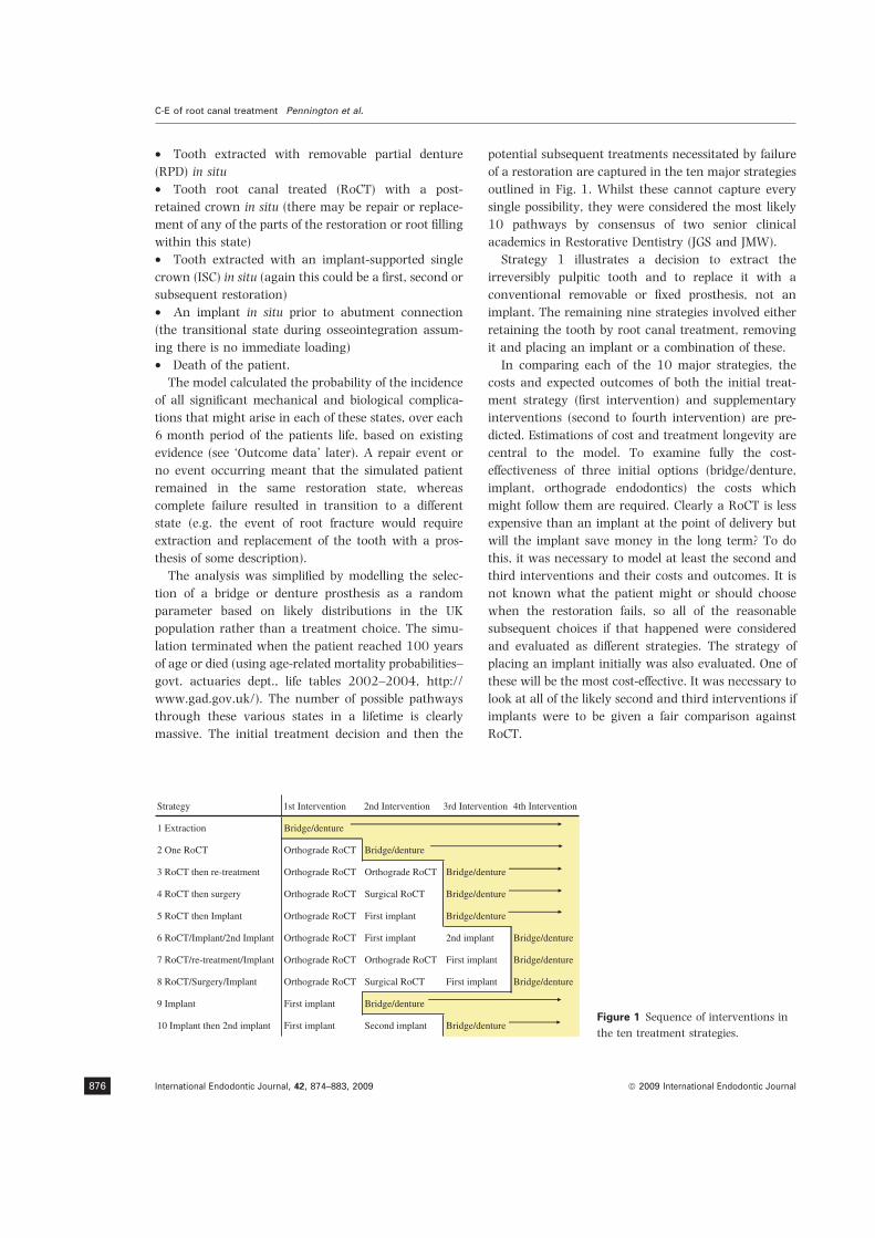
• Tooth extracted with removable partial denture
(RPD) in situ
• Tooth root canal treated (RoCT) with a post-
retained crown in situ (there may be repair or replace-
ment of any of the parts of the restoration or root filling
within this state)
• Tooth extracted with an implant-supported single
crown (ISC) in situ (again this could be a first, second or
subsequent restoration)
• An implant in situ prior to abutment connection
(the transitional state during osseointegration assum-
ing there is no immediate loading)
• Death of the patient.
The model calculated the probability of the incidence
of all significant mechanical and biological complica-
tions that might arise in each of these states, over each
6 month period of the patients life, based on existing
evidence (see ‘Outcome data’ later). A repair event or
no event occurring meant that the simulated patient
remained in the same restoration state, whereas
complete failure resulted in transition to a different
state (e.g. the event of root fracture would require
extraction and replacement of the tooth with a pros-
thesis of some description).
The analysis was simplified by modelling the selec-
tion of a bridge or denture prosthesis as a random
parameter based on likely distributions in the UK
population rather than a treatment choice. The simu-
lation terminated when the patient reached 100 years
of age or died (using age-related mortality probabilities–
govt. actuaries dept., life tables 2002–2004, http://
www.gad.gov.uk/). The number of possible pathways
through these various states in a lifetime is clearly
massive. The initial treatment decision and then the
potential subsequent treatments necessitated by failure
of a restoration are captured in the ten major strategies
outlined in Fig. 1. Whilst these cannot capture every
single possibility, they were considered the most likely
10 pathways by consensus of two senior clinical
academics in Restorative Dentistry (JGS and JMW).
Strategy 1 illustrates a decision to extract the
irreversibly pulpitic tooth and to replace it with a
conventional removable or fixed prosthesis, not an
implant. The remaining nine strategies involved either
retaining the tooth by root canal treatment, removing
it and placing an implant or a combination of these.
In comparing each of the 10 major strategies, the
costs and expected outcomes of both the initial treat-
ment strategy (first intervention) and supplementary
interventions (second to fourth intervention) are pre-
dicted. Estimations of cost and treatment longevity are
central to the model. To examine fully the cost-
effectiveness of three initial options (bridge/denture,
implant, orthograde endodontics) the costs which
might follow them are required. Clearly a RoCT is less
expensive than an implant at the point of delivery but
will the implant save money in the long term? To do
this, it was necessary to model at least the second and
third interventions and their costs and outcomes. It is
not known what the patient might or should choose
when the restoration fails, so all of the reasonable
subsequent choices if that happened were considered
and evaluated as different strategies. The strategy of
placing an implant initially was also evaluated. One of
these will be the most cost-effective. It was necessary to
look at all of the likely second and third interventions if
implants were to be given a fair comparison against
RoCT.
Strategy 1st Intervention 2nd Intervention 3rd Intervention 4th Intervention
1 Extraction Bridge/denture
2 One RoCT Orthograde RoCT Bridge/denture
3 RoCT then re-treatment Orthograde RoCT Orthograde RoCT Bridge/denture
4 RoCT then surgery Orthograde RoCT Surgical RoCT Bridge/denture
5 RoCT then Implant Orthograde RoCT First implant Bridge/denture
6 RoCT/Implant/2nd Implant Orthograde RoCT First implant 2nd implant Bridge/denture
7 RoCT/re-treatment/Implant Orthograde RoCT Orthograde RoCT First implant Bridge/denture
8 RoCT/Surgery/Implant Orthograde RoCT Surgical RoCT First implant Bridge/denture
9 Implant First implant Bridge/denture
10 Implant then 2nd implant First implant Second implant Bridge/dentureFigure 1 Sequence of interventions in
the ten treatment strategies.
C-E of root canal treatment Pennington et al.
International Endodontic Journal, 42, 874–883, 2009 ª 2009 International Endodontic Journal876
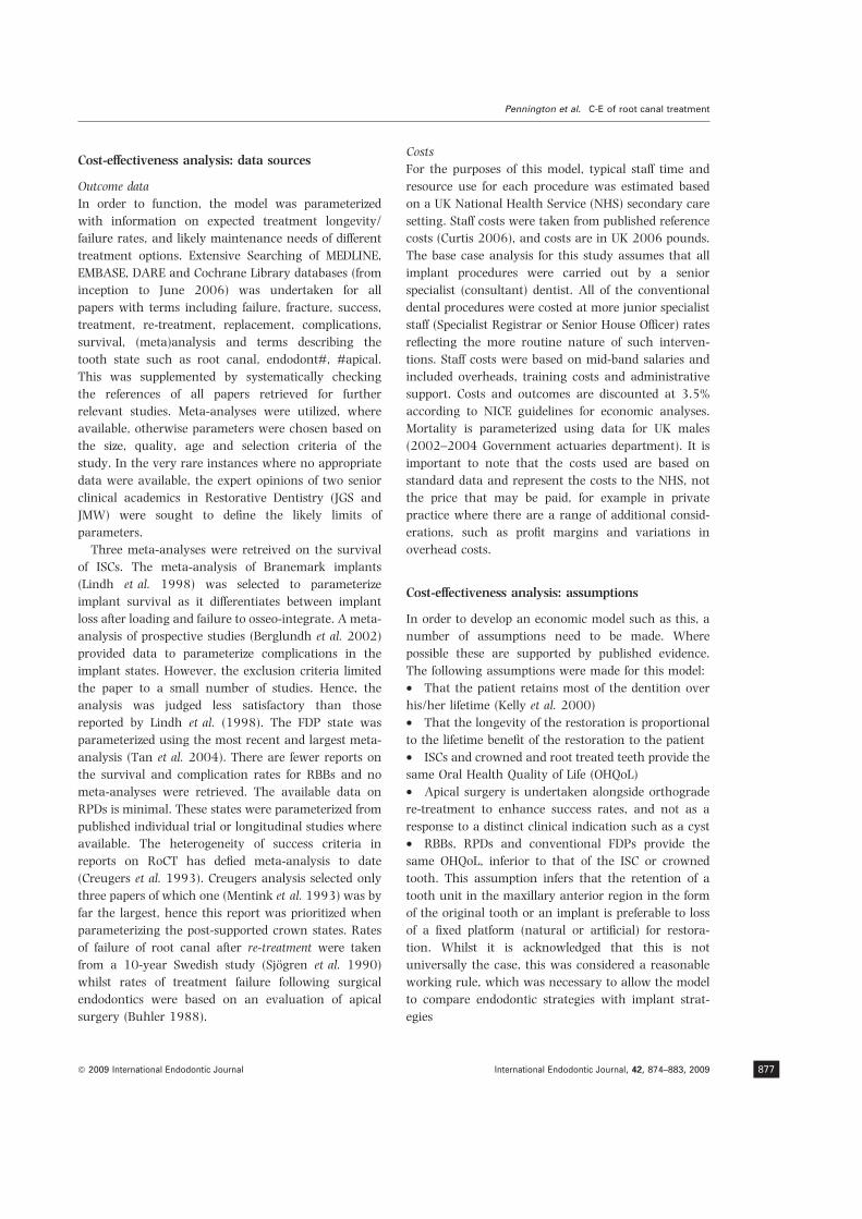
Cost-effectiveness analysis: data sources
Outcome data
In order to function, the model was parameterized
with information on expected treatment longevity/
failure rates, and likely maintenance needs of different
treatment options. Extensive Searching of MEDLINE,
EMBASE, DARE and Cochrane Library databases (from
inception to June 2006) was undertaken for all
papers with terms including failure, fracture, success,
treatment, re-treatment, replacement, complications,
survival, (meta)analysis and terms describing the
tooth state such as root canal, endodont#, #apical.
This was supplemented by systematically checking
the references of all papers retrieved for further
relevant studies. Meta-analyses were utilized, where
available, otherwise parameters were chosen based on
the size, quality, age and selection criteria of the
study. In the very rare instances where no appropriate
data were available, the expert opinions of two senior
clinical academics in Restorative Dentistry (JGS and
JMW) were sought to define the likely limits of
parameters.
Three meta-analyses were retreived on the survival
of ISCs. The meta-analysis of Branemark implants
(Lindh et al. 1998) was selected to parameterize
implant survival as it differentiates between implant
loss after loading and failure to osseo-integrate. A meta-
analysis of prospective studies (Berglundh et al. 2002)
provided data to parameterize complications in the
implant states. However, the exclusion criteria limited
the paper to a small number of studies. Hence, the
analysis was judged less satisfactory than those
reported by Lindh et al. (1998). The FDP state was
parameterized using the most recent and largest meta-
analysis (Tan et al. 2004). There are fewer reports on
the survival and complication rates for RBBs and no
meta-analyses were retrieved. The available data on
RPDs is minimal. These states were parameterized from
published individual trial or longitudinal studies where
available. The heterogeneity of success criteria in
reports on RoCT has defied meta-analysis to date
(Creugers et al. 1993). Creugers analysis selected only
three papers of which one (Mentink et al. 1993) was by
far the largest, hence this report was prioritized when
parameterizing the post-supported crown states. Rates
of failure of root canal after re-treatment were taken
from a 10-year Swedish study (Sjogren et al. 1990)
whilst rates of treatment failure following surgical
endodontics were based on an evaluation of apical
surgery (Buhler 1988).
Costs
For the purposes of this model, typical staff time and
resource use for each procedure was estimated based
on a UK National Health Service (NHS) secondary care
setting. Staff costs were taken from published reference
costs (Curtis 2006), and costs are in UK 2006 pounds.
The base case analysis for this study assumes that all
implant procedures were carried out by a senior
specialist (consultant) dentist. All of the conventional
dental procedures were costed at more junior specialist
staff (Specialist Registrar or Senior House Officer) rates
reflecting the more routine nature of such interven-
tions. Staff costs were based on mid-band salaries and
included overheads, training costs and administrative
support. Costs and outcomes are discounted at 3.5%
according to NICE guidelines for economic analyses.
Mortality is parameterized using data for UK males
(2002–2004 Government actuaries department). It is
important to note that the costs used are based on
standard data and represent the costs to the NHS, not
the price that may be paid, for example in private
practice where there are a range of additional consid-
erations, such as profit margins and variations in
overhead costs.
Cost-effectiveness analysis: assumptions
In order to develop an economic model such as this, a
number of assumptions need to be made. Where
possible these are supported by published evidence.
The following assumptions were made for this model:
• That the patient retains most of the dentition over
his/her lifetime (Kelly et al. 2000)
• That the longevity of the restoration is proportional
to the lifetime benefit of the restoration to the patient
• ISCs and crowned and root treated teeth provide the
same Oral Health Quality of Life (OHQoL)
• Apical surgery is undertaken alongside orthograde
re-treatment to enhance success rates, and not as a
response to a distinct clinical indication such as a cyst
• RBBs, RPDs and conventional FDPs provide the
same OHQoL, inferior to that of the ISC or crowned
tooth. This assumption infers that the retention of a
tooth unit in the maxillary anterior region in the form
of the original tooth or an implant is preferable to loss
of a fixed platform (natural or artificial) for restora-
tion. Whilst it is acknowledged that this is not
universally the case, this was considered a reasonable
working rule, which was necessary to allow the model
to compare endodontic strategies with implant strat-
egies
Pennington et al. C-E of root canal treatment
ª 2009 International Endodontic Journal International Endodontic Journal, 42, 874–883, 2009 877

• A constant hazard rate is assumed for mechanical
and biological complications following an intervention
• The same hazard rate applies to an event, such as
tooth fracture, in the post-supported crown states
regardless of whether a surgical or nonsurgical end-
odontic re-treatment had occurred. The exception to
this was the rate of root canal treatment failure for
which there was available data (see above)
• Probability of implant loss and peri-implantitis are
independent. These were modelled independently on
the basis of data reported in the literature (Berglundh
et al. 2002)
• Results are presented for UK males only on the
assumption that dental costs and benefits are indepen-
dent of gender. As life expectancy rather than gender
dictates costs, results for females would be similar to
those for a slightly younger cohort of males with the
same life expectancy
The literature consists predominantly of follow-up of
patients treated in dental hospitals, or in specialist
clinics in the case of implants. This may not accurately
reflect outcomes achieved in primary-care settings, but
robust data in these environments are generally lack-
ing. However, sensitivity analysis allowed the cost
variables related to hospital staff costs to be varied (see
below).
Cost effectiveness: ratio calculation
The outcome measure used in the cost-effectiveness
analysis is the total longevity of a fixed platform
supported crown, both root canal treated and post-
crowned natural tooth, and implant supported crowns.
After reviewing the costs and longevity for all ten
strategies and ranking them by cost, strategies that were
clearly less cost effective (those that were ‘dominated’ or
‘extendedly dominated’, see results) were removed and
the rest retained for the calculation of an incremental
cost-effectiveness ratio (ICER). This widely used index of
cost-effectiveness (Drummond et al. 2005) is the addi-
tional financial cost divided by the additional effective-
ness (in this case the prolonged longevity of the crown)
of that strategy over the next cheapest alternative.
Cost-effectiveness analysis: sensitivity analysis
The key parameters (such as costs and survival) are all
estimates and, by definition, likely to be imprecise. To
allow for this, plausible ranges for key parameters (such
as survival of restorations) were estimated by the
academic dental authors, allowing one-way sensitivity
analysis of the model to be undertaken for each of these
parameters. This re-running of the model with different
starting parameters illustrates the impact that the
inevitable inaccuracies might have on the overall
model.
The overall costs of each strategy are clearly a
product of the estimated dental procedure costs. Dental
costs are considerably lower in eastern European
countries but average wages and hence patient budgets
are also likely to be lower. However, varying the costs
of dental wages or implant components will influence
the relative cost-effectiveness of each treatment strat-
egy. The relative effect of decreasing component costs
or increasing dental salaries is likely to be similar –
implant costs will fall relative to alternative restorative
procedures and implant strategies will be more cost-
effective. We simulated three different potential cost
environments to illustrate the impact of higher and
lower wage costs and the impact of lower implant
component costs.
Results
Table 1 shows both the expected total lifetime costs and
the expected longevity of the root canal treated tooth
and/or implant supported crowns for a male aged 35,
55 and 75 years, without inflation. The values have
been ‘discounted’ to take account for change in
perceived value with time, using standard measures
recommended by NICE (http://www.nice.org.uk/
media/F13/6E/ITEM3FINALTAMethodsGuidePostCon-
sultationForBoardCover.pdf) and this partly accounts
for the relatively low monetary values in all strategies.
Crown longevity is the sum of the total lifetimes of root
canal treated tooth and/or implant supported crowns at
that site prior to failure and replacement with a bridge
or denture. It is assumed that if no endodontic or
implant treatment is provided there will still be a need
over the lifetime to fill the space, with a cost
consequence [statistically, unfilled anterior spaces are
very rare in the UK (Kelly et al. 2000)].
The model predicts superior survival of the ISC over a
conventional root canal treated tooth with a post-
crown based on published evidence. After 20 years
around 25% of root canal treated and re-treated teeth
are predicted to have been lost, whereas 10% of first
implants have failed, necessitating a further implant or
replacement with a bridge or denture. Despite improved
longevity, the implant based strategies still require
more interim interventions if a two stage procedure is
assumed.
C-E of root canal treatment Pennington et al.
International Endodontic Journal, 42, 874–883, 2009 ª 2009 International Endodontic Journal878

Figure 2 shows the cost accumulation (discounted)
for each strategy over 65 years for a male aged
35 years. The significantly greater initial outlay on
placing an implant is evident but slightly mitigated by
lower ongoing costs, illustrated by the rather shallow
curve. The ongoing costs of strategies five (RoCT/
Implant) and six (RoCT/Two implants) show the
steepest gradient, due to a combination of relatively
high failure rates of the first treatment (RoCT), and the
high cost of the second treatment (implant).
Cost-effectiveness analysis
The 10 strategies model both the initial intervention
and the possible subsequent interventions required to
maintain a tooth or prosthesis at that site for the
patient’s lifetime. To establish cost effectiveness these
are ranked in order of cost and their longevity
reviewed. When this was done, some strategies were
clearly less cost-effective because they have poorer
longevity but still cost more than others. They are said
to be ‘dominated’. Strategies five (RoCT/Implant), nine
(One Implant) and 10 (Two Implants) were dominated
for patients at all ages analysed (35, 45, 55, 65, 75,
85) and have been excluded.
The remaining strategies are each more effective
than less expensive alternatives, but some are signifi-
cantly more expensive than a comparator but only
marginally more effective. It would not make sense to
choose such a strategy if, by paying only a little more,
we could get a much bigger increase in effectiveness,
hence these strategies are excluded (they are said to be
‘extendedly dominated’). Both strategies involving a
surgical endodontic re-treatment (strategies four and
eight) fell in to this category at each age analysed.
Whilst surgical endodontic re-treatment has a higher
reported success rate than nonsurgical re-treatment in
some studies, this has generally followed endodontic
re-treatment. The overall increase in longevity, relative
to the increased cost, is small. Additional crown years
(longevity) can actually be achieved at a lower cost per
year with implants.
The results of the cost-effectiveness analysis are
shown in Table 2.1 Strategy 1 (No Treatment) is the
least effective and the cheapest, and so this is the
comparator for calculating the ICER for strategy two
0
200
400
600
800
1000
1200
1400
1600
1800
35 45 55 65 75 85 95Age
£
Implant/2nd implant ImplantRoCT/Implant/2nd implant RoCT/ImplantRoCT/Surg/Implant RoCT/re-treat/ImplantRoCT/Surg RoCT/re-treatOne RoCT Extraction
Figure 2 Cumulative costs of each strategy (male age
35 years).
Table 1 Base case results – cost and
total crown longevity for each strategy
Strategy
Male age 35
Cost
(£) Longevity
Male age 55
Cost
(£) Longevity
Male age 75
Cost
(£) Longevity
1 (Extraction) 731 0 649 0 540 0
2 (One RoCT) 805 15.81 717 12.62 597 7.1
3 (RoCT then re-treatment) 828 17.29 730 13.56 601 7.41
4 (RoCT then Surgery) 847 17.51 746 13.66 611 7.43
7 (RoCT/re-treatment/Implant) 1071 21.58 916 15.78 694 8
8 (RoCT/Surgery/Implant) 1079 21.59 924 15.78 701 8
5 (RoCT then Implant) 1113 21.47 967 15.73 736 7.99
6 (RoCT/Implant/2nd Implant) 1140 21.85 983 15.88 741 8.02
9 (Implant) 1623 20.12 1570 14.96 1487 7.74
10 (Implant then 2nd Implant) 1717 21.73 1642 15.83 1527 8.01
1The costs generated by the model are the expected future
costs discounted to the present and not the actual costs faced
by a patient if he/she was to receive each of the interventions
in the strategy. We would expect many patients to die with an
intact root treated tooth, only a proportion will go onto to
receive subsequent interventions and the model presents the
‘average’ costs given the likelihood of failure of restorations
undertaken.
Pennington et al. C-E of root canal treatment
ª 2009 International Endodontic Journal International Endodontic Journal, 42, 874–883, 2009 879
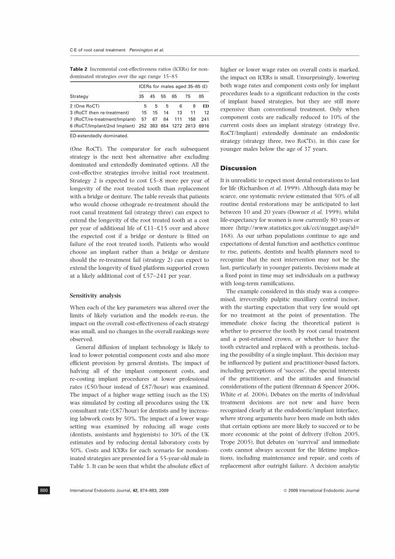
(One RoCT). The comparator for each subsequent
strategy is the next best alternative after excluding
dominated and extendedly dominated options. All the
cost-effective strategies involve initial root treatment.
Strategy 2 is expected to cost £5–8 more per year of
longevity of the root treated tooth than replacement
with a bridge or denture. The table reveals that patients
who would choose othograde re-treatment should the
root canal treatment fail (strategy three) can expect to
extend the longevity of the root treated tooth at a cost
per year of additional life of £11–£15 over and above
the expected cost if a bridge or denture is fitted on
failure of the root treated tooth. Patients who would
choose an implant rather than a bridge or denture
should the re-treatment fail (strategy 2) can expect to
extend the longevity of fixed platform supported crown
at a likely additional cost of £57–241 per year.
Sensitivity analysis
When each of the key parameters was altered over the
limits of likely variation and the models re-run, the
impact on the overall cost-effectiveness of each strategy
was small, and no changes in the overall rankings were
observed.
General diffusion of implant technology is likely to
lead to lower potential component costs and also more
efficient provision by general dentists. The impact of
halving all of the implant component costs, and
re-costing implant procedures at lower professional
rates (£50/hour instead of £87/hour) was examined.
The impact of a higher wage setting (such as the US)
was simulated by costing all procedures using the UK
consultant rate (£87/hour) for dentists and by increas-
ing labwork costs by 50%. The impact of a lower wage
setting was examined by reducing all wage costs
(dentists, assistants and hygienists) to 30% of the UK
estimates and by reducing dental laboratory costs by
50%. Costs and ICERs for each scenario for nondom-
inated strategies are presented for a 55-year-old male in
Table 3. It can be seen that whilst the absolute effect of
higher or lower wage rates on overall costs is marked,
the impact on ICERs is small. Unsurprisingly, lowering
both wage rates and component costs only for implant
procedures leads to a significant reduction in the costs
of implant based strategies, but they are still more
expensive than conventional treatment. Only when
component costs are radically reduced to 10% of the
current costs does an implant strategy (strategy five,
RoCT/Implant) extendedly dominate an endodontic
strategy (strategy three, two RoCTs), in this case for
younger males below the age of 37 years.
Discussion
It is unrealistic to expect most dental restorations to last
for life (Richardson et al. 1999). Although data may be
scarce, one systematic review estimated that 50% of all
routine dental restorations may be anticipated to last
between 10 and 20 years (Downer et al. 1999), whilst
life-expectancy for women is now currently 80 years or
more (http://www.statistics.gov.uk/cci/nugget.asp?id=
168). As our urban populations continue to age and
expectations of dental function and aesthetics continue
to rise, patients, dentists and health planners need to
recognize that the next intervention may not be the
last, particularly in younger patients. Decisions made at
a fixed point in time may set individuals on a pathway
with long-term ramifications.
The example considered in this study was a compro-
mised, irreversibly pulpitic maxillary central incisor,
with the starting expectation that very few would opt
for no treatment at the point of presentation. The
immediate choice facing the theoretical patient is
whether to preserve the tooth by root canal treatment
and a post-retained crown, or whether to have the
tooth extracted and replaced with a prosthesis, includ-
ing the possibility of a single implant. This decision may
be influenced by patient and practitioner-based factors,
including perceptions of ‘success’, the special interests
of the practitioner, and the attitudes and financial
considerations of the patient (Brennan & Spencer 2006,
White et al. 2006). Debates on the merits of individual
treatment decisions are not new and have been
recognized clearly at the endodontic/implant interface,
where strong arguments have been made on both sides
that certain options are more likely to succeed or to be
more economic at the point of delivery (Felton 2005,
Trope 2005). But debates on ‘survival’ and immediate
costs cannot always account for the lifetime implica-
tions, including maintenance and repair, and costs of
replacement after outright failure. A decision analytic
Table 2 Incremental cost-effectiveness ratios (ICERs) for non-
dominated strategies over the age range 35–85
Strategy
ICERs for males aged 35–85 (£)
35 45 55 65 75 85
2 (One RoCT) 5 5 5 6 8 ED
3 (RoCT then re-treatment) 15 15 14 13 11 12
7 (RoCT/re-treatment/Implant) 57 67 84 111 158 241
6 (RoCT/Implant/2nd Implant) 252 383 654 1272 2813 6916
ED-extendedly dominated.
C-E of root canal treatment Pennington et al.
International Endodontic Journal, 42, 874–883, 2009 ª 2009 International Endodontic Journal880
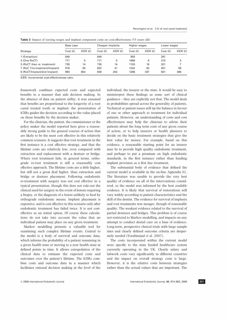
framework combines expected costs and expected
benefits in a manner that aids decision making. In
the absence of data on patient utility, it was assumed
that benefits are proportional to the longevity of a root
canal treated tooth or implant; the presentation of
ICERs guides the decision according to the value placed
on those benefits by the decision maker.
For the clinician, the patient, the commissioner or the
policy maker the model reported here gives a reason-
ably strong guide to the general courses of action that
are likely to be the most cost effective in this relatively
common scenario. It suggests that root treatment in the
first instance is a cost effective strategy, and that the
lifetime costs are relatively low, even compared with
extraction and replacement with a denture or bridge.
Where root treatment fails, in general terms, ortho-
grade re-root treatment is still a reasonably cost
effective approach. The lifetime costs are a little higher,
but still not a great deal higher, than extraction and
bridge or denture placement. Following endodontic
re-treatment with surgery was not cost effective in a
typical presentation, though this does not rule-out the
clinical need for surgery in the event of lesions requiring
a biopsy, or the diagnosis of a lesion unlikely to heal by
orthograde endodontic means. Implant placement is
expensive, and is cost effective in this scenario only after
endodontic treatment has failed twice. It is not cost-
effective as an initial option. Of course these calcula-
tions do not take into account the value that an
individual patient may place on any given treatment.
Markov modelling presents a valuable tool for
examining such complex lifetime events. Central to
the model is a body of survival and outcome data,
which informs the probability of a patient remaining in
a given health state or moving to a new health state at
defined points in time. It allows extrapolation of the
clinical data to estimate the expected costs and
outcomes over the patient’s lifetime. The ICERs com-
bine costs and outcome data in a manner which
facilitates rational decision making at the level of the
individual, the insurer or the state. It would be easy to
misinterpret these findings as some sort of clinical
guidance – they are explicitly not that. The model deals
in probabilities spread across the generality of patients.
Technical or patient issues will tip the balance in favour
of one or other approach to treatment for individual
patients. However, an understanding of costs and cost
effectiveness may help the clinician to advise their
patients about the long term costs of any given course
of action, or to help insurers or health planners to
decide on the basic treatment strategies that give the
best value for money. For example, based on this
evidence, a reasonable starting point for an insurer
may be to provide high quality endodontic treatment,
and perhaps to put a premium on high endodontic
standards, in the first instance rather than funding
implant provision as a first line treatment.
The substantial body of evidence that defined the
current model is available in the on-line Appendix S1.
The literature was unable to provide the very best
quality of evidence on all of the interventions consid-
ered, so the model was informed by the best available
evidence. It is likely that survival of restorations will
vary widely according to patient characteristics and the
skill of the dentist. The evidence for survival of implants
and root treatments was meagre, though of reasonable
quality. The weakest evidence related to the survival of
partial dentures and bridges. This problem is of course
not restricted to Markov modelling, and impacts on any
attempt to conduct dental care on a base of evidence.
Long-term, prospective clinical trials with large sample
sizes and clearly defined outcome criteria are desper-
ately needed (Torabinejad et al. 2007).
The costs incorporated within the current model
were specific to the state funded healthcare system
currently operating in the UK. Clearly salary and
labwork costs vary significantly in different countries
and the impact on overall strategy costs is large.
However, it is the relative costs between strategies
rather than the actual values that are important. The
Table 3 Impact of varying wages and implant component costs on cost-effectiveness (55 years old)
Strategy
Base case Cheaper implants Higher wages Lower wages
Cost (£) ICER (£) Cost (£) ICER (£) Cost (£) ICER (£) Cost (£) ICER (£)
1 (Extraction) 649 649 993 281
2 (One RoCT) 717 5 717 5 1088 8 315 3
3 (RoCT then re -treatment) 730 14 730 14 1103 16 321 7
7 (RoC T/re-treatment/Implant) 916 84 822 41 1242 63 451 59
6 (RoCT/Implant/2nd Implant) 983 654 848 254 1286 437 501 486
ICER, incremental cost-effectiveness ratio.
Pennington et al. C-E of root canal treatment
ª 2009 International Endodontic Journal International Endodontic Journal, 42, 874–883, 2009 881

relative impact of changing wage costs is surprisingly
small. ICERs are changed, but not by an order of
magnitude, and overall ranking of strategies remains
the same. Hence recommendations based on the
calculated ICERs are less susceptible to care costs in
different settings. The sensitivity analysis, which dem-
onstrated the stability of the strategy rankings to
changes in event probabilities and costs, suggests the
findings are robust.
Conclusions
Root canal treatment is an appropriate and cost-
effective intervention to extend the life of a maxillary
incisor tooth with a diseased pulp. Orthograde
re-treatment is also cost-effective, but unless clinically
indicated the benefits of additional apical surgery do
not justify the additional cost. Increased longevity of
the crown can be achieved at a lower cost per year with
an implant. At current costs the role of implants is
limited to a third line intervention if re-treatment fails.
Acknowledgements
The authors are grateful for the advice of Pelham
Barton on the appropriate analysis of sequential
treatment decisions, and the critical review and com-
ments from Rob Anderson. This work was undertaken
by Mark Pennington at Newcastle University without
external financial support.
References
Balevi B (2008) The management of incipient or suspicious
occlusal caries: a decision tree analysis. Community Dentistry
& Oral Epidemiology 36, 392–400.
Berglundh T, Persson L, Klinge B (2002) A systematic review
of the incidence of biological and technical complications in
implant dentistry reported in prospective longitudinal stud-
ies of at least 5 years. Journal of Clinical Periodontology
29(Suppl. 3), 197–212.
Bragger U, Krenander P, Lang NP (2005) Economic aspects of
single-tooth replacement. Clinical Oral Implants Research 16,
335–41.
Brennan DS, Spencer AJ (2006) Dentist preferences for
patients: dimensions and associations with provider, prac-
tice, and service characteristics. International Journal of
Behavioral Medicine 13, 69–78.
Buhler H (1988) Evaluation of root-resected teeth. Results
after 10 years. Journal of Periodontology 59, 805–10.
Calnan M, Payne S, Kemple T, Rossdale M, Ingram J (2007) A
qualitative study exploring variations in GPs’ out-of-hours
referrals to hospital. British Journal of General Practice 57,
706–13.
Chan DC, Heidenreich PA, Weinstein MC, Fonarow GC (2008)
Heart failure disease management programs: a cost-
effectiveness analysis. American Heart Journal 155, 332–8.
Creugers NH, Mentink AG, Kayser AF (1993) An analysis of
durability data on post and core restorations. Journal of
Dentistry 21, 281–4.
Curtis LNA. (2006) Unit Costs of Health and Social
Care. [WWW document]. http://www.pssru.ac.uk/ URL|
[accessed on 26 September 2008].
Domejean-Orliaguet S, Tubert-Jeannin S, Riordan PJ, Espelid I,
Tveit AB (2004) French dentists’ restorative treatment
decisions. Oral Health & Preventive Dentistry 2, 125–31.
Downer MC, Azli NA, Bedi R, Moles DR, Setchell DJ (1999)
How long do routine dental restorations last? A systematic
review. British Dental Journal 187, 432–9.
Drummond M, Sculpher M, Torrance G, O’Brien B, Stoddart G
(2005) Methods for the Economic Evaluation of Health Care
Programmes, 3rd edn. Oxford: Oxford University Press.
Edwards MJ, Brickley MR, Goodey RD, Shepherd JP (1999)
The cost, effectiveness and cost effectiveness of removal and
retention of asymptomatic, disease free third molars. British
Dental Journal 187, 380–4.
Felton DA (2005) Implant or root canal therapy: a prostho-
dontist’s view. Journal of Esthetic & Restorative Dentistry:
Official Publication of the American Academy of Esthetic
Dentistry 17, 197–9.
Kaba R, Sooriakumaran P (2007) The evolution of the doctor-
patient relationship. International Journal Of Surgery 5, 57–
65.
Kelly M, Steele J, Nuttall N et al. (2000) Adult Dental Health
Survey: Oral Health in the United Kingdom in 1998. London:
TSO.
Lanning SK, Pelok SD, Williams BC et al. (2005) Variation
in periodontal diagnosis and treatment planning among
clinical instructors. Journal of Dental Education 69, 325–
37.
Lindh T, Gunne J, Tillberg A, Molin M (1998) A meta-analysis
of implants in partial edentulism. Clinical Oral Implants
Research 9, 80–90.
McColl E, Smith M, Whitworth J, Seccombe G, Steele J (1999)
Barriers to improving endodontic care: the views of NHS
practitioners. British Dental Journal 186, 564–8.
Mentink AG, Meeuwissen R, Kayser AF, Mulder J (1993)
Survival rate and failure characteristics of the all metal post
and core restoration. Journal of Oral Rehabilitation 20, 455–
61.
Mileman PA, van den Hout WB (2003) Preferences for oral
health states: effect on prescribing periapical radiographs.
Dentomaxillofacial Radiology 32, 401–7.
Raiffa H (1968) Decision Analysis: introductory lecture on choices
under uncertainty. Reading, MA: Addison-Wesley.
Richardson R, Treasure E, Sheldon T (1999) On the evidence.
Dental restoration. Health Service Journal 109, 28–9.
C-E of root canal treatment Pennington et al.
International Endodontic Journal, 42, 874–883, 2009 ª 2009 International Endodontic Journal882

van der Sanden WJM, Mettes DG, Plasschaert AJM, Grol
RPTM, Mulder J, Verdonschot EH (2005) Effectiveness of
clinical practice guideline implementation on lower third
molar management in improving clinical decision-making:
a randomized controlled trial. European Journal of Oral
Sciences 113, 349–54.
Sjogren U, Hagglund B, Sundqvist G, Wing K (1990) Factors
affecting the long-term results of endodontic treatment.
Journal of Endodontics 16, 498–504.
Sonnenberg FA, Beck JR (1993) Markov models in medical
decision making: a practical guide. Medical Decision Making
13, 322–38.
Svatek RS, Lee JJ, Roehrborn CG, Lippman SM, Lotan Y (2008)
Cost-effectiveness of prostate cancer chemoprevention: a
quality of life-years analysis. Cancer 112, 1058–65.
Takao H, Nojo T, Ohtomo K (2008) Treatment of ruptured
intracranial aneurysms: a decision analysis. British Journal
of Radiology 81, 299–303.
Tan K, Pjetursson BE, Lang NP, Chan ES (2004) A systematic
review of the survival and complication rates of fixed partial
dentures (FPDs) after an observation period of at least
5 years. Clinical Oral Implants Research 15, 654–66.
Tickle M, Threlfall AG, Pilkington L, Milsom KM, Duggal MS,
Blinkhorn AS (2007) Approaches taken to the treatment of
young children with carious primary teeth: a national cross-
sectional survey of general dental practitioners and paediat-
ric specialists in England. British Dental Journal 203, 102–3.
Torabinejad M, Anderson P, Bader J et al. (2007) Outcomes of
root canal treatment and restoration, implant-supported
single crowns, fixed partial dentures, and extraction without
replacement: a systematic review. Journal of Prosthetic
Dentistry 98, 285–311.
Trope M (2005) Implant or root canal therapy: an endodon-
tist’s view. Journal of Esthetic & Restorative Dentistry: Official
Publication of the American Academy of Esthetic Dentistry 17,
139–40.
White SN, Miklus VG, Potter KS, Cho J, Ngan AYW (2006)
Endodontics and implants, a catalog of therapeutic con-
trasts. The Journal of Evidencebased Dental Practice 6, 101–9.
Supporting Information
Additional Supporting Information may be found in the
online version of this article:
Appendix S1. A detailed description of the model
including all of the data sources used to parameterise
it.
Please note: Wiley-Blackwell are not responsible for
the content or functionality of any supporting materials
supplied by the authors. Any queries (other than
missing material) should be directed to the correspond-
ing author for the article.
Pennington et al. C-E of root canal treatment
ª 2009 International Endodontic Journal International Endodontic Journal, 42, 874–883, 2009 883

Long-term sealing ability of Resilon apicalroot-end fillings
M. A. A. De Bruyne & R. J. G. De MoorDepartment of Operative Dentistry and Endodontology, Dental School, Ghent University, Ghent University Hospital, Gent, Belgium
Abstract
De Bruyne MAA, De Moor RJG. Long-term sealing ability
of Resilon apical root-end fillings. International Endodontic
Journal, 42, 884–892, 2009.
Aim To evaluate ex vivo the long-term sealing ability
of the SE Resilon Epiphany system as an apical root-end
filling material.
Methodology A total of 60 standardized horizontal
bovine root sections were divided into three groups filled
with either gutta-percha with AH 26, tooth-coloured
mineral trioxide aggregate (MTA) or Resilon pellets with
Epiphany SE, and submitted to capillary flow porometry
at 48 h, 1 and 6 months to assess the minimum, mean
flow and maximum pore diameters. Results of the
different materials and results bymaterial and time were
analysed statistically using nonparametric tests; the
level of significance was set at 0.05.
Results Resilon had smaller pore diameters than
gutta-percha and MTA at 48 h and smaller mean flow
and maximum pore diameters than gutta-percha and
MTA at 1 month. At 6 months Resilon had larger
minimum pore diameters than gutta-percha. Although
not always statistically significant, the minimum,
mean flow and maximum pore diameters of gutta-
percha and MTA diminished with time. This was not
the case for Resilon, where the same parameters
increased.
Conclusions All materials leaked at all times. Resi-
lon performed better than gutta-percha and MTA in the
short-term, but the seal of MTA and gutta-percha
improved over time whereas the seal of Resilon
deteriorated. It is critical to evaluate the performance
of materials in the long-term contrary to most studies
which are short-term.
Keywords: capillary flow porometry, Epiphany,
leakage, Resilon, root-end filling, seal.
Received 14 October 2008; accepted 17 March 2009
Introduction
When orthograde root canal treatment is associated
with post-treatment disease, surgical endodontics may
be indicated. The procedure involves surgical debride-
ment of pathological periradicular tissue, apical root-
end resection, root-end cavity preparation and the
placement of a root-end filling in an attempt to seal the
root canal (Gutmann & Harrison 1994). The root-end
filling should ideally produce a fluid-tight seal that
prevents residual irritants and oral contaminants from
exiting the root canal system and entering the perira-
dicular tissues (Arens et al. 1998).
An ideal root-end filling material would adhere and
adapt to the walls of the root-end preparation, prevent
leakage of micro-organisms and their toxins into the
periradicular tissues, be biocompatible, be insoluble in
tissue fluids and dimensionally stable and remain
unaffected by the presence of moisture (Arens et al.
1998). It is generally accepted that the most fluid-tight
apical seal possible is required for successful periapical
healing (Hirsch et al. 1979). If the seal is not fluid-tight,
microleakage may occur. Leakage of various root-end
filling materials has been investigated widely, mainly
using dye penetration methods. However, there are
certain disadvantages in using the linear measurement
Correspondence: Dr M. A. A. De Bruyne, Department of
Operative Dentistry and Endodontology, Dental School, Ghent
University, Ghent University Hospital, De Pintelaan 185 P8,
9000 Gent, Belgium (Tel.: +32/9/332 58 35; fax: +32/9/332
38 51; e-mail: [email protected]).
doi:10.1111/j.1365-2591.2009.01583.x
International Endodontic Journal, 42, 884–892, 2009 ª 2009 International Endodontic Journal884
of dye penetration, including the destruction of the
specimen, which makes further evaluation of samples
impossible, and the lack of reproducible and compara-
ble results (Schuurs et al. 1993, Wu & Wesselink
1993).
The reported pattern of leakage in endodontics differs
according to the various techniques adopted (Wu et al.
2003). The fluid transport method was first reported by
Greenhill & Pashley (1981) and adapted by Wu et al.
(1993). This method investigates through-and-through
voids and the result when using this technique
indicates the diameter of the void. The dye penetration
method investigates through-and-through as well as
cul-de-sac voids and the result when using this
technique indicates the length of the void rather than
the diameter (Wu et al. 2003).
Capillary flow porometry which was first introduced
in dentistry in 2005 (De Bruyne et al. 2005) is also
used to evaluate through-and-through voids. This
technique is used in membrane and filter media testing
to measure through pores (Jena & Gupta 2002), as does
the fluid transport method. In contrast to the fluid
transport method, which gives an indication on the
diameter of the void, CFP provides exact information on
the diameter of the minimum, mean flow and maxi-
mum pore diameter at its most constricted part. The
method has been approved by the American Society of
Testing and Materials (1999) and was adapted suc-
cessfully in collaboration with VITO (Flemish Institute
for Technological Research, Mol, Belgium) to evaluate
through pores in filled root canals or root sections
(De Bruyne et al. 2005). The method also provides
information on pore distribution.
A variety of substances have been proposed as root-
end filling materials including amalgam, gutta-percha,
zinc oxide–eugenol cements, dentine bonding agents,
glass–ionomer cements, mineral trioxide aggregate
(MTA) and other restorative materials (Gutmann &
Harrison 1994). MTA shows excellent biocompatibility
(De Bruyne & De Moor 2004) and, in spite of the limited
clinical research, is considered by many clinicians as a
standard during apical surgery (Nicholson et al. 1991,
Asrari & Lobner 2003, Pistorius et al. 2003, Sousa
et al. 2004). After the introduction of grey MTA a
tooth-coloured or white MTA was introduced (Matt
et al. 2004, Tselnik et al. 2004). Gutta-percha has been
used frequently as a root-end filling material in the past
and often the filling material is exposed apically when
no root-end filling is placed. The Epiphany endodontic
obturation system (Pentron, Wallingford, CT, USA)
consists of Resilon obturation material available in
points and pellets, and a dual-cure, hydrophilic resin
sealer. The Resilon points or pellets can be processed in
the same way as gutta-percha. Recently, a self-etch (SE)
version of this sealer was introduced. Resilon material
is a formulation of polymers of polyester with fillers and
radiopacifers in a soft resin matrix. The pellets are used
with a delivery system (Obtura-Spartan, Fenton, MO,
USA). The manufacturer claims that after curing the
combination of obturation material and sealer will
create a monoblock in the canal that effectively resists
leakage.
After periradicular surgery, the surface of the root-end
filling is exposed to the periapical environment. Because
of this exposure, decomposition of the material may
occur and the seal of the filling may degrade. In order to
obtain information on the performance of root-end
filling materials on the long-term, the seal of root-end
filling materials should be tested at different intervals
after filling (Wu et al. 1998, De Bruyne et al. 2006).
The purpose of this study was to evaluate the sealing
ability of the SE Resilon-Epiphany system as a root-end
filling material and to compare it with warm gutta-
percha and white MTA in standard bovine root sections
at 48 h and after 1 and 6 months.
Materials and methods
Preparation and filling of root sections
Roots of freshly extracted bovine incisors with an
external diameter of approximately 7 mm were selected
and prepared into standardized sections 3 mm high.
The central pulp lumen was drilled to 2.5 mm in
diameter. For this purpose, the sections which were
verified to have a natural internal diameter smaller
than 2.5 mm were fixed in a clamp. A bur of 2.5 mm
in diameter which was secured in a fixed position was
passed once through the lumen.
Sixty of these sections were divided into three
different groups and each group was filled according
to the following scheme:
Group 1: warm gutta-percha (Obtura II, Obtura-
Spartan) and AH 26 (Dentsply De Trey, Konstanz,
Germany) (gutta-percha).
Group 2: Pro-Root MTA Tooth-Colored Formula
(Dentsply Tulsa, Tulsa, OK, USA) (MTA).
Group 3: Resilon pellets (Pentron) (Obtura II delivery
system; Obtura-Spartan) and Epiphany SE (Pentron)
(Resilon).
The root sections were rinsed with physiological
saline solution, dried with paper points and air spray
De Bruyne & De Moor Resilon root-end fillings
ª 2009 International Endodontic Journal International Endodontic Journal, 42, 884–892, 2009 885

and placed on a glass plate on top of a strip of polyester.
All materials were mixed and handled according to the
manufacturer’s instructions and the root sections were
filled. The filling materials were condensed with a
plugger (RCPS 12P; Hu Friedy, Chicago, IL, USA) and
excess material was removed. The root sections were
kept for 24 h at a temperature of 37 �C and 95–100%
relative humidity and then immersed in demineralized
water for 24 h before measurement. After the first
capillary flow measurement at 48 h the root sections
were removed from the capillary flow porometer and
stored in demineralized water at a temperature of
37 �C. They remained under these conditions except
during the follow-up measurements that were under-
taken at 1 and 6 months.
Measurement of capillary flow
Capillary flow porometry (CFP-1200-A; PMI, Ithaca,
NY, USA) provides fully automated through pore anal-
ysis. A wetting liquid (Galwick: 15.9 Dynes cm)1, PMI)
was used to fill the pores of the sample. Because the
wetting liquid’s liquid/solid surface free energy is less
than the solid/gas surface free energy, filling of the pores
is spontaneous, but removal of the liquid from the pores is
not. In order to remove thewetting liquid from pores and
permit gas flow, pressure must be applied to the sample.
The fully wetted sections were fixed in the sample
chamber afterwhich the sample chamberwas sealed.Air
was then allowed to flow into the chamber behind the
sample.When the pressure reaches a point, it overcomes
the capillary action of the fluid within the largest pore
(maximumpore), and the sample’s bubble point pressure
is identified. After determination of the bubble point
pressure, the pressure is increased and the flow is
measured until all pores are empty, and the sample is
considered dry. At this time the smallest or minimum
pore has been identified. Themean flow pore is described
as follows: half of the flow through a dry sample is
through pores having a diameter greater than the mean
flow pore diameter. The other half of the flow is through
pores having a diameter smaller than themean flow pore
diameter. Pressure in CFP ranges from 0 to 200 psi or
1.4 MPa and the pore size range that can be measured
lies between 0.035 and 500 lm. The flow meters detect
the presence of pores by sensing the increase in flow rate
due to emptying of pores. Differential pressures and flow
rates through wet and dry samples are measured.
Application of differential pressure on excess liquid on
the sample causes liquid displacement. Measurement of
the volume of displaced liquid allows computation of
liquid permeability. The pore diameter (D) is derived from
the following equation: D = 4 c cos h/p (c = surface
tension of the wetting liquid, h = contact angle of the
wetting liquid, p = differential pressure required to
displace the wetting liquid from the pore) (Jena & Gupta
2003). All measurements were performed at VITO
(Vlaamse Instelling voor Technologisch Onderzoek or
Flemish Institute for Technological Research).
Statistical analysis
Results were analysed statistically using nonparametric
tests. Comparisons were made between the leakage
results of the different materials at 48 h, 1 and
6 months using Kruskal–Wallis tests; two by two
analyses were performed by Mann–Whitney U-tests
with Bonferroni correction.
Comparisons between the leakage results of each
material at the specified time intervals were completed
using Friedman tests and two by two comparisons were
carried out by Wilcoxon Signed Ranks tests with
Bonferroni correction. The level of significance was
set at 0.05.
Results
Measurements were obtained for each sample at each
point in time, confirming the presence of through pores
regardless of which root-end filling material was being
tested. Exact values for minimum, mean flow and
maximum pore diameters of each sample were
obtained.
The results of the study are summarized in Tables 1–
3. For reasons of completeness the range and median of
minimum, mean flow and maximum pore diameters of
gutta-percha and MTA as reported in De Bruyne et al.
(2006) are repeated in Tables 1–3.
Leakage results at 48 h, 1 and 6 months
From the Kruskal–Wallis tests and the Mann–Whitney
U-tests with Bonferroni correction the following results
were obtained. At 48 h significant differences between
the minimum (P < 0.001), mean flow (P < 0.001) and
maximum (P < 0.001) pore diameters could be dem-
onstrated.
No significant differences between gutta-percha and
MTA could be demonstrated but there were significant
differences between gutta-percha and Resilon and
between MTA and Resilon for minimum, mean flow
and maximum pore diameters. At 48 h Resilon showed
Resilon root-end fillings De Bruyne & De Moor
International Endodontic Journal, 42, 884–892, 2009 ª 2009 International Endodontic Journal886

smaller pore diameters than gutta-percha and MTA.
The range and median of minimum, mean flow and
maximum pore diameters at 48 h are shown in
Table 1.
At 1 month there was no significant difference
between the minimum pore diameters of the different
materials, but significant differences between the mean
flow (P < 0.001) and maximum (P < 0.001) pore
diameters could be demonstrated. Concerning the
mean flow and maximum pore diameters, no signifi-
cant differences between gutta-percha and MTA could
be demonstrated, but there were significant differences
between gutta-percha and Resilon and between MTA
and Resilon. At 1 month Resilon showed smaller mean
flow and maximum pore diameters than gutta-percha
and MTA. The range and median of minimum, mean
flow and maximum pore diameters at 1 month are
shown in Table 2.
At 6 months a significant difference between the
minimum pore diameters could be demonstrated
(P < 0.05), but there were no significant differences
between the mean flow and maximum pore diameters
of the different materials. Concerning the minimum
pore diameters, there was a significant difference
between gutta-percha and Resilon. No significant
differences between gutta-percha and MTA and
between MTA and Resilon could be demonstrated.
At 6 months Resilon showed larger minimum pore
diameters than gutta-percha. The range and median of
minimum, mean flow and maximum pore diameters at
6 months are shown in Table 3.
Leakage results by material
From the Friedman tests the following results were
obtained. Concerning the minimum pore diameters
there were significant differences between the different
points in time for gutta-percha and MTA, but not for
Resilon. Results of the two by two comparisons are
summarized in Table 4. Statistically significant
Table 1 Range and median of minimum, mean flow and maximum pore diameters by root-end filling material at 48 h (lm)
Group Filling material
Minimum pore diameter
(lm)
Mean flow pore diameter
(lm)
Maximum pore diameter
(lm)
Range Median Range Median Range Median
1 GP + AH 26 0.075–0.355 0.1995 0.141–0.395 0.2630 0.177–1.714 0.4375
2 MTA 0.070–0.258 0.2210 0.183–0.925 0.2760 0.193–1.304 0.4440
3 Resilon 0.082–0.201 0.1165 0.100–0.272 0.1465 0.127–0.433 0.2140
MTA, mineral trioxide aggregate.
Table 2 Range and median of minimum, mean flow and maximum pore diameters by root-end filling material at 1 month (lm)
Group Filling material
Minimum pore diameter
(lm)
Mean flow pore diameter
(lm)
Maximum pore diameter
(lm)
Range Median Range Median Range Median
1 GP + AH 26 0.070–0.362 0.0875 0.106–0.455 0.2730 0.128–0.896 0.4410
2 MTA 0.070–0.330 0.2010 0.152–0.393 0.2880 0.162–0.854 0.4370
3 Resilon 0.069–0.198 0.1175 0.075–0.350 0.1525 0.088–0.432 0.2265
MTA, mineral trioxide aggregate.
Table 3 Range and median of minimum, mean flow and maximum pore diameters by root-end filling material at 6 months (lm)
Group Filling material
Minimum pore diameter
(lm)
Mean flow pore diameter
(lm)
Maximum pore diameter
(lm)
Range Median Range Median Range Median
1 GP + AH 26 0.069–0.199 0.1060 0.077–0.302 0.1315 0.104–0.418 0.2200
2 MTA 0.069–0.216 0.1055 0.084–0.346 0.1490 0.111–0.818 0.2455
3 Resilon 0.083–0.240 0.1335 0.095–0.340 0.1685 0.106–0.402 0.2380
MTA, mineral trioxide aggregate.
De Bruyne & De Moor Resilon root-end fillings
ª 2009 International Endodontic Journal International Endodontic Journal, 42, 884–892, 2009 887

decreases in size were found between 48 h and
6 months for gutta-percha and MTA and between 1
and 6 months for MTA.
Concerning the mean flow pore diameters there were
significant differences between the different points in
time for gutta-percha and MTA but not for Resilon.
Results of the two by two comparisons are summarized
in Table 4. Statistically significant decreases in size
were found for gutta-percha and MTA between 48 h
and 6 months and between 1 and 6 months.
Concerning the maximum pore diameters there were
significant differences between the different points in
time for gutta-percha but not for MTA and Resilon.
Results of the two by two comparisons are summarized
in Table 4. Statistically significant decreases in size
were found for gutta-percha between 48 h and
6 months and between 1 and 6 months.
Discussion
Capillary flow porometry generates highly reproducible
and accurate data (Gupta & Jena 1999). Therefore,
because of its nondestructive nature and following a
previous study (De Bruyne et al. 2006) CFP was chosen
as the evaluation method for the present study. It
provides, as the first and only method in leakage
research, exact data on pore diameters which can be
compared statistically and gives an indication whether
bacteria or their metabolites will be able to pass
through the sample. This is in contrast to other
methods, which only compare materials without giving
any information on the size of pores. As such, the
method can overcome the problem of limited repro-
ducibility and comparability of conventional methods
for evaluating leakage (Wu & Wesselink 1993). CFP
uses a wetting liquid with a low surface tension such
that pores as small as 0.035 lm can be measured,
which assures the detection of gaps of about 2 lmwhich were already observed between the root dentine
and the Resilon primer. These gaps might be too small
to be detected by, for example, bacterial penetration
models (De-Deus et al. 2007).
The relatively high pressures used during CFP may
be a concern. It needs to be emphasized, however, that
during the present study and during all previous
studies none of the fillings were dislodged. Results from
a pilot study also showed that no statistically significant
differences were evaluated between measurements
when samples were measured multiple times immedi-
ately after each other (De Bruyne 2006). Apart from
this the results from push-out tests revealed that
micropush-out bond strengths of all materials tested
were higher than the pressures used in the present
study (Yan et al. 2006, Sly et al. 2007, Ureyen et al.
2008). This implies that the filling materials used in the
present study will not be damaged during CFP.
As the purpose of the study was to compare root-end
filling materials, standardized root sections were essen-
tial. Because human teeth are too small to be used to
prepare standardized samples that are easy to handle,
fix and evaluate in a reliable way, bovine teeth were
used. As bovine teeth are easy to obtain and as the
sections are large enough to adjust the central pulp
lumen to the exact diameter, standardization is straight-
forward. Consequently cavities of equal size could be
filled with different materials and compared under the
same conditions, although these differ from the clinical
situation. From the study of Nakamichi et al. (1983) it
appeared that no statistically significant difference was
found in adhesion of various materials to human or
bovine dentine. Because of the larger diameter and same
height, the C-factor in the present samples will be lower
Table 4 Summary of significant differ-
ences (marked by an asterisk) between
minimum, mean flow or maximum
pore diameters at 48 h, 1 and 6 months
and for two by two comparisons by
material (> means the pore diameter is
larger at the former than at the latter
measurement)
Root-end
filling
material
Friedman’s
test
Two by two comparisons
48 h vs.
1 month
48 h vs.
6 months
1 month vs.
6 months
GP +
AH 26
Minimum pore diameter *(P < 0.05) >
Mean flow pore diameter *(P < 0.001) > >
Maximum pore diameter *(P < 0.001) > >
MTA Minimum pore diameter *(P < 0.01) > >
Mean flow pore diameter *(P < 0.005) > >
Maximum pore diameter
Resilon Minimum pore diameter
Mean flow pore diameter
Maximum pore diameter
MTA, mineral trioxide aggregate.
Resilon root-end fillings De Bruyne & De Moor
International Endodontic Journal, 42, 884–892, 2009 ª 2009 International Endodontic Journal888

than in human teeth which results in less influence
from contraction forces (Tay et al. 2005a).
As the manufacturer claims that after curing the
combination of obturation material and sealer will
create a monoblock that effectively resists leakage, it
seemed that Resilon would be a perfect root-end filling
material. It can be applied easily in the same way as
gutta-percha, and the material sets fast, which is an
advantage during surgery. Because of the similarity to
gutta-percha and because of the fact that MTA is often
considered as a standard of care, both these materials
were selected as controls.
Similar to the results of previous studies performed
with CFP on root-end fillings (De Bruyne et al. 2005),
measurements were obtained for each sample at each
time interval. The average length of bacteria varies
between 0.2 and more than 10 lm, the width between
0.2 and 1.5 lm (Hobot 2002); and their metabolites
are even smaller. Apart from this, one has to keep in
mind the fact that bacteria are not rigid structures but
can alter their outline. Therefore, in general the
maximum pore diameter and the size of bacteria and
their metabolites will be indicative of the possible
leakage along the root-end filling materials. The
minimum and mean flow pore diameters are relevant
in terms of pore size distribution. Looking at the results,
this means that some bacteria and definitely their
metabolites will be able to pass along root end fillings.
At 48 h the minimum, mean flow and maximum
pore diameters were smaller for Resilon than for gutta-
percha and MTA. At 1 month this was not the case for
the minimum pore diameter, but remained so for the
mean flow and maximum pore diameters. At 6 months
the difference for the mean flow pore and maximum
pore diameters had disappeared, whereas at this time
Resilon had larger minimum pore diameters than
gutta-percha. Looking at the tables, although not
always statistically significant, it appears that the
minimum, mean flow and maximum pore diameters
of gutta-percha and MTA diminished in the course of
time, which was not the case for Resilon. For Resilon
there was an increase. As the maximum pore diameter
will determine the eventual seal of the material, this
diameter is of major importance.
Until now improvement of the seal was seen over time
for all materials tested by CFP (De Bruyne et al. 2006);
Resilon seems to act differently. In a short-term study by
Maltezos et al. (2006), which also tested Resilon as a
root-end filling material, the bacterial leakage analysis
(4-week observation) showed that Super-EBA leaked
significantly more than Resilon and that there was no
difference between Resilon and white Pro Root MTA.
This is contrary to the present study where after
1 month Resilon still performed better than MTA. In
contrast to the above, most other studies evaluated root
fillings and not root-end fillings. In a recent study which
evaluated short-term coronal leakage, Epiphany SE
sealer and Resilon as a root filling was compared with
gutta-percha with AH 26 or AH plus sealer using dye
leakage and performed better (Bodrumlu & Tunga
2007a). Shipper et al. (2005) evaluated the prevention
of apical periodontitis in an in vivo dog model and
concluded that the Resilon ‘Monoblock’ System was
associated with less apical periodontitis than gutta-
percha with AH 26, maybe because of its superior
resistance to coronal microleakage. In other studies on
root fillings, Resilon performed better, equal or worse
than gutta-percha (Shipper et al. 2004, Aptekar &
Ginnan 2006, Biggs et al. 2006, Bodrumlu & Tunga
2006, 2007b, von Fraunhofer et al. 2006, Onay et al.
2006, Pitout et al. 2006, Sagsen et al. 2006, Shemesh
et al. 2006, 2007, Stratton et al. 2006, Tunga &
Bodrumlu 2006, Almeida et al. 2007, Baumgartner
et al. 2007, De-Deus et al. 2007, Ishimura et al. 2007,
Paque & Sirtes 2007, Raina et al. 2007, Silveira et al.
2007, Verissimo et al. 2007, Pasqualini et al. 2008),
sometimes depending on the sealer used in combination
with gutta-percha or the leakage assessment method.
Interesting in the context of root-end fillings though is
the fact that Resilon had significantly less leakage than
gutta-percha with Grossman’s cement in moist canals
in a (short-term) study (Zmener et al. 2008). In surgical
circumstances, which often are not ideal, this might be
a major benefit. On the other hand, the biodegradation
of Resilon (polycaprolactone) as mentioned by Tay et al.
(2005b), but contradicted by Trope (2006) might also
be of relevance.
Different from most studies which are short-term,
Paque & Sirtes (2007) performed a long-term study
using a fluid transportation model in which they
showed that initially there was no difference in leakage
between gutta-percha with AH Plus sealer and Resilon/
Epiphany but after 16 months gutta-percha retained its
seal whereas Resilon/Epiphany lost its sealing capacity.
The results of the present study confirmed these long-
term results. Different factors might contribute to this
loss of seal over time. Although the configuration factor
(C-factor) of the specimens in the present study was not
as high as in root canals (Tay et al. 2005a) one or more
bonded areas might pull off or debond in the course of
time. De Munck et al. (2005), in their review on the
durability of adhesion to tooth tissue, reported that
De Bruyne & De Moor Resilon root-end fillings
ª 2009 International Endodontic Journal International Endodontic Journal, 42, 884–892, 2009 889

after about 3 months all adhesives exhibited mechan-
ical and morphological evidence of degradation, which
probably will also be true for Epiphany SE. Colour
discharge from the Resilon pellets, according to the
manufacturer only food grade dye ‘leaching out into
the tooth’, was seen in 11 samples at 1 month and in
13 samples at 6 months in the present study. This
might also have contributed to the increased leakage
(Shemesh et al. 2006). As it is not common during
surgery, in the present study no EDTA was used to
remove the smear layer as suggested by the manufac-
turer. Removing the smear layer might positively
influence the results.
This evolution of the seal over time of Resilon is in
contrast to the improvement of seal over time of gutta-
percha and MTA, which has already been discussed
extensively in a former study (De Bruyne et al. 2006).
Changes in these root-end fillings occurred probably at
the interface with the root dentine as the absence of
voids within the materials was confirmed earlier (De
Bruyne et al. 2005). Dimensional changes during time
(Orstavik et al. 2001) and further hydration of MTA
powder (Wu et al. 1998) are factors which might have
contributed to the improvement of their seal.
Conclusion
Irrespective of the root-end filling material, each sample
leaked along the filling material at all times. Resilon
was unable to provide a fluid-tight seal. Whereas in the
present study Resilon performed better than gutta-
percha and MTA in the short-term, the seal of these
materials improved over time whereas the seal of
Resilon deteriorated. As not all materials evolve the
same way, it is important to evaluate on the long-term
basis contrary to most studies which are short-term.
References
Almeida JF, Gomes BP, Ferraz CC, Souza-Filho FJ, Zaia AA
(2007) Filling of artificial lateral canals and microleakage
and flow of five endodontic sealers. International Endodontic
Journal 40, 692–9.
American Society of Testing and Materials (1999) Standard
Test Method for Pore Size Characteristics of Membrane Filters
Using Automated Liquid Porosimeter. ASTM Designation:
E1294-89. West Conshohocken, PA, USA, pp. 1–2.
Aptekar A, Ginnan K (2006) Comparative analysis of micro-
leakage and seal for 2 obturation materials: Resilon/
Epiphany and gutta-percha. Journal of the Canadian Dental
Association 72, 245.
Arens DE, Torabinejad M, Chivian N, Rubinstein R (1998)
Practical Lessons in Endodontic Surgery. Carol Stream, IL,
USA: Quintessence Publishing Co, Inc., pp. 121–3.
Asrari M, Lobner D (2003) In vitro neurotoxic evaluation of
root-end-filling materials. Journal of Endodontics 29, 743–6.
Baumgartner G, Zehnder M, Paque F (2007) Enterococcus
faecalis type strain leakage through root canals filled with
Gutta-Percha/AH plus or Resilon/Epiphany. Journal of
Endodontics 33, 45–7.
Biggs SG, Knowles KI, Ibarrola JL, Pashley DH (2006) An in
vitro assessment of the sealing ability of resilon/epiphany
using fluid filtration. Journal of Endodontics 32, 759–61.
Bodrumlu E, Tunga U (2006) Apical leakage of Resilon
obturation material. Journal of Contemporary Dental Practice
7, 45–52.
Bodrumlu E, Tunga U (2007a) Coronal sealing ability of a new
root canal filling material. Journal of the Canadian Dental
Association 73, 623.
Bodrumlu E, Tunga U (2007b) The apical sealing ability of a
new root canal filling material. American Journal of Dentistry
20, 295–8.
De Bruyne MAA (2006) Ultrasonic root-end preparation and
sealing ability of conventionally-setting glass ionomer
cements in surgical endodontics, PhD Thesis. Gent, Belgium:
Ghent University.
De Bruyne MA, De Moor RJ (2004) The use of glass ionomer
cements in both conventional and surgical endodontics.
International Endodontic Journal 37, 91–104.
De Bruyne MA, De Bruyne RJ, Rosiers L, De Moor RJ (2005)
Longitudinal study on microleakage of three root-end filling
materials by the fluid transport method and by capillary flow
porometry. International Endodontic Journal 38, 129–36.
De Bruyne MA, De Bruyne RJ, De Moor RJ (2006) Long-term
assessment of the seal provided by root-end filling materials
in large cavities through capillary flow porometry. Interna-
tional Endodontic Journal 39, 493–501.
De Munck J, Van Landuyt K, Peumans M et al. (2005) A
critical review of the durability of adhesion to tooth tissue:
methods and results. Journal of Dental Research 84, 118–32.
De-Deus G, Audi C, Murad C, Fidel S, Fidel RA (2007) Sealing
ability of oval-shaped canals filled using the System B heat
source with either gutta-percha or Resilon: an ex vivo study
using a polymicrobial leakage model. Oral Surgery, Oral
Medicine, Oral Pathology, Oral Radiology and Endodontology
104, e114–9.
von Fraunhofer JA, Kurtzman GM, Norby CE (2006) Resin-
based sealing of root canals in endodontic therapy. General
Dentistry 54, 243–6.
Greenhill JD, Pashley DH (1981) The effects of desensitizing
agents on the hydraulic conductance of human dentin
in vitro. Journal of Dental Research 60, 686–98.
Gupta V, Jena AK (1999) Substitution of alcohol in porometers
for bubble point determination. Advances in Filtration and
Separation Technology 13b, 833–44.
Resilon root-end fillings De Bruyne & De Moor
International Endodontic Journal, 42, 884–892, 2009 ª 2009 International Endodontic Journal890

Gutmann JL, Harrison JW (1994). Surgical Endodontics.
St. Louis, MO: Ishiaku EuroAmerica, Inc., pp. 203–77.
Hirsch JM, Ahlstrom U, Henrikson PA, Heyden G, Peterson LE
(1979) Periapical surgery. International Journal of Oral
Surgery 8, 173–85.
Hobot JA (2002) Molecular Medical Microbiology. London, UK:
Academic Press, p. 7.
Ishimura H, Yoshioka T, Suda H (2007) Sealing ability of new
adhesive root canal filling materials measured by new dye
penetration method. Dental Materials Journal 26, 290–5.
Jena A, Gupta K (2002) Characterization of pore structure of
filter media. Fluid/Particle Separation Journal 14, 227–41.
Jena A, Gupta K (2003) Measuring pore characteristics
without mercury. Ceramic Industry 153, 33–8.
Maltezos C, Glickman GN, Ezzo P, He J (2006) Comparison of
the sealing of Resilon, Pro Root MTA, and Super-EBA as
root-end filling materials: a bacterial leakage study. Journal
of Endodontics 32, 324–7.
Matt GD, Thorpe JR, Strother JM, McClanahan SB (2004)
Comparative study of white and gray mineral trioxide
aggregate (MTA) simulating a one- or two-step apical
barrier technique. Journal of Endodontics 30, 876–9.
Nakamichi I, Iwaku M, Fusayama T (1983) Bovine teeth as
possible substitutes in the adhesion test. Journal of Dental
Research 62, 1076–81.
Nicholson JW, Braybrook JH, Wasson EA (1991) The biocom-
patibility of glass-poly (alkenoate) (Glass–Ionomer) cements:
a review. Journal of Biomaterials Science. Polymer Editon 2,
277–85.
Onay EO, Ungor M, Orucoglu H (2006) An in vitro evaluation
of the apical sealing ability of a new resin-based root canal
obturation system. Journal of Endodontics 32, 976–8.
Orstavik D, Nordahl I, Tibballs JE (2001) Dimensional change
following setting of root canal sealer materials. Dental
Materials 17, 512–9.
Paque F, Sirtes G (2007) Apical sealing ability of Resilon/
Epiphany versus gutta-percha/AH Plus: immediate and
16-months leakage. International Endodontic Journal 40,
722–9.
Pasqualini D, Scotti N, Mollo L et al. (2008) Microbial Leakage
of Gutta-percha and ResilonTM root canal filling material: a
comparative study using a new homogeneous assay for
sequence detection. Journal of Biomaterials Applications 22,
337–52.
Pistorius A, Willershausen B, Briseno MB (2003) Effect of
apical root-end filling materials on gingival fibroblasts.
International Endodontic Journal 36, 610–5.
Pitout E, Oberholzer TG, Blignaut E, Molepo J (2006) Coronal
leakage of teeth root-filled with gutta-percha or Resilon root
canal filling material. Journal of Endodontics 32, 879–81.
Raina R, Loushine RJ, Weller RN, Tay FR, Pashley DH (2007)
Evaluation of the quality of the apical seal in Resilon/
Epiphany and Gutta-Percha/AH Plus-filled root canals by
using a fluid filtration approach. Journal of Endodontics 33,
944–7.
Sagsen B, Er O, Kahraman Y, Orucoglu H (2006) Evaluation of
microleakage of roots filled with different techniques with a
computerized fluid filtration technique. Journal of Endodontics
32, 1168–70.
Schuurs AH, Wu MK, Wesselink PR, Duivenvoorden HJ
(1993) Endodontic leakage studies reconsidered. Part II.
Statistical aspects. International Endodontic Journal 26, 44–
52.
Shemesh H, Wu MK, Wesselink PR (2006) Leakage along
apical root fillings with and without smear layer using
two different leakage models: a two-month longitudinal
ex vivo study. International Endodontic Journal 39, 968–
76.
Shemesh H, van den BM, Wu MK, Wesselink PR (2007)
Glucose penetration and fluid transport through coronal
root structure and filled root canals. International Endodontic
Journal 40, 866–72.
Shipper G, Orstavik D, Teixeira FB, Trope M (2004) An
evaluation of microbial leakage in roots filled with a
thermoplastic synthetic polymer-based root canal filling
material (Resilon). Journal of Endodontics 30, 342–7.
Shipper G, Teixeira FB, Arnold RR, Trope M (2005) Periapical
inflammation after coronal microbial inoculation of dog
roots filled with gutta-percha or resilon. Journal of Endodon-
tics 31, 91–6.
Silveira FF, Soares JA, Nunes E, Mordente VL (2007) Negative
influence of continuous wave technique on apical sealing of
the root canal system with Resilon. Journal of Oral Science
49, 121–8.
Sly MM, Moore BK, Platt JA, Brown CE (2007) Push-out bond
strength of a new endodontic obturation system (Resilon/
Epiphany). Journal of Endodontics 33, 160–2.
Sousa CJ, Loyola AM, Versiani MA, Biffi JC, Oliveira RP,
Pascon EA (2004) A comparative histological evaluation of
the biocompatibility of materials used in apical surgery.
International Endodontic Journal 37, 738–48.
Stratton RK, Apicella MJ, Mines P (2006) A fluid filtration
comparison of gutta-percha versus Resilon, a new soft resin
endodontic obturation system. Journal of Endodontics 32,
642–5.
Tay FR, Loushine RJ, Lambrechts P, Weller RN, Pashley DH
(2005a) Geometric factors affecting dentin bonding in root
canals: a theoretical modeling approach. Journal of Endodon-
tics 31, 584–9.
Tay FR, Loushine RJ, Weller RN et al. (2005b) Ultrastructural
evaluation of the apical seal in roots filled with a polycap-
rolactone-based root canal filling material. Journal of
Endodontics 31, 514–9.
Trope M (2006) Resilon will biodegrade from lipases released
by bacteria or by bacterial or salivary enzymes. Journal of
Endodontics 32, 85–6.
Tselnik M, Baumgartner JC, Marshall JG (2004) Bacterial
leakage with mineral trioxide aggregate or a resin-modified
glass ionomer used as a coronal barrier. Journal of Endodon-
tics 30, 782–4.
De Bruyne & De Moor Resilon root-end fillings
ª 2009 International Endodontic Journal International Endodontic Journal, 42, 884–892, 2009 891

Tunga U, Bodrumlu E (2006) Assessment of the sealing ability
of a new root canal obturation material. Journal of
Endodontics 32, 876–8.
Ureyen KB, Kececi AD, Orhan H, Belli S (2008) Micropush-out
bond strengths of gutta-percha versus thermoplastic syn-
thetic polymer-based systems – an ex vivo study. Interna-
tional Endodontic Journal 41, 211–8.
Verissimo DM, do Vale MS, Monteiro AJ (2007) Comparison of
apical leakage between canals filled with gutta-percha/AH-
Plus and the Resilon/Epiphany System, when submitted to
two filling techniques. Journal of Endodontics 33, 291–4.
Wu MK, Wesselink PR (1993) Endodontic leakage studies
reconsidered. Part I. Methodology, application and rele-
vance. International Endodontic Journal 26, 37–43.
Wu MK, De Gee AJ, Wesselink PR, Moorer WR (1993) Fluid
transport and bacterial penetration along root canal fillings.
International Endodontic Journal 26, 203–8.
Wu MK, Kontakiotis EG, Wesselink PR (1998) Long-term seal
provided by some root-end filling materials. Journal of
Endodontics 24, 557–60.
Wu MK, Van Der Sluis LW, Ardila CN, Wesselink PR (2003)
Fluid movement along the coronal two-thirds of root fillings
placed by three different gutta-percha techniques. Interna-
tional Endodontic Journal 36, 533–40.
Yan P, Peng B, Fan B, Fan M, Bian Z (2006) The effects of
sodium hypochlorite (5.25%), Chlorhexidine (2%), and
Glyde File Prep on the bond strength of MTA-dentin. Journal
of Endodontics 32, 58–60.
Zmener O, Pameijer CH, Serrano SA, Vidueira M, Macchi RL
(2008) Significance of moist root canal dentin with the use
of methacrylate-based endodontic sealers: an in vitro
coronal dye leakage study. Journal of Endodontics 34, 76–9.
Resilon root-end fillings De Bruyne & De Moor
International Endodontic Journal, 42, 884–892, 2009 ª 2009 International Endodontic Journal892

Sealing ability, water sorption, solubilityand toothbrushing abrasion resistanceof temporary filling materials
C. M. Pieper1, C. H. Zanchi1, S. A. Rodrigues-Junior1, R. R. Moraes2, L. S. Pontes1 & M. Bueno1
1Department of Restorative Dentistry, School of Dentistry, Federal University of Pelotas, Pelotas, Brazil; and 2Department of
Restorative Dentistry, Dental Materials Area, Piracicaba Dental School, State University of Campinas, Campinas, Brazil
Abstract
Pieper CM, Zanchi CH, Rodrigues-Junior SA, Moraes
RR, Pontes LS, Bueno M. Sealing ability, water sorption,
solubility and toothbrushing abrasion resistance of temporary
filling materials. International Endodontic Journal, 42, 893–899,
2009.
Aim To evaluate marginal seal, water sorption, solu-
bility and loss of mass after brushing of several
temporary filling materials.
Methodology For marginal seal, Class I cavities,
including endodontic access preparations, were made in
human molar teeth and restored using one or other of
several temporary filling materials (n = 10): zinc oxide/
calcium sulphate-based cement (Cavit, 3M,ESPE, St.
Paul, MN, USA), zinc oxide/eugenol cement (IRM,
Dentsply Caulk,Milford, DE, USA), glass ionomer cement
(Vidrion R, SSWhite, Rio de Janeiro, RJ, Brazil) or a
dimethacrylate-based filling (Bioplic, Biodinamica,
Londrina, PR, Brazil). Dye penetration was assessed after
thermocycling and immersion in 0.5% basic fuchsine
solution. For water sorption, solubility and loss of mass
analyses, disc-shaped specimens were made. Water
sorption and solubilitywere evaluated bymass alteration
after storage in distilled water for 7 days (n = 7). Loss of
mass was calculated based on the difference of mass after
abrasion with a toothbrush (n = 5), and surfaces were
analysed by SEM. Data of water sorption, solubility and
loss of mass were submitted to anova and Tukey’s test,
and marginal sealing data to Kruskal–Wallis test
(P < 0.05).
Results Statistically significant differences were ob-
served for marginal sealing (P < 0.0001), water sorp-
tion (P < 0.01), solubility (P < 0.01) and loss of mass
(P < 0.05). Bioplic had the best marginal seal. Cavit
had the greatest water sorption and solubility. Vidrion
R and Bioplic had the lowest solubility. Loss of mass
after brushing was higher for Cavit, followed by Bioplic,
IRM and Vidrion R. Cavit and Vidrion R were worn
aggressively by brushing.
Conclusions The resin-based temporary filling Bio-
plic produced the best marginal seal, and was associ-
ated with the lowest water sorption, solubility and loss
of mass.
Keywords: loss of mass, marginal sealing, temporary
filling,toothbrushingabrasion,watersorption/solubility.
Received 13 October 2008; accepted 26 March 2009
Introduction
The outcome of root canal treatment depends, amongst
other factors, upon the sealing capacity of temporary
restorations that prevents bacterial infiltration and
recontamination of the root canal system (Torabinejad
et al. 1990, Ray & Trope 1995, Hommez et al. 2002).
Besides avoiding bacterial percolation, temporary fillings
may help to protect weakened coronal tooth tissue from
fractures when they have adhesive properties (Soares &
Goldberg 2002). Conversely, fillings that expand during
or after setting, due to hygroscopic expansion,may cause
cusp deflection or fractures (Laustsen et al. 2005).
Characteristically, restorative materials undergo deg-
radation in contact with water, such as leaching of
Correspondence: Sinval Adalberto Rodrigues-Junior, Rua
Goncalves Chaves 457, Centro, 96015-560, Pelotas, RS,
Brazil (Tel.: +55 53 3222-6690; e-mail: rodriguesjr2002@
yahoo.com.br).
doi:10.1111/j.1365-2591.2009.01590.x
ª 2009 International Endodontic Journal International Endodontic Journal, 42, 893–899, 2009 893

components that may weaken their structure (Ferra-
cane 2006). In addition, the oral environment is
inhospitable for restorative materials, with extremes
of thermal and mechanical challenges. The mechanical
action of toothbrushing might also abrade the materi-
als (Moraes et al. 2008).
Several temporary filling materials with different
microstructures, compositions and setting mechanisms
are available commercially. Cavit (3M; ESPE, St. Paul,
MN, USA) is a premanipulated eugenol-free material
that sets in contact with moisture, but has given
conflicting marginal sealing results (Naoum & Chan-
dler 2002). Bioplic (Biodinamica, Londrina, PR, Brazil)
is a resin-based material that sets upon light-curing,
characteristically presenting volumetric shrinkage dur-
ing polymerization. This contraction, however, is
usually followed by expansion due to water sorption
(Deveaux et al. 1992), although whether this hygro-
scopic expansion is sufficient to adequately seal the
cavity is still unknown. Conventional glass–ionomer
cements (GIC) are considered suitable materials for
restorations for several reasons: they form a hard
material upon setting, present relatively little or no
exothermic reaction or shrinkage during setting, have
no free monomer in the set matrix, and adhere to tooth
structure (Culbertson 2001). Based on its adhesion
potential, it could be expected that the marginal sealing
produced by GICs is good. Naoum & Chandler (2002)
have concluded that GIC is a satisfactory endodontic
temporary filling, even in the long-term. IRM (Dentsply
Caulk, Milford, DE, USA), a zinc oxide-eugenol (ZOE)
based cement, has been associated with antibacterial
activity (Naoum & Chandler 2002). Together with
Cavit, IRM has been the most used temporary filling in
endodontics (Koagel et al. 2008), even though its
sealing capability has generated conflicting results
(Mayer & Eickholz 1997, Naoum & Chandler 2002,
Zmener et al. 2004, Koagel et al. 2008).
Discrepancies between studies still raise concerns
about the capacity of temporary filling materials with
different compositions to avoid bacterial percolation
that could lead to post-treatment disease. As these
materials have different setting mechanisms, different
reactions with moisture and variable dimensional
stability, there is a potential for them to produce
different marginal sealing abilities. In addition, few
studies have evaluated the in vitro performance of
temporary fillings. Therefore, the aim of this study was
to evaluate the marginal sealing ability, water sorption,
solubility and toothbrushing abrasion resistance of
different filling materials used as temporary restoration
in root filled teeth.
Material and method
Temporary filling materials
Four temporary filling materials with different constit-
uents and setting mechanisms were evaluated: a ZOE-
based cement (IRM; Dentsply Caulk, Milford, DE, USA),
a eugenol-free ZO cement (Cavit; 3M ESPE, St. Paul,
MN, USA), a GIC (Vidrion R; SS White, Rio de Janeiro,
RJ, Brazil), and a resin-based cement (Bioplic; Biodin-
amica, Londrina, PR, Brazil). Table 1 presents the
composition of all materials.
Marginal sealing
Forty unrestored, caries-free human first and second
molar teeth were selected under approval of the institu-
tional Ethics Committee of School of Dentistry/Federal
University of Pelotas (UFPel), Brazil (protocol no. 16/
04). All teeth were examined at 10·magnification, and
those with microcracks were excluded. The teeth were
stored in 0.2% thymol solution for 7 days, after which
the periodontal ligamentwas removedwith a razor blade
Table 1 Temporary filling materialsMaterial Composition Manufacturer Batch no.
Vidrion R Powder: aluminium silicate glass
Liquid: copolymers of polyacrylic,
itaconic and tartaric acids
SS White 6040306
Cavit Zinc oxide, calcium sulphate,
zinc sulphate
3M ESPE 215000
Bioplic Silicium dioxide, dimethacrylates,
inorganic filler
Biodinamica 632/05
IRM Powder: Zinc oxide, polymethyl
methacrylate
Liquid: Eugenol
Dentsply Caulk 679307
Sealing of temporary fillings Pieper et al.
International Endodontic Journal, 42, 893–899, 2009 ª 2009 International Endodontic Journal894

and the teeth cleaned at low-speed with a water-pumice
slurry. They were then stored in saline at 5 �C.Class I endodontic access cavities with standardized
outline were prepared using a handpiece under water-
cooling. The coronal access to the pulp chamber started
with a cylindrical diamond bur no. 1014 (KG Sorensen,
Barueri, SP, Brazil) in enamel, and carbide burs no.
245 (SS White) in dentine. The burs were changed
after 10 preparations. The pulp cavity and the root
canals were rinsed with 1% NaOCl solution in order to
remove debris. Root canals were dried through aspira-
tion and using cotton pellets, and their entrance was
filled with gutta-percha. To standardize the cavity
depth, a periodontal probe was used to assure the
existence of at least 4 mm between the cavity outline
and the entrance of the root canals (Cruz et al. 2002).
Since unrestored, caries-free molar teeth were used, the
dentine surfaces after cavity preparation were sound.
The teeth were randomly assigned into four groups,
defined by the temporary restorative fillings (Table 1).
All materials were manipulated according to the
manufacturers’ specifications. IRM was prepared in a
6-g mL)1 powder/liquid ratio, and inserted and
adapted to the cavity walls with a dental spatula.
Vidrion R was manipulated and inserted with a Centrix
syringe. For Cavit, the cavity was left slightly moist, the
material inserted with a dental spatula and allowed to
set in contact with a moist cotton pellet. Bioplic was
inserted into the cavity, carved and light-cured for 40 s
with a quartz–tungsten–halogen light-curing unit
(Ultralux; Dabi Atlante, Ribeirao Preto, SP, Brazil –
irradiance >400 mW cm)2). The root apices were
sealed with self-cured epoxy resin (Durepox; Alba
Quımica Ind. e Com. Ltda., Sao Paulo, SP, Brazil) and
teeth were covered with two coats of nail polish, except
the restorations and a 1-mm area surrounding them.
After storage in saline for 7 days, at 37 �C, the teethwere submitted to 500 thermal cycles between 5 ± 5
and 55 ± 5 �C, with 30 s dwell time and 3 s interval
time. The teeth were then immersed in 0.5% basic
fuchsine solution for 24 h, at room temperature, and
washed for 24 h in running tap water. Sectioning was
performed bucco-lingually to the long axis of the tooth
using a diamond disc. Two previously calibrated
examiners analysed both sections using a stereomicro-
scope, at 40· magnification, recording the highest
penetration score. Dye penetration was determined
based on the following scores: 0 – no visible dye
penetration at the tooth/filling interface; 1 – dye
penetration limited to the dentine–enamel junction; 2
– dye penetration up to half of the pulp chamber; 3 –
dye penetration over half of the pulp chamber. Data
were submitted to nonparametric Kruskal–Wallis test
(P < 0.05).
Water sorption and solubility
Disc-shaped specimens (n = 7), 6 mm in diameter (D)
and 1 mm in height (h) were prepared for each
material. The GIC specimens were prepared and
allowed to set in the mould with polyester strips for
2 days, in order to avoid dehydration of the material.
All specimens were stored in a desiccator at 37 �C with
silica gel, and were weighed daily to verify mass
stabilization (dry mass, m1), which was represented by
mass variations lower than 0.1 mg in any 24 h
interval. Thereafter, the specimens were stored in
distilled water at 37 �C for 7 days to obtain the mass
after saturation with water (m2).
The specimens were then placed in the desiccator
again, at 37 �C, and reweighed again until a constant
dry mass (m3) was obtained. Weighing was performed
using an analytical balance with 0.1 mg accuracy (AG
200; Gehaka, Sao Paulo, SP, Brazil). The volume (V) of
each specimen was calculated based on the following
equation: V = pR2h, where R is the specimen radius.
Water sorption and solubility, given in lg mm)3, were
calculated as follows: WS = m2 ) m3/V; SL = m1 ) m3/
V. Data were submitted to One-Way Analysis of
Variance and Tukey’s test (P < 0.05).
Toothbrushing abrasion and loss of mass
Five disc-shaped specimens were prepared for each
material following the same procedures previously
described. The specimens were ultrasonically cleaned
(MaxiClean 750; Unique, Indaiatuba, SP, Brazil) in
distilled water for 10 min and dry-stored at 37 �C for
stabilization of specimen mass. The pre-brushing mass
(m1) was obtained by weighing the specimens every
24 h until a constant mass was achieved. The abrasion
test was carried out in a multi-station brushing device.
Each sample was brushed in a different station, using a
soft nylon-bristled toothbrush with a brush-head load
of 200 g. During the brushing cycle, the specimens
were completely immersed in slurry of dentifrice
(Colgate Total, Sao Bernardo do Campo, SP, Brazil)
and distilled water (1 : 2 wt ratio). In total, 5000
strokes (forward and reverse movement) were per-
formed with a frequency of 4 Hz at 37 �C.After testing, the specimens were cleaned with a air/
water spray for 1 min and in a ultrasonic bath for
Pieper et al. Sealing of temporary fillings
ª 2009 International Endodontic Journal International Endodontic Journal, 42, 893–899, 2009 895

10 min. They were then dry-stored at 37 �C to
constant mass (m2). Mass loss, expressed in mg, was
calculated by the difference between m2 and m1. Data
were submitted to One-Way Analysis of Variance and
Tukey’s test (P < 0.05). Representative specimens for
each material before and after brushing were gold-
sputter coated (Denton Vacuum Desk II; Denton
Vacuum, Moorestown, NJ, USA) for observation with
scanning electron microscopy (SEM). Imaging of the
surfaces was performed in secondary electron mode
(JSM-5600LV; Jeol Inc., Peabody, MA, USA) at accel-
erating voltage of 15 kV.
Results
Marginal sealing
Results are shown in Fig. 1. The Kruskal–Wallis test
revealed statistically significant differences between
groups (P < 0.0001). Bioplic produced the best mar-
ginal seal (all specimens with score 0), followed by
Cavit. Vidrion R presented intermediate results, whilst
IRM resulted in the poorest marginal seal (9 out of 10
specimens presenting score 3).
Water sorption and solubility
Results are shown in Fig. 2. Significant differences
occurred between materials for water sorption
(P < 0.01) and solubility (P < 0.01). Both parameters
were significantly higher for Cavit. IRM and Vidrion R
presented similar intermediate values for water sorp-
tion, whilst Bioplic had the lowest values. Significantly
lower solubility was observed for Vidrion R and Bioplic
compared with the other materials (P < 0.05).
Toothbrushing abrasion and loss of mass
Results of loss of mass after toothbrushing are shown in
Fig. 3.One specimen of Vidrion R fractured during the
brushing cycling and was replaced. Significant differ-
ences were observed between materials (P < 0.05).
Loss of mass after brushing was significantly higher for
Cavit (P < 0.05). Bioplic had intermediate loss of mass
values, similar to IRM and to Vidrion R, which had the
lowest loss of mass of all groups. SEM micrographs of
the control and brushed surfaces are shown in Fig 4.
Before abrasion, a relatively smooth surface was
observed for all groups, especially for Bioplic and
IRM. After toothbrushing, all materials had character-
istic worn surfaces, with Cavit and Vidrion R showing
an aggressive wear pattern characterized by extensive
loss of substance for Cavit, and deep grooved scratches
Figure 1 Marginal leakage observed for the different tempo-
rary filling materials. Distinct letters indicate statistical differ-
ences amongst materials (P < 0.05).
Figure 2 Results for water sorption and solubility. Distinct
letters indicate statistical differences amongst materials
(P < 0.05).
Figure 3 Mass loss (mg) of the temporary filling materials
after toothbrushing abrasion. Distinct letters indicate statisti-
cal differences amongst materials (P < 0.05).
Sealing of temporary fillings Pieper et al.
International Endodontic Journal, 42, 893–899, 2009 ª 2009 International Endodontic Journal896

for Vidrion R. Bioplic had the least altered surface after
abrasion.
Discussion
The sealing ability of temporary fillings can be
evaluated in several ways (Cruz et al. 2002, Naoum
& Chandler 2002, Balto et al. 2005, Sauaia et al.
2006). According to Raskin et al. (2001), lack of
standardization of the test methods compromises
comparisons and, therefore, the reliability of marginal
sealing results. Methodological aspects of the test
used in the study, namely basic fuchsine as leakage
tracer, the thermocycling protocol and the assess-
ment of dye penetration through sections of the
specimen, have been reported as the most frequent
choices in marginal sealing evaluations (Raskin et al.
2001). In this sense, the test protocol employed
allows comparisons with similar studies, besides being
a rapid way to determine the sealing ability of the
materials used.
Conventional GICs adhere to tooth tissue as a result
of a chelation reaction with calcium (Culbertson 2001).
Therefore, one could expect dye penetration in enamel
to be lower than in dentine, since the former has more
calcium available. However, 9 out of 10 specimens of
Vidrion R group had dye penetration up to the enamel–
dentine junction, which might reflect the effect of the
thermocycling on the interaction between GIC and
enamel and their different coefficients of thermal
expansion. The bond strength of conventional GIC to
tooth tissue is difficult to evaluate, due to the extremely
brittle nature of the cement, which leads to cohesive
failure within the material (Mount 1991). Thus, one
could hypothesize that the tracer percolated through
fracture lines within the cement, close to the tooth/
restoration interface.
Bioplic, a dimethacrylate-based temporary filling,
prevented dye penetration in all the specimens. This
material has the advantage of not requiring etching of
the dental surface or application of an intermediate
bonding material, thus eliminating additional clinical
steps. According to the manufacturer’s information,
Bioplic tends to expand in contact with moisture,
improving its adaptation to the cavity walls. The light-
curing characteristic of Bioplic seems to be an important
factor on its sealing ability, as the contact with the wet
environment occurs after polymerization. In a previous
study, Jenkins et al. (2006) observed considerably high-
er marginal sealing ability for a resin-based light-cured
material in comparison with conventional self-curing
cements and other temporary fillings. Moreover, the
translucency of Bioplic allows the passage of the curing
light through the material, requiring a single light
activation step, even with layers thicker than 2 mm.
The eugenol-free ZO cement Cavit sets in contact
with moisture, and has produced conflicting sealing
results (Uranga et al. 1999, Jenkins et al. 2006, Sauaia
et al. 2006). The hygroscopic properties result in
expansion of the material, potentially sealing the
tooth/filling interface (Cruz et al. 2002, Sauaia et al.
2006), and might explain the absence of interfacial dye
penetration in 70% of the samples. The presence of dye,
though, was observed in the material itself, confirming
BP IR
Before
After
CA VD
Figure 4 Representative SEM micrographs of the temporary filling materials before and after toothbrushing abrasion. A relatively
smooth surface was observed for all groups before abrasion, especially for BP and IR. After toothbrushing, all materials presented
characteristics of worn surfaces, with CA and VD showing an aggressive pattern of wear, characterized by extensive loss of
substance for CA, and deep grooved scratches for VD. BP showed the least altered surface after abrasion.
Pieper et al. Sealing of temporary fillings
ª 2009 International Endodontic Journal International Endodontic Journal, 42, 893–899, 2009 897

previous findings (Cruz et al. 2002) and indicating the
possibility of recontamination of the canal by bacterial
infiltration through the material itself.
The sealing ability of the eugenol-based ZOE cement
(IRM) was poor, confirming previous reports (Deveaux
et al. 1999, Balto et al. 2005). Extensive degradation
was observed, with the presence of dye within the body
of the material (Zmener et al. 2004). Studies have
pointed out that stress, such as the one imposed by
thermocycling, promotes a significant degradation of
IRM (Gilles et al. 1975), whilst others indicate that
variations in volume resulting from contraction of the
material and the inhomogeneous mixing process could
partially explain the poor sealing results with this filling
(Deveaux et al. 1999). In addition, it has been reported
that ZOE-based cements may impair the polymerization
of resin composites, and should be avoided when final
restorations of such materials are to be made (Naoum &
Chandler 2002). In contrast, temporary fillings such as
Bioplic and Vidrion R are compatible with resin-based
materials, and theoretically do not need to be com-
pletely removed to execute the final restoration.
Water sorption and solubility were calculated by
weight differences of specimens, and were used as a
measure of the degradation of the fillings (Carvalho
Junior et al. 2003, Ferracane 2006) (Fig. 2). Carvalho
Junior et al. (2003), also determined the sealing ability
of temporary fillings, and recommend that water
sorption and solubility should be minimal. Usually,
the absorption of water precedes events such as
volumetric changes, swelling and softening of the
materials (Ferracane 2006), which may compromise
their microstructure and, as a consequence, the seal
produced by the restoration.
Water uptake is a key factor in the setting mecha-
nism of Cavit. The expansion caused by the water
diffusion is responsible for the sealing of the tooth/
restoration interface, but also allows the swelling of
components from the spaces occupied by water (Ferra-
cane 2006), explaining the high solubility observed for
this material (Fig. 2). The intermediate sorption results
observed with IRM and Vidrion R reflect the cement
nature of these materials, which characteristically
absorb water. IRM had greater solubility than Vidrion
R, confirming the previously reported disintegration
this cement undergoes in contact with moisture. This
process was explained by Wilson & Batchelor (1970) as
eugenol loss of the cement matrix by aqueous leaching,
resulting in microstructural degradation and reduction
of mechanical strength. It is important to highlight that
Vidrion R specimens were dehydrated in order to reach
the first dry mass. Although this procedure does not
mimic the in vivo situation, it is inherent to the test and
might have caused appreciable structural modifications
in the GIC that might have influenced the results.
Resin-based materials have different patterns of
water uptake, depending upon the chemical structure
of the resin (Sideridou et al. 2007), which involves the
hydrophilic nature of the monomers and differences
between the solubility parameter of the monomers and
the solvent (Ferracane 2006). In addition, the cross-
link density of the polymer network is also important,
since it dictates the presence and the amount of
pendant molecules that could be swelled following
water uptake (Ferracane 2006). In this sense, light-
cured materials, such as Bioplic, justify their low water
sorption and solubility by being able to set prior to
contact with moisture.
Brushing simulation was used in the present study to
test the surface wear and degradation of the fillings
under cyclic mechanical challenge (Moraes et al.
2008). The eugenol-free ZO cement underwent consid-
erable disintegration after brushing, as shown by the
substantial loss of mass and the rough surface pattern
observed (Figs 3 and 4). SEM images of the GIC Vidrion
(Fig. 4) also depicted aspects of aggressive wear in the
surface of the cement. Nevertheless, Vidrion had the
lowest mass loss, indicating that the brushing action
might affect only the surface of the material. SEM
images of Bioplic and IRM (Fig. 4) revealed smoother
surfaces after brushing, which indicate a more homo-
geneous wear pattern.
Conclusions
The resin-based light-cured temporary filling material
Bioplic produced the best marginal sealing and was
associated with the lowest water sorption, solubility
and loss of mass in comparison with all other materials.
References
Balto H, Al-Nahan S, Al-Mansour K, Al-Otaibi M, Siddiqu Y
(2005) Microbial leakage of Cavit, IRM, and Temp Bond in
post-prepared root canals using two methods of gutta-
percha removal: An in vitro study. The Journal of Contem-
porary Dental Practice 6, 1–8.
Carvalho Junior JR, Guimaraes LFL, Correr Sobrinho L,
Pecora J, Sousa Neto MD (2003) Evaluation of solubility,
desintegration, and dimensional alterations of a glass
ionomer root canal sealer. Brazilian Dental Journal 14,
114–8.
Sealing of temporary fillings Pieper et al.
International Endodontic Journal, 42, 893–899, 2009 ª 2009 International Endodontic Journal898

Cruz EV, Shigetani Y, Ishikawa K, Kota K, Iwaku M, Goodis HE
(2002) A laboratory study of coronal microleakage using
four temporary restorative materials. International Endodon-
tic Journal 35, 315–20.
Culbertson BM (2001) Glass-ionomer dental restoratives
(2001). Progress in Polymer Science 26, 577–604.
Deveaux E, Hilderbert P, Neut C, Boniface B, Romond C (1992)
Bacterial microleakage of Cavit, IRM, and TERM. Oral
Surgery, Oral Medicine, Oral Pathology 74, 634–43.
Deveaux E, Hildelbert P, Neut C, Romond C (1999) Bacterial
microleakage of Cavit, IRM, TERM, and Fermit: A 21-day in
vitro study. Journal of Endodontics 25, 653–9.
Ferracane JL (2006) Hygroscopic and hydrolytic effects in
dental polymer networks. Dental Materials 22, 211–22.
Gilles G, Huget EF, Stone RC (1975) Dimensional stability of
temporary restoratives. Oral Surgery Oral Medicine Oral
Pathology 40, 796–800.
Hommez GM, Coppens CR, De Moor RJ (2002) Periapical
health related to the quality of coronal restorations and root
fillings. International Endodontic Journal 35, 680–9.
Jenkins S, Kulild J, Williams K, Lyons W, Lee C (2006) Sealing
ability of three materials in the orifice of root canal systems
obturated with gutta-percha. Journal of Endodontics 32,
225–7.
Koagel SO, Mines P, Apicella M, Sweet M (2008) In vitro study
to compare the coronal microleakage of Tempit UltraF,
Tempit, IRM, and Cavit by using the fluid transport model.
Journal of Endodontics 34, 442–4.
Laustsen MH, Munksgaard EC, Reit C, Bjørndal L (2005) A
temporary filling material may cause cusp deflection,
infractions and fractures in endodontically treated teeth.
International Endodontic Journal 38, 653–7.
Mayer T, Eickholz P (1997) Microleakage of temporary
restorations after thermocycling and mechanical loading.
Journal of Endodontics 23, 320–2.
Moraes RR, Ribeiro DS, Klumb MM, Brandt WC, Correr-
Sobrinho L, Bueno M (2008) In vitro toothbrushing
abrasion of dental composites: packable, microhybrid,
nanohybrid and microfilled materials. Brazilian Oral
Research 22, 112–8.
Mount GJ (1991) Adhesion of glass-ionomer cement in the
clinical environment. Operative Dentistry 16, 141–8.
Naoum HJ, Chandler NP (2002) Temporization of endodon-
tics. International Endodontic Journal 35, 964–78.
Raskin A, D’Hoore W, Gonthier S, Degrange M, Dejou J (2001)
Reliability of in vitro microleakage tests: a literature review.
Journal of Adhesive Dentistry 3, 295–308.
Ray HA, Trope M (1995) Periapical status of endodontically
treated teeth in relation to the technical quality of the root
filling and the coronal restoration. International Endodontic
Journal 28, 8–12.
Sauaia TS, Brenda PF, Gomes BPFA et al. (2006) Microleakage
evaluation of intraorifice sealing materials in endodontically
treated teeth. Oral Surgery, Oral Medicine, Oral Pathology,
Oral Radiology, and Endodontology 102, 242–6.
Sideridou ID, Karabela MM, Bikiaris DN (2007) Aging studies
of light cured dimethacrylate-based dental resins and a resin
composite in water or ethanol/water. Dental Materials 23,
1142–9.
Soares IJ, Goldberg F (2002) Materais para restauracoes
provisorias em endodontia. In: Soares IJ, Goldberg F, eds.
Endodontia: Tecnica e Fundamentos, 1st edn. Porto Alegre,
Brazil: Artmed, pp. 217–29.
Torabinejad M, Ung B, Kettering JD (1990) In vitro bacterial
penetration of coronally unsealed endodontically treated
teeth. Journal of Endodontics 16, 566–9.
Uranga A, Blum JY, Esber S, Parahy E, Prado C (1999) A
comparative study of four coronal obturation materials
in endodontic treatment. Journal of Endodontics 25, 178–
80.
Wilson AD, Batchelor RF (1970) Zinc oxide-eugenol cements:
II. Study of erosion and disintegration. Journal of Dental
Research 49, 593–8.
Zmener O, Banegas G, Pameijer CH (2004) Coronal micro-
leakage of three temporary restorative materials: An in vitro
study. Journal of Endodontics 30, 582–4.
Pieper et al. Sealing of temporary fillings
ª 2009 International Endodontic Journal International Endodontic Journal, 42, 893–899, 2009 899
A comparative study of image quality and radiationexposure for dental radiographs produced using acharge-coupled device and a phosphor plate system
S. L. Farrier, N. A. Drage, R. G. Newcombe, S. J. Hayes & P. M. H. DummerSchool of Dentistry, Cardiff University, Wales, UK
Abstract
Farrier SL, Drage NA, Newcombe RG, Hayes SJ,
Dummer PMH. A comparative study of image quality and
radiation exposure for dental radiographs produced using a
charge-coupled device and a phosphor plate system. Interna-
tional Endodontic Journal, 42, 900–907, 2009.
Aim To investigate the quality of periapical radio-
graphic images produced by two digital dental radiog-
raphy systems, a charge-coupled device (CCD) and a
photostimulable phosphor (PSP) image plate system,
and to examine the overall radiation exposure when
using these systems in a clinical setting.
Methodology Patients were randomly allocated to
both systems and the resultant radiographs rated for
quality. The expected radiation exposure for an inves-
tigation was calculated.
Results Overall, 98 images were acquired using the
CCD system and 108 with the PSP system. The PSP
system produced significantly higher quality
(P < 0.001) periapical images compared with the
CCD system. The CCD system required significantly
more (P < 0.001) repeat exposures to obtain a diag-
nostic image than the PSP system but at a lower
expected radiation exposure.
Conclusions The image quality was superior using
the phosphor plate system. Although more repeat
radiographs were required using the CCD system, the
images were produced with a lower expected radiation
exposure.
Keywords: dental digital radiography, radiation
doses.
Received 3 February 2009; accepted 1 April 2009
Introduction
Digital radiography is increasingly being used in
clinical practice. Two common systems employed use
either a charge-coupled device based sensor (CCD) or a
photostimulable phosphor (PSP) imaging plate system.
The literature is replete with studies, conducted
ex vivo, comparing the quality of image between CCD
and PSP systems for diagnosis of a specific pathological
condition, either naturally occurring or mechanically
formed (Lim et al. 1996, Borg & Grondahl 1996a, Borg
et al. 2000, Boscolo et al. 2001, de Almeida et al.
2003). Subsequently, various advantages and disad-
vantages of both CCD and PSP systems have been
suggested but results tend to show both systems
comparable in terms of image quality, with neither
significantly superior (Wenzel & Borg 1995, Kang et al.
1996, Velders et al. 1996, Borg et al. 1997, 1998,
Cederberg et al. 1998, Versteeg et al. 1998, Syriopoulos
et al. 2000). However, within the clinical environment
there are many variables that may influence the quality
of the image obtained. Few studies have examined
the effectiveness of either system for diagnostic pur-
poses in vivo (Morner-Svalling et al. 2003) .
It is well documented that the optimum individual
exposure using the CCD system requires a lower
radiation exposure than the PSP systems (van der Stelt
2005), but this does not take into account any repeat
exposures that may be necessary. The aims of the study
were therefore to investigate whether there were any
differences in image quality and radiation exposure
Correspondence: Nicholas Drage, Department of Dental Radi-
ology, University Dental Hospital, Cardiff, CF14 4XY, UK
(Tel.: 029 20766483; fax: 029 20743605; e-mail: nicholas.
doi:10.1111/j.1365-2591.2009.01593.x
International Endodontic Journal, 42, 900–907, 2009 ª 2009 International Endodontic Journal900

between a CCD and a PSP digital system for periapical
radiography.
Material and methods
The study was approved by the Cardiff & Vale NHS
Trust Research and Development Committee (reference
number 04-DH-3089), and South East Wales Local
Research Ethics Committee. Adult patients, referred to
the Radiology Department at the University Dental
Hospital, Cardiff, UK and requiring periapical radio-
graphs of at least one individual tooth, were recruited
into the study. Written, informed consent was obtained
from each patient, by the principal investigator (SF),
prior to the radiograph being exposed.
Two digital radiography systems were compared: the
Sidexis CCD system (Sirona Dental Systems GmbH,
Bensheim, Germany), and the Vistascan PSP system
(Durr Dental GmbH, Bissingen, Germany). The resolu-
tion for Sidexis CCD system is measured at
<10lp mm)1. For the Vistascan the high resolution
setting was chosen which corresponds to a measured
resolution of 8 lp mm)1 (horizontal) and 10 lp mm)1
(vertical) The sensor sizes used were 31 mm · 41 mm
and 22 mm · 35 mm for the Vistascan PSP system.
For the Sidexis CCD system, the universal sensor which
measured 25.4 mm · 36.8 mm · 6.6 mm (11 mm
over cable insert) and the full size sensor which
measured 29.9 mm · 40.1 mm · 6.8 mm (11.2 mm
over the cable insert) were used. The active area of the
Sidexis CCD system is 26 mm · 34 mm for the full size
sensor and 20 mm · 30 mm for the universal sensor.
Sample size
The primary outcome was identified as image quality
assessment rated on a 3-point scale as described later.
Assuming 70% excellent, 20% satisfactory and 10%
unsatisfactory are the quality assessment scores for one
system, and 50% excellent, 20% satisfactory and 30%
unsatisfactory are the scores for the other, a sample size
of 120 (60 per system) gives a power of 80% to detect
this difference. The intention was to increase the total
sample size to 240 (120 per system) in order to detect a
difference of the order of 15% with a power of 80%. It
was planned to use each system uniformly across six
areas of the dentition, namely incisors and canines,
premolars and molars, in both the maxillary and
mandibular arches. Thus, 40 radiographs were to be
used in each of the six regions, 20 allocated to each
system according to a predetermined concealed ran-
domization scheme. The chief investigator was blind to
the system allocation until it was disclosed in the
clinical setting. Some patients had requests for more
than one tooth to be radiographed. If this was the case,
the same digital system was used for all exposures, but
only one radiograph formed part of this particular
study. This was chosen by the principal investigator,
before meeting the patient and taken first.
Radiological process
Each radiograph was taken by the principal investiga-
tor using the paralleling technique, using an appropri-
ate sensor holder and beam aiming device. The
manufacturers’ instructions regarding exposure factors
were followed for all examinations (Table 1).
If the resultant image was deemed nondiagnostic by
the principal investigator, a repeat exposure was
carried out immediately using the same system. In
the situation that a patient could not tolerate the sensor
and holder, or a repeated intraoral digital image was
again assessed undiagnostic, a conventional film based
intraoral radiograph or an extraoral radiograph was
used to obtain the necessary information. These addi-
tional images were not evaluated in the study.
Evaluation of images
The principal investigator evaluated all images imme-
diately after the exposure on a Fujitsu Siemens com-
puter monitor (Hansol Electronics Inc., Jinchon-Kun
Table 1 Exposure factors for the digital
systemsRegion mA kV
Time of exposure (seconds)
CCD, Sidexis PSP, Vistascan
Maxilla Incisors and canines 7 60 0.05 0.12
Premolars 7 60 0.06 0.16
Molars 7 60 0.06 0.25
Mandible Incisors and canines 7 60 0.05 0.12
Premolars 7 60 0.06 0.16
Molars 7 60 0.08 0.25
CCD, charge-coupled device; PSP, photostimulable storage phosphor.
Farrier et al. Subjective quality assessment of digital intraoral radiographs
ª 2009 International Endodontic Journal International Endodontic Journal, 42, 900–907, 2009 901
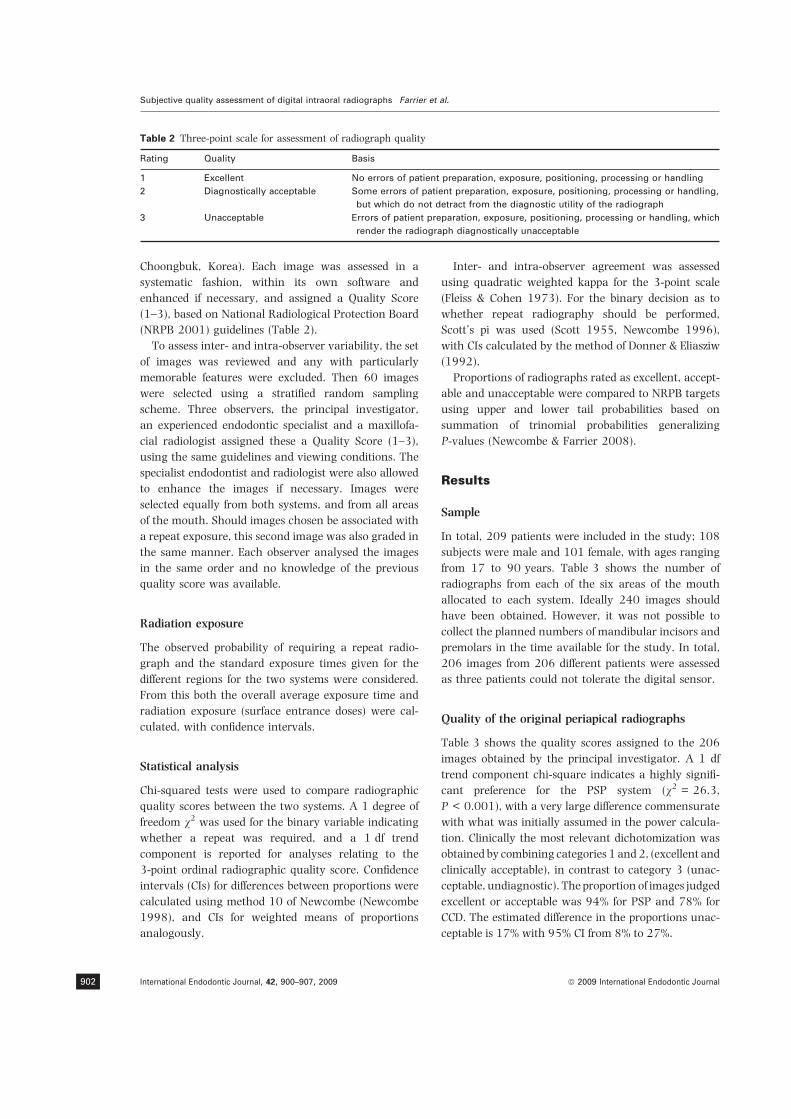
Choongbuk, Korea). Each image was assessed in a
systematic fashion, within its own software and
enhanced if necessary, and assigned a Quality Score
(1–3), based on National Radiological Protection Board
(NRPB 2001) guidelines (Table 2).
To assess inter- and intra-observer variability, the set
of images was reviewed and any with particularly
memorable features were excluded. Then 60 images
were selected using a stratified random sampling
scheme. Three observers, the principal investigator,
an experienced endodontic specialist and a maxillofa-
cial radiologist assigned these a Quality Score (1–3),
using the same guidelines and viewing conditions. The
specialist endodontist and radiologist were also allowed
to enhance the images if necessary. Images were
selected equally from both systems, and from all areas
of the mouth. Should images chosen be associated with
a repeat exposure, this second image was also graded in
the same manner. Each observer analysed the images
in the same order and no knowledge of the previous
quality score was available.
Radiation exposure
The observed probability of requiring a repeat radio-
graph and the standard exposure times given for the
different regions for the two systems were considered.
From this both the overall average exposure time and
radiation exposure (surface entrance doses) were cal-
culated, with confidence intervals.
Statistical analysis
Chi-squared tests were used to compare radiographic
quality scores between the two systems. A 1 degree of
freedom v2 was used for the binary variable indicating
whether a repeat was required, and a 1 df trend
component is reported for analyses relating to the
3-point ordinal radiographic quality score. Confidence
intervals (CIs) for differences between proportions were
calculated using method 10 of Newcombe (Newcombe
1998), and CIs for weighted means of proportions
analogously.
Inter- and intra-observer agreement was assessed
using quadratic weighted kappa for the 3-point scale
(Fleiss & Cohen 1973). For the binary decision as to
whether repeat radiography should be performed,
Scott’s pi was used (Scott 1955, Newcombe 1996),
with CIs calculated by the method of Donner & Eliasziw
(1992).
Proportions of radiographs rated as excellent, accept-
able and unacceptable were compared to NRPB targets
using upper and lower tail probabilities based on
summation of trinomial probabilities generalizing
P-values (Newcombe & Farrier 2008).
Results
Sample
In total, 209 patients were included in the study; 108
subjects were male and 101 female, with ages ranging
from 17 to 90 years. Table 3 shows the number of
radiographs from each of the six areas of the mouth
allocated to each system. Ideally 240 images should
have been obtained. However, it was not possible to
collect the planned numbers of mandibular incisors and
premolars in the time available for the study. In total,
206 images from 206 different patients were assessed
as three patients could not tolerate the digital sensor.
Quality of the original periapical radiographs
Table 3 shows the quality scores assigned to the 206
images obtained by the principal investigator. A 1 df
trend component chi-square indicates a highly signifi-
cant preference for the PSP system (v2 = 26.3,
P < 0.001), with a very large difference commensurate
with what was initially assumed in the power calcula-
tion. Clinically the most relevant dichotomization was
obtained by combining categories 1 and 2, (excellent and
clinically acceptable), in contrast to category 3 (unac-
ceptable, undiagnostic). The proportion of images judged
excellent or acceptable was 94% for PSP and 78% for
CCD. The estimated difference in the proportions unac-
ceptable is 17% with 95% CI from 8% to 27%.
Table 2 Three-point scale for assessment of radiograph quality
Rating Quality Basis
1 Excellent No errors of patient preparation, exposure, positioning, processing or handling
2 Diagnostically acceptable Some errors of patient preparation, exposure, positioning, processing or handling,
but which do not detract from the diagnostic utility of the radiograph
3 Unacceptable Errors of patient preparation, exposure, positioning, processing or handling, which
render the radiograph diagnostically unacceptable
Subjective quality assessment of digital intraoral radiographs Farrier et al.
International Endodontic Journal, 42, 900–907, 2009 ª 2009 International Endodontic Journal902

Repeat required for clinical purposes
Repeat exposures were actually performed for 27 (27%)
of 98 radiographs using the CCD system and 8 (7%) of
108 radiographs using the PSP system. This was
because the clinician in charge of the patients’ care
deemed some of the images unacceptable when SF
deemed them acceptable and vice versa. Nevertheless,
this 20% difference (95% CI 10% to 30%, v2 = 14.8,
P < 0.001) was closely in line with the results shown
in Table 3.
Quality of the repeat periapical radiographs
Analyses for the quality scores for the repeat radio-
graphs and whether a further repeat exposure was
required were restricted to 34 patients (Table 4). The
results of this showed a similar pattern to the original
radiographs but statistical significance was not reached
due to the very small sample size.
Quality scores in relation to area of dentition
Table 3 shows the quality scores of the original
periapical radiograph as graded by the principal inves-
tigator with regard to the area of the dentition. There
were marked differences (>20%) between the two
systems in favour of the PSP system, for all areas of
the dentition. The greatest differences were for maxil-
lary premolars and molars, and mandibular molars.
The observed overall difference in repeat rates
between the CCD and PSP systems needed slight
adjustment to allow for the imbalance in numbers of
radiographs taken in each area of the dentition. In the
maxillary arch the required samples of 20 incisors, 20
premolars and 20 molars were studied. However, in the
mandibular arch, this was not the case and fewer
subjects used the CCD system than the PSP system.
Therefore, a ‘balanced scorecard’, consisting of equal
numbers of radiographs in all areas of the dentition was
used to provide a more accurate representation. The
projected proportion requiring a repeat periapical
radiograph for the CCD system is 27% and for the
PSP system 6.8%, a difference of 20.2% (95% CI 10–
30%, v2 = 14.8, P < 0.001). It is therefore reasonable
to say that the difference between the two systems is
not substantially related to tooth type.
Inter- and intra-observer variability
Weighted kappa for the 3 point scale of quality of the
original images ranged from 0.46–0.72 for inter-
Table 3 Quality scores for the two radiography systems. These show the numbers of radiographs taken for each area of the
dentition, and the quality scores of the original periapical radiographs as assessed by the principal investigator
Radiography system Area of dentition
Number of
radiographs
Quality score
Excellent Acceptable Unacceptable
CCD Maxillary incisors 20 6 (30%) 13 (65%) 1 (50%)
Maxillary premolars 20 7 (35%) 11 (55%) 2 (10%)
Maxillary molars 20 8 (40%) 6 (30%) 6 (30%)
Mandibular incisors 7 3 (43%) 4 (57%) 0
Mandibular premolars 13 6 (46%) 2 (15%) 5 (38%)
Mandibular molars 18 6 (33%) 4 (22%) 8 (44%)
Total 98 36 (37%) 40 (41%) 22 (22%)
PSP Maxillary incisors 20 11 (55%) 7 (35%) 2 (10%)
Maxillary premolars 20 18 (90%) 2 (10%) 0
Maxillary molars 20 14 (70%) 5 (25%) 1 (5%)
Mandibular incisors 10 7 (70%) 3 (30%) 0
Mandibular premolars 18 11 (61%) 6 (33%) 1 (6%)
Mandibular molars 20 16 (80%) 2 (10%) 2 (10%)
Total 108 77 (71%) 25 (23%) 6 (6%)
CCD, charge-coupled device; PSP, photostimulable phosphor.
Table 4 Quality scores of repeat radiographs
Quality score
Radiography system
CCD PSP
Excellent 5 (20%) 5 (63%)
Acceptable 14 (54%) 2 (25%)
Unacceptable 7 (27%) 1 (13%)
Total 26 8
CCD, charge-coupled device; PSP, photostimulable phos-
phor.
Farrier et al. Subjective quality assessment of digital intraoral radiographs
ª 2009 International Endodontic Journal International Endodontic Journal, 42, 900–907, 2009 903

observer agreement and was 0.98 for intra-observer
agreement (SF), with broadly similar results for the
repeat radiographs.
For the binary outcome of whether a repeat radio-
graph was judged necessary, Scott’s pi ranged from
0.60 (95% CI 0.30–0.80) to 0.87 (95% CI 0.59–0.96)
for inter-observer agreement and was 1.0 (95% CI
0.76–1.0) for intra-observer agreement.
Performance targets
The 3 point quality scores for each system were
compared to the minimum target for radiographic
quality (‡70% excellent, £10% unsatisfactory) sug-
gested by the National Radiological Protection Board
(NRPB 2001). It is clear that the results obtained for
the CCD system fell short of these targets. Conversely,
the results obtained for the PSP system, with 71%
excellent and only 6% unsatisfactory, were ostensibly
slightly better than the ultimate target performance for
quality.
For the PSP system, the probability of observing
performance as good as, or better than, the observed
proportions of 71% excellent and 6% unacceptable,
assuming that in the underlying population the method
yields exactly 70% excellent and 10% unacceptable
quality of images, may be calculated as a summation of
multinomial probabilities. For these results, an upper
tail probability U = 0.058 was obtained, which repre-
sents the probability that results as good as or better
than those observed would arise if the true population
proportions were 70% excellent, 20% acceptable and
10% unacceptable. A corresponding lower tail proba-
bility of L = 0.64 was obtained, representing the
probability of results no better than those observed.
Both U and L use a mid-P accumulation of tail
probabilities (Lancaster 1949). A high value of L with
a low value of U indicates that the observed results
surpass the standard, whereas a high U and a low L
indicate results that fall short of the standard.
For the CCD system, U > 0.99 and L < 0.0001
which indicated strongly that the performance of this
system fell short of the target.
Radiation exposure
The physical characteristics of the X-ray machine used
(Siemens Heliodent DS, Bensheim, Germany) were
measured by the radiation physicist as part of the
annual radiation safety survey. The 60 kV machine
gave a dose rate at the end of the spacer cone of
5.98 mGy/s. Using this value an entrance doses for the
examinations was derived.
Based on a ‘balanced scorecard’ and disregarding
repeat exposures, the mean time of exposure of the CCD
system was 0.06 s. The expected additional exposure
due to the 27.6% risk of requiring a repeat exposure,
based on all areas of the dentition is 0.0171 s, with a
95% confidence interval of 0.0131–0.0232 s. Taking
account of the original periapical radiograph and a
single repeat if required, the average time for the CCD
system was 0.0771 s with a 95% CI from 0.0731 to
0.0832. This translated into an expected 0.46 mGy
radiation entrance dose, with a 95% CI of 0.44 to
0.50 mGy.
Similarly, for the PSP system the mean exposure time
averaged across the dentition was 0.1767 s. The
expected additional exposure due to the » 7.4% risk
of requiring a repeat was 0.0122 s, with a 95% CI from
0.0077 to 0.0274. Thus, taking into account the
original periapical radiograph and a single repeat if
required, the average exposure time with the PSP
system was 0.1889 s, with a 95% CI from 0.1844 to
0.2041. This translated into a 1.13 mGy expected
radiation surface dose, with a 95% CI of 1.10–
1.22 mGy.
Therefore, the difference in average exposure time
between the CCD and PSP systems based on the
balanced scorecard and taking into account the
original radiograph and repeat radiograph if required,
was estimated to be 0.1889–0.0771 = 0.1118 s, in
favour of the CCD system. The 95% confidence interval
for this difference is from 0.1042–0.1275 s. This
translated into a 0.67 mGy difference in expected
radiation surface dose with a confidence interval of
0.62–0.76 mGy.
Discussion
In this study comparing CCD and PSP systems in the
clinical environment, patients were allocated randomly
to a digital system and stratification methods used so
that each area of the dentition was uniformly exam-
ined. The principal investigator, a qualified dentist, was
responsible for exposing and assessing all the radio-
graphs and was blind to the system allocation until it
was disclosed in the clinical setting to ensure a more
fair comparison.
The subjective image quality rating score as des-
cribed by the NRPB was chosen since it is based on the
diagnostic potential of the image produced (NRPB
2001). This rating system is recommended when
Subjective quality assessment of digital intraoral radiographs Farrier et al.
International Endodontic Journal, 42, 900–907, 2009 ª 2009 International Endodontic Journal904

conducting audits based on the quality of radiographs
and is thus familiar and clinically relevant. Since this is
an established grading system used in the UK and by its
very nature is subjective no calibration of the investi-
gators was performed. Each investigator was familiar
with the grading scheme before the study commenced
and deemed whether the radiographs were diagnosti-
cally acceptable independently.
Various studies have been carried out which suggest
that digital equipment may improve the quality of
the image, especially if the contrast and density are
not optimum (Wenzel 1993, Gotfredsen et al. 1996,
Yoshiura et al. 1999, Svanaes et al. 2000, Li 2004).
Therefore, manipulation of the digital images was
allowed by all observers within the appropriate system
software, since this made the study more reminiscent of
the clinical environment. The same monitor was used
to view both types of image so that confounding screen
factors were not introduced. Each image was analysed
within its own software and it is possible that this could
lead to observer bias. An alternative approach would
have been to export the digital images to one common
viewing environment, as was done by Berkhout et al.
(2004), this would have made the observers blind to
the identity of the imaging systems. However, a more
realistic assessment was desired by enabling the
observers to manipulate the image within their own
software so as to simulate a true clinical situation. The
active areas of the CCD sensor and PSP imaging plates
are also different and thus masking the borders would
also have been required for all bias to be eliminated.
This would have resulted in some of the image from the
PSP systems being absent from view, since it has a
larger active pixel area and thus some vital radio-
graphic data could be prevented from being viewed and
this would have had a direct impact on the relevant
quality score.
The overall quality of the PSP system was found to be
significantly better than the quality of the images
produced with the CCD system. This agrees with Borg &
Grondahl (1996b) and Boscolo et al. (2001), but is the
opposite to that reported by de Almeida et al. (2003),
however, these studies were ex vivo and involved
imaging dried specimens with soft tissue equivalents
where control of radiographic positioning is more
consistent and reproducible. In addition, these studies
did not use the NRPB system for grading image quality.
There was a 20% difference between the two systems
in favour of the PSP digital system as to whether a
repeat image was required (95% CI 10–30%,
P < 0.001). This is potentially a very important benefit
since such a difference could have a marked influence
on the patient dose received, the ease at which the
process is carried out by both the patient and clinician
and the time taken for a successful radiological
examination.
Suggested explanations for the improved quality of
the PSP images and the less frequent need for a repeat
exposure can be sensibly combined. The CCD sensor is
far more bulky and stiff than the PSP imaging plates
and has a cable attached; it is also associated with a
larger sensor holder and beam aiming device. The CCD
sensor was found to be more difficult to position than
the PSP imaging plates. Patients susceptible to gagging
also found the CCD more difficult to tolerate than the
PSP sensor.
The active pixel area of the two sensors also differs,
which may be a contributing factor to the image
quality. The larger active image size of the PSP imaging
plates enables more information to be captured and a
greater probability that all the relevant information
required is actually recorded.
Difficulties in positioning CCD sensors have been
reported before (Wenzel & Moystad 2001, Berkhout
et al. 2002). In two surveys of dental practitioners,
there were significant problems with the positioning of
CCD sensors with an increase in the number of CCD
images taken compared with PSP systems (Wenzel &
Moystad 2001, Berkhout et al. 2002). In addition,
when compared to conventional film it has been shown
that there is an increase in the number of unsatisfactory
images with the CCD systems (Berkhout et al. 2003).
The ‘balanced scorecard’ allowed for the imbalance
in numbers throughout the areas of the dentition and
between the two digital systems. This gives a projected
difference of 20.2% between the CCD and PSP systems
in favour of the PSP system regarding whether or not a
repeat radiograph is required.
The CCD system did not reach the suggested NRPB
quality targets. The PSP system performed slightly
better than the ultimate targets. These performance
targets do not take into consideration the radiation
dose received by patients in order to eventually obtain
the correct diagnostic information.
The mean exposure time and radiation surface dose
for the PSP is greater than that for the CCD system by a
factor of 2.45. Therefore, despite the CCD system
requiring more repeat exposures, the radiation received
by the patient is less. In a questionnaire based survey
comparing CCD and PSP systems, CCD systems showed
a larger dose reduction in comparison to PSP imaging
plates (Berkhout et al. 2004). However, the authors
Farrier et al. Subjective quality assessment of digital intraoral radiographs
ª 2009 International Endodontic Journal International Endodontic Journal, 42, 900–907, 2009 905
also raised concerns that the radiation reduction may
be less than originally perceived as more CCD exposures
were carried out than PSP exposures. In the context of
the present study, it might have been possible to reduce
the mean exposure time without affecting the quality
for the PSP system, since the sensor has a very wide
exposure latitude; this is an area for further research. In
this study, if conventional radiographs or extraoral
radiographs were required because the patient could
not tolerate the sensor or there had been two failures
using the digital sensor the additional radiation expo-
sure was not included in the calculations.
Another study reported that the dose reduction as a
result of shorter exposure times exceeded the increase
in doses as a result of the greater number of radio-
graphs with both digital systems (Berkhout et al.
2003). However, with the CCD sensors the dose
reduction per exposure was almost cancelled out by
the increase in the number of radiographs taken. These
results are very different to the findings of the present
study.
Conclusion
The PSP Vistascan system produced significantly high-
er quality intraoral periapical images compared with
the CCD Sidexis system. The CCD system did not reach
the set performance targets of ‡70% excellent and
£10% unsatisfactory. There was also a significantly
higher repeat rate using the CCD system compared to
the PSP system. The mean exposure time and radiation
exposure for the PSP system is greater than for the CCD
system.
Acknowledgement
The authors are grateful to Paul Beere and his staff in
the dental radiology department for their help in this
research project.
References
de Almeida SM, de Oliveira AE, Ferreira RI, Boscolo FN (2003)
Image quality in digital radiographic systems. Brazilian
Dental Journal 14, 136–41.
Berkhout WE, Sanderink GC, Van der Stelt PF (2002) A
comparison of digital and film radiography in Dutch dental
practices assessed by questionnaire. Dentomaxillofacial Radi-
ology 31, 93–9.
Berkhout WE, Sanderink GC, Van der Stelt PF (2003) Does
digital radiography increase the number of intraoral radio-
graphs? A questionnaire study of Dutch dental practices.
Dentomaxillofacial Radiology 32, 124–7.
Berkhout WE, Beuger DA, Sanderink GC, van der Stelt PF
(2004) The dynamic range of digital radiographic systems:
dose reduction or risk of overexposure? Dentomaxillofacial
Radiology 33, 1–5.
Borg E, Grondahl HG (1996a) Endodontic measurements in
digital radiographs acquired by phostimulable storage
phosphor system. Endodontic Dental Traumatology 12, 20–4.
Borg E, Grondahl HG (1996b) On the dynamic range of
different X-ray photon detectors in intra-oral radiography. A
comparison of image quality in film, charge-coupled device
and storage phosphor systems. Dentomaxillofacial Radiology
25, 82–8.
Borg E, Grondahl K, Grondahl HG (1997) Marginal bone
level buccal to mandibular molars in digital radiographs
from charge-coupled device and storage phosphor systems.
An in vitro study. Journal of Clinical Periodontology 24,
306–12.
Borg E, Kallqvist A, Grondahl K, Grondahl HG (1998) Film
and digital radiography for detection of simulated root
resorption cavities. Oral Surgery Oral Medicine Oral Pathology
Oral Radiology & Endodontics 86, 110–4.
Borg E, Attaelmanan A, Grondahl HG (2000) Subjective image
quality of solid-state and photostimulable phosphor systems
for digital intra-oral radiography. Dentomaxillofacial Radiol-
ogy 29, 70–5.
Boscolo FN, Oliveira AE, Almeida SM, Haiter CF, Haiter Neto F
(2001) Clinical study of the sensitivity and dynamic range of
three digital systems, E-speed film and digitized film.
Brazilian Dental Journal 12, 191–5.
Cederberg RA, Tidwell E, Frederiksen NL, Benson BW (1998)
Endodontic working length assessment. Comparison of
storage phosphor digital imaging and radiographic film.
Oral Surgery Oral Medicine Oral Pathology Oral Radiology &
Endodontics 85, 325–8.
Donner A, Eliasziw M (1992) A goodness-of-fit approach to
inference procedures for the kappa statistic: confidence
interval construction, significance-testing and sample size
estimation. Statistics in Medicine 11, 1511–9.
Fleiss JL, Cohen J (1973) The equivalence of weighted kappa
and the intraclass correlation as measures of reliability.
Educational and Psychological Measurement 33, 613–9.
Gotfredsen E, Wenzel A, Grondahl HG (1996) Observers’ use of
image enhancement in assessing caries in radiographs taken
by four intra-oral digital systems. Dentomaxillofacial Radiol-
ogy 25, 34–8.
Kang BC, Farman AG, Scarfe WC, Goldsmith LJ (1996)
Observer differentiation of proximal enamel mechanical
defects versus natural proximal dental caries with computed
dental radiography. Oral Surgery Oral Medicine Oral Pathol-
ogy Oral Radiology & Endodontics 82, 459–65.
Lancaster HO (1949) The combination of probabilities arising
from data in discrete distributions. Biometrika 36, 370–82.
Subjective quality assessment of digital intraoral radiographs Farrier et al.
International Endodontic Journal, 42, 900–907, 2009 ª 2009 International Endodontic Journal906
Li G (2004) Comparative investigation of subjective image
quality of digital intraoral radiographs processed with 3
image-processing algorithms. Oral Surgery Oral Medicine
Oral Pathology Oral Radiology & Endodontics 97, 762–7.
Lim KF, Loh EE, Hong YH (1996) Intra-oral computed
radiography – an in vitro evaluation. Journal of Dentistry
24, 359–64.
Morner-Svalling AC, Tronje G, Andersson LG, Welander U
(2003) Comparison of the diagnostic potential of direct
digital and conventional intraoral radiography in the
evaluation of peri-implant conditions. Clinical Oral Implants
Research 14, 714–9.
Newcombe RG (1996) The relationship between chi-square
statistics from matched and unmatched analyses. Journal of
Clinical Epidemiology 49, 1325.
Newcombe RG (1998) Interval estimation for the difference
between independent proportions: comparison of eleven
methods. Statistics in Medicine 17, 873–90.
Newcombe RG, Farrier SL (2008) A generalisation of the tail-
based P-value to characterise the conformity of trinomial
proportions to prescribed norms. Statistical Methods in
Medical Research 17, 609–19.
NRPB (2001) Guidance Notes for Dental Practitioners on the
Safe Use of X-Ray Equipment. Department of Health,
London.
Scott WA (1955) Reliability of content analysis: the case of
nominal scale coding. Public Opinion Quarterly 19, 321–5.
van der Stelt PF (2005) Filmless imaging: the uses of digital
radiography in dental practice. Journal of the American Dental
Association 136, 1379–87.
Svanaes DB, Moystad A, Larheim TA (2000) Approximal
caries depth assessment with storage phosphor versus film
radiography. Evaluation of the caries-specific Oslo enhance-
ment procedure. Caries Research 34, 448–53.
Syriopoulos K, Sanderink GC, Velders XL, van der Stelt PF
(2000) Radiographic detection of approximal caries: a
comparison of dental films and digital imaging systems.
Dentomaxillofacial Radiology 29, 312–8.
Velders XL, Sanderink GC, van der Stelt PF (1996) Dose
reduction of two digital sensor systems measuring file
lengths. Oral Surgery Oral Medicine Oral Pathology Oral
Radiology & Endodontics 81, 607–12.
Versteeg CH, Sanderink GC, van Ginkel FC, van der Stelt PF
(1998) An evaluation of periapical radiography with a
charge-coupled device. Dentomaxillofacial Radiology 27, 97–
101.
Wenzel A (1993) Computer-aided image manipulation of
intraoral radiographs to enhance diagnosis in dental
practice: a review. International Dental Journal 43, 99–108.
Wenzel A, Borg E (1995) Accuracy of caries diagnosis in
digital images from charge-coupled device and storage
phosphor systems: an in vitro study. Dentomaxillofacial
Radiology 24, 250–4.
Wenzel A, Moystad A (2001) Experience of Norwegian general
dental practitioners with solid state and storage phosphor
detectors. Dentomaxillofacial Radiology 30, 203–8.
Yoshiura K, Kawazu T, Chikui T et al. (1999) Assessment of
image quality in dental radiography, part 1: phantom
validity. Oral Surgery Oral Medicine Oral Pathology Oral
Radiology & Endodontics 87, 115–22.
Farrier et al. Subjective quality assessment of digital intraoral radiographs
ª 2009 International Endodontic Journal International Endodontic Journal, 42, 900–907, 2009 907

Microflora in teeth associated with apicalperiodontitis: a methodological observationalstudy comparing two protocols and threemicroscopy techniques
N. Richardson, N. J. Mordan, J. A. P. Figueiredo, Y-L. Ng & K. GulabivalaUnits of Endodontology & Microscopy, Divisions of Restorative Dental Science and Biomaterials & Tissue Engineering, UCL
Eastman Dental Institute, University College London, London, UK
Abstract
Richardson N, Mordan NJ, Figueiredo JAP, Ng Y-L,
Gulabivala K. Microflora in teeth associated with apical
periodontitis: a methodological observational study comparing
two protocols and three microscopy techniques. International
Endodontic Journal, 42, 908–921, 2009.
Aim The aim of this study was to compare two
protocols to examine bacterial colonization in teeth
associated with chronic apical periodontitis with acute
episodes (ap), using light microscopy (LM), transmis-
sion electron microscopy (TEM) and scanning electron
microscopy (SEM).
Methodology Nine root samples (seven teeth) were
processed using either Eastman Dental Institute (EDI)
(n = 4 teeth/4 roots) or Zurich (n = 3 teeth/5 roots)
protocols. The roots were sectioned longitudinally; one
root portion was viewed with SEM, descriptively
dividing its length into apical, middle and coronal;
semi-thin and ultra-thin transverse sections were
viewed under LM and TEM from each third of the
other root portion. Each root was therefore examined
using all microscopy techniques. Observations of bac-
terial presence, description and distribution within the
root canal lumen and root dentine were systematically
recorded using pre-determined criteria.
Results The Zurich technique gave a more predict-
able division of the root, but the surface was slightly
smeared and demineralization was incomplete. The
Eastman Dental Institute (EDI) approach appeared to
provide better ultrastructural detail. Bacteria were
detected in eight of the nine roots. Bacterial biofilms
were commonly seen adhering to the root canal
surface, containing various cellular morphotypes: rods,
cocci, filaments and spirochaetes. Bacteria were more
evident apically than coronally, associated with the
canal wall but were more commonly evident coronally
than apically within the dentinal tubules. Polymorphs
(PMNs) were found in all the root thirds, especially
apically, often numerous and walling off the bacterial
biofilm from the remaining canal lumen.
Conclusions Both protocols had merits and de-mer-
its. The combination of microscopy techniques offered
complementary views of intra-radicular bacterial colo-
nization. The perception of confinement of the host/
microbial interface at the apical foramen is not entirely
correct; PMNs may be found even in the coronal third
of root canals containing necrotic pulp tissue.
Keywords: intra-radicular bacteria, microscopy, pro-
tocols, root canal.
Received 12 August 2008; accepted 25 March 2009
Introduction
The role of a polymicrobial infection of the root canal
system in apical periodontitis is well established
(Kakehashi et al. 1965, Sundqvist 1976, Fabricius
et al. 1982, Tani-Ishii et al. 1994) but deep insights
into the ecology and physiology of the bacterial
Correspondence: Professor Kishor Gulabivala, Unit of
Endodontology, UCL Eastman Dental Institute, 256 Grays
Inn Road, London WC1X 8LD, UK (Tel.: 020 7915 1033; fax:
020 7915 2371; e-mail: [email protected]).
doi:10.1111/j.1365-2591.2009.01594.x
International Endodontic Journal, 42, 908–921, 2009 ª 2009 International Endodontic Journal908

colonization remain elusive. Much of the current
knowledge of intra-radicular infection stems from
in vivo and ex vivo culture studies of sampled bacteria;
such approaches tend to bias the revealed micro-flora
(Akpata 1976, Kumar et al. 2002). The picture of
bacterial diversity is influenced by many factors,
including growth conditions, sub-culture strategy and
the nature of bacterial identification (Rolph et al. 2001,
Kumar et al. 2002, Munson et al. 2002, Gulabivala
2004). The number of detected and identified taxa per
tooth has increased from 1 to 12 cultured varieties up
to 20 phylotypes using culture-independent tech-
niques, with estimates of actual numbers up to 90
(Rolph et al. 2001, Munson et al. 2002). Whilst, the
known diversity of the microflora has increased with
improved culture techniques and culture-independent
techniques, direct microscopy suggests, as indeed it did
even in the time of Miller (1894) that a proportion of
the flora still remains uncultured. Furthermore, the
process of sampling disturbs insights about the intimate
and intricate relationships between bacteria and their
abiotic environment (Nair 1987).
Microscopically, bacterial strains are evident as cocci,
rods, filamentous or spiral morphotypes and have been
shown in a landmark paper to exist mainly in a biofilm
lining the root canal wall in the root apex (Nair 1987).
This paper provided the first real insight into the
morphological distribution of the root canal flora in the
root apex and its association with the host response.
Study of the excellent photo-micrographs provides
visual evidence to support the predicted ecological
and physical spatial relationships between bacteria
(Sundqvist 1992).
Different microscopy techniques possess different
properties and propensities to reveal the inherent
‘truth’ about the bacterial distribution and its struc-
ture. Light microscopy (LM) remains a useful base-line
technique to provide an overall perspective but lacks
resolution to reveal finer details. In contrast, trans-
mission electron microscopy (TEM) possesses the high
resolution to reveal ultra-structural details, losing
something of the perspective as a trade-off. Hence,
Nair used the approach he described as correlative LM
and electron microscopy studies to decipher both
aspects. Although not using the term ‘biofilm’, he
provided the first real detailed description of the root
canal biofilm within root apices, as it related to the
aetio-pathogenesis of apical periodontitis. The struc-
ture of the microflora within the entire tooth, as it
relates to approaches to treatment has been little
studied.
The validity of the observations made by microscopy
rests on the assumption that the processing stages have
accurately preserved the anatomical structures and
that the imaging system possesses the means and
resolution to highlight the relevant features. Knowl-
edge of imaging principles is essential but empirical
studies are also necessary to reveal the true in situ
potential of microscopy techniques. Distortion of tissues
and translocation of structural components are possible
but need to be minimized or else recognized as artefacts.
Detection of such artefacts may not be straightforward
but is an important element in the critical appraisal of
findings. To this end, the nature of sample fixation and
processing may also influence results.
The aim of this methodological observational study
was to compare different tooth processing protocols and
microscopy (LM, SEM and TEM) techniques to examine
bacterial colonization within the coronal, middle and
apical thirds of roots associated with apical periodon-
titis.
Materials and methods
Sample collection and storage
The material for this study consisted of extracted
human teeth with radiographically evident periapical
lesions (and associated acute episodes) and an absence
of periodontal disease or previous pulpal therapy. The
teeth were carefully extracted by General Dental
Practitioners with minimal pumping motion (Kapalas
et al. 2001, 2002) and immersed into tubes containing
3% glutaraldehyde (Agar Scientific, Stanstead, UK) in
0.1 mol L)1 sodium cacodylate (Agar Scientific) after
de-coronation with a sterile diamond bur. The sample
teeth were stored at 4 �C to provide a total fixation
period of 1 week. Informed consent had been obtained
from the patients prior to inclusion in the study pool;
seven teeth meeting the above criteria were selected for
the study.
Processing for microscopy
Two methods of sample processing were used: (i) the
EDI protocol (Vrahopoulos 1989), which involved
demineralization after embedding; and (ii) the Zurich
protocol (Nair 1987), which involved demineralization
before embedding. The seven selected teeth were ran-
domly assigned to the two processing groups; EDI
protocol (n = 4 teeth/4 roots with apical periodontitis)
and Nair protocol (n = 3 teeth/5 roots/4 roots with
Richardson et al. In situ microscopy of endodontic microflora
ª 2009 International Endodontic Journal International Endodontic Journal, 42, 908–921, 2009 909

apical periodontitis). An overview of the key stages in
the two processing protocols is shown in Fig. 1.
EDI protocol
Longitudinal splitting of the roots
The roots were grooved longitudinally using an ultra-
fine diamond disc (Metrodent, Huddersfield, UK) along
the narrowest surface of the root in a fume cupboard
(Labcaire, Clevedon, UK). The root was then firmly
pressed into unset lab putty (Optosil� and Xantopren�;
Heraeus Kulzer, Hanau, Germany) and allowed to set.
Splitting of the root was completed using an osteotome,
exposing the pulp canal space in both sections. The
section containing more hard tissue was used for the
LM and TEM examination, whilst the other half was
used for SEM examination.
Processing for SEM
The root halves allocated for SEM examination were
dehydrated in a graded series of alcohol (20%, 50%,
70%, 90% and 3· 100% for 10 min each), placed in
hexamethyldisilazane (HMDS) (TAAB Laboratories Ltd,
Reading, UK) for 5 min, then removed and left on filter
paper for 2–3 h for the HMDS to evaporate. The
samples were attached to aluminium SEM stubs (Agar
Scientific) using carbon conducting cement (Neubauer
Chemikalien, Munster, Germany) and sputter-coated
with gold/palladium in a Polaron E5000 Sputter
Coater (Quorum Technologies Ltd, Newhaven, UK).
Zurich protocolEDI protocol
Tooth split longitudinallywith an osteotome
Dehydrated
DehydratedSEMprocessing
SEMprocessing
Embeddedin resin
Embeddedin resin
Cut into 1 mmslices & placed
in EDTA
Ultra-thinsectioningfor TEM
Ultra-thinsectioningfor TEM
Semi-thinsectioning
for LM
Semi-thinsectioning
for LM
4 months later, teeth cutlongitudinally with razor blade
Re-dehydrated& re-embedded
Placed in EDTA
Cut into 4sections
Fixed in 3% glutaraldehydein 0.1% sodium cacodylate
Toothcollection
Apical
Coronal
Middle1 mm
Figure 1 Flow chart showing the succession of stages for each processing protocol.
In situ microscopy of endodontic microflora Richardson et al.
International Endodontic Journal, 42, 908–921, 2009 ª 2009 International Endodontic Journal910
The specimens were viewed in a Cambridge Stereoscan
90B (LEO Electron Microscopy Ltd, Cambridge, UK)
operating at 15 kV and digital images were captured
using i-scan2000 software (ISSGroup,Manchester, UK).
Processing for LM and TEM
The root halves allocated for LM and TEM were
dehydrated in a graded series of alcohol (20%, 50%,
70% and 3· 90% for 10 min each) and infiltrated with
LR White resin (The London Resin Company, London,
UK). This was performed in stages as follows: initial
immersion in LR White resin and 90% alcohol (ratio of
1 : 1) for 2 h at 4 �C; immersion in pure fresh LR
White for 30 min at 4 �C; immersion in fresh LR White
overnight (10–12 h) at 4 �C and the following morn-
ing, for 1 h, at 4 �C. The sections were embedded in
tinfoil containers (Buyrite UK Ltd, Aldershot, UK)
containing 20 mL of LR White and 30 lL LR White
accelerator. Air was excluded from the setting process
using parafilm (Agar Scientific) over the exposed resin
mix, which was polymerized for 1 h in the freezer, then
overnight at 4 �C and then removed to warm up to
room temperature.
The embedded roots were sliced transversely using a
high-speed diamond saw (Exact, Aberdeen, UK) into 1-
mm thick sections. The slices were decalcified in
0.15 mol L)1 EDTA in specimen tubes for 3–8 weeks
at room temperature on a tissue rotator at 2 rpm
(TAAB, Rotator type N; Agar Scientific). The EDTA
solution was changed every 2–3 days until the dentine
could be easily cut with a single edge carbon steel razor
blade (Agar Scientific). The slices were dehydrated
again and re-embedded in LR White resin as described
above.
Sectioning for LM
Semi-thin sections of 0.5 and 1 lm were cut with a
Diatome (Diatome AG, Biel, Switzerland) diamond knife
on an ultramicrotome (Reichert UltracutE; Cambridge
Instruments, Cambridge, UK). These were stained with
toluidine blue and used to check sample orientation
before proceeding with LM and TEM. Slides were
viewed on an Olympus BX50 optical microscope
(Olympus, Southall, UK).
Sectioning for TEM
Ultra-thin sections (90–100 nm) were cut using the
same technique, and collected on either carbon-form-
var coated copper 200 mesh grids (Agar Scientific) or
gold 400 mesh grids (Agar Scientific). The sections
were then stained on the grid with 0.4% (w/v) uranyl
acetate in absolute alcohol for 5 min, followed by
5 min in Reynold’s (1963) lead citrate. Sections were
examined on a TEM (100CXII; JEOL, Welwyn Garden
City, UK) operating at 80 kV and images were recorded
onto Kodak 4 EM film (TAAB Laboratories Ltd).
Zurich protocol
Demineralization
The roots were placed in 0.15 mol L)1 EDTA and
0.5% glutaraldehyde (Agar Scientific) in specimen
tubes on a tissue rotator at 2 rpm. Initially, the EDTA
solution was replaced every 2–3 days over 3 months,
and then changed everyday for the remaining
1 month. Progress was checked by carefully inserting
a single-edged carbon steel razor blade (Agar Scien-
tific) into the dentine, taking care not to penetrate to
the root canal.
Longitudinal cutting of the roots
After approximately 4 months in EDTA, the roots were
demineralized sufficiently to allow, gentle, controlled,
longitudinal cutting of the roots. At this point, one-half
of each root was randomly designated for SEM and the
other half for LM and TEM.
The root associated with the periapical lesion was
used from each tooth, except for tooth R6, a molar,
from which all three roots were used for comparison,
although only two were radiographically associated
with periapical lesions (R6 a, b – Table 1).
The root halves designated for SEM were dehydrated
to 100% ethanol, immersed in HMDS and allowed to
dry as for the EDI protocol, handling with greater care
because of the demineralization. Those samples due for
TEM examination were dehydrated to 90% ethanol and
embedded in LR White resin in the same manner as the
initial part of the EDI protocol without the necessity for
demineralization and re-embedding.
Selection of fields of view for both protocols
Scanning electron microscopy
The entire root half was first examined under low
magnification. Then, starting coronally, the root was
examined horizontally millimeter by millimeter, using
the lbar on the image as a guide. At each millimeter
level, the site of examination was magnified to ·5000.This horizontal scanning was repeated at the next
adjacent apical level until the entire root canal had
been traversed. Observations were made on this basis
and representative photographic images were recorded
Richardson et al. In situ microscopy of endodontic microflora
ª 2009 International Endodontic Journal International Endodontic Journal, 42, 908–921, 2009 911

or when bacterial colonization patterns worthy of note
were discerned.
Light microscopy
For the EDI protocol, 1-lm sections were cut from the
most coronal, middle and most apical slices of the root.
The Zurich protocol involved cutting the whole embed-
ded root into four equal corono-apical portions and
then 1-lm thick sections were cut from the coronal,
apical sections and from either of the two middle
sections (Fig. 1). Stained sections were examined to
verify presence of the canal in the section; upon
confirmation 5–7 sections of either 0.5 or 1 lm were
cut and examined at ·200, ·400 and ·1000 (oil
immersion) magnifications. Representative photo-
graphs were taken at both low and high magnification
for maintaining perspective and obtaining the highest
resolution.
Transmission electron microscopy
The LM findings informed the further sectioning for
TEM for both protocols. Two sections were cut and
examined from the same sites as for the LM sections for
each third of the root. The sections were initially
examined at the lowest magnification for perspective
before zooming in at higher magnifications. Photo-
graphic images were recorded at a number of magni-
fications to illustrate findings.
Comparison between EDI and Zurich protocols
The EDI and Zurich protocols were subjectively com-
pared using the following measures:
1 Ease of processing. This was judged by the ability to
split or section the root in a controlled manner to view
the root canal and its contents, as well as the time
taken for complete processing of the roots;
Table 1 Summary of viewable fields for each protocol (EDI/Zurich) and the presence/absence of bacteria by microscopy technique,
tooth, root and segment
Protocol
Root
no.
Root
portion
Periapical lesion
visible on
radiograph
SEM LM TEM
Lumen
Dentinal
tubules Lumen
Dentinal
tubules Lumen
Dentinal
tubules
EDI
protocol
R1 Coronal 4 · · · · · ·Middle 4 · · · · · ·Apical 4 o o · · · ·
R2 Coronal 4 4 · o o o o
Middle 4 4 4 o o o o
Apical 4 o o 4 · 4 ·R3 Coronal 4 · · o o o o
Middle 4 4 · 4 · – –
Apical 4 · · o o o o
R4 Coronal 4 4 · 4 4 4 4
Middle 4 4 · 4 4 4 4
Apical 4 4 4 4 · 4 ·Zurich
protocol
R5 Coronal 4 4 4 4 4 4 4
Middle 4 4 · 4 4 4 4
Apical 4 4 · 4 · 4 ·R6A Coronal 4 4 · 4 4 4 4
Middle 4 4 · 4 4 – –
Apical 4 4 · 4 · 4 ·R6B Coronal 4 · · 4 4 4 4
Middle 4 · · 4 4 – –
Apical 4 4 · 4 · - –
R6C Coronal · o o 4 4 4 4
Middle · · · 4 4 – –
Apical · · · · · · ·R7 Coronal 4 4 · 4 4 4 4
Middle 4 4 · 4 4 – –
Apical 4 4 · 4 4 4 4
4, bacteria detected; ·, Bacteria not detected; –, insufficient demineralization; o, canal not visible.
R6A, root; from tooth 6; root A.
In situ microscopy of endodontic microflora Richardson et al.
International Endodontic Journal, 42, 908–921, 2009 ª 2009 International Endodontic Journal912

2 Accuracy of findings. Note was made of actual or
apparent artefacts, distortion or evident bacterial
translocation.
Analysis of findings
Observational data were collected as systematically as
possible to build a coherent picture of the intra-
radicular infection, in particular highlighting any
common, surprising or unusual findings. An attempt
was made to record presence or absence and density of
bacteria as objectively as possible to enable comparison.
Simple descriptive statistics were used to analyse the
findings.
Results
Comparison of processing protocols
The principal difference between the processing for the
two protocols was the length of time to progress from
unfixed sample to SEM/TEM examination. The Zurich
protocol was several weeks longer than the EDI
protocol because of longer decalcification times. How-
ever, once demineralization was complete, the Zurich
protocol allowed more controlled and accurate bisect-
ing of the root, than the less predictable root splitting
required for the EDI protocol. Table 1 summarizes the
viewable fields for each protocol (EDI/Zurich) and the
presence/absence of bacteria by microscopy technique,
tooth, root and segment.
Comparison of techniques by SEM
From each root, one-half was prepared for SEM, four
from the EDI protocol and five from the Zurich
protocol. The tooth structure and root canal contents
observed in samples processed using the two protocols
were similar (Fig. 2) although it was noted that in
some of the Zurich samples the dentine surface had a
‘smeared’ appearance (Fig. 3). As a result of the more
accurate dividing of the root with the Zurich protocol,
there were more root portions, 14 of 15, in which the
root canal was visible as opposed to 10 of 12 with the
EDI protocol. In both of the EDI samples without a
visible canal, this occurred in the important apical
portion.
Translocation of root canal contents as a result of
processing was sometimes observed with both proto-
cols. On the cut (Zurich – Fig. 3) or fractured (EDI –
Fig. 6) dentine surface, this could be clearly discerned
as superficial cells and debris (Fig. 3) but within the
canal this was less easy to identify.
Bacterial cell morphology (rods, cocci and filaments)
was easily distinguished with SEM (Fig. 4), but only at
the sample surface, and the presence of a thick extra-
cellular matrix masked underlying bacteria. It was,
however, possible to discern the relative thickness of
D
D
CC
1 mm
Figure 2 R5 (Zurich protocol) SEM low magnification LS root
showing dentine (D), the root canal and cellular material (CC)
(lbar represents 1 mm).
D
60 μm
Figure 3 R5 (Zurich protocol) SEM showing the smeared
dentine and some translocated RBCs (arrows) (l bar represents
60 lm).
Richardson et al. In situ microscopy of endodontic microflora
ª 2009 International Endodontic Journal International Endodontic Journal, 42, 908–921, 2009 913
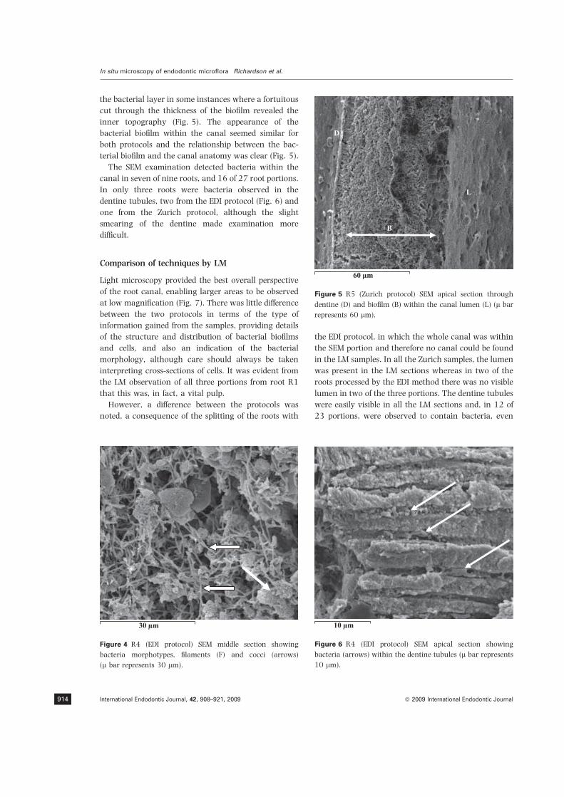
the bacterial layer in some instances where a fortuitous
cut through the thickness of the biofilm revealed the
inner topography (Fig. 5). The appearance of the
bacterial biofilm within the canal seemed similar for
both protocols and the relationship between the bac-
terial biofilm and the canal anatomy was clear (Fig. 5).
The SEM examination detected bacteria within the
canal in seven of nine roots, and 16 of 27 root portions.
In only three roots were bacteria observed in the
dentine tubules, two from the EDI protocol (Fig. 6) and
one from the Zurich protocol, although the slight
smearing of the dentine made examination more
difficult.
Comparison of techniques by LM
Light microscopy provided the best overall perspective
of the root canal, enabling larger areas to be observed
at low magnification (Fig. 7). There was little difference
between the two protocols in terms of the type of
information gained from the samples, providing details
of the structure and distribution of bacterial biofilms
and cells, and also an indication of the bacterial
morphology, although care should always be taken
interpreting cross-sections of cells. It was evident from
the LM observation of all three portions from root R1
that this was, in fact, a vital pulp.
However, a difference between the protocols was
noted, a consequence of the splitting of the roots with
the EDI protocol, in which the whole canal was within
the SEM portion and therefore no canal could be found
in the LM samples. In all the Zurich samples, the lumen
was present in the LM sections whereas in two of the
roots processed by the EDI method there was no visible
lumen in two of the three portions. The dentine tubules
were easily visible in all the LM sections and, in 12 of
23 portions, were observed to contain bacteria, even
30 μm
Figure 4 R4 (EDI protocol) SEM middle section showing
bacteria morphotypes, filaments (F) and cocci (arrows)
(l bar represents 30 lm).
D
B
L
60 μm
Figure 5 R5 (Zurich protocol) SEM apical section through
dentine (D) and biofilm (B) within the canal lumen (L) (l bar
represents 60 lm).
10 μm
Figure 6 R4 (EDI protocol) SEM apical section showing
bacteria (arrows) within the dentine tubules (l bar represents
10 lm).
In situ microscopy of endodontic microflora Richardson et al.
International Endodontic Journal, 42, 908–921, 2009 ª 2009 International Endodontic Journal914

when the bacterial film was sparse (Fig. 8). In 10 of
these, bacteria were found in the LM sections where
SEM had not found them, and in one, the opposite
occurred.
In some samples, it was observed that polymorphs
(PMNs) and some RBCs formed a layer several cells
thick over the bacterial biofilm (Fig. 9). This was
observed in two teeth and was most prominent in the
apical segments but less so in the middle and coronal
segments. In one root, a second bacterial biofilm
(although less dense) could be observed on the luminal
aspect of the PMN layer (Fig. 9), thus a layer of PMNs
was sandwiched between two bacterial biofilms.
Comparison of technique by TEM
As the same samples were used for both the semi-thick
LM and ultra-thin TEM sections, the reported absence
of a root canal in both was due to inadequate
demineralization. However, in five of the 15 root
portions processed by the Zurich technique, although
the dentine was demineralized sufficiently for the LM
sectioning, it was insufficient for the ultra-thin section-
ing and therefore these were not viewed by TEM. In
four of the five cases, this was a middle portion of the
root (Table 1).
In most cases, TEM provided similar information to
LM except that TEM conferred the considerable advan-
tage over the other techniques in the detail of visual
information available on the cells and bacteria. The
TEM of the biofilm in Figs 10 and 11 showed the close
arrangement and morphology of the cells, including
spirochaetes. Furthermore, the PMNs in this Zurich
processed sample (Fig. 11) appeared to be ‘leached’ of
100 μm
B
Figure 7 R5 (Zurich protocol) light microscopy (LM) apical
section showing the overall view. The canal wall has a thick
biofilm (B) with the luminal part containing some poorly
visible amorphous substance (l bar represents 100 lm).
10 μm
Figure 8 R4 (EDI protocol) LM middle section showing
bacteria (arrows) within the dentine tubules (l bar represents
10 lm).
30 μmm
D
I
B
B
Figure 9 R5 (Zurich protocol) LM apical section showing
bacterial biofilm (B) adherent to the canal surface and walled
in by PMNs and RBCs (I) beyond which there is a further
biofilm (l bar represents 30 lm).
Richardson et al. In situ microscopy of endodontic microflora
ª 2009 International Endodontic Journal International Endodontic Journal, 42, 908–921, 2009 915

cytoplasmic contents, whereas in EDI samples the
immune cells appeared healthy (Fig. 12).
When LM detected bacteria in the dentinal tubules,
this was confirmed by TEM, except for those samples
that were not sufficiently demineralized. In many of
these samples, there was an apparent attachment of
some bacteria to the collagen (Fig. 13) that must have
been present before demineralization and may indicate
exposed or available collagen epitopes within the
canal.
Summary of observations
The Zurich technique allowed examination of the root
canal in most SEM samples, all LM sections but only
half of the TEM sections. In contrast, for the EDI
technique, most of the canals were visible in the SEM,
but only three-quarters could be used for LM and TEM.
Generally, the correlation between LM and TEM was
good but SEM provided rather different information.
When bacteria were detected in the canal using LM or
TEM, their presence was not always found in the SEM
samples, although this may reflect the use of different
halves of the root canal for each type of technique.
D
Figure 10 R5 (Zurich protocol) transmission electron
microscopy (TEM) apical section showing bacterial biofilm
(B) extending from the canal surface with palisading of the
bacterial cells. The initial attachment to the canal dentine
wall (D) appears to be due to filamentous morphotypes with
coccal forms further out towards the canal lumen (TEM
·5000).
Figure 11 R5 (Zurich protocol) TEM apical section showing
the layer of PMNs (¤) and RBCs (*) covering the bofilm. Note
the loss of cellular contents from the PMNs (TEM ·2700).
C
Figure 13 R4 (EDI protocol) TEM middle section showing the
apparent attachment of a bacterium to the collagen fibres (C)
(TEM ·40 000).
Figure 12 R2 (EDI protocol) TEM coronal section a healthy
inflammatory cell, probably a lymphocyte, within the canal
lumen (TEM ·6700).
In situ microscopy of endodontic microflora Richardson et al.
International Endodontic Journal, 42, 908–921, 2009 ª 2009 International Endodontic Journal916

Bacteria were detected in eight of the nine roots
examined, including root R6C, apparently not associ-
ated with a periapical lesion, but bacteria were not
found in root R1, which although positive for presence
of periapical lesion, was found to be a vital pulp. The
pooled data from all microscopy techniques (Table 1)
showed that in the bacteria-positive teeth, bacteria
were detected in the canal lumens in all the root
segments except 3 (R3 coronal and apical; R6c apical).
In contrast, they were less frequently detected in the
dentinal tubules, especially in the apical portions, and
detection was more accurate by LM and TEM tech-
niques.
The pattern of bacterial distribution, both in the
canal lumen and on the canal walls, varied enormously
both from root to root and within each root. Contin-
uous biofilms were only evident in teeth with grossly
carious exposures and continuous communication
with the oral environment. The structure, thickness
and morphotypic composition varied considerably. The
bacterial biofilm was mainly evident on the canal wall
with interspersed bacterial aggregates in what seemed
to be residual necrotic pulp tissue. Sometimes bacterial
cells seemed to be present in the canal lumen in
apparent isolation (perhaps planktonic forms). In teeth
with intact pulp chambers, the canal lumen appeared
empty but was filled with some amorphous material
(Fig. 7). In some teeth, the relative abundance of
detectable bacteria was greater coronally, usually
associated with carious crowns. Rarely did the middle
portion have the greater abundance but, in teeth with
intact pulp chambers, the relative abundance of bac-
teria was greater in the apical segments. Each tooth
seemed to have its own variation of infection pattern.
The patterns of colonization of the dentinal tubules
appeared to follow relatively more predictable but
nevertheless variable behaviour. Dentinal tubules usu-
ally appeared to be colonized as a continuation of the
canal wall infection, although the diversity of morpho-
types were more restricted. Other instances showed
variable colonization of adjacent tubules sometimes
with highly dense colonization of the tubules in the
predentine with reducing density of colonization fur-
ther away from the canal lumen into the dentine.
The observation regarding the presence and close
association of PMNs and sometimes RBCs with bac-
terial aggregates and films was not consistent. It was
more prominent in some teeth than others and, where
present, was always observed in the apical portions
and frequently in the middle and coronal portions. In
one tooth, a second bacterial biofilm, although less
dense, was observed on the luminal aspect of the PMN
layer, implying that this was not a result of tooth
preparation.
Discussion
The prime purpose of this study was to evaluate the
utility of different microscopy techniques and protocols
to gain visual insights into the presence, distribution
and structure of bacterial colonization in teeth associ-
ated with apical periodontitis, regardless of the clinical
condition of the tooth; the intention was to use a wide
selection of tooth conditions meeting selection criteria
to evaluate the breadth of morphotypic bacterial
diversity. Many studies on the microflora of infected
roots have used teeth with gross caries, presumably
because of their easier availability (Nair 1987, Baum-
gartner & Falkler 1991, Sen et al. 1995). An additional
clinical parameter in this study was the acute presen-
tation of the selected teeth. A subsidiary but important
aim was to compare two tooth processing protocols.
The importance of this aspect is that the validity of
microscopy observations rest on accurate preservation
of the in situ anatomical structures and relationships.
Distortion of tissues or translocation of structural
components may obscure the ‘truth’, and they cor-
rectly need to be recognized as artefacts. The problem
for the observer is to be able to distinguish real from
artefact without a ‘positive control’. To be able to do so
requires a good appreciation of what is to be expected
based on understanding of biology, familiarity with the
technical aspects of the procedures and critical inter-
pretation. Purely morphological studies are able to give
morphological insight but cannot enable dissection of
the relationships and roles of bacterial species and their
interaction with host cells. Such insights may only be
obtained in the future through in situ labelling studies,
which require the preservation or exposure of target
cell surface, structural or chemical elements (Lam et al.
2000, Tan et al. 2000); the preserving protocols
therefore become important. The purpose of this study
was not to explore the effect of protocols on such cell
surface targets but to evaluate the effect of such
protocols on normal structural viewing, in the first
instance. Studies on in situ hybridization will be
reported separately. Another key factor is that each
microscopy technique requires an independent section;
the same section may not be viewed by all techniques.
Absolute comparison between microscopy techniques is
therefore impossible and relative comparison reliant on
viewing adjacent sections that are thin enough to
Richardson et al. In situ microscopy of endodontic microflora
ª 2009 International Endodontic Journal International Endodontic Journal, 42, 908–921, 2009 917

represent, more-or-less, the same structures. This was
more easily possible for LM/TEM views than for SEM,
because, of necessity, the opposite halves were viewed
and these could theoretically have different bacterial
colonization, particularly in teeth with intact pulp
chambers.
Some key features of difference between the protocols
bear discussion. Previous microscopy studies have split
their test teeth using a technique similar to the EDI
protocol (Lin & Langeland 1981, Molven et al. 1991,
Sen et al. 1995) but none commented on its inherent
problem of unpredictability; a feature mostly reduced
by practicing on spare rather than sample teeth.
Furthermore, the lack of comment may reflect that
the studies could select from both halves, whereas in
the present study, the portion with the larger canal
component was reserved for LM and TEM, theoreti-
cally compromising that used for SEM. Numerous
approaches have been used to split teeth and alter-
native methods have been reported (Rapp 1985) but
without tested consensus. The Zurich protocol was
favoured for its more predictable cutting of the demin-
eralized root compared with the splitting of mineralized
tissues in the EDI protocol. The predictable cuts in the
Zurich protocol were, however, associated with an
apparently smeared appearance of the dentine, in
contrast to the rougher fractured surface produced by
the EDI protocol (Fig. 3 vs. Fig. 6); the significance of
this feature is unknown although it may affect an
appraisal of dentine tubule content. It should be added
that such a feature was absent in the published
material from the Zurich laboratory and could be a
feature of adaptation in another laboratory.
A further putative advantage of the Zurich protocol
is that the natural morphological relationships and
conjunction of the structures would be less likely to be
disturbed. In contrast, in the EDI protocol, the various
washings of the pre-split and open canal surface prior
to sputter-coating could potentially result in transloca-
tion of ‘loose’ structures such as planktonic bacteria or
pulp debris (Nair 1987, and personal communication)
(Fig. 3). Translocated debris and bacteria are some-
times evident in publications using the SEM (Sen et al.
1995). In general though, the SEM views did not seem
much distorted or different between the protocols in
this study. Furthermore, the enmeshed and matted
appearance of the bacterial biofilm was confirmed by
the different microscopy techniques and appeared to
suggest that at least this feature of the bacterial
colonization remained preserved regardless of the
protocol used.
The careful and slow approach used by Nair (1987)
to demineralize the test specimens is laudable and is
most likely to yield accurate images representing the
‘truth’, nevertheless, within the time constraints
imposed in this study, the slower process resulted in
several middle root segments remaining un-demineral-
ized and therefore un-viewable (Table 1). The counter-
argument against the Zurich protocol was that the
more aggressive demineralization, albeit slower, and
associated long fixation periods, may damage surface
antigens (Hobot & Newman 1991) and probe targets
for in situ hybridization (Binder 1992).
It would be intuitively expected that each microscopy
technique with its own unique characteristics would
yield different perspectives on the objects under scru-
tiny; each hopefully yielding unique accuracy in some
way so that they together complement findings to build
a more accurate overview. The findings of this study
confirm these expectations and potential, whilst at the
same time highlighting the advantages and disadvan-
tages of each microscopy technique.
The SEM, with its propensity for revealing surface
topography was generally useful for deciphering detail
over the entire canal surface, whilst retaining contex-
tual perspective at lower magnifications; this also
enabled the proportion of the surface colonized to be
estimated. The technique was also useful for describing
cell morphotypes but by the same token, surface
coverage with cells or extra-cellular matrices precluded
revelatory insight into biofilm structure and relation-
ships.
The LM provided an excellent overview of the
collective bacterial colonization and its variation from
site to site within the selected section, particularly on
the canal wall. Its main limitation is the level of
magnification and resolution necessary to determine
inter-cellular and cellular-abiotic relationships. Fur-
thermore, morphotypic differentiation was relatively
gross and lacked discriminatory detail.
Transmission electron microscopy was the most
discriminating technique for providing fine detail of
the microflora and its relationship to adjacent struc-
tures, as well as cell-to-cell contacts. Furthermore, the
internal cellular morphology was also most clearly seen
by TEM.
It is evident that correlative studies using LM and
TEM provide the best conjunction, as reported by Nair
(1987). Furthermore, the combination with SEM pro-
vides further insights but the processing required is
different from that for LM and TEM and may be more
prone to distortion of surface detail.
In situ microscopy of endodontic microflora Richardson et al.
International Endodontic Journal, 42, 908–921, 2009 ª 2009 International Endodontic Journal918

The pictures of bacterial quantity and density were
broadly comparable between the microscopy tech-
niques (Table 1), confirming the utility of using adja-
cent serial sections for LM and TEM. However,
differences were sometimes apparent, both between
sections, and by microscopy technique, the latter
mainly because of SEM sections, which would by
definition have viewed geographically different loca-
tions from those viewed by LM or TEM.
Bacteria were not detected in one root apparently
associated with a periapical lesion, otherwise, a variety
of morphotypes were found in all canal segments
consisting of cocci, rods, filaments, spiral forms and
yeasts. The existence of a periapical lesion associated
with an inflamed but vital pulp is not a novel finding.
The present study found that of all the roots which
could be examined fully, only one had fewer bacteria
apically than coronally. In the other roots (including
those with intact pulp chambers), there was a transi-
tion from the coronal segment to the apical segment, of
greater relative bacterial abundance apically. This
contrasts with other work (Shovelton 1964), where
the sample was also made up of both open and closed
pulp systems. There was a lack of consistency in the
middle root segments, where some roots had fewer
bacteria than either the coronal or apical segments and
others where the bacterial abundance formed a con-
tinuous transition from coronal to apical. The distri-
bution could potentially be explained by abundance of
nutritive sources coronally and apically. A carious
exposure may allow seepage of salivary components
from the coronal aspect, forming a diffusion gradient
towards the apex. Once the bacteria are established
apically, the stimulation of inflammation apically may
then play a part in deriving nutrition from the
inflammatory serum exudate (Khot et al. 2004). The
relative scarcity of bacteria in the middle segment could
be explained by its farthest location from opposing
sources of nutrition (coronal or apical); it being the
lowest point on two opposing gradients. The evidence
of dividing bacterial cells in the middle segments
suggests the presence of sufficient nutrients in this part
of the canal at some point. In some species, such as
staphylococci, divided cells may remain joined for some
time after division.
The patterns of bacterial distribution in the canal
lumen and on canal walls varied. Some teeth had
discontinuous biofilms together with variable density
and layers of cells, whilst others had thick continuous,
dense biofilm layers. The structure, thickness and
morphotypic composition also varied considerably but
the species diversity of the flora may only be speculated
upon without in situ hybridization. Some niches in the
root canal seemed apparently more suited to biofilm
growth than others, although the main bacterial colo-
nization seemed to be on the canal walls; that within the
lumen, in the middle and coronal segments, seemed
more scattered. It is not known whether these bacteria,
apparently ‘floating’ without attachment represent
planktonic phenotypes or are biofilm phenotypes
attached to a ‘surface’ of degrading tissue that is invisible
in the chosen microscopy technique. Each tooth seemed
to have its own variation of infection, corroborating the
findings of various culture and culture-independent
studies (Sundqvist 1976, Rolph et al. 2001, Munson
et al. 2002). The impression in some teeth was that,
indeed this was a nutrient-depleted environment but in
others, the canal system appeared to be nutrient-rich
with active bacterial growth and propagation. It is
possible that acute apical symptoms may be due to such
rapid and proliferative bacterial growth rather than
because of specific species. Associations between species
and acute symptoms although often made, have not
proved fruitful, because the presence of the same species
can be confirmed in asymptomatic teeth. The answers
may lie in strain variation.
Yeast cells were detected in 3/7 (43%) teeth in this
study, a value that fits within the range previously
reported: by microscopy, 8–40% (Molven et al. 1991,
Sen et al. 1995); by culture, 5–55% (Slack 1975, Egan
et al. 2002); and by molecular detection, 21% (Baum-
gartner et al. 2000). Yeasts have been implicated in
failed cases, raising the suggestion that reduction of
bacteria during treatment may allow yeasts to over-
grow and predominate in the low-nutrient environ-
ment (Sundqvist 1992).
Bacterial invasion of dentinal tubules was predom-
inantly seen in the coronal and middle root segments;
in contrast Sen et al. (1995) reported dentinal tubule
invasion in the middle and apical root segments. The
presence of bacteria on inter-tubular dentine casts
some doubt on the SEM findings. The findings in the
apical root segments are consistent with reports of
fewer dentinal tubules in this region (Mjor et al. 2001).
Dentinal colonization was heaviest in the pre-dentine
and mainly confined towards the canal lumen end of
tubules than the cementum; in agreement with some
(Shovelton 1964, Nair 1987) but contradicting others
(Peters et al. 2001). The finding of apparent bacterial
association or attachment to dentine collagen (Fig. 13)
would appear to be in situ confirmation of the sugges-
tion previously made by Love & Jenkinson (2002).
Richardson et al. In situ microscopy of endodontic microflora
ª 2009 International Endodontic Journal International Endodontic Journal, 42, 908–921, 2009 919

Another interesting finding in the present study was
the presence of PMNs in all thirds of the roots with
necrotic pulps; the finding was particularly surprising
in the coronal segments but would be consistent with
pus exudation into the canal. Nair (1987) had previ-
ously reported PMNs amongst bacteria in the apical
sections of roots associated with apical periodontitis,
but these were described as isolated wandering cells.
Their presence was explained by virtue of chemotactic
signals from intra-canal bacteria. The extensive pres-
ence of PMNs in the root canals of teeth associated with
apical periodontitis (with acute episodes), apparently
strategically attempting to ‘wall off’ the bacterial
biofilm adherent to the canal wall was unexpected
and unique in the endodontic published literature. The
observation which was consistent between LM/TEM
techniques and different teeth and roots, alters the
perception of the root canal ecology in such acute
cases. First, it implies the presence of sufficient moisture
or a water-saturated medium through which they can
propel themselves to such distances into the canal.
Second, there should be sufficient nutrients to allow
them to migrate and survive in such locations (‘tech-
nically’ beyond the viable part of the body), bearing in
mind their short life-span [3–4 days (Taussig 1984)].
Third, it changes the perception of the host/microbial
interface as being confined to the apical foramen.
Clearly, at least one branch of this host/microbial
interaction is capable of extending into the length of the
necrotic, infected canal associated with symptoms.
Given the short life span of PMNs, the growth of a
bacterial biofilm on the luminal aspect of the layer of
PMNs suggests a very dynamic ecological niche in such
a tooth. The relative equality between the protocols, at
least in terms of quality of viewable sections, opens the
doors towards use of microscopy with immuno-label-
ling to further dissect the root canal ecology and the
dynamics of infection. The PMNs would appear to play
an important role in apical periodontitis and perhaps
apical healing.
Conclusions
The Zurich protocol was more predictable than the EDI
protocol in creating longitudinal sections and possibly
bacterial detection by microscopy but the quality of
observed sections seemed equivalent. Each microscopy
technique provided a unique perspective and together
allowed complementary synthesis of the presence and
morphological distribution of bacteria within roots.
Each tooth presented a unique pattern of bacterial
infection but all exhibited bacterial biofilms on canal
walls; 8/9 roots showed bacteria. Bacteria in the canal
lumen were often associated with other structures but
sometimes appeared ‘free-floating’. In general, bacteria
appeared more abundant apically than coronally but
dentinal tubule colonization was more common in
coronal and middle thirds. PMNs were often found
‘walling off’ bacterial biofilm along the entire length of
the root canal wall, although they were in higher
numbers apically. The findings provide interesting
insights into the nature of host/microbial interaction
and the ecology of infected root canals.
Acknowledgement
The authors are grateful to Dr PNR Nair for his
generous advice on the adoption of the Zurich protocol,
as well as on the finer points of microscopy.
References
Akpata ES (1976) Effect of endodontic procedures on the
population of viable microorganisms in the infected root
canal. Journal of Endodontics 2, 369–73.
Baumgartner CJ, Falkler WA (1991) Bacteria in the apical
5 mm of the infected root canals. Journal of Endodontics 17,
380–3.
Baumgartner JC, Watts CM, Xia T (2000) Occurrence of
Candida albicans in infections of endodontic origin. Journal of
Endodontics 26, 695–8.
Binder M (1992) In situ hybridization at the electron microscope
level. In: Wilkinson DG, ed. In Situ Hybridization – A Practical
Approach. Oxford: Oxford University Press, 105–20.
Egan MW, Spratt DA, Ng Y-L, Lam JM, Moles DR, Gulabivala K
(2002) Prevalence of yeasts in saliva and root canals of
teeth associated with apical periodontitis. International
Endodontic Journal 35, 321–9.
Fabricius L, Dahlen G, Holm G, Moller AJR (1982) Influence of
combination of oral bacteria on periapical tissues of mon-
keys. Scandinavian Journal of Dental Research 90, 200–6.
Gulabivala K (2004) Species Richness of Gram-Positive Coccoid
Morphotypes Isolated from Untreated and Treated Root Canals of
Teeth Associated with Periapical Disease. PhD Thesis. London:
University of London.
Hobot JA, Newman GR (1991) Strategies for improving the
cytochemical and immunocytochemical sensitivity of ultra-
structurally well-preserved, resin embedded biological tissue
for light and electron microscopy. Scanning Microscopy
Supplement 5, S27–40.
Kakehashi S, Stanley HR, Fitzgerald W (1965) The effects of
surgical exposures of dental pulps in germ-free and con-
ventional laboratory rats. Oral Surgery, Oral Medicine, and
Oral Pathology 20, 340–9.
In situ microscopy of endodontic microflora Richardson et al.
International Endodontic Journal, 42, 908–921, 2009 ª 2009 International Endodontic Journal920

Kapalas A, Spratt DA, Ng Y-L, Gulabivala K (2001) An in vitro
investigation of the bulk flow of fluid through apical
foramina during simulated tooth extraction: a potential
confounder in microbiological studies? International End-
odontic Journal 34, 335.
Kapalas A, Spratt DA, Ng Y-L, Gulabivala K (2002) Investi-
gation of bulk flow of bacterial suspension through apical
foramina during simulated tooth extraction. International
Endodontic Journal 35, 83.
Khot A, Spratt DA, Ng Y-L, Gulabivala K (2004) Utilisation of
relevant nutritional resources by root canal isolates. Inter-
national Endodontic Journal 37, 345–6 (abstract).
Kumar T, Spratt DA, Ng Y-L, Gulabivala K (2002) A
preliminary evaluation of a new method for sampling the
intra-radicular bacterial flora. International Endodontic Jour-
nal 35, 85.
Lam JM, Gulabivala K, Barrett W, Speight P, Smallwood E,
Spratt DA (2000) The identification of bacteria in dental
histological specimens using molecular methods. Interna-
tional Endodontic Journal 33, 73.
Lin L, Langeland K (1981) Light and electron microscopic
study of teeth with carious pulp exposures. Oral Surgery,
Oral Medicine,and Oral Pathology 51, 292–316.
Love RM, Jenkinson HF (2002) Invasion of dentinal tubules by
oral bacteria. Critical Reviews in Oral Biology and Medicine
13, 171–83.
Miller WD (1894) An introduction to the study of the bacterio-
pathology of the dental pulp. Dental Cosmos 36, 505–28.
Mjor IA, Smith MR, Ferrari M, Mannocci F (2001) The
structure of dentine in the apical region of human teeth.
International Endodontic Journal 34, 346–53.
Molven O, Olsen I, Kerekes K (1991) SEM of bacteria in the
apical 5 mm of infected root canals in permanent teeth with
periapical lesions. Endodontics and Dental Traumatology 7,
226–9.
Munson M, Pitt-Ford T, Chong B, Weightman A, Wade WG
(2002) Molecular and cultural analysis of the microflora
associated with endodontic infections. Journal of Dental
Research 81, 761–6.
Nair PN (1987) Light and electron microscopic studies of root
canal flora and periapical lesions. Journal of Endodontics 13,
29–39.
Peters LB, Wesselink PR, Buijs JF, van Winkelhoff AJ
(2001) Viable bacteria in root dentinal tubules of
teeth with apical periodontitis. Journal of Endodontics 27,
76–81.
Rapp R (1985) A procedure for splitting human teeth to
obtain intact pulp tissue, enamel and dentin. Stain Technol-
ogy 60, 39–43.
Reynolds ES (1963) The use of lead citrate at high pH as an
electron-opaque stain in electron microscopy. Journal of Cell
Biology 17, 208–12.
Rolph HJ, Lennon A, Riggio MP et al. (2001) Molecular
identification of microorganisms from endodontic infections.
Journal of Clinical Microbiology 39, 3282–9.
Sen BH, Piskin NB, Demirci T (1995) Observation of bacteria
and fungi in infected root canals and dentinal tubules by
SEM. Endodontics and Dental Traumatology 11, 6–9.
Shovelton DS (1964) The presence and distribution of micro-
organisms within non-vital teeth. British Dental Journal 117,
101–7.
Slack G (1975) The resistance to antibiotics of microorgan-
isms isolated from root canals. British Dental Journal 18,
493–4.
Sundqvist G (1976) Bacteriologic Studies of Necrotic Dental
Pulps. PhD Dissertation. Umea, Sweden: University of Umea.
Sundqvist G (1992) Associations between microbial species in
dental root canal infections. Oral Microbiology and Immunol-
ogy 7, 257–62.
Tan L, Spratt DA, Lam JM, Speight P, Gulabivala K (2000) The
effect of tissue-fixation conditions on the amplification of
16S rRNA genes from paraffin-embedded teeth using
polymerase chain reaction (PCR). International Endodontic
Journal 33, 166–7.
Tani-Ishii N, Wang CY, Tanner A, Stashenko P (1994)
Changes in root canal microbiota during the development of
rat periapical lesions. Oral Microbiology and Immunology 9,
129–35.
Taussig MJ (1984) Chapter 1 – inflammation. In: Taussig MJ,
ed. Processes in Pathology and Microbiology, 2nd edn. Oxford,
England: Blackwell Scientific Publications, pp. 15.
Vrahopoulos TP (1989) Ultrastructure of the Periodontal Lesion
in a Case of Papillon-Lefevre Syndrome (PLS). PhD Thesis.
London: University of London.
Richardson et al. In situ microscopy of endodontic microflora
ª 2009 International Endodontic Journal International Endodontic Journal, 42, 908–921, 2009 921

An in vivo experimental model to assess furcallesions as a result of perforation
M. J. B. Silva1, M. V. Caliari3, A. P. R. Sobrinho2, L. Q. Vieira1 & R. M. E. Arantes3
1Departamento de Bioquımica e Imunologia, Instituto de Ciencias Biologicas, Universidade Federal de Minas Gerais, Belo
Horizonte, MG, Brazil; 2Departamento de Odontologia Restaurativa, Faculdade de Odontologia, Universidade Federal de Minas
Gerais, Belo Horizonte, MG, Brazil; and 3Departmento de Patologia Geral, Instituto de Ciencias Biologicas, Universidade Federal de
Minas Gerais, Belo Horizonte, MG, Brazil
Abstract
Silva MJB, Caliari MV, Sobrinho APR, Vieira LQ, Arantes
RME. An in vivo experimental model to assess furcal lesions as
a result of perforation. International Endodontic Journal, 42,
922–929, 2009.
Aim To design and validate a rat molar model of
furcal perforation to allow investigation of the biolog-
ical phenomena that follow and to explore its potential
for evaluating repair materials under standardized
conditions.
Methodology Eighteen male Wistar rats were used.
Surgical aseptic procedures were carried out in order to
open the pulp chamber of a first molar tooth. A cavity
was prepared on the floor of the pulp chamber using a
¼ round bur that created a communication between
the furcation and the periodontal tissues. Six animals
for each time point were sacrificed on days 14, 21 and
28 to assay morphological changes at the furcation
region of molars. Maxillary bone was processed,
removed and sectioned. Cellular infiltration, collagen
deposition and bone resorption were assessed by
histological analysis. Cellularity in the lesion area was
determined by morphometric analysis. Data were
analysed using parametric Student’s t-test.
Results A furcal perforation model was standardized
in which both radiological outcome and periodontal
tissue reactions could be assessed through evaluation of
cellularity, osteoclast activity and collagen deposition.
The morphometric analysis revealed a greater number
of cells 21 day post-surgery when compared with
14 days.
Conclusion This animal model was suitable for
radiological and histological evaluation of the processes
that accompany surgical furcal perforation.
Keywords: animal models, biomaterials, furcal per-
forations.
Received 3 September 2008; accepted 14 April 2009
Introduction
Accidental root canal or furcal perforation complicates
the treatment and compromises the outcome of root
canal treatment (Seltzer & Bender 1990, Walton &
Torabinejad 2002). The prognosis of treatment of
perforations is dependent on site, size, setting time of
the repair material, and the efficacy of the material in
termsof to seal (Walton&Torabinejad2002).All of these
factors are related to the ability to prevent or eliminate
bacterial infiltration (Daoudi & Saunders 2002).
The chronic inflammatory reaction after accidental
furcal perforation has been the object of several studies
(Bhaskar & Rappaport 1971, Meister et al. 1979,
Beavers et al. 1986, Seltzer & Bender 1990, Balla et al.
1991, Arens & Torabinejad 1996, Wu et al. 2005,
Vajrabhaya et al. 2006, Al-Daafas & Al-Nazhan
2007,). This inflammatory reaction provokes alveolar
bone damage around the perforation site where bone is
progressively substituted by granulation tissue. The
Correspondence: Rosa Maria Esteves Arantes, MD, PhD,
Laboratorio de Neuro-imunopatologia Experimental, Departa-
mento de Patologia Geral, Instituto de Ciencias Biologicas,
Universidade Federal de Minas Gerais, Av. Antonio Carlos,
6627, 31270-901, Belo Horizonte, MG, Brazil (Tel.:
+5531 3409 2896/2884; fax: +5531 3409 2879; e-mail:
doi:10.1111/j.1365-2591.2009.01595.x
International Endodontic Journal, 42, 922–929, 2009 ª 2009 International Endodontic Journal922
lack of bone tissue leads to loss of periodontal attach-
ment that can affect tooth stability (Arens & Torabine-
jad 1996, Wu et al. 2005, Vajrabhaya et al. 2006,
Al-Daafas & Al-Nazhan 2007).
Accidental furcal perforation has stimulated evalua-
tion of the immunological responses that occur in the
periodontal tissues and also the materials to seal the
defects. It is believed that an ideal sealingmaterial should
seal the communication between the periodontium and
pulp chamber and, at the same time, be biocompatible so
as to induce bone and cement deposition (Hartwell &
England 1993, Bernabe & Holland 2004). However, so
far no ideal sealing material has been available.
To evaluate the prognosis and the best treatment
choice different animal models have been used. Small
rodents have many advantages as experimental mod-
els: (i) age and genetic rodent background can be well
defined; (ii) better cost benefits; (iii) mouse and rats may
be kept in controlled environments easily; (iv) there is a
wide variety of gene knockout models. The rat bears
much resemblance to man with respect to periodontal
anatomy, development and composition of dental
plaque, histopathology of periodontal lesions, and basic
immunobiology (Klausen 1991). In this context, the
characterization of alternative rodent models for dental
research is important. Therefore, this study aimed at
describing a new model to evaluate the outcome of
furcal perforation including histopathological aspects
using rats as the experimental model.
Material and methods
Animals
Wistar male rats weighing 240–260 g were obtained
from CEBIO (Centro de Bioterismo da UFMG, Belo
Horizonte, MG, Brazil) and kept in a conventional
animal house with barriers and controlled light cycle.
The experimental protocol was approved by the insti-
tutional animal ethical committee (protocol number
097/04, CETEA – UFMG). Six rats were used for each
time point: 14, 21 and 28 days after the surgical
procedure. Three rats were used as controls.
Anaesthesia
All experimental procedures were carried out under
general anaesthesia. Rats were injected intra-muscu-
larly with 100 mg kg)1 of ketamine hydrochloride
(Dopalen, Division Vetbrands Animal Health, Jacareı,
SP, Brazil) and 10 mg kg)1 of Xilazine (Anasedan,
Agribrands do Brasil Ltda, Paulınia, SP, Brazil). The
absence of flick reflex to hindpaw interdigital skin
stretch was documented before the beginning of
surgical procedures.
Surgical procedures
All experimental procedures were carefully performed
under aseptic condition to avoid contamination. The
disinfection of the surgical field was accomplished as
proposed by Moller (1966).
Access to the pulp chamber in the rat molar tooth was
prepared via the occlusal surface using a number 33½
carbide bur (KG Sorensen, Barueri, SP, Brazil) coupled to
a controlled rotation handpiece (Driller, Sao Paulo, SP,
Brazil) under air cooling. Once the pulp was exposed, the
roof of the chamber was removed with an Endo Z bur
(Dentsply Maillefer�, Catanduva, SP, Brazil). Coronal
pulp tissue was removed using an endodontic probe
until the level of root canal orifices. Haemorrhage was
controlled by irrigating the chamber with saline solu-
tion and by applying pressure with sterilized cotton
balls. As soon as bleeding was controlled, the chamber
was irrigated again with saline solution and dried with
cotton pellets. Subsequently, a perforation was created
in the centre of the pulp chamber floor towards the
alveolar bone using a number ¼ carbide drill (KG
Sorensen, Barueri, SP, Brazil). To standardize the depth
of the perforation, a cursor was glued to the drill 1 mm
from its tip; the width was limited to the bur diameter
(0.5 mm). A layer of gutta percha was inserted on the
pulp chamber floor, avoiding contact between the
sealing material and the perforation site. Condensation
of gutta-percha was accomplished with the endodontic
plugger and the excess was removed and contoured
using a Hollemback 3S (SS White, Rio de Janeiro, RJ,
Brazil). The tooth was restored with silver amalgam that
was burnished using Dycal instrument (SS White);
finally, the waste materials was removed using sterilized
cotton balls. Prior to sacrifice the integrity of the
amalgam was checked under an endodontic microscopy
(Alliance microscopia, Sao Paulo, SP, Brazil).
MTA sealing procedure: testing the model
application
To evaluate if it would be feasible to seal the experi-
mental perforation and to analyse the surrounding
periodontium tissues, six animals had their perforations
filled with grey MTA (Angelus�, Londrina, PR, Brazil).
This material was manipulated according to the
Silva et al. Model of furcal perforation
ª 2009 International Endodontic Journal International Endodontic Journal, 42, 922–929, 2009 923

manufacturer’s recommendation and inserted using a
probe. Animals were killed on day 21 post-surgery.
A video animation was designed using the blender
software (Blender Foundation, Amsterdam, the Neth-
erlands) to represent the entire surgical procedure (see
Video Clip S1 of Supporting Information).
Radiographic procedures
Prior to the sacrifice, the animals were anaesthetized
and killed by decapitation on days 14, 21 and 28 after
the procedure. The hemi-maxilla was removed and
radiographs were taken using a dental X-ray unit
(Bioatlant, Ribeirao Preto, SP, Brazil). The optimal
exposure parameters were determined as 0.12 s
(70 kVp, 10 mA). Ekta-speed plus X-ray film (Eastman
Kodak Co, Rochester NY, USA) was placed and fixed
on a wooden surface to avoid movement. Then, the
buccal side of the maxillary bone was placed so that
side faced the machine. To take the image, the X-ray
cone was set perpendicular to the X-ray film and 5 cm
from it.
Histological preparation
The hemi-maxillas were immersed to 10% buffered
formalin for 72 h at room temperature. Demineraliza-
tion was performed for 30 days in EDTA solution (10%
and pH 7.2) (Merck; Darmstadt; Germany). After
demineralization, the samples were washed in running
tap water for 24 h. Restorations were removed from
the access cavities and the tissues were routinely
processed for paraffin embedding. The hemi-maxillas
were embedded with the buccal side of molars facing
the base of the paraffin block. Consecutive (buccal-
lingual direction) sections of 5 lm encompassing the
perforation of the furcation area and both mesial and
distal roots were stained with Haematoxylin/Eosin
(H&E) and Gomori’s Trichome and used to assess
inflammatory infiltration, periodontal ligament organi-
zation and bone resorption.
Morphometric analysis
The inflammatory cells infiltrating the tissue adjacent
to the perforation area was quantified. Images taken
from the furcal areas were used to assay quantitatively
the longitudinal inflammatory cell infiltration that
occurred around the perforation, as shown in Fig. 3.
Quantification of the inflammatory cells in the furca
area was conducted from three images selected from
the same animal. The images were obtained at 40·magnification through a JVC TK-1270-RGB adapted to
a microscope and analysed using KS300 software built
into a Kontron Elektronick/Carl Zeiss image analyzer
(Caliari 1997). An automatic macro recorder assembler
(an algorithm of the KS300 software) was elaborated
for capture, image processing and segmentation, defi-
nition of morphometrical conditions and counts of all
the cells detected in each image. Image processing
techniques were applied. Segmentation permitted the
separation of these nuclei from cytoplasm and other
structures in the section, such as blood vessels and
extracellular space. Consequently, a binary image was
created containing just the nuclei and other spaces
(Pacheco et al. 2008). The nucleus from the cellular
types usually found in the furca area and newly
recruited leukocytes were then counted. It was imper-
ative that only connective tissue, excluding bone and
root dentine were visualized. This approach limited the
acquisition of more than three images. The measure-
ments were made by an observer who was unaware of
the nature of the tissue sample. Three nonoperated rats
were used as reference of normal periodontal cellularity.
Statistical analysis
Statistical analysis of mean values of cellular numbers
obtained by morphometry was carried out using
parametric Student’s t-test. Statistical significance was
set at P < 0.05.
Results
Clinical aspects
After anaesthesia and prior to sacrifice the animals
were submitted to clinical evaluation. Animals toler-
ated the surgical procedure well and did not have signs
of distress, weight loss or oral swelling. Colour and
texture of the gingival regions were not altered.
Radiographic assessments
Figure 1a represents the nonoperated furcation and its
adjacent tissue. Radiographs were performed to allow
visualization of bone rebsorption. Radiographs were
effective in revealing the three molar teeth as well as
their associated alveolar bone and periodontal ligament
space (Fig. 1b). Radiographic analyses demonstrated
the position of the perforation (Fig. 1c) and, in some
animals, interdental crestal destruction. In perforation
Model of furcal perforation Silva et al.
International Endodontic Journal, 42, 922–929, 2009 ª 2009 International Endodontic Journal924

sites sealed by MTA, radiographs demonstrated that it
extended into the periodontal tissues (Fig. 1d,e).
Histopathology
Figure 2 shows the furcation area from operated
animals on days 14, 21 and 28 post-surgery. On day
14, the periodontal ligament presented significant
alterations in its architecture, showing intense cellular
infiltration and edema, especially close to the perfora-
tion area (Fig. 2a). The following aspects were
observed: mononuclear and polymorphonuclear cells
prevailed in the underlying inflammatory infiltrate;
edema interposition between tissue elements; intense
vascular neoformation (Fig. 2b, inset); cement and root
dentine reabsorption (Fig. 2f); intense collagen and
connective tissue deposition and osteoclastic activity
(Fig. 2f inset). On day 21 post-surgery, the samples
showed chronic mononuclear inflammatory infiltrate
around the perforation area. Collagen deposition was
observed in the surrounding tissue apart from the
perforation area (Fig. 2c). Fig. 2e represents samples
from animals sacrificed 28 days after surgery. It shows
a discrete chronic inflammatory infiltrate (Fig. 2e) and
evidence of periodontal reorganization. In one sample,
small necrotic areas surrounded by polymorphonuclear
cells and debris were observed close to the deep bone
layer, indicating that in some cases the surgical
procedure resulted in bone microabscesses (data not
show).
Figure 2d represents samples from rats that were
killed on day 21 after surgery in which perforations
were sealed by MTA. It demonstrates the presence of
debris inside the perforation sites which could be MTA
residue. The adjacent connective tissue presented a
prevalence of mononuclear cells in the infiltrate, despite
the presence of polymorphonuclear cells in some areas.
Morphometric analysis
As an example of quantitative analysis made possible
by this model, we quantified the inflammatory cells
infiltrating the tissue adjacent to the perforation area.
Images taken from furcal area were used to assay
quantitatively the longitudinal inflammatory cell infil-
tration that occurred around the perforation, as shown
in Fig. 3. It was observed that cell numbers were much
higher in furcal areas of operated animals than in
animals that were not submitted to surgery.
Discussion
It is fundamental to the treatment of a perforation that
the site does not become infected, and that it is sealed
immediately. Prognosis of treatment depends on the
perforation site, size of damage, adjacent periodontal
condition and type of sealing material (Walton &
Torabinejad 2002). The sealing ability of the material
and its possible extrusion into the periodontal area
should also be considered. Furthermore, good visibility
(a) (b) (c)
(d) (e)
Figure 1 Histological aspect of the first left maxillary molar and radiograph aspects of tooth and periodontium tissue.
(a) Panoramic normal histological aspect of the molar, (T, pulp tissue; PF, pulp chamber floor; PL, periodontal ligament; R, root; B,
interradicular bone), H&E, ·40. (b) Radiological aspects of nonoperated group. White arrows mark the three molars. (c) Operated
molar at day 14 post-surgery. White arrow marks the amalgam restoration. Note the gutta-percha material (arrow head). Open
white arrow marks periodontal bone loss. (d) and (e) Operated and MTA-treated molar at day 21 post surgery. The white arrow
represents MTA material sealing the furcal perforation. Note the MTA periodontium extrusion (open white arrow) and alveolar
bone loss (arrow head).
Silva et al. Model of furcal perforation
ª 2009 International Endodontic Journal International Endodontic Journal, 42, 922–929, 2009 925

(a) (b)
(c) (d)
(e) (f)
Figure 2 Histological aspects of the rat furcal lesion. (a) Day 14 post-surgery, perforation area showing granulation tissue (arrow).
(b) Higher magnification of (a) inflammatory cells at the periphery of the perforation and disorganization of periodontal ligament
(inset, arrow), the perforation site (arrow) and MTA fragments (arrow heads). (c) and (e) day 21 and 28, respectively showing the
evolution of lesion towards repair (d) MTA-treated perforation at day 21, residues of MTA are present (arrows heads), notice
the granulation tissue at the border of the perforation (arrows). (f) Intense vascular neorformation and deposition of collagen in the
periodontal tissue, cement reabsorption (arrows), and osteoclastic activity (inset, arrow). C, cement; Co, collagen deposition T, pulp
tissue; R, root; Bo, inter root bone D, dentine; P, perforation; Pl, periodontal ligament. (a), (c), (d) and (e) H&E, ·100; (b), H&E,·200; (f) Gomori’s trichome, ·400 and insets, ·400.
Model of furcal perforation Silva et al.
International Endodontic Journal, 42, 922–929, 2009 ª 2009 International Endodontic Journal926

of the perforation will help to facilitate the repair
procedure (Daoudi & Saunders 2002). Hence, a model
that simulates as much as possible the human clinical
situation is crucial to the systematic assessment of the
many biological aspects involved in this procedural
accident.
In this study, all efforts were undertaken to repro-
duce the clinical conditions in an experimental model.
Thus, the design of the stainless steel clamp was
modified to increase its ability to completely grasp the
tooth (Sampaio 1967). All surgical procedures were
performed under aseptic conditions, since a rubber dam
could isolate the tooth in a similar fashion to the
practice in humans.
It should be recognized that the inflammatory
response in rodents is different from that found in
humans, however, the rat was selected as a model
because the periodontal anatomy, the development of
plaque and histopathology of the periodontal lesion in
this animal is similar to that found in humans (Klausen
1991, Genco et al. 1998). Other advantages include
knowledge of animal age, genetic background, and the
ethical and economical issues that contraindicate the
choice of large animals for research (Beavers et al.
1986, Balla et al.1991, Arens & Torabinejad 1996,
Bramante et al. 2004). In addition, the rat model
provides good access to the tooth and allows visibility of
the surgical field. As manipulation of genetic and
pharmacological parameters is possible in the rat, the
establishment of this model will allow further studies
on furcal perforation.
Histopathological results demonstrated the effects of
the furcal lesion on the periodontal tissues. An increased
number of polymorphonuclear cells at 14 day after
surgery could be observed, counterbalanced by prevail-
ing mononuclear cells on days 21 and 28. At 28 days,
an increase of collagen deposition and an exuberance of
granulation tissue were observed. Furthermore, mor-
phometric assessments were in agreement with out-
comes observed by previous workers (Balla et al. 1991,
0Time after surgery
Non-operated
14 days
21 days
28 days
50
100
150
200
250
300
Cel
l num
bers
(a) (b) (c)
(d)
Figure 3 (a), (b) and (c) show, respectively, the intensity of periodontal tissue cellularity on days 14, 21 and 28 post-surgery. Also
notice the presence of vascular congestion (small black arrows) and polimorfonuclear cells (encircled) on day 21 (H&E, ·400); (d)Morphometry of furcal lesion periodontal tissue. The graphic shows the average of cell numbers counted in two fields per animal
sample at 400· magnification, at each time point. Data are presented as mean values of counted cells in each animal (n = 3).
• Statistically significant difference (P < 0.05) between data from the non-operated group and the operated group 14 days post-
surgery. •• Statistically significant difference (P < 0.05) between data from the operated groups on days 14 and 21 post-surgery.
Silva et al. Model of furcal perforation
ª 2009 International Endodontic Journal International Endodontic Journal, 42, 922–929, 2009 927
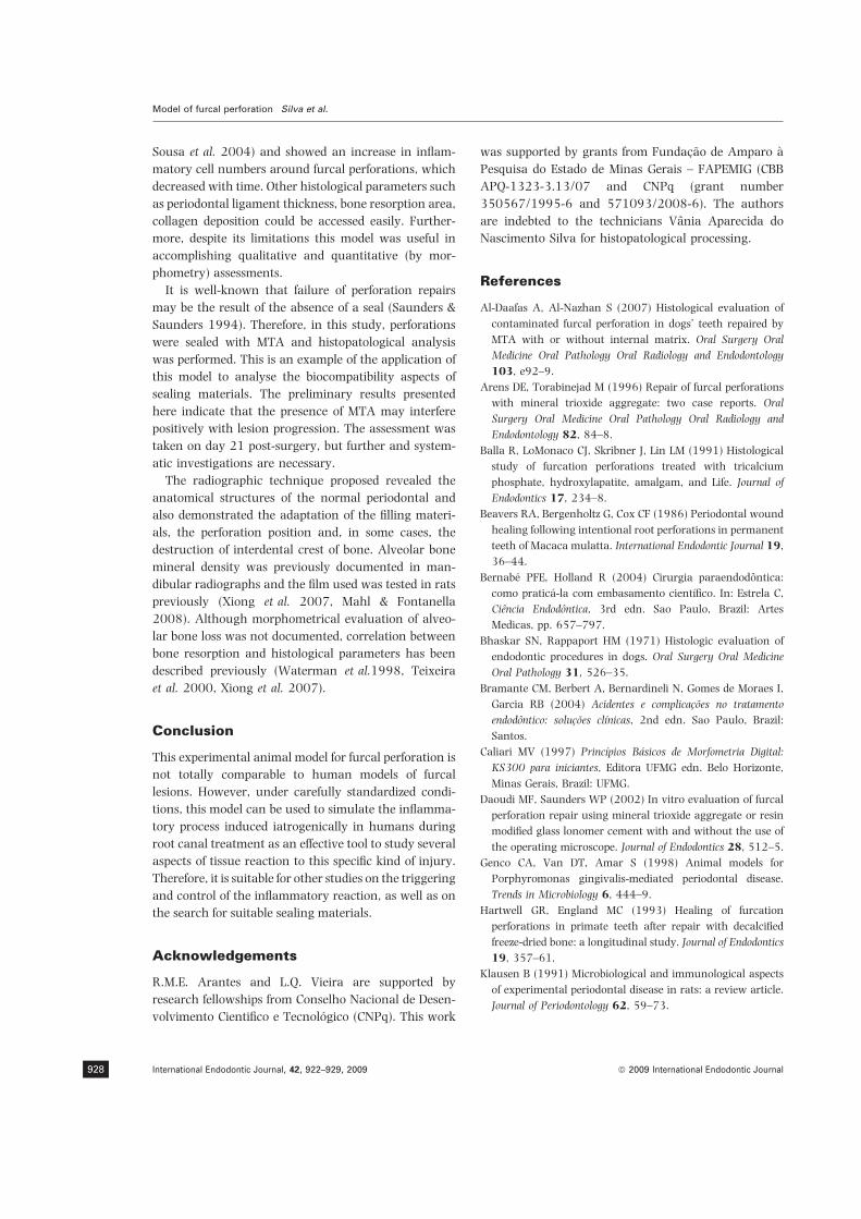
Sousa et al. 2004) and showed an increase in inflam-
matory cell numbers around furcal perforations, which
decreased with time. Other histological parameters such
as periodontal ligament thickness, bone resorption area,
collagen deposition could be accessed easily. Further-
more, despite its limitations this model was useful in
accomplishing qualitative and quantitative (by mor-
phometry) assessments.
It is well-known that failure of perforation repairs
may be the result of the absence of a seal (Saunders &
Saunders 1994). Therefore, in this study, perforations
were sealed with MTA and histopatological analysis
was performed. This is an example of the application of
this model to analyse the biocompatibility aspects of
sealing materials. The preliminary results presented
here indicate that the presence of MTA may interfere
positively with lesion progression. The assessment was
taken on day 21 post-surgery, but further and system-
atic investigations are necessary.
The radiographic technique proposed revealed the
anatomical structures of the normal periodontal and
also demonstrated the adaptation of the filling materi-
als, the perforation position and, in some cases, the
destruction of interdental crest of bone. Alveolar bone
mineral density was previously documented in man-
dibular radiographs and the film used was tested in rats
previously (Xiong et al. 2007, Mahl & Fontanella
2008). Although morphometrical evaluation of alveo-
lar bone loss was not documented, correlation between
bone resorption and histological parameters has been
described previously (Waterman et al.1998, Teixeira
et al. 2000, Xiong et al. 2007).
Conclusion
This experimental animal model for furcal perforation is
not totally comparable to human models of furcal
lesions. However, under carefully standardized condi-
tions, this model can be used to simulate the inflamma-
tory process induced iatrogenically in humans during
root canal treatment as an effective tool to study several
aspects of tissue reaction to this specific kind of injury.
Therefore, it is suitable for other studies on the triggering
and control of the inflammatory reaction, as well as on
the search for suitable sealing materials.
Acknowledgements
R.M.E. Arantes and L.Q. Vieira are supported by
research fellowships from Conselho Nacional de Desen-
volvimento Cientifico e Tecnologico (CNPq). This work
was supported by grants from Fundacao de Amparo a
Pesquisa do Estado de Minas Gerais – FAPEMIG (CBB
APQ-1323-3.13/07 and CNPq (grant number
350567/1995-6 and 571093/2008-6). The authors
are indebted to the technicians Vania Aparecida do
Nascimento Silva for histopatological processing.
References
Al-Daafas A, Al-Nazhan S (2007) Histological evaluation of
contaminated furcal perforation in dogs’ teeth repaired by
MTA with or without internal matrix. Oral Surgery Oral
Medicine Oral Pathology Oral Radiology and Endodontology
103, e92–9.
Arens DE, Torabinejad M (1996) Repair of furcal perforations
with mineral trioxide aggregate: two case reports. Oral
Surgery Oral Medicine Oral Pathology Oral Radiology and
Endodontology 82, 84–8.
Balla R, LoMonaco CJ, Skribner J, Lin LM (1991) Histological
study of furcation perforations treated with tricalcium
phosphate, hydroxylapatite, amalgam, and Life. Journal of
Endodontics 17, 234–8.
Beavers RA, Bergenholtz G, Cox CF (1986) Periodontal wound
healing following intentional root perforations in permanent
teeth of Macaca mulatta. International Endodontic Journal 19,
36–44.
Bernabe PFE, Holland R (2004) Cirurgia paraendodontica:
como pratica-la com embasamento cientıfico. In: Estrela C,
Ciencia Endodontica, 3rd edn. Sao Paulo, Brazil: Artes
Medicas, pp. 657–797.
Bhaskar SN, Rappaport HM (1971) Histologic evaluation of
endodontic procedures in dogs. Oral Surgery Oral Medicine
Oral Pathology 31, 526–35.
Bramante CM, Berbert A, Bernardineli N, Gomes de Moraes I,
Garcia RB (2004) Acidentes e complicacoes no tratamento
endodontico: solucoes clınicas, 2nd edn. Sao Paulo, Brazil:
Santos.
Caliari MV (1997) Princıpios Basicos de Morfometria Digital:
KS300 para iniciantes, Editora UFMG edn. Belo Horizonte,
Minas Gerais, Brazil: UFMG.
Daoudi MF, Saunders WP (2002) In vitro evaluation of furcal
perforation repair using mineral trioxide aggregate or resin
modified glass lonomer cement with and without the use of
the operating microscope. Journal of Endodontics 28, 512–5.
Genco CA, Van DT, Amar S (1998) Animal models for
Porphyromonas gingivalis-mediated periodontal disease.
Trends in Microbiology 6, 444–9.
Hartwell GR, England MC (1993) Healing of furcation
perforations in primate teeth after repair with decalcified
freeze-dried bone: a longitudinal study. Journal of Endodontics
19, 357–61.
Klausen B (1991) Microbiological and immunological aspects
of experimental periodontal disease in rats: a review article.
Journal of Periodontology 62, 59–73.
Model of furcal perforation Silva et al.
International Endodontic Journal, 42, 922–929, 2009 ª 2009 International Endodontic Journal928

Mahl CR, Fontanella V (2008) Optimal parameters for lateral
oblique radiographs of rat mandibles. Dentomaxillofacial
Radiology 37, 224–7.
Meister F, Lommel TJ, Gerstein H, Davies EE (1979) Endodon-
tic perforations which resulted in alveolar bone loss. Report
of five cases. Oral Surgery Oral Medicine Oral Pathology 47,
463–70.
Moller AJR (1966) Microbiological examination of root canals
and periapical tissues of human teeth. Odontol Tidskr 20,
74–5.
Pacheco CMF, Queiroz-Junior CM, Maltos KLM et al. (2008)
Crucial role of peripheral kappa-opioid receptors in a model
of periodontal disease in rats. Journal of Periodontal Research
43, 730–6.
Sampaio P (1967) Placement of a rubber dam on rat molars.
Journal of Dental Research 46, 1102.
Saunders WP, Saunders EM (1994) Coronal leakage as a
cause of failure in root-canal therapy: a review. Endodontics
& Dental Traumatology 10, 105–8.
Seltzer RE, Bender IB (1990) The Dental Pulp, 3rd edn.
Philadelphia: JB Lippincott.
Sousa CJ, Loyola AM, Versiani MA, Biffi JC, Oliveira RP,
Pascon EA (2004) A comparative histological evaluation of
the biocompatibility of materials used in apical surgery.
International Endodontic Journal 37, 738–48.
Teixeira FB, Gomes BP, Ferraz CC, Souza-Filho SC, Zaia AA
(2000) Radiographic analysis of the development of peri-
apical lesions in normal rats, sialoadenectomized rats and
sialoadenectomized-immunosuppressed rats. Dental Trauma-
tology 16, 154–7.
Vajrabhaya LO, Korsuwannawong S, Jantarat J, Korre S
(2006) Biocompatibility of furcal perforation repair material
using cell culture technique: Ketac Molar versus ProRoot
MTA. Oral Surgery Oral Medicine Oral Pathology Oral
Radiology and Endodontology 102, e48–50.
Walton RE, Torabinejad M (2002) Principles and Practice of
Endodontics, 3rd edn. Oxford, UK: W B Saunders Co.
Waterman PA, Torabinejad M, McMillan PJ, Kettering JD
(1998) Development of periradicular lesions in immuno-
suppressed rats. Oral Surgery Oral Medicine Oral Pathology
Oral Radiology and Endodontology 85, 720–5.
Wu MK, van der Sluis LW, Wesselink PR (2005) The risk of
furcal perforation in mandibular molars using Gates-Glidden
drills with anticurvature pressure. Oral Surgery Oral Medi-
cine Oral Pathology Oral Radiology and Endodontology 99,
378–82.
Xiong H, Peng B, Wei L, Zhang X, Wang L (2007) Effect of an
estrogen-deficient state and alendronate therapy on bone
loss resulting from experimental periapical lesions in rats.
Journal of Endodontics 33, 1304–8.
Supporting Information
Additional Supporting Information may be found in the
online version of this article:
Video Clip S1. A video animation was designed
using the blender software (Blender Foundation,
Amsterdam, the Netherlands) to represent the entire
surgical procedure. The video clip is in avi format.
Please note: Wiley-Blackwell are not responsible for
the content or functionality of any supporting materials
supplied by the authors. Any queries (other than
missing material) should be directed to the correspond-
ing author for the article.
Silva et al. Model of furcal perforation
ª 2009 International Endodontic Journal International Endodontic Journal, 42, 922–929, 2009 929

The morphology of the apical foramen in posteriorteeth in a North Indian population
S. Arora & S. TewariDepartment of Operative Dentistry and Endodontics, Government Dental College, Post Graduate Institute of Medical Sciences,
Rohtak, Haryana, India
Abstract
Arora S, Tewari S. The morphology of the apical foramen in
posterior teeth in a North Indian population. International
Endodontic Journal, 42, 930–939, 2009.
Aim To determine the position and shape of the apical
foramina in posterior teeth derived from an Indian
population.
Methodology A total of 800 freshly extracted max-
illary and mandibular premolar and molar teeth from a
native Haryana population were collected. Apices of
teeth were stained with methylene blue and then
examined stereomicroscopically (40·). The following
observations weremade: number of apical foramina; size
and shape of the minor apical foramen; accessory
foramina frequency, and deviation of the minor apical
foramina (frequency and distance) from the apex.
Results The mean maximum and minimum dia-
meter of the minor apical foramina ranged from 0.158
to 0.323 mm. The most common minor apical foramen
shape was oval (81%). Frequency of accessory
foramina was between 2% and 41% for the various
tooth types. The frequency of deviation of the minor
apical foramina from the anatomic apex varied from
43% to 83% and the distance of deviation in all the
teeth was between 0.052 and 2.921 mm.
Conclusions The incidence of oval canals was
higher in this Indian population compared to other
populations. In 92% and 96% of teeth the difference
between the maximum and the minimum diameter of
all foramina was less than or equal to 0.20 and
0.25 mm, respectively. Therefore, four to five instru-
ment sizes larger than the first binding file would have
been necessary to shape the minor apical foramen of
more than 95% of the teeth included in this study to
make them round.
Keywords: anatomical apex, computer-aided stereo-
microscope, major apical foramina, minor apical
foramina.
Received 14 October 2008; accepted 16 April 2009
Introduction
The main objective of root canal treatment is thorough
mechanical and chemical cleansing of the pulp cavity
and its complete filling with an inert material (Kuttler
1958). From the early work of Hess & Zurcher (1925)
to the most recent studies demonstrating anatomic
complexities of the root canal system, it has been
established that a root with a tapering canal and a
single foramen is the exception rather than the rule.
Root canal morphology especially in the apical third is
a critically important factor during conventional root
canal treatment and surgical endodontics.
The apical constriction, when present, is the nar-
rowest part of the root canal, and preparation to this
point should result in a small wound and optimal
healing conditions (Ricucci & Langeland 1998). The
dimension of the apical constriction has been a focus of
debate. The horizontal dimension of the root canal
system is not only more complicated than the vertical
dimension (root canal length or working length) but
also more difficult to investigate. These measurements
could provide clues for the size of master apical file
Correspondence: Dr Sanjay Tewari, Principal and Professor &
Head of Department of Operative Dentistry and Endodontics,
Government Dental College, Post Graduate Institute of Medical
Sciences, Rohtak, Haryana, 124001 India (Tel.: +91 12622
13737; fax: +91 1262213737; e-mail: tewarisanjayrohtak@
yahoo.co.in).
doi:10.1111/j.1365-2591.2009.01597.x
International Endodontic Journal, 42, 930–939, 2009 ª 2009 International Endodontic Journal930

during root canal preparation (Ricucci 1998, Jou et al.
2004) and can have an impact on the selection of the
best instrumentation technique (Cheung et al. 2007).
The clinical philosophy that apical sizes should be
kept as small as possible (Buchanan 2000), rather than
as large as required, disregards the existing scientific
facts. Studies have reported better debridement and
reduced bacterial load with larger apical preparation
(Ram 1977, Chow 1983, Dalton et al. 1998, Siqueira
et al. 1999, Shuping et al. 2000). Dental manufactur-
ers and some individuals are suggesting apical instru-
mentation with rotary instruments of sizes 20, 25 and
30 (Spangberg 2001). However this gives the errone-
ous impression that apical diameters of canals are small
in size; even though the dimensions of the apical
foramina and the apical canal region are reported to be
larger (Morfis et al. 1994, Gani & Visvisian 1999, Wu
et al. 2000, Marroquin et al. 2004).
Wide variations in the dimensions of the apical
constriction have been reported. Cheung et al. (2007)
reported the mean value for the longest and the
shortest diameter of the apical constriction of mesial
and distal canals of C-shaped mandibular second
molars to be 0.26 : 0.15 mm and 0.36 : 0.22 mm,
respectively. Marroquin et al. (2004) reported mean
narrow (0.20 mm) and wide (0.26 mm) diameters of
minor apical foramina in mandibular molars, 0.18–
0.25 mm in the mesio-buccal and distobuccal roots
and 0.22–0.29 mm in the palatal root of the maxillary
molars. Morfis et al. (1994) reported a mean diameter
of 0.26 and 0.39 mm for the mesial and distal canals,
respectively, in mandibular molars (without defining
the exact site of measurement).
Previous studies have frequently demonstrated that
the apical foramen is not always located at the tip of the
root. The frequency of deviation of the major foramen
from the anatomical apex ranged from 46% to 92%
and the mean distance between them ranged from 0.2
to 1.38 mm (Kuttler 1955, Green 1956, 1960, Palmer
et al. 1971, Burch & Hulen 1972, Pineda & Kuttler
1972, Blaskovic-Subat et al. 1992, Morfis et al. 1994,
Marroquin et al. 2004, Cheung et al. 2007). Further-
more, these studies have shown that frequency of
deviation varies in different races. If the foramen
deviates in the buccal/lingual plane, it is difficult to
locate its position using radiographs alone (Schaeffer
et al. 2005). ElAyouti et al. (2001, 2002) also reported
that a seemingly accurate working length ending
radiographically 0–2 mm short of the radiographic
apex can result in overestimation of working length in
51% of the root canals. Therefore, misinterpretation of
dental radiographs may lead to an incorrect determi-
nation of working length and to subsequent complica-
tions of over-instrumentation and overfilling of the root
canal (Seltzer et al. 1971).
The cosmopolitan nature of urban populations
means that endodontists treat an increasing number
of patients of different and mixed racial origin. It is,
therefore, important to be aware of the frequency of
racially determined anatomic variations. A number
of studies have shown different trends in morphology of
roots and canals amongst the different races (Caliskan
et al. 1995, Gulabivala et al. 2001, 2002, Ng et al.
2001, Wasti et al. 2001, Sert & Bayirli 2004, Al-Qudah
& Awawdeh 2006). Additionally, no such morphomet-
ric study has yet been conducted in Indian populations.
In view of conflicting findings regarding the apical
zone and scarce reports on teeth of Indian origin, the
objective of this study was to determine further the
number, shape, diameter of the apical foramina as well
as the incidence of their deviation from the anatomical
apex, the distance between them and the frequency of
accessory foramina in an Indian population.
Materials and methods
A total of 800 freshly extracted human permanent
maxillary and mandibular posterior teeth, with com-
pletely formed apices, obtained from a North Indian
(Haryana) population were included. Teeth were col-
lected from a general district hospital attended by local
population. Ethnicity of the population was further
verified from the outpatient records. Teeth were
extracted because of periodontal or pulpal disease.
Following extraction teeth were washed under tap
water, and stored in 5% sodium hypochlorite (Aroma
Agencies, Mumbai, Maharashtra, India) and used
within 6 months of extraction. The teeth were identi-
fied as maxillary or mandibular first and second
premolars, or first and second molars.
One hundred teeth, with intact crowns (for clear
identification), in each group were selected according to
strict inclusion and exclusion criteria as described by
Marroquin et al. (2004). Primary teeth and roots with
fractures, resorption, or underdevelopment (40·mag-
nification) or that had received any previous endodon-
tic treatment were discarded (Marroquin et al. 2004).
Soft tissues around and in the foramen area were
removed with a size 6 K file (Dentsply Maillefer,
Ballaigues, Switzerland) at 40·magnification. The roots
were then placed in methylene blue (Macsen Labora-
tories, Udaipur, Rajasthan, India), washed under
Arora & Tewari Morphology of apical foramina
ª 2009 International Endodontic Journal International Endodontic Journal, 42, 930–939, 2009 931

running water for 10 min, and dried with pressurized
air before examination.
A computer-aided stereomicroscope with 40·magni-
fication (Stereo zoom microscope RSM-9; Radical Sci-
entific Equipments Pvt. Ltd., Ambala Cantt, Haryana,
India) and VideoTesT-Size 5.0 measurement software
(VideoTesT, St Petersburg, Russia) was used. Measure-
ment accuracy was assured through calibration
between a micro scale with 0.1 mm markings and
the software. The measuring dialogue menu was set in
millimetres and adjusted to three decimal places.
On the external root surface, the opening of the root
canal was called the apical foramen (AF) and its
outermost diameter was termed the ‘major apical
foramen’ (Fig. 1). The minor apical foramen (apical
constriction) was considered to be the region of the
apical foramen with the smallest diameter. From the
minor apical foramen the canal widens as it app-
roaches the major apical foramen (Fig. 1). In clinical
practice, the minor apical foramen is a more consistent
anatomical feature (Ponce & Vilar Fernandez 2003)
and is the preferred landmark for the apical end-point
for root canal treatment. The ‘anatomic apex’ was
defined as the most apical root structure (Fig. 1), and
was traced by marking with red ink. These three
anatomical entities could, theoretically, coincide in
one. A foramen was categorized as accessory when its
diameter was narrower than 0.10 mm (Marroquin
et al. 2004).
After initial confirmation of tooth type, the root
morphology of the apical area was examined under
40·magnification. Teeth were oriented until the major
apical foramen was located in the middle of and parallel
to the objective lens. The image of the minor apical
foramen was then captured by regulating the focus.
Here, minor foramen was that part of the apical
foramen with the smallest planar dimension, as
observed by focusing below the major apical foramen
(Cheung et al. 2007). If a root had more than one
apical foramen, then each foramen was focused sepa-
rately parallel to objective lens by changing the
orientation of tooth and individual photographs were
captured.
The following observations were then made:
1. size of minor apical foramen,
2. shape of minor apical foramen,
3. accessory foramina frequency (if found), and
4. deviation of the minor apical foramen (in mm) from
the apex.
Diameters of the minor apical foramen
The widest and narrowest diameters of each minor
apical foramen were measured using the length mea-
suring mode of the software and defined as the
maximum and the minimum diameters, respectively
(Fig. 2).
Shape of the minor apical foramen
A minor apical foramen with a difference greater than
or equal to 0.02 mm between its maximum and
minimum diameters was considered to have an oval
shape. This criterion was established according to
Marroquin et al. (2004) in consideration of the ISO
tolerances for root canal instruments. The shape of the
minor apical foramen was accordingly determined to
Figure 1 Diagrammatic representations of the morphological
features investigated.
Figure 2 Two minor apical foramina and one accessory
foramen (top most) at apex, measurement of maximum and
minimum diameters of each foramen has been made.
Morphology of apical foramina Arora & Tewari
International Endodontic Journal, 42, 930–939, 2009 ª 2009 International Endodontic Journal932

have either a round, oval, or irregular (triangular,
kidney, or irregular) form.
Frequency and distance of deviation of minor apical
foramen from anatomical apex
If the minor apical foramen was not located at the
anatomical root apex, but at a more cervical position
on the long axis of the root, a straight line parallel to
the root from the most apical point of the foramen to a
tangent line at the most apical point of the anatomical
apex was used to determine the distance between the
minor apical foramen and anatomical apex (Marroquin
et al. 2004) (Fig. 3).
The statistical data were arranged by means, max-
imum, minimum and SD.
Results
A total of 2004 foramina were investigated. The
distance between the minor apical foramen and ana-
tomical apex; frequency of accessory foramina; num-
ber, shape and diameter of apical foramina in each root
of maxillary and mandibular premolars and first and
second premolars are shown in Tables 1–5. In tables
S1–S14 (supporting information) the mean values for
minimum and maximum diameters and distance of
deviation are reported separately for each root with
one, two, three, four, and five foramina. In tables S15–
S16 minimum and maximum diameters of accessory
foramina have been reported.
Number of apical foramina
Mandibular teeth
The number of apical foramina in all posterior teeth is
described in Table 1. In the mandibular posterior teeth
the incidence of a single apical foramen ranged from
64% to 81% except in the mesial root of mandibular
first molars (33%). As many as five apical foramina
were observed in 1% teeth in mandibular first and
second premolars and mesial roots of first molars. The
greatest variation from a single apical foramina was
observed in the mesial roots of mandibular first molars
with an incidence of two, three, four, five foramina in
46%, 16%, 4% and 1%, respectively.
Maxillary teeth
In maxillary teeth the greatest variations from a single
apical foramina were observed in both first and second
premolars followed by the mesiobuccal root of first
molars. The incidence of two foramina was 57%, 38%
and 37% andmore than two foramina in 17%, 21% and
9% of teeth, respectively. In maxillary teeth five apical
Figure 3 Method for measuring distances between the minor apical foramen and the anatomic apex. Each foramen was separately
focused parallel to the objective lens and measurements were made on different photographs. AA denotes anatomic apex, traced by
marking with red ink.
Arora & Tewari Morphology of apical foramina
ª 2009 International Endodontic Journal International Endodontic Journal, 42, 930–939, 2009 933

foramina were found in maxillary second premolars
only, with an incidence of 3% (Fig. 4). Distobuccal roots
of first and second molars showed simpler anatomy
having a maximum two apical foramina only, and no
main apical foramina in 1% teeth.
Frequency of accessory foramen
There was a higher frequency of accessory foramina in
maxillary premolars followed by mandibular premolars
(Table 2). The highest frequency of accessory foramina
was in maxillary second premolars (41%). Values as
low as 2%, for palatal roots of maxillary second molars
were also obtained.
Deviation of minor apical foramina from the
anatomical apex
Deviation of the minor apical foramina from the
anatomical apex was seen in all teeth but there was
no conclusive pattern of variation (Table 3). Frequency
of deviation of minor apical foramina (Table 3) from
the apex varied from 43% in maxillary first premolars
to 83% in mandibular first premolars.
The highest mean value of the distance between the
minor apical foramen and the anatomical apex was
observed in the mesiobuccal root of maxillary first
molars (0.996 mm). The lowest value of 0.632 mm
was observed for the distobuccal root of maxillary
second molars (Table 3).
Diameters of minor apical foramina
The mean maximum diameter (Table 4) of the minor
apical foramina ranged from 0.230 mm (distobuccal
root of maxillary second molars) to 0.323 mm (distal
root of mandibular second molars). The mean mini-
mum diameter (Table 5) of the minor apical foramina
ranged from 0.158 mm (mandibular second premo-
lars) to 0.227 mm (distal root of mandibular second
molars).
Discussion
A digital stereomicroscope with integrated software
was used to provide accurate measurement of a large
number of teeth. Teeth were oriented until the apical
foramen was located in the middle of and parallel to the
objective lens to allow measurement of the true
dimensions of the minor apical foramen irrespective
of the curvature that a canal follows inside the root.
If the apical foramen was located at a more cervical
position on the long axis of the root, a straight line
parallel to the root from the most apical point of the
foramen to a tangent line at the most apical point of the
anatomical apex was drawn for each foramina. This
determined the true distance not the vertical distance
between the apical foramen and anatomical apex.
However this distance can not be measured in vivo
because of limitations of radiographs in identifying
accurately the foramina on buccal/lingual root surfaces
Table 1 Number of apical foramina by tooth type
Single Two Three Four Five
Mandibular teeth
Mandibular first premolar 70 24 3 2 1
Mandibular second premolar 74 16 6 3 1
Mandibular first molar
Mesial root 33 46 16 4 1
Distal root 75 22 2 1 X
Mandibular second molar
Mesial root 64 33 3 X X
Distal root 81 18 X 1 X
Maxillary teeth
Maxillary first premolar 25 57 13 4 X
Maxillary second premolar 41 38 16 2 3
Maxillary first molar
Mesiobuccal root 54 37 6 3 X
Distobuccal root 91 8 X X X
Palatal root 78 20 2 X X
Maxillary second molar
Mesiobuccal root 61 31 5 3 X
Distobuccal root 80 13 X X X
Palatal root 88 11 1 X X
Table 2 Frequency of accessory foramina by tooth type
0 1 2 3 4 5 Total
Mandibular teeth
Mandibular first premolar 91 7 2 X X X 11
Mandibular second premolar 91 6 0 1 2 X 17
Mandibular first molar
Mesial root 86 13 1 X X X 15
Distal root 96 4 X X X X 4
Mandibular second molar
Mesial root 95 5 X X X X 5
Distal root 94 6 X X X X 6
Maxillary teeth
Maxillary first premolar 87 8 1 3 X 1 24
Maxillary second premolar 72 12 3 3 1 2 41
Maxillary first molar
Mesiobuccal root 92 5 2 1 X X 12
Distobuccal root 95 5 X X X X 5
Palatal root 93 5 2 X X X 9
Maxillary second molar
Mesiobuccal root 86 7 5 X 2 X 25
Distobuccal root 96 4 X X X X 4
Palatal root 98 2 X X X X 2
Morphology of apical foramina Arora & Tewari
International Endodontic Journal, 42, 930–939, 2009 ª 2009 International Endodontic Journal934

(Schaeffer et al. 2005), as well as the inability of the
electronic apex locators in locating the canal terminus
with 100% accuracy (Wrbas et al. 2007, ElAyouti et al.
2009).
The frequency of deviation of the minor apical
foramen from the apex (43–83%), distances of the
minor apical foramina from the apex (0.052–
2.921 mm) and mean distance of minor apical foram-
ina from anatomic apex reported in the present study
(0.632–0.996 mm) compare with the literature
(Kuttler 1955, Green 1956, 1960, Palmer et al.
1971, Pineda & Kuttler 1972, Vertucci 1984, Blask-
ovic-Subat et al. 1992, Morfis et al.1994, Marroquin
et al. 2004). The minor differences observed between
various studies may be explained by the different
measuring methods, by the different apical foramen
definitions used and by difference in reference points to
measure the distances. These results demonstrate the
complexity of the apical zone in this Indian population
and the similarity with other parts of the world. Thus,
they suggest that the endodontic principles and prac-
tices being followed in the other parts of the world can
also be applied to this Indian population. The unpre-
dictable nature of the position of the apical constriction
with respect to the radiographic apex further strength-
ens the need of using apex locators rather than relying
on radiographs for canal length determination. These
findings also support the current practice of cutting
3 mm of the root apex (Kim & Kratchman 2006)
during surgical procedures to ensure the removal of
most of the unprepared and unfilled canals.
Unlike most of the previous studies mesial and
mesiobuccal roots of mandibular and maxillary molars
respectively had a higher frequency of single foramen.
This may be interpreted that there was a high tendency
for Type II (two canals merging into one at apex) canals
Table 3 Distance (in mm) and %age
deviation of minor apical foramina from
the apex by tooth type
Minimum Maximum Average SD %Deviation
Mandibular teeth
First premolar 0.112 2.186 0.796 0.415 83
Second premolar 0.052 2.892 0.781 0.463 78
First molar: mesial root 0.154 2.808 0.834 0.496 50
First molar: distal root 0.167 1.617 0.817 0.297 68
Second molar: mesial root 0.127 2.202 0.78 0.465 46
Second molar: distal root 0.065 2.031 0.809 0.322 44
Maxillary teeth
First premolar 0.18 2.03 0.78 0.391 43
Second premolar 0.122 2.523 0.984 0.407 49
First molar: mesiobuccal root 0.176 2.921 0.996 0.676 59
First molar: distobuccal root 0.225 2.224 0.824 0.441 54
First molar: palatal root 0.26 2.455 0.924 0.466 68
Second molar: mesiobuccal root 0.276 2.527 0.992 0.580 59
Second molar: distobuccal root 0.106 1.433 0.632 0.319 49
Second molar: palatal root 0.122 0.873 0.719 0.313 61
Table 4 Maximum diameter (in mm) of
minor apical foramina by tooth typeMinimum Maximum Average SD
Mandibular teeth
First premolar 0.1 1.169 0.256 0.122
Second premolar 0.104 1.45 0.241 0.144
First molar: mesial root 0.102 1.265 0.261 0.153
First molar: distal root 0.116 0.585 0.300 0.104
Second molar: mesial root 0.112 0.793 0.303 0.143
Second molar: distal root 0.122 1.168 0.323 0.142
Maxillary teeth
First premolar 0.106 0.553 0.24 0.092
Second premolar 0.103 1.394 0.254 0.139
First molar: mesiobuccal root 0.1 0.835 0.263 0.125
First molar: distobuccal root 0.103 0.524 0.257 0.082
First molar: palatal root 0.108 0.794 0.320 0.146
Second molar: mesiobuccal root 0.105 0.509 0.244 0.098
Second molar: distobuccal root 0.103 0.43 0.230 0.078
Second molar: palatal root 0.117 0.794 0.309 0.12
Arora & Tewari Morphology of apical foramina
ª 2009 International Endodontic Journal International Endodontic Journal, 42, 930–939, 2009 935
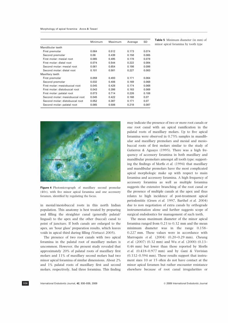
in mesial/mesiobuccal roots in this north Indian
population. This anatomy is best treated by preparing
and filling the straighter canal (generally palatal/
lingual) to the apex and the other (buccal) canal to
point of juncture. If both canals are enlarged to the
apex, an ‘hour glass’ preparation results, which leaves
voids in apical third during filling (Vertucci 2005).
The presence of two root canals with two apical
foramina in the palatal root of maxillary molars is
uncommon. However, the present study revealed that
approximately 20% of palatal roots of maxillary first
molars and 11% of maxillary second molars had two
minor apical foramina of similar dimensions. About 2%
and 1% palatal roots of maxillary first and second
molars, respectively, had three foramina. This finding
may indicate the presence of two or more root canals or
one root canal with an apical ramification in the
palatal roots of maxillary molars. Up to five apical
foramina were observed in 0.75% samples in mandib-
ular and maxillary premolars and mesial and mesio-
buccal roots of first molars similar to the study of
Gutierrez & Aguayo (1995). There was a high fre-
quency of accessory foramina in both maxillary and
mandibular premolars amongst all tooth type; support-
ing the findings of Morfis et al. (1994) that maxillary
and mandibular premolars have the most complicated
apical morphologic make up with respect to main
foramina and accessory foramina. A high frequency of
accessory foramina as well as multiple foramina
suggests the extensive branching of the root canal or
the presence of multiple canals at the apex and thus
relates to high incidence of post-treatment apical
periodontitis (Green et al. 1997, Barthel et al. 2004)
due to non negotiation of extra canals by orthograde
instrumentation alone and further suggests scope of
surgical endodontics for management of such teeth.
The mean maximum diameter of the minor apical
foramina ranged from 0.23 to 0.32 mm and the mean
minimum diameter was in the range 0.158–
0.227 mm. These values were in accordance with
Marroquin et al. (2004) (0.20–0.29 mm), Cheung
et al. (2007) (0.32 mm) and Wu et al. (2000) (0.13–
0.46 mm) but lower than those reported by Morfis
et al. (0.418–0.977 mm) and by Gani & Visvisian
(0.332–0.594 mm). These results support that instru-
ment sizes 10 or 15 often do not have contact at the
minor apical foramen but rather encounter resistance
elsewhere because of root canal irregularities or
Table 5 Minimum diameter (in mm) of
minor apical foramina by tooth typeMinimum Maximum Average SD
Mandibular teeth
First premolar 0.064 0.512 0.173 0.074
Second premolar 0.06 0.439 0.158 0.065
First molar: mesial root 0.065 0.495 0.178 0.078
First molar: distal root 0.074 0.544 0.222 0.084
Second molar: mesial root 0.061 0.654 0.198 0.098
Second molar: distal root 0.101 0.581 0.227 0.083
Maxillary teeth
First premolar 0.059 0.493 0.171 0.064
Second premolar 0.032 0.406 0.169 0.068
First molar: mesiobuccal root 0.045 0.428 0.174 0.068
First molar: distobuccal root 0.043 0.398 0.183 0.069
First molar: palatal root 0.073 0.714 0.226 0.108
Second molar: mesiobuccal root 0.045 0.422 0.168 0.07
Second molar: distobuccal root 0.052 0.387 0.171 0.07
Second molar: palatal root 0.065 0.506 0.218 0.087
Figure 4 Photomicrograph of maxillary second premolar
(40·), with five minor apical foramina and one accessory
foramen, identified by regulating the focus.
Morphology of apical foramina Arora & Tewari
International Endodontic Journal, 42, 930–939, 2009 ª 2009 International Endodontic Journal936

curvature. So, in this Indian population the first file
that will truly bind at the apex, i.e. initial working
width at working length would correspond to at least a
size 20 file.
The most common shape of the minor apical
foramen was oval. The frequencies were between
79% and 89% for various roots. This prevalence of
oval canals were higher than Marroquin et al. (2004)
and Wu et al. (2000) and lower than Gani & Visvisian
(1999). Other forms of apical foramina such as
triangular, kidney, or irregular forms were observed
in 0.5% of the roots (Fig. 5).
One of the major point of interest when planning this
investigation was its clinical significance when shaping
and cleaning the root canal of this Indian population.
The determination of the first file that binds in the
apical part of the root canal does not allow a reliable
prediction of the appropriate final instrument size
required for complete apical enlargement. The final
instrument size must be large enough to touch all
walls. Because most canals are oval in their cross
sectional shape, the goal should be to make the final
apical instrument size correspond to the largest diam-
eter of the oval to make these canals round. The
difference between the wide and narrow diameters of
the apical constriction region in mandibular premolars
in this population, was less than or equal to 0.15 mm
in 86% teeth therefore enlarging up to three instru-
ment sizes larger than the first binding file in apical
constriction region (FAB) will shape the minor apical
foramen area round only in 86% teeth. This difference
between the wide and narrow diameters in these
premolars was less than or equal to 0.20 mm in 91%
and less than or equal to 0.25 mm in 97% teeth so
shaping up to 4 instrument sizes larger than FAB will
shape apical area in 91% and five instrument size
larger than FAB will shape the apical area in 97% teeth
to a round outline. Similarly, for the rest of the teeth it
was found that up to three instrument sizes larger than
FAB would shape the apical constriction round in only
84% of mandibular molars, 88% of maxillary premo-
lars and 87% of maxillary molars. While four instru-
ment sizes larger than FAB will shape apical
constriction round in 89% of mandibular molars,
93% of maxillary premolars and 94% of maxillary
molars, and five instrument sizes larger than the FAB
will shape apical constriction round in 94% of man-
dibular molars, 97% of maxillary premolars and 96% of
maxillary molars. These findings suggest that in the
absence of any predictable method to measure accurate
working width, enlargement of apical third 4–5 sizes
larger than first file to bind at the apex may ensure
complete involvement of the largest diameter of an oval
canal in more than 95% teeth and will produce a round
shape of apical preparation for proper filling with a
round gutta percha cone.
Conclusions
The incidence of oval canals was higher in this Indian
population (81%) compared to other populations and
occurred in 79–88% of roots depending on tooth type.
In 92% and 96% of teeth the difference between the
maximum and the minimum diameter of all foramina
was less than or equal to 0.20 and 0.25 mm, respec-
tively, therefore four to five instrument sizes larger than
the first binding file would have been necessary to
shape the minor apical foramen of more than 95% of
the teeth included in this study to make them round.
References
Al-Qudah AA, Awawdeh LA (2006) Root canal morphology of
mandibular incisors in a Jordanian population. International
Endodontic Journal 39, 873–7.
Barthel CR, Zimmer S, Trope M (2004) Relationship of
radiologic and histologic signs of inflammation in human
root-filled teeth. Journal of Endodontics 30, 75–9.
Blaskovic-Subat V, Maricic B, Sutalo J (1992) Asymmetry of
the root canal foramen. International Endodontic Journal 25,
158–64.
Buchanan LS (2000) The standardized-taper root canal
preparation – Part 1. Concepts for variably tapered
shaping instruments. International Endodontic Journal 33,
516–29.
Figure 5 Minor apical foramina of various irregular shapes
(irregular, kidney shaped, triangular).
Arora & Tewari Morphology of apical foramina
ª 2009 International Endodontic Journal International Endodontic Journal, 42, 930–939, 2009 937

Burch JG, Hulen S (1972) The relationship of the apical
foramen to the anatomic apex of the tooth root. Oral
Surgery, Oral Medicine and Oral Pathology 34, 262–8.
Caliskan MK, Pehlivan Y, Sepetcioglu F, Turkun M, Tuncer
SS (1995) Root canal morphology of human permanent
teeth in a Turkish population. Journal of Endodontics 21,
200–4.
Cheung GSP, Yang J, Fan B (2007) Morphometric study of the
apical anatomy of C-shaped root canal systems in mandib-
ular second molars. International Endodontic Journal 40,
239–46.
Chow T (1983) Mechanical effectiveness of root canal irriga-
tion. Journal of Endodontics 9, 475–9.
Dalton BC, Orstavik D, Phillips C, Pettiette M, Trope M (1998)
Bacterial reduction with nickel–titanium rotary instrumen-
tation. Journal of Endodontics 24, 763–7.
ElAyouti A, Weiger R, Lost C (2001) Frequency of overin-
strumentation with an acceptable radiographic working
length. Journal of Endodontics 27, 49–52.
ElAyouti A, Weiger R, Lost C (2002) The ability of root ZX
apex locator to reduce the frequency of overestimated
radiographic working length. Journal of Endodontics 28,
116–9.
ElAyouti A, Dima E, Ohmer J, Sperl K, von Ohle C, Lost C
(2009) Consistency of apex locator function. Journal of
Endodontics 35, 179–81.
Gani O, Visvisian C (1999) Apical canal diameter in the first
upper molar at various ages. Journal of Endodontics 25, 689–
91.
Green D (1956) A stereomicroscopic study of the root apices of
400 maxillary and mandibular teeth. Oral Surgery, Oral
Medicine and Oral Pathology 9, 1224–32.
Green D (1960) Stereomicroscopic study of 700 root apices of
maxillary and mandibular posterior teeth. Oral Surgery, Oral
Medicine and Oral Pathology 13, 728–33.
Green TL, Walton RE, Taylor JK, Merrell P (1997) Radio-
graphic and histologic periapical findings of root canal
treated teeth in cadaver. Oral Surgery, Oral Medicine, Oral
Pathology, Oral Radiology, and Endodontics 83, 707–11.
Gulabivala K, Aung TH, Alavi A, Ng YL (2001) Root and
canal morphology of Burmese mandibular molars. Interna-
tional Endodontic Journal 34, 359–70.
Gulabivala K, Opasanon A, Ng YL, Alavi A (2002) Root canal
morphology of Thai mandibular molars. International End-
odontic Journal 35, 56–62.
Gutierrez JH, Aguayo P (1995) Apical foraminal openings in
human teeth. Number and location. Oral Surgery, Oral
Medicine, Oral Pathology, Oral Radiology, and Endodontics 79,
769–77.
Hess W, Zurcher E (1925) The Anatomy of Root Canals of the
Teeth of the Permanent and Deciduous Dentitions. New York:
William Wood & Co.
Jou YT, Karabucak B, Levin J, Liu D (2004) Endodontic
working width: current concepts and techniques. Dental
Clinics of North America 48, 323–35.
Kim S, Kratchman S (2006) Modern endodontic surgery
concepts and practice: a review. Journal of Endodontics 32,
601–23.
Kuttler Y (1955) Microscopic investigation of root apexes.
Journal of the American Dental Association 50, 544–52.
Kuttler Y (1958) A Precision and Biologic root canal filling
technic. Journal of the American Dental Association 56, 38–
50.
Marroquin BB, El-SayedMA,Wilershausen-Zonnchen B (2004)
Morphology of the physiological foramen. I. Maxillary and
mandibular molars. Journal of Endodontics 30, 321–8.
Morfis A, Sylaras SN, Georgopoulou M, Kernani M, Prountzos
F (1994) Study of the apices of human permanent teeth
with the use of a scanning electron microscope. Oral
Surgery, Oral Medicine and Oral Pathology 77, 172–6.
Ng YL, Aung TH, Alavi A, Gulabivala K (2001) Root and
canal morphology of Burmese maxillary molars. Interna-
tional Endodontic Journal 34, 620–30.
Palmer MJ, Weine FS, Healey H (1971) Position of the apical
foramen in relation to endodontic therapy. Journal of the
Canadian Dental Association 37, 305–8.
Pineda F, Kuttler Y (1972) Mesiodistal and buccolingual
roentgenographic investigation of 7,275 root canals. Oral
Surgery, Oral Medicine and Oral Pathology 33, 101–10.
Ponce EH, Vilar Fernandez JA (2003) The cemento-dentino-
canal junction, the apical foramen, and the apical constric-
tion: evaluation by optical microscopy. Journal of Endodontics
29, 214–9.
Ram Z (1977) Effectiveness of root canal irrigation. Oral
Surgery, Oral Medicine and Oral Pathology 44, 306–12.
Ricucci D (1998) Apical limit of root canal instrumentation
and obturation. Part 1. Literature review. International
Endodontic Journal 31, 384–93.
Ricucci D, Langeland K (1998) Apical limit of root canal
instrumentation and obturation. Part 2. A histological
study. International Endodontic Journal 31, 394–409.
Schaeffer M, White R, Walton R (2005) Determining the
optimal obturation length: a meta-analysis of the literature.
Journal of Endodontics 31, 271–4.
Seltzer S, Soltanoff W, Sinai I (1971) Biologic aspects of
endodontics. III. Periapical tissue reactions to root canal
instrumentation. Oral Surgery, Oral Medicine and Oral
Pathology 33, 101–10.
Sert S, Bayirli GS (2004) Evaluation of the root canal
configurations of the mandibular and maxillary permanent
teeth by gender in the Turkish population. Journal of
Endodontics 30, 391–8.
Shuping G, Orstavik D, Sigurdsson A, Trope M (2000)
Reduction of intracanal bacteria using nickel-titanium
rotary instrumentation and various medications. Journal of
Endodontics 26, 751–5.
Siqueira J, Lima K, Magalhaes F, Lopes H, de Uzeda M (1999)
Mechanical reduction of the bacterial population in the root
canal by three instrumentation techniques. Journal of
Endodontics 25, 332–5.
Morphology of apical foramina Arora & Tewari
International Endodontic Journal, 42, 930–939, 2009 ª 2009 International Endodontic Journal938

Spangberg L (2001) The wonderful world of rotary root canal
preparation. Oral Surgery, Oral Medicine, Oral Pathology, Oral
Radiology and Endodontics 92, 479.
Vertucci FJ (1984) Root canal anatomy of the human
permanent teeth. Oral Surgery, Oral Medicine and Oral
Pathology 58, 589–99.
Vertucci FJ (2005) Root canal morphology and its relationship
to endodontic procedures. Endodontic Topics 10, 3–29.
Wasti F, Shearer AC, Wilson NH (2001) Root canal systems of
the mandibular and maxillary first permanent molar teeth
of south Asian Pakistanis. International Endodontic Journal
34, 263–6.
Wrbas KT, Ziegler AA, Altenburger MJ, Schirrmeister JF
(2007) In vivo comparison of working length determination
with two electronic apex locators. International Endodontic
Journal 40, 133–8.
Wu M-K, Roris A, Barkis D, Wesselink PR (2000) Prevalence
and extent of long oval canals in the apical third. Oral
Surgery, Oral Medicine, Oral Pathology, Oral Radiology and
Endodontics 89, 739–43.
Supporting Information
Additional Supporting Information may be found in the
online version of this article:
Table S1. Mandibular First Premolar.
Table S2. Mandibular Second Premolar.
Table S3. Mandibular First Molar Mesial Root.
Table S4. Mandibular First Molar Distal Root.
Table S5. Mandibular Second Molar Mesial Root.
Table S6. Mandibular Second Molar Distal Root.
Table S7. Maxillary First Premolar.
Table S8. Maxillary Second Premolar.
Table S9. Maxillary First Molar (Mesiobuccal Root).
Table S10. Maxillary First Molar (Distobuccal Root).
Table S11. Maxillary First Molar (Palatal Root).
Table S12. Maxillary Second Molar (Mesiobuccal
Root).
Table S13. Maxillary Second Molar ( Distobuccal
Root).
Table S14. Maxillary Second Molar (Palatal Root).
Table S15.Maximum diameter (in mm) of accessory
foramina by tooth type.
Table S16. Minimum diameter (in mm) of accessory
foramina by tooth type.
Please note: Wiley-Blackwell are not responsible for
the content or functionality of any supporting materials
supplied by the authors. Any queries (other than
missing material) should be directed to the correspond-
ing author for the article.
Arora & Tewari Morphology of apical foramina
ª 2009 International Endodontic Journal International Endodontic Journal, 42, 930–939, 2009 939

Carbon dioxide laser irradiation stimulatesmineralization in rat dental pulp cells
Y. Yasuda1, E. Ohtomo1, T. Tsukuba2, K. Okamoto2 & T. Saito1
1Division of Clinical Cariology and Endodontology, Department of Oral Rehabilitation, School of Dentistry, Health Sciences
University of Hokkaido, Hokkaido, Japan; and 2Division of Oral Pathopharmacology, Department of Medical and Dental Sciences,
Nagasaki University Graduate School of Biomedical Sciences, Nagasaki, Japan
Abstract
Yasuda Y, Ohtomo E, Tsukuba T, Okamoto K, Saito T.
Carbon dioxide laser irradiation stimulates mineralization in rat
dental pulp cells. International Endodontic Journal, 42, 940–946,
2009.
Aim To examine the effect of carbon dioxide laser
irradiation on mineralization in dental pulp cells.
Methodology Rat dental pulp cells were irradiated
with a carbon dioxide laser at 2 W output power for
20, 40 and 60 s, and were cultured in ascorbic acid
and b-glycerophosphate containing media. Cell viabil-
ity was examined 24 h after laser irradiation by a
modified MTT assay. Alizarin Red S staining was
performed 10 days after laser irradiation. The amounts
of secreted collagen from the cells after irradiation were
quantified following Sirius Red staining. The expression
levels of collagen type I and HSP47, collagen-binding
stress protein, were analysed by real-time PCR. HSP47
protein expression was examined by Western blotting.
Statistical analysis was performed using one-way
analysis of variance (anova) followed by the Tukey’s
multiple comparison test.
Results The cell viability was not affected by laser
irradiation at 2 W for up to 40 s. However, it was
significantly decreased by 20% at 60 s (P < 0.05). The
amount of mineralization after 10 days of irradiation at
2 W for 40 s was significantly increased in comparison
to the other conditions (P < 0.05). The extracellular
collagen production was significantly increased by 73%
on day 2 and 38% on day 4 after laser irradiation
(P < 0.05). Although collagen type I gene expression
was not changed by laser irradiation, HSP47 gene and
protein expression was induced within 12 and 24 h,
respectively.
Conclusions These results suggested that carbon
dioxide laser irradiation stimulated mineralization in
dental pulp cells. The laser irradiation also increased
HSP47 expression but not collagen gene expression.
Keywords: carbon dioxide laser, collagen, dental
pulp cells, heat shock protein 47, mineralization.
Received 28 December 2007; accepted 16 April 2009
Introduction
Reparative dentine forms in the dental pulp in response
to various external stimuli such as caries and abrasion
(Kamal et al. 1997, Lee et al. 2006). Direct pulp
capping with calcium hydroxide has been advocated
to accelerate reparative dentine formation on the
exposed pulp surface. However, calcium hydroxide is
highly alkaline and causes an inflammatory response.
In addition, it has not always been clinically highly
efficacious in the uniform formation of reparative
dentine (Scarano et al. 2003). Recently, the use of
mineral trioxide aggregate (MTA) in direct pulp
capping has been reported (Aeinehchi et al. 2003,
Chacko & Kurikose 2006). MTA is superior to calcium
hydroxide for pulp capping of mechanically exposed
human teeth; however, a variety of histological
responses were still observed (Caicedo et al. 2006).
Furthermore, no data from long-term clinical results
Correspondence: Yoshiyuki Yasuda, DDS, PhD, Division of
Clinical Cariology and Endodontology, Department of Oral
Rehabilitation, School of Dentistry, Health Sciences University
of Hokkaido, 1757 Kanazawa, Ishikari-Tobetsu, Hokkaido
061-0293, Japan (Tel.: +81 133 23 2841; fax: +81 133 23
1423, e-mail: [email protected]).
doi:10.1111/j.1365-2591.2009.01598.x
International Endodontic Journal, 42, 940–946, 2009 ª 2009 International Endodontic Journal940

are yet available. In an ideal situation, the exposed pulp
surface should be covered promptly with reparative
dentine and the dental pulp should not demonstrate an
inflammatory response.
The application of lasers has expanded into various
fields and has also been frequently used in clinical
dentistry (Pearson & Schuckert 2003, Parker 2007). In
cultured cells, irradiation by low power laser, such as a
diode laser, has been reported to accelerate cell
differentiation and mineralization in calvarial and
dental pulp cells (Ozawa et al. 1998, Ohbayashi et al.
1999, Ueda & Shimizu 2003). On the other hand,
Moritz et al. (1998a,b) reported that the utility of a
high power laser, such as a carbon dioxide laser, is
useful on exposed pulp surfaces in direct pulp cap-
ping experiments. Furthermore, Melcer et al. (1987)
observed that a neo-dentine bridge was formed in the
pulp tissue after carbon dioxide laser irradiation on
teeth, suggesting that this laser is effective in mineral-
ization. However, the mechanism by which carbon
dioxide laser irradiation stimulates mineralization in
direct pulp capping treatment is not fully elucidated.
Laser irradiation may affect the collagen production in
dental pulp cells, because the collagenous network
plays an important role in mineralization (Linde 1989).
Heat shock proteins (HSPs) are induced by stress
from heat and chemical stimuli (Noda et al. 2002).
HSPs have been known to suppress the aggregation of
denatured protein (Guzhova & Margulis 2006). They
are also constitutively expressed in normal cells, and
are associated with important functions such as protein
synthesis and intracellular transport (Eisenberg &
Greene 2007). In particular, HSP47 is a collagen-
specific molecular chaperone. It specifically binds to
collagen and plays an essential role in collagen
production (Masuda et al. 1994, Koide et al. 2002).
The purpose of this study was to examine the effect of
a carbon dioxide laser on mineralization in rat dental
pulp cells. Moreover, the amount of extracellular
secreted collagen and the HSP47 expression levels
were examined to clarify the stimulatory effects of
carbon dioxide laser irradiation on mineralization of
dental pulp cells.
Materials and methods
Cells and cell culture conditions
All animal protocols were approved by the Institutional
Animal Care and Use Committee of the Health Sciences
University of Hokkaido, and experiments were carried
out under the control of the University’s Guidelines for
Animal Experimentation. The dental pulp cells were
isolated from incisors of Wistar rats (female, 5-week-
old) as described previously (Yokose et al. 2000). The
cells were cultured in Dulbecco’s modified eagle
medium (DMEM; Sigma, St Louis, MI, USA) supple-
mented with 10% foetal bovine serum (Sigma),
10 000 U mL)1 penicillin (Invitrogen, Grand Island,
NY, USA), and 10 mg mL)1 streptomycin (Invitrogen)
at 37 �C in a humidified atmosphere of 5% carbon
dioxide.
Laser irradiation
A carbon dioxide laser apparatus (Bel Luxar LX-20SP,
Takara, Kyoto, Japan) with a wavelength of 10.6 lmand a power output of 2.0 W (A4 mode, 10 pps,
average power output of 0.3 W) was used. Rat dental
pulp cells (5 · 104 cells per well) were seeded out in
24-well plates and cultured for 24 h, and then serum-
starved for 24 h. After withdrawal of medium, the cells
were irradiated at 2 W output power for 20, 40 and
60 s using the scanning method as applied in clinical
laser irradiation. The tip was moved gradually at a
constant rate, avoiding concentrating laser light on one
site, and the whole area was irradiated. The laser beam
was delivered by a ceramic tip (0.8 mm diameter) with
the distance from the tip of the fibre to the cell layer
being 2 cm (irradiation diameter approximately
2 mm). The total energy of irradiation time of 40 s
was 382.2 J cm)2. Irradiated or nonirradiated (control)
cells were cultured in DMEM containing 50 lg mol L)1
ascorbic acid (AA, Sigma) and 10 m mL)1 b-glycero-phosphate (b-GP, Sigma) for 10 days.
Cell viability assay
Rat dental pulp cells were cultured in DMEM contain-
ing 50 lg mL)1 AA and 10 mmol L)1 b-GP for 24 h
after irradiation or nonirradiation (control). Cell viabil-
ity was determined by a modified MTT assay (WST-8
assay: Dojindo, Kumamoto, Japan), and data are
presented as a percentage of viability values seen under
control culture conditions. The assay is based on the
cleavage of tetrazolium salt WST-8 to formazan by
cellular mitochondrial dehydrogenase. The amount of
the dye generated by activity of dehydrogenase is
directly proportional to the number of living cells. For
the WST-8 assay, a 10-lL quantity of WST-8 dye
solution was added directly to 100 lL of culture
medium per well. The absorbance of the dye was
Yasuda et al. Effect of laser irradiation
ª 2009 International Endodontic Journal International Endodontic Journal, 42, 940–946, 2009 941

measured at 450 nm using a Model 680 microplate
reader (Bio-Rad, Hercules, CA, USA).
Quantitative Alizarin Red S staining
Rat dental pulp cells were cultured as before in
50 lg mL)1 AA and 10 mmol L)1 b-GP-containingmedia for 10 days. Cells were fixed in 70% ice-cold
ethanol for 1 h and rinsed with distilled water. Cells
were stained with 40 mmol L)1 Alizarin Red S (Sigma),
pH 4.2, for 10 min with gentle agitation. Alizarin Red S
staining is specific for calcium deposition. Cells were
rinsed thrice with distilled water and then rinsed with
PBS for 15 min. Dye was extracted from fixed cells by
treatment with 500 lL 10% cetylpyridinium chloride
(Nakarai Tesque., Kyoto, Japan) for 20 min with gentle
agitation. The absorbance of the extracted dye was
measured at 570 nm using a Model 680 microplate
reader. The amount of Alizarin Red S was determined
according to an Arizarin Red S standard curve.
Quantitative analysis of extracellular secreted
collagen
The amount of extracellular secreted collagen was
measured on day 2–10 using the method described by
Ohbayashi et al. (1999). Conditioned media (100 lL)were dispensed into wells of 96 well plates, and plates
were incubated at 37 �C for 24 h until dry. After
rinsing with distilled water, 0.2% Sirius Red (Sigma) in
saturated picric acid (w/v) was placed in each well for
30 min. The plates were washed with 0.5% NaOH. The
eluted stain was then drawn up and down several times
in a pipette and placed into a second plate. Absorbance
was read at 540 nm in a Model 680 microplate reader,
and the amount of extracellular secreted collagen was
estimated from a standard curve.
Real-time PCR
The mRNA expression of collagen type I, HSP47 and
glyceraldehyde 3-phosphate dehydrogenase (GAPDH)
was determined by real-time PCR with rat-specific
primers. Total RNA was extracted using RNeasy
(Qiagen Inc., Chatworth, CA, USA) and was digested
with DNase I (Sigma), according to the manufacturer’s
instructions. Single-strand cDNA was synthesized with
SuperScript II reverse transcriptase (Invitrogen) and
random primers. Real-time PCR was performed on a
volume of 15 lL containing 1.5 lL (50 ng) of cDNA
and 13.5 lL of master mix containing 7.5 lL of mix
(SYBR Green PCR Master Mix, Invitrogen), 0.75 lL of
each primer (10 pmol L)1), and 4.5 lL of diethyl
pyrocarbonate-treated water using an ABI PRISM
7500 Sequence Detection System Thermal Cycler
(Applied Biosystems, Foster City, CA, USA). The
sequences of the rat-specific primers were as follows:
collagen type I, forward 5’-TTGACCCTAACCAAG
GATGC-3’, reverse 5’-CACCCCTTCTGCGTTGTATT-3’;
HSP47, forward 5’-GTGCGCTCCCTCAGTAACTC-3’,
reverse 5’-CCACATCCTTGGTGACCTCT-3’; Control
primers specific for GAPDH were: forward 5’-TCCACC
ACCCTGTTGCTGTA-3’, reverse 5’-ACCACAGTCCAT
GCCATCAC-3’. The program was set at 50 �C for
2 min and 95 �C for 10 min followed by 40 cycles of
denaturation at 95 �C for 15 s and annealing at 60 �Cfor 60 s. SYBR green fluorescence was monitored after
each elongation period. The threshold was set above
the nontemplate control background and within the
linear phase of target gene amplification to calculate
the cycle number at which the transcript was detected
(denoted CT).
Samples were amplified in triplicate, averages were
calculated, and differences in CT data were evaluated by
Sequence Detection Software V1.3. (Applied Biosys-
tems). For each primers set, validation experiments
demonstrated that the efficiencies of target and refer-
ence gene amplification were approximately equal; the
absolute value of the slope of log input amount versus
CT was <0.1. For data analysis, we used the compar-
ative CT method (DDCT method) with the following
formula: DCT = CT (Target))CT (GAPDH). The com-
parative DDCT calculation involved finding the differ-
ence between DCT of irradiated cells and the mean
value of the DCT from the control cells. Fold increase in
the expression of specific mRNA in irradiated cells
compared to control cells was calculated as 2–(DDCT).
The data are expressed as relative quantity (RQ) and
differences are shown in the figures as the expression
ratio of the normalized target gene according to the
software results.
Western blotting
For investigating the expression of HSP47 protein in
dental pulp cells, immunoblot analysis was performed.
The extracts were prepared from irradiated or non-
irradiated cells using lysis buffer [100 mmol L)1 Tris–
HCl (pH 7.2) containing 150 mmol L)1 NaCl,
0.1 mmol L)1 DTT/EDTA, 0.1% Triton X-100]. The
protein concentrations were determined using protein
assay kit (Bio-Rad). Protein (20 lg) was loaded onto
Effect of laser irradiation Yasuda et al.
International Endodontic Journal, 42, 940–946, 2009 ª 2009 International Endodontic Journal942

10% SDS–PAGE gel. After electrophoresis, the SDS–
PAGE separated proteins were transferred to nitrocel-
lulose membrane at 60 V for 2 h. The membrane was
blocked with 10% bovine serum albumin in TBST
[10 mmol L)1 Tris–HCl (pH8.0), 150 mmol L)1 NaCl,
0.05% Tween 20] for 30 min, and incubated with a
1 : 1000 dilution of polyclonal rabbit IgG against
human HSP47 (Stressgen, Ann Arbor, MI, USA) in
TBST for 1 h. Then, the membrane was incubated
with a 1 : 2000 dilution of goat anti-rabbit IgG
conjugated with horseradish peroxidase (Sigma) for
1 h. Horseradish peroxidase activity was detected using
the ECL system (Amersham Biosciences, Piscataway,
NJ, USA).
Statistical analysis
Statistical analysis was performed with data obtained
from three independent experiments. The data are
expressed as mean ± SD and analysed using one-way
analysis of variance (anova) followed by the Tukey’s
multiple comparison test. Statistical significance was
accepted at P < 0.05.
Results
Rat dental pulp cells were irradiated with a carbon
dioxide laser at 2 W output power for 20, 40, and 60 s.
Thereafter, the cell viability was measured 24 h after
irradiation (Fig. 1a). There was no difference in the cell
viability between the control and the cells which were
irradiated 20 or 40 s. However, it was significantly
decreased by 20% in the cells which were irradiated for
60 s in comparison to the controls (P < 0.05). Next,
the effect of laser irradiation was examined on the
mineralization in dental pulp cells. The cells which
were irradiated for 40 s had a clearly increased number
and total area of calcified nodules stained by Alizarin
Red S (Fig. 1b). In addition, when the mineralization
was determined quantitatively on day 10, the cells with
40-s irradiation had significantly increased the degree
of mineralization in comparison to the other conditions
(P < 0.05). However, no significant differences were
observed between the controls and the cells with 20- or
60-s irradiation (P > 0.05; Fig. 1c).
Next, the culture media were collected every 2 days
up to 10 days and the amount of extracellular secreted
collagen was determined quantitatively after Sirius Red
staining. The amount of secreted collagen significantly
increased after laser irradiation in comparison to the
controls 73% and 38% on day 2 and 4, respectively
(P < 0.05; Fig. 2). However, there was no difference in
comparison to the controls after day 6.
To clarify the mechanism of increased collagen
secretion after irradiation, the effect of laser irradiation
on the expression of collagen type I and HSP47 was
examined by real-time PCR method. There was no
significant difference in the expression of the collagen
type I gene between the irradiated cells and the controls
at any time point (P > 0.05; Fig. 3a). Interestingly, the
expression of the HSP47 gene in the irradiated cells was
significantly increased compared to the controls by
54%, 57% and 24% at 12, 24 and 48 h, respectively
(P < 0.05). In addition, Western blot analysis showed
that HSP47 protein with a molecular weight of 47 kDa
was increased in the cells 24 h after irradiation
compared to that in control cells (Fig. 3b).
Discussion
A carbon dioxide laser has a photothermal effect that is
applied when making incisions in soft tissue and
obtaining haemostasis. It also has a photochemical
0
0
0.1Aliz
arin
red
S(m
g/m
L)
0.2
0.3
0.4
0.5
Control
Control
2 W, 40 s2 W20 s 40 s 60 s
2 W 2 W
Control 2 W20 s 40 s 60 s
2 W 2 WC
ell v
iabi
lity
(% o
f con
trol
)
20
40
60
80
100
*
* * *
(a) (b)
(c)
Figure 1 Effect of laser irradiation on cell viability and miner-
alization of dental pulp cells. (a) Cell viability after carbon
dioxide laser irradiation at 2 W for 20, 40 and 60 s was
analysed by a modified MTT (3-(4,5-Dimethylthiazol-2-yl)-2,5-
diphenyltetrazolium bromide) assay. (b) After laser irradiation
at 2 W for 20, 40 and 60 s, rat dental pulp cells were cultured in
DMEM containing AA and b-GP for 10 days. Representative
photographs of Alizarin Red S staining are shown (Original
magnification 200 · ). (c) Quantification of Alizarin Red S
staining. Bar represents mean ± SD (n = 3). The data were
analysed using one-way anova: *P < 0.05 versus control.
Yasuda et al. Effect of laser irradiation
ª 2009 International Endodontic Journal International Endodontic Journal, 42, 940–946, 2009 943

effect used in alleviating pain (Posten et al. 2005).
Melcer et al. (1987) reported that neo-dentine bridge
formation was observed in pulp tissue after carbon
dioxide laser irradiation on teeth of dogs and monkeys.
This finding indicates that carbon dioxide laser may be
useful for the induction of mineralization. The current
study showed a decrease of cell viability for irradiation
at 2 W for 60 s using a carbon dioxide laser. In other
words, if the irradiation time is long, then the energy
density is increased even with a low power laser and
injuries to cells occur. Therefore, the effect of carbon
dioxide laser on mineralization, collagen secretion and
HSP47 expression was examined under conditions
(2 W, 40 s) that did not injure the cells.
Collagen, which constitutes almost 90% of the
dentine matrix protein, is synthesized by the odonto-
blasts and secreted into predentine, where collagen
molecules are arranged into fibres. These fibres form
the collagenous network in which the mineral crystals
are deposited (Linde 1989). Furthermore, it has been
reported that collagen type I time-dependently stimu-
lates the expression of osteopontin and alkaline phos-
phatase (ALP), whilst also inducing the differentiation
of bone marrow cells into osteoblasts (Mizuno & Kuboki
2001). The DGEA (Asp-Gly-Glu-Ala) domain of type I
collagen binds with integrin on the cellular membrane.
Differentiation is thought to be promoted through its
binding with integrin (Mizuno et al. 2000). In this
study, carbon dioxide laser irradiation significantly
increased in the secretion of collagen into culture
media on day 2 and 4. This finding suggests that
increased collagen in culture media acted on the
integrin of the cells, and mineralization was thus
02 4 6 8 10
Day
ControlIrradiation
* *
#S
ecre
ted
colla
gen
(μg/
wel
l)
10
20
30
40
Figure 2 The amount of collagen secreted into the culture
media of dental pulp cells. The dental pulp cells were irradiated
at 2 W for 40 s and cultured in DMEM supplemented with AA
and b-GP for 10 days. Conditioned media from control and
irradiated cells were collected every 2 days. The amount of
collagen (lg per well) was measured by the Sirius Red staining
method. Bar represents mean ± SD (n = 3). The data were
analysed using one-way anova. Significantly different from
the control at each time point: *P < 0.05. Significantly
different from the day 2: #P < 0.05.
00 12 24
Control
Irradiation#
##
#
##
##
**
*
# #
48 72
24 h– + Irradiation
HSP47
0 12 24 48 72(h) (h)
Rel
ativ
e qu
ality
(col
lage
n ty
pe I/
GA
PD
H)
Rel
ativ
e qu
antit
y(H
SP
47/G
AP
DH
)
0.5
1.0
1.5
2.0
2.5
2.5
3.0
1.5
2.0
0.5
0
1.0
(a)
(b)
Figure 3 The expression of collagen type I and HSP47 in control and irradiated cells. (a) The dental pulp cells were irradiated at
2 W for 40 s and cultured in DMEM supplemented with AA and b-GP. The mRNA expression of collagen type I and HSP47 was
analysed at the indicated time points by real-time PCR. Bar represents mean ± SD (n = 3). The data were analysed using one-way
anova. Significantly different from the control at each time point: *P < 0.05. Significantly different from time 0: #P < 0.05. (b)
The HSP47 protein expression was examined by Western blotting.
Effect of laser irradiation Yasuda et al.
International Endodontic Journal, 42, 940–946, 2009 ª 2009 International Endodontic Journal944

stimulated. Most recently, Lee et al. (2008) reported
that heat stress at 42 �C for 30 min significantly
elevated ALP activity on days 7 and 14 in rat pulp
cells compared to control groups, revealing the possi-
bility that heat stress generated by laser elevated ALP
activity, thereby stimulating mineralization.
HSP47 knockout mice cannot produce collagen with
the correct triple helix. Therefore, they die by 11.5 days
post-coitus due to apoptosis in various tissues and
vascular ruptures because they cannot form collagen
fibres and basement membranes (Nagai et al. 2000). In
addition, HSP47 expression is induced by thermal
stimuli, and its constitutive expression is closely coupled
with the amount of the collagenmatrix. For example, an
increase in the HSP47 expression has been reported in
pulmonary fibrosis in which there is increased produc-
tion of collagen (Razzaque et al. 1998). Therefore,
HSP47 expression, which has a close relationship with
collagen production, was examined. The results clearly
showed that the HSP47 gene was induced by laser
irradiation within 12 h and HSP47 protein was induced
within 24 h. The observation that the expression level
of HSP47 was correlated with the amount of collagen
secretion is consistent with the findings of a previous
study (Razzaque et al. 1998). Although collagen gene
expression was not altered by carbon dioxide laser
irradiation, extracellular collagen secretion did increase.
Regarding this discrepancy, increased HSP47 produc-
tion by laser irradiation have led to efficient assembly of
procollagen molecules prior to their secretion, thereby
promoting extracellular collagen secretion (Lamande &
Bateman 1999).
To date, the studies of the mechanism of minerali-
zation induction by laser have been conducted using a
low power laser. Irradiation by a low power laser on
osteoblasts resulted in increased expression of ALP and
osteocalcin (Ozawa et al. 1998, Ohbayashi et al. 1999,
Ueda & Shimizu 2003). It has been reported that these
increases are one cause of mineralization induction.
Hamajima et al. (2003) indicated that the gene expres-
sion of a bone-inducing factor called osteoglycin
increased by twofold within 2 h when MC3T3-E1
osteoblast-like cells were irradiated by a low power
laser. These findings indicate that the mechanism of
mineralization induction might differ according to the
cells, type of laser, and irradiation conditions.
Conclusion
Carbon dioxide laser irradiation stimulated collagen
production and calcified nodules formation on rat
dental pulp cells. Furthermore, laser irradiation en-
hanced HSP47 gene and protein expressions but not
type I collagen gene expression. Further study will be
needed to elucidate the role of HSP47 on laser-induced
mineralization in dental pulp cells.
Acknowledgements
This work was supported by Grant-in-Aid for Scientific
Research 18659563, and Grant-in-Aid for Young
Scientists (B) 18791407 and 20791390 from the
Japan Society for the Promotion of Science, and by a
Grant from the Research Center, Health Sciences
University of Hokkaido. The authors give special thanks
to Toru Kawamorita (Division of Clinical Cariology
and Endodontology, Department of Oral Rehabilitation,
School of Dentistry, Health Sciences University of
Hokkaido) for his technical assistance in the molecular
biology portion of this study.
References
Aeinehchi M, Eslami B, Ghanbariha M, Saffar AS (2003)
Mineral trioxide aggregate (MTA) and calcium hydroxide as
pulp-capping agents in human teeth: a preliminary report.
International Endodontic Journal 36, 225–31.
Caicedo R, Abbott PV, Alongi DJ, Alarcon MY (2006) Clinical,
radiographic and histological analysis of the effects of
mineral trioxide aggregate used in direct pulp capping and
pulpotomies of primary teeth. Australian Dental Journal 51,
297–305.
Chacko V, Kurikose S (2006) Human pulpal response to
mineral trioxide aggregate (MTA): a histologic study. Journal
of Clinical Pediatric Dentistry 30, 203–9.
Eisenberg E, Greene LE (2007) Multiple roles of auxilin and
hsc70 in clathrin-mediated endocytosis. Traffic 8, 640–6.
Guzhova I, Margulis B (2006) Hsp70 chaperone as a survival
factor in cell pathology. International Review of Cytology 254,
101–49.
Hamajima S, Hiratsuka K, Kiyama-Kishikawa M et al. (2003)
Effect of low-level laser irradiation on osteoglycin gene
expression in osteoblasts. Lasers inMedical Science18, 78–82.
Kamal AM, Okiji T, Kawashima N, Suda H (1997) Defense
responses of dentin/pulp complex to experimentally induced
caries in rat molars: an immunohistochemical study on
kinetics of pulpal Ia antigen-expressing cells and macro-
phages. Journal of Endodontics 23, 115–20.
Koide T, Takahara Y, Asada S, Nagata K (2002) Xaa-Arg-Gly
triplets in the collagen triple helix are dominant binding
sites for the molecular chaperone HSP47. Journal of Biolog-
ical Chemistry 277, 6178–82.
Lamande SR, Bateman JF (1999) Procollagen folding and
assembly: the role of endoplasmic reticulum enzymes and
Yasuda et al. Effect of laser irradiation
ª 2009 International Endodontic Journal International Endodontic Journal, 42, 940–946, 2009 945

molecular chaperones. Seminars in Cell & Developmental
Biology 10, 455–64.
Lee YL, Liu J, Clarkson BH, Lin CP, Godovikova V, Ritchie HH
(2006) Dentin-pulp complex responses to carious lesions.
Caries Research 40, 256–64.
Lee MW, Muramatsu T, Uekusa T, Lee JH, Shimono M (2008)
Heat stress induces alkaline phosphatase activity and heat
shock protein 25 expression in cultured pulp cells. Interna-
tional Endodontic Journal 41, 158–62.
Linde A (1989) Dentin matrix proteins: composition and
possible functions in calcification. Anatomical Record 224,
154–66.
Masuda H, Fukumoto M, Hirayoshi K, Nagata K (1994)
Coexpression of the collagen-binding stress protein HSP47
gene and the a 1(I) and a 1(III) collagen genes in carbon
tetrachloride-induced rat liver fibrosis. Journal of Clinical
Investigation 94, 2481–8.
Melcer J, Chaumette MT, Melcer F (1987) Dental pulp exposed
to the CO2 laser beam. Lasers in Surgery and Medicine 7,
347–52.
Mizuno M, Kuboki Y (2001) Osteoblast-related gene expres-
sion of bone marrow cells during the osteoblastic differen-
tiation induced by type I collagen. Journal of Biochemistry
129, 133–8.
Mizuno M, Fujisawa R, Kuboki Y (2000) Type I collagen-
induced osteoblastic differentiation of bone-marrow cells
mediated by collagen-a2b1 integrin interaction. Journal of
Cellular Physiology 184, 207–13.
Moritz A, Schoop U, Goharkhay K, Sperr W (1998a) The CO2
laser as an aid in direct pulp capping. Journal of Endodontics
24, 248–51.
Moritz A, Schoop U, Goharkhay K, Sperr W (1998b) Advan-
tages of a pulsed CO2 laser in direct pulp capping: a
long-term in vivo study. Lasers in Surgery and Medicine 22,
288–93.
Nagai N, Hosokawa M, Itohara S et al. (2000) Embryonic
lethality of molecular chaperone hsp47 knockout mice is
associated with defects in collagen biosynthesis. Journal of
Cell Biology 150, 1499–506.
Noda M, Wataha JC, Kaga M, Lockwood PE, Volkmann KR,
Sano H (2002) Components of dentinal adhesives modulate
heat shock protein 72 expression in heat-stressed THP-1
human monocytes at sublethal concentrations. Journal of
Dental Research 81, 265–9.
Ohbayashi E, Matsushima K, Hosoya S, Abiko Y, Yamazaki M
(1999) Stimulatory effect of laser irradiation on calcified
nodule formation in human dental pulp fibroblasts. Journal
of Endodontics 25, 30–3.
Ozawa Y, Shimizu N, Kariya G, Abiko Y (1998) Low-energy
laser irradiation stimulates bone nodule formation at early
stages of cell culture in rat calvarial cells. Bone 22, 347–54.
Parker S (2007) Low-level laser use in dentistry. British Dental
Journal 202, 131–8.
Pearson GJ, Schuckert KH (2003) The role of lasers in
dentistry: present and future. Dental Update 30, 70–4.
Posten W, Wrone DA, Dover JS, Arndt KA, Silapunt S, Alam M
(2005) Low-level laser therapy for wound healing: mech-
anism and efficacy. Dermatologic Surgery 31, 334–40.
Razzaque MS, Hossain MA, Kohno S, Taguchi T (1998)
Bleomycin-induced pulmonary fibrosis in rat is associated
with increased expression of collagen-binding heat shock
protein (HSP) 47. Virchows Archiv 432, 455–60.
Scarano A, Manzon L, Di Giorgio R, Orsini G, Tripodi D,
Piattelli A (2003) Direct capping with four different mate-
rials in humans: histological analysis of odontoblast activity.
Journal of Endodontics 29, 729–34.
Ueda Y, Shimizu N (2003) Effects of pulse frequency of low-
level laser therapy (LLLT) on bone nodule formation in rat
calvarial cells. Journal of Clinical Laser Medicine and Surgery
21, 271–7.
Yokose S, Kadokura H, Tajima Y et al. (2000) Establishment
and characterization of a culture system for enzymatically
released rat dental pulp cells. Calcified Tissue International 66,
139–44.
Effect of laser irradiation Yasuda et al.
International Endodontic Journal, 42, 940–946, 2009 ª 2009 International Endodontic Journal946

Torsional behaviour of rotary NiTi ProTaperUniversal instruments after multiple clinical use
E. P. Vieira1, R. K. L. Nakagawa1, V. T. L. Buono2 & M. G. A. Bahia1
1Department of Restoration Dentistry, Faculty of Dentistry, Federal University of Minas Gerais, Belo Horizonte-MG, Brazil; and2Department of Metallurgical and Materials Engineering, Engineering School, Federal University of Minas Gerais, Belo Horizonte-
MG, Brazil
Abstract
Vieira EP, Nakagawa RKL, Buono VTL, Bahia MGA.
Torsional behaviour of rotary NiTi ProTaper Universal instru-
ments after multiple clinical use. International Endodontic
Journal, 42, 947–953, 2009.
Aim To assess the influence of multiple clinical uses
on the torsional behaviour of ProTaper Universal
rotary NiTi instruments.
Methodology Root canal treatments were per-
formed on patients using the ProTaper Universal rotary
system to prepare canals. Ten sets of instruments were
used by an experienced endodontist, each set being
used in five molar teeth. After clinical use, S1, S2, F1
and F2 instruments were analysed for damage by
optical and scanning electron microscopy. The used
sets, along with a control group of 10 sets of new
instruments, were then torsion tested based on the ISO
3630-1 specification. Data obtained were subjected to a
one-way analysis of variance (anova) with a = 0.05.
Results The use of the ProTaper Universal rotary
instruments by an experienced endodontist allowed for
the cleaning and shaping of the root canal system of
five molar teeth without fracture. The maximum
torque for instruments S2, F1 and F2, and the angular
deflection at fracture for instruments S2 and F1 were
significantly lower following clinical use. The largest
decrease in maximum torque was 18.6% (P = 0.014)
for S2 instruments. The same maximum percent
decrease was found for angular deflection at fracture
for F1 instruments (P = 0.009).
Conclusions Torsional resistance and angular
deflection of used instruments, as compared to that
of new instruments, were reduced following clinical
use.
Keywords: clinical use, endodontic instruments,
nickel–titanium, ProTaper Universal, torsional resis-
tance.
Received 21 January 2009; accepted 28 April 2009
Introduction
Reasons for the fracture of rotary NiTi instruments
include variations in canal anatomy, such as merging,
curving, re-curving, dilacerating or dividing canals
(Ruddle 2002). In addition, other factors can affect the
fracture resistance of endodontic instruments, such as
size, taper, alloy composition, manufacturing methods,
flexibility and rigidity, instrument shape and direction
of rotation (Hilt et al. 2000). The cross-sectional profile
also has a significant influence on the mechanical
behaviour of NiTi instruments (Schafer et al. 2003,
Melo et al. 2008). The factors affecting the performance
include the depth of the flute, the area of the inner core,
the radial land and the peripheral ground surface
(Gambarini 2005, Xu & Zheng 2006).
The fatigue life of a rotary endodontic instrument is
related to the degree to which it is flexed when placed
in a curved root canal, with greater flexures leading to
a shorter fatigue life expectation (Pruett et al. 1997,
Melo et al. 2002, Bahia & Buono 2005). Torsional
failure occurs when the tip or another part of the
instrument is locked in the canal, whilst the shaft
continues to rotate. If the elastic limit of the metal is
Correspondence: Vicente T. L. Buono, Professor, Department of
Metallurgical and Materials Engineering, Federal University of
Minas Gerais, Rua Espırito Santo 35 room 206, 30160-030,
Belo Horizonte, MG, Brazil (Tel.: +55 31 3409 1859; fax: +55
31 3409 1815; e-mail: [email protected]).
doi:10.1111/j.1365-2591.2009.01602.x
ª 2009 International Endodontic Journal International Endodontic Journal, 42, 947–953, 2009 947

exceeded, the instrument undergoes plastic deforma-
tion, which can be followed by fracture if the load is
high enough (Blum et al. 1999, Gambarini 2000).
Peters et al. (2003) established that torque is corre-
lated not only with apically exerted force, but also with
preoperative canal volume. Hence, the preparation of
narrow and constricted canals can subject rotary NiTi
instruments to higher torsional loads and high-apically
directed forces. The problem of fracture by torsional
overload has been dealt with by determining the
maximum torque at separation for each type of
instrument and then using low-torque endodontic
motors, which can be programmed in such a way as
to avoid the application of torque values higher than
that of each instrument can support without failing.
Nevertheless, this approach does not take into account
the fact that fatigue loads developed during curved root
canal shaping may decrease the torsional resistance of
endodontic instruments. This effect was studied by
various authors (Yared et al. 2003, Ullmann & Peters
2005, Bahia et al. 2006), who reported a reduction in
the maximum torque to failure for all instruments
evaluated.
The reuse of rotary instruments of NiTi is a constant
concern. The cumulative effects of multiple clinical uses
on the incidence of fatigue, deformation and instru-
ment separation have been analysed (Yared et al.
2000, Gambarini 2001, Fife et al. 2004, Bahia &
Buono 2005), with the conclusion that their clinical
reuse progressively reduced their resistance to fatigue.
During canal preparation, especially in curved root
canals in molar teeth, these instruments are submitted
to a high degree of cyclic deformation that may
consume a considerable amount of their fatigue life
(Bahia & Buono 2005).
In a recent study, Vieira et al. (2008) observed that
the flexural fatigue resistance of ProTaper instruments,
used clinically by an experienced endodontist for the
cleaning and shaping of five molars, was reduced up to
52% when compared with that of new instruments.
The present work was undertaken to assess the
influence of multiple clinical uses on the torsional
behaviour of ProTaper Universal rotary NiTi instru-
ments.
Material and methods
Twenty sets of ProTaper Universal instruments (Dents-
ply Maillefer, Ballaigues, Switzerland), type S1, S2, F1
and F2, totalling 88 files, were analysed. They were
divided into two groups: (i) control group (CG), with 10
sets of new instruments tested in torsion until fracture
to establish the mean values of maximum torque and
angular deflection at fracture for each type of instru-
ment and (ii) experimental group (EG), with 10 sets of
instruments, each set used clinically by an endodontist
with experience using the ProTaper Universal system in
five molar teeth to shape between 15 and 20 root
canals. The instruments of the EG were tested subse-
quently in torsion until fracture. The SX and F3
instruments used in the clinical procedures were not
included in the study, since these instruments work
only in the straight portion of the canals (SX) or in
preparation of straight canals (F3).
Direct and angled radiographs of each tooth were
obtained using a paralleling technique to evaluate
anatomy, as well as to determine the canal radius and
angle of curvature, as defined by Pruett et al. (1997),
and its approximate length. The measurement of these
parameters was performed by projecting the radio-
graphic images using a profile projector (Mitutoyo,
Tokyo, Japan) at 10 · magnification. The canal radius
of curvature was measured along the outer canal wall.
After the orifices were located and the canal explored
with sizes 10 and 15 stainless steel K-files (Dentsply
Maillefer), cleaning and shaping of the canals were
completed in accordance with a crowndown technique
recommended by Ruddle (2005). Once a glide path had
been created, the ProTaper Universal shaping instru-
ments were used like a ‘brush’ to laterally and
selectively cut dentine on the outstroke. The prepara-
tion was finished using the ProTaper Universal finish-
ing instruments F1 and F2 in a ‘nonbrushing’ manner.
The clinical protocol was followed with recapitulations
until the working length, established at 0.5 mm of the
canal patency length, could be reached by at least an
F2 instrument, at which point shaping was considered
complete.
A 5.25% sodium hypochlorite solution was used for
irrigation and Rc-prep (Premier Dental Products, Nor-
ristown, PA, USA) was used as a lubricant. The
rotational speed was 300 rpm, applied by an endodon-
tic electric motor (Endo Plus, VK Driller, Sao Paulo, SP,
Brazil), operating at a torque of 5 NÆcm together with a
hand piece of 16 : 1 reduction (W&H 975, Dentalwerk,
Burmoos, Austria).
After use in each patient, the instruments were
washed, ultrasonically cleaned for 5 min in ethanol
and steam autoclave sterilized. The S1, S2, F1 and F2
instruments of the EG were observed by optical
microscopy (Mitutoyo TM, Tokyo, Japan), at 30 ·magnification, to determine the presence of distortion,
Torsional behaviour of clinically used ProTaper Universal Vieira et al.
International Endodontic Journal, 42, 947–953, 2009 ª 2009 International Endodontic Journal948

unwinding defects and macroscopic deformation.
Before torsion testing, three sets of instruments were
randomly selected and examined by scanning electron
microscopy (SEM) (Jeol JSM 6360, Tokyo, Japan) to
assess their surface characteristics.
Torsion testing was based on ISO 3630-1 specifica-
tion, and using a torsion machine (Analogica, Belo
Horizonte, MG, Brazil) was described in Bahia et al.
(2006). The rotation speed was set clockwise to 2 rpm.
The end of the shaft was clamped into a chuck
connected to a reversible geared motor. Three millime-
tres of the instrument’s tip was clamped in another
chuck with brass jaws to prevent sliding. Continuous
recording of torque and angular deflection, as well as
measurements of the maximum torque and angular
deflection to failure, was provided by a specifically
designed computer program.
To determine the statistical significance of differences
in the measured parameters amongst different groups,
data obtained were subjected to a one-way analysis of
variance (anova). Significance was determined at the
95% confidence level.
Results
During the clinical part of the study, none of the
instruments fractured or deformed permanently. The
mean values (and standard deviations) of radius and
angle of curvature characterizing the geometry of the
root canals of the 50 molars instrumented with the 10
sets of files (five molars for each set) were 4.0 mm
(1.7 mm) and 33.1� (11.1�), respectively.The results of the torsion tests are summarized in
Fig. 1, which shows mean values of the maximum
torque and angular deflection at fracture of new
instruments (CG) and of those previously used in the
clinical practice (EG). As is common, torsional resis-
tance increased as the diameter of the instruments
increased, with the mean values of maximum torque
appearing statistically different when instruments in
the CG were compared one to another: S1–S2, S2–F1
and F1–F2. A similar tendency was observed for
angular deflection at fracture in the CG, and statisti-
cally significant differences were found when compar-
ing instruments S1 with S2, and F1 with F2, but not
when comparing S2 with F2 instruments.
The mean values in Fig. 1 indicated that multiple
clinical uses caused a reduction in maximum torque
and angular deflection at fracture of ProTaper Uni-
versal instruments. Comparison between the values of
maximum torque, measured for the same type of
instruments from the Control and EGs, showed that
this tendency was significant for instruments S2
(P = 0.014), F1 (P = 0.007) and F2 (P = 0.006), but
not for S1 (P = 0.475). When a similar analysis was
performed for angular deflection at fracture, statisti-
cally significant reduction in this parameter was found
for S2 (P = 0.003) and F1 (P = 0.009) instruments,
but not for S1 (P = 0.546) and F2 (P = 0.097).
After canal shaping, all instruments examined by
SEM had microcracks and widening of machine
grooves, as well as wear and blunting of the cutting
edges. These surface characteristics were qualitatively
similar in all three sets of randomly selected instru-
ments of the EG. The SEM images shown in Fig. 2
illustrate typical microcracks found in used S2 instru-
ments. The majority of the cracks were transverse to
(a)
(b)
Figure 1 Mean values of maximum torque (a) and angular
deflection at fracture (b) of ProTaper Universal instruments
from the control and experimental groups. Error bars represent
the standard deviations.
Vieira et al. Torsional behaviour of clinically used ProTaper Universal
ª 2009 International Endodontic Journal International Endodontic Journal, 42, 947–953, 2009 949

the cutting edge (Fig. 2a), but longitudinal cracks,
parallel to the long axis of the instrument, were also
observed (Fig. 2b).
Discussion
The torsional behaviour of rotary NiTi endodontic
instruments is affected by a variety of factors, such as
size, taper, design, alloy chemical composition and
thermomechanical processes applied during manufac-
turing (Kuhn & Jordan 2002, Bahia et al. 2005, Miyai
et al. 2006). Nevertheless, there is a strong relationship
between the maximum torque an instrument can
withstand and its diameter (Peters & Barbakow 2002,
Bahia & Buono 2005). It has also been suggested that
the cross-sectional shape of instruments affects the
stress distribution pattern as well as their torsional
properties (Turpin et al. 2000, Berutti et al. 2003, Melo
et al. 2008, Camara et al. 2009, Kim et al. 2009). The
results for the CG depicted in Fig. 1 are thus in
agreement with the general observation that the
maximum torque of endodontic instruments increases
as instrument diameter becomes larger. On the other
hand, measurements of angular deflection at fracture
showed that this parameter does not correlate with
instrument diameter in the same way (Gambarini
2001, Bahia et al. 2006). The results shown in Fig. 1
for new instruments confirm this observation.
In straight root canals, rotary endodontic instru-
ments operate by cutting and removing organic tissue
and debris, experiencing mostly frictional forces, which
run in opposition to their torsional motion. However,
when the instrument rotates inside a curved root canal,
it is bent and thus submitted to tensile–compressive
strain cycles in the region of the canal curvature, in
addition to the torsional restraints. The strain levels
attained by endodontic instruments during this cyclic
loading depend on the root canal and instrument
geometries, being concentrated at the portion of the
instrument positioned in the maximum curvature
region of the root canal (Bahia & Buono 2005, Cheung
& Darvell 2007). These cyclic forms of stress cause
flexural fatigue, involving crack nucleation and
growth. The value of the tensile strain amplitude, eT,on the surface of an instrument of diameter D inserted
into a canal of radius of curvature R can be estimated
by the expression:
eT ¼ D
2R� Dð1Þ
which is valid when the canal radius is measured at the
outer canal wall (Bahia & Buono 2005), as was done in
the present study. Alternatively, when R is measured at
the canal central axis, this expression becomes (Cheung
& Darvell 2007):
eT ¼ D
2Rð2Þ
If the maximum amplitude is assumed to occur at
3 mm from the instrument tip, the region of the
instrument subject to the maximum tensile strain
amplitude is D3. Table 1 shows the values of D3
measured for ProTaper Universal instruments by
Camara et al. (2009) and the corresponding estimated
values of eT, calculated using equation 1 for the
average radius of curvature, 4.0 mm, of the root
canals instrumented in the present study.
Cyclic flexural straining by the amounts shown
in Table 1 would certainly cause damage to the
(a)
(a)
Figure 2 SEM images of the surface of an S2 ProTaper
Universal instrument used for the cleaning and shaping of
five molars showing (a) cracks transversal to the cutting edge
and (b) longitudinal cracks.
Torsional behaviour of clinically used ProTaper Universal Vieira et al.
International Endodontic Journal, 42, 947–953, 2009 ª 2009 International Endodontic Journal950

instruments. The microcracks exemplified in Fig. 2
constitute evidence of this damage. The presence of
longitudinal cracks, that is, cracks parallel to the long
axis of the file, has previously been described (Peng
et al. 2005, Tripi et al. 2006, Vieira et al. 2008), and is
thought to reflect the direction of the stress on the
surface of the instrument under torsional load. Similar
cracking patterns have been observed on other rotary
NiTi endodontic instruments subjected to cyclic tor-
sional straining (Bahia et al. 2008). During this type of
cyclic deformation, planes with a maximum shear
stress are either perpendicular or parallel to the
longitudinal axis, whilst the normal stress component
on the slip plane is zero. Microscopic investigations
have shown that microcracks nucleate in a slip band
under cyclic torsion and then grow further in a
direction perpendicular to the main stress. In a
cylindrical bar, this direction makes an angle of 45�with the axis of the bar. Consequently, cracks in a
round axle under cyclic torsion grow in the form of a
spiral around its surface (Schijve 2001). The longitu-
dinal appearance of the cracks observed in endodontic
instruments is because of the fact that the instruments
have helical shapes and that the cracks, being rather
small in size, require large magnifications to be
observed (Bahia et al. 2008).
When the torsional resistance of similar instru-
ments belonging to CG and EG was compared, a
tendency for this property to decrease with the clinical
use in five molars was observed for all instruments
analysed (Fig. 1). This tendency was statistically
significant for S2, F1 and F2 instruments. Previous
studies (Yared et al. 2003, Ullmann & Peters 2005,
Bahia et al. 2006) reported that simulated clinical use
lowered the mean values of maximum torque when
compared with that of new instruments. Regarding
the behaviour of angular deflection at fracture, Yared
et al. (2003) and Ullmann & Peters (2005) found no
statistically significant changes in this parameter
between new instruments and those submitted to
simulated clinical use. In the present study, angular
deflection at fracture tended to decrease for the used
instruments (Fig. 1b) and statistically significant
decreases were found for S2 and F1 instruments. This
result confirms previous findings on ProFile instru-
ments submitted to simulated clinical use (Bahia et al.
2006). However, it is important to mention that
angular deflection at fracture has little clinical signif-
icance, because at a typical rotational speed of
300 rpm, one complete revolution of a tip-locked
instrument will occur in one-fifth of a second. Thus,
differences in this parameter will not be perceived in
clinical practice.
The reduction in maximum torque measured in the
present study were, on average, 6%, 19%, 12% and
13% for S1, S2, F1 and F2 ProTaper Universal
instruments, respectively. These results confirmed the
role played by flexural fatigue in the torsional resis-
tance of these instruments. However, in a previous
work (Vieira et al. 2008) considerably higher values
were found for the reduction of flexural fatigue life of
ProTaper instruments clinically employed for the
cleaning and shaping of five molars: 33%, 52%, 45%
and 44% for S1, S2, F1 and F2 instruments, respec-
tively. Taken together, these results indicated that the
cumulative effects of multiple clinical uses on rotary
NiTi endodontic instruments have a stronger influence
on flexural fatigue behaviour than on their torsional
resistance.
Although flexural fatigue appears to have a
cumulative effect on rotary endodontic instruments,
causing weakening over time, clinical studies have
failed to demonstrate the extent of the cumulative
effects of multiple clinical uses on the fatigue resis-
tance of these instruments. For instance, Fife et al.
(2004) did not observe statistically significant differ-
ences when the remaining fatigue life of ProTaper
instruments used in two and four molars were
compared, whilst Vieira et al. (2008) obtained a
similar result after shaping of five and eight molars.
Moreover, simulated clinical use of ProFile instru-
ments up to one of two and three-fourth of their
fatigue life (Bahia et al. 2006) and of ProTaper
instruments up to 30%, 60% and 90% of their
fatigue life (Ullmann & Peters 2005) did not signif-
icantly alter their torsional resistance when the pre-
strained instruments were compared. These results
were interpreted as indicating that crack nucleation
occurs early during flexural fatigue of NiTi rotary
instruments, low-crack growth occupying a large
fraction of their low-cycle fatigue life (Bahia & Buono
2005).
Table 1 Diameter of the ProTaper instruments at 3 mm from
their tip, D3, and corresponding maximum tensile amplitudes,
eT, estimated for the average radius of curvature of 4.0 mm
Instrument D3 (mm)a eT (%)
S1 0.29 3.8
S2 0.35 4.6
F1 0.42 5.5
F2 0.50 6.7
aCamara et al. (2009).
Vieira et al. Torsional behaviour of clinically used ProTaper Universal
ª 2009 International Endodontic Journal International Endodontic Journal, 42, 947–953, 2009 951

Conclusions
Torsional resistance of used instruments was reduced
by average amounts varying from 6% to 19%, when
compared with that of new instruments. Structural
fatigue took place during the clinical use of the
instruments and, in addition to the usual transversal
cracks generate by flexural fatigue, longitudinal cracks
were also observed on the surface of the used instru-
ments. Comparisons with data on ProTaper instru-
ments indicate that the cumulative effects of multiple
clinical uses on rotary NiTi endodontic instruments
have a stronger influence on flexural fatigue behaviour
than on their torsional resistance.
Acknowledgements
This work was partially supported by Fundacao de
Amparo a Pesquisa do Estado de Minas Gerais –
FAPEMIG, Belo Horizonte, MG, Brazil and Conselho
Nacional de Desenvolvimento Cientıfico e Tecnologico –
CNPq, Brasılia, DF, Brazil.
References
Bahia MGA, Buono VTL (2005) Decrease in the fatigue
resistance of nickel–titanium rotary instruments after clinical
use in curved root canals. Oral Surgery, Oral Medicine, Oral
Pathology, Oral Radiology and Endodontology 100, 249–55.
Bahia MGA, Martins RC, Gonzalez BM, Buono VTL (2005)
Physical and mechanical characterization and the influence
of cyclic loading on the behaviour of nickel-titanium wires
employed in the manufacture of rotary endodontic instru-
ments. International Endodontic Journal 38, 795–801.
Bahia MGA, Melo MCC, Buono VTL (2006) Influence of
simulated clinical use on the torsional behavior of nickel–
titanium rotary endodontic instruments. Oral Surgery, Oral
Medicine, Oral Pathology, Oral Radiology and Endodontology
101, 675–80.
Bahia MGA, Melo MCC, Buono VTL (2008) Influence of cyclic
torsional loading on the failure of rotary nickel-titanium
instruments. International Endodontic Journal 41, 883–91.
Berutti E, Chiandussi G, Gaviglio I, Ibba A (2003) Comparative
analysis of torsional and bending stresses in two mathe-
matical models of nickel-titanium rotary instruments: Pro-
Taper versus ProFile. Journal of Endodontics 29, 15–9.
Blum JY, Machtou P, Micallef JP (1999) Location of contact
areas on rotary Profile instruments in relationship to the
forces developed during mechanical preparation on
extracted teeth. International Endodontic Journal 32, 108–14.
Camara AS, Martins RC, Viana ACD, Leonardo RT, Buono VTL,
Bahia MGA (2009) Flexibility and torsional strength of
ProTaper and ProTaper Universal rotary instruments
assessed by mechanical tests. Journal of Endodontics 35,
113–6.
Cheung GSP, Darvell BW (2007) Fatigue testing of a NiTi
rotary instrument. Part 1: strain-life relationship. Interna-
tional Endodontic Journal 40, 626–32.
Fife D, Gambarini G, Britto LR (2004) Cyclic fatigue testing of
ProTaper NiTi rotary instruments after clinical use. Oral
Surgery, Oral Medicine, Oral Pathology, Oral Radiology and
Endodontics 97, 251–6.
Gambarini G (2000) Rationale for the use of low-torque
endodontic motors in root canal instrumentation. Endodon-
tics Dental Traumatology 16, 95–100.
Gambarini G (2001) Cyclic fatigue of ProFile rotary instru-
ments after prolonged clinical use. International Endodontic
Journal 34, 386–9.
Gambarini G (2005) The K3 rotary nickel titanium instrument
system. Endodontic Topics 10, 179–82.
Hilt BR, Cunningham CJ, Shen C, Richards N (2000) Torsional
properties of stainless steel and nickel–titanium files after
multiple autoclave sterilizations. Journal of Endodontics 26,
76–80.
Kim TO, Cheung GSP, Lee JM, Kim BM, Hur B, Kim HC (2009)
Stress distribution of three NiTi rotary files under bending
and torsional conditions using a mathematic analysis.
International Endodontic Journal 42, 14–21.
Kuhn G, Jordan L (2002) Fatigue and mechanical properties of
nickel-titanium endodontics instruments. Journal of End-
odontics 28, 716–20.
Melo MMC, Bahia MGA, Buono VTL (2002) Fatigue resistance
of engine-driven rotary nickel–titanium endodontic instru-
ments. Journal of Endodontics 28, 765–9.
Melo MCC, Pereira ESJ, Viana ACD, Fonseca AMA, Buono
VTL, Bahia MGA (2008) Dimensional characterization and
mechanical behaviour of K3 rotary instruments. Interna-
tional Endodontic Journal 41, 329–38.
Miyai K, Ebihara A, Hayashi y, Doi H, Suda h, Yoneyama T
(2006) Influence of phase transformation on the torsional
and bending properties of nickel-titanium rotary endodontic
instruments. International Endodontic Journal 39, 119–26.
Peng B, Shen Y, Cheung GSP, Xia TJ (2005) Defects in
ProTaper S1 instruments after clinical use: longitudinal
examination. International Endodontic Journal 38, 550–7.
Peters OA, Barbakow F (2002) Dynamic torque and apical
forces of ProFile .04 rotary instruments during preparation
of curved canals. International Endodontic Journal 35, 379–
89.
Peters OA, Peters CI, Schonenberger K, Barbakow F (2003)
ProTaper rotary root canal preparation: assessment of
torque and force in relation to canal anatomy. International
Endodontic Journal 36, 93–9.
Pruett JP, Clement DJ, Carnes DL (1997) Cyclic fatigue testing
of nickel–titanium endodontic instruments. Journal of End-
odontics 23, 77–85.
Ruddle CJ (2002) Broken instrument removal. The endodontic
challenge. Dent Today 21, 70–2.
Torsional behaviour of clinically used ProTaper Universal Vieira et al.
International Endodontic Journal, 42, 947–953, 2009 ª 2009 International Endodontic Journal952

Ruddle CJ (2005) The ProTaper technique. Shaping the future
of endodontics. In: Castellucci A, ed. Endodontics, vol II.
Florence: IL Tridente, pp. 548–63.
Schafer E, Dzepina A, Danesh G (2003) Bending properties
of rotary nickel-titanium instruments. Oral Surgery Oral
Medicine Oral Pathology, Oral Radiology and Endodontics 96,
757–63.
Schijve J (2001) Fatigue of Structures and Materials. 1st edn.
Dordrecht, The Netherlands: Kluwer Academic Publishers.
Tripi TR, Bonaccorso A, Condorelli GG (2006) Cyclic fatigue of
different nickel-titanium endodontic rotary instruments.
Oral Surgery Oral Medicine Oral Pathology, Oral Radiology
and Endodontics 102, e106–14.
Turpin YL, Chagneau F, Vulcain JM (2000) Impact of two
theoretical cross-sections on torsional and bending stress of
nickel-titanium root canal instrument models. Journal of
Endodontics 26, 414–7.
Ullmann CJ, Peters OA (2005) Effect of cyclic fatigue on static
fracture loads in ProTaper nickel–titanium rotary instru-
ments. Journal of Endodontics 31, 183–6.
Vieira EP, Franca EC, Martins RC, Buono VTL, Bahia MGA
(2008) Influence of multiple clinical use on fatigue resis-
tance of ProTaper rotary nickel–titanium instruments.
International Endodontic Journal 41, 163–72.
Xu X, Zheng Y (2006) Comparative study of torsional and
bending properties for six models of nickel–titanium root
canal instruments with different cross-sections. Journal of
Endodontics 32, 372–5.
Yared GM, Bou Dagher FE, Machtou P (2000) Cyclic fatigue of
Profile rotary instruments after clinical use. International
Endodontic Journal 33, 204–7.
Yared G, Kulkarni GK, Ghossayn F (2003) An in vitro study of
the torsional properties of new and used K3 instruments.
International Endodontic Journal 36, 764–9.
Vieira et al. Torsional behaviour of clinically used ProTaper Universal
ª 2009 International Endodontic Journal International Endodontic Journal, 42, 947–953, 2009 953

Erratum
Somma F, Leoni D, Plotino G, Grande NM, Plasschaert A. Root canal morphology of the mesiobuccal root of
maxillary first molars: a micro-computed tomographic analysis. International Endodontic Journal 42, 165–74. 2009.
The above paper did not include the following acknowledgements:
Acknowledgements
The authors express their gratitude to Drs. Rossella Bedini and Drs. Raffaella Pecci and to ISS Italian Superior
Health Institute for the micro CT scan images and reconstructions.
The publisher apologizes for this error.
doi:10.1111/j.1365-2591.2009.01628.x
International Endodontic Journal, 42, 954, 2009 ª 2009 International Endodontic Journal954