i smart parking system tee chai yong this report is ...eprints.utem.edu.my/16536/1/smart parking...
TRANSCRIPT

i
SMART PARKING SYSTEM
TEE CHAI YONG
This Report Is Submitted In Partial Fulfillment of Requirements for the Bachelor
Degree of Electronic Engineering (Wireless Communication)
Faculty of Electronics and Computer Engineering
Universiti Teknikal Malaysia Melaka
JUNE 2014

ii

iii
iv

v
To my beloved family, for their genuine love, prayers and encouragement. Thank
you my supervisor and all lecturers who guide me, and to all my friends for giving
me mentally and moral support during process of finish final year project.

vi
ACKNOWLEGDEMENT
First of all, I will like to thank my parents and family for supporting me and
provide me resources to complete my project.
Thank to supervisor, Engr. Fakrulradzi bin Idris who has been provided
component to me for this project and guide me during the whole final year project
process. He gives a good motivation to me to complete this project.
Thank to my colleague, Lee Boon Yee for sharing the ideas and knowledge for
the coding in LabVIEW and provide guide to finish the project in time. She gave me
a lot of encouragement and tips to improve my project.
I will like to show my gratitude who ever help me in this project especially
those who are provide me guide and knowledge through in the LabVIEW community.

vii
ABSTRACT
Finding a vacant parking space nowadays is time and fuel consuming. This
problem may causes drivers to get frustrated and eventually improper parking will
appears. This will at the end causing traffic jam in the parking space and accident might
occur. Hence, this project proposes the smart parking system using wireless sensor
network based on Arduino Uno and LabVIEW as graphical interface. This project help
solve the problem state above as users get to choose the parking space and this will
feed the information of vacant spaces available to users so to prevent users to wander
around at the parking lot. This project using 2.4 GHz radio frequency communication
as medium to transfer data between sensors and system. Wireless communication is
used because it is easy to configure and implement into the project compare to the
wired connection. As conclusion, this project will helps reduce traffic jams and
improper parking in the parking spaces in the future.

viii
ABSTRAK
Mencari tempat kosong untuk meletak kerata pada masa kini amat membazir
masa dan bahan api untuk kereta. Masalah ini akan menyebabkan pamandu-pemandu
berasa keliru dan marah. Dengan perasaan negatif ini, akhirnya pemandu tersebut akan
meletak kereta di tempat yang dilarang. Ini akan menghuru-hara situasi seperti
kesesakan trafik dalam tempat letak kereta dan mungkin kemalangan boleh berlaku.
Projek ini mencadangkan satu sistem yang mangandungi wayarles komunikasi yang
berasas Arduino Uno dan Labview sebagai grafik. Sistem ini akan menyelesaikan
masalah-masalah yang disebut tadi kerana pemandu-pemandu dapat memilih tempat
letat kereta meraka dan ini dapat memberitahu informasi tentang tempat kekosongan.
Projek ini menguna wayarles komunikasi yang menguna frekuensi radio 2.4 GHz
sebagai medium. Wayarles lomunikasi system digunakan sebab senang untuk
mengkonfigurasi. Kesimpulan, projek ini dapat menyelesaikan masalah tersebut pada
masa hadapan.

ix
TABLE OF CONTENT
CHAPTER TITLE PAGE
PROJECT TITLE i
REPORT STATUS APPROVAL FORM ii
DECLARATION iii
SUPERVISOR APPROVAL iv
DEDICATION v
ACKNOWLEGDEMENT vi
ABSTRACT vii
ABSTRAK viii
TABLE CONTENT ix
LIST OF TABLES xii
LIST OF FIGURES xiii
I INTRODUCTION
1.1 Project Background 1
1.2 Project Objective 2
1.3 Problem Statement 2
1.4 Scope of Work 2
1.5 Methodology 3

x
1.6 Report Overview 3
II LITERATURE REVIEW
2.1 Wireless Communication 4
2.2 Related Paper Researched 5
2.2.1 Smart Parking System Architecture Using Ultrasonic
Sensor 5
2.2.2 Smart Parking Reservation System using Short
Message Service (SMS) 7
2.2.3 Smart Parking Service based on Wireless Sensor
Networks 8
2.3 Current Available System 10
III PROJECT OF METHODOLOGY
3.1 Project Planning and Designing 13
3.2 Flow Chart of the Project 14
3.2.1 Block Diagram of the Project 18
3.3 Project Development 19
3.3.1 Hardware Development 20
3.3.2 Software Development 22
3.4 Project Testing & Prototype 25
IV RESULT AND DISCUSSION
4.1 LabVIEW Interface for Arduino 26
4.2 Control LED on Arduino Uno main board with LabVIEW
GUI 27
4.3 Car detection with GUI and LED indication 29
4.4 Schematic Diagram for the circuit 31
4.5 Front Panel of System 32

xi
4.6 Block Diagram of System 34
4.6.1 Block diagram for LED 34
4.6.2 Create array for jpeg file for condition indicator 35
4.6.3 Display login time on LCD 35
4.6.4 VISA resource close 36
4.6.5 Split a string to two strings 36
4.6.6 Total fees calculation 37
4.6.7 Record log out time, log in time and total time 37
4.6.8 Global Variable 38
4.7 Final Prototype 39
4.8 Operation of prototype 43
IV CONCLUSION
5.1 Conclusion 47
5.2 Future recommendation 48
5.3 Potential of commercialise 48
REFERENCE 49
APPENDIX A 51
APPENDIX B 73
APPENDIX C 74

xii
LIST OF TABLES
NO. TITLE PAGE
2.1 Comparison between 2.4 GHz radio frequency communication 5

xiii
LIST OF FIGURES
NO TITLE PAGE
2.1 Improper parking 6
2.2 Overview of SPS project 6
2.3 Ultrasonic sensor detection 6
2.4 Overview of parking system 7
2.5 Reservation message 8
2.6 Expiration message 8
2.7 Overview of architecture 9
2.8 Mobile phone application 9
2.9 Sensor node with Wi-Fi module 10
2.10 Sunway Company 10
2.11 LED indicator at Sunway 11
2.12 Number of available parking 11
2.13 Directional parking system 12
2.14 Multilevel parking systems 12
3.1 Flow chart for car in 15
3.2 Flow chart for user in 16
3.3 Flow chart for car out 17
3.4 Flow chart for user out 18
3.5 Block diagram for the entrance 18
3.6 Block diagram for the car park 19
3.7 Ultrasonic sensor 20
3.8 Arduino Uno 20
3.9 Xbee S1 module 21

xiv
3.10 LCD 16X2 shield 21
3.11 Buzzer 22
3.12 Dual colour LED 22
3.13 Logo for the software 22
3.14 LIFA base coding example 23
3.15 Front Panel 24
3.16 Block Diagram 24
3.17 Example of X-CTU 25
4.1 LIFA 27
4.2 Block diagram for LED testing 28
4.3 LED on in GUI and Arduino uno 28
4.4 Block diagram for car detection system 29
4.5 GUI for the car detection system 30
4.6 Actual component for the system 30
4.7 Improve car detection circuit for car detection 31
4.8 Breadboard schematic diagram 31
4.9 Schematic diagram 32
4.10 GUI for driver booking 33
4.11 GUI for operator and management 34
4.12 Sensor and Digital write block. 35
4.13 Create array for jpg file 35
4.14 Configure and print in LCD 36
4.15 Close VISA resource after used 36
4.16 Split a string to two string 37
4.17 Calculate total fees 37
4.18 Collect Log out time and calculate total time parked 38
4.19 Capture Login time 38
4.20 Global variable 38
4.21 Simulated real life car park 39
4.22 Proteus PCB design 40
4.23 Circuit board 40
4.24 PCB layout with circuit 41
4.25 Arduino Uno attached with LCD shield 41
4.26 Location for sensor and LED 42

xv
4.27 Login time display in LCD 42
4.28 Parking Lot in free mode 43
4.29 Parking lot been booked 43
4.30 Operator view for booked parking lot 44
4.31 Yellow LED turn on 44
4.32 Verification password 44
4.33 Red condition after parking lot is parked by car 45
4.34 LCD display Login time 45
4.35 Total time and total fees calculated 46
4.36 Token dialog 46
4.37 Fault condition 46
7.1 LabVIEW serial number 74
7.2. Fully loaded page 75
7.3. Located LIFA in the list 75
7.4. Package information page 76
7.5. Arduino IDE installation 76
7.6. LIFA Base file location 77

1
CHAPTER I
INTRODUCTION
In this chapter, there will be explanation on introduction of the project which
is include the project background, overview of the project, problem statement,
objective of the project and scope of the work.
1.1 Project Background
Available parking slot nowadays is very limited for places like office building
and shopping complex. This problem is very common now is this world. There are
many systems provide the available parking slot for the drivers. There is a flaw in the
system which is the drivers do not know have the information of the location for the
available parking. Thus, this project will provide the graphic user interface which will
show the available parking slot and the location of it. Furthermore the drivers will have
a chance to pick the preferred parking. In this project, the wireless sensor network will
implement and will operate with the ultrasonic sensors. Drivers will have to key in the
pass key provided to prove that parking slot is pick by the actual drivers otherwise
there will be an alarm to alert the security.

2
1.2 Project Objective
This project objectives are to:
• Develop a parking system that have Graphic User Interface for driver
and management.
• Involve wireless communication system, sensor, programming into this
parking system.
• Provide better parking management system and booking system for car
park.
1.3 Problem Statement
Nowadays, most of the office buildings and shopping mall had built
underground parking and multilevel parking to overcome the number of cars which is
increasing rapidly. However, drivers are still difficult to find an available parking slot
to park their car. The process of looking for a parking lot is time consuming, confusing
and wasting fuel as well. At this point of time, someone may miss or late for their
important event. This might cause frustration for the drivers. Eventually the effect of
lacking parking slot will causes the officer to have bad mood or consumer to leave the
shopping mall without purchase anything. The side effect of this problem is serious
and need a better solution to handle it.
1.4 Scope of Work
The scope of work that are involve as below:
• Indoor car park such as underground and multilevel car park.
• This project assume the user will follow the procedure when using the
parking system

3
• The simulation of this project will only use the car which have smaller
scale to the actual car.
• Only one parking slot will simulate for this scenario.
• This project only use Zigbee S1 which only can communicate one to
one with another Zigbee S1.
1.5 Methodology
The methods are involve is literature review, project planning and designing,
project development and project testing. The ideas that created this project is due to
the problem statement and brainstorming activities. After that, the project is then enter
second stage which is planning and designing based on the ideas. After that, the
suitable development will be done to realize the idea in reality world. Finally, the
project will be test by using the proper instrument and procedure.
1.6 Report Overview
In this report, there will be 5 chapters. Chapter 1 will explain the introduction
of the project. This will explain the idea of the project and problem that are related to
the project. It also will contain the objective of the project and scope of the work that
are involve.
For the chapter 2, it is about the summary of the literatures that are
reviewed and studied. This will include the basic information of the technology that
involve with this project and so related paper work and previous work study.
In chapter 3, methodology will be explain in detail. This chapter will
explain the flow of this project and the ideas to realize this project to the real work. It
also will include the explanation of the hardware and software.
As in chapter 4, the result will be further discuss and analysis of data
from the result. Finally chapter 5 will conclude this 1st phase of the project and
suggestion for the future development.

4
CHAPTER II
LITERATURE REVIEW
2 This section is about the survey of literature review from the research paper
and also from the current project or application that are already been used.
2.1 Wireless Communication
Wireless communication nowadays is very common and it is important
because it is convenient to setup compare to wired communication and easy to
configure. Wireless communication types are separated by the frequency band used
such as Global System for Mobile (GSM) is using 800/900MHz, Global Position
System used about 1.6GHz frequency band and some use 2.4 GHz as frequency band.
For this project, it is use 2.4Ghz radio frequency wireless communication which is
Zigbee. There are few other product that use 2.4 GHz RF such as Wi-Fi and Bluetooth.
Although they are using the same frequency band but the design and infrastructure is
totally different. The table below shows the differences about them.

5
Table 2.1 Comparison between 2.4 GHz radio frequency communication [1]
Zigbee Wi-Fi Bluetooth
Range 10-100 meters 30-100
meters
10 meters
Data rate 20,40,250 Kbits/s 54 Mbits/s 1 Mbits/s
Operating
Frequency
2.4GHz (worldwide) 2.4GHz,
5GHz
2.4GHz
Networking
topology
Ad-hoc, peer to peer,
start , mesh
Point to
hub
Ad-hoc, very small
networks
Complexity Low High High
Power
Consumption
Very low High High
2.2 Related Paper Researched
This section is discuss about the researched paper that related to smart parking
system. There are three paper are reviewed in the following section.
2.2.1 Smart Parking System Architecture Using Ultrasonic Sensor
This project aim is to help drivers to locate the vacant spaces in a parking lot
in a short period of time. This system is using the ultrasonic sensor as detector to detect
the car park availability. The project also as known as Smart Parking System contain
few features such as vacant car park detection, improper parking detection, display
available parking lot and directional indicators toward the vacant car park space,
payment facilities and different types of parking spaces by using LED indicator.

6
Figure 2.1 Improper parking [2]
Figure 2.2 Overview of SPS project [2]
Figure 2.3 Ultrasonic sensor detection [2]
This project provide graphic user interface as well for the user to look for the
free parking slot. In the GUI, user can choose number of floor to check the total number
of free parking spaces and headed to the desired parking slot. In the same time, this

7
project provided LED indicator to indicate the current condition of the parking slot.
However this system does not implement wireless sensor network.
2.2.2 Smart Parking Reservation System using Short Message Service (SMS)
This project proposes a smart parking reservation system in such a way that
users can book their parking slot with short message service (SMS). The SMS that sent
by users will be processed by a wireless communication instrumentation device called
micro-RTU (Remote Terminal Unit). This micro-RTU will eventually reply the
confirmation of booking with the reservation details such as password and numbers.
The password will be used to enter the parking area and valid for a certain amount of
time.
Figure 2.4 Overview of parking system [3]

8
Figure 2.5 Reservation message [3]
Figure 2.6 Expiration message [3]
This project does not provide GUI for the user to look for reservation system
but it only have GUI for the management. This project used weight sensor as the sensor
to detect the availability of the parking slot and LED to indicate the condition of the
car park.
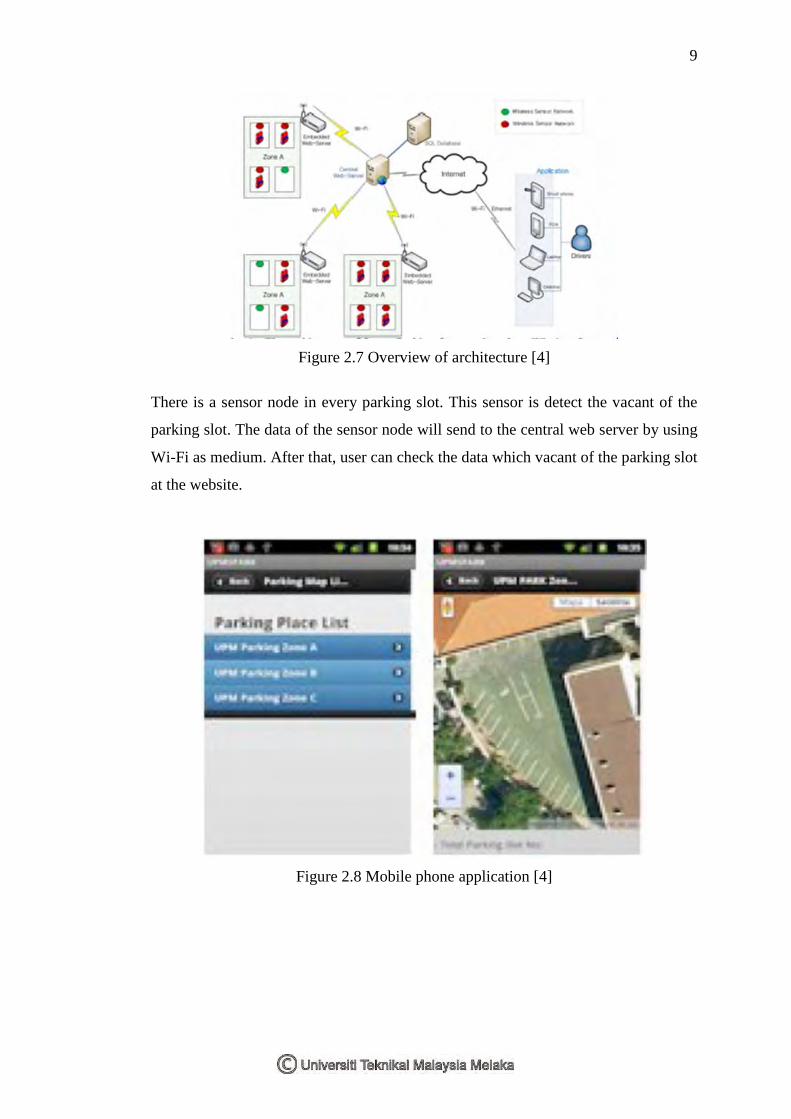
2.2.3 Smart Parking Service based on Wireless Sensor Networks
This project aim is to propose the prototype system of Smart Parking Services
based on Wireless Sensor Network. This system allows drivers of vehicle to search for
the free parking places effectively by using mobile application. The project is consists
of wireless sensor networks, embedded web server, central web server and mobile
application. [4]
9
Figure 2.7 Overview of architecture [4]
There is a sensor node in every parking slot. This sensor is detect the vacant of the
parking slot. The data of the sensor node will send to the central web server by using
Wi-Fi as medium. After that, user can check the data which vacant of the parking slot
at the website.
Figure 2.8 Mobile phone application [4]