hypothetical facility exercise data the lone pine · pdf filehypothetical facility exercise...
TRANSCRIPT

Exercise Data
The Hypothetical Facility—Lone Pine Nuclear Power Plant 1 The Twenty-Sixth International Training Course
Hypothetical Facility Exercise Data The Lone Pine Nuclear Power Plant (LPNPP)
Table of Contents
Section
Title
Page Section 1. Country of Lagassi Description and Map .................................................................. 2 Section 2. Lone Pine Nuclear Power Plant (LPNPP) Regional Map .......................................... 3 Section 3. LPNPP Introduction with Environmental and Physical Conditions ............................ 4 Section 4. LPNPP Site Layout and Response Force Location ................................................... 5
Table 1. Area Specific Access Controls and Physical Barriers ................................. 6 Section 5. Threat Data .............................................................................................................. 8 Section 6: Design Basis Threat ................................................................................................. 9 Section 7. Sabotage Scenarios for LPNPP .............................................................................. 11
Table 2. Hypothetical Areas in a Sabotage Protection Set for the LPNPP. ............ 11 Table 3. Sabotage Task Times .............................................................................. 12
Section 8. Response Forces at the Lone Pine Nuclear Power Plant ....................................... 13 Table 4. Response Force Deployment Data .......................................................... 15 Table 5. Average PPS Response Times for the entire 8-man Tactical Response
Team to Respond .................................................................................... 16 Section 9. Operations at Gates and Portals at LPNPP ............................................................ 17 Section 10. LPNPP Overview ................................................................................................... 21
Table 6. Other Nuclear Materials and Their Enrichment at the LPNPP .................. 28 Section 11. Detection Component Data .................................................................................. 32
Table 7. Intrusion Detection Component Class ...................................................... 32 Table 8. Access Control Detection Component Class ............................................ 33 Table 9. Human Surveillance Detection Component Class .................................... 34 Table 10. Contraband and CATEGORY 1 Detection Component Class ................ 35
Section 12. Delay Component Data ........................................................................................ 37 Table 11. Barrier Delay Component Class ............................................................. 37 Table 12. Security Officers Delay Component Class ............................................. 38 Table 13. Penetration Times—Fences ................................................................... 39 Table 14. Penetration Times—Gates .................................................................... 40 Table 15. Penetration Times—Walls ..................................................................... 41 Table 16. Penetration Times—Doors .................................................................... 44 Table 17. Cutting Rates for Reinforcement Bar Using 1-Meter Bolt Cutters .......... 47 Table 18. Cutting Rates for Reinforcement Bar Using Portable Oxygen/
Acetylene Cutting Torch........................................................................... 48 Table 19. Cutting Rates for Mild Steel Sheet & Plate Using Oxygen Acetylene
Cutting Torch or Iron Oxygen Burn Bar .................................................... 49 Table 20. Time Required to Set an Explosives Package as a Function of
Package Weight ...................................................................................... 50 Table 21. Running Rates ...................................................................................... 51 Table 22. Vehicle Rates for Experienced Drivers .................................................. 52

Exercise Data
The Hypothetical Facility—Lone Pine Nuclear Power Plant 2 The Twenty-Sixth International Training Course
Section 1. Country of Lagassi Description and Map Lagassi, the smallest of the regional republics, possesses large fossil fuel reserves and plentiful supplies of other minerals and metals. It also has a large agricultural sector featuring livestock and grain. Lagassi’s industrial sector rests on extracting and processing these natural resources and also on a growing machine-building sector that specializes in construction equipment, tractors, agricultural machinery, and some defense items. The country’s solid 3.5% economic growth is largely due to its booming energy sector, but also to economic reform, good harvests, and foreign investment. In order to prevent overdependence on the oil sector, the country has embarked on an industrial policy designed to diversify the economy by developing light industry and a nuclear energy infrastructure. Current issues include expanding the development of the country’s emerging nuclear energy resources, achieving an export capacity of electrical energy to border countries, and strengthening relations with neighboring states and other foreign powers.
Country Map of Lagassi

Exercise Data
The Hypothetical Facility—Lone Pine Nuclear Power Plant 3 The Twenty-Sixth International Training Course
Section 2. Lone Pine Nuclear Power Plant (LPNPP) Regional Map The hypothetical nuclear power plant, the Lone Pine Nuclear Power Plant (LPNPP) is located just to the east of the Hypothetical Atomic Research Institute (HARI) facility on a tributary of the Upper Lagassi River.
Lake Winowich Regional Map

Exercise Data
The Hypothetical Facility—Lone Pine Nuclear Power Plant 4 The Twenty-Sixth International Training Course
Section 3. LPNPP Introduction with Environmental and Physical Conditions The Lone Pine Nuclear Power Plant (LPNPP)
The hypothetical nuclear power plant, the Lone Pine Nuclear Power Plant is located just to the east of the Hypothetical Atomic Research Institute (HARI) facility on a tributary of the Upper Lagassi River. The LNPP was built in 1972 to produce 1150 Megawatts electrical for the Lagassi power grid. The LPNPP is located in the Republic of Lagassi, approximately 30 km (18 mi) east of Hashbakar.
Topography LNPP is located in the semi-arid steppes of Central Asia.
Vegetation Small shrubs, cacti, hardy desert trees, and grass are the only vegetation.
Wildlife Small animals inhabit the area, such as rabbits, squirrels, prairie dogs and coyotes. Birds of all sizes are also present.
Background Noise Regional earthquakes cause seismic disturbances occasionally. Some noise may also occur because of heavy passenger vehicle traffic and low-flying aircraft.
Climate/Weather The climate is a typical high-desert environment with approximately 300 clear days of bright sunshine per year. On cloudy days, there are areas with a high light-to-dark ratio because of moving cloud shadows. Rainfall is about 15 cm per year, with the majority occurring during thunderstorms in the late July-August rainy season. The spring is very windy for 2 to 3 months, with continuous winds of 2 to 5 km/hr and gusts up to 50 km/hr. Dry debris, dust, and dead vegetation are blown about during the windy season.

Exercise Data
The Hypothetical Facility—Lone Pine Nuclear Power Plant 5 The Twenty-Sixth International Training Course
Section 4. LPNPP Site Layout and Response Force Location
The LPNPP Site Controlled Area is surrounded by an unalarmed eight-foot high concrete fence to keep out trespassers. The LPNPP protected area is surrounded by two 2.5m high chain link fences with a well alarmed isolation zone between the two fences. The sensors in the isolation zone consist of active infra-red sensor in a self-protecting pattern and a fence vibration sensor on the inner fence. Alarm assessment is provided by Closed-Circuit Television (CCTV) cameras,

Exercise Data
The Hypothetical Facility—Lone Pine Nuclear Power Plant 6 The Twenty-Sixth International Training Course
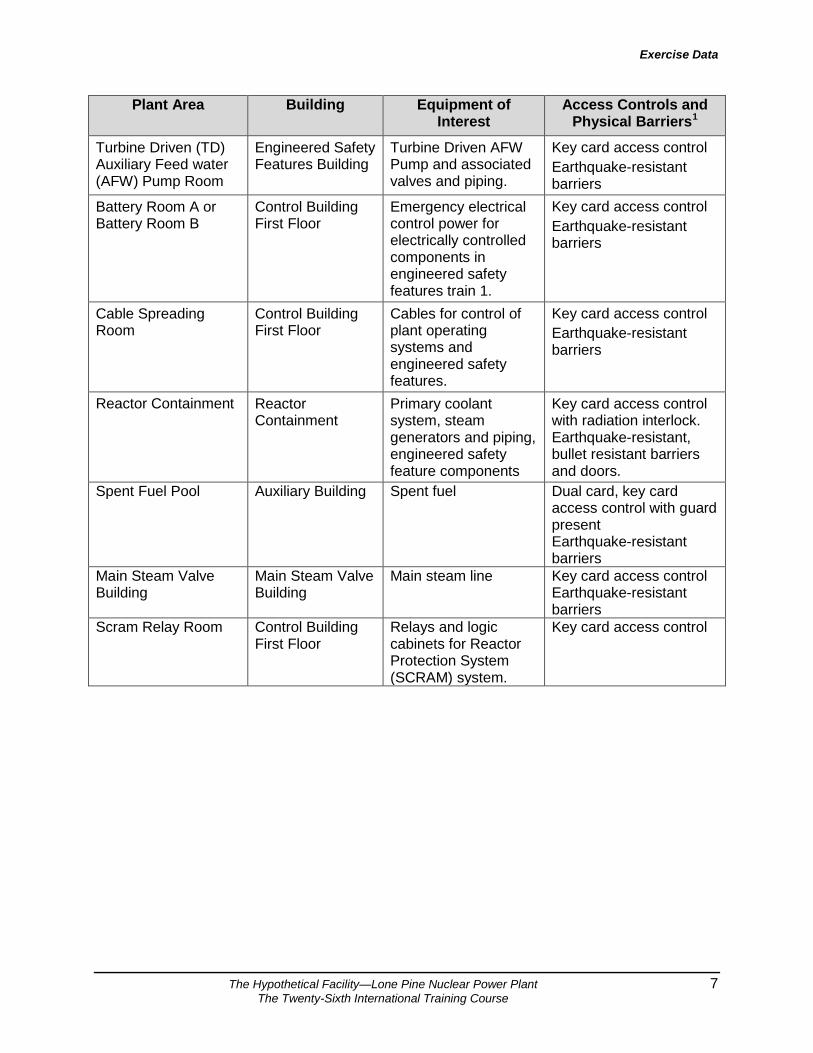
augmented by visual assessment by guards in 4 towers on the Protected Area perimeter (T1-T4). The vital areas within the LPNPP are enclosed by 20 cm thick concrete walls with access through .75 cm steel-plate water tight doors. Access is controlled by an electronic key card system that releases a door latch. In addition, each such door is alarmed with a balanced magnetic switch and CCTV to detect unauthorized entry. Table 1 indicates the area-specific access controls and physical barriers within the Protected Area. Table 1. Area Specific Access Controls and Physical Barriers
Plant Area Building Equipment of Interest
Access Controls and Physical Barriers1
Turbine Driven (TD) Auxiliary Feed water (AFW) Pump Room
Engineered Safety Features Building
Turbine Driven AFW Pump and associated valves and piping.
Key card access control Earthquake-resistant barriers
Battery Room A or Battery Room B
Control Building First Floor
Emergency electrical control power for electrically controlled components in engineered safety features train 1.
Key card access control Earthquake-resistant barriers
Cable Spreading Room
Control Building First Floor
Cables for control of plant operating systems and engineered safety features.
Key card access control Earthquake-resistant barriers
Reactor Containment Reactor Containment
Primary coolant system, steam generators and piping, engineered safety feature components
Key card access control with radiation interlock. Earthquake-resistant, bullet resistant barriers and doors.
Control Room Control Building Second Floor
Controls for plant operating systems and engineered safety features.
Key card access control. Bullet-resistant walls, doors, ceiling, floor, and windows.
Condensate Storage Tank (CST) and Piping
Plant Protected Area
Preferred Water Source for AFW System
Earthquake-resistant barriers. Lock and key access control to valves and other insider sabotage targets.
1 Access controls and physical barriers listed are in addition to the protected area physical barriers and access controls described in Table 4-1.
Exercise Data
The Hypothetical Facility—Lone Pine Nuclear Power Plant 7 The Twenty-Sixth International Training Course
Plant Area Building Equipment of Interest
Access Controls and Physical Barriers1
Turbine Driven (TD) Auxiliary Feed water (AFW) Pump Room
Engineered Safety Features Building
Turbine Driven AFW Pump and associated valves and piping.
Key card access control Earthquake-resistant barriers
Battery Room A or Battery Room B
Control Building First Floor
Emergency electrical control power for electrically controlled components in engineered safety features train 1.
Key card access control Earthquake-resistant barriers
Cable Spreading Room
Control Building First Floor
Cables for control of plant operating systems and engineered safety features.
Key card access control Earthquake-resistant barriers
Reactor Containment Reactor Containment
Primary coolant system, steam generators and piping, engineered safety feature components
Key card access control with radiation interlock. Earthquake-resistant, bullet resistant barriers and doors.
Spent Fuel Pool Auxiliary Building Spent fuel Dual card, key card access control with guard present Earthquake-resistant barriers
Main Steam Valve Building
Main Steam Valve Building
Main steam line Key card access control Earthquake-resistant barriers
Scram Relay Room Control Building First Floor
Relays and logic cabinets for Reactor Protection System (SCRAM) system.
Key card access control

Exercise Data
The Hypothetical Facility—Lone Pine Nuclear Power Plant 8 The Twenty-Sixth International Training Course
Section 5. Threat Data Intelligence Sources from the National Government • Items were recently confiscated from a political terrorist group’s hiding place, which was
located less than 200 km from the LPNPP. The items included internal engineering drawings of the LPNPP with circles drawn around the nuclear power plant and the waste storage; various weapons, including automatic weapons; and evidence of correspondence and communication with a foreign terrorist group. Interviews with property owners and residents indicated the group consisted of three to five men.
• Surveillance of several members of the terrorist group shows extensive travels in and out of the country.
• The economic and civil strife in a neighboring country has caused many refugees, some of which are suspected terrorists, to enter Lagassi illegally.
• Plans by a political terrorist group to attack shipments of nuclear material in a neighboring country were discovered.
• The local police intelligence reports several Special Forces members had been offered large cash payments to provide special training to unidentified individuals.
• The national intelligence organization reports terrorist groups are operating in cells of four to six individuals and compartmentalizing information.
• A group of international terrorists made threats that they have the ability (skilled members and weapons) to take over or create a radiological release of a foreign nuclear facility. They demanded the release of several political prisoners. Investigation proved that they do have the weapons and equipment they claimed they have.
Crime Study An analysis of crime incidents leads to the following conclusions:
• A major bank robbery was committed in the capital two months ago. Four robbers escaped with a large amount of money. Investigation shows the bank vault was breached by the sophisticated use of high explosives stolen from the local army base.
• Nationally, many thefts of highly valuable items have occurred. The crimes do not appear to be related to each other. It is speculated that several groups committed the crimes. Organized crime may be involved.
Professional Organizations • A recent meeting of the Lagassi Atomic Energy Ministry included a special session on
analysis of threat to nuclear facilities and material. No substantiated data on threats were available. However, the general feeling among members was that a threat to nuclear facilities does exist.
• During a meeting of the Industrialists Society, some corporate managers expressed concern that some of their employees had been approached by unnamed groups to help them carry out theft of valuable equipment and materials from the corporations. The employees had been offered large amounts of money.

Exercise Data
The Hypothetical Facility—Lone Pine Nuclear Power Plant 9 The Twenty-Sixth International Training Course
Section 6: Design Basis Threat Definition of the adversary
The adversary’s motivation is anti-nuclear terrorism. The adversary’s intention is sabotage.
Definition of Capabilities
Group Size
• Tactical team with 4 members Weapons
• Individual Weapons o Submachine gun. 9mm parabellum Cal. Open Sights.
Total of 4 magazines with 30 rounds each by member of tactical team.
o Sub automatic pistol. 9mm parabellum Cal. Total of 1 magazine with 15 rounds each by member of tactical team.
• Platoon Weapons Explosives
• Each team member of tactical team is equipped with 4kg. of plastic explosive.
• The tactical team has a bulk mass of explosives with an equivalent quantity of 250 kg. of TNT transported in a medium weight vehicle.
Communications Systems
• The team uses cellular phones and a two way radio system for communications.
Tools
• Portable manual tools available in the market. Modes of Transportation
• The team is transported by land using two vehicles at least. • One four wheel drive vehicle and one small van.
Technical Skills
• The team has technical skills enough to use his equipment, including weapons, explosives, communication and vehicles. They are familiar and well training in the tactics supported by such equipment.
• They have paramilitary training and experience and the know tactics for small groups.
Cyber Skills
• The adversary has basic cyber skills. Knowledge
• The team leader has information about targets location into NPP.

Exercise Data
The Hypothetical Facility—Lone Pine Nuclear Power Plant 10 The Twenty-Sixth International Training Course
• The team has basic information about technical aspects of NPP, including general lay-out, security, nuclear safety and radiation protection.
Funding
• Not described Insider Threat
• The tactical team would act in collusion with 1 passive and nonviolent insider.
• The insider has advanced technical knowledge about NPP and has access authorization for protected areas and some vital areas.
Supported Structure
• Not supported in the nearest surroundings of the nuclear site. Tactics
• Stealth and force.

Exercise Data
The Hypothetical Facility—Lone Pine Nuclear Power Plant 11 The Twenty-Sixth International Training Course
Section 7. Sabotage Scenarios for LPNPP The fresh fuel for the LPNPP produces negligible levels of radiation. Removing the fuel from the fuel rods and dispersing it would not have any appreciable radiological consequences; consequently, the fresh fuel is not an attractive sabotage target. Once the fuel has been used in the reactor it produces high levels of radiation and heat due to the decay of the fission products. Sabotage of the reactor that causes rupture of a significant number of the fuel rods in the core or in the spent fuel pool could cause release of radioactive material sufficient to exceed the unacceptable radiological consequence limit established by the Lagassi regulatory authority. Direct Attack Scenario A direct sabotage attack that would damage and disperse fuel from the core or spent fuel pool would require the adversary to enter the reactor hall or the spent fuel building and place a large explosive charge adjacent to the reactor or adjacent to the spent fuel pool. This type of attack is not feasible for this facility because the DBT does not include large quantities of man-portable explosives. The DBT only has explosives for one vehicle bomb and the vehicle cannot get close to the reactor building or the spent fuel building. Indirect Attack Scenario The fuel in the core and the spent fuel pool produces significant amounts of heat. The heat is removed by cooling of the water in the reactor and a forced air/water heat exchanger that discharges the waste heat to the atmosphere. A vital area identification study conducted for the reactor concluded that the locations in the following table are the ones that must be sabotaged to cause a radiological release. Consequently, all of these areas must be protected to prevent sabotage of the reactor. Table 2. Hypothetical Areas in a Sabotage Protection Set for the LPNPP.
Areas in Vital Area Set Location Credible Target for Design-Basis Threat
1. AFW-PUMP-RM-TD (Auxiliary Feedwater Turbine Driven Pump Room),
Engineered Safety Features Building
Yes
2. BATT-RM-A (Battery Room A) or BATT-Rm-B,
Control Building First Floor
Yes
3. CABLE-SPREAD (Cable Spreading Room) Control Building First Floor
Yes
4. CONTAINMENT (Reactor Containment) Reactor Containment
No
5. CONTROL-RM (Control Room)** Control Building Second Floor
Yes
6. CST (Condensate Storage Tank) and , CST-PIPING (Piping from Condensate Storage Tank)
Condensate Storage Tank and Piping
from Condensate Storage Tank
Yes
7. FUEL (Fuel Building) Fuel Building No

Exercise Data
The Hypothetical Facility—Lone Pine Nuclear Power Plant 12 The Twenty-Sixth International Training Course
8. MS-VALV-BLDG (Main Steam Valve Building)
Main Steam Valve Building
No
9. SCRAM-RELAY (Scram Relay Room)** Control Building First Floor
Yes
Note that the selection of areas and whether they are credible are hypothetical. Sabotage task times have been estimated, given the capabilities of the defined DBT. In the reactor hall, sabotage that prevents shutdown would require an adversary to go to the top of the reactor to mechanically jam the control rod drive mechanism, go to the pump compartment to disable the coolant pumps, and open the drain valve that would empty the coolant loop. The time estimated to complete these tasks is approximately fifteen minutes. From the control room, the adversary would need to trip the control rod insertion circuits, turn off power to the coolant pumps, and open the motor operated drain valve. The time required to complete the sabotage acts in the control room is estimated as thirteen minutes. A conservative estimate of the performance of the physical protection system of the facility against sabotage attacks will be based on an attack on the control room. Table 3. Sabotage Task Times
Areas in Vital Area Set Location Time to Sabotage Additional Areas
1. AFW-PUMP-RM-TD (Auxiliary Feedwater Turbine Driven Pump Room),
Engineered Safety Features Building
180 sec + 15 min 1
2. BATT-RM-A (Battery Room A) or BATT-Rm-B,
Control Building First Floor
300 sec + 15 min 1
3. CABLE-SPREAD (Cable Spreading Room)
Control Building First Floor
600 sec +15 min 0
4. CONTAINMENT (Reactor Containment)
Reactor Containment
No 0
5. CONTROL-RM (Control Room)** Control Building Second Floor
150 sec + 15 min 0
6. CST (Condensate Storage Tank) and , CST-PIPING (Piping from Condensate Storage Tank)
Condensate Storage Tank and
Piping from Condensate
Storage Tank
200 sec + 15 min 1
7. FUEL (Fuel Building) Fuel Building No 0
8. MS-VALV-BLDG (Main Steam Valve Building)
Main Steam Valve Building
No 0
9. SCRAM-RELAY (Scram Relay Room)**
Control Building First Floor
200 sec + 15 min 0

Exercise Data
The Hypothetical Facility—Lone Pine Nuclear Power Plant 13 The Twenty-Sixth International Training Course
Section 8. Response Forces at the Lone Pine Nuclear Power Plant Types of Response Force Personnel
The response force consists of three types of security personnel:
• unarmed guards • the onsite tactical response force • the offsite response team
Responsibilities of Response Force
These security personnel are responsible for:
• assessment of alarms • administrative duties such as access control and key service • routine patrol and staffing of fixed posts • armed response to all intrusion alarms
All posts and patrols have defined policies and procedures with which the security personnel must comply.
Supervisors For each shift, two supervisors are present: • Supervisor 1 supervises the guards that conduct administrative
duties and access control • Supervisor 2 is the commander of the tactical response team
Tactical Response Team Members
The onsite tactical response team has eight members (including the commander of the tactical response team), present during operational as well as non-operational hours. Four of these eight members are deployed in two two-person response teams that are on random patrol in unarmored vehicles at all times. All members are trained in close-quarters combat and have the authority to enter target locations to ensure the safety of critical assets and target material. The tactical response force commander for each shift is responsible for the oversight and supervision of all daily activities as well as emergency response to intrusion alarms.
Offsite Response Team
A 15-person offsite response team is deployed from the Regional Army Base near Hashbakar. This force is Special Weapons and Tactics (SWAT) trained and can arrive in 120 minutes after being notified.
Equipment: Guards
All guards are equipped with: • a straight baton • one set of handcuffs • a small flashlight • a handheld radio

Exercise Data
The Hypothetical Facility—Lone Pine Nuclear Power Plant 14 The Twenty-Sixth International Training Course
Equipment: Tactical Response Team
The tactical response team members are equipped with • a 38 caliber revolver with 25 rounds and
an automatic submachine gun with a total of 5 magazines • Both weapons are carried fully loaded but without a round in
the chamber. • a straight baton • handcuffs • flashlight • handheld radio • 2 vehicles not armored
Training Classroom training (all security staff):
• access control procedures • use of force continuum • target locations • response procedures • chain of command • other administrative responsibilities
Tactical response team personnel receive additional training on:
• close quarters combat • recapture and recovery of nuclear material/facilities • advanced firearms training for both the revolver and the
automatic submachine gun Firearms training:
• The tactical response team personnel are required to qualify with their firearms four times a year
• Tactical response teams are provided with firearms training each month to ensure proficiency
All response force personnel receive routine physical fitness training when in the training mode.
Alarm Stations and Communication
The Central Alarm Station (CAS) is located in P11 and is staffed by two guards during the day and one guard at night. All alarms are received at the CAS (P11) and SAS (P10). Alarms from the Lone Pine facility are assessed by CAS using video cameras. The guard is responsible for assessing alarms and communicating them to the response forces. The Secondary Alarm Station (SAS) is located in P10, the Main Access Control Point and is staffed by two guards during the day and one guard at night. The SAS monitors the activities of the CAS to ensure appropriate actions are taken. The CAS only relinquishes monitoring and control during maintenance and other temporary facility outages. Both the CAS and the SAS are equipped with:
• 100-watt radios that can communicate to all posts and patrols within the boundaries of the Institute.

Exercise Data
The Hypothetical Facility—Lone Pine Nuclear Power Plant 15 The Twenty-Sixth International Training Course
• 2 telephone lines. One is linked to each fixed post via a buried telephone cable and the second telephone is a direct link to the Ministry of Interior headquarters located in the city.
Extensive testing of the communication system has shown that the radio communications are good throughout the Institute with the exception of the lower level interiors of the Lone Pine facility buildings. Testing concluded that security personnel on these lower levels are able to monitor transmissions from both the CAS and the SAS but are unable to transmit to the CAS and the SAS with their handheld radios. All handheld radios and fixed posts are equipped with a duress switch to allow a covert signal to the CAS and SAS of unauthorized activity. When the CAS or SAS receive a duress alarm, the response team is notified and the response force commander initiates a tactical response. Supervisor 1, the guard force commander, is normally located in the CAS during the day shift.
Deployment of Response Force
The response force is deployed as described in the following table.
Table 4. Response Force Deployment Data
Post No.
Description Security Personnel
No. of Personnel Workdays Non-
workdays S1 Guard Commander (Supervisor 1) Lieutenant 1 1 P10 Lone Pine Main Access Control Point Guard 4-102 3 P10 Secondary Alarm Station Guard 2 1 P11 Central Alarm Station Guard 2 1 P15 Northwest Lone Pine Vehicle Access
Control Point Guard 1 1
T1-T4 Four Guard Towers Guard 4 4 S2 Tactical Response Force Commander Response
Captain 1 1
P11 Onsite Tactical Response Forces (Stationed in the Security Building)
Response Force 3 3
P16 Two-person vehicle patrol Response Force 2 2 P17 Two-person vehicle patrol Response Force 2 2
Offsite Offsite Response Force Response Forces 15 15 Totals 38 34
Response Procedure for Response Force
All alarms are received and assessed at the Central Alarm Station (CAS). The Secondary Alarm Station (SAS) verifies the CAS operator’s assessment to ensure all alarms are properly assessed. The CAS operator immediately notifies the Commander of the Response Force so
2 The LPNPP Main Access Control Point staffing is increased from 4 to 10 beginning 45 minutes before each LPNPP shift change and reduces back to 4 at 30 minutes after the LPNPP shift change. The six guards are re-deployed to other plant duties.

Exercise Data
The Hypothetical Facility—Lone Pine Nuclear Power Plant 16 The Twenty-Sixth International Training Course
preparations for deployment can begin by the tactical team. In addition, institute procedures require that the nearest vehicle patrol also be dispatched to the point of the alarm to provide additional assessment and to observe and report any unauthorized activity. The three response force members stationed in the Security Building and the tactical response force commander collect their firearms from the armory in the Security Building, and prepare to respond either by foot or vehicle to a location directed by their commander. The farthest of the two-man vehicle patrols also responds. Both two-person patrols have their weapons with them in their vehicles. Once all eight of tactical response team members arrive at the appropriate location, they deploy as a team and proceed with operations to enter the facility and ensure the protection of material and assets.
Response Force Performance Data
The Institute has conducted extensive performance testing of the CAS/SAS in the areas of alarm assessment, alarm communication, and response force notification and has recorded preparation, travel and deployment times for onsite tactical response forces alarms at the Lone Pine Nuclear Power Plant. The average times are listed in the table below. Procedures require that all tactical responders be available to respond to an alarm from P-10. All tactical responders are fully equipped with their duty gear with the exception of their rifles, which are kept in storage in the armory until needed. The CAS provides information to the tactical response force during a security incident. Should the CAS operator become unable to continue to direct the response, the SAS operator takes his place. Note that the first two-person vehicle patrol can arrive in 30-60 seconds.
Table 5. Average PPS Response Times for the entire 8-man Tactical Response Team to Respond
Alarm Location Response Time Protected Area Fence 60-150 seconds Control Building 120-150 seconds Engineered Safety Features Building 60-90 seconds Condensate Storage Tank 60-90 seconds Reactor Containment 5-10 minutes

Exercise Data
The Hypothetical Facility—Lone Pine Nuclear Power Plant 17 The Twenty-Sixth International Training Course
Section 9. Operations at Gates and Portals at LPNPP Employee Vehicle Entrance (P12) The gate to the entrance is unlocked and open during normal working hours and locked during off-shifts. Guard Force Staffing: During operational hours, 2 guards are present; one at the gate and one available for other duties. At night, 1 guard is present.
1. On entry, vehicles drive slowly and all passengers show the guard their badges. 2. The guard looks inside the vehicle and allows it to pass. 1. On exit, the vehicles must stop and wait for the guard to wave them out. 2. A guard observes exiting vehicle for proper actions.
Main Protected Area Access Control Point (P10) Guard Force Staffing: 1 guard is present at P10 at all times. If a vehicle requires entry into the LPNPP, the guard at P10 calls another guard to assist with the vehicle entry. Personnel entering the Protected Area undergo a search for contraband by passing through metal detectors. Hand carried items are X-rayed and passed through metal detectors. Suspicious items are physically searched and individuals who fail the metal detector search are “wanded” with hand held metal detectors or subjected to a pat down search. After verification that individuals are not carrying contraband, they undergo a badge exchange, turning in their Institute picture badges and picking up their LNPP picture badges and key cards. The personnel then enter the LNPP Protected Area via a turnstile operated by their key cards. The guards who perform the badge exchange are in bullet resistant enclosures and have a “panic” button that will override the key card reader, freezing the turnstiles and precluding any entry to the Protected Area. In a Site Emergency, the turnstiles can also be reconfigured to permit egress from the Protected Area to facilitate evacuation. The layout of the entry control section of the LPNPP Main Protected Area Access Control Point is shown below. Personnel exiting the Protected Area undergo a search for SNM by passing through metal and SNM detectors. Hand carried items are X-rayed. Suspicious items are physically searched and individuals who fail the metal detector search are “wanded” with hand held metal detectors and SNM detectors or subjected to a pat down search. After verification that individuals are not carrying SNM, they undergo a badge exchange, turning in their LPNPP picture badges and key cards and picking up their Institute picture badges. The personnel then exit the LPNPP Protected Area via unlocked doors.

Exercise Data
The Hypothetical Facility—Lone Pine Nuclear Power Plant 18 The Twenty-Sixth International Training Course
LPNPP Main Protected Area Access Control Point

Exercise Data
The Hypothetical Facility—Lone Pine Nuclear Power Plant 19 The Twenty-Sixth International Training Course
LPNPP Main Vehicle Portal (P10)
1. On entry, the vehicle’s driver drives the vehicle up to the outer gate. 2. The driver may push an electric buzzer at the gate to alert the guard. 3. The sensor is put in “access” mode and then the guard at P10 unlocks and opens
the outer gate. 4. The vehicle enters the portal and then the driver leaves the vehicle and goes back
outside. 5. The guard shuts and locks the outer vehicle gate. 6. The driver enters the pedestrian portal, is subjected to the same checks as all
personnel entering the protected area, and must remain in the portal until the vehicle has been inspected.
7. The guard inspects the vehicle for contraband while it is still in the vehicle portal. 8. When the inspection is complete the guard unlocks and opens the inner vehicle
gate. 9. The driver may exit the personnel portal, reenter the vehicle, and drive into the
area. 10. The inner gate is closed and locked by the guard. 11. The sensor is put in “active” mode.
1. On exit, the process is reversed. The vehicle’s driver drives the vehicle up to the
inner gate. 2. The driver may push an electric buzzer at the gate to alert the guard. 3. The sensor is put in “access” mode and the guard at P10 unlocks and opens the
inner gate. 4. The vehicle enters the portal and then the driver leaves the vehicle and goes back
inside the area. 5. The guard shuts and locks the inner vehicle gate. 6. The driver enters the pedestrian portal, is subjected to the same checks as all
personnel leaving the protected area, and must remain in the portal until the vehicle has been inspected.
7. The guard inspects the vehicle for stolen material while it is still in the vehicle portal.
8. When the inspection is complete, the guard unlocks and opens the outer vehicle gate.
9. The driver may exit the personnel portal, reenter the vehicle, and proceed. 10. The guard shuts and locks the outer gate. 11. The sensor is put in “active” mode. LPNPP Protected Area Vehicle Gate (P15) This gate is normally closed and locked with high security padlocks. When a delivery vehicle arrives, 2 guards are dispatched to the gates. They verify that the individuals driving the vehicle have LPNPP badges (exchange badges) permitting access to the LPNPP Protected Area or have the required guard force escorts. They review the manifest or other documents to verify that the vehicle requires entry to the LPNPP. The guards then contact the LPNPP Control Room and verify that the vehicle is expected. Once they have verified that the vehicle is expected, they inspect it for contraband. If the vehicle passes inspection, the guards contact the Central Alarm Station (CAS) requesting that the Protected Area intrusion detection system zone at the gates be placed in the access mode. The guards then unlock the vehicle gates to permit the vehicle entry to the LPNPP Protected Area. After the vehicle has entered the Protected Area, the gates are locked and the Protected Area intrusion detection system zone at the gates is returned to the secure mode. When a

Exercise Data
The Hypothetical Facility—Lone Pine Nuclear Power Plant 20 The Twenty-Sixth International Training Course
vehicle needs to exit the Protected Area, the driver notifies the Central Alarm Station, which dispatches 2 guards to the gate. On exit, vehicles are scanned with a radiation monitor to ensure that there is no contamination and searched for Special Nuclear Material (SNM). Once vehicles are verified not to be contaminated and not to have unauthorized SNM, they are permitted to exit. The contamination scan and SNM search are performed inside the Protected Area with the vehicle gates locked.

Exercise Data
The Hypothetical Facility—Lone Pine Nuclear Power Plant 21 The Twenty-Sixth International Training Course
Section 10. LPNPP Overview Note: The description of this reactor is purely hypothetical. Students interested in factual reactor design information are directed to IAEA publication, “Directory of Nuclear Research Reactors” or other technical references. General Description The LPNPP Site is located in a semi-arid high desert. The LPNPP is a two-loop pressurized light water reactor with a reactor power level of 1,150 megawatts electric at full power. LPNPP is a dual cycle nuclear power plant consisting of a reactor, a closed primary coolant loop connected to the reactor vessel, and a separate power conversion system (secondary coolant) for the generation of electricity. The primary coolant is light water under pressure (typically 2,235 psi) containing chemicals to control the nuclear reaction (boric acid, referred to as “chemical shim”) and corrosion. The secondary coolant is also light water containing chemicals to control corrosion. The primary coolant system transfers heat from the reactor core to the steam generators, which transfer heat to the secondary coolant, causing it to boil. The steam passes from the steam generators to the turbine generator where the thermal energy of the steam is converted into mechanical and then electrical energy. The steam is condensed in the main condenser and the secondary coolant is returned to the steam generators by the feed water pumps. The use of a dual cycle minimizes the quantities of fission products released to the main turbine, condenser and other secondary plant components and subsequent release to the atmosphere. The reactor is equipped with a once-through cooling system. The entire Reactor Coolant System (RCS), including the steam generators, is located in the Containment Building, which isolates the radioactive RCS from the environment in the event of a leak. The basic arrangement is shown in the figure below. However, the LPNPP is a once-through cooling system so the cooling tower was never built and the river supplies the cooling. The intake structure houses the circulating water system, the service water system, and the screen wash system. The intake structure consists of six intake bays, each with a traveling water screen and a circulating water pump. The capacity of this pump house is approximately 1,000,000 gallons per minute (GPM). The following major systems are included in the intake structure:
a) Circulating Water System. The six pumps of this system take water from the river and provide cooling to the main condenser. This cooling water is then discharged via a cooling canal to the river.
b) Service Water System. The four pumps of this system also take water from the river and discharge via the cooling canal to the river. Service water is used to cool other systems, such as the primary and secondary (steam) system, component cooling system, containment cooler, diesel generators and other heat exchangers.
c) Screen Wash System: Six traveling water screens are provided to remove trash and foreign mater from the water used to supply the service and circulating water systems.”

Exercise Data
The Hypothetical Facility—Lone Pine Nuclear Power Plant 22 The Twenty-Sixth International Training Course
Basic PWR Arrangement Engineered Safety Features (ESF) Building
The systems in the ESF Building are designed to mitigate the consequences of loss of coolant accidents (LOCAs) and plant transients. The ESF is designed to provide emergency cooling water to the reactor core to maintain fuel rod integrity in the event that normal cooling water (the river) is lost. This prevents the release of radioactive fission products to the containment and possibly to the environment. The ESF systems also serve to maintain the structural integrity of the containment if the pressurized primary coolant were released into the containment atmosphere during a LOCA. The ESF Building also houses the Auxiliary Feedwater System that provides feedwater to cool the steam generators during very low power operations and during transients that cause the main feedwater system to be unavailable. The ESF Building houses the Auxiliary Feedwater System (AFW). The AFW is the vital equipment in the ESF. This system, consisting of two motor-driven and one turbine-driven pump takes suction from the Condensate Storage Tank and supply feedwater to the steam generators to remove heat from the primary coolant system during very low power operations and during transients that cause the main feedwater system to be unavailable. The turbine drive pump is powered by steam from the steam generator that it supplies with feedwater so that the heat from the steam generator provides the motive power for the pump. The auxiliary feedwater pumps are flow cooled.

Exercise Data
The Hypothetical Facility—Lone Pine Nuclear Power Plant 23 The Twenty-Sixth International Training Course
Control Building

Exercise Data
The Hypothetical Facility—Lone Pine Nuclear Power Plant 24 The Twenty-Sixth International Training Course
The Control Building is a two level structure. The lower level houses the switchgear and motor control centers that control and power motor-driven pumps, motor-operated valves and other electrical plant electrical equipment. The lower level also contains the battery rooms that supply backup instrumentation and control power, the electronics that control the reactor protection system (in the SCRAM Relay Room), and the Cable Spreading Room where the instrumentation and control cables from the Control Room are routed to the appropriate instruments, motor control centers, and other control equipment. The lower level also contains (in the SCRAM Relay Room) the auxiliary shutdown panel from which the reactor can also be monitored, controlled and safely shutdown should the control room become damaged or unavailable. The arrangement of equipment in the lower level of the Control Building is shown below.
Control Building Lower Level

Exercise Data
The Hypothetical Facility—Lone Pine Nuclear Power Plant 25 The Twenty-Sixth International Training Course
The upper level of the Control Building houses the main control board and the plant computer. Control of both the reactor and turbine generator can be accomplished from the control room, which contains all instrumentation and control equipment required for start-up, operation, and shutdown under both both normal and accident conditions. The arrangement of equipment in the upper level of the Control Building is shown below
Control Building Upper Level

Exercise Data
The Hypothetical Facility—Lone Pine Nuclear Power Plant 26 The Twenty-Sixth International Training Course
Fuel Building
The fuel building is designed as a transfer and storage area for new and used fuel. During operation of the reactor uranium is consumed and radioactive fission products are created. The average residence time of fuel in the core is about three years and the reactor is refueled annually. Thus, one-third of the reactor is refueled every year. After removal from the reactor, the fuel is called “used fuel” or "spent fuel" and is highly radioactive. It is handled remotely using special under water fuel handling equipment. The spent fuel is removed from the reactor vessel and placed in the spent fuel storage pool for at least six months. During this time, the shorter-lived radioactive fission products decay and the radioactivity level is reduced by 99.9 percent. The fuel can then be shipped to another storage facility or a reprocessing plant. If the spent fuel is shipped, it is placed in specially designed shipping casks made of steel and lined with lead. The casks range in size from 25 to 100 tons. The smallest casks can be transported by truck, but the largest must be shipped by rail. Fresh fuel is stored in the new fuel casks and transferred to racks in the spent fuel storage pool prior to refuelling. The door to the new fuel portion of the building is a 30 cm dual wooden vehicle door with metal sheeting and a personnel emergency exit door. It is equipped with BMS sensors and CCTV assessment. All of the fuel assemblies in the core are of a similar design. The fuel rods in an assembly are arranged in a square array with 17 rod locations per side or 289 rod locations per assembly (some assembly designs may have fewer fuel rods). Of the 289 possible rod locations, 264 actually contain fuel rods. The other 25 locations are filled by 24 guide tubes for the rod cluster control assemblies (control rods) and one guide thimble for incore nuclear instrumentation and experiments. Each fuel rod contains uranium oxide fuel pellets. The uranium 235 enrichment in the fuel assemblies is either 2.1, 2.6, or 3.1 weight percent. The varying uranium enrichments help ensure uniform neutron flux throughout the active area of the reactor core. (The higher enriched fuel assemblies are loaded around the boundary of the core.) A core loading consists of 193 fuel assemblies. Each fuel assembly contains about 1,154 pounds of uranium oxide. With the zircalloy clad and other mechanical components, each fuel assembly weighs about 1,500 pounds, three quarters of a ton. The Fuel Pool Cooling and Purification System, consisting of cooling and purification pumps, heat exchangers, filters and dimineralizers, is designed to maintain clarity and purity of the fuel pool water and to keep the stored spent fuel at a cool temperature. The arrangement of the equpment in the Fuel Building is shown below.

Exercise Data
The Hypothetical Facility—Lone Pine Nuclear Power Plant 27 The Twenty-Sixth International Training Course
Fuel Building Layout

Exercise Data
The Hypothetical Facility—Lone Pine Nuclear Power Plant 28 The Twenty-Sixth International Training Course
Table 6. Other Nuclear Materials and Their Enrichment at the LPNPP
Experiment Materials
1. Three kilograms total of highly radioactive medical radionuclides, including Cesium, Americium, and Strontium90.
2. Experiments and metal are used in other irradiation and activation experiments.
Location Form of Material
Amount of Material on Site (wt% enrichment)
Total Isotope Amounts
Level of Radiation
Fuel Pool
Pu Experiments
HEU metal Other Sources
9.3 kg 239PuO2 (100% 239Pu)
23 Kg U (95% 235U) Cs, Am, Sr
8kg 239Pu
22 Kg 235U 3 kg total
Low
Low High
New fuel casks
HEU-metal Experiments (9 units)
12.6 kg U (93% 235U) 11.7 kg 235U Low
Vats Liquid Mixture (2 vats, 2,000 liters ea)
Trace Amounts of Pu (75% 239Pu) and U
(18% 235U) trace
High 0.5-1.0 Gy/hr
at 1m
Sheds Solidified Waste (50 containers)
Trace Amounts of Pu(31% 239Pu) and
U(12% 235U) trace
High <0.5 Gy/hr at
1m

Exercise Data
The Hypothetical Facility—Lone Pine Nuclear Power Plant 29 The Twenty-Sixth International Training Course
Condensate Storage Tank and Piping from Condensate Storage Tank
The condensate storage tank serves as the normal supply to the auxiliary feedwater pumps. A minimum amount of water is required by technical specifications to meet design considerations for cooldown. The hotwell level control system can affect the level in the condensate storage tank by either making up to the hotwell if the level in the hotwell is low or rejecting water to the condensate storage tank if the level in the hotwell is too high. If the required minimum level in the condensate storage tank is approached, an alarm is sounded in the main control room to prompt operator action before the limit is violated. In the event of a loss of off-site power, the reactor coolant pumps lose power and no longer supply forced circulation of coolant through the core. The auxiliary feedwater system is essential for core decay heat removal under these conditions. Since the condenser circulating water pumps also lose power, the condenser steam dumps are not available for steam release from the steam generators. The steam generator power operated relief valves are used to relieve the steam. The auxiliary feedwater system is also essential in supporting core decay heat removal during a small break LOCA (SBLOCA). During a SBLOCA, the injection flow rate from the emergency core cooling systems is not sufficient to provide adequate flow through the core for decay heat removal because of the reactor coolant system backpressure effect on

Exercise Data
The Hypothetical Facility—Lone Pine Nuclear Power Plant 30 The Twenty-Sixth International Training Course
emergency core cooling system flow and the slow reactor coolant system depressurization rate resulting from the coolant discharge through the small break. Decay heat removal via the reactor coolant system and heat transfer to the steam generators is necessary for core cooling considerations under small break loss of coolant accident conditions. NOTE: During a large break loss of coolant accident, the emergency core cooling system flow alone is adequate to provide core cooling since the rapid reactor coolant system pressure reduction allows a much higher emergency core cooling system flow rate through the core. Since auxiliary feedwater is necessary to mitigate the consequences of an accident as discussed previously, the complete auxiliary feedwater system, with the exception of the suction supply from the condensate storage tank, has been designed to Seismic Category I specifications. In the event that the condensate storage tank is damaged or destroyed, the Seismic Category I service water system is available as a backup suction for the auxiliary feedwater pumps. The auxiliary feedwater pumps will automatically start upon actuation of one of the following start signals:
1. Steam generator low-low level, 2. Loss of both main feedwater pumps, 3. Loss of one main feedwater pump with power above 80%, 4. An engineered safety features actuation signal, or 5. Loss of off-site power.

Exercise Data
The Hypothetical Facility—Lone Pine Nuclear Power Plant 31 The Twenty-Sixth International Training Course
Three Dimensional Site Layout To aid in visualizing the layout of the LPNPP, the image below provides a three dimensional presentation of the site layout looking from the Northwest and Southeast. This drawing shows the major features of the plant.

Exercise Data
The Hypothetical Facility—Lone Pine Nuclear Power Plant 32 The Twenty-Sixth International Training Course
Section 11. Detection Component Data Each of the following tables represents a detection component class. Within each table the component types and descriptions are listed with the probability of detection by adversary defeat method or adversary attribute. Table 7. Intrusion Detection Component Class Component
Type Component Description
No Equipment PD
Hand Tools
PD
Power Tools
PD
High Explosives
PD
Land Vehicle
PD Exterior Sensors
Seismic Buried Cable 0.5 0.5 0.5 0.5 0.9 Electric field 0.5 0.3 0.3 0.5 0.9 Infrared 0.8 0.4 0.4 0.5 0.8 Microwave 0.8 0.7 0.7 0.7 0.9 Video motion 0.8 0.6 0.6 0.7 0.9 Multiple non-complementary
0.9 0.8 0.8 0.8 0.99
Multiple complementary
0.99 0.95 0.95 0.99 0.99
Interior Sensors
Sonic 0.5 0.5 0.5 0.5 N/A Capacitance 0.5 0.5 0.5 0.5 N/A Video Motion 0.5 0.5 0.5 0.5 N/A Infrared 0.5 0.5 0.5 0.5 N/A Ultrasonic 0.5 0.5 0.5 0.5 N/A Microwave 0.5 0.5 0.5 0.5 N/A Multiple non-complementary
0.75 0.75 0.75 0.75 N/A
Multiple complementary
0.9 0.9 0.9 0.9 N/A
Position Sensors
Position Switch 0.5 0.2 0.2 0.2 N/A Balanced Magnetic Switch
0.8 0.8 0.8 0.8 N/A
Fence Sensors
Taut Wire 0.5 0.25 0.25 0.75 0.85 Vibration 0.5 0.1 0.1 0.75 0.85 Strain 0.1 0.1 0.1 0.1 0.9 Electric Field 0.5 0.4 0.4 0.75 0.9 Multiple Sensors 0.75 0.5 0.5 0.8 0.9
Barrier Sensors
Vibration 0.9 0.4 0.4 0.9 N/A Glass Breakage 0.9 0.6 0.6 0.9 N/A Conducting Tape 0.8 0.2 0.2 0.9 N/A Grid Mesh 0.9 0.6 0.6 0.95 N/A Multiple Sensors 0.99 0.9 0.9 0.99 N/A
Helicopter Detector
Radar 0.1 Sonic 0.1

Exercise Data
The Hypothetical Facility—Lone Pine Nuclear Power Plant 33 The Twenty-Sixth International Training Course
Table 8. Access Control Detection Component Class Component
Type Component Description Independent
PD Land
Vehicle PD
ID Verification Casual Recognition 0.02 Credential 0.05 Credential and PIN 0.35 Picture Badge 0.1 Picture Badge and PIN 0.6 Exchange picture badge 0.5 Exchange picture badge and PIN 0.8 Retinal scan and PIN 0.99 Hand geometry and PIN 0.95 Speech pattern and PIN 0.95 Signature dynamics and PIN 0.95 Fingerprint and PIN 0.95
Personnel Access Authorization Check
General observation of authorization
0.1
Authorization verification each time location is accessed
0.6
Two Person Rule
Presence in area 0 Within sight 0.1 Dedicated observation 0.5 Dedicated observation with alarm 0.95
Vehicle Authorization Check
Authorization form check 0.35 Serial number verification 0.45 Visual check of insignia/ license plate
0.15

Exercise Data
The Hypothetical Facility—Lone Pine Nuclear Power Plant 34 The Twenty-Sixth International Training Course
Table 9. Human Surveillance Detection Component Class Component
Type Component Description
No Equipment
PD
Small Arms
PD
Light Antitank Weapons
(LAW) PD
Independent of threat attribute
PD
SO at Post Observation
Duress, LAW protected 0.8 0.8 0.8 Duress, small arms protected
0.8 0.8 0.45
Duress, small arms protected: LAW protected on alert
0.8 0.8 0.45
Duress, unprotected 0.8 0.45 0.45 Duress, unprotected: LAW protected position on alert
0.8 0.45 0.45
Duress, unprotected: small arms protected position on alert
0.8 0.45 0.45
No duress, LAW protected
0.8 0.8 0.45
No duress, small arms protected
0.8 0.45 0.45
No duress, small arms protected: LAW protected position on alert
0.8 0.45 0.45
No duress, unprotected 0.8 0 0 No duress, unprotected: LAW protected position on alert
0.8 0 0
No duress, unprotected: small arms protected on alert
0.8 0 0
SO in Tower Observation
LAW resistant tower 0.05 0.05 0.02 Small arms resistant 0.05 0.05 0.02
SO on Patrol
Random 0.02 Scheduled 0.01
General Observation
Personnel always in vicinity
0.02
Personnel generally in vicinity
0.01

Exercise Data
The Hypothetical Facility—Lone Pine Nuclear Power Plant 35 The Twenty-Sixth International Training Course
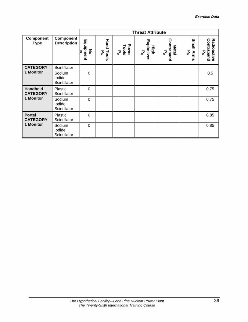
Table 10. Contraband and CATEGORY 1 Detection Component Class Threat Attribute
Component Type
Component Description
No
Equipment
PD
Hand Tools
PD
Power
Tools P
D
High
Explosives P
D
Metal
Contraband
PD
Small A
rms
PD
Radioactive
Contraband
PD
Explosives Detector
Animal Olfaction
0 0.1
Handheld vapor collection
0 0.45
Thermal Neutron
0 0.25
Vapor Collection
0 0.35
Handheld Metal Detector
Ferrous and solid lead materials
0 0.85 0.75 0.25 0.5
Ferrous materials and all forms of lead
0 0.85 0.75 0.25 0.5
Ferrous materials only
0 0.85 0.75 0.25 0.5
Item Search Cursory 0 0.1 0.1 0.1 0.1 Rigorous 0 0.75 0.75 0.45 0.65
Personnel Search
Pat down 0 0.9 0.9 0.3 0.9 Strip inspection
0 0.9 0.9 0.9 0.9
Portal Metal Detector
Ferrous and solid lead materials
0 0.9 0.9 0.8 0.6
Ferrous materials and all forms of lead
0 0.9 0.9 0.8 0.6
Ferrous materials only
0 0.9 0.9 0.8 0.6
Vehicle Search
Cursory 0 0.1 0.1 0.1 0.1 Rigorous including cargo
0 0.5 0.5 0.25 0.4
X-Ray Inspection
Standard 0 0.9 0.9 0.6 0.9
Drive thru Plastic 0 0.5
Exercise Data
The Hypothetical Facility—Lone Pine Nuclear Power Plant 36 The Twenty-Sixth International Training Course
Threat Attribute Component
Type Component Description
No
Equipment
PD
Hand Tools
PD
Power
Tools P
D
High
Explosives P
D
Metal
Contraband
PD
Small A
rms
PD
Radioactive
Contraband
PD
CATEGORY 1 Monitor
Scintillator Sodium Iodide Scintillator
0 0.5
Handheld CATEGORY 1 Monitor
Plastic Scintillator
0 0.75
Sodium Iodide Scintillator
0 0.75
Portal CATEGORY 1 Monitor
Plastic Scintillator
0 0.85
Sodium Iodide Scintillator
0 0.85

Exercise Data
The Hypothetical Facility—Lone Pine Nuclear Power Plant 37 The Twenty-Sixth International Training Course
Section 12. Delay Component Data Each of the following tables represents a delay component class. Within each table the component types and descriptions are listed with the delay times by adversary defeat method. Table 11. Barrier Delay Component Class
Component Type
Component Description
No Equipment
(sec)
Hand Tools (sec)
Power Tools (sec)
Explosives (sec) Land
Vehicle (sec) Stage
1 Stage
2 Walls 60 cm reinforced
concrete wall Infinite Infinite 900 180 300 Infinite
30 cm reinforced concrete wall Infinite Infinite 840 120 54 N/A
20 cm reinforced concrete wall Infinite Infinite 600 120 0 N/A
Wood studs and sheetrock 60 30 30 30 0 N/A
Doors 60 cm steel and concrete rolling door Infinite Infinite 930 200 300 N/A
30 cm steel and concrete rolling door Infinite Infinite 640 160 54 N/A
30 cm wood door with metal sheeting Infinite Infinite 530 160 30 N/A
10 cm wood door with metal sheeting Infinite 300 180 30 0
5 for large
vehicle door 5 cm wood door Infinite 12 12 12 0 N/A 5 cm wood door with glass panel Infinite 12 12 12 0 N/A
.75 cm steel plate door Infinite 300 30 30 0 N/A
Class V or VI vault door Infinite 480 60 60 0 N/A
Steel turnstile Infinite 72 18 18 0 N/A Miscellaneous Barriers
High security padlock Infinite 90 60 30 0 N/A
Concrete Block Vehicle Barrier 0 300 300 30 0 5
2.5 m chain link mesh fence 10 10 10 10 0 1
Welded wire fabric fence 10 10 10 10 0 1
2.5 m concrete panel wall 10 10 10 10 0 N/A
Tempered glass window 5 5 5 5 5 N/A
Electromagnetic Strike Lock 15 10 5 5 2 N/A

Exercise Data
The Hypothetical Facility—Lone Pine Nuclear Power Plant 38 The Twenty-Sixth International Training Course
Table 12. Security Officers Delay Component Class
Component Type Component Description
No Equipment
(sec)
Small Arms (sec)
Light Antitank Weapons
(LAW) (sec)
SO at Post Delay
Unprotected post 30000 0 0 Small arms protected post 30000 30 0 Unprotected post normally but moves to small arms protected position on alert
30000 30 0
LAW protected post 30000 125 125 Unprotected post normally but moves to LAW protected position on alert
30000 125 125
Small arms protected post normally, but moves to LAW protected position on alert
30000 125 125
SO in Tower Delay
Small arms resistance 60 30 0 LAW resistant tower 125 125 60

Exercise Data
The Hypothetical Facility—Lone Pine Nuclear Power Plant (LPNPP) 39
Table 13. Penetration Times—Fences
Penetration Time (Minutes) Barrier Description Penetration
Equipment Equipment Weight (kg)
Min. Mean Max. Standard Deviation
2.5-m chain-link mesh with outriggers 4-mm x 50-mm mesh
Ladder 5.0 0.1 0.2 0.3 0.04
Tarpaulin 2.0 0.1 0.2 0.3 0.04
Pliers 1.0 1.0 2.0 3.0 0.41
Manual bolt cutters 3.0 0.5 1.0 1.5 0.20
Circular saw 10 0.5 1.0 1.5 0.20
Manual bolt cutters, gloves (more cuts)
3.5 0.75 1.5 2.25 0.31
Circular saw (more cuts) 11.0 0.75 1.5 2.25 0.31
Gloves 0.5 0.1 0.2 0.3 0.04
Vinyl-coated 3-mm x 50-mm mesh
Manual bolt cutters 3.0 0.5 1.0 1.5 0.20
Pliers 1.0 1.0 2.0 3.0 0.41
Circular Saw 11.0 0.75 1.5 2.25 0.31
2.5-m chain-link mesh without outriggers vinyl-coated, 1.8-mm x 40-mm mesh
Ladder 5.0 0.1 0.2 0.3 0.04
No equipment 0.0 0.05 0.10 0.15 0.02
Manual bolt cutters 3.0 0.5 1.0 1.5 0.20
Pliers 0.5 1.0 2.0 3.0 0.41
Vise grip pliers 0.5 0.30 0.60 0.90 0.12

Exercise Data
The Hypothetical Facility—Lone Pine Nuclear Power Plant 40 The Twenty-Sixth International Training Course
Table 14. Penetration Times—Gates Penetration Time (Minutes) Barrier Description Penetration
Equipment Equipment Weight (kg)
Min. Mean Max. Standard Deviation
Chain-link mesh pipe 2.4-m x 4-m chain-link gate on metal pipe frame, chained and padlocked
Truck 1,500 0.05 0.1 0.15 0.02
Pliers 1.0 1.0 2.0 3.0 0.41
Chain-link mesh pipe 1.2-m x 2.4-m gate, 11-gauge x 5-cm mesh on 4.8-cm metal pipe frame, chained and padlocked
Sledgehammer 5 0.5 1.0 1.5 0.20
1.8-m pry bar 10 1.0 2.0 3.0 0.41
Bolt cutters 3 0.75 1.5 2.25 0.31
Hacksaw 0.2 1.0 2.0 3.0 0.41

Exercise Data
The Hypothetical Facility—Lone Pine Nuclear Power Plant 41 The Twenty-Sixth International Training Course
Table 15. Penetration Times—Walls Penetration Time (Minutes)
Barrier Description Penetration Equipment
Equipment Weight (kg)
Min. Mean Max. Standard Deviation
Concrete-10 cm Thick, Reinforced Concrete-210 kg/cm2 one layer, 6.4-mm dia., 15-cm x 15-cm mesh
Sledgehammer, hand bolt cutters
10 2.0 4.0 6.0 0.82
Sledgehammer, cutting torch 30 2.5 5.0 7.5 1.02
Circular saw, sledge-hammer 5 4.3 8.6 12.9 1.76
Rotohammer, chisel, punch, sledgehammer, hand bolt cutters, generator
50 3.2 6.4 9.6 0.57
Explosives (1.0), sledgehammer, manual bolt cutters
20 2.3 3.5 5.25
Explosives (3.0), hand bolt cutters
10 1.2 2.5 3.7
Explosives (5.0), hand bolt cutters
7 1.2 2.3 3.4
Explosive (10) 10 1.0 2.0 3.0
Sledgehammer, hand hydraulic bolt cutters
20 2.4 4.8 7.2 0.98
Concrete- 210 kg/cm2 one layer No. 5 rebar, 15-cm centers
Sledgehammer, cutting torch 30 2.0 4.0 6.0 0.82
Rotohammer, chisel, hand hydraulic bolt cutters, generator
50 3.9 7.8 11.7 1.59

Exercise Data
The Hypothetical Facility—Lone Pine Nuclear Power Plant 42 The Twenty-Sixth International Training Course
Table 15. Penetration Times—Walls (continued) Penetration Time (Minutes) Barrier Description Penetration
Equipment Equipment Weight (kg)
Min. Mean Max. Standard Deviation
Concrete- 15cm Thick, Reinforced Concrete-210 kg/cm2 one layer, No. 4 rebar, 20-cm centers
Sledgehammer, hand bolt cutters
15 4.0 8.0 12.0 1.63
Explosives (1.0), sledgehammer, hand bolt cutters
14 2.5 3.7 5.6
Explosives (3.0), hand bolt cutters
5 1.9 2.9 4.3
Explosives (5.0), hand bolt cutters
7 1.7 2.5 3.8
Concrete-20 cm Thick, Reinforced Concrete-210 kg/cm2 one layer, No. 5 rebar, 15-cm centers
Rotohammer, drill, sledge, chisel, punch, cutting torch, generator
65 7.0 14.0 21.0 2.86
Explosives (2.0), sledgehammer, hand hydraulic bolt cutters
30 4.3 6.5 9.7
Explosives (3.0), hand hydraulic bolt cutters
20 2.5 3.75 5.6
Explosives (5.0), hand hydraulic bolt cutters
22 2.5 3.75 5.6
Explosives (12) 12 1.5 3.0 4.5

Exercise Data
The Hypothetical Facility—Lone Pine Nuclear Power Plant 43 The Twenty-Sixth International Training Course
Table 15. Penetration Times—Walls (continued)
Penetration Time (Minutes) Barrier Description Penetration
Equipment Equipment Weight (kg)
Min. Mean Max. Standard Deviation
Concrete-30 cm Thick, Reinforced Concrete- 210 kg/cm2 one layer, No. 4 rebar, 15-cm centers
Explosives (5.0), hand bolt cutters
8 2.2 3.25 4.9
Explosives (7), hand bolt cutters
9 2.3 3.5 5.2
Explosives (12), hand bolt cutters
14 2.5 3.8 5.6
Explosives (16), hand bolt cutters
18 2.5 3.8 5.6
Concrete-46 cm Thick, Reinforced Concrete-350 kg/cm2 two layers, No. 4 rebar, 15-cm centers
Explosives (16), hand-held power hydraulic bolt-cutters, generator
282 5.0 7.5 11.2 1.22
Explosives (20), hand bolt cutters
22 2.5 5.0 7.5
Concrete- 60 cm Thick, Reinforced Concrete-350 kg/cm2 four layers, No. 6 rebar, 15-cm centers
Explosives (30), gas-powered hydraulic bolt cutters
59 7.3 11.0 16.5

Exercise Data
The Hypothetical Facility—Lone Pine Nuclear Power Plant 44 The Twenty-Sixth International Training Course
Table 16. Penetration Times—Doors Penetration Time (Minutes)
Barrier Description Penetration Equipment
Equipment Weight (kg)
Min. Mean Max. Standard Deviation
Sheet Metal Standard industrial pedestrian door, 1.6-mm metal, panic hardware, cylinder lock, rim set, butt hinges with removable pins
Explosives (1.0) 1 1.25 1.9 2.8 Sledgehammer, cutting torch, burn bar, fire resistant suit
171 1.6 3.2 4.8 0.65
Cordless drill 2.7 1.5 3.0 4.5 0.61
Pry bar 7 0.1 0.2 0.3 0.41
Fire ax 4.5 1.9 3.8 5.7 0.78 Hammer, suction cups, punch, chisel
4 1.0 2.0 3.0 0.41
Suction cups, sledge, cutting torch
25 0.5 1.0 1.5 0.20
Explosives (.5) 2.5 1.2 2.5 3.2 Lock picking tools 0.2 0.10 2.5 5.0 1.0
Pipe wrench 1 0.2 1.2 2.5
Explosives (2.0) 2.0 1.2 2.5 3.7
Standard industrial pedestrian door, hollow steel 1.6-mm narrow glass one side, louvers near bottom.
Hammer 2.0 0.15 0.3 0.45 0.06
Fire ax 4.5 0.80 1.6 2.40 0.33

Exercise Data
The Hypothetical Facility—Lone Pine Nuclear Power Plant 45 The Twenty-Sixth International Training Course
Table 16. Penetration Times—Doors (continued) Penetration Time (Minutes) Barrier Description Penetration
Equipment Equipment Weight (kg)
Min. Mean Max. Standard Deviation
Sheet Metal Standard industrial pedestrian door, 1.3-mm half glass expanded metal 2.8-mm grill
Grappling hook, wire cable, truck
1,520 0.3 0.6 0.9 0.12
Manual bolt cutters 4.5 0.5 1.0 1.5 0.20
Standard industrial vehicle door, hollow steel panel, 1.6-mm
Explosives (0.5) 0.5 0.75 1.1 1.7 Sledgehammer, cutting torch, burn bar, fire-resistant suit, water
385 0.80 1.6 2.4 0.33
Sledgehammer, cutting torch, fire-resistant gloves, water
275 1.5 3.0 4.5 0.61
Truck 2,025 0.3 0.6 0.9 0.12 Pry bar, wooden plank 9 .75 1.5 2.25 0.31
Fire ax 4.5 1.1 2.2 3.3 0.45 Explosives (1.0) 1.0 1.25 1.9 2.8
Standard 10cm wooden vehicle door, with 1.6-mm sheeting
Explosives (0.5) 0.5 0.8 1.3 1.9
Sledgehammer, cutting torch, burn bar, fire-resistant suit, water
385 1.0 2.0 3.0 0.41
Sledgehammer, cutting torch, burn bar, fire-resistant suit
171 0.65 1.3 1.95 0.27

Exercise Data
The Hypothetical Facility—Lone Pine Nuclear Power Plant 46 The Twenty-Sixth International Training Course
Table 16. Penetration Times—Doors (continued) Penetration Time (Minutes) Barrier Description Penetration
Equipment Equipment Weight (kg)
Min. Mean Max. Standard Deviation
Sheet Metal Truck 2,025 0.35 0.7 1.05 0.14 Pry bar, wooden plank 9 1.0 2.0 3.0 0.41
Fire ax 4.5 1.1 2.2 3.3 0.45
Explosives (1.0) 1.0 1.3 1.9 2.8
Steel Plate Magazine door, 6.4-mm steel plate, one padlock
Explosives, linear shaped charge (0.5)
0.5 0.5 1.0 1.3
Sledge hammer, cutting torch, fire-resistant gloves, water
248 2.0 4.0 6.0 0.82
Circular Saw 16 2.1 4.2 6.3 0.86 Suction cups, sledge-hammer, chisel
4.5 0.6 1.2 1.8 0.24
Sledgehammer, cutting torch, burn bar, fire-resistant suit, water
385 1.25 2.5 3.75 0.51
Steel Plate/Void/Steel Plate Heavy door with two large-hinged hasps for padlocking, 19-mm steel, 10-cm air space, 1.3-mm
Explosives (4) 10 1.3 1.9 2.8 Sledgehammer, cutting torch, burn bar, fire-resistant suit, water
385 3.1 6.2 9.3 1.27
Sledgehammer, cutting torch, burn bar, fire-resistant gloves
165 0.3 0.6 0.9 0.12

Exercise Data
The Hypothetical Facility—Lone Pine Nuclear Power Plant 47 The Twenty-Sixth International Training Course
Table 17. Cutting Rates for Reinforcement Bar Using 1-Meter Bolt Cutters
Num
ber O
f Reb
ar C
uts

Exercise Data
The Hypothetical Facility—Lone Pine Nuclear Power Plant 48 The Twenty-Sixth International Training Course
Table 18. Cutting Rates for Reinforcement Bar Using Portable Oxygen/ Acetylene Cutting Torch
40 80
Time (seconds)
0
No. 5 (16-mm)
120 160 200 240 280
5
10
15
20
0
25
30
No. 4 (13-mm)
No. 6 (19-mm)
Num
ber O
f R
ebar
Cut
s

Exercise Data
The Hypothetical Facility—Lone Pine Nuclear Power Plant 49 The Twenty-Sixth International Training Course
Table 19. Cutting Rates for Mild Steel Sheet & Plate Using Oxygen Acetylene Cutting Torch or Iron Oxygen Burn Bar
Thic
knes
s (c
m)
Burn Bar
Cutting Torch

Exercise Data
The Hypothetical Facility—Lone Pine Nuclear Power Plant 50 The Twenty-Sixth International Training Course
Table 20. Time Required to Set an Explosives Package as a Function of Package Weight
Expl
osiv
es P
acka
ge W
eigh
t (K
g)

Exercise Data
The Hypothetical Facility—Lone Pine Nuclear Power Plant 51 The Twenty-Sixth International Training Course
Table 21. Running Rates
Dis
tanc
e (m
eter
s)

Exercise Data
The Hypothetical Facility—Lone Pine Nuclear Power Plant 52 The Twenty-Sixth International Training Course
Table 22. Vehicle Rates for Experienced Drivers
Dis
tanc
e (m
eter
s)