hydrodynamic performance of a manta ray … · hydrodynamic performance of a manta ray inspired...
TRANSCRIPT
HYDRODYNAMIC PERFORMANCE OF A MANTA RAY
INSPIRED OSCILLATING FIN
K. W. MOORED and H. BART-SMITHUniversity of Virginia
Department of Mechanical and Aerospace Engineering122 Engineer’s Way, Charlottesville, VA 22904
Abstract
Myliobatidae is a family of large pelagic rays including the manta ray, Manta birostris. They areextremely efficient swimmers, can cruise at high speeds and can perform turn-on-a-dime maneuvering,making these fishes excellent inspiration for an autonomous underwater vehicle. Manta rays have beenstudied from a biological perspective; however the hydrodynamic performance of their large-amplitudeoscillatory-style pectoral fin flapping is unknown. An experimental robotic flapping fin has been devel-oped. Three different kinematic modes that range from simple and artificial to complex and biologically-based are tested to determine the performance benefits of different kinematic features exhibited by themanta ray. The thrust and efficiency performance are quantified. Span-wise curvature is found to im-prove efficiency by a factor of two. A flat mode of swimming is found to have higher efficiency forhigher swimming speeds. Finally, tip lag is found to neither improve nor degrade efficiency performance.Implications for a bio-inspired artificial pectoral fin are discussed.
1 Introduction and Motivation
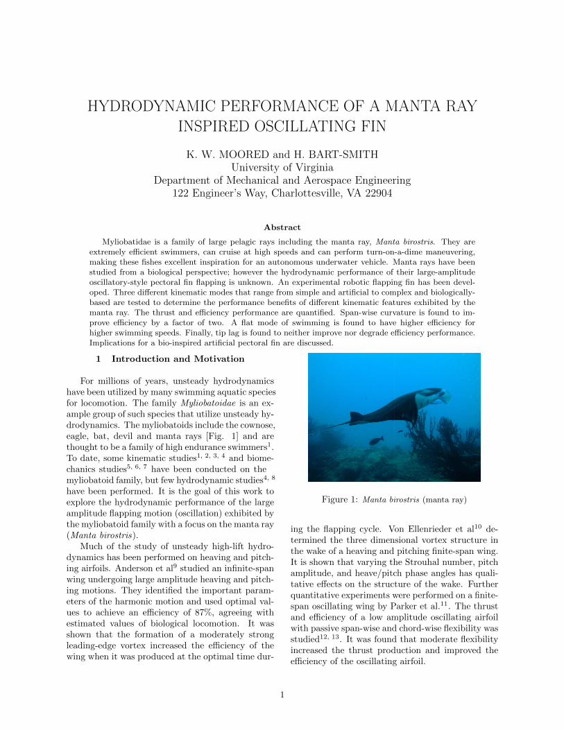
For millions of years, unsteady hydrodynamicshave been utilized by many swimming aquatic speciesfor locomotion. The family Myliobatoidae is an ex-ample group of such species that utilize unsteady hy-drodynamics. The myliobatoids include the cownose,eagle, bat, devil and manta rays [Fig. 1] and arethought to be a family of high endurance swimmers1.To date, some kinematic studies1, 2, 3, 4 and biome-chanics studies5, 6, 7 have been conducted on themyliobatoid family, but few hydrodynamic studies4, 8
have been performed. It is the goal of this work toexplore the hydrodynamic performance of the largeamplitude flapping motion (oscillation) exhibited bythe myliobatoid family with a focus on the manta ray(Manta birostris).
Much of the study of unsteady high-lift hydro-dynamics has been performed on heaving and pitch-ing airfoils. Anderson et al9 studied an infinite-spanwing undergoing large amplitude heaving and pitch-ing motions. They identified the important param-eters of the harmonic motion and used optimal val-ues to achieve an efficiency of 87%, agreeing withestimated values of biological locomotion. It wasshown that the formation of a moderately strongleading-edge vortex increased the efficiency of thewing when it was produced at the optimal time dur-
Figure 1: Manta birostris (manta ray)
ing the flapping cycle. Von Ellenrieder et al10 de-termined the three dimensional vortex structure inthe wake of a heaving and pitching finite-span wing.It is shown that varying the Strouhal number, pitchamplitude, and heave/pitch phase angles has quali-tative effects on the structure of the wake. Furtherquantitative experiments were performed on a finite-span oscillating wing by Parker et al.11. The thrustand efficiency of a low amplitude oscillating airfoilwith passive span-wise and chord-wise flexibility wasstudied12, 13. It was found that moderate flexibilityincreased the thrust production and improved theefficiency of the oscillating airfoil.
1
Although flapping airfoils can model some of thekinematics of biological locomotion many more bio-logically detailed studies have been performed. Light-hill14 gave firm theoretical grounding of the study ofbiological hydrodynamic mechanisms used for propul-sion. He put forth preliminary hydrodynamic mod-els for aguilliform (eel-like) motion and carangiform(fish-like) motion and used the results to show hy-drodynamic advantages to certain biological traitssuch as the lunate tail of many fishes. Lighthill’swork paved the way for numerous studies on thehydrodynamics of fishes and mammals reviewed bymany researchers. Fish and Lauder15 reviewed someof these studies on different biological mechanismsthat give rise to the flow control of vorticity. Tri-antafyllou et al.16 highlighted the research done onunderstanding the hydrodynamics of fish-like swim-ming by reviewing CFD, experimental and theoret-ical fluid dynamics work. Also, Sfakiotakis et al.17
reviewed different fish swimming modes utilizing notonly body and caudal fin undulations, but also pec-toral and median paired fin locomotion and maneu-vering. It is emphasized that pectoral fin locomotioncan have significant advantages in maneuvering andstation-keeping17. In recent years, more attention isbeing paid to pectoral fin hydrodynamics as their im-portance is realized in not only steady-state locomo-tion but also in transient maneuvers18, 19, 18, 20, 21.
Rays take pectoral fin locomotion to an evolu-tionary extreme. Rays have a dorso-ventrally flat-tened body with enlarged pectoral fins that are seam-lessly merged with their body to form a biologi-cal blended wing-body configuration. Even thoughamong rays there is similar morphology, their lo-comotor strategies can be very different. Undula-tory motion defined as having greater than one wavepresent on a fin 1 is one extreme of kinematic motionand was termed ‘rajiform’ by Breder 22. The otherextreme is oscillatory motion defined as having lessthan half of a wave present (flapping) on a fin andwas coined ‘mobuliform’ by Webb23. Although raysexhibit a continuum of kinematic motions betweenthe two extremes1, myliobatoids, the pelagic rays in-cluding manta, eagle, bat and cownose rays, nearlyexclusively utilize oscillatory motion2, 3, 4.
Much research has been done in the biologicalcharacteristics and behaviors of myliobatoids5, 6, 7,but little research has been done in determining thehydrodynamics of myliobatoids flapping motion.Heine4 studied the kinematics and hydrodynamics ofthe cownose ray by videotaping live rays swimmingin a flow tank and analyzing the video. Heine usedthe kinematic data to attempt to determine the fluidforces acting on the rays using quasi-static potential
flow theory, but the results were not in accordancewith the biological data. This negative result showedthat unsteady mechanisms were responsible for thethrust and efficiency of rays.
Oscillatory motion can be described as two cou-pled motions: curved span-wise deformation and achord-wise traveling wave8. Clark and Smits inves-tigated the hydrodynamics of the chord-wise trav-eling waveciteclark2006. To qualitatively determinethe mechanisms at work they performed dye flow vi-sualization around a batoid-inspired undulating finto construct a 3-D wake structure. They furtherquantified the performance of such a fin by measur-ing the efficiency and thrust production as well asdetermining an optimal gait. Their work studiedlow-amplitude undulatory (traveling wave) motionwith no span-wise curvature and determined thatthe mechanism at work was a series of interactingtrailing-edge vortices forming a reverse von Karmanstreet.
To understand what mechanisms myliobatoidsemploy, the work of Clark and Smits8 needs to beextended to account for high-amplitude oscillatory(flapping) motion with significant span-wise curva-ture. This regime is the dominant kinematic regimefor many myliobatoids4. Thus the specific goal ofthis work is to experimentally quantify the perfor-mance of a fin that actively deforms with the mainkinematic feature exhibited by the manta ray: alarge amplitude curved span-wise deformation. Fur-thermore, the effect of tip lag (span-wise phase de-lay) is quantified. Finally, implications are distilledfor the design of a bio-inspired artificial pectoral fin.
2 Experimental Setup and Methods
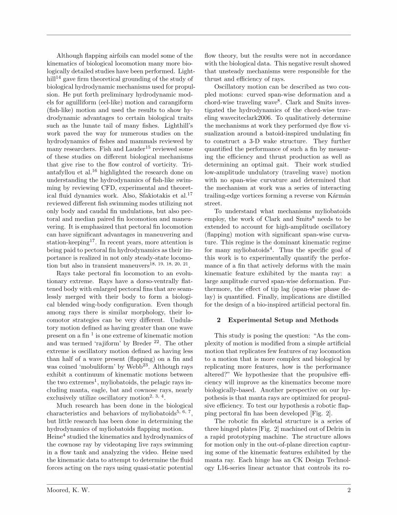
This study is posing the question: “As the com-plexity of motion is modified from a simple artificialmotion that replicates few features of ray locomotionto a motion that is more complex and biological byreplicating more features, how is the performancealtered?” We hypothesize that the propulsive effi-ciency will improve as the kinematics become morebiologically-based. Another perspective on our hy-pothesis is that manta rays are optimized for propul-sive efficiency. To test our hypothesis a robotic flap-ping pectoral fin has been developed [Fig. 2].
The robotic fin skeletal structure is a series ofthree hinged plates [Fig. 2] machined out of Delrin ina rapid prototyping machine. The structure allowsfor motion only in the out-of-plane direction captur-ing some of the kinematic features exhibited by themanta ray. Each hinge has an CK Design Technol-ogy L16-series linear actuator that controls its ro-
Moored, K. W. 2
Figure 2: Artificial pectoral fin composed of three plateshinged together.
tational position. Each actuator is attached to itshinge through a cable-pulley system fabricated outof aluminum 6061 machined hinges, 0.8 mm stainlesssteel wire rope, copper oval crimps, and a pretension-ing idler pulley. Using this cable-pulley system moreadvantageous than embedding the actuators into thefin. First the actuators are out of the potential dan-ger of being flooded by water and do not have tobe waterproofed. Second, moving the actuators outof the fin relieves fin dimension constraints imposedby embedded actuators and reduces the mass thatneeds to be oscillated. The cable emanating fromone side of a hinge is fixed to the front of the actu-ator while the cable emanating from the other sideof the hinge runs over an idler pulley and is fixedto the opposite side of the actuator. This createsan antagonistic relationship between the cables al-lowing for the low-energy rotation of the hinge. Bydisplacing the idler pulley, the antagonistic cablesare pretensioned to ensure smooth actuation.
The actuators are controlled by a PC runningLabVIEW 8.2. The LabVIEW code creates the ac-tuation signal that is sent out through the VISAcommand using RS-232 serial protocol. The serialcommands are received by a Parallax 16 channelservo controller which converts the commands into aPWM signal. The first three channels of the Parallaxcontroller are connected to separate servo motor con-trollers/amplifiers (CK Design Technology, S-series)that condition the signal to be sent directly to theactuators. The Parallax controller sends commandsthrough a single channel at a rate of 38,400 baud cre-
ating a delay between the first channel and the thirdchannel to be approximately 6 ms. This delay is ef-fectively negligible for frequencies up to 1 Hz. TheCK controller also use closed-loop PID control foraccurate positioning of the actuator. Even thoughthe actuators have their own closed-loop controllerthe kinematics of the fin were videotaped for varyingflapping frequencies to ensure that the actual kine-matics matched the prescribed kinematics. This setthe range of possible testing parameters.
The fin skeletal structure is embedded into a com-pliant PVC polymer (M-F Manufacturing, 3 partsplastic stock #2228LP-5 and 1 part plastic softenerstock #4228S). The PVC is molded around the struc-ture into a fin with a trapezoidal planform shapewhich is generic to the myliobatoid family. Thisgeneric shape was chosen instead of the exact plan-form of the manta ray due to fabrication constraintsimposed by the internal structure. The fin has aspan length, b, of 27.92 cm and an average chordlength, c, of 19.05 cm. The cross-sectional shape isa NACA 0020. The trailing edge is stiffened by sheetmetal attached to the skeletal structure.
As described, this simple artificial pectoral fin al-lows for out-of-plane motion with no pitching or un-dulation in the chord direction. The simplest motionachievable by this fin that approximates the motionseen in the manta ray is a flat root-fixed heavingmotion where the fin rotates about the root of thefin. This will be defined as a flat mode of swimming.This mode does not closely resemble the motion ofthe manta ray, but it is simple to design, fabricateand control. To more closely approximate the mo-tion exhibited by the manta ray each plate can be ac-tuated with different angular displacements to createa curved span-wise deformation defined as a curvedmode of swimming. It has been observed that thefins of the manta ray exhibit not only curved span-wise deformation but also span-wise flexibility thatcauses the tip to lag from a perfectly synchronizedcurved deformation. This tip lag is achieved withthe artificial fin by sending a traveling wave downthe span of the fin superposed with the curved de-formation. This motion is defined as a tip lag modeof swimming. Comparing the performance of thesemodes of swimming as the complexity is progres-sively increased from a simple artificial motion (flatmode) to a more complex biological motion (tip lagmode) will allow us to quantify the performance ben-efits of replicating these different features of mantaray kinematics.
Moored, K. W. 3
3 Fluid parameters
There are many performance parameters that canbe measured. The current experimental setup wasdeveloped to measure average net force over a cy-cle (F ) and propulsive efficiency (ηp) for a givenset of kinematic parameters. The fin is mountedon to two frictionless rails that constrain the mo-tion of the fin to the stream-wise direction. Whennet thrust is produced the fin will move forward onthe rails and when net drag is produced the fin willmove backwards on the rails. However, the fin is fur-ther constrained at the root leading-edge by a 5 NOmega tension/compression load cell (LCFA-500g).This load cell constrains the stream-wise motion, butmeasures the net force produced by the fin. The netforce varies in time as the fin goes through a flappingcycle. Thus the average net force over a cycle is ofinterest and is defined below.
F =1
T
∫ T
0
F (t) dt (1)
The period of oscillation, T is equal to the inverseof the frequency, 1/f . The net force can be non-dimensionalized as the coefficient of thrust (cT ) toallow for comparison among fins of different size andin different flow conditions.
cT =F
12ρSU
2(2)
The fluid density (ρ), planform area (S) and thestream-wise flow velocity (U) all combine to non-dimensionalize the average net force. The averagepower input by the fin into the fluid (Pf ) must bemeasured. The average power over a cycle is definedas the following.
Pf =1
T
∫ T
0
P (t) dt (3)
Similar to the average force, the average powercan be non-dimensionalized for comparison amongdifferent fins and different flow conditions.
cP =Pf
12ρSU
3(4)
The time-varying power is equal to the innerproduct of the lift force along the span of the finand the fin flapping velocity along the span, P (t) =∫ b
0L (y, t)
Tv (y, t) dy. The lift force on the fin is the
force acting on the fin in the direction perpendicu-lar to the stream-wise direction. Although the liftforce along the span could be measured to calculate
the power input, this is difficult to physically imple-ment. Instead the electrical power supplied to theactuators is directly measured.
Pa (t) = I (t)V (t) (5)
The current is measured with a hall effect sen-sor while the voltage is split with a voltage dividerand the reduced voltage is monitored by the DAQcard. To calculate the power input to the fluid thedifference between the power supplied to the fin inair must be subtracted from the power supplied tothe fin in water to normalize out the power sup-plied to move the fin itself. Furthermore, their isan efficiency drop across the actuators that must beapplied. Thus the full equation of the power inputto the fluid from all three sections of the fin is thefollowing.
Pf =(ηrPr + ηcPc + ηtPt
)wat
−(ηrPr + ηcPc + ηtPt
)air
(6)
The actuator efficiency for the root, center andtip sections is ηr, ηc and ηt respectively. The averageelectrical power to root, center and tip sections isPr, Pc and Pt respectively. The actuator efficiencieswere measured to be between 1% and 10% efficientover the operating range. The actuator efficiencyvaries depending on the electrical power supplied tothe actuator (dependent on load and speed of theactuator) and the speed of the actuator. Thus a setof efficiency data for each actuator was measuredand a surface was interpolated for the independentparameters Pa and va.
Lastly, the Froude propulsive efficiency can becalculated by combining the force and power mea-surements.
ηp =FU
Pf=cTcP
(7)
The fin structure embedded in PVC is fixed toa carriage that is towed along two Λ-shaped trackmounted on aluminum I-beams spanning the 5 m (L)by 1.52 m (W) by 0.91 m (D) tow tank. A motorat one end of the tank pulls a roller chain that isattached to the carriage at speeds up to 1 m/s. Thistow velocity sets the stream-wise velocity, U . Thestream-wise velocity is set by the choice of Reynold’snumber.
Re =Uc
ν(8)
The kinematic viscosity, ν, for water is 1.12 ×10⁻⁶ m2/s. The maximum tip amplitude measuredfrom the neutral plane, A, is determined from thenon-dimensional tip amplitude exhibited by the
Moored, K. W. 4

manta ray, A/b = 0.44. The curvature along thespan exhibited by the manta ray is also matched forthe curved and tip lag modes of swimming. Once thestream-wise velocity and the amplitude of motionare set, the frequency of motion is determined bythe choice of the Strouhal number.
St =fA
U(9)
The average amplitude, A = A/2, is a commonapproximation of the average wake width for a span-wise varying amplitude.
4 Results and Discussion
To collect data the fin was towed down the tankat a set Re of 25,000, non dimensional amplitude of0.44 and mode shape while the St was varied over arange of 0.15-0.45 by increments of 0.025 for 13 testsover the testing range. At each testing parameterthe maximum number of cycles was used to averagethe force and power data over multiple cycles. Eachtesting parameter was repeated five times in waterand six times in air for a total of 163 tests per setof data. The reported values are the mean valuesof those tests and the reported error is the standarderror of the mean for the tests. For the four sets ofreported data a total of 652 tests were performed.
4.1 Flat Mode versus Curved Mode
The first two modes of swimming that are com-pared are the flat mode and the curved mode. Figure[3] shows the coefficient of thrust as the St is var-ied. There is an increase in the amount of thrustproduced as the frequency increases as would be ex-pected. The coefficient of thrust for the curved modeis higher than the flat mode for low St, but theyquickly cross over and the flat mode produces muchmore thrust at higher St.
Figure [4] shows the coefficient of power as theSt is varied. It can be seen that the power alsoincreases with increasing frequency as would be ex-pected. However, over the St range the coefficientof power is always lower for the curved mode thanthe flat mode. Both of the power coefficients tendto zero at the low St range.
Since the two modes of swimming input differ-ent amounts of power into the fluid the appropriatethrust performance comparison will match power co-efficients instead of St. Figure [5] shows the thrustcoefficient compared to the power coefficient for thetwo modes of swimming. Both modes show that asthe power input is increased the thrust is increased,
but the at the higher input powers it takes moreand more additional power to achieve an equivalentchange in thrust at the lower power inputs. For lowerpower inputs, a given amount of power will producemore thrust for the curved mode of swimming. Athigher power inputs, a given amount of power willproduce more thrust for the flat mode of swimming.At a power coefficient of 2.75 there is a transition.This transition can be viewed as a point where morethrust output can be achieved for a given amountof power by changing gaits of the curved mode tothe flat mode. As the power to the fluid is increasedthe thrust output is increased which would lead to,for a free-swimming fin, a higher swimming velocity.This gait transition relates to a specific swimmingspeed at which to make the transition. Thus forlower swimming speeds the curved motion is moreefficient while at higher speeds the flat mode is moreefficient.
0.1 0.15 0.2 0.25 0.3 0.35 0.4 0.45 0.5−0.1
0
0.1
0.2
0.3
0.4
0.5
0.6Thrust Performance, h/b = 0.44, Re = 25000
St
CT
Flat
Curved
Figure 3: Thrust performance as a function of St.
0.1 0.15 0.2 0.25 0.3 0.35 0.4 0.45 0.50
1
2
3
4
5
6
7
8
9Thrust Performance, h/b = 0.44, Re = 25000
St
CP
Flat
Curved
Figure 4: Coefficient of power as a function of St.
Figure [6] shows the propulsive efficiency plottedagainst the St. The efficiencies have a quick rise atthe lower St, a peak in efficiency and then a slow
Moored, K. W. 5

0 1 2 3 4 5 6 7 8 9−0.1
0
0.1
0.2
0.3
0.4
0.5
0.6
0.7Thrust Performance, h/b = 0.44, Re = 25000
CP
CT
Flat
Curved
Gait Transition
swimmingV
Figure 5: Thrust performance as a function of inputpower coefficient
decline in efficiency at the higher St. This trendis characteristic of the efficiency curves for oscillat-ing foils8, 9, 12, 13, 24. The peak efficiency for the flatmode is 9.5% and occurs at a St = 0.3. The peakefficiency for the curved mode is 19.7% and occursat a St = 0.2. Both of the peak efficiencies fall inthe range 0.2 < St < 0.4 which is the St where mostswimming and flying species cruise25. Even thoughthere are two regimes where each mode of swimmingis more efficient, the curved mode of swimming isseen to have a higher peak efficiency. The efficiencyis improved by about a factor of two.
0.1 0.15 0.2 0.25 0.3 0.35 0.4 0.45 0.5 0.550
0.05
0.1
0.15
0.2
0.25
0.3
0.35
0.4
0.45
0.5Efficiency Performance, h/b = 0.44, Re = 25000
S t
PropulsiveEfficiency,η
Fla t
Curved
Peak Efficiency = 19.7%
Peak Efficiency = 9.5%
Figure 6: Efficiency performance as a function of St.
4.2 Curved Mode versus Tip Lag Mode
The second two modes of swimming that arecompared are the curved mode and the tip lag mode.The degree of tip lag is reported as the tip deflec-tion normalized by the span as the fin root sectioncrosses the neutral plane. When there is no tip lagpresent the entire span crosses the neutral plane atthe same time. Figure [7] shows the two tested tip
lags (3.2% and 11.3%) compared to the curved modeof swimming (0%).
Δz/b = 0% Δz/b = 3.2% Δz/b = 11.3%
Figure 7: Varying tip lags used for testing.
Figure [8] shows the thrust coefficient due to avariation in the St. As the amount of tip lag is in-creased there is a slight increase in the amount ofthrust produced. Figure [9] shows the power coef-ficient due to a variation in the St. It can be seenthat at low St the power coefficients are about thesame, then at higher power coefficients they deviatefrom each other with 3.2% inputting the most powerand 11.3% inputting the least power.
0.1 0.15 0.2 0.25 0.3 0.35 0.4 0.45 0.50
0.05
0.1
0.15
0.2
0.25
0.3
0.35Thrust Performance, h/b = 0.44, Re = 25000
St
CT
0%
3 .2%
11.3%
Figure 8: Thrust performance as a function of St.
Figure [10] shows the efficiency curves for thecurved mode and the tip lag mode as a function ofSt. It can be seen that the peak of efficiency for11.3% tip lag is broadened out. Also the efficienciesat higher St are improved for 11.3% tip lag. How-ever, Figure [11] plots the peak efficiencies based onthe amount of tip lag, which shows that there isneither an improvement nor a degradation in the ef-ficiency performance between the curved mode andthe tip lag mode. This suggests that the tip lag
Moored, K. W. 6

0.1 0.15 0.2 0.25 0.3 0.35 0.4 0.45 0.50
1
2
3
4
5
6Thrust Performance, h/b = 0.44, Re = 25000
St
CP
0%
3 .2%
11.3%
Figure 9: Power coefficient as a function of St.
observed in the manta ray might be present due tothe finite stiffness of biological materials combinedwith the fact that the efficiency performance is notdegraded by incorporating some amount of tip lag.
0.1 0.15 0.2 0.25 0.3 0.35 0.4 0.45 0.5 0.550
0.1
0.2
0.3
0.4
0.5
0.6
Efficiency Performance, h/b = 0.44, Re = 25000
S t
PropulsiveEfficiency,η
0%
3.2%
11.3%
Figure 10: Efficiency performance as a function of St.
5 Conclusions
This study has explored three kinematic modesof swimming (flat, curved and tip lag). Going fromthe simple mode of swimming (flat) to the morecomplex and biologically similar mode of swimming(tip lag) the thrust and efficiency performance werequantified. By comparing these modes of swimmingthe following implications for a bio-inspired artificialpectoral fin have been distilled:
1. Including span-wise curvature significantly im-proves efficiency performance and should bedesigned into an artificial pectoral fin.
2. The flat mode of swimming can be utilizedat higher swimming speeds to maximize effi-
0 2 4 6 8 10 120
0.05
0.1
0.15
0.2
0.25
0.3
0.35
0.4
0.45
0.5Phas e Delay Dependence, h/b = 0.44, Re = 25000
∆z/b, %
η
Figure 11: Efficiency performance dependence on tiplag.
ciency. This mode of swimming would be ap-propriate for escape scenarios.
3. A span-wise traveling wave does not improveor degrade the efficiency performance and there-fore does not need to be designed into an arti-ficial fin.
Future research will performing dye flow visual-ization and PIV measurements to quantify the flowfeatures that produce the differences in performance.Moreover, the incorporation of a undulatory compo-nent in the chord-wise direction will be quantified.
6 Acknowledgements
The authors would like to acknowledge fundingfrom the Office of Naval Research through the MURIprogram on Biologically-Inspired Autonomous SeaVehicles (Contract No. N00014-08-1-0642), the Davidand Lucille Packard Foundation, the National Sci-ence Foundation (Contract No. CMS-0384884), andthe Virginia Space Grant Consortium.
References
1 L. J. Rosenberger, Pectoral fin locomotion in ba-toid fishes: undulation versus oscillation, Journalof Experimental Biology 204 (2) (2001) 379–394.
2 W. Klausewitz, Der lokomotionsmodus derflugelrochen (myliobatoidei), Zool. Anz 173.
3 D. E. Sasko, M. N. Dean, P. J. Motta, R. E.Hueter, Prey capture behavior and kinematics ofthe atlantic cownose ray, rhinoptera bonasus, Zo-ology 109 (3) (2006) 171–181.
Moored, K. W. 7
4 C. Heine, Mechanics of flapping fin locomotionin the cownose ray, rhinoptera bonasus (elasmo-branchii, myliobatidae)., Ph.D. thesis, Duke Uni-versity (1992).
5 J. T. Schaefer, A. P. Summers, Batoid wing skele-tal structure: Novel morphologies, mechanicalimplications, and phylogenetic patterns, Journalof Morphology 264 (3) (2005) 298–313.
6 M. N. Dean, J. J. Bizzarro, A. P. Summers,The evolution of cranial design, diet, and feed-ing mechanisms in batoid fishes, Integrative andComparative Biology 47 (1) (2007) 70.
7 A. Summers, Stiffening the stingray skeleton-an investigation of durophagy in myliobatidstingrays (chondrichthyes, batoidea, myliobati-dae), Journal of Morphology 243 (2) (2000) 113–126.
8 R. P. Clark, A. J. Smits, Thrust production andwake structure of a batoid-inspired oscillating fin,Journal of Fluid Mechanics 562 (2006) 415–429.
9 J. M. Anderson, K. Streitlien, D. S. Barrett, M. S.Triantafyllou, Oscillating foils of high propulsiveefficiency, Journal of Fluid Mechanics 360 (1998)41–72.
10 K. D. Von Ellenrieder, K. Parker, J. Soria, Flowstructures behind a heaving and pitching finite-span wing, Journal of Fluid Mechanics 490 (2003)129–138.
11 K. Parker, K. D. Ellenrieder, J. Soria, Usingstereo multigrid dpiv (smdpiv) measurements toinvestigate the vortical skeleton behind a finite-span flapping wing, Experiments in Fluids 39 (2)(2005) 281–298.
12 S. Heathcote, I. Gursul, Flexible flapping airfoilpropulsion at low reynolds numbers, AIAA jour-nal 45 (5) (2007) 1066–1079.
13 S. Heathcote, Z. Wang, I. Gursul, Effect of span-wise flexibility on flapping wing propulsion, Jour-nal of Fluids and Structures 24 (2) (2008) 183–199.
14 M. J. Lighthill, Aquatic animal propulsion of highhydromechanical efficiency, Journal of Fluid Me-chanics Digital Archive 44 (02) (2006) 265–301.
15 F. E. Fish, G. V. Lauder, Passive and active flowcontrol by swimming fishes and mammals, Ann.Rev. Fluid Mech 38.
16 M. S. Triantafyllou, G. S. Triantafyllou, D. K. P.Yue, Hydrodynamics of fishlike swimming, An-nual Review of Fluid Mechanics 32 (1) (2000)33–53.
17 M. Sfakiotakis, D. M. Lane, J. B. C. Davies, Re-view of fish swimming modes for aquatic locomo-tion, IEEE Journal of Oceanic Engineering 24 (2)(1999) 237–252.
18 G. V. Lauder, J. C. Nauen, E. G. Drucker, Exper-imental hydrodynamics and evolution: Functionof median fins in ray-finned fishes 1 (2002).
19 S. A. Combes, T. L. Daniel, Shape, flapping andflexion: wing and fin design for forward flight,Journal of Experimental Biology 204 (12) (2001)2073–2085.
20 J. Palmisano, R. Ramamurti, K. J. Lu, J. Co-hen, W. Sandberg, B. Ratna, Design of abiomimetic controlled-curvature robotic pectoralfin, Robotics and Automation, 2007 IEEE Inter-national Conference on (2007) 966–973.
21 P. R. Bandyopadhyay, Trends in biorobotic au-tonomous undersea vehicles, IEEE Journal ofOceanic Engineering 30 (1) (2005) 109–139.
22 C. M. Breder, The locomotion of fishes, New YorkZoological Society, New York.
23 P. W. Webb, The biology of fish swimming, no.45-62, Cambridge University Press, 1994.
24 J. H. J. Buchholz, A. J. Smits, On the evolutionof the wake structure produced by a low-aspect-ratio pitching panel, Journal of Fluid Mechanics546 (2005) 433–443.
25 G. Taylor, R. Nudds, A. Thomas, Flying andswimming animals cruise at a strouhal numbertuned for high power efficiency, Nature 425 (6959)(2003) 707–711.
Moored, K. W. 8