how to use this install guide -...
TRANSCRIPT
NOTICE: Automotive Data Solutions Inc. (ADS) recommends having this installation performed by a certifi ed technician. Logos and trademarks used here in are the properties of their respective owners.
WARNINGPressing the printer icon or “quick printing” this document will print
all of the guides in this compilation.
Open the Bookmarks menu and find your vehicle OR scroll down until you find the install guide for your vehicle.
Print only the pages for your vehicle using the advanced options in the Print menu.
Install your Maestro RR according to the guide for your vehicle.
HOW TO USE THIS INSTALL GUIDE1
2
3
SELECT VEHICLE PRINT PAGES NEEDED

PROGRAMMED FIRMWAREADS-RR(SR)-SUB02B-DS
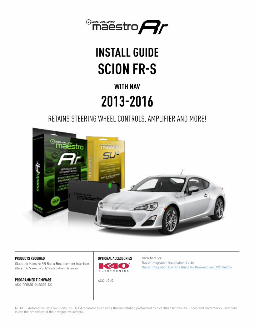
PRODUCTS REQUIREDiDatalink Maestro RR Radio Replacement InterfaceiDatalink Maestro SU2 Installation Harness
OPTIONAL ACCESSORIES
ACC-uSU2
Click here for: Radar Integration Installation GuideRadar Integration Owner’s Guide for Kenwood and JVC Radios
E L E C T R O N I C S
INSTALL GUIDESCION FR-S
BASE
2013-2016Retains steeRing wheel contRols, amplifieR and moRe!
NOTICE: Automotive Data Solutions Inc. (ADS) recommends having this installation performed by a certified technician. Logos and trademarks used here in are the properties of their respective owners.

ADS-RR(SR)-SUB02B-DS maestro.idatalink.com
scion fR-s Base 2013-2016
Automotive Data Solutions Inc. © 2018 2
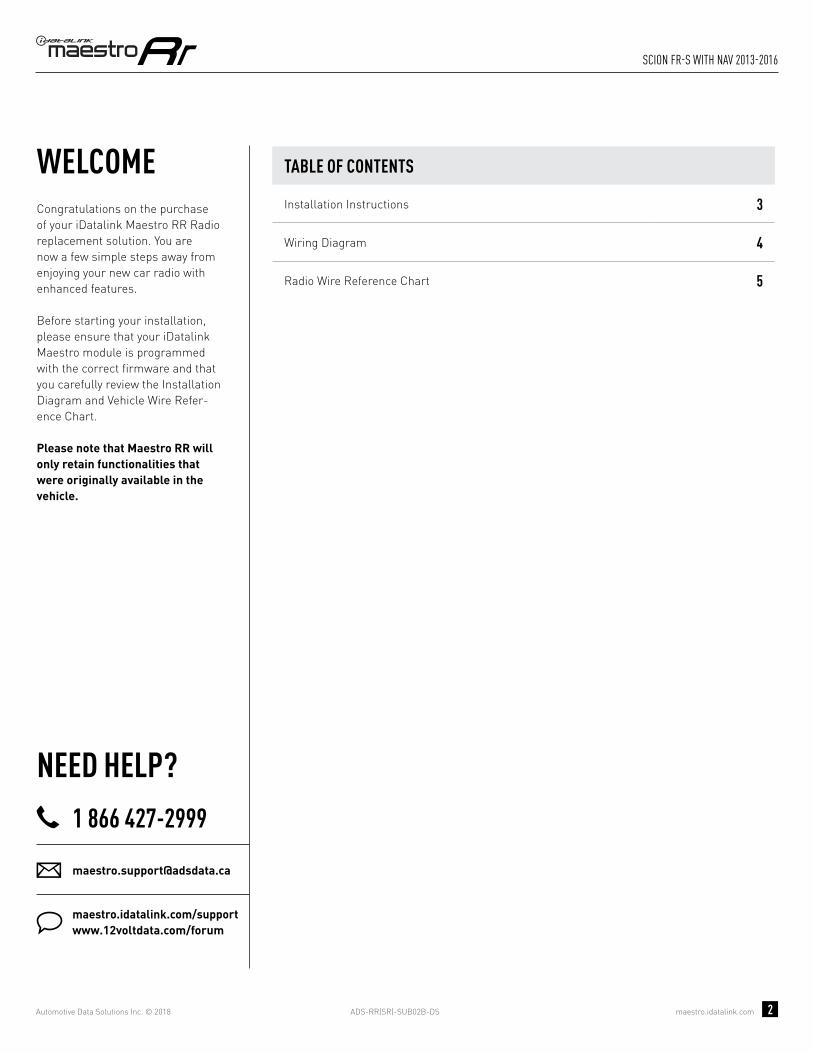
WELCOME
NEED hELP?
Congratulations on the purchase of your iDatalink Maestro RR Radio replacement solution. You are now a few simple steps away from enjoying your new car radio with enhanced features. Before starting your installation, please ensure that your iDatalink Maestro module is programmed with the correct fi rmware and that you carefully review the Installation Diagram and Vehicle Wire Refer-ence Chart.
Please note that Maestro RR will only retain functionalities that were originally available in the vehicle.
1 866 427-2999
maestro.idatalink.com/supportwww.12voltdata.com/forum
TABLE OF CONTENTS
Installation Instructions 3
Wiring Diagram 4
Radio Wire Reference Chart 5

ADS-RR(SR)-SUB02B-DS maestro.idatalink.com
scion fR-s Base 2013-2016
Automotive Data Solutions Inc. © 2018 3
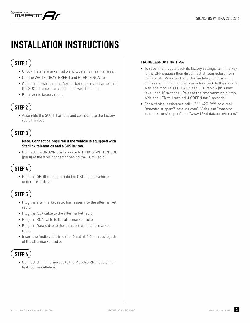
INSTALLATION INSTRUCTIONS STEP 1
• Unbox the aftermarket radio and locate its main harness.
• Cut the WHITE, GRAY, GREEN and PURPLE RCA tips.
• Connect the wires from aftermarket radio main harness to the SU2 T-harness and match the wire functions.
• Remove the factory radio.
STEP 2
• Assemble the SU2 T-harness and connect it to the factory radio harness.
STEP 3Note: Connection required if the vehicle is equipped with Starlink telematics and a SOS button.
• Connect the BROWN Starlink wire to PINK or WHITE/BLUE (pin 8) of the 8 pin connector behind the OEM Radio.
STEP 4• Plug the OBDII connector into the OBDII of the vehicle,
under driver dash.
STEP 5• Plug the aftermarket radio harnesses into the aftermarket
radio.
• Plug the AUX cable to the aftermarket radio.
• Plug the RCA cable to the aftermarket radio.
• Plug the Data cable to the data port of the aftermarket radio.
• Insert the Audio cable into the iDatalink 3.5 mm audio jack of the aftermarket radio.
STEP 6• Connect all the harnesses to the Maestro RR module then
test your installation.
TROUBLESHOOTING TIPS:
• To reset the module back its factory settings, turn the key to the OFF position then disconnect all connectors from the module. Press and hold the module’s programming button and connect all the connectors back to the module. Wait, the module’s LED will fl ash RED rapidly (this may take up to 10 seconds). Release the programming button. Wait, the LED will turn solid GREEN for 2 seconds.
• For technical assistance call 1-866-427-2999 or e-mail “[email protected]”. Visit us at “maestro.idatalink.com/support” and “www.12voltdata.com/forum/”
4
ADS-RR(SR)-SUB02B-DS maestro.idatalink.com
scion fR-s Base 2013-2016
Automotive Data Solutions Inc. © 2018 4
4
BACKUP CAMBACKUP CAMCC
AUXAUX
AA
D
BB
MAESTRO RR MODULE
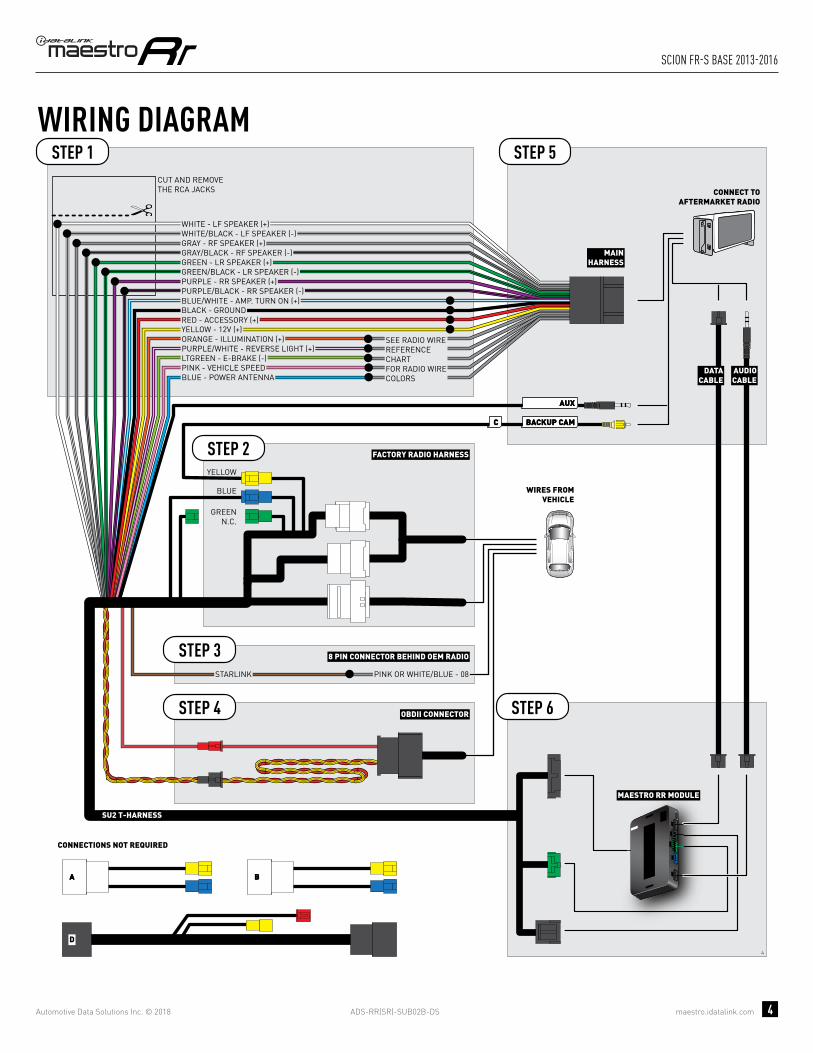
CUT AND REMOVE THE RCA JACKS
STEP 1
MAINHARNESS
SU2 T-HARNESS
WHITE - LF SPEAKER (+)WHITE/BLACK - LF SPEAKER (-)GRAY - RF SPEAKER (+)GRAY/BLACK - RF SPEAKER (-)GREEN - LR SPEAKER (+)GREEN/BLACK - LR SPEAKER (-)
PURPLE/BLACK - RR SPEAKER (-)
YELLOW - 12V (+)
BLACK - GROUNDRED - ACCESSORY (+)
BLUE/WHITE - AMP. TURN ON (+)
PURPLE - RR SPEAKER (+)
STEP 5
STEP 6
ORANGE - ILLUMINATION (+)PURPLE/WHITE - REVERSE LIGHT (+)LTGREEN - E-BRAKE (-)
BLUE - POWER ANTENNAPINK - VEHICLE SPEED
WIRING DIAGRAM
WIRES FROMVEHICLE
FACTORY RADIO HARNESSSTEP 2
STEP 4 OBDII CONNECTOR
SEE RADIO WIREREFERENCECHARTFOR RADIO WIRECOLORS
DATACABLE
AUDIOCABLE
CONNECT TOAFTERMARKET RADIO
BLUE
GREENN.C.
CONNECTIONS NOT REQUIRED
YELLOW
STARLINK PINK OR WHITE/BLUE - 08
8 PIN CONNECTOR BEHIND OEM RADIOSTEP 3

ADS-RR(SR)-SUB02B-DS maestro.idatalink.com
scion fR-s Base 2013-2016
Automotive Data Solutions Inc. © 2018 5
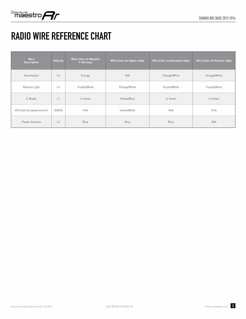
RADIO WIRE REFERENCE CHART
WireDescription Polarity Wire Color on Maestro
T-Harness Wire Color on Alpine cable Wire Color on Kenwood cable Wire Color on Pioneer cable
Illumination (+) Orange N/A Orange/White Orange/White
Reverse Light (+) Purple/White Orange/White Purple/White Purple/White
E-Brake (-) Lt Green Yellow/Blue Lt Green Lt Green
VSS (vehicle speed sensor) (DATA) Pink Green/White N/A Pink
Power Antenna (+) Blue Blue Blue N/A

PROGRAMMED FIRMWAREADS-RR(SR)-SUB02B-DS
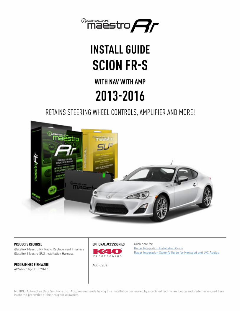
PRODUCTS REQUIREDiDatalink Maestro RR Radio Replacement InterfaceiDatalink Maestro SU2 Installation Harness
OPTIONAL ACCESSORIES
ACC-uSU2
Click here for: Radar Integration Installation GuideRadar Integration Owner’s Guide for Kenwood and JVC Radios
E L E C T R O N I C S
INSTALL GUIDESCION FR-S
WITh AMP
2013-2016Retains steeRing wheel contRols, amplifieR and moRe!
NOTICE: Automotive Data Solutions Inc. (ADS) recommends having this installation performed by a certified technician. Logos and trademarks used here in are the properties of their respective owners.

ADS-RR(SR)-SUB02B-DS maestro.idatalink.com
scion fR-s with amp 2013-2016
Automotive Data Solutions Inc. © 2018 2
WELCOME
NEED hELP?
Congratulations on the purchase of your iDatalink Maestro RR Radio replacement solution. You are now a few simple steps away from enjoying your new car radio with enhanced features. Before starting your installation, please ensure that your iDatalink Maestro module is programmed with the correct fi rmware and that you carefully review the Installation Diagram and Vehicle Wire Refer-ence Chart.
Please note that Maestro RR will only retain functionalities that were originally available in the vehicle.
1 866 427-2999
maestro.idatalink.com/supportwww.12voltdata.com/forum
TABLE OF CONTENTS
Installation Instructions 3
Wiring Diagram 4
Radio Wire Reference Chart 5
ADS-RR(SR)-SUB02B-DS maestro.idatalink.com
scion fR-s with amp 2013-2016
Automotive Data Solutions Inc. © 2018 3
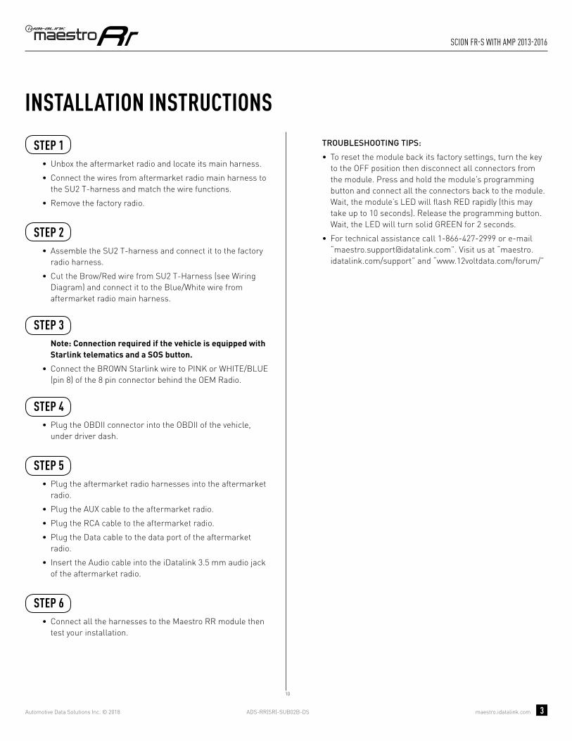
INSTALLATION INSTRUCTIONS STEP 1
• Unbox the aftermarket radio and locate its main harness.
• Connect the wires from aftermarket radio main harness to the SU2 T-harness and match the wire functions.
• Remove the factory radio.
STEP 2
• Assemble the SU2 T-harness and connect it to the factory radio harness.
• Cut the Brow/Red wire from SU2 T-Harness (see Wiring Diagram) and connect it to the Blue/White wire from aftermarket radio main harness.
STEP 3Note: Connection required if the vehicle is equipped with Starlink telematics and a SOS button.
• Connect the BROWN Starlink wire to PINK or WHITE/BLUE (pin 8) of the 8 pin connector behind the OEM Radio.
STEP 4• Plug the OBDII connector into the OBDII of the vehicle,
under driver dash.
STEP 5• Plug the aftermarket radio harnesses into the aftermarket
radio.
• Plug the AUX cable to the aftermarket radio.
• Plug the RCA cable to the aftermarket radio.
• Plug the Data cable to the data port of the aftermarket radio.
• Insert the Audio cable into the iDatalink 3.5 mm audio jack of the aftermarket radio.
STEP 6• Connect all the harnesses to the Maestro RR module then
test your installation.
TROUBLESHOOTING TIPS:
• To reset the module back its factory settings, turn the key to the OFF position then disconnect all connectors from the module. Press and hold the module’s programming button and connect all the connectors back to the module. Wait, the module’s LED will fl ash RED rapidly (this may take up to 10 seconds). Release the programming button. Wait, the LED will turn solid GREEN for 2 seconds.
• For technical assistance call 1-866-427-2999 or e-mail “[email protected]”. Visit us at “maestro.idatalink.com/support” and “www.12voltdata.com/forum/”
10
ADS-RR(SR)-SUB02B-DS maestro.idatalink.com
scion fR-s with amp 2013-2016
Automotive Data Solutions Inc. © 2018 4
10
BACKUP CAMBACKUP CAMCC
AUXAUX
AA
D
BB
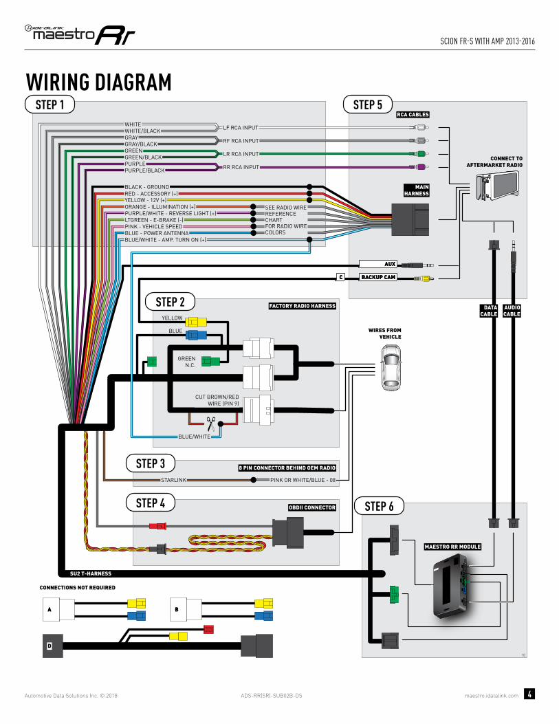
STARLINK PINK OR WHITE/BLUE - 08
8 PIN CONNECTOR BEHIND OEM RADIOSTEP 3
MAESTRO RR MODULE
STEP 1
SU2 T-HARNESS
STEP 5
STEP 6
WIRING DIAGRAM
WIRES FROMVEHICLE
FACTORY RADIO HARNESSSTEP 2
STEP 4 OBDII CONNECTOR
DATACABLE
AUDIOCABLE
CONNECT TOAFTERMARKET RADIO
BLUE
CONNECTIONS NOT REQUIRED
YELLOW
MAINHARNESS
YELLOW - 12V (+)
BLACK - GROUNDRED - ACCESSORY (+)
ORANGE - ILLUMINATION (+)PURPLE/WHITE - REVERSE LIGHT (+)LTGREEN - E-BRAKE (-)
BLUE - POWER ANTENNAPINK - VEHICLE SPEED
WHITEWHITE/BLACKGRAYGRAY/BLACKGREENGREEN/BLACK
PURPLE/BLACKPURPLE
LF RCA INPUT
RF RCA INPUT
LR RCA INPUT
RR RCA INPUT
RCA CABLES
GREENN.C.
CUT BROWN/REDWIRE (PIN 9)
CUT BROWN/REDWIRE (PIN 9)
BLUE/WHITE - AMP. TURN ON (+)
SEE RADIO WIREREFERENCECHARTFOR RADIO WIRECOLORS
BLUE/WHITEBLUE/WHITE

ADS-RR(SR)-SUB02B-DS maestro.idatalink.com
scion fR-s with amp 2013-2016
Automotive Data Solutions Inc. © 2018 5
RADIO WIRE REFERENCE CHART
WireDescription Polarity Wire Color on Maestro
T-Harness Wire Color on Alpine cable Wire Color on Kenwood cable Wire Color on Pioneer cable
Illumination (+) Orange N/A Orange/White Orange/White
Reverse Light (+) Purple/White Orange/White Purple/White Purple/White
E-Brake (-) Lt Green Yellow/Blue Lt Green Lt Green
VSS (vehicle speed sensor) (DATA) Pink Green/White N/A Pink
Power Antenna (+) Blue Blue Blue N/A
PROGRAMMED FIRMWAREADS-RR(SR)-SUB02B-DS
PRODUCTS REQUIREDiDatalink Maestro RR Radio Replacement InterfaceiDatalink Maestro SU2 Installation Harness
OPTIONAL ACCESSORIES
ACC-uSU2
Click here for: Radar Integration Installation GuideRadar Integration Owner’s Guide for Kenwood and JVC Radios
E L E C T R O N I C S
INSTALL GUIDESCION FR-S
WITh NAV
2013-2016Retains steeRing wheel contRols, amplifieR and moRe!
NOTICE: Automotive Data Solutions Inc. (ADS) recommends having this installation performed by a certified technician. Logos and trademarks used here in are the properties of their respective owners.
ADS-RR(SR)-SUB02B-DS maestro.idatalink.com
scion fR-s with naV 2013-2016
Automotive Data Solutions Inc. © 2018 2
WELCOME
NEED hELP?
Congratulations on the purchase of your iDatalink Maestro RR Radio replacement solution. You are now a few simple steps away from enjoying your new car radio with enhanced features. Before starting your installation, please ensure that your iDatalink Maestro module is programmed with the correct fi rmware and that you carefully review the Installation Diagram and Vehicle Wire Refer-ence Chart.
Please note that Maestro RR will only retain functionalities that were originally available in the vehicle.
1 866 427-2999
maestro.idatalink.com/supportwww.12voltdata.com/forum
TABLE OF CONTENTS
Installation Instructions 3
Wiring Diagram 4
Radio Wire Reference Chart 5

ADS-RR(SR)-SUB02B-DS maestro.idatalink.com
scion fR-s with naV 2013-2016
Automotive Data Solutions Inc. © 2018 3
INSTALLATION INSTRUCTIONS STEP 1
• Unbox the aftermarket radio and locate its main harness.
• Cut the WHITE, GRAY, GREEN and PURPLE RCA tips.
• Connect the wires from aftermarket radio main harness to the SU2 T-harness and match the wire functions.
• Remove the factory radio.
STEP 2
• Assemble the SU2 T-harness and connect it to the factory radio harness.
STEP 3Note: Connection required if the vehicle is equipped with Starlink telematics and a SOS button.
• Connect the BROWN Starlink wire to PINK or WHITE/BLUE (pin 8) of the 8 pin connector behind the OEM Radio.
STEP 4• Plug the OBDII connector into the OBDII of the vehicle,
under driver dash.
STEP 5• Plug the aftermarket radio harnesses into the aftermarket
radio.
• Plug the AUX cable to the aftermarket radio.
• Plug the RCA cable to the aftermarket radio.
• Plug the Data cable to the data port of the aftermarket radio.
• Insert the Audio cable into the iDatalink 3.5 mm audio jack of the aftermarket radio.
STEP 6• Connect all the harnesses to the Maestro RR module then
test your installation.
TROUBLESHOOTING TIPS:
• To reset the module back its factory settings, turn the key to the OFF position then disconnect all connectors from the module. Press and hold the module’s programming button and connect all the connectors back to the module. Wait, the module’s LED will fl ash RED rapidly (this may take up to 10 seconds). Release the programming button. Wait, the LED will turn solid GREEN for 2 seconds.
• For technical assistance call 1-866-427-2999 or e-mail “[email protected]”. Visit us at “maestro.idatalink.com/support” and “www.12voltdata.com/forum/”
9

ADS-RR(SR)-SUB02B-DS maestro.idatalink.com
scion fR-s with naV 2013-2016
Automotive Data Solutions Inc. © 2018 4
BB
9
BACKUP CAMBACKUP CAMCC
AUXAUX
AA
D
GREENN.C.
MAESTRO RR MODULE
CUT AND REMOVE THE RCA JACKS
STEP 1
MAINHARNESS
SU2 T-HARNESS
WHITE - LF SPEAKER (+)WHITE/BLACK - LF SPEAKER (-)GRAY - RF SPEAKER (+)GRAY/BLACK - RF SPEAKER (-)GREEN - LR SPEAKER (+)GREEN/BLACK - LR SPEAKER (-)
PURPLE/BLACK - RR SPEAKER (-)
YELLOW - 12V (+)
BLACK - GROUNDRED - ACCESSORY (+)
BLUE/WHITE - AMP. TURN ON (+)
PURPLE - RR SPEAKER (+)
STEP 5
STEP 6
ORANGE - ILLUMINATION (+)PURPLE/WHITE - REVERSE LIGHT (+)LTGREEN - E-BRAKE (-)
BLUE - POWER ANTENNA
STARLINK PINK OR WHITE/BLUE - 08
PINK - VEHICLE SPEED
WIRING DIAGRAM
WIRES FROMVEHICLE
FACTORY RADIO HARNESS
8 PIN CONNECTOR BEHIND OEM RADIO
STEP 2
STEP 4
STEP 3
OBDII CONNECTOR
SEE RADIO WIREREFERENCECHARTFOR RADIO WIRECOLORS
DATACABLE
AUDIOCABLE
CONNECT TOAFTERMARKET RADIO
CONNECTIONS NOT REQUIRED
BLUE
NC
NC
YELLOW

ADS-RR(SR)-SUB02B-DS maestro.idatalink.com
scion fR-s with naV 2013-2016
Automotive Data Solutions Inc. © 2018 5
RADIO WIRE REFERENCE CHART
WireDescription Polarity Wire Color on Maestro
T-Harness Wire Color on Alpine cable Wire Color on Kenwood cable Wire Color on Pioneer cable
Illumination (+) Orange N/A Orange/White Orange/White
Reverse Light (+) Purple/White Orange/White Purple/White Purple/White
E-Brake (-) Lt Green Yellow/Blue Lt Green Lt Green
VSS (vehicle speed sensor) (DATA) Pink Green/White N/A Pink
Power Antenna (+) Blue Blue Blue N/A
PROGRAMMED FIRMWAREADS-RR(SR)-SUB02B-DS
PRODUCTS REQUIREDiDatalink Maestro RR Radio Replacement InterfaceiDatalink Maestro SU2 Installation Harness
OPTIONAL ACCESSORIES
ACC-uSU2
Click here for: Radar Integration Installation GuideRadar Integration Owner’s Guide for Kenwood and JVC Radios
E L E C T R O N I C S
INSTALL GUIDESCION FR-SWITh NAV WITh AMP
2013-2016Retains steeRing wheel contRols, amplifieR and moRe!
NOTICE: Automotive Data Solutions Inc. (ADS) recommends having this installation performed by a certified technician. Logos and trademarks used here in are the properties of their respective owners.

ADS-RR(SR)-SUB02B-DS maestro.idatalink.com
scion fR-s with naV with amp 2013-2016
Automotive Data Solutions Inc. © 2018 2
WELCOME
NEED hELP?
Congratulations on the purchase of your iDatalink Maestro RR Radio replacement solution. You are now a few simple steps away from enjoying your new car radio with enhanced features. Before starting your installation, please ensure that your iDatalink Maestro module is programmed with the correct fi rmware and that you carefully review the Installation Diagram and Vehicle Wire Refer-ence Chart.
Please note that Maestro RR will only retain functionalities that were originally available in the vehicle.
1 866 427-2999
maestro.idatalink.com/supportwww.12voltdata.com/forum
TABLE OF CONTENTS
Installation Instructions 3
Wiring Diagram 4
Radio Wire Reference Chart 5

ADS-RR(SR)-SUB02B-DS maestro.idatalink.com
scion fR-s with naV with amp 2013-2016
Automotive Data Solutions Inc. © 2018 3
INSTALLATION INSTRUCTIONS STEP 1
• Unbox the aftermarket radio and locate its main harness.
• Connect the wires from aftermarket radio main harness to the SU2 T-harness and match the wire functions.
• Remove the factory radio.
STEP 2
• Assemble the SU2 T-harness and connect it to the factory radio harness.
• Cut the Brow/Red wire from SU2 T-Harness (see Wiring Diagram) and connect it to the Blue/White wire from aftermarket radio main harness.
STEP 3Note: Connection required if the vehicle is equipped with Starlink telematics and a SOS button.
• Connect the BROWN Starlink wire to PINK or WHITE/BLUE (pin 8) of the 8 pin connector behind the OEM Radio.
STEP 4• Plug the OBDII connector into the OBDII of the vehicle,
under driver dash.
STEP 5• Plug the aftermarket radio harnesses into the aftermarket
radio.
• Plug the AUX cable to the aftermarket radio.
• Plug the RCA cable to the aftermarket radio.
• Plug the Data cable to the data port of the aftermarket radio.
• Insert the Audio cable into the iDatalink 3.5 mm audio jack of the aftermarket radio.
STEP 6• Connect all the harnesses to the Maestro RR module then
test your installation.
TROUBLESHOOTING TIPS:
• To reset the module back its factory settings, turn the key to the OFF position then disconnect all connectors from the module. Press and hold the module’s programming button and connect all the connectors back to the module. Wait, the module’s LED will fl ash RED rapidly (this may take up to 10 seconds). Release the programming button. Wait, the LED will turn solid GREEN for 2 seconds.
• For technical assistance call 1-866-427-2999 or e-mail “[email protected]”. Visit us at “maestro.idatalink.com/support” and “www.12voltdata.com/forum/”
11

ADS-RR(SR)-SUB02B-DS maestro.idatalink.com
scion fR-s with naV with amp 2013-2016
Automotive Data Solutions Inc. © 2018 4
11
BACKUP CAMBACKUP CAMCC
BB
AUXAUX
AA D
GREENN.C.
MAESTRO RR MODULE
STEP 1
SU2 T-HARNESS
STEP 5
STEP 6
STARLINK PINK OR WHITE/BLUE - 08
WIRING DIAGRAM
WIRES FROMVEHICLE
FACTORY RADIO HARNESS
8 PIN CONNECTOR BEHIND OEM RADIO
STEP 2
STEP 4
STEP 3
OBDII CONNECTOR
DATACABLE
AUDIOCABLE
CONNECT TOAFTERMARKET RADIO
CONNECTIONS NOT REQUIRED
BLUE
NC
NC
YELLOW
MAINHARNESS
YELLOW - 12V (+)
BLACK - GROUNDRED - ACCESSORY (+)
BLUE/WHITE - AMP. TURN ON (+)
ORANGE - ILLUMINATION (+)PURPLE/WHITE - REVERSE LIGHT (+)LTGREEN - E-BRAKE (-)
BLUE - POWER ANTENNAPINK - VEHICLE SPEED
SEE RADIO WIREREFERENCECHARTFOR RADIO WIRECOLORS
WHITEWHITE/BLACKGRAYGRAY/BLACKGREENGREEN/BLACK
PURPLE/BLACKPURPLE
LF RCA INPUT
RF RCA INPUT
LR RCA INPUT
RR RCA INPUT
BLUE/WHITEBLUE/WHITE
CUT BROWN/REDWIRE (PIN 9)
CUT BROWN/REDWIRE (PIN 9)
CUT BROWN/REDWIRE (PIN 9)

ADS-RR(SR)-SUB02B-DS maestro.idatalink.com
scion fR-s with naV with amp 2013-2016
Automotive Data Solutions Inc. © 2018 5
RADIO WIRE REFERENCE CHART
WireDescription Polarity Wire Color on Maestro
T-Harness Wire Color on Alpine cable Wire Color on Kenwood cable Wire Color on Pioneer cable
Illumination (+) Orange N/A Orange/White Orange/White
Reverse Light (+) Purple/White Orange/White Purple/White Purple/White
E-Brake (-) Lt Green Yellow/Blue Lt Green Lt Green
VSS (vehicle speed sensor) (DATA) Pink Green/White N/A Pink
Power Antenna (+) Blue Blue Blue N/A

PROGRAMMED FIRMWAREADS-RR(SR)-SUB02B-DS
PRODUCTS REQUIREDiDatalink Maestro RR Radio Replacement InterfaceiDatalink Maestro SU2 Installation Harness
OPTIONAL ACCESSORIES
ACC-uSU2
Click here for: Radar Integration Installation GuideRadar Integration Owner’s Guide for Kenwood and JVC Radios
E L E C T R O N I C S
INSTALL GUIDESUBARU BRZ
BASE
2013-2016Retains steeRing wheel contRols, amplifieR and moRe!
NOTICE: Automotive Data Solutions Inc. (ADS) recommends having this installation performed by a certified technician. Logos and trademarks used here in are the properties of their respective owners.

ADS-RR(SR)-SUB02B-DS maestro.idatalink.com
suBaRu BRZ Base 2013-2016
Automotive Data Solutions Inc. © 2018 2
WELCOME
NEED hELP?
Congratulations on the purchase of your iDatalink Maestro RR Radio replacement solution. You are now a few simple steps away from enjoying your new car radio with enhanced features. Before starting your installation, please ensure that your iDatalink Maestro module is programmed with the correct fi rmware and that you carefully review the Installation Diagram and Vehicle Wire Refer-ence Chart.
Please note that Maestro RR will only retain functionalities that were originally available in the vehicle.
1 866 427-2999
maestro.idatalink.com/supportwww.12voltdata.com/forum
TABLE OF CONTENTS
Installation Instructions 3
Wiring Diagram 4
Radio Wire Reference Chart 5

ADS-RR(SR)-SUB02B-DS maestro.idatalink.com
suBaRu BRZ Base 2013-2016
Automotive Data Solutions Inc. © 2018 3
INSTALLATION INSTRUCTIONS STEP 1
• Unbox the aftermarket radio and locate its main harness.
• Cut the WHITE, GRAY, GREEN and PURPLE RCA tips.
• Connect the wires from aftermarket radio main harness to the SU2 T-harness and match the wire functions.
• Remove the factory radio.
STEP 2
• Assemble the SU2 T-harness and connect it to the factory radio harness.
STEP 3Note: Connection required if the vehicle is equipped with Starlink telematics and a SOS button.
• Connect the BROWN Starlink wire to PINK or WHITE/BLUE (pin 8) of the 8 pin connector behind the OEM Radio.
STEP 4• Plug the OBDII connector into the OBDII of the vehicle,
under driver dash.
STEP 5• Plug the aftermarket radio harnesses into the aftermarket
radio.
• Plug the AUX cable to the aftermarket radio.
• Plug the RCA cable to the aftermarket radio.
• Plug the Data cable to the data port of the aftermarket radio.
• Insert the Audio cable into the iDatalink 3.5 mm audio jack of the aftermarket radio.
STEP 6• Connect all the harnesses to the Maestro RR module then
test your installation.
TROUBLESHOOTING TIPS:
• To reset the module back its factory settings, turn the key to the OFF position then disconnect all connectors from the module. Press and hold the module’s programming button and connect all the connectors back to the module. Wait, the module’s LED will fl ash RED rapidly (this may take up to 10 seconds). Release the programming button. Wait, the LED will turn solid GREEN for 2 seconds.
• For technical assistance call 1-866-427-2999 or e-mail “[email protected]”. Visit us at “maestro.idatalink.com/support” and “www.12voltdata.com/forum/”
4

ADS-RR(SR)-SUB02B-DS maestro.idatalink.com
suBaRu BRZ Base 2013-2016
Automotive Data Solutions Inc. © 2018 4
4
BACKUP CAMBACKUP CAMCC
AUXAUX
AA
D
BB
MAESTRO RR MODULE
CUT AND REMOVE THE RCA JACKS
STEP 1
MAINHARNESS
SU2 T-HARNESS
WHITE - LF SPEAKER (+)WHITE/BLACK - LF SPEAKER (-)GRAY - RF SPEAKER (+)GRAY/BLACK - RF SPEAKER (-)GREEN - LR SPEAKER (+)GREEN/BLACK - LR SPEAKER (-)
PURPLE/BLACK - RR SPEAKER (-)
YELLOW - 12V (+)
BLACK - GROUNDRED - ACCESSORY (+)
BLUE/WHITE - AMP. TURN ON (+)
PURPLE - RR SPEAKER (+)
STEP 5
STEP 6
ORANGE - ILLUMINATION (+)PURPLE/WHITE - REVERSE LIGHT (+)LTGREEN - E-BRAKE (-)
BLUE - POWER ANTENNAPINK - VEHICLE SPEED
WIRING DIAGRAM
WIRES FROMVEHICLE
FACTORY RADIO HARNESSSTEP 2
STEP 4 OBDII CONNECTOR
SEE RADIO WIREREFERENCECHARTFOR RADIO WIRECOLORS
DATACABLE
AUDIOCABLE
CONNECT TOAFTERMARKET RADIO
BLUE
GREENN.C.
CONNECTIONS NOT REQUIRED
YELLOW
STARLINK PINK OR WHITE/BLUE - 08
8 PIN CONNECTOR BEHIND OEM RADIOSTEP 3
ADS-RR(SR)-SUB02B-DS maestro.idatalink.com
suBaRu BRZ Base 2013-2016
Automotive Data Solutions Inc. © 2018 5
RADIO WIRE REFERENCE CHART
WireDescription Polarity Wire Color on Maestro
T-Harness Wire Color on Alpine cable Wire Color on Kenwood cable Wire Color on Pioneer cable
Illumination (+) Orange N/A Orange/White Orange/White
Reverse Light (+) Purple/White Orange/White Purple/White Purple/White
E-Brake (-) Lt Green Yellow/Blue Lt Green Lt Green
VSS (vehicle speed sensor) (DATA) Pink Green/White N/A Pink
Power Antenna (+) Blue Blue Blue N/A

PROGRAMMED FIRMWAREADS-RR(SR)-SUB02B-DS
PRODUCTS REQUIREDiDatalink Maestro RR Radio Replacement InterfaceiDatalink Maestro SU2 Installation Harness
OPTIONAL ACCESSORIES
ACC-uSU2
Click here for: Radar Integration Installation GuideRadar Integration Owner’s Guide for Kenwood and JVC Radios
E L E C T R O N I C S
INSTALL GUIDESUBARU BRZ
WITh AMP
2013-2016Retains steeRing wheel contRols, amplifieR and moRe!
NOTICE: Automotive Data Solutions Inc. (ADS) recommends having this installation performed by a certified technician. Logos and trademarks used here in are the properties of their respective owners.

ADS-RR(SR)-SUB02B-DS maestro.idatalink.com
suBaRu BRZ with amp 2013-2016
Automotive Data Solutions Inc. © 2018 2
WELCOME
NEED hELP?
Congratulations on the purchase of your iDatalink Maestro RR Radio replacement solution. You are now a few simple steps away from enjoying your new car radio with enhanced features. Before starting your installation, please ensure that your iDatalink Maestro module is programmed with the correct fi rmware and that you carefully review the Installation Diagram and Vehicle Wire Refer-ence Chart.
Please note that Maestro RR will only retain functionalities that were originally available in the vehicle.
1 866 427-2999
maestro.idatalink.com/supportwww.12voltdata.com/forum
TABLE OF CONTENTS
Installation Instructions 3
Wiring Diagram 4
Radio Wire Reference Chart 5

ADS-RR(SR)-SUB02B-DS maestro.idatalink.com
suBaRu BRZ with amp 2013-2016
Automotive Data Solutions Inc. © 2018 3
INSTALLATION INSTRUCTIONS STEP 1
• Unbox the aftermarket radio and locate its main harness.
• Connect the wires from aftermarket radio main harness to the SU2 T-harness and match the wire functions.
• Remove the factory radio.
STEP 2
• Assemble the SU2 T-harness and connect it to the factory radio harness.
• Cut the Brow/Red wire from SU2 T-Harness (see Wiring Diagram) and connect it to the Blue/White wire from aftermarket radio main harness.
STEP 3Note: Connection required if the vehicle is equipped with Starlink telematics and a SOS button.
• Connect the BROWN Starlink wire to PINK or WHITE/BLUE (pin 8) of the 8 pin connector behind the OEM Radio.
STEP 4• Plug the OBDII connector into the OBDII of the vehicle,
under driver dash.
STEP 5• Plug the aftermarket radio harnesses into the aftermarket
radio.
• Plug the AUX cable to the aftermarket radio.
• Plug the RCA cable to the aftermarket radio.
• Plug the Data cable to the data port of the aftermarket radio.
• Insert the Audio cable into the iDatalink 3.5 mm audio jack of the aftermarket radio.
STEP 6• Connect all the harnesses to the Maestro RR module then
test your installation.
TROUBLESHOOTING TIPS:
• To reset the module back its factory settings, turn the key to the OFF position then disconnect all connectors from the module. Press and hold the module’s programming button and connect all the connectors back to the module. Wait, the module’s LED will fl ash RED rapidly (this may take up to 10 seconds). Release the programming button. Wait, the LED will turn solid GREEN for 2 seconds.
• For technical assistance call 1-866-427-2999 or e-mail “[email protected]”. Visit us at “maestro.idatalink.com/support” and “www.12voltdata.com/forum/”
10

ADS-RR(SR)-SUB02B-DS maestro.idatalink.com
suBaRu BRZ with amp 2013-2016
Automotive Data Solutions Inc. © 2018 4
10
BACKUP CAMBACKUP CAMCC
AUXAUX
AA
D
BB
STARLINK PINK OR WHITE/BLUE - 08
8 PIN CONNECTOR BEHIND OEM RADIOSTEP 3
MAESTRO RR MODULE
STEP 1
SU2 T-HARNESS
STEP 5
STEP 6
WIRING DIAGRAM
WIRES FROMVEHICLE
FACTORY RADIO HARNESSSTEP 2
STEP 4 OBDII CONNECTOR
DATACABLE
AUDIOCABLE
CONNECT TOAFTERMARKET RADIO
BLUE
CONNECTIONS NOT REQUIRED
YELLOW
MAINHARNESS
YELLOW - 12V (+)
BLACK - GROUNDRED - ACCESSORY (+)
ORANGE - ILLUMINATION (+)PURPLE/WHITE - REVERSE LIGHT (+)LTGREEN - E-BRAKE (-)
BLUE - POWER ANTENNAPINK - VEHICLE SPEED
WHITEWHITE/BLACKGRAYGRAY/BLACKGREENGREEN/BLACK
PURPLE/BLACKPURPLE
LF RCA INPUT
RF RCA INPUT
LR RCA INPUT
RR RCA INPUT
RCA CABLES
GREENN.C.
CUT BROWN/REDWIRE (PIN 9)
CUT BROWN/REDWIRE (PIN 9)
BLUE/WHITE - AMP. TURN ON (+)
SEE RADIO WIREREFERENCECHARTFOR RADIO WIRECOLORS
BLUE/WHITEBLUE/WHITE

ADS-RR(SR)-SUB02B-DS maestro.idatalink.com
suBaRu BRZ with amp 2013-2016
Automotive Data Solutions Inc. © 2018 5
RADIO WIRE REFERENCE CHART
WireDescription Polarity Wire Color on Maestro
T-Harness Wire Color on Alpine cable Wire Color on Kenwood cable Wire Color on Pioneer cable
Illumination (+) Orange N/A Orange/White Orange/White
Reverse Light (+) Purple/White Orange/White Purple/White Purple/White
E-Brake (-) Lt Green Yellow/Blue Lt Green Lt Green
VSS (vehicle speed sensor) (DATA) Pink Green/White N/A Pink
Power Antenna (+) Blue Blue Blue N/A

PROGRAMMED FIRMWAREADS-RR(SR)-SUB02B-DS
PRODUCTS REQUIREDiDatalink Maestro RR Radio Replacement InterfaceiDatalink Maestro SU2 Installation Harness
OPTIONAL ACCESSORIES
ACC-uSU2
Click here for: Radar Integration Installation GuideRadar Integration Owner’s Guide for Kenwood and JVC Radios
E L E C T R O N I C S
INSTALL GUIDESUBARU BRZ
WITh NAV
2013-2016Retains steeRing wheel contRols, amplifieR and moRe!
NOTICE: Automotive Data Solutions Inc. (ADS) recommends having this installation performed by a certified technician. Logos and trademarks used here in are the properties of their respective owners.

ADS-RR(SR)-SUB02B-DS maestro.idatalink.com
suBaRu BRZ with naV 2013-2016
Automotive Data Solutions Inc. © 2018 2
WELCOME
NEED hELP?
Congratulations on the purchase of your iDatalink Maestro RR Radio replacement solution. You are now a few simple steps away from enjoying your new car radio with enhanced features. Before starting your installation, please ensure that your iDatalink Maestro module is programmed with the correct fi rmware and that you carefully review the Installation Diagram and Vehicle Wire Refer-ence Chart.
Please note that Maestro RR will only retain functionalities that were originally available in the vehicle.
1 866 427-2999
maestro.idatalink.com/supportwww.12voltdata.com/forum
TABLE OF CONTENTS
Installation Instructions 3
Wiring Diagram 4
Radio Wire Reference Chart 5
ADS-RR(SR)-SUB02B-DS maestro.idatalink.com
suBaRu BRZ with naV 2013-2016
Automotive Data Solutions Inc. © 2018 3
INSTALLATION INSTRUCTIONS STEP 1
• Unbox the aftermarket radio and locate its main harness.
• Cut the WHITE, GRAY, GREEN and PURPLE RCA tips.
• Connect the wires from aftermarket radio main harness to the SU2 T-harness and match the wire functions.
• Remove the factory radio.
STEP 2
• Assemble the SU2 T-harness and connect it to the factory radio harness.
STEP 3Note: Connection required if the vehicle is equipped with Starlink telematics and a SOS button.
• Connect the BROWN Starlink wire to PINK or WHITE/BLUE (pin 8) of the 8 pin connector behind the OEM Radio.
STEP 4• Plug the OBDII connector into the OBDII of the vehicle,
under driver dash.
STEP 5• Plug the aftermarket radio harnesses into the aftermarket
radio.
• Plug the AUX cable to the aftermarket radio.
• Plug the RCA cable to the aftermarket radio.
• Plug the Data cable to the data port of the aftermarket radio.
• Insert the Audio cable into the iDatalink 3.5 mm audio jack of the aftermarket radio.
STEP 6• Connect all the harnesses to the Maestro RR module then
test your installation.
TROUBLESHOOTING TIPS:
• To reset the module back its factory settings, turn the key to the OFF position then disconnect all connectors from the module. Press and hold the module’s programming button and connect all the connectors back to the module. Wait, the module’s LED will fl ash RED rapidly (this may take up to 10 seconds). Release the programming button. Wait, the LED will turn solid GREEN for 2 seconds.
• For technical assistance call 1-866-427-2999 or e-mail “[email protected]”. Visit us at “maestro.idatalink.com/support” and “www.12voltdata.com/forum/”
9

ADS-RR(SR)-SUB02B-DS maestro.idatalink.com
suBaRu BRZ with naV 2013-2016
Automotive Data Solutions Inc. © 2018 4
BB
9
BACKUP CAMBACKUP CAMCC
AUXAUX
AA
D
GREENN.C.
MAESTRO RR MODULE
CUT AND REMOVE THE RCA JACKS
STEP 1
MAINHARNESS
SU2 T-HARNESS
WHITE - LF SPEAKER (+)WHITE/BLACK - LF SPEAKER (-)GRAY - RF SPEAKER (+)GRAY/BLACK - RF SPEAKER (-)GREEN - LR SPEAKER (+)GREEN/BLACK - LR SPEAKER (-)
PURPLE/BLACK - RR SPEAKER (-)
YELLOW - 12V (+)
BLACK - GROUNDRED - ACCESSORY (+)
BLUE/WHITE - AMP. TURN ON (+)
PURPLE - RR SPEAKER (+)
STEP 5
STEP 6
ORANGE - ILLUMINATION (+)PURPLE/WHITE - REVERSE LIGHT (+)LTGREEN - E-BRAKE (-)
BLUE - POWER ANTENNA
STARLINK PINK OR WHITE/BLUE - 08
PINK - VEHICLE SPEED
WIRING DIAGRAM
WIRES FROMVEHICLE
FACTORY RADIO HARNESS
8 PIN CONNECTOR BEHIND OEM RADIO
STEP 2
STEP 4
STEP 3
OBDII CONNECTOR
SEE RADIO WIREREFERENCECHARTFOR RADIO WIRECOLORS
DATACABLE
AUDIOCABLE
CONNECT TOAFTERMARKET RADIO
CONNECTIONS NOT REQUIRED
BLUE
NC
NC
YELLOW

ADS-RR(SR)-SUB02B-DS maestro.idatalink.com
suBaRu BRZ with naV 2013-2016
Automotive Data Solutions Inc. © 2018 5
RADIO WIRE REFERENCE CHART
WireDescription Polarity Wire Color on Maestro
T-Harness Wire Color on Alpine cable Wire Color on Kenwood cable Wire Color on Pioneer cable
Illumination (+) Orange N/A Orange/White Orange/White
Reverse Light (+) Purple/White Orange/White Purple/White Purple/White
E-Brake (-) Lt Green Yellow/Blue Lt Green Lt Green
VSS (vehicle speed sensor) (DATA) Pink Green/White N/A Pink
Power Antenna (+) Blue Blue Blue N/A

PROGRAMMED FIRMWAREADS-RR(SR)-SUB02B-DS
PRODUCTS REQUIREDiDatalink Maestro RR Radio Replacement InterfaceiDatalink Maestro SU2 Installation Harness
OPTIONAL ACCESSORIES
ACC-uSU2
Click here for: Radar Integration Installation GuideRadar Integration Owner’s Guide for Kenwood and JVC Radios
E L E C T R O N I C S
INSTALL GUIDESUBARU BRZ
WITh NAV WITh AMP
2013-2016Retains steeRing wheel contRols, amplifieR and moRe!
NOTICE: Automotive Data Solutions Inc. (ADS) recommends having this installation performed by a certified technician. Logos and trademarks used here in are the properties of their respective owners.

ADS-RR(SR)-SUB02B-DS maestro.idatalink.com
suBaRu BRZ with naV with amp 2013-2016
Automotive Data Solutions Inc. © 2018 2
WELCOME
NEED hELP?
Congratulations on the purchase of your iDatalink Maestro RR Radio replacement solution. You are now a few simple steps away from enjoying your new car radio with enhanced features. Before starting your installation, please ensure that your iDatalink Maestro module is programmed with the correct fi rmware and that you carefully review the Installation Diagram and Vehicle Wire Refer-ence Chart.
Please note that Maestro RR will only retain functionalities that were originally available in the vehicle.
1 866 427-2999
maestro.idatalink.com/supportwww.12voltdata.com/forum
TABLE OF CONTENTS
Installation Instructions 3
Wiring Diagram 4
Radio Wire Reference Chart 5

ADS-RR(SR)-SUB02B-DS maestro.idatalink.com
suBaRu BRZ with naV with amp 2013-2016
Automotive Data Solutions Inc. © 2018 3
INSTALLATION INSTRUCTIONS STEP 1
• Unbox the aftermarket radio and locate its main harness.
• Connect the wires from aftermarket radio main harness to the SU2 T-harness and match the wire functions.
• Remove the factory radio.
STEP 2
• Assemble the SU2 T-harness and connect it to the factory radio harness.
• Cut the Brow/Red wire from SU2 T-Harness (see Wiring Diagram) and connect it to the Blue/White wire from aftermarket radio main harness.
STEP 3Note: Connection required if the vehicle is equipped with Starlink telematics and a SOS button.
• Connect the BROWN Starlink wire to PINK or WHITE/BLUE (pin 8) of the 8 pin connector behind the OEM Radio.
STEP 4• Plug the OBDII connector into the OBDII of the vehicle,
under driver dash.
STEP 5• Plug the aftermarket radio harnesses into the aftermarket
radio.
• Plug the AUX cable to the aftermarket radio.
• Plug the RCA cable to the aftermarket radio.
• Plug the Data cable to the data port of the aftermarket radio.
• Insert the Audio cable into the iDatalink 3.5 mm audio jack of the aftermarket radio.
STEP 6• Connect all the harnesses to the Maestro RR module then
test your installation.
TROUBLESHOOTING TIPS:
• To reset the module back its factory settings, turn the key to the OFF position then disconnect all connectors from the module. Press and hold the module’s programming button and connect all the connectors back to the module. Wait, the module’s LED will fl ash RED rapidly (this may take up to 10 seconds). Release the programming button. Wait, the LED will turn solid GREEN for 2 seconds.
• For technical assistance call 1-866-427-2999 or e-mail “[email protected]”. Visit us at “maestro.idatalink.com/support” and “www.12voltdata.com/forum/”
11

ADS-RR(SR)-SUB02B-DS maestro.idatalink.com
suBaRu BRZ with naV with amp 2013-2016
Automotive Data Solutions Inc. © 2018 4
11
BACKUP CAMBACKUP CAMCC
BB
AUXAUX
AA D
GREENN.C.
MAESTRO RR MODULE
STEP 1
SU2 T-HARNESS
STEP 5
STEP 6
STARLINK PINK OR WHITE/BLUE - 08
WIRING DIAGRAM
WIRES FROMVEHICLE
FACTORY RADIO HARNESS
8 PIN CONNECTOR BEHIND OEM RADIO
STEP 2
STEP 4
STEP 3
OBDII CONNECTOR
DATACABLE
AUDIOCABLE
CONNECT TOAFTERMARKET RADIO
CONNECTIONS NOT REQUIRED
BLUE
NC
NC
YELLOW
MAINHARNESS
YELLOW - 12V (+)
BLACK - GROUNDRED - ACCESSORY (+)
BLUE/WHITE - AMP. TURN ON (+)
ORANGE - ILLUMINATION (+)PURPLE/WHITE - REVERSE LIGHT (+)LTGREEN - E-BRAKE (-)
BLUE - POWER ANTENNAPINK - VEHICLE SPEED
SEE RADIO WIREREFERENCECHARTFOR RADIO WIRECOLORS
WHITEWHITE/BLACKGRAYGRAY/BLACKGREENGREEN/BLACK
PURPLE/BLACKPURPLE
LF RCA INPUT
RF RCA INPUT
LR RCA INPUT
RR RCA INPUT
BLUE/WHITEBLUE/WHITE
CUT BROWN/REDWIRE (PIN 9)
CUT BROWN/REDWIRE (PIN 9)
CUT BROWN/REDWIRE (PIN 9)

ADS-RR(SR)-SUB02B-DS maestro.idatalink.com
suBaRu BRZ with naV with amp 2013-2016
Automotive Data Solutions Inc. © 2018 5
RADIO WIRE REFERENCE CHART
WireDescription Polarity Wire Color on Maestro
T-Harness Wire Color on Alpine cable Wire Color on Kenwood cable Wire Color on Pioneer cable
Illumination (+) Orange N/A Orange/White Orange/White
Reverse Light (+) Purple/White Orange/White Purple/White Purple/White
E-Brake (-) Lt Green Yellow/Blue Lt Green Lt Green
VSS (vehicle speed sensor) (DATA) Pink Green/White N/A Pink
Power Antenna (+) Blue Blue Blue N/A

PROGRAMMED FIRMWAREADS-RR(SR)-SUB02B-DS
PRODUCTS REQUIREDiDatalink Maestro RR Radio Replacement InterfaceiDatalink Maestro SU2 Installation Harness
OPTIONAL ACCESSORIES
ACC-uSU2
Click here for: Radar Integration Installation GuideRadar Integration Owner’s Guide for Kenwood and JVC Radios
E L E C T R O N I C S
INSTALL GUIDESUBARU FORESTER
WITh 6.2 INCh SCREEN
2016-2018Retains steeRing wheel contRols, amplifieR and moRe!
NOTICE: Automotive Data Solutions Inc. (ADS) recommends having this installation performed by a certified technician. Logos and trademarks used here in are the properties of their respective owners.

ADS-RR(SR)-SUB02B-DS maestro.idatalink.com
suBaRu foResteR with 6.2 inch scReen 2016-2018
Automotive Data Solutions Inc. © 2018 2
WELCOME
NEED hELP?
Congratulations on the purchase of your iDatalink Maestro RR Radio replacement solution. You are now a few simple steps away from enjoying your new car radio with enhanced features. Before starting your installation, please ensure that your iDatalink Maestro module is programmed with the correct fi rmware and that you carefully review the Installation Diagram and Vehicle Wire Refer-ence Chart.
Please note that Maestro RR will only retain functionalities that were originally available in the vehicle.
1 866 427-2999
maestro.idatalink.com/supportwww.12voltdata.com/forum
TABLE OF CONTENTS
Installation Instructions 3
Wiring Diagram 4
Radio Wire Reference Chart 5

ADS-RR(SR)-SUB02B-DS maestro.idatalink.com
suBaRu foResteR with 6.2 inch scReen 2016-2018
Automotive Data Solutions Inc. © 2018 3
INSTALLATION INSTRUCTIONS STEP 1
• Unbox the aftermarket radio and locate its main harness.
• Cut the WHITE, GRAY, GREEN and PURPLE RCA tips.
• Connect the wires from aftermarket radio main harness to the SU2 T-harness and match the wire functions.
• Remove the factory radio.
STEP 2
• Assemble the SU2 T-harness and connect it to the factory radio harness.
STEP 3Note: Connection required if the vehicle is equipped with Starlink telematics and a SOS button.
• Connect the BROWN Starlink wire to PINK or WHITE/BLUE (pin 8) of the 8 pin connector behind the OEM Radio.
STEP 4• Plug the OBDII connector into the OBDII of the vehicle,
under driver dash.
STEP 5• Plug the aftermarket radio harnesses into the aftermarket
radio.
• Plug the AUX cable to the aftermarket radio.
• Plug the RCA cable to the aftermarket radio.
• Plug the Data cable to the data port of the aftermarket radio.
• Insert the Audio cable into the iDatalink 3.5 mm audio jack of the aftermarket radio.
STEP 6• Connect all the harnesses to the Maestro RR module then
test your installation.
TROUBLESHOOTING TIPS:
• To reset the module back its factory settings, turn the key to the OFF position then disconnect all connectors from the module. Press and hold the module’s programming button and connect all the connectors back to the module. Wait, the module’s LED will fl ash RED rapidly (this may take up to 10 seconds). Release the programming button. Wait, the LED will turn solid GREEN for 2 seconds.
• For technical assistance call 1-866-427-2999 or e-mail “[email protected]”. Visit us at “maestro.idatalink.com/support” and “www.12voltdata.com/forum/”
4

ADS-RR(SR)-SUB02B-DS maestro.idatalink.com
suBaRu foResteR with 6.2 inch scReen 2016-2018
Automotive Data Solutions Inc. © 2018 4
4
BACKUP CAMBACKUP CAMCC
AUXAUX
AA
D
BB
MAESTRO RR MODULE
CUT AND REMOVE THE RCA JACKS
STEP 1
MAINHARNESS
SU2 T-HARNESS
WHITE - LF SPEAKER (+)WHITE/BLACK - LF SPEAKER (-)GRAY - RF SPEAKER (+)GRAY/BLACK - RF SPEAKER (-)GREEN - LR SPEAKER (+)GREEN/BLACK - LR SPEAKER (-)
PURPLE/BLACK - RR SPEAKER (-)
YELLOW - 12V (+)
BLACK - GROUNDRED - ACCESSORY (+)
BLUE/WHITE - AMP. TURN ON (+)
PURPLE - RR SPEAKER (+)
STEP 5
STEP 6
ORANGE - ILLUMINATION (+)PURPLE/WHITE - REVERSE LIGHT (+)LTGREEN - E-BRAKE (-)
BLUE - POWER ANTENNAPINK - VEHICLE SPEED
WIRING DIAGRAM
WIRES FROMVEHICLE
FACTORY RADIO HARNESSSTEP 2
STEP 4 OBDII CONNECTOR
SEE RADIO WIREREFERENCECHARTFOR RADIO WIRECOLORS
DATACABLE
AUDIOCABLE
CONNECT TOAFTERMARKET RADIO
BLUE
GREENN.C.
CONNECTIONS NOT REQUIRED
YELLOW
STARLINK PINK OR WHITE/BLUE - 08
8 PIN CONNECTOR BEHIND OEM RADIOSTEP 3

ADS-RR(SR)-SUB02B-DS maestro.idatalink.com
suBaRu foResteR with 6.2 inch scReen 2016-2018
Automotive Data Solutions Inc. © 2018 5
RADIO WIRE REFERENCE CHART
WireDescription Polarity Wire Color on Maestro
T-Harness Wire Color on Alpine cable Wire Color on Kenwood cable Wire Color on Pioneer cable
Illumination (+) Orange N/A Orange/White Orange/White
Reverse Light (+) Purple/White Orange/White Purple/White Purple/White
E-Brake (-) Lt Green Yellow/Blue Lt Green Lt Green
VSS (vehicle speed sensor) (DATA) Pink Green/White N/A Pink
Power Antenna (+) Blue Blue Blue N/A

PROGRAMMED FIRMWAREADS-RR(SR)-SUB02B-DS
PRODUCTS REQUIREDiDatalink Maestro RR Radio Replacement InterfaceiDatalink Maestro SU2 Installation Harness
OPTIONAL ACCESSORIES
ACC-uSU2
Click here for: Radar Integration Installation GuideRadar Integration Owner’s Guide for Kenwood and JVC Radios
E L E C T R O N I C S
INSTALL GUIDESUBARU FORESTER
WITh 6.2 INCh SCREEN AND hARMAN KARDON
2016-2018Retains steeRing wheel contRols, amplifieR and moRe!
NOTICE: Automotive Data Solutions Inc. (ADS) recommends having this installation performed by a certified technician. Logos and trademarks used here in are the properties of their respective owners.

ADS-RR(SR)-SUB02B-DS maestro.idatalink.com
suBaRu foResteR with 6.2 inch scReen and haRman KaRdon
Automotive Data Solutions Inc. © 2018 2
WELCOME
NEED hELP?
Congratulations on the purchase of your iDatalink Maestro RR Radio replacement solution. You are now a few simple steps away from enjoying your new car radio with enhanced features. Before starting your installation, please ensure that your iDatalink Maestro module is programmed with the correct fi rmware and that you carefully review the Installation Diagram and Vehicle Wire Refer-ence Chart.
Please note that Maestro RR will only retain functionalities that were originally available in the vehicle.
1 866 427-2999
maestro.idatalink.com/supportwww.12voltdata.com/forum
TABLE OF CONTENTS
Installation Instructions 3
Wiring Diagram 4
Radio Wire Reference Chart 5

ADS-RR(SR)-SUB02B-DS maestro.idatalink.com
suBaRu foResteR with 6.2 inch scReen and haRman KaRdon
Automotive Data Solutions Inc. © 2018 3
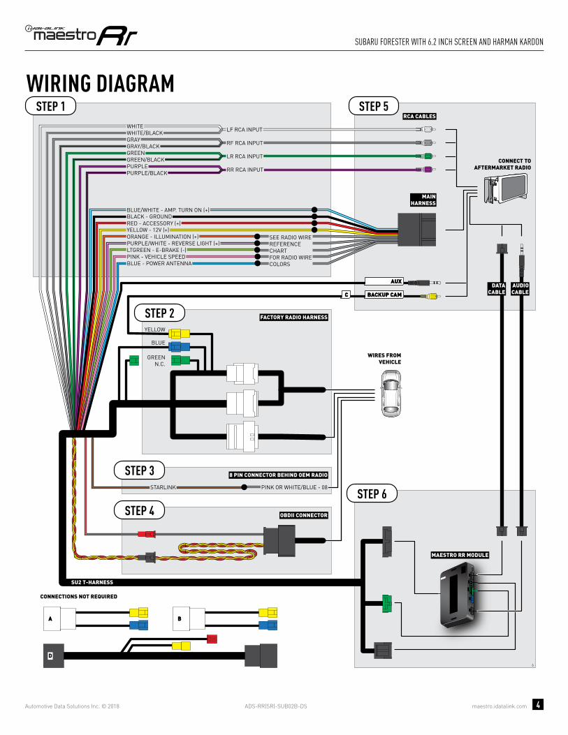
INSTALLATION INSTRUCTIONS STEP 1
• Unbox the aftermarket radio and locate its main harness.
• Connect the wires from aftermarket radio main harness to the SU2 T-harness and match the wire functions.
• Remove the factory radio.
STEP 2
• Assemble the SU2 T-harness and connect it to the factory radio harness.
STEP 3Note: Connection required if the vehicle is equipped with Starlink telematics and a SOS button.
• Connect the BROWN Starlink wire to PINK or WHITE/BLUE (pin 8) of the 8 pin connector behind the OEM Radio.
STEP 4• Plug the OBDII connector into the OBDII of the vehicle,
under driver dash.
STEP 5• Plug the aftermarket radio harnesses into the aftermarket
radio.
• Plug the AUX cable to the aftermarket radio.
• Plug the RCA cable to the aftermarket radio.
• Plug the Data cable to the data port of the aftermarket radio.
• Insert the Audio cable into the iDatalink 3.5 mm audio jack of the aftermarket radio.
STEP 6• Connect all the harnesses to the Maestro RR module then
test your installation.
TROUBLESHOOTING TIPS:
• To reset the module back its factory settings, turn the key to the OFF position then disconnect all connectors from the module. Press and hold the module’s programming button and connect all the connectors back to the module. Wait, the module’s LED will fl ash RED rapidly (this may take up to 10 seconds). Release the programming button. Wait, the LED will turn solid GREEN for 2 seconds.
• For technical assistance call 1-866-427-2999 or e-mail “[email protected]”. Visit us at “maestro.idatalink.com/support” and “www.12voltdata.com/forum/”
6
ADS-RR(SR)-SUB02B-DS maestro.idatalink.com
suBaRu foResteR with 6.2 inch scReen and haRman KaRdon
Automotive Data Solutions Inc. © 2018 4
6
BACKUP CAMBACKUP CAMCC
AUXAUX
AA
D
BB
STARLINK PINK OR WHITE/BLUE - 08
8 PIN CONNECTOR BEHIND OEM RADIOSTEP 3
MAESTRO RR MODULE
STEP 1
SU2 T-HARNESS
STEP 5
STEP 6
WIRING DIAGRAM
WIRES FROMVEHICLE
FACTORY RADIO HARNESSSTEP 2
STEP 4 OBDII CONNECTOR
DATACABLE
AUDIOCABLE
CONNECT TOAFTERMARKET RADIO
BLUE
CONNECTIONS NOT REQUIRED
YELLOW
MAINHARNESS
YELLOW - 12V (+)
BLACK - GROUNDRED - ACCESSORY (+)
BLUE/WHITE - AMP. TURN ON (+)
ORANGE - ILLUMINATION (+)PURPLE/WHITE - REVERSE LIGHT (+)LTGREEN - E-BRAKE (-)
BLUE - POWER ANTENNAPINK - VEHICLE SPEED
SEE RADIO WIREREFERENCECHARTFOR RADIO WIRECOLORS
WHITEWHITE/BLACKGRAYGRAY/BLACKGREENGREEN/BLACK
PURPLE/BLACKPURPLE
LF RCA INPUT
RF RCA INPUT
LR RCA INPUT
RR RCA INPUT
RCA CABLES
GREENN.C.

ADS-RR(SR)-SUB02B-DS maestro.idatalink.com
suBaRu foResteR with 6.2 inch scReen and haRman KaRdon
Automotive Data Solutions Inc. © 2018 5
RADIO WIRE REFERENCE CHART
WireDescription Polarity Wire Color on Maestro
T-Harness Wire Color on Alpine cable Wire Color on Kenwood cable Wire Color on Pioneer cable
Illumination (+) Orange N/A Orange/White Orange/White
Reverse Light (+) Purple/White Orange/White Purple/White Purple/White
E-Brake (-) Lt Green Yellow/Blue Lt Green Lt Green
VSS (vehicle speed sensor) (DATA) Pink Green/White N/A Pink
Power Antenna (+) Blue Blue Blue N/A

PROGRAMMED FIRMWAREADS-RR(SR)-SUB02B-DS
PRODUCTS REQUIREDiDatalink Maestro RR Radio Replacement InterfaceiDatalink Maestro SU2 Installation Harness
OPTIONAL ACCESSORIES
ACC-uSU2
Click here for: Radar Integration Installation GuideRadar Integration Owner’s Guide for Kenwood and JVC Radios
E L E C T R O N I C S
INSTALL GUIDESUBARU FORESTER
WITh 7 INCh SCREEN
2016-2018Retains steeRing wheel contRols, amplifieR and moRe!
NOTICE: Automotive Data Solutions Inc. (ADS) recommends having this installation performed by a certified technician. Logos and trademarks used here in are the properties of their respective owners.

ADS-RR(SR)-SUB02B-DS maestro.idatalink.com
suBaRu foResteR with 7 inch scReen 2016-2018
Automotive Data Solutions Inc. © 2018 2
WELCOME
NEED hELP?
Congratulations on the purchase of your iDatalink Maestro RR Radio replacement solution. You are now a few simple steps away from enjoying your new car radio with enhanced features. Before starting your installation, please ensure that your iDatalink Maestro module is programmed with the correct fi rmware and that you carefully review the Installation Diagram and Vehicle Wire Refer-ence Chart.
Please note that Maestro RR will only retain functionalities that were originally available in the vehicle.
1 866 427-2999
maestro.idatalink.com/supportwww.12voltdata.com/forum
TABLE OF CONTENTS
Installation Instructions 3
Wiring Diagram 4
Radio Wire Reference Chart 5

ADS-RR(SR)-SUB02B-DS maestro.idatalink.com
suBaRu foResteR with 7 inch scReen 2016-2018
Automotive Data Solutions Inc. © 2018 3
INSTALLATION INSTRUCTIONS STEP 1
• Unbox the aftermarket radio and locate its main harness.
• Cut the WHITE, GRAY, GREEN and PURPLE RCA tips.
• Connect the wires from aftermarket radio main harness to the SU2 T-harness and match the wire functions.
• Remove the factory radio.
STEP 2
• Assemble the SU2 T-harness and connect it to the factory radio harness.
STEP 3Note: Connection required if the vehicle is equipped with Starlink telematics and a SOS button.
• Connect the BROWN Starlink wire to PINK or WHITE/BLUE (pin 8) of the 8 pin connector behind the OEM Radio.
STEP 4• Plug the OBDII connector into the OBDII of the vehicle,
under driver dash.
STEP 5• Plug the aftermarket radio harnesses into the aftermarket
radio.
• Plug the AUX cable to the aftermarket radio.
• Plug the RCA cable to the aftermarket radio.
• Plug the Data cable to the data port of the aftermarket radio.
• Insert the Audio cable into the iDatalink 3.5 mm audio jack of the aftermarket radio.
STEP 6• Connect all the harnesses to the Maestro RR module then
test your installation.
TROUBLESHOOTING TIPS:
• To reset the module back its factory settings, turn the key to the OFF position then disconnect all connectors from the module. Press and hold the module’s programming button and connect all the connectors back to the module. Wait, the module’s LED will fl ash RED rapidly (this may take up to 10 seconds). Release the programming button. Wait, the LED will turn solid GREEN for 2 seconds.
• For technical assistance call 1-866-427-2999 or e-mail “[email protected]”. Visit us at “maestro.idatalink.com/support” and “www.12voltdata.com/forum/”
5

ADS-RR(SR)-SUB02B-DS maestro.idatalink.com
suBaRu foResteR with 7 inch scReen 2016-2018
Automotive Data Solutions Inc. © 2018 4
5
BACKUP CAMBACKUP CAMCC
AA
AUXAUX
BB
D
GREENN.C.
MAESTRO RR MODULE
CUT AND REMOVE THE RCA JACKS
STEP 1
MAINHARNESS
SU2 T-HARNESS
WHITE - LF SPEAKER (+)WHITE/BLACK - LF SPEAKER (-)GRAY - RF SPEAKER (+)GRAY/BLACK - RF SPEAKER (-)GREEN - LR SPEAKER (+)GREEN/BLACK - LR SPEAKER (-)
PURPLE/BLACK - RR SPEAKER (-)
YELLOW - 12V (+)
BLACK - GROUNDRED - ACCESSORY (+)
BLUE/WHITE - AMP. TURN ON (+)
PURPLE - RR SPEAKER (+)
STEP 5
STEP 6
ORANGE - ILLUMINATION (+)PURPLE/WHITE - REVERSE LIGHT (+)LTGREEN - E-BRAKE (-)
BLUE - POWER ANTENNA
STARLINK PINK OR WHITE/BLUE - 08
PINK - VEHICLE SPEED
WIRING DIAGRAM
WIRES FROMVEHICLE
FACTORY RADIO HARNESS
8 PIN CONNECTOR BEHIND OEM RADIO
STEP 2
STEP 4
STEP 3
OBDII CONNECTOR
SEE RADIO WIREREFERENCECHARTFOR RADIO WIRECOLORS
DATACABLE
AUDIOCABLE
CONNECT TOAFTERMARKET RADIO
CONNECTIONS NOT REQUIRED
BLUE
NC
NC
YELLOW

ADS-RR(SR)-SUB02B-DS maestro.idatalink.com
suBaRu foResteR with 7 inch scReen 2016-2018
Automotive Data Solutions Inc. © 2018 5
RADIO WIRE REFERENCE CHART
WireDescription Polarity Wire Color on Maestro
T-Harness Wire Color on Alpine cable Wire Color on Kenwood cable Wire Color on Pioneer cable
Illumination (+) Orange N/A Orange/White Orange/White
Reverse Light (+) Purple/White Orange/White Purple/White Purple/White
E-Brake (-) Lt Green Yellow/Blue Lt Green Lt Green
VSS (vehicle speed sensor) (DATA) Pink Green/White N/A Pink
Power Antenna (+) Blue Blue Blue N/A

PROGRAMMED FIRMWAREADS-RR(SR)-SUB02B-DS
PRODUCTS REQUIREDiDatalink Maestro RR Radio Replacement InterfaceiDatalink Maestro SU2 Installation Harness
OPTIONAL ACCESSORIES
ACC-uSU2
Click here for: Radar Integration Installation GuideRadar Integration Owner’s Guide for Kenwood and JVC Radios
E L E C T R O N I C S
INSTALL GUIDESUBARU FORESTER
WITh 7 INCh SCREEN AND hARMAN KARDON
2016-2018Retains steeRing wheel contRols, amplifieR and moRe!
NOTICE: Automotive Data Solutions Inc. (ADS) recommends having this installation performed by a certified technician. Logos and trademarks used here in are the properties of their respective owners.

ADS-RR(SR)-SUB02B-DS maestro.idatalink.com
suBaRu foResteR with 7 inch scReen and haRman KaRdon
Automotive Data Solutions Inc. © 2018 2
WELCOME
NEED hELP?
Congratulations on the purchase of your iDatalink Maestro RR Radio replacement solution. You are now a few simple steps away from enjoying your new car radio with enhanced features. Before starting your installation, please ensure that your iDatalink Maestro module is programmed with the correct fi rmware and that you carefully review the Installation Diagram and Vehicle Wire Refer-ence Chart.
Please note that Maestro RR will only retain functionalities that were originally available in the vehicle.
1 866 427-2999
maestro.idatalink.com/supportwww.12voltdata.com/forum
TABLE OF CONTENTS
Installation Instructions 3
Wiring Diagram 4
Radio Wire Reference Chart 5

ADS-RR(SR)-SUB02B-DS maestro.idatalink.com
suBaRu foResteR with 7 inch scReen and haRman KaRdon
Automotive Data Solutions Inc. © 2018 3
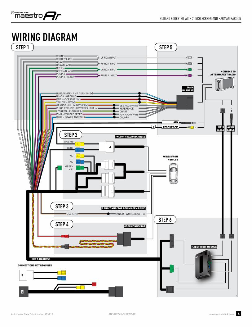
INSTALLATION INSTRUCTIONS STEP 1
• Unbox the aftermarket radio and locate its main harness.
• Connect the wires from aftermarket radio main harness to the SU2 T-harness and match the wire functions.
• Remove the factory radio.
STEP 2
• Assemble the SU2 T-harness and connect it to the factory radio harness.
STEP 3Note: Connection required if the vehicle is equipped with Starlink telematics and a SOS button.
• Connect the BROWN Starlink wire to PINK or WHITE/BLUE (pin 8) of the 8 pin connector behind the OEM Radio.
STEP 4• Plug the OBDII connector into the OBDII of the vehicle,
under driver dash.
STEP 5• Plug the aftermarket radio harnesses into the aftermarket
radio.
• Plug the AUX cable to the aftermarket radio.
• Plug the RCA cable to the aftermarket radio.
• Plug the Data cable to the data port of the aftermarket radio.
• Insert the Audio cable into the iDatalink 3.5 mm audio jack of the aftermarket radio.
STEP 6• Connect all the harnesses to the Maestro RR module then
test your installation.
TROUBLESHOOTING TIPS:
• To reset the module back its factory settings, turn the key to the OFF position then disconnect all connectors from the module. Press and hold the module’s programming button and connect all the connectors back to the module. Wait, the module’s LED will fl ash RED rapidly (this may take up to 10 seconds). Release the programming button. Wait, the LED will turn solid GREEN for 2 seconds.
• For technical assistance call 1-866-427-2999 or e-mail “[email protected]”. Visit us at “maestro.idatalink.com/support” and “www.12voltdata.com/forum/”
7
ADS-RR(SR)-SUB02B-DS maestro.idatalink.com
suBaRu foResteR with 7 inch scReen and haRman KaRdon
Automotive Data Solutions Inc. © 2018 4
7
BACKUP CAMBACKUP CAMCC
AA
AUXAUX
BB
D
GREENN.C.
MAESTRO RR MODULE
STEP 1
SU2 T-HARNESS
STEP 5
STEP 6STARLINK PINK OR WHITE/BLUE - 08
WIRING DIAGRAM
WIRES FROMVEHICLE
FACTORY RADIO HARNESS
8 PIN CONNECTOR BEHIND OEM RADIO
STEP 2
STEP 4
STEP 3
OBDII CONNECTOR
DATACABLE
AUDIOCABLE
CONNECT TOAFTERMARKET RADIO
CONNECTIONS NOT REQUIRED
BLUE
NC
NC
YELLOW
MAINHARNESS
YELLOW - 12V (+)
BLACK - GROUNDRED - ACCESSORY (+)
BLUE/WHITE - AMP. TURN ON (+)
ORANGE - ILLUMINATION (+)PURPLE/WHITE - REVERSE LIGHT (+)LTGREEN - E-BRAKE (-)
BLUE - POWER ANTENNAPINK - VEHICLE SPEED
SEE RADIO WIREREFERENCECHARTFOR RADIO WIRECOLORS
WHITEWHITE/BLACKGRAYGRAY/BLACKGREENGREEN/BLACK
PURPLE/BLACKPURPLE
LF RCA INPUT
RF RCA INPUT
LR RCA INPUT
RR RCA INPUT

ADS-RR(SR)-SUB02B-DS maestro.idatalink.com
suBaRu foResteR with 7 inch scReen and haRman KaRdon
Automotive Data Solutions Inc. © 2018 5
RADIO WIRE REFERENCE CHART
WireDescription Polarity Wire Color on Maestro
T-Harness Wire Color on Alpine cable Wire Color on Kenwood cable Wire Color on Pioneer cable
Illumination (+) Orange N/A Orange/White Orange/White
Reverse Light (+) Purple/White Orange/White Purple/White Purple/White
E-Brake (-) Lt Green Yellow/Blue Lt Green Lt Green
VSS (vehicle speed sensor) (DATA) Pink Green/White N/A Pink
Power Antenna (+) Blue Blue Blue N/A

PROGRAMMED FIRMWAREADS-RR(SR)-SUB02B-DS
PRODUCTS REQUIREDiDatalink Maestro RR Radio Replacement InterfaceiDatalink Maestro SU2 Installation Harness
OPTIONAL ACCESSORIES
ACC-uSU2
Click here for: Radar Integration Installation GuideRadar Integration Owner’s Guide for Kenwood and JVC Radios
E L E C T R O N I C S
INSTALL GUIDESUBARU FORESTER
WITh NAV
2014-2015Retains steeRing wheel contRols, amplifieR and moRe!
NOTICE: Automotive Data Solutions Inc. (ADS) recommends having this installation performed by a certified technician. Logos and trademarks used here in are the properties of their respective owners.

ADS-RR(SR)-SUB02B-DS maestro.idatalink.com
suBaRu foResteR with naV 2014-2015
Automotive Data Solutions Inc. © 2018 2
WELCOME
NEED hELP?
Congratulations on the purchase of your iDatalink Maestro RR Radio replacement solution. You are now a few simple steps away from enjoying your new car radio with enhanced features. Before starting your installation, please ensure that your iDatalink Maestro module is programmed with the correct fi rmware and that you carefully review the Installation Diagram and Vehicle Wire Refer-ence Chart.
Please note that Maestro RR will only retain functionalities that were originally available in the vehicle.
1 866 427-2999
maestro.idatalink.com/supportwww.12voltdata.com/forum
TABLE OF CONTENTS
Installation Instructions 3
Wiring Diagram 4
Radio Wire Reference Chart 5

ADS-RR(SR)-SUB02B-DS maestro.idatalink.com
suBaRu foResteR with naV 2014-2015
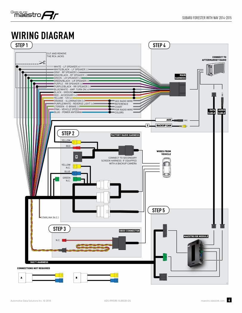
Automotive Data Solutions Inc. © 2018 3
INSTALLATION INSTRUCTIONS STEP 1
• Unbox the aftermarket radio and locate its main harness.
• Cut the WHITE, GRAY, GREEN and PURPLE RCA tips.
• Connect the wires from aftermarket radio main harness to the SU2 T-harness and match the wire functions.
• Remove the factory radio.
STEP 2
• Assemble the SU2 T-harness and connect it to the factory radio harness.
STEP 3• Plug the OBDII connector into the OBDII of the vehicle,
under driver dash.
STEP 4• Plug the aftermarket radio harnesses into the aftermarket
radio.
• Plug the AUX cable to the aftermarket radio.
• Plug the RCA cable to the aftermarket radio.
• Plug the Data cable to the data port of the aftermarket radio.
• Insert the Audio cable into the iDatalink 3.5 mm audio jack of the aftermarket radio.
STEP 5• Connect all the harnesses to the Maestro RR module then
test your installation.
TROUBLESHOOTING TIPS:
• To reset the module back its factory settings, turn the key to the OFF position then disconnect all connectors from the module. Press and hold the module’s programming button and connect all the connectors back to the module. Wait, the module’s LED will fl ash RED rapidly (this may take up to 10 seconds). Release the programming button. Wait, the LED will turn solid GREEN for 2 seconds.
• For technical assistance call 1-866-427-2999 or e-mail “[email protected]”. Visit us at “maestro.idatalink.com/support” and “www.12voltdata.com/forum/”
2
ADS-RR(SR)-SUB02B-DS maestro.idatalink.com
suBaRu foResteR with naV 2014-2015
Automotive Data Solutions Inc. © 2018 4
2
D
BACKUP CAMBACKUP CAMCC
AUXAUX
AA BB
MAESTRO RR MODULE
CUT AND REMOVE THE RCA JACKS
STEP 1
MAINHARNESS
SU2 T-HARNESS
WHITE - LF SPEAKER (+)WHITE/BLACK - LF SPEAKER (-)GRAY - RF SPEAKER (+)GRAY/BLACK - RF SPEAKER (-)GREEN - LR SPEAKER (+)GREEN/BLACK - LR SPEAKER (-)
PURPLE/BLACK - RR SPEAKER (-)
YELLOW - 12V (+)
BLACK - GROUNDRED - ACCESSORY (+)
BLUE/WHITE - AMP. TURN ON (+)
PURPLE - RR SPEAKER (+)
STEP 4
STEP 5
ORANGE - ILLUMINATION (+)PURPLE/WHITE - REVERSE LIGHT (+)LTGREEN - E-BRAKE (-)
BLUE - POWER ANTENNAPINK - VEHICLE SPEED
WIRING DIAGRAM
WIRES FROMVEHICLE
FACTORY RADIO HARNESSSTEP 2
STEP 3 OBDII CONNECTOR
SEE RADIO WIREREFERENCECHARTFOR RADIO WIRECOLORS
CONNECT TO SECONDARYSCREEN HARNESS IF EQUIPPED
WITH A BACKUP CAMERA
DATACABLE
AUDIOCABLE
CONNECT TOAFTERMARKET RADIO
BLUE
GREENN.C.
N.C.
CONNECTIONS NOT REQUIRED
YELLOWN.C.
YELLOW
RED
STARLINK (N.C.)

ADS-RR(SR)-SUB02B-DS maestro.idatalink.com
suBaRu foResteR with naV 2014-2015
Automotive Data Solutions Inc. © 2018 5
RADIO WIRE REFERENCE CHART
WireDescription Polarity Wire Color on Maestro
T-Harness Wire Color on Alpine cable Wire Color on Kenwood cable Wire Color on Pioneer cable
Illumination (+) Orange N/A Orange/White Orange/White
Reverse Light (+) Purple/White Orange/White Purple/White Purple/White
E-Brake (-) Lt Green Yellow/Blue Lt Green Lt Green
VSS (vehicle speed sensor) (DATA) Pink Green/White N/A Pink
Power Antenna (+) Blue Blue Blue N/A

PROGRAMMED FIRMWAREADS-RR(SR)-SUB02B-DS
PRODUCTS REQUIREDiDatalink Maestro RR Radio Replacement InterfaceiDatalink Maestro SU2 Installation Harness
OPTIONAL ACCESSORIES
ACC-uSU2
Click here for: Radar Integration Installation GuideRadar Integration Owner’s Guide for Kenwood and JVC Radios
E L E C T R O N I C S
INSTALL GUIDESUBARU FORESTER
WITh NAV AND hARMAN KARDON
2014-2015Retains steeRing wheel contRols, amplifieR and moRe!
NOTICE: Automotive Data Solutions Inc. (ADS) recommends having this installation performed by a certified technician. Logos and trademarks used here in are the properties of their respective owners.

ADS-RR(SR)-SUB02B-DS maestro.idatalink.com
suBaRu foResteR with naV and haRman KaRdon 2014-2015
Automotive Data Solutions Inc. © 2018 2
WELCOME
NEED hELP?
Congratulations on the purchase of your iDatalink Maestro RR Radio replacement solution. You are now a few simple steps away from enjoying your new car radio with enhanced features. Before starting your installation, please ensure that your iDatalink Maestro module is programmed with the correct fi rmware and that you carefully review the Installation Diagram and Vehicle Wire Refer-ence Chart.
Please note that Maestro RR will only retain functionalities that were originally available in the vehicle.
1 866 427-2999
maestro.idatalink.com/supportwww.12voltdata.com/forum
TABLE OF CONTENTS
Installation Instructions 3
Wiring Diagram 4
Radio Wire Reference Chart 5

ADS-RR(SR)-SUB02B-DS maestro.idatalink.com
suBaRu foResteR with naV and haRman KaRdon 2014-2015
Automotive Data Solutions Inc. © 2018 3
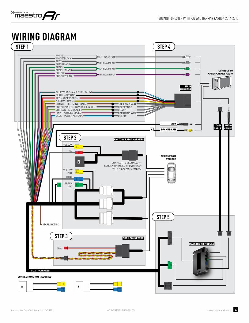
INSTALLATION INSTRUCTIONS STEP 1
• Unbox the aftermarket radio and locate its main harness.
• Connect the wires from aftermarket radio main harness to the SU2 T-harness and match the wire functions.
• Remove the factory radio.
STEP 2
• Assemble the SU2 T-harness and connect it to the factory radio harness.
STEP 3• Plug the OBDII connector into the OBDII of the vehicle,
under driver dash.
STEP 4• Plug the aftermarket radio harnesses into the aftermarket
radio.
• Plug the AUX cable to the aftermarket radio.
• Plug the RCA cable to the aftermarket radio.
• Plug the Data cable to the data port of the aftermarket radio.
• Insert the Audio cable into the iDatalink 3.5 mm audio jack of the aftermarket radio.
STEP 5• Connect all the harnesses to the Maestro RR module then
test your installation.
TROUBLESHOOTING TIPS:
• To reset the module back its factory settings, turn the key to the OFF position then disconnect all connectors from the module. Press and hold the module’s programming button and connect all the connectors back to the module. Wait, the module’s LED will fl ash RED rapidly (this may take up to 10 seconds). Release the programming button. Wait, the LED will turn solid GREEN for 2 seconds.
• For technical assistance call 1-866-427-2999 or e-mail “[email protected]”. Visit us at “maestro.idatalink.com/support” and “www.12voltdata.com/forum/”
3
ADS-RR(SR)-SUB02B-DS maestro.idatalink.com
suBaRu foResteR with naV and haRman KaRdon 2014-2015
Automotive Data Solutions Inc. © 2018 4
3
D
BACKUP CAMBACKUP CAMCC
AUXAUX
AA BB
MAESTRO RR MODULE
STEP 1
SU2 T-HARNESS
STEP 4
STEP 5
WIRING DIAGRAM
WIRES FROMVEHICLE
FACTORY RADIO HARNESSSTEP 2
STEP 3 OBDII CONNECTOR
CONNECT TO SECONDARYSCREEN HARNESS IF EQUIPPED
WITH A BACKUP CAMERA
DATACABLE
AUDIOCABLE
CONNECT TOAFTERMARKET RADIO
BLUE
GREENN.C.
N.C.
CONNECTIONS NOT REQUIRED
YELLOWN.C.
YELLOW
RED
MAINHARNESS
YELLOW - 12V (+)
BLACK - GROUNDRED - ACCESSORY (+)
BLUE/WHITE - AMP. TURN ON (+)
ORANGE - ILLUMINATION (+)PURPLE/WHITE - REVERSE LIGHT (+)LTGREEN - E-BRAKE (-)
BLUE - POWER ANTENNAPINK - VEHICLE SPEED
SEE RADIO WIREREFERENCECHARTFOR RADIO WIRECOLORS
WHITEWHITE/BLACKGRAYGRAY/BLACKGREENGREEN/BLACK
PURPLE/BLACKPURPLE
LF RCA INPUT
RF RCA INPUT
LR RCA INPUT
RR RCA INPUT
STARLINK (N.C.)

ADS-RR(SR)-SUB02B-DS maestro.idatalink.com
suBaRu foResteR with naV and haRman KaRdon 2014-2015
Automotive Data Solutions Inc. © 2018 5
RADIO WIRE REFERENCE CHART
WireDescription Polarity Wire Color on Maestro
T-Harness Wire Color on Alpine cable Wire Color on Kenwood cable Wire Color on Pioneer cable
Illumination (+) Orange N/A Orange/White Orange/White
Reverse Light (+) Purple/White Orange/White Purple/White Purple/White
E-Brake (-) Lt Green Yellow/Blue Lt Green Lt Green
VSS (vehicle speed sensor) (DATA) Pink Green/White N/A Pink
Power Antenna (+) Blue Blue Blue N/A

PROGRAMMED FIRMWAREADS-RR(SR)-SUB02B-DS
PRODUCTS REQUIREDiDatalink Maestro RR Radio Replacement InterfaceiDatalink Maestro SU2 Installation Harness
OPTIONAL ACCESSORIES
ACC-uSU2
Click here for: Radar Integration Installation GuideRadar Integration Owner’s Guide for Kenwood and JVC Radios
E L E C T R O N I C S
INSTALL GUIDESUBARU FORESTER
WITh NAV AND SD CARD
2012Retains steeRing wheel contRols, amplifieR and moRe!
NOTICE: Automotive Data Solutions Inc. (ADS) recommends having this installation performed by a certified technician. Logos and trademarks used here in are the properties of their respective owners.

ADS-RR(SR)-SUB02B-DS maestro.idatalink.com
suBaRu foResteR with naV and sd caRd 2012
Automotive Data Solutions Inc. © 2018 2
WELCOME
NEED hELP?
Congratulations on the purchase of your iDatalink Maestro RR Radio replacement solution. You are now a few simple steps away from enjoying your new car radio with enhanced features. Before starting your installation, please ensure that your iDatalink Maestro module is programmed with the correct fi rmware and that you carefully review the Installation Diagram and Vehicle Wire Refer-ence Chart.
Please note that Maestro RR will only retain functionalities that were originally available in the vehicle.
1 866 427-2999
maestro.idatalink.com/supportwww.12voltdata.com/forum
TABLE OF CONTENTS
Installation Instructions 3
Wiring Diagram 4
Radio Wire Reference Chart 5

ADS-RR(SR)-SUB02B-DS maestro.idatalink.com
suBaRu foResteR with naV and sd caRd 2012
Automotive Data Solutions Inc. © 2018 3
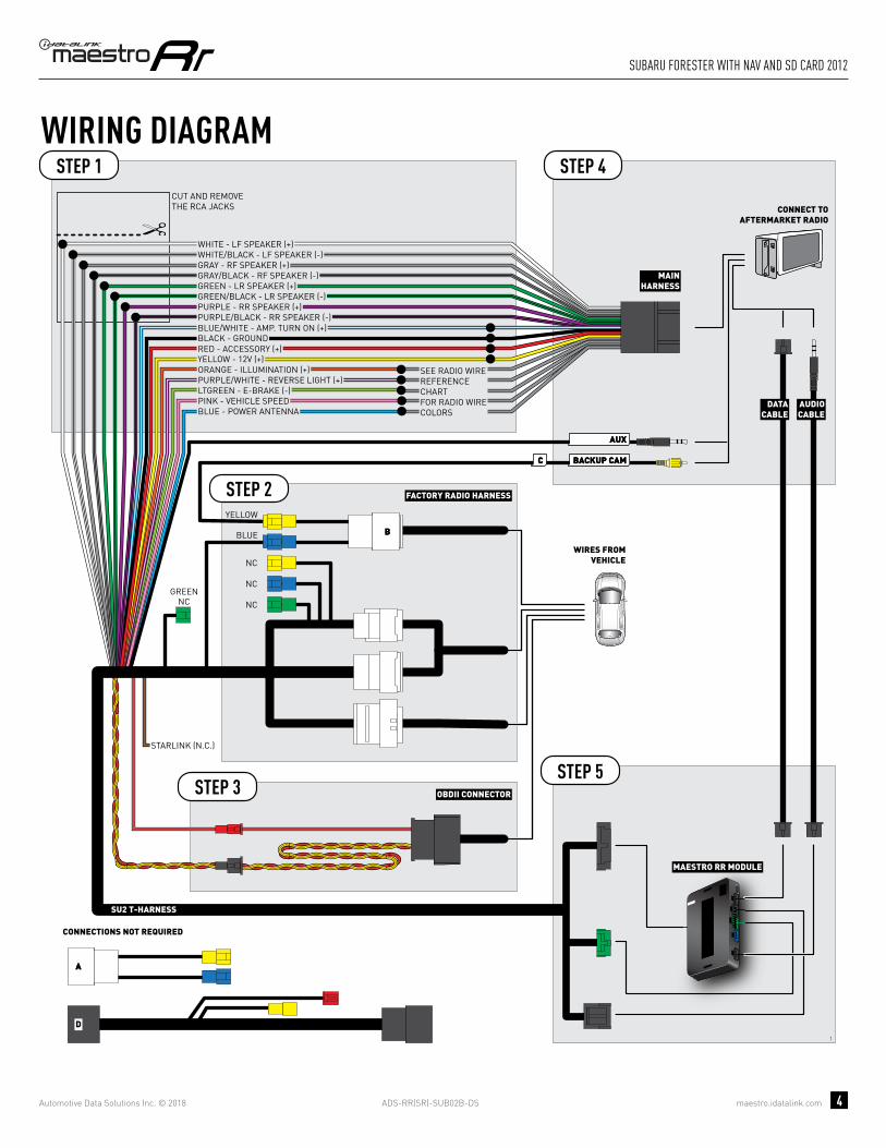
INSTALLATION INSTRUCTIONS STEP 1
• Unbox the aftermarket radio and locate its main harness.
• Cut the WHITE, GRAY, GREEN and PURPLE RCA tips.
• Connect the wires from aftermarket radio main harness to the SU2 T-harness and match the wire functions.
• Remove the factory radio.
STEP 2
• Assemble the SU2 T-harness and connect it to the factory radio harness.
STEP 3• Plug the OBDII connector into the OBDII of the vehicle,
under driver dash.
STEP 4• Plug the aftermarket radio harnesses into the aftermarket
radio.
• Plug the AUX cable to the aftermarket radio.
• Plug the RCA cable to the aftermarket radio.
• Plug the Data cable to the data port of the aftermarket radio.
• Insert the Audio cable into the iDatalink 3.5 mm audio jack of the aftermarket radio.
STEP 5• Connect all the harnesses to the Maestro RR module then
test your installation.
TROUBLESHOOTING TIPS:
• To reset the module back its factory settings, turn the key to the OFF position then disconnect all connectors from the module. Press and hold the module’s programming button and connect all the connectors back to the module. Wait, the module’s LED will fl ash RED rapidly (this may take up to 10 seconds). Release the programming button. Wait, the LED will turn solid GREEN for 2 seconds.
• For technical assistance call 1-866-427-2999 or e-mail “[email protected]”. Visit us at “maestro.idatalink.com/support” and “www.12voltdata.com/forum/”
1
ADS-RR(SR)-SUB02B-DS maestro.idatalink.com
suBaRu foResteR with naV and sd caRd 2012
Automotive Data Solutions Inc. © 2018 4
1
BACKUP CAMBACKUP CAMCC
AUXAUX
AA
D
BB
MAESTRO RR MODULE
CUT AND REMOVE THE RCA JACKS
STEP 1
MAINHARNESS
SU2 T-HARNESS
WHITE - LF SPEAKER (+)WHITE/BLACK - LF SPEAKER (-)GRAY - RF SPEAKER (+)GRAY/BLACK - RF SPEAKER (-)GREEN - LR SPEAKER (+)GREEN/BLACK - LR SPEAKER (-)
PURPLE/BLACK - RR SPEAKER (-)
YELLOW - 12V (+)
BLACK - GROUNDRED - ACCESSORY (+)
BLUE/WHITE - AMP. TURN ON (+)
PURPLE - RR SPEAKER (+)
STEP 4
STEP 5
ORANGE - ILLUMINATION (+)PURPLE/WHITE - REVERSE LIGHT (+)LTGREEN - E-BRAKE (-)
BLUE - POWER ANTENNAPINK - VEHICLE SPEED
WIRING DIAGRAM
WIRES FROMVEHICLE
FACTORY RADIO HARNESSSTEP 2
STEP 3 OBDII CONNECTOR
SEE RADIO WIREREFERENCECHARTFOR RADIO WIRECOLORS
DATACABLE
AUDIOCABLE
CONNECT TOAFTERMARKET RADIO
BLUE
GREENNC
NC
NC
NC
CONNECTIONS NOT REQUIRED
YELLOW
STARLINK (N.C.)

ADS-RR(SR)-SUB02B-DS maestro.idatalink.com
suBaRu foResteR with naV and sd caRd 2012
Automotive Data Solutions Inc. © 2018 5
RADIO WIRE REFERENCE CHART
WireDescription Polarity Wire Color on Maestro
T-Harness Wire Color on Alpine cable Wire Color on Kenwood cable Wire Color on Pioneer cable
Illumination (+) Orange N/A Orange/White Orange/White
Reverse Light (+) Purple/White Orange/White Purple/White Purple/White
E-Brake (-) Lt Green Yellow/Blue Lt Green Lt Green
VSS (vehicle speed sensor) (DATA) Pink Green/White N/A Pink
Power Antenna (+) Blue Blue Blue N/A

PROGRAMMED FIRMWAREADS-RR(SR)-SUB02B-DS
PRODUCTS REQUIREDiDatalink Maestro RR Radio Replacement InterfaceiDatalink Maestro SU2 Installation Harness
OPTIONAL ACCESSORIES
ACC-uSU2
Click here for: Radar Integration Installation GuideRadar Integration Owner’s Guide for Kenwood and JVC Radios
E L E C T R O N I C S
INSTALL GUIDESUBARU FORESTER
WITh NAV AND USB
2013Retains steeRing wheel contRols, amplifieR and moRe!
NOTICE: Automotive Data Solutions Inc. (ADS) recommends having this installation performed by a certified technician. Logos and trademarks used here in are the properties of their respective owners.

ADS-RR(SR)-SUB02B-DS maestro.idatalink.com
suBaRu foResteR with naV and usB 2013
Automotive Data Solutions Inc. © 2018 2
WELCOME
NEED hELP?
Congratulations on the purchase of your iDatalink Maestro RR Radio replacement solution. You are now a few simple steps away from enjoying your new car radio with enhanced features. Before starting your installation, please ensure that your iDatalink Maestro module is programmed with the correct fi rmware and that you carefully review the Installation Diagram and Vehicle Wire Refer-ence Chart.
Please note that Maestro RR will only retain functionalities that were originally available in the vehicle.
1 866 427-2999
maestro.idatalink.com/supportwww.12voltdata.com/forum
TABLE OF CONTENTS
Installation Instructions 3
Wiring Diagram 4
Radio Wire Reference Chart 5

ADS-RR(SR)-SUB02B-DS maestro.idatalink.com
suBaRu foResteR with naV and usB 2013
Automotive Data Solutions Inc. © 2018 3
INSTALLATION INSTRUCTIONS STEP 1
• Unbox the aftermarket radio and locate its main harness.
• Cut the WHITE, GRAY, GREEN and PURPLE RCA tips.
• Connect the wires from aftermarket radio main harness to the SU2 T-harness and match the wire functions.
• Remove the factory radio.
STEP 2
• Assemble the SU2 T-harness and connect it to the factory radio harness.
STEP 3• Plug the OBDII connector into the OBDII of the vehicle,
under driver dash.
STEP 4• Plug the aftermarket radio harnesses into the aftermarket
radio.
• Plug the AUX cable to the aftermarket radio.
• Plug the RCA cable to the aftermarket radio.
• Plug the Data cable to the data port of the aftermarket radio.
• Insert the Audio cable into the iDatalink 3.5 mm audio jack of the aftermarket radio.
STEP 5• Connect all the harnesses to the Maestro RR module then
test your installation.
TROUBLESHOOTING TIPS:
• To reset the module back its factory settings, turn the key to the OFF position then disconnect all connectors from the module. Press and hold the module’s programming button and connect all the connectors back to the module. Wait, the module’s LED will fl ash RED rapidly (this may take up to 10 seconds). Release the programming button. Wait, the LED will turn solid GREEN for 2 seconds.
• For technical assistance call 1-866-427-2999 or e-mail “[email protected]”. Visit us at “maestro.idatalink.com/support” and “www.12voltdata.com/forum/”
1

ADS-RR(SR)-SUB02B-DS maestro.idatalink.com
suBaRu foResteR with naV and usB 2013
Automotive Data Solutions Inc. © 2018 4
1
BACKUP CAMBACKUP CAMCC
AUXAUX
AA
D
BB
MAESTRO RR MODULE
CUT AND REMOVE THE RCA JACKS
STEP 1
MAINHARNESS
SU2 T-HARNESS
WHITE - LF SPEAKER (+)WHITE/BLACK - LF SPEAKER (-)GRAY - RF SPEAKER (+)GRAY/BLACK - RF SPEAKER (-)GREEN - LR SPEAKER (+)GREEN/BLACK - LR SPEAKER (-)
PURPLE/BLACK - RR SPEAKER (-)
YELLOW - 12V (+)
BLACK - GROUNDRED - ACCESSORY (+)
BLUE/WHITE - AMP. TURN ON (+)
PURPLE - RR SPEAKER (+)
STEP 4
STEP 5
ORANGE - ILLUMINATION (+)PURPLE/WHITE - REVERSE LIGHT (+)LTGREEN - E-BRAKE (-)
BLUE - POWER ANTENNAPINK - VEHICLE SPEED
WIRING DIAGRAM
WIRES FROMVEHICLE
FACTORY RADIO HARNESSSTEP 2
STEP 3 OBDII CONNECTOR
SEE RADIO WIREREFERENCECHARTFOR RADIO WIRECOLORS
DATACABLE
AUDIOCABLE
CONNECT TOAFTERMARKET RADIO
BLUE
GREENNC
NC
NC
NC
CONNECTIONS NOT REQUIRED
YELLOW
STARLINK (N.C.)

ADS-RR(SR)-SUB02B-DS maestro.idatalink.com
suBaRu foResteR with naV and usB 2013
Automotive Data Solutions Inc. © 2018 5
RADIO WIRE REFERENCE CHART
WireDescription Polarity Wire Color on Maestro
T-Harness Wire Color on Alpine cable Wire Color on Kenwood cable Wire Color on Pioneer cable
Illumination (+) Orange N/A Orange/White Orange/White
Reverse Light (+) Purple/White Orange/White Purple/White Purple/White
E-Brake (-) Lt Green Yellow/Blue Lt Green Lt Green
VSS (vehicle speed sensor) (DATA) Pink Green/White N/A Pink
Power Antenna (+) Blue Blue Blue N/A

PROGRAMMED FIRMWAREADS-RR(SR)-SUB02B-DS
PRODUCTS REQUIREDiDatalink Maestro RR Radio Replacement InterfaceiDatalink Maestro SU2 Installation Harness
OPTIONAL ACCESSORIES
ACC-uSU2
Click here for: Radar Integration Installation GuideRadar Integration Owner’s Guide for Kenwood and JVC Radios
E L E C T R O N I C S
INSTALL GUIDESUBARU IMPREZA
WITh 6.2 INCh SCREEN
2015-2016Retains steeRing wheel contRols, amplifieR and moRe!
NOTICE: Automotive Data Solutions Inc. (ADS) recommends having this installation performed by a certified technician. Logos and trademarks used here in are the properties of their respective owners.
ADS-RR(SR)-SUB02B-DS maestro.idatalink.com
suBaRu impReZa with 6.2 inch scReen 2015-2016
Automotive Data Solutions Inc. © 2018 2
WELCOME
NEED hELP?
Congratulations on the purchase of your iDatalink Maestro RR Radio replacement solution. You are now a few simple steps away from enjoying your new car radio with enhanced features. Before starting your installation, please ensure that your iDatalink Maestro module is programmed with the correct fi rmware and that you carefully review the Installation Diagram and Vehicle Wire Refer-ence Chart.
Please note that Maestro RR will only retain functionalities that were originally available in the vehicle.
1 866 427-2999
maestro.idatalink.com/supportwww.12voltdata.com/forum
TABLE OF CONTENTS
Installation Instructions 3
Wiring Diagram 4
Radio Wire Reference Chart 5
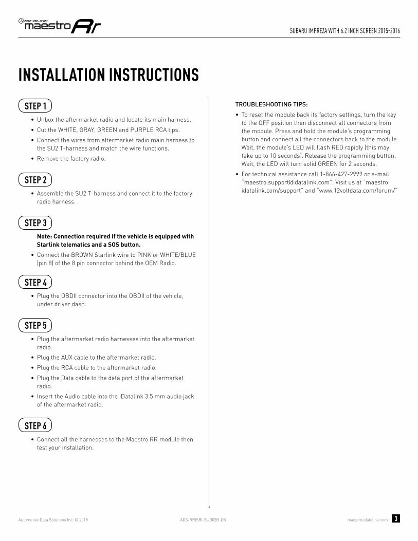
ADS-RR(SR)-SUB02B-DS maestro.idatalink.com
suBaRu impReZa with 6.2 inch scReen 2015-2016
Automotive Data Solutions Inc. © 2018 3
INSTALLATION INSTRUCTIONS STEP 1
• Unbox the aftermarket radio and locate its main harness.
• Cut the WHITE, GRAY, GREEN and PURPLE RCA tips.
• Connect the wires from aftermarket radio main harness to the SU2 T-harness and match the wire functions.
• Remove the factory radio.
STEP 2
• Assemble the SU2 T-harness and connect it to the factory radio harness.
STEP 3Note: Connection required if the vehicle is equipped with Starlink telematics and a SOS button.
• Connect the BROWN Starlink wire to PINK or WHITE/BLUE (pin 8) of the 8 pin connector behind the OEM Radio.
STEP 4• Plug the OBDII connector into the OBDII of the vehicle,
under driver dash.
STEP 5• Plug the aftermarket radio harnesses into the aftermarket
radio.
• Plug the AUX cable to the aftermarket radio.
• Plug the RCA cable to the aftermarket radio.
• Plug the Data cable to the data port of the aftermarket radio.
• Insert the Audio cable into the iDatalink 3.5 mm audio jack of the aftermarket radio.
STEP 6• Connect all the harnesses to the Maestro RR module then
test your installation.
TROUBLESHOOTING TIPS:
• To reset the module back its factory settings, turn the key to the OFF position then disconnect all connectors from the module. Press and hold the module’s programming button and connect all the connectors back to the module. Wait, the module’s LED will fl ash RED rapidly (this may take up to 10 seconds). Release the programming button. Wait, the LED will turn solid GREEN for 2 seconds.
• For technical assistance call 1-866-427-2999 or e-mail “[email protected]”. Visit us at “maestro.idatalink.com/support” and “www.12voltdata.com/forum/”
4

ADS-RR(SR)-SUB02B-DS maestro.idatalink.com
suBaRu impReZa with 6.2 inch scReen 2015-2016
Automotive Data Solutions Inc. © 2018 4
4
BACKUP CAMBACKUP CAMCC
AUXAUX
AA
D
BB
MAESTRO RR MODULE
CUT AND REMOVE THE RCA JACKS
STEP 1
MAINHARNESS
SU2 T-HARNESS
WHITE - LF SPEAKER (+)WHITE/BLACK - LF SPEAKER (-)GRAY - RF SPEAKER (+)GRAY/BLACK - RF SPEAKER (-)GREEN - LR SPEAKER (+)GREEN/BLACK - LR SPEAKER (-)
PURPLE/BLACK - RR SPEAKER (-)
YELLOW - 12V (+)
BLACK - GROUNDRED - ACCESSORY (+)
BLUE/WHITE - AMP. TURN ON (+)
PURPLE - RR SPEAKER (+)
STEP 5
STEP 6
ORANGE - ILLUMINATION (+)PURPLE/WHITE - REVERSE LIGHT (+)LTGREEN - E-BRAKE (-)
BLUE - POWER ANTENNAPINK - VEHICLE SPEED
WIRING DIAGRAM
WIRES FROMVEHICLE
FACTORY RADIO HARNESSSTEP 2
STEP 4 OBDII CONNECTOR
SEE RADIO WIREREFERENCECHARTFOR RADIO WIRECOLORS
DATACABLE
AUDIOCABLE
CONNECT TOAFTERMARKET RADIO
BLUE
GREENN.C.
CONNECTIONS NOT REQUIRED
YELLOW
STARLINK PINK OR WHITE/BLUE - 08
8 PIN CONNECTOR BEHIND OEM RADIOSTEP 3

ADS-RR(SR)-SUB02B-DS maestro.idatalink.com
suBaRu impReZa with 6.2 inch scReen 2015-2016
Automotive Data Solutions Inc. © 2018 5
RADIO WIRE REFERENCE CHART
WireDescription Polarity Wire Color on Maestro
T-Harness Wire Color on Alpine cable Wire Color on Kenwood cable Wire Color on Pioneer cable
Illumination (+) Orange N/A Orange/White Orange/White
Reverse Light (+) Purple/White Orange/White Purple/White Purple/White
E-Brake (-) Lt Green Yellow/Blue Lt Green Lt Green
VSS (vehicle speed sensor) (DATA) Pink Green/White N/A Pink
Power Antenna (+) Blue Blue Blue N/A

PROGRAMMED FIRMWAREADS-RR(SR)-SUB02B-DS
PRODUCTS REQUIREDiDatalink Maestro RR Radio Replacement InterfaceiDatalink Maestro SU2 Installation Harness
OPTIONAL ACCESSORIES
ACC-uSU2
Click here for: Radar Integration Installation GuideRadar Integration Owner’s Guide for Kenwood and JVC Radios
E L E C T R O N I C S
INSTALL GUIDESUBARU IMPREZA
WITh 6.2 INCh SCREEN AND hARMAN KARDON
2015-2016Retains steeRing wheel contRols, amplifieR and moRe!
NOTICE: Automotive Data Solutions Inc. (ADS) recommends having this installation performed by a certified technician. Logos and trademarks used here in are the properties of their respective owners.

ADS-RR(SR)-SUB02B-DS maestro.idatalink.com
suBaRu impReZa with 6.2 inch scReen and haRman KaRdon
Automotive Data Solutions Inc. © 2018 2
WELCOME
NEED hELP?
Congratulations on the purchase of your iDatalink Maestro RR Radio replacement solution. You are now a few simple steps away from enjoying your new car radio with enhanced features. Before starting your installation, please ensure that your iDatalink Maestro module is programmed with the correct fi rmware and that you carefully review the Installation Diagram and Vehicle Wire Refer-ence Chart.
Please note that Maestro RR will only retain functionalities that were originally available in the vehicle.
1 866 427-2999
maestro.idatalink.com/supportwww.12voltdata.com/forum
TABLE OF CONTENTS
Installation Instructions 3
Wiring Diagram 4
Radio Wire Reference Chart 5

ADS-RR(SR)-SUB02B-DS maestro.idatalink.com
suBaRu impReZa with 6.2 inch scReen and haRman KaRdon
Automotive Data Solutions Inc. © 2018 3
INSTALLATION INSTRUCTIONS STEP 1
• Unbox the aftermarket radio and locate its main harness.
• Connect the wires from aftermarket radio main harness to the SU2 T-harness and match the wire functions.
• Remove the factory radio.
STEP 2
• Assemble the SU2 T-harness and connect it to the factory radio harness.
STEP 3Note: Connection required if the vehicle is equipped with Starlink telematics and a SOS button.
• Connect the BROWN Starlink wire to PINK or WHITE/BLUE (pin 8) of the 8 pin connector behind the OEM Radio.
STEP 4• Plug the OBDII connector into the OBDII of the vehicle,
under driver dash.
STEP 5• Plug the aftermarket radio harnesses into the aftermarket
radio.
• Plug the AUX cable to the aftermarket radio.
• Plug the RCA cable to the aftermarket radio.
• Plug the Data cable to the data port of the aftermarket radio.
• Insert the Audio cable into the iDatalink 3.5 mm audio jack of the aftermarket radio.
STEP 6• Connect all the harnesses to the Maestro RR module then
test your installation.
TROUBLESHOOTING TIPS:
• To reset the module back its factory settings, turn the key to the OFF position then disconnect all connectors from the module. Press and hold the module’s programming button and connect all the connectors back to the module. Wait, the module’s LED will fl ash RED rapidly (this may take up to 10 seconds). Release the programming button. Wait, the LED will turn solid GREEN for 2 seconds.
• For technical assistance call 1-866-427-2999 or e-mail “[email protected]”. Visit us at “maestro.idatalink.com/support” and “www.12voltdata.com/forum/”
6

ADS-RR(SR)-SUB02B-DS maestro.idatalink.com
suBaRu impReZa with 6.2 inch scReen and haRman KaRdon
Automotive Data Solutions Inc. © 2018 4
6
BACKUP CAMBACKUP CAMCC
AUXAUX
AA
D
BB
STARLINK PINK OR WHITE/BLUE - 08
8 PIN CONNECTOR BEHIND OEM RADIOSTEP 3
MAESTRO RR MODULE
STEP 1
SU2 T-HARNESS
STEP 5
STEP 6
WIRING DIAGRAM
WIRES FROMVEHICLE
FACTORY RADIO HARNESSSTEP 2
STEP 4 OBDII CONNECTOR
DATACABLE
AUDIOCABLE
CONNECT TOAFTERMARKET RADIO
BLUE
CONNECTIONS NOT REQUIRED
YELLOW
MAINHARNESS
YELLOW - 12V (+)
BLACK - GROUNDRED - ACCESSORY (+)
BLUE/WHITE - AMP. TURN ON (+)
ORANGE - ILLUMINATION (+)PURPLE/WHITE - REVERSE LIGHT (+)LTGREEN - E-BRAKE (-)
BLUE - POWER ANTENNAPINK - VEHICLE SPEED
SEE RADIO WIREREFERENCECHARTFOR RADIO WIRECOLORS
WHITEWHITE/BLACKGRAYGRAY/BLACKGREENGREEN/BLACK
PURPLE/BLACKPURPLE
LF RCA INPUT
RF RCA INPUT
LR RCA INPUT
RR RCA INPUT
RCA CABLES
GREENN.C.

ADS-RR(SR)-SUB02B-DS maestro.idatalink.com
suBaRu impReZa with 6.2 inch scReen and haRman KaRdon
Automotive Data Solutions Inc. © 2018 5
RADIO WIRE REFERENCE CHART
WireDescription Polarity Wire Color on Maestro
T-Harness Wire Color on Alpine cable Wire Color on Kenwood cable Wire Color on Pioneer cable
Illumination (+) Orange N/A Orange/White Orange/White
Reverse Light (+) Purple/White Orange/White Purple/White Purple/White
E-Brake (-) Lt Green Yellow/Blue Lt Green Lt Green
VSS (vehicle speed sensor) (DATA) Pink Green/White N/A Pink
Power Antenna (+) Blue Blue Blue N/A

PROGRAMMED FIRMWAREADS-RR(SR)-SUB02B-DS
PRODUCTS REQUIREDiDatalink Maestro RR Radio Replacement InterfaceiDatalink Maestro SU2 Installation Harness
OPTIONAL ACCESSORIES
ACC-uSU2
Click here for: Radar Integration Installation GuideRadar Integration Owner’s Guide for Kenwood and JVC Radios
E L E C T R O N I C S
INSTALL GUIDESUBARU IMPREZA
WITh 7 INCh SCREEN
2015-2016Retains steeRing wheel contRols, amplifieR and moRe!
NOTICE: Automotive Data Solutions Inc. (ADS) recommends having this installation performed by a certified technician. Logos and trademarks used here in are the properties of their respective owners.

ADS-RR(SR)-SUB02B-DS maestro.idatalink.com
suBaRu impReZa with 7 inch scReen 2015-2016
Automotive Data Solutions Inc. © 2018 2
WELCOME
NEED hELP?
Congratulations on the purchase of your iDatalink Maestro RR Radio replacement solution. You are now a few simple steps away from enjoying your new car radio with enhanced features. Before starting your installation, please ensure that your iDatalink Maestro module is programmed with the correct fi rmware and that you carefully review the Installation Diagram and Vehicle Wire Refer-ence Chart.
Please note that Maestro RR will only retain functionalities that were originally available in the vehicle.
1 866 427-2999
maestro.idatalink.com/supportwww.12voltdata.com/forum
TABLE OF CONTENTS
Installation Instructions 3
Wiring Diagram 4
Radio Wire Reference Chart 5

ADS-RR(SR)-SUB02B-DS maestro.idatalink.com
suBaRu impReZa with 7 inch scReen 2015-2016
Automotive Data Solutions Inc. © 2018 3
INSTALLATION INSTRUCTIONS STEP 1
• Unbox the aftermarket radio and locate its main harness.
• Cut the WHITE, GRAY, GREEN and PURPLE RCA tips.
• Connect the wires from aftermarket radio main harness to the SU2 T-harness and match the wire functions.
• Remove the factory radio.
STEP 2
• Assemble the SU2 T-harness and connect it to the factory radio harness.
STEP 3Note: Connection required if the vehicle is equipped with Starlink telematics and a SOS button.
• Connect the BROWN Starlink wire to PINK or WHITE/BLUE (pin 8) of the 8 pin connector behind the OEM Radio.
STEP 4• Plug the OBDII connector into the OBDII of the vehicle,
under driver dash.
STEP 5• Plug the aftermarket radio harnesses into the aftermarket
radio.
• Plug the AUX cable to the aftermarket radio.
• Plug the RCA cable to the aftermarket radio.
• Plug the Data cable to the data port of the aftermarket radio.
• Insert the Audio cable into the iDatalink 3.5 mm audio jack of the aftermarket radio.
STEP 6• Connect all the harnesses to the Maestro RR module then
test your installation.
TROUBLESHOOTING TIPS:
• To reset the module back its factory settings, turn the key to the OFF position then disconnect all connectors from the module. Press and hold the module’s programming button and connect all the connectors back to the module. Wait, the module’s LED will fl ash RED rapidly (this may take up to 10 seconds). Release the programming button. Wait, the LED will turn solid GREEN for 2 seconds.
• For technical assistance call 1-866-427-2999 or e-mail “[email protected]”. Visit us at “maestro.idatalink.com/support” and “www.12voltdata.com/forum/”
5

ADS-RR(SR)-SUB02B-DS maestro.idatalink.com
suBaRu impReZa with 7 inch scReen 2015-2016
Automotive Data Solutions Inc. © 2018 4
5
BACKUP CAMBACKUP CAMCC
AA
AUXAUX
BB
D
GREENN.C.
MAESTRO RR MODULE
CUT AND REMOVE THE RCA JACKS
STEP 1
MAINHARNESS
SU2 T-HARNESS
WHITE - LF SPEAKER (+)WHITE/BLACK - LF SPEAKER (-)GRAY - RF SPEAKER (+)GRAY/BLACK - RF SPEAKER (-)GREEN - LR SPEAKER (+)GREEN/BLACK - LR SPEAKER (-)
PURPLE/BLACK - RR SPEAKER (-)
YELLOW - 12V (+)
BLACK - GROUNDRED - ACCESSORY (+)
BLUE/WHITE - AMP. TURN ON (+)
PURPLE - RR SPEAKER (+)
STEP 5
STEP 6
ORANGE - ILLUMINATION (+)PURPLE/WHITE - REVERSE LIGHT (+)LTGREEN - E-BRAKE (-)
BLUE - POWER ANTENNA
STARLINK PINK OR WHITE/BLUE - 08
PINK - VEHICLE SPEED
WIRING DIAGRAM
WIRES FROMVEHICLE
FACTORY RADIO HARNESS
8 PIN CONNECTOR BEHIND OEM RADIO
STEP 2
STEP 4
STEP 3
OBDII CONNECTOR
SEE RADIO WIREREFERENCECHARTFOR RADIO WIRECOLORS
DATACABLE
AUDIOCABLE
CONNECT TOAFTERMARKET RADIO
CONNECTIONS NOT REQUIRED
BLUE
NC
NC
YELLOW

ADS-RR(SR)-SUB02B-DS maestro.idatalink.com
suBaRu impReZa with 7 inch scReen 2015-2016
Automotive Data Solutions Inc. © 2018 5
RADIO WIRE REFERENCE CHART
WireDescription Polarity Wire Color on Maestro
T-Harness Wire Color on Alpine cable Wire Color on Kenwood cable Wire Color on Pioneer cable
Illumination (+) Orange N/A Orange/White Orange/White
Reverse Light (+) Purple/White Orange/White Purple/White Purple/White
E-Brake (-) Lt Green Yellow/Blue Lt Green Lt Green
VSS (vehicle speed sensor) (DATA) Pink Green/White N/A Pink
Power Antenna (+) Blue Blue Blue N/A

PROGRAMMED FIRMWAREADS-RR(SR)-SUB02B-DS
PRODUCTS REQUIREDiDatalink Maestro RR Radio Replacement InterfaceiDatalink Maestro SU2 Installation Harness
OPTIONAL ACCESSORIES
ACC-uSU2
Click here for: Radar Integration Installation GuideRadar Integration Owner’s Guide for Kenwood and JVC Radios
E L E C T R O N I C S
INSTALL GUIDESUBARU IMPREZA
WITh 7 INCh SCREEN AND hARMAN KARDON
2015-2016Retains steeRing wheel contRols, amplifieR and moRe!
NOTICE: Automotive Data Solutions Inc. (ADS) recommends having this installation performed by a certified technician. Logos and trademarks used here in are the properties of their respective owners.

ADS-RR(SR)-SUB02B-DS maestro.idatalink.com
suBaRu impReZa with 7 inch scReen and haRman KaRdon
Automotive Data Solutions Inc. © 2018 2
WELCOME
NEED hELP?
Congratulations on the purchase of your iDatalink Maestro RR Radio replacement solution. You are now a few simple steps away from enjoying your new car radio with enhanced features. Before starting your installation, please ensure that your iDatalink Maestro module is programmed with the correct fi rmware and that you carefully review the Installation Diagram and Vehicle Wire Refer-ence Chart.
Please note that Maestro RR will only retain functionalities that were originally available in the vehicle.
1 866 427-2999
maestro.idatalink.com/supportwww.12voltdata.com/forum
TABLE OF CONTENTS
Installation Instructions 3
Wiring Diagram 4
Radio Wire Reference Chart 5

ADS-RR(SR)-SUB02B-DS maestro.idatalink.com
suBaRu impReZa with 7 inch scReen and haRman KaRdon
Automotive Data Solutions Inc. © 2018 3
INSTALLATION INSTRUCTIONS STEP 1
• Unbox the aftermarket radio and locate its main harness.
• Connect the wires from aftermarket radio main harness to the SU2 T-harness and match the wire functions.
• Remove the factory radio.
STEP 2
• Assemble the SU2 T-harness and connect it to the factory radio harness.
STEP 3Note: Connection required if the vehicle is equipped with Starlink telematics and a SOS button.
• Connect the BROWN Starlink wire to PINK or WHITE/BLUE (pin 8) of the 8 pin connector behind the OEM Radio.
STEP 4• Plug the OBDII connector into the OBDII of the vehicle,
under driver dash.
STEP 5• Plug the aftermarket radio harnesses into the aftermarket
radio.
• Plug the AUX cable to the aftermarket radio.
• Plug the RCA cable to the aftermarket radio.
• Plug the Data cable to the data port of the aftermarket radio.
• Insert the Audio cable into the iDatalink 3.5 mm audio jack of the aftermarket radio.
STEP 6• Connect all the harnesses to the Maestro RR module then
test your installation.
TROUBLESHOOTING TIPS:
• To reset the module back its factory settings, turn the key to the OFF position then disconnect all connectors from the module. Press and hold the module’s programming button and connect all the connectors back to the module. Wait, the module’s LED will fl ash RED rapidly (this may take up to 10 seconds). Release the programming button. Wait, the LED will turn solid GREEN for 2 seconds.
• For technical assistance call 1-866-427-2999 or e-mail “[email protected]”. Visit us at “maestro.idatalink.com/support” and “www.12voltdata.com/forum/”
7

ADS-RR(SR)-SUB02B-DS maestro.idatalink.com
suBaRu impReZa with 7 inch scReen and haRman KaRdon
Automotive Data Solutions Inc. © 2018 4
7
BACKUP CAMBACKUP CAMCC
AA
AUXAUX
BB
D
GREENN.C.
MAESTRO RR MODULE
STEP 1
SU2 T-HARNESS
STEP 5
STEP 6STARLINK PINK OR WHITE/BLUE - 08
WIRING DIAGRAM
WIRES FROMVEHICLE
FACTORY RADIO HARNESS
8 PIN CONNECTOR BEHIND OEM RADIO
STEP 2
STEP 4
STEP 3
OBDII CONNECTOR
DATACABLE
AUDIOCABLE
CONNECT TOAFTERMARKET RADIO
CONNECTIONS NOT REQUIRED
BLUE
NC
NC
YELLOW
MAINHARNESS
YELLOW - 12V (+)
BLACK - GROUNDRED - ACCESSORY (+)
BLUE/WHITE - AMP. TURN ON (+)
ORANGE - ILLUMINATION (+)PURPLE/WHITE - REVERSE LIGHT (+)LTGREEN - E-BRAKE (-)
BLUE - POWER ANTENNAPINK - VEHICLE SPEED
SEE RADIO WIREREFERENCECHARTFOR RADIO WIRECOLORS
WHITEWHITE/BLACKGRAYGRAY/BLACKGREENGREEN/BLACK
PURPLE/BLACKPURPLE
LF RCA INPUT
RF RCA INPUT
LR RCA INPUT
RR RCA INPUT

ADS-RR(SR)-SUB02B-DS maestro.idatalink.com
suBaRu impReZa with 7 inch scReen and haRman KaRdon
Automotive Data Solutions Inc. © 2018 5
RADIO WIRE REFERENCE CHART
WireDescription Polarity Wire Color on Maestro
T-Harness Wire Color on Alpine cable Wire Color on Kenwood cable Wire Color on Pioneer cable
Illumination (+) Orange N/A Orange/White Orange/White
Reverse Light (+) Purple/White Orange/White Purple/White Purple/White
E-Brake (-) Lt Green Yellow/Blue Lt Green Lt Green
VSS (vehicle speed sensor) (DATA) Pink Green/White N/A Pink
Power Antenna (+) Blue Blue Blue N/A

PROGRAMMED FIRMWAREADS-RR(SR)-SUB02B-DS
PRODUCTS REQUIREDiDatalink Maestro RR Radio Replacement InterfaceiDatalink Maestro SU2 Installation Harness
OPTIONAL ACCESSORIES
ACC-uSU2
Click here for: Radar Integration Installation GuideRadar Integration Owner’s Guide for Kenwood and JVC Radios
E L E C T R O N I C S
INSTALL GUIDESUBARU IMPREZA
WITh NAV AND hARMAN KARDON AND OEM CAMERA ON RADIO
2012-2014Retains steeRing wheel contRols, amplifieR and moRe!
NOTICE: Automotive Data Solutions Inc. (ADS) recommends having this installation performed by a certified technician. Logos and trademarks used here in are the properties of their respective owners.
ADS-RR(SR)-SUB02B-DS maestro.idatalink.com
suBaRu impReZa
Automotive Data Solutions Inc. © 2018 2
WELCOME
NEED hELP?
Congratulations on the purchase of your iDatalink Maestro RR Radio replacement solution. You are now a few simple steps away from enjoying your new car radio with enhanced features. Before starting your installation, please ensure that your iDatalink Maestro module is programmed with the correct fi rmware and that you carefully review the Installation Diagram and Vehicle Wire Refer-ence Chart.
Please note that Maestro RR will only retain functionalities that were originally available in the vehicle.
1 866 427-2999
maestro.idatalink.com/supportwww.12voltdata.com/forum
TABLE OF CONTENTS
Installation Instructions 3
Wiring Diagram 4
Radio Wire Reference Chart 5
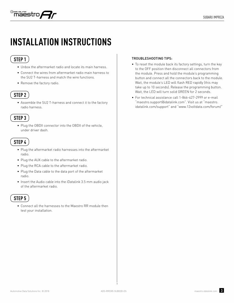
ADS-RR(SR)-SUB02B-DS maestro.idatalink.com
suBaRu impReZa
Automotive Data Solutions Inc. © 2018 3
INSTALLATION INSTRUCTIONS STEP 1
• Unbox the aftermarket radio and locate its main harness.
• Connect the wires from aftermarket radio main harness to the SU2 T-harness and match the wire functions.
• Remove the factory radio.
STEP 2
• Assemble the SU2 T-harness and connect it to the factory radio harness.
STEP 3• Plug the OBDII connector into the OBDII of the vehicle,
under driver dash.
STEP 4• Plug the aftermarket radio harnesses into the aftermarket
radio.
• Plug the AUX cable to the aftermarket radio.
• Plug the RCA cable to the aftermarket radio.
• Plug the Data cable to the data port of the aftermarket radio.
• Insert the Audio cable into the iDatalink 3.5 mm audio jack of the aftermarket radio.
STEP 5• Connect all the harnesses to the Maestro RR module then
test your installation.
TROUBLESHOOTING TIPS:
• To reset the module back its factory settings, turn the key to the OFF position then disconnect all connectors from the module. Press and hold the module’s programming button and connect all the connectors back to the module. Wait, the module’s LED will fl ash RED rapidly (this may take up to 10 seconds). Release the programming button. Wait, the LED will turn solid GREEN for 2 seconds.
• For technical assistance call 1-866-427-2999 or e-mail “[email protected]”. Visit us at “maestro.idatalink.com/support” and “www.12voltdata.com/forum/”
8

ADS-RR(SR)-SUB02B-DS maestro.idatalink.com
suBaRu impReZa
Automotive Data Solutions Inc. © 2018 4
8
BACKUP CAMBACKUP CAMCC
BB
AUXAUX
AA
D
GREENN.C.
MAESTRO RR MODULE
STEP 1
SU2 T-HARNESS
STEP 4
STEP 5
STARLINK (N.C.)
WIRING DIAGRAM
WIRES FROMVEHICLE
FACTORY RADIO HARNESSSTEP 2
STEP 3 OBDII CONNECTOR
DATACABLE
AUDIOCABLE
CONNECT TOAFTERMARKET RADIO
CONNECTIONS NOT REQUIRED
BLUE
NC
NC
YELLOW
MAINHARNESS
YELLOW - 12V (+)
BLACK - GROUNDRED - ACCESSORY (+)
BLUE/WHITE - AMP. TURN ON (+)
ORANGE - ILLUMINATION (+)PURPLE/WHITE - REVERSE LIGHT (+)LTGREEN - E-BRAKE (-)
BLUE - POWER ANTENNAPINK - VEHICLE SPEED
SEE RADIO WIREREFERENCECHARTFOR RADIO WIRECOLORS
WHITEWHITE/BLACKGRAYGRAY/BLACKGREENGREEN/BLACK
PURPLE/BLACKPURPLE
LF RCA INPUT
RF RCA INPUT
LR RCA INPUT
RR RCA INPUT

ADS-RR(SR)-SUB02B-DS maestro.idatalink.com
suBaRu impReZa
Automotive Data Solutions Inc. © 2018 5
RADIO WIRE REFERENCE CHART
WireDescription Polarity Wire Color on Maestro
T-Harness Wire Color on Alpine cable Wire Color on Kenwood cable Wire Color on Pioneer cable
Illumination (+) Orange N/A Orange/White Orange/White
Reverse Light (+) Purple/White Orange/White Purple/White Purple/White
E-Brake (-) Lt Green Yellow/Blue Lt Green Lt Green
VSS (vehicle speed sensor) (DATA) Pink Green/White N/A Pink
Power Antenna (+) Blue Blue Blue N/A

PROGRAMMED FIRMWAREADS-RR(SR)-SUB02B-DS
PRODUCTS REQUIREDiDatalink Maestro RR Radio Replacement InterfaceiDatalink Maestro SU2 Installation Harness
OPTIONAL ACCESSORIES
ACC-uSU2
Click here for: Radar Integration Installation GuideRadar Integration Owner’s Guide for Kenwood and JVC Radios
E L E C T R O N I C S
INSTALL GUIDESUBARU IMPREZA
WITh NAV AND hARMAN KARDON AND OEM CAMERA ON SECONDARy DISPLAy
2012-2014Retains steeRing wheel contRols, amplifieR and moRe!
NOTICE: Automotive Data Solutions Inc. (ADS) recommends having this installation performed by a certified technician. Logos and trademarks used here in are the properties of their respective owners.

ADS-RR(SR)-SUB02B-DS maestro.idatalink.com
suBaRu impReZa
Automotive Data Solutions Inc. © 2018 2
WELCOME
NEED hELP?
Congratulations on the purchase of your iDatalink Maestro RR Radio replacement solution. You are now a few simple steps away from enjoying your new car radio with enhanced features. Before starting your installation, please ensure that your iDatalink Maestro module is programmed with the correct fi rmware and that you carefully review the Installation Diagram and Vehicle Wire Refer-ence Chart.
Please note that Maestro RR will only retain functionalities that were originally available in the vehicle.
1 866 427-2999
maestro.idatalink.com/supportwww.12voltdata.com/forum
TABLE OF CONTENTS
Installation Instructions 3
Wiring Diagram 4
Radio Wire Reference Chart 5

ADS-RR(SR)-SUB02B-DS maestro.idatalink.com
suBaRu impReZa
Automotive Data Solutions Inc. © 2018 3
INSTALLATION INSTRUCTIONS STEP 1
• Unbox the aftermarket radio and locate its main harness.
• Connect the wires from aftermarket radio main harness to the SU2 T-harness and match the wire functions.
• Remove the factory radio.
STEP 2
• Assemble the SU2 T-harness and connect it to the factory radio harness.
STEP 3• Plug the OBDII connector into the OBDII of the vehicle,
under driver dash.
STEP 4• Plug the aftermarket radio harnesses into the aftermarket
radio.
• Plug the AUX cable to the aftermarket radio.
• Plug the RCA cable to the aftermarket radio.
• Plug the Data cable to the data port of the aftermarket radio.
• Insert the Audio cable into the iDatalink 3.5 mm audio jack of the aftermarket radio.
STEP 5• Connect all the harnesses to the Maestro RR module then
test your installation.
TROUBLESHOOTING TIPS:
• To reset the module back its factory settings, turn the key to the OFF position then disconnect all connectors from the module. Press and hold the module’s programming button and connect all the connectors back to the module. Wait, the module’s LED will fl ash RED rapidly (this may take up to 10 seconds). Release the programming button. Wait, the LED will turn solid GREEN for 2 seconds.
• For technical assistance call 1-866-427-2999 or e-mail “[email protected]”. Visit us at “maestro.idatalink.com/support” and “www.12voltdata.com/forum/”
3

ADS-RR(SR)-SUB02B-DS maestro.idatalink.com
suBaRu impReZa
Automotive Data Solutions Inc. © 2018 4
3
D
BACKUP CAMBACKUP CAMCC
AUXAUX
AA BB
MAESTRO RR MODULE
STEP 1
SU2 T-HARNESS
STEP 4
STEP 5
WIRING DIAGRAM
WIRES FROMVEHICLE
FACTORY RADIO HARNESSSTEP 2
STEP 3 OBDII CONNECTOR
CONNECT TO SECONDARYSCREEN HARNESS IF EQUIPPED
WITH A BACKUP CAMERA
DATACABLE
AUDIOCABLE
CONNECT TOAFTERMARKET RADIO
BLUE
GREENN.C.
N.C.
CONNECTIONS NOT REQUIRED
YELLOWN.C.
YELLOW
RED
MAINHARNESS
YELLOW - 12V (+)
BLACK - GROUNDRED - ACCESSORY (+)
BLUE/WHITE - AMP. TURN ON (+)
ORANGE - ILLUMINATION (+)PURPLE/WHITE - REVERSE LIGHT (+)LTGREEN - E-BRAKE (-)
BLUE - POWER ANTENNAPINK - VEHICLE SPEED
SEE RADIO WIREREFERENCECHARTFOR RADIO WIRECOLORS
WHITEWHITE/BLACKGRAYGRAY/BLACKGREENGREEN/BLACK
PURPLE/BLACKPURPLE
LF RCA INPUT
RF RCA INPUT
LR RCA INPUT
RR RCA INPUT
STARLINK (N.C.)

ADS-RR(SR)-SUB02B-DS maestro.idatalink.com
suBaRu impReZa
Automotive Data Solutions Inc. © 2018 5
RADIO WIRE REFERENCE CHART
WireDescription Polarity Wire Color on Maestro
T-Harness Wire Color on Alpine cable Wire Color on Kenwood cable Wire Color on Pioneer cable
Illumination (+) Orange N/A Orange/White Orange/White
Reverse Light (+) Purple/White Orange/White Purple/White Purple/White
E-Brake (-) Lt Green Yellow/Blue Lt Green Lt Green
VSS (vehicle speed sensor) (DATA) Pink Green/White N/A Pink
Power Antenna (+) Blue Blue Blue N/A

PROGRAMMED FIRMWAREADS-RR(SR)-SUB02B-DS
PRODUCTS REQUIREDiDatalink Maestro RR Radio Replacement InterfaceiDatalink Maestro SU2 Installation Harness
OPTIONAL ACCESSORIES
ACC-uSU2
Click here for: Radar Integration Installation GuideRadar Integration Owner’s Guide for Kenwood and JVC Radios
E L E C T R O N I C S
INSTALL GUIDESUBARU IMPREZA
WITh NAV AND OEM CAMERA ON RADIO
2012-2014Retains steeRing wheel contRols, amplifieR and moRe!
NOTICE: Automotive Data Solutions Inc. (ADS) recommends having this installation performed by a certified technician. Logos and trademarks used here in are the properties of their respective owners.

ADS-RR(SR)-SUB02B-DS maestro.idatalink.com
suBaRu impReZa with naV and oem cameRa on Radio 2012-2014
Automotive Data Solutions Inc. © 2018 2
WELCOME
NEED hELP?
Congratulations on the purchase of your iDatalink Maestro RR Radio replacement solution. You are now a few simple steps away from enjoying your new car radio with enhanced features. Before starting your installation, please ensure that your iDatalink Maestro module is programmed with the correct fi rmware and that you carefully review the Installation Diagram and Vehicle Wire Refer-ence Chart.
Please note that Maestro RR will only retain functionalities that were originally available in the vehicle.
1 866 427-2999
maestro.idatalink.com/supportwww.12voltdata.com/forum
TABLE OF CONTENTS
Installation Instructions 3
Wiring Diagram 4
Radio Wire Reference Chart 5
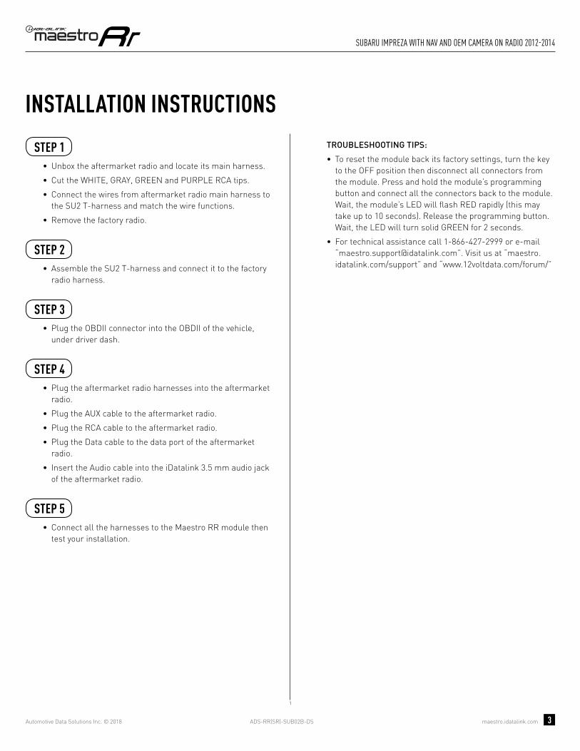
ADS-RR(SR)-SUB02B-DS maestro.idatalink.com
suBaRu impReZa with naV and oem cameRa on Radio 2012-2014
Automotive Data Solutions Inc. © 2018 3
INSTALLATION INSTRUCTIONS STEP 1
• Unbox the aftermarket radio and locate its main harness.
• Cut the WHITE, GRAY, GREEN and PURPLE RCA tips.
• Connect the wires from aftermarket radio main harness to the SU2 T-harness and match the wire functions.
• Remove the factory radio.
STEP 2
• Assemble the SU2 T-harness and connect it to the factory radio harness.
STEP 3• Plug the OBDII connector into the OBDII of the vehicle,
under driver dash.
STEP 4• Plug the aftermarket radio harnesses into the aftermarket
radio.
• Plug the AUX cable to the aftermarket radio.
• Plug the RCA cable to the aftermarket radio.
• Plug the Data cable to the data port of the aftermarket radio.
• Insert the Audio cable into the iDatalink 3.5 mm audio jack of the aftermarket radio.
STEP 5• Connect all the harnesses to the Maestro RR module then
test your installation.
TROUBLESHOOTING TIPS:
• To reset the module back its factory settings, turn the key to the OFF position then disconnect all connectors from the module. Press and hold the module’s programming button and connect all the connectors back to the module. Wait, the module’s LED will fl ash RED rapidly (this may take up to 10 seconds). Release the programming button. Wait, the LED will turn solid GREEN for 2 seconds.
• For technical assistance call 1-866-427-2999 or e-mail “[email protected]”. Visit us at “maestro.idatalink.com/support” and “www.12voltdata.com/forum/”
1

ADS-RR(SR)-SUB02B-DS maestro.idatalink.com
suBaRu impReZa with naV and oem cameRa on Radio 2012-2014
Automotive Data Solutions Inc. © 2018 4
1
BACKUP CAMBACKUP CAMCC
AUXAUX
AA
D
BB
MAESTRO RR MODULE
CUT AND REMOVE THE RCA JACKS
STEP 1
MAINHARNESS
SU2 T-HARNESS
WHITE - LF SPEAKER (+)WHITE/BLACK - LF SPEAKER (-)GRAY - RF SPEAKER (+)GRAY/BLACK - RF SPEAKER (-)GREEN - LR SPEAKER (+)GREEN/BLACK - LR SPEAKER (-)
PURPLE/BLACK - RR SPEAKER (-)
YELLOW - 12V (+)
BLACK - GROUNDRED - ACCESSORY (+)
BLUE/WHITE - AMP. TURN ON (+)
PURPLE - RR SPEAKER (+)
STEP 4
STEP 5
ORANGE - ILLUMINATION (+)PURPLE/WHITE - REVERSE LIGHT (+)LTGREEN - E-BRAKE (-)
BLUE - POWER ANTENNAPINK - VEHICLE SPEED
WIRING DIAGRAM
WIRES FROMVEHICLE
FACTORY RADIO HARNESSSTEP 2
STEP 3 OBDII CONNECTOR
SEE RADIO WIREREFERENCECHARTFOR RADIO WIRECOLORS
DATACABLE
AUDIOCABLE
CONNECT TOAFTERMARKET RADIO
BLUE
GREENNC
NC
NC
NC
CONNECTIONS NOT REQUIRED
YELLOW
STARLINK (N.C.)

ADS-RR(SR)-SUB02B-DS maestro.idatalink.com
suBaRu impReZa with naV and oem cameRa on Radio 2012-2014
Automotive Data Solutions Inc. © 2018 5
RADIO WIRE REFERENCE CHART
WireDescription Polarity Wire Color on Maestro
T-Harness Wire Color on Alpine cable Wire Color on Kenwood cable Wire Color on Pioneer cable
Illumination (+) Orange N/A Orange/White Orange/White
Reverse Light (+) Purple/White Orange/White Purple/White Purple/White
E-Brake (-) Lt Green Yellow/Blue Lt Green Lt Green
VSS (vehicle speed sensor) (DATA) Pink Green/White N/A Pink
Power Antenna (+) Blue Blue Blue N/A

PROGRAMMED FIRMWAREADS-RR(SR)-SUB02B-DS
PRODUCTS REQUIREDiDatalink Maestro RR Radio Replacement InterfaceiDatalink Maestro SU2 Installation Harness
OPTIONAL ACCESSORIES
ACC-uSU2
Click here for: Radar Integration Installation GuideRadar Integration Owner’s Guide for Kenwood and JVC Radios
E L E C T R O N I C S
INSTALL GUIDESUBARU IMPREZA
WITh NAV AND OEM CAMERA ON SECONDARy DISPLAy
2012-2014Retains steeRing wheel contRols, amplifieR and moRe!
NOTICE: Automotive Data Solutions Inc. (ADS) recommends having this installation performed by a certified technician. Logos and trademarks used here in are the properties of their respective owners.

ADS-RR(SR)-SUB02B-DS maestro.idatalink.com
suBaRu impReZa
Automotive Data Solutions Inc. © 2018 2
WELCOME
NEED hELP?
Congratulations on the purchase of your iDatalink Maestro RR Radio replacement solution. You are now a few simple steps away from enjoying your new car radio with enhanced features. Before starting your installation, please ensure that your iDatalink Maestro module is programmed with the correct fi rmware and that you carefully review the Installation Diagram and Vehicle Wire Refer-ence Chart.
Please note that Maestro RR will only retain functionalities that were originally available in the vehicle.
1 866 427-2999
maestro.idatalink.com/supportwww.12voltdata.com/forum
TABLE OF CONTENTS
Installation Instructions 3
Wiring Diagram 4
Radio Wire Reference Chart 5
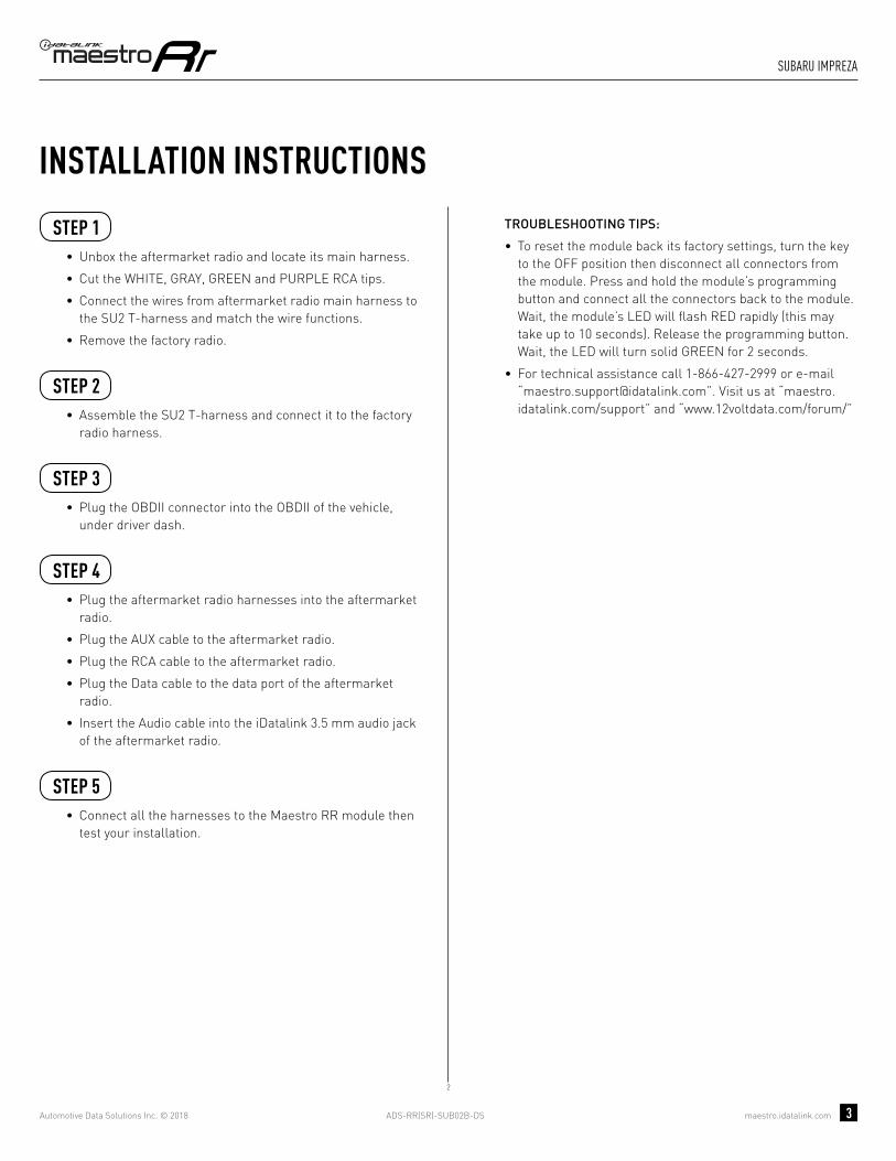
ADS-RR(SR)-SUB02B-DS maestro.idatalink.com
suBaRu impReZa
Automotive Data Solutions Inc. © 2018 3
INSTALLATION INSTRUCTIONS STEP 1
• Unbox the aftermarket radio and locate its main harness.
• Cut the WHITE, GRAY, GREEN and PURPLE RCA tips.
• Connect the wires from aftermarket radio main harness to the SU2 T-harness and match the wire functions.
• Remove the factory radio.
STEP 2
• Assemble the SU2 T-harness and connect it to the factory radio harness.
STEP 3• Plug the OBDII connector into the OBDII of the vehicle,
under driver dash.
STEP 4• Plug the aftermarket radio harnesses into the aftermarket
radio.
• Plug the AUX cable to the aftermarket radio.
• Plug the RCA cable to the aftermarket radio.
• Plug the Data cable to the data port of the aftermarket radio.
• Insert the Audio cable into the iDatalink 3.5 mm audio jack of the aftermarket radio.
STEP 5• Connect all the harnesses to the Maestro RR module then
test your installation.
TROUBLESHOOTING TIPS:
• To reset the module back its factory settings, turn the key to the OFF position then disconnect all connectors from the module. Press and hold the module’s programming button and connect all the connectors back to the module. Wait, the module’s LED will fl ash RED rapidly (this may take up to 10 seconds). Release the programming button. Wait, the LED will turn solid GREEN for 2 seconds.
• For technical assistance call 1-866-427-2999 or e-mail “[email protected]”. Visit us at “maestro.idatalink.com/support” and “www.12voltdata.com/forum/”
2

ADS-RR(SR)-SUB02B-DS maestro.idatalink.com
suBaRu impReZa
Automotive Data Solutions Inc. © 2018 4
2
D
BACKUP CAMBACKUP CAMCC
AUXAUX
AA BB
MAESTRO RR MODULE
CUT AND REMOVE THE RCA JACKS
STEP 1
MAINHARNESS
SU2 T-HARNESS
WHITE - LF SPEAKER (+)WHITE/BLACK - LF SPEAKER (-)GRAY - RF SPEAKER (+)GRAY/BLACK - RF SPEAKER (-)GREEN - LR SPEAKER (+)GREEN/BLACK - LR SPEAKER (-)
PURPLE/BLACK - RR SPEAKER (-)
YELLOW - 12V (+)
BLACK - GROUNDRED - ACCESSORY (+)
BLUE/WHITE - AMP. TURN ON (+)
PURPLE - RR SPEAKER (+)
STEP 4
STEP 5
ORANGE - ILLUMINATION (+)PURPLE/WHITE - REVERSE LIGHT (+)LTGREEN - E-BRAKE (-)
BLUE - POWER ANTENNAPINK - VEHICLE SPEED
WIRING DIAGRAM
WIRES FROMVEHICLE
FACTORY RADIO HARNESSSTEP 2
STEP 3 OBDII CONNECTOR
SEE RADIO WIREREFERENCECHARTFOR RADIO WIRECOLORS
CONNECT TO SECONDARYSCREEN HARNESS IF EQUIPPED
WITH A BACKUP CAMERA
DATACABLE
AUDIOCABLE
CONNECT TOAFTERMARKET RADIO
BLUE
GREENN.C.
N.C.
CONNECTIONS NOT REQUIRED
YELLOWN.C.
YELLOW
RED
STARLINK (N.C.)
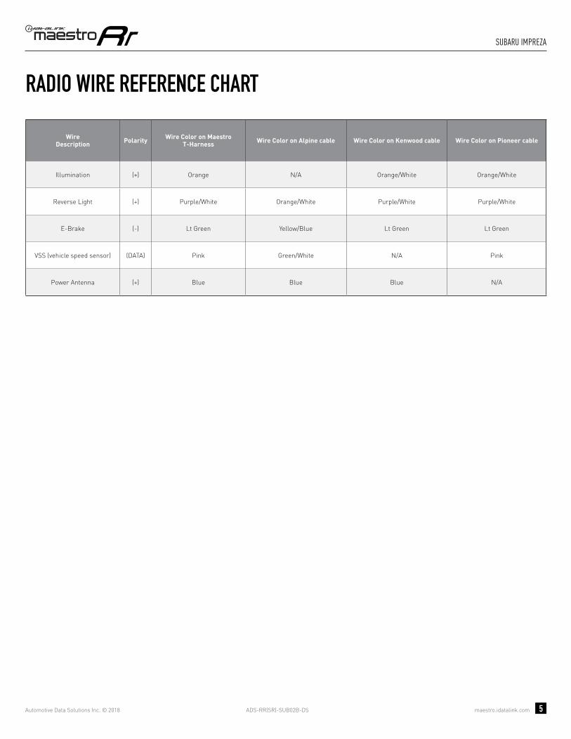
ADS-RR(SR)-SUB02B-DS maestro.idatalink.com
suBaRu impReZa
Automotive Data Solutions Inc. © 2018 5
RADIO WIRE REFERENCE CHART
WireDescription Polarity Wire Color on Maestro
T-Harness Wire Color on Alpine cable Wire Color on Kenwood cable Wire Color on Pioneer cable
Illumination (+) Orange N/A Orange/White Orange/White
Reverse Light (+) Purple/White Orange/White Purple/White Purple/White
E-Brake (-) Lt Green Yellow/Blue Lt Green Lt Green
VSS (vehicle speed sensor) (DATA) Pink Green/White N/A Pink
Power Antenna (+) Blue Blue Blue N/A

PROGRAMMED FIRMWAREADS-RR(SR)-SUB02B-DS
PRODUCTS REQUIREDiDatalink Maestro RR Radio Replacement InterfaceiDatalink Maestro SU2 Installation Harness
OPTIONAL ACCESSORIES
ACC-uSU2
Click here for: Radar Integration Installation GuideRadar Integration Owner’s Guide for Kenwood and JVC Radios
E L E C T R O N I C S
INSTALL GUIDESUBARU LEGACy
WITh 6.2 INCh SCREEN
2015-2017Retains steeRing wheel contRols, amplifieR and moRe!
NOTICE: Automotive Data Solutions Inc. (ADS) recommends having this installation performed by a certified technician. Logos and trademarks used here in are the properties of their respective owners.

ADS-RR(SR)-SUB02B-DS maestro.idatalink.com
suBaRu legacy with 6.2 inch scReen 2015-2017
Automotive Data Solutions Inc. © 2018 2
WELCOME
NEED hELP?
Congratulations on the purchase of your iDatalink Maestro RR Radio replacement solution. You are now a few simple steps away from enjoying your new car radio with enhanced features. Before starting your installation, please ensure that your iDatalink Maestro module is programmed with the correct fi rmware and that you carefully review the Installation Diagram and Vehicle Wire Refer-ence Chart.
Please note that Maestro RR will only retain functionalities that were originally available in the vehicle.
1 866 427-2999
maestro.idatalink.com/supportwww.12voltdata.com/forum
TABLE OF CONTENTS
Installation Instructions 3
Wiring Diagram 4
Radio Wire Reference Chart 5

ADS-RR(SR)-SUB02B-DS maestro.idatalink.com
suBaRu legacy with 6.2 inch scReen 2015-2017
Automotive Data Solutions Inc. © 2018 3
INSTALLATION INSTRUCTIONS STEP 1
• Unbox the aftermarket radio and locate its main harness.
• Cut the WHITE, GRAY, GREEN and PURPLE RCA tips.
• Connect the wires from aftermarket radio main harness to the SU2 T-harness and match the wire functions.
• Remove the factory radio.
STEP 2
• Assemble the SU2 T-harness and connect it to the factory radio harness.
STEP 3Note: Connection required if the vehicle is equipped with Starlink telematics and a SOS button.
• Connect the BROWN Starlink wire to PINK or WHITE/BLUE (pin 8) of the 8 pin connector behind the OEM Radio.
STEP 4• Plug the OBDII connector into the OBDII of the vehicle,
under driver dash.
STEP 5• Plug the aftermarket radio harnesses into the aftermarket
radio.
• Plug the AUX cable to the aftermarket radio.
• Plug the RCA cable to the aftermarket radio.
• Plug the Data cable to the data port of the aftermarket radio.
• Insert the Audio cable into the iDatalink 3.5 mm audio jack of the aftermarket radio.
STEP 6• Connect all the harnesses to the Maestro RR module then
test your installation.
TROUBLESHOOTING TIPS:
• To reset the module back its factory settings, turn the key to the OFF position then disconnect all connectors from the module. Press and hold the module’s programming button and connect all the connectors back to the module. Wait, the module’s LED will fl ash RED rapidly (this may take up to 10 seconds). Release the programming button. Wait, the LED will turn solid GREEN for 2 seconds.
• For technical assistance call 1-866-427-2999 or e-mail “[email protected]”. Visit us at “maestro.idatalink.com/support” and “www.12voltdata.com/forum/”
4

ADS-RR(SR)-SUB02B-DS maestro.idatalink.com
suBaRu legacy with 6.2 inch scReen 2015-2017
Automotive Data Solutions Inc. © 2018 4
4
BACKUP CAMBACKUP CAMCC
AUXAUX
AA
D
BB
MAESTRO RR MODULE
CUT AND REMOVE THE RCA JACKS
STEP 1
MAINHARNESS
SU2 T-HARNESS
WHITE - LF SPEAKER (+)WHITE/BLACK - LF SPEAKER (-)GRAY - RF SPEAKER (+)GRAY/BLACK - RF SPEAKER (-)GREEN - LR SPEAKER (+)GREEN/BLACK - LR SPEAKER (-)
PURPLE/BLACK - RR SPEAKER (-)
YELLOW - 12V (+)
BLACK - GROUNDRED - ACCESSORY (+)
BLUE/WHITE - AMP. TURN ON (+)
PURPLE - RR SPEAKER (+)
STEP 5
STEP 6
ORANGE - ILLUMINATION (+)PURPLE/WHITE - REVERSE LIGHT (+)LTGREEN - E-BRAKE (-)
BLUE - POWER ANTENNAPINK - VEHICLE SPEED
WIRING DIAGRAM
WIRES FROMVEHICLE
FACTORY RADIO HARNESSSTEP 2
STEP 4 OBDII CONNECTOR
SEE RADIO WIREREFERENCECHARTFOR RADIO WIRECOLORS
DATACABLE
AUDIOCABLE
CONNECT TOAFTERMARKET RADIO
BLUE
GREENN.C.
CONNECTIONS NOT REQUIRED
YELLOW
STARLINK PINK OR WHITE/BLUE - 08
8 PIN CONNECTOR BEHIND OEM RADIOSTEP 3

ADS-RR(SR)-SUB02B-DS maestro.idatalink.com
suBaRu legacy with 6.2 inch scReen 2015-2017
Automotive Data Solutions Inc. © 2018 5
RADIO WIRE REFERENCE CHART
WireDescription Polarity Wire Color on Maestro
T-Harness Wire Color on Alpine cable Wire Color on Kenwood cable Wire Color on Pioneer cable
Illumination (+) Orange N/A Orange/White Orange/White
Reverse Light (+) Purple/White Orange/White Purple/White Purple/White
E-Brake (-) Lt Green Yellow/Blue Lt Green Lt Green
VSS (vehicle speed sensor) (DATA) Pink Green/White N/A Pink
Power Antenna (+) Blue Blue Blue N/A

PROGRAMMED FIRMWAREADS-RR(SR)-SUB02B-DS
PRODUCTS REQUIREDiDatalink Maestro RR Radio Replacement InterfaceiDatalink Maestro SU2 Installation Harness
OPTIONAL ACCESSORIES
ACC-uSU2
Click here for: Radar Integration Installation GuideRadar Integration Owner’s Guide for Kenwood and JVC Radios
E L E C T R O N I C S
INSTALL GUIDESUBARU LEGACy
WITh 6.2 INCh SCREEN AND hARMAN KARDON
2015-2017Retains steeRing wheel contRols, amplifieR and moRe!
NOTICE: Automotive Data Solutions Inc. (ADS) recommends having this installation performed by a certified technician. Logos and trademarks used here in are the properties of their respective owners.

ADS-RR(SR)-SUB02B-DS maestro.idatalink.com
suBaRu legacy with 6.2 inch scReen and haRman KaRdon
Automotive Data Solutions Inc. © 2018 2
WELCOME
NEED hELP?
Congratulations on the purchase of your iDatalink Maestro RR Radio replacement solution. You are now a few simple steps away from enjoying your new car radio with enhanced features. Before starting your installation, please ensure that your iDatalink Maestro module is programmed with the correct fi rmware and that you carefully review the Installation Diagram and Vehicle Wire Refer-ence Chart.
Please note that Maestro RR will only retain functionalities that were originally available in the vehicle.
1 866 427-2999
maestro.idatalink.com/supportwww.12voltdata.com/forum
TABLE OF CONTENTS
Installation Instructions 3
Wiring Diagram 4
Radio Wire Reference Chart 5

ADS-RR(SR)-SUB02B-DS maestro.idatalink.com
suBaRu legacy with 6.2 inch scReen and haRman KaRdon
Automotive Data Solutions Inc. © 2018 3
INSTALLATION INSTRUCTIONS STEP 1
• Unbox the aftermarket radio and locate its main harness.
• Connect the wires from aftermarket radio main harness to the SU2 T-harness and match the wire functions.
• Remove the factory radio.
STEP 2
• Assemble the SU2 T-harness and connect it to the factory radio harness.
STEP 3Note: Connection required if the vehicle is equipped with Starlink telematics and a SOS button.
• Connect the BROWN Starlink wire to PINK or WHITE/BLUE (pin 8) of the 8 pin connector behind the OEM Radio.
STEP 4• Plug the OBDII connector into the OBDII of the vehicle,
under driver dash.
STEP 5• Plug the aftermarket radio harnesses into the aftermarket
radio.
• Plug the AUX cable to the aftermarket radio.
• Plug the RCA cable to the aftermarket radio.
• Plug the Data cable to the data port of the aftermarket radio.
• Insert the Audio cable into the iDatalink 3.5 mm audio jack of the aftermarket radio.
STEP 6• Connect all the harnesses to the Maestro RR module then
test your installation.
TROUBLESHOOTING TIPS:
• To reset the module back its factory settings, turn the key to the OFF position then disconnect all connectors from the module. Press and hold the module’s programming button and connect all the connectors back to the module. Wait, the module’s LED will fl ash RED rapidly (this may take up to 10 seconds). Release the programming button. Wait, the LED will turn solid GREEN for 2 seconds.
• For technical assistance call 1-866-427-2999 or e-mail “[email protected]”. Visit us at “maestro.idatalink.com/support” and “www.12voltdata.com/forum/”
6

ADS-RR(SR)-SUB02B-DS maestro.idatalink.com
suBaRu legacy with 6.2 inch scReen and haRman KaRdon
Automotive Data Solutions Inc. © 2018 4
6
BACKUP CAMBACKUP CAMCC
AUXAUX
AA
D
BB
STARLINK PINK OR WHITE/BLUE - 08
8 PIN CONNECTOR BEHIND OEM RADIOSTEP 3
MAESTRO RR MODULE
STEP 1
SU2 T-HARNESS
STEP 5
STEP 6
WIRING DIAGRAM
WIRES FROMVEHICLE
FACTORY RADIO HARNESSSTEP 2
STEP 4 OBDII CONNECTOR
DATACABLE
AUDIOCABLE
CONNECT TOAFTERMARKET RADIO
BLUE
CONNECTIONS NOT REQUIRED
YELLOW
MAINHARNESS
YELLOW - 12V (+)
BLACK - GROUNDRED - ACCESSORY (+)
BLUE/WHITE - AMP. TURN ON (+)
ORANGE - ILLUMINATION (+)PURPLE/WHITE - REVERSE LIGHT (+)LTGREEN - E-BRAKE (-)
BLUE - POWER ANTENNAPINK - VEHICLE SPEED
SEE RADIO WIREREFERENCECHARTFOR RADIO WIRECOLORS
WHITEWHITE/BLACKGRAYGRAY/BLACKGREENGREEN/BLACK
PURPLE/BLACKPURPLE
LF RCA INPUT
RF RCA INPUT
LR RCA INPUT
RR RCA INPUT
RCA CABLES
GREENN.C.

ADS-RR(SR)-SUB02B-DS maestro.idatalink.com
suBaRu legacy with 6.2 inch scReen and haRman KaRdon
Automotive Data Solutions Inc. © 2018 5
RADIO WIRE REFERENCE CHART
WireDescription Polarity Wire Color on Maestro
T-Harness Wire Color on Alpine cable Wire Color on Kenwood cable Wire Color on Pioneer cable
Illumination (+) Orange N/A Orange/White Orange/White
Reverse Light (+) Purple/White Orange/White Purple/White Purple/White
E-Brake (-) Lt Green Yellow/Blue Lt Green Lt Green
VSS (vehicle speed sensor) (DATA) Pink Green/White N/A Pink
Power Antenna (+) Blue Blue Blue N/A

PROGRAMMED FIRMWAREADS-RR(SR)-SUB02B-DS
PRODUCTS REQUIREDiDatalink Maestro RR Radio Replacement InterfaceiDatalink Maestro SU2 Installation Harness
OPTIONAL ACCESSORIES
ACC-uSU2
Click here for: Radar Integration Installation GuideRadar Integration Owner’s Guide for Kenwood and JVC Radios
E L E C T R O N I C S
INSTALL GUIDESUBARU LEGACy
WITh 7 INCh SCREEN
2015-2017Retains steeRing wheel contRols, amplifieR and moRe!
NOTICE: Automotive Data Solutions Inc. (ADS) recommends having this installation performed by a certified technician. Logos and trademarks used here in are the properties of their respective owners.

ADS-RR(SR)-SUB02B-DS maestro.idatalink.com
suBaRu legacy with 7 inch scReen 2015-2017
Automotive Data Solutions Inc. © 2018 2
WELCOME
NEED hELP?
Congratulations on the purchase of your iDatalink Maestro RR Radio replacement solution. You are now a few simple steps away from enjoying your new car radio with enhanced features. Before starting your installation, please ensure that your iDatalink Maestro module is programmed with the correct fi rmware and that you carefully review the Installation Diagram and Vehicle Wire Refer-ence Chart.
Please note that Maestro RR will only retain functionalities that were originally available in the vehicle.
1 866 427-2999
maestro.idatalink.com/supportwww.12voltdata.com/forum
TABLE OF CONTENTS
Installation Instructions 3
Wiring Diagram 4
Radio Wire Reference Chart 5

ADS-RR(SR)-SUB02B-DS maestro.idatalink.com
suBaRu legacy with 7 inch scReen 2015-2017
Automotive Data Solutions Inc. © 2018 3
INSTALLATION INSTRUCTIONS STEP 1
• Unbox the aftermarket radio and locate its main harness.
• Cut the WHITE, GRAY, GREEN and PURPLE RCA tips.
• Connect the wires from aftermarket radio main harness to the SU2 T-harness and match the wire functions.
• Remove the factory radio.
STEP 2
• Assemble the SU2 T-harness and connect it to the factory radio harness.
STEP 3Note: Connection required if the vehicle is equipped with Starlink telematics and a SOS button.
• Connect the BROWN Starlink wire to PINK or WHITE/BLUE (pin 8) of the 8 pin connector behind the OEM Radio.
STEP 4• Plug the OBDII connector into the OBDII of the vehicle,
under driver dash.
STEP 5• Plug the aftermarket radio harnesses into the aftermarket
radio.
• Plug the AUX cable to the aftermarket radio.
• Plug the RCA cable to the aftermarket radio.
• Plug the Data cable to the data port of the aftermarket radio.
• Insert the Audio cable into the iDatalink 3.5 mm audio jack of the aftermarket radio.
STEP 6• Connect all the harnesses to the Maestro RR module then
test your installation.
TROUBLESHOOTING TIPS:
• To reset the module back its factory settings, turn the key to the OFF position then disconnect all connectors from the module. Press and hold the module’s programming button and connect all the connectors back to the module. Wait, the module’s LED will fl ash RED rapidly (this may take up to 10 seconds). Release the programming button. Wait, the LED will turn solid GREEN for 2 seconds.
• For technical assistance call 1-866-427-2999 or e-mail “[email protected]”. Visit us at “maestro.idatalink.com/support” and “www.12voltdata.com/forum/”
5

ADS-RR(SR)-SUB02B-DS maestro.idatalink.com
suBaRu legacy with 7 inch scReen 2015-2017
Automotive Data Solutions Inc. © 2018 4
5
BACKUP CAMBACKUP CAMCC
AA
AUXAUX
BB
D
GREENN.C.
MAESTRO RR MODULE
CUT AND REMOVE THE RCA JACKS
STEP 1
MAINHARNESS
SU2 T-HARNESS
WHITE - LF SPEAKER (+)WHITE/BLACK - LF SPEAKER (-)GRAY - RF SPEAKER (+)GRAY/BLACK - RF SPEAKER (-)GREEN - LR SPEAKER (+)GREEN/BLACK - LR SPEAKER (-)
PURPLE/BLACK - RR SPEAKER (-)
YELLOW - 12V (+)
BLACK - GROUNDRED - ACCESSORY (+)
BLUE/WHITE - AMP. TURN ON (+)
PURPLE - RR SPEAKER (+)
STEP 5
STEP 6
ORANGE - ILLUMINATION (+)PURPLE/WHITE - REVERSE LIGHT (+)LTGREEN - E-BRAKE (-)
BLUE - POWER ANTENNA
STARLINK PINK OR WHITE/BLUE - 08
PINK - VEHICLE SPEED
WIRING DIAGRAM
WIRES FROMVEHICLE
FACTORY RADIO HARNESS
8 PIN CONNECTOR BEHIND OEM RADIO
STEP 2
STEP 4
STEP 3
OBDII CONNECTOR
SEE RADIO WIREREFERENCECHARTFOR RADIO WIRECOLORS
DATACABLE
AUDIOCABLE
CONNECT TOAFTERMARKET RADIO
CONNECTIONS NOT REQUIRED
BLUE
NC
NC
YELLOW

ADS-RR(SR)-SUB02B-DS maestro.idatalink.com
suBaRu legacy with 7 inch scReen 2015-2017
Automotive Data Solutions Inc. © 2018 5
RADIO WIRE REFERENCE CHART
WireDescription Polarity Wire Color on Maestro
T-Harness Wire Color on Alpine cable Wire Color on Kenwood cable Wire Color on Pioneer cable
Illumination (+) Orange N/A Orange/White Orange/White
Reverse Light (+) Purple/White Orange/White Purple/White Purple/White
E-Brake (-) Lt Green Yellow/Blue Lt Green Lt Green
VSS (vehicle speed sensor) (DATA) Pink Green/White N/A Pink
Power Antenna (+) Blue Blue Blue N/A

PROGRAMMED FIRMWAREADS-RR(SR)-SUB02B-DS
PRODUCTS REQUIREDiDatalink Maestro RR Radio Replacement InterfaceiDatalink Maestro SU2 Installation Harness
OPTIONAL ACCESSORIES
ACC-uSU2
Click here for: Radar Integration Installation GuideRadar Integration Owner’s Guide for Kenwood and JVC Radios
E L E C T R O N I C S
INSTALL GUIDESUBARU LEGACy
WITh 7 INCh SCREEN AND hARMAN KARDON
2015-2017Retains steeRing wheel contRols, amplifieR and moRe!
NOTICE: Automotive Data Solutions Inc. (ADS) recommends having this installation performed by a certified technician. Logos and trademarks used here in are the properties of their respective owners.

ADS-RR(SR)-SUB02B-DS maestro.idatalink.com
suBaRu legacy with 7 inch scReen and haRman KaRdon
Automotive Data Solutions Inc. © 2018 2
WELCOME
NEED hELP?
Congratulations on the purchase of your iDatalink Maestro RR Radio replacement solution. You are now a few simple steps away from enjoying your new car radio with enhanced features. Before starting your installation, please ensure that your iDatalink Maestro module is programmed with the correct fi rmware and that you carefully review the Installation Diagram and Vehicle Wire Refer-ence Chart.
Please note that Maestro RR will only retain functionalities that were originally available in the vehicle.
1 866 427-2999
maestro.idatalink.com/supportwww.12voltdata.com/forum
TABLE OF CONTENTS
Installation Instructions 3
Wiring Diagram 4
Radio Wire Reference Chart 5

ADS-RR(SR)-SUB02B-DS maestro.idatalink.com
suBaRu legacy with 7 inch scReen and haRman KaRdon
Automotive Data Solutions Inc. © 2018 3
INSTALLATION INSTRUCTIONS STEP 1
• Unbox the aftermarket radio and locate its main harness.
• Connect the wires from aftermarket radio main harness to the SU2 T-harness and match the wire functions.
• Remove the factory radio.
STEP 2
• Assemble the SU2 T-harness and connect it to the factory radio harness.
STEP 3Note: Connection required if the vehicle is equipped with Starlink telematics and a SOS button.
• Connect the BROWN Starlink wire to PINK or WHITE/BLUE (pin 8) of the 8 pin connector behind the OEM Radio.
STEP 4• Plug the OBDII connector into the OBDII of the vehicle,
under driver dash.
STEP 5• Plug the aftermarket radio harnesses into the aftermarket
radio.
• Plug the AUX cable to the aftermarket radio.
• Plug the RCA cable to the aftermarket radio.
• Plug the Data cable to the data port of the aftermarket radio.
• Insert the Audio cable into the iDatalink 3.5 mm audio jack of the aftermarket radio.
STEP 6• Connect all the harnesses to the Maestro RR module then
test your installation.
TROUBLESHOOTING TIPS:
• To reset the module back its factory settings, turn the key to the OFF position then disconnect all connectors from the module. Press and hold the module’s programming button and connect all the connectors back to the module. Wait, the module’s LED will fl ash RED rapidly (this may take up to 10 seconds). Release the programming button. Wait, the LED will turn solid GREEN for 2 seconds.
• For technical assistance call 1-866-427-2999 or e-mail “[email protected]”. Visit us at “maestro.idatalink.com/support” and “www.12voltdata.com/forum/”
7
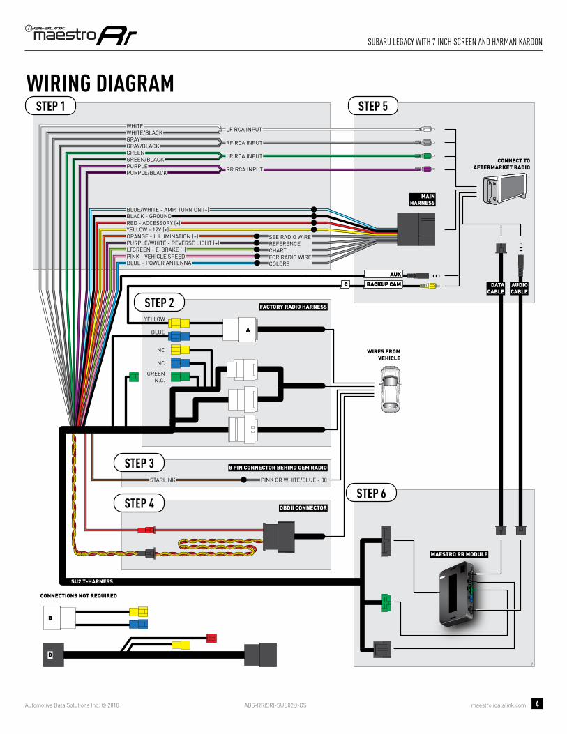
ADS-RR(SR)-SUB02B-DS maestro.idatalink.com
suBaRu legacy with 7 inch scReen and haRman KaRdon
Automotive Data Solutions Inc. © 2018 4
7
BACKUP CAMBACKUP CAMCC
AA
AUXAUX
BB
D
GREENN.C.
MAESTRO RR MODULE
STEP 1
SU2 T-HARNESS
STEP 5
STEP 6STARLINK PINK OR WHITE/BLUE - 08
WIRING DIAGRAM
WIRES FROMVEHICLE
FACTORY RADIO HARNESS
8 PIN CONNECTOR BEHIND OEM RADIO
STEP 2
STEP 4
STEP 3
OBDII CONNECTOR
DATACABLE
AUDIOCABLE
CONNECT TOAFTERMARKET RADIO
CONNECTIONS NOT REQUIRED
BLUE
NC
NC
YELLOW
MAINHARNESS
YELLOW - 12V (+)
BLACK - GROUNDRED - ACCESSORY (+)
BLUE/WHITE - AMP. TURN ON (+)
ORANGE - ILLUMINATION (+)PURPLE/WHITE - REVERSE LIGHT (+)LTGREEN - E-BRAKE (-)
BLUE - POWER ANTENNAPINK - VEHICLE SPEED
SEE RADIO WIREREFERENCECHARTFOR RADIO WIRECOLORS
WHITEWHITE/BLACKGRAYGRAY/BLACKGREENGREEN/BLACK
PURPLE/BLACKPURPLE
LF RCA INPUT
RF RCA INPUT
LR RCA INPUT
RR RCA INPUT

ADS-RR(SR)-SUB02B-DS maestro.idatalink.com
suBaRu legacy with 7 inch scReen and haRman KaRdon
Automotive Data Solutions Inc. © 2018 5
RADIO WIRE REFERENCE CHART
WireDescription Polarity Wire Color on Maestro
T-Harness Wire Color on Alpine cable Wire Color on Kenwood cable Wire Color on Pioneer cable
Illumination (+) Orange N/A Orange/White Orange/White
Reverse Light (+) Purple/White Orange/White Purple/White Purple/White
E-Brake (-) Lt Green Yellow/Blue Lt Green Lt Green
VSS (vehicle speed sensor) (DATA) Pink Green/White N/A Pink
Power Antenna (+) Blue Blue Blue N/A

PROGRAMMED FIRMWAREADS-RR(SR)-SUB02B-DS
PRODUCTS REQUIREDiDatalink Maestro RR Radio Replacement InterfaceiDatalink Maestro SU2 Installation Harness
OPTIONAL ACCESSORIES
ACC-uSU2
Click here for: Radar Integration Installation GuideRadar Integration Owner’s Guide for Kenwood and JVC Radios
E L E C T R O N I C S
INSTALL GUIDESUBARU OUTBACK
WITh 6.2 INCh SCREEN
2015-2017Retains steeRing wheel contRols, amplifieR and moRe!
NOTICE: Automotive Data Solutions Inc. (ADS) recommends having this installation performed by a certified technician. Logos and trademarks used here in are the properties of their respective owners.

ADS-RR(SR)-SUB02B-DS maestro.idatalink.com
suBaRu outBacK with 6.2 inch scReen 2015-2017
Automotive Data Solutions Inc. © 2018 2
WELCOME
NEED hELP?
Congratulations on the purchase of your iDatalink Maestro RR Radio replacement solution. You are now a few simple steps away from enjoying your new car radio with enhanced features. Before starting your installation, please ensure that your iDatalink Maestro module is programmed with the correct fi rmware and that you carefully review the Installation Diagram and Vehicle Wire Refer-ence Chart.
Please note that Maestro RR will only retain functionalities that were originally available in the vehicle.
1 866 427-2999
maestro.idatalink.com/supportwww.12voltdata.com/forum
TABLE OF CONTENTS
Installation Instructions 3
Wiring Diagram 4
Radio Wire Reference Chart 5

ADS-RR(SR)-SUB02B-DS maestro.idatalink.com
suBaRu outBacK with 6.2 inch scReen 2015-2017
Automotive Data Solutions Inc. © 2018 3
INSTALLATION INSTRUCTIONS STEP 1
• Unbox the aftermarket radio and locate its main harness.
• Cut the WHITE, GRAY, GREEN and PURPLE RCA tips.
• Connect the wires from aftermarket radio main harness to the SU2 T-harness and match the wire functions.
• Remove the factory radio.
STEP 2
• Assemble the SU2 T-harness and connect it to the factory radio harness.
STEP 3Note: Connection required if the vehicle is equipped with Starlink telematics and a SOS button.
• Connect the BROWN Starlink wire to PINK or WHITE/BLUE (pin 8) of the 8 pin connector behind the OEM Radio.
STEP 4• Plug the OBDII connector into the OBDII of the vehicle,
under driver dash.
STEP 5• Plug the aftermarket radio harnesses into the aftermarket
radio.
• Plug the AUX cable to the aftermarket radio.
• Plug the RCA cable to the aftermarket radio.
• Plug the Data cable to the data port of the aftermarket radio.
• Insert the Audio cable into the iDatalink 3.5 mm audio jack of the aftermarket radio.
STEP 6• Connect all the harnesses to the Maestro RR module then
test your installation.
TROUBLESHOOTING TIPS:
• To reset the module back its factory settings, turn the key to the OFF position then disconnect all connectors from the module. Press and hold the module’s programming button and connect all the connectors back to the module. Wait, the module’s LED will fl ash RED rapidly (this may take up to 10 seconds). Release the programming button. Wait, the LED will turn solid GREEN for 2 seconds.
• For technical assistance call 1-866-427-2999 or e-mail “[email protected]”. Visit us at “maestro.idatalink.com/support” and “www.12voltdata.com/forum/”
4

ADS-RR(SR)-SUB02B-DS maestro.idatalink.com
suBaRu outBacK with 6.2 inch scReen 2015-2017
Automotive Data Solutions Inc. © 2018 4
4
BACKUP CAMBACKUP CAMCC
AUXAUX
AA
D
BB
MAESTRO RR MODULE
CUT AND REMOVE THE RCA JACKS
STEP 1
MAINHARNESS
SU2 T-HARNESS
WHITE - LF SPEAKER (+)WHITE/BLACK - LF SPEAKER (-)GRAY - RF SPEAKER (+)GRAY/BLACK - RF SPEAKER (-)GREEN - LR SPEAKER (+)GREEN/BLACK - LR SPEAKER (-)
PURPLE/BLACK - RR SPEAKER (-)
YELLOW - 12V (+)
BLACK - GROUNDRED - ACCESSORY (+)
BLUE/WHITE - AMP. TURN ON (+)
PURPLE - RR SPEAKER (+)
STEP 5
STEP 6
ORANGE - ILLUMINATION (+)PURPLE/WHITE - REVERSE LIGHT (+)LTGREEN - E-BRAKE (-)
BLUE - POWER ANTENNAPINK - VEHICLE SPEED
WIRING DIAGRAM
WIRES FROMVEHICLE
FACTORY RADIO HARNESSSTEP 2
STEP 4 OBDII CONNECTOR
SEE RADIO WIREREFERENCECHARTFOR RADIO WIRECOLORS
DATACABLE
AUDIOCABLE
CONNECT TOAFTERMARKET RADIO
BLUE
GREENN.C.
CONNECTIONS NOT REQUIRED
YELLOW
STARLINK PINK OR WHITE/BLUE - 08
8 PIN CONNECTOR BEHIND OEM RADIOSTEP 3

ADS-RR(SR)-SUB02B-DS maestro.idatalink.com
suBaRu outBacK with 6.2 inch scReen 2015-2017
Automotive Data Solutions Inc. © 2018 5
RADIO WIRE REFERENCE CHART
WireDescription Polarity Wire Color on Maestro
T-Harness Wire Color on Alpine cable Wire Color on Kenwood cable Wire Color on Pioneer cable
Illumination (+) Orange N/A Orange/White Orange/White
Reverse Light (+) Purple/White Orange/White Purple/White Purple/White
E-Brake (-) Lt Green Yellow/Blue Lt Green Lt Green
VSS (vehicle speed sensor) (DATA) Pink Green/White N/A Pink
Power Antenna (+) Blue Blue Blue N/A

PROGRAMMED FIRMWAREADS-RR(SR)-SUB02B-DS
PRODUCTS REQUIREDiDatalink Maestro RR Radio Replacement InterfaceiDatalink Maestro SU2 Installation Harness
OPTIONAL ACCESSORIES
ACC-uSU2
Click here for: Radar Integration Installation GuideRadar Integration Owner’s Guide for Kenwood and JVC Radios
E L E C T R O N I C S
INSTALL GUIDESUBARU OUTBACK
WITh 6.2 INCh SCREEN AND hARMAN KARDON
2015-2017Retains steeRing wheel contRols, amplifieR and moRe!
NOTICE: Automotive Data Solutions Inc. (ADS) recommends having this installation performed by a certified technician. Logos and trademarks used here in are the properties of their respective owners.

ADS-RR(SR)-SUB02B-DS maestro.idatalink.com
suBaRu outBacK with 6.2 inch scReen and haRman KaRdon
Automotive Data Solutions Inc. © 2018 2
WELCOME
NEED hELP?
Congratulations on the purchase of your iDatalink Maestro RR Radio replacement solution. You are now a few simple steps away from enjoying your new car radio with enhanced features. Before starting your installation, please ensure that your iDatalink Maestro module is programmed with the correct fi rmware and that you carefully review the Installation Diagram and Vehicle Wire Refer-ence Chart.
Please note that Maestro RR will only retain functionalities that were originally available in the vehicle.
1 866 427-2999
maestro.idatalink.com/supportwww.12voltdata.com/forum
TABLE OF CONTENTS
Installation Instructions 3
Wiring Diagram 4
Radio Wire Reference Chart 5

ADS-RR(SR)-SUB02B-DS maestro.idatalink.com
suBaRu outBacK with 6.2 inch scReen and haRman KaRdon
Automotive Data Solutions Inc. © 2018 3
INSTALLATION INSTRUCTIONS STEP 1
• Unbox the aftermarket radio and locate its main harness.
• Connect the wires from aftermarket radio main harness to the SU2 T-harness and match the wire functions.
• Remove the factory radio.
STEP 2
• Assemble the SU2 T-harness and connect it to the factory radio harness.
STEP 3Note: Connection required if the vehicle is equipped with Starlink telematics and a SOS button.
• Connect the BROWN Starlink wire to PINK or WHITE/BLUE (pin 8) of the 8 pin connector behind the OEM Radio.
STEP 4• Plug the OBDII connector into the OBDII of the vehicle,
under driver dash.
STEP 5• Plug the aftermarket radio harnesses into the aftermarket
radio.
• Plug the AUX cable to the aftermarket radio.
• Plug the RCA cable to the aftermarket radio.
• Plug the Data cable to the data port of the aftermarket radio.
• Insert the Audio cable into the iDatalink 3.5 mm audio jack of the aftermarket radio.
STEP 6• Connect all the harnesses to the Maestro RR module then
test your installation.
TROUBLESHOOTING TIPS:
• To reset the module back its factory settings, turn the key to the OFF position then disconnect all connectors from the module. Press and hold the module’s programming button and connect all the connectors back to the module. Wait, the module’s LED will fl ash RED rapidly (this may take up to 10 seconds). Release the programming button. Wait, the LED will turn solid GREEN for 2 seconds.
• For technical assistance call 1-866-427-2999 or e-mail “[email protected]”. Visit us at “maestro.idatalink.com/support” and “www.12voltdata.com/forum/”
6

ADS-RR(SR)-SUB02B-DS maestro.idatalink.com
suBaRu outBacK with 6.2 inch scReen and haRman KaRdon
Automotive Data Solutions Inc. © 2018 4
6
BACKUP CAMBACKUP CAMCC
AUXAUX
AA
D
BB
STARLINK PINK OR WHITE/BLUE - 08
8 PIN CONNECTOR BEHIND OEM RADIOSTEP 3
MAESTRO RR MODULE
STEP 1
SU2 T-HARNESS
STEP 5
STEP 6
WIRING DIAGRAM
WIRES FROMVEHICLE
FACTORY RADIO HARNESSSTEP 2
STEP 4 OBDII CONNECTOR
DATACABLE
AUDIOCABLE
CONNECT TOAFTERMARKET RADIO
BLUE
CONNECTIONS NOT REQUIRED
YELLOW
MAINHARNESS
YELLOW - 12V (+)
BLACK - GROUNDRED - ACCESSORY (+)
BLUE/WHITE - AMP. TURN ON (+)
ORANGE - ILLUMINATION (+)PURPLE/WHITE - REVERSE LIGHT (+)LTGREEN - E-BRAKE (-)
BLUE - POWER ANTENNAPINK - VEHICLE SPEED
SEE RADIO WIREREFERENCECHARTFOR RADIO WIRECOLORS
WHITEWHITE/BLACKGRAYGRAY/BLACKGREENGREEN/BLACK
PURPLE/BLACKPURPLE
LF RCA INPUT
RF RCA INPUT
LR RCA INPUT
RR RCA INPUT
RCA CABLES
GREENN.C.
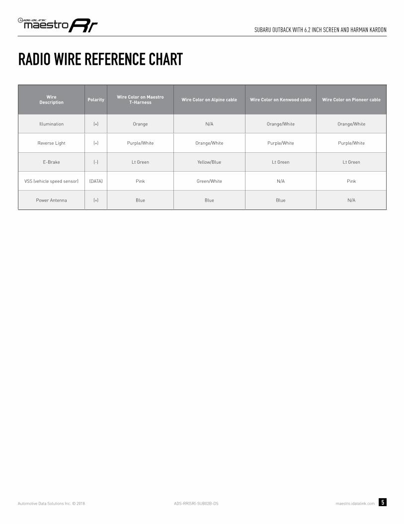
ADS-RR(SR)-SUB02B-DS maestro.idatalink.com
suBaRu outBacK with 6.2 inch scReen and haRman KaRdon
Automotive Data Solutions Inc. © 2018 5
RADIO WIRE REFERENCE CHART
WireDescription Polarity Wire Color on Maestro
T-Harness Wire Color on Alpine cable Wire Color on Kenwood cable Wire Color on Pioneer cable
Illumination (+) Orange N/A Orange/White Orange/White
Reverse Light (+) Purple/White Orange/White Purple/White Purple/White
E-Brake (-) Lt Green Yellow/Blue Lt Green Lt Green
VSS (vehicle speed sensor) (DATA) Pink Green/White N/A Pink
Power Antenna (+) Blue Blue Blue N/A

PROGRAMMED FIRMWAREADS-RR(SR)-SUB02B-DS
PRODUCTS REQUIREDiDatalink Maestro RR Radio Replacement InterfaceiDatalink Maestro SU2 Installation Harness
OPTIONAL ACCESSORIES
ACC-uSU2
Click here for: Radar Integration Installation GuideRadar Integration Owner’s Guide for Kenwood and JVC Radios
E L E C T R O N I C S
INSTALL GUIDESUBARU OUTBACK
WITh 7 INCh SCREEN
2015-2017Retains steeRing wheel contRols, amplifieR and moRe!
NOTICE: Automotive Data Solutions Inc. (ADS) recommends having this installation performed by a certified technician. Logos and trademarks used here in are the properties of their respective owners.

ADS-RR(SR)-SUB02B-DS maestro.idatalink.com
suBaRu outBacK with 7 inch scReen 2015-2017
Automotive Data Solutions Inc. © 2018 2
WELCOME
NEED hELP?
Congratulations on the purchase of your iDatalink Maestro RR Radio replacement solution. You are now a few simple steps away from enjoying your new car radio with enhanced features. Before starting your installation, please ensure that your iDatalink Maestro module is programmed with the correct fi rmware and that you carefully review the Installation Diagram and Vehicle Wire Refer-ence Chart.
Please note that Maestro RR will only retain functionalities that were originally available in the vehicle.
1 866 427-2999
maestro.idatalink.com/supportwww.12voltdata.com/forum
TABLE OF CONTENTS
Installation Instructions 3
Wiring Diagram 4
Radio Wire Reference Chart 5

ADS-RR(SR)-SUB02B-DS maestro.idatalink.com
suBaRu outBacK with 7 inch scReen 2015-2017
Automotive Data Solutions Inc. © 2018 3
INSTALLATION INSTRUCTIONS STEP 1
• Unbox the aftermarket radio and locate its main harness.
• Cut the WHITE, GRAY, GREEN and PURPLE RCA tips.
• Connect the wires from aftermarket radio main harness to the SU2 T-harness and match the wire functions.
• Remove the factory radio.
STEP 2
• Assemble the SU2 T-harness and connect it to the factory radio harness.
STEP 3Note: Connection required if the vehicle is equipped with Starlink telematics and a SOS button.
• Connect the BROWN Starlink wire to PINK or WHITE/BLUE (pin 8) of the 8 pin connector behind the OEM Radio.
STEP 4• Plug the OBDII connector into the OBDII of the vehicle,
under driver dash.
STEP 5• Plug the aftermarket radio harnesses into the aftermarket
radio.
• Plug the AUX cable to the aftermarket radio.
• Plug the RCA cable to the aftermarket radio.
• Plug the Data cable to the data port of the aftermarket radio.
• Insert the Audio cable into the iDatalink 3.5 mm audio jack of the aftermarket radio.
STEP 6• Connect all the harnesses to the Maestro RR module then
test your installation.
TROUBLESHOOTING TIPS:
• To reset the module back its factory settings, turn the key to the OFF position then disconnect all connectors from the module. Press and hold the module’s programming button and connect all the connectors back to the module. Wait, the module’s LED will fl ash RED rapidly (this may take up to 10 seconds). Release the programming button. Wait, the LED will turn solid GREEN for 2 seconds.
• For technical assistance call 1-866-427-2999 or e-mail “[email protected]”. Visit us at “maestro.idatalink.com/support” and “www.12voltdata.com/forum/”
5

ADS-RR(SR)-SUB02B-DS maestro.idatalink.com
suBaRu outBacK with 7 inch scReen 2015-2017
Automotive Data Solutions Inc. © 2018 4
5
BACKUP CAMBACKUP CAMCC
AA
AUXAUX
BB
D
GREENN.C.
MAESTRO RR MODULE
CUT AND REMOVE THE RCA JACKS
STEP 1
MAINHARNESS
SU2 T-HARNESS
WHITE - LF SPEAKER (+)WHITE/BLACK - LF SPEAKER (-)GRAY - RF SPEAKER (+)GRAY/BLACK - RF SPEAKER (-)GREEN - LR SPEAKER (+)GREEN/BLACK - LR SPEAKER (-)
PURPLE/BLACK - RR SPEAKER (-)
YELLOW - 12V (+)
BLACK - GROUNDRED - ACCESSORY (+)
BLUE/WHITE - AMP. TURN ON (+)
PURPLE - RR SPEAKER (+)
STEP 5
STEP 6
ORANGE - ILLUMINATION (+)PURPLE/WHITE - REVERSE LIGHT (+)LTGREEN - E-BRAKE (-)
BLUE - POWER ANTENNA
STARLINK PINK OR WHITE/BLUE - 08
PINK - VEHICLE SPEED
WIRING DIAGRAM
WIRES FROMVEHICLE
FACTORY RADIO HARNESS
8 PIN CONNECTOR BEHIND OEM RADIO
STEP 2
STEP 4
STEP 3
OBDII CONNECTOR
SEE RADIO WIREREFERENCECHARTFOR RADIO WIRECOLORS
DATACABLE
AUDIOCABLE
CONNECT TOAFTERMARKET RADIO
CONNECTIONS NOT REQUIRED
BLUE
NC
NC
YELLOW

ADS-RR(SR)-SUB02B-DS maestro.idatalink.com
suBaRu outBacK with 7 inch scReen 2015-2017
Automotive Data Solutions Inc. © 2018 5
RADIO WIRE REFERENCE CHART
WireDescription Polarity Wire Color on Maestro
T-Harness Wire Color on Alpine cable Wire Color on Kenwood cable Wire Color on Pioneer cable
Illumination (+) Orange N/A Orange/White Orange/White
Reverse Light (+) Purple/White Orange/White Purple/White Purple/White
E-Brake (-) Lt Green Yellow/Blue Lt Green Lt Green
VSS (vehicle speed sensor) (DATA) Pink Green/White N/A Pink
Power Antenna (+) Blue Blue Blue N/A

PROGRAMMED FIRMWAREADS-RR(SR)-SUB02B-DS
PRODUCTS REQUIREDiDatalink Maestro RR Radio Replacement InterfaceiDatalink Maestro SU2 Installation Harness
OPTIONAL ACCESSORIES
ACC-uSU2
Click here for: Radar Integration Installation GuideRadar Integration Owner’s Guide for Kenwood and JVC Radios
E L E C T R O N I C S
INSTALL GUIDESUBARU OUTBACK
WITh 7 INCh SCREEN AND hARMAN KARDON
2015-2017Retains steeRing wheel contRols, amplifieR and moRe!
NOTICE: Automotive Data Solutions Inc. (ADS) recommends having this installation performed by a certified technician. Logos and trademarks used here in are the properties of their respective owners.

ADS-RR(SR)-SUB02B-DS maestro.idatalink.com
suBaRu outBacK with 7 inch scReen and haRman KaRdon
Automotive Data Solutions Inc. © 2018 2
WELCOME
NEED hELP?
Congratulations on the purchase of your iDatalink Maestro RR Radio replacement solution. You are now a few simple steps away from enjoying your new car radio with enhanced features. Before starting your installation, please ensure that your iDatalink Maestro module is programmed with the correct fi rmware and that you carefully review the Installation Diagram and Vehicle Wire Refer-ence Chart.
Please note that Maestro RR will only retain functionalities that were originally available in the vehicle.
1 866 427-2999
maestro.idatalink.com/supportwww.12voltdata.com/forum
TABLE OF CONTENTS
Installation Instructions 3
Wiring Diagram 4
Radio Wire Reference Chart 5

ADS-RR(SR)-SUB02B-DS maestro.idatalink.com
suBaRu outBacK with 7 inch scReen and haRman KaRdon
Automotive Data Solutions Inc. © 2018 3
INSTALLATION INSTRUCTIONS STEP 1
• Unbox the aftermarket radio and locate its main harness.
• Connect the wires from aftermarket radio main harness to the SU2 T-harness and match the wire functions.
• Remove the factory radio.
STEP 2
• Assemble the SU2 T-harness and connect it to the factory radio harness.
STEP 3Note: Connection required if the vehicle is equipped with Starlink telematics and a SOS button.
• Connect the BROWN Starlink wire to PINK or WHITE/BLUE (pin 8) of the 8 pin connector behind the OEM Radio.
STEP 4• Plug the OBDII connector into the OBDII of the vehicle,
under driver dash.
STEP 5• Plug the aftermarket radio harnesses into the aftermarket
radio.
• Plug the AUX cable to the aftermarket radio.
• Plug the RCA cable to the aftermarket radio.
• Plug the Data cable to the data port of the aftermarket radio.
• Insert the Audio cable into the iDatalink 3.5 mm audio jack of the aftermarket radio.
STEP 6• Connect all the harnesses to the Maestro RR module then
test your installation.
TROUBLESHOOTING TIPS:
• To reset the module back its factory settings, turn the key to the OFF position then disconnect all connectors from the module. Press and hold the module’s programming button and connect all the connectors back to the module. Wait, the module’s LED will fl ash RED rapidly (this may take up to 10 seconds). Release the programming button. Wait, the LED will turn solid GREEN for 2 seconds.
• For technical assistance call 1-866-427-2999 or e-mail “[email protected]”. Visit us at “maestro.idatalink.com/support” and “www.12voltdata.com/forum/”
7

ADS-RR(SR)-SUB02B-DS maestro.idatalink.com
suBaRu outBacK with 7 inch scReen and haRman KaRdon
Automotive Data Solutions Inc. © 2018 4
7
BACKUP CAMBACKUP CAMCC
AA
AUXAUX
BB
D
GREENN.C.
MAESTRO RR MODULE
STEP 1
SU2 T-HARNESS
STEP 5
STEP 6STARLINK PINK OR WHITE/BLUE - 08
WIRING DIAGRAM
WIRES FROMVEHICLE
FACTORY RADIO HARNESS
8 PIN CONNECTOR BEHIND OEM RADIO
STEP 2
STEP 4
STEP 3
OBDII CONNECTOR
DATACABLE
AUDIOCABLE
CONNECT TOAFTERMARKET RADIO
CONNECTIONS NOT REQUIRED
BLUE
NC
NC
YELLOW
MAINHARNESS
YELLOW - 12V (+)
BLACK - GROUNDRED - ACCESSORY (+)
BLUE/WHITE - AMP. TURN ON (+)
ORANGE - ILLUMINATION (+)PURPLE/WHITE - REVERSE LIGHT (+)LTGREEN - E-BRAKE (-)
BLUE - POWER ANTENNAPINK - VEHICLE SPEED
SEE RADIO WIREREFERENCECHARTFOR RADIO WIRECOLORS
WHITEWHITE/BLACKGRAYGRAY/BLACKGREENGREEN/BLACK
PURPLE/BLACKPURPLE
LF RCA INPUT
RF RCA INPUT
LR RCA INPUT
RR RCA INPUT

ADS-RR(SR)-SUB02B-DS maestro.idatalink.com
suBaRu outBacK with 7 inch scReen and haRman KaRdon
Automotive Data Solutions Inc. © 2018 5
RADIO WIRE REFERENCE CHART
WireDescription Polarity Wire Color on Maestro
T-Harness Wire Color on Alpine cable Wire Color on Kenwood cable Wire Color on Pioneer cable
Illumination (+) Orange N/A Orange/White Orange/White
Reverse Light (+) Purple/White Orange/White Purple/White Purple/White
E-Brake (-) Lt Green Yellow/Blue Lt Green Lt Green
VSS (vehicle speed sensor) (DATA) Pink Green/White N/A Pink
Power Antenna (+) Blue Blue Blue N/A

PROGRAMMED FIRMWAREADS-RR(SR)-SUB02B-DS
PRODUCTS REQUIREDiDatalink Maestro RR Radio Replacement InterfaceiDatalink Maestro SU2 Installation Harness
OPTIONAL ACCESSORIES
ACC-uSU2
Click here for: Radar Integration Installation GuideRadar Integration Owner’s Guide for Kenwood and JVC Radios
E L E C T R O N I C S
INSTALL GUIDESUBARU WRX STI
WITh 6.2 INCh SCREEN
2016-2018Retains steeRing wheel contRols, amplifieR and moRe!
NOTICE: Automotive Data Solutions Inc. (ADS) recommends having this installation performed by a certified technician. Logos and trademarks used here in are the properties of their respective owners.

ADS-RR(SR)-SUB02B-DS maestro.idatalink.com
suBaRu wRX sti with 6.2 inch scReen 2016-2018
Automotive Data Solutions Inc. © 2018 2
WELCOME
NEED hELP?
Congratulations on the purchase of your iDatalink Maestro RR Radio replacement solution. You are now a few simple steps away from enjoying your new car radio with enhanced features. Before starting your installation, please ensure that your iDatalink Maestro module is programmed with the correct fi rmware and that you carefully review the Installation Diagram and Vehicle Wire Refer-ence Chart.
Please note that Maestro RR will only retain functionalities that were originally available in the vehicle.
1 866 427-2999
maestro.idatalink.com/supportwww.12voltdata.com/forum
TABLE OF CONTENTS
Installation Instructions 3
Wiring Diagram 4
Radio Wire Reference Chart 5

ADS-RR(SR)-SUB02B-DS maestro.idatalink.com
suBaRu wRX sti with 6.2 inch scReen 2016-2018
Automotive Data Solutions Inc. © 2018 3
INSTALLATION INSTRUCTIONS STEP 1
• Unbox the aftermarket radio and locate its main harness.
• Cut the WHITE, GRAY, GREEN and PURPLE RCA tips.
• Connect the wires from aftermarket radio main harness to the SU2 T-harness and match the wire functions.
• Remove the factory radio.
STEP 2
• Assemble the SU2 T-harness and connect it to the factory radio harness.
STEP 3Note: Connection required if the vehicle is equipped with Starlink telematics and a SOS button.
• Connect the BROWN Starlink wire to PINK or WHITE/BLUE (pin 8) of the 8 pin connector behind the OEM Radio.
STEP 4• Plug the OBDII connector into the OBDII of the vehicle,
under driver dash.
STEP 5• Plug the aftermarket radio harnesses into the aftermarket
radio.
• Plug the AUX cable to the aftermarket radio.
• Plug the RCA cable to the aftermarket radio.
• Plug the Data cable to the data port of the aftermarket radio.
• Insert the Audio cable into the iDatalink 3.5 mm audio jack of the aftermarket radio.
STEP 6• Connect all the harnesses to the Maestro RR module then
test your installation.
TROUBLESHOOTING TIPS:
• To reset the module back its factory settings, turn the key to the OFF position then disconnect all connectors from the module. Press and hold the module’s programming button and connect all the connectors back to the module. Wait, the module’s LED will fl ash RED rapidly (this may take up to 10 seconds). Release the programming button. Wait, the LED will turn solid GREEN for 2 seconds.
• For technical assistance call 1-866-427-2999 or e-mail “[email protected]”. Visit us at “maestro.idatalink.com/support” and “www.12voltdata.com/forum/”
4

ADS-RR(SR)-SUB02B-DS maestro.idatalink.com
suBaRu wRX sti with 6.2 inch scReen 2016-2018
Automotive Data Solutions Inc. © 2018 4
4
BACKUP CAMBACKUP CAMCC
AUXAUX
AA
D
BB
MAESTRO RR MODULE
CUT AND REMOVE THE RCA JACKS
STEP 1
MAINHARNESS
SU2 T-HARNESS
WHITE - LF SPEAKER (+)WHITE/BLACK - LF SPEAKER (-)GRAY - RF SPEAKER (+)GRAY/BLACK - RF SPEAKER (-)GREEN - LR SPEAKER (+)GREEN/BLACK - LR SPEAKER (-)
PURPLE/BLACK - RR SPEAKER (-)
YELLOW - 12V (+)
BLACK - GROUNDRED - ACCESSORY (+)
BLUE/WHITE - AMP. TURN ON (+)
PURPLE - RR SPEAKER (+)
STEP 5
STEP 6
ORANGE - ILLUMINATION (+)PURPLE/WHITE - REVERSE LIGHT (+)LTGREEN - E-BRAKE (-)
BLUE - POWER ANTENNAPINK - VEHICLE SPEED
WIRING DIAGRAM
WIRES FROMVEHICLE
FACTORY RADIO HARNESSSTEP 2
STEP 4 OBDII CONNECTOR
SEE RADIO WIREREFERENCECHARTFOR RADIO WIRECOLORS
DATACABLE
AUDIOCABLE
CONNECT TOAFTERMARKET RADIO
BLUE
GREENN.C.
CONNECTIONS NOT REQUIRED
YELLOW
STARLINK PINK OR WHITE/BLUE - 08
8 PIN CONNECTOR BEHIND OEM RADIOSTEP 3

ADS-RR(SR)-SUB02B-DS maestro.idatalink.com
suBaRu wRX sti with 6.2 inch scReen 2016-2018
Automotive Data Solutions Inc. © 2018 5
RADIO WIRE REFERENCE CHART
WireDescription Polarity Wire Color on Maestro
T-Harness Wire Color on Alpine cable Wire Color on Kenwood cable Wire Color on Pioneer cable
Illumination (+) Orange N/A Orange/White Orange/White
Reverse Light (+) Purple/White Orange/White Purple/White Purple/White
E-Brake (-) Lt Green Yellow/Blue Lt Green Lt Green
VSS (vehicle speed sensor) (DATA) Pink Green/White N/A Pink
Power Antenna (+) Blue Blue Blue N/A

PROGRAMMED FIRMWAREADS-RR(SR)-SUB02B-DS
PRODUCTS REQUIREDiDatalink Maestro RR Radio Replacement InterfaceiDatalink Maestro SU2 Installation Harness
OPTIONAL ACCESSORIES
ACC-uSU2
Click here for: Radar Integration Installation GuideRadar Integration Owner’s Guide for Kenwood and JVC Radios
E L E C T R O N I C S
INSTALL GUIDESUBARU WRX STI
WITh 6.2 INCh SCREEN AND hARMAN KARDON
2016-2018Retains steeRing wheel contRols, amplifieR and moRe!
NOTICE: Automotive Data Solutions Inc. (ADS) recommends having this installation performed by a certified technician. Logos and trademarks used here in are the properties of their respective owners.

ADS-RR(SR)-SUB02B-DS maestro.idatalink.com
suBaRu wRX sti with 6.2 inch scReen and haRman KaRdon
Automotive Data Solutions Inc. © 2018 2
WELCOME
NEED hELP?
Congratulations on the purchase of your iDatalink Maestro RR Radio replacement solution. You are now a few simple steps away from enjoying your new car radio with enhanced features. Before starting your installation, please ensure that your iDatalink Maestro module is programmed with the correct fi rmware and that you carefully review the Installation Diagram and Vehicle Wire Refer-ence Chart.
Please note that Maestro RR will only retain functionalities that were originally available in the vehicle.
1 866 427-2999
maestro.idatalink.com/supportwww.12voltdata.com/forum
TABLE OF CONTENTS
Installation Instructions 3
Wiring Diagram 4
Radio Wire Reference Chart 5

ADS-RR(SR)-SUB02B-DS maestro.idatalink.com
suBaRu wRX sti with 6.2 inch scReen and haRman KaRdon
Automotive Data Solutions Inc. © 2018 3
INSTALLATION INSTRUCTIONS STEP 1
• Unbox the aftermarket radio and locate its main harness.
• Connect the wires from aftermarket radio main harness to the SU2 T-harness and match the wire functions.
• Remove the factory radio.
STEP 2
• Assemble the SU2 T-harness and connect it to the factory radio harness.
STEP 3Note: Connection required if the vehicle is equipped with Starlink telematics and a SOS button.
• Connect the BROWN Starlink wire to PINK or WHITE/BLUE (pin 8) of the 8 pin connector behind the OEM Radio.
STEP 4• Plug the OBDII connector into the OBDII of the vehicle,
under driver dash.
STEP 5• Plug the aftermarket radio harnesses into the aftermarket
radio.
• Plug the AUX cable to the aftermarket radio.
• Plug the RCA cable to the aftermarket radio.
• Plug the Data cable to the data port of the aftermarket radio.
• Insert the Audio cable into the iDatalink 3.5 mm audio jack of the aftermarket radio.
STEP 6• Connect all the harnesses to the Maestro RR module then
test your installation.
TROUBLESHOOTING TIPS:
• To reset the module back its factory settings, turn the key to the OFF position then disconnect all connectors from the module. Press and hold the module’s programming button and connect all the connectors back to the module. Wait, the module’s LED will fl ash RED rapidly (this may take up to 10 seconds). Release the programming button. Wait, the LED will turn solid GREEN for 2 seconds.
• For technical assistance call 1-866-427-2999 or e-mail “[email protected]”. Visit us at “maestro.idatalink.com/support” and “www.12voltdata.com/forum/”
6

ADS-RR(SR)-SUB02B-DS maestro.idatalink.com
suBaRu wRX sti with 6.2 inch scReen and haRman KaRdon
Automotive Data Solutions Inc. © 2018 4
6
BACKUP CAMBACKUP CAMCC
AUXAUX
AA
D
BB
STARLINK PINK OR WHITE/BLUE - 08
8 PIN CONNECTOR BEHIND OEM RADIOSTEP 3
MAESTRO RR MODULE
STEP 1
SU2 T-HARNESS
STEP 5
STEP 6
WIRING DIAGRAM
WIRES FROMVEHICLE
FACTORY RADIO HARNESSSTEP 2
STEP 4 OBDII CONNECTOR
DATACABLE
AUDIOCABLE
CONNECT TOAFTERMARKET RADIO
BLUE
CONNECTIONS NOT REQUIRED
YELLOW
MAINHARNESS
YELLOW - 12V (+)
BLACK - GROUNDRED - ACCESSORY (+)
BLUE/WHITE - AMP. TURN ON (+)
ORANGE - ILLUMINATION (+)PURPLE/WHITE - REVERSE LIGHT (+)LTGREEN - E-BRAKE (-)
BLUE - POWER ANTENNAPINK - VEHICLE SPEED
SEE RADIO WIREREFERENCECHARTFOR RADIO WIRECOLORS
WHITEWHITE/BLACKGRAYGRAY/BLACKGREENGREEN/BLACK
PURPLE/BLACKPURPLE
LF RCA INPUT
RF RCA INPUT
LR RCA INPUT
RR RCA INPUT
RCA CABLES
GREENN.C.

ADS-RR(SR)-SUB02B-DS maestro.idatalink.com
suBaRu wRX sti with 6.2 inch scReen and haRman KaRdon
Automotive Data Solutions Inc. © 2018 5
RADIO WIRE REFERENCE CHART
WireDescription Polarity Wire Color on Maestro
T-Harness Wire Color on Alpine cable Wire Color on Kenwood cable Wire Color on Pioneer cable
Illumination (+) Orange N/A Orange/White Orange/White
Reverse Light (+) Purple/White Orange/White Purple/White Purple/White
E-Brake (-) Lt Green Yellow/Blue Lt Green Lt Green
VSS (vehicle speed sensor) (DATA) Pink Green/White N/A Pink
Power Antenna (+) Blue Blue Blue N/A

PROGRAMMED FIRMWAREADS-RR(SR)-SUB02B-DS
PRODUCTS REQUIREDiDatalink Maestro RR Radio Replacement InterfaceiDatalink Maestro SU2 Installation Harness
OPTIONAL ACCESSORIES
ACC-uSU2
Click here for: Radar Integration Installation GuideRadar Integration Owner’s Guide for Kenwood and JVC Radios
E L E C T R O N I C S
INSTALL GUIDESUBARU WRX STI
WITh 7 INCh SCREEN
2016-2018Retains steeRing wheel contRols, amplifieR and moRe!
NOTICE: Automotive Data Solutions Inc. (ADS) recommends having this installation performed by a certified technician. Logos and trademarks used here in are the properties of their respective owners.

ADS-RR(SR)-SUB02B-DS maestro.idatalink.com
suBaRu wRX sti with 7 inch scReen 2016-2018
Automotive Data Solutions Inc. © 2018 2
WELCOME
NEED hELP?
Congratulations on the purchase of your iDatalink Maestro RR Radio replacement solution. You are now a few simple steps away from enjoying your new car radio with enhanced features. Before starting your installation, please ensure that your iDatalink Maestro module is programmed with the correct fi rmware and that you carefully review the Installation Diagram and Vehicle Wire Refer-ence Chart.
Please note that Maestro RR will only retain functionalities that were originally available in the vehicle.
1 866 427-2999
maestro.idatalink.com/supportwww.12voltdata.com/forum
TABLE OF CONTENTS
Installation Instructions 3
Wiring Diagram 4
Radio Wire Reference Chart 5

ADS-RR(SR)-SUB02B-DS maestro.idatalink.com
suBaRu wRX sti with 7 inch scReen 2016-2018
Automotive Data Solutions Inc. © 2018 3
INSTALLATION INSTRUCTIONS STEP 1
• Unbox the aftermarket radio and locate its main harness.
• Cut the WHITE, GRAY, GREEN and PURPLE RCA tips.
• Connect the wires from aftermarket radio main harness to the SU2 T-harness and match the wire functions.
• Remove the factory radio.
STEP 2
• Assemble the SU2 T-harness and connect it to the factory radio harness.
STEP 3Note: Connection required if the vehicle is equipped with Starlink telematics and a SOS button.
• Connect the BROWN Starlink wire to PINK or WHITE/BLUE (pin 8) of the 8 pin connector behind the OEM Radio.
STEP 4• Plug the OBDII connector into the OBDII of the vehicle,
under driver dash.
STEP 5• Plug the aftermarket radio harnesses into the aftermarket
radio.
• Plug the AUX cable to the aftermarket radio.
• Plug the RCA cable to the aftermarket radio.
• Plug the Data cable to the data port of the aftermarket radio.
• Insert the Audio cable into the iDatalink 3.5 mm audio jack of the aftermarket radio.
STEP 6• Connect all the harnesses to the Maestro RR module then
test your installation.
TROUBLESHOOTING TIPS:
• To reset the module back its factory settings, turn the key to the OFF position then disconnect all connectors from the module. Press and hold the module’s programming button and connect all the connectors back to the module. Wait, the module’s LED will fl ash RED rapidly (this may take up to 10 seconds). Release the programming button. Wait, the LED will turn solid GREEN for 2 seconds.
• For technical assistance call 1-866-427-2999 or e-mail “[email protected]”. Visit us at “maestro.idatalink.com/support” and “www.12voltdata.com/forum/”
5

ADS-RR(SR)-SUB02B-DS maestro.idatalink.com
suBaRu wRX sti with 7 inch scReen 2016-2018
Automotive Data Solutions Inc. © 2018 4
5
BACKUP CAMBACKUP CAMCC
AA
AUXAUX
BB
D
GREENN.C.
MAESTRO RR MODULE
CUT AND REMOVE THE RCA JACKS
STEP 1
MAINHARNESS
SU2 T-HARNESS
WHITE - LF SPEAKER (+)WHITE/BLACK - LF SPEAKER (-)GRAY - RF SPEAKER (+)GRAY/BLACK - RF SPEAKER (-)GREEN - LR SPEAKER (+)GREEN/BLACK - LR SPEAKER (-)
PURPLE/BLACK - RR SPEAKER (-)
YELLOW - 12V (+)
BLACK - GROUNDRED - ACCESSORY (+)
BLUE/WHITE - AMP. TURN ON (+)
PURPLE - RR SPEAKER (+)
STEP 5
STEP 6
ORANGE - ILLUMINATION (+)PURPLE/WHITE - REVERSE LIGHT (+)LTGREEN - E-BRAKE (-)
BLUE - POWER ANTENNA
STARLINK PINK OR WHITE/BLUE - 08
PINK - VEHICLE SPEED
WIRING DIAGRAM
WIRES FROMVEHICLE
FACTORY RADIO HARNESS
8 PIN CONNECTOR BEHIND OEM RADIO
STEP 2
STEP 4
STEP 3
OBDII CONNECTOR
SEE RADIO WIREREFERENCECHARTFOR RADIO WIRECOLORS
DATACABLE
AUDIOCABLE
CONNECT TOAFTERMARKET RADIO
CONNECTIONS NOT REQUIRED
BLUE
NC
NC
YELLOW

ADS-RR(SR)-SUB02B-DS maestro.idatalink.com
suBaRu wRX sti with 7 inch scReen 2016-2018
Automotive Data Solutions Inc. © 2018 5
RADIO WIRE REFERENCE CHART
WireDescription Polarity Wire Color on Maestro
T-Harness Wire Color on Alpine cable Wire Color on Kenwood cable Wire Color on Pioneer cable
Illumination (+) Orange N/A Orange/White Orange/White
Reverse Light (+) Purple/White Orange/White Purple/White Purple/White
E-Brake (-) Lt Green Yellow/Blue Lt Green Lt Green
VSS (vehicle speed sensor) (DATA) Pink Green/White N/A Pink
Power Antenna (+) Blue Blue Blue N/A

PROGRAMMED FIRMWAREADS-RR(SR)-SUB02B-DS
PRODUCTS REQUIREDiDatalink Maestro RR Radio Replacement InterfaceiDatalink Maestro SU2 Installation Harness
OPTIONAL ACCESSORIES
ACC-uSU2
Click here for: Radar Integration Installation GuideRadar Integration Owner’s Guide for Kenwood and JVC Radios
E L E C T R O N I C S
INSTALL GUIDESUBARU WRX STI
WITh 7 INCh SCREEN AND hARMAN KARDON
2016-2018Retains steeRing wheel contRols, amplifieR and moRe!
NOTICE: Automotive Data Solutions Inc. (ADS) recommends having this installation performed by a certified technician. Logos and trademarks used here in are the properties of their respective owners.

ADS-RR(SR)-SUB02B-DS maestro.idatalink.com
suBaRu wRX sti with 7 inch scReen and haRman KaRdon
Automotive Data Solutions Inc. © 2018 2
WELCOME
NEED hELP?
Congratulations on the purchase of your iDatalink Maestro RR Radio replacement solution. You are now a few simple steps away from enjoying your new car radio with enhanced features. Before starting your installation, please ensure that your iDatalink Maestro module is programmed with the correct fi rmware and that you carefully review the Installation Diagram and Vehicle Wire Refer-ence Chart.
Please note that Maestro RR will only retain functionalities that were originally available in the vehicle.
1 866 427-2999
maestro.idatalink.com/supportwww.12voltdata.com/forum
TABLE OF CONTENTS
Installation Instructions 3
Wiring Diagram 4
Radio Wire Reference Chart 5

ADS-RR(SR)-SUB02B-DS maestro.idatalink.com
suBaRu wRX sti with 7 inch scReen and haRman KaRdon
Automotive Data Solutions Inc. © 2018 3
INSTALLATION INSTRUCTIONS STEP 1
• Unbox the aftermarket radio and locate its main harness.
• Connect the wires from aftermarket radio main harness to the SU2 T-harness and match the wire functions.
• Remove the factory radio.
STEP 2
• Assemble the SU2 T-harness and connect it to the factory radio harness.
STEP 3Note: Connection required if the vehicle is equipped with Starlink telematics and a SOS button.
• Connect the BROWN Starlink wire to PINK or WHITE/BLUE (pin 8) of the 8 pin connector behind the OEM Radio.
STEP 4• Plug the OBDII connector into the OBDII of the vehicle,
under driver dash.
STEP 5• Plug the aftermarket radio harnesses into the aftermarket
radio.
• Plug the AUX cable to the aftermarket radio.
• Plug the RCA cable to the aftermarket radio.
• Plug the Data cable to the data port of the aftermarket radio.
• Insert the Audio cable into the iDatalink 3.5 mm audio jack of the aftermarket radio.
STEP 6• Connect all the harnesses to the Maestro RR module then
test your installation.
TROUBLESHOOTING TIPS:
• To reset the module back its factory settings, turn the key to the OFF position then disconnect all connectors from the module. Press and hold the module’s programming button and connect all the connectors back to the module. Wait, the module’s LED will fl ash RED rapidly (this may take up to 10 seconds). Release the programming button. Wait, the LED will turn solid GREEN for 2 seconds.
• For technical assistance call 1-866-427-2999 or e-mail “[email protected]”. Visit us at “maestro.idatalink.com/support” and “www.12voltdata.com/forum/”
7

ADS-RR(SR)-SUB02B-DS maestro.idatalink.com
suBaRu wRX sti with 7 inch scReen and haRman KaRdon
Automotive Data Solutions Inc. © 2018 4
7
BACKUP CAMBACKUP CAMCC
AA
AUXAUX
BB
D
GREENN.C.
MAESTRO RR MODULE
STEP 1
SU2 T-HARNESS
STEP 5
STEP 6STARLINK PINK OR WHITE/BLUE - 08
WIRING DIAGRAM
WIRES FROMVEHICLE
FACTORY RADIO HARNESS
8 PIN CONNECTOR BEHIND OEM RADIO
STEP 2
STEP 4
STEP 3
OBDII CONNECTOR
DATACABLE
AUDIOCABLE
CONNECT TOAFTERMARKET RADIO
CONNECTIONS NOT REQUIRED
BLUE
NC
NC
YELLOW
MAINHARNESS
YELLOW - 12V (+)
BLACK - GROUNDRED - ACCESSORY (+)
BLUE/WHITE - AMP. TURN ON (+)
ORANGE - ILLUMINATION (+)PURPLE/WHITE - REVERSE LIGHT (+)LTGREEN - E-BRAKE (-)
BLUE - POWER ANTENNAPINK - VEHICLE SPEED
SEE RADIO WIREREFERENCECHARTFOR RADIO WIRECOLORS
WHITEWHITE/BLACKGRAYGRAY/BLACKGREENGREEN/BLACK
PURPLE/BLACKPURPLE
LF RCA INPUT
RF RCA INPUT
LR RCA INPUT
RR RCA INPUT

ADS-RR(SR)-SUB02B-DS maestro.idatalink.com
suBaRu wRX sti with 7 inch scReen and haRman KaRdon
Automotive Data Solutions Inc. © 2018 5
RADIO WIRE REFERENCE CHART
WireDescription Polarity Wire Color on Maestro
T-Harness Wire Color on Alpine cable Wire Color on Kenwood cable Wire Color on Pioneer cable
Illumination (+) Orange N/A Orange/White Orange/White
Reverse Light (+) Purple/White Orange/White Purple/White Purple/White
E-Brake (-) Lt Green Yellow/Blue Lt Green Lt Green
VSS (vehicle speed sensor) (DATA) Pink Green/White N/A Pink
Power Antenna (+) Blue Blue Blue N/A

PROGRAMMED FIRMWAREADS-RR(SR)-SUB02B-DS
PRODUCTS REQUIREDiDatalink Maestro RR Radio Replacement InterfaceiDatalink Maestro SU2 Installation Harness
OPTIONAL ACCESSORIES
ACC-uSU2
Click here for: Radar Integration Installation GuideRadar Integration Owner’s Guide for Kenwood and JVC Radios
E L E C T R O N I C S
INSTALL GUIDESUBARU WRX STI
WITh NAV
2015Retains steeRing wheel contRols, amplifieR and moRe!
NOTICE: Automotive Data Solutions Inc. (ADS) recommends having this installation performed by a certified technician. Logos and trademarks used here in are the properties of their respective owners.

ADS-RR(SR)-SUB02B-DS maestro.idatalink.com
suBaRu wRX sti with naV 2015
Automotive Data Solutions Inc. © 2018 2
WELCOME
NEED hELP?
Congratulations on the purchase of your iDatalink Maestro RR Radio replacement solution. You are now a few simple steps away from enjoying your new car radio with enhanced features. Before starting your installation, please ensure that your iDatalink Maestro module is programmed with the correct fi rmware and that you carefully review the Installation Diagram and Vehicle Wire Refer-ence Chart.
Please note that Maestro RR will only retain functionalities that were originally available in the vehicle.
1 866 427-2999
maestro.idatalink.com/supportwww.12voltdata.com/forum
TABLE OF CONTENTS
Installation Instructions 3
Wiring Diagram 4
Radio Wire Reference Chart 5

ADS-RR(SR)-SUB02B-DS maestro.idatalink.com
suBaRu wRX sti with naV 2015
Automotive Data Solutions Inc. © 2018 3
INSTALLATION INSTRUCTIONS STEP 1
• Unbox the aftermarket radio and locate its main harness.
• Cut the WHITE, GRAY, GREEN and PURPLE RCA tips.
• Connect the wires from aftermarket radio main harness to the SU2 T-harness and match the wire functions.
• Remove the factory radio.
STEP 2
• Assemble the SU2 T-harness and connect it to the factory radio harness.
STEP 3Note: Connection required if the vehicle is equipped with Starlink telematics and a SOS button.
• Connect the BROWN Starlink wire to PINK or WHITE/BLUE (pin 8) of the 8 pin connector behind the OEM Radio.
STEP 4• Plug the OBDII connector into the OBDII of the vehicle,
under driver dash.
STEP 5• Plug the aftermarket radio harnesses into the aftermarket
radio.
• Plug the AUX cable to the aftermarket radio.
• Plug the RCA cable to the aftermarket radio.
• Plug the Data cable to the data port of the aftermarket radio.
• Insert the Audio cable into the iDatalink 3.5 mm audio jack of the aftermarket radio.
STEP 6• Connect all the harnesses to the Maestro RR module then
test your installation.
TROUBLESHOOTING TIPS:
• To reset the module back its factory settings, turn the key to the OFF position then disconnect all connectors from the module. Press and hold the module’s programming button and connect all the connectors back to the module. Wait, the module’s LED will fl ash RED rapidly (this may take up to 10 seconds). Release the programming button. Wait, the LED will turn solid GREEN for 2 seconds.
• For technical assistance call 1-866-427-2999 or e-mail “[email protected]”. Visit us at “maestro.idatalink.com/support” and “www.12voltdata.com/forum/”
5
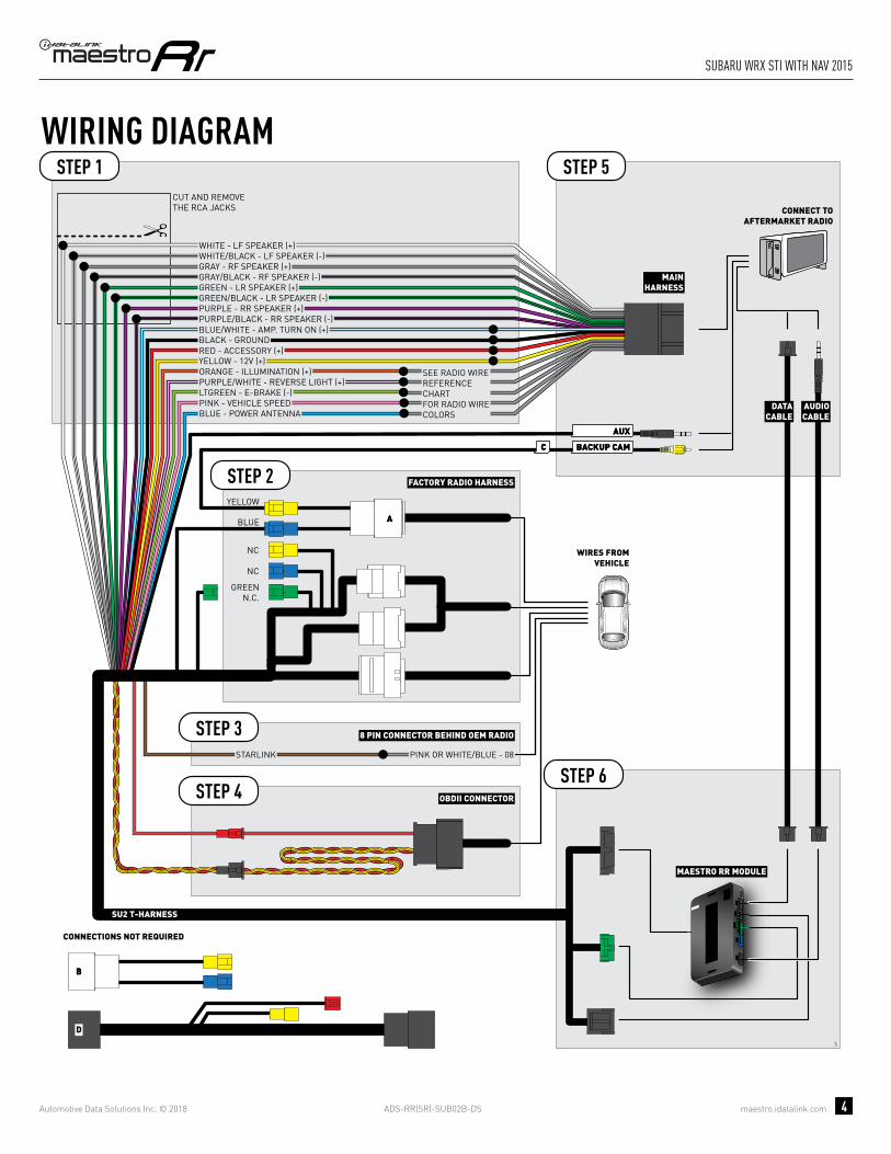
ADS-RR(SR)-SUB02B-DS maestro.idatalink.com
suBaRu wRX sti with naV 2015
Automotive Data Solutions Inc. © 2018 4
5
BACKUP CAMBACKUP CAMCC
AA
AUXAUX
BB
D
GREENN.C.
MAESTRO RR MODULE
CUT AND REMOVE THE RCA JACKS
STEP 1
MAINHARNESS
SU2 T-HARNESS
WHITE - LF SPEAKER (+)WHITE/BLACK - LF SPEAKER (-)GRAY - RF SPEAKER (+)GRAY/BLACK - RF SPEAKER (-)GREEN - LR SPEAKER (+)GREEN/BLACK - LR SPEAKER (-)
PURPLE/BLACK - RR SPEAKER (-)
YELLOW - 12V (+)
BLACK - GROUNDRED - ACCESSORY (+)
BLUE/WHITE - AMP. TURN ON (+)
PURPLE - RR SPEAKER (+)
STEP 5
STEP 6
ORANGE - ILLUMINATION (+)PURPLE/WHITE - REVERSE LIGHT (+)LTGREEN - E-BRAKE (-)
BLUE - POWER ANTENNA
STARLINK PINK OR WHITE/BLUE - 08
PINK - VEHICLE SPEED
WIRING DIAGRAM
WIRES FROMVEHICLE
FACTORY RADIO HARNESS
8 PIN CONNECTOR BEHIND OEM RADIO
STEP 2
STEP 4
STEP 3
OBDII CONNECTOR
SEE RADIO WIREREFERENCECHARTFOR RADIO WIRECOLORS
DATACABLE
AUDIOCABLE
CONNECT TOAFTERMARKET RADIO
CONNECTIONS NOT REQUIRED
BLUE
NC
NC
YELLOW

ADS-RR(SR)-SUB02B-DS maestro.idatalink.com
suBaRu wRX sti with naV 2015
Automotive Data Solutions Inc. © 2018 5
RADIO WIRE REFERENCE CHART
WireDescription Polarity Wire Color on Maestro
T-Harness Wire Color on Alpine cable Wire Color on Kenwood cable Wire Color on Pioneer cable
Illumination (+) Orange N/A Orange/White Orange/White
Reverse Light (+) Purple/White Orange/White Purple/White Purple/White
E-Brake (-) Lt Green Yellow/Blue Lt Green Lt Green
VSS (vehicle speed sensor) (DATA) Pink Green/White N/A Pink
Power Antenna (+) Blue Blue Blue N/A

PROGRAMMED FIRMWAREADS-RR(SR)-SUB02B-DS
PRODUCTS REQUIREDiDatalink Maestro RR Radio Replacement InterfaceiDatalink Maestro SU2 Installation Harness
OPTIONAL ACCESSORIES
ACC-uSU2
Click here for: Radar Integration Installation GuideRadar Integration Owner’s Guide for Kenwood and JVC Radios
E L E C T R O N I C S
INSTALL GUIDESUBARU WRX STI
WITh NAV AND AMP
2015Retains steeRing wheel contRols, amplifieR and moRe!
NOTICE: Automotive Data Solutions Inc. (ADS) recommends having this installation performed by a certified technician. Logos and trademarks used here in are the properties of their respective owners.

ADS-RR(SR)-SUB02B-DS maestro.idatalink.com
suBaRu wRX sti with naV and amp 2015
Automotive Data Solutions Inc. © 2018 2
WELCOME
NEED hELP?
Congratulations on the purchase of your iDatalink Maestro RR Radio replacement solution. You are now a few simple steps away from enjoying your new car radio with enhanced features. Before starting your installation, please ensure that your iDatalink Maestro module is programmed with the correct fi rmware and that you carefully review the Installation Diagram and Vehicle Wire Refer-ence Chart.
Please note that Maestro RR will only retain functionalities that were originally available in the vehicle.
1 866 427-2999
maestro.idatalink.com/supportwww.12voltdata.com/forum
TABLE OF CONTENTS
Installation Instructions 3
Wiring Diagram 4
Radio Wire Reference Chart 5

ADS-RR(SR)-SUB02B-DS maestro.idatalink.com
suBaRu wRX sti with naV and amp 2015
Automotive Data Solutions Inc. © 2018 3
INSTALLATION INSTRUCTIONS STEP 1
• Unbox the aftermarket radio and locate its main harness.
• Connect the wires from aftermarket radio main harness to the SU2 T-harness and match the wire functions.
• Remove the factory radio.
STEP 2
• Assemble the SU2 T-harness and connect it to the factory radio harness.
STEP 3Note: Connection required if the vehicle is equipped with Starlink telematics and a SOS button.
• Connect the BROWN Starlink wire to PINK or WHITE/BLUE (pin 8) of the 8 pin connector behind the OEM Radio.
STEP 4• Plug the OBDII connector into the OBDII of the vehicle,
under driver dash.
STEP 5• Plug the aftermarket radio harnesses into the aftermarket
radio.
• Plug the AUX cable to the aftermarket radio.
• Plug the RCA cable to the aftermarket radio.
• Plug the Data cable to the data port of the aftermarket radio.
• Insert the Audio cable into the iDatalink 3.5 mm audio jack of the aftermarket radio.
STEP 6• Connect all the harnesses to the Maestro RR module then
test your installation.
TROUBLESHOOTING TIPS:
• To reset the module back its factory settings, turn the key to the OFF position then disconnect all connectors from the module. Press and hold the module’s programming button and connect all the connectors back to the module. Wait, the module’s LED will fl ash RED rapidly (this may take up to 10 seconds). Release the programming button. Wait, the LED will turn solid GREEN for 2 seconds.
• For technical assistance call 1-866-427-2999 or e-mail “[email protected]”. Visit us at “maestro.idatalink.com/support” and “www.12voltdata.com/forum/”
7

ADS-RR(SR)-SUB02B-DS maestro.idatalink.com
suBaRu wRX sti with naV and amp 2015
Automotive Data Solutions Inc. © 2018 4
7
BACKUP CAMBACKUP CAMCC
AA
AUXAUX
BB
D
GREENN.C.
MAESTRO RR MODULE
STEP 1
SU2 T-HARNESS
STEP 5
STEP 6STARLINK PINK OR WHITE/BLUE - 08
WIRING DIAGRAM
WIRES FROMVEHICLE
FACTORY RADIO HARNESS
8 PIN CONNECTOR BEHIND OEM RADIO
STEP 2
STEP 4
STEP 3
OBDII CONNECTOR
DATACABLE
AUDIOCABLE
CONNECT TOAFTERMARKET RADIO
CONNECTIONS NOT REQUIRED
BLUE
NC
NC
YELLOW
MAINHARNESS
YELLOW - 12V (+)
BLACK - GROUNDRED - ACCESSORY (+)
BLUE/WHITE - AMP. TURN ON (+)
ORANGE - ILLUMINATION (+)PURPLE/WHITE - REVERSE LIGHT (+)LTGREEN - E-BRAKE (-)
BLUE - POWER ANTENNAPINK - VEHICLE SPEED
SEE RADIO WIREREFERENCECHARTFOR RADIO WIRECOLORS
WHITEWHITE/BLACKGRAYGRAY/BLACKGREENGREEN/BLACK
PURPLE/BLACKPURPLE
LF RCA INPUT
RF RCA INPUT
LR RCA INPUT
RR RCA INPUT

ADS-RR(SR)-SUB02B-DS maestro.idatalink.com
suBaRu wRX sti with naV and amp 2015
Automotive Data Solutions Inc. © 2018 5
RADIO WIRE REFERENCE CHART
WireDescription Polarity Wire Color on Maestro
T-Harness Wire Color on Alpine cable Wire Color on Kenwood cable Wire Color on Pioneer cable
Illumination (+) Orange N/A Orange/White Orange/White
Reverse Light (+) Purple/White Orange/White Purple/White Purple/White
E-Brake (-) Lt Green Yellow/Blue Lt Green Lt Green
VSS (vehicle speed sensor) (DATA) Pink Green/White N/A Pink
Power Antenna (+) Blue Blue Blue N/A

PROGRAMMED FIRMWAREADS-RR(SR)-SUB02B-DS
PRODUCTS REQUIREDiDatalink Maestro RR Radio Replacement InterfaceiDatalink Maestro SU2 Installation Harness
OPTIONAL ACCESSORIES
ACC-uSU2
Click here for: Radar Integration Installation GuideRadar Integration Owner’s Guide for Kenwood and JVC Radios
E L E C T R O N I C S
INSTALL GUIDESUBARU WRX
WITh 6.2 INCh SCREEN
2016-2018Retains steeRing wheel contRols, amplifieR and moRe!
NOTICE: Automotive Data Solutions Inc. (ADS) recommends having this installation performed by a certified technician. Logos and trademarks used here in are the properties of their respective owners.

ADS-RR(SR)-SUB02B-DS maestro.idatalink.com
suBaRu wRX with 6.2 inch scReen 2016-2018
Automotive Data Solutions Inc. © 2018 2
WELCOME
NEED hELP?
Congratulations on the purchase of your iDatalink Maestro RR Radio replacement solution. You are now a few simple steps away from enjoying your new car radio with enhanced features. Before starting your installation, please ensure that your iDatalink Maestro module is programmed with the correct fi rmware and that you carefully review the Installation Diagram and Vehicle Wire Refer-ence Chart.
Please note that Maestro RR will only retain functionalities that were originally available in the vehicle.
1 866 427-2999
maestro.idatalink.com/supportwww.12voltdata.com/forum
TABLE OF CONTENTS
Installation Instructions 3
Wiring Diagram 4
Radio Wire Reference Chart 5
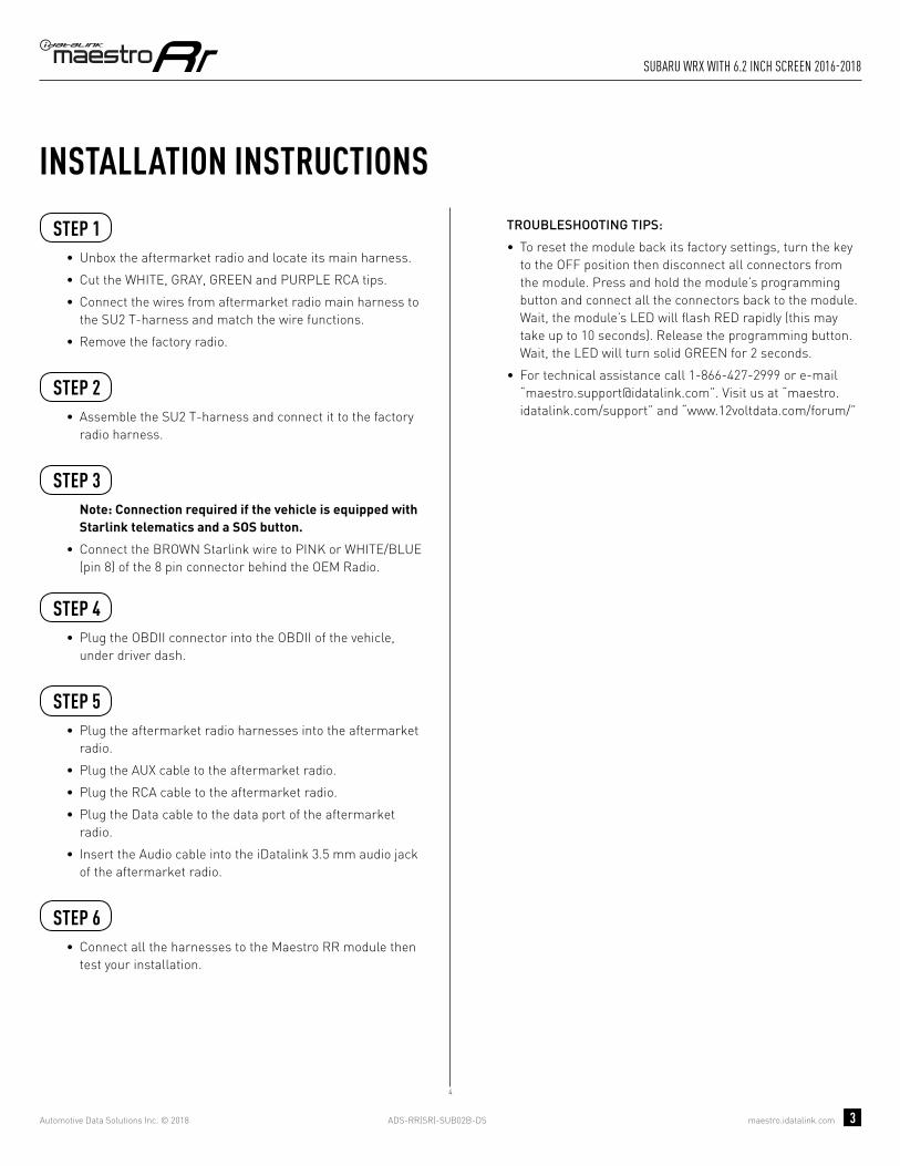
ADS-RR(SR)-SUB02B-DS maestro.idatalink.com
suBaRu wRX with 6.2 inch scReen 2016-2018
Automotive Data Solutions Inc. © 2018 3
INSTALLATION INSTRUCTIONS STEP 1
• Unbox the aftermarket radio and locate its main harness.
• Cut the WHITE, GRAY, GREEN and PURPLE RCA tips.
• Connect the wires from aftermarket radio main harness to the SU2 T-harness and match the wire functions.
• Remove the factory radio.
STEP 2
• Assemble the SU2 T-harness and connect it to the factory radio harness.
STEP 3Note: Connection required if the vehicle is equipped with Starlink telematics and a SOS button.
• Connect the BROWN Starlink wire to PINK or WHITE/BLUE (pin 8) of the 8 pin connector behind the OEM Radio.
STEP 4• Plug the OBDII connector into the OBDII of the vehicle,
under driver dash.
STEP 5• Plug the aftermarket radio harnesses into the aftermarket
radio.
• Plug the AUX cable to the aftermarket radio.
• Plug the RCA cable to the aftermarket radio.
• Plug the Data cable to the data port of the aftermarket radio.
• Insert the Audio cable into the iDatalink 3.5 mm audio jack of the aftermarket radio.
STEP 6• Connect all the harnesses to the Maestro RR module then
test your installation.
TROUBLESHOOTING TIPS:
• To reset the module back its factory settings, turn the key to the OFF position then disconnect all connectors from the module. Press and hold the module’s programming button and connect all the connectors back to the module. Wait, the module’s LED will fl ash RED rapidly (this may take up to 10 seconds). Release the programming button. Wait, the LED will turn solid GREEN for 2 seconds.
• For technical assistance call 1-866-427-2999 or e-mail “[email protected]”. Visit us at “maestro.idatalink.com/support” and “www.12voltdata.com/forum/”
4

ADS-RR(SR)-SUB02B-DS maestro.idatalink.com
suBaRu wRX with 6.2 inch scReen 2016-2018
Automotive Data Solutions Inc. © 2018 4
4
BACKUP CAMBACKUP CAMCC
AUXAUX
AA
D
BB
MAESTRO RR MODULE
CUT AND REMOVE THE RCA JACKS
STEP 1
MAINHARNESS
SU2 T-HARNESS
WHITE - LF SPEAKER (+)WHITE/BLACK - LF SPEAKER (-)GRAY - RF SPEAKER (+)GRAY/BLACK - RF SPEAKER (-)GREEN - LR SPEAKER (+)GREEN/BLACK - LR SPEAKER (-)
PURPLE/BLACK - RR SPEAKER (-)
YELLOW - 12V (+)
BLACK - GROUNDRED - ACCESSORY (+)
BLUE/WHITE - AMP. TURN ON (+)
PURPLE - RR SPEAKER (+)
STEP 5
STEP 6
ORANGE - ILLUMINATION (+)PURPLE/WHITE - REVERSE LIGHT (+)LTGREEN - E-BRAKE (-)
BLUE - POWER ANTENNAPINK - VEHICLE SPEED
WIRING DIAGRAM
WIRES FROMVEHICLE
FACTORY RADIO HARNESSSTEP 2
STEP 4 OBDII CONNECTOR
SEE RADIO WIREREFERENCECHARTFOR RADIO WIRECOLORS
DATACABLE
AUDIOCABLE
CONNECT TOAFTERMARKET RADIO
BLUE
GREENN.C.
CONNECTIONS NOT REQUIRED
YELLOW
STARLINK PINK OR WHITE/BLUE - 08
8 PIN CONNECTOR BEHIND OEM RADIOSTEP 3

ADS-RR(SR)-SUB02B-DS maestro.idatalink.com
suBaRu wRX with 6.2 inch scReen 2016-2018
Automotive Data Solutions Inc. © 2018 5
RADIO WIRE REFERENCE CHART
WireDescription Polarity Wire Color on Maestro
T-Harness Wire Color on Alpine cable Wire Color on Kenwood cable Wire Color on Pioneer cable
Illumination (+) Orange N/A Orange/White Orange/White
Reverse Light (+) Purple/White Orange/White Purple/White Purple/White
E-Brake (-) Lt Green Yellow/Blue Lt Green Lt Green
VSS (vehicle speed sensor) (DATA) Pink Green/White N/A Pink
Power Antenna (+) Blue Blue Blue N/A

PROGRAMMED FIRMWAREADS-RR(SR)-SUB02B-DS
PRODUCTS REQUIREDiDatalink Maestro RR Radio Replacement InterfaceiDatalink Maestro SU2 Installation Harness
OPTIONAL ACCESSORIES
ACC-uSU2
Click here for: Radar Integration Installation GuideRadar Integration Owner’s Guide for Kenwood and JVC Radios
E L E C T R O N I C S
INSTALL GUIDESUBARU WRX
WITh 6.2 INCh SCREEN AND hARMAN KARDON
2016-2018Retains steeRing wheel contRols, amplifieR and moRe!
NOTICE: Automotive Data Solutions Inc. (ADS) recommends having this installation performed by a certified technician. Logos and trademarks used here in are the properties of their respective owners.
ADS-RR(SR)-SUB02B-DS maestro.idatalink.com
suBaRu wRX with 6.2 inch scReen and haRman KaRdon
Automotive Data Solutions Inc. © 2018 2
WELCOME
NEED hELP?
Congratulations on the purchase of your iDatalink Maestro RR Radio replacement solution. You are now a few simple steps away from enjoying your new car radio with enhanced features. Before starting your installation, please ensure that your iDatalink Maestro module is programmed with the correct fi rmware and that you carefully review the Installation Diagram and Vehicle Wire Refer-ence Chart.
Please note that Maestro RR will only retain functionalities that were originally available in the vehicle.
1 866 427-2999
maestro.idatalink.com/supportwww.12voltdata.com/forum
TABLE OF CONTENTS
Installation Instructions 3
Wiring Diagram 4
Radio Wire Reference Chart 5

ADS-RR(SR)-SUB02B-DS maestro.idatalink.com
suBaRu wRX with 6.2 inch scReen and haRman KaRdon
Automotive Data Solutions Inc. © 2018 3
INSTALLATION INSTRUCTIONS STEP 1
• Unbox the aftermarket radio and locate its main harness.
• Connect the wires from aftermarket radio main harness to the SU2 T-harness and match the wire functions.
• Remove the factory radio.
STEP 2
• Assemble the SU2 T-harness and connect it to the factory radio harness.
STEP 3Note: Connection required if the vehicle is equipped with Starlink telematics and a SOS button.
• Connect the BROWN Starlink wire to PINK or WHITE/BLUE (pin 8) of the 8 pin connector behind the OEM Radio.
STEP 4• Plug the OBDII connector into the OBDII of the vehicle,
under driver dash.
STEP 5• Plug the aftermarket radio harnesses into the aftermarket
radio.
• Plug the AUX cable to the aftermarket radio.
• Plug the RCA cable to the aftermarket radio.
• Plug the Data cable to the data port of the aftermarket radio.
• Insert the Audio cable into the iDatalink 3.5 mm audio jack of the aftermarket radio.
STEP 6• Connect all the harnesses to the Maestro RR module then
test your installation.
TROUBLESHOOTING TIPS:
• To reset the module back its factory settings, turn the key to the OFF position then disconnect all connectors from the module. Press and hold the module’s programming button and connect all the connectors back to the module. Wait, the module’s LED will fl ash RED rapidly (this may take up to 10 seconds). Release the programming button. Wait, the LED will turn solid GREEN for 2 seconds.
• For technical assistance call 1-866-427-2999 or e-mail “[email protected]”. Visit us at “maestro.idatalink.com/support” and “www.12voltdata.com/forum/”
6

ADS-RR(SR)-SUB02B-DS maestro.idatalink.com
suBaRu wRX with 6.2 inch scReen and haRman KaRdon
Automotive Data Solutions Inc. © 2018 4
6
BACKUP CAMBACKUP CAMCC
AUXAUX
AA
D
BB
STARLINK PINK OR WHITE/BLUE - 08
8 PIN CONNECTOR BEHIND OEM RADIOSTEP 3
MAESTRO RR MODULE
STEP 1
SU2 T-HARNESS
STEP 5
STEP 6
WIRING DIAGRAM
WIRES FROMVEHICLE
FACTORY RADIO HARNESSSTEP 2
STEP 4 OBDII CONNECTOR
DATACABLE
AUDIOCABLE
CONNECT TOAFTERMARKET RADIO
BLUE
CONNECTIONS NOT REQUIRED
YELLOW
MAINHARNESS
YELLOW - 12V (+)
BLACK - GROUNDRED - ACCESSORY (+)
BLUE/WHITE - AMP. TURN ON (+)
ORANGE - ILLUMINATION (+)PURPLE/WHITE - REVERSE LIGHT (+)LTGREEN - E-BRAKE (-)
BLUE - POWER ANTENNAPINK - VEHICLE SPEED
SEE RADIO WIREREFERENCECHARTFOR RADIO WIRECOLORS
WHITEWHITE/BLACKGRAYGRAY/BLACKGREENGREEN/BLACK
PURPLE/BLACKPURPLE
LF RCA INPUT
RF RCA INPUT
LR RCA INPUT
RR RCA INPUT
RCA CABLES
GREENN.C.

ADS-RR(SR)-SUB02B-DS maestro.idatalink.com
suBaRu wRX with 6.2 inch scReen and haRman KaRdon
Automotive Data Solutions Inc. © 2018 5
RADIO WIRE REFERENCE CHART
WireDescription Polarity Wire Color on Maestro
T-Harness Wire Color on Alpine cable Wire Color on Kenwood cable Wire Color on Pioneer cable
Illumination (+) Orange N/A Orange/White Orange/White
Reverse Light (+) Purple/White Orange/White Purple/White Purple/White
E-Brake (-) Lt Green Yellow/Blue Lt Green Lt Green
VSS (vehicle speed sensor) (DATA) Pink Green/White N/A Pink
Power Antenna (+) Blue Blue Blue N/A

PROGRAMMED FIRMWAREADS-RR(SR)-SUB02B-DS
PRODUCTS REQUIREDiDatalink Maestro RR Radio Replacement InterfaceiDatalink Maestro SU2 Installation Harness
OPTIONAL ACCESSORIES
ACC-uSU2
Click here for: Radar Integration Installation GuideRadar Integration Owner’s Guide for Kenwood and JVC Radios
E L E C T R O N I C S
INSTALL GUIDESUBARU WRX
WITh 7 INCh SCREEN
2016-2018Retains steeRing wheel contRols, amplifieR and moRe!
NOTICE: Automotive Data Solutions Inc. (ADS) recommends having this installation performed by a certified technician. Logos and trademarks used here in are the properties of their respective owners.
ADS-RR(SR)-SUB02B-DS maestro.idatalink.com
suBaRu wRX with 7 inch scReen 2016-2018
Automotive Data Solutions Inc. © 2018 2
WELCOME
NEED hELP?
Congratulations on the purchase of your iDatalink Maestro RR Radio replacement solution. You are now a few simple steps away from enjoying your new car radio with enhanced features. Before starting your installation, please ensure that your iDatalink Maestro module is programmed with the correct fi rmware and that you carefully review the Installation Diagram and Vehicle Wire Refer-ence Chart.
Please note that Maestro RR will only retain functionalities that were originally available in the vehicle.
1 866 427-2999
maestro.idatalink.com/supportwww.12voltdata.com/forum
TABLE OF CONTENTS
Installation Instructions 3
Wiring Diagram 4
Radio Wire Reference Chart 5

ADS-RR(SR)-SUB02B-DS maestro.idatalink.com
suBaRu wRX with 7 inch scReen 2016-2018
Automotive Data Solutions Inc. © 2018 3
INSTALLATION INSTRUCTIONS STEP 1
• Unbox the aftermarket radio and locate its main harness.
• Cut the WHITE, GRAY, GREEN and PURPLE RCA tips.
• Connect the wires from aftermarket radio main harness to the SU2 T-harness and match the wire functions.
• Remove the factory radio.
STEP 2
• Assemble the SU2 T-harness and connect it to the factory radio harness.
STEP 3Note: Connection required if the vehicle is equipped with Starlink telematics and a SOS button.
• Connect the BROWN Starlink wire to PINK or WHITE/BLUE (pin 8) of the 8 pin connector behind the OEM Radio.
STEP 4• Plug the OBDII connector into the OBDII of the vehicle,
under driver dash.
STEP 5• Plug the aftermarket radio harnesses into the aftermarket
radio.
• Plug the AUX cable to the aftermarket radio.
• Plug the RCA cable to the aftermarket radio.
• Plug the Data cable to the data port of the aftermarket radio.
• Insert the Audio cable into the iDatalink 3.5 mm audio jack of the aftermarket radio.
STEP 6• Connect all the harnesses to the Maestro RR module then
test your installation.
TROUBLESHOOTING TIPS:
• To reset the module back its factory settings, turn the key to the OFF position then disconnect all connectors from the module. Press and hold the module’s programming button and connect all the connectors back to the module. Wait, the module’s LED will fl ash RED rapidly (this may take up to 10 seconds). Release the programming button. Wait, the LED will turn solid GREEN for 2 seconds.
• For technical assistance call 1-866-427-2999 or e-mail “[email protected]”. Visit us at “maestro.idatalink.com/support” and “www.12voltdata.com/forum/”
5

ADS-RR(SR)-SUB02B-DS maestro.idatalink.com
suBaRu wRX with 7 inch scReen 2016-2018
Automotive Data Solutions Inc. © 2018 4
5
BACKUP CAMBACKUP CAMCC
AA
AUXAUX
BB
D
GREENN.C.
MAESTRO RR MODULE
CUT AND REMOVE THE RCA JACKS
STEP 1
MAINHARNESS
SU2 T-HARNESS
WHITE - LF SPEAKER (+)WHITE/BLACK - LF SPEAKER (-)GRAY - RF SPEAKER (+)GRAY/BLACK - RF SPEAKER (-)GREEN - LR SPEAKER (+)GREEN/BLACK - LR SPEAKER (-)
PURPLE/BLACK - RR SPEAKER (-)
YELLOW - 12V (+)
BLACK - GROUNDRED - ACCESSORY (+)
BLUE/WHITE - AMP. TURN ON (+)
PURPLE - RR SPEAKER (+)
STEP 5
STEP 6
ORANGE - ILLUMINATION (+)PURPLE/WHITE - REVERSE LIGHT (+)LTGREEN - E-BRAKE (-)
BLUE - POWER ANTENNA
STARLINK PINK OR WHITE/BLUE - 08
PINK - VEHICLE SPEED
WIRING DIAGRAM
WIRES FROMVEHICLE
FACTORY RADIO HARNESS
8 PIN CONNECTOR BEHIND OEM RADIO
STEP 2
STEP 4
STEP 3
OBDII CONNECTOR
SEE RADIO WIREREFERENCECHARTFOR RADIO WIRECOLORS
DATACABLE
AUDIOCABLE
CONNECT TOAFTERMARKET RADIO
CONNECTIONS NOT REQUIRED
BLUE
NC
NC
YELLOW
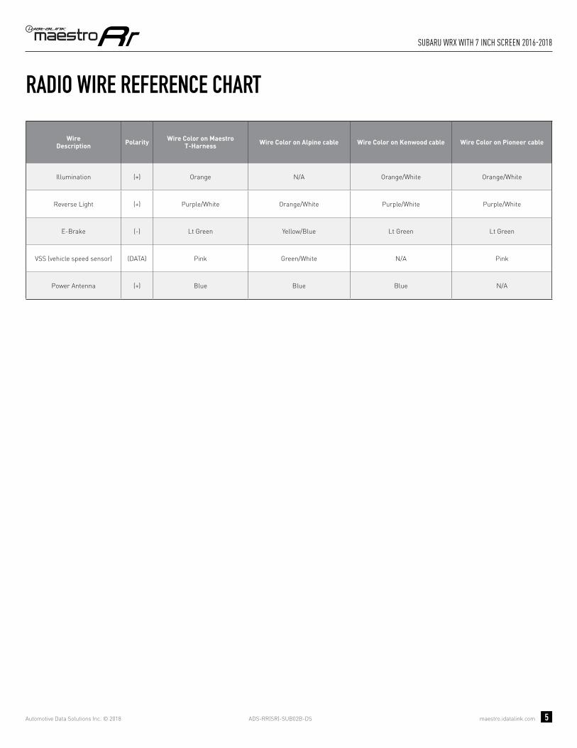
ADS-RR(SR)-SUB02B-DS maestro.idatalink.com
suBaRu wRX with 7 inch scReen 2016-2018
Automotive Data Solutions Inc. © 2018 5
RADIO WIRE REFERENCE CHART
WireDescription Polarity Wire Color on Maestro
T-Harness Wire Color on Alpine cable Wire Color on Kenwood cable Wire Color on Pioneer cable
Illumination (+) Orange N/A Orange/White Orange/White
Reverse Light (+) Purple/White Orange/White Purple/White Purple/White
E-Brake (-) Lt Green Yellow/Blue Lt Green Lt Green
VSS (vehicle speed sensor) (DATA) Pink Green/White N/A Pink
Power Antenna (+) Blue Blue Blue N/A

PROGRAMMED FIRMWAREADS-RR(SR)-SUB02B-DS
PRODUCTS REQUIREDiDatalink Maestro RR Radio Replacement InterfaceiDatalink Maestro SU2 Installation Harness
OPTIONAL ACCESSORIES
ACC-uSU2
Click here for: Radar Integration Installation GuideRadar Integration Owner’s Guide for Kenwood and JVC Radios
E L E C T R O N I C S
INSTALL GUIDESUBARU WRX
WITh 7 INCh SCREEN AND hARMAN KARDON
2016-2018Retains steeRing wheel contRols, amplifieR and moRe!
NOTICE: Automotive Data Solutions Inc. (ADS) recommends having this installation performed by a certified technician. Logos and trademarks used here in are the properties of their respective owners.

ADS-RR(SR)-SUB02B-DS maestro.idatalink.com
suBaRu wRX with 7 inch scReen and haRman KaRdon
Automotive Data Solutions Inc. © 2018 2
WELCOME
NEED hELP?
Congratulations on the purchase of your iDatalink Maestro RR Radio replacement solution. You are now a few simple steps away from enjoying your new car radio with enhanced features. Before starting your installation, please ensure that your iDatalink Maestro module is programmed with the correct fi rmware and that you carefully review the Installation Diagram and Vehicle Wire Refer-ence Chart.
Please note that Maestro RR will only retain functionalities that were originally available in the vehicle.
1 866 427-2999
maestro.idatalink.com/supportwww.12voltdata.com/forum
TABLE OF CONTENTS
Installation Instructions 3
Wiring Diagram 4
Radio Wire Reference Chart 5

ADS-RR(SR)-SUB02B-DS maestro.idatalink.com
suBaRu wRX with 7 inch scReen and haRman KaRdon
Automotive Data Solutions Inc. © 2018 3
INSTALLATION INSTRUCTIONS STEP 1
• Unbox the aftermarket radio and locate its main harness.
• Connect the wires from aftermarket radio main harness to the SU2 T-harness and match the wire functions.
• Remove the factory radio.
STEP 2
• Assemble the SU2 T-harness and connect it to the factory radio harness.
STEP 3Note: Connection required if the vehicle is equipped with Starlink telematics and a SOS button.
• Connect the BROWN Starlink wire to PINK or WHITE/BLUE (pin 8) of the 8 pin connector behind the OEM Radio.
STEP 4• Plug the OBDII connector into the OBDII of the vehicle,
under driver dash.
STEP 5• Plug the aftermarket radio harnesses into the aftermarket
radio.
• Plug the AUX cable to the aftermarket radio.
• Plug the RCA cable to the aftermarket radio.
• Plug the Data cable to the data port of the aftermarket radio.
• Insert the Audio cable into the iDatalink 3.5 mm audio jack of the aftermarket radio.
STEP 6• Connect all the harnesses to the Maestro RR module then
test your installation.
TROUBLESHOOTING TIPS:
• To reset the module back its factory settings, turn the key to the OFF position then disconnect all connectors from the module. Press and hold the module’s programming button and connect all the connectors back to the module. Wait, the module’s LED will fl ash RED rapidly (this may take up to 10 seconds). Release the programming button. Wait, the LED will turn solid GREEN for 2 seconds.
• For technical assistance call 1-866-427-2999 or e-mail “[email protected]”. Visit us at “maestro.idatalink.com/support” and “www.12voltdata.com/forum/”
7

ADS-RR(SR)-SUB02B-DS maestro.idatalink.com
suBaRu wRX with 7 inch scReen and haRman KaRdon
Automotive Data Solutions Inc. © 2018 4
7
BACKUP CAMBACKUP CAMCC
AA
AUXAUX
BB
D
GREENN.C.
MAESTRO RR MODULE
STEP 1
SU2 T-HARNESS
STEP 5
STEP 6STARLINK PINK OR WHITE/BLUE - 08
WIRING DIAGRAM
WIRES FROMVEHICLE
FACTORY RADIO HARNESS
8 PIN CONNECTOR BEHIND OEM RADIO
STEP 2
STEP 4
STEP 3
OBDII CONNECTOR
DATACABLE
AUDIOCABLE
CONNECT TOAFTERMARKET RADIO
CONNECTIONS NOT REQUIRED
BLUE
NC
NC
YELLOW
MAINHARNESS
YELLOW - 12V (+)
BLACK - GROUNDRED - ACCESSORY (+)
BLUE/WHITE - AMP. TURN ON (+)
ORANGE - ILLUMINATION (+)PURPLE/WHITE - REVERSE LIGHT (+)LTGREEN - E-BRAKE (-)
BLUE - POWER ANTENNAPINK - VEHICLE SPEED
SEE RADIO WIREREFERENCECHARTFOR RADIO WIRECOLORS
WHITEWHITE/BLACKGRAYGRAY/BLACKGREENGREEN/BLACK
PURPLE/BLACKPURPLE
LF RCA INPUT
RF RCA INPUT
LR RCA INPUT
RR RCA INPUT

ADS-RR(SR)-SUB02B-DS maestro.idatalink.com
suBaRu wRX with 7 inch scReen and haRman KaRdon
Automotive Data Solutions Inc. © 2018 5
RADIO WIRE REFERENCE CHART
WireDescription Polarity Wire Color on Maestro
T-Harness Wire Color on Alpine cable Wire Color on Kenwood cable Wire Color on Pioneer cable
Illumination (+) Orange N/A Orange/White Orange/White
Reverse Light (+) Purple/White Orange/White Purple/White Purple/White
E-Brake (-) Lt Green Yellow/Blue Lt Green Lt Green
VSS (vehicle speed sensor) (DATA) Pink Green/White N/A Pink
Power Antenna (+) Blue Blue Blue N/A

PROGRAMMED FIRMWAREADS-RR(SR)-SUB02B-DS
PRODUCTS REQUIREDiDatalink Maestro RR Radio Replacement InterfaceiDatalink Maestro SU2 Installation Harness
OPTIONAL ACCESSORIES
ACC-uSU2
Click here for: Radar Integration Installation GuideRadar Integration Owner’s Guide for Kenwood and JVC Radios
E L E C T R O N I C S
INSTALL GUIDESUBARU WRX
WITh NAV
2015Retains steeRing wheel contRols, amplifieR and moRe!
NOTICE: Automotive Data Solutions Inc. (ADS) recommends having this installation performed by a certified technician. Logos and trademarks used here in are the properties of their respective owners.

ADS-RR(SR)-SUB02B-DS maestro.idatalink.com
suBaRu wRX with naV 2015
Automotive Data Solutions Inc. © 2018 2
WELCOME
NEED hELP?
Congratulations on the purchase of your iDatalink Maestro RR Radio replacement solution. You are now a few simple steps away from enjoying your new car radio with enhanced features. Before starting your installation, please ensure that your iDatalink Maestro module is programmed with the correct fi rmware and that you carefully review the Installation Diagram and Vehicle Wire Refer-ence Chart.
Please note that Maestro RR will only retain functionalities that were originally available in the vehicle.
1 866 427-2999
maestro.idatalink.com/supportwww.12voltdata.com/forum
TABLE OF CONTENTS
Installation Instructions 3
Wiring Diagram 4
Radio Wire Reference Chart 5

ADS-RR(SR)-SUB02B-DS maestro.idatalink.com
suBaRu wRX with naV 2015
Automotive Data Solutions Inc. © 2018 3
INSTALLATION INSTRUCTIONS STEP 1
• Unbox the aftermarket radio and locate its main harness.
• Cut the WHITE, GRAY, GREEN and PURPLE RCA tips.
• Connect the wires from aftermarket radio main harness to the SU2 T-harness and match the wire functions.
• Remove the factory radio.
STEP 2
• Assemble the SU2 T-harness and connect it to the factory radio harness.
STEP 3Note: Connection required if the vehicle is equipped with Starlink telematics and a SOS button.
• Connect the BROWN Starlink wire to PINK or WHITE/BLUE (pin 8) of the 8 pin connector behind the OEM Radio.
STEP 4• Plug the OBDII connector into the OBDII of the vehicle,
under driver dash.
STEP 5• Plug the aftermarket radio harnesses into the aftermarket
radio.
• Plug the AUX cable to the aftermarket radio.
• Plug the RCA cable to the aftermarket radio.
• Plug the Data cable to the data port of the aftermarket radio.
• Insert the Audio cable into the iDatalink 3.5 mm audio jack of the aftermarket radio.
STEP 6• Connect all the harnesses to the Maestro RR module then
test your installation.
TROUBLESHOOTING TIPS:
• To reset the module back its factory settings, turn the key to the OFF position then disconnect all connectors from the module. Press and hold the module’s programming button and connect all the connectors back to the module. Wait, the module’s LED will fl ash RED rapidly (this may take up to 10 seconds). Release the programming button. Wait, the LED will turn solid GREEN for 2 seconds.
• For technical assistance call 1-866-427-2999 or e-mail “[email protected]”. Visit us at “maestro.idatalink.com/support” and “www.12voltdata.com/forum/”
5

ADS-RR(SR)-SUB02B-DS maestro.idatalink.com
suBaRu wRX with naV 2015
Automotive Data Solutions Inc. © 2018 4
5
BACKUP CAMBACKUP CAMCC
AA
AUXAUX
BB
D
GREENN.C.
MAESTRO RR MODULE
CUT AND REMOVE THE RCA JACKS
STEP 1
MAINHARNESS
SU2 T-HARNESS
WHITE - LF SPEAKER (+)WHITE/BLACK - LF SPEAKER (-)GRAY - RF SPEAKER (+)GRAY/BLACK - RF SPEAKER (-)GREEN - LR SPEAKER (+)GREEN/BLACK - LR SPEAKER (-)
PURPLE/BLACK - RR SPEAKER (-)
YELLOW - 12V (+)
BLACK - GROUNDRED - ACCESSORY (+)
BLUE/WHITE - AMP. TURN ON (+)
PURPLE - RR SPEAKER (+)
STEP 5
STEP 6
ORANGE - ILLUMINATION (+)PURPLE/WHITE - REVERSE LIGHT (+)LTGREEN - E-BRAKE (-)
BLUE - POWER ANTENNA
STARLINK PINK OR WHITE/BLUE - 08
PINK - VEHICLE SPEED
WIRING DIAGRAM
WIRES FROMVEHICLE
FACTORY RADIO HARNESS
8 PIN CONNECTOR BEHIND OEM RADIO
STEP 2
STEP 4
STEP 3
OBDII CONNECTOR
SEE RADIO WIREREFERENCECHARTFOR RADIO WIRECOLORS
DATACABLE
AUDIOCABLE
CONNECT TOAFTERMARKET RADIO
CONNECTIONS NOT REQUIRED
BLUE
NC
NC
YELLOW

ADS-RR(SR)-SUB02B-DS maestro.idatalink.com
suBaRu wRX with naV 2015
Automotive Data Solutions Inc. © 2018 5
RADIO WIRE REFERENCE CHART
WireDescription Polarity Wire Color on Maestro
T-Harness Wire Color on Alpine cable Wire Color on Kenwood cable Wire Color on Pioneer cable
Illumination (+) Orange N/A Orange/White Orange/White
Reverse Light (+) Purple/White Orange/White Purple/White Purple/White
E-Brake (-) Lt Green Yellow/Blue Lt Green Lt Green
VSS (vehicle speed sensor) (DATA) Pink Green/White N/A Pink
Power Antenna (+) Blue Blue Blue N/A
PROGRAMMED FIRMWAREADS-RR(SR)-SUB02B-DS
PRODUCTS REQUIREDiDatalink Maestro RR Radio Replacement InterfaceiDatalink Maestro SU2 Installation Harness
OPTIONAL ACCESSORIES
ACC-uSU2
Click here for: Radar Integration Installation GuideRadar Integration Owner’s Guide for Kenwood and JVC Radios
E L E C T R O N I C S
INSTALL GUIDESUBARU WRX
WITh NAV AND AMP
2015Retains steeRing wheel contRols, amplifieR and moRe!
NOTICE: Automotive Data Solutions Inc. (ADS) recommends having this installation performed by a certified technician. Logos and trademarks used here in are the properties of their respective owners.

ADS-RR(SR)-SUB02B-DS maestro.idatalink.com
suBaRu wRX with naV and amp 2015
Automotive Data Solutions Inc. © 2018 2
WELCOME
NEED hELP?
Congratulations on the purchase of your iDatalink Maestro RR Radio replacement solution. You are now a few simple steps away from enjoying your new car radio with enhanced features. Before starting your installation, please ensure that your iDatalink Maestro module is programmed with the correct fi rmware and that you carefully review the Installation Diagram and Vehicle Wire Refer-ence Chart.
Please note that Maestro RR will only retain functionalities that were originally available in the vehicle.
1 866 427-2999
maestro.idatalink.com/supportwww.12voltdata.com/forum
TABLE OF CONTENTS
Installation Instructions 3
Wiring Diagram 4
Radio Wire Reference Chart 5
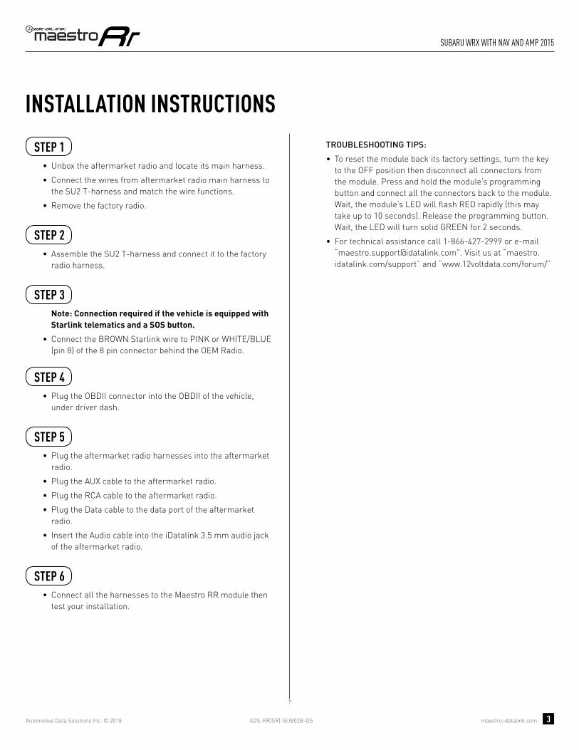
ADS-RR(SR)-SUB02B-DS maestro.idatalink.com
suBaRu wRX with naV and amp 2015
Automotive Data Solutions Inc. © 2018 3
INSTALLATION INSTRUCTIONS STEP 1
• Unbox the aftermarket radio and locate its main harness.
• Connect the wires from aftermarket radio main harness to the SU2 T-harness and match the wire functions.
• Remove the factory radio.
STEP 2
• Assemble the SU2 T-harness and connect it to the factory radio harness.
STEP 3Note: Connection required if the vehicle is equipped with Starlink telematics and a SOS button.
• Connect the BROWN Starlink wire to PINK or WHITE/BLUE (pin 8) of the 8 pin connector behind the OEM Radio.
STEP 4• Plug the OBDII connector into the OBDII of the vehicle,
under driver dash.
STEP 5• Plug the aftermarket radio harnesses into the aftermarket
radio.
• Plug the AUX cable to the aftermarket radio.
• Plug the RCA cable to the aftermarket radio.
• Plug the Data cable to the data port of the aftermarket radio.
• Insert the Audio cable into the iDatalink 3.5 mm audio jack of the aftermarket radio.
STEP 6• Connect all the harnesses to the Maestro RR module then
test your installation.
TROUBLESHOOTING TIPS:
• To reset the module back its factory settings, turn the key to the OFF position then disconnect all connectors from the module. Press and hold the module’s programming button and connect all the connectors back to the module. Wait, the module’s LED will fl ash RED rapidly (this may take up to 10 seconds). Release the programming button. Wait, the LED will turn solid GREEN for 2 seconds.
• For technical assistance call 1-866-427-2999 or e-mail “[email protected]”. Visit us at “maestro.idatalink.com/support” and “www.12voltdata.com/forum/”
7
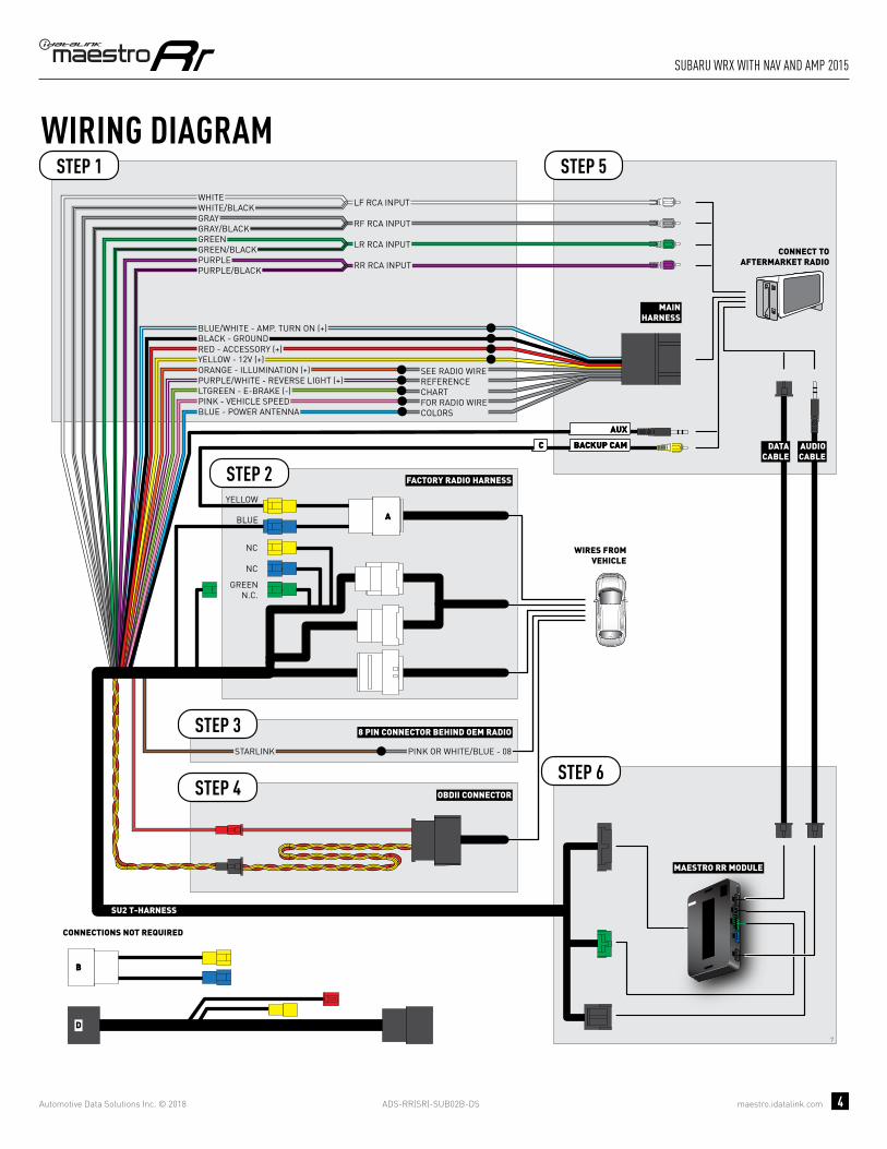
ADS-RR(SR)-SUB02B-DS maestro.idatalink.com
suBaRu wRX with naV and amp 2015
Automotive Data Solutions Inc. © 2018 4
7
BACKUP CAMBACKUP CAMCC
AA
AUXAUX
BB
D
GREENN.C.
MAESTRO RR MODULE
STEP 1
SU2 T-HARNESS
STEP 5
STEP 6STARLINK PINK OR WHITE/BLUE - 08
WIRING DIAGRAM
WIRES FROMVEHICLE
FACTORY RADIO HARNESS
8 PIN CONNECTOR BEHIND OEM RADIO
STEP 2
STEP 4
STEP 3
OBDII CONNECTOR
DATACABLE
AUDIOCABLE
CONNECT TOAFTERMARKET RADIO
CONNECTIONS NOT REQUIRED
BLUE
NC
NC
YELLOW
MAINHARNESS
YELLOW - 12V (+)
BLACK - GROUNDRED - ACCESSORY (+)
BLUE/WHITE - AMP. TURN ON (+)
ORANGE - ILLUMINATION (+)PURPLE/WHITE - REVERSE LIGHT (+)LTGREEN - E-BRAKE (-)
BLUE - POWER ANTENNAPINK - VEHICLE SPEED
SEE RADIO WIREREFERENCECHARTFOR RADIO WIRECOLORS
WHITEWHITE/BLACKGRAYGRAY/BLACKGREENGREEN/BLACK
PURPLE/BLACKPURPLE
LF RCA INPUT
RF RCA INPUT
LR RCA INPUT
RR RCA INPUT

ADS-RR(SR)-SUB02B-DS maestro.idatalink.com
suBaRu wRX with naV and amp 2015
Automotive Data Solutions Inc. © 2018 5
RADIO WIRE REFERENCE CHART
WireDescription Polarity Wire Color on Maestro
T-Harness Wire Color on Alpine cable Wire Color on Kenwood cable Wire Color on Pioneer cable
Illumination (+) Orange N/A Orange/White Orange/White
Reverse Light (+) Purple/White Orange/White Purple/White Purple/White
E-Brake (-) Lt Green Yellow/Blue Lt Green Lt Green
VSS (vehicle speed sensor) (DATA) Pink Green/White N/A Pink
Power Antenna (+) Blue Blue Blue N/A

PROGRAMMED FIRMWAREADS-RR(SR)-SUB02B-DS
PRODUCTS REQUIREDiDatalink Maestro RR Radio Replacement InterfaceiDatalink Maestro SU2 Installation Harness
OPTIONAL ACCESSORIES
ACC-uSU2
Click here for: Radar Integration Installation GuideRadar Integration Owner’s Guide for Kenwood and JVC Radios
E L E C T R O N I C S
INSTALL GUIDESUBARU XV CROSSTREK
WITh 6.2 INCh SCREEN
2015-2017Retains steeRing wheel contRols, amplifieR and moRe!
NOTICE: Automotive Data Solutions Inc. (ADS) recommends having this installation performed by a certified technician. Logos and trademarks used here in are the properties of their respective owners.

ADS-RR(SR)-SUB02B-DS maestro.idatalink.com
suBaRu XV cRosstReK with 6.2 inch scReen 2015-2017
Automotive Data Solutions Inc. © 2018 2
WELCOME
NEED hELP?
Congratulations on the purchase of your iDatalink Maestro RR Radio replacement solution. You are now a few simple steps away from enjoying your new car radio with enhanced features. Before starting your installation, please ensure that your iDatalink Maestro module is programmed with the correct fi rmware and that you carefully review the Installation Diagram and Vehicle Wire Refer-ence Chart.
Please note that Maestro RR will only retain functionalities that were originally available in the vehicle.
1 866 427-2999
maestro.idatalink.com/supportwww.12voltdata.com/forum
TABLE OF CONTENTS
Installation Instructions 3
Wiring Diagram 4
Radio Wire Reference Chart 5

ADS-RR(SR)-SUB02B-DS maestro.idatalink.com
suBaRu XV cRosstReK with 6.2 inch scReen 2015-2017
Automotive Data Solutions Inc. © 2018 3
INSTALLATION INSTRUCTIONS STEP 1
• Unbox the aftermarket radio and locate its main harness.
• Cut the WHITE, GRAY, GREEN and PURPLE RCA tips.
• Connect the wires from aftermarket radio main harness to the SU2 T-harness and match the wire functions.
• Remove the factory radio.
STEP 2
• Assemble the SU2 T-harness and connect it to the factory radio harness.
STEP 3Note: Connection required if the vehicle is equipped with Starlink telematics and a SOS button.
• Connect the BROWN Starlink wire to PINK or WHITE/BLUE (pin 8) of the 8 pin connector behind the OEM Radio.
STEP 4• Plug the OBDII connector into the OBDII of the vehicle,
under driver dash.
STEP 5• Plug the aftermarket radio harnesses into the aftermarket
radio.
• Plug the AUX cable to the aftermarket radio.
• Plug the RCA cable to the aftermarket radio.
• Plug the Data cable to the data port of the aftermarket radio.
• Insert the Audio cable into the iDatalink 3.5 mm audio jack of the aftermarket radio.
STEP 6• Connect all the harnesses to the Maestro RR module then
test your installation.
TROUBLESHOOTING TIPS:
• To reset the module back its factory settings, turn the key to the OFF position then disconnect all connectors from the module. Press and hold the module’s programming button and connect all the connectors back to the module. Wait, the module’s LED will fl ash RED rapidly (this may take up to 10 seconds). Release the programming button. Wait, the LED will turn solid GREEN for 2 seconds.
• For technical assistance call 1-866-427-2999 or e-mail “[email protected]”. Visit us at “maestro.idatalink.com/support” and “www.12voltdata.com/forum/”
4
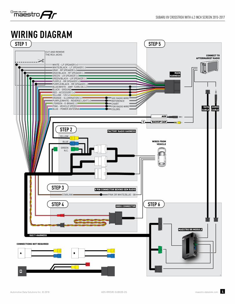
ADS-RR(SR)-SUB02B-DS maestro.idatalink.com
suBaRu XV cRosstReK with 6.2 inch scReen 2015-2017
Automotive Data Solutions Inc. © 2018 4
4
BACKUP CAMBACKUP CAMCC
AUXAUX
AA
D
BB
MAESTRO RR MODULE
CUT AND REMOVE THE RCA JACKS
STEP 1
MAINHARNESS
SU2 T-HARNESS
WHITE - LF SPEAKER (+)WHITE/BLACK - LF SPEAKER (-)GRAY - RF SPEAKER (+)GRAY/BLACK - RF SPEAKER (-)GREEN - LR SPEAKER (+)GREEN/BLACK - LR SPEAKER (-)
PURPLE/BLACK - RR SPEAKER (-)
YELLOW - 12V (+)
BLACK - GROUNDRED - ACCESSORY (+)
BLUE/WHITE - AMP. TURN ON (+)
PURPLE - RR SPEAKER (+)
STEP 5
STEP 6
ORANGE - ILLUMINATION (+)PURPLE/WHITE - REVERSE LIGHT (+)LTGREEN - E-BRAKE (-)
BLUE - POWER ANTENNAPINK - VEHICLE SPEED
WIRING DIAGRAM
WIRES FROMVEHICLE
FACTORY RADIO HARNESSSTEP 2
STEP 4 OBDII CONNECTOR
SEE RADIO WIREREFERENCECHARTFOR RADIO WIRECOLORS
DATACABLE
AUDIOCABLE
CONNECT TOAFTERMARKET RADIO
BLUE
GREENN.C.
CONNECTIONS NOT REQUIRED
YELLOW
STARLINK PINK OR WHITE/BLUE - 08
8 PIN CONNECTOR BEHIND OEM RADIOSTEP 3
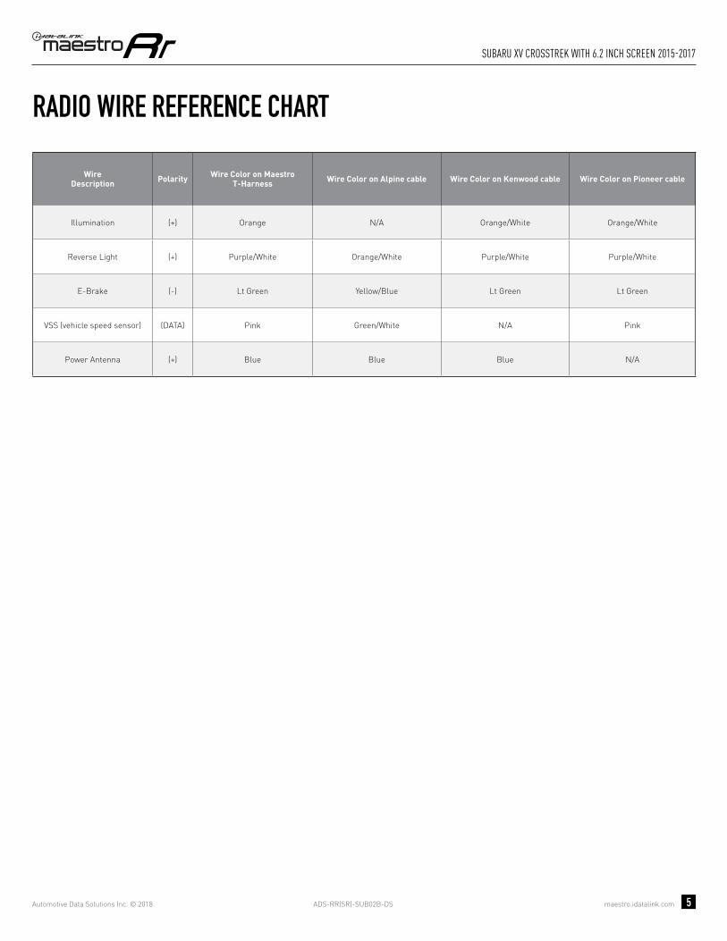
ADS-RR(SR)-SUB02B-DS maestro.idatalink.com
suBaRu XV cRosstReK with 6.2 inch scReen 2015-2017
Automotive Data Solutions Inc. © 2018 5
RADIO WIRE REFERENCE CHART
WireDescription Polarity Wire Color on Maestro
T-Harness Wire Color on Alpine cable Wire Color on Kenwood cable Wire Color on Pioneer cable
Illumination (+) Orange N/A Orange/White Orange/White
Reverse Light (+) Purple/White Orange/White Purple/White Purple/White
E-Brake (-) Lt Green Yellow/Blue Lt Green Lt Green
VSS (vehicle speed sensor) (DATA) Pink Green/White N/A Pink
Power Antenna (+) Blue Blue Blue N/A

PROGRAMMED FIRMWAREADS-RR(SR)-SUB02B-DS
PRODUCTS REQUIREDiDatalink Maestro RR Radio Replacement InterfaceiDatalink Maestro SU2 Installation Harness
OPTIONAL ACCESSORIES
ACC-uSU2
Click here for: Radar Integration Installation GuideRadar Integration Owner’s Guide for Kenwood and JVC Radios
E L E C T R O N I C S
INSTALL GUIDESUBARU XV CROSSTREKWITh 6.2 INCh SCREEN AND hARMAN KARDON
2015-2017Retains steeRing wheel contRols, amplifieR and moRe!
NOTICE: Automotive Data Solutions Inc. (ADS) recommends having this installation performed by a certified technician. Logos and trademarks used here in are the properties of their respective owners.

ADS-RR(SR)-SUB02B-DS maestro.idatalink.com
suBaRu XV cRosstReK
Automotive Data Solutions Inc. © 2018 2
WELCOME
NEED hELP?
Congratulations on the purchase of your iDatalink Maestro RR Radio replacement solution. You are now a few simple steps away from enjoying your new car radio with enhanced features. Before starting your installation, please ensure that your iDatalink Maestro module is programmed with the correct fi rmware and that you carefully review the Installation Diagram and Vehicle Wire Refer-ence Chart.
Please note that Maestro RR will only retain functionalities that were originally available in the vehicle.
1 866 427-2999
maestro.idatalink.com/supportwww.12voltdata.com/forum
TABLE OF CONTENTS
Installation Instructions 3
Wiring Diagram 4
Radio Wire Reference Chart 5

ADS-RR(SR)-SUB02B-DS maestro.idatalink.com
suBaRu XV cRosstReK
Automotive Data Solutions Inc. © 2018 3
INSTALLATION INSTRUCTIONS STEP 1
• Unbox the aftermarket radio and locate its main harness.
• Connect the wires from aftermarket radio main harness to the SU2 T-harness and match the wire functions.
• Remove the factory radio.
STEP 2
• Assemble the SU2 T-harness and connect it to the factory radio harness.
STEP 3Note: Connection required if the vehicle is equipped with Starlink telematics and a SOS button.
• Connect the BROWN Starlink wire to PINK or WHITE/BLUE (pin 8) of the 8 pin connector behind the OEM Radio.
STEP 4• Plug the OBDII connector into the OBDII of the vehicle,
under driver dash.
STEP 5• Plug the aftermarket radio harnesses into the aftermarket
radio.
• Plug the AUX cable to the aftermarket radio.
• Plug the RCA cable to the aftermarket radio.
• Plug the Data cable to the data port of the aftermarket radio.
• Insert the Audio cable into the iDatalink 3.5 mm audio jack of the aftermarket radio.
STEP 6• Connect all the harnesses to the Maestro RR module then
test your installation.
TROUBLESHOOTING TIPS:
• To reset the module back its factory settings, turn the key to the OFF position then disconnect all connectors from the module. Press and hold the module’s programming button and connect all the connectors back to the module. Wait, the module’s LED will fl ash RED rapidly (this may take up to 10 seconds). Release the programming button. Wait, the LED will turn solid GREEN for 2 seconds.
• For technical assistance call 1-866-427-2999 or e-mail “[email protected]”. Visit us at “maestro.idatalink.com/support” and “www.12voltdata.com/forum/”
6

ADS-RR(SR)-SUB02B-DS maestro.idatalink.com
suBaRu XV cRosstReK
Automotive Data Solutions Inc. © 2018 4
6
BACKUP CAMBACKUP CAMCC
AUXAUX
AA
D
BB
STARLINK PINK OR WHITE/BLUE - 08
8 PIN CONNECTOR BEHIND OEM RADIOSTEP 3
MAESTRO RR MODULE
STEP 1
SU2 T-HARNESS
STEP 5
STEP 6
WIRING DIAGRAM
WIRES FROMVEHICLE
FACTORY RADIO HARNESSSTEP 2
STEP 4 OBDII CONNECTOR
DATACABLE
AUDIOCABLE
CONNECT TOAFTERMARKET RADIO
BLUE
CONNECTIONS NOT REQUIRED
YELLOW
MAINHARNESS
YELLOW - 12V (+)
BLACK - GROUNDRED - ACCESSORY (+)
BLUE/WHITE - AMP. TURN ON (+)
ORANGE - ILLUMINATION (+)PURPLE/WHITE - REVERSE LIGHT (+)LTGREEN - E-BRAKE (-)
BLUE - POWER ANTENNAPINK - VEHICLE SPEED
SEE RADIO WIREREFERENCECHARTFOR RADIO WIRECOLORS
WHITEWHITE/BLACKGRAYGRAY/BLACKGREENGREEN/BLACK
PURPLE/BLACKPURPLE
LF RCA INPUT
RF RCA INPUT
LR RCA INPUT
RR RCA INPUT
RCA CABLES
GREENN.C.

ADS-RR(SR)-SUB02B-DS maestro.idatalink.com
suBaRu XV cRosstReK
Automotive Data Solutions Inc. © 2018 5
RADIO WIRE REFERENCE CHART
WireDescription Polarity Wire Color on Maestro
T-Harness Wire Color on Alpine cable Wire Color on Kenwood cable Wire Color on Pioneer cable
Illumination (+) Orange N/A Orange/White Orange/White
Reverse Light (+) Purple/White Orange/White Purple/White Purple/White
E-Brake (-) Lt Green Yellow/Blue Lt Green Lt Green
VSS (vehicle speed sensor) (DATA) Pink Green/White N/A Pink
Power Antenna (+) Blue Blue Blue N/A

PROGRAMMED FIRMWAREADS-RR(SR)-SUB02B-DS
PRODUCTS REQUIREDiDatalink Maestro RR Radio Replacement InterfaceiDatalink Maestro SU2 Installation Harness
OPTIONAL ACCESSORIES
ACC-uSU2
Click here for: Radar Integration Installation GuideRadar Integration Owner’s Guide for Kenwood and JVC Radios
E L E C T R O N I C S
INSTALL GUIDESUBARU XV CROSSTREK
WITh 7 INCh SCREEN
2015-2017Retains steeRing wheel contRols, amplifieR and moRe!
NOTICE: Automotive Data Solutions Inc. (ADS) recommends having this installation performed by a certified technician. Logos and trademarks used here in are the properties of their respective owners.

ADS-RR(SR)-SUB02B-DS maestro.idatalink.com
suBaRu XV cRosstReK with 7 inch scReen 2015-2017
Automotive Data Solutions Inc. © 2018 2
WELCOME
NEED hELP?
Congratulations on the purchase of your iDatalink Maestro RR Radio replacement solution. You are now a few simple steps away from enjoying your new car radio with enhanced features. Before starting your installation, please ensure that your iDatalink Maestro module is programmed with the correct fi rmware and that you carefully review the Installation Diagram and Vehicle Wire Refer-ence Chart.
Please note that Maestro RR will only retain functionalities that were originally available in the vehicle.
1 866 427-2999
maestro.idatalink.com/supportwww.12voltdata.com/forum
TABLE OF CONTENTS
Installation Instructions 3
Wiring Diagram 4
Radio Wire Reference Chart 5

ADS-RR(SR)-SUB02B-DS maestro.idatalink.com
suBaRu XV cRosstReK with 7 inch scReen 2015-2017
Automotive Data Solutions Inc. © 2018 3
INSTALLATION INSTRUCTIONS STEP 1
• Unbox the aftermarket radio and locate its main harness.
• Cut the WHITE, GRAY, GREEN and PURPLE RCA tips.
• Connect the wires from aftermarket radio main harness to the SU2 T-harness and match the wire functions.
• Remove the factory radio.
STEP 2
• Assemble the SU2 T-harness and connect it to the factory radio harness.
STEP 3Note: Connection required if the vehicle is equipped with Starlink telematics and a SOS button.
• Connect the BROWN Starlink wire to PINK or WHITE/BLUE (pin 8) of the 8 pin connector behind the OEM Radio.
STEP 4• Plug the OBDII connector into the OBDII of the vehicle,
under driver dash.
STEP 5• Plug the aftermarket radio harnesses into the aftermarket
radio.
• Plug the AUX cable to the aftermarket radio.
• Plug the RCA cable to the aftermarket radio.
• Plug the Data cable to the data port of the aftermarket radio.
• Insert the Audio cable into the iDatalink 3.5 mm audio jack of the aftermarket radio.
STEP 6• Connect all the harnesses to the Maestro RR module then
test your installation.
TROUBLESHOOTING TIPS:
• To reset the module back its factory settings, turn the key to the OFF position then disconnect all connectors from the module. Press and hold the module’s programming button and connect all the connectors back to the module. Wait, the module’s LED will fl ash RED rapidly (this may take up to 10 seconds). Release the programming button. Wait, the LED will turn solid GREEN for 2 seconds.
• For technical assistance call 1-866-427-2999 or e-mail “[email protected]”. Visit us at “maestro.idatalink.com/support” and “www.12voltdata.com/forum/”
5

ADS-RR(SR)-SUB02B-DS maestro.idatalink.com
suBaRu XV cRosstReK with 7 inch scReen 2015-2017
Automotive Data Solutions Inc. © 2018 4
5
BACKUP CAMBACKUP CAMCC
AA
AUXAUX
BB
D
GREENN.C.
MAESTRO RR MODULE
CUT AND REMOVE THE RCA JACKS
STEP 1
MAINHARNESS
SU2 T-HARNESS
WHITE - LF SPEAKER (+)WHITE/BLACK - LF SPEAKER (-)GRAY - RF SPEAKER (+)GRAY/BLACK - RF SPEAKER (-)GREEN - LR SPEAKER (+)GREEN/BLACK - LR SPEAKER (-)
PURPLE/BLACK - RR SPEAKER (-)
YELLOW - 12V (+)
BLACK - GROUNDRED - ACCESSORY (+)
BLUE/WHITE - AMP. TURN ON (+)
PURPLE - RR SPEAKER (+)
STEP 5
STEP 6
ORANGE - ILLUMINATION (+)PURPLE/WHITE - REVERSE LIGHT (+)LTGREEN - E-BRAKE (-)
BLUE - POWER ANTENNA
STARLINK PINK OR WHITE/BLUE - 08
PINK - VEHICLE SPEED
WIRING DIAGRAM
WIRES FROMVEHICLE
FACTORY RADIO HARNESS
8 PIN CONNECTOR BEHIND OEM RADIO
STEP 2
STEP 4
STEP 3
OBDII CONNECTOR
SEE RADIO WIREREFERENCECHARTFOR RADIO WIRECOLORS
DATACABLE
AUDIOCABLE
CONNECT TOAFTERMARKET RADIO
CONNECTIONS NOT REQUIRED
BLUE
NC
NC
YELLOW

ADS-RR(SR)-SUB02B-DS maestro.idatalink.com
suBaRu XV cRosstReK with 7 inch scReen 2015-2017
Automotive Data Solutions Inc. © 2018 5
RADIO WIRE REFERENCE CHART
WireDescription Polarity Wire Color on Maestro
T-Harness Wire Color on Alpine cable Wire Color on Kenwood cable Wire Color on Pioneer cable
Illumination (+) Orange N/A Orange/White Orange/White
Reverse Light (+) Purple/White Orange/White Purple/White Purple/White
E-Brake (-) Lt Green Yellow/Blue Lt Green Lt Green
VSS (vehicle speed sensor) (DATA) Pink Green/White N/A Pink
Power Antenna (+) Blue Blue Blue N/A

PROGRAMMED FIRMWAREADS-RR(SR)-SUB02B-DS
PRODUCTS REQUIREDiDatalink Maestro RR Radio Replacement InterfaceiDatalink Maestro SU2 Installation Harness
OPTIONAL ACCESSORIES
ACC-uSU2
Click here for: Radar Integration Installation GuideRadar Integration Owner’s Guide for Kenwood and JVC Radios
E L E C T R O N I C S
INSTALL GUIDESUBARU XV CROSSTREK
WITh 7 INCh SCREEN AND hARMAN KARDON
2015-2017Retains steeRing wheel contRols, amplifieR and moRe!
NOTICE: Automotive Data Solutions Inc. (ADS) recommends having this installation performed by a certified technician. Logos and trademarks used here in are the properties of their respective owners.

ADS-RR(SR)-SUB02B-DS maestro.idatalink.com
suBaRu XV cRosstReK
Automotive Data Solutions Inc. © 2018 2
WELCOME
NEED hELP?
Congratulations on the purchase of your iDatalink Maestro RR Radio replacement solution. You are now a few simple steps away from enjoying your new car radio with enhanced features. Before starting your installation, please ensure that your iDatalink Maestro module is programmed with the correct fi rmware and that you carefully review the Installation Diagram and Vehicle Wire Refer-ence Chart.
Please note that Maestro RR will only retain functionalities that were originally available in the vehicle.
1 866 427-2999
maestro.idatalink.com/supportwww.12voltdata.com/forum
TABLE OF CONTENTS
Installation Instructions 3
Wiring Diagram 4
Radio Wire Reference Chart 5
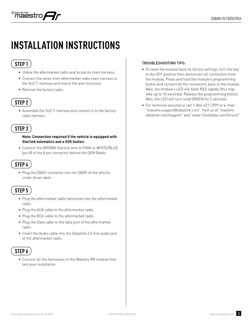
ADS-RR(SR)-SUB02B-DS maestro.idatalink.com
suBaRu XV cRosstReK
Automotive Data Solutions Inc. © 2018 3
INSTALLATION INSTRUCTIONS STEP 1
• Unbox the aftermarket radio and locate its main harness.
• Connect the wires from aftermarket radio main harness to the SU2 T-harness and match the wire functions.
• Remove the factory radio.
STEP 2
• Assemble the SU2 T-harness and connect it to the factory radio harness.
STEP 3Note: Connection required if the vehicle is equipped with Starlink telematics and a SOS button.
• Connect the BROWN Starlink wire to PINK or WHITE/BLUE (pin 8) of the 8 pin connector behind the OEM Radio.
STEP 4• Plug the OBDII connector into the OBDII of the vehicle,
under driver dash.
STEP 5• Plug the aftermarket radio harnesses into the aftermarket
radio.
• Plug the AUX cable to the aftermarket radio.
• Plug the RCA cable to the aftermarket radio.
• Plug the Data cable to the data port of the aftermarket radio.
• Insert the Audio cable into the iDatalink 3.5 mm audio jack of the aftermarket radio.
STEP 6• Connect all the harnesses to the Maestro RR module then
test your installation.
TROUBLESHOOTING TIPS:
• To reset the module back its factory settings, turn the key to the OFF position then disconnect all connectors from the module. Press and hold the module’s programming button and connect all the connectors back to the module. Wait, the module’s LED will fl ash RED rapidly (this may take up to 10 seconds). Release the programming button. Wait, the LED will turn solid GREEN for 2 seconds.
• For technical assistance call 1-866-427-2999 or e-mail “[email protected]”. Visit us at “maestro.idatalink.com/support” and “www.12voltdata.com/forum/”
7

ADS-RR(SR)-SUB02B-DS maestro.idatalink.com
suBaRu XV cRosstReK
Automotive Data Solutions Inc. © 2018 4
7
BACKUP CAMBACKUP CAMCC
AA
AUXAUX
BB
D
GREENN.C.
MAESTRO RR MODULE
STEP 1
SU2 T-HARNESS
STEP 5
STEP 6STARLINK PINK OR WHITE/BLUE - 08
WIRING DIAGRAM
WIRES FROMVEHICLE
FACTORY RADIO HARNESS
8 PIN CONNECTOR BEHIND OEM RADIO
STEP 2
STEP 4
STEP 3
OBDII CONNECTOR
DATACABLE
AUDIOCABLE
CONNECT TOAFTERMARKET RADIO
CONNECTIONS NOT REQUIRED
BLUE
NC
NC
YELLOW
MAINHARNESS
YELLOW - 12V (+)
BLACK - GROUNDRED - ACCESSORY (+)
BLUE/WHITE - AMP. TURN ON (+)
ORANGE - ILLUMINATION (+)PURPLE/WHITE - REVERSE LIGHT (+)LTGREEN - E-BRAKE (-)
BLUE - POWER ANTENNAPINK - VEHICLE SPEED
SEE RADIO WIREREFERENCECHARTFOR RADIO WIRECOLORS
WHITEWHITE/BLACKGRAYGRAY/BLACKGREENGREEN/BLACK
PURPLE/BLACKPURPLE
LF RCA INPUT
RF RCA INPUT
LR RCA INPUT
RR RCA INPUT

ADS-RR(SR)-SUB02B-DS maestro.idatalink.com
suBaRu XV cRosstReK
Automotive Data Solutions Inc. © 2018 5
RADIO WIRE REFERENCE CHART
WireDescription Polarity Wire Color on Maestro
T-Harness Wire Color on Alpine cable Wire Color on Kenwood cable Wire Color on Pioneer cable
Illumination (+) Orange N/A Orange/White Orange/White
Reverse Light (+) Purple/White Orange/White Purple/White Purple/White
E-Brake (-) Lt Green Yellow/Blue Lt Green Lt Green
VSS (vehicle speed sensor) (DATA) Pink Green/White N/A Pink
Power Antenna (+) Blue Blue Blue N/A

PROGRAMMED FIRMWAREADS-RR(SR)-SUB02B-DS
PRODUCTS REQUIREDiDatalink Maestro RR Radio Replacement InterfaceiDatalink Maestro SU2 Installation Harness
OPTIONAL ACCESSORIES
ACC-uSU2
Click here for: Radar Integration Installation GuideRadar Integration Owner’s Guide for Kenwood and JVC Radios
E L E C T R O N I C S
INSTALL GUIDESUBARU XV CROSSTREK
WITh hARMAN KARDON AND OEM CAMERA ON RADIO
2013-2014Retains steeRing wheel contRols, amplifieR and moRe!
NOTICE: Automotive Data Solutions Inc. (ADS) recommends having this installation performed by a certified technician. Logos and trademarks used here in are the properties of their respective owners.

ADS-RR(SR)-SUB02B-DS maestro.idatalink.com
suBaRu XV cRosstReK
Automotive Data Solutions Inc. © 2018 2
WELCOME
NEED hELP?
Congratulations on the purchase of your iDatalink Maestro RR Radio replacement solution. You are now a few simple steps away from enjoying your new car radio with enhanced features. Before starting your installation, please ensure that your iDatalink Maestro module is programmed with the correct fi rmware and that you carefully review the Installation Diagram and Vehicle Wire Refer-ence Chart.
Please note that Maestro RR will only retain functionalities that were originally available in the vehicle.
1 866 427-2999
maestro.idatalink.com/supportwww.12voltdata.com/forum
TABLE OF CONTENTS
Installation Instructions 3
Wiring Diagram 4
Radio Wire Reference Chart 5

ADS-RR(SR)-SUB02B-DS maestro.idatalink.com
suBaRu XV cRosstReK
Automotive Data Solutions Inc. © 2018 3
INSTALLATION INSTRUCTIONS STEP 1
• Unbox the aftermarket radio and locate its main harness.
• Connect the wires from aftermarket radio main harness to the SU2 T-harness and match the wire functions.
• Remove the factory radio.
STEP 2
• Assemble the SU2 T-harness and connect it to the factory radio harness.
STEP 3• Plug the OBDII connector into the OBDII of the vehicle,
under driver dash.
STEP 4• Plug the aftermarket radio harnesses into the aftermarket
radio.
• Plug the AUX cable to the aftermarket radio.
• Plug the RCA cable to the aftermarket radio.
• Plug the Data cable to the data port of the aftermarket radio.
• Insert the Audio cable into the iDatalink 3.5 mm audio jack of the aftermarket radio.
STEP 5• Connect all the harnesses to the Maestro RR module then
test your installation.
TROUBLESHOOTING TIPS:
• To reset the module back its factory settings, turn the key to the OFF position then disconnect all connectors from the module. Press and hold the module’s programming button and connect all the connectors back to the module. Wait, the module’s LED will fl ash RED rapidly (this may take up to 10 seconds). Release the programming button. Wait, the LED will turn solid GREEN for 2 seconds.
• For technical assistance call 1-866-427-2999 or e-mail “[email protected]”. Visit us at “maestro.idatalink.com/support” and “www.12voltdata.com/forum/”
8

ADS-RR(SR)-SUB02B-DS maestro.idatalink.com
suBaRu XV cRosstReK
Automotive Data Solutions Inc. © 2018 4
8
BACKUP CAMBACKUP CAMCC
BB
AUXAUX
AA
D
GREENN.C.
MAESTRO RR MODULE
STEP 1
SU2 T-HARNESS
STEP 4
STEP 5
STARLINK (N.C.)
WIRING DIAGRAM
WIRES FROMVEHICLE
FACTORY RADIO HARNESSSTEP 2
STEP 3 OBDII CONNECTOR
DATACABLE
AUDIOCABLE
CONNECT TOAFTERMARKET RADIO
CONNECTIONS NOT REQUIRED
BLUE
NC
NC
YELLOW
MAINHARNESS
YELLOW - 12V (+)
BLACK - GROUNDRED - ACCESSORY (+)
BLUE/WHITE - AMP. TURN ON (+)
ORANGE - ILLUMINATION (+)PURPLE/WHITE - REVERSE LIGHT (+)LTGREEN - E-BRAKE (-)
BLUE - POWER ANTENNAPINK - VEHICLE SPEED
SEE RADIO WIREREFERENCECHARTFOR RADIO WIRECOLORS
WHITEWHITE/BLACKGRAYGRAY/BLACKGREENGREEN/BLACK
PURPLE/BLACKPURPLE
LF RCA INPUT
RF RCA INPUT
LR RCA INPUT
RR RCA INPUT

ADS-RR(SR)-SUB02B-DS maestro.idatalink.com
suBaRu XV cRosstReK
Automotive Data Solutions Inc. © 2018 5
RADIO WIRE REFERENCE CHART
WireDescription Polarity Wire Color on Maestro
T-Harness Wire Color on Alpine cable Wire Color on Kenwood cable Wire Color on Pioneer cable
Illumination (+) Orange N/A Orange/White Orange/White
Reverse Light (+) Purple/White Orange/White Purple/White Purple/White
E-Brake (-) Lt Green Yellow/Blue Lt Green Lt Green
VSS (vehicle speed sensor) (DATA) Pink Green/White N/A Pink
Power Antenna (+) Blue Blue Blue N/A

PROGRAMMED FIRMWAREADS-RR(SR)-SUB02B-DS
PRODUCTS REQUIREDiDatalink Maestro RR Radio Replacement InterfaceiDatalink Maestro SU2 Installation Harness
OPTIONAL ACCESSORIES
ACC-uSU2
Click here for: Radar Integration Installation GuideRadar Integration Owner’s Guide for Kenwood and JVC Radios
E L E C T R O N I C S
INSTALL GUIDESUBARU XV CROSSTREK
WITh NAV AND hARMAN KARDON AND OEM CAMERA ON SECONDARy DISPLAy
2013-2014Retains steeRing wheel contRols, amplifieR and moRe!
NOTICE: Automotive Data Solutions Inc. (ADS) recommends having this installation performed by a certified technician. Logos and trademarks used here in are the properties of their respective owners.

ADS-RR(SR)-SUB02B-DS maestro.idatalink.com
suBaRu XV cRosstReK
Automotive Data Solutions Inc. © 2018 2
WELCOME
NEED hELP?
Congratulations on the purchase of your iDatalink Maestro RR Radio replacement solution. You are now a few simple steps away from enjoying your new car radio with enhanced features. Before starting your installation, please ensure that your iDatalink Maestro module is programmed with the correct fi rmware and that you carefully review the Installation Diagram and Vehicle Wire Refer-ence Chart.
Please note that Maestro RR will only retain functionalities that were originally available in the vehicle.
1 866 427-2999
maestro.idatalink.com/supportwww.12voltdata.com/forum
TABLE OF CONTENTS
Installation Instructions 3
Wiring Diagram 4
Radio Wire Reference Chart 5

ADS-RR(SR)-SUB02B-DS maestro.idatalink.com
suBaRu XV cRosstReK
Automotive Data Solutions Inc. © 2018 3
INSTALLATION INSTRUCTIONS STEP 1
• Unbox the aftermarket radio and locate its main harness.
• Connect the wires from aftermarket radio main harness to the SU2 T-harness and match the wire functions.
• Remove the factory radio.
STEP 2
• Assemble the SU2 T-harness and connect it to the factory radio harness.
STEP 3• Plug the OBDII connector into the OBDII of the vehicle,
under driver dash.
STEP 4• Plug the aftermarket radio harnesses into the aftermarket
radio.
• Plug the AUX cable to the aftermarket radio.
• Plug the RCA cable to the aftermarket radio.
• Plug the Data cable to the data port of the aftermarket radio.
• Insert the Audio cable into the iDatalink 3.5 mm audio jack of the aftermarket radio.
STEP 5• Connect all the harnesses to the Maestro RR module then
test your installation.
TROUBLESHOOTING TIPS:
• To reset the module back its factory settings, turn the key to the OFF position then disconnect all connectors from the module. Press and hold the module’s programming button and connect all the connectors back to the module. Wait, the module’s LED will fl ash RED rapidly (this may take up to 10 seconds). Release the programming button. Wait, the LED will turn solid GREEN for 2 seconds.
• For technical assistance call 1-866-427-2999 or e-mail “[email protected]”. Visit us at “maestro.idatalink.com/support” and “www.12voltdata.com/forum/”
3

ADS-RR(SR)-SUB02B-DS maestro.idatalink.com
suBaRu XV cRosstReK
Automotive Data Solutions Inc. © 2018 4
3
D
BACKUP CAMBACKUP CAMCC
AUXAUX
AA BB
MAESTRO RR MODULE
STEP 1
SU2 T-HARNESS
STEP 4
STEP 5
WIRING DIAGRAM
WIRES FROMVEHICLE
FACTORY RADIO HARNESSSTEP 2
STEP 3 OBDII CONNECTOR
CONNECT TO SECONDARYSCREEN HARNESS IF EQUIPPED
WITH A BACKUP CAMERA
DATACABLE
AUDIOCABLE
CONNECT TOAFTERMARKET RADIO
BLUE
GREENN.C.
N.C.
CONNECTIONS NOT REQUIRED
YELLOWN.C.
YELLOW
RED
MAINHARNESS
YELLOW - 12V (+)
BLACK - GROUNDRED - ACCESSORY (+)
BLUE/WHITE - AMP. TURN ON (+)
ORANGE - ILLUMINATION (+)PURPLE/WHITE - REVERSE LIGHT (+)LTGREEN - E-BRAKE (-)
BLUE - POWER ANTENNAPINK - VEHICLE SPEED
SEE RADIO WIREREFERENCECHARTFOR RADIO WIRECOLORS
WHITEWHITE/BLACKGRAYGRAY/BLACKGREENGREEN/BLACK
PURPLE/BLACKPURPLE
LF RCA INPUT
RF RCA INPUT
LR RCA INPUT
RR RCA INPUT
STARLINK (N.C.)

ADS-RR(SR)-SUB02B-DS maestro.idatalink.com
suBaRu XV cRosstReK
Automotive Data Solutions Inc. © 2018 5
RADIO WIRE REFERENCE CHART
WireDescription Polarity Wire Color on Maestro
T-Harness Wire Color on Alpine cable Wire Color on Kenwood cable Wire Color on Pioneer cable
Illumination (+) Orange N/A Orange/White Orange/White
Reverse Light (+) Purple/White Orange/White Purple/White Purple/White
E-Brake (-) Lt Green Yellow/Blue Lt Green Lt Green
VSS (vehicle speed sensor) (DATA) Pink Green/White N/A Pink
Power Antenna (+) Blue Blue Blue N/A

PROGRAMMED FIRMWAREADS-RR(SR)-SUB02B-DS
PRODUCTS REQUIREDiDatalink Maestro RR Radio Replacement InterfaceiDatalink Maestro SU2 Installation Harness
OPTIONAL ACCESSORIES
ACC-uSU2
Click here for: Radar Integration Installation GuideRadar Integration Owner’s Guide for Kenwood and JVC Radios
E L E C T R O N I C S
INSTALL GUIDESUBARU XV CROSSTREK
WITh NAV AND OEM CAMERA ON SECONDARy DISPLAy
2013-2014Retains steeRing wheel contRols, amplifieR and moRe!
NOTICE: Automotive Data Solutions Inc. (ADS) recommends having this installation performed by a certified technician. Logos and trademarks used here in are the properties of their respective owners.

ADS-RR(SR)-SUB02B-DS maestro.idatalink.com
suBaRu XV cRosstReK
Automotive Data Solutions Inc. © 2018 2
WELCOME
NEED hELP?
Congratulations on the purchase of your iDatalink Maestro RR Radio replacement solution. You are now a few simple steps away from enjoying your new car radio with enhanced features. Before starting your installation, please ensure that your iDatalink Maestro module is programmed with the correct fi rmware and that you carefully review the Installation Diagram and Vehicle Wire Refer-ence Chart.
Please note that Maestro RR will only retain functionalities that were originally available in the vehicle.
1 866 427-2999
maestro.idatalink.com/supportwww.12voltdata.com/forum
TABLE OF CONTENTS
Installation Instructions 3
Wiring Diagram 4
Radio Wire Reference Chart 5

ADS-RR(SR)-SUB02B-DS maestro.idatalink.com
suBaRu XV cRosstReK
Automotive Data Solutions Inc. © 2018 3
INSTALLATION INSTRUCTIONS STEP 1
• Unbox the aftermarket radio and locate its main harness.
• Cut the WHITE, GRAY, GREEN and PURPLE RCA tips.
• Connect the wires from aftermarket radio main harness to the SU2 T-harness and match the wire functions.
• Remove the factory radio.
STEP 2
• Assemble the SU2 T-harness and connect it to the factory radio harness.
STEP 3• Plug the OBDII connector into the OBDII of the vehicle,
under driver dash.
STEP 4• Plug the aftermarket radio harnesses into the aftermarket
radio.
• Plug the AUX cable to the aftermarket radio.
• Plug the RCA cable to the aftermarket radio.
• Plug the Data cable to the data port of the aftermarket radio.
• Insert the Audio cable into the iDatalink 3.5 mm audio jack of the aftermarket radio.
STEP 5• Connect all the harnesses to the Maestro RR module then
test your installation.
TROUBLESHOOTING TIPS:
• To reset the module back its factory settings, turn the key to the OFF position then disconnect all connectors from the module. Press and hold the module’s programming button and connect all the connectors back to the module. Wait, the module’s LED will fl ash RED rapidly (this may take up to 10 seconds). Release the programming button. Wait, the LED will turn solid GREEN for 2 seconds.
• For technical assistance call 1-866-427-2999 or e-mail “[email protected]”. Visit us at “maestro.idatalink.com/support” and “www.12voltdata.com/forum/”
2

ADS-RR(SR)-SUB02B-DS maestro.idatalink.com
suBaRu XV cRosstReK
Automotive Data Solutions Inc. © 2018 4
2
D
BACKUP CAMBACKUP CAMCC
AUXAUX
AA BB
MAESTRO RR MODULE
CUT AND REMOVE THE RCA JACKS
STEP 1
MAINHARNESS
SU2 T-HARNESS
WHITE - LF SPEAKER (+)WHITE/BLACK - LF SPEAKER (-)GRAY - RF SPEAKER (+)GRAY/BLACK - RF SPEAKER (-)GREEN - LR SPEAKER (+)GREEN/BLACK - LR SPEAKER (-)
PURPLE/BLACK - RR SPEAKER (-)
YELLOW - 12V (+)
BLACK - GROUNDRED - ACCESSORY (+)
BLUE/WHITE - AMP. TURN ON (+)
PURPLE - RR SPEAKER (+)
STEP 4
STEP 5
ORANGE - ILLUMINATION (+)PURPLE/WHITE - REVERSE LIGHT (+)LTGREEN - E-BRAKE (-)
BLUE - POWER ANTENNAPINK - VEHICLE SPEED
WIRING DIAGRAM
WIRES FROMVEHICLE
FACTORY RADIO HARNESSSTEP 2
STEP 3 OBDII CONNECTOR
SEE RADIO WIREREFERENCECHARTFOR RADIO WIRECOLORS
CONNECT TO SECONDARYSCREEN HARNESS IF EQUIPPED
WITH A BACKUP CAMERA
DATACABLE
AUDIOCABLE
CONNECT TOAFTERMARKET RADIO
BLUE
GREENN.C.
N.C.
CONNECTIONS NOT REQUIRED
YELLOWN.C.
YELLOW
RED
STARLINK (N.C.)

ADS-RR(SR)-SUB02B-DS maestro.idatalink.com
suBaRu XV cRosstReK
Automotive Data Solutions Inc. © 2018 5
RADIO WIRE REFERENCE CHART
WireDescription Polarity Wire Color on Maestro
T-Harness Wire Color on Alpine cable Wire Color on Kenwood cable Wire Color on Pioneer cable
Illumination (+) Orange N/A Orange/White Orange/White
Reverse Light (+) Purple/White Orange/White Purple/White Purple/White
E-Brake (-) Lt Green Yellow/Blue Lt Green Lt Green
VSS (vehicle speed sensor) (DATA) Pink Green/White N/A Pink
Power Antenna (+) Blue Blue Blue N/A

PROGRAMMED FIRMWAREADS-RR(SR)-SUB02B-DS
PRODUCTS REQUIREDiDatalink Maestro RR Radio Replacement InterfaceiDatalink Maestro SU2 Installation Harness
OPTIONAL ACCESSORIES
ACC-uSU2
Click here for: Radar Integration Installation GuideRadar Integration Owner’s Guide for Kenwood and JVC Radios
E L E C T R O N I C S
INSTALL GUIDESUBARU XV CROSSTREK
WITh OEM CAMERA ON RADIO
2013-2014Retains steeRing wheel contRols, amplifieR and moRe!
NOTICE: Automotive Data Solutions Inc. (ADS) recommends having this installation performed by a certified technician. Logos and trademarks used here in are the properties of their respective owners.
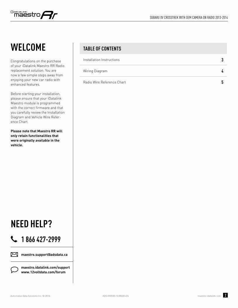
ADS-RR(SR)-SUB02B-DS maestro.idatalink.com
suBaRu XV cRosstReK with oem cameRa on Radio 2013-2014
Automotive Data Solutions Inc. © 2018 2
WELCOME
NEED hELP?
Congratulations on the purchase of your iDatalink Maestro RR Radio replacement solution. You are now a few simple steps away from enjoying your new car radio with enhanced features. Before starting your installation, please ensure that your iDatalink Maestro module is programmed with the correct fi rmware and that you carefully review the Installation Diagram and Vehicle Wire Refer-ence Chart.
Please note that Maestro RR will only retain functionalities that were originally available in the vehicle.
1 866 427-2999
maestro.idatalink.com/supportwww.12voltdata.com/forum
TABLE OF CONTENTS
Installation Instructions 3
Wiring Diagram 4
Radio Wire Reference Chart 5

ADS-RR(SR)-SUB02B-DS maestro.idatalink.com
suBaRu XV cRosstReK with oem cameRa on Radio 2013-2014
Automotive Data Solutions Inc. © 2018 3
INSTALLATION INSTRUCTIONS STEP 1
• Unbox the aftermarket radio and locate its main harness.
• Cut the WHITE, GRAY, GREEN and PURPLE RCA tips.
• Connect the wires from aftermarket radio main harness to the SU2 T-harness and match the wire functions.
• Remove the factory radio.
STEP 2
• Assemble the SU2 T-harness and connect it to the factory radio harness.
STEP 3• Plug the OBDII connector into the OBDII of the vehicle,
under driver dash.
STEP 4• Plug the aftermarket radio harnesses into the aftermarket
radio.
• Plug the AUX cable to the aftermarket radio.
• Plug the RCA cable to the aftermarket radio.
• Plug the Data cable to the data port of the aftermarket radio.
• Insert the Audio cable into the iDatalink 3.5 mm audio jack of the aftermarket radio.
STEP 5• Connect all the harnesses to the Maestro RR module then
test your installation.
TROUBLESHOOTING TIPS:
• To reset the module back its factory settings, turn the key to the OFF position then disconnect all connectors from the module. Press and hold the module’s programming button and connect all the connectors back to the module. Wait, the module’s LED will fl ash RED rapidly (this may take up to 10 seconds). Release the programming button. Wait, the LED will turn solid GREEN for 2 seconds.
• For technical assistance call 1-866-427-2999 or e-mail “[email protected]”. Visit us at “maestro.idatalink.com/support” and “www.12voltdata.com/forum/”
1

ADS-RR(SR)-SUB02B-DS maestro.idatalink.com
suBaRu XV cRosstReK with oem cameRa on Radio 2013-2014
Automotive Data Solutions Inc. © 2018 4
1
BACKUP CAMBACKUP CAMCC
AUXAUX
AA
D
BB
MAESTRO RR MODULE
CUT AND REMOVE THE RCA JACKS
STEP 1
MAINHARNESS
SU2 T-HARNESS
WHITE - LF SPEAKER (+)WHITE/BLACK - LF SPEAKER (-)GRAY - RF SPEAKER (+)GRAY/BLACK - RF SPEAKER (-)GREEN - LR SPEAKER (+)GREEN/BLACK - LR SPEAKER (-)
PURPLE/BLACK - RR SPEAKER (-)
YELLOW - 12V (+)
BLACK - GROUNDRED - ACCESSORY (+)
BLUE/WHITE - AMP. TURN ON (+)
PURPLE - RR SPEAKER (+)
STEP 4
STEP 5
ORANGE - ILLUMINATION (+)PURPLE/WHITE - REVERSE LIGHT (+)LTGREEN - E-BRAKE (-)
BLUE - POWER ANTENNAPINK - VEHICLE SPEED
WIRING DIAGRAM
WIRES FROMVEHICLE
FACTORY RADIO HARNESSSTEP 2
STEP 3 OBDII CONNECTOR
SEE RADIO WIREREFERENCECHARTFOR RADIO WIRECOLORS
DATACABLE
AUDIOCABLE
CONNECT TOAFTERMARKET RADIO
BLUE
GREENNC
NC
NC
NC
CONNECTIONS NOT REQUIRED
YELLOW
STARLINK (N.C.)

ADS-RR(SR)-SUB02B-DS maestro.idatalink.com
suBaRu XV cRosstReK with oem cameRa on Radio 2013-2014
Automotive Data Solutions Inc. © 2018 5
RADIO WIRE REFERENCE CHART
WireDescription Polarity Wire Color on Maestro
T-Harness Wire Color on Alpine cable Wire Color on Kenwood cable Wire Color on Pioneer cable
Illumination (+) Orange N/A Orange/White Orange/White
Reverse Light (+) Purple/White Orange/White Purple/White Purple/White
E-Brake (-) Lt Green Yellow/Blue Lt Green Lt Green
VSS (vehicle speed sensor) (DATA) Pink Green/White N/A Pink
Power Antenna (+) Blue Blue Blue N/A

PROGRAMMED FIRMWAREADS-RR(SR)-SUB02B-DS
PRODUCTS REQUIREDiDatalink Maestro RR Radio Replacement InterfaceiDatalink Maestro SU2 Installation Harness
OPTIONAL ACCESSORIES
ACC-uSU2
Click here for: Radar Integration Installation GuideRadar Integration Owner’s Guide for Kenwood and JVC Radios
E L E C T R O N I C S
INSTALL GUIDETOyOTA 86
BASE
2017Retains steeRing wheel contRols, amplifieR and moRe!
NOTICE: Automotive Data Solutions Inc. (ADS) recommends having this installation performed by a certified technician. Logos and trademarks used here in are the properties of their respective owners.

ADS-RR(SR)-SUB02B-DS maestro.idatalink.com
toyota 86 Base 2017
Automotive Data Solutions Inc. © 2018 2
WELCOME
NEED hELP?
Congratulations on the purchase of your iDatalink Maestro RR Radio replacement solution. You are now a few simple steps away from enjoying your new car radio with enhanced features. Before starting your installation, please ensure that your iDatalink Maestro module is programmed with the correct fi rmware and that you carefully review the Installation Diagram and Vehicle Wire Refer-ence Chart.
Please note that Maestro RR will only retain functionalities that were originally available in the vehicle.
1 866 427-2999
maestro.idatalink.com/supportwww.12voltdata.com/forum
TABLE OF CONTENTS
Installation Instructions 3
Wiring Diagram 4
Radio Wire Reference Chart 5

ADS-RR(SR)-SUB02B-DS maestro.idatalink.com
toyota 86 Base 2017
Automotive Data Solutions Inc. © 2018 3
INSTALLATION INSTRUCTIONS STEP 1
• Unbox the aftermarket radio and locate its main harness.
• Cut the WHITE, GRAY, GREEN and PURPLE RCA tips.
• Connect the wires from aftermarket radio main harness to the SU2 T-harness and match the wire functions.
• Remove the factory radio.
STEP 2
• Assemble the SU2 T-harness and connect it to the factory radio harness.
STEP 3Note: Connection required if the vehicle is equipped with Starlink telematics and a SOS button.
• Connect the BROWN Starlink wire to PINK or WHITE/BLUE (pin 8) of the 8 pin connector behind the OEM Radio.
STEP 4• Plug the OBDII connector into the OBDII of the vehicle,
under driver dash.
STEP 5• Plug the aftermarket radio harnesses into the aftermarket
radio.
• Plug the AUX cable to the aftermarket radio.
• Plug the RCA cable to the aftermarket radio.
• Plug the Data cable to the data port of the aftermarket radio.
• Insert the Audio cable into the iDatalink 3.5 mm audio jack of the aftermarket radio.
STEP 6• Connect all the harnesses to the Maestro RR module then
test your installation.
TROUBLESHOOTING TIPS:
• To reset the module back its factory settings, turn the key to the OFF position then disconnect all connectors from the module. Press and hold the module’s programming button and connect all the connectors back to the module. Wait, the module’s LED will fl ash RED rapidly (this may take up to 10 seconds). Release the programming button. Wait, the LED will turn solid GREEN for 2 seconds.
• For technical assistance call 1-866-427-2999 or e-mail “[email protected]”. Visit us at “maestro.idatalink.com/support” and “www.12voltdata.com/forum/”
4

ADS-RR(SR)-SUB02B-DS maestro.idatalink.com
toyota 86 Base 2017
Automotive Data Solutions Inc. © 2018 4
4
BACKUP CAMBACKUP CAMCC
AUXAUX
AA
D
BB
MAESTRO RR MODULE
CUT AND REMOVE THE RCA JACKS
STEP 1
MAINHARNESS
SU2 T-HARNESS
WHITE - LF SPEAKER (+)WHITE/BLACK - LF SPEAKER (-)GRAY - RF SPEAKER (+)GRAY/BLACK - RF SPEAKER (-)GREEN - LR SPEAKER (+)GREEN/BLACK - LR SPEAKER (-)
PURPLE/BLACK - RR SPEAKER (-)
YELLOW - 12V (+)
BLACK - GROUNDRED - ACCESSORY (+)
BLUE/WHITE - AMP. TURN ON (+)
PURPLE - RR SPEAKER (+)
STEP 5
STEP 6
ORANGE - ILLUMINATION (+)PURPLE/WHITE - REVERSE LIGHT (+)LTGREEN - E-BRAKE (-)
BLUE - POWER ANTENNAPINK - VEHICLE SPEED
WIRING DIAGRAM
WIRES FROMVEHICLE
FACTORY RADIO HARNESSSTEP 2
STEP 4 OBDII CONNECTOR
SEE RADIO WIREREFERENCECHARTFOR RADIO WIRECOLORS
DATACABLE
AUDIOCABLE
CONNECT TOAFTERMARKET RADIO
BLUE
GREENN.C.
CONNECTIONS NOT REQUIRED
YELLOW
STARLINK PINK OR WHITE/BLUE - 08
8 PIN CONNECTOR BEHIND OEM RADIOSTEP 3

ADS-RR(SR)-SUB02B-DS maestro.idatalink.com
toyota 86 Base 2017
Automotive Data Solutions Inc. © 2018 5
RADIO WIRE REFERENCE CHART
WireDescription Polarity Wire Color on Maestro
T-Harness Wire Color on Alpine cable Wire Color on Kenwood cable Wire Color on Pioneer cable
Illumination (+) Orange N/A Orange/White Orange/White
Reverse Light (+) Purple/White Orange/White Purple/White Purple/White
E-Brake (-) Lt Green Yellow/Blue Lt Green Lt Green
VSS (vehicle speed sensor) (DATA) Pink Green/White N/A Pink
Power Antenna (+) Blue Blue Blue N/A

PROGRAMMED FIRMWAREADS-RR(SR)-SUB02B-DS
PRODUCTS REQUIREDiDatalink Maestro RR Radio Replacement InterfaceiDatalink Maestro SU2 Installation Harness
OPTIONAL ACCESSORIES
ACC-uSU2
Click here for: Radar Integration Installation GuideRadar Integration Owner’s Guide for Kenwood and JVC Radios
E L E C T R O N I C S
INSTALL GUIDETOyOTA 86
WITh AMP
2017Retains steeRing wheel contRols, amplifieR and moRe!
NOTICE: Automotive Data Solutions Inc. (ADS) recommends having this installation performed by a certified technician. Logos and trademarks used here in are the properties of their respective owners.

ADS-RR(SR)-SUB02B-DS maestro.idatalink.com
toyota 86 with amp 2017
Automotive Data Solutions Inc. © 2018 2
WELCOME
NEED hELP?
Congratulations on the purchase of your iDatalink Maestro RR Radio replacement solution. You are now a few simple steps away from enjoying your new car radio with enhanced features. Before starting your installation, please ensure that your iDatalink Maestro module is programmed with the correct fi rmware and that you carefully review the Installation Diagram and Vehicle Wire Refer-ence Chart.
Please note that Maestro RR will only retain functionalities that were originally available in the vehicle.
1 866 427-2999
maestro.idatalink.com/supportwww.12voltdata.com/forum
TABLE OF CONTENTS
Installation Instructions 3
Wiring Diagram 4
Radio Wire Reference Chart 5
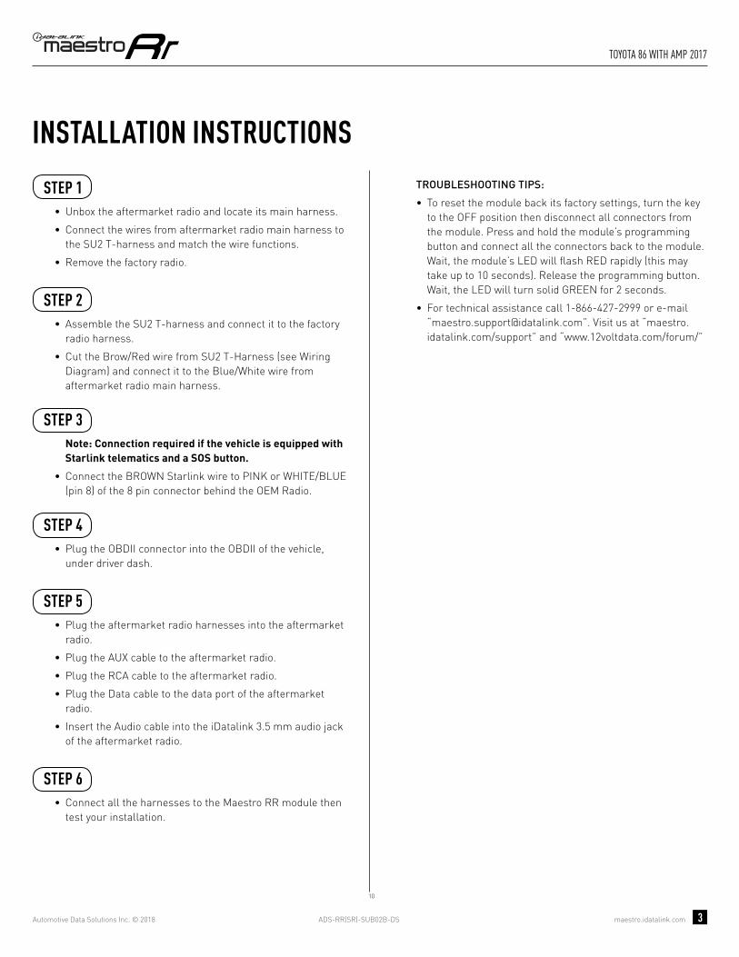
ADS-RR(SR)-SUB02B-DS maestro.idatalink.com
toyota 86 with amp 2017
Automotive Data Solutions Inc. © 2018 3
INSTALLATION INSTRUCTIONS STEP 1
• Unbox the aftermarket radio and locate its main harness.
• Connect the wires from aftermarket radio main harness to the SU2 T-harness and match the wire functions.
• Remove the factory radio.
STEP 2
• Assemble the SU2 T-harness and connect it to the factory radio harness.
• Cut the Brow/Red wire from SU2 T-Harness (see Wiring Diagram) and connect it to the Blue/White wire from aftermarket radio main harness.
STEP 3Note: Connection required if the vehicle is equipped with Starlink telematics and a SOS button.
• Connect the BROWN Starlink wire to PINK or WHITE/BLUE (pin 8) of the 8 pin connector behind the OEM Radio.
STEP 4• Plug the OBDII connector into the OBDII of the vehicle,
under driver dash.
STEP 5• Plug the aftermarket radio harnesses into the aftermarket
radio.
• Plug the AUX cable to the aftermarket radio.
• Plug the RCA cable to the aftermarket radio.
• Plug the Data cable to the data port of the aftermarket radio.
• Insert the Audio cable into the iDatalink 3.5 mm audio jack of the aftermarket radio.
STEP 6• Connect all the harnesses to the Maestro RR module then
test your installation.
TROUBLESHOOTING TIPS:
• To reset the module back its factory settings, turn the key to the OFF position then disconnect all connectors from the module. Press and hold the module’s programming button and connect all the connectors back to the module. Wait, the module’s LED will fl ash RED rapidly (this may take up to 10 seconds). Release the programming button. Wait, the LED will turn solid GREEN for 2 seconds.
• For technical assistance call 1-866-427-2999 or e-mail “[email protected]”. Visit us at “maestro.idatalink.com/support” and “www.12voltdata.com/forum/”
10

ADS-RR(SR)-SUB02B-DS maestro.idatalink.com
toyota 86 with amp 2017
Automotive Data Solutions Inc. © 2018 4
10
BACKUP CAMBACKUP CAMCC
AUXAUX
AA
D
BB
STARLINK PINK OR WHITE/BLUE - 08
8 PIN CONNECTOR BEHIND OEM RADIOSTEP 3
MAESTRO RR MODULE
STEP 1
SU2 T-HARNESS
STEP 5
STEP 6
WIRING DIAGRAM
WIRES FROMVEHICLE
FACTORY RADIO HARNESSSTEP 2
STEP 4 OBDII CONNECTOR
DATACABLE
AUDIOCABLE
CONNECT TOAFTERMARKET RADIO
BLUE
CONNECTIONS NOT REQUIRED
YELLOW
MAINHARNESS
YELLOW - 12V (+)
BLACK - GROUNDRED - ACCESSORY (+)
ORANGE - ILLUMINATION (+)PURPLE/WHITE - REVERSE LIGHT (+)LTGREEN - E-BRAKE (-)
BLUE - POWER ANTENNAPINK - VEHICLE SPEED
WHITEWHITE/BLACKGRAYGRAY/BLACKGREENGREEN/BLACK
PURPLE/BLACKPURPLE
LF RCA INPUT
RF RCA INPUT
LR RCA INPUT
RR RCA INPUT
RCA CABLES
GREENN.C.
CUT BROWN/REDWIRE (PIN 9)
CUT BROWN/REDWIRE (PIN 9)
BLUE/WHITE - AMP. TURN ON (+)
SEE RADIO WIREREFERENCECHARTFOR RADIO WIRECOLORS
BLUE/WHITEBLUE/WHITE

ADS-RR(SR)-SUB02B-DS maestro.idatalink.com
toyota 86 with amp 2017
Automotive Data Solutions Inc. © 2018 5
RADIO WIRE REFERENCE CHART
WireDescription Polarity Wire Color on Maestro
T-Harness Wire Color on Alpine cable Wire Color on Kenwood cable Wire Color on Pioneer cable
Illumination (+) Orange N/A Orange/White Orange/White
Reverse Light (+) Purple/White Orange/White Purple/White Purple/White
E-Brake (-) Lt Green Yellow/Blue Lt Green Lt Green
VSS (vehicle speed sensor) (DATA) Pink Green/White N/A Pink
Power Antenna (+) Blue Blue Blue N/A

PROGRAMMED FIRMWAREADS-RR(SR)-SUB02B-DS
PRODUCTS REQUIREDiDatalink Maestro RR Radio Replacement InterfaceiDatalink Maestro SU2 Installation Harness
OPTIONAL ACCESSORIES
ACC-uSU2
Click here for: Radar Integration Installation GuideRadar Integration Owner’s Guide for Kenwood and JVC Radios
E L E C T R O N I C S
INSTALL GUIDETOyOTA 86
WITh NAV
2017Retains steeRing wheel contRols, amplifieR and moRe!
NOTICE: Automotive Data Solutions Inc. (ADS) recommends having this installation performed by a certified technician. Logos and trademarks used here in are the properties of their respective owners.

ADS-RR(SR)-SUB02B-DS maestro.idatalink.com
toyota 86 with naV 2017
Automotive Data Solutions Inc. © 2018 2
WELCOME
NEED hELP?
Congratulations on the purchase of your iDatalink Maestro RR Radio replacement solution. You are now a few simple steps away from enjoying your new car radio with enhanced features. Before starting your installation, please ensure that your iDatalink Maestro module is programmed with the correct fi rmware and that you carefully review the Installation Diagram and Vehicle Wire Refer-ence Chart.
Please note that Maestro RR will only retain functionalities that were originally available in the vehicle.
1 866 427-2999
maestro.idatalink.com/supportwww.12voltdata.com/forum
TABLE OF CONTENTS
Installation Instructions 3
Wiring Diagram 4
Radio Wire Reference Chart 5

ADS-RR(SR)-SUB02B-DS maestro.idatalink.com
toyota 86 with naV 2017
Automotive Data Solutions Inc. © 2018 3
INSTALLATION INSTRUCTIONS STEP 1
• Unbox the aftermarket radio and locate its main harness.
• Cut the WHITE, GRAY, GREEN and PURPLE RCA tips.
• Connect the wires from aftermarket radio main harness to the SU2 T-harness and match the wire functions.
• Remove the factory radio.
STEP 2
• Assemble the SU2 T-harness and connect it to the factory radio harness.
STEP 3Note: Connection required if the vehicle is equipped with Starlink telematics and a SOS button.
• Connect the BROWN Starlink wire to PINK or WHITE/BLUE (pin 8) of the 8 pin connector behind the OEM Radio.
STEP 4• Plug the OBDII connector into the OBDII of the vehicle,
under driver dash.
STEP 5• Plug the aftermarket radio harnesses into the aftermarket
radio.
• Plug the AUX cable to the aftermarket radio.
• Plug the RCA cable to the aftermarket radio.
• Plug the Data cable to the data port of the aftermarket radio.
• Insert the Audio cable into the iDatalink 3.5 mm audio jack of the aftermarket radio.
STEP 6• Connect all the harnesses to the Maestro RR module then
test your installation.
TROUBLESHOOTING TIPS:
• To reset the module back its factory settings, turn the key to the OFF position then disconnect all connectors from the module. Press and hold the module’s programming button and connect all the connectors back to the module. Wait, the module’s LED will fl ash RED rapidly (this may take up to 10 seconds). Release the programming button. Wait, the LED will turn solid GREEN for 2 seconds.
• For technical assistance call 1-866-427-2999 or e-mail “[email protected]”. Visit us at “maestro.idatalink.com/support” and “www.12voltdata.com/forum/”
9

ADS-RR(SR)-SUB02B-DS maestro.idatalink.com
toyota 86 with naV 2017
Automotive Data Solutions Inc. © 2018 4
BB
9
BACKUP CAMBACKUP CAMCC
AUXAUX
AA
D
GREENN.C.
MAESTRO RR MODULE
CUT AND REMOVE THE RCA JACKS
STEP 1
MAINHARNESS
SU2 T-HARNESS
WHITE - LF SPEAKER (+)WHITE/BLACK - LF SPEAKER (-)GRAY - RF SPEAKER (+)GRAY/BLACK - RF SPEAKER (-)GREEN - LR SPEAKER (+)GREEN/BLACK - LR SPEAKER (-)
PURPLE/BLACK - RR SPEAKER (-)
YELLOW - 12V (+)
BLACK - GROUNDRED - ACCESSORY (+)
BLUE/WHITE - AMP. TURN ON (+)
PURPLE - RR SPEAKER (+)
STEP 5
STEP 6
ORANGE - ILLUMINATION (+)PURPLE/WHITE - REVERSE LIGHT (+)LTGREEN - E-BRAKE (-)
BLUE - POWER ANTENNA
STARLINK PINK OR WHITE/BLUE - 08
PINK - VEHICLE SPEED
WIRING DIAGRAM
WIRES FROMVEHICLE
FACTORY RADIO HARNESS
8 PIN CONNECTOR BEHIND OEM RADIO
STEP 2
STEP 4
STEP 3
OBDII CONNECTOR
SEE RADIO WIREREFERENCECHARTFOR RADIO WIRECOLORS
DATACABLE
AUDIOCABLE
CONNECT TOAFTERMARKET RADIO
CONNECTIONS NOT REQUIRED
BLUE
NC
NC
YELLOW

ADS-RR(SR)-SUB02B-DS maestro.idatalink.com
toyota 86 with naV 2017
Automotive Data Solutions Inc. © 2018 5
RADIO WIRE REFERENCE CHART
WireDescription Polarity Wire Color on Maestro
T-Harness Wire Color on Alpine cable Wire Color on Kenwood cable Wire Color on Pioneer cable
Illumination (+) Orange N/A Orange/White Orange/White
Reverse Light (+) Purple/White Orange/White Purple/White Purple/White
E-Brake (-) Lt Green Yellow/Blue Lt Green Lt Green
VSS (vehicle speed sensor) (DATA) Pink Green/White N/A Pink
Power Antenna (+) Blue Blue Blue N/A

PROGRAMMED FIRMWAREADS-RR(SR)-SUB02B-DS
PRODUCTS REQUIREDiDatalink Maestro RR Radio Replacement InterfaceiDatalink Maestro SU2 Installation Harness
OPTIONAL ACCESSORIES
ACC-uSU2
Click here for: Radar Integration Installation GuideRadar Integration Owner’s Guide for Kenwood and JVC Radios
E L E C T R O N I C S
INSTALL GUIDETOyOTA 86WITh NAV WITh AMP
2017Retains steeRing wheel contRols, amplifieR and moRe!
NOTICE: Automotive Data Solutions Inc. (ADS) recommends having this installation performed by a certified technician. Logos and trademarks used here in are the properties of their respective owners.

ADS-RR(SR)-SUB02B-DS maestro.idatalink.com
toyota 86 with naV with amp 2017
Automotive Data Solutions Inc. © 2018 2
WELCOME
NEED hELP?
Congratulations on the purchase of your iDatalink Maestro RR Radio replacement solution. You are now a few simple steps away from enjoying your new car radio with enhanced features. Before starting your installation, please ensure that your iDatalink Maestro module is programmed with the correct fi rmware and that you carefully review the Installation Diagram and Vehicle Wire Refer-ence Chart.
Please note that Maestro RR will only retain functionalities that were originally available in the vehicle.
1 866 427-2999
maestro.idatalink.com/supportwww.12voltdata.com/forum
TABLE OF CONTENTS
Installation Instructions 3
Wiring Diagram 4
Radio Wire Reference Chart 5

ADS-RR(SR)-SUB02B-DS maestro.idatalink.com
toyota 86 with naV with amp 2017
Automotive Data Solutions Inc. © 2018 3
INSTALLATION INSTRUCTIONS STEP 1
• Unbox the aftermarket radio and locate its main harness.
• Connect the wires from aftermarket radio main harness to the SU2 T-harness and match the wire functions.
• Remove the factory radio.
STEP 2
• Assemble the SU2 T-harness and connect it to the factory radio harness.
• Cut the Brow/Red wire from SU2 T-Harness (see Wiring Diagram) and connect it to the Blue/White wire from aftermarket radio main harness.
STEP 3Note: Connection required if the vehicle is equipped with Starlink telematics and a SOS button.
• Connect the BROWN Starlink wire to PINK or WHITE/BLUE (pin 8) of the 8 pin connector behind the OEM Radio.
STEP 4• Plug the OBDII connector into the OBDII of the vehicle,
under driver dash.
STEP 5• Plug the aftermarket radio harnesses into the aftermarket
radio.
• Plug the AUX cable to the aftermarket radio.
• Plug the RCA cable to the aftermarket radio.
• Plug the Data cable to the data port of the aftermarket radio.
• Insert the Audio cable into the iDatalink 3.5 mm audio jack of the aftermarket radio.
STEP 6• Connect all the harnesses to the Maestro RR module then
test your installation.
TROUBLESHOOTING TIPS:
• To reset the module back its factory settings, turn the key to the OFF position then disconnect all connectors from the module. Press and hold the module’s programming button and connect all the connectors back to the module. Wait, the module’s LED will fl ash RED rapidly (this may take up to 10 seconds). Release the programming button. Wait, the LED will turn solid GREEN for 2 seconds.
• For technical assistance call 1-866-427-2999 or e-mail “[email protected]”. Visit us at “maestro.idatalink.com/support” and “www.12voltdata.com/forum/”
11
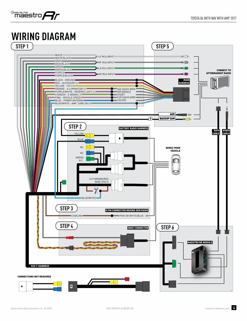
ADS-RR(SR)-SUB02B-DS maestro.idatalink.com
toyota 86 with naV with amp 2017
Automotive Data Solutions Inc. © 2018 4
11
BACKUP CAMBACKUP CAMCC
BB
AUXAUX
AA D
GREENN.C.
MAESTRO RR MODULE
STEP 1
SU2 T-HARNESS
STEP 5
STEP 6
STARLINK PINK OR WHITE/BLUE - 08
WIRING DIAGRAM
WIRES FROMVEHICLE
FACTORY RADIO HARNESS
8 PIN CONNECTOR BEHIND OEM RADIO
STEP 2
STEP 4
STEP 3
OBDII CONNECTOR
DATACABLE
AUDIOCABLE
CONNECT TOAFTERMARKET RADIO
CONNECTIONS NOT REQUIRED
BLUE
NC
NC
YELLOW
MAINHARNESS
YELLOW - 12V (+)
BLACK - GROUNDRED - ACCESSORY (+)
BLUE/WHITE - AMP. TURN ON (+)
ORANGE - ILLUMINATION (+)PURPLE/WHITE - REVERSE LIGHT (+)LTGREEN - E-BRAKE (-)
BLUE - POWER ANTENNAPINK - VEHICLE SPEED
SEE RADIO WIREREFERENCECHARTFOR RADIO WIRECOLORS
WHITEWHITE/BLACKGRAYGRAY/BLACKGREENGREEN/BLACK
PURPLE/BLACKPURPLE
LF RCA INPUT
RF RCA INPUT
LR RCA INPUT
RR RCA INPUT
BLUE/WHITEBLUE/WHITE
CUT BROWN/REDWIRE (PIN 9)
CUT BROWN/REDWIRE (PIN 9)
CUT BROWN/REDWIRE (PIN 9)

ADS-RR(SR)-SUB02B-DS maestro.idatalink.com
toyota 86 with naV with amp 2017
Automotive Data Solutions Inc. © 2018 5
RADIO WIRE REFERENCE CHART
WireDescription Polarity Wire Color on Maestro
T-Harness Wire Color on Alpine cable Wire Color on Kenwood cable Wire Color on Pioneer cable
Illumination (+) Orange N/A Orange/White Orange/White
Reverse Light (+) Purple/White Orange/White Purple/White Purple/White
E-Brake (-) Lt Green Yellow/Blue Lt Green Lt Green
VSS (vehicle speed sensor) (DATA) Pink Green/White N/A Pink
Power Antenna (+) Blue Blue Blue N/A