how to use this install guide - amazon...
TRANSCRIPT

NOTICE: Automotive Data Solutions Inc. (ADS) recommends having this installation performed by a certifi ed technician. Logos and trademarks used here in are the properties of their respective owners.
WARNINGPressing the printer icon or “quick printing” this document will print
all of the guides in this compilation.
Open the Bookmarks menu and find your vehicle OR scroll down until you find the install guide for your vehicle.
Print only the pages for your vehicle using the advanced options in the Print menu.
Install your Maestro RR according to the guide for your vehicle.
HOW TO USE THIS INSTALL GUIDE1
2
3
SELECT VEHICLE PRINT PAGES NEEDED

OPTIONAL ACCESSORIESADS-HRN(AV)-CHR01
PROGRAMMED FIRMWAREADS-RR(SR)-CHR01-AS
PRODUCTS REQUIREDiDatalink Maestro RR Radio Replacement InterfaceiDatalink Maestro CH1 Installation Harness
INSTALL GUIDEChRySLER 200
2011-2014retains steering wheel controls and more!
NOTICE: Automotive Data Solutions Inc. (ADS) recommends having this installation performed by a certified technician. Logos and trademarks used here in are the properties of their respective owners.
ADS-RR(SR)-CHR01-AS maestro.idatalink.com
chrysler 200 2011-2014
Automotive Data Solutions Inc. © 2017 2
WELCOME
NEED hELP?
Congratulations on the purchase of your iDatalink Maestro RR Radio replacement solution. You are now a few simple steps away from enjoying your new car radio with enhanced features. Before starting your installation, please ensure that your iDatalink Maestro module is programmed with the correct fi rmware for your vehicle as per the Getting Started section, and that you carefully review the Installation Diagram and Vehicle Wire Reference Chart.
Please note that Maestro RR will only retain functionalities that were originally available in the vehicle.
1 866 427-2999
maestro.idatalink.com/supportwww.12voltdata.com/forum
DURING INSTALLATION
Installation Instructions 3
Wiring Diagram 4

ADS-RR(SR)-CHR01-AS maestro.idatalink.com
chrysler 200 2011-2014
Automotive Data Solutions Inc. © 2017 3
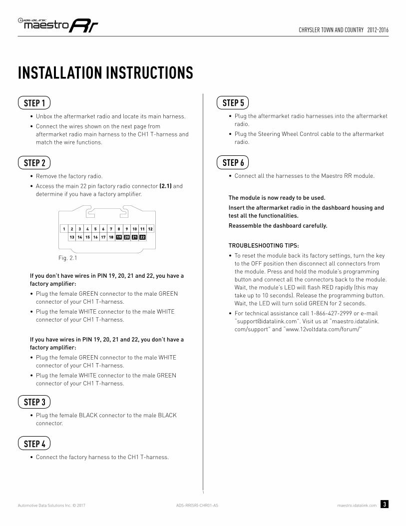
INSTALLATION INSTRUCTIONS STEP 1
• Unbox the aftermarket radio and locate its main harness.
• Connect the wires shown on the next page from aftermarket radio main harness to the CH1 T-harness and match the wire functions.
STEP 2
• Remove the factory radio.
• Access the main 22 pin factory radio connector (2.1) and determine if you have a factory amplifi er.
If you don’t have wires in PIN 19, 20, 21 and 22, you have a factory amplifi er:
• Plug the female GREEN connector to the male GREEN connector of your CH1 T-harness.
• Plug the female WHITE connector to the male WHITE connector of your CH1 T-harness.
If you have wires in PIN 19, 20, 21 and 22, you don’t have a factory amplifi er:
• Plug the female GREEN connector to the male WHITE connector of your CH1 T-harness.
• Plug the female WHITE connector to the male GREEN connector of your CH1 T-harness.
STEP 3• Plug the female RED connector to the male BLACK
connector.
STEP 4• Connect the factory harness to the CH1 T-harness.
STEP 5• Plug the aftermarket radio harnesses into the aftermarket
radio.
• Plug the Steering Wheel Control cable to the aftermarket radio.
STEP 6• Connect all the harnesses to the Maestro RR module.
The module is now ready to be used.
Insert the aftermarket radio in the dashboard housing and test all the functionalities.
Reassemble the dashboard carefully.
TROUBLESHOOTING TIPS:
• To reset the module back its factory settings, turn the key to the OFF position then disconnect all connectors from the module. Press and hold the module’s programming button and connect all the connectors back to the module. Wait, the module’s LED will fl ash RED rapidly (this may take up to 10 seconds). Release the programming button. Wait, the LED will turn solid GREEN for 2 seconds.
• For technical assistance call 1-866-427-2999 or e-mail “[email protected]”. Visit us at “maestro.idatalink.com/support” and “www.12voltdata.com/forum/”
87651 109
19181716
432
151413 21
11 12
2220
Fig. 2.1
2

ADS-RR(SR)-CHR01-AS maestro.idatalink.com
chrysler 200 2011-2014
Automotive Data Solutions Inc. © 2017 4
C
A FG
C
A
G
F
2
E
E
BROWN - MUTE (-)
WIRING DIAGRAMSTEP 1
STEP 2
STEP 3
STEP 4
STEP 5
STEP 6
MAESTRO RR MODULE
WHITE - LF SPEAKER (+)WHITE/BLACK - LF SPEAKER (-)GRAY - RF SPEAKER (+)GRAY/BLACK - RF SPEAKER (-)GREEN - LR SPEAKER (+)GREEN/BLACK - LR SPEAKER (-)
PURPLE/BLACK - RR SPEAKER (-)
YELLOW - 12V (+)
BLACK - GROUNDRED - ACCESSORY (+)
GREEN WHITE
WHITE GREEN
CONNECTIONS WITHOUT AMP
CONNECTIONS WITH AMP
ORANGE - ILLUMINATION (+)PURPLE/WHITE - REVERSE LIGHT (+)LTGREEN - E-BRAKE (-)
BLUE/WHITE - AMP. TURN ON (+)
MAINHARNESS
PURPLE - RR SPEAKER (+)
CONNECT TOAFTERMARKET RADIO
CH1 T-HARNESS
FACTORY RADIOHARNESS
RED/BROWN (NC)YELLOW/BROWN (NC)
WIRES FROMVEHICLE
PINK - VEHICLE SPEED (CONNECT IF THERE IS A MATCH)
GREEN GREEN
WHITEWHITE
BLACKRED
BLACK (NC)
STEERING WHEELCONTROL CABLE

OPTIONAL ACCESSORIESADS-HRN(AV)-CHR01
PROGRAMMED FIRMWAREADS-RR(SR)-CHR01-AS
PRODUCTS REQUIREDiDatalink Maestro RR Radio Replacement InterfaceiDatalink Maestro CH1 Installation Harness
INSTALL GUIDEChRySLER 300
2008-2010retains steering wheel controls and more!
NOTICE: Automotive Data Solutions Inc. (ADS) recommends having this installation performed by a certified technician. Logos and trademarks used here in are the properties of their respective owners.

ADS-RR(SR)-CHR01-AS maestro.idatalink.com
chrysler 300 2008-2010
Automotive Data Solutions Inc. © 2017 2
WELCOME
NEED hELP?
Congratulations on the purchase of your iDatalink Maestro RR Radio replacement solution. You are now a few simple steps away from enjoying your new car radio with enhanced features. Before starting your installation, please ensure that your iDatalink Maestro module is programmed with the correct fi rmware for your vehicle as per the Getting Started section, and that you carefully review the Installation Diagram and Vehicle Wire Reference Chart.
Please note that Maestro RR will only retain functionalities that were originally available in the vehicle.
1 866 427-2999
maestro.idatalink.com/supportwww.12voltdata.com/forum
DURING INSTALLATION
Installation Instructions 3
Wiring Diagram 4

ADS-RR(SR)-CHR01-AS maestro.idatalink.com
chrysler 300 2008-2010
Automotive Data Solutions Inc. © 2017 3
INSTALLATION INSTRUCTIONS STEP 1
• Unbox the aftermarket radio and locate its main harness.
• Connect the wires shown on the next page from aftermarket radio main harness to the CH1 T-harness and match the wire functions.
STEP 2
• Remove the factory radio.
• Access the main 22 pin factory radio connector (2.1) and determine if you have a factory amplifi er.
If you don’t have wires in PIN 19, 20, 21 and 22, you have a factory amplifi er:
• Plug the female GREEN connector to the male GREEN connector of your CH1 T-harness.
• Plug the female WHITE connector to the male WHITE connector of your CH1 T-harness.
If you have wires in PIN 19, 20, 21 and 22, you don’t have a factory amplifi er:
• Plug the female GREEN connector to the male WHITE connector of your CH1 T-harness.
• Plug the female WHITE connector to the male GREEN connector of your CH1 T-harness.
STEP 3• Plug the female RED connector to the male BLACK
connector.
STEP 4• Connect the factory harness to the CH1 T-harness.
STEP 5• Plug the aftermarket radio harnesses into the aftermarket
radio.
• Plug the Steering Wheel Control cable to the aftermarket radio.
STEP 6• Connect all the harnesses to the Maestro RR module.
The module is now ready to be used.
Insert the aftermarket radio in the dashboard housing and test all the functionalities.
Reassemble the dashboard carefully.
TROUBLESHOOTING TIPS:
• To reset the module back its factory settings, turn the key to the OFF position then disconnect all connectors from the module. Press and hold the module’s programming button and connect all the connectors back to the module. Wait, the module’s LED will fl ash RED rapidly (this may take up to 10 seconds). Release the programming button. Wait, the LED will turn solid GREEN for 2 seconds.
• For technical assistance call 1-866-427-2999 or e-mail “[email protected]”. Visit us at “maestro.idatalink.com/support” and “www.12voltdata.com/forum/”
87651 109
19181716
432
151413 21
11 12
2220
Fig. 2.1
2

ADS-RR(SR)-CHR01-AS maestro.idatalink.com
chrysler 300 2008-2010
Automotive Data Solutions Inc. © 2017 4
C
A FG
C
A
G
F
2
E
E
BROWN - MUTE (-)
WIRING DIAGRAMSTEP 1
STEP 2
STEP 3
STEP 4
STEP 5
STEP 6
MAESTRO RR MODULE
WHITE - LF SPEAKER (+)WHITE/BLACK - LF SPEAKER (-)GRAY - RF SPEAKER (+)GRAY/BLACK - RF SPEAKER (-)GREEN - LR SPEAKER (+)GREEN/BLACK - LR SPEAKER (-)
PURPLE/BLACK - RR SPEAKER (-)
YELLOW - 12V (+)
BLACK - GROUNDRED - ACCESSORY (+)
GREEN WHITE
WHITE GREEN
CONNECTIONS WITHOUT AMP
CONNECTIONS WITH AMP
ORANGE - ILLUMINATION (+)PURPLE/WHITE - REVERSE LIGHT (+)LTGREEN - E-BRAKE (-)
BLUE/WHITE - AMP. TURN ON (+)
MAINHARNESS
PURPLE - RR SPEAKER (+)
CONNECT TOAFTERMARKET RADIO
CH1 T-HARNESS
FACTORY RADIOHARNESS
RED/BROWN (NC)YELLOW/BROWN (NC)
WIRES FROMVEHICLE
PINK - VEHICLE SPEED (CONNECT IF THERE IS A MATCH)
GREEN GREEN
WHITEWHITE
BLACKRED
BLACK (NC)
STEERING WHEELCONTROL CABLE

OPTIONAL ACCESSORIESADS-HRN(AV)-CHR01
PROGRAMMED FIRMWAREADS-RR(SR)-CHR01-AS
PRODUCTS REQUIREDiDatalink Maestro RR Radio Replacement InterfaceiDatalink Maestro CH1 Installation Harness
INSTALL GUIDEChRySLER ASPEN
2008-2009retains steering wheel controls and more!
NOTICE: Automotive Data Solutions Inc. (ADS) recommends having this installation performed by a certified technician. Logos and trademarks used here in are the properties of their respective owners.

ADS-RR(SR)-CHR01-AS maestro.idatalink.com
chrysler aspen 2008-2009
Automotive Data Solutions Inc. © 2017 2
WELCOME
NEED hELP?
Congratulations on the purchase of your iDatalink Maestro RR Radio replacement solution. You are now a few simple steps away from enjoying your new car radio with enhanced features. Before starting your installation, please ensure that your iDatalink Maestro module is programmed with the correct fi rmware for your vehicle as per the Getting Started section, and that you carefully review the Installation Diagram and Vehicle Wire Reference Chart.
Please note that Maestro RR will only retain functionalities that were originally available in the vehicle.
1 866 427-2999
maestro.idatalink.com/supportwww.12voltdata.com/forum
DURING INSTALLATION
Installation Instructions 3
Wiring Diagram 4

ADS-RR(SR)-CHR01-AS maestro.idatalink.com
chrysler aspen 2008-2009
Automotive Data Solutions Inc. © 2017 3
INSTALLATION INSTRUCTIONS STEP 1
• Unbox the aftermarket radio and locate its main harness.
• Connect the wires shown on the next page from aftermarket radio main harness to the CH1 T-harness and match the wire functions.
STEP 2
• Remove the factory radio.
• Access the main 22 pin factory radio connector (2.1) and determine if you have a factory amplifi er.
If you don’t have wires in PIN 19, 20, 21 and 22, you have a factory amplifi er:
• Plug the female GREEN connector to the male GREEN connector of your CH1 T-harness.
• Plug the female WHITE connector to the male WHITE connector of your CH1 T-harness.
If you have wires in PIN 19, 20, 21 and 22, you don’t have a factory amplifi er:
• Plug the female GREEN connector to the male WHITE connector of your CH1 T-harness.
• Plug the female WHITE connector to the male GREEN connector of your CH1 T-harness.
STEP 3• Plug the female RED connector to the male BLACK
connector.
STEP 4• Connect the factory harness to the CH1 T-harness.
STEP 5• Plug the aftermarket radio harnesses into the aftermarket
radio.
• Plug the Steering Wheel Control cable to the aftermarket radio.
STEP 6• Connect all the harnesses to the Maestro RR module.
The module is now ready to be used.
Insert the aftermarket radio in the dashboard housing and test all the functionalities.
Reassemble the dashboard carefully.
TROUBLESHOOTING TIPS:
• To reset the module back its factory settings, turn the key to the OFF position then disconnect all connectors from the module. Press and hold the module’s programming button and connect all the connectors back to the module. Wait, the module’s LED will fl ash RED rapidly (this may take up to 10 seconds). Release the programming button. Wait, the LED will turn solid GREEN for 2 seconds.
• For technical assistance call 1-866-427-2999 or e-mail “[email protected]”. Visit us at “maestro.idatalink.com/support” and “www.12voltdata.com/forum/”
87651 109
19181716
432
151413 21
11 12
2220
Fig. 2.1
2

ADS-RR(SR)-CHR01-AS maestro.idatalink.com
chrysler aspen 2008-2009
Automotive Data Solutions Inc. © 2017 4
C
A FG
C
A
G
F
2
E
E
BROWN - MUTE (-)
WIRING DIAGRAMSTEP 1
STEP 2
STEP 3
STEP 4
STEP 5
STEP 6
MAESTRO RR MODULE
WHITE - LF SPEAKER (+)WHITE/BLACK - LF SPEAKER (-)GRAY - RF SPEAKER (+)GRAY/BLACK - RF SPEAKER (-)GREEN - LR SPEAKER (+)GREEN/BLACK - LR SPEAKER (-)
PURPLE/BLACK - RR SPEAKER (-)
YELLOW - 12V (+)
BLACK - GROUNDRED - ACCESSORY (+)
GREEN WHITE
WHITE GREEN
CONNECTIONS WITHOUT AMP
CONNECTIONS WITH AMP
ORANGE - ILLUMINATION (+)PURPLE/WHITE - REVERSE LIGHT (+)LTGREEN - E-BRAKE (-)
BLUE/WHITE - AMP. TURN ON (+)
MAINHARNESS
PURPLE - RR SPEAKER (+)
CONNECT TOAFTERMARKET RADIO
CH1 T-HARNESS
FACTORY RADIOHARNESS
RED/BROWN (NC)YELLOW/BROWN (NC)
WIRES FROMVEHICLE
PINK - VEHICLE SPEED (CONNECT IF THERE IS A MATCH)
GREEN GREEN
WHITEWHITE
BLACKRED
BLACK (NC)
STEERING WHEELCONTROL CABLE

OPTIONAL ACCESSORIESADS-HRN(AV)-CHR01
PROGRAMMED FIRMWAREADS-RR(SR)-CHR01-AS
PRODUCTS REQUIREDiDatalink Maestro RR Radio Replacement InterfaceiDatalink Maestro CH1 Installation Harness
INSTALL GUIDEChRySLER SEbRING
2007-2010retains steering wheel controls and more!
NOTICE: Automotive Data Solutions Inc. (ADS) recommends having this installation performed by a certified technician. Logos and trademarks used here in are the properties of their respective owners.

ADS-RR(SR)-CHR01-AS maestro.idatalink.com
chrysler sebring 2007-2010
Automotive Data Solutions Inc. © 2017 2
WELCOME
NEED hELP?
Congratulations on the purchase of your iDatalink Maestro RR Radio replacement solution. You are now a few simple steps away from enjoying your new car radio with enhanced features. Before starting your installation, please ensure that your iDatalink Maestro module is programmed with the correct fi rmware for your vehicle as per the Getting Started section, and that you carefully review the Installation Diagram and Vehicle Wire Reference Chart.
Please note that Maestro RR will only retain functionalities that were originally available in the vehicle.
1 866 427-2999
maestro.idatalink.com/supportwww.12voltdata.com/forum
DURING INSTALLATION
Installation Instructions 3
Wiring Diagram 4

ADS-RR(SR)-CHR01-AS maestro.idatalink.com
chrysler sebring 2007-2010
Automotive Data Solutions Inc. © 2017 3
INSTALLATION INSTRUCTIONS STEP 1
• Unbox the aftermarket radio and locate its main harness.
• Connect the wires shown on the next page from aftermarket radio main harness to the CH1 T-harness and match the wire functions.
STEP 2
• Remove the factory radio.
• Access the main 22 pin factory radio connector (2.1) and determine if you have a factory amplifi er.
If you don’t have wires in PIN 19, 20, 21 and 22, you have a factory amplifi er:
• Plug the female GREEN connector to the male GREEN connector of your CH1 T-harness.
• Plug the female WHITE connector to the male WHITE connector of your CH1 T-harness.
If you have wires in PIN 19, 20, 21 and 22, you don’t have a factory amplifi er:
• Plug the female GREEN connector to the male WHITE connector of your CH1 T-harness.
• Plug the female WHITE connector to the male GREEN connector of your CH1 T-harness.
STEP 3• Plug the female RED connector to the male BLACK
connector.
STEP 4• Connect the factory harness to the CH1 T-harness.
STEP 5• Plug the aftermarket radio harnesses into the aftermarket
radio.
• Plug the Steering Wheel Control cable to the aftermarket radio.
STEP 6• Connect all the harnesses to the Maestro RR module.
The module is now ready to be used.
Insert the aftermarket radio in the dashboard housing and test all the functionalities.
Reassemble the dashboard carefully.
TROUBLESHOOTING TIPS:
• To reset the module back its factory settings, turn the key to the OFF position then disconnect all connectors from the module. Press and hold the module’s programming button and connect all the connectors back to the module. Wait, the module’s LED will fl ash RED rapidly (this may take up to 10 seconds). Release the programming button. Wait, the LED will turn solid GREEN for 2 seconds.
• For technical assistance call 1-866-427-2999 or e-mail “[email protected]”. Visit us at “maestro.idatalink.com/support” and “www.12voltdata.com/forum/”
87651 109
19181716
432
151413 21
11 12
2220
Fig. 2.1
2

ADS-RR(SR)-CHR01-AS maestro.idatalink.com
chrysler sebring 2007-2010
Automotive Data Solutions Inc. © 2017 4
C
A FG
C
A
G
F
2
E
E
BROWN - MUTE (-)
WIRING DIAGRAMSTEP 1
STEP 2
STEP 3
STEP 4
STEP 5
STEP 6
MAESTRO RR MODULE
WHITE - LF SPEAKER (+)WHITE/BLACK - LF SPEAKER (-)GRAY - RF SPEAKER (+)GRAY/BLACK - RF SPEAKER (-)GREEN - LR SPEAKER (+)GREEN/BLACK - LR SPEAKER (-)
PURPLE/BLACK - RR SPEAKER (-)
YELLOW - 12V (+)
BLACK - GROUNDRED - ACCESSORY (+)
GREEN WHITE
WHITE GREEN
CONNECTIONS WITHOUT AMP
CONNECTIONS WITH AMP
ORANGE - ILLUMINATION (+)PURPLE/WHITE - REVERSE LIGHT (+)LTGREEN - E-BRAKE (-)
BLUE/WHITE - AMP. TURN ON (+)
MAINHARNESS
PURPLE - RR SPEAKER (+)
CONNECT TOAFTERMARKET RADIO
CH1 T-HARNESS
FACTORY RADIOHARNESS
RED/BROWN (NC)YELLOW/BROWN (NC)
WIRES FROMVEHICLE
PINK - VEHICLE SPEED (CONNECT IF THERE IS A MATCH)
GREEN GREEN
WHITEWHITE
BLACKRED
BLACK (NC)
STEERING WHEELCONTROL CABLE

OPTIONAL ACCESSORIESADS-HRN(AV)-CHR01
PROGRAMMED FIRMWAREADS-RR(SR)-CHR01-AS
PRODUCTS REQUIREDiDatalink Maestro RR Radio Replacement InterfaceiDatalink Maestro CH1 Installation Harness
INSTALL GUIDEChRySLER TOWN AND COUNTRy
2008-2011retains steering wheel controls and more!
NOTICE: Automotive Data Solutions Inc. (ADS) recommends having this installation performed by a certified technician. Logos and trademarks used here in are the properties of their respective owners.

ADS-RR(SR)-CHR01-AS maestro.idatalink.com
chrysler town and country 2008-2011
Automotive Data Solutions Inc. © 2017 2
WELCOME
NEED hELP?
Congratulations on the purchase of your iDatalink Maestro RR Radio replacement solution. You are now a few simple steps away from enjoying your new car radio with enhanced features. Before starting your installation, please ensure that your iDatalink Maestro module is programmed with the correct fi rmware for your vehicle as per the Getting Started section, and that you carefully review the Installation Diagram and Vehicle Wire Reference Chart.
Please note that Maestro RR will only retain functionalities that were originally available in the vehicle.
1 866 427-2999
maestro.idatalink.com/supportwww.12voltdata.com/forum
DURING INSTALLATION
Installation Instructions 3
Wiring Diagram 4

ADS-RR(SR)-CHR01-AS maestro.idatalink.com
chrysler town and country 2008-2011
Automotive Data Solutions Inc. © 2017 3
INSTALLATION INSTRUCTIONS STEP 1
• Unbox the aftermarket radio and locate its main harness.
• Connect the wires shown on the next page from aftermarket radio main harness to the CH1 T-harness and match the wire functions.
STEP 2
• Remove the factory radio.
• Access the main 22 pin factory radio connector (2.1) and determine if you have a factory amplifi er.
If you don’t have wires in PIN 19, 20, 21 and 22, you have a factory amplifi er:
• Plug the female GREEN connector to the male GREEN connector of your CH1 T-harness.
• Plug the female WHITE connector to the male WHITE connector of your CH1 T-harness.
If you have wires in PIN 19, 20, 21 and 22, you don’t have a factory amplifi er:
• Plug the female GREEN connector to the male WHITE connector of your CH1 T-harness.
• Plug the female WHITE connector to the male GREEN connector of your CH1 T-harness.
STEP 3• Plug the female BLACK connector to the male BLACK
connector.
STEP 4• Connect the factory harness to the CH1 T-harness.
STEP 5• Plug the aftermarket radio harnesses into the aftermarket
radio.
• Plug the Steering Wheel Control cable to the aftermarket radio.
STEP 6• Connect all the harnesses to the Maestro RR module.
The module is now ready to be used.
Insert the aftermarket radio in the dashboard housing and test all the functionalities.
Reassemble the dashboard carefully.
TROUBLESHOOTING TIPS:
• To reset the module back its factory settings, turn the key to the OFF position then disconnect all connectors from the module. Press and hold the module’s programming button and connect all the connectors back to the module. Wait, the module’s LED will fl ash RED rapidly (this may take up to 10 seconds). Release the programming button. Wait, the LED will turn solid GREEN for 2 seconds.
• For technical assistance call 1-866-427-2999 or e-mail “[email protected]”. Visit us at “maestro.idatalink.com/support” and “www.12voltdata.com/forum/”
87651 109
19181716
432
151413 21
11 12
2220
Fig. 2.1
1

ADS-RR(SR)-CHR01-AS maestro.idatalink.com
chrysler town and country 2008-2011
Automotive Data Solutions Inc. © 2017 4
C
A FG
C
A
G
F
1
E
E
WIRING DIAGRAMSTEP 1
STEP 2
STEP 3
STEP 4
STEP 5
STEP 6
MAESTRO RR MODULE
WHITE - LF SPEAKER (+)WHITE/BLACK - LF SPEAKER (-)GRAY - RF SPEAKER (+)GRAY/BLACK - RF SPEAKER (-)GREEN - LR SPEAKER (+)GREEN/BLACK - LR SPEAKER (-)
PURPLE/BLACK - RR SPEAKER (-)
YELLOW - 12V (+)
BLACK - GROUNDRED - ACCESSORY (+)
GREEN WHITE
WHITE GREEN
CONNECTIONS WITHOUT AMP
CONNECTIONS WITH AMP
ORANGE - ILLUMINATION (+)PURPLE/WHITE - REVERSE LIGHT (+) (*1)LTGREEN - E-BRAKE (-)
BLUE/WHITE - AMP. TURN ON (+)
MAINHARNESS
PURPLE - RR SPEAKER (+)
CONNECT TOAFTERMARKET RADIO
CH1 T-HARNESS
FACTORY RADIOHARNESS
RED/BROWN (NC)YELLOW/BROWN (NC)
WIRES FROMVEHICLE
PINK - VEHICLE SPEED (CONNECT IF THERE IS A MATCH)
GREEN GREEN
WHITEWHITE
BLACKBLACK
STEERING WHEELCONTROL CABLE
RED (NC)
BROWN - MUTE (-)

OPTIONAL ACCESSORIESADS-HRN(AV)-CHR01
PROGRAMMED FIRMWAREADS-RR(SR)-CHR01-AS
PRODUCTS REQUIREDiDatalink Maestro RR Radio Replacement InterfaceiDatalink Maestro CH1 Installation Harness
INSTALL GUIDEChRySLER TOWN AND COUNTRy
2012-2016retains steering wheel controls and more!
NOTICE: Automotive Data Solutions Inc. (ADS) recommends having this installation performed by a certified technician. Logos and trademarks used here in are the properties of their respective owners.

ADS-RR(SR)-CHR01-AS maestro.idatalink.com
chrysler town and country 2012-2016
Automotive Data Solutions Inc. © 2017 2
WELCOME
NEED hELP?
Congratulations on the purchase of your iDatalink Maestro RR Radio replacement solution. You are now a few simple steps away from enjoying your new car radio with enhanced features. Before starting your installation, please ensure that your iDatalink Maestro module is programmed with the correct fi rmware for your vehicle as per the Getting Started section, and that you carefully review the Installation Diagram and Vehicle Wire Reference Chart.
Please note that Maestro RR will only retain functionalities that were originally available in the vehicle.
1 866 427-2999
maestro.idatalink.com/supportwww.12voltdata.com/forum
DURING INSTALLATION
Installation Instructions 3
Wiring Diagram 4
ADS-RR(SR)-CHR01-AS maestro.idatalink.com
chrysler town and country 2012-2016
Automotive Data Solutions Inc. © 2017 3
INSTALLATION INSTRUCTIONS STEP 1
• Unbox the aftermarket radio and locate its main harness.
• Connect the wires shown on the next page from aftermarket radio main harness to the CH1 T-harness and match the wire functions.
STEP 2
• Remove the factory radio.
• Access the main 22 pin factory radio connector (2.1) and determine if you have a factory amplifi er.
If you don’t have wires in PIN 19, 20, 21 and 22, you have a factory amplifi er:
• Plug the female GREEN connector to the male GREEN connector of your CH1 T-harness.
• Plug the female WHITE connector to the male WHITE connector of your CH1 T-harness.
If you have wires in PIN 19, 20, 21 and 22, you don’t have a factory amplifi er:
• Plug the female GREEN connector to the male WHITE connector of your CH1 T-harness.
• Plug the female WHITE connector to the male GREEN connector of your CH1 T-harness.
STEP 3• Plug the female BLACK connector to the male BLACK
connector.
STEP 4• Connect the factory harness to the CH1 T-harness.
STEP 5• Plug the aftermarket radio harnesses into the aftermarket
radio.
• Plug the Steering Wheel Control cable to the aftermarket radio.
STEP 6• Connect all the harnesses to the Maestro RR module.
The module is now ready to be used.
Insert the aftermarket radio in the dashboard housing and test all the functionalities.
Reassemble the dashboard carefully.
TROUBLESHOOTING TIPS:
• To reset the module back its factory settings, turn the key to the OFF position then disconnect all connectors from the module. Press and hold the module’s programming button and connect all the connectors back to the module. Wait, the module’s LED will fl ash RED rapidly (this may take up to 10 seconds). Release the programming button. Wait, the LED will turn solid GREEN for 2 seconds.
• For technical assistance call 1-866-427-2999 or e-mail “[email protected]”. Visit us at “maestro.idatalink.com/support” and “www.12voltdata.com/forum/”
87651 109
19181716
432
151413 21
11 12
2220
Fig. 2.1
1

ADS-RR(SR)-CHR01-AS maestro.idatalink.com
chrysler town and country 2012-2016
Automotive Data Solutions Inc. © 2017 4
C
A FG
C
A
G
F
1
E
E
WIRING DIAGRAMSTEP 1
STEP 2
STEP 3
STEP 4
STEP 5
STEP 6
MAESTRO RR MODULE
WHITE - LF SPEAKER (+)WHITE/BLACK - LF SPEAKER (-)GRAY - RF SPEAKER (+)GRAY/BLACK - RF SPEAKER (-)GREEN - LR SPEAKER (+)GREEN/BLACK - LR SPEAKER (-)
PURPLE/BLACK - RR SPEAKER (-)
YELLOW - 12V (+)
BLACK - GROUNDRED - ACCESSORY (+)
GREEN WHITE
WHITE GREEN
CONNECTIONS WITHOUT AMP
CONNECTIONS WITH AMP
ORANGE - ILLUMINATION (+)PURPLE/WHITE - REVERSE LIGHT (+) (*1)LTGREEN - E-BRAKE (-)
BLUE/WHITE - AMP. TURN ON (+)
MAINHARNESS
PURPLE - RR SPEAKER (+)
CONNECT TOAFTERMARKET RADIO
CH1 T-HARNESS
FACTORY RADIOHARNESS
RED/BROWN (NC)YELLOW/BROWN (NC)
WIRES FROMVEHICLE
PINK - VEHICLE SPEED (CONNECT IF THERE IS A MATCH)
GREEN GREEN
WHITEWHITE
BLACKBLACK
STEERING WHEELCONTROL CABLE
RED (NC)
BROWN - MUTE (-)

OPTIONAL ACCESSORIESADS-HRN(AV)-CHR01
PROGRAMMED FIRMWAREADS-RR(SR)-CHR01-AS
PRODUCTS REQUIREDiDatalink Maestro RR Radio Replacement InterfaceiDatalink Maestro CH1 Installation Harness
INSTALL GUIDEDODGE AvENGER
2008-2014retains steering wheel controls and more!
NOTICE: Automotive Data Solutions Inc. (ADS) recommends having this installation performed by a certified technician. Logos and trademarks used here in are the properties of their respective owners.

ADS-RR(SR)-CHR01-AS maestro.idatalink.com
dodge avenger 2008-2014
Automotive Data Solutions Inc. © 2017 2
WELCOME
NEED hELP?
Congratulations on the purchase of your iDatalink Maestro RR Radio replacement solution. You are now a few simple steps away from enjoying your new car radio with enhanced features. Before starting your installation, please ensure that your iDatalink Maestro module is programmed with the correct fi rmware for your vehicle as per the Getting Started section, and that you carefully review the Installation Diagram and Vehicle Wire Reference Chart.
Please note that Maestro RR will only retain functionalities that were originally available in the vehicle.
1 866 427-2999
maestro.idatalink.com/supportwww.12voltdata.com/forum
DURING INSTALLATION
Installation Instructions 3
Wiring Diagram 4

ADS-RR(SR)-CHR01-AS maestro.idatalink.com
dodge avenger 2008-2014
Automotive Data Solutions Inc. © 2017 3
INSTALLATION INSTRUCTIONS STEP 1
• Unbox the aftermarket radio and locate its main harness.
• Connect the wires shown on the next page from aftermarket radio main harness to the CH1 T-harness and match the wire functions.
STEP 2
• Remove the factory radio.
• Access the main 22 pin factory radio connector (2.1) and determine if you have a factory amplifi er.
If you don’t have wires in PIN 19, 20, 21 and 22, you have a factory amplifi er:
• Plug the female GREEN connector to the male GREEN connector of your CH1 T-harness.
• Plug the female WHITE connector to the male WHITE connector of your CH1 T-harness.
If you have wires in PIN 19, 20, 21 and 22, you don’t have a factory amplifi er:
• Plug the female GREEN connector to the male WHITE connector of your CH1 T-harness.
• Plug the female WHITE connector to the male GREEN connector of your CH1 T-harness.
STEP 3• Plug the female RED connector to the male BLACK
connector.
STEP 4• Connect the factory harness to the CH1 T-harness.
STEP 5• Plug the aftermarket radio harnesses into the aftermarket
radio.
• Plug the Steering Wheel Control cable to the aftermarket radio.
STEP 6• Connect all the harnesses to the Maestro RR module.
The module is now ready to be used.
Insert the aftermarket radio in the dashboard housing and test all the functionalities.
Reassemble the dashboard carefully.
TROUBLESHOOTING TIPS:
• To reset the module back its factory settings, turn the key to the OFF position then disconnect all connectors from the module. Press and hold the module’s programming button and connect all the connectors back to the module. Wait, the module’s LED will fl ash RED rapidly (this may take up to 10 seconds). Release the programming button. Wait, the LED will turn solid GREEN for 2 seconds.
• For technical assistance call 1-866-427-2999 or e-mail “[email protected]”. Visit us at “maestro.idatalink.com/support” and “www.12voltdata.com/forum/”
87651 109
19181716
432
151413 21
11 12
2220
Fig. 2.1
2

ADS-RR(SR)-CHR01-AS maestro.idatalink.com
dodge avenger 2008-2014
Automotive Data Solutions Inc. © 2017 4
C
A FG
C
A
G
F
2
E
E
BROWN - MUTE (-)
WIRING DIAGRAMSTEP 1
STEP 2
STEP 3
STEP 4
STEP 5
STEP 6
MAESTRO RR MODULE
WHITE - LF SPEAKER (+)WHITE/BLACK - LF SPEAKER (-)GRAY - RF SPEAKER (+)GRAY/BLACK - RF SPEAKER (-)GREEN - LR SPEAKER (+)GREEN/BLACK - LR SPEAKER (-)
PURPLE/BLACK - RR SPEAKER (-)
YELLOW - 12V (+)
BLACK - GROUNDRED - ACCESSORY (+)
GREEN WHITE
WHITE GREEN
CONNECTIONS WITHOUT AMP
CONNECTIONS WITH AMP
ORANGE - ILLUMINATION (+)PURPLE/WHITE - REVERSE LIGHT (+)LTGREEN - E-BRAKE (-)
BLUE/WHITE - AMP. TURN ON (+)
MAINHARNESS
PURPLE - RR SPEAKER (+)
CONNECT TOAFTERMARKET RADIO
CH1 T-HARNESS
FACTORY RADIOHARNESS
RED/BROWN (NC)YELLOW/BROWN (NC)
WIRES FROMVEHICLE
PINK - VEHICLE SPEED (CONNECT IF THERE IS A MATCH)
GREEN GREEN
WHITEWHITE
BLACKRED
BLACK (NC)
STEERING WHEELCONTROL CABLE

OPTIONAL ACCESSORIESADS-HRN(AV)-CHR01
PROGRAMMED FIRMWAREADS-RR(SR)-CHR01-AS
PRODUCTS REQUIREDiDatalink Maestro RR Radio Replacement InterfaceiDatalink Maestro CH1 Installation Harness
INSTALL GUIDEDODGE CALIbER
2009-2012retains steering wheel controls and more!
NOTICE: Automotive Data Solutions Inc. (ADS) recommends having this installation performed by a certified technician. Logos and trademarks used here in are the properties of their respective owners.

ADS-RR(SR)-CHR01-AS maestro.idatalink.com
dodge caliber 2009-2012
Automotive Data Solutions Inc. © 2017 2
WELCOME
NEED hELP?
Congratulations on the purchase of your iDatalink Maestro RR Radio replacement solution. You are now a few simple steps away from enjoying your new car radio with enhanced features. Before starting your installation, please ensure that your iDatalink Maestro module is programmed with the correct fi rmware for your vehicle as per the Getting Started section, and that you carefully review the Installation Diagram and Vehicle Wire Reference Chart.
Please note that Maestro RR will only retain functionalities that were originally available in the vehicle.
1 866 427-2999
maestro.idatalink.com/supportwww.12voltdata.com/forum
DURING INSTALLATION
Installation Instructions 3
Wiring Diagram 4

ADS-RR(SR)-CHR01-AS maestro.idatalink.com
dodge caliber 2009-2012
Automotive Data Solutions Inc. © 2017 3
INSTALLATION INSTRUCTIONS STEP 1
• Unbox the aftermarket radio and locate its main harness.
• Connect the wires shown on the next page from aftermarket radio main harness to the CH1 T-harness and match the wire functions.
STEP 2
• Remove the factory radio.
• Access the main 22 pin factory radio connector (2.1) and determine if you have a factory amplifi er.
If you don’t have wires in PIN 19, 20, 21 and 22, you have a factory amplifi er:
• Plug the female GREEN connector to the male GREEN connector of your CH1 T-harness.
• Plug the female WHITE connector to the male WHITE connector of your CH1 T-harness.
If you have wires in PIN 19, 20, 21 and 22, you don’t have a factory amplifi er:
• Plug the female GREEN connector to the male WHITE connector of your CH1 T-harness.
• Plug the female WHITE connector to the male GREEN connector of your CH1 T-harness.
STEP 3• Plug the female RED connector to the male BLACK
connector.
STEP 4• Connect the factory harness to the CH1 T-harness.
STEP 5• Plug the aftermarket radio harnesses into the aftermarket
radio.
• Plug the Steering Wheel Control cable to the aftermarket radio.
STEP 6• Connect all the harnesses to the Maestro RR module.
The module is now ready to be used.
Insert the aftermarket radio in the dashboard housing and test all the functionalities.
Reassemble the dashboard carefully.
TROUBLESHOOTING TIPS:
• To reset the module back its factory settings, turn the key to the OFF position then disconnect all connectors from the module. Press and hold the module’s programming button and connect all the connectors back to the module. Wait, the module’s LED will fl ash RED rapidly (this may take up to 10 seconds). Release the programming button. Wait, the LED will turn solid GREEN for 2 seconds.
• For technical assistance call 1-866-427-2999 or e-mail “[email protected]”. Visit us at “maestro.idatalink.com/support” and “www.12voltdata.com/forum/”
87651 109
19181716
432
151413 21
11 12
2220
Fig. 2.1
2

ADS-RR(SR)-CHR01-AS maestro.idatalink.com
dodge caliber 2009-2012
Automotive Data Solutions Inc. © 2017 4
C
A FG
C
A
G
F
2
E
E
BROWN - MUTE (-)
WIRING DIAGRAMSTEP 1
STEP 2
STEP 3
STEP 4
STEP 5
STEP 6
MAESTRO RR MODULE
WHITE - LF SPEAKER (+)WHITE/BLACK - LF SPEAKER (-)GRAY - RF SPEAKER (+)GRAY/BLACK - RF SPEAKER (-)GREEN - LR SPEAKER (+)GREEN/BLACK - LR SPEAKER (-)
PURPLE/BLACK - RR SPEAKER (-)
YELLOW - 12V (+)
BLACK - GROUNDRED - ACCESSORY (+)
GREEN WHITE
WHITE GREEN
CONNECTIONS WITHOUT AMP
CONNECTIONS WITH AMP
ORANGE - ILLUMINATION (+)PURPLE/WHITE - REVERSE LIGHT (+)LTGREEN - E-BRAKE (-)
BLUE/WHITE - AMP. TURN ON (+)
MAINHARNESS
PURPLE - RR SPEAKER (+)
CONNECT TOAFTERMARKET RADIO
CH1 T-HARNESS
FACTORY RADIOHARNESS
RED/BROWN (NC)YELLOW/BROWN (NC)
WIRES FROMVEHICLE
PINK - VEHICLE SPEED (CONNECT IF THERE IS A MATCH)
GREEN GREEN
WHITEWHITE
BLACKRED
BLACK (NC)
STEERING WHEELCONTROL CABLE

OPTIONAL ACCESSORIESADS-HRN(AV)-CHR01
PROGRAMMED FIRMWAREADS-RR(SR)-CHR01-AS
PRODUCTS REQUIREDiDatalink Maestro RR Radio Replacement InterfaceiDatalink Maestro CH1 Installation Harness
INSTALL GUIDEDODGE ChALLENGER
2008-2014retains steering wheel controls and more!
NOTICE: Automotive Data Solutions Inc. (ADS) recommends having this installation performed by a certified technician. Logos and trademarks used here in are the properties of their respective owners.

ADS-RR(SR)-CHR01-AS maestro.idatalink.com
dodge challenger 2008-2014
Automotive Data Solutions Inc. © 2017 2
WELCOME
NEED hELP?
Congratulations on the purchase of your iDatalink Maestro RR Radio replacement solution. You are now a few simple steps away from enjoying your new car radio with enhanced features. Before starting your installation, please ensure that your iDatalink Maestro module is programmed with the correct fi rmware for your vehicle as per the Getting Started section, and that you carefully review the Installation Diagram and Vehicle Wire Reference Chart.
Please note that Maestro RR will only retain functionalities that were originally available in the vehicle.
1 866 427-2999
maestro.idatalink.com/supportwww.12voltdata.com/forum
DURING INSTALLATION
Installation Instructions 3
Wiring Diagram 4

ADS-RR(SR)-CHR01-AS maestro.idatalink.com
dodge challenger 2008-2014
Automotive Data Solutions Inc. © 2017 3
INSTALLATION INSTRUCTIONS STEP 1
• Unbox the aftermarket radio and locate its main harness.
• Connect the wires shown on the next page from aftermarket radio main harness to the CH1 T-harness and match the wire functions.
STEP 2
• Remove the factory radio.
• Access the main 22 pin factory radio connector (2.1) and determine if you have a factory amplifi er.
If you don’t have wires in PIN 19, 20, 21 and 22, you have a factory amplifi er:
• Plug the female GREEN connector to the male GREEN connector of your CH1 T-harness.
• Plug the female WHITE connector to the male WHITE connector of your CH1 T-harness.
If you have wires in PIN 19, 20, 21 and 22, you don’t have a factory amplifi er:
• Plug the female GREEN connector to the male WHITE connector of your CH1 T-harness.
• Plug the female WHITE connector to the male GREEN connector of your CH1 T-harness.
STEP 3• Plug the female RED connector to the male BLACK
connector.
STEP 4• Connect the factory harness to the CH1 T-harness.
STEP 5• Plug the aftermarket radio harnesses into the aftermarket
radio.
• Plug the Steering Wheel Control cable to the aftermarket radio.
STEP 6• Connect all the harnesses to the Maestro RR module.
The module is now ready to be used.
Insert the aftermarket radio in the dashboard housing and test all the functionalities.
Reassemble the dashboard carefully.
TROUBLESHOOTING TIPS:
• To reset the module back its factory settings, turn the key to the OFF position then disconnect all connectors from the module. Press and hold the module’s programming button and connect all the connectors back to the module. Wait, the module’s LED will fl ash RED rapidly (this may take up to 10 seconds). Release the programming button. Wait, the LED will turn solid GREEN for 2 seconds.
• For technical assistance call 1-866-427-2999 or e-mail “[email protected]”. Visit us at “maestro.idatalink.com/support” and “www.12voltdata.com/forum/”
87651 109
19181716
432
151413 21
11 12
2220
Fig. 2.1
2

ADS-RR(SR)-CHR01-AS maestro.idatalink.com
dodge challenger 2008-2014
Automotive Data Solutions Inc. © 2017 4
C
A FG
C
A
G
F
2
E
E
BROWN - MUTE (-)
WIRING DIAGRAMSTEP 1
STEP 2
STEP 3
STEP 4
STEP 5
STEP 6
MAESTRO RR MODULE
WHITE - LF SPEAKER (+)WHITE/BLACK - LF SPEAKER (-)GRAY - RF SPEAKER (+)GRAY/BLACK - RF SPEAKER (-)GREEN - LR SPEAKER (+)GREEN/BLACK - LR SPEAKER (-)
PURPLE/BLACK - RR SPEAKER (-)
YELLOW - 12V (+)
BLACK - GROUNDRED - ACCESSORY (+)
GREEN WHITE
WHITE GREEN
CONNECTIONS WITHOUT AMP
CONNECTIONS WITH AMP
ORANGE - ILLUMINATION (+)PURPLE/WHITE - REVERSE LIGHT (+)LTGREEN - E-BRAKE (-)
BLUE/WHITE - AMP. TURN ON (+)
MAINHARNESS
PURPLE - RR SPEAKER (+)
CONNECT TOAFTERMARKET RADIO
CH1 T-HARNESS
FACTORY RADIOHARNESS
RED/BROWN (NC)YELLOW/BROWN (NC)
WIRES FROMVEHICLE
PINK - VEHICLE SPEED (CONNECT IF THERE IS A MATCH)
GREEN GREEN
WHITEWHITE
BLACKRED
BLACK (NC)
STEERING WHEELCONTROL CABLE

OPTIONAL ACCESSORIESADS-HRN(AV)-CHR01
PROGRAMMED FIRMWAREADS-RR(SR)-CHR01-AS
PRODUCTS REQUIREDiDatalink Maestro RR Radio Replacement InterfaceiDatalink Maestro CH1 Installation Harness
INSTALL GUIDEDODGE ChARGER
2008-2010retains steering wheel controls and more!
NOTICE: Automotive Data Solutions Inc. (ADS) recommends having this installation performed by a certified technician. Logos and trademarks used here in are the properties of their respective owners.

ADS-RR(SR)-CHR01-AS maestro.idatalink.com
dodge charger 2008-2010
Automotive Data Solutions Inc. © 2017 2
WELCOME
NEED hELP?
Congratulations on the purchase of your iDatalink Maestro RR Radio replacement solution. You are now a few simple steps away from enjoying your new car radio with enhanced features. Before starting your installation, please ensure that your iDatalink Maestro module is programmed with the correct fi rmware for your vehicle as per the Getting Started section, and that you carefully review the Installation Diagram and Vehicle Wire Reference Chart.
Please note that Maestro RR will only retain functionalities that were originally available in the vehicle.
1 866 427-2999
maestro.idatalink.com/supportwww.12voltdata.com/forum
DURING INSTALLATION
Installation Instructions 3
Wiring Diagram 4

ADS-RR(SR)-CHR01-AS maestro.idatalink.com
dodge charger 2008-2010
Automotive Data Solutions Inc. © 2017 3
INSTALLATION INSTRUCTIONS STEP 1
• Unbox the aftermarket radio and locate its main harness.
• Connect the wires shown on the next page from aftermarket radio main harness to the CH1 T-harness and match the wire functions.
STEP 2
• Remove the factory radio.
• Access the main 22 pin factory radio connector (2.1) and determine if you have a factory amplifi er.
If you don’t have wires in PIN 19, 20, 21 and 22, you have a factory amplifi er:
• Plug the female GREEN connector to the male GREEN connector of your CH1 T-harness.
• Plug the female WHITE connector to the male WHITE connector of your CH1 T-harness.
If you have wires in PIN 19, 20, 21 and 22, you don’t have a factory amplifi er:
• Plug the female GREEN connector to the male WHITE connector of your CH1 T-harness.
• Plug the female WHITE connector to the male GREEN connector of your CH1 T-harness.
STEP 3• Plug the female RED connector to the male BLACK
connector.
STEP 4• Connect the factory harness to the CH1 T-harness.
STEP 5• Plug the aftermarket radio harnesses into the aftermarket
radio.
• Plug the Steering Wheel Control cable to the aftermarket radio.
STEP 6• Connect all the harnesses to the Maestro RR module.
The module is now ready to be used.
Insert the aftermarket radio in the dashboard housing and test all the functionalities.
Reassemble the dashboard carefully.
TROUBLESHOOTING TIPS:
• To reset the module back its factory settings, turn the key to the OFF position then disconnect all connectors from the module. Press and hold the module’s programming button and connect all the connectors back to the module. Wait, the module’s LED will fl ash RED rapidly (this may take up to 10 seconds). Release the programming button. Wait, the LED will turn solid GREEN for 2 seconds.
• For technical assistance call 1-866-427-2999 or e-mail “[email protected]”. Visit us at “maestro.idatalink.com/support” and “www.12voltdata.com/forum/”
87651 109
19181716
432
151413 21
11 12
2220
Fig. 2.1
2

ADS-RR(SR)-CHR01-AS maestro.idatalink.com
dodge charger 2008-2010
Automotive Data Solutions Inc. © 2017 4
C
A FG
C
A
G
F
2
E
E
BROWN - MUTE (-)
WIRING DIAGRAMSTEP 1
STEP 2
STEP 3
STEP 4
STEP 5
STEP 6
MAESTRO RR MODULE
WHITE - LF SPEAKER (+)WHITE/BLACK - LF SPEAKER (-)GRAY - RF SPEAKER (+)GRAY/BLACK - RF SPEAKER (-)GREEN - LR SPEAKER (+)GREEN/BLACK - LR SPEAKER (-)
PURPLE/BLACK - RR SPEAKER (-)
YELLOW - 12V (+)
BLACK - GROUNDRED - ACCESSORY (+)
GREEN WHITE
WHITE GREEN
CONNECTIONS WITHOUT AMP
CONNECTIONS WITH AMP
ORANGE - ILLUMINATION (+)PURPLE/WHITE - REVERSE LIGHT (+)LTGREEN - E-BRAKE (-)
BLUE/WHITE - AMP. TURN ON (+)
MAINHARNESS
PURPLE - RR SPEAKER (+)
CONNECT TOAFTERMARKET RADIO
CH1 T-HARNESS
FACTORY RADIOHARNESS
RED/BROWN (NC)YELLOW/BROWN (NC)
WIRES FROMVEHICLE
PINK - VEHICLE SPEED (CONNECT IF THERE IS A MATCH)
GREEN GREEN
WHITEWHITE
BLACKRED
BLACK (NC)
STEERING WHEELCONTROL CABLE

OPTIONAL ACCESSORIESADS-HRN(AV)-CHR01
PROGRAMMED FIRMWAREADS-RR(SR)-CHR01-AS
PRODUCTS REQUIREDiDatalink Maestro RR Radio Replacement InterfaceiDatalink Maestro CH1 Installation Harness
INSTALL GUIDEDODGE DAkOTA
2008-2010retains steering wheel controls and more!
NOTICE: Automotive Data Solutions Inc. (ADS) recommends having this installation performed by a certified technician. Logos and trademarks used here in are the properties of their respective owners.

ADS-RR(SR)-CHR01-AS maestro.idatalink.com
dodge dakota 2008-2010
Automotive Data Solutions Inc. © 2017 2
WELCOME
NEED hELP?
Congratulations on the purchase of your iDatalink Maestro RR Radio replacement solution. You are now a few simple steps away from enjoying your new car radio with enhanced features. Before starting your installation, please ensure that your iDatalink Maestro module is programmed with the correct fi rmware for your vehicle as per the Getting Started section, and that you carefully review the Installation Diagram and Vehicle Wire Reference Chart.
Please note that Maestro RR will only retain functionalities that were originally available in the vehicle.
1 866 427-2999
maestro.idatalink.com/supportwww.12voltdata.com/forum
DURING INSTALLATION
Installation Instructions 3
Wiring Diagram 4

ADS-RR(SR)-CHR01-AS maestro.idatalink.com
dodge dakota 2008-2010
Automotive Data Solutions Inc. © 2017 3
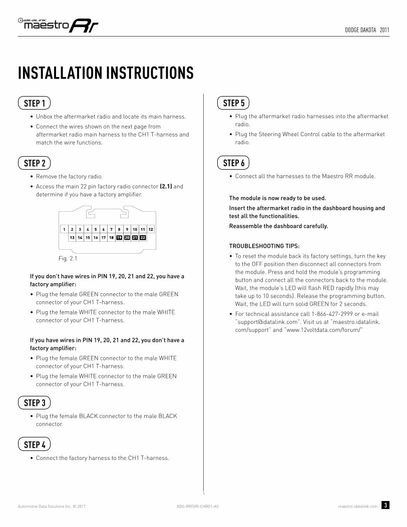
INSTALLATION INSTRUCTIONS STEP 1
• Unbox the aftermarket radio and locate its main harness.
• Connect the wires shown on the next page from aftermarket radio main harness to the CH1 T-harness and match the wire functions.
STEP 2
• Remove the factory radio.
• Access the main 22 pin factory radio connector (2.1) and determine if you have a factory amplifi er.
If you don’t have wires in PIN 19, 20, 21 and 22, you have a factory amplifi er:
• Plug the female GREEN connector to the male GREEN connector of your CH1 T-harness.
• Plug the female WHITE connector to the male WHITE connector of your CH1 T-harness.
If you have wires in PIN 19, 20, 21 and 22, you don’t have a factory amplifi er:
• Plug the female GREEN connector to the male WHITE connector of your CH1 T-harness.
• Plug the female WHITE connector to the male GREEN connector of your CH1 T-harness.
STEP 3• Plug the female RED connector to the male BLACK
connector.
STEP 4• Connect the factory harness to the CH1 T-harness.
STEP 5• Plug the aftermarket radio harnesses into the aftermarket
radio.
• Plug the Steering Wheel Control cable to the aftermarket radio.
STEP 6• Connect all the harnesses to the Maestro RR module.
The module is now ready to be used.
Insert the aftermarket radio in the dashboard housing and test all the functionalities.
Reassemble the dashboard carefully.
TROUBLESHOOTING TIPS:
• To reset the module back its factory settings, turn the key to the OFF position then disconnect all connectors from the module. Press and hold the module’s programming button and connect all the connectors back to the module. Wait, the module’s LED will fl ash RED rapidly (this may take up to 10 seconds). Release the programming button. Wait, the LED will turn solid GREEN for 2 seconds.
• For technical assistance call 1-866-427-2999 or e-mail “[email protected]”. Visit us at “maestro.idatalink.com/support” and “www.12voltdata.com/forum/”
87651 109
19181716
432
151413 21
11 12
2220
Fig. 2.1
2

ADS-RR(SR)-CHR01-AS maestro.idatalink.com
dodge dakota 2008-2010
Automotive Data Solutions Inc. © 2017 4
C
A FG
C
A
G
F
2
E
E
BROWN - MUTE (-)
WIRING DIAGRAMSTEP 1
STEP 2
STEP 3
STEP 4
STEP 5
STEP 6
MAESTRO RR MODULE
WHITE - LF SPEAKER (+)WHITE/BLACK - LF SPEAKER (-)GRAY - RF SPEAKER (+)GRAY/BLACK - RF SPEAKER (-)GREEN - LR SPEAKER (+)GREEN/BLACK - LR SPEAKER (-)
PURPLE/BLACK - RR SPEAKER (-)
YELLOW - 12V (+)
BLACK - GROUNDRED - ACCESSORY (+)
GREEN WHITE
WHITE GREEN
CONNECTIONS WITHOUT AMP
CONNECTIONS WITH AMP
ORANGE - ILLUMINATION (+)PURPLE/WHITE - REVERSE LIGHT (+)LTGREEN - E-BRAKE (-)
BLUE/WHITE - AMP. TURN ON (+)
MAINHARNESS
PURPLE - RR SPEAKER (+)
CONNECT TOAFTERMARKET RADIO
CH1 T-HARNESS
FACTORY RADIOHARNESS
RED/BROWN (NC)YELLOW/BROWN (NC)
WIRES FROMVEHICLE
PINK - VEHICLE SPEED (CONNECT IF THERE IS A MATCH)
GREEN GREEN
WHITEWHITE
BLACKRED
BLACK (NC)
STEERING WHEELCONTROL CABLE

OPTIONAL ACCESSORIESADS-HRN(AV)-CHR01
PROGRAMMED FIRMWAREADS-RR(SR)-CHR01-AS
PRODUCTS REQUIREDiDatalink Maestro RR Radio Replacement InterfaceiDatalink Maestro CH1 Installation Harness
INSTALL GUIDEDODGE DAkOTA
2011retains steering wheel controls and more!
NOTICE: Automotive Data Solutions Inc. (ADS) recommends having this installation performed by a certified technician. Logos and trademarks used here in are the properties of their respective owners.

ADS-RR(SR)-CHR01-AS maestro.idatalink.com
dodge dakota 2011
Automotive Data Solutions Inc. © 2017 2
WELCOME
NEED hELP?
Congratulations on the purchase of your iDatalink Maestro RR Radio replacement solution. You are now a few simple steps away from enjoying your new car radio with enhanced features. Before starting your installation, please ensure that your iDatalink Maestro module is programmed with the correct fi rmware for your vehicle as per the Getting Started section, and that you carefully review the Installation Diagram and Vehicle Wire Reference Chart.
Please note that Maestro RR will only retain functionalities that were originally available in the vehicle.
1 866 427-2999
maestro.idatalink.com/supportwww.12voltdata.com/forum
DURING INSTALLATION
Installation Instructions 3
Wiring Diagram 4
ADS-RR(SR)-CHR01-AS maestro.idatalink.com
dodge dakota 2011
Automotive Data Solutions Inc. © 2017 3
INSTALLATION INSTRUCTIONS STEP 1
• Unbox the aftermarket radio and locate its main harness.
• Connect the wires shown on the next page from aftermarket radio main harness to the CH1 T-harness and match the wire functions.
STEP 2
• Remove the factory radio.
• Access the main 22 pin factory radio connector (2.1) and determine if you have a factory amplifi er.
If you don’t have wires in PIN 19, 20, 21 and 22, you have a factory amplifi er:
• Plug the female GREEN connector to the male GREEN connector of your CH1 T-harness.
• Plug the female WHITE connector to the male WHITE connector of your CH1 T-harness.
If you have wires in PIN 19, 20, 21 and 22, you don’t have a factory amplifi er:
• Plug the female GREEN connector to the male WHITE connector of your CH1 T-harness.
• Plug the female WHITE connector to the male GREEN connector of your CH1 T-harness.
STEP 3• Plug the female BLACK connector to the male BLACK
connector.
STEP 4• Connect the factory harness to the CH1 T-harness.
STEP 5• Plug the aftermarket radio harnesses into the aftermarket
radio.
• Plug the Steering Wheel Control cable to the aftermarket radio.
STEP 6• Connect all the harnesses to the Maestro RR module.
The module is now ready to be used.
Insert the aftermarket radio in the dashboard housing and test all the functionalities.
Reassemble the dashboard carefully.
TROUBLESHOOTING TIPS:
• To reset the module back its factory settings, turn the key to the OFF position then disconnect all connectors from the module. Press and hold the module’s programming button and connect all the connectors back to the module. Wait, the module’s LED will fl ash RED rapidly (this may take up to 10 seconds). Release the programming button. Wait, the LED will turn solid GREEN for 2 seconds.
• For technical assistance call 1-866-427-2999 or e-mail “[email protected]”. Visit us at “maestro.idatalink.com/support” and “www.12voltdata.com/forum/”
87651 109
19181716
432
151413 21
11 12
2220
Fig. 2.1
1
ADS-RR(SR)-CHR01-AS maestro.idatalink.com
dodge dakota 2011
Automotive Data Solutions Inc. © 2017 4
C
A FG
C
A
G
F
1
E
E
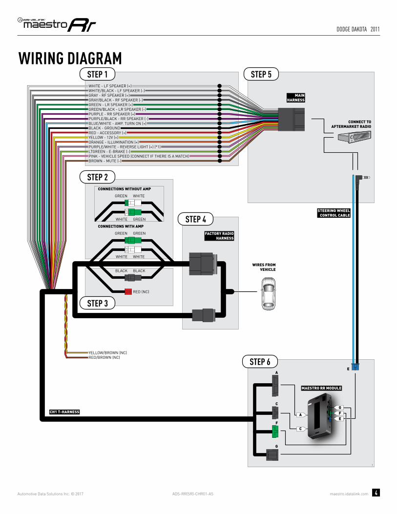
WIRING DIAGRAMSTEP 1
STEP 2
STEP 3
STEP 4
STEP 5
STEP 6
MAESTRO RR MODULE
WHITE - LF SPEAKER (+)WHITE/BLACK - LF SPEAKER (-)GRAY - RF SPEAKER (+)GRAY/BLACK - RF SPEAKER (-)GREEN - LR SPEAKER (+)GREEN/BLACK - LR SPEAKER (-)
PURPLE/BLACK - RR SPEAKER (-)
YELLOW - 12V (+)
BLACK - GROUNDRED - ACCESSORY (+)
GREEN WHITE
WHITE GREEN
CONNECTIONS WITHOUT AMP
CONNECTIONS WITH AMP
ORANGE - ILLUMINATION (+)PURPLE/WHITE - REVERSE LIGHT (+) (*1)LTGREEN - E-BRAKE (-)
BLUE/WHITE - AMP. TURN ON (+)
MAINHARNESS
PURPLE - RR SPEAKER (+)
CONNECT TOAFTERMARKET RADIO
CH1 T-HARNESS
FACTORY RADIOHARNESS
RED/BROWN (NC)YELLOW/BROWN (NC)
WIRES FROMVEHICLE
PINK - VEHICLE SPEED (CONNECT IF THERE IS A MATCH)
GREEN GREEN
WHITEWHITE
BLACKBLACK
STEERING WHEELCONTROL CABLE
RED (NC)
BROWN - MUTE (-)

OPTIONAL ACCESSORIESADS-HRN(AV)-CHR01
PROGRAMMED FIRMWAREADS-RR(SR)-CHR01-AS
PRODUCTS REQUIREDiDatalink Maestro RR Radio Replacement InterfaceiDatalink Maestro CH1 Installation Harness
INSTALL GUIDEDODGE DURANGO
2008-2009retains steering wheel controls and more!
NOTICE: Automotive Data Solutions Inc. (ADS) recommends having this installation performed by a certified technician. Logos and trademarks used here in are the properties of their respective owners.
ADS-RR(SR)-CHR01-AS maestro.idatalink.com
dodge durango 2008-2009
Automotive Data Solutions Inc. © 2017 2
WELCOME
NEED hELP?
Congratulations on the purchase of your iDatalink Maestro RR Radio replacement solution. You are now a few simple steps away from enjoying your new car radio with enhanced features. Before starting your installation, please ensure that your iDatalink Maestro module is programmed with the correct fi rmware for your vehicle as per the Getting Started section, and that you carefully review the Installation Diagram and Vehicle Wire Reference Chart.
Please note that Maestro RR will only retain functionalities that were originally available in the vehicle.
1 866 427-2999
maestro.idatalink.com/supportwww.12voltdata.com/forum
DURING INSTALLATION
Installation Instructions 3
Wiring Diagram 4
ADS-RR(SR)-CHR01-AS maestro.idatalink.com
dodge durango 2008-2009
Automotive Data Solutions Inc. © 2017 3
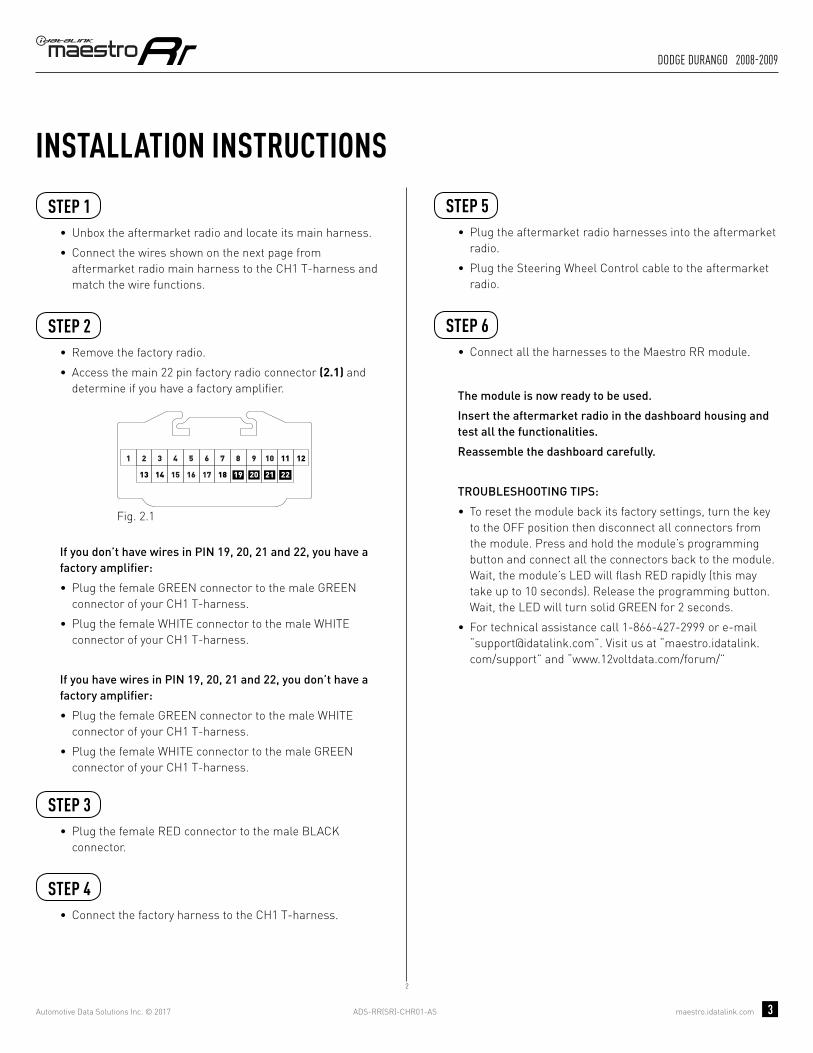
INSTALLATION INSTRUCTIONS STEP 1
• Unbox the aftermarket radio and locate its main harness.
• Connect the wires shown on the next page from aftermarket radio main harness to the CH1 T-harness and match the wire functions.
STEP 2
• Remove the factory radio.
• Access the main 22 pin factory radio connector (2.1) and determine if you have a factory amplifi er.
If you don’t have wires in PIN 19, 20, 21 and 22, you have a factory amplifi er:
• Plug the female GREEN connector to the male GREEN connector of your CH1 T-harness.
• Plug the female WHITE connector to the male WHITE connector of your CH1 T-harness.
If you have wires in PIN 19, 20, 21 and 22, you don’t have a factory amplifi er:
• Plug the female GREEN connector to the male WHITE connector of your CH1 T-harness.
• Plug the female WHITE connector to the male GREEN connector of your CH1 T-harness.
STEP 3• Plug the female RED connector to the male BLACK
connector.
STEP 4• Connect the factory harness to the CH1 T-harness.
STEP 5• Plug the aftermarket radio harnesses into the aftermarket
radio.
• Plug the Steering Wheel Control cable to the aftermarket radio.
STEP 6• Connect all the harnesses to the Maestro RR module.
The module is now ready to be used.
Insert the aftermarket radio in the dashboard housing and test all the functionalities.
Reassemble the dashboard carefully.
TROUBLESHOOTING TIPS:
• To reset the module back its factory settings, turn the key to the OFF position then disconnect all connectors from the module. Press and hold the module’s programming button and connect all the connectors back to the module. Wait, the module’s LED will fl ash RED rapidly (this may take up to 10 seconds). Release the programming button. Wait, the LED will turn solid GREEN for 2 seconds.
• For technical assistance call 1-866-427-2999 or e-mail “[email protected]”. Visit us at “maestro.idatalink.com/support” and “www.12voltdata.com/forum/”
87651 109
19181716
432
151413 21
11 12
2220
Fig. 2.1
2
ADS-RR(SR)-CHR01-AS maestro.idatalink.com
dodge durango 2008-2009
Automotive Data Solutions Inc. © 2017 4
C
A FG
C
A
G
F
2
E
E
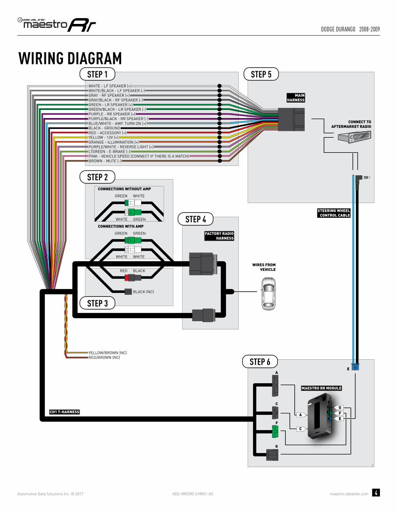
BROWN - MUTE (-)
WIRING DIAGRAMSTEP 1
STEP 2
STEP 3
STEP 4
STEP 5
STEP 6
MAESTRO RR MODULE
WHITE - LF SPEAKER (+)WHITE/BLACK - LF SPEAKER (-)GRAY - RF SPEAKER (+)GRAY/BLACK - RF SPEAKER (-)GREEN - LR SPEAKER (+)GREEN/BLACK - LR SPEAKER (-)
PURPLE/BLACK - RR SPEAKER (-)
YELLOW - 12V (+)
BLACK - GROUNDRED - ACCESSORY (+)
GREEN WHITE
WHITE GREEN
CONNECTIONS WITHOUT AMP
CONNECTIONS WITH AMP
ORANGE - ILLUMINATION (+)PURPLE/WHITE - REVERSE LIGHT (+)LTGREEN - E-BRAKE (-)
BLUE/WHITE - AMP. TURN ON (+)
MAINHARNESS
PURPLE - RR SPEAKER (+)
CONNECT TOAFTERMARKET RADIO
CH1 T-HARNESS
FACTORY RADIOHARNESS
RED/BROWN (NC)YELLOW/BROWN (NC)
WIRES FROMVEHICLE
PINK - VEHICLE SPEED (CONNECT IF THERE IS A MATCH)
GREEN GREEN
WHITEWHITE
BLACKRED
BLACK (NC)
STEERING WHEELCONTROL CABLE

OPTIONAL ACCESSORIESADS-HRN(AV)-CHR01
PROGRAMMED FIRMWAREADS-RR(SR)-CHR01-AS
PRODUCTS REQUIREDiDatalink Maestro RR Radio Replacement InterfaceiDatalink Maestro CH1 Installation Harness
INSTALL GUIDEDODGE DURANGO
2011-2013retains steering wheel controls and more!
NOTICE: Automotive Data Solutions Inc. (ADS) recommends having this installation performed by a certified technician. Logos and trademarks used here in are the properties of their respective owners.

ADS-RR(SR)-CHR01-AS maestro.idatalink.com
dodge durango 2011-2013
Automotive Data Solutions Inc. © 2017 2
WELCOME
NEED hELP?
Congratulations on the purchase of your iDatalink Maestro RR Radio replacement solution. You are now a few simple steps away from enjoying your new car radio with enhanced features. Before starting your installation, please ensure that your iDatalink Maestro module is programmed with the correct fi rmware for your vehicle as per the Getting Started section, and that you carefully review the Installation Diagram and Vehicle Wire Reference Chart.
Please note that Maestro RR will only retain functionalities that were originally available in the vehicle.
1 866 427-2999
maestro.idatalink.com/supportwww.12voltdata.com/forum
DURING INSTALLATION
Installation Instructions 3
Wiring Diagram 4

ADS-RR(SR)-CHR01-AS maestro.idatalink.com
dodge durango 2011-2013
Automotive Data Solutions Inc. © 2017 3
INSTALLATION INSTRUCTIONS STEP 1
• Unbox the aftermarket radio and locate its main harness.
• Connect the wires shown on the next page from aftermarket radio main harness to the CH1 T-harness and match the wire functions.
STEP 2
• Remove the factory radio.
• Access the main 22 pin factory radio connector (2.1) and determine if you have a factory amplifi er.
If you don’t have wires in PIN 19, 20, 21 and 22, you have a factory amplifi er:
• Plug the female GREEN connector to the male GREEN connector of your CH1 T-harness.
• Plug the female WHITE connector to the male WHITE connector of your CH1 T-harness.
If you have wires in PIN 19, 20, 21 and 22, you don’t have a factory amplifi er:
• Plug the female GREEN connector to the male WHITE connector of your CH1 T-harness.
• Plug the female WHITE connector to the male GREEN connector of your CH1 T-harness.
STEP 3• Plug the female BLACK connector to the male BLACK
connector.
STEP 4• Connect the factory harness to the CH1 T-harness.
STEP 5• Plug the aftermarket radio harnesses into the aftermarket
radio.
• Plug the Steering Wheel Control cable to the aftermarket radio.
STEP 6• Connect all the harnesses to the Maestro RR module.
The module is now ready to be used.
Insert the aftermarket radio in the dashboard housing and test all the functionalities.
Reassemble the dashboard carefully.
TROUBLESHOOTING TIPS:
• To reset the module back its factory settings, turn the key to the OFF position then disconnect all connectors from the module. Press and hold the module’s programming button and connect all the connectors back to the module. Wait, the module’s LED will fl ash RED rapidly (this may take up to 10 seconds). Release the programming button. Wait, the LED will turn solid GREEN for 2 seconds.
• For technical assistance call 1-866-427-2999 or e-mail “[email protected]”. Visit us at “maestro.idatalink.com/support” and “www.12voltdata.com/forum/”
87651 109
19181716
432
151413 21
11 12
2220
Fig. 2.1
1

ADS-RR(SR)-CHR01-AS maestro.idatalink.com
dodge durango 2011-2013
Automotive Data Solutions Inc. © 2017 4
C
A FG
C
A
G
F
1
E
E
WIRING DIAGRAMSTEP 1
STEP 2
STEP 3
STEP 4
STEP 5
STEP 6
MAESTRO RR MODULE
WHITE - LF SPEAKER (+)WHITE/BLACK - LF SPEAKER (-)GRAY - RF SPEAKER (+)GRAY/BLACK - RF SPEAKER (-)GREEN - LR SPEAKER (+)GREEN/BLACK - LR SPEAKER (-)
PURPLE/BLACK - RR SPEAKER (-)
YELLOW - 12V (+)
BLACK - GROUNDRED - ACCESSORY (+)
GREEN WHITE
WHITE GREEN
CONNECTIONS WITHOUT AMP
CONNECTIONS WITH AMP
ORANGE - ILLUMINATION (+)PURPLE/WHITE - REVERSE LIGHT (+) (*1)LTGREEN - E-BRAKE (-)
BLUE/WHITE - AMP. TURN ON (+)
MAINHARNESS
PURPLE - RR SPEAKER (+)
CONNECT TOAFTERMARKET RADIO
CH1 T-HARNESS
FACTORY RADIOHARNESS
RED/BROWN (NC)YELLOW/BROWN (NC)
WIRES FROMVEHICLE
PINK - VEHICLE SPEED (CONNECT IF THERE IS A MATCH)
GREEN GREEN
WHITEWHITE
BLACKBLACK
STEERING WHEELCONTROL CABLE
RED (NC)
BROWN - MUTE (-)

OPTIONAL ACCESSORIESADS-HRN(AV)-CHR01
PROGRAMMED FIRMWAREADS-RR(SR)-CHR01-AS
PRODUCTS REQUIREDiDatalink Maestro RR Radio Replacement InterfaceiDatalink Maestro CH1 Installation Harness
INSTALL GUIDEDODGE GRAND CARAvAN
2008-2011retains steering wheel controls and more!
NOTICE: Automotive Data Solutions Inc. (ADS) recommends having this installation performed by a certified technician. Logos and trademarks used here in are the properties of their respective owners.
ADS-RR(SR)-CHR01-AS maestro.idatalink.com
dodge grand caravan 2008-2011
Automotive Data Solutions Inc. © 2017 2
WELCOME
NEED hELP?
Congratulations on the purchase of your iDatalink Maestro RR Radio replacement solution. You are now a few simple steps away from enjoying your new car radio with enhanced features. Before starting your installation, please ensure that your iDatalink Maestro module is programmed with the correct fi rmware for your vehicle as per the Getting Started section, and that you carefully review the Installation Diagram and Vehicle Wire Reference Chart.
Please note that Maestro RR will only retain functionalities that were originally available in the vehicle.
1 866 427-2999
maestro.idatalink.com/supportwww.12voltdata.com/forum
DURING INSTALLATION
Installation Instructions 3
Wiring Diagram 4

ADS-RR(SR)-CHR01-AS maestro.idatalink.com
dodge grand caravan 2008-2011
Automotive Data Solutions Inc. © 2017 3
INSTALLATION INSTRUCTIONS STEP 1
• Unbox the aftermarket radio and locate its main harness.
• Connect the wires shown on the next page from aftermarket radio main harness to the CH1 T-harness and match the wire functions.
STEP 2
• Remove the factory radio.
• Access the main 22 pin factory radio connector (2.1) and determine if you have a factory amplifi er.
If you don’t have wires in PIN 19, 20, 21 and 22, you have a factory amplifi er:
• Plug the female GREEN connector to the male GREEN connector of your CH1 T-harness.
• Plug the female WHITE connector to the male WHITE connector of your CH1 T-harness.
If you have wires in PIN 19, 20, 21 and 22, you don’t have a factory amplifi er:
• Plug the female GREEN connector to the male WHITE connector of your CH1 T-harness.
• Plug the female WHITE connector to the male GREEN connector of your CH1 T-harness.
STEP 3• Plug the female BLACK connector to the male BLACK
connector.
STEP 4• Connect the factory harness to the CH1 T-harness.
STEP 5• Plug the aftermarket radio harnesses into the aftermarket
radio.
• Plug the Steering Wheel Control cable to the aftermarket radio.
STEP 6• Connect all the harnesses to the Maestro RR module.
The module is now ready to be used.
Insert the aftermarket radio in the dashboard housing and test all the functionalities.
Reassemble the dashboard carefully.
TROUBLESHOOTING TIPS:
• To reset the module back its factory settings, turn the key to the OFF position then disconnect all connectors from the module. Press and hold the module’s programming button and connect all the connectors back to the module. Wait, the module’s LED will fl ash RED rapidly (this may take up to 10 seconds). Release the programming button. Wait, the LED will turn solid GREEN for 2 seconds.
• For technical assistance call 1-866-427-2999 or e-mail “[email protected]”. Visit us at “maestro.idatalink.com/support” and “www.12voltdata.com/forum/”
87651 109
19181716
432
151413 21
11 12
2220
Fig. 2.1
1

ADS-RR(SR)-CHR01-AS maestro.idatalink.com
dodge grand caravan 2008-2011
Automotive Data Solutions Inc. © 2017 4
C
A FG
C
A
G
F
1
E
E
WIRING DIAGRAMSTEP 1
STEP 2
STEP 3
STEP 4
STEP 5
STEP 6
MAESTRO RR MODULE
WHITE - LF SPEAKER (+)WHITE/BLACK - LF SPEAKER (-)GRAY - RF SPEAKER (+)GRAY/BLACK - RF SPEAKER (-)GREEN - LR SPEAKER (+)GREEN/BLACK - LR SPEAKER (-)
PURPLE/BLACK - RR SPEAKER (-)
YELLOW - 12V (+)
BLACK - GROUNDRED - ACCESSORY (+)
GREEN WHITE
WHITE GREEN
CONNECTIONS WITHOUT AMP
CONNECTIONS WITH AMP
ORANGE - ILLUMINATION (+)PURPLE/WHITE - REVERSE LIGHT (+) (*1)LTGREEN - E-BRAKE (-)
BLUE/WHITE - AMP. TURN ON (+)
MAINHARNESS
PURPLE - RR SPEAKER (+)
CONNECT TOAFTERMARKET RADIO
CH1 T-HARNESS
FACTORY RADIOHARNESS
RED/BROWN (NC)YELLOW/BROWN (NC)
WIRES FROMVEHICLE
PINK - VEHICLE SPEED (CONNECT IF THERE IS A MATCH)
GREEN GREEN
WHITEWHITE
BLACKBLACK
STEERING WHEELCONTROL CABLE
RED (NC)
BROWN - MUTE (-)

OPTIONAL ACCESSORIESADS-HRN(AV)-CHR01
PROGRAMMED FIRMWAREADS-RR(SR)-CHR01-AS
PRODUCTS REQUIREDiDatalink Maestro RR Radio Replacement InterfaceiDatalink Maestro CH1 Installation Harness
INSTALL GUIDEDODGE GRAND CARAvAN
2012-2017retains steering wheel controls and more!
NOTICE: Automotive Data Solutions Inc. (ADS) recommends having this installation performed by a certified technician. Logos and trademarks used here in are the properties of their respective owners.

ADS-RR(SR)-CHR01-AS maestro.idatalink.com
dodge grand caravan 2012-2017
Automotive Data Solutions Inc. © 2017 2
WELCOME
NEED hELP?
Congratulations on the purchase of your iDatalink Maestro RR Radio replacement solution. You are now a few simple steps away from enjoying your new car radio with enhanced features. Before starting your installation, please ensure that your iDatalink Maestro module is programmed with the correct fi rmware for your vehicle as per the Getting Started section, and that you carefully review the Installation Diagram and Vehicle Wire Reference Chart.
Please note that Maestro RR will only retain functionalities that were originally available in the vehicle.
1 866 427-2999
maestro.idatalink.com/supportwww.12voltdata.com/forum
DURING INSTALLATION
Installation Instructions 3
Wiring Diagram 4

ADS-RR(SR)-CHR01-AS maestro.idatalink.com
dodge grand caravan 2012-2017
Automotive Data Solutions Inc. © 2017 3
INSTALLATION INSTRUCTIONS STEP 1
• Unbox the aftermarket radio and locate its main harness.
• Connect the wires shown on the next page from aftermarket radio main harness to the CH1 T-harness and match the wire functions.
STEP 2
• Remove the factory radio.
• Access the main 22 pin factory radio connector (2.1) and determine if you have a factory amplifi er.
If you don’t have wires in PIN 19, 20, 21 and 22, you have a factory amplifi er:
• Plug the female GREEN connector to the male GREEN connector of your CH1 T-harness.
• Plug the female WHITE connector to the male WHITE connector of your CH1 T-harness.
If you have wires in PIN 19, 20, 21 and 22, you don’t have a factory amplifi er:
• Plug the female GREEN connector to the male WHITE connector of your CH1 T-harness.
• Plug the female WHITE connector to the male GREEN connector of your CH1 T-harness.
STEP 3• Plug the female BLACK connector to the male BLACK
connector.
STEP 4• Connect the factory harness to the CH1 T-harness.
STEP 5• Plug the aftermarket radio harnesses into the aftermarket
radio.
• Plug the Steering Wheel Control cable to the aftermarket radio.
STEP 6• Connect all the harnesses to the Maestro RR module.
The module is now ready to be used.
Insert the aftermarket radio in the dashboard housing and test all the functionalities.
Reassemble the dashboard carefully.
TROUBLESHOOTING TIPS:
• To reset the module back its factory settings, turn the key to the OFF position then disconnect all connectors from the module. Press and hold the module’s programming button and connect all the connectors back to the module. Wait, the module’s LED will fl ash RED rapidly (this may take up to 10 seconds). Release the programming button. Wait, the LED will turn solid GREEN for 2 seconds.
• For technical assistance call 1-866-427-2999 or e-mail “[email protected]”. Visit us at “maestro.idatalink.com/support” and “www.12voltdata.com/forum/”
87651 109
19181716
432
151413 21
11 12
2220
Fig. 2.1
1

ADS-RR(SR)-CHR01-AS maestro.idatalink.com
dodge grand caravan 2012-2017
Automotive Data Solutions Inc. © 2017 4
C
A FG
C
A
G
F
1
E
E
WIRING DIAGRAMSTEP 1
STEP 2
STEP 3
STEP 4
STEP 5
STEP 6
MAESTRO RR MODULE
WHITE - LF SPEAKER (+)WHITE/BLACK - LF SPEAKER (-)GRAY - RF SPEAKER (+)GRAY/BLACK - RF SPEAKER (-)GREEN - LR SPEAKER (+)GREEN/BLACK - LR SPEAKER (-)
PURPLE/BLACK - RR SPEAKER (-)
YELLOW - 12V (+)
BLACK - GROUNDRED - ACCESSORY (+)
GREEN WHITE
WHITE GREEN
CONNECTIONS WITHOUT AMP
CONNECTIONS WITH AMP
ORANGE - ILLUMINATION (+)PURPLE/WHITE - REVERSE LIGHT (+) (*1)LTGREEN - E-BRAKE (-)
BLUE/WHITE - AMP. TURN ON (+)
MAINHARNESS
PURPLE - RR SPEAKER (+)
CONNECT TOAFTERMARKET RADIO
CH1 T-HARNESS
FACTORY RADIOHARNESS
RED/BROWN (NC)YELLOW/BROWN (NC)
WIRES FROMVEHICLE
PINK - VEHICLE SPEED (CONNECT IF THERE IS A MATCH)
GREEN GREEN
WHITEWHITE
BLACKBLACK
STEERING WHEELCONTROL CABLE
RED (NC)
BROWN - MUTE (-)

OPTIONAL ACCESSORIESADS-HRN(AV)-CHR01
PROGRAMMED FIRMWAREADS-RR(SR)-CHR01-AS
PRODUCTS REQUIREDiDatalink Maestro RR Radio Replacement InterfaceiDatalink Maestro CH1 Installation Harness
INSTALL GUIDEDODGE JOURNEy
2009-2010retains steering wheel controls and more!
NOTICE: Automotive Data Solutions Inc. (ADS) recommends having this installation performed by a certified technician. Logos and trademarks used here in are the properties of their respective owners.

ADS-RR(SR)-CHR01-AS maestro.idatalink.com
dodge Journey 2009-2010
Automotive Data Solutions Inc. © 2017 2
WELCOME
NEED hELP?
Congratulations on the purchase of your iDatalink Maestro RR Radio replacement solution. You are now a few simple steps away from enjoying your new car radio with enhanced features. Before starting your installation, please ensure that your iDatalink Maestro module is programmed with the correct fi rmware for your vehicle as per the Getting Started section, and that you carefully review the Installation Diagram and Vehicle Wire Reference Chart.
Please note that Maestro RR will only retain functionalities that were originally available in the vehicle.
1 866 427-2999
maestro.idatalink.com/supportwww.12voltdata.com/forum
DURING INSTALLATION
Installation Instructions 3
Wiring Diagram 4

ADS-RR(SR)-CHR01-AS maestro.idatalink.com
dodge Journey 2009-2010
Automotive Data Solutions Inc. © 2017 3
INSTALLATION INSTRUCTIONS STEP 1
• Unbox the aftermarket radio and locate its main harness.
• Connect the wires shown on the next page from aftermarket radio main harness to the CH1 T-harness and match the wire functions.
STEP 2
• Remove the factory radio.
• Access the main 22 pin factory radio connector (2.1) and determine if you have a factory amplifi er.
If you don’t have wires in PIN 19, 20, 21 and 22, you have a factory amplifi er:
• Plug the female GREEN connector to the male GREEN connector of your CH1 T-harness.
• Plug the female WHITE connector to the male WHITE connector of your CH1 T-harness.
If you have wires in PIN 19, 20, 21 and 22, you don’t have a factory amplifi er:
• Plug the female GREEN connector to the male WHITE connector of your CH1 T-harness.
• Plug the female WHITE connector to the male GREEN connector of your CH1 T-harness.
STEP 3• Plug the female BLACK connector to the male BLACK
connector.
STEP 4• Connect the factory harness to the CH1 T-harness.
STEP 5• Plug the aftermarket radio harnesses into the aftermarket
radio.
• Plug the Steering Wheel Control cable to the aftermarket radio.
STEP 6• Connect all the harnesses to the Maestro RR module.
The module is now ready to be used.
Insert the aftermarket radio in the dashboard housing and test all the functionalities.
Reassemble the dashboard carefully.
TROUBLESHOOTING TIPS:
• To reset the module back its factory settings, turn the key to the OFF position then disconnect all connectors from the module. Press and hold the module’s programming button and connect all the connectors back to the module. Wait, the module’s LED will fl ash RED rapidly (this may take up to 10 seconds). Release the programming button. Wait, the LED will turn solid GREEN for 2 seconds.
• For technical assistance call 1-866-427-2999 or e-mail “[email protected]”. Visit us at “maestro.idatalink.com/support” and “www.12voltdata.com/forum/”
87651 109
19181716
432
151413 21
11 12
2220
Fig. 2.1
1

ADS-RR(SR)-CHR01-AS maestro.idatalink.com
dodge Journey 2009-2010
Automotive Data Solutions Inc. © 2017 4
C
A FG
C
A
G
F
1
E
E
WIRING DIAGRAMSTEP 1
STEP 2
STEP 3
STEP 4
STEP 5
STEP 6
MAESTRO RR MODULE
WHITE - LF SPEAKER (+)WHITE/BLACK - LF SPEAKER (-)GRAY - RF SPEAKER (+)GRAY/BLACK - RF SPEAKER (-)GREEN - LR SPEAKER (+)GREEN/BLACK - LR SPEAKER (-)
PURPLE/BLACK - RR SPEAKER (-)
YELLOW - 12V (+)
BLACK - GROUNDRED - ACCESSORY (+)
GREEN WHITE
WHITE GREEN
CONNECTIONS WITHOUT AMP
CONNECTIONS WITH AMP
ORANGE - ILLUMINATION (+)PURPLE/WHITE - REVERSE LIGHT (+) (*1)LTGREEN - E-BRAKE (-)
BLUE/WHITE - AMP. TURN ON (+)
MAINHARNESS
PURPLE - RR SPEAKER (+)
CONNECT TOAFTERMARKET RADIO
CH1 T-HARNESS
FACTORY RADIOHARNESS
RED/BROWN (NC)YELLOW/BROWN (NC)
WIRES FROMVEHICLE
PINK - VEHICLE SPEED (CONNECT IF THERE IS A MATCH)
GREEN GREEN
WHITEWHITE
BLACKBLACK
STEERING WHEELCONTROL CABLE
RED (NC)
BROWN - MUTE (-)

OPTIONAL ACCESSORIESADS-HRN(AV)-CHR01
PROGRAMMED FIRMWAREADS-RR(SR)-CHR01-AS
PRODUCTS REQUIREDiDatalink Maestro RR Radio Replacement InterfaceiDatalink Maestro CH1 Installation Harness
INSTALL GUIDEDODGE NITRO
2007-2011retains steering wheel controls and more!
NOTICE: Automotive Data Solutions Inc. (ADS) recommends having this installation performed by a certified technician. Logos and trademarks used here in are the properties of their respective owners.

ADS-RR(SR)-CHR01-AS maestro.idatalink.com
dodge nitro 2007-2011
Automotive Data Solutions Inc. © 2017 2
WELCOME
NEED hELP?
Congratulations on the purchase of your iDatalink Maestro RR Radio replacement solution. You are now a few simple steps away from enjoying your new car radio with enhanced features. Before starting your installation, please ensure that your iDatalink Maestro module is programmed with the correct fi rmware for your vehicle as per the Getting Started section, and that you carefully review the Installation Diagram and Vehicle Wire Reference Chart.
Please note that Maestro RR will only retain functionalities that were originally available in the vehicle.
1 866 427-2999
maestro.idatalink.com/supportwww.12voltdata.com/forum
DURING INSTALLATION
Installation Instructions 3
Wiring Diagram 4

ADS-RR(SR)-CHR01-AS maestro.idatalink.com
dodge nitro 2007-2011
Automotive Data Solutions Inc. © 2017 3
INSTALLATION INSTRUCTIONS STEP 1
• Unbox the aftermarket radio and locate its main harness.
• Connect the wires shown on the next page from aftermarket radio main harness to the CH1 T-harness and match the wire functions.
STEP 2
• Remove the factory radio.
• Access the main 22 pin factory radio connector (2.1) and determine if you have a factory amplifi er.
If you don’t have wires in PIN 19, 20, 21 and 22, you have a factory amplifi er:
• Plug the female GREEN connector to the male GREEN connector of your CH1 T-harness.
• Plug the female WHITE connector to the male WHITE connector of your CH1 T-harness.
If you have wires in PIN 19, 20, 21 and 22, you don’t have a factory amplifi er:
• Plug the female GREEN connector to the male WHITE connector of your CH1 T-harness.
• Plug the female WHITE connector to the male GREEN connector of your CH1 T-harness.
STEP 3• Plug the female BLACK connector to the male BLACK
connector.
STEP 4• Connect the factory harness to the CH1 T-harness.
STEP 5• Plug the aftermarket radio harnesses into the aftermarket
radio.
• Plug the Steering Wheel Control cable to the aftermarket radio.
STEP 6• Connect all the harnesses to the Maestro RR module.
The module is now ready to be used.
Insert the aftermarket radio in the dashboard housing and test all the functionalities.
Reassemble the dashboard carefully.
TROUBLESHOOTING TIPS:
• To reset the module back its factory settings, turn the key to the OFF position then disconnect all connectors from the module. Press and hold the module’s programming button and connect all the connectors back to the module. Wait, the module’s LED will fl ash RED rapidly (this may take up to 10 seconds). Release the programming button. Wait, the LED will turn solid GREEN for 2 seconds.
• For technical assistance call 1-866-427-2999 or e-mail “[email protected]”. Visit us at “maestro.idatalink.com/support” and “www.12voltdata.com/forum/”
87651 109
19181716
432
151413 21
11 12
2220
Fig. 2.1
1

ADS-RR(SR)-CHR01-AS maestro.idatalink.com
dodge nitro 2007-2011
Automotive Data Solutions Inc. © 2017 4
C
A FG
C
A
G
F
1
E
E
WIRING DIAGRAMSTEP 1
STEP 2
STEP 3
STEP 4
STEP 5
STEP 6
MAESTRO RR MODULE
WHITE - LF SPEAKER (+)WHITE/BLACK - LF SPEAKER (-)GRAY - RF SPEAKER (+)GRAY/BLACK - RF SPEAKER (-)GREEN - LR SPEAKER (+)GREEN/BLACK - LR SPEAKER (-)
PURPLE/BLACK - RR SPEAKER (-)
YELLOW - 12V (+)
BLACK - GROUNDRED - ACCESSORY (+)
GREEN WHITE
WHITE GREEN
CONNECTIONS WITHOUT AMP
CONNECTIONS WITH AMP
ORANGE - ILLUMINATION (+)PURPLE/WHITE - REVERSE LIGHT (+) (*1)LTGREEN - E-BRAKE (-)
BLUE/WHITE - AMP. TURN ON (+)
MAINHARNESS
PURPLE - RR SPEAKER (+)
CONNECT TOAFTERMARKET RADIO
CH1 T-HARNESS
FACTORY RADIOHARNESS
RED/BROWN (NC)YELLOW/BROWN (NC)
WIRES FROMVEHICLE
PINK - VEHICLE SPEED (CONNECT IF THERE IS A MATCH)
GREEN GREEN
WHITEWHITE
BLACKBLACK
STEERING WHEELCONTROL CABLE
RED (NC)
BROWN - MUTE (-)

OPTIONAL ACCESSORIESADS-HRN(AV)-CHR01
PROGRAMMED FIRMWAREADS-RR(SR)-CHR01-AS
PRODUCTS REQUIREDiDatalink Maestro RR Radio Replacement InterfaceiDatalink Maestro CH1 Installation Harness
INSTALL GUIDEJEEP COMMANDER
2008-2010retains steering wheel controls and more!
NOTICE: Automotive Data Solutions Inc. (ADS) recommends having this installation performed by a certified technician. Logos and trademarks used here in are the properties of their respective owners.

ADS-RR(SR)-CHR01-AS maestro.idatalink.com
Jeep commander 2008-2010
Automotive Data Solutions Inc. © 2017 2
WELCOME
NEED hELP?
Congratulations on the purchase of your iDatalink Maestro RR Radio replacement solution. You are now a few simple steps away from enjoying your new car radio with enhanced features. Before starting your installation, please ensure that your iDatalink Maestro module is programmed with the correct fi rmware for your vehicle as per the Getting Started section, and that you carefully review the Installation Diagram and Vehicle Wire Reference Chart.
Please note that Maestro RR will only retain functionalities that were originally available in the vehicle.
1 866 427-2999
maestro.idatalink.com/supportwww.12voltdata.com/forum
DURING INSTALLATION
Installation Instructions 3
Wiring Diagram 4

ADS-RR(SR)-CHR01-AS maestro.idatalink.com
Jeep commander 2008-2010
Automotive Data Solutions Inc. © 2017 3
INSTALLATION INSTRUCTIONS STEP 1
• Unbox the aftermarket radio and locate its main harness.
• Connect the wires shown on the next page from aftermarket radio main harness to the CH1 T-harness and match the wire functions.
STEP 2
• Remove the factory radio.
• Access the main 22 pin factory radio connector (2.1) and determine if you have a factory amplifi er.
If you don’t have wires in PIN 19, 20, 21 and 22, you have a factory amplifi er:
• Plug the female GREEN connector to the male GREEN connector of your CH1 T-harness.
• Plug the female WHITE connector to the male WHITE connector of your CH1 T-harness.
If you have wires in PIN 19, 20, 21 and 22, you don’t have a factory amplifi er:
• Plug the female GREEN connector to the male WHITE connector of your CH1 T-harness.
• Plug the female WHITE connector to the male GREEN connector of your CH1 T-harness.
STEP 3• Plug the female RED connector to the male BLACK
connector.
STEP 4• Connect the factory harness to the CH1 T-harness.
STEP 5• Plug the aftermarket radio harnesses into the aftermarket
radio.
• Plug the Steering Wheel Control cable to the aftermarket radio.
STEP 6• Connect all the harnesses to the Maestro RR module.
The module is now ready to be used.
Insert the aftermarket radio in the dashboard housing and test all the functionalities.
Reassemble the dashboard carefully.
TROUBLESHOOTING TIPS:
• To reset the module back its factory settings, turn the key to the OFF position then disconnect all connectors from the module. Press and hold the module’s programming button and connect all the connectors back to the module. Wait, the module’s LED will fl ash RED rapidly (this may take up to 10 seconds). Release the programming button. Wait, the LED will turn solid GREEN for 2 seconds.
• For technical assistance call 1-866-427-2999 or e-mail “[email protected]”. Visit us at “maestro.idatalink.com/support” and “www.12voltdata.com/forum/”
87651 109
19181716
432
151413 21
11 12
2220
Fig. 2.1
2

ADS-RR(SR)-CHR01-AS maestro.idatalink.com
Jeep commander 2008-2010
Automotive Data Solutions Inc. © 2017 4
C
A FG
C
A
G
F
2
E
E
BROWN - MUTE (-)
WIRING DIAGRAMSTEP 1
STEP 2
STEP 3
STEP 4
STEP 5
STEP 6
MAESTRO RR MODULE
WHITE - LF SPEAKER (+)WHITE/BLACK - LF SPEAKER (-)GRAY - RF SPEAKER (+)GRAY/BLACK - RF SPEAKER (-)GREEN - LR SPEAKER (+)GREEN/BLACK - LR SPEAKER (-)
PURPLE/BLACK - RR SPEAKER (-)
YELLOW - 12V (+)
BLACK - GROUNDRED - ACCESSORY (+)
GREEN WHITE
WHITE GREEN
CONNECTIONS WITHOUT AMP
CONNECTIONS WITH AMP
ORANGE - ILLUMINATION (+)PURPLE/WHITE - REVERSE LIGHT (+)LTGREEN - E-BRAKE (-)
BLUE/WHITE - AMP. TURN ON (+)
MAINHARNESS
PURPLE - RR SPEAKER (+)
CONNECT TOAFTERMARKET RADIO
CH1 T-HARNESS
FACTORY RADIOHARNESS
RED/BROWN (NC)YELLOW/BROWN (NC)
WIRES FROMVEHICLE
PINK - VEHICLE SPEED (CONNECT IF THERE IS A MATCH)
GREEN GREEN
WHITEWHITE
BLACKRED
BLACK (NC)
STEERING WHEELCONTROL CABLE

OPTIONAL ACCESSORIESADS-HRN(AV)-CHR01
PROGRAMMED FIRMWAREADS-RR(SR)-CHR01-AS
PRODUCTS REQUIREDiDatalink Maestro RR Radio Replacement InterfaceiDatalink Maestro CH1 Installation Harness
INSTALL GUIDEJEEP COMPASS
2009-2016retains steering wheel controls and more!
NOTICE: Automotive Data Solutions Inc. (ADS) recommends having this installation performed by a certified technician. Logos and trademarks used here in are the properties of their respective owners.

ADS-RR(SR)-CHR01-AS maestro.idatalink.com
Jeep compass 2009-2016
Automotive Data Solutions Inc. © 2017 2
WELCOME
NEED hELP?
Congratulations on the purchase of your iDatalink Maestro RR Radio replacement solution. You are now a few simple steps away from enjoying your new car radio with enhanced features. Before starting your installation, please ensure that your iDatalink Maestro module is programmed with the correct fi rmware for your vehicle as per the Getting Started section, and that you carefully review the Installation Diagram and Vehicle Wire Reference Chart.
Please note that Maestro RR will only retain functionalities that were originally available in the vehicle.
1 866 427-2999
maestro.idatalink.com/supportwww.12voltdata.com/forum
DURING INSTALLATION
Installation Instructions 3
Wiring Diagram 4

ADS-RR(SR)-CHR01-AS maestro.idatalink.com
Jeep compass 2009-2016
Automotive Data Solutions Inc. © 2017 3
INSTALLATION INSTRUCTIONS STEP 1
• Unbox the aftermarket radio and locate its main harness.
• Connect the wires shown on the next page from aftermarket radio main harness to the CH1 T-harness and match the wire functions.
STEP 2
• Remove the factory radio.
• Access the main 22 pin factory radio connector (2.1) and determine if you have a factory amplifi er.
If you don’t have wires in PIN 19, 20, 21 and 22, you have a factory amplifi er:
• Plug the female GREEN connector to the male GREEN connector of your CH1 T-harness.
• Plug the female WHITE connector to the male WHITE connector of your CH1 T-harness.
If you have wires in PIN 19, 20, 21 and 22, you don’t have a factory amplifi er:
• Plug the female GREEN connector to the male WHITE connector of your CH1 T-harness.
• Plug the female WHITE connector to the male GREEN connector of your CH1 T-harness.
STEP 3• Plug the female RED connector to the male BLACK
connector.
STEP 4• Connect the factory harness to the CH1 T-harness.
STEP 5• Plug the aftermarket radio harnesses into the aftermarket
radio.
• Plug the Steering Wheel Control cable to the aftermarket radio.
STEP 6• Connect all the harnesses to the Maestro RR module.
The module is now ready to be used.
Insert the aftermarket radio in the dashboard housing and test all the functionalities.
Reassemble the dashboard carefully.
TROUBLESHOOTING TIPS:
• To reset the module back its factory settings, turn the key to the OFF position then disconnect all connectors from the module. Press and hold the module’s programming button and connect all the connectors back to the module. Wait, the module’s LED will fl ash RED rapidly (this may take up to 10 seconds). Release the programming button. Wait, the LED will turn solid GREEN for 2 seconds.
• For technical assistance call 1-866-427-2999 or e-mail “[email protected]”. Visit us at “maestro.idatalink.com/support” and “www.12voltdata.com/forum/”
87651 109
19181716
432
151413 21
11 12
2220
Fig. 2.1
2

ADS-RR(SR)-CHR01-AS maestro.idatalink.com
Jeep compass 2009-2016
Automotive Data Solutions Inc. © 2017 4
C
A FG
C
A
G
F
2
E
E
BROWN - MUTE (-)
WIRING DIAGRAMSTEP 1
STEP 2
STEP 3
STEP 4
STEP 5
STEP 6
MAESTRO RR MODULE
WHITE - LF SPEAKER (+)WHITE/BLACK - LF SPEAKER (-)GRAY - RF SPEAKER (+)GRAY/BLACK - RF SPEAKER (-)GREEN - LR SPEAKER (+)GREEN/BLACK - LR SPEAKER (-)
PURPLE/BLACK - RR SPEAKER (-)
YELLOW - 12V (+)
BLACK - GROUNDRED - ACCESSORY (+)
GREEN WHITE
WHITE GREEN
CONNECTIONS WITHOUT AMP
CONNECTIONS WITH AMP
ORANGE - ILLUMINATION (+)PURPLE/WHITE - REVERSE LIGHT (+)LTGREEN - E-BRAKE (-)
BLUE/WHITE - AMP. TURN ON (+)
MAINHARNESS
PURPLE - RR SPEAKER (+)
CONNECT TOAFTERMARKET RADIO
CH1 T-HARNESS
FACTORY RADIOHARNESS
RED/BROWN (NC)YELLOW/BROWN (NC)
WIRES FROMVEHICLE
PINK - VEHICLE SPEED (CONNECT IF THERE IS A MATCH)
GREEN GREEN
WHITEWHITE
BLACKRED
BLACK (NC)
STEERING WHEELCONTROL CABLE

OPTIONAL ACCESSORIESADS-HRN(AV)-CHR01
PROGRAMMED FIRMWAREADS-RR(SR)-CHR01-AS
PRODUCTS REQUIREDiDatalink Maestro RR Radio Replacement InterfaceiDatalink Maestro CH1 Installation Harness
INSTALL GUIDEJEEP GRAND ChEROkEE
2008-2010retains steering wheel controls and more!
NOTICE: Automotive Data Solutions Inc. (ADS) recommends having this installation performed by a certified technician. Logos and trademarks used here in are the properties of their respective owners.

ADS-RR(SR)-CHR01-AS maestro.idatalink.com
Jeep grand cherokee 2008-2010
Automotive Data Solutions Inc. © 2017 2
WELCOME
NEED hELP?
Congratulations on the purchase of your iDatalink Maestro RR Radio replacement solution. You are now a few simple steps away from enjoying your new car radio with enhanced features. Before starting your installation, please ensure that your iDatalink Maestro module is programmed with the correct fi rmware for your vehicle as per the Getting Started section, and that you carefully review the Installation Diagram and Vehicle Wire Reference Chart.
Please note that Maestro RR will only retain functionalities that were originally available in the vehicle.
1 866 427-2999
maestro.idatalink.com/supportwww.12voltdata.com/forum
DURING INSTALLATION
Installation Instructions 3
Wiring Diagram 4

ADS-RR(SR)-CHR01-AS maestro.idatalink.com
Jeep grand cherokee 2008-2010
Automotive Data Solutions Inc. © 2017 3
INSTALLATION INSTRUCTIONS STEP 1
• Unbox the aftermarket radio and locate its main harness.
• Connect the wires shown on the next page from aftermarket radio main harness to the CH1 T-harness and match the wire functions.
STEP 2
• Remove the factory radio.
• Access the main 22 pin factory radio connector (2.1) and determine if you have a factory amplifi er.
If you don’t have wires in PIN 19, 20, 21 and 22, you have a factory amplifi er:
• Plug the female GREEN connector to the male GREEN connector of your CH1 T-harness.
• Plug the female WHITE connector to the male WHITE connector of your CH1 T-harness.
If you have wires in PIN 19, 20, 21 and 22, you don’t have a factory amplifi er:
• Plug the female GREEN connector to the male WHITE connector of your CH1 T-harness.
• Plug the female WHITE connector to the male GREEN connector of your CH1 T-harness.
STEP 3• Plug the female RED connector to the male BLACK
connector.
STEP 4• Connect the factory harness to the CH1 T-harness.
STEP 5• Plug the aftermarket radio harnesses into the aftermarket
radio.
• Plug the Steering Wheel Control cable to the aftermarket radio.
STEP 6• Connect all the harnesses to the Maestro RR module.
The module is now ready to be used.
Insert the aftermarket radio in the dashboard housing and test all the functionalities.
Reassemble the dashboard carefully.
TROUBLESHOOTING TIPS:
• To reset the module back its factory settings, turn the key to the OFF position then disconnect all connectors from the module. Press and hold the module’s programming button and connect all the connectors back to the module. Wait, the module’s LED will fl ash RED rapidly (this may take up to 10 seconds). Release the programming button. Wait, the LED will turn solid GREEN for 2 seconds.
• For technical assistance call 1-866-427-2999 or e-mail “[email protected]”. Visit us at “maestro.idatalink.com/support” and “www.12voltdata.com/forum/”
87651 109
19181716
432
151413 21
11 12
2220
Fig. 2.1
2

ADS-RR(SR)-CHR01-AS maestro.idatalink.com
Jeep grand cherokee 2008-2010
Automotive Data Solutions Inc. © 2017 4
C
A FG
C
A
G
F
2
E
E
BROWN - MUTE (-)
WIRING DIAGRAMSTEP 1
STEP 2
STEP 3
STEP 4
STEP 5
STEP 6
MAESTRO RR MODULE
WHITE - LF SPEAKER (+)WHITE/BLACK - LF SPEAKER (-)GRAY - RF SPEAKER (+)GRAY/BLACK - RF SPEAKER (-)GREEN - LR SPEAKER (+)GREEN/BLACK - LR SPEAKER (-)
PURPLE/BLACK - RR SPEAKER (-)
YELLOW - 12V (+)
BLACK - GROUNDRED - ACCESSORY (+)
GREEN WHITE
WHITE GREEN
CONNECTIONS WITHOUT AMP
CONNECTIONS WITH AMP
ORANGE - ILLUMINATION (+)PURPLE/WHITE - REVERSE LIGHT (+)LTGREEN - E-BRAKE (-)
BLUE/WHITE - AMP. TURN ON (+)
MAINHARNESS
PURPLE - RR SPEAKER (+)
CONNECT TOAFTERMARKET RADIO
CH1 T-HARNESS
FACTORY RADIOHARNESS
RED/BROWN (NC)YELLOW/BROWN (NC)
WIRES FROMVEHICLE
PINK - VEHICLE SPEED (CONNECT IF THERE IS A MATCH)
GREEN GREEN
WHITEWHITE
BLACKRED
BLACK (NC)
STEERING WHEELCONTROL CABLE

OPTIONAL ACCESSORIESADS-HRN(AV)-CHR01
PROGRAMMED FIRMWAREADS-RR(SR)-CHR01-AS
PRODUCTS REQUIREDiDatalink Maestro RR Radio Replacement InterfaceiDatalink Maestro CH1 Installation Harness
INSTALL GUIDEJEEP GRAND ChEROkEE
2011-2013retains steering wheel controls and more!
NOTICE: Automotive Data Solutions Inc. (ADS) recommends having this installation performed by a certified technician. Logos and trademarks used here in are the properties of their respective owners.

ADS-RR(SR)-CHR01-AS maestro.idatalink.com
Jeep grand cherokee 2011-2013
Automotive Data Solutions Inc. © 2017 2
WELCOME
NEED hELP?
Congratulations on the purchase of your iDatalink Maestro RR Radio replacement solution. You are now a few simple steps away from enjoying your new car radio with enhanced features. Before starting your installation, please ensure that your iDatalink Maestro module is programmed with the correct fi rmware for your vehicle as per the Getting Started section, and that you carefully review the Installation Diagram and Vehicle Wire Reference Chart.
Please note that Maestro RR will only retain functionalities that were originally available in the vehicle.
1 866 427-2999
maestro.idatalink.com/supportwww.12voltdata.com/forum
DURING INSTALLATION
Installation Instructions 3
Wiring Diagram 4

ADS-RR(SR)-CHR01-AS maestro.idatalink.com
Jeep grand cherokee 2011-2013
Automotive Data Solutions Inc. © 2017 3
INSTALLATION INSTRUCTIONS STEP 1
• Unbox the aftermarket radio and locate its main harness.
• Connect the wires shown on the next page from aftermarket radio main harness to the CH1 T-harness and match the wire functions.
STEP 2
• Remove the factory radio.
• Access the main 22 pin factory radio connector (2.1) and determine if you have a factory amplifi er.
If you don’t have wires in PIN 19, 20, 21 and 22, you have a factory amplifi er:
• Plug the female GREEN connector to the male GREEN connector of your CH1 T-harness.
• Plug the female WHITE connector to the male WHITE connector of your CH1 T-harness.
If you have wires in PIN 19, 20, 21 and 22, you don’t have a factory amplifi er:
• Plug the female GREEN connector to the male WHITE connector of your CH1 T-harness.
• Plug the female WHITE connector to the male GREEN connector of your CH1 T-harness.
STEP 3• Plug the female BLACK connector to the male BLACK
connector.
STEP 4• Connect the factory harness to the CH1 T-harness.
STEP 5• Plug the aftermarket radio harnesses into the aftermarket
radio.
• Plug the Steering Wheel Control cable to the aftermarket radio.
STEP 6• Connect all the harnesses to the Maestro RR module.
The module is now ready to be used.
Insert the aftermarket radio in the dashboard housing and test all the functionalities.
Reassemble the dashboard carefully.
TROUBLESHOOTING TIPS:
• To reset the module back its factory settings, turn the key to the OFF position then disconnect all connectors from the module. Press and hold the module’s programming button and connect all the connectors back to the module. Wait, the module’s LED will fl ash RED rapidly (this may take up to 10 seconds). Release the programming button. Wait, the LED will turn solid GREEN for 2 seconds.
• For technical assistance call 1-866-427-2999 or e-mail “[email protected]”. Visit us at “maestro.idatalink.com/support” and “www.12voltdata.com/forum/”
87651 109
19181716
432
151413 21
11 12
2220
Fig. 2.1
1

ADS-RR(SR)-CHR01-AS maestro.idatalink.com
Jeep grand cherokee 2011-2013
Automotive Data Solutions Inc. © 2017 4
C
A FG
C
A
G
F
1
E
E
WIRING DIAGRAMSTEP 1
STEP 2
STEP 3
STEP 4
STEP 5
STEP 6
MAESTRO RR MODULE
WHITE - LF SPEAKER (+)WHITE/BLACK - LF SPEAKER (-)GRAY - RF SPEAKER (+)GRAY/BLACK - RF SPEAKER (-)GREEN - LR SPEAKER (+)GREEN/BLACK - LR SPEAKER (-)
PURPLE/BLACK - RR SPEAKER (-)
YELLOW - 12V (+)
BLACK - GROUNDRED - ACCESSORY (+)
GREEN WHITE
WHITE GREEN
CONNECTIONS WITHOUT AMP
CONNECTIONS WITH AMP
ORANGE - ILLUMINATION (+)PURPLE/WHITE - REVERSE LIGHT (+) (*1)LTGREEN - E-BRAKE (-)
BLUE/WHITE - AMP. TURN ON (+)
MAINHARNESS
PURPLE - RR SPEAKER (+)
CONNECT TOAFTERMARKET RADIO
CH1 T-HARNESS
FACTORY RADIOHARNESS
RED/BROWN (NC)YELLOW/BROWN (NC)
WIRES FROMVEHICLE
PINK - VEHICLE SPEED (CONNECT IF THERE IS A MATCH)
GREEN GREEN
WHITEWHITE
BLACKBLACK
STEERING WHEELCONTROL CABLE
RED (NC)
BROWN - MUTE (-)

OPTIONAL ACCESSORIESADS-HRN(AV)-CHR01
PROGRAMMED FIRMWAREADS-RR(SR)-CHR01-AS
PRODUCTS REQUIREDiDatalink Maestro RR Radio Replacement InterfaceiDatalink Maestro CH1 Installation Harness
INSTALL GUIDEJEEP LIbERTy
2008-2012retains steering wheel controls and more!
NOTICE: Automotive Data Solutions Inc. (ADS) recommends having this installation performed by a certified technician. Logos and trademarks used here in are the properties of their respective owners.

ADS-RR(SR)-CHR01-AS maestro.idatalink.com
Jeep liberty 2008-2012
Automotive Data Solutions Inc. © 2017 2
WELCOME
NEED hELP?
Congratulations on the purchase of your iDatalink Maestro RR Radio replacement solution. You are now a few simple steps away from enjoying your new car radio with enhanced features. Before starting your installation, please ensure that your iDatalink Maestro module is programmed with the correct fi rmware for your vehicle as per the Getting Started section, and that you carefully review the Installation Diagram and Vehicle Wire Reference Chart.
Please note that Maestro RR will only retain functionalities that were originally available in the vehicle.
1 866 427-2999
maestro.idatalink.com/supportwww.12voltdata.com/forum
DURING INSTALLATION
Installation Instructions 3
Wiring Diagram 4

ADS-RR(SR)-CHR01-AS maestro.idatalink.com
Jeep liberty 2008-2012
Automotive Data Solutions Inc. © 2017 3
INSTALLATION INSTRUCTIONS STEP 1
• Unbox the aftermarket radio and locate its main harness.
• Connect the wires shown on the next page from aftermarket radio main harness to the CH1 T-harness and match the wire functions.
STEP 2
• Remove the factory radio.
• Access the main 22 pin factory radio connector (2.1) and determine if you have a factory amplifi er.
If you don’t have wires in PIN 19, 20, 21 and 22, you have a factory amplifi er:
• Plug the female GREEN connector to the male GREEN connector of your CH1 T-harness.
• Plug the female WHITE connector to the male WHITE connector of your CH1 T-harness.
If you have wires in PIN 19, 20, 21 and 22, you don’t have a factory amplifi er:
• Plug the female GREEN connector to the male WHITE connector of your CH1 T-harness.
• Plug the female WHITE connector to the male GREEN connector of your CH1 T-harness.
STEP 3• Plug the female BLACK connector to the male BLACK
connector.
STEP 4• Connect the factory harness to the CH1 T-harness.
STEP 5• Plug the aftermarket radio harnesses into the aftermarket
radio.
• Plug the Steering Wheel Control cable to the aftermarket radio.
STEP 6• Connect all the harnesses to the Maestro RR module.
The module is now ready to be used.
Insert the aftermarket radio in the dashboard housing and test all the functionalities.
Reassemble the dashboard carefully.
TROUBLESHOOTING TIPS:
• To reset the module back its factory settings, turn the key to the OFF position then disconnect all connectors from the module. Press and hold the module’s programming button and connect all the connectors back to the module. Wait, the module’s LED will fl ash RED rapidly (this may take up to 10 seconds). Release the programming button. Wait, the LED will turn solid GREEN for 2 seconds.
• For technical assistance call 1-866-427-2999 or e-mail “[email protected]”. Visit us at “maestro.idatalink.com/support” and “www.12voltdata.com/forum/”
87651 109
19181716
432
151413 21
11 12
2220
Fig. 2.1
1

ADS-RR(SR)-CHR01-AS maestro.idatalink.com
Jeep liberty 2008-2012
Automotive Data Solutions Inc. © 2017 4
C
A FG
C
A
G
F
1
E
E
WIRING DIAGRAMSTEP 1
STEP 2
STEP 3
STEP 4
STEP 5
STEP 6
MAESTRO RR MODULE
WHITE - LF SPEAKER (+)WHITE/BLACK - LF SPEAKER (-)GRAY - RF SPEAKER (+)GRAY/BLACK - RF SPEAKER (-)GREEN - LR SPEAKER (+)GREEN/BLACK - LR SPEAKER (-)
PURPLE/BLACK - RR SPEAKER (-)
YELLOW - 12V (+)
BLACK - GROUNDRED - ACCESSORY (+)
GREEN WHITE
WHITE GREEN
CONNECTIONS WITHOUT AMP
CONNECTIONS WITH AMP
ORANGE - ILLUMINATION (+)PURPLE/WHITE - REVERSE LIGHT (+) (*1)LTGREEN - E-BRAKE (-)
BLUE/WHITE - AMP. TURN ON (+)
MAINHARNESS
PURPLE - RR SPEAKER (+)
CONNECT TOAFTERMARKET RADIO
CH1 T-HARNESS
FACTORY RADIOHARNESS
RED/BROWN (NC)YELLOW/BROWN (NC)
WIRES FROMVEHICLE
PINK - VEHICLE SPEED (CONNECT IF THERE IS A MATCH)
GREEN GREEN
WHITEWHITE
BLACKBLACK
STEERING WHEELCONTROL CABLE
RED (NC)
BROWN - MUTE (-)

OPTIONAL ACCESSORIESADS-HRN(AV)-CHR01
PROGRAMMED FIRMWAREADS-RR(SR)-CHR01-AS
PRODUCTS REQUIREDiDatalink Maestro RR Radio Replacement InterfaceiDatalink Maestro CH1 Installation Harness
INSTALL GUIDEJEEP PATRIOT
2009-2016retains steering wheel controls and more!
NOTICE: Automotive Data Solutions Inc. (ADS) recommends having this installation performed by a certified technician. Logos and trademarks used here in are the properties of their respective owners.

ADS-RR(SR)-CHR01-AS maestro.idatalink.com
Jeep patriot 2009-2016
Automotive Data Solutions Inc. © 2017 2
WELCOME
NEED hELP?
Congratulations on the purchase of your iDatalink Maestro RR Radio replacement solution. You are now a few simple steps away from enjoying your new car radio with enhanced features. Before starting your installation, please ensure that your iDatalink Maestro module is programmed with the correct fi rmware for your vehicle as per the Getting Started section, and that you carefully review the Installation Diagram and Vehicle Wire Reference Chart.
Please note that Maestro RR will only retain functionalities that were originally available in the vehicle.
1 866 427-2999
maestro.idatalink.com/supportwww.12voltdata.com/forum
DURING INSTALLATION
Installation Instructions 3
Wiring Diagram 4

ADS-RR(SR)-CHR01-AS maestro.idatalink.com
Jeep patriot 2009-2016
Automotive Data Solutions Inc. © 2017 3
INSTALLATION INSTRUCTIONS STEP 1
• Unbox the aftermarket radio and locate its main harness.
• Connect the wires shown on the next page from aftermarket radio main harness to the CH1 T-harness and match the wire functions.
STEP 2
• Remove the factory radio.
• Access the main 22 pin factory radio connector (2.1) and determine if you have a factory amplifi er.
If you don’t have wires in PIN 19, 20, 21 and 22, you have a factory amplifi er:
• Plug the female GREEN connector to the male GREEN connector of your CH1 T-harness.
• Plug the female WHITE connector to the male WHITE connector of your CH1 T-harness.
If you have wires in PIN 19, 20, 21 and 22, you don’t have a factory amplifi er:
• Plug the female GREEN connector to the male WHITE connector of your CH1 T-harness.
• Plug the female WHITE connector to the male GREEN connector of your CH1 T-harness.
STEP 3• Plug the female RED connector to the male BLACK
connector.
STEP 4• Connect the factory harness to the CH1 T-harness.
STEP 5• Plug the aftermarket radio harnesses into the aftermarket
radio.
• Plug the Steering Wheel Control cable to the aftermarket radio.
STEP 6• Connect all the harnesses to the Maestro RR module.
The module is now ready to be used.
Insert the aftermarket radio in the dashboard housing and test all the functionalities.
Reassemble the dashboard carefully.
TROUBLESHOOTING TIPS:
• To reset the module back its factory settings, turn the key to the OFF position then disconnect all connectors from the module. Press and hold the module’s programming button and connect all the connectors back to the module. Wait, the module’s LED will fl ash RED rapidly (this may take up to 10 seconds). Release the programming button. Wait, the LED will turn solid GREEN for 2 seconds.
• For technical assistance call 1-866-427-2999 or e-mail “[email protected]”. Visit us at “maestro.idatalink.com/support” and “www.12voltdata.com/forum/”
87651 109
19181716
432
151413 21
11 12
2220
Fig. 2.1
2

ADS-RR(SR)-CHR01-AS maestro.idatalink.com
Jeep patriot 2009-2016
Automotive Data Solutions Inc. © 2017 4
C
A FG
C
A
G
F
2
E
E
BROWN - MUTE (-)
WIRING DIAGRAMSTEP 1
STEP 2
STEP 3
STEP 4
STEP 5
STEP 6
MAESTRO RR MODULE
WHITE - LF SPEAKER (+)WHITE/BLACK - LF SPEAKER (-)GRAY - RF SPEAKER (+)GRAY/BLACK - RF SPEAKER (-)GREEN - LR SPEAKER (+)GREEN/BLACK - LR SPEAKER (-)
PURPLE/BLACK - RR SPEAKER (-)
YELLOW - 12V (+)
BLACK - GROUNDRED - ACCESSORY (+)
GREEN WHITE
WHITE GREEN
CONNECTIONS WITHOUT AMP
CONNECTIONS WITH AMP
ORANGE - ILLUMINATION (+)PURPLE/WHITE - REVERSE LIGHT (+)LTGREEN - E-BRAKE (-)
BLUE/WHITE - AMP. TURN ON (+)
MAINHARNESS
PURPLE - RR SPEAKER (+)
CONNECT TOAFTERMARKET RADIO
CH1 T-HARNESS
FACTORY RADIOHARNESS
RED/BROWN (NC)YELLOW/BROWN (NC)
WIRES FROMVEHICLE
PINK - VEHICLE SPEED (CONNECT IF THERE IS A MATCH)
GREEN GREEN
WHITEWHITE
BLACKRED
BLACK (NC)
STEERING WHEELCONTROL CABLE

OPTIONAL ACCESSORIESADS-HRN(AV)-CHR01
PROGRAMMED FIRMWAREADS-RR(SR)-CHR01-AS
PRODUCTS REQUIREDiDatalink Maestro RR Radio Replacement InterfaceiDatalink Maestro CH1 Installation Harness
INSTALL GUIDEJEEP WRANGLER AT
2007-2017retains steering wheel controls and more!
NOTICE: Automotive Data Solutions Inc. (ADS) recommends having this installation performed by a certified technician. Logos and trademarks used here in are the properties of their respective owners.

ADS-RR(SR)-CHR01-AS maestro.idatalink.com
Jeep wrangler at 2007-2017
Automotive Data Solutions Inc. © 2017 2
WELCOME
NEED hELP?
Congratulations on the purchase of your iDatalink Maestro RR Radio replacement solution. You are now a few simple steps away from enjoying your new car radio with enhanced features. Before starting your installation, please ensure that your iDatalink Maestro module is programmed with the correct fi rmware for your vehicle as per the Getting Started section, and that you carefully review the Installation Diagram and Vehicle Wire Reference Chart.
Please note that Maestro RR will only retain functionalities that were originally available in the vehicle.
1 866 427-2999
maestro.idatalink.com/supportwww.12voltdata.com/forum
DURING INSTALLATION
Installation Instructions 3
Wiring Diagram 4
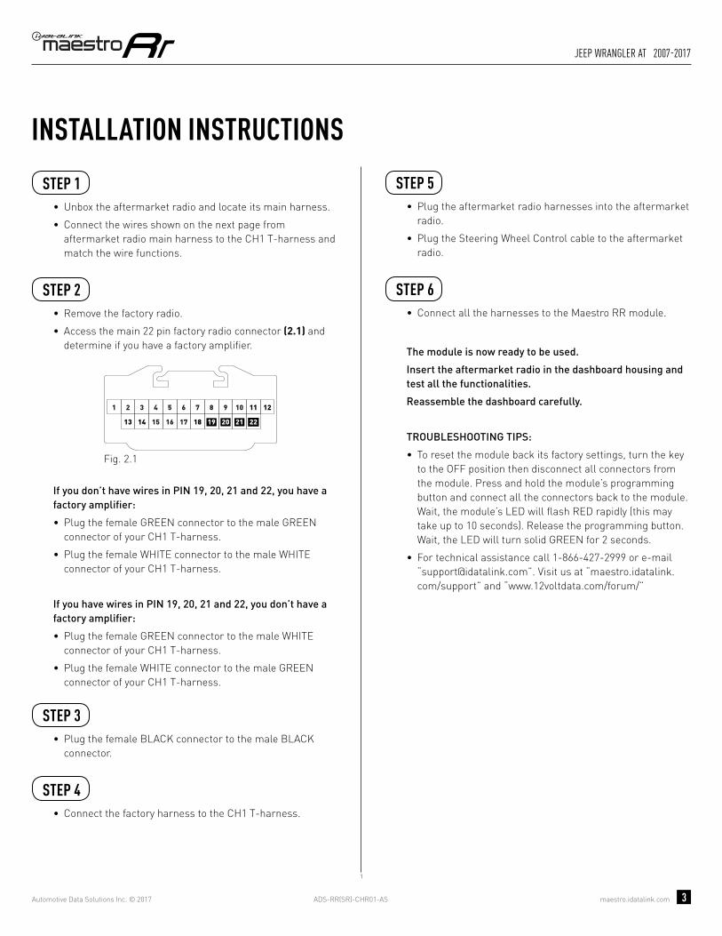
ADS-RR(SR)-CHR01-AS maestro.idatalink.com
Jeep wrangler at 2007-2017
Automotive Data Solutions Inc. © 2017 3
INSTALLATION INSTRUCTIONS STEP 1
• Unbox the aftermarket radio and locate its main harness.
• Connect the wires shown on the next page from aftermarket radio main harness to the CH1 T-harness and match the wire functions.
STEP 2
• Remove the factory radio.
• Access the main 22 pin factory radio connector (2.1) and determine if you have a factory amplifi er.
If you don’t have wires in PIN 19, 20, 21 and 22, you have a factory amplifi er:
• Plug the female GREEN connector to the male GREEN connector of your CH1 T-harness.
• Plug the female WHITE connector to the male WHITE connector of your CH1 T-harness.
If you have wires in PIN 19, 20, 21 and 22, you don’t have a factory amplifi er:
• Plug the female GREEN connector to the male WHITE connector of your CH1 T-harness.
• Plug the female WHITE connector to the male GREEN connector of your CH1 T-harness.
STEP 3• Plug the female BLACK connector to the male BLACK
connector.
STEP 4• Connect the factory harness to the CH1 T-harness.
STEP 5• Plug the aftermarket radio harnesses into the aftermarket
radio.
• Plug the Steering Wheel Control cable to the aftermarket radio.
STEP 6• Connect all the harnesses to the Maestro RR module.
The module is now ready to be used.
Insert the aftermarket radio in the dashboard housing and test all the functionalities.
Reassemble the dashboard carefully.
TROUBLESHOOTING TIPS:
• To reset the module back its factory settings, turn the key to the OFF position then disconnect all connectors from the module. Press and hold the module’s programming button and connect all the connectors back to the module. Wait, the module’s LED will fl ash RED rapidly (this may take up to 10 seconds). Release the programming button. Wait, the LED will turn solid GREEN for 2 seconds.
• For technical assistance call 1-866-427-2999 or e-mail “[email protected]”. Visit us at “maestro.idatalink.com/support” and “www.12voltdata.com/forum/”
87651 109
19181716
432
151413 21
11 12
2220
Fig. 2.1
1

ADS-RR(SR)-CHR01-AS maestro.idatalink.com
Jeep wrangler at 2007-2017
Automotive Data Solutions Inc. © 2017 4
C
A FG
C
A
G
F
1
E
E
WIRING DIAGRAMSTEP 1
STEP 2
STEP 3
STEP 4
STEP 5
STEP 6
MAESTRO RR MODULE
WHITE - LF SPEAKER (+)WHITE/BLACK - LF SPEAKER (-)GRAY - RF SPEAKER (+)GRAY/BLACK - RF SPEAKER (-)GREEN - LR SPEAKER (+)GREEN/BLACK - LR SPEAKER (-)
PURPLE/BLACK - RR SPEAKER (-)
YELLOW - 12V (+)
BLACK - GROUNDRED - ACCESSORY (+)
GREEN WHITE
WHITE GREEN
CONNECTIONS WITHOUT AMP
CONNECTIONS WITH AMP
ORANGE - ILLUMINATION (+)PURPLE/WHITE - REVERSE LIGHT (+) (*1)LTGREEN - E-BRAKE (-)
BLUE/WHITE - AMP. TURN ON (+)
MAINHARNESS
PURPLE - RR SPEAKER (+)
CONNECT TOAFTERMARKET RADIO
CH1 T-HARNESS
FACTORY RADIOHARNESS
RED/BROWN (NC)YELLOW/BROWN (NC)
WIRES FROMVEHICLE
PINK - VEHICLE SPEED (CONNECT IF THERE IS A MATCH)
GREEN GREEN
WHITEWHITE
BLACKBLACK
STEERING WHEELCONTROL CABLE
RED (NC)
BROWN - MUTE (-)

OPTIONAL ACCESSORIESADS-HRN(AV)-CHR01
PROGRAMMED FIRMWAREADS-RR(SR)-CHR01-AS
PRODUCTS REQUIREDiDatalink Maestro RR Radio Replacement InterfaceiDatalink Maestro CH1 Installation Harness
INSTALL GUIDEJEEP WRANGLER MT
2007-2017retains steering wheel controls and more!
NOTICE: Automotive Data Solutions Inc. (ADS) recommends having this installation performed by a certified technician. Logos and trademarks used here in are the properties of their respective owners.

ADS-RR(SR)-CHR01-AS maestro.idatalink.com
Jeep wrangler mt 2007-2017
Automotive Data Solutions Inc. © 2017 2
WELCOME
NEED hELP?
Congratulations on the purchase of your iDatalink Maestro RR Radio replacement solution. You are now a few simple steps away from enjoying your new car radio with enhanced features. Before starting your installation, please ensure that your iDatalink Maestro module is programmed with the correct fi rmware for your vehicle as per the Getting Started section, and that you carefully review the Installation Diagram and Vehicle Wire Reference Chart.
Please note that Maestro RR will only retain functionalities that were originally available in the vehicle.
1 866 427-2999
maestro.idatalink.com/supportwww.12voltdata.com/forum
DURING INSTALLATION
Installation Instructions 3
Wiring Diagram 4

ADS-RR(SR)-CHR01-AS maestro.idatalink.com
Jeep wrangler mt 2007-2017
Automotive Data Solutions Inc. © 2017 3
INSTALLATION INSTRUCTIONS STEP 1
• Unbox the aftermarket radio and locate its main harness.
• Connect the wires shown on the next page from aftermarket radio main harness to the CH1 T-harness and match the wire functions.
STEP 2
• Remove the factory radio.
• Access the main 22 pin factory radio connector (2.1) and determine if you have a factory amplifi er.
If you don’t have wires in PIN 19, 20, 21 and 22, you have a factory amplifi er:
• Plug the female GREEN connector to the male GREEN connector of your CH1 T-harness.
• Plug the female WHITE connector to the male WHITE connector of your CH1 T-harness.
If you have wires in PIN 19, 20, 21 and 22, you don’t have a factory amplifi er:
• Plug the female GREEN connector to the male WHITE connector of your CH1 T-harness.
• Plug the female WHITE connector to the male GREEN connector of your CH1 T-harness.
STEP 3• Plug the female BLACK connector to the male BLACK
connector.
STEP 4• Connect the factory harness to the CH1 T-harness.
STEP 5• Plug the aftermarket radio harnesses into the aftermarket
radio.
• Plug the Steering Wheel Control cable to the aftermarket radio.
STEP 6• To connect reverse camera, connect PURPLE/WHITE
Reverse Light (+) wire from aftermarket radio to White/Gray wire in harness in passenger kick panel.
STEP 7• Connect all the harnesses to the Maestro RR module.
The module is now ready to be used.
Insert the aftermarket radio in the dashboard housing and test all the functionalities.
Reassemble the dashboard carefully.
TROUBLESHOOTING TIPS:
• To reset the module back its factory settings, turn the key to the OFF position then disconnect all connectors from the module. Press and hold the module’s programming button and connect all the connectors back to the module. Wait, the module’s LED will fl ash RED rapidly (this may take up to 10 seconds). Release the programming button. Wait, the LED will turn solid GREEN for 2 seconds.
• For technical assistance call 1-866-427-2999 or e-mail “[email protected]”. Visit us at “maestro.idatalink.com/support” and “www.12voltdata.com/forum/”
87651 109
19181716
432
151413 21
11 12
2220
Fig. 2.1
3
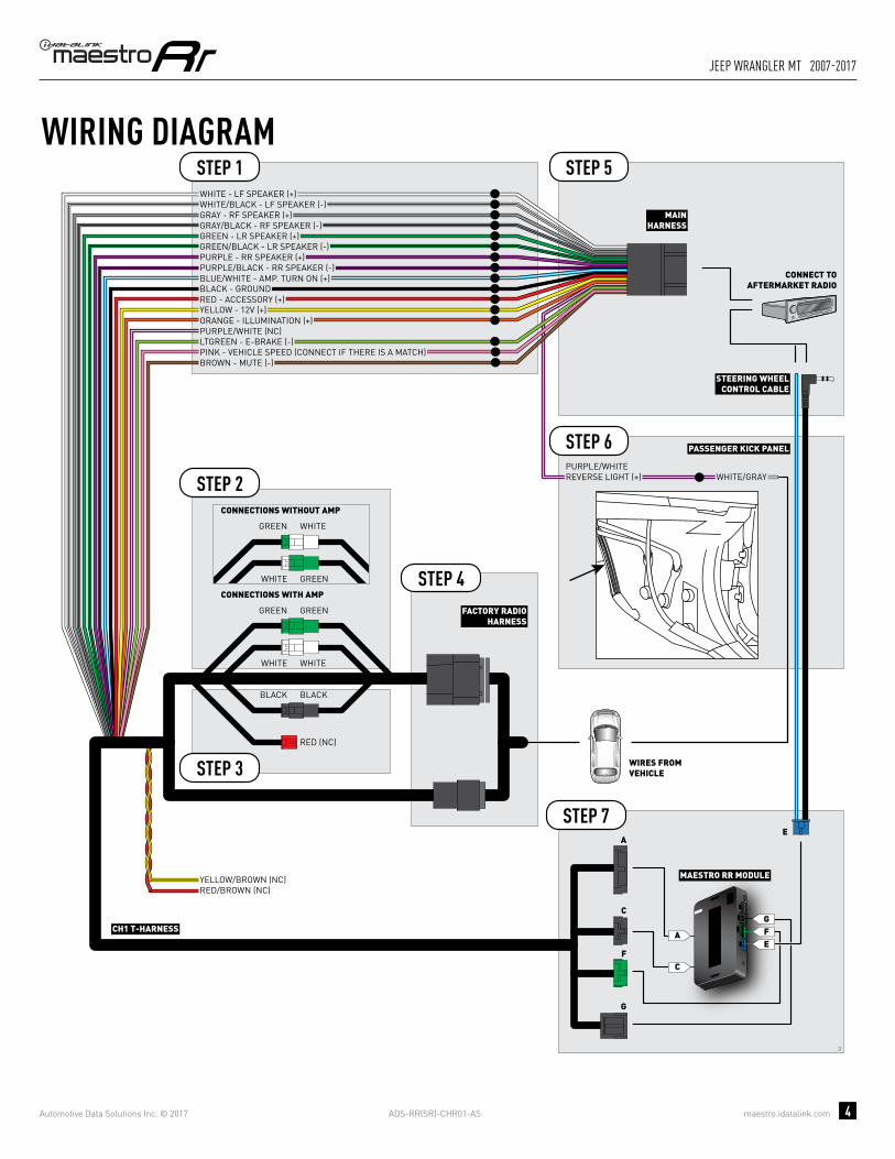
ADS-RR(SR)-CHR01-AS maestro.idatalink.com
Jeep wrangler mt 2007-2017
Automotive Data Solutions Inc. © 2017 4
C
A FG
C
A
G
F
3
E
E
WIRING DIAGRAMSTEP 1
STEP 2
STEP 3
STEP 4
STEP 5
STEP 6
STEP 7
MAESTRO RR MODULE
WHITE - LF SPEAKER (+)WHITE/BLACK - LF SPEAKER (-)GRAY - RF SPEAKER (+)GRAY/BLACK - RF SPEAKER (-)GREEN - LR SPEAKER (+)GREEN/BLACK - LR SPEAKER (-)
PURPLE/BLACK - RR SPEAKER (-)
YELLOW - 12V (+)
BLACK - GROUNDRED - ACCESSORY (+)
GREEN WHITE
WHITE GREEN
CONNECTIONS WITHOUT AMP
CONNECTIONS WITH AMP
ORANGE - ILLUMINATION (+)PURPLE/WHITE (NC)
PURPLE/WHITEREVERSE LIGHT (+) WHITE/GRAY
LTGREEN - E-BRAKE (-)
BLUE/WHITE - AMP. TURN ON (+)
MAINHARNESS
PURPLE - RR SPEAKER (+)
CONNECT TOAFTERMARKET RADIO
CH1 T-HARNESS
FACTORY RADIOHARNESS
RED/BROWN (NC)YELLOW/BROWN (NC)
WIRES FROMVEHICLE
PINK - VEHICLE SPEED (CONNECT IF THERE IS A MATCH)
GREEN GREEN
WHITEWHITE
BLACKBLACK
STEERING WHEELCONTROL CABLE
PASSENGER KICK PANEL
RED (NC)
BROWN - MUTE (-)

OPTIONAL ACCESSORIESADS-HRN(AV)-CHR01
PROGRAMMED FIRMWAREADS-RR(SR)-CHR01-AS
PRODUCTS REQUIREDiDatalink Maestro RR Radio Replacement InterfaceiDatalink Maestro CH1 Installation Harness
INSTALL GUIDEMITSUbIShI RAIDER
2008-2009retains steering wheel controls and more!
NOTICE: Automotive Data Solutions Inc. (ADS) recommends having this installation performed by a certified technician. Logos and trademarks used here in are the properties of their respective owners.

ADS-RR(SR)-CHR01-AS maestro.idatalink.com
mitsubishi raider 2008-2009
Automotive Data Solutions Inc. © 2017 2
WELCOME
NEED hELP?
Congratulations on the purchase of your iDatalink Maestro RR Radio replacement solution. You are now a few simple steps away from enjoying your new car radio with enhanced features. Before starting your installation, please ensure that your iDatalink Maestro module is programmed with the correct fi rmware for your vehicle as per the Getting Started section, and that you carefully review the Installation Diagram and Vehicle Wire Reference Chart.
Please note that Maestro RR will only retain functionalities that were originally available in the vehicle.
1 866 427-2999
maestro.idatalink.com/supportwww.12voltdata.com/forum
DURING INSTALLATION
Installation Instructions 3
Wiring Diagram 4

ADS-RR(SR)-CHR01-AS maestro.idatalink.com
mitsubishi raider 2008-2009
Automotive Data Solutions Inc. © 2017 3
INSTALLATION INSTRUCTIONS STEP 1
• Unbox the aftermarket radio and locate its main harness.
• Connect the wires shown on the next page from aftermarket radio main harness to the CH1 T-harness and match the wire functions.
STEP 2
• Remove the factory radio.
• Access the main 22 pin factory radio connector (2.1) and determine if you have a factory amplifi er.
If you don’t have wires in PIN 19, 20, 21 and 22, you have a factory amplifi er:
• Plug the female GREEN connector to the male GREEN connector of your CH1 T-harness.
• Plug the female WHITE connector to the male WHITE connector of your CH1 T-harness.
If you have wires in PIN 19, 20, 21 and 22, you don’t have a factory amplifi er:
• Plug the female GREEN connector to the male WHITE connector of your CH1 T-harness.
• Plug the female WHITE connector to the male GREEN connector of your CH1 T-harness.
STEP 3• Plug the female RED connector to the male BLACK
connector.
STEP 4• Connect the factory harness to the CH1 T-harness.
STEP 5• Plug the aftermarket radio harnesses into the aftermarket
radio.
• Plug the Steering Wheel Control cable to the aftermarket radio.
STEP 6• Connect all the harnesses to the Maestro RR module.
The module is now ready to be used.
Insert the aftermarket radio in the dashboard housing and test all the functionalities.
Reassemble the dashboard carefully.
TROUBLESHOOTING TIPS:
• To reset the module back its factory settings, turn the key to the OFF position then disconnect all connectors from the module. Press and hold the module’s programming button and connect all the connectors back to the module. Wait, the module’s LED will fl ash RED rapidly (this may take up to 10 seconds). Release the programming button. Wait, the LED will turn solid GREEN for 2 seconds.
• For technical assistance call 1-866-427-2999 or e-mail “[email protected]”. Visit us at “maestro.idatalink.com/support” and “www.12voltdata.com/forum/”
87651 109
19181716
432
151413 21
11 12
2220
Fig. 2.1
2

ADS-RR(SR)-CHR01-AS maestro.idatalink.com
mitsubishi raider 2008-2009
Automotive Data Solutions Inc. © 2017 4
C
A FG
C
A
G
F
2
E
E
BROWN - MUTE (-)
WIRING DIAGRAMSTEP 1
STEP 2
STEP 3
STEP 4
STEP 5
STEP 6
MAESTRO RR MODULE
WHITE - LF SPEAKER (+)WHITE/BLACK - LF SPEAKER (-)GRAY - RF SPEAKER (+)GRAY/BLACK - RF SPEAKER (-)GREEN - LR SPEAKER (+)GREEN/BLACK - LR SPEAKER (-)
PURPLE/BLACK - RR SPEAKER (-)
YELLOW - 12V (+)
BLACK - GROUNDRED - ACCESSORY (+)
GREEN WHITE
WHITE GREEN
CONNECTIONS WITHOUT AMP
CONNECTIONS WITH AMP
ORANGE - ILLUMINATION (+)PURPLE/WHITE - REVERSE LIGHT (+)LTGREEN - E-BRAKE (-)
BLUE/WHITE - AMP. TURN ON (+)
MAINHARNESS
PURPLE - RR SPEAKER (+)
CONNECT TOAFTERMARKET RADIO
CH1 T-HARNESS
FACTORY RADIOHARNESS
RED/BROWN (NC)YELLOW/BROWN (NC)
WIRES FROMVEHICLE
PINK - VEHICLE SPEED (CONNECT IF THERE IS A MATCH)
GREEN GREEN
WHITEWHITE
BLACKRED
BLACK (NC)
STEERING WHEELCONTROL CABLE

OPTIONAL ACCESSORIESADS-HRN(AV)-CHR01
PROGRAMMED FIRMWAREADS-RR(SR)-CHR01-AS
PRODUCTS REQUIREDiDatalink Maestro RR Radio Replacement InterfaceiDatalink Maestro CH1 Installation Harness
INSTALL GUIDERAM PICkUP 2009-2012
retains steering wheel controls and more!
NOTICE: Automotive Data Solutions Inc. (ADS) recommends having this installation performed by a certified technician. Logos and trademarks used here in are the properties of their respective owners.

ADS-RR(SR)-CHR01-AS maestro.idatalink.com
ram pickup 2009-2012
Automotive Data Solutions Inc. © 2017 2
WELCOME
NEED hELP?
Congratulations on the purchase of your iDatalink Maestro RR Radio replacement solution. You are now a few simple steps away from enjoying your new car radio with enhanced features. Before starting your installation, please ensure that your iDatalink Maestro module is programmed with the correct fi rmware for your vehicle as per the Getting Started section, and that you carefully review the Installation Diagram and Vehicle Wire Reference Chart.
Please note that Maestro RR will only retain functionalities that were originally available in the vehicle.
1 866 427-2999
maestro.idatalink.com/supportwww.12voltdata.com/forum
DURING INSTALLATION
Installation Instructions 3
Wiring Diagram 4

ADS-RR(SR)-CHR01-AS maestro.idatalink.com
ram pickup 2009-2012
Automotive Data Solutions Inc. © 2017 3
INSTALLATION INSTRUCTIONS STEP 1
• Unbox the aftermarket radio and locate its main harness.
• Connect the wires shown on the next page from aftermarket radio main harness to the CH1 T-harness and match the wire functions.
STEP 2
• Remove the factory radio.
• Access the main 22 pin factory radio connector (2.1) and determine if you have a factory amplifi er.
If you don’t have wires in PIN 19, 20, 21 and 22, you have a factory amplifi er:
• Plug the female GREEN connector to the male GREEN connector of your CH1 T-harness.
• Plug the female WHITE connector to the male WHITE connector of your CH1 T-harness.
If you have wires in PIN 19, 20, 21 and 22, you don’t have a factory amplifi er:
• Plug the female GREEN connector to the male WHITE connector of your CH1 T-harness.
• Plug the female WHITE connector to the male GREEN connector of your CH1 T-harness.
STEP 3• Plug the female BLACK connector to the male BLACK
connector.
STEP 4• Connect the factory harness to the CH1 T-harness.
STEP 5• Plug the aftermarket radio harnesses into the aftermarket
radio.
• Plug the Steering Wheel Control cable to the aftermarket radio.
STEP 6• Connect all the harnesses to the Maestro RR module.
The module is now ready to be used.
Insert the aftermarket radio in the dashboard housing and test all the functionalities.
Reassemble the dashboard carefully.
TROUBLESHOOTING TIPS:
• To reset the module back its factory settings, turn the key to the OFF position then disconnect all connectors from the module. Press and hold the module’s programming button and connect all the connectors back to the module. Wait, the module’s LED will fl ash RED rapidly (this may take up to 10 seconds). Release the programming button. Wait, the LED will turn solid GREEN for 2 seconds.
• For technical assistance call 1-866-427-2999 or e-mail “[email protected]”. Visit us at “maestro.idatalink.com/support” and “www.12voltdata.com/forum/”
87651 109
19181716
432
151413 21
11 12
2220
Fig. 2.1
1

ADS-RR(SR)-CHR01-AS maestro.idatalink.com
ram pickup 2009-2012
Automotive Data Solutions Inc. © 2017 4
C
A FG
C
A
G
F
1
E
E
WIRING DIAGRAMSTEP 1
STEP 2
STEP 3
STEP 4
STEP 5
STEP 6
MAESTRO RR MODULE
WHITE - LF SPEAKER (+)WHITE/BLACK - LF SPEAKER (-)GRAY - RF SPEAKER (+)GRAY/BLACK - RF SPEAKER (-)GREEN - LR SPEAKER (+)GREEN/BLACK - LR SPEAKER (-)
PURPLE/BLACK - RR SPEAKER (-)
YELLOW - 12V (+)
BLACK - GROUNDRED - ACCESSORY (+)
GREEN WHITE
WHITE GREEN
CONNECTIONS WITHOUT AMP
CONNECTIONS WITH AMP
ORANGE - ILLUMINATION (+)PURPLE/WHITE - REVERSE LIGHT (+) (*1)LTGREEN - E-BRAKE (-)
BLUE/WHITE - AMP. TURN ON (+)
MAINHARNESS
PURPLE - RR SPEAKER (+)
CONNECT TOAFTERMARKET RADIO
CH1 T-HARNESS
FACTORY RADIOHARNESS
RED/BROWN (NC)YELLOW/BROWN (NC)
WIRES FROMVEHICLE
PINK - VEHICLE SPEED (CONNECT IF THERE IS A MATCH)
GREEN GREEN
WHITEWHITE
BLACKBLACK
STEERING WHEELCONTROL CABLE
RED (NC)
BROWN - MUTE (-)

OPTIONAL ACCESSORIESADS-HRN(AV)-CHR01
PROGRAMMED FIRMWAREADS-RR(SR)-CHR01-AS
PRODUCTS REQUIREDiDatalink Maestro RR Radio Replacement InterfaceiDatalink Maestro CH1 Installation Harness
INSTALL GUIDEvOLkSWAGEN ROUTAN
2008-2011retains steering wheel controls and more!
NOTICE: Automotive Data Solutions Inc. (ADS) recommends having this installation performed by a certified technician. Logos and trademarks used here in are the properties of their respective owners.

ADS-RR(SR)-CHR01-AS maestro.idatalink.com
volkswagen routan 2008-2011
Automotive Data Solutions Inc. © 2017 2
WELCOME
NEED hELP?
Congratulations on the purchase of your iDatalink Maestro RR Radio replacement solution. You are now a few simple steps away from enjoying your new car radio with enhanced features. Before starting your installation, please ensure that your iDatalink Maestro module is programmed with the correct fi rmware for your vehicle as per the Getting Started section, and that you carefully review the Installation Diagram and Vehicle Wire Reference Chart.
Please note that Maestro RR will only retain functionalities that were originally available in the vehicle.
1 866 427-2999
maestro.idatalink.com/supportwww.12voltdata.com/forum
DURING INSTALLATION
Installation Instructions 3
Wiring Diagram 4

ADS-RR(SR)-CHR01-AS maestro.idatalink.com
volkswagen routan 2008-2011
Automotive Data Solutions Inc. © 2017 3
INSTALLATION INSTRUCTIONS STEP 1
• Unbox the aftermarket radio and locate its main harness.
• Connect the wires shown on the next page from aftermarket radio main harness to the CH1 T-harness and match the wire functions.
STEP 2
• Remove the factory radio.
• Access the main 22 pin factory radio connector (2.1) and determine if you have a factory amplifi er.
If you don’t have wires in PIN 19, 20, 21 and 22, you have a factory amplifi er:
• Plug the female GREEN connector to the male GREEN connector of your CH1 T-harness.
• Plug the female WHITE connector to the male WHITE connector of your CH1 T-harness.
If you have wires in PIN 19, 20, 21 and 22, you don’t have a factory amplifi er:
• Plug the female GREEN connector to the male WHITE connector of your CH1 T-harness.
• Plug the female WHITE connector to the male GREEN connector of your CH1 T-harness.
STEP 3• Plug the female BLACK connector to the male BLACK
connector.
STEP 4• Connect the factory harness to the CH1 T-harness.
STEP 5• Plug the aftermarket radio harnesses into the aftermarket
radio.
• Plug the Steering Wheel Control cable to the aftermarket radio.
STEP 6• Connect all the harnesses to the Maestro RR module.
The module is now ready to be used.
Insert the aftermarket radio in the dashboard housing and test all the functionalities.
Reassemble the dashboard carefully.
TROUBLESHOOTING TIPS:
• To reset the module back its factory settings, turn the key to the OFF position then disconnect all connectors from the module. Press and hold the module’s programming button and connect all the connectors back to the module. Wait, the module’s LED will fl ash RED rapidly (this may take up to 10 seconds). Release the programming button. Wait, the LED will turn solid GREEN for 2 seconds.
• For technical assistance call 1-866-427-2999 or e-mail “[email protected]”. Visit us at “maestro.idatalink.com/support” and “www.12voltdata.com/forum/”
87651 109
19181716
432
151413 21
11 12
2220
Fig. 2.1
1

ADS-RR(SR)-CHR01-AS maestro.idatalink.com
volkswagen routan 2008-2011
Automotive Data Solutions Inc. © 2017 4
C
A FG
C
A
G
F
1
E
E
WIRING DIAGRAMSTEP 1
STEP 2
STEP 3
STEP 4
STEP 5
STEP 6
MAESTRO RR MODULE
WHITE - LF SPEAKER (+)WHITE/BLACK - LF SPEAKER (-)GRAY - RF SPEAKER (+)GRAY/BLACK - RF SPEAKER (-)GREEN - LR SPEAKER (+)GREEN/BLACK - LR SPEAKER (-)
PURPLE/BLACK - RR SPEAKER (-)
YELLOW - 12V (+)
BLACK - GROUNDRED - ACCESSORY (+)
GREEN WHITE
WHITE GREEN
CONNECTIONS WITHOUT AMP
CONNECTIONS WITH AMP
ORANGE - ILLUMINATION (+)PURPLE/WHITE - REVERSE LIGHT (+) (*1)LTGREEN - E-BRAKE (-)
BLUE/WHITE - AMP. TURN ON (+)
MAINHARNESS
PURPLE - RR SPEAKER (+)
CONNECT TOAFTERMARKET RADIO
CH1 T-HARNESS
FACTORY RADIOHARNESS
RED/BROWN (NC)YELLOW/BROWN (NC)
WIRES FROMVEHICLE
PINK - VEHICLE SPEED (CONNECT IF THERE IS A MATCH)
GREEN GREEN
WHITEWHITE
BLACKBLACK
STEERING WHEELCONTROL CABLE
RED (NC)
BROWN - MUTE (-)

OPTIONAL ACCESSORIESADS-HRN(AV)-CHR01
PROGRAMMED FIRMWAREADS-RR(SR)-CHR01-AS
PRODUCTS REQUIREDiDatalink Maestro RR Radio Replacement InterfaceiDatalink Maestro CH1 Installation Harness
INSTALL GUIDEvOLkSWAGEN ROUTAN
2012-2014retains steering wheel controls and more!
NOTICE: Automotive Data Solutions Inc. (ADS) recommends having this installation performed by a certified technician. Logos and trademarks used here in are the properties of their respective owners.

ADS-RR(SR)-CHR01-AS maestro.idatalink.com
volkswagen routan 2012-2014
Automotive Data Solutions Inc. © 2017 2
WELCOME
NEED hELP?
Congratulations on the purchase of your iDatalink Maestro RR Radio replacement solution. You are now a few simple steps away from enjoying your new car radio with enhanced features. Before starting your installation, please ensure that your iDatalink Maestro module is programmed with the correct fi rmware for your vehicle as per the Getting Started section, and that you carefully review the Installation Diagram and Vehicle Wire Reference Chart.
Please note that Maestro RR will only retain functionalities that were originally available in the vehicle.
1 866 427-2999
maestro.idatalink.com/supportwww.12voltdata.com/forum
DURING INSTALLATION
Installation Instructions 3
Wiring Diagram 4

ADS-RR(SR)-CHR01-AS maestro.idatalink.com
volkswagen routan 2012-2014
Automotive Data Solutions Inc. © 2017 3
INSTALLATION INSTRUCTIONS STEP 1
• Unbox the aftermarket radio and locate its main harness.
• Connect the wires shown on the next page from aftermarket radio main harness to the CH1 T-harness and match the wire functions.
STEP 2
• Remove the factory radio.
• Access the main 22 pin factory radio connector (2.1) and determine if you have a factory amplifi er.
If you don’t have wires in PIN 19, 20, 21 and 22, you have a factory amplifi er:
• Plug the female GREEN connector to the male GREEN connector of your CH1 T-harness.
• Plug the female WHITE connector to the male WHITE connector of your CH1 T-harness.
If you have wires in PIN 19, 20, 21 and 22, you don’t have a factory amplifi er:
• Plug the female GREEN connector to the male WHITE connector of your CH1 T-harness.
• Plug the female WHITE connector to the male GREEN connector of your CH1 T-harness.
STEP 3• Plug the female BLACK connector to the male BLACK
connector.
STEP 4• Connect the factory harness to the CH1 T-harness.
STEP 5• Plug the aftermarket radio harnesses into the aftermarket
radio.
• Plug the Steering Wheel Control cable to the aftermarket radio.
STEP 6• Connect all the harnesses to the Maestro RR module.
The module is now ready to be used.
Insert the aftermarket radio in the dashboard housing and test all the functionalities.
Reassemble the dashboard carefully.
TROUBLESHOOTING TIPS:
• To reset the module back its factory settings, turn the key to the OFF position then disconnect all connectors from the module. Press and hold the module’s programming button and connect all the connectors back to the module. Wait, the module’s LED will fl ash RED rapidly (this may take up to 10 seconds). Release the programming button. Wait, the LED will turn solid GREEN for 2 seconds.
• For technical assistance call 1-866-427-2999 or e-mail “[email protected]”. Visit us at “maestro.idatalink.com/support” and “www.12voltdata.com/forum/”
87651 109
19181716
432
151413 21
11 12
2220
Fig. 2.1
1

ADS-RR(SR)-CHR01-AS maestro.idatalink.com
volkswagen routan 2012-2014
Automotive Data Solutions Inc. © 2017 4
C
A FG
C
A
G
F
1
E
E
WIRING DIAGRAMSTEP 1
STEP 2
STEP 3
STEP 4
STEP 5
STEP 6
MAESTRO RR MODULE
WHITE - LF SPEAKER (+)WHITE/BLACK - LF SPEAKER (-)GRAY - RF SPEAKER (+)GRAY/BLACK - RF SPEAKER (-)GREEN - LR SPEAKER (+)GREEN/BLACK - LR SPEAKER (-)
PURPLE/BLACK - RR SPEAKER (-)
YELLOW - 12V (+)
BLACK - GROUNDRED - ACCESSORY (+)
GREEN WHITE
WHITE GREEN
CONNECTIONS WITHOUT AMP
CONNECTIONS WITH AMP
ORANGE - ILLUMINATION (+)PURPLE/WHITE - REVERSE LIGHT (+) (*1)LTGREEN - E-BRAKE (-)
BLUE/WHITE - AMP. TURN ON (+)
MAINHARNESS
PURPLE - RR SPEAKER (+)
CONNECT TOAFTERMARKET RADIO
CH1 T-HARNESS
FACTORY RADIOHARNESS
RED/BROWN (NC)YELLOW/BROWN (NC)
WIRES FROMVEHICLE
PINK - VEHICLE SPEED (CONNECT IF THERE IS A MATCH)
GREEN GREEN
WHITEWHITE
BLACKBLACK
STEERING WHEELCONTROL CABLE
RED (NC)
BROWN - MUTE (-)