high precision dual-axis tracking solar wireless...
TRANSCRIPT
High precision dual-axis tracking solar wireless charging system based on the four quadrant photoelectric sensor
Zhilong Liu a,Biao Wang a,Weichao Tong a a School of Instrument Science and Opto-electronics Engineering, Hefei University of Technology,
Hefei 230009, China
ABSTRACT
This paper designs a solar automatic tracking wireless charging system based on the four quadrant photoelectric sensor. The system track the sun's rays automatically in real time to received the maximum energy and wireless charging to the load through electromagnetic coupling. Four quadrant photoelectric sensor responsive to the solar spectrum, the system could get the current azimuth and elevation angle of the light by calculating the solar energy incident on the sensor profile. System driver the solar panels by the biaxial movement mechanism to rotate and tilt movement until the battery plate and light perpendicular to each other. Maximize the use of solar energy, and does not require external power supply to achieve energy self-sufficiency. Solar energy can be collected for portable devices and load wireless charging by close electromagnetic field coupling. Experimental data show that: Four quadrant photoelectric sensor more sensitive to light angle measurement. when track positioning solar light, Azimuth deviation is less than 0.8 °, Elevation angle deviation is less than 0.6 °.Use efficiency of a conventional solar cell is only 10% -20%.The system uses a Four quadrant dual-axis tracking to raise the utilization rate of 25% -35%.Wireless charging electromagnetic coupling efficiency reached 60%.
Keywords: Four quadrant photoelectric sensor; Orientation angle of light; Solar energy utilization, Dual-axis tracking, Wireless charging
1. INTRODUCTION With the growing global energy issues, looking for new clean energy and alternative energy sources has become a common topic around the world. More and more people pay attention to solar energy because of its special characteristics such as clean, convenient and inexhaustible. In solar technology, the conversion efficiency of the solar cell panel study is the most important. There are a lot of ways to improve the conversion efficiency of solar panels such as use the single-axis tracking mode or dual-axis tracking mode. The highest conversion efficiency is the dual-axis tracking system, solar panels can rotate and tilt movement in real time, adjust their position to obtain maximum utilization of energy. This paper designed a dual axis solar tracking system based on the four-quadrant photoelectric sensor which improved the collection efficiency and the utilization efficiency of solar energy.
2. INTRODUCTION OF DUAL AXIS SOLAR TRACKING SYSTEM System consists of three parts: four-quadrant sensor module, mechanical support structure, energy acquisition and output. Main block diagram of the system is shown in Figure 1. Firstly, the four-quadrant photoelectric sensor can accurately detect the signal current inclination of the sun's rays. The main controller could get the current elevation angle and azimuth angles through AD sampling. Then, the main controller controls stepper motor driven mechanical structure. Solar panel moves to the direction perpendicular to the light to get the largest collection of energy.
2015 International Conference on Optical Instruments and Technology: Optoelectronic Measurement Technologyand Systems, edited by Jigui Zhu, Hwa-Yaw Tam, Kexin Xu, Hai Xiao, Sen Han, Proc. of SPIE Vol. 9623, 96230C
© 2015 SPIE · CCC code: 0277-786X/15/$18 · doi: 10.1117/12.2196377
Proc. of SPIE Vol. 9623 96230C-1

zoJsz bsus 13:S¿¿6_
I
cpsxßruß
ETscrzomse.
conbr ruß
tlnsqxsvt
'dmbITErsx
couqrt?ou
7F6bbGx Q¿sxrsl
scu.. c3rLUU2MI28TOL
bousx 14oqn_
dnsqzsuRfill2OL
Figure 1. Figure 1 show the main block diagram of the system
The main controller module uses the 16-bit microcontroller MC9S12XS128 from Freescale Semiconductor. Its built-in
12bit ADC,PWM modules and abundant IO resources satisfy the system design requirements. Stepper motor drive
module can output drive current up to 2A.,also satisfies the needs of the stepper motor drive. Inverter maximum output power is 1000W which could drive the general household loads. The effective charge distance is in less than 5cm when wireless charging. The control circuit design diagram shown in Figure 2.
Figure 2. Figure 2 show the main control circuit diagram
3. PRINCIPLE 3.1 Principle of the four-quadrant detector
The system uses BOS-S066A-type silicon light four-quadrant detector to detect the angle between the incident ray and the fixed normal. It can detect the light intensity within the four regions. Electro-optical characteristics of the sensor shown in Table 1:
Table 1. Four-quadrant sensor electro-optical characteristics
Item conditions Min. Typ. Max. Unit. Open circuit voltage Ev=100Lx
2856K 0.3 V
Short circuit current 9 µA Dark current VR=-1V 1 nA Terminal Capacitance V=1V,f=10KHz 50 pF Spectral sensitivity 40 100 nm Peak wavelength 940 nm
Proc. of SPIE Vol. 9623 96230C-2

dnsqLsgsgscqoL
riSPt
When installing the four-quadrant sensor, the sensor is placed at the bottom of a cylinder. Focus lens is placed on top of the opaque cylinder. Focusing lens focal length is 11mm. Lens focal length is less than the vertical height of the cylinder. When the light dipped into the cylinder, the bottom of the sensor area will produce a circular bright spots. The incident angle of light is different, bright spots in the area of the four quadrants will produce corresponding changes. Schematic diagram of the sensor installation shown in Figure 3:
Figure 3. Figure3 show the four-quadrant detector design
Four photosensitive area of the sensor can output four analog voltage. By detecting the ratio of the energy distribution of each quadrant can calculate the coordinates of the bright spots on the center position (a, b). The spatial position of the light can be calculated based on the coordinates. The basic formula is as follows: = (3.1) = (3.2)
In the formula, Ex and Ey respectively as x, y-axis offset. Sa, Sb, Sc, Sd is the distribution area of bright spot on four quadrants which can be obtained from the respective quadrant output voltage. Bright spot is set the center coordinates (a, b), We can draw that the angle between the incident ray in zox and zoy plane projection line normal to the flat plate φx and φy are: φx = arctan( )φy = arctan( ) (3.3)
The main controller calculating the height and azimuth of the incident light through sampling four quadrants’ voltage value successively. Then control a stepper motor driven movement of solar panels to the maximum power point.
3.2 Principle of tracking light
Commonly used optical tracking methods are gravity, electromagnetic and electric. These optical tracking methods using photodiodes work which has high sensitivity. There pursue sun trajectory methods, including single-axis and biaxial two kinds. This paper describes a typical dual-axis tracking system. Tracking system includes pitching motion and rotational motion. Pitch angle range is 0 degrees to 90 degrees. Rotation range is 0 degrees to 180 degrees. Dual-axis tracking dimensional mechanical structure is shown in Figure 4.
Proc. of SPIE Vol. 9623 96230C-3

2611201.
brFcpru
1110.f TC 111OFOz
Znbboz.r
Figure 4. Figure4 show the dual-axis tracking mechanical design
As can be seen from the figure, Four-quadrant sensor device in the top center of the solar panel and ensure the sensor plane parallel to the solar panels plane. Pitching motion mechanism includes worm movement mechanism and tripod agencies and the tripod institutions connected with solar panels. The whole mechanical linkage means on a common plate. Upper panel, pitching motion mechanism and a rotating motor shaft are all connected. The motor can drive the whole pitching rotation mechanism for rotating.
When the sun's rays and solar panels have a certain inclination, four quadrants will output four different voltage values. (Clockwise direction respectively defined as quadrant A, B, C, D.). The voltage data will transfer to the main controller by AD sampling module after through the amplifier and filter. Firstly, the main controller compares the numerical size of the (A + D) and (B + C). Then drive the rotary motion of the motor to make them approximately equal. Then compares the numerical size of the (A + B) and (C + D) and driving the pitch motor to make them substantially equal. Finally, the main controller obtained the angle values by calculation for precise positioning.
3.3 Energy storage and output
Energy will stored in the batteries through intelligent way after solar energy is collecting. The battery output the power through inverters and wireless charging module. The inverter circuit mainly consists of four parts: input filter circuit, boost circuit, full-bridge inverter circuit and the output of the filter circuit. The inverter function is to convert DC to AC. LC output filter circuit includes EMI filter circuit and circuit. The inverter circuit provides over-voltage protection, over-current protection and short circuit protection.
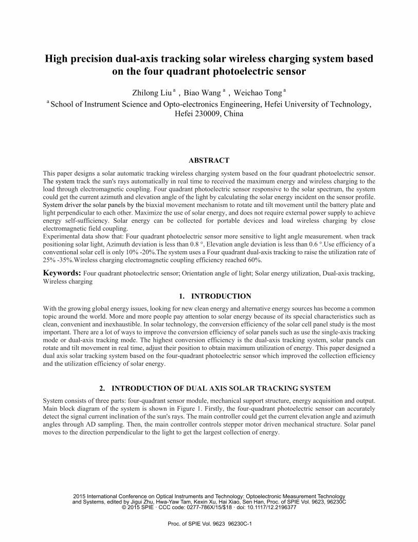
Wireless charging current domestic and international research is mainly divided into three types: electromagnetic induction charging, magnetic resonance charging, charging radio waves. These three methods have their advantages and disadvantages. Electromagnetic induction charging in a close distance but have the high charging efficiency. Therefore, this system uses wireless charging module coupled electromagnetic circuit. It consists of two parts: the primary circuit and the secondary circuit. The primary circuit converted the electrical energy into magnetic energy. Then, the secondary circuit will accept magnetic energy and transfer them to available power by AC-DC. Thus the system realized a non-contact power transmission. Wireless charging diagram is shown in Figure 5.
Proc. of SPIE Vol. 9623 96230C-4
_
\
nels
i
g transmit
\
uuu uuuiüriiiiiiiii
,.,,%,,,,,,1
\
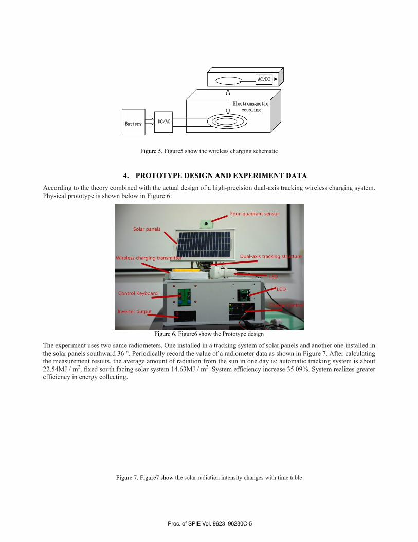
According to Physical prot
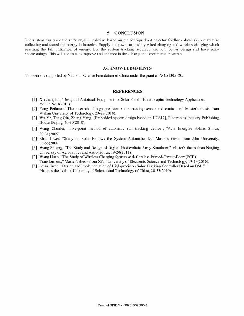
The experimethe solar panethe measurem22.54MJ / m2
efficiency in
the theory cootype is show
ent uses two sels southward
ment results, th2, fixed south energy collect
Battery
Figur
4. PROTombined with wn below in Fi
ame radiomet36 °. Periodic
he average amfacing solar sting.
Figure 7. Figur
DC/AC
re 5. Figure5 sh
TOTYPE Dthe actual des
igure 6:
Figure 6. Figu
ters. One instacally record th
mount of radiasystem 14.63M
re7 show the so
how the wireles
ESIGN ANDsign of a high-
ure6 show the Pr
alled in a trackhe value of a ration from theMJ / m2. Syste
olar radiation int
AC
Electromagnetcoupling
s charging sche
D EXPERIM-precision dua
rototype design
king system ofradiometer date sun in one daem efficiency
tensity changes
/DC
tic
ematic
MENT DATal-axis trackin
n
f solar panels ta as shown inay is: automatincrease 35.09
s with time table
TA ng wireless cha
and another on Figure 7. Aftic tracking sy9%. System re
e
arging system
one installed infter calculatingystem is abouealizes greater
m.
n g
ut r
Proc. of SPIE Vol. 9623 96230C-5
5. CONCLUSIONThe system can track the sun's rays in real-time based on the four-quadrant detector feedback data. Keep maximizecollecting and stored the energy in batteries. Supply the power to load by wired charging and wireless charging whichreaching the full utilization of energy. But the system tracking accuracy and low power design still have some shortcomings. This will continue to improve and enhance in the subsequent experimental research.
ACKNOWL
EDGMENTS This work is supported by National Science Foundation of China under the grant of NO.51305120.
REFERENCES
[1] Xia Jiangtao, “Design of Autotrack Equipment for Solar Panel,” Electro-optic Technology Application, Vol.25,No.1(2010).
[2] Yang Peihuan, “The research of high precision solar tracking sensor and controller,” Master's thesis from Wuhan University of Technology, 23-29(2010).
[3] Wu Ye, Teng Qin, Zhang Yang, [Embedded system design based on HCS12], Electronics Industry Publishing House,Beijing, 30-80(2010).
[4] Wang Chunlei, “Five-point method of automatic sun tracking device,”Acta Energiae Solaris Sinica,30-31(2005) .
[5] Zhao Liwei, “Study on Solar Follows the System Automatically,” Master's thesis from Jilin University,35-55(2006).
[6] Wang Shuang, “The Study and Design of Digital Photovoltaic Array Simulator,” Master's thesis from Nanjing University of Aeronautics and Astronautics, 19-20(2011).
[7] Wang Huan, “The Study of Wireless Charging System with Coreless Printed-Circuit-Board(PCB)Transformers,” Master's thesis from Xi'an University of Electronic Science and Technology, 19-28(2010).
[8] Guan Jiwen, “Design and Implementation of High-precision Solor Tracking Controller Based on DSP,”Master's thesis from University of Science and Technology of China, 20-33(2010).
Proc. of SPIE Vol. 9623 96230C-6