mtrack: high-precision passive tracking using millimeter...
TRANSCRIPT
mTrack: High-Precision Passive TrackingUsing Millimeter Wave Radios
Teng Wei and Xinyu ZhangDepartment of Electrical and Computer Engineering
University of Wisconsin - Madison
[email protected], [email protected]
ABSTRACTRadio-based passive-object sensing can enable a new form of per-vasive user-computer interface. Prior work has employed variouswireless signal features to sense objects under a set of predefined,coarse motion patterns. But an operational UI, like a trackpad, oftenneeds to identify fine-grained, arbitrary motion. This paper exploresthe feasibility of tracking a passive writing object (e.g., pen) at sub-centimeter precision. We approach this goal through a practicaldesign, mTrack, which uses highly-directional 60 GHz millimeter-wave radios as key enabling technology. mTrack runs a discretebeam scanning mechanism to pinpoint the object’s initial location,and tracks its trajectory using a signal-phase based model. In ad-dition, mTrack incorporates novel mechanisms to suppress inter-ference from background reflections, taking advantage of the shortwavelength of 60 GHz signals. We prototype mTrack and evaluateits performance on a 60 GHz reconfigurable radio platform. Exper-imental results demonstrate that mTrack can locate/track a pen with90-percentile error below 8 mm, enabling new applications such aswireless transcription and virtual trackpad.
Categories and Subject DescriptorsC.3 [Special-Purpose and Application-Based Systems]: Signalprocessing systems; H.5.2 [Information Interfaces and Presenta-tion]: User Interfaces—Input devices and strategies
Keywords60 GHz, Millimeter-wave, Tracking, Phase Shift, Background can-cellation
1. INTRODUCTIONRadio-based passive object sensing is a rapidly developing tech-
nology that detects the motion of human body parts or associatedobjects through wireless signals. Compared with conventional vision-based approaches [1], e.g., LeapMotion [2] and Kinect [3], it is lessintrusive and unaffected by ambient light conditions or the sunlightinterference. Catalyzed by the proliferation of mobile devices, thistechnology holds potential to enable new ubiquitous user-mobile in-
Permission to make digital or hard copies of all or part of this work for personal orclassroom use is granted without fee provided that copies are not made or distributedfor profit or commercial advantage and that copies bear this notice and the full citationon the first page. Copyrights for components of this work owned by others than theauthor(s) must be honored. Abstracting with credit is permitted. To copy otherwise, orrepublish, to post on servers or to redistribute to lists, requires prior specific permissionand/or a fee. Request permissions from [email protected]’15, September 7–11, 2015, Paris, France.Copyright is held by the owner/author(s). Publication rights licensed to ACM.ACM 978-1-4503-3619-2/15/09 ...$15.00.http://dx.doi.org/10.1145/2789168.2790113.
terfaces and spur a wide range of applications. The lastest passivesensing technology can already accurately distinguish a prescribedset of body/limb movement [4] based on Doppler patterns or sig-nal strength variation. Hand gesture sensing [5] is also achievableby training a pattern-matching model. To satisfy a broader rangeof applications, however, two design challenges remain open: fineresolution and unsupervised motion tracking.
We envision one such application scenario: tracking a writingobject (e.g., a stylus pen or marker) wirelessly. Conceptually, em-powered by multiple wireless devices, we can create an interactivetrackpad on any conventional surface, e.g., whiteboard or desktop.This way, we can deploy large touch screens in a more flexible andecomonic way than traditional graphic tablets. This vision entailstracking a small writing object with at least sub-centimeter preci-sion. Such precision has proven feasible in certain active RF sens-ing systems like Tagoram [6]. However, they are applicable only toobjects instrumented with an RFID tag or radio receiver.
In this paper, we design mTrack, which leverages 60 GHz mil-limeter wave (mmWave) radios to track the trajectory of a writ-ing object at high precision. 60 GHz radios are standardized inIEEE 802.11ad [7], and anticipated to penetrate one third of wire-less links by 2018 [8]. Commercial 802.11ad-capable smartphoneshave already been demonstrated [9]. Adopting mmWave insteadof conventional microwave band (2.4 GHz or 5 GHz) brings mul-tifold advantages. A shorter wavelength can create stronger reflec-tions from small objects (e.g., a pen), since wireless signals cannoteasily bypass objects larger than wavelength. More importantly,mmWave devices like 802.11ad allow for miniaturized phase-arraywith dozens of antenna elements, which together create highly-directional “pencil-beams”. Such directional beams are electron-ically steerable, thereby creating a new dimension for object local-ization/tracking.
mTrack’s design harnesses these unique advantages of mmWave.It uses one transmitter (Tx) to emit 60 GHz signals and illuminatea handhold object that roams on a trackpad area. Part of the sig-nals are diffused by the object’s surface and captured by two direc-tional receivers (Rx). mTrack leverages the received signal strength(RSS) and phase (relative to Tx) to localize and track the object.Simply put, by measuring the arriving direction of reflected sig-nals, each Rx can estimate the object’s relative angle, and pinpointits initial location on the trackpad. We refer to this as anchor pointacquisition (APA). When the object moves, the reflected signals’path length varies, which alters the phase, providing salient hintsfor tracking the object with sub-wavelength resolution. Our fea-sibility study using a 60 GHz software-radio (Section 3) verifiesthese principles, and unveils the unique advantage of mmWave pas-sive tracking over its microwave counterpart, in terms of potentialprecision, sensitivity to target size, etc. Yet in practical environ-
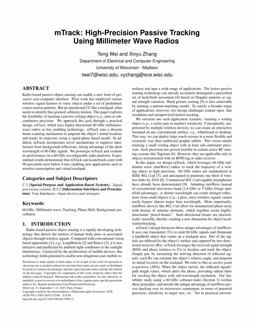
Properties Tagoram [6] RF-IDraw [10] Tomography [11, 12] WiVi [13] WiTrack [14] mTrackObject Type Active Active Passive Passive Passive Passive
Signal Feature Phase Phase RSS Phase RSS Phase/RSSMethodology Hologram Interferometry FP/AoA ISAR FMCW radar PS/BS
Track static object Yes Yes Yes No No Yes# of Tx&Rx ≥ 2 8 10 ∼ 100 ≥ 4 4 ≥ 3
Tracking Range 1 ∼ 10m 2 ∼ 5m 3m ∼ 20m 2 ∼ 7m 3 ∼ 9m 1mGranularity 14mm 49mm 80cm ∼ 3m 1m 30cm 8mm
Table 1: Comparison of different RF-based tracking systems. FP, PS and BS stand for fingerprint, phase shift and beam-steering.Data are from reported figures of cited works.
ment, these principles entail unique challenges, which we proposeto solve in mTrack.
First, reflected signals from irrelevant background objects canseverely distort the target-reflected signal and affect phase-trackingaccuracy. Prior passive tracking techniques use ultra-wideband [14],or measure and subtract static background reflection directly [15].In contrast, mTrack’s mmWave uses single-carrier phase-tracking,and needs to handle background dynamics. To meet this chal-lenge, we develop two algorithms: dual-differential background re-moval, and phase counting and regeneration, to recover the legit-imate phase change induced by target movement only. These twotechniques take unique advantage of short wavelength of mmWavesignals, and stay at different vantage points when considering atradeoff between tracking precision and resilience to the inherentphase noise in 60 GHz radios.
Second, although 60 GHz signals are commonly simplified aspseudo-optical [16], our measurement shows that they can be widelydiffused after hitting a small object. Thus, one cannot migratethe specular reflection effect in laser/infrared tracking systems [17]for 60 GHz tracking. In mTrack, we observe that 60 GHz an-tenna response bears a roll-off response pattern, and reflected RSSis strongest when the object direction matches the peak response.mTrack’s APA mechanism thus leverages steerable 60 GHz Rx an-tenna to find the matching point, and identify the object’s rela-tive angle. Since practical 60 GHz phase-array antennas can onlyswitch between a discrete set of directions, mTrack reconstructs theideal continuous scanning results from discrete sampling. Conse-quently, it can work even if the switching angle is much larger thanbeamwidth.
We have implemented mTrack on a custom-built 60 GHz software-radio platform. We evaluate mTrack’s APA and phase-tracking per-formance when user is navigating a pen over a 50cm×50cm virtualtrackpad region. Experimental results show that mTrack can local-ize the pen’s angular position with error less than 1◦, and track itsmotion trajectory with only 6 mm of median error and 8 mm of90-percentile error. We also found that mTrack can be readily usedto enable touch event detection (i.e., pen clicking/leaving the track-pad), owing to the constrained beam pattern of mmWave antennas.Using a simple feature-based detection algorithm, it achieves a de-tection accuracy of around 94%.
The main contributions of mTrack include the following:(i) A feasibility study of fine-grained, sub-centimeter scale ob-
ject localization/tracking using mmWave radios with steerable an-tennas, in contrast to microwave radios (Sec. 3).
(ii) A phase-based approach to track small objects like pens tohigh precision, thus realizing trackpad applications. The trackingscheme builds on two novel algorithms to counteract the impact ofbackground interference (Sec. 5).
(iii) A localization mechanism that leverages 60 GHz antennas topinpoint the object’s initial location and complement phase-trackingvia opportunistic calibration (Sec. 6).
(iv) Implementing mTrack on a reconfigurable 60 GHz radio testbed,and validating its localization/tracking performance in a practicalwireless trackpad setup (Sec. 8).
2. RELATED WORKRF-based Active Tracking. Localization of radio-equipped
objects has been explored extensively. RSS alone [18], or com-bined with phase [19], can serve as location signatures. But map-ping channel information to location usually requires site surveyand the accuracy is time and environment dependent [20]. In short-range, static environment, it is possible to locate a radio using apath-loss model (4cm error in an 1m2 area) [21]. However, forpassive tracking, RSS-model becomes inaccurate due to multipatheffects. Thus, mTrack only resorts to the variation of phase to re-alize passive tracking, which does not rely on any RSS-distancemodel.
Centimeter-scale RFID localization was achieved recently in RF-IDraw [10], which uses an interferometry technique to measurethe relative phase between multiple RFID readers. Tagoram [6]generates a phase hologram that statistically maps measured phaseto a potential position, and computes moving trajectory throughphase shifting. These tracking schemes require an RFID tag onthe object, which is not readily available for writing objects in dailyuse. To enable high precision passive tracking, mTrack faces twonew technical challenges unseen in [6, 10]. First, reflected signalfrom irrelevant background objects can severely distort the target-reflected signal and affect phase-tracking accuracy (more details inSection 5.2.2). Second, current 60 GHz radio hardware still hasnon-negligible phase noise, which contaminates the phase shifting.To meet these challenges, mTrack incorporates two novel process-ing techniques that recover legitimate phase change (Section 5). Inaddition, mTrack leverages the unique feature of beam steerabilityin 60 GHz radios to realize precise localization.
RF-based Passive Tracking. Passive object tracking is rem-iniscent of the vast literature in radar systems [14, 22]. Conven-tional radar, however, mainly focused on tracking large movingobjects using Doppler methods, and pushing the granularity us-ing wideband radios with GHz of sampling rate. mTrack, in con-trast, leverages single-carrier phased-based approach, taking advan-tage of electronically steerable 60 GHz antennas to track small ob-jects with sub-centimeter precision, thus enabling near-field inter-active applications like a trackpad. On the other hand, typical rang-ing radars require dedicated hardware, which is not readily avail-able in 60 GHz communication system. Pulse radar [23] needshigh-speed pulse generator while frequency-modulation continu-ous wave (FMCW) radar [14] requires a swiping carrier frequencycontrolled by VCO. On the contrary, mTrack’s single-carrier de-sign can be easily realized using 60 GHz communication hardware.Radar object tracking also faces interferences from background re-flection. However, mTrack’s mmWave phase-tracking method en-
-50
-40
-30
-20
-10
0
20 40 60 80 100 120 140Re
lative
RS
S (
dB
)
Rx view angle (deg.)
W/ pen W/o pen
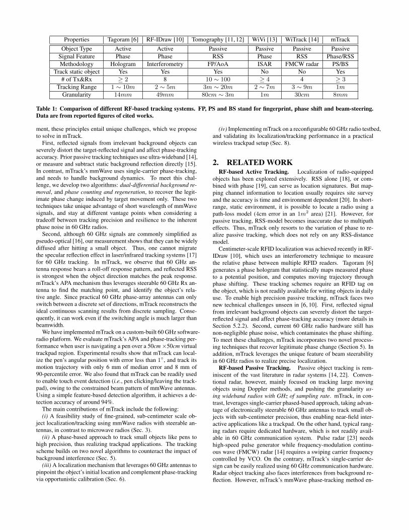
Figure 1: Small object (pen)causes diffusive 60 GHz signalsthat can be captured over dif-ferent view angles.
-3-2-1 0 1 2 3
500 520 540 560 580 600 0
50
100
150
200
250
Ph
ase
(ra
dia
ns)
Un
wra
p p
ha
se
(ra
d.)
X Coordinate (mm)
Pen Unwrap
(a)-3-2-1 0 1 2 3
500 520 540 560 580 600
Ph
ase
(ra
dia
ns)
X Coordinate (mm)
PenBottle
Can
(b)
Figure 2: Tracking under same 30◦ beamwidth (diameter: pen1.2cm, bottle 5.8cm and can 10.3cm). (a) Small object (pen) cancause [-π,π] phase variation in mmWave. (b) Microwave needs anobject (e.g. can) of size 9× larger.
-55-50-45-40-35-30-25-20
-20 -15 -10 -5 0 5 10 15 20Re
lative
RS
S (
dB
)
Steering Direction (deg.)
Figure 3: Beam steering to lo-cate target direction. Receivergets strong RSS when steering to-ward the target.
Tx
Rx
30cm
Angle to Tx [0°: 150°]
Pen 0.8cm
Tx
50cm
60cm
Moving
Tx
50cm
Rx
Rx
Beam-steering [−20°: 20°]
(a) Reflection
(b) Tracking (c) Locating
Figure 4: Setup of feasibility test. (a) Reflection test (Sec. 3.1):Rx centrally rotates around the target. (b) Tracking test (Sec. 3.2):Rx points to a moving target. (c) Locating test (Sec. 3.3): Rxsteers its beam toward various directions.
counters unique challenges that have not been addressed in exist-ing radar tracking algorithms [12, 14, 15, 24] (more details in Sec.5.2.2).
Radio tomography and imaging techniques [11,25] deploy a meshof sensors around sensing area and locate a person by identify-ing shadowed area that shows weak RSS or outstanding variation.mTrack is based on object reflection instead of blockage effect, andachieves a fine-grained tracking with much fewer sensing nodes.WiFi imaging (e.g., [26]) creates an image of sensing area throughan antenna array, though with a low resolution. WiFi RSS andDoppler metric have also been leveraged in gesture recognition [4,5], but the identification algorithm needs to be trained with knownpatterns. Besides tracking, millimeter wave has been used to inferobject’s surface curvature and material [27], which can be appliedto identify the target of interest.
To our knowledge, mTrack represents the first work that achievessub-centimeter scale passive object tracking, taking advantage ofthe small wavelength and steerable antennas of mmWave radios.Table 1 compares mTrack with other recent RF-based active andpassive tracking systems.
3. UNDERSTANDING MMWAVE PASSIVETRACKING
We first use our 60 GHz testbed to explore mmWave characteris-tics pertaining to high-precision passive object localization/tracking.Our experiments examine whether small writing objects can effec-tively reflect mmWave signals, and whether the reflected RSS/phasecan serve as subtle location/motion hints. The experiments also re-veal unique advantages of mmWave over 2.4 GHz microwave-bandsignals.
For a feasibility test, we create a simplified setup illustrated inFigure 4. Our testbed implementation is detailed in Section 8. Bydefault, the receiver antenna is placed at view angle 0◦ co-locatedwith the transmitter. Irrelevant reflections from background objectsare reduced by placing RF absorbers [28] (with approximately 35dB attenuation) near the boundary of testing region.
3.1 Reflection/Diffusion of Signals by ObjectsTo enable mmWave passive tracking, receiver must receive re-
flection signal from the target despite the view angle w.r.t. target.However, 60 GHz signals are often deemed to possess a pseudo-optical property. So, will they create mirror-like specular reflectionswhen hitting glossy objects? We examine the reflective property byrotating the receiver’s view angle around the location of the target– a stylus pen (0.4 cm radius) with a metal surface.
Figure 1 plots the average RSS of 100 measured values at eachview angle (with and without are abbreviated as w and w/). In thepresence of the pen, the RSS remains consistently high from viewangle 0◦ to 150◦, indicating that when reflecting 60 GHz signals,the target acts like a quasi-omni-directional antenna, rather than amirror. Thus, even a highly directional 60 GHz receiver can capturethe reflection from a wide range of view angles, as long as the targetis illuminated by the transmitter.
We also make two other observations. First, the transmitter’sbeamwidth determines the illumination coverage. 90◦ to 180◦ beam-width can ensure the target is illuminated as it moves across a wideregion in front of the transmitter. Second, even without target, theRSS varies, partly due to residual reflections from background, andpartly due to leakage signal from the transmitter especially at a wideview angle.
3.2 Phase Variation Enables Fine-Grained Mo-tion Tracking
Moving distance. Under ideal propagation/reflection, the phaseoffset between transmitter and receiver should only depend on thesignal path length (illumination plus reflection). Figure 2(a) showsthe phase variation as the target moves at 24 mm/second away fromthe transmitter/receiver. Owing to extremely short wavelength, i.e.,around 5 mm, even a small change of total signal path length canvary the phase significantly. By unwrapping [29] the phase value,we observe an increasing trend, indicating increasing path length, aconsequence of the target’s actual movement pattern. In addition,we see that the unwrapped phase value increases by 230 radians,translating to a distance 230
2π×0.25cm ≈ 9.15cm, roughly matching
the actual moving distance of 10 cm (Note that each phase cycle cor-responds to both illuminating and reflecting paths). In effect, whenzooming in one phase cycle, we can see that even sub-wavelengthmovement resolution is feasible.
These two observations hint that phase change of reflected sig-nals can indicate whether the target is moving towards/against the
Tx/Rx, and the relative moving distance. Small wavelength of 60GHz signals enables fine-grained distance resolution. However,two challenges remain open: (i) A single receiver cannot resolve thetarget’s moving angle within a 2D plane. (ii) Phase has an inherentaliasing effect, and cannot indicate the absolute location of target.This can be clearly observed from Figure 2(a), where phase exhibitscyclic behavior, with many locations sharing the same phase value.
It is worthy to note that the phase value experiences a jump be-tween 520ms and 540ms in Figure 2(a). This is caused by the sig-nals from background reflection — the RF absorber in our feasibil-ity test is not large enough to isolate all background objects. Ourphase processing techniques (Section 5) will remove such abnor-mality and guarantee the correctness of accumulated phase.
Target size. Electromagnetic waves can easily bypass aroundobstacles whose size is smaller than the wavelength, and will beblocked/reflected otherwise. Thus, we hypothesize that passive track-ing of small targets is a unique advantage of mmWave signals overmicrowave. To verify the hypothesis, we place a pair of 2.4 GHzsoftware radios following the same setup as above. Figure 2(b)plots the resulting phase variation as the target moves. For the sty-lus pen, the signal phase can hardly reach a full cycle of −π to π,and shows no clear correlation with wavelength. This is becausethe majority of the microwave signals bypass around the pen, witha radius much smaller than the wavelength (12.5 cm). Hence, back-ground reflections from afar tend to dominate and distort the phase.Only when the target (e.g., a can) size is sufficiently large can thereflected signals dominate and manifest full cyclic behavior as inthe mmWave case. This result confirms our hypothesis.
It is worth noting that mmWave signals may still suffer from dis-tortion under strong background reflection. This is a unique chal-lenge in comparison to tracking active objects (e.g., those instru-mented with RFID tags [6,10]), and will be investigated in mTrack.
3.3 Beam Steering Enables Localizing Abso-lute Position
Despite the wide diffusion angle of the object (Figure 1), a 60GHz receiver can have highly narrow beamwidth and will be ableto capture the diffused signals only when it is pointing to the tar-get. Figure 3 verifies this property. We steer the receiver’s pointingangle between −20◦ to 20◦, at 1◦ granularity. The measured RSSpeaks at around 0◦ when the receiver points towards the target. Thisindicates that we can take advantage of 60 GHz beams’ steerabilityto fix the target’s absolute angle relative to the Tx/Rx.
In practice, a 60 GHz antenna may not be steered continuously asin our experiment. In addition, the RSS may also suffer from back-ground reflection effect, which causes multipath effect and RSSvariation as shown in Figure 1. mTrack is designed to meet thesechallenges.
4. AN OVERVIEW OF mTrackmTrack builds on the foregoing measurement observations to re-
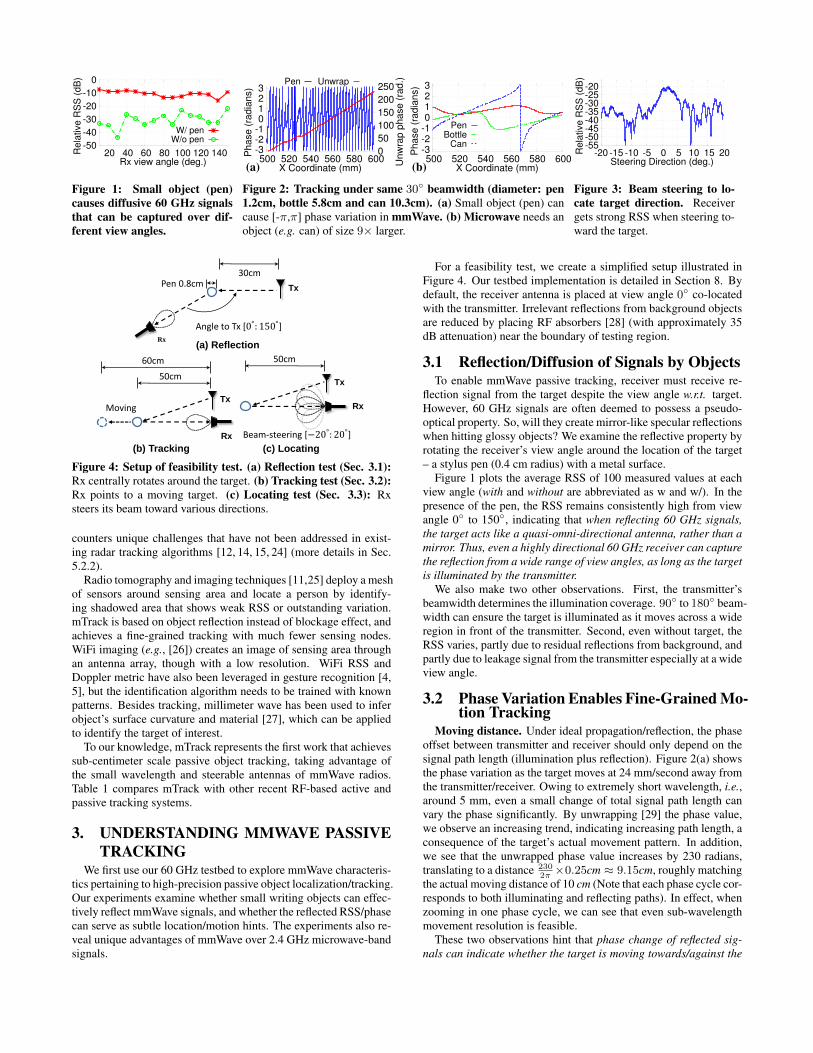
alize a high-precision mmWave trackpad. Figure 5 shows a typicalmTrack setup. One quasi-omni Tx and two directional Rx antennasare placed to form a right angle, and track an object within a rect-angular trackpad region (0 < x < 2a, 0 < y < 2b). a and b are setto 50 cm by default.
Both the quasi-omni and directional beam patterns can be readilygenerated via 802.11ad devices’ phased-array antennas [7,30]. Thequasi-omni transmitter beam in mTrack is used to illuminate thetrackpad area. Typical quasi-omni beamwidth in 60 GHz rangesfrom 20◦ to 180◦. The transmit signal is able to cover the trackingregion, without the need to adjust the transmitter’s beam directionfor scanning target. On the other hand, the Rx adopts highly direc-
x
y
(2a, b)oRx2
Rx1
o𝐷𝑡𝑅1
𝐷𝑡𝑅2
𝐷𝑡𝑇
(2a, 2b)
Tx
(a, 2b)
Figure 5: mTrack setup. Grayarea denotes tracking region.
RSS/phase
Extraction
Tracking
Locating
Clicking
AppsmTrack
Figure 6: mTrack system com-ponents and functionalities.
tional antennas, for two reasons. First, with a high antenna gain, itcan substantially boost signal quality, enabling mTrack to capturethe weak reflections from target. Second, a directional receiver canhelp isolate the leakage interference from the Tx, which may oth-erwise overwhelm the target-reflected signals. Using highly direc-tional antennas reduces the beams’ intersecting area. The receiverkeeps track of the target by adaptively steering the beam direction.The system detects target’s entrance and exit through the touch de-tection module (detailed in Section 7). It also knows when the targetstarts to move and the moving tendency by measuring the trend andamount of phase shifting (detailed in Section 5).
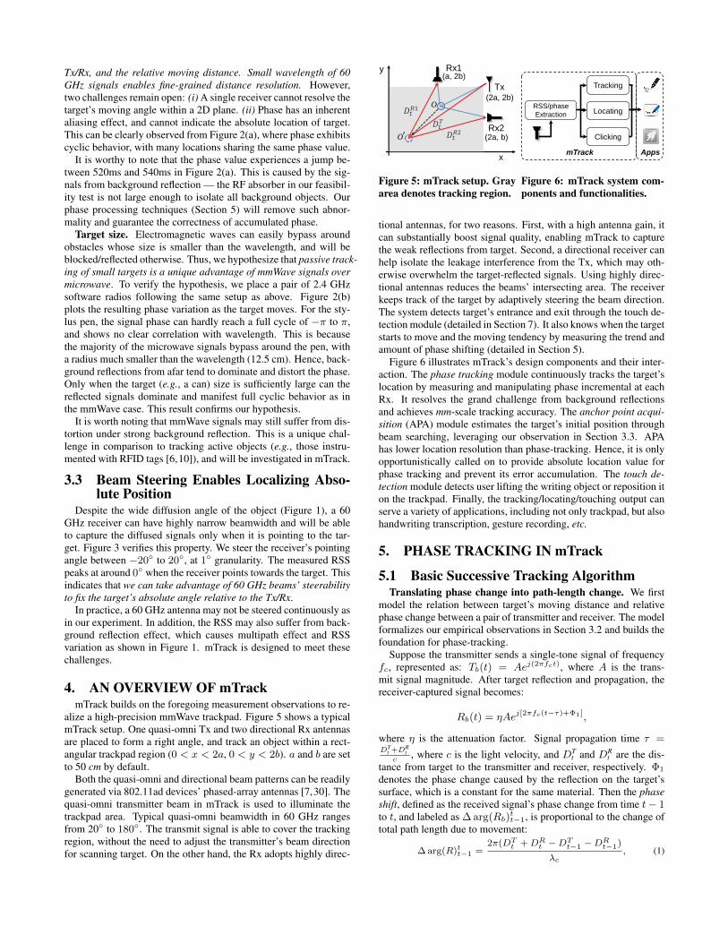
Figure 6 illustrates mTrack’s design components and their inter-action. The phase tracking module continuously tracks the target’slocation by measuring and manipulating phase incremental at eachRx. It resolves the grand challenge from background reflectionsand achieves mm-scale tracking accuracy. The anchor point acqui-sition (APA) module estimates the target’s initial position throughbeam searching, leveraging our observation in Section 3.3. APAhas lower location resolution than phase-tracking. Hence, it is onlyopportunistically called on to provide absolute location value forphase tracking and prevent its error accumulation. The touch de-tection module detects user lifting the writing object or reposition iton the trackpad. Finally, the tracking/locating/touching output canserve a variety of applications, including not only trackpad, but alsohandwriting transcription, gesture recording, etc.
5. PHASE TRACKING IN mTrack
5.1 Basic Successive Tracking AlgorithmTranslating phase change into path-length change. We first
model the relation between target’s moving distance and relativephase change between a pair of transmitter and receiver. The modelformalizes our empirical observations in Section 3.2 and builds thefoundation for phase-tracking.
Suppose the transmitter sends a single-tone signal of frequencyfc, represented as: Tb(t) = Aej(2πfct), where A is the trans-mit signal magnitude. After target reflection and propagation, thereceiver-captured signal becomes:
Rb(t) = ηAej[2πfc(t−τ)+Φ1],
where η is the attenuation factor. Signal propagation time τ =DT
t +DRt
c, where c is the light velocity, and DT
t and DRt are the dis-
tance from target to the transmitter and receiver, respectively. Φ1
denotes the phase change caused by the reflection on the target’ssurface, which is a constant for the same material. Then the phaseshift, defined as the received signal’s phase change from time t− 1to t, and labeled as ∆ arg(Rb)
tt−1, is proportional to the change of
total path length due to movement:
∆ arg(R)tt−1 =2π(DTt +DRt −DTt−1 −DRt−1)
λc, (1)
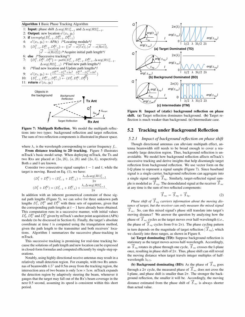
Algorithm 1 Basic Phase Tracking Algorithm1: Input: phase shift ∆ arg(R1)tt−1 and ∆ arg(R2)tt−1,2: Output: new location o′(xt, yt)3: if isempty(DT
t−1, DR1t−1, D
R2t−1)
4: o′(xt, yt)← APA() /*Locating module*/5: {DTt−1, D
R1t−1, D
R2t−1} ← {|
−→o′ −
−−−→o(Tx)|, |
−→o′ −
−−−−→o(Rx1)|,
|−→o′ −
−−−−→o(Rx2)|} /*Acquire initial path length*/
6: else /*Successive tracking*/7: {DTt , DR1
t , DR2t } ← path(DTt−1.D
R1t−1, D
R2t−1,∆ arg(R1)tt−1,
∆ arg(R2)tt−1) /*Find new path lengths*/8: /*Find new location and Update path lengths*/
9: o′(xt, yt)← (DR1
t2−DT
t2+3a2
2a,DR2
t2−DT
t2+3b2
2b)
10: {DTt−1, D
R1t−1, D
R2t−1} ← {DT
t , DR1t , D
R2t }
11: return o′(xt, yt)
Tx Ant
Rx Ant
I
Q𝑆bg
𝑆target
Background
Reflection
Target Reflection
Objects in
the background
Figure 7: Multipath Reflection. We model the multipath reflec-tions into two types: background reflection and target reflection.The sum of two reflection components is illustrated in phasor space.
where λc is the wavelength corresponding to carrier frequency fc.From distance tracking to 2D tracking. Figure 5 illustrates
mTrack’s basic model setup. When deploying mTrack, the Tx andtwo Rxs are placed at (2a, 2b), (a, 2b) and (2a, b), respectively.Both a and b are known.
Consider two consecutive signal samples t − 1 and t, while thetarget is moving. Based on Eq. (1), we have:
(DTt +DR1
t ) = (DTt−1 +DR1
t−1) +λc∆ arg(R1)tt−1
2π
(DTt +DR2
t ) = (DTt−1 +DR2
t−1) +λc∆ arg(R2)tt−1
2π.
In addition with an inherent geometrical constraint of those sig-nal path lengths (Figure 5), we can solve for three unknown pathlengths DT
t , DR1t and DR2
t with three sets of equations, given thatthe corresponding path-lengths at t−1 have already been obtained.This computation runs in a successive manner, with initial valuesDT
0,DR10 andDR2
0 given by mTrack’s anchor point acquisition (APA)module (to be discussed in Section 6). Finally, the target’s absolutecoordinate at time t is computed using the triangulation method,given the path length to the transmitter and both receivers’ loca-tions. Algorithm 1 summarizes the successive phase-tracking inmTrack.
This successive tracking is promising for real-time tracking be-cause the solutions of path length and new location can be expressedin closed-form formulas and computed efficiently by single-step op-erations.
Notably, using highly directional receive antennas may result in arelatively small detection region. For example, with two Rx anten-nas of beamwidth 4.5◦ and 0.5m away from the tracking region, theintersection area of two beams is only 5cm×5cm. mTrack expandsthe detection region by adaptively steering the beam, whenever itgauges that the target may fall out of the Rx’s beam coverage in thenext 0.5 second, assuming its speed is consistent within this shortperiod.
𝑆 trgarg( )
𝑆bgI
Q
𝑆trg
arg( )
arg( )𝑆 rec
𝑆 bg I
Q
arg( )𝑆 rec
𝑆 trgarg( )
I
Q
𝑆 bg
𝑆 trgarg( )
arg( )𝑆 rec
0
𝑆 trgarg( )0
2𝜋(λ)
arg( )𝑆 rec
λ/2 λ 3λ/2 2λ
2𝜋(λ)
arg( )𝑆 rec
0𝑆 trgarg( )
2𝜋(λ)
arg( )𝑆 rec
(a) Target Dominated (TD)
(b) Background Dominated (BD)
(c) Intermediate (ITM)
λ/2 λ 3λ/2 2λ
λ/2 λ 3λ/2 2λ
Figure 8: Impact of (static) background reflection on phaseshift. (a) Target reflection dominates background. (b) Target re-flection is much weaker than background. (c) Intermediate case.
5.2 Tracking under Background Reflection
5.2.1 Impact of background reflection on phase shiftThough directional antennas can alleviate multipath effect, an-
tenna beamwidth still needs to be broad enough to cover a rea-sonably large detection region. Thus, background reflection is un-avoidable. We model how background reflection affects mTrack’ssuccessive tracking and derive insights that help disentangle targetreflection from background reflection. We use vector form on theI-Q plane to represent a signal sample (Figure 7). Since basebandsignal is a single-carrier, background reflections can aggregate intoa single signal sample
−→S bg. Similarly, target-reflected signal sam-
ple is modeled as−→S trg. The demodulated signal at the receiver
−→S rec
at any time is the sum of two reflected components:−→S rec =
−→S trg +
−→S bg. (2)
Phase shift of−→S trg carriers information about the moving dis-
tance of target, but the receiver can only measure the mixed signal−→S rec. So, can this mixed signal’s phase still translate into target’s
moving distance? We answer the question by analyzing how thephase of
−→S rec cycles as the target moves over half-wavelength (i.e.,
the phase of−→S trg cycles from 0 to 2π). The phase cycling pattern
in turn depends on the magnitude of target reflection |−→S trg|, whichwe classify into three ranges, as shown in Figure 8.
(a) Target dominating (TD): Suppose background reflection isstationary as the target moves across half-wavelength. Accordingly,as−→S trg rotates its phase through one cycle,
−→S rec crosses the I-plane
once, resulting in phase shift of 2π. Thus, phase shift can still revealthe moving distance when target travels integer multiples of half-wavelength λ0.5.
(b) Background dominating (BD): As the phase of−→S trg goes
through a 2π cycle, the measured phase of−→S rec does not cross the
I-plane, and phase shift is smaller than 2π. The stronger the back-ground reflection, the smaller it will be. Accordingly, the movingdistance estimated from the phase shift of
−→S rec is always shorter
than actual value.
𝑆bg I
Q
𝑆 rec
t
Δ𝑎𝑟𝑔( )𝑡−1𝑡
𝑆 trg
𝑆 trg
t 𝑆 trg
t+1−
𝑆 trg
t-1 𝑆 trg
t−
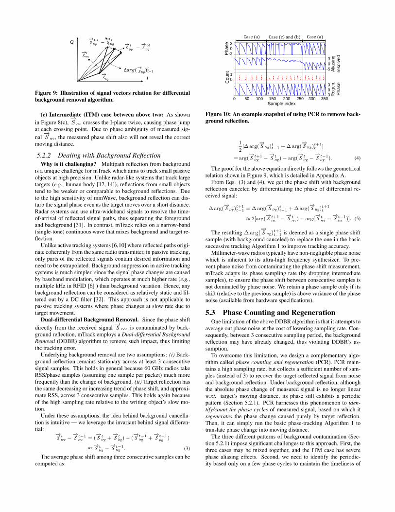
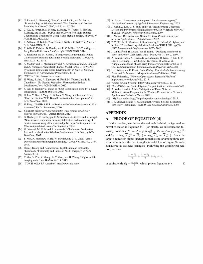
Figure 9: Illustration of signal vectors relation for differentialbackground removal algorithm.
(c) Intermediate (ITM) case between above two: As shownin Figure 8(c),
−→S rec crosses the I-plane twice, causing phase jump
at each crossing point. Due to phase ambiguity of measured sig-nal−→S rec, the measured phase shift also will not reveal the correct
moving distance.
5.2.2 Dealing with Background ReflectionWhy is it challenging? Multipath reflection from background
is a unique challenge for mTrack which aims to track small passiveobjects at high precision. Unlike radar-like systems that track largetargets (e.g., human body [12, 14]), reflections from small objectstend to be weaker or comparable to background reflections. Dueto the high sensitivity of mmWave, background reflection can dis-turb the signal phase even as the target moves over a short distance.Radar systems can use ultra-wideband signals to resolve the time-of-arrival of reflected signal paths, thus separating the foregroundand background [31]. In contrast, mTrack relies on a narrow-band(single-tone) continuous wave that mixes background and target re-flection.
Unlike active tracking systems [6,10] where reflected paths origi-nate coherently from the same radio transmitter, in passive tracking,only parts of the reflected signals contain desired information andneed to be extrapolated. Background suppression in active trackingsystems is much simpler, since the signal phase changes are causedby baseband modulation, which operates at much higher rate (e.g.,multiple kHz in RFID [6] ) than background variation. Hence, anybackground reflection can be considered as relatively static and fil-tered out by a DC filter [32]. This approach is not applicable topassive tracking systems where phase changes at slow rate due totarget movement.
Dual-differential Background Removal. Since the phase shiftdirectly from the received signal
−→S rec is contaminated by back-
ground reflection, mTrack employs a Dual-differential BackgroundRemoval (DDBR) algorithm to remove such impact, thus limitingthe tracking error.
Underlying background removal are two assumptions: (i) Back-ground reflection remains stationary across at least 3 consecutivesignal samples. This holds in general because 60 GHz radios takeRSS/phase samples (assuming one sample per packet) much morefrequently than the change of background. (ii) Target reflection hasthe same decreasing or increasing trend of phase shift, and approxi-mate RSS, across 3 consecutive samples. This holds again becauseof the high sampling rate relative to the writing object’s slow mo-tion.
Under these assumptions, the idea behind background cancella-tion is intuitive — we leverage the invariant behind signal differen-tial:
−→S trec −
−→S t−1
rec = (−→S ttrg +
−→S tbg)− (
−→S t−1
trg +−→S t−1
bg )
u−→S ttrg −
−→S t−1
trg . (3)
The average phase shift among three consecutive samples can becomputed as:
Ph
ase
Alia
sin
g
resolv
ed
Co
un
t
0 50 100 150 200 250 300 350
Re
ge
n.
Ph
ase
Case (a) Case c and (b) Case (a)
Sample index
3
0
-3
1
0
3
0
-3
3
0
-5
Figure 10: An example snapshot of using PCR to remove back-ground reflection.
1
2[∆ arg(
−→S trg)tt−1 + ∆ arg(
−→S trg)t+1
t ]
= arg(−→S t+1
trg −−→S ttrg)− arg(
−→S ttrg −
−→S t−1
trg ). (4)
The proof for the above equation directly follows the geometricalrelation shown in Figure 9, which is detailed in Appendix A.
From Eqs. (3) and (4), we get the phase shift with backgroundreflection canceled by differentiating the phase of differential re-ceived signal:
∆ arg(−→S trg)t+1
t−1 = ∆ arg(−→S trg)tt−1 + ∆ arg(
−→S trg)t+1
t
≈ 2[arg(−→S t+1
rec −−→S trec)− arg(
−→S trec −
−→S t−1
rec )]. (5)
The resulting ∆ arg(−→S trg)
t+1t−1 is deemed as a single phase shift
sample (with background canceled) to replace the one in the basicsuccessive tracking Algorithm 1 to improve tracking accuracy.
Millimeter-wave radios typically have non-negligible phase noisewhich is inherent to its ultra-high frequency synthesizer. To pre-vent phase noise from contaminating the phase shift measurement,mTrack adapts its phase sampling rate (by dropping intermediatesamples), to ensure the phase shift between consecutive samples isnot dominated by phase noise. We retain a phase sample only if itsshift (relative to the previous sample) is above variance of the phasenoise (available from hardware specifications).
5.3 Phase Counting and RegenerationOne limitation of the above DDBR algorithm is that it attempts to
average out phase noise at the cost of lowering sampling rate. Con-sequently, between 3 consecutive sampling period, the backgroundreflection may have already changed, thus violating DDBR’s as-sumption.
To overcome this limitation, we design a complementary algo-rithm called phase counting and regeneration (PCR). PCR main-tains a high sampling rate, but collects a sufficient number of sam-ples (instead of 3) to recover the target-reflected signal from noiseand background reflection. Under background reflection, althoughthe absolute phase change of measured signal is no longer linearw.r.t. target’s moving distance, its phase still exhibits a periodicpattern (Section 5.2.1). PCR harnesses this phenomenon to iden-tify/count the phase cycles of measured signal, based on which itregenerates the phase change caused purely by target reflection.Then, it can simply run the basic phase-tracking Algorithm 1 totranslate phase change into moving distance.
The three different patterns of background contamination (Sec-tion 5.2.1) impose significant challenges to this approach. First, thethree cases may be mixed together, and the ITM case has severephase aliasing effects. Second, we need to identify the periodic-ity based only on a few phase cycles to maintain the timeliness of
-45
-40
-35
-30
-25
-20
-15
10 20 30 40 50 60 70 80
RS
S (
dB
)
Direction (degrees)
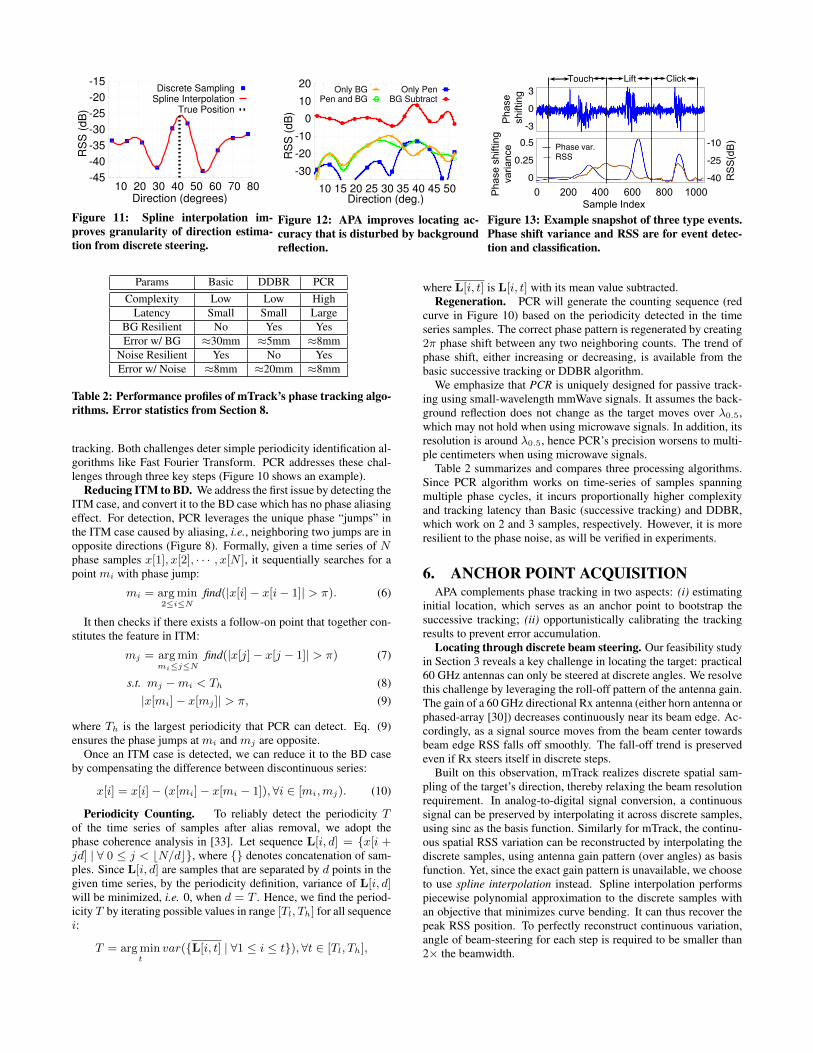
Discrete SamplingSpline Interpolation
True Position
Figure 11: Spline interpolation im-proves granularity of direction estima-tion from discrete steering.
-30
-20
-10
0
10
20
10 15 20 25 30 35 40 45 50
RS
S (
dB
)
Direction (deg.)
Only BGPen and BG
Only PenBG Subtract
Figure 12: APA improves locating ac-curacy that is disturbed by backgroundreflection.
Phas
esh
iftin
g
0 200 400 600 800 1000Sample Index
Phas
esh
iftin
gva
rianc
e
RSS
(dB)
RSSPhase var.
Touch Lift Click3
0-3
0.5
0.250
-10
-25-40
Figure 13: Example snapshot of three type events.Phase shift variance and RSS are for event detec-tion and classification.
Params Basic DDBR PCRComplexity Low Low High
Latency Small Small LargeBG Resilient No Yes YesError w/ BG ≈30mm ≈5mm ≈8mm
Noise Resilient Yes No YesError w/ Noise ≈8mm ≈20mm ≈8mm
Table 2: Performance profiles of mTrack’s phase tracking algo-rithms. Error statistics from Section 8.
tracking. Both challenges deter simple periodicity identification al-gorithms like Fast Fourier Transform. PCR addresses these chal-lenges through three key steps (Figure 10 shows an example).
Reducing ITM to BD. We address the first issue by detecting theITM case, and convert it to the BD case which has no phase aliasingeffect. For detection, PCR leverages the unique phase “jumps” inthe ITM case caused by aliasing, i.e., neighboring two jumps are inopposite directions (Figure 8). Formally, given a time series of Nphase samples x[1], x[2], · · · , x[N ], it sequentially searches for apoint mi with phase jump:
mi = arg min2≤i≤N
find(|x[i]− x[i− 1]| > π). (6)
It then checks if there exists a follow-on point that together con-stitutes the feature in ITM:
mj = arg minmi≤j≤N
find(|x[j]− x[j − 1]| > π) (7)
s.t. mj −mi < Th (8)|x[mi]− x[mj ]| > π, (9)
where Th is the largest periodicity that PCR can detect. Eq. (9)ensures the phase jumps at mi and mj are opposite.
Once an ITM case is detected, we can reduce it to the BD caseby compensating the difference between discontinuous series:
x[i] = x[i]− (x[mi]− x[mi − 1]),∀i ∈ [mi,mj). (10)
Periodicity Counting. To reliably detect the periodicity Tof the time series of samples after alias removal, we adopt thephase coherence analysis in [33]. Let sequence L[i, d] = {x[i +jd] | ∀ 0 ≤ j < bN/dc}, where {} denotes concatenation of sam-ples. Since L[i, d] are samples that are separated by d points in thegiven time series, by the periodicity definition, variance of L[i, d]will be minimized, i.e. 0, when d = T . Hence, we find the period-icity T by iterating possible values in range [Tl, Th] for all sequencei:
T = arg mint
var({L[i, t] | ∀1 ≤ i ≤ t}), ∀t ∈ [Tl, Th],
where L[i, t] is L[i, t] with its mean value subtracted.Regeneration. PCR will generate the counting sequence (red
curve in Figure 10) based on the periodicity detected in the timeseries samples. The correct phase pattern is regenerated by creating2π phase shift between any two neighboring counts. The trend ofphase shift, either increasing or decreasing, is available from thebasic successive tracking or DDBR algorithm.
We emphasize that PCR is uniquely designed for passive track-ing using small-wavelength mmWave signals. It assumes the back-ground reflection does not change as the target moves over λ0.5,which may not hold when using microwave signals. In addition, itsresolution is around λ0.5, hence PCR’s precision worsens to multi-ple centimeters when using microwave signals.
Table 2 summarizes and compares three processing algorithms.Since PCR algorithm works on time-series of samples spanningmultiple phase cycles, it incurs proportionally higher complexityand tracking latency than Basic (successive tracking) and DDBR,which work on 2 and 3 samples, respectively. However, it is moreresilient to the phase noise, as will be verified in experiments.
6. ANCHOR POINT ACQUISITIONAPA complements phase tracking in two aspects: (i) estimating
initial location, which serves as an anchor point to bootstrap thesuccessive tracking; (ii) opportunistically calibrating the trackingresults to prevent error accumulation.
Locating through discrete beam steering. Our feasibility studyin Section 3 reveals a key challenge in locating the target: practical60 GHz antennas can only be steered at discrete angles. We resolvethis challenge by leveraging the roll-off pattern of the antenna gain.The gain of a 60 GHz directional Rx antenna (either horn antenna orphased-array [30]) decreases continuously near its beam edge. Ac-cordingly, as a signal source moves from the beam center towardsbeam edge RSS falls off smoothly. The fall-off trend is preservedeven if Rx steers itself in discrete steps.
Built on this observation, mTrack realizes discrete spatial sam-pling of the target’s direction, thereby relaxing the beam resolutionrequirement. In analog-to-digital signal conversion, a continuoussignal can be preserved by interpolating it across discrete samples,using sinc as the basis function. Similarly for mTrack, the continu-ous spatial RSS variation can be reconstructed by interpolating thediscrete samples, using antenna gain pattern (over angles) as basisfunction. Yet, since the exact gain pattern is unavailable, we chooseto use spline interpolation instead. Spline interpolation performspiecewise polynomial approximation to the discrete samples withan objective that minimizes curve bending. It can thus recover thepeak RSS position. To perfectly reconstruct continuous variation,angle of beam-steering for each step is required to be smaller than2× the beamwidth.
RF
Tx
RF
Rx2
WARP ADC/DACPC
Ethernet
40Mhz
basebandSteering
motor1
Motor
controller2
RF
Rx1
Steering
motor2
Motor
controller1
308.6Mhz clock
Rx I
Tx I/Q
Rx Q
128.9Mhz
passband60Ghz RFbandUSB
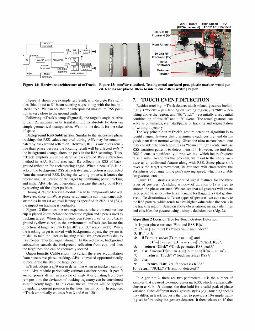
Figure 14: Hardware architecture of mTrack.
60 GHz RF
Front-end (Rx)
Horn Antenna
High Speed
ADC/DAC
Motorized
Rotator
WARP Board
(FPGA back-end)
Motor
Controller
60 Ghz RF
Front-end (Tx)
I/Q
Channels
Figure 15: mmWave testbed. Testing metal-surfaced pen, plastic marker, wood pen-cil. Radios are placed 10cm beside 50cm×50cm writing region.
Figure 11 shows one example test result, with discrete RSS sam-ples (blue dots) at 8◦ beam-steering steps, along with the interpo-lated curve. We can see that the interpolated maximum RSS posi-tion is very close to the ground truth.
Following mTrack’s setup (Figure 5), the target’s angle relativeto each Rx antenna can be translated into its absolute location viasimple geometrical manipulation. We omit the details for the sakeof space.
Background RSS Subtraction. Similar to the successive phasetracking, the RSS values captured during APA may be contami-nated by background reflection. However, RSS is much less sensi-tive than phase because the locating result will be affected only ifthe background change alters the peak in the RSS scanning. Thus,mTrack employs a simple iterative background RSS subtractionmethod in APA. Before use, each Rx collects the RSS of back-ground reflection for each steering angle. When a new APA is in-voked, the background RSS at each steering direction is subtractedfrom the measured RSS. During the writing process, it knows theprecise angular location of the target by combining phase trackingand initial APA. Hence, it periodically rescans the background RSSby steering off the target position.
During APA, the tracking module has to be temporarily blocked.However, since mmWave phase-array antenna can instantaneouslyswitch its beam (at ns level latency as specified in 802.11ad [34]),the impact on tracking is negligible.
Figure 12 illustrates one test experiment, where a metal-surfacecup is placed 25cm behind the detection region and a pen is used astracking target. When there is only pen (blue curve) or only back-ground (yellow curve) in the environment, mTrack can locate thedirection of target accurately (in 40◦ and 30◦ respectively). Whenthe tracking target is mixed with background object, the system ismisled to take the later as locating result (in green curve) due toits stronger reflected signal strength. In the red curve, backgroundsubtraction cancels the background reflection from cup, and thusthe target position can be accurately located.
Opportunistic Calibration. To curtail the error accumulationfrom successive phase tracking, APA is invoked opportunisticallyto recalibrate the absolute target position.
mTrack adopts a k/θ test to determine when to invoke a calibra-tion. APA module periodically estimates anchor points. If past kanchor points all fall in a sector of angle θ originating from cur-rent position, the deviation of tracking trajectory can be consideredas sufficiently large. In this case, the calibration will be appliedby updating current position to the latest anchor point. In practice,mTrack empirically chooses k = 3 and θ = 120◦.
7. TOUCH EVENT DETECTIONBesides tracking, mTrack detects touch-related gestures includ-
ing: (i) “touch” – pen landing on writing region, (ii) “lift” – penlifting above the region, and (iii) “click” – essentially a sequentialcombination of “touch” and “lift” event. The touch gestures canserve as commands, e.g., start/pause of tracking and segmentationof writing trajectory.
The key principle in mTrack’s gesture detection algorithm is toidentify signal features that discriminate each gesture, and distin-guish them from normal writing. Given the ultra-narrow beam, onemay consider the touch gestures as “beam cutting” events, and useRSS variation patterns to detect them [5]. However, we find thatRSS fluctuates significantly during writing, which incurs frequentfalse alarms. To address this problem, we resort to the phase vari-ance as an additional feature along with RSS. Since phase shiftreveals the target’s movement, its variance will characterize theabruptness of change in the pen’s moving speed, which is suitablefor gesture detection.
Figure 13 illustrates a snapshot of signal features for the threetypes of gestures. A sliding window of duration 0.1s is used tosmooth the phase variance. We can see that all gestures will createlarge phase variance, which is amenable for flagging a valid gestureevent. To discriminate different types of gestures, we can resort tothe RSS pattern, which tends to have higher value when the pen is inthe tracking region. Based on above observations, mTrack identifiesand classifies the gesture using a simple decision tree (Alg. 2).
Algorithm 2 Decision Tree for Touch Gesture Detection1: Input: phase variance P[n] and RSS R[n]2: {V,m} ← max(P) /*max value and index*/3: if V > H4: if R[m] > mean(R[m : m+ s]) and
R[m] > mean(R[m− s : m]) /*Check RSS*/5: return “Click” /*Click generates RSS peak*/6: else if mean(R[m : m+ s]) > mean(R[m− s : m])7: return “Touch” /*Touch increases RSS*/8: else9: return “Lift” /*Lift decreases RSS*/
10: return “NULL” /*Event not detected*/
In Algorithm 2, there are two parameters. s is the number ofsamples that are used to compute average RSS, which is empiricallychosen as 0.1s. H denotes the threshold for a valid peak of phasevariance. Since different users’ gesture styles (e.g., touching speed)may differ, mTrack requests the user to provide a 10-sample train-ing set before using the gesture detector. It then selects an H that
40
42
44
46
48
50
52
34 36 38 40 42 44 46Y c
oo
rdin
ate
(cm
)
X coordinate (cm)
BasicSSub
DDBRPCR
Figure 16: Tracking along an example lin-ear trajectory(10 cm) without BG.
40
42
44
46
48
50
52
34 36 38 40 42 44 46Y c
oo
rdin
ate
(cm
)
X coordinate (cm)
BasicSSub
DDBRPCR
Figure 17: Tracking example with back-ground reflection.
0
0.2
0.4
0.6
0.8
1
0 10 20 30 40 50 60 70 80
Fre
qu
en
cy
Tracking error (mm)
BasicSSub
DDBRPCR
Figure 18: Error CDF of tracking methodsunder background reflection.
0
10
20
30
40
50
No Weak StrongTra
ckin
g e
rro
r (m
m)
Background signal strength
BasicPCR
Figure 19: PCR performance under differ-ent background strength.
18
20
22
24
26
28
20 22 24 26 28 30 32 34 36Y c
oord
inate
(cm
)
X coordinate (cm)
-80dBc-83dBc-86dBc
0
10
20
30
40
50
60
-80 -83 -86 -89 -92 -95 -98 -101
Err
or
(mm
)
Phase noise (dBc)
Figure 20: Tracking trajectory and tracking error of the DDBR algorithm under dif-ferent levels of phase noise.
minimizes the difference (computed using standardized Euclideandistance [35]) between the widths of the 10 peaks.
8. IMPLEMENTATION AND EVALUATIONWe use a custom-built 60 GHz software-radio testbed (Figure 14)
to evaluate the viability and performance of mTrack. The testbeduses WARP [36] as baseband processing unit, but extends its car-rier frequency to 60 GHz. Baseband digital waveforms are gen-erated in a host PC, forwarded to WARP, and converted to ana-log using a high-speed DAC. Resulting analog signals are carrier-modulated and transmitted by the Vubiq 60 GHz RF front-end [37].Two receivers are synchronized by a 308.6 MHz external clock sig-nal sourcing from transmitter oscillator. Received signals will bedecoded following reverse path, and eventually reach the PC hostwhich runs mTrack’s algorithms.
Tx and Rx RF front-end each has a waveguide module as inter-face to 60 GHz antennas (Figure 15). Transmitter uses its origi-nal waveguide module PEM-001 as antenna, which is quasi-omni-directional (180◦ beamwidth). Tx sends 5 MHz single-carrier base-band signals modulated by 60 GHz carrier waves. Regarding re-ceiver, we are unaware of any programmable 60 GHz phased-arrayantenna. Thus, in our prototype, signals are captured by a direc-tional receiver with horn antenna PE9881-34 of 3.4◦ beamwidth.To emulate the effect of beam steering, the Rx antenna is mountedon a motion control system [38] that is connected to the PC hostand allows programmable azimuth rotation at 1◦ granularity.
We also implement the RSS/phase extraction module on the 60GHz testbed. It generates and sends single-tone frames (3000 sam-ples each) through Tx, and estimates a pair of RSS and phase valuesfrom each received frame. To avoid phase ambiguity, the changebetween any two phase values cannot exceed π. By default, the ex-traction module samples RSS/phase at 300 Hz. Thus, the highesttracking speed that our prototype can support is 2.5mm×300 Hz/2= 37.5cm/s. The speed is sufficiently fast to capture normal handwriting. Note that 300 Hz phase sampling rate is far below ourhardware limit. With 40 MHz bandwidth, the phase sampling ratecan be up to 40 MHz/3000 = 13 KHz, equivalently translated to atracking speed of 26 m/s.
On top of the RSS/phase extraction, we implement mTrack’s ma-jor modules, i.e., tracking, locating and touch detection. Core pro-cessing algorithms DDBR, PCR and APA are designed as middle-ware plugins that work transparently between RSS/phase extractionand these modules. Algorithms operate on samples that are loadedsequentially into a data buffer.
8.1 Micro Benchmark
8.1.1 Passive Tracking PerformanceThe experiments are conducted in an office environment with
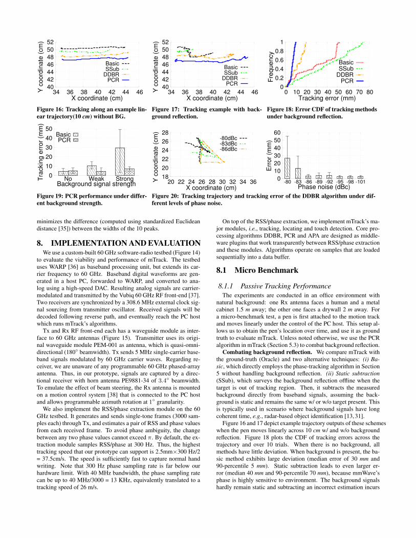
natural background: one Rx antenna faces a human and a metalcabinet 1.5 m away; the other one faces a drywall 2 m away. Fora micro-benchmark test, a pen is first attached to the motion trackand moves linearly under the control of the PC host. This setup al-lows us to obtain the pen’s location over time, and use it as groundtruth to evaluate mTrack. Unless noted otherwise, we use the PCRalgorithm in mTrack (Section 5.3) to combat background reflection.
Combating background reflection. We compare mTrack withthe ground-truth (Oracle) and two alternative techniques: (i) Ba-sic, which directly employs the phase-tracking algorithm in Section5 without handling background reflection. (ii) Static subtraction(SSub), which surveys the background reflection offline when thetarget is out of tracking region. Then, it subtracts the measuredbackground directly from baseband signals, assuming the back-ground is static and remains the same w/ or w/o target present. Thisis typically used in scenario where background signals have longcoherent time, e.g., radar-based object identification [13, 31].
Figure 16 and 17 depict example trajectory outputs of these schemeswhen the pen moves linearly across 10 cm w/ and w/o backgroundreflection. Figure 18 plots the CDF of tracking errors across thetrajectory and over 10 trials. When there is no background, allmethods have little deviation. When background is present, the ba-sic method exhibits large deviation (median error of 30 mm and90-percentile 5 mm). Static subtraction leads to even larger er-ror (median 40 mm and 90-percentile 70 mm), because mmWave’sphase is highly sensitive to environment. The background signalshardly remain static and subtracting an incorrect estimation incurs
0 5
10 15 20 25 30 35
CS MS FS WK1 WK2Tra
ckin
g e
rro
r (m
m)
Human activity
BasicPCR
Figure 21: PCR performance under hu-man as dynamic background.
0
0.2
0.4
0.6
0.8
1
0 0.5 1 1.5 2 2.5 3 3.5 4
Fre
qu
en
cy
Direction Error (deg.)
w/ spline interpw/o spline interp
Figure 22: APA performance with splineinterpolation.
0
1
2
3
4
5
1 2 3 4 5 6 7 8
Err
or
(de
g.)
Beamsteering granularity (deg.)
W/o BGW/ BG
W/BG subtract
Figure 23: Effectiveness of backgroundsubtraction in APA.
0
1
2
3
4
5
6
CS MS FS WK1 WK2
Err
or
(de
g.)
Human activity
W/BGW/BG subtract
Figure 24: APA under dynamic back-ground. Step of antenna steer 4◦.
0 10 20 30 40 50 60 70
0 20 40 60 80 100 120 140Tra
ckin
g e
rro
r (m
m)
Moving distance (cm)
W/o calibrationW/ calibration
Figure 25: Error w/ and w/o opportunisticcalibration.
0
0.2
0.4
0.6
0.8
1
0 50 100 150 200 250
Fre
qu
en
cy
Locating error (mm)
Pen
Marker
Pencil
Figure 26: Locating error of different ma-terials.
large penalty because of equivalently introducing an artificial back-ground.
In contrast, mTrack’s DDBR and PCR algorithms both demon-strate mm-scale precision, with median (90-percentile) error of 11(18) mm and 6.5 (9) mm, respectively. PCR achieves higher accu-racy than DDBR mainly because our 60 GHz software defined ra-dio platform has relatively high phase noise (-80dBc at 5Mhz offsetfrom carrier according to our measurement). It can lead to maxi-mum deviation of up to 0.2 radian within one phase cycle. COTS60 GHz radios have much lower phase noise (typically <110dBcat 5Mhz) [39]. Our trace-based simulation shows that DDBR canoutperform PCR significantly under such noise level.
Impact of phase noise on DDBR performance. We eval-uate DDBR’s performance under different levels of phase noisethrough trace-based simulation. The phase shift of target reflec-tion is generated by simulating the target moving along a triangleof size 5cm×5cm following the setup in Figure 5. Meanwhile, thereis background reflection from a static reflector, whose reflectivity is1/3 of the target. The simulated phase shift is contaminated by thetrace of phase noise collected from our platform.
Figure 20 shows the impact of phase noise. DDBR’s trackingerror decreases by more than 80% when the phase noise is reducedfrom -80dBc to -86dBc, and after background removal, the trajec-tory is close to the oracle shape (triangle). Further reducing thephase noise (to <-86dBc) will not significantly improve trackingperformance since phase noise is sufficiently small for DDBR tofunction correctly.
Different types of background. We now evaluate the perfor-mance of Basic and mTrack (using PCR) under 3 different back-ground types: (i) Strong background: a metal cabinet is placed nearthe tracking region, facing one Rx antenna. (ii) Weak background:a 60 GHz RF absorber is placed at the end of tracking region to iso-late the impact of cabinet on one Rx antenna, leaving backgroundreflection from drywall to the other antenna. (iii) No background:RF absorbers are placed along both the x- and y-axis, protectingboth Rx antennas from background reflection.
We also evaluate mTrack with human as dynamic background:(i) CS, MS, and FS: A human stands 1m, 2m and 3m facing one
Rx antenna. Human breathing changes background reflection sig-nals. (ii) WK1 and WK2: The human randomly walks in parallelor perpendicular at 2∼3m to Rx antenna.
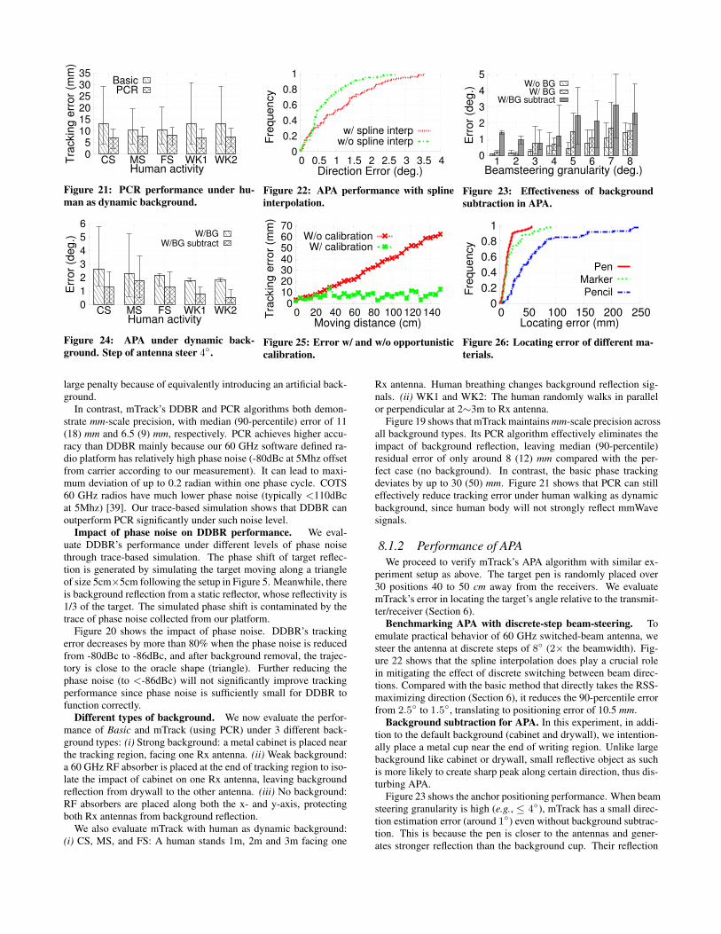
Figure 19 shows that mTrack maintains mm-scale precision acrossall background types. Its PCR algorithm effectively eliminates theimpact of background reflection, leaving median (90-percentile)residual error of only around 8 (12) mm compared with the per-fect case (no background). In contrast, the basic phase trackingdeviates by up to 30 (50) mm. Figure 21 shows that PCR can stilleffectively reduce tracking error under human walking as dynamicbackground, since human body will not strongly reflect mmWavesignals.
8.1.2 Performance of APAWe proceed to verify mTrack’s APA algorithm with similar ex-
periment setup as above. The target pen is randomly placed over30 positions 40 to 50 cm away from the receivers. We evaluatemTrack’s error in locating the target’s angle relative to the transmit-ter/receiver (Section 6).
Benchmarking APA with discrete-step beam-steering. Toemulate practical behavior of 60 GHz switched-beam antenna, westeer the antenna at discrete steps of 8◦ (2× the beamwidth). Fig-ure 22 shows that the spline interpolation does play a crucial rolein mitigating the effect of discrete switching between beam direc-tions. Compared with the basic method that directly takes the RSS-maximizing direction (Section 6), it reduces the 90-percentile errorfrom 2.5◦ to 1.5◦, translating to positioning error of 10.5 mm.
Background subtraction for APA. In this experiment, in addi-tion to the default background (cabinet and drywall), we intention-ally place a metal cup near the end of writing region. Unlike largebackground like cabinet or drywall, small reflective object as suchis more likely to create sharp peak along certain direction, thus dis-turbing APA.
Figure 23 shows the anchor positioning performance. When beamsteering granularity is high (e.g., ≤ 4◦), mTrack has a small direc-tion estimation error (around 1◦) even without background subtrac-tion. This is because the pen is closer to the antennas and gener-ates stronger reflection than the background cup. Their reflection
0
0.2
0.4
0.6
0.8
1
0 10 20 30 40 50 60
Fre
qu
en
cy
Tracking error (mm)
Pen
Marker
Pencil
Figure 27: Tracking error of different ma-terials.
0
20
40
60
80
100
0 20 40 60 80 100
Y C
oo
rdin
ate
(cm
)
X Coordinate (cm)
0
1
2
3
4
5
6
7
Lo
ca
tin
g e
rro
r (c
m)
Figure 28: Error map of APA
0
20
40
60
80
100
0 20 40 60 80 100
Y C
oo
rdin
ate
(cm
)
X Coordinate (cm)
0
1
2
3
4
5
6
7
Tra
ckin
g e
rro
r (c
m)
Figure 29: Error map of Phase-tracking.
0
0.2
0.4
0.6
0.8
1
1 2 3 4 5 6
Accu
racy
User Index
Figure 30: Detection accuracy for differentusers.
15
20
25
30
10 20 30 40 50Y c
oo
rdin
ate
(cm
)
X coordinate (cm)
Figure 31: mTrack example of letter andword.
0 0.2 0.4 0.6 0.8
1 1.2
1 2 3 4 5 6 7
Accu
racy
User Index
Character Word
Figure 32: Character and word recogni-tion accuracy.
peaks can thus be reliably distinguished through fine-grained scan-ning. However, with coarser steering granularity, their peaks tend tomerge, leading to an increasing error. Fortunately, background sub-traction effectively mitigates the impact of background reflection,hence reducing the estimation error by 50%.
Figure 24 shows the APA performance under human movementas dynamic background. Human movement at 2m away from re-ceiver does not affect positioning error, since reflecting RSS fromhuman body is much weaker than pen. Estimation error withoutbackground subtraction increases to 2.8◦ when human stands closeto receive antenna. However, background subtraction can still con-sistently reduce positioning error even under human movement.
8.1.3 Joint Performance of Tracking and APA.Recall APA facilitates phase tracking through opportunistic cali-
bration. In this experiment, we verify the effectiveness of this jointexecution. The target pen moves along a circular trajectory of ra-dius 7 cm. mTrack continuously runs phase tracking, and performsthe k/θ-test (Section 6) every 2 seconds. It invokes APA calibrationif the test dictates so. Figure 25 shows the tracking error at every2-second check point. Without APA calibration, the phase track-ing error steadily accumulates over time and reaches 46 cm whenmoving 150 cm continuously along the circle. In contrast, APA cal-ibration caps the phase tracking error below 10 mm across 90% ofthe trajectory.
8.2 Performance on a TrackpadWe now evaluate mTrack’s performance in a real trackpad ap-
plication. The experiments are conducted in an office environmentwith natural background (drywall, metal cabinet, a user, and occa-sional human walking by). A 50cm×50cm writing region is createdon a wood table. To test the precision of APA in locating anchoringpoints, the user rests the pen tip on 40 random locations, ensuringthe bottom part of the pen is exposed to the antennas. mTrack steersthe antennas with granularity of 8◦. To test phase tracking, the userdraws 10 circles and 10 triangles (with 20 cm perimeter) followingprinted trajectories in the normal hand-writing speed. Since human-hand deformation will affect phase tracking, testers hold the mid-dle portion of pen, while directional antennas point to the bottom
portion. Due to lack of timing-synchronization between user writ-ing trajectory and tracking estimation, we approximate the trackingerror as the minimum projection distance from mTrack’s locationestimation to the trajectory.
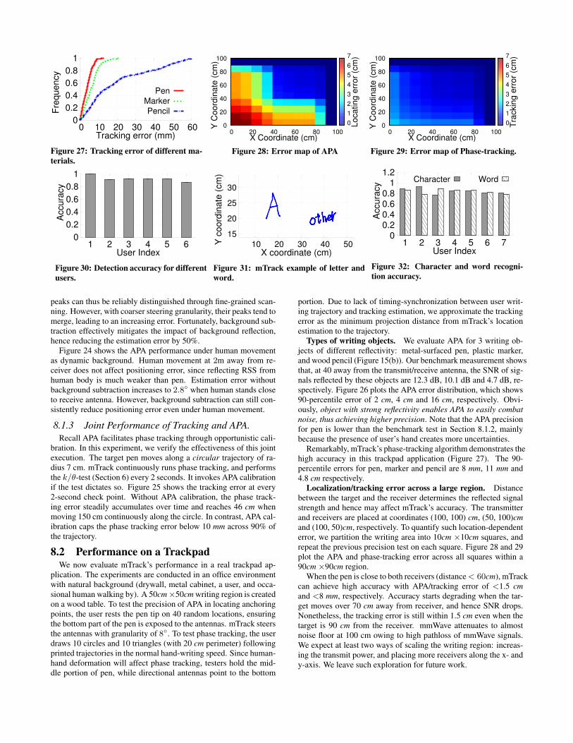
Types of writing objects. We evaluate APA for 3 writing ob-jects of different reflectivity: metal-surfaced pen, plastic marker,and wood pencil (Figure 15(b)). Our benchmark measurement showsthat, at 40 away from the transmit/receive antenna, the SNR of sig-nals reflected by these objects are 12.3 dB, 10.1 dB and 4.7 dB, re-spectively. Figure 26 plots the APA error distribution, which shows90-percentile error of 2 cm, 4 cm and 16 cm, respectively. Obvi-ously, object with strong reflectivity enables APA to easily combatnoise, thus achieving higher precision. Note that the APA precisionfor pen is lower than the benchmark test in Section 8.1.2, mainlybecause the presence of user’s hand creates more uncertainties.
Remarkably, mTrack’s phase-tracking algorithm demonstrates thehigh accuracy in this trackpad application (Figure 27). The 90-percentile errors for pen, marker and pencil are 8 mm, 11 mm and4.8 cm respectively.
Localization/tracking error across a large region. Distancebetween the target and the receiver determines the reflected signalstrength and hence may affect mTrack’s accuracy. The transmitterand receivers are placed at coordinates (100, 100) cm, (50, 100)cmand (100, 50)cm, respectively. To quantify such location-dependenterror, we partition the writing area into 10cm ×10cm squares, andrepeat the previous precision test on each square. Figure 28 and 29plot the APA and phase-tracking error across all squares within a90cm ×90cm region.
When the pen is close to both receivers (distance< 60cm), mTrackcan achieve high accuracy with APA/tracking error of <1.5 cmand <8 mm, respectively. Accuracy starts degrading when the tar-get moves over 70 cm away from receiver, and hence SNR drops.Nonetheless, the tracking error is still within 1.5 cm even when thetarget is 90 cm from the receiver. mmWave attenuates to almostnoise floor at 100 cm owing to high pathloss of mmWave signals.We expect at least two ways of scaling the writing region: increas-ing the transmit power, and placing more receivers along the x- andy-axis. We leave such exploration for future work.
Event Touch Lift Click NDTouch 94.0% 0 0 6.0%Lift 0 93.5% 0 6.5%
Click 0 0 94.8% 5.2%
Table 3: Classification accuracy. ND is not detected.
Accuracy of touch event detection. To verify mTrack’s eventdetection algorithm, we recruit 7 users to perform the “touch”, “lift”and “click” gestures on the writing region using a pen. Each userfirst provides a 10-sample training set to find the best threshold H(Sec. 7), and then repeat each gesture for 50 times to test the de-tection algorithm. Table 3 shows the confusion matrix of gesturedetection among all users, and Figure 30 plots the detection accu-racy of each users over all events. The detection accuracy of allthree types of events is around 94% and does not vary noticeablyacross users. Notably, the event misclassification rate is 0, indicat-ing that the RSS based approach can reliably discriminate differentgesture events owing to the highly directional beams. The miss de-tection of events is mainly due to the variation of users’ touchingspeed, which may not always be consistent with the training set.
8.3 Application of mTrackWe integrate mTrack with a word recognition application to show-
case its potential in computer-human interaction. In specific, werecord the writing trace from mTrack word by word, and then ex-port the trace to control the mouse on a PC that runs the MyScriptStylus [40] word recognition software. mTrack’s event detectoris used to segment the connections between characters in a word.Figure 31 shows two examples when we use mTrack to track thecharacter/word trajectory, which exhibit high fidelity even if eachcharacter spans only 1 or 2 cm.
We further recruit 7 users to each write 100 random charactersand 50 words using metal-surfaced pen on a 15 cm× 15cm writingregion. The words are randomly picked from the standard MacKen-zie set [41], which well represents the usage frequency of Englishwords. Figure 32 plots the recognition accuracy across users. Theaccuracy for both character and word ranges from 81 to 89% acrossusers. Users also perform the same test on a real trackpad, and therecognition accuracy is from 88 to 92%, which shows that mTrack’sperformance is close to the trackpad. Considering the potentialpenetration of portable millimeter-wave radios [8, 9], we believemTrack holds potential as a new form of “in-situ” transcription sys-tem.
9. DISCUSSIONObject shape and size. mTrack is designed to track writing ob-
jects of small size, like pen or marker, which can be approximatedas a point reflector, because their dimension (with diameter≈ 1cm)is much smaller than its distance to the antennas (> 20cm). Objectswith deformable shape or large size, e.g. human hand and body,do not possess these properties, and hence cannot use mTrack’smodel-driven tracking algorithm. Similarly, mTrack can not differ-entiate phase change due to large hand-shape deformation. Thus,users need to keep a relatively consistent hand shape when writingto avoid confusing the tracking algorithm. They also need to en-sure a sizable part of the pen is exposed to the Tx/Rx to reflect themmWave signals.
Phased-Array Antennas. Due to hardware limitation, we areonly able to evaluate our concept with directional antennas. Beampattern of a horn antenna differs slightly from that of an 802.11adphase-array in two aspects: (i) The beamwidth of a phased-array
is dependent on steering direction. For example, for a linear an-tenna array, beamwidth along 0◦ direction can be twice of that along90◦ [30]. However, since beamforming codebook is predefined andknown, we can still compensate the gain distortion of discrete sam-pling. The systematic solution to this problem will be left for ourfuture work. (ii) Sidelobes of a phased array may be relatively largecompared with that of a directional horn antenna. Sidelobes maycapture signals from undesired directions. However, since they usu-ally have much smaller gain compared to the main lobe, as long asthere is a RSS peak when pointing to the target, mTrack’s beam-steering based APA mechanism can still work.
Tracking multiple objects. mTrack can be potentially extendedto track multiple targets simultaneously. When the objects are suf-ficiently separated, and not falling in the same beam direction, thereceiver radios can steer the beam towards different objects in atime-interleaving manner and update their tracking trajectories se-quentially. Further exploration of this idea is left for our futurework.
10. CONCLUSIONWe have presented mTrack, a high precision passive object track-
ing system that uses 60 GHz signals as sensing medium. mTracktakes advantage of the short wavelength and steerable directionalbeams of 802.11ad-like 60 GHz radio devices, and uses subtle RSS/phase variation to track passive writing objects on a trackpad-likearea. It can track a pen at sub-centimeter level accuracy, which evenoutperforms existing systems that use radio-instrumented objects.Considering the growing popularity of 60 GHz devices, we believemTrack can potentially open up a wide range of mobile sensingapplications.
AcknowledgementWe appreciate the constructive comments from anonymous review-ers. The work reported in this paper was supported in part bythe NSF under Grant CNS-1318292, CNS-1343363, CNS-1350039and CNS-1404613.
11. REFERENCES[1] J. P. Wachs, M. Kölsch, H. Stern, and Y. Edan, “Vision-based
Hand-gesture Applications,” Communications of the ACM, vol. 54,no. 2, 2011.
[2] K. McElhearn, “Leap motion controller fails in normal conditions,”http://www.mcelhearn.com/not-a-review-leap-motioncontroller-fails-in-normal-conditions/,2014.
[3] “RoboRealm: Microsoft Kinect.”http://www.roborealm.com/help/Microsoft Kinect.php, 2013.
[4] Q. Pu, S. Gupta, S. Gollakota, and S. Patel, “Whole-home GestureRecognition using Wireless Signals,” in ACM MobiCom, 2013.
[5] P. Melgarejo, X. Zhang, P. Ramanathan, and D. Chu, “LeveragingDirectional Antenna Capabilities for Fine-grained GestureRecognition,” in ACM UbiComp, 2014.
[6] L. Yang, Y. Chen, X.-Y. Li, C. Xiao, M. Li, and Y. Liu, “Tagoram:Real-time Tracking of Mobile RFID Tags to High Precision usingCOTS Devices,” in ACM MobiCom, 2014.
[7] “IEEE 802.11ad PHY Specifications: Enhancements for Very HighThroughput in the 60 GHz Band,” 2012.
[8] Dailywireless, “60 GHz Backhaul for Small Cells,” 2013. [Online].Available: http://www.dailywireless.org/2014/01/03/60ghz-backhaul-for-small-cells/
[9] PC Magazine, “Wilocity Unveils Blazing Fast 802.11ad SmartphoneWi-Fi Chip,” 2014. [Online]. Available:http://www.pcmag.com/article2/0,2817,2454187,00.asp
[10] J. Wang, D. Vasisht, and D. Katabi, “RF-IDraw: Virtual Touch Screenin the Air using RF Signals,” in ACM SIGCOMM, 2014.
[11] N. Patwari, L. Brewer, Q. Tate, O. Kaltiokallio, and M. Bocca,“Breathfinding: A Wireless Network That Monitors and LocatesBreathing in a Home,” JSAC, vol. 8, no. 1, 2014.
[12] C. Xu, B. Firner, R. S. Moore, Y. Zhang, W. Trappe, R. Howard,F. Zhang, and N. An, “SCPL: Indoor Device-free Multi-subjectCounting and Localization Using Radio Signal Strength,” in Proc. ofACM/IEEE IPSN, 2013.
[13] F. Adib and D. Katabi, “See Through Walls with WiFi!” in Proc. ofACM SIGCOMM, 2013.
[14] F. Adib, Z. Kabelac, D. Katabi, and R. C. Miller, “3D Tracking viaBody Radio Reflections,” in Proc. of USENIX NSDI, 2014.
[15] A. Edelstein and M. Rabbat, “Background Subtraction for OnlineCalibration of Baseline RSS in RF Sensing Networks,” CoRR, vol.abs/1207.1137, 2012.
[16] A. Maltsev and R. Maslennikov and A. Sevastyanov and A. Lomayevand A. Khoryaev, “Statistical Channel Model for 60 GHz WLANSystems in Conference Room Environment,” in Proc. of EuropeanConference on Antennas and Propagation, 2010.
[17] “VICON.” http://www.vicon.com/.[18] H. Wang, S. Sen, A. Elgohary, M. Farid, M. Youssef, and R. R.
Choudhury, “No Need to War-drive: Unsupervised IndoorLocalization,” ser. ACM MobiSys, 2012.
[19] S. Sen, B. Radunovic, and et al, “Spot Localization using PHY LayerInformation,” in ACM MobiSys, 2012.
[20] H. Liu, Y. Gan, J. Yang, S. Sidhom, Y. Wang, Y. Chen, and F. Ye,“Push the Limit of WiFi Based Localization for Smartphones,” inACM MobiCom, 2012.
[21] H. Fang, “60 GHz RSS Localization with Omni-directional and HornAntennas,” Ph.D. dissertation, 2010.
[22] J. Nanzer, Microwave and millimeter-wave remote sensing forsecurity applications. Artech House, 2012.
[23] G. Ossberger, T. Buchegger, E. Schimback, A. Stelzer, and R. Weigel,“Non-invasive respiratory movement detection and monitoring ofhidden humans using ultra wideband pulse radar,” in Conference onUltrawideband Systems and Technologies, 2004.
[24] M. Youssef, M. Mah, and A. Agrawala, “Challenges: Device-freePassive Localization for Wireless Environments,” in Proc. of ACMMobiCom, 2007.
[25] B. Wei, A. Varshney, W. Hu, N. Patwari, and C. T. Chou, “dRTI:Directional RadioTomographic Imaging,” CoRR, vol. abs/1402.2744,2014.
[26] Huang, Donny and Nandakumar, Rajalakshmi and Gollakota,Shyamnath, “Feasibility and Limits of Wi-Fi Imaging,” in ACMSenSys, 2014.
[27] Y. Zhu, Y. Zhu, Z. Zhang, B. Y. Zhao, and H. Zheng, “60ghz mobileimaging radar,” ser. HotMobile ’15, 2015.
[28] “TDK IS-005A RF Absorber,” http://www.tdk.com/.
[29] K. Abbas, “A new recurrent approach for phase unwrapping,”International Journal of Applied Science and Engineering, 2005.
[30] J. Wang, Z. Lan, C.-S. Sum, and et al, “Beamforming CodebookDesign and Performance Evaluation for 60GHz Wideband WPANs,”in IEEE Vehicular Technology Conference, 2009.
[31] J. Nanzer, Microwave and Millimeter-Wave Remote Sensing forSecurity Applications. Artech House, 2012.
[32] P. V. Nikitin, R. Martinez, S. Ramamurthy, H. Leland, G. Spiess, andK. Rao, “Phase based spatial identification of UHF RFID tags,” inIEEE International Conference on RFID, 2010.
[33] J. LindstrÃum, H. Kokko, and E. Ranta, “Detecting Periodicity inShort and Noisy Time Series Data,” Oikos, vol. 78, no. 2, 1997.
[34] A. Valdes-Garcia, S. Reynolds, A. Natarajan, D. Kam, D. Liu, J.-W.Lai, Y.-L. Huang, P.-Y. Chen, M.-D. Tsai, J.-H. Zhan et al.,“Single-element and phased-array transceiver chipsets for 60-GHzGb/s communications,” Communications Magazine, IEEE, 2011.
[35] I. H. Witten and E. Frank, Data Mining: Practical Machine LearningTools and Techniques. Morgan Kaufmann Publishers, 2005.
[36] Rice University, “Wireless Open-Access Research Platform,”http://warp.rice.edu/trac/wiki, 2013.
[37] “Vubiq 60GHz System,” http://vubiq.com/v60wgd03/, 2014.[38] “Axis360 Motion Control System,” http://cinetics.com/two-axis360/.[39] A. Waheed and A. Ashik, “Mitigation of Phase Noise at
Millimeter-Wave Frequencies for Wireless Personal Area NetworkApplications,” Masters Theses, 2008.
[40] “MyScript technology,” http://myscript.com/technology/, 2015.[41] I. S. MacKenzie and R. W. Soukoreff, “Phrase Sets for Evaluating
Text Entry Techniques,” in ACM CHI Extended Abstracts, 2003.
APPENDIXA. PROOF OF EQUATION (4)
In this section, we derive the rationale behind background re-moval as stated in Equation (4). For clarity, we introduce the fol-lowing notations: θ1 = ∆ arg(
−→S trg)
tt−1, θ2 = ∆ arg(
−→S trg)
t+1t ,
and θ3 = arg(−→S t+1
trg −−→S t
trg) − arg(−→S t
trg −−→S t−1
trg ). Since thetarget’s reflection signal strength remains similar among three con-secutive samples, the two triangles in solid line of Figure 9 can beconsidered as isosceles triangles. Following the geometrical rela-tion, we have:
π − θ1
2+π − θ2
2+ θ3 = π,
or equivalently θ3 = θ1+θ22
, which proves Equation (4). ut