heliotrack programmable dual axis solar tracking …heliotrack.com/manuals/v3.3 manual.pdf ·...
TRANSCRIPT
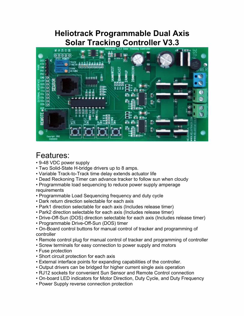
Heliotrack Programmable Dual AxisSolar Tracking Controller V3.3
Features:• 9-48 VDC power supply• Two Solid-State H-bridge drivers up to 8 amps.• Variable Track-to-Track time delay extends actuator life• Dead Reckoning Timer can advance tracker to follow sun when cloudy• Programmable load sequencing to reduce power supply amperagerequirements• Programmable Load Sequencing frequency and duty cycle• Dark return direction selectable for each axis• Park1 direction selectable for each axis (Includes release timer)• Park2 direction selectable for each axis (Includes release timer)• Drive-Off-Sun (DOS) direction selectable for each axis (Includes release timer)• Programmable Drive-Off-Sun (DOS) timer• On-Board control buttons for manual control of tracker and programming ofcontroller• Remote control plug for manual control of tracker and programming of controller• Screw terminals for easy connection to power supply and motors• Fuse protection• Short circuit protection for each axis• External interface points for expanding capabilities of the controller.• Output drivers can be bridged for higher current single axis operation• RJ12 sockets for convenient Sun Sensor and Remote Control connection• On-board LED indicators for Motor Direction, Duty Cycle, and Duty Frequency• Power Supply reverse connection protection

Primary Applications:Single-Axis, Twin Single-Axis, and Dual-Axis solar tracking.
Controller can also be adapted for…Pump controlThermostat controlServo controlMotor controls based on voltage comparisons
Specifications:Specification Value
Power supply 9 – 48 Volts DC
Idle current drain 14 milliamps
Sun Sensor and Logic powersupply
5.0 Volts DC (50 milliamps)
Motor Output voltage Equal to power supply minus
Continuous output Power 100 Watts per axis
Continuous output current 12VDC = 8 Amps (100% dutycycle)
Continuous output current 24VDC = 6 Amps (100% dutycycle)
Continuous output current 36VDC = 4 Amps (100% dutycycle)
Continuous output current 48VDC = 3 Amps (100% dutycycle)
Controller circuit description:Although this controller was designed primarily for dual axis solartracking it can also be used for control of other loads requiring DCcurrent up to 8 amps. Possible applications include, but are notlimited to, circulation pumps, relays, solenoids, fans, motion control,and system monitoring. The controller is capable of driving up to twoloads at once.
The dual axis solar tracking controller features three inputs and twosolid state H-bridge driver outputs. Inputs 1A & 2A are voltagecomparators that control bi-directional DC outputs, input ML is awindow comparator whose input is compared to the TrackingThreshold and Dark Return Threshold.
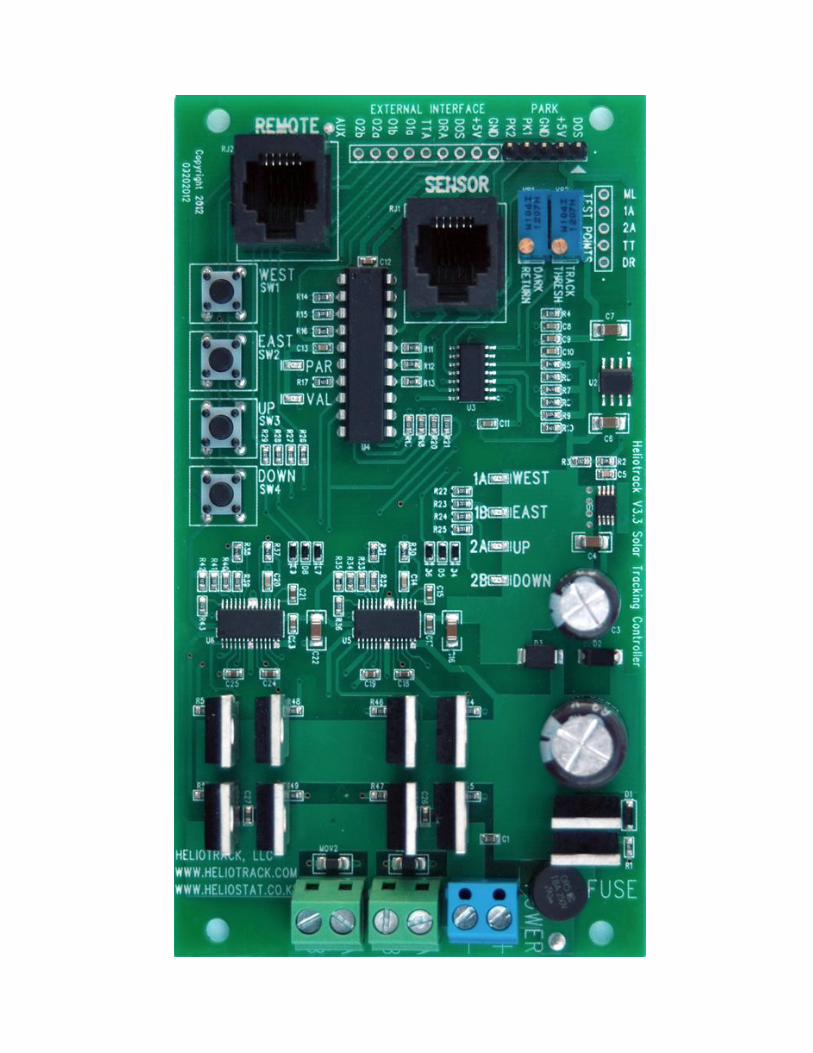
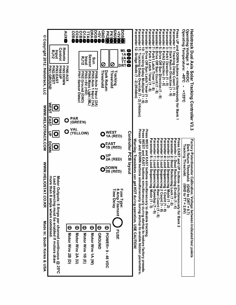
• Power: +12-48 VDC positive terminal of power supply• Ground: Negative terminal of power supply• Motor wire 1A (W) WEST: Usually wired to the East-West actuator -Positive when moving West (Reversed in Southern Hemisphere)• Motor wire 1B (E) EAST: Usually wired to the East-West actuator -Positive when moving East (Reversed in Southern Hemisphere)• Motor wire 2A (U) UP: Usually wired to the Up-Down actuator -Positive when moving Up• Motor wire 2B (D) DOWN: Usually wired to the Up-Down actuator -Positive when moving Down• Fuse: 8 amp slow-blow fuse for actuator motors• Tracking Threshold: Turn clockwise to decrease Sun Sensorsensitivity and increase the amount of sunlight required to activatetracking. Turn counterclockwise to increase Sun Sensor sensitivityand activate tracking with less sunlight.• Dark Return Threshold: Turn clockwise if ambient light is keepingthe tracker from returning at night. Turn counterclockwise if thetracker is returning in heavy cloud conditions before nightfall.
• Sun Sensor: There are up to two "Sun Sensor” sockets that areinterchangeable. This is where you plug in the Sun Sensor.-- Pin 1 : Sun Sensor Detect-- Pin 2 : Ground-- Pin 3: 5.0 VDC-- Pin 4: Dark Return Input-- Pin 5: East-West Tracking Input-- Pin 6: Up-Down Tracking Input• Remote: There is one Remote plug for connecting an externalRemote Control. Connecting remote control pins will move the trackeras follows assuming the tracker is located in the NorthernHemisphere facing South-- 1 & 2 WEST (W) Positive / (E) Negative (Opposite for southernhemisphere)-- 1 & 3 EAST (W) Negative / (E) Positive (Opposite for southernhemisphere)-- 1 & 4 UP (U) Positive / (D) Negative-- 1 & 5 DOWN (U) Negative / (D) Positive
*** Never apply power to the motor terminals. This will destroy thedriver transistors and incur a $75 fix it fee. YOU MUST disconnect themotor wires from the tracking controller if you want to test yourmotors by connecting them directly to the power supply.If you do happen to damage the boards from mishandling thenremove the controller board from the plastic enclosure and send itback to us in a padded mailer. We will fix the board within one weekand ship it back to you USPS Priority.
LED indicators:WEST (RED) Motor Wire 1A (W) is positive.EAST (RED) Motor Wire 1B (E) is positive.UP (RED) Motor Wire 2A (U) is positiveDOWN (RED) Motor Wire 2B (D) is positive
PAR (GREEN) Parameter indicator (Also power, data read, activemotor and Park mode indicator)VAL (YELLOW) Parameter Value indicator (Also data write, activemotor, and Park mode indicator)
Installation instructions:1) Mount the tracking controller box in an accessible location. Be sureto mount the box with the wire holes leading down, this will preventwater from running into the box.
2) Connect the motor wires from your actuators to the motor terminalson the circuit board.•Motor terminals W and E should control the WEST-EAST orAZIMUTH actuator.•Motor terminals U and D should control the UP-DOWN or ALTITUDEactuator.•In the Northern Hemisphere Motor wire W will be positive when thetracker needs to move WEST.•Motor wire E will be positive when the tracker needs to tilt UP.Reverse the polarity of the motor wires if an actuator is moving in thewrong.•In the southern hemisphere the polarity of the EAST-WEST motorwires should be reversed.
3) The sun sensor should be mounted to the tracking plane (solarpanels or concentrator) with the cable leading in the Tilt-Downdirection, or South when the tracker is at the Noon position in theNorthern Hemisphere. The sensor comes with floating spring mountsfor convenient calibration. Remove the wing nuts and one washerfrom each mounting bolt (this leaves one washer and the spring oneach bolt). Pass the three bolts through pre-drilled holes on yoursensor bracket, then replace the washer and then the wing nut oneach bolt. This provides a spring-loaded tripod mount for yoursensor. Fine-tune the alignment of the sensor by turning the wingnuts in the appropriate direction.
4) WITHOUT THE POWER ON... connect your 9 - 48 VDC powersupply wires to the power terminals on the tracking circuit. Be sure toverify polarity, especially when bypassing the reverse protectiondiode for high-amperage operation. Verify connections and turn onthe power. The GREEN LED should flash quickly 15 times while thecontroller loads the user saved parameters from memory.
5) If an actuator is tracking in the wrong direction, disconnect thepower, reverse the polarity of the motor wires for that actuator, andreconnect the power.
6) Replace the cover on the control box when you are satisfied thateverything is working properly. Make sure that the stress grommet onthe sun sensor cable is seated in the notch on the controller box. Donot over tighten the screws when replacing the enclosure lid, it maycause the lid to warp enough to break the rubber seal around theedge and water to penetrate into the box.
Load Sequencing (Duty Cycle):Load sequencing alternates power to the motors, this reduces themaximum current draw of the controller to the current draw of thehighest amperage motor.
Load sequencing can also reduce the on-time of each actuator toprevent overheating of the driver transistors when using actuatorsdrawing greater than 4 amps. Using Load Sequencing in this wayalso requires replacing the stock filament fuses with polyfuses thatcan permit greater amperage spikes without tripping.
Tracking Delay:The Tracking Delay setting controls the time the controller waitsbetween tracking corrections. Concentrator applications usuallyrequire higher accuracy and need to make tracking corrections morefrequently so a Time Delay of less than 30 seconds is recommended.PV tracking applications do not require such precise accuracy so werecommend a Time Delay of more than 30 seconds. Time delay canalso be used to mitigate "back tracking" or “back-lashing” caused bythe tracker traveling past the sun and then tracking in the oppositedirection during the next tracking correction. Greater Tracking Delaysmean the motors turn on and off fewer times per day generallyincreasing actuator life.
Relay Controller Option:If your actuators draw more than 8 amps then relays can be used tosupply power to the actuators. See the “Schematic” link on ourwebsite for details.
Limit Switches:Limit Switches are required for each direction for every actuator whenusing Heliotrack solar tracking products! Many actuators on themarket include internal limit switches but the user must verify thisbefore connecting actuator motors to the tracking controller. It is alsonecessary to verify that the limit switches are set to stop the motorsbefore any damage is done to tracking mechanism due to over-traveling. If your actuators do not include limit switches then pleasesee the “Schematics” link on our website for details.
The External Interface points O1A, O1B, O2A, O2B can be used forlogic level limit switching. Limit switches using these test points donot have to carry high amperage as they work at logic level and onlyneed to carry 10 milliamps. See the External Interface portion of thismanual for details.
Disclaimer:Heliotrack,LLC assumes no liability or responsibility for damagescaused by the use or misuse of our products. Although this controlleris low voltage it is capable of supplying very high amperages. Somecomponents, particularly the driver transistors and reverse connectionprotection diode, can reach temperatures of up to 150 degreescentigrade during operation and much higher if they fail for somereason. We strongly recommend that anyone working withelectronics with exposed components wear eye protection, it is notuncommon for a failing electronic component to explode expelling bitsof hot shrapnel.Don’t mean to scare you… just please use caution.
Never have combustibles near electronic circuitry or motors.
STARTUP BUTTON FUNCTIONSAvailable while the controller is starting up by pressingindicated buttons while connecting power to the controller.
Pressing WEST & EAST buttons simultaneously whilepowering up the controller restores the factory presets.
Pressing UP & DOWN buttons simultaneously whilepowering up the controller allows access to hiddenParameters 11 (Time Delay Override) and 12 (Bridge Mode)in the programming mode Bank 1.
OPERATION BUTTON FUNCTIONSAvailable after startup is complete.
Remote ControlPressing WEST button will turn on motor wire1A (W)
Pressing EAST button will turn on motor wire1B (E)
Pressing UP button will turn on motor wire (Up)
Pressing DOWN button will turn on motor wire (Down)
Pressing WEST & EAST buttons simultaneously will togglebetween Tracking Enable and Tracking Disable. Entering orexiting this mode is indicated by three short blinks. Whentracking is disabled the green and yellow lights will continueto blink three short blinks.
Pressing UP & DOWN button simultaneously enters theprogramming mode Bank 1.
Pressing Up & Down button simultaneously enters theprogramming mode Bank 2.
PROGRAMMING MODE (V3.3 controller with V3.1 Firmware)
1) Entering programming mode:Pressing UP and DOWN buttons simultaneously for asecond will enter the programming mode For Bank 1.Pressing EAST and UP buttons simultaneously for a secondwill enter the programming mode For Bank 2.
PAR (Green) indicates which PARAMETER is selected.VAL (Yellow) indicates the VALUE of the current parameter.
WEST button:Advance to the next parameter.If the Parameter is the one in that bank then it will wrap backaround to Parameter1
EAST button:Display current parameter and increase the value of thecurrent parameter by one.When the value is at maximum it will wrap back around to avalue of 1
UP button:Display the current parameter without changing value.
DOWN button:Exit programming mode and write any changes to memory.The controller only accepts input from the buttons after theparameter and value have been completely displayed.
Programmable Parameters Bank 1PARAMETER
NAME
GREENLED
BLINKS
Parameter Selected PARAMETERVALUE
YELLOW LEDBLINKS
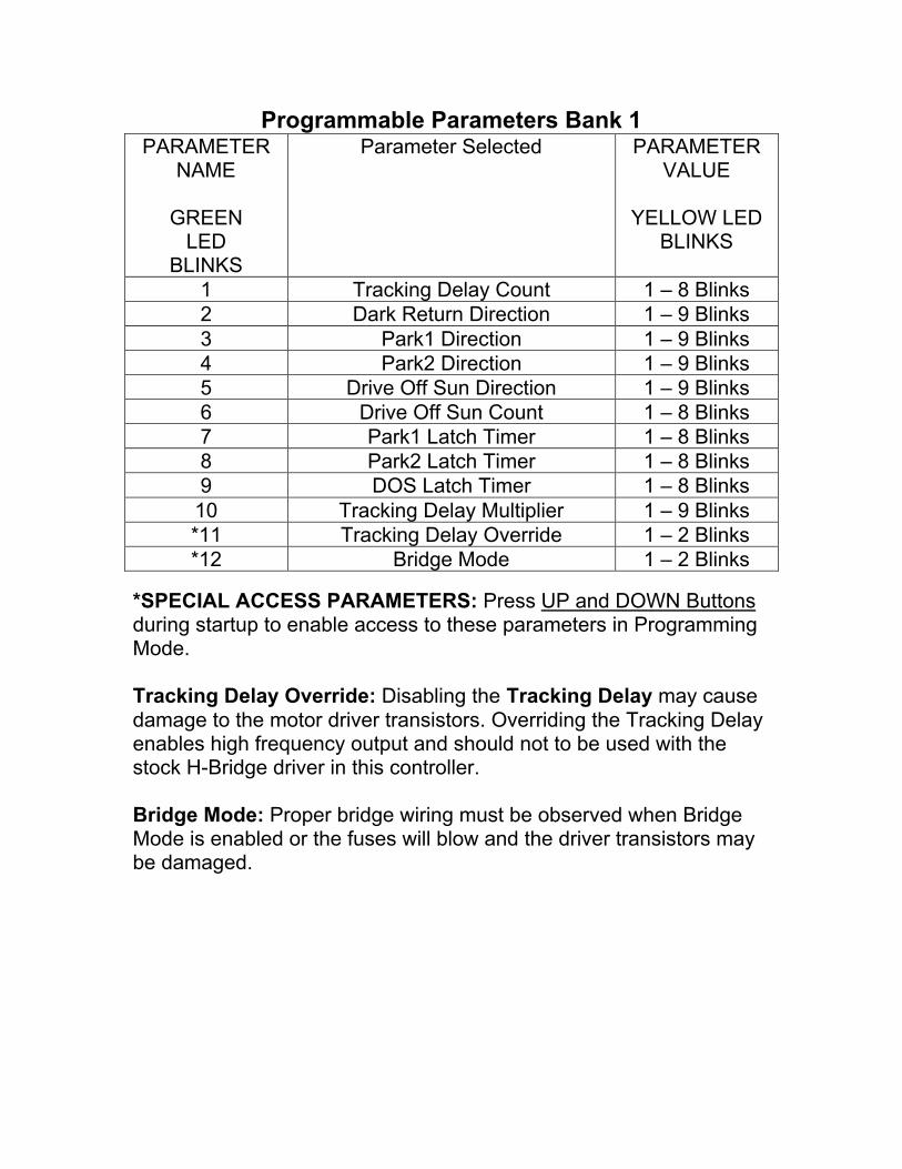
1 Tracking Delay Count 1 – 8 Blinks2 Dark Return Direction 1 – 9 Blinks3 Park1 Direction 1 – 9 Blinks4 Park2 Direction 1 – 9 Blinks5 Drive Off Sun Direction 1 – 9 Blinks6 Drive Off Sun Count 1 – 8 Blinks7 Park1 Latch Timer 1 – 8 Blinks8 Park2 Latch Timer 1 – 8 Blinks9 DOS Latch Timer 1 – 8 Blinks10 Tracking Delay Multiplier 1 – 9 Blinks*11 Tracking Delay Override 1 – 2 Blinks*12 Bridge Mode 1 – 2 Blinks
*SPECIAL ACCESS PARAMETERS: Press UP and DOWN Buttonsduring startup to enable access to these parameters in ProgrammingMode.
Tracking Delay Override: Disabling the Tracking Delay may causedamage to the motor driver transistors. Overriding the Tracking Delayenables high frequency output and should not to be used with thestock H-Bridge driver in this controller.
Bridge Mode: Proper bridge wiring must be observed when BridgeMode is enabled or the fuses will blow and the driver transistors maybe damaged.
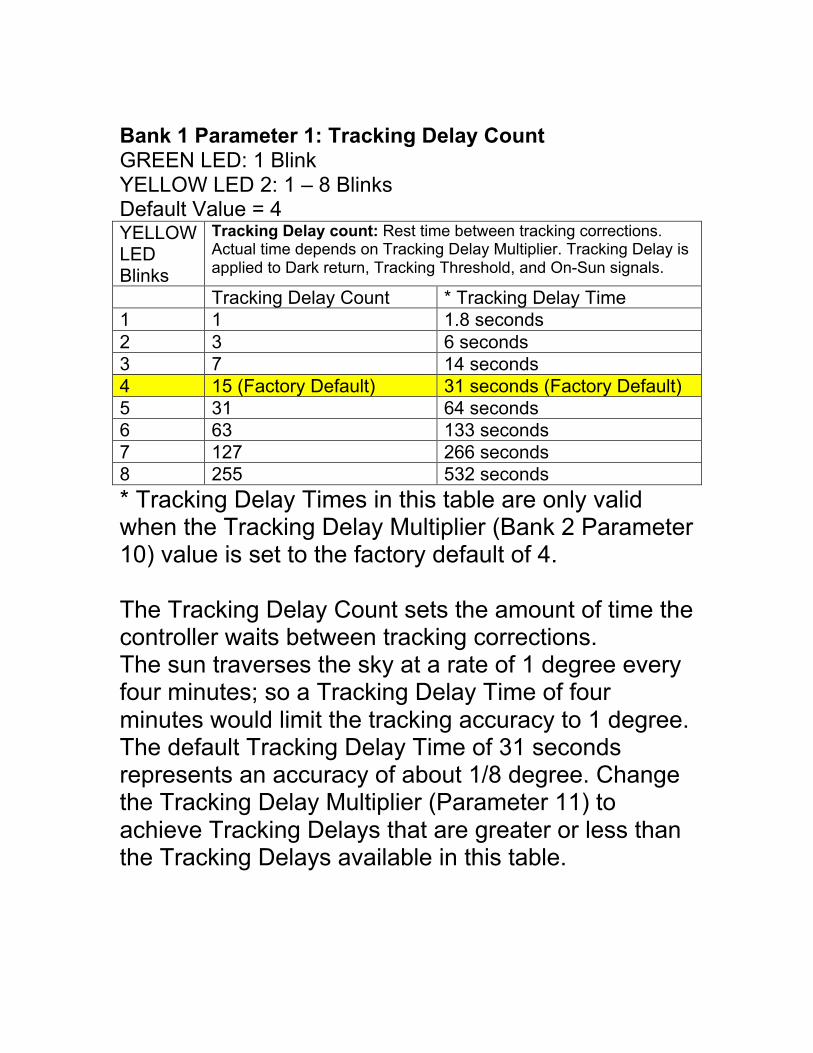
Bank 1 Parameter 1: Tracking Delay CountGREEN LED: 1 BlinkYELLOW LED 2: 1 – 8 BlinksDefault Value = 4YELLOWLEDBlinks
Tracking Delay count: Rest time between tracking corrections.Actual time depends on Tracking Delay Multiplier. Tracking Delay isapplied to Dark return, Tracking Threshold, and On-Sun signals.
Tracking Delay Count * Tracking Delay Time1 1 1.8 seconds2 3 6 seconds3 7 14 seconds4 15 (Factory Default) 31 seconds (Factory Default)5 31 64 seconds6 63 133 seconds7 127 266 seconds8 255 532 seconds
* Tracking Delay Times in this table are only validwhen the Tracking Delay Multiplier (Bank 2 Parameter10) value is set to the factory default of 4.
The Tracking Delay Count sets the amount of time thecontroller waits between tracking corrections.The sun traverses the sky at a rate of 1 degree everyfour minutes; so a Tracking Delay Time of fourminutes would limit the tracking accuracy to 1 degree.The default Tracking Delay Time of 31 secondsrepresents an accuracy of about 1/8 degree. Changethe Tracking Delay Multiplier (Parameter 11) toachieve Tracking Delays that are greater or less thanthe Tracking Delays available in this table.
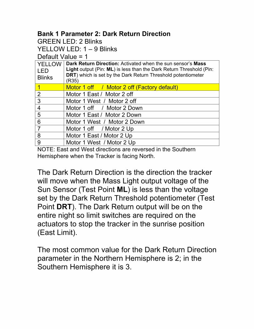
Bank 1 Parameter 2: Dark Return DirectionGREEN LED: 2 BlinksYELLOW LED: 1 – 9 BlinksDefault Value = 1YELLOWLEDBlinks
Dark Return Direction: Activated when the sun sensor’s MassLight output (Pin: ML) is less than the Dark Return Threshold (Pin:DRT) which is set by the Dark Return Threshold potentiometer(R35)
1 Motor 1 off / Motor 2 off (Factory default)2 Motor 1 East / Motor 2 off3 Motor 1 West / Motor 2 off4 Motor 1 off / Motor 2 Down5 Motor 1 East / Motor 2 Down6 Motor 1 West / Motor 2 Down7 Motor 1 off / Motor 2 Up8 Motor 1 East / Motor 2 Up9 Motor 1 West / Motor 2 UpNOTE: East and West directions are reversed in the SouthernHemisphere when the Tracker is facing North.
The Dark Return Direction is the direction the trackerwill move when the Mass Light output voltage of theSun Sensor (Test Point ML) is less than the voltageset by the Dark Return Threshold potentiometer (TestPoint DRT). The Dark Return output will be on theentire night so limit switches are required on theactuators to stop the tracker in the sunrise position(East Limit).
The most common value for the Dark Return Directionparameter in the Northern Hemisphere is 2; in theSouthern Hemisphere it is 3.
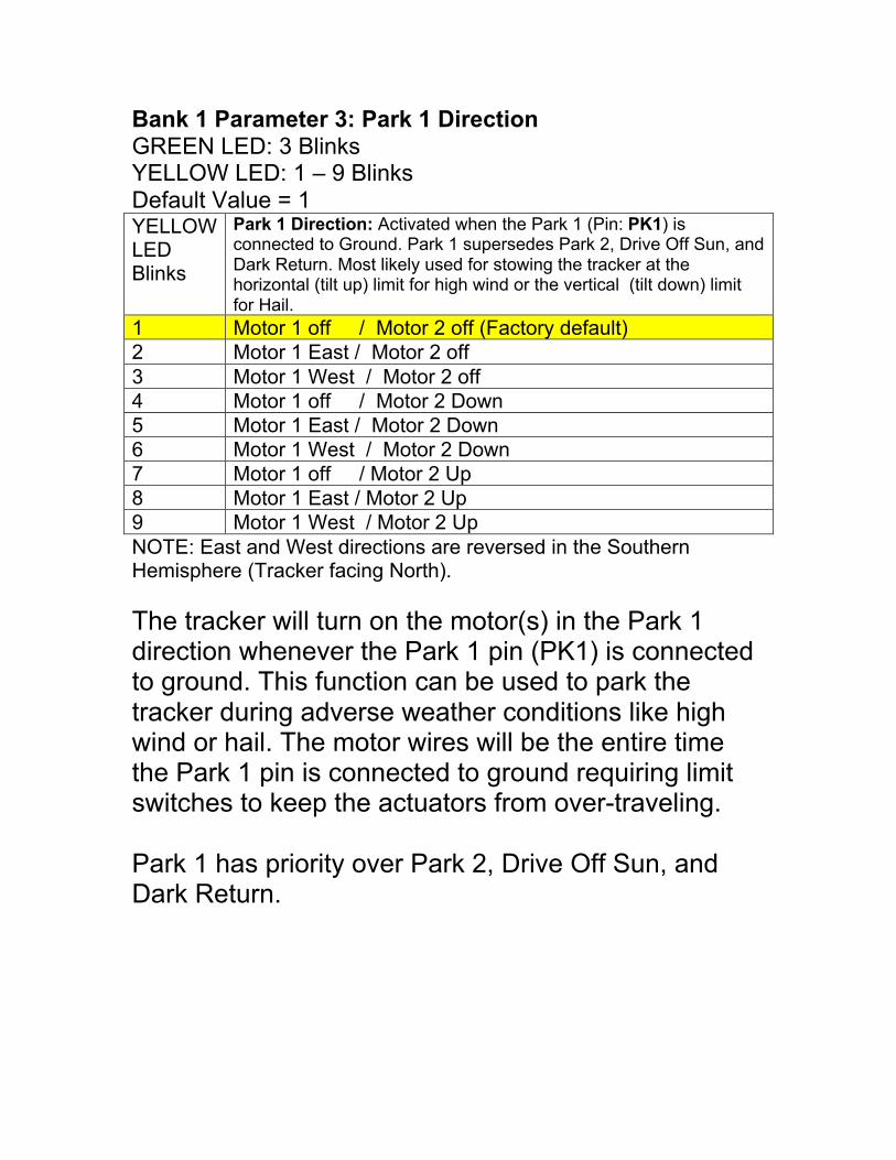
Bank 1 Parameter 3: Park 1 DirectionGREEN LED: 3 BlinksYELLOW LED: 1 – 9 BlinksDefault Value = 1YELLOWLEDBlinks
Park 1 Direction: Activated when the Park 1 (Pin: PK1) isconnected to Ground. Park 1 supersedes Park 2, Drive Off Sun, andDark Return. Most likely used for stowing the tracker at thehorizontal (tilt up) limit for high wind or the vertical (tilt down) limitfor Hail.
1 Motor 1 off / Motor 2 off (Factory default)2 Motor 1 East / Motor 2 off3 Motor 1 West / Motor 2 off4 Motor 1 off / Motor 2 Down5 Motor 1 East / Motor 2 Down6 Motor 1 West / Motor 2 Down7 Motor 1 off / Motor 2 Up8 Motor 1 East / Motor 2 Up9 Motor 1 West / Motor 2 UpNOTE: East and West directions are reversed in the SouthernHemisphere (Tracker facing North).
The tracker will turn on the motor(s) in the Park 1direction whenever the Park 1 pin (PK1) is connectedto ground. This function can be used to park thetracker during adverse weather conditions like highwind or hail. The motor wires will be the entire timethe Park 1 pin is connected to ground requiring limitswitches to keep the actuators from over-traveling.
Park 1 has priority over Park 2, Drive Off Sun, andDark Return.
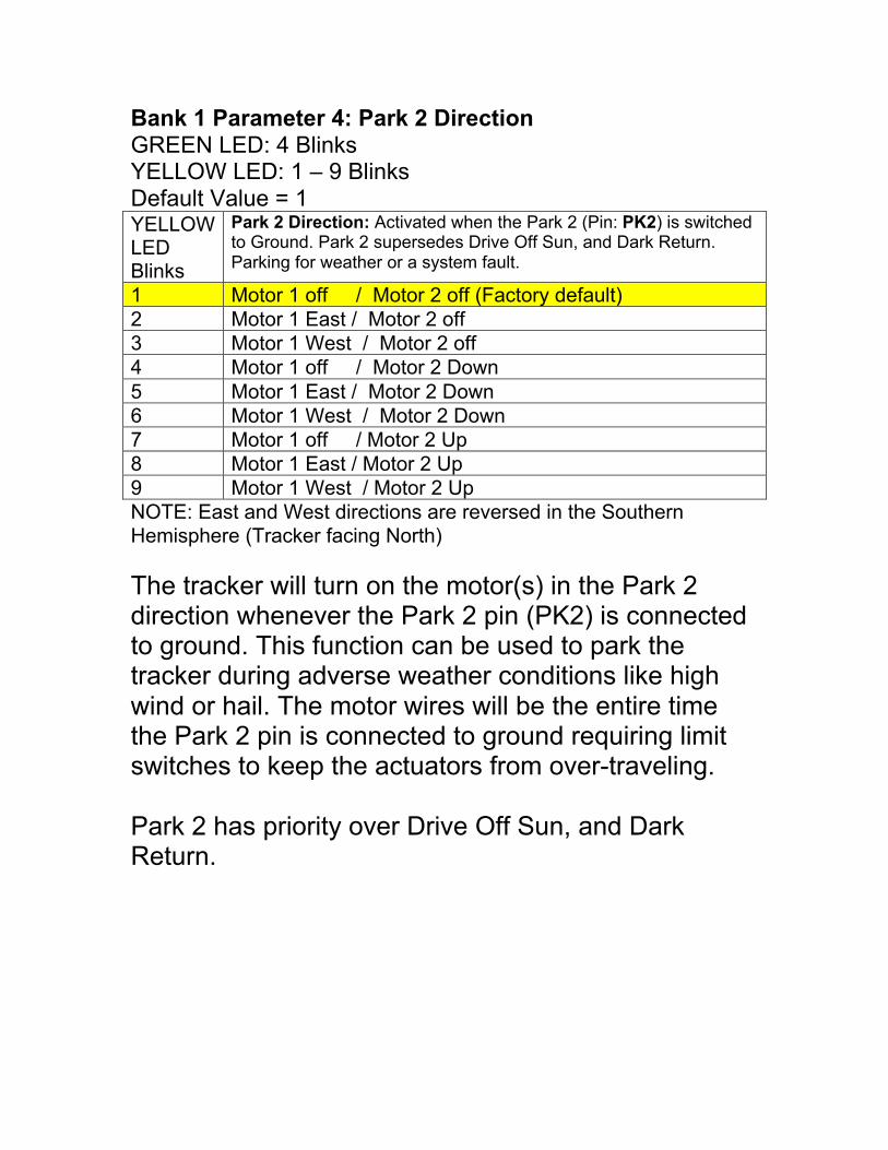
Bank 1 Parameter 4: Park 2 DirectionGREEN LED: 4 BlinksYELLOW LED: 1 – 9 BlinksDefault Value = 1YELLOWLEDBlinks
Park 2 Direction: Activated when the Park 2 (Pin: PK2) is switchedto Ground. Park 2 supersedes Drive Off Sun, and Dark Return.Parking for weather or a system fault.
1 Motor 1 off / Motor 2 off (Factory default)2 Motor 1 East / Motor 2 off3 Motor 1 West / Motor 2 off4 Motor 1 off / Motor 2 Down5 Motor 1 East / Motor 2 Down6 Motor 1 West / Motor 2 Down7 Motor 1 off / Motor 2 Up8 Motor 1 East / Motor 2 Up9 Motor 1 West / Motor 2 UpNOTE: East and West directions are reversed in the SouthernHemisphere (Tracker facing North)
The tracker will turn on the motor(s) in the Park 2direction whenever the Park 2 pin (PK2) is connectedto ground. This function can be used to park thetracker during adverse weather conditions like highwind or hail. The motor wires will be the entire timethe Park 2 pin is connected to ground requiring limitswitches to keep the actuators from over-traveling.
Park 2 has priority over Drive Off Sun, and DarkReturn.
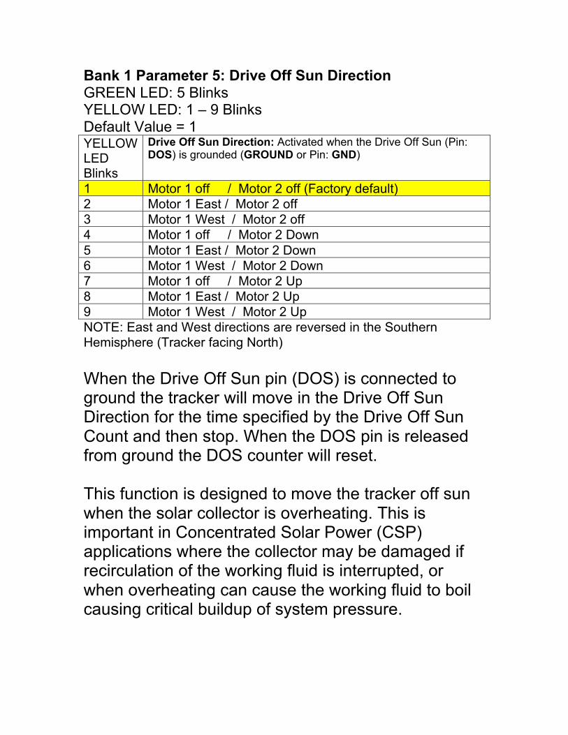
Bank 1 Parameter 5: Drive Off Sun DirectionGREEN LED: 5 BlinksYELLOW LED: 1 – 9 BlinksDefault Value = 1YELLOWLEDBlinks
Drive Off Sun Direction: Activated when the Drive Off Sun (Pin:DOS) is grounded (GROUND or Pin: GND)
1 Motor 1 off / Motor 2 off (Factory default)2 Motor 1 East / Motor 2 off3 Motor 1 West / Motor 2 off4 Motor 1 off / Motor 2 Down5 Motor 1 East / Motor 2 Down6 Motor 1 West / Motor 2 Down7 Motor 1 off / Motor 2 Up8 Motor 1 East / Motor 2 Up9 Motor 1 West / Motor 2 UpNOTE: East and West directions are reversed in the SouthernHemisphere (Tracker facing North)
When the Drive Off Sun pin (DOS) is connected toground the tracker will move in the Drive Off SunDirection for the time specified by the Drive Off SunCount and then stop. When the DOS pin is releasedfrom ground the DOS counter will reset.
This function is designed to move the tracker off sunwhen the solar collector is overheating. This isimportant in Concentrated Solar Power (CSP)applications where the collector may be damaged ifrecirculation of the working fluid is interrupted, orwhen overheating can cause the working fluid to boilcausing critical buildup of system pressure.
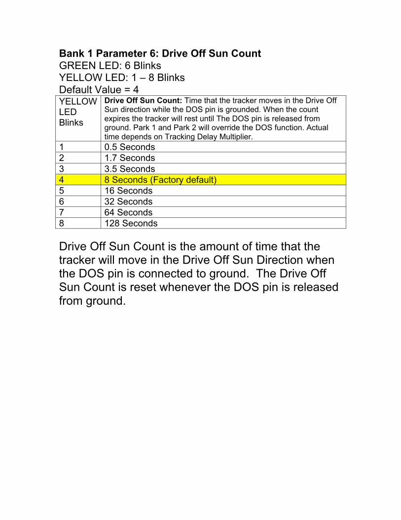
Bank 1 Parameter 6: Drive Off Sun CountGREEN LED: 6 BlinksYELLOW LED: 1 – 8 BlinksDefault Value = 4YELLOWLEDBlinks
Drive Off Sun Count: Time that the tracker moves in the Drive OffSun direction while the DOS pin is grounded. When the countexpires the tracker will rest until The DOS pin is released fromground. Park 1 and Park 2 will override the DOS function. Actualtime depends on Tracking Delay Multiplier.
1 0.5 Seconds2 1.7 Seconds3 3.5 Seconds4 8 Seconds (Factory default)5 16 Seconds6 32 Seconds7 64 Seconds8 128 Seconds
Drive Off Sun Count is the amount of time that thetracker will move in the Drive Off Sun Direction whenthe DOS pin is connected to ground. The Drive OffSun Count is reset whenever the DOS pin is releasedfrom ground.
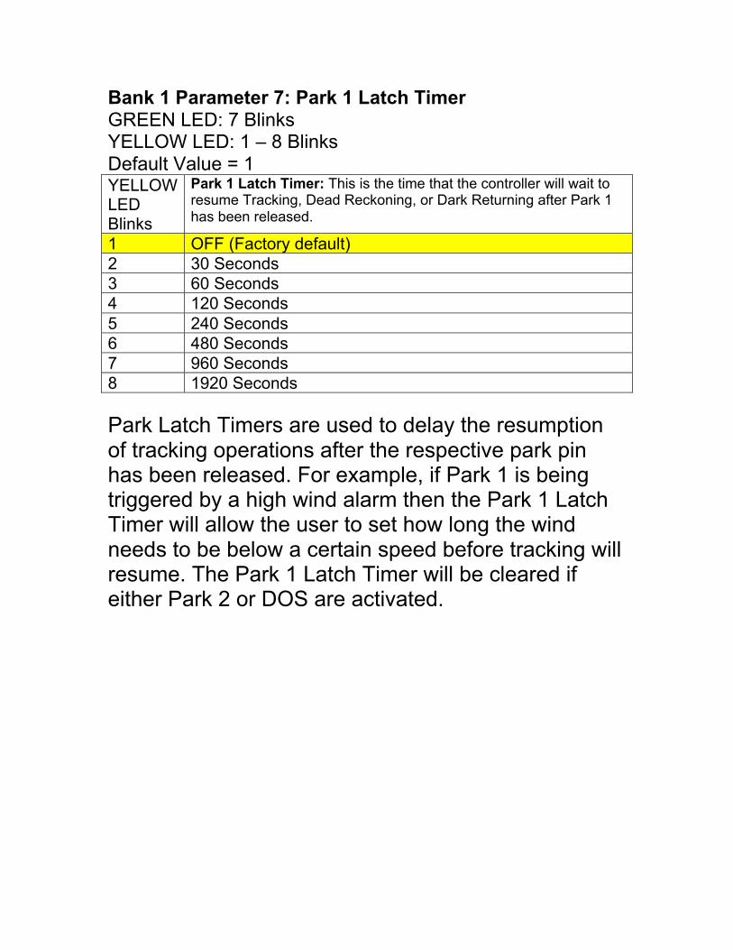
Bank 1 Parameter 7: Park 1 Latch TimerGREEN LED: 7 BlinksYELLOW LED: 1 – 8 BlinksDefault Value = 1YELLOWLEDBlinks
Park 1 Latch Timer: This is the time that the controller will wait toresume Tracking, Dead Reckoning, or Dark Returning after Park 1has been released.
1 OFF (Factory default)2 30 Seconds3 60 Seconds4 120 Seconds5 240 Seconds6 480 Seconds7 960 Seconds8 1920 Seconds
Park Latch Timers are used to delay the resumptionof tracking operations after the respective park pinhas been released. For example, if Park 1 is beingtriggered by a high wind alarm then the Park 1 LatchTimer will allow the user to set how long the windneeds to be below a certain speed before tracking willresume. The Park 1 Latch Timer will be cleared ifeither Park 2 or DOS are activated.
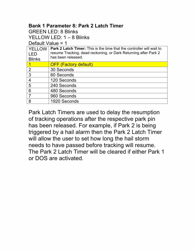
Bank 1 Parameter 8: Park 2 Latch TimerGREEN LED: 8 BlinksYELLOW LED: 1 – 8 BlinksDefault Value = 1YELLOWLEDBlinks
Park 2 Latch Timer: This is the time that the controller will wait toresume Tracking, dead reckoning, or Dark Returning after Park 2has been released.
1 OFF (Factory default)2 30 Seconds3 60 Seconds4 120 Seconds5 240 Seconds6 480 Seconds7 960 Seconds8 1920 Seconds
Park Latch Timers are used to delay the resumptionof tracking operations after the respective park pinhas been released. For example, if Park 2 is beingtriggered by a hail alarm then the Park 2 Latch Timerwill allow the user to set how long the hail stormneeds to have passed before tracking will resume.The Park 2 Latch Timer will be cleared if either Park 1or DOS are activated.
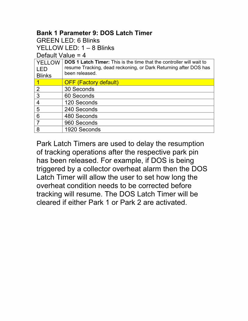
Bank 1 Parameter 9: DOS Latch TimerGREEN LED: 6 BlinksYELLOW LED: 1 – 8 BlinksDefault Value = 4YELLOWLEDBlinks
DOS 1 Latch Timer: This is the time that the controller will wait toresume Tracking, dead reckoning, or Dark Returning after DOS hasbeen released.
1 OFF (Factory default)2 30 Seconds3 60 Seconds4 120 Seconds5 240 Seconds6 480 Seconds7 960 Seconds8 1920 Seconds
Park Latch Timers are used to delay the resumptionof tracking operations after the respective park pinhas been released. For example, if DOS is beingtriggered by a collector overheat alarm then the DOSLatch Timer will allow the user to set how long theoverheat condition needs to be corrected beforetracking will resume. The DOS Latch Timer will becleared if either Park 1 or Park 2 are activated.
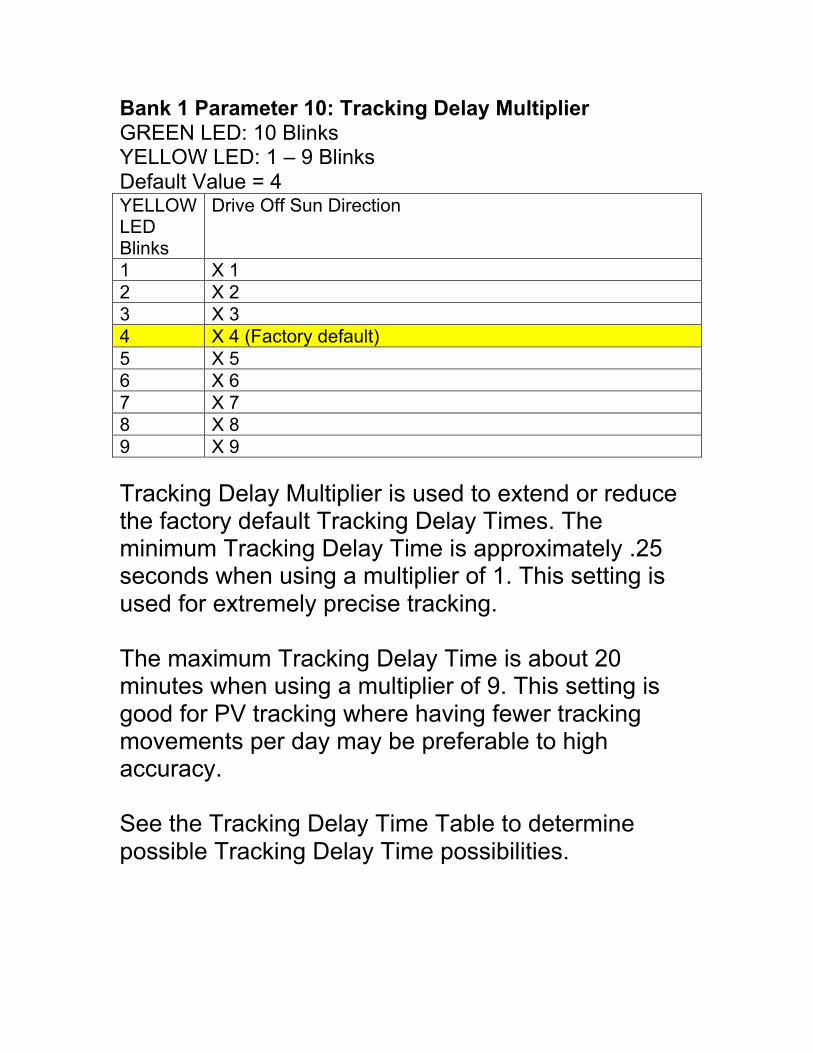
Bank 1 Parameter 10: Tracking Delay MultiplierGREEN LED: 10 BlinksYELLOW LED: 1 – 9 BlinksDefault Value = 4YELLOWLEDBlinks
Drive Off Sun Direction
1 X 12 X 23 X 34 X 4 (Factory default)5 X 56 X 67 X 78 X 89 X 9
Tracking Delay Multiplier is used to extend or reducethe factory default Tracking Delay Times. Theminimum Tracking Delay Time is approximately .25seconds when using a multiplier of 1. This setting isused for extremely precise tracking.
The maximum Tracking Delay Time is about 20minutes when using a multiplier of 9. This setting isgood for PV tracking where having fewer trackingmovements per day may be preferable to highaccuracy.
See the Tracking Delay Time Table to determinepossible Tracking Delay Time possibilities.
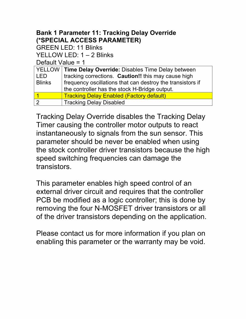
Bank 1 Parameter 11: Tracking Delay Override(*SPECIAL ACCESS PARAMETER)GREEN LED: 11 BlinksYELLOW LED: 1 – 2 BlinksDefault Value = 1YELLOWLEDBlinks
Time Delay Override: Disables Time Delay betweentracking corrections. Caution!! this may cause highfrequency oscillations that can destroy the transistors ifthe controller has the stock H-Bridge output.
1 Tracking Delay Enabled (Factory default)2 Tracking Delay Disabled
Tracking Delay Override disables the Tracking DelayTimer causing the controller motor outputs to reactinstantaneously to signals from the sun sensor. Thisparameter should be never be enabled when usingthe stock controller driver transistors because the highspeed switching frequencies can damage thetransistors.
This parameter enables high speed control of anexternal driver circuit and requires that the controllerPCB be modified as a logic controller; this is done byremoving the four N-MOSFET driver transistors or allof the driver transistors depending on the application.
Please contact us for more information if you plan onenabling this parameter or the warranty may be void.
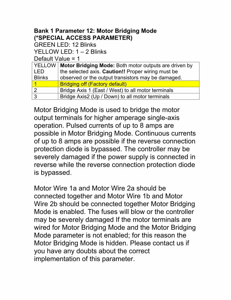
Bank 1 Parameter 12: Motor Bridging Mode(*SPECIAL ACCESS PARAMETER)GREEN LED: 12 BlinksYELLOW LED: 1 – 2 BlinksDefault Value = 1YELLOWLEDBlinks
Motor Bridging Mode: Both motor outputs are driven bythe selected axis. Caution!! Proper wiring must beobserved or the output transistors may be damaged.
1 Bridging off (Factory default)2 Bridge Axis 1 (East / West) to all motor terminals3 Bridge Axis2 (Up / Down) to all motor terminals
Motor Bridging Mode is used to bridge the motoroutput terminals for higher amperage single-axisoperation. Pulsed currents of up to 8 amps arepossible in Motor Bridging Mode. Continuous currentsof up to 8 amps are possible if the reverse connectionprotection diode is bypassed. The controller may beseverely damaged if the power supply is connected inreverse while the reverse connection protection diodeis bypassed.
Motor Wire 1a and Motor Wire 2a should beconnected together and Motor Wire 1b and MotorWire 2b should be connected together Motor BridgingMode is enabled. The fuses will blow or the controllermay be severely damaged If the motor terminals arewired for Motor Bridging Mode and the Motor BridgingMode parameter is not enabled; for this reason theMotor Bridging Mode is hidden. Please contact us ifyou have any doubts about the correctimplementation of this parameter.
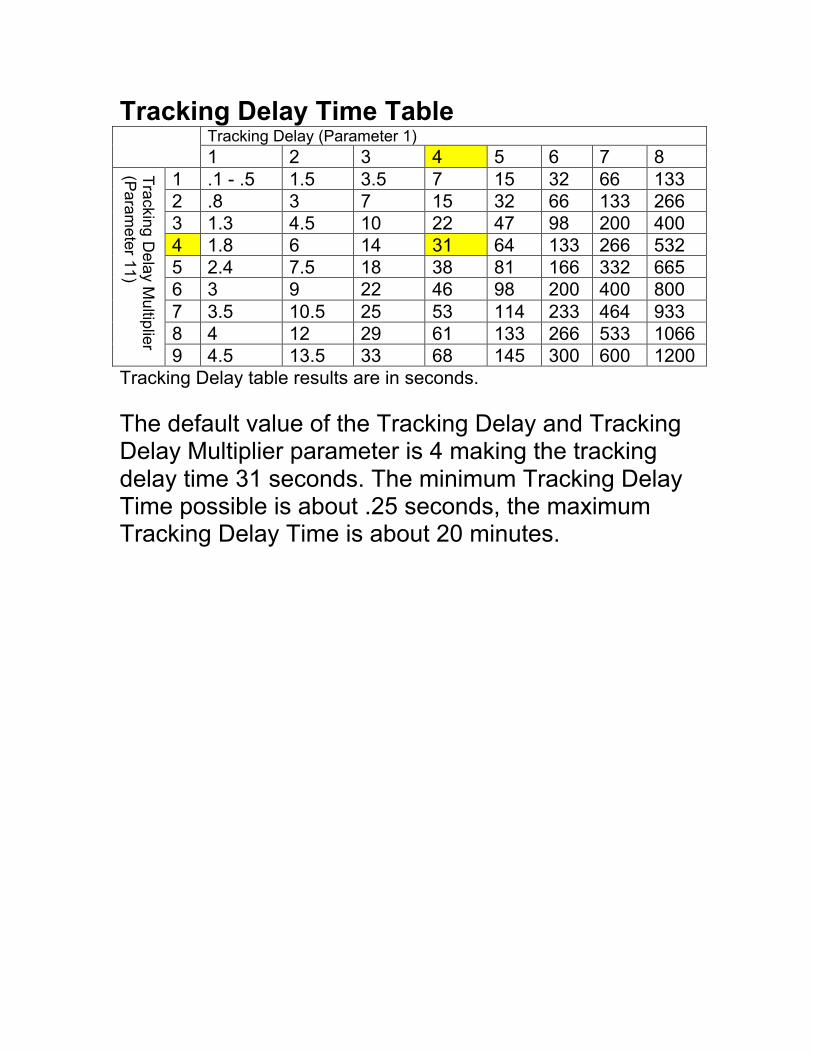
Tracking Delay Time TableTracking Delay (Parameter 1)
1 2 3 4 5 6 7 81 .1 - .5 1.5 3.5 7 15 32 66 1332 .8 3 7 15 32 66 133 2663 1.3 4.5 10 22 47 98 200 4004 1.8 6 14 31 64 133 266 5325 2.4 7.5 18 38 81 166 332 6656 3 9 22 46 98 200 400 8007 3.5 10.5 25 53 114 233 464 9338 4 12 29 61 133 266 533 1066
Tra
ckin
g D
ela
y M
ultip
lier
(Para
mete
r 11)
9 4.5 13.5 33 68 145 300 600 1200Tracking Delay table results are in seconds.
The default value of the Tracking Delay and TrackingDelay Multiplier parameter is 4 making the trackingdelay time 31 seconds. The minimum Tracking DelayTime possible is about .25 seconds, the maximumTracking Delay Time is about 20 minutes.
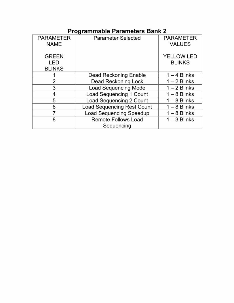
Programmable Parameters Bank 2PARAMETER
NAME
GREENLED
BLINKS
Parameter Selected PARAMETERVALUES
YELLOW LEDBLINKS
1 Dead Reckoning Enable 1 – 4 Blinks2 Dead Reckoning Lock 1 – 2 Blinks3 Load Sequencing Mode 1 – 2 Blinks4 Load Sequencing 1 Count 1 – 8 Blinks5 Load Sequencing 2 Count 1 – 8 Blinks6 Load Sequencing Rest Count 1 – 8 Blinks7 Load Sequencing Speedup 1 – 8 Blinks8 Remote Follows Load
Sequencing1 – 3 Blinks
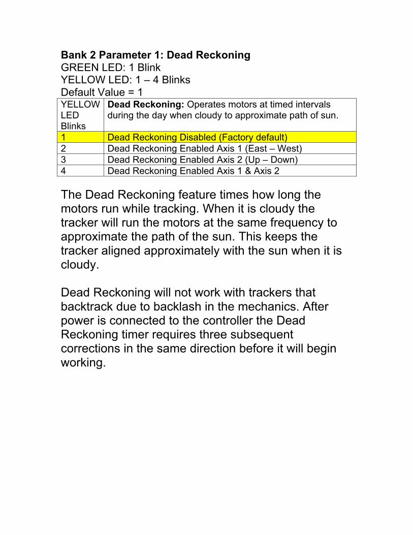
Bank 2 Parameter 1: Dead ReckoningGREEN LED: 1 BlinkYELLOW LED: 1 – 4 BlinksDefault Value = 1YELLOWLEDBlinks
Dead Reckoning: Operates motors at timed intervalsduring the day when cloudy to approximate path of sun.
1 Dead Reckoning Disabled (Factory default)2 Dead Reckoning Enabled Axis 1 (East – West)3 Dead Reckoning Enabled Axis 2 (Up – Down)4 Dead Reckoning Enabled Axis 1 & Axis 2
The Dead Reckoning feature times how long themotors run while tracking. When it is cloudy thetracker will run the motors at the same frequency toapproximate the path of the sun. This keeps thetracker aligned approximately with the sun when it iscloudy.
Dead Reckoning will not work with trackers thatbacktrack due to backlash in the mechanics. Afterpower is connected to the controller the DeadReckoning timer requires three subsequentcorrections in the same direction before it will beginworking.
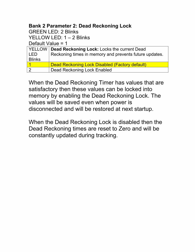
Bank 2 Parameter 2: Dead Reckoning LockGREEN LED: 2 BlinksYELLOW LED: 1 – 2 BlinksDefault Value = 1YELLOWLEDBlinks
Dead Reckoning Lock: Locks the current DeadReckoning times in memory and prevents future updates.
1 Dead Reckoning Lock Disabled (Factory default)2 Dead Reckoning Lock Enabled
When the Dead Reckoning Timer has values that aresatisfactory then these values can be locked intomemory by enabling the Dead Reckoning Lock. Thevalues will be saved even when power isdisconnected and will be restored at next startup.
When the Dead Reckoning Lock is disabled then theDead Reckoning times are reset to Zero and will beconstantly updated during tracking.
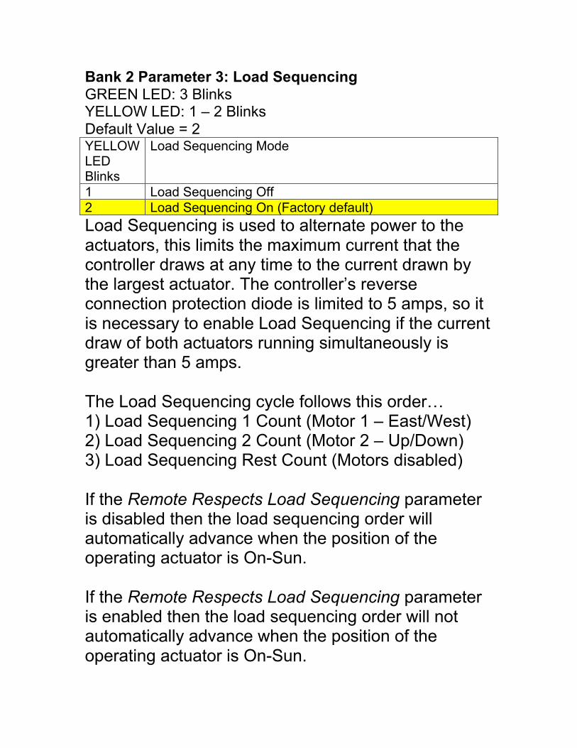
Bank 2 Parameter 3: Load SequencingGREEN LED: 3 BlinksYELLOW LED: 1 – 2 BlinksDefault Value = 2YELLOWLEDBlinks
Load Sequencing Mode
1 Load Sequencing Off2 Load Sequencing On (Factory default)
Load Sequencing is used to alternate power to theactuators, this limits the maximum current that thecontroller draws at any time to the current drawn bythe largest actuator. The controller’s reverseconnection protection diode is limited to 5 amps, so itis necessary to enable Load Sequencing if the currentdraw of both actuators running simultaneously isgreater than 5 amps.
The Load Sequencing cycle follows this order…1) Load Sequencing 1 Count (Motor 1 – East/West)2) Load Sequencing 2 Count (Motor 2 – Up/Down)3) Load Sequencing Rest Count (Motors disabled)
If the Remote Respects Load Sequencing parameteris disabled then the load sequencing order willautomatically advance when the position of theoperating actuator is On-Sun.
If the Remote Respects Load Sequencing parameteris enabled then the load sequencing order will notautomatically advance when the position of theoperating actuator is On-Sun.
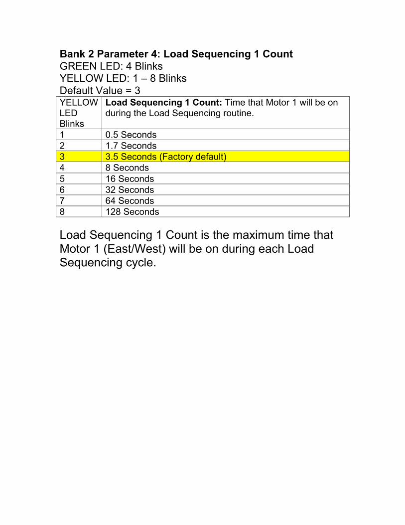
Bank 2 Parameter 4: Load Sequencing 1 CountGREEN LED: 4 BlinksYELLOW LED: 1 – 8 BlinksDefault Value = 3YELLOWLEDBlinks
Load Sequencing 1 Count: Time that Motor 1 will be onduring the Load Sequencing routine.
1 0.5 Seconds2 1.7 Seconds3 3.5 Seconds (Factory default)4 8 Seconds5 16 Seconds6 32 Seconds7 64 Seconds8 128 Seconds
Load Sequencing 1 Count is the maximum time thatMotor 1 (East/West) will be on during each LoadSequencing cycle.

Bank 2 Parameter 5: Load Sequencing 2 CountGREEN LED: 2 BlinksYELLOW LED: 1 – 8 BlinksDefault Value = 3YELLOWLEDBlinks
Load Sequencing 2 Count: Time that Motor 2 will be onduring the Load Sequencing routine.
1 0.5 Seconds2 1.7 Seconds3 3.5 Seconds (Factory default)4 8 Seconds5 16 Seconds6 32 Seconds7 64 Seconds8 128 Seconds
Load Sequencing 2 Count is the time that Motor 2(Up/Down) will be enabled during each LoadSequencing cycle.
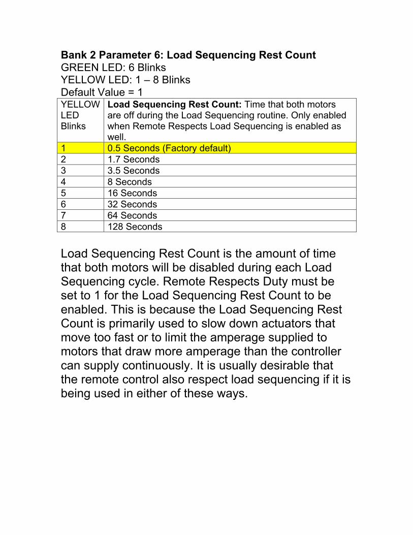
Bank 2 Parameter 6: Load Sequencing Rest CountGREEN LED: 6 BlinksYELLOW LED: 1 – 8 BlinksDefault Value = 1YELLOWLEDBlinks
Load Sequencing Rest Count: Time that both motorsare off during the Load Sequencing routine. Only enabledwhen Remote Respects Load Sequencing is enabled aswell.
1 0.5 Seconds (Factory default)2 1.7 Seconds3 3.5 Seconds4 8 Seconds5 16 Seconds6 32 Seconds7 64 Seconds8 128 Seconds
Load Sequencing Rest Count is the amount of timethat both motors will be disabled during each LoadSequencing cycle. Remote Respects Duty must beset to 1 for the Load Sequencing Rest Count to beenabled. This is because the Load Sequencing RestCount is primarily used to slow down actuators thatmove too fast or to limit the amperage supplied tomotors that draw more amperage than the controllercan supply continuously. It is usually desirable thatthe remote control also respect load sequencing if it isbeing used in either of these ways.
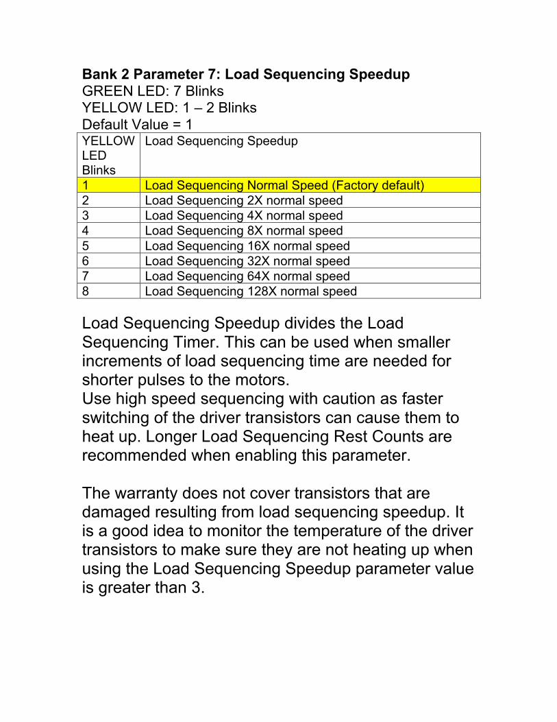
Bank 2 Parameter 7: Load Sequencing SpeedupGREEN LED: 7 BlinksYELLOW LED: 1 – 2 BlinksDefault Value = 1YELLOWLEDBlinks
Load Sequencing Speedup
1 Load Sequencing Normal Speed (Factory default)2 Load Sequencing 2X normal speed3 Load Sequencing 4X normal speed4 Load Sequencing 8X normal speed5 Load Sequencing 16X normal speed6 Load Sequencing 32X normal speed7 Load Sequencing 64X normal speed8 Load Sequencing 128X normal speed
Load Sequencing Speedup divides the LoadSequencing Timer. This can be used when smallerincrements of load sequencing time are needed forshorter pulses to the motors.Use high speed sequencing with caution as fasterswitching of the driver transistors can cause them toheat up. Longer Load Sequencing Rest Counts arerecommended when enabling this parameter.
The warranty does not cover transistors that aredamaged resulting from load sequencing speedup. Itis a good idea to monitor the temperature of the drivertransistors to make sure they are not heating up whenusing the Load Sequencing Speedup parameter valueis greater than 3.
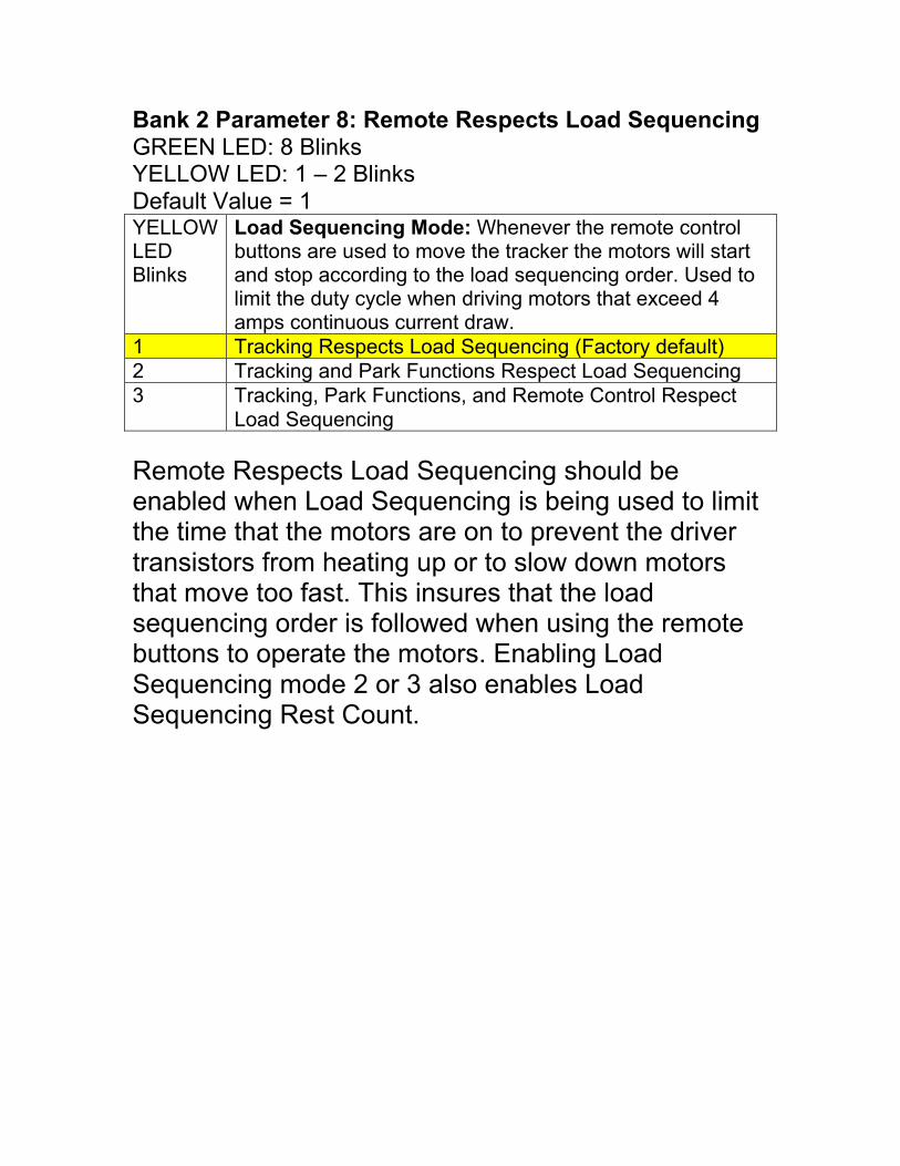
Bank 2 Parameter 8: Remote Respects Load SequencingGREEN LED: 8 BlinksYELLOW LED: 1 – 2 BlinksDefault Value = 1YELLOWLEDBlinks
Load Sequencing Mode: Whenever the remote controlbuttons are used to move the tracker the motors will startand stop according to the load sequencing order. Used tolimit the duty cycle when driving motors that exceed 4amps continuous current draw.
1 Tracking Respects Load Sequencing (Factory default)2 Tracking and Park Functions Respect Load Sequencing3 Tracking, Park Functions, and Remote Control Respect
Load Sequencing
Remote Respects Load Sequencing should beenabled when Load Sequencing is being used to limitthe time that the motors are on to prevent the drivertransistors from heating up or to slow down motorsthat move too fast. This insures that the loadsequencing order is followed when using the remotebuttons to operate the motors. Enabling LoadSequencing mode 2 or 3 also enables LoadSequencing Rest Count.
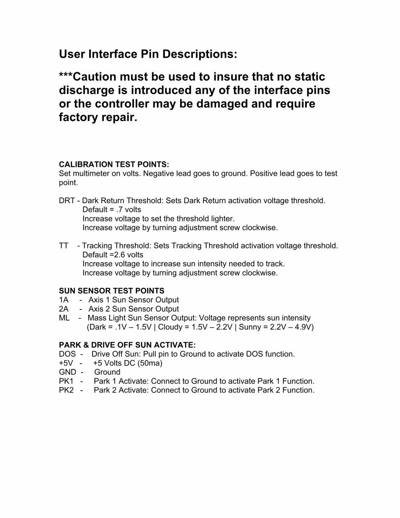
User Interface Pin Descriptions:
***Caution must be used to insure that no staticdischarge is introduced any of the interface pinsor the controller may be damaged and requirefactory repair.
CALIBRATION TEST POINTS:Set multimeter on volts. Negative lead goes to ground. Positive lead goes to testpoint.
DRT - Dark Return Threshold: Sets Dark Return activation voltage threshold.Default = .7 voltsIncrease voltage to set the threshold lighter.Increase voltage by turning adjustment screw clockwise.
TT - Tracking Threshold: Sets Tracking Threshold activation voltage threshold.Default =2.6 voltsIncrease voltage to increase sun intensity needed to track.Increase voltage by turning adjustment screw clockwise.
SUN SENSOR TEST POINTS1A - Axis 1 Sun Sensor Output2A - Axis 2 Sun Sensor OutputML - Mass Light Sun Sensor Output: Voltage represents sun intensity
(Dark = .1V – 1.5V | Cloudy = 1.5V – 2.2V | Sunny = 2.2V – 4.9V)
PARK & DRIVE OFF SUN ACTIVATE:DOS - Drive Off Sun: Pull pin to Ground to activate DOS function.+5V - +5 Volts DC (50ma)GND - GroundPK1 - Park 1 Activate: Connect to Ground to activate Park 1 Function.PK2 - Park 2 Activate: Connect to Ground to activate Park 2 Function.
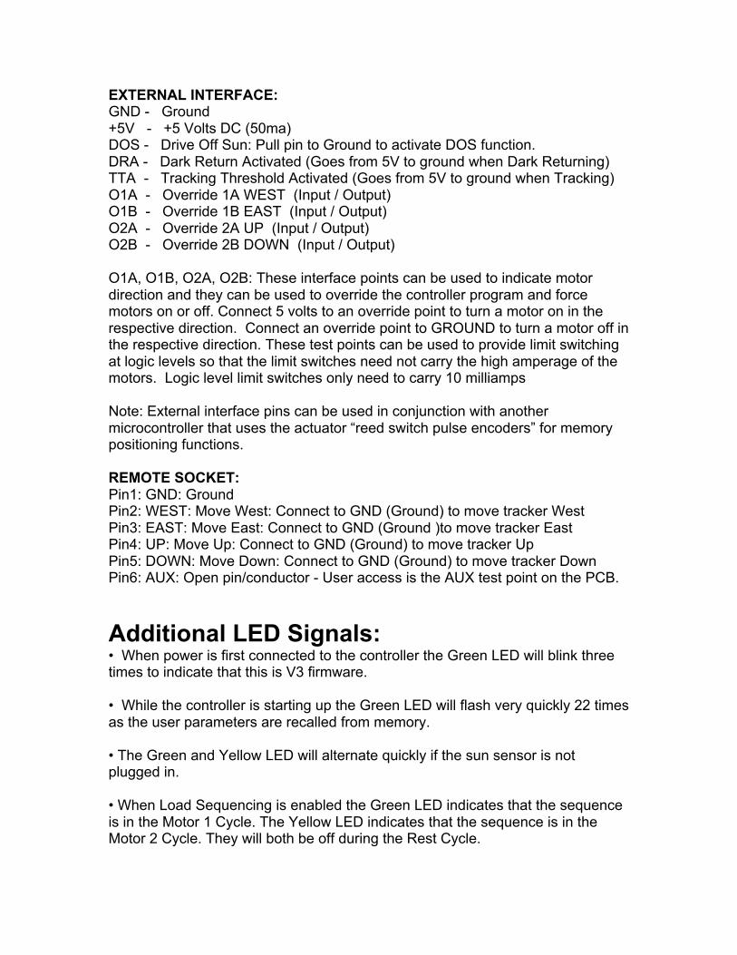
EXTERNAL INTERFACE:GND - Ground+5V - +5 Volts DC (50ma)DOS - Drive Off Sun: Pull pin to Ground to activate DOS function.DRA - Dark Return Activated (Goes from 5V to ground when Dark Returning)TTA - Tracking Threshold Activated (Goes from 5V to ground when Tracking)O1A - Override 1A WEST (Input / Output)O1B - Override 1B EAST (Input / Output)O2A - Override 2A UP (Input / Output)O2B - Override 2B DOWN (Input / Output)
O1A, O1B, O2A, O2B: These interface points can be used to indicate motordirection and they can be used to override the controller program and forcemotors on or off. Connect 5 volts to an override point to turn a motor on in therespective direction. Connect an override point to GROUND to turn a motor off inthe respective direction. These test points can be used to provide limit switchingat logic levels so that the limit switches need not carry the high amperage of themotors. Logic level limit switches only need to carry 10 milliamps
Note: External interface pins can be used in conjunction with anothermicrocontroller that uses the actuator “reed switch pulse encoders” for memorypositioning functions.
REMOTE SOCKET:Pin1: GND: GroundPin2: WEST: Move West: Connect to GND (Ground) to move tracker WestPin3: EAST: Move East: Connect to GND (Ground )to move tracker EastPin4: UP: Move Up: Connect to GND (Ground) to move tracker UpPin5: DOWN: Move Down: Connect to GND (Ground) to move tracker DownPin6: AUX: Open pin/conductor - User access is the AUX test point on the PCB.
Additional LED Signals:• When power is first connected to the controller the Green LED will blink threetimes to indicate that this is V3 firmware.
• While the controller is starting up the Green LED will flash very quickly 22 timesas the user parameters are recalled from memory.
• The Green and Yellow LED will alternate quickly if the sun sensor is notplugged in.
• When Load Sequencing is enabled the Green LED indicates that the sequenceis in the Motor 1 Cycle. The Yellow LED indicates that the sequence is in theMotor 2 Cycle. They will both be off during the Rest Cycle.
• When Load Sequencing is disabled the Green LED will flash periodically toindicate that the controller is on.
• When Park 1 is enabled the Green LED will blink quickly continuously.
• When Park 2 is enabled the Yellow LED will blink quickly continuously.
• When DOS is enabled the Green & Yellow LED will blink twice quickly thenrepeat.
• When Tracking has been disabled by Remote Control the Green and YellowLED will flash 3 times followed by a short pause and then repeat.
HINTS:Disabling tracking to facilitate control of actuators with an external circuit:1 - Program Park1 to have no direction. Parameter 3(Green LED = 3 blinks)Value = 1 (Yellow LED = 1 blink).
2 - Connect Park1 pin is to ground to disable Dark Return, Park2 and DOS andTracking functions.
3 - Now use the Remote Control inputs to control tracker motion.
Copyright 2005-2012 By Justin BruenHeliotrack,LLC
32990 Poudre CanyonBellvue, Co 80512
Troubleshooting tips:
• Symptom : The parameter LED flashes quick 15 times, then holdsfor a moment, then repeats but controller never properly powersup.• Cause : One or both motor terminals may be shorted. When themotor terminals are energized the power supply will fold at whichpoint the controller will power down and shut off current to themotor terminals, the power will come back up and the controllerwill begin the initialization sequence again only to repeat theprocess.

Notes: