high performance modular door - rite-hite
TRANSCRIPT
FASTRAX®
HIGH PERFORMANCE MODULAR DOOR
PRINTED IN U.S.A. Publication No. FasTraxG
email: [email protected] July 2011
This Manual Covers Doors Shipped = > 8/16/2010. Added Encoder, fabric shroud and updated radials.
Refer to FasTraxE for doors prior.
This manual to remain with the door:
Date Installed:____________________
This Manual Covers Doors Shipped = > 8/16/2010. Added Encoder, fabric shroud and updated radials.
Refer to FasTraxE for doors prior.
2 PUB. NO. FASTRAXG JULY 2011
FASTRAX®
TABLE OF CONTENTSCHAPTER 1DOOR JAMB . . . . . . . . . . . . . . . . . . . . . . . . . . . . . . . . . . . . . . . . . . . .3
CHAPTER 2LOWER TRACK INSTALLATION . . . . . . . . . . . . . . . . . . . . . . . . . . . .4
CHAPTER 3DRIVE TUBE INSTALLATION . . . . . . . . . . . . . . . . . . . . . . . . . . . . . .6
MOTOR / ENCODER INSTALLATION . . . . . . . . . . . . . . . . . . . . . . . .7
CHAPTER 4UPPER TRACK INSTALLATION . . . . . . . . . . . . . . . . . . . . . . . . . . . .8
CHAPTER 5CURTAIN INSTALLATION . . . . . . . . . . . . . . . . . . . . . . . . . . . . . . . .14
CHAPTER 6DRIVE SHROUD / LABELS / I-ZONE . . . . . . . . . . . . . . . . . . . . . . . .15
CHAPTER 7ELECTRICAL INSTALLATION . . . . . . . . . . . . . . . . . . . . . . . . . . . . . .16
i-COMM LOGIC TABLE . . . . . . . . . . . . . . . . . . . . . . . . . . . . . . . . . . .18
ENCODER SETUP . . . . . . . . . . . . . . . . . . . . . . . . . . . . . . . . . . . . . . .19
CHAPTER 8OPERATING INSTRUCTIONS / FINAL CHECKLIST . . . . . . . . . . . .20
CHAPTER 9POLY LUMBER INSTALLATION . . . . . . . . . . . . . . . . . . . . . . . . . . . .22
SHROUD INSTALLATION . . . . . . . . . . . . . . . . . . . . . . . . . . . . . . . . .23
CHAIN HOIST / WELD PLATE INSTALLATION . . . . . . . . . . . . . . . .24
CHAPTER 10MAINTENANCE PROCEDURES . . . . . . . . . . . . . . . . . . . . . . . . . . . .27
INVERTER PARAMETERS . . . . . . . . . . . . . . . . . . . . . . . . . . . . . . . .28
TROUBLESHOOTING . . . . . . . . . . . . . . . . . . . . . . . . . . . . . . . . . . . .32
CHAPTER 11ELECTRICAL DRAWINGS . . . . . . . . . . . . . . . . . . . . . . . . . . . . . . . . .34
CHAPTER 12EXPLODED VIEWS WITH PARTS LIST . . . . . . . . . . . . . . . . . . . . . .39
CHAPTER 13ARCHITECTURAL DRAWINGS . . . . . . . . . . . . . . . . . . . . . . . . . . . . .47
WARRANTY . . . . . . . . . . . . . . . . . . . . . . . . . . . . . . . . . . . . . back page
SPECIAL FEATURES
- i-COMM™ Universal Controller - Adjustable Speeds
- Heavy-Duty Industrial Materials - Encoder Positioning
- No Springs, Pulleys or Weights - Virtual Vision
- InsulMax Curtain w/Auto Re-feed™ - Powder Coated Materials
- I-Zone™ Area Detection System - Soft-Edge™ Technology
- Flexible “You Build It” Track Design - High Pressure Capability
- DuraMax Curtain w/Auto Re-feed™
RECOMMENDED SERVICE PARTS
Bumper, Rubber, Motor 15250081 (2)
Fuse, 1 Amp, 250V, Time Delay 51000002 (2)
Fuse, 2 Amp, 250V, Time Delay 51000005 (2)
Kit, Drive Sphere, Qty 10 53700561 (2)
Photoeye Source 53700702 (1)
Photoeye Receiver 53700703 (1)
Kit, Encoder 53700792 (1)
NOTICE TO USER
Our mission is to “Improve Industrial Safety, Security and
Productivity Worldwide Through Quality and Innovation.”
Thank you for purchasing the FasTrax® door from RITE-HITE
DOORS, INC. The FasTrax door is a unique fabric door that can
be transformed to fit most opening configurations while helping
to keep different atmospheres separate.
This manual should be thoroughly read and understood before
beginning the installation, operation or servicing of this door.
This owners manual MUST be stored near the door.
Complete final checklist prior to leaving site.
Refer to partslist manual for exploded views and part numbers.
RITE-HITE DOORS, INC. reserves the right to modify the
electrical and architectural drawings in this manual as well as
the actual parts used on this product are subject to
manufacturing changes and may be different than shown in this
manual. Due to unique circumstances with varying
requirements, separate prints may be included with the unit.
The information contained in this manual will allow you to
operate and maintain the door in a manner which will insure
maximum life and trouble free operation. The serial # for your
door is on a label located on the side of the control box and side
track, Figure 17.1.
Your local RITE-HITE DOORS, INC. Representative provides
the Planned Maintenance Program (P.M.P.) which can be fitted
to your specific operation. If any procedures for the installation,
operation or maintenance of the FasTrax have been left out of
this manual, are not complete or have suggestions, contact
RITE-HITE DOORS, INC. Technical Support at 1-563-589-2722.
RITE-HITE DOORS, INC. are covered by one or more of the
following U.S. patents, including patents applied for, pending, or
issued:
5,203,175, 5,329,781, 5,353,859, 5,392,836, 5,408,789
5,450,890, 5,542,463, 5,579,820, 5,601,134, 5,638,883,
5,655,591, 5,730,197, 5,743,317, 5,794,678, 5,887,385,
5,915,448, 5,944,086, 5,957,187, 6,042,158, 6,089,305,
6,098,695, 6,145,571, 6,148,897, 6,192,960, 6,321,822,
6,325,195, 6,330,763, 6,352,097, 6,360,487, 6,481,487,
6,574,832, 6,598,648, 6,612,357, 6,615,898, 6,659,158,
6,688,374, 6,698,490, 6,766,562, 6,901,703, 6,923,238,
6,926,061, 6,942,000, 6,964,289, 7,034,682, 7,045,764,
7,111,661, 7,114,753, 7,151,450, 7,748,431
PUB. NO. FASTRAXG JULY 2011 3
FASTRAX®
CHAPTER 1 - DOOR JAMB
It is important to verify the following basic
information before starting with the installation.
1. Alternate dimensions in brackets are in [millimeters].
2. Make sure that you are working at the correct location and
that you have the required work permits.
3. Inspect the site to make sure that there are no overhead
obstructions (sprinkler pipes, HVAC systems, electrical
supply lines, etc.) that might interfere with the installation.
4. Detour material handling equipment during the installation.
5. Make sure that the correct electrical power is supplied to
the door control box and can be shut off without
interfering with other plant operations.
6. Install optional equipment after verifying door operation.
7. To verify proper installation, use Checklist on Page 21.
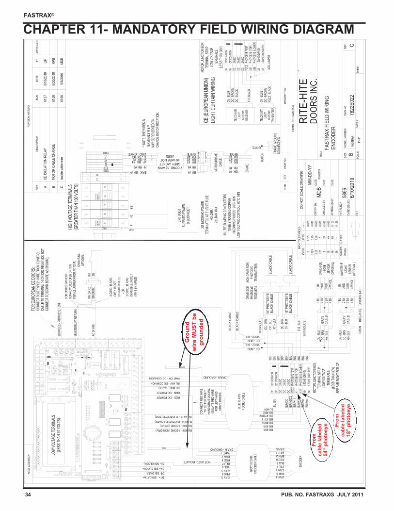
NOTE: Electrical prints included in the parts or control box supersede any prints included in this owners manual on Pages 34 - 38. Always check for electrical prints.
INSTALLATION TOOLS REQUIRED
- 25’ [7620] Tape measure - Hydro level
- 6’ [1829] Carpenters level - Ladder (6’-8’) [1829 - 2438]
- Scissors Lift - Plumb Bob
- “C” Clamps - Hammer Drill
- Drill (cordless or electric) - Drill Bits
- Phillips Bit for Drill - Straight Edge
- Wire Strippers - 5/16” [10] Nut Driver
- Small Straight/Phillips Screwdrivers
- Allen Wrench Set (2MM, 1/8” [3] & 5/32” [4])
- 7/16” [11], 1/2” [13], 9/16” [14], 3/4” [19] Socket/wrench
Make sure to barricade the door opening on both sides to prevent
unauthorized use until the door has been completely installed.
CAUTION ! ! !!RECOMMENDED MOUNTING FASTENERS
Wall Fastener
Wood Lower Track - 3/8" [10] thru-bolt at top, middle, and bottom. 5/16" x 1-1/2" [8x38] lag screws at all other fastener positions.Upper Track - 5/16" x 1-1/2" [8x38] lag screws at all positions.
Wood Lower Track - 3/8" [10] thru-bolt at top, middle, and bottom. /Steel 5/16" x 1-1/2" [8x38] lag screws at all other fastener positions.
Upper Track - 5/16" x 1-1/2" [8x38] lag screws at all positions.
Wood Lower Track - 3/8" [10] thru-bolt or 3/8" [10] masonry anchor
/Masonry positions.at top, middle, and bottom.5/16" x 1-1/2" [8x38] lag screws at all other fastener positions.
Steel 1. 3/8" [10] thru-bolt.2. 3/8" [10] drill and tap (material must be 5/16" [8] min.).3. 3/8" [10] drive self tap/drill screws (1/4" – 14) [6].4. Weld, lower track is aluminum, only weld if steel jamb
option is included or provided by others.
High Side
3.1
For space clearance
requirements, see
Architectural drawings
on Pages 47 - 51.
Low Side
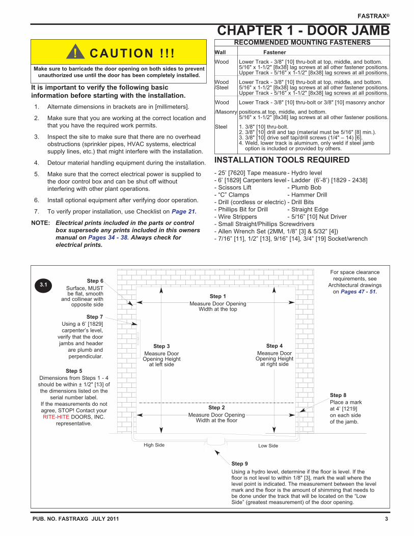
Step 1
Measure Door OpeningWidth at the top
Step 2
Measure Door OpeningWidth at the floor
Step 3
Measure DoorOpening Height
at left side
Step 4
Measure DoorOpening Height
at right side
Step 6
Surface, MUSTbe flat, smooth
and collinear withopposite side
Step 7
Using a 6’ [1829]
carpenter’s level,
verify that the door
jambs and header
are plumb and
perpendicular.
Step 5
Dimensions from Steps 1 - 4
should be within ± 1/2" [13] of
the dimensions listed on the
serial number label.
If the measurements do not
agree, STOP! Contact your
RITE-HITE DOORS, INC.
representative.
Step 8
Place a mark
at 4’ [1219]
on each side
of the jamb.
Step 9
Using a hydro level, determine if the floor is level. If thefloor is not level to within 1/8" [3], mark the wall where thelevel point is indicated. The measurement between the levelmark and the floor is the amount of shimming that needs tobe done under the track that will be located on the “LowSide” (greatest measurement) of the door opening.
4 PUB. NO. FASTRAXG JULY 2011
FASTRAX®
CHAPTER 2 - LOWER TRACK INSTALLATION
Step 2
Step 1
Step 3
4.1
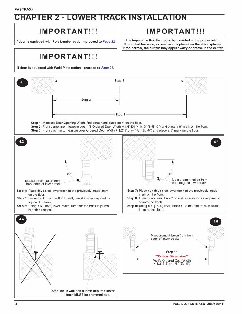
Step 4: Place drive side lower track at the previously made mark
on the floor.
Step 5: Lower track must be 90° to wall, use shims as required to
square the track.
Step 6: Using a 6’ [1829] level, make sure that the track is plumb
in both directions.
4.2
90°
Measurement taken fromfront edge of lower track
Step 7: Place non-drive side lower track at the previously made
mark on the floor.
Step 8: Lower track must be 90° to wall, use shims as required to
square the track.
Step 9: Using a 6’ [1829] level, make sure that the track is plumb
in both directions.
90°
Measurement taken fromfront edge of lower track
4.3
4.4
Step 10: If wall has a jamb cap, the lower
track MUST be shimmed out.
It is imperative that the tracks be mounted at the proper width.
If mounted too wide, excess wear is placed on the drive spheres.
If too narrow, the curtain may appear wavy or crease in the center.
IMPORTANT!!!
Measurement taken from frontedge of lower tracks
4.5
Step 11
**Critical Dimension**
Verify Ordered Door Width+ 1/2" [13] (+ 1/8" [3], -0")
Step 1: Measure Door Opening Width, find center and place mark on the floor.
Step 2: From centerline, measure over 1/2 Ordered Door Width + 1/4” [6] (+ 1/16" [1.5], -0") and place a 6” mark on the floor.
Step 3: From this mark, measure over Ordered Door Width + 1/2" [13] (+ 1/8" [3], -0") and place a 6” mark on the floor.
If door is equipped with Poly Lumber option - proceed to Page 22.
IMPORTANT!!!
If door is equipped with Weld Plate option - proceed to Page 25.
IMPORTANT!!!
PUB. NO. FASTRAXG JULY 2011 5
FASTRAX®
CHAPTER 2 - LOWER TRACK INSTALLATION
5.2
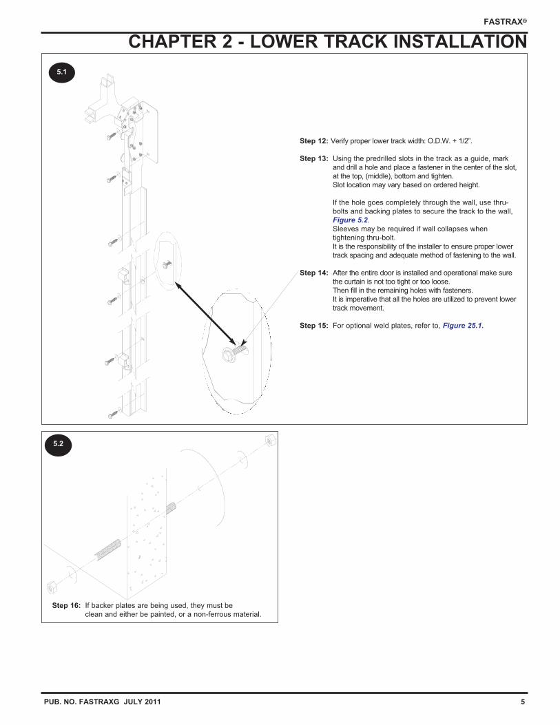
Step 16: If backer plates are being used, they must be
clean and either be painted, or a non-ferrous material.
5.1
Step 12: Verify proper lower track width: O.D.W. + 1/2”.
Step 13: Using the predrilled slots in the track as a guide, mark
and drill a hole and place a fastener in the center of the slot,
at the top, (middle), bottom and tighten.
Slot location may vary based on ordered height.
If the hole goes completely through the wall, use thru-
bolts and backing plates to secure the track to the wall,
Figure 5.2.
Sleeves may be required if wall collapses when
tightening thru-bolt.
It is the responsibility of the installer to ensure proper lower
track spacing and adequate method of fastening to the wall.
Step 14: After the entire door is installed and operational make sure
the curtain is not too tight or too loose.
Then fill in the remaining holes with fasteners.
It is imperative that all the holes are utilized to prevent lower
track movement.
Step 15: For optional weld plates, refer to, Figure 25.1.
6 PUB. NO. FASTRAXG JULY 2011
FASTRAX®
CHAPTER 3 - DRIVE TUBE INSTALLATION
6.2
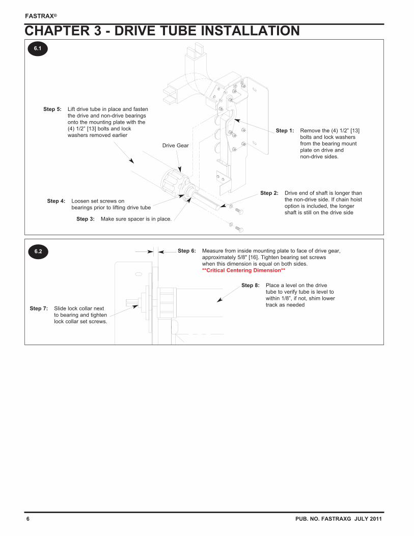
Drive Gear
6.1
Step 1: Remove the (4) 1/2” [13]
bolts and lock washers
from the bearing mount
plate on drive and
non-drive sides.
Step 3: Make sure spacer is in place.
Step 4: Loosen set screws on
bearings prior to lifting drive tube
Step 5: Lift drive tube in place and fasten
the drive and non-drive bearings
onto the mounting plate with the
(4) 1/2” [13] bolts and lock
washers removed earlier
Step 2: Drive end of shaft is longer than
the non-drive side. If chain hoist
option is included, the longer
shaft is still on the drive side
Step 6: Measure from inside mounting plate to face of drive gear,
approximately 5/8" [16]. Tighten bearing set screws
when this dimension is equal on both sides.
**Critical Centering Dimension**
Step 7: Slide lock collar next
to bearing and tighten
lock collar set screws.
Step 8: Place a level on the drive
tube to verify tube is level to
within 1/8”, if not, shim lower
track as needed
PUB. NO. FASTRAXG JULY 2011 7
FASTRAX®
CHAPTER 3 - MOTOR / ENCODER INSTALLATION
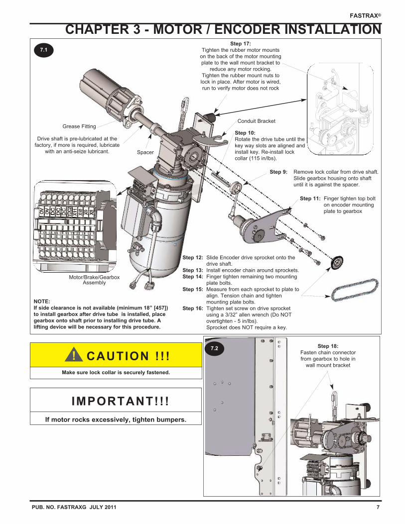
Motor/Brake/GearboxAssembly
Drive shaft is pre-lubricated at the
factory, if more is required, lubricate
with an anti-seize lubricant.
Conduit Bracket
Spacer
NOTE:
If side clearance is not available (minimum 18” [457])
to install gearbox after drive tube is installed, place
gearbox onto shaft prior to installing drive tube. A
lifting device will be necessary for this procedure.
Grease Fitting
7.1
Make sure lock collar is securely fastened.
CAUTION ! ! !!
If motor rocks excessively, tighten bumpers.
IMPORTANT!!!
Step 11: Finger tighten top bolt
on encoder mounting
plate to gearbox
Step 10:
Rotate the drive tube until the
key way slots are aligned and
install key. Re-install lock
collar (115 in/lbs).
Step 9: Remove lock collar from drive shaft.
Slide gearbox housing onto shaft
until it is against the spacer.
Step 17:
Tighten the rubber motor mounts
on the back of the motor mounting
plate to the wall mount bracket to
reduce any motor rocking.
Tighten the rubber mount nuts to
lock in place. After motor is wired,
run to verify motor does not rock
Step 12: Slide Encoder drive sprocket onto the
drive shaft.
Step 13: Install encoder chain around sprockets.
Step 14: Finger tighten remaining two mounting
plate bolts.
Step 15: Measure from each sprocket to plate to
align. Tension chain and tighten
mounting plate bolts.
Step 16: Tighten set screw on drive sprocket
using a 3/32” allen wrench (Do NOT
overtighten - 5 in/lbs).
Sprocket does NOT require a key.
Step 18:
Fasten chain connector
from gearbox to hole in
wall mount bracket
7.2
8 PUB. NO. FASTRAXG JULY 2011
FASTRAX®
CHAPTER 4 - UPPER TRACK RADIAL ONLY
8.1
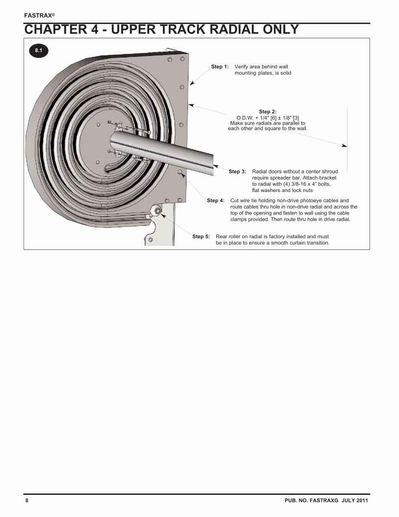
Step 1: Verify area behind wall
mounting plates, is solid
Step 5: Rear roller on radial is factory installed and must
be in place to ensure a smooth curtain transition.
Step 2:
O.D.W. + 1/4" [6] ± 1/8” [3]Make sure radials are parallel to
each other and square to the wall.
Step 3: Radial doors without a center shroud
require spreader bar. Attach bracket
to radial with (4) 3/8-16 x 4” bolts,
flat washers and lock nuts
Step 4: Cut wire tie holding non-drive photoeye cables and
route cables thru hole in non-drive radial and across the
top of the opening and fasten to wall using the cable
clamps provided. Then route thru hole in drive radial.
PUB. NO. FASTRAXG JULY 2011 9
FASTRAX®
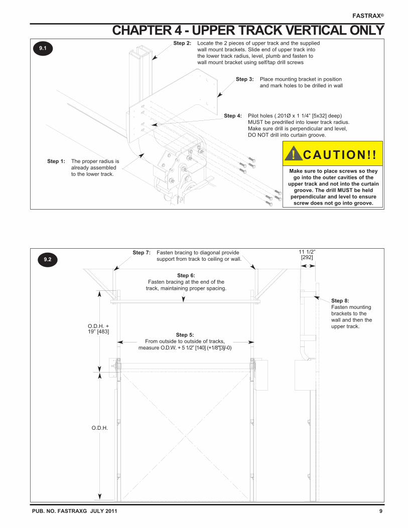
CHAPTER 4 - UPPER TRACK VERTICAL ONLY
O.D.H. +19” [483]
O.D.H.
11 1/2”[292]
Step 5:
From outside to outside of tracks,
measure O.D.W. + 5 1/2” [140] (+1/8"[3]/-0)
Step 6:
Fasten bracing at the end of the
track, maintaining proper spacing.
9.1
9.2
Step 2: Locate the 2 pieces of upper track and the supplied
wall mount brackets. Slide end of upper track into
the lower track radius, level, plumb and fasten to
wall mount bracket using self/tap drill screws
Step 3: Place mounting bracket in position
and mark holes to be drilled in wall
Step 4: Pilot holes (.201Ø x 1 1/4” [5x32] deep)
MUST be predrilled into lower track radius.
Make sure drill is perpendicular and level,
DO NOT drill into curtain groove.
Step 1: The proper radius is
already assembled
to the lower track.
Step 7: Fasten bracing to diagonal provide
support from track to ceiling or wall.
Step 8:
Fasten mounting
brackets to the
wall and then the
upper track.
Make sure to place screws so they
go into the outer cavities of the
upper track and not into the curtain
groove. The drill MUST be held
perpendicular and level to ensure
screw does not go into groove.
CAUTION!!!
10 PUB. NO. FASTRAXG JULY 2011
FASTRAX®
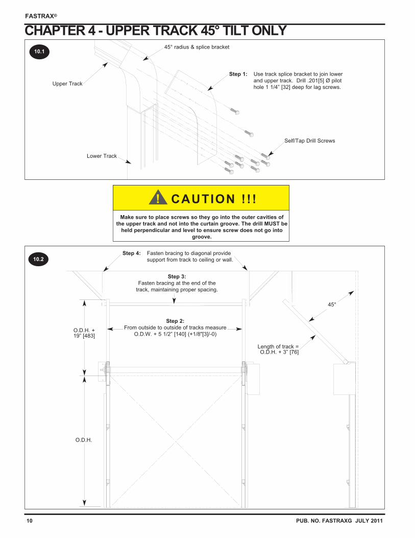
CHAPTER 4 - UPPER TRACK 45° TILT ONLY
O.D.H. +19” [483]
O.D.H.
Length of track =O.D.H. + 3” [76]
45°
Step 2:
From outside to outside of tracks measure
O.D.W. + 5 1/2” [140] (+1/8"[3]/-0)
10.2
Lower Track
Self/Tap Drill Screws
45° radius & splice bracket10.1
Step 1: Use track splice bracket to join lower
and upper track. Drill .201[5] Ø pilot
hole 1 1/4” [32] deep for lag screws.Upper Track
Make sure to place screws so they go into the outer cavities of
the upper track and not into the curtain groove. The drill MUST be
held perpendicular and level to ensure screw does not go into
groove.
CAUTION ! ! !!
Step 3:
Fasten bracing at the end of the
track, maintaining proper spacing.
Step 4: Fasten bracing to diagonal provide
support from track to ceiling or wall.
PUB. NO. FASTRAXG JULY 2011 11
FASTRAX®
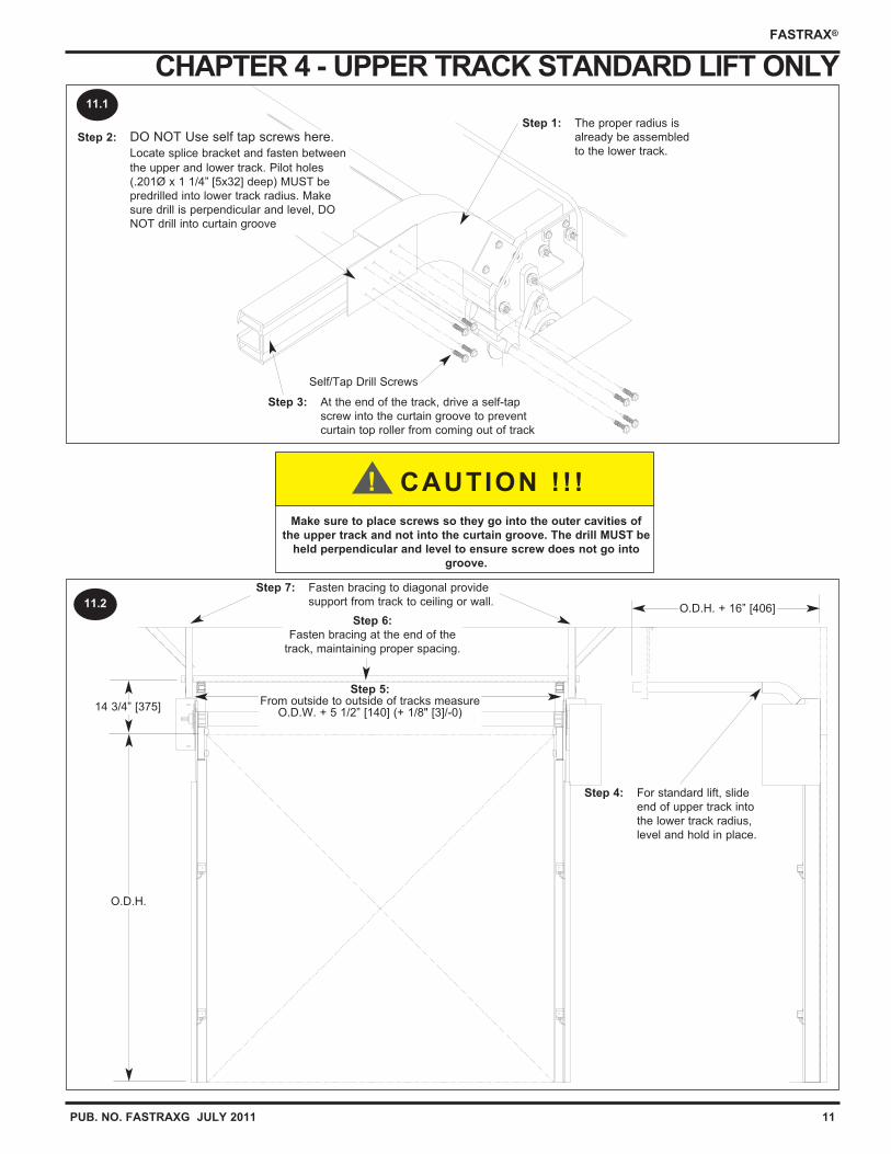
CHAPTER 4 - UPPER TRACK STANDARD LIFT ONLY
Step 5:From outside to outside of tracks measure
O.D.W. + 5 1/2” [140] (+ 1/8" [3]/-0)14 3/4” [375]
O.D.H.
O.D.H. + 16” [406]
Step 1: The proper radius is
already be assembled
to the lower track.
Self/Tap Drill Screws
11.2
11.1
Step 3: At the end of the track, drive a self-tap
screw into the curtain groove to prevent
curtain top roller from coming out of track
Step 2: DO NOT Use self tap screws here.
Locate splice bracket and fasten between
the upper and lower track. Pilot holes
(.201Ø x 1 1/4” [5x32] deep) MUST be
predrilled into lower track radius. Make
sure drill is perpendicular and level, DO
NOT drill into curtain groove
Make sure to place screws so they go into the outer cavities of
the upper track and not into the curtain groove. The drill MUST be
held perpendicular and level to ensure screw does not go into
groove.
CAUTION ! ! !!
Step 6:
Fasten bracing at the end of the
track, maintaining proper spacing.
Step 7: Fasten bracing to diagonal provide
support from track to ceiling or wall.
Step 4: For standard lift, slide
end of upper track into
the lower track radius,
level and hold in place.
12 PUB. NO. FASTRAXG JULY 2011
FASTRAX®
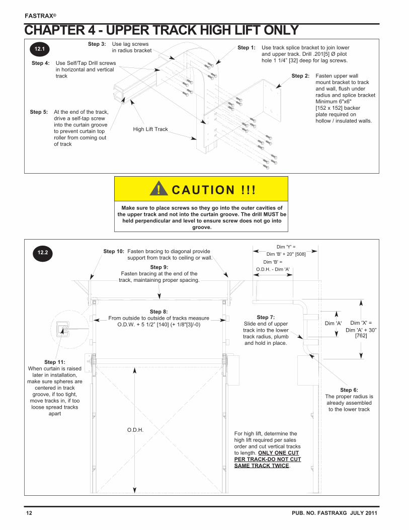
CHAPTER 4 - UPPER TRACK HIGH LIFT ONLY
Step 8:
From outside to outside of tracks measure
O.D.W. + 5 1/2” [140] (+ 1/8"[3]/-0)
O.D.H.
Dim 'X' =
Dim 'A' + 30”[762]
Dim 'Y' =
Dim 'B' + 20'' [508]
Dim 'B' =
O.D.H. - Dim 'A'
High Lift Track
Step 2: Fasten upper wall
mount bracket to track
and wall, flush under
radius and splice bracket
Minimum 6"x6"
[152 x 152] backer
plate required on
hollow / insulated walls.
Dim 'A'
For high lift, determine the
high lift required per sales
order and cut vertical tracks
to length. ONLY ONE CUT
PER TRACK-DO NOT CUT
SAME TRACK TWICE.
12.2
12.1 Step 1: Use track splice bracket to join lower
and upper track. Drill .201[5] Ø pilot
hole 1 1/4” [32] deep for lag screws.
Step 3: Use lag screws
in radius bracket
Step 4: Use Self/Tap Drill screws
in horizontal and vertical
track
Make sure to place screws so they go into the outer cavities of
the upper track and not into the curtain groove. The drill MUST be
held perpendicular and level to ensure screw does not go into
groove.
CAUTION ! ! !!
Step 9:
Fasten bracing at the end of the
track, maintaining proper spacing.
Step 10: Fasten bracing to diagonal provide
support from track to ceiling or wall.
Step 11:
When curtain is raised
later in installation,
make sure spheres are
centered in track
groove, if too tight,
move tracks in, if too
loose spread tracks
apart
Step 5: At the end of the track,
drive a self-tap screw
into the curtain groove
to prevent curtain top
roller from coming out
of track
Step 7:
Slide end of upper
track into the lower
track radius, plumb
and hold in place.
Step 6:
The proper radius is
already assembled
to the lower track

PUB. NO. FASTRAXG JULY 2011 13
FASTRAX®
RITE-HITE DOORS NOTES PAGE
This page intentional left blank.
14 PUB. NO. FASTRAXG JULY 2011
FASTRAX®
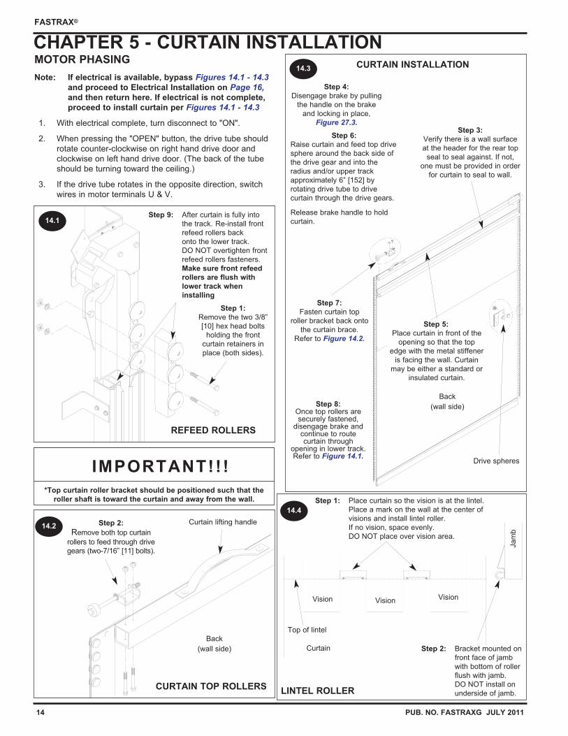
MOTOR PHASING
Note: If electrical is available, bypass Figures 14.1 - 14.3and proceed to Electrical Installation on Page 16, and then return here. If electrical is not complete,
proceed to install curtain per Figures 14.1 - 14.3
1. With electrical complete, turn disconnect to "ON".
2. When pressing the "OPEN" button, the drive tube should
rotate counter-clockwise on right hand drive door and
clockwise on left hand drive door. (The back of the tube
should be turning toward the ceiling.)
3. If the drive tube rotates in the opposite direction, switch
wires in motor terminals U & V.
CHAPTER 5 - CURTAIN INSTALLATIONCURTAIN INSTALLATION
Drive spheres
CURTAIN TOP ROLLERS
REFEED ROLLERS
*Top curtain roller bracket should be positioned such that the
roller shaft is toward the curtain and away from the wall.
IMPORTANT!!!
Back
(wall side)
Curtain lifting handle
LINTEL ROLLER
Jam
b
Curtain
Vision
14.1
14.2
14.3
14.4
Vision
Step 1: Place curtain so the vision is at the lintel.
Place a mark on the wall at the center of
visions and install lintel roller.
If no vision, space evenly.
DO NOT place over vision area.
Step 2: Bracket mounted on
front face of jamb
with bottom of roller
flush with jamb.
DO NOT install on
underside of jamb.
Step 1:
Remove the two 3/8”
[10] hex head bolts
holding the front
curtain retainers in
place (both sides).
Step 9: After curtain is fully into
the track. Re-install front
refeed rollers back
onto the lower track.
DO NOT overtighten front
refeed rollers fasteners.
Make sure front refeed
rollers are flush with
lower track when
installing
Step 2:
Remove both top curtain
rollers to feed through drive
gears (two-7/16” [11] bolts).
Step 3:
Verify there is a wall surface
at the header for the rear top
seal to seal against. If not,
one must be provided in order
for curtain to seal to wall.
Step 7:
Fasten curtain top
roller bracket back onto
the curtain brace.
Refer to Figure 14.2.
Step 8:Once top rollers aresecurely fastened,
disengage brake andcontinue to routecurtain through
opening in lower track.Refer to Figure 14.1.
Back
(wall side)
Step 5:
Place curtain in front of the
opening so that the top
edge with the metal stiffener
is facing the wall. Curtain
may be either a standard or
insulated curtain.
Step 4:
Disengage brake by pulling
the handle on the brake
and locking in place,
Figure 27.3.
Step 6:
Raise curtain and feed top drive
sphere around the back side of
the drive gear and into the
radius and/or upper track
approximately 6” [152] by
rotating drive tube to drive
curtain through the drive gears.
Release brake handle to hold
curtain.
Vision
Top of lintel
PUB. NO. FASTRAXG JULY 2011 15
FASTRAX®
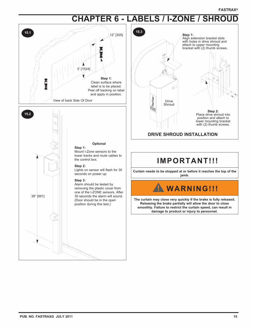
CHAPTER 6 - LABELS / I-ZONE / SHROUD
The curtain may close very quickly if the brake is fully released.
Releasing the brake partially will allow the door to close
smoothly. Failure to restrict the curtain speed, can result in
damage to product or injury to personnel.
WARNING!!!!
DRIVE SHROUD INSTALLATION
DriveShroud
15.3
View of back Side Of Door
12” [305]
5’ [1524]
15.1
39” [991]
15.2
Curtain needs to be stopped at or before it reaches the top of the
jamb.
IMPORTANT!!!
Optional
Step 1:
Mount I-Zone sensors to the
lower tracks and route cables to
the control box.
Step 2:
Lights on sensor will flash for 30
seconds on power up.
Step 3:
Alarm should be tested by
removing the plastic cover from
one of the I-ZONE sensors. After
30 seconds the alarm will sound.
(Door should be in the open
position during this test.)
Step 1:
Clean surface where
label is to be placed.
Peel off backing on label
and apply in position.
Step 2:Place drive shroud intoposition and attach to
lower mounting bracketwith (2) thumb screws.
Step 1:Align extension bracket slotswith holes in drive shroud andattach to upper mountingbracket with (2) thumb screws.
16 PUB. NO. FASTRAXG JULY 2011
FASTRAX®
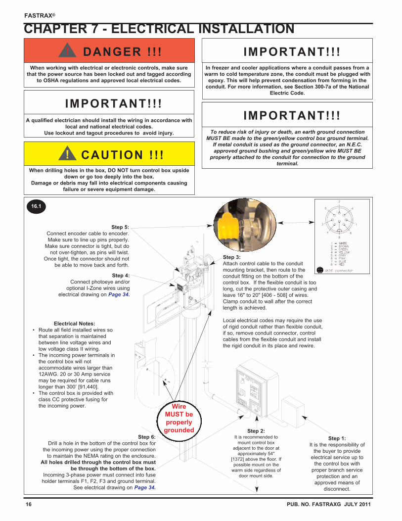
CHAPTER 7 - ELECTRICAL INSTALLATION
A qualified electrician should install the wiring in accordance with
local and national electrical codes.
Use lockout and tagout procedures to avoid injury.
IMPORTANT!!!
When drilling holes in the box, DO NOT turn control box upside
down or go too deeply into the box.
Damage or debris may fall into electrical components causing
failure or severe equipment damage.
CAUTION ! ! !!
To reduce risk of injury or death, an earth ground connectionMUST BE made to the green/yellow control box ground terminal.
If metal conduit is used as the ground connector, an N.E.C.approved ground bushing and green/yellow wire MUST BE
properly attached to the conduit for connection to the groundterminal.
IMPORTANT!!!
In freezer and cooler applications where a conduit passes from a
warm to cold temperature zone, the conduit must be plugged with
epoxy. This will help prevent condensation from forming in the
conduit. For more information, see Section 300-7a of the National
Electric Code.
IMPORTANT!!!
Electrical Notes:
• Route all field installed wires so
that separation is maintained
between line voltage wires and
low voltage class II wiring.
• The incoming power terminals in
the control box will not
accommodate wires larger than
12AWG. 20 or 30 Amp service
may be required for cable runs
longer than 300’ [91,440].
• The control box is provided with
class CC protective fusing for
the incoming power. Wire
MUST be
properly
grounded
16.1
When working with electrical or electronic controls, make sure
that the power source has been locked out and tagged according
to OSHA regulations and approved local electrical codes.
DANGER !! !!
Step 3:
Attach control cable to the conduit
mounting bracket, then route to the
conduit fitting on the bottom of the
control box. If the flexible conduit is too
long, cut the protective outer casing and
leave 16" to 20" [406 - 508] of wires.
Clamp conduit to wall after the correct
length is achieved.
Local electrical codes may require the use
of rigid conduit rather than flexible conduit,
if so, remove conduit connector, control
cables from the flexible conduit and install
the rigid conduit in its place and rewire.
Step 2:It is recommended to
mount control box
adjacent to the door at
approximately 54"
[1372] above the floor. If
possible mount on the
warm side regardless of
door mount side.
Step 1:
It is the responsibility of
the buyer to provide
electrical service up to
the control box with
proper branch service
protection and an
approved means of
disconnect.
Step 6:
Drill a hole in the bottom of the control box for
the incoming power using the proper connection
to maintain the NEMA rating on the enclosure.
All holes drilled through the control box must
be through the bottom of the box.
Incoming 3-phase power must connect into fuse
holder terminals F1, F2, F3 and ground terminal.
See electrical drawing on Page 34.
Step 4:
Connect photoeye and/or
optional I-Zone wires using
electrical drawing on Page 34.
Step 5:
Connect encoder cable to encoder.
Make sure to line up pins properly.
Make sure connector is tight, but do
not over-tighten, as pins will twist.
Once tight, the connector should not
be able to move back and forth.
PUB. NO. FASTRAXG JULY 2011 17
FASTRAX®
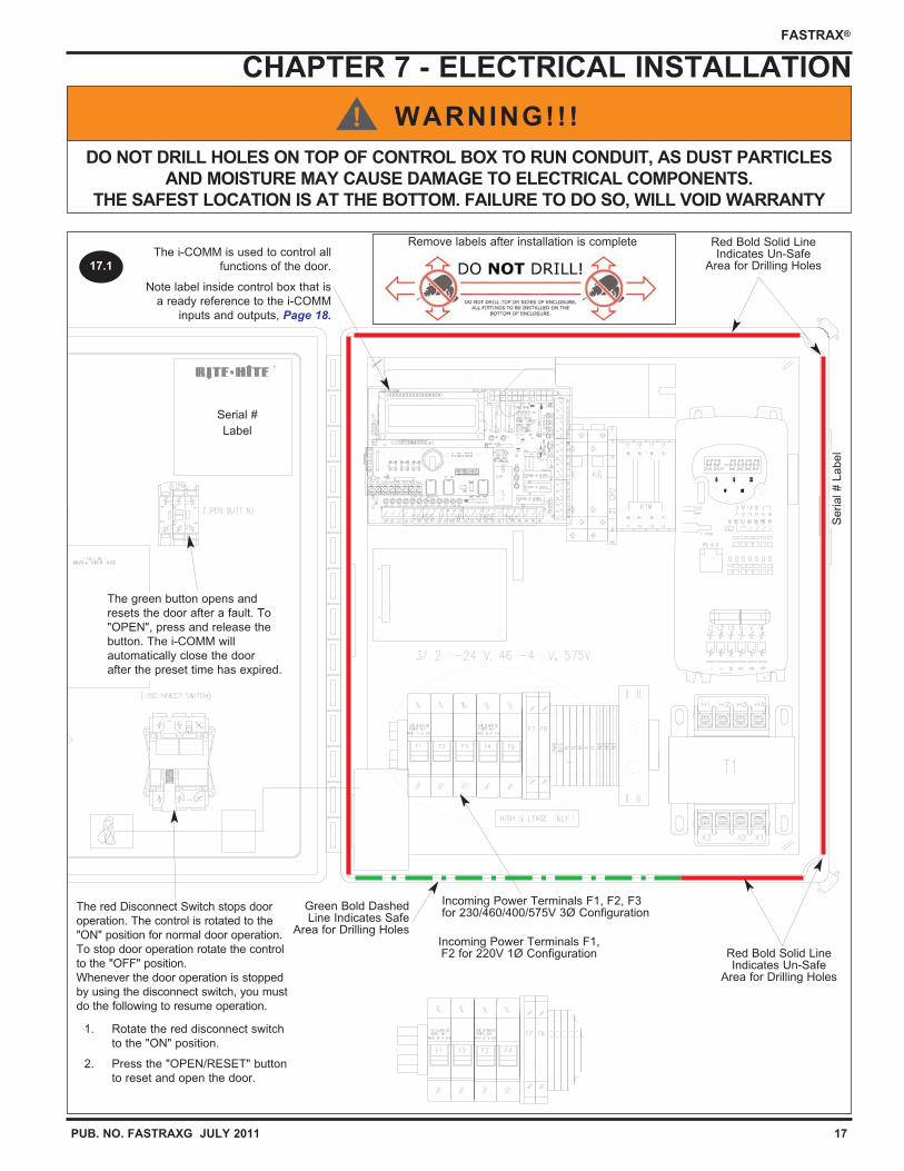
CHAPTER 7 - ELECTRICAL INSTALLATION
DO NOT DRILL HOLES ON TOP OF CONTROL BOX TO RUN CONDUIT, AS DUST PARTICLES
AND MOISTURE MAY CAUSE DAMAGE TO ELECTRICAL COMPONENTS.
THE SAFEST LOCATION IS AT THE BOTTOM. FAILURE TO DO SO, WILL VOID WARRANTY
WARNING!!!!
Incoming Power Terminals F1, F2, F3for 230/460/400/575V 3Ø Configuration
Incoming Power Terminals F1,F2 for 220V 1Ø Configuration
Serial # L
abel
Serial #
Label
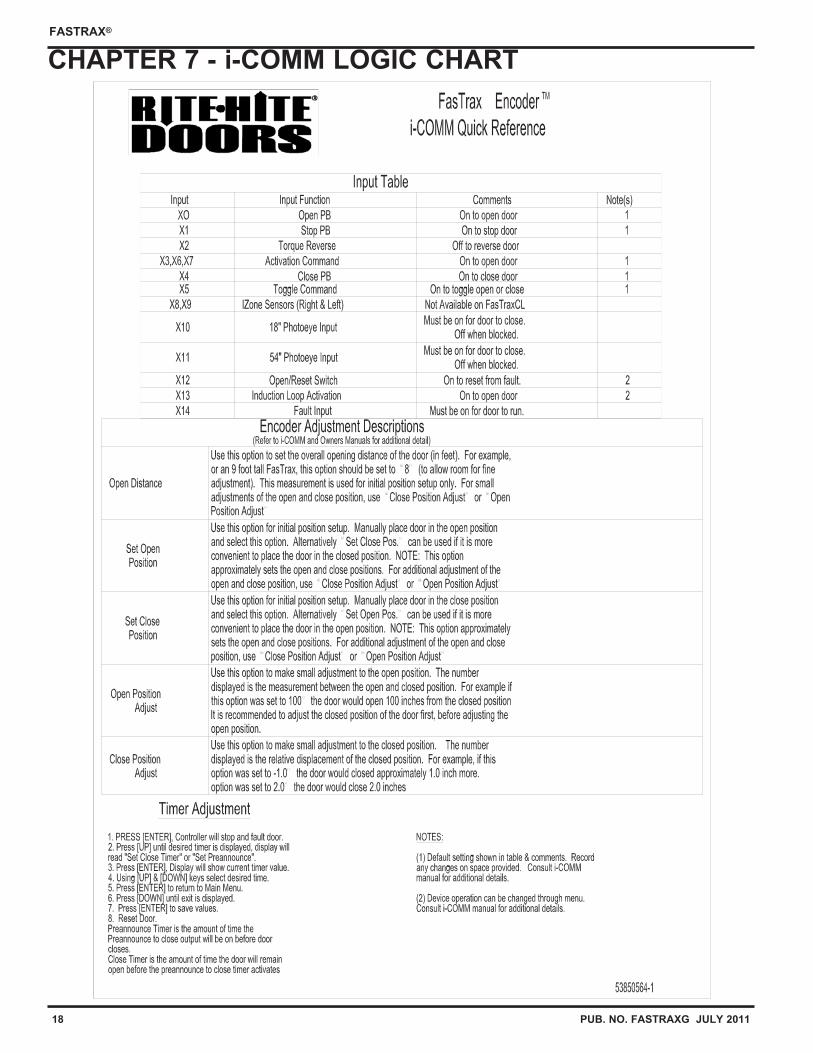
The i-COMM is used to control all
functions of the door.
Note label inside control box that is
a ready reference to the i-COMM
inputs and outputs, Page 18.
Green Bold DashedLine Indicates Safe
Area for Drilling Holes
Red Bold Solid LineIndicates Un-Safe
Area for Drilling Holes
Red Bold Solid LineIndicates Un-Safe
Area for Drilling Holes
The green button opens and
resets the door after a fault. To
"OPEN", press and release the
button. The i-COMM will
automatically close the door
after the preset time has expired.
The red Disconnect Switch stops door
operation. The control is rotated to the
"ON" position for normal door operation.
To stop door operation rotate the control
to the "OFF" position.
Whenever the door operation is stopped
by using the disconnect switch, you must
do the following to resume operation.
1. Rotate the red disconnect switch
to the "ON" position.
2. Press the "OPEN/RESET" button
to reset and open the door.
Remove labels after installation is complete
17.1
18 PUB. NO. FASTRAXG JULY 2011
FASTRAX®
CHAPTER 7 - i-COMM LOGIC CHART
PUB. NO. FASTRAXG JULY 2011 19
FASTRAX®
CHAPTER 7 - ENCODER SETUPENCODER SETUP INSTRUCTIONS
1. Verify wiring to encoder is properly terminated.
Note: right-hand drive doors require a wire to beterminated in the ‘DC’ terminal, while left-hand drive doorsdo not. If motor phase is changed during this setup,please restart this procedure.
2. Move curtain to closed position.
3. Power up door and press enter button to enter “MAIN MENU”.
4. Using down arrow, scroll to “Open Distance”.
5. Press enter button to view parameter value (measured infeet), should be O.D.H. - (two) 2’. Change the value usingthe up or down arrow keys, round down if required, thenpress enter to return to “MAIN MENU”.
6. Scroll using down arrow to item “Set Close Pos.”.
7. Press enter button to view parameter. The controller willdisplay the following message “RESET ALL LIMITS” …“Press Up to Start”. Pressing the up arrow key will resetall of the limits, and reboot the controller.
NOTE: DO NOT use this menu item to makeadjustment to the limits; this is only for initial setup.
8. Press green Open/Reset button.
a. The door should begin to open, be ready to shutdownthe door if it begins to move in the wrong direction. Ifmotor phase is changed, start over at step #2.
b. If rotation is correct proceed to the instructions foradjusting the “Open and Close positions”.
Open and Close Position Adjustment
To adjust CLOSE position:
1. Power up door and press enter button to enter “MAINMENU”.
2. Scroll using up arrow to the item “Close Pos. Adjust”.
3. Press enter button to view parameter value. Thisparameter will show a coded value on the left and relativechange in inches on the right. When entering thisparameter the value will always start at 0.0”.
Change values using the up or down arrows.
To bring the curtain closer to the floor, adjust this value sothat it is less than zero. (i.e. To close the door 4” more,the value for “Close Pos. Adjust” will be -4.0”) Movingthis parameter in the positive direction raises the curtainrelative to the floor. Changing this value will not affect theopen position.
Note: If you leave this parameter and return to it, its value willagain be zero. Any changes made before leaving theparameter will still be effective. For example: If youlowered the door 4.0”, leave the parameter and return, theparameter will display 0.0”. Even though the displayshows 0.0” the -4.0” change has been recorded.
4. When parameter is changed press enter button for three(3) seconds to return to the “MAIN MENU”.
5. Test operation of door and continue adjustment.
TIP: At any point in the menu mode, Pressing and holding theenter button for at least 2 seconds will cause thecontroller to automatically accept all the changes madeand exit the menu system.
To adjust the OPEN position:
1. Power up door and press enter button to enter “MAIN MENU”.
2. Using up arrow key, scroll to “Open Pos. Adjust”.
3. Press enter button to view parameter value. Thisparameter will show a coded value on the left and theopening height in inches on the right. This value willalways be less than the door opening height.
Change the value using the up and down arrow keys.
To bring the open position down (closer to the floor)adjust this value to be less than the current value. Toopen the door more relative to the floor, adjust thisparameter in a positive direction. (i.e. To open the door 4”more, and the current value is 72.0”. Change the valuefor “Open Pos. Adjust” to be 76.0”). Changing this valuewill not affect the close position.
4. When parameter is changed press enter button for three(3) seconds to return to the “MAIN MENU”.
5. Test operation of the door, and continue adjustment.
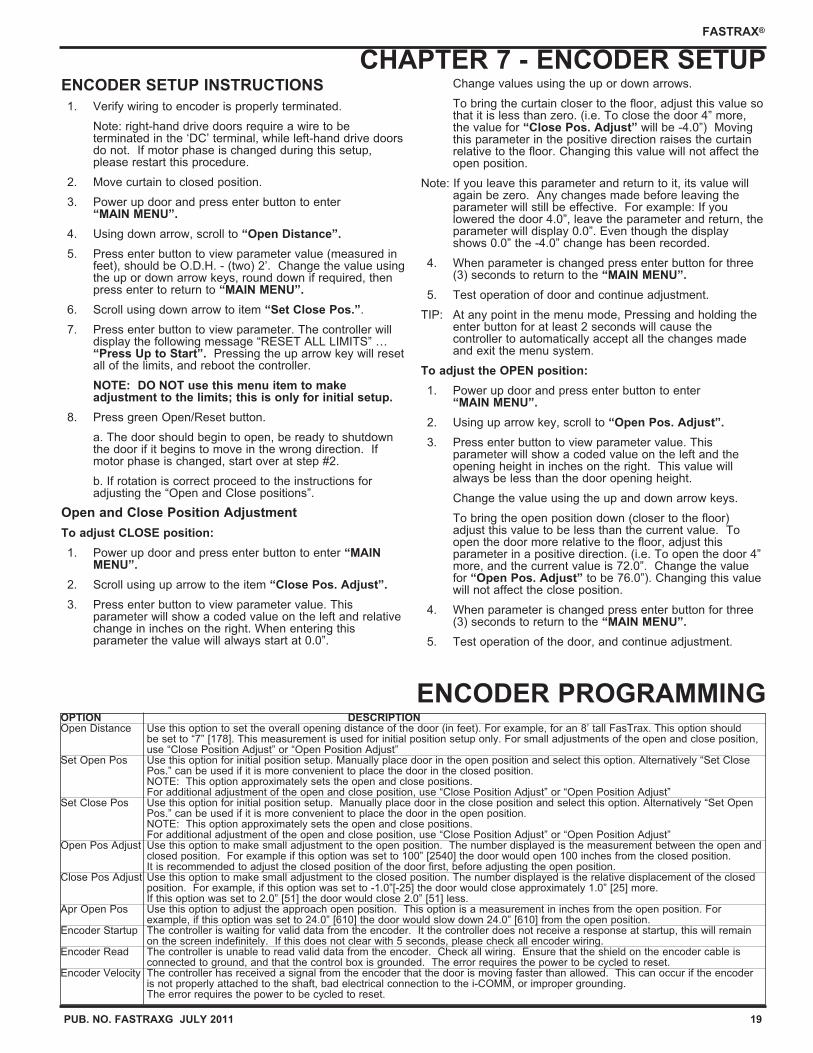
ENCODER PROGRAMMINGOPTION DESCRIPTIONOpen Distance Use this option to set the overall opening distance of the door (in feet). For example, for an 8’ tall FasTrax. This option should
be set to “7” [178]. This measurement is used for initial position setup only. For small adjustments of the open and close position, use “Close Position Adjust” or “Open Position Adjust”
Set Open Pos Use this option for initial position setup. Manually place door in the open position and select this option. Alternatively “Set Close Pos.” can be used if it is more convenient to place the door in the closed position.NOTE: This option approximately sets the open and close positions.For additional adjustment of the open and close position, use “Close Position Adjust” or “Open Position Adjust”
Set Close Pos Use this option for initial position setup. Manually place door in the close position and select this option. Alternatively “Set Open Pos.” can be used if it is more convenient to place the door in the open position.NOTE: This option approximately sets the open and close positions.For additional adjustment of the open and close position, use “Close Position Adjust” or “Open Position Adjust”
Open Pos Adjust Use this option to make small adjustment to the open position. The number displayed is the measurement between the open and closed position. For example if this option was set to 100” [2540] the door would open 100 inches from the closed position. It is recommended to adjust the closed position of the door first, before adjusting the open position.
Close Pos Adjust Use this option to make small adjustment to the closed position. The number displayed is the relative displacement of the closed position. For example, if this option was set to -1.0”[-25] the door would close approximately 1.0” [25] more. If this option was set to 2.0” [51] the door would close 2.0” [51] less.
Apr Open Pos Use this option to adjust the approach open position. This option is a measurement in inches from the open position. For example, if this option was set to 24.0” [610] the door would slow down 24.0” [610] from the open position.
Encoder Startup The controller is waiting for valid data from the encoder. It the controller does not receive a response at startup, this will remain on the screen indefinitely. If this does not clear with 5 seconds, please check all encoder wiring.
Encoder Read The controller is unable to read valid data from the encoder. Check all wiring. Ensure that the shield on the encoder cable is connected to ground, and that the control box is grounded. The error requires the power to be cycled to reset.
Encoder Velocity The controller has received a signal from the encoder that the door is moving faster than allowed. This can occur if the encoder is not properly attached to the shaft, bad electrical connection to the i-COMM, or improper grounding. The error requires the power to be cycled to reset.
20 PUB. NO. FASTRAXG JULY 2011
FASTRAX®
VERIFY DOOR OPERATION / CHECKLIST
1. It is recommended that the operation of all controls on the
FasTrax be verified monthly.
2. The door operations are controlled by a Universal
Controller. The controller is set-up and programmed
during testing at the factory. Unless you are a
RITE-HITE DOORS, INC. authorized service technician,
you should not attempt to change the program.
3. A quick way of determining that the door is ready to
operate, is to open the control box and look at the row of
(X) green Input LED’s on the i-COMM and the label to
verify proper state.
4. Are door opening dimensions correct ?
5. Tracks shimmed as required?
6. Tracks aligned when installing wall fasteners ?
7. Are the pillow block bearing set screws tightened to 66 to
80 in.-lb. ?
8. Check for proper line voltage ?
9. Are all mounting bolts tight ?
10. All wires connected for the photoeyes ?
11. Are loose wires secured away from moving parts?
12. With the power on, press the "OPEN" button, the door
should open and close automatically after a short delay.
To adjust the amount of door open time, the setting must
be changed in the i-COMM controller.
13. Operate and observe the door opening to make sure that
it fully opens. Observe the closing action to make sure
that the door operates smoothly, and fully closes without
excessive curtain ripple.
If it is necessary to adjust either position, refer to Encoder
adjustment section.
14. While the door is closing, block the reversing photoeyes.
The door should reverse direction and move to the open
position, and then continue to operate.
15. Using end user material handling equipment, approach
door slowly and verify that all the activation devices that
are being used are operating properly. DO NOT attempt to
drive through a door in which the green button is flashing.
16. Use caution (honk horn) and look in all directions when
approaching a door that is closing and ensure that the
door will reverse before proceeding.
17. Pedestrians should be advised to use man doors when
present and to not lean into the door way.
18. A fault will occur if the optional non-powered chain hoist
chain is pulled, simply press the green flashing
"OPEN/RESET" button to return to normal operation.
19. Motor shroud installed.
20. Ground and Shield wires have been properly
terminated.
CHAPTER 8 - DOOR OPERATION / FINAL CHECKLIST
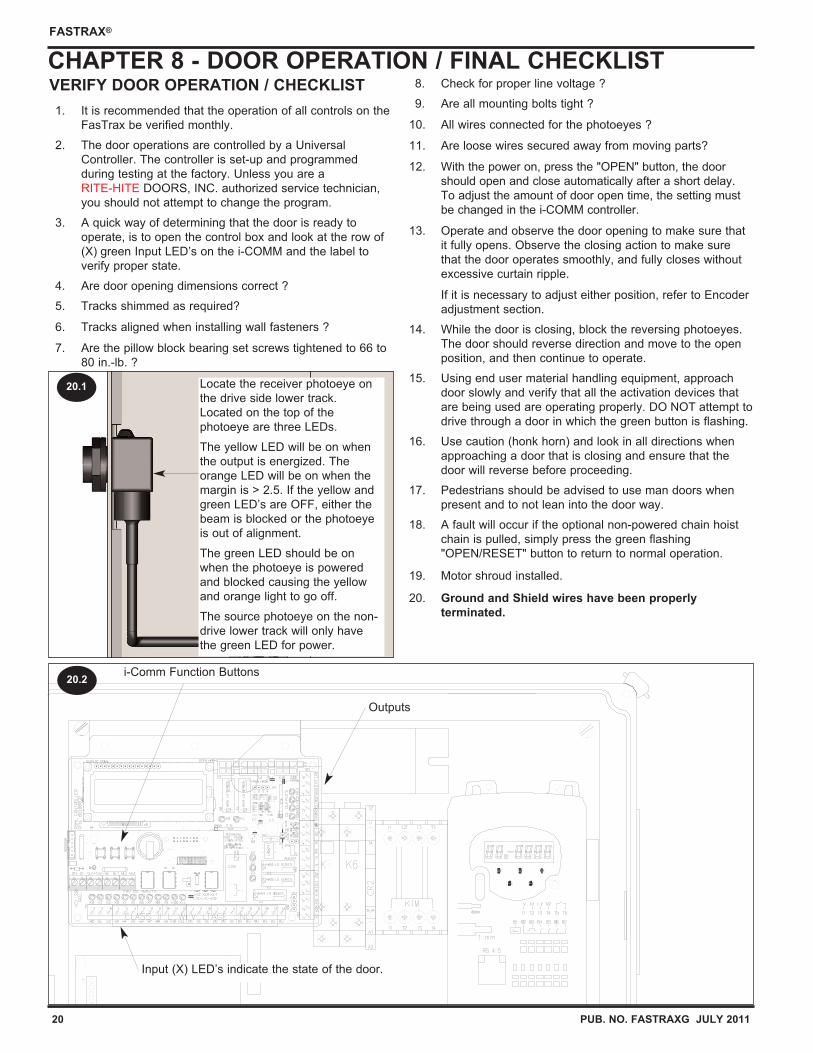
Locate the receiver photoeye on
the drive side lower track.
Located on the top of the
photoeye are three LEDs.
The yellow LED will be on when
the output is energized. The
orange LED will be on when the
margin is > 2.5. If the yellow and
green LED’s are OFF, either the
beam is blocked or the photoeye
is out of alignment.
The green LED should be on
when the photoeye is powered
and blocked causing the yellow
and orange light to go off.
The source photoeye on the non-
drive lower track will only have
the green LED for power.
20.1
i-Comm Function Buttons
Input (X) LED’s indicate the state of the door.
Outputs
20.2
PUB. NO. FASTRAXG JULY 2011 21
FASTRAX®
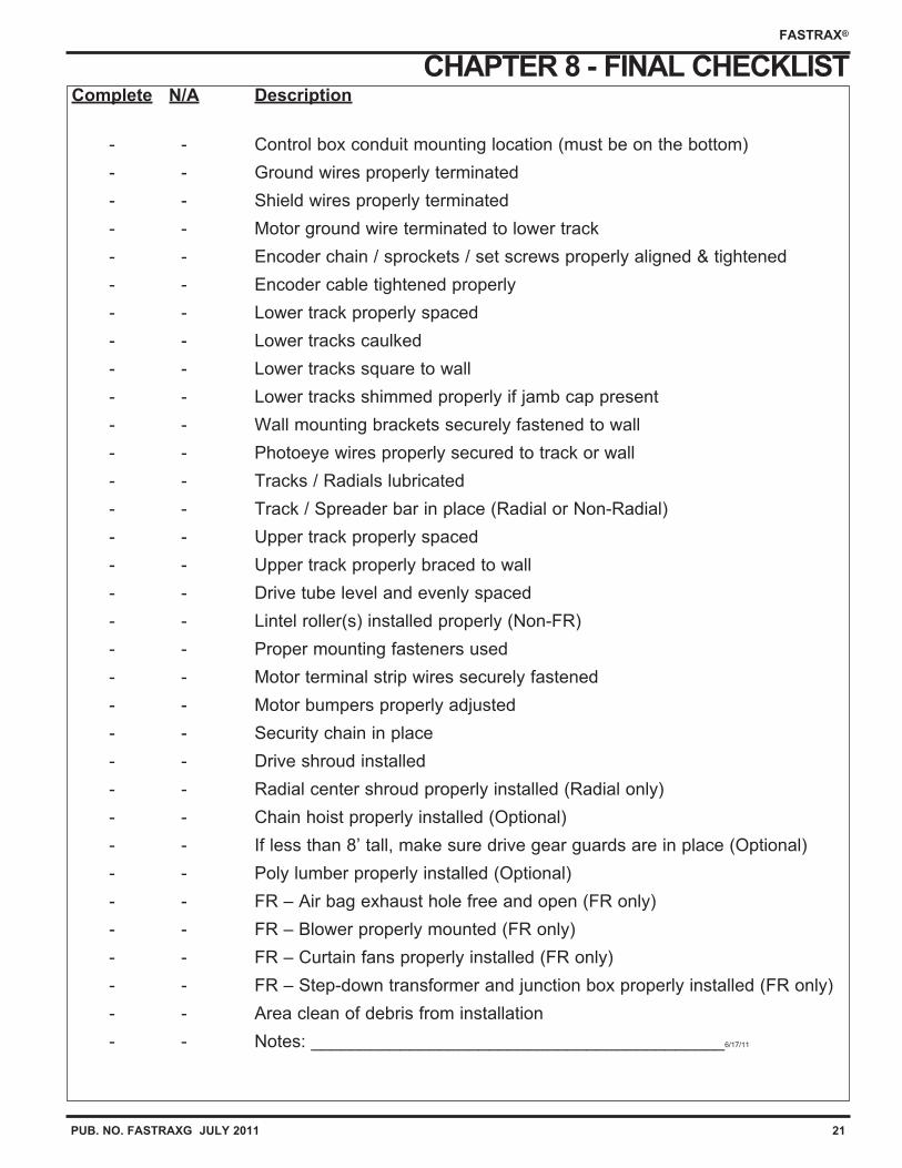
CHAPTER 8 - FINAL CHECKLISTComplete N/A Description
- - Control box conduit mounting location (must be on the bottom)
- - Ground wires properly terminated
- - Shield wires properly terminated
- - Motor ground wire terminated to lower track
- - Encoder chain / sprockets / set screws properly aligned & tightened
- - Encoder cable tightened properly
- - Lower track properly spaced
- - Lower tracks caulked
- - Lower tracks square to wall
- - Lower tracks shimmed properly if jamb cap present
- - Wall mounting brackets securely fastened to wall
- - Photoeye wires properly secured to track or wall
- - Tracks / Radials lubricated
- - Track / Spreader bar in place (Radial or Non-Radial)
- - Upper track properly spaced
- - Upper track properly braced to wall
- - Drive tube level and evenly spaced
- - Lintel roller(s) installed properly (Non-FR)
- - Proper mounting fasteners used
- - Motor terminal strip wires securely fastened
- - Motor bumpers properly adjusted
- - Security chain in place
- - Drive shroud installed
- - Radial center shroud properly installed (Radial only)
- - Chain hoist properly installed (Optional)
- - If less than 8’ tall, make sure drive gear guards are in place (Optional)
- - Poly lumber properly installed (Optional)
- - FR – Air bag exhaust hole free and open (FR only)
- - FR – Blower properly mounted (FR only)
- - FR – Curtain fans properly installed (FR only)
- - FR – Step-down transformer and junction box properly installed (FR only)
- - Area clean of debris from installation
- - Notes: __________________________________________6/17/11
22 PUB. NO. FASTRAXG JULY 2011
FASTRAX®
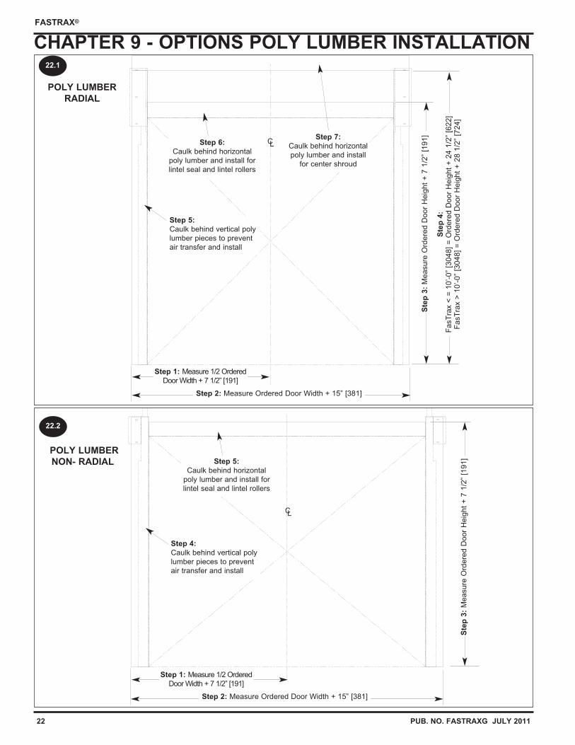
CHAPTER 9 - OPTIONS POLY LUMBER INSTALLATION
POLY LUMBER
NON- RADIALS
tep
3:
Measure
Ord
ere
d D
oor
Heig
ht
+ 7
1/2
” [1
91]
CL
22.2
POLY LUMBER
RADIAL
Ste
p 4
:F
asT
rax <
= 1
0’-0”
[3048]
= O
rdere
d D
oor
Heig
ht
+ 2
4 1
/2”
[622]
FasT
rax >
10’-0”
[30
48]
= O
rdere
d D
oor
Heig
ht
+ 2
8 1
/2”
[724]
CL
Step 2: Measure Ordered Door Width + 15” [381]
Step 1: Measure 1/2 Ordered
Door Width + 7 1/2” [191]
Ste
p 3
:M
easure
Ord
ere
d D
oor
Heig
ht
+ 7
1/2
” [1
91]
22.1
Step 5:
Caulk behind vertical poly
lumber pieces to prevent
air transfer and install
Step 6:
Caulk behind horizontal
poly lumber and install for
lintel seal and lintel rollers
Step 7:
Caulk behind horizontal
poly lumber and install
for center shroud
Step 4:
Caulk behind vertical poly
lumber pieces to prevent
air transfer and install
Step 2: Measure Ordered Door Width + 15” [381]
Step 1: Measure 1/2 Ordered
Door Width + 7 1/2” [191]
Step 5:
Caulk behind horizontal
poly lumber and install for
lintel seal and lintel rollers
PUB. NO. FASTRAXG JULY 2011 23
FASTRAX®
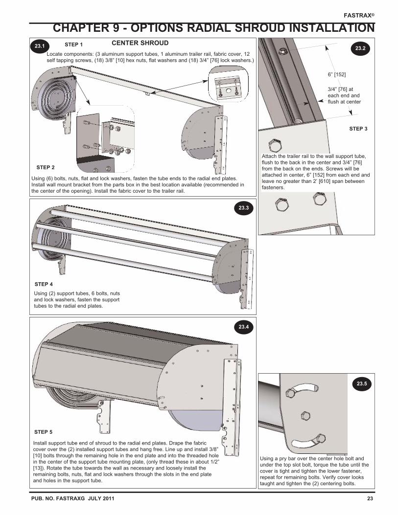
CHAPTER 9 - OPTIONS RADIAL SHROUD INSTALLATIONCENTER SHROUD
Locate components: (3 aluminum support tubes, 1 aluminum trailer rail, fabric cover, 12
self tapping screws, (18) 3/8” [10] hex nuts, flat washers and (18) 3/4” [76] lock washers.)
STEP 3
STEP 2
STEP 4
STEP 5
Install support tube end of shroud to the radial end plates. Drape the fabric
cover over the (2) installed support tubes and hang free. Line up and install 3/8”
[10] bolts through the remaining hole in the end plate and into the threaded hole
in the center of the support tube mounting plate, (only thread these in about 1/2”
[13]). Rotate the tube towards the wall as necessary and loosely install the
remaining bolts, nuts, flat and lock washers through the slots in the end plate
and holes in the support tube.
23.1
Using (6) bolts, nuts, flat and lock washers, fasten the tube ends to the radial end plates.
Install wall mount bracket from the parts box in the best location available (recommended in
the center of the opening). Install the fabric cover to the trailer rail.
Using (2) support tubes, 6 bolts, nuts
and lock washers, fasten the support
tubes to the radial end plates.
Attach the trailer rail to the wall support tube,
flush to the back in the center and 3/4” [76]
from the back on the ends. Screws will be
attached in center, 6” [152] from each end and
leave no greater than 2’ [610] span between
fasteners.
Using a pry bar over the center hole bolt and
under the top slot bolt, torque the tube until the
cover is tight and tighten the lower fastener,
repeat for remaining bolts. Verify cover looks
taught and tighten the (2) centering bolts.
6” [152]
3/4” [76] at
each end and
flush at center
STEP 123.2
23.3
23.4
23.5
24 PUB. NO. FASTRAXG JULY 2011
FASTRAX®
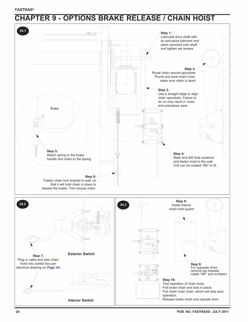
CHAPTER 9 - OPTIONS BRAKE RELEASE / CHAIN HOIST
Brake
Interior Switch
Exterior Switch
24.1
24.324.2
Step 6:
Fasten chain lock bracket to wall, so
that it will hold chain in place to
release the brake. Trim excess chain.
Step 5:
Attach spring to the brake
handle and chain to the spring.
Step 4:
Mark and drill hole locations
and fasten hoist to the wall.
Unit can be rotated 180° to fit.
Step 3:
Use a straight edge to align
chain sprockets. Failure to
do so may result in noise
and premature wear.
Step 2:
Route chain around sprockets
Plumb and level chain hoist,
make sure chain is taunt
Step 1:
Lubricate drive shaft with
an anti-seize lubricant and
place sprocket onto shaft
and tighten set screws
Step 10:
Test operation of chain hoist.
Pull brake chain and lock in place.
Pull chain hoist chain, which will stop door
operation.
Release brake chain and operate door.
Step 7:
Plug in cable and wire chain
hoist into control box per
electrical drawing on Page 34.
Step 8:
Install interior
chain hoist guard
Step 9:For opposite drive,remove top bracket,rotate 180° and re-fasten
PUB. NO. FASTRAXG JULY 2011 25
FASTRAX®
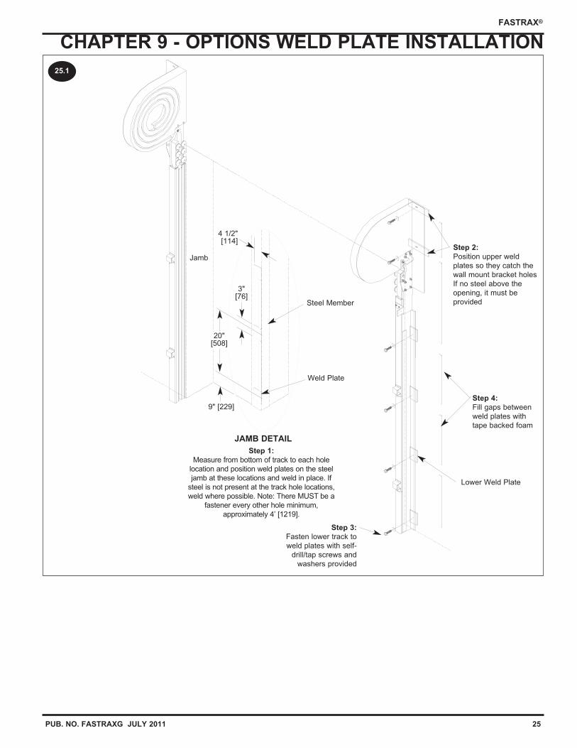
CHAPTER 9 - OPTIONS WELD PLATE INSTALLATION
Lower Weld Plate
Jamb
Steel Member
Weld Plate
JAMB DETAIL
4 1/2"[114]
3"[76]
20"[508]
9" [229]
25.1
Step 3:
Fasten lower track to
weld plates with self-
drill/tap screws and
washers provided
Step 2:
Position upper weld
plates so they catch the
wall mount bracket holes
If no steel above the
opening, it must be
provided
Step 1:
Measure from bottom of track to each hole
location and position weld plates on the steel
jamb at these locations and weld in place. If
steel is not present at the track hole locations,
weld where possible. Note: There MUST be a
fastener every other hole minimum,
approximately 4’ [1219].
Step 4:
Fill gaps between
weld plates with
tape backed foam
26 PUB. NO. FASTRAXG JULY 2011
FASTRAX®
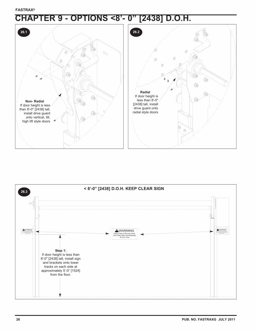
CHAPTER 9 - OPTIONS <8’- 0” [2438] D.O.H.
Non- Radial
If door height is less
than 8'-0" [2438] tall,
install drive guard
onto vertical, tilt,
high lift style doors
Radial
If door height is
less than 8'-0"
[2438] tall, install
drive guard onto
radial style doors
WARNINGKeep Clear of Moving Parts.
Door May Start Automatically
At Any Time.
WARNINGKeep Clear of Moving Parts.
Door May Start Automatically
At Any Time.
WARNINGKeep Clear of Moving Parts.
Door May Start Automatically
At Any Time.
< 8’-0” [2438] D.O.H. KEEP CLEAR SIGN
26.1 26.2
26.3
Step 1:
If door height is less than
8'-0" [2438] tall, install sign
and brackets onto lower
tracks on each side at
approximately 5’-0” [1524]
from the floor.
PUB. NO. FASTRAXG JULY 2011 27
FASTRAX®
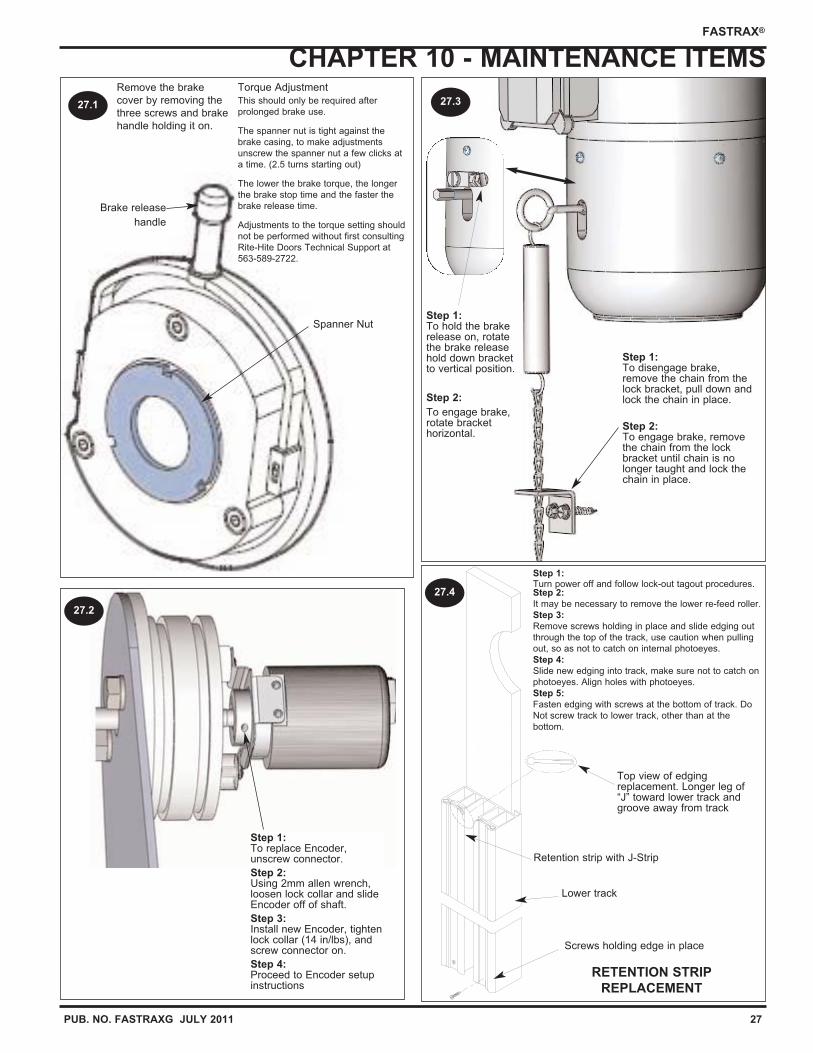
CHAPTER 10 - MAINTENANCE ITEMS
RETENTION STRIP
REPLACEMENT
Screws holding edge in place
Lower track
Retention strip with J-Strip
Brake release
handle
Torque Adjustment
This should only be required after
prolonged brake use.
The spanner nut is tight against the
brake casing, to make adjustments
unscrew the spanner nut a few clicks at
a time. (2.5 turns starting out)
The lower the brake torque, the longer
the brake stop time and the faster the
brake release time.
Adjustments to the torque setting should
not be performed without first consulting
Rite-Hite Doors Technical Support at
563-589-2722.
Remove the brake
cover by removing the
three screws and brake
handle holding it on.
Top view of edgingreplacement. Longer leg of“J” toward lower track andgroove away from track
Spanner Nut
27.1 27.3
27.4
Step 1:To disengage brake,remove the chain from thelock bracket, pull down andlock the chain in place.
Step 2:To engage brake, removethe chain from the lockbracket until chain is nolonger taught and lock thechain in place.
Step 1:Turn power off and follow lock-out tagout procedures.Step 2:
It may be necessary to remove the lower re-feed roller.
Step 3:
Remove screws holding in place and slide edging out
through the top of the track, use caution when pulling
out, so as not to catch on internal photoeyes.
Step 4:
Slide new edging into track, make sure not to catch on
photoeyes. Align holes with photoeyes.
Step 5:
Fasten edging with screws at the bottom of track. Do
Not screw track to lower track, other than at the
bottom.
Step 1:To replace Encoder,unscrew connector.
Step 2:Using 2mm allen wrench,loosen lock collar and slideEncoder off of shaft.
Step 3:Install new Encoder, tightenlock collar (14 in/lbs), andscrew connector on.
Step 4:Proceed to Encoder setupinstructions
27.2
Step 1:To hold the brakerelease on, rotatethe brake releasehold down bracketto vertical position.
Step 2:
To engage brake,rotate brackethorizontal.
28 PUB. NO. FASTRAXG JULY 2011
FASTRAX®
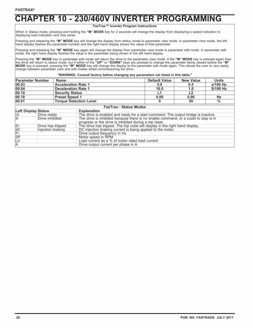
CHAPTER 10 - 230/460V INVERTER PROGRAMMINGFasTrax™ Inverter Program Instructions
When in Status mode, pressing and holding the “M” MODE key for 2 seconds will change the display from displaying a speed indication todisplaying load indication and visa versa.
Pressing and releasing the “M” MODE key will change the display from status mode to parameter view mode. In parameter view mode, the lefthand display flashes the parameter number and the right hand display shows the value of that parameter.
Pressing and releasing the “M” MODE key again will change the display from parameter view mode to parameter edit mode. In parameter editmode, the right hand display flashes the value in the parameter being shown in the left hand display.
Pressing the “M” MODE key in parameter edit mode will return the drive to the parameter view mode. If the “M” MODE key is pressed again thenthe drive will return to status mode, but if either of the “UP” or “DOWN” keys are pressed to change the parameter being viewed before the “M”MODE key is pressed, pressing the “M” MODE key will change the display to the parameter edit mode again. This allows the user to very easilychange between parameter view and edit modes whilst commissioning the drive.
"WARNING: Consult factory before changing any parameters not listed in this table."
Parameter Number Name Default Value New Value Units00.03 Acceleration Rate 1 5.0 0.5 s/100 Hz00.04 Deceleration Rate 1 10.0 1.0 S/100 Hz00.10 Security Status L1 L200.18 Preset Speed 1 0.00 0.00 Hz00.61 Torque Detection Level 0 50 %
FasTrax - Status Modes Left Display Status Explanationrd Drive ready The drive is enabled and ready for a start command. The output bridge is inactive.ih Drive inhibited The drive is inhibited because there is no enable command, or a coast to stop is in
progress or the drive is inhibited during a trip reset.Er Drive has tripped The drive has tripped. The trip code will display in the right hand display.dC Injection braking DC injection braking current is being applied to the motor.Fr Drive output frequency in HzSP Motor speed in RPMLd Load current as a % of motor rated load currentA Drive output current per phase in A
PUB. NO. FASTRAXG JULY 2011 29
FASTRAX®
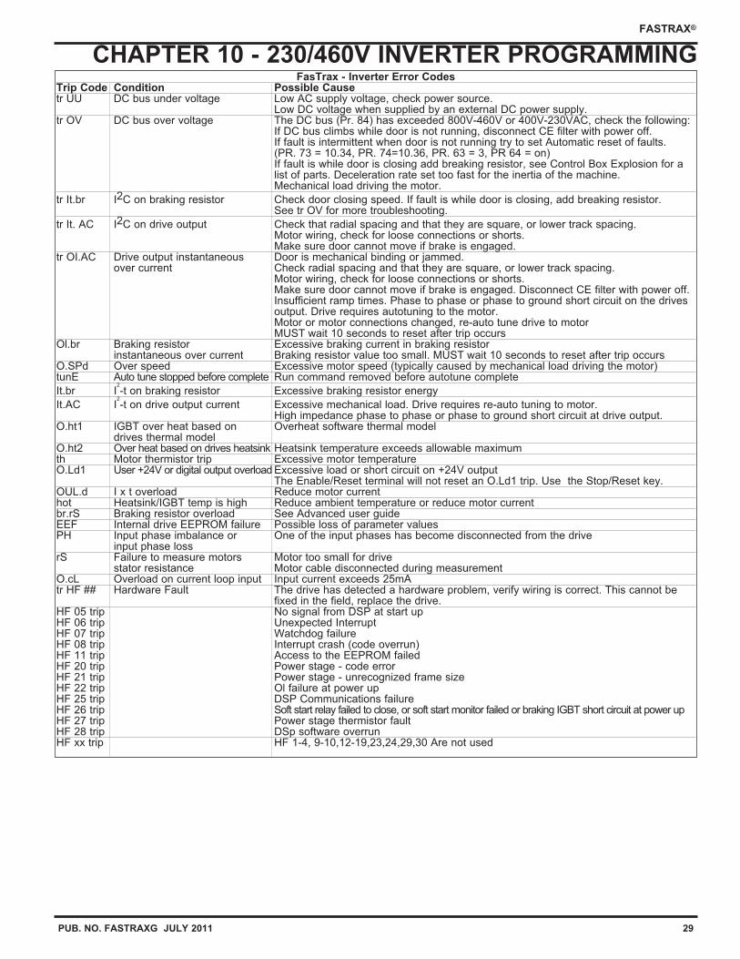
CHAPTER 10 - 230/460V INVERTER PROGRAMMINGFasTrax - Inverter Error Codes
Trip Code Condition Possible Causetr UU DC bus under voltage Low AC supply voltage, check power source.
Low DC voltage when supplied by an external DC power supply.tr OV DC bus over voltage The DC bus (Pr. 84) has exceeded 800V-460V or 400V-230VAC, check the following:
If DC bus climbs while door is not running, disconnect CE filter with power off.If fault is intermittent when door is not running try to set Automatic reset of faults. (PR. 73 = 10.34, PR. 74=10.36, PR. 63 = 3, PR 64 = on)If fault is while door is closing add breaking resistor, see Control Box Explosion for a list of parts. Deceleration rate set too fast for the inertia of the machine.Mechanical load driving the motor.
tr It.br I2C on braking resistor Check door closing speed. If fault is while door is closing, add breaking resistor.See tr OV for more troubleshooting.
tr It. AC I2C on drive output Check that radial spacing and that they are square, or lower track spacing.Motor wiring, check for loose connections or shorts.Make sure door cannot move if brake is engaged.
tr OI.AC Drive output instantaneous Door is mechanical binding or jammed.over current Check radial spacing and that they are square, or lower track spacing.
Motor wiring, check for loose connections or shorts.Make sure door cannot move if brake is engaged. Disconnect CE filter with power off.Insufficient ramp times. Phase to phase or phase to ground short circuit on the drives output. Drive requires autotuning to the motor.Motor or motor connections changed, re-auto tune drive to motorMUST wait 10 seconds to reset after trip occurs
Ol.br Braking resistor Excessive braking current in braking resistorinstantaneous over current Braking resistor value too small. MUST wait 10 seconds to reset after trip occurs
O.SPd Over speed Excessive motor speed (typically caused by mechanical load driving the motor)tunE Auto tune stopped before complete Run command removed before autotune complete
It.br I2
-t on braking resistor Excessive braking resistor energy
It.AC I2
-t on drive output current Excessive mechanical load. Drive requires re-auto tuning to motor.High impedance phase to phase or phase to ground short circuit at drive output.
O.ht1 IGBT over heat based on Overheat software thermal modeldrives thermal model
O.ht2 Over heat based on drives heatsink Heatsink temperature exceeds allowable maximumth Motor thermistor trip Excessive motor temperatureO.Ld1 User +24V or digital output overload Excessive load or short circuit on +24V output
The Enable/Reset terminal will not reset an O.Ld1 trip. Use the Stop/Reset key.OUL.d I x t overload Reduce motor currenthot Heatsink/IGBT temp is high Reduce ambient temperature or reduce motor currentbr.rS Braking resistor overload See Advanced user guideEEF Internal drive EEPROM failure Possible loss of parameter valuesPH Input phase imbalance or One of the input phases has become disconnected from the drive
input phase lossrS Failure to measure motors Motor too small for drive
stator resistance Motor cable disconnected during measurementO.cL Overload on current loop input Input current exceeds 25mAtr HF ## Hardware Fault The drive has detected a hardware problem, verify wiring is correct. This cannot be
fixed in the field, replace the drive.HF 05 trip No signal from DSP at start upHF 06 trip Unexpected InterruptHF 07 trip Watchdog failureHF 08 trip Interrupt crash (code overrun)HF 11 trip Access to the EEPROM failedHF 20 trip Power stage - code errorHF 21 trip Power stage - unrecognized frame sizeHF 22 trip Ol failure at power upHF 25 trip DSP Communications failureHF 26 trip Soft start relay failed to close, or soft start monitor failed or braking IGBT short circuit at power upHF 27 trip Power stage thermistor faultHF 28 trip DSp software overrunHF xx trip HF 1-4, 9-10,12-19,23,24,29,30 Are not used
30 PUB. NO. FASTRAXG JULY 2011
FASTRAX®
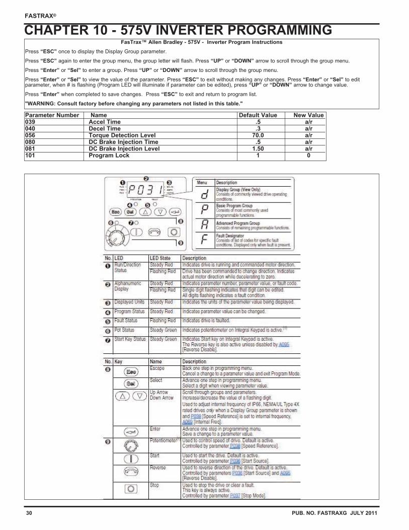
CHAPTER 10 - 575V INVERTER PROGRAMMINGFasTrax™ Allen Bradley - 575V - Inverter Program Instructions
Press “ESC” once to display the Display Group parameter.
Press “ESC” again to enter the group menu, the group letter will flash. Press “UP” or “DOWN” arrow to scroll through the group menu.
Press “Enter” or “Sel” to enter a group. Press “UP” or “DOWN” arrow to scroll through the group menu.
Press “Enter” or “Sel” to view the value of the parameter. Press “ESC” to exit without making any changes. Press “Enter” or “Sel” to editparameter, when # is flashing (Program LED will illuminate if parameter can be edited), press “UP” or “DOWN” arrow to change value.
Press “Enter” when completed to save changes. Press “ESC” to exit and return to program list.
"WARNING: Consult factory before changing any parameters not listed in this table."
Parameter Number Name Default Value New Value039 Accel Time .5 a/r040 Decel Time .3 a/r056 Torque Detection Level 70.0 a/r080 DC Brake Injection Time .5 a/r081 DC Brake Injection Level 1.50 a/r101 Program Lock 1 0
PUB. NO. FASTRAXG JULY 2011 31
FASTRAX®
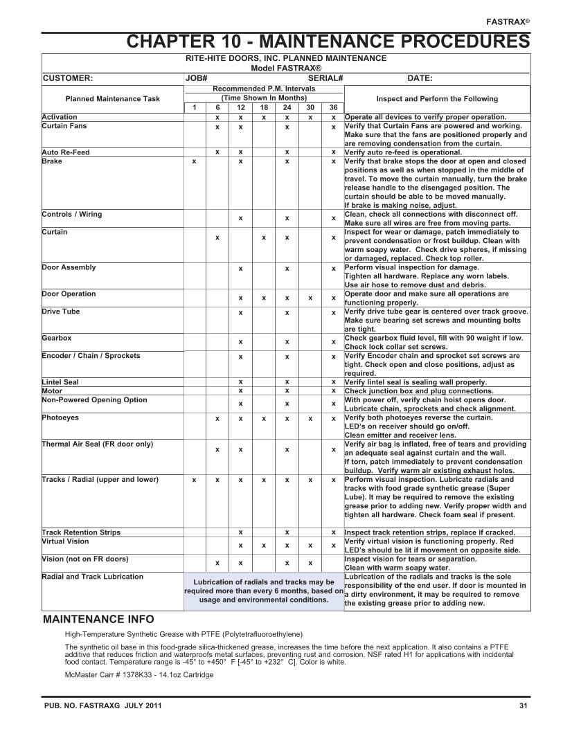
CHAPTER 10 - MAINTENANCE PROCEDURESRITE-HITE DOORS, INC. PLANNED MAINTENANCE
Model FASTRAX®
CUSTOMER: JOB# SERIAL# DATE:
Activation
Curtain Fans
Auto Re-Feed
Brake
Controls / Wiring
Curtain
Door Assembly
Door Operation
Drive Tube
Gearbox
Encoder / Chain / Sprockets
Lintel Seal
Motor
Non-Powered Opening Option
Photoeyes
Thermal Air Seal (FR door only)
Tracks / Radial (upper and lower)
Track Retention Strips
Virtual Vision
Vision (not on FR doors)
Radial and Track Lubrication
Recommended P.M. Intervals
(Time Shown In Months)
Operate all devices to verify proper operation.
Verify that Curtain Fans are powered and working.
Make sure that the fans are positioned properly and
are removing condensation from the curtain.
Verify auto re-feed is operational.
Verify that brake stops the door at open and closed
positions as well as when stopped in the middle of
travel. To move the curtain manually, turn the brake
release handle to the disengaged position. The
curtain should be able to be moved manually.
If brake is making noise, adjust.
Clean, check all connections with disconnect off.
Make sure all wires are free from moving parts.
Inspect for wear or damage, patch immediately to
prevent condensation or frost buildup. Clean with
warm soapy water. Check drive spheres, if missing
or damaged, replaced. Check top roller.
Perform visual inspection for damage.
Tighten all hardware. Replace any worn labels.
Use air hose to remove dust and debris.
Operate door and make sure all operations are
functioning properly.
Verify drive tube gear is centered over track groove.
Make sure bearing set screws and mounting bolts
are tight.
Check gearbox fluid level, fill with 90 weight if low.
Check lock collar set screws.
Verify Encoder chain and sprocket set screws are
tight. Check open and close positions, adjust as
required.
Verify lintel seal is sealing wall properly.
Check junction box and plug connections.
With power off, verify chain hoist opens door.
Lubricate chain, sprockets and check alignment.
Verify both photoeyes reverse the curtain.
LED’s on receiver should go on/off.
Clean emitter and receiver lens.
Verify air bag is inflated, free of tears and providing
an adequate seal against curtain and the wall.
If torn, patch immediately to prevent condensation
buildup. Verify warm air existing exhaust holes.
Perform visual inspection. Lubricate radials and
tracks with food grade synthetic grease (Super
Lube). It may be required to remove the existing
grease prior to adding new. Verify proper width and
tighten all hardware. Check foam seal if present.
Inspect track retention strips, replace if cracked.
Verify virtual vision is functioning properly. Red
LED’s should be lit if movement on opposite side.
Inspect vision for tears or separation.
Clean with warm soapy water.
Lubrication of the radials and tracks is the sole
responsibility of the end user. If door is mounted in
a dirty environment, it may be required to remove
the existing grease prior to adding new.
Planned Maintenance Task Inspect and Perform the Following
x x x x x x
1 6 12 18 24 30 36
MAINTENANCE INFO
High-Temperature Synthetic Grease with PTFE (Polytetrafluoroethylene)
The synthetic oil base in this food-grade silica-thickened grease, increases the time before the next application. It also contains a PTFEadditive that reduces friction and waterproofs metal surfaces, preventing rust and corrosion. NSF rated H1 for applications with incidentalfood contact. Temperature range is -45° to +450° F [-45° to +232° C]. Color is white.
McMaster Carr # 1378K33 - 14.1oz Cartridge
x x x x
x x x x
x x x x
x x x
x x x x
x x x
x x x x x
x x x
x x x
x x x
x x x
x x x
x x x
x x x x x x
x x x x
x x x x
x x x x x
x x x
x x x x x x x
Lubrication of radials and tracks may be
required more than every 6 months, based on
usage and environmental conditions.
32 PUB. NO. FASTRAXG JULY 2011
FASTRAX®
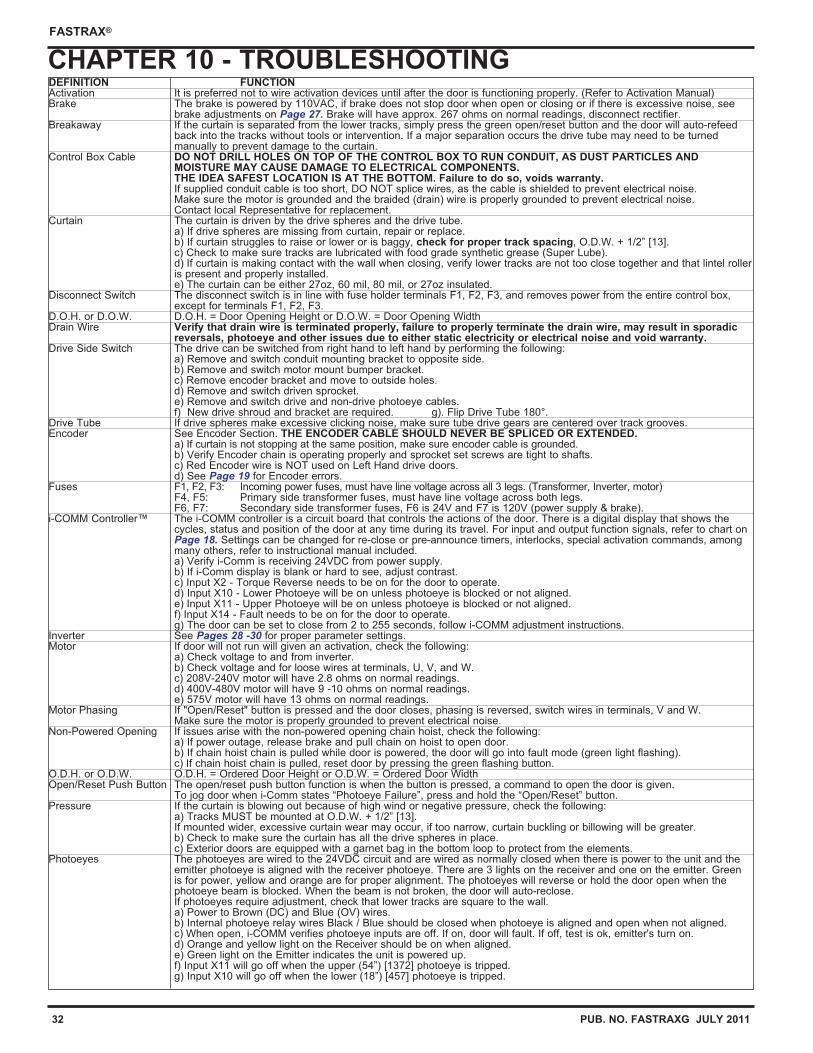
CHAPTER 10 - TROUBLESHOOTINGDEFINITION FUNCTIONActivation It is preferred not to wire activation devices until after the door is functioning properly. (Refer to Activation Manual)Brake The brake is powered by 110VAC, if brake does not stop door when open or closing or if there is excessive noise, see
brake adjustments on Page 27. Brake will have approx. 267 ohms on normal readings, disconnect rectifier.Breakaway If the curtain is separated from the lower tracks, simply press the green open/reset button and the door will auto-refeed
back into the tracks without tools or intervention. If a major separation occurs the drive tube may need to be turned manually to prevent damage to the curtain.
Control Box Cable DO NOT DRILL HOLES ON TOP OF THE CONTROL BOX TO RUN CONDUIT, AS DUST PARTICLES AND MOISTURE MAY CAUSE DAMAGE TO ELECTRICAL COMPONENTS. THE IDEA SAFEST LOCATION IS AT THE BOTTOM. Failure to do so, voids warranty.If supplied conduit cable is too short, DO NOT splice wires, as the cable is shielded to prevent electrical noise. Make sure the motor is grounded and the braided (drain) wire is properly grounded to prevent electrical noise.Contact local Representative for replacement.
Curtain The curtain is driven by the drive spheres and the drive tube.a) If drive spheres are missing from curtain, repair or replace.b) If curtain struggles to raise or lower or is baggy, check for proper track spacing, O.D.W. + 1/2” [13].c) Check to make sure tracks are lubricated with food grade synthetic grease (Super Lube).d) If curtain is making contact with the wall when closing, verify lower tracks are not too close together and that lintel rolleris present and properly installed.e) The curtain can be either 27oz, 60 mil, 80 mil, or 27oz insulated.
Disconnect Switch The disconnect switch is in line with fuse holder terminals F1, F2, F3, and removes power from the entire control box, except for terminals F1, F2, F3.
D.O.H. or D.O.W. D.O.H. = Door Opening Height or D.O.W. = Door Opening WidthDrain Wire Verify that drain wire is terminated properly, failure to properly terminate the drain wire, may result in sporadic
reversals, photoeye and other issues due to either static electricity or electrical noise and void warranty.Drive Side Switch The drive can be switched from right hand to left hand by performing the following:
a) Remove and switch conduit mounting bracket to opposite side.b) Remove and switch motor mount bumper bracket.c) Remove encoder bracket and move to outside holes.d) Remove and switch driven sprocket.e) Remove and switch drive and non-drive photoeye cables.f) New drive shroud and bracket are required. g). Flip Drive Tube 180°.
Drive Tube If drive spheres make excessive clicking noise, make sure tube drive gears are centered over track grooves.Encoder See Encoder Section. THE ENCODER CABLE SHOULD NEVER BE SPLICED OR EXTENDED.
a) If curtain is not stopping at the same position, make sure encoder cable is grounded.b) Verify Encoder chain is operating properly and sprocket set screws are tight to shafts.c) Red Encoder wire is NOT used on Left Hand drive doors.d) See Page 19 for Encoder errors.
Fuses F1, F2, F3: Incoming power fuses, must have line voltage across all 3 legs. (Transformer, Inverter, motor)F4, F5: Primary side transformer fuses, must have line voltage across both legs.F6, F7: Secondary side transformer fuses, F6 is 24V and F7 is 120V (power supply & brake).
i-COMM Controller™ The i-COMM controller is a circuit board that controls the actions of the door. There is a digital display that shows the cycles, status and position of the door at any time during its travel. For input and output function signals, refer to chart on Page 18. Settings can be changed for re-close or pre-announce timers, interlocks, special activation commands, among many others, refer to instructional manual included.a) Verify i-Comm is receiving 24VDC from power supply.b) If i-Comm display is blank or hard to see, adjust contrast.c) Input X2 - Torque Reverse needs to be on for the door to operate.d) Input X10 - Lower Photoeye will be on unless photoeye is blocked or not aligned.e) Input X11 - Upper Photoeye will be on unless photoeye is blocked or not aligned.f) Input X14 - Fault needs to be on for the door to operate.g) The door can be set to close from 2 to 255 seconds, follow i-COMM adjustment instructions.
Inverter See Pages 28 -30 for proper parameter settings.Motor If door will not run will given an activation, check the following:
a) Check voltage to and from inverter.b) Check voltage and for loose wires at terminals, U, V, and W.c) 208V-240V motor will have 2.8 ohms on normal readings.d) 400V-480V motor will have 9 -10 ohms on normal readings.e) 575V motor will have 13 ohms on normal readings.
Motor Phasing If "Open/Reset" button is pressed and the door closes, phasing is reversed, switch wires in terminals, V and W.Make sure the motor is properly grounded to prevent electrical noise.
Non-Powered Opening If issues arise with the non-powered opening chain hoist, check the following:a) If power outage, release brake and pull chain on hoist to open door.b) If chain hoist chain is pulled while door is powered, the door will go into fault mode (green light flashing).c) If chain hoist chain is pulled, reset door by pressing the green flashing button.
O.D.H. or O.D.W. O.D.H. = Ordered Door Height or O.D.W. = Ordered Door WidthOpen/Reset Push Button The open/reset push button function is when the button is pressed, a command to open the door is given.
To jog door when i-Comm states “Photoeye Failure”, press and hold the “Open/Reset” button.Pressure If the curtain is blowing out because of high wind or negative pressure, check the following:
a) Tracks MUST be mounted at O.D.W. + 1/2” [13]. If mounted wider, excessive curtain wear may occur, if too narrow, curtain buckling or billowing will be greater.b) Check to make sure the curtain has all the drive spheres in place.c) Exterior doors are equipped with a garnet bag in the bottom loop to protect from the elements.
Photoeyes The photoeyes are wired to the 24VDC circuit and are wired as normally closed when there is power to the unit and the emitter photoeye is aligned with the receiver photoeye. There are 3 lights on the receiver and one on the emitter. Green is for power, yellow and orange are for proper alignment. The photoeyes will reverse or hold the door open when the photoeye beam is blocked. When the beam is not broken, the door will auto-reclose. If photoeyes require adjustment, check that lower tracks are square to the wall.a) Power to Brown (DC) and Blue (OV) wires.b) Internal photoeye relay wires Black / Blue should be closed when photoeye is aligned and open when not aligned.c) When open, i-COMM verifies photoeye inputs are off. If on, door will fault. If off, test is ok, emitter's turn on.d) Orange and yellow light on the Receiver should be on when aligned.e) Green light on the Emitter indicates the unit is powered up.f) Input X11 will go off when the upper (54”) [1372] photoeye is tripped.g) Input X10 will go off when the lower (18”) [457] photoeye is tripped.
PUB. NO. FASTRAXG JULY 2011 33
FASTRAX®
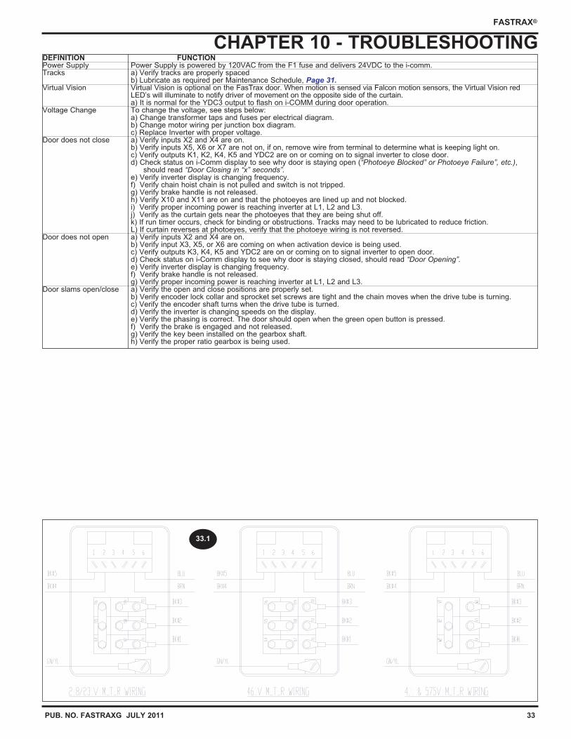
CHAPTER 10 - TROUBLESHOOTINGDEFINITION FUNCTIONPower Supply Power Supply is powered by 120VAC from the F1 fuse and delivers 24VDC to the i-comm. Tracks a) Verify tracks are properly spaced
b) Lubricate as required per Maintenance Schedule, Page 31.Virtual Vision Virtual Vision is optional on the FasTrax door. When motion is sensed via Falcon motion sensors, the Virtual Vision red
LED’s will illuminate to notify driver of movement on the opposite side of the curtain.a) It is normal for the YDC3 output to flash on i-COMM during door operation.
Voltage Change To change the voltage, see steps below:a) Change transformer taps and fuses per electrical diagram.b) Change motor wiring per junction box diagram.c) Replace Inverter with proper voltage.
Door does not close a) Verify inputs X2 and X4 are on.b) Verify inputs X5, X6 or X7 are not on, if on, remove wire from terminal to determine what is keeping light on.c) Verify outputs K1, K2, K4, K5 and YDC2 are on or coming on to signal inverter to close door.d) Check status on i-Comm display to see why door is staying open (“Photoeye Blocked” or Photoeye Failure”, etc.),
should read “Door Closing in “x” seconds”.e) Verify inverter display is changing frequency.f) Verify chain hoist chain is not pulled and switch is not tripped.g) Verify brake handle is not released.h) Verify X10 and X11 are on and that the photoeyes are lined up and not blocked.i) Verify proper incoming power is reaching inverter at L1, L2 and L3.j) Verify as the curtain gets near the photoeyes that they are being shut off.k) If run timer occurs, check for binding or obstructions. Tracks may need to be lubricated to reduce friction.L) If curtain reverses at photoeyes, verify that the photoeye wiring is not reversed.
Door does not open a) Verify inputs X2 and X4 are on.b) Verify input X3, X5, or X6 are coming on when activation device is being used.c) Verify outputs K3, K4, K5 and YDC2 are on or coming on to signal inverter to open door.d) Check status on i-Comm display to see why door is staying closed, should read “Door Opening”.e) Verify inverter display is changing frequency.f) Verify brake handle is not released.g) Verify proper incoming power is reaching inverter at L1, L2 and L3.
Door slams open/close a) Verify the open and close positions are properly set.b) Verify encoder lock collar and sprocket set screws are tight and the chain moves when the drive tube is turning.c) Verify the encoder shaft turns when the drive tube is turned.d) Verify the inverter is changing speeds on the display.e) Verify the phasing is correct. The door should open when the green open button is pressed.f) Verify the brake is engaged and not released.g) Verify the key been installed on the gearbox shaft.h) Verify the proper ratio gearbox is being used.
33.1
34 PUB. NO. FASTRAXG JULY 2011
FASTRAX®
CHAPTER 11- MANDATORY FIELD WIRING DIAGRAM
7822
E02
2
RIT
E-H
ITE
DO
OR
S IN
C.
4"=
1'
C
FA
ST
RA
X F
IELD
WIR
ING
EN
CO
DE
R
MD
B6/
2/20
09
5866
6/10
/201
0
2009
AC
E IS
OLA
TIO
N R
ELA
Y61
378/
16/2
010
LIP
BM
OT
OR
CA
BLE
CH
AN
GE
6150
8/30
/201
0R
PB
CIs
olat
e w
hite
wire
6166
9/8/
2010
MD
B
CO
NN
EC
T R
ED
WIR
E
TO
DC
FO
R R
IGH
T
HA
ND
DR
IVE
DO
OR
S.
ISO
LAT
E R
ED
WIR
E
FO
R L
EF
T H
AN
D
DR
IVE
DO
OR
S.
BLA
CK
CA
BLE
18"
PH
OT
OE
YE
BLA
CK
CA
BLE
BLA
CK
CA
BLE
54"
PH
OT
OE
YE
BLA
CK
CA
BLE
BLA
CK
CA
BLE
BLA
CK
CA
BLE
GR
AY
CA
BLE
GR
AY
CA
BLE
Gro
un
d
wir
e M
US
Tb
e
gro
un
ded
Fro
mcab
le l
ab
ele
d18” p
ho
toeye
Fro
mcab
le l
ab
ele
d54” p
ho
toeye
PUB. NO. FASTRAXG JULY 2011 35
FASTRAX®
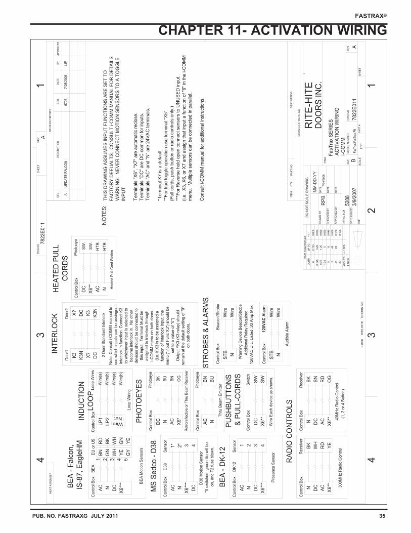
CHAPTER 11- ACTIVATION WIRING
TH
IS D
RA
WIN
G A
SS
UM
ES
IN
PU
T F
UN
CT
ION
S A
RE
SE
T T
O
FA
CT
OR
Y D
EF
UA
LT
S.
CO
NS
UL
T i-
CO
MM
MA
NU
AL
FO
R D
ET
AIL
S
WA
RN
ING
: N
EV
ER
CO
NN
EC
T M
OT
ION
SE
NS
OR
S T
O A
TO
GG
LE
INP
UT
Term
inals
"X
6",
"X
7"
are
auto
matic
recl
ose
.
Term
inals
"D
C"
are
DC
com
mon for
inputs
.
Term
inals
"A
C"
and "
N"
are
24V
AC
term
inals
.
*Term
inal X
7 is
a d
efa
ult
**F
or
true toggle
opera
tion u
se term
inal "
X5".
(Pull
cord
s, push
button o
r ra
dio
contr
ols
only
.)
***F
or
Reve
rse h
old
open c
onnect se
nsors
to U
NU
SE
D in
put.
(i.e
. X
3, X
6, or
X7 a
nd a
ssi
gn that in
put a functio
n o
f "6
" in
the i-
CO
MM
menu. M
ulti
ple
senso
rs c
an b
e c
onnecte
d in
para
llel.
Consu
lt i-C
OM
M m
anual f
or
additi
onal i
nst
ruct
ions.
Contr
ol B
ox
Warn
ing D
evi
ce B
eaco
n/S
trobe
120V
AC
U.L
. Lis
ted .30 A
mp M
ax
Addito
nal R
ela
y R
equired
N
ST
B
Note
: C
onsu
lt i-C
OM
M m
anual t
o
see w
hic
h in
puts
can b
e a
ssin
ged
inte
rlock
in funct
ion. C
onnect
K3
to w
hic
heve
r in
put is
sele
cted to
beco
me in
terlock
in. N
o o
ther
devi
ces
should
be c
onnect
ed to
this
input. T
erm
inal M
ust
be
ass
igned to Inte
rlock
thro
ugh
i-C
OM
M m
enu o
n b
oth
doors
.
(i.e
. If X
3 is
to b
e a
ssig
ned a
funct
ion o
f In
terlock
Input, the
menu (
"Input F
unc
X3")
should
be
set to
a v
alu
e o
f "0
")
Outp
ut Y
K3 (
K3 r
ela
y) s
hould
rem
ain
at th
e d
efa
ult
settin
g o
f "0
"
on b
oth
doors
.
2 D
oor
Sta
ndard
Inte
rlock
DC
K3N
X?
K3
Door1
K3N
Door2
DC
X?
K3
Wire
Beaco
n/S
trobe
Wire
Contr
ol B
ox
Contr
ol B
ox
Contr
ol B
ox
BE
A M
otio
n S
enso
rs
Pre
sence
Senso
r
D38 M
otio
n S
enso
r
on, and F
2 fuse
blo
wn.
*If sw
itched, gre
en li
te w
ill b
e
X6**
*
DC
X6**
*
NAC
DCNAC
DC
X6**
*
AC N
Contr
ol B
ox
Retr
ore
flect
ive o
r T
hru
Beam
Rece
iver
Contr
ol B
ox
Contr
ol B
ox
Thru
Beam
Em
itter
Audib
le A
larm
(1, 2 o
r 4 B
utton)
Contr
ol B
ox
Loop W
irin
g
Wire E
ach
devi
ce a
s sh
ow
n.
Contr
ol B
ox
3 4X
6**
DC
Senso
rD
K12
21
Wire
Nut
LP
2
LP
1
ST
B
Sw
itch
SW
SW
N
Loop W
ires
Wire(a
)
Wire(b
)
Wire(a
)
Wire(b
)
AC N
300M
Hz
Radio
Contr
ol
Contr
ol B
ox
40M
Hz
Radio
Contr
ol
Contr
ol B
ox
X6**
ACN DC
1*
Senso
r
42*
D38
3
X6**
ACN DC
Rece
iver
BK
OG
RD
BN
X6*
ACNDC
Rece
iver
BK
YE
RD
WH
Wire
Wire
Photo
eye
120V
AC
Ala
rm
BN
BU
Photo
eye
OG
BN
BU
BK
MS
Se
dco
- D
38
BE
A -
Falc
on,
IS
-87
, E
agle
HM
BE
A -
DK
-12
RA
DIO
CO
NT
RO
LS
IND
UC
TIO
N
LO
OP
PH
OT
OE
YE
S
PU
SH
BU
TT
ON
S
& P
UL
L-C
OR
DS
ST
RO
BE
S &
ALA
RM
S
NO
TE
S:
INT
ER
LO
CK
7822E
011
7822E
011
RIT
E-H
ITE
DO
OR
S IN
C.
8"=
1'
A
A
FasT
rax S
ER
IES
AC
TIV
AT
ION
WIR
ING
i-C
OM
M
RP
B7
/24
/2008
5288
3/9
/2007
20
08
AU
PD
AT
E F
ALC
ON
5705
7/2
5/2
008
LIP
Contr
ol B
ox
Heate
d P
ull-
Cord
Sta
tion
NAC
X6**
DC
Photo
eye
HT
R.
HT
R.
SW
.
SW
.
HE
AT
ED
PU
LL
CO
RD
S
2 43
BE
A
1E
U o
r U
S
GN
YE
WH
BN
BK
GN
WH
RD
GY
YE
5
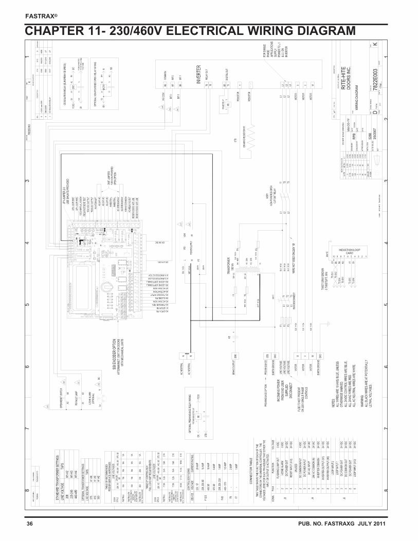
36 PUB. NO. FASTRAXG JULY 2011
FASTRAX®
CHAPTER 11- 230/460V ELECTRICAL WIRING DIAGRAM
78
22
E00
3
7822
E00
3
RIT
E-H
ITE
DO
OR
S IN
C.
9"=
1'
K
K
WIR
ING
DIA
GR
AM 17
44...
.
RP
B7/
27/2
006
5288
3/9/
2007
2006
K=
22
0V
, wa
s 23
0V6
16
69
/8/2
010
MD
B
HE
NC
OD
ER
58
66
5/1
1/2
010
LIP
JC
E IS
OL
AT
ION
RE
LAY
61
37
8/1
6/2
010
LIP
FIN
AL
AS
SE
MB
LY
CO
NN
EC
TO
R T
AB
LE
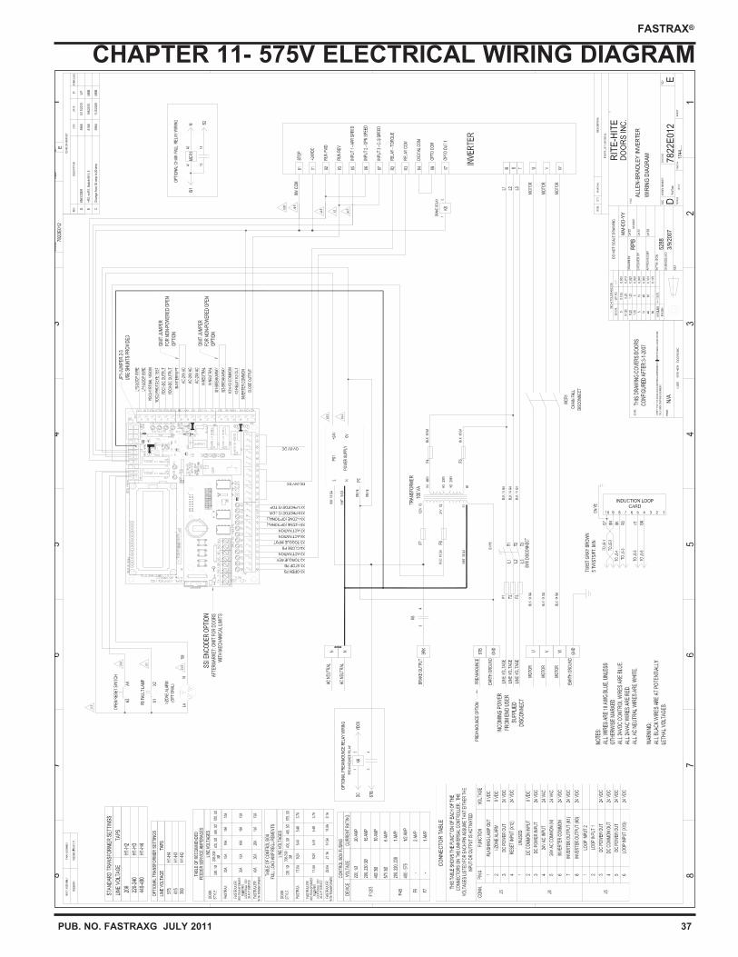
PUB. NO. FASTRAXG JULY 2011 37
FASTRAX®
CHAPTER 11- 575V ELECTRICAL WIRING DIAGRAM
CO
NN
EC
TO
R T
AB
LE
78
22
E01
2
7822
E01
2
RIT
E-H
ITE
DO
OR
S IN
C.
9"=
1'
E
E
ALLE
N-B
RA
DLE
Y IN
VE
RT
ER
WIR
ING
DIA
GR
AM 17
44...
.
RP
B3/
13/2
007
5288
3/9/
2007
2007
DE
NC
OD
ER
58
66
5/1
1/2
010
LIP
E=
R3
, vs
R1
, Sw
itch
K8
1, 5
61
66
9/8
/20
10M
DB
CC
ha
ng
e fr
om
30
am
p to
20
amp
59
64
11
/2/2
009
MD
B
N/A
PR
IOR
FIN
AL
AS
SE
MB
LY
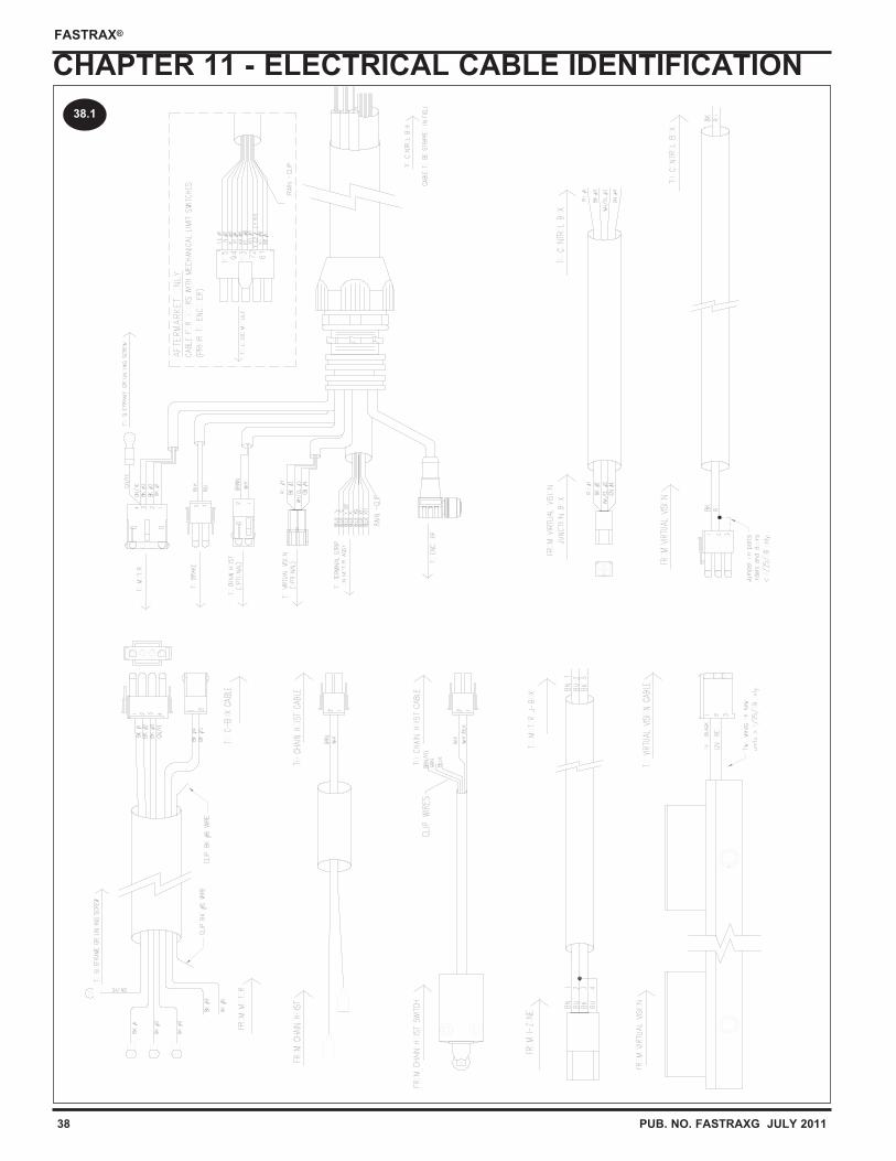
38 PUB. NO. FASTRAXG JULY 2011
FASTRAX®
CHAPTER 11 - ELECTRICAL CABLE IDENTIFICATION
38.1
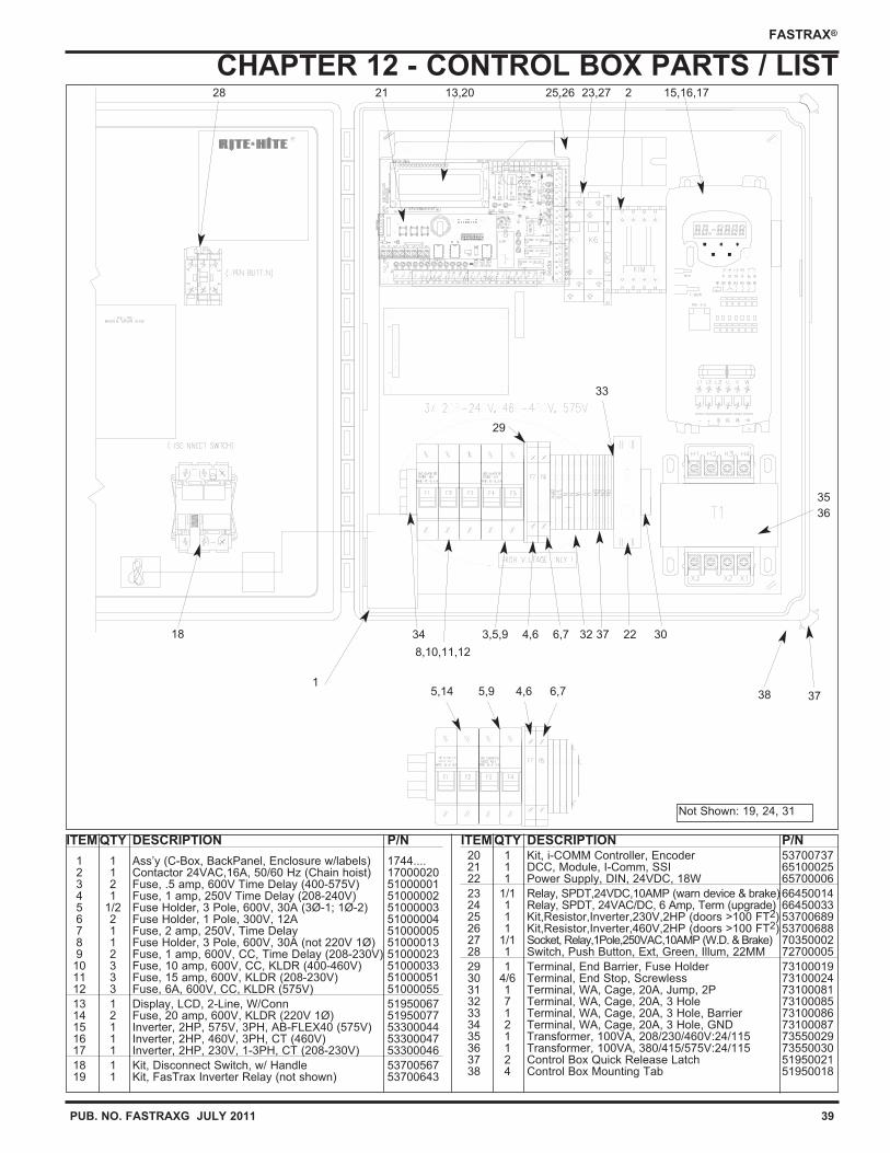
PUB. NO. FASTRAXG JULY 2011 39
FASTRAX®
CHAPTER 12 - CONTROL BOX PARTS / LIST
ITEM QTY DESCRIPTION P/N
1 1 Ass’y (C-Box, BackPanel, Enclosure w/labels) 1744....2 1 Contactor 24VAC,16A, 50/60 Hz (Chain hoist) 170000203 2 Fuse, .5 amp, 600V Time Delay (400-575V) 510000014 1 Fuse, 1 amp, 250V Time Delay (208-240V) 510000025 1/2 Fuse Holder, 3 Pole, 600V, 30A (3Ø-1; 1Ø-2) 510000036 2 Fuse Holder, 1 Pole, 300V, 12A 510000047 1 Fuse, 2 amp, 250V, Time Delay 510000058 1 Fuse Holder, 3 Pole, 600V, 30A (not 220V 1Ø) 510000139 2 Fuse, 1 amp, 600V, CC, Time Delay (208-230V) 51000023
10 3 Fuse, 10 amp, 600V, CC, KLDR (400-460V) 5100003311 3 Fuse, 15 amp, 600V, KLDR (208-230V) 5100005112 3 Fuse, 6A, 600V, CC, KLDR (575V) 51000055
13 1 Display, LCD, 2-Line, W/Conn 5195006714 2 Fuse, 20 amp, 600V, KLDR (220V 1Ø) 5195007715 1 Inverter, 2HP, 575V, 3PH, AB-FLEX40 (575V) 5330004416 1 Inverter, 2HP, 460V, 3PH, CT (460V) 5330004717 1 Inverter, 2HP, 230V, 1-3PH, CT (208-230V) 53300046
18 1 Kit, Disconnect Switch, w/ Handle 5370056719 1 Kit, FasTrax Inverter Relay (not shown) 53700643
ITEM QTY DESCRIPTION P/N20 1 Kit, i-COMM Controller, Encoder 5370073721 1 DCC, Module, I-Comm, SSI 6510002522 1 Power Supply, DIN, 24VDC, 18W 65700006
23 1/1 Relay, SPDT,24VDC,10AMP (warn device & brake) 6645001424 1 Relay, SPDT, 24VAC/DC, 6 Amp, Term (upgrade) 6645003325 1 Kit,Resistor,Inverter,230V,2HP (doors >100 FT2) 5370068926 1 Kit,Resistor,Inverter,460V,2HP (doors >100 FT2) 5370068827 1/1 Socket, Relay,1Pole,250VAC,10AMP (W.D. & Brake) 7035000228 1 Switch, Push Button, Ext, Green, Illum, 22MM 72700005
29 1 Terminal, End Barrier, Fuse Holder 7310001930 4/6 Terminal, End Stop, Screwless 7310002431 1 Terminal, WA, Cage, 20A, Jump, 2P 7310008132 7 Terminal, WA, Cage, 20A, 3 Hole 7310008533 1 Terminal, WA, Cage, 20A, 3 Hole, Barrier 7310008634 2 Terminal, WA, Cage, 20A, 3 Hole, GND 7310008735 1 Transformer, 100VA, 208/230/460V:24/115 7355002936 1 Transformer, 100VA, 380/415/575V:24/115 7355003037 2 Control Box Quick Release Latch 5195002138 4 Control Box Mounting Tab 51950018
18
28 21 13,20 25,26 23,27 2 15,16,17
35
36
34 3,5,9 4,6 6,7 32 37 22 30
15,14 5,9 4,6 6,7
Not Shown: 19, 24, 31
29
33
8,10,11,12
3738
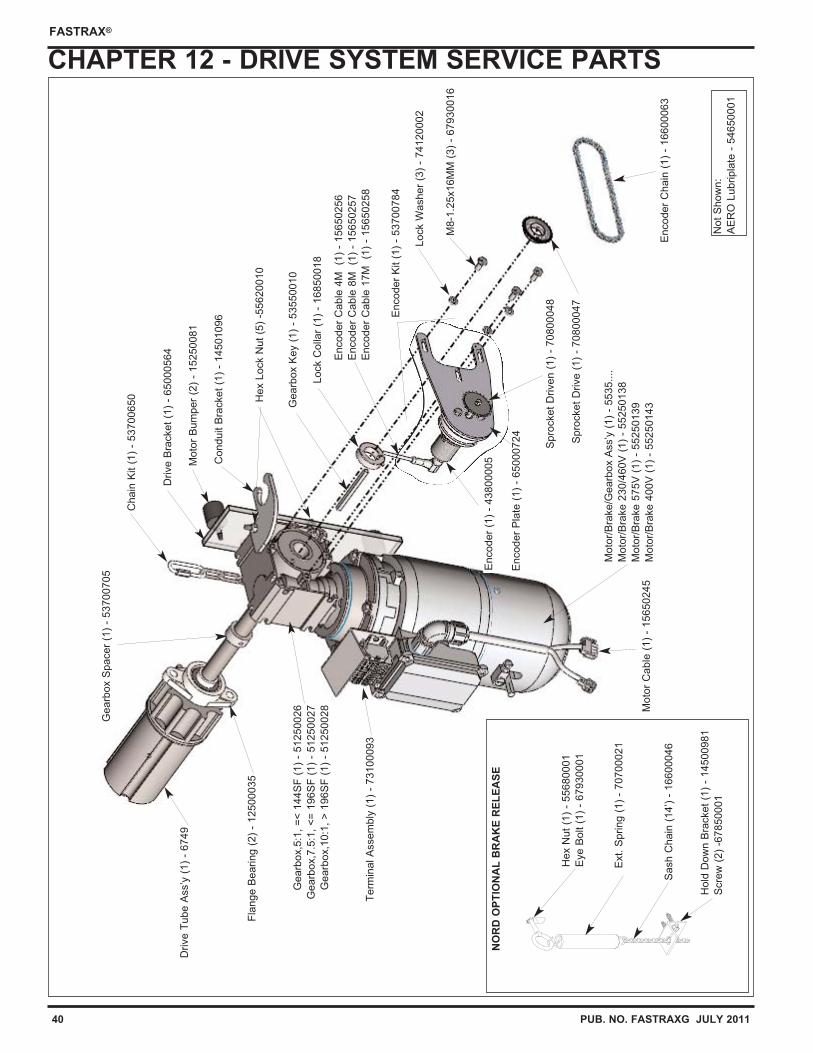
40 PUB. NO. FASTRAXG JULY 2011
FASTRAX®
CHAPTER 12 - DRIVE SYSTEM SERVICE PARTS
Lo
ck C
olla
r (1
) -
16850018
Encoder
Pla
te (
1)
- 65000724
Spro
cket
Drive (
1)
- 70800047
Lock W
asher
(3)
- 74120002
M8-1
.25x16M
M (
3)
- 67930016
Encoder
Chain
(1)
- 16600063
Gearb
ox K
ey (
1)
- 53550010
Encoder
(1)
- 43800005
Moto
r C
able
(1)
- 15650245
Fla
nge B
earing (
2)
- 12500035
Conduit B
racket
(1)
- 14501096
Drive T
ube A
ss’y
(1)
- 6749
Moto
r B
um
per
(2)
- 1
5250081
Spro
cket
Driven (
1)
- 70800048
Gearb
ox S
pacer
(1)
- 53700705
Not
Show
n:
AE
RO
Lubripla
te -
54650001
Drive B
racket
(1)
- 65000564
Chain
Kit (
1)
- 53700650
Hex N
ut
(1)
- 55680001
Eye B
olt (
1)
- 67930001
Ext. S
pring (
1)
- 70700021
Sash C
hain
(14’) -
16600046
Ho
ld D
ow
n B
racket
(1)
- 14500981
Scre
w (
2)
-67850001
Term
inal A
ssem
bly
(1)
- 73100093
Moto
r/B
rake/G
earb
ox A
ss’y
(1)
- 5535....
Moto
r/B
rake 2
30/4
60V
(1)
- 55250138
Moto
r/B
rake 5
75V
(1)
- 55250139
Moto
r/B
rake 4
00V
(1)
- 55250143
Gearb
ox,5
:1,
=<
144S
F (
1)
- 5125002
6
Gearb
ox,7
.5:1
, <
= 1
96S
F (
1)
- 5125002
7
Gearb
ox,1
0:1
, >
196S
F (
1)
- 5125002
8
NO
RD
OP
TIO
NA
L B
RA
KE
RE
LE
AS
E
Encoder
Kit (
1)
- 53700784
Hex L
ock N
ut
(5)
-55620010
Encoder
Cable
4M
(1
) -
15650256
Encoder
Cable
8M
(1
) -
15650257
Encoder
Cable
17M
(1
) -
15650258
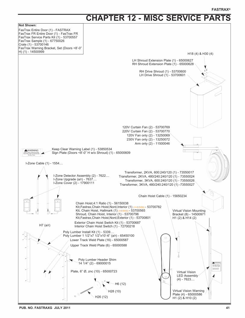
PUB. NO. FASTRAXG JULY 2011 41
FASTRAX®
CHAPTER 12 - MISC SERVICE PARTS
Do Not Enter On Red Light
Personnel Or Equipment May Be Present On The
Other Side Of The Door
WARNING
WARNINGKeep Clear of Moving Parts.
Door May Start Automatically
At Any Time.
Not Shown:
FasTrax Entire Door (1) - FASTRAXFasTrax FR Entire Door (1) - FasTrax FRFasTrax Service Parts Kit (1) - 53700557FasTrax Sample (1) - 67750026Crate (1) - 53700146FasTrax Warning Bracket, Set (Doors <8’-0”H) (1) - 14500999
RH Drive Shroud (1) - 53700600LH Drive Shroud (1) - 53700601
H7 (a/r)
Upper Track Weld Plate (6) - 65000588
Poly Lumber Header Shim14 1/4” (2) - 69000015
H6 (12)
Poly Lumber Install Kit (1) - 5339....Poly Lumber 1 1/2”x7 1/2”x10’-6” (a/r) - 65450100
Plate, 6” Ø, znc (10) - 65000723
Lower Track Weld Plate (16) - 65000587
Transformer, 2KVA, 600:240/120 (1) - 73550017
Transformer, 2KVA, 480/240:240/120 (1) - 73550024
Transformer, 3KVA, 600:240/120 (1) - 73550026
Transformer, 3KVA, 480/240:240/120 (1) -73550027
Virtual VisionLED Assembly(4) - 7623....
120V Curtain Fan (2) - 53700769
220V Curtain Fan (2) - 53700770
120V Fan only (2) - 13250069
230V Fan only (2) - 13250072
Arm only (2) - 11500046
Chain Hoist Cable (1) - 15650234
I-Zone Detector Assembly (2) - 7622....I-Zone Upgrade (a/r) - 7637....I-Zone Cover (2) - 17900111
I-Zone Cable (1) - 1554....
LH Shroud Extension Plate (1) - 65000627RH Shroud Extension Plate (1) - 65000628
H18 (4) & H30 (4)
Virtual Vision MountingBracket (8) - 14500971H1 (2) & H14 (2)
Keep Clear Warning Label (1) - 53850534Sign Plate (Doors <8’-0” H w/o Shroud) (1) - 65000609
Chain Hoist,4:1 Ratio (1) - 56150038Kit,Fastrax,Chain Hoist,Nord,Interior (1) (=>8/5/09) - 53700782Kit, Chain Hoist, Hallmark (1) (<8/5/09) - 53700565Shroud, Chain Hoist, Interior (1) - 53700796Kit,Fastrax,Chain Hoist,Nord,Exterior (1) - 53700801
Virtual Vision WarningPlate (4) - 65000586H1 (2) & H10 (2)
H28 (10)
Exterior Chain Hoist Switch Kit (1) - 53700687Interior Chain Hoist Switch (1) - 72700218
H26 (12)
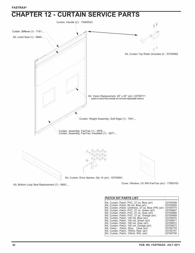
42 PUB. NO. FASTRAXG JULY 2011
FASTRAX®
CHAPTER 12 - CURTAIN SERVICE PARTS
Curtain, Assembly, FasTrax (1) - 2876.... Curtain, Assembly, FasTrax, Insulated (1) - 2877....
Curtain, Weight Assembly, Soft Edge (1) - 7541....
Curtain, Stiffener (1) - 7181....
Kit, Curtain, Drive Sphere, Qty 10 (a/r) - 53700561
Curtain, Handle (2’) - 75000023
Kit, Curtain Top Roller (includes 2) - 53700562
Kit, Lintel Seal (1) - 6890....
Kit, Vision Replacement, 20” x 20” (a/r) -53700711(used on doors that currently do not have replaceable visions)
Cover, Window, UV INH,FasTrax (a/r) - 17900163Kit, Bottom Loop Seal Replacement (1) - 6893....
PATCH KIT PARTS LIST
Kit, Curtain, Patch, PVC, 27 oz, Blue (a/r) 53700558Kit, Curtain, Patch, 60 mil, Blue (a/r) 53700559Kit, Curtain, Patch, Urethane, 27 oz, Blue (FR) (a/r) 53700774Kit, Curtain, Patch, PVC, 27 oz, Green (a/r) 53700667Kit, Curtain, Patch, PVC, 27 oz, Gray (a/r) 53700668Kit, Curtain, Patch, PVC, 27 oz, Orange (a/r) 53700669Kit, Curtain, Patch, 100 mil, Blue (a/r) 53700670Kit, Curtain, Patch, 100 mil, Green (a/r) 53700671Kit, Curtain, Patch, 100 mil, Gray (a/r) 53700672Kit, Curtain, Patch, 100 mil, Orange (a/r) 53700673Kit, Vision, Patch, 30oz, Clear (a/r) 53700778Kit, Curtain, Patch, 100mil, Red, (a/r) 53700757Kit, Curtain, Patch, 100mil, Wht, (a/r) 53700758
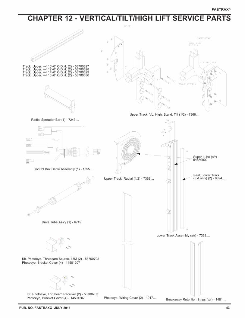
PUB. NO. FASTRAXG JULY 2011 43
FASTRAX®
CHAPTER 12 - VERTICAL/TILT/HIGH LIFT SERVICE PARTS
Upper Track, Radial (1/2) - 7368....
Control Box Cable Assembly (1) - 1555....
Photoeye, Wiring Cover (2) - 1917....
Kit, Photoeye, Thrubeam Source, 13M (2) - 53700702
Photoeye, Bracket Cover (4) - 14501207
Kit, Photoeye, Thrubeam Receiver (2) - 53700703
Photoeye, Bracket Cover (4) - 14501207
Radial Spreader Bar (1) - 7243....
Breakaway Retention Strips (a/r) - 1481....
Track, Upper, =< 10’-0” O.D.H. (2) - 53700627Track, Upper, =< 12’-0” O.D.H. (2) - 53700628Track, Upper, =< 14’-0” O.D.H. (2) - 53700629Track, Upper, =< 16’-0” O.D.H. (2) - 53700630
Lower Track Assembly (a/r) - 7362....
Drive Tube Ass’y (1) - 6749
Upper Track, VL, High, Stand, Tilt (1/2) - 7368....
Seal, Lower Track(Ext only) (2) - 6894....
Super Lube (a/r) -54650002
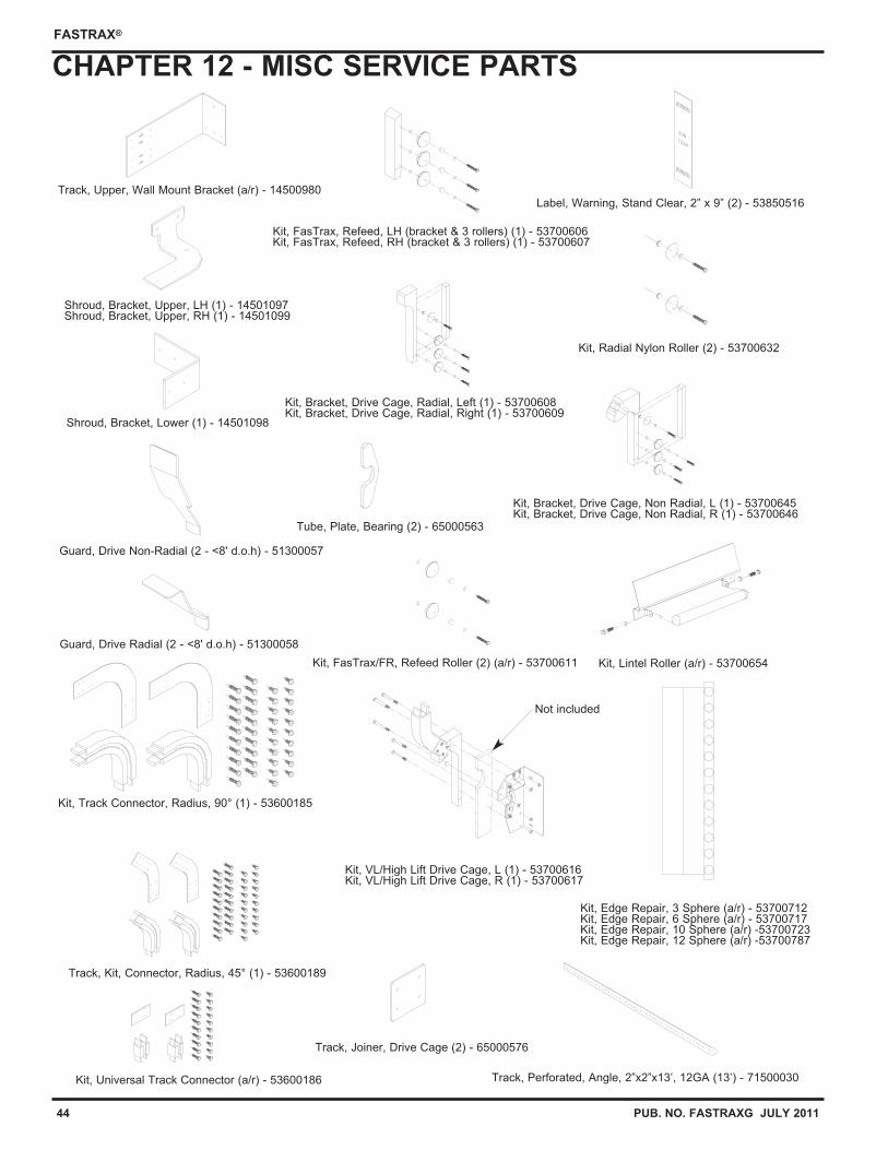
44 PUB. NO. FASTRAXG JULY 2011
FASTRAX®
CHAPTER 12 - MISC SERVICE PARTS
Kit, Edge Repair, 3 Sphere (a/r) - 53700712Kit, Edge Repair, 6 Sphere (a/r) - 53700717Kit, Edge Repair, 10 Sphere (a/r) -53700723Kit, Edge Repair, 12 Sphere (a/r) -53700787
Kit, FasTrax, Refeed, LH (bracket & 3 rollers) (1) - 53700606Kit, FasTrax, Refeed, RH (bracket & 3 rollers) (1) - 53700607
Kit, FasTrax/FR, Refeed Roller (2) (a/r) - 53700611
Kit, Bracket, Drive Cage, Radial, Left (1) - 53700608Kit, Bracket, Drive Cage, Radial, Right (1) - 53700609
Kit, VL/High Lift Drive Cage, L (1) - 53700616Kit, VL/High Lift Drive Cage, R (1) - 53700617
Kit, Radial Nylon Roller (2) - 53700632
Kit, Bracket, Drive Cage, Non Radial, L (1) - 53700645Kit, Bracket, Drive Cage, Non Radial, R (1) - 53700646
Not included
Shroud, Bracket, Upper, LH (1) - 14501097Shroud, Bracket, Upper, RH (1) - 14501099
Shroud, Bracket, Lower (1) - 14501098
Guard, Drive Non-Radial (2 - <8' d.o.h) - 51300057
Guard, Drive Radial (2 - <8' d.o.h) - 51300058
Kit, Lintel Roller (a/r) - 53700654
Track, Perforated, Angle, 2”x2”x13’, 12GA (13’) - 71500030
Track, Upper, Wall Mount Bracket (a/r) - 14500980
Kit, Universal Track Connector (a/r) - 53600186
Kit, Track Connector, Radius, 90° (1) - 53600185
Track, Kit, Connector, Radius, 45° (1) - 53600189
Label, Warning, Stand Clear, 2” x 9” (2) - 53850516
Track, Joiner, Drive Cage (2) - 65000576
Tube, Plate, Bearing (2) - 65000563
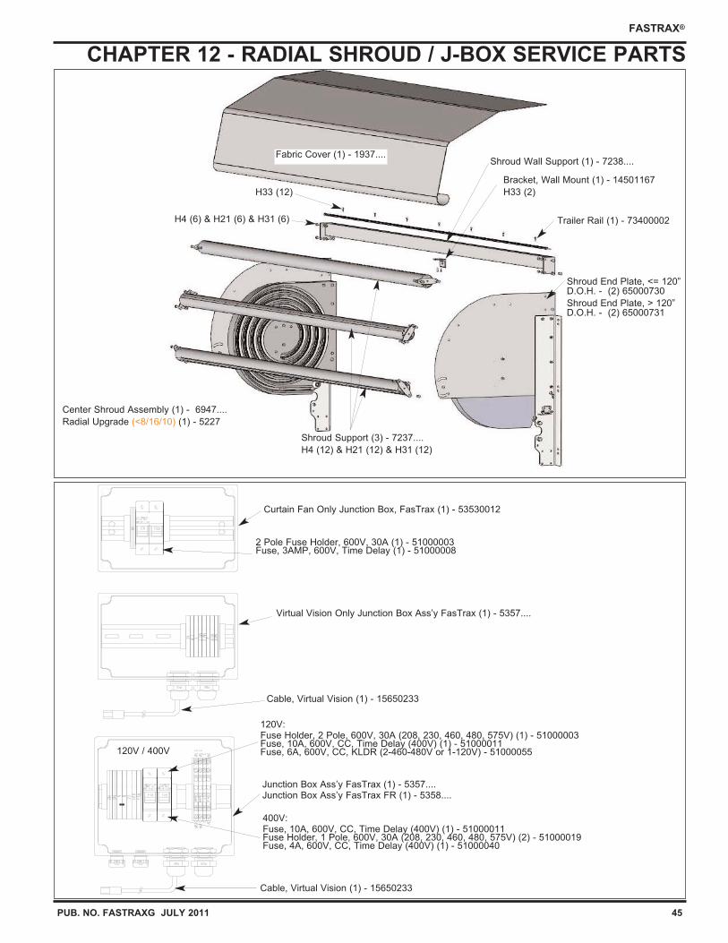
PUB. NO. FASTRAXG JULY 2011 45
FASTRAX®
CHAPTER 12 - RADIAL SHROUD / J-BOX SERVICE PARTS
Fabric Cover (1) - 1937....Shroud Wall Support (1) - 7238....
Shroud Support (3) - 7237....
H4 (12) & H21 (12) & H31 (12)
Bracket, Wall Mount (1) - 14501167
H33 (2)
H4 (6) & H21 (6) & H31 (6) Trailer Rail (1) - 73400002
H33 (12)
Center Shroud Assembly (1) - 6947....
Radial Upgrade (<8/16/10) (1) - 5227
Shroud End Plate, <= 120”D.O.H. - (2) 65000730
Shroud End Plate, > 120”D.O.H. - (2) 65000731
120V / 400V
Cable, Virtual Vision (1) - 15650233
400V:Fuse, 10A, 600V, CC, Time Delay (400V) (1) - 51000011Fuse Holder, 1 Pole, 600V, 30A (208, 230, 460, 480, 575V) (2) - 51000019Fuse, 4A, 600V, CC, Time Delay (400V) (1) - 51000040
120V:Fuse Holder, 2 Pole, 600V, 30A (208, 230, 460, 480, 575V) (1) - 51000003Fuse, 10A, 600V, CC, Time Delay (400V) (1) - 51000011Fuse, 6A, 600V, CC, KLDR (2-460-480V or 1-120V) - 51000055
Junction Box Ass’y FasTrax (1) - 5357....Junction Box Ass’y FasTrax FR (1) - 5358....
Virtual Vision Only Junction Box Ass’y FasTrax (1) - 5357....
Curtain Fan Only Junction Box, FasTrax (1) - 53530012
2 Pole Fuse Holder, 600V, 30A (1) - 51000003Fuse, 3AMP, 600V, Time Delay (1) - 51000008
Cable, Virtual Vision (1) - 15650233
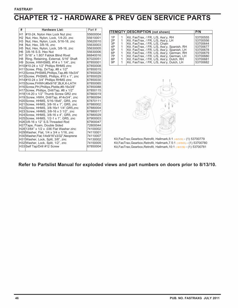
46 PUB. NO. FASTRAXG JULY 2011
FASTRAX®
CHAPTER 12 - HARDWARE & PREV GEN SERVICE PARTS
ITEM QTY DESCRIPTION (not shown) P/N
1P 1 Kit, FasTrax, / FR, L/S, Ass’y, RH 537005552P 1 Kit, FasTrax, / FR, L/S, Ass’y, LH 537005563P 1 Kit, FasTrax, / FR, L/S, Chain 537006444P 1 Kit, FasTrax, / FR, L/S, Ass’y, Spanish, RH 537006775P 1 Kit, FasTrax, / FR, L/S, Ass’y, Spanish, LH 537006786P 1 Kit, FasTrax, / FR, L/S, Ass’y, German, RH 537006797P 1 Kit, FasTrax, / FR, L/S, Ass’y, German, LH 537006808P 1 Kit, FasTrax, / FR, L/S, Ass’y, Dutch, RH 537006819P 1 Kit, FasTrax, / FR, L/S, Ass’y, Dutch, LH 53700682
Kit,FasTrax,Gearbox,Retrofit, Hallmark,5:1 (<8/5/09) - (1) 53700779
Kit,FasTrax,Gearbox,Retrofit, Hallmark,7.5:1 (<8/5/09) - (1) 53700780
Kit,FasTrax,Gearbox,Retrofit, Hallmark,10:1 (<8/5/09) - (1) 53700781
Refer to Partslist Manual for exploded views and part numbers on doors prior to 8/13/10.
# Hardware List: Part #
H1 #10-24, Nylon Hex Lock Nut zinc 55600004H2 Nut, Hex, Nylon, Lock, 1/4-20, znc 55610001H3 Nut, Hex, Nylon, Lock, 5/16-18, znc 55620010H4 Nut, Hex, 3/8-16, znc 55630003H5 Nut, Hex, Nylon, Lock, 3/8-16, znc 55630005H6 3/8-16 S.S. Hex Nut 55630006H7 5/16” x 1.807 Fablok Blind Rivet 66840016H8 Ring, Retaining, External, 5/16” Shaft 67020051H9 Screw, HWHSMS, #14 x 1 1/4”, znc 67850001H10 #10-24 x 1/2” Phillips RHMS zinc 67850008H11 Screw, Phlp, Dr/Tap, #8 x 1/2" 67850015H12 Screw,PHSMS,Phillips,Tap,#8-18x3/4” 67850026H13 Screw, PHSMS, Phillips, #10 x 1”, znc 67850029H14 #10-24 x 3/4” Phillips RHMS zinc 67850030H15 Screw,FHWH,#8x9/16”,BLK,K-LATH 67850065H16 Screw,PH,Phillips,Plstite,#8-16x3/8” 67850088H17 Screw, Phillips, Drill/Tap, #8 x 1/2” 67850115H18 1/4-20 x 1/2” Thumb Screw GR2 znc 67860019H19 Screw, HWH, Drill/Tap, #14x3/4”, znc 67860094H20 Screw, HHMS, 5/16-18x6”, GR5, znc 67870111H21 Screw, HHMS, 3/8-16 x 1”, GR5, znc 67880002H22 Screw, HHMS, 3/8-16x1 1/4”,GR5,znc 67880004H23 Screw, HHMS, 3/8-16 x 3 1/2”, znc 67880017H24 Screw, HHMS, 3/8-16 x 4”, GR5, znc 67880029H25 Screw, HHMS, 1/2-1 x 1”, GR5, znc 67900003H26 3/8-16 x 12” S.S.Threaded Rod 67900047H27 Tape, Foam, Double Sided 72800044H28 13/64” x 1/2 x .036 Flat Washer zinc 74100002H29 Washer, Flat, 1/4 x 3/4 x 1/16, znc 74110001H30 Washer,Flat,1/4x9/16”x3/32”,Neoprene 74110007H31 Washer, Lock, Split, 3/8”, znc 74130002H32 Washer, Lock, Split, 1/2”, znc 74150005H33 Self Tap/Drill #12 Screw 67850004
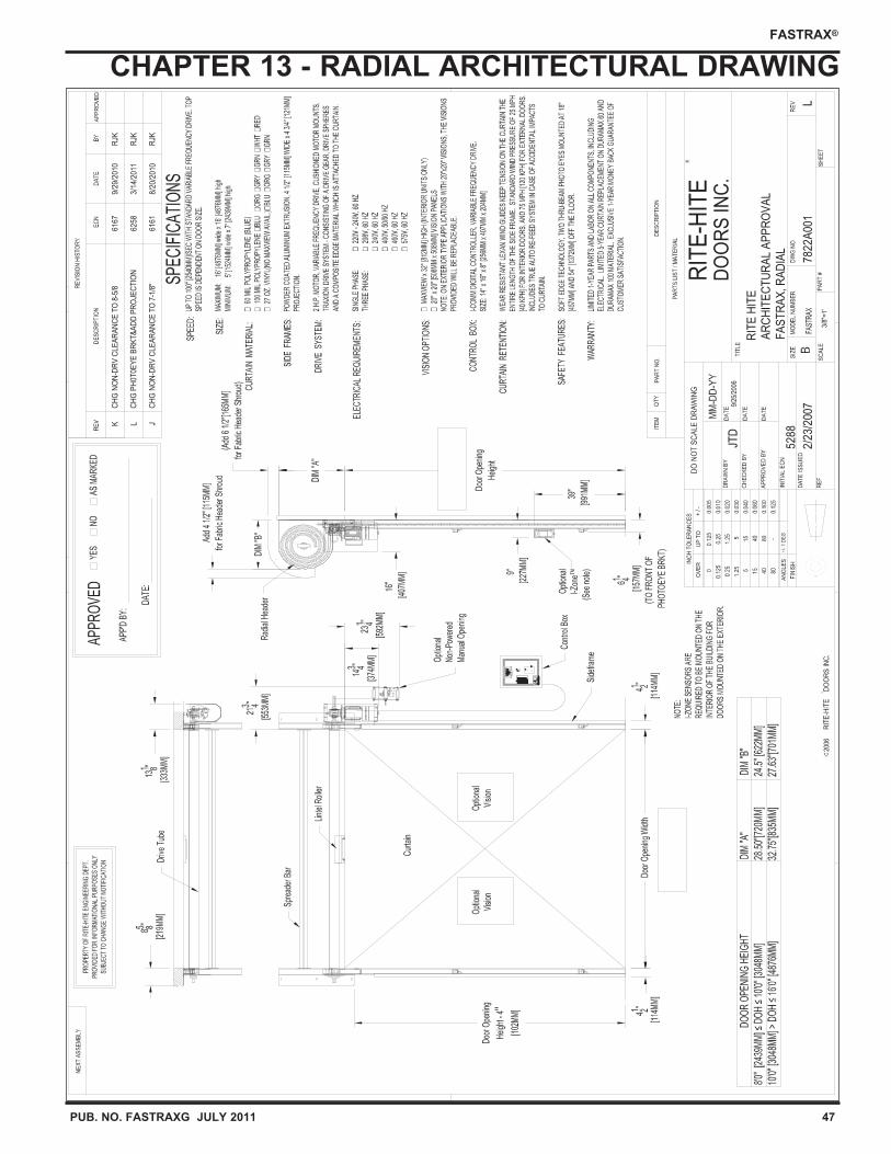
PUB. NO. FASTRAXG JULY 2011 47
FASTRAX®
CHAPTER 13 - RADIAL ARCHITECTURAL DRAWING
78
22
A00
1
RIT
E-H
ITE
DO
OR
S IN
C.
3/8"
=1'
L
RIT
E H
ITE
AR
CH
ITE
CT
UR
AL
AP
PR
OV
AL
FA
ST
RA
X, R
AD
IAL
JTD
9/25
/200
6
52
88
2/2
3/2
007
2006
KC
HG
NO
N-D
RV
CL
EA
RA
NC
E T
O 8
-5/8
61
67
9/2
9/2
010
RJK
LC
HG
PH
0T
0E
YE
BR
KT
&A
DD
PR
OJE
CT
ION
62
58
3/1
4/2
011
RJK
JC
HG
NO
N-D
RV
CL
EA
RA
NC
E T
O 7
-1/8
"6
16
18
/20
/20
10R
JK
DO
OR
SYST
EM
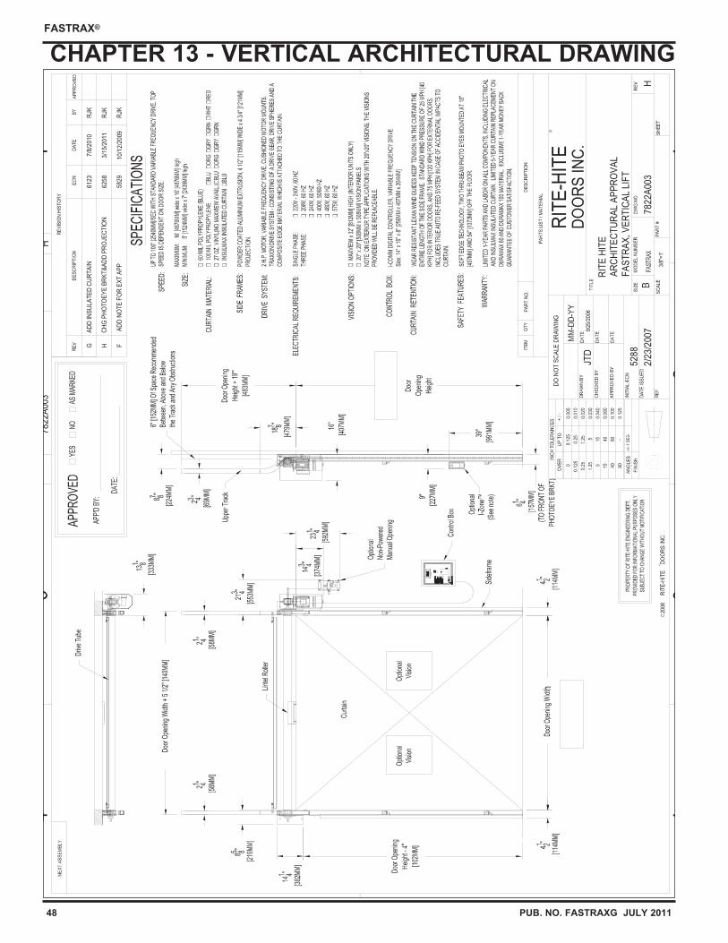
48 PUB. NO. FASTRAXG JULY 2011
FASTRAX®
CHAPTER 13 - VERTICAL ARCHITECTURAL DRAWING
78
22
A00
3
78
22
A00
3
RIT
E-H
ITE
DO
OR
S IN
C.
3/8"
=1'
H
H
RIT
E H
ITE
AR
CH
ITE
CT
UR
AL
AP
PR
OV
AL
FA
ST
RA
X, V
ER
TIC
AL
LIF
T
JTD
9/25
/200
6
52
88
2/2
3/2
007
2006
GA
DD
INS
UL
AT
ED
CU
RT
AIN
61
23
7/8
/20
10R
JK
HC
HG
PH
OT
OE
YE
BR
KT
&A
DD
PR
OJE
CT
ION
62
58
3/1
5/2
011
RJK
F A
DD
NO
TE
FO
R E
XT
AP
P5
82
91
0/1
2/2
009
RJK
DO
OR
SYST
EM
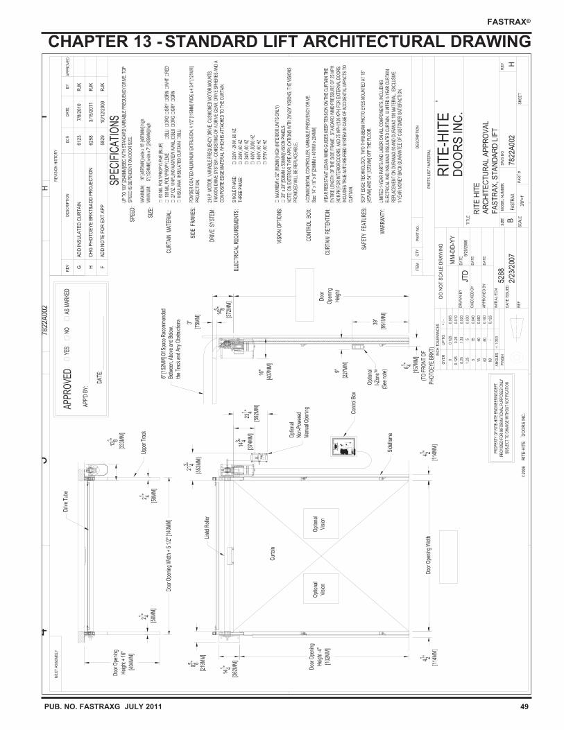
PUB. NO. FASTRAXG JULY 2011 49
FASTRAX®
CHAPTER 13 -STANDARD LIFT ARCHITECTURAL DRAWING
78
22
A00
2
78
22
A00
2
RIT
E-H
ITE
DO
OR
S IN
C.
3/8"
=1'
H
H
RIT
E H
ITE
AR
CH
ITE
CT
UR
AL
AP
PR
OV
AL
FA
ST
RA
X, S
TA
ND
AR
D L
IFT
JTD
9/25
/200
6
52
88
2/2
3/2
007
2006
GA
DD
INS
ULA
TE
D C
UR
TA
IN6
12
37
/8/2
010
RJK
HC
HG
PH
OT
OE
YE
BR
KT
&A
DD
PR
OJE
CT
ION
62
58
3/1
5/2
011
RJK
FA
DD
NO
TE
FO
R E
XT
AP
P5
82
91
0/1
2/2
009
RJK
DO
OR
SYST
EM
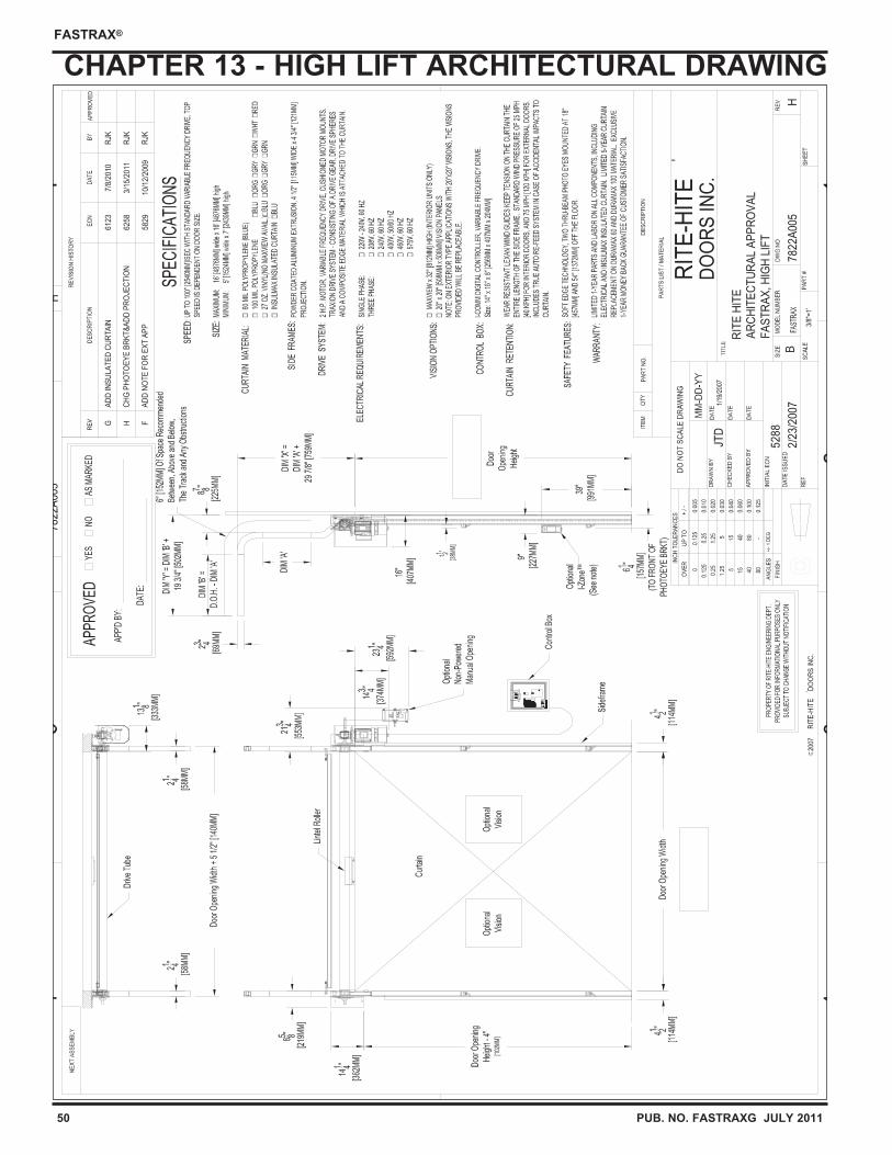
50 PUB. NO. FASTRAXG JULY 2011
FASTRAX®
CHAPTER 13 - HIGH LIFT ARCHITECTURAL DRAWING
DO
OR
SYST
EM
78
22
A00
5
78
22
A00
5
RIT
E-H
ITE
DO
OR
S IN
C.
3/8"
=1'
H
H
RIT
E H
ITE
AR
CH
ITE
CT
UR
AL
AP
PR
OV
AL
FA
ST
RA
X, H
IGH
LIF
T
JTD
1/19
/200
7
52
88
2/2
3/2
007
2007
GA
DD
INS
UL
AT
ED
CU
RT
AIN
61
23
7/8
/20
10R
JK
HC
HG
PH
OT
OE
YE
BR
KT
&A
DD
PR
OJE
CT
ION
62
58
3/1
5/2
011
RJK
FA
DD
NO
TE
FO
R E
XT
AP
P5
82
91
0/1
2/2
009
RJK
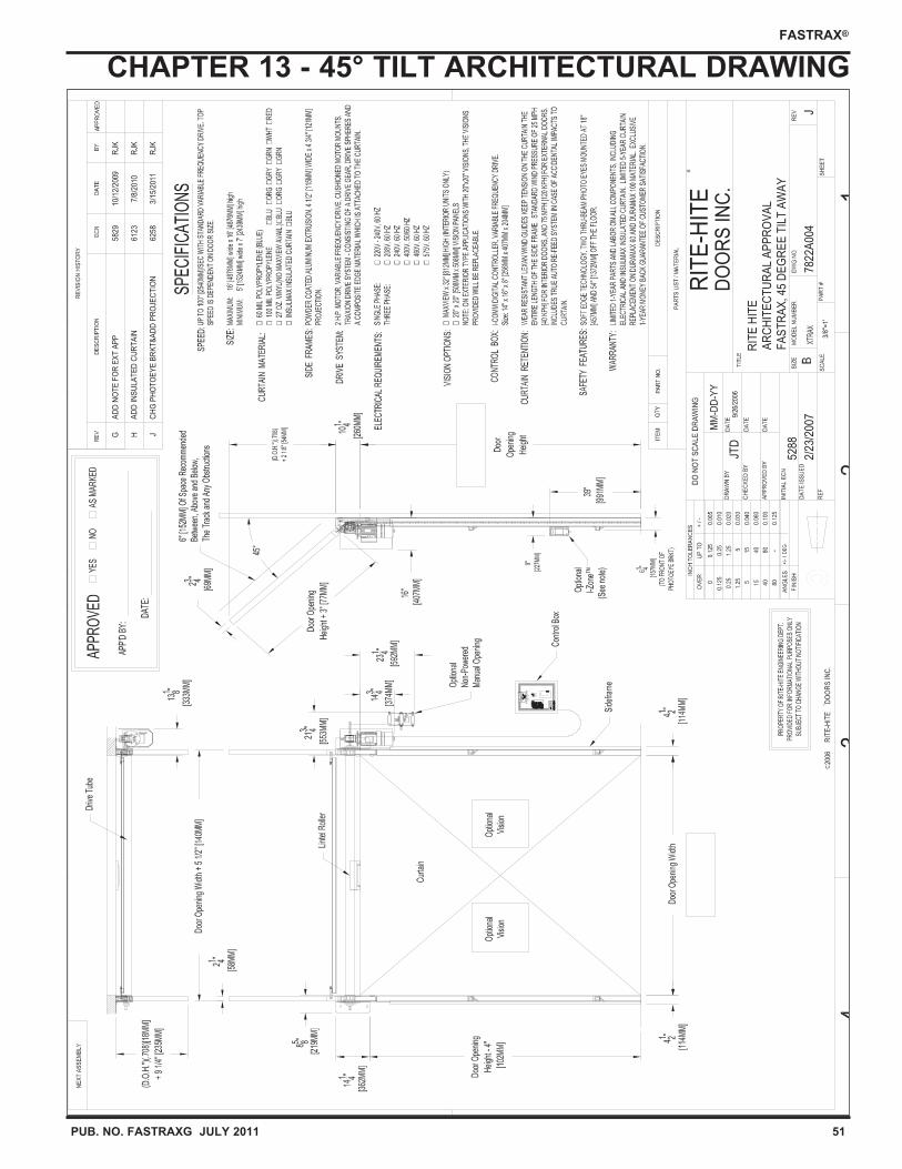
PUB. NO. FASTRAXG JULY 2011 51
FASTRAX®
CHAPTER 13 - 45° TILT ARCHITECTURAL DRAWING
7822
A00
4
RIT
E-H
ITE
DO
OR
S IN
C.
3/8"
=1'
J
RIT
E H
ITE
AR
CH
ITE
CT
UR
AL
AP
PR
OV
AL
FA
ST
RA
X, 4
5 D
EG
RE
E T
ILT
AW
AY
JTD
9/26
/200
6
5288
2/23
/200
7
2006
GA
DD
NO
TE
FO
R E
XT
AP
P5
82
91
0/1
2/2
009
RJK
HA
DD
INS
UL
AT
ED
CU
RT
AIN
61
23
7/8
/201
0R
JK
JC
HG
PH
OT
OE
YE
BR
KT
&A
DD
PR
OJE
CT
ION
62
58
3/1
5/2
011
RJK
DO
OR
SY
STEM
52 PUB. NO. FASTRAXG JULY 2011
FASTRAX®
WARRANTY
RITE-HITE DOORS, INC. warrants that its FasTrax door will operate or perform in conformance
with the published specifications when subjected to normal, proper and intended usage and be
free from defects in material and workmanship for a period of one (1) year from the date of
shipment.
RITE-HITE DOORS, INC. warrants that the FasTrax 60 and 100 mil curtain fabric integrity only,
shall be free from material defects for a period of five (5) years.
The curtain fabric warranty covers material failure under normal wear conditions.
It does not cover seals, spheres, edging or damage incurred from abuse, misuse, impact,
accidents or disaster. It does not cover 27oz material, vision wear or labor.
Fuses, bulbs, power failures or electrical power surges are items that are not considered warranty.
All claims for breach of this warranty must be made within thirty (30) days after the defect is or
can, with reasonable care, be discovered to be entitled to the benefits of this warranty, the
products must have been properly installed, maintained, operated within their rated capacities, and
not otherwise abused.
Periodic lubrication and adjustment is the sole responsibility of the end user.
This warranty is RITE-HITE DOORS, INC. exclusive warranty. RITE-HITE DOORS, INC. expressly
disclaims all implied warranties including the implied warranties of merchantability and fitness.
Non-standard RITE-HITE DOORS, INC. warranties, if any, must be specified by RITE-HITE
DOORS, INC. in writing.
In the event of any defects covered by this warranty, RITE-HITE DOORS, INC. will remedy such
defects by repairing or replacing any defective equipment or parts, bearing all of the costs for
parts, labor, and transportation based on the warranty policy.
This shall be the exclusive remedy for all claims whether based on contract negligence or strict
liability. Neither RITE-HITE DOORS, INC. any other manufacturer whose products are the subject
of this transaction, nor any RITE-HITE DOORS, INC. representative, shall in any event be liable
for any loss or use of any equipment or incidental or consequential damages of any kind whether
for breach of warranty, negligence, or strict liability. The application of a manufacturer's
specifications to a particular job is the responsibility of the purchaser. RITE-HITE DOORS, INC.
sole obligation with respect to its product shall be to repair or (at our own discretion) replace the
product.
RITE-HITE DOORS INC
8900 N. Arbon Drive
P.O. Box 245020
Milwaukee, Wisconsin 53224-9520
Sales: 414-355-2600
Toll Free: 800-456-0600
Aftermarket: 563-589-2781
Service: 563-589-2722
Service Fax: 563-589-2737
Representatives in All Major Cities
www.ritehite.com