vehicle restraint owner’s manual - rite-hite
TRANSCRIPT
VBR-600 Dok-Lok®
Vehicle RestraintOwner’s Manual
This Manual Covers Restraints Built After Serial Numbers:4634330001 and up
PRINTED IN U.S.A.RITE-HITE PRINT SHOP
PUBLICATION NO. 1328JANUARY 2016
MADE IN U.S.A.
2 Pub. No. 1328 — January 2016
RITE-HITE® VBR-600 DOK-LOK® Owner’s Manual
Pub. No. 1328 — January 2016 3
RITE-HITE® VBR-600 DOK-LOK® Owner’s Manual
INTRODUCTION . . . . . . . . . . . . . . . . . . . . . . . . . . . . . . . . . . . . . . . . . . . . . . . . . . . . . . . . . . . . . . . . . . . . . . . . . . . . . . . . . . . . . . . . . . . . . . . 3
SAFETY WARNINGS . . . . . . . . . . . . . . . . . . . . . . . . . . . . . . . . . . . . . . . . . . . . . . . . . . . . . . . . . . . . . . . . . . . . . . . . . . . . . . . . . . . . . . . . . . . . . 4
FCC COMPLIANCE . . . . . . . . . . . . . . . . . . . . . . . . . . . . . . . . . . . . . . . . . . . . . . . . . . . . . . . . . . . . . . . . . . . . . . . . . . . . . . . . . . . . . . . . . . . . . . . . 5
OWNERS RESPONSIBILITY . . . . . . . . . . . . . . . . . . . . . . . . . . . . . . . . . . . . . . . . . . . . . . . . . . . . . . . . . . . . . . . . . . . . . . . . . . . . . . . . . . . . . . . 6
DEFINITION AND FUNCTION . . . . . . . . . . . . . . . . . . . . . . . . . . . . . . . . . . . . . . . . . . . . . . . . . . . . . . . . . . . . . . . . . . . . . . . . . . . . . . . . . . . . . . . 7
FEATURES . . . . . . . . . . . . . . . . . . . . . . . . . . . . . . . . . . . . . . . . . . . . . . . . . . . . . . . . . . . . . . . . . . . . . . . . . . . . . . . . . . . . . . . . . . . . . . . . . . . . . 8
OPERATING PROCEDURE . . . . . . . . . . . . . . . . . . . . . . . . . . . . . . . . . . . . . . . . . . . . . . . . . . . . . . . . . . . . . . . . . . . . . . . . . . . . . . . . . . . . . . . . 10
MAINTENANCE . . . . . . . . . . . . . . . . . . . . . . . . . . . . . . . . . . . . . . . . . . . . . . . . . . . . . . . . . . . . . . . . . . . . . . . . . . . . . . . . . . . . . . . . . . . . . . . . . . 14
TROUBLESHOOTING . . . . . . . . . . . . . . . . . . . . . . . . . . . . . . . . . . . . . . . . . . . . . . . . . . . . . . . . . . . . . . . . . . . . . . . . . . . . . . . . . . . . . . . . . . . . 15
REPLACEMENT PARTS. . . . . . . . . . . . . . . . . . . . . . . . . . . . . . . . . . . . . . . . . . . . . . . . . . . . . . . . . . . . . . . . . . . . . . . . . . . . . . . . . . . . . . . . . . . . 25
WARRANTY . . . . . . . . . . . . . . . . . . . . . . . . . . . . . . . . . . . . . . . . . . . . . . . . . . . . . . . . . . . . . . . . . . . . . . . . . . . . . . . . . . . . . . . . . . . BACK COVER
INTRODUCTIONRead and understand this manual before attempting to install or operate any DOK-LOK vehicle restraint. For best results, have this productserviced by your authorized Rite-Hite® representative. The VBR-600 DOK-LOK vehicle restraint by Rite-Hite® is intended to provide a saferworkplace for workers in shipping and receiving dock areas. The VBR-600 DOK-LOK vehicle restraint is a hydraulic restraint device that, whenproperly installed and operated, retains a secure connection between the truck and dock. Signal lights and signs provide instructions to the truckdriver and DOK-LOK vehicle restraint operator that a safe condition exists. The DOK-LOK vehicle restriant is operated by pressing push buttonson an inside control panel.
TABLE OF CONTENTS
PRODUCT SPECIFIC WARRANTYRite-Hite® warrants the VBR-600 DOK-LOK vehicle restraint for two-years parts and labor from date of shipment in accordance with Rite-Hite's Standard Warranty Policy.
NOTICE TO USERYour local Rite-Hite® representative provides a Planned Maintenance Program (P.M.P.) which can be fitted to your specific operation. Callyour local representative or Rite-Hite® at 414-355-2600.
The Rite-Hite products in this manual are covered by one or more of the following U.S. patents: 5882167, 6065172, 6070283, 6085375,6092970, 6106212, 6116839, 6190109, 6276016, 6311352, 6318947, 6322310, 6360394, 6368043, 6431819, 6488464, 6524053, 6726432,6773221, 6832403, 6880301, 7032267, 7062814, 7213285, 7216391, 7363670, 7380305, 7503089, 7533431, 7546655, 7584517, 7681271,7823239, 7841823, 7877831, 7914042, 8006811, 8065770, 8141189, 8191194, 8286757, 8287223, 8303235, 8307956, 8443474, 8464384,8464846, 8465245, 8497761, 8499897, 8544130, 8547234, 8590087, 8590673, 8616826, 8657551, 8662535, 8678736, 8690087, 8905198,9010501, 9096170, 9096397, 9126775, 9139384, 9145273, 9150367, 9174811, 9227799, 9230419 and pending U.S and foreign patent applications. RITE-HITE®, THINMANTM, SAFE-T-LIP®, HYDRACHEK®, WHEEL-LOKTM, DOK-LOK®, DUAL-DOK®, SAFE-T-STRUTTM, DOK-COMMANDER®, JUMBOTM, HYDRA-RITETM, SAFE-T-GATE®, RITE-VUTM LIGHT COMMUNICATION SYSTEM and SMOOTH TRANSITIONDOK SYSTEMTM, are trademarks of Rite-Hite®.
4 Pub. No. 1328 — January 2016
RITE-HITE® VBR-600 DOK-LOK® Owner’s Manual
SAFETY WARNINGS
DO NOTOPERATE
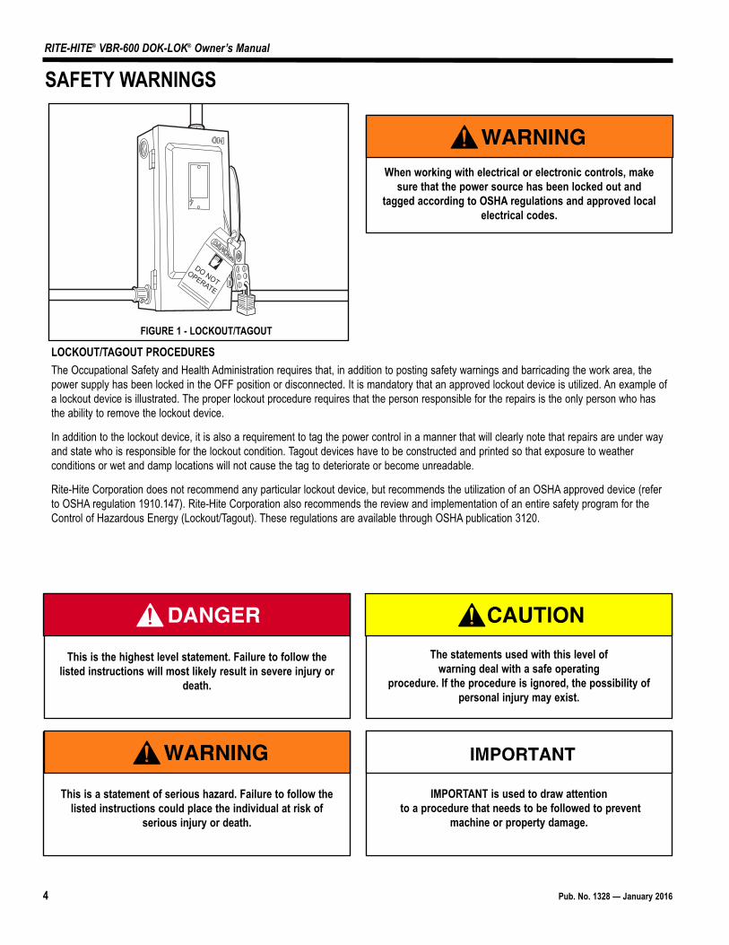
LOCKOUT/TAGOUT PROCEDURESThe Occupational Safety and Health Administration requires that, in addition to posting safety warnings and barricading the work area, thepower supply has been locked in the OFF position or disconnected. It is mandatory that an approved lockout device is utilized. An example ofa lockout device is illustrated. The proper lockout procedure requires that the person responsible for the repairs is the only person who hasthe ability to remove the lockout device.
In addition to the lockout device, it is also a requirement to tag the power control in a manner that will clearly note that repairs are under wayand state who is responsible for the lockout condition. Tagout devices have to be constructed and printed so that exposure to weatherconditions or wet and damp locations will not cause the tag to deteriorate or become unreadable.
Rite-Hite Corporation does not recommend any particular lockout device, but recommends the utilization of an OSHA approved device (referto OSHA regulation 1910.147). Rite-Hite Corporation also recommends the review and implementation of an entire safety program for theControl of Hazardous Energy (Lockout/Tagout). These regulations are available through OSHA publication 3120.
This is the highest level statement. Failure to follow thelisted instructions will most likely result in severe injury or
death.
IMPORTANT is used to draw attentionto a procedure that needs to be followed to prevent
machine or property damage.
When working with electrical or electronic controls, makesure that the power source has been locked out and
tagged according to OSHA regulations and approved localelectrical codes.
This is a statement of serious hazard. Failure to follow thelisted instructions could place the individual at risk of
serious injury or death.
The statements used with this level of warning deal with a safe operating
procedure. If the procedure is ignored, the possibility ofpersonal injury may exist.
FIGURE 1 - LOCKOUT/TAGOUT
FCC COMPLIANCE
NOTE:This equipment has been tested and found to comply with the limitsfor a Class A digital device, pursuant to Part 15 of the FCC Rules.These limits are designed to provide reasonable protection againstharmful interference when the equipment is operated in a commercialenvironment. This equipment generates, uses , and can radiate radiofrequency energy and, if not installed and used in accordance with theinstruction manual, may cause harmful interference to radiocommunications. Operation of this equipment in a residential area islikely to cause harmful interference in which case the user will berequired to correct the interference at his or her own expense.
NOTE:Changes or modifications not expressly approved by the partyresponsible for compliance could void the user’s authority to operatethe equipment.
This device complies with Part 15 of the FCC Rules. Operation issubject to the following to conditions: (1) This device may not causeharmful interference, and (2) this device must accept any interferencereceived, including interference that may cause undesirable operation.
Pub. No. 1328 — January 2016 5
RITE-HITE® VBR-600 DOK-LOK® Owner’s Manual
FCC COMPLIANCE
6 Pub. No. 1328 — January 2016
RITE-HITE® VBR-600 DOK-LOK® Owner’s Manual
OWNER RESPONSIBILITY1. The owner should recognize the inherent danger of the
interface between dock and transport vehicle. The ownershould, therefore, train and instruct operators in the safe useof dock equipment in accordance with the information providedbelow. The manufacturer shall publish, provide to the initialpurchaser, and make the following information readily availableto owners:
• Installation instructions
• Recommended initial and periodic inspections procedures
• Maintenance procedures
• Operating instructions
• Descriptions or specifications for replaceable or repairableparts
• Tables identifying the grade (slope) for all variations oflength or configuration of the dock equipment, and
• Information identifying the maximum uncontrolled dropencountered upon sudden removal of support while withinthe working range of the equipment.
It shall be the responsibility of the owner to verify that thematerial listed in this section has been received and that it ismade available for the instruction and training of presonnelentrusted with the use or maintenance of the dock equipment.
2. When a transport vehicle is parked at a loading dock, it isimportant that the vehicle is relatively perpendicular to thedock face and in close contact with at least one of the dockbumpers.
3. Nameplates, cautions, instructions, and posted warnings shallnot be obscured from the view of operating or maintenancepersonnel for whom such warnings are intended.
4. Manufacturer’s recommended periodic maintenance andinspection procedures in effect at date of shipment shall befollowed, and written records of the performance of theseprocedures should be kept.
5. As with any piece of machinery, dock equipment requires routinemaintenance, lubrication, and adjustments. Your local RITE-HITE® representative offers owners the option of aPlanned Maintenance Program (P.M.P.). As part of this service,your local RITE-HITE® representative will do all routinemaintenance, lubrication, and adjustments.
6. Dock equipment that is structurally damaged shall be removedfrom service, inspected by a manufacturer’s authorizedrepresentative, and repaired as needed before being placedback in service.
7. The manufacturer shall make available replacementnameplates, caution/instruction labels, andoperating/maintenance manuals upon request of the owner.The owner shall see that all nameplates, caution/instructionmarkings or labels are in place and legible, and that theappropriate operating/maintenance manuals are provided tousers.
8. Modifications or alterations of dock equipment shall be madeonly with written permission of the original manufacturer.These changes shall also satisfy all safety recommendationsof the original equipment manufacturer for the particularapplication of the dock equipment.
9. In order to be entitled to the benefits of the standard productwarranty, the dock equipment must have been properlyinstalled, maintained and operated within its rated capacitiesand/or specific design parameters, and not otherwise abused.
10. It is recommended that trailers equipped with air ridesuspensions should remove the air from the suspension tominimize trailer bed drop, prior to loading or unloading.
11. When industrial trucks are driven on and off transport vehiclesduring the loading and unloading operation, the brakes on thetransport vehicle shall be applied and wheel chocks or apositive restraining device shall be engaged.
12. In selecting dock equipment, it is important to consider notonly present requirements but also future plans or adverseenvironments.

Pub. No. 1328 — January 2016 7
RITE-HITE® VBR-600 DOK-LOK® Owner’s Manual
DEFINITION AND FUNCTIONThe VBR-600 DOK-LOK vehicle restraint is a hydraulic, pit storedrestraint device used to secure trucks and semi-trailers with an intactRear Impact Guard (R.I.G.) to the face of a loading dock. This isachieved by securing the R.I.G. with a steel barrier. This preventsforward movement of the truck/trailer that may create an unsafe voidbetween the face of the dock and the rear end of the truck/trailer asa forklift travels from the loading dock onto the trailer; or to create anobstruction noticeable to the truck driver, should the driveraccidentally try to pull the truck/trailer away while it is being serviced.
The proper or improper activation of the barrier is monitored by:
• VISUAL CONTROL— One set of flashing green or red lights located at the insideof the building for the forklift operator, and one set locatedoutside of the building for the truck driver. In addition to thelights, there are three instruction signs.
• AUDIO CONTROL— A horn will sound at the inside of the building, warning theforklift operator if there is not R.I.G. present, or if theengagement is improper. In this case, the trailer must besecured by other means (wheel chokes, etc.) prior to servicingtrailer.
Prerequisite for proper barrier engagement is that the trailer isparked firmly against a 4" (trade standard) thick dock bumper. Theactivation/deactivation is solely controlled from inside of the buildingby momentarily depressing either the Lock (raise) button or theUnlock (lower) button.
The normal mode of the barrier is in the lower STOREDposition, showing a flashing red light (trailer not secured) at theinside of the building and a flashing green light (trailer free to moveto or away from the loading dock) at the outside of the building.
Once the trailer is parked, the dock attendant will depress the Lockbutton. This will raise the barrier to engage the R.I.G. As soon as theR.I.G. is properly locked, there will be a simultaneous light change -the inside will change from red to green flashing (trailer secured) andthe outside will change from green to red flashing (do not movetrailer). After the service is complete, the dock attendant will have todepress the Unlock button which then will return the barrier to itsSTORED position.
A proper barrier engagement is achieved when the barrier raisesunobstructed to secure the horizontal cross member of the R.I.G.Assembly. An improper barrier engagement is if the horizontal crossmember of the R.I.G. is missing, obstructed or it is bent or locatedso far toward the rear axle of the trailer that it will prevent the freepassage of the barrier. At this point, the trailer must be secured byother means (example: wheel chocks) in order to becomeserviceable.
8 Pub. No. 1328 — January 2016
RITE-HITE® VBR-600 DOK-LOK® Owner’s Manual
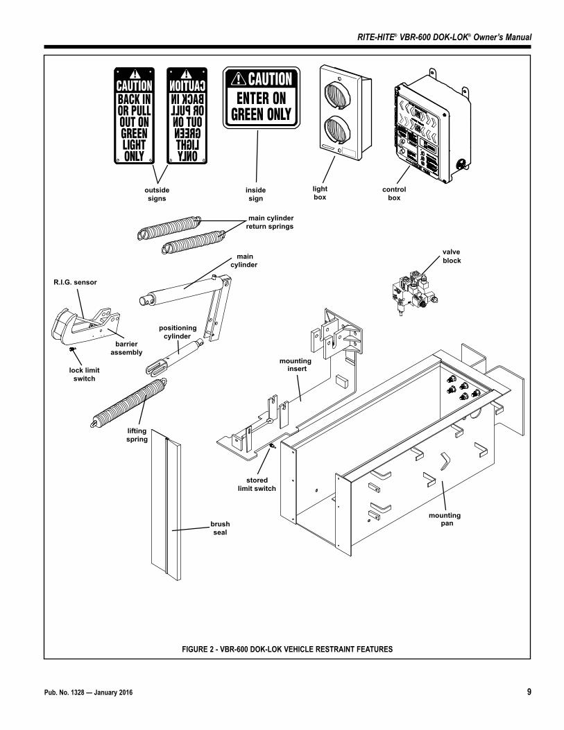
Refer to Figure 2, page 8 for the locations of the following features:
R.I.G.Acronym used for the Federally mandated rear impactguard located on the rear of over the road trailers toprevent accidental underride by automobiles.
POSITIONING CYLINDER/LIFTING SPRINGPositioning Cylinder extends to lower main cylinder/barrier assemblyto stored state. Lifting Spring, raises locking cylinder/barrierassembly to capture R.I.G. and keep in constant contact.
MAIN CYLINDER / RETURN SPRINGSMain Cylinder extends to position barrier outside of pit. Returnsprings retract the main cylinder, keeping the vertical barrier face incontact with the R.I.G.
R.I.G. SENSOR / LOCK LIMIT SWITCHDetects when the barrier is secured to the R.I.G.
BARRIER ASSEMBLYSecures R.I.G. to prevent trailer from separating from the dock.
STORED LIMIT SWITCHSenses the barrier assembly is in the proper stored position.
HYDRAULIC VALVE BLOCKAllows restraint to operate using the leveler power unit.
PIT COVER/BRUSH SEALProtects the barrier assembly, float mechanism, hydraulic hoses andcylinders from debris.
CONTROL BOX, OUTSIDE LIGHT BOX AND SIGNAGECombination of these components is used to control the VBR-600DOK-LOK vehicle restraint and provide audio/visual communicationsto the dock attendant and trailer driver.
MOUNTING INSERTVBR6 is assembled to this and installed into mounting pan. May shiptogether with mounting pan or seperately.
MOUNTING PANForms VBR6 pit. Placed in leveler pit and building wall. Prior topouring concrete pit floor, VBR6 is installed in mounting pan by wayof the mounting insert. May ship together with mounting insert orearlier. To be poured in to building prior to VBR6 shipment.
FEATURES
Pub. No. 1328 — January 2016 9
RITE-HITE® VBR-600 DOK-LOK® Owner’s Manual
outsidesigns
insidesign
lightbox
controlbox
main cylinderreturn springs
maincylinder
R.I.G. sensor
lock limitswitch
barrierassembly
liftingspring
positioningcylinder
brushseal
storedlimit switch
mountingpan
valveblock
mountinginsert
FIGURE 2 - VBR-600 DOK-LOK VEHICLE RESTRAINT FEATURES
10 Pub. No. 1328 — January 2016
RITE-HITE® VBR-600 DOK-LOK® Owner’s Manual
OPERATING PROCEDURE
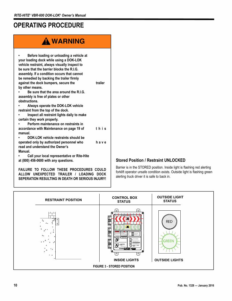
Stored Position / Restraint UNLOCKEDBarrier is in the STORED position. Inside light is flashing red alertingforklift operator unsafe condition exists. Outside light is flashing greenalerting truck driver it is safe to back in.
OUTSIDE LIGHTSTATUS
CONTROL BOXSTATUSRESTRAINT POSITION
RED
GREEN
INSIDE LIGHTS OUTSIDE LIGHTS
OUTSIDE LIGHTSCheck outside lights whenboth LEDs are off.
UNLOCK
LOCK
1
3
2
HORN OVERRIDEDOK-LOK®
DO NOT ENTER TRAILER
ENTER TRAILER
Visually inspect before loading/unloading vehicle. DOK-LOK hook must secure rear impact guard. See warnings on side panel.
Additional warning labels, manuals and other information
are available by calling:1-800-456-0600
If red light is on and/or horn sounds, DOK-LOK is not properly engaged.
Check operation of DOK-LOK.
Vehicle may not be against dock.
R.I.G. may not be compatible.
Hook travel may be obstructed.
Before using "HORN OVERRIDE," secure vehicle by other means.
Reset system by engaging "HORN OVERRIDE" control again. Then repeat "UNLOCK" operation.
When in "HORN OVERRIDE" mode:Both red and green Lights flash. "LOCK" and "UNLOCK" controls are not functional.
Horn can be silenced by engaging "HORN OVERRIDE" control.
Before using "HORN OVERRIDE," secure vehicle by other means prior to entering.
If horn and red light are on after "UNLOCK" control is pressed, hook may be held by R.I.G.
To release hook: Back trailer up against dock. Repeat "UNLOCK" operation.
FIGURE 3 - STORED POSITION
• Before loading or unloading a vehicle at your loading dock while using a DOK-LOK vehicle restraint, always visually inspect to be sure that the barrier blocks the R.I.G. assembly. If a condition occurs that cannot be remedied by backing the trailer firmly against the dock bumpers, secure the trailer by other means.• Be sure that the area around the R.I.G. assembly is free of plates or other obstructions.• Always operate the DOK-LOK vehicle restraint from the top of the dock.• Inspect all restraint lights daily to make certain they work properly.• Perform maintenance on restraints in accordance with Maintenance on page 19 of t h i smanual.• DOK-LOK vehicle restraints should be operated only by authorized personnel who h a v eread and understand the Owner’s Manual.• Call your local representative or Rite-Hite at (800) 456-0600 with any questions.
FAILURE TO FOLLOW THESE PROCEDURES COULDALLOW UNEXPECTED TRAILER / LOADING DOCKSEPERATION RESULTING IN DEATH OR SERIOUS INJURY!

Pub. No. 1328 — January 2016 11
RITE-HITE® VBR-600 DOK-LOK® Owner’s Manual
Restraint LOCKEDOnce the R.I.G. is obstructed by the barrier, a LOCKEDcondition exists. Inside light is flashing green alerting the forkliftoperator a safe condition exists. Outside light is flashing red alertingtruck driver not to move.
OUTSIDE LIGHTSTATUS
CONTROL BOXSTATUSRESTRAINT POSITION
OUTSIDE LIGHTSINSIDE LIGHTS
GREEN
RED
OUTSIDE LIGHTSCheck outside lights whenboth LEDs are off.
UNLOCK
LOCK
1
3
2
HORN OVERRIDEDOK-LOK®
DO NOT ENTER TRAILER
ENTER TRAILER
Visually inspect before loading/unloading vehicle. DOK-LOK hook must secure rear impact guard. See warnings on side panel.
Additional warning labels, manuals and other information
are available by calling:1-800-456-0600
If red light is on and/or horn sounds, DOK-LOK is not properly engaged.
Check operation of DOK-LOK.
Vehicle may not be against dock.
R.I.G. may not be compatible.
Hook travel may be obstructed.
Before using "HORN OVERRIDE," secure vehicle by other means.
Reset system by engaging "HORN OVERRIDE" control again. Then repeat "UNLOCK" operation.
When in "HORN OVERRIDE" mode:Both red and green Lights flash. "LOCK" and "UNLOCK" controls are not functional.
Horn can be silenced by engaging "HORN OVERRIDE" control.
Before using "HORN OVERRIDE," secure vehicle by other means prior to entering.
If horn and red light are on after "UNLOCK" control is pressed, hook may be held by R.I.G.
To release hook: Back trailer up against dock. Repeat "UNLOCK" operation.
FIGURE 4 - RESTRAINT LOCKING
OUTSIDE LIGHTSTATUS
CONTROL BOXSTATUSRESTRAINT POSITION
OUTSIDE LIGHTSINSIDE LIGHTS
GREEN
RED
OUTSIDE LIGHTSCheck outside lights whenboth LEDs are off.
UNLOCK
LOCK
1
3
2
HORN OVERRIDEDOK-LOK®
DO NOT ENTER TRAILER
ENTER TRAILER
Visually inspect before loading/unloading vehicle. DOK-LOK hook must secure rear impact guard. See warnings on side panel.
Additional warning labels, manuals and other information
are available by calling:1-800-456-0600
If red light is on and/or horn sounds, DOK-LOK is not properly engaged.
Check operation of DOK-LOK.
Vehicle may not be against dock.
R.I.G. may not be compatible.
Hook travel may be obstructed.
Before using "HORN OVERRIDE," secure vehicle by other means.
Reset system by engaging "HORN OVERRIDE" control again. Then repeat "UNLOCK" operation.
When in "HORN OVERRIDE" mode:Both red and green Lights flash. "LOCK" and "UNLOCK" controls are not functional.
Horn can be silenced by engaging "HORN OVERRIDE" control.
Before using "HORN OVERRIDE," secure vehicle by other means prior to entering.
If horn and red light are on after "UNLOCK" control is pressed, hook may be held by R.I.G.
To release hook: Back trailer up against dock. Repeat "UNLOCK" operation.
FIGURE 5 - RESTRAINT LOCKED
Visually inspect to ensure that the DOK-LOK barrierobstructs the R.I.G. of the trailer being serviced beforeoperating the dock leveler.
Restraint Locking, LOCK Button PressedTrailer has backed into loading dock and is parked firmly againstdock bumpers. Barrier extends out of the pit from stored positionand moves up to obstruct R.I.G. Inside light is steady red alertingthe operator that an unsafe condition exists and barrier is in transit.Outside light is flashing red alerting truck driver not to move.
If horn sounds, go to FAULT state, otherwise go to RestraintLOCKED.
If trailer can not be restrainted due to a lift gate or otherobstruction that could become damaged, go to OVERRIDE
state.
12 Pub. No. 1328 — January 2016
RITE-HITE® VBR-600 DOK-LOK® Owner’s Manual
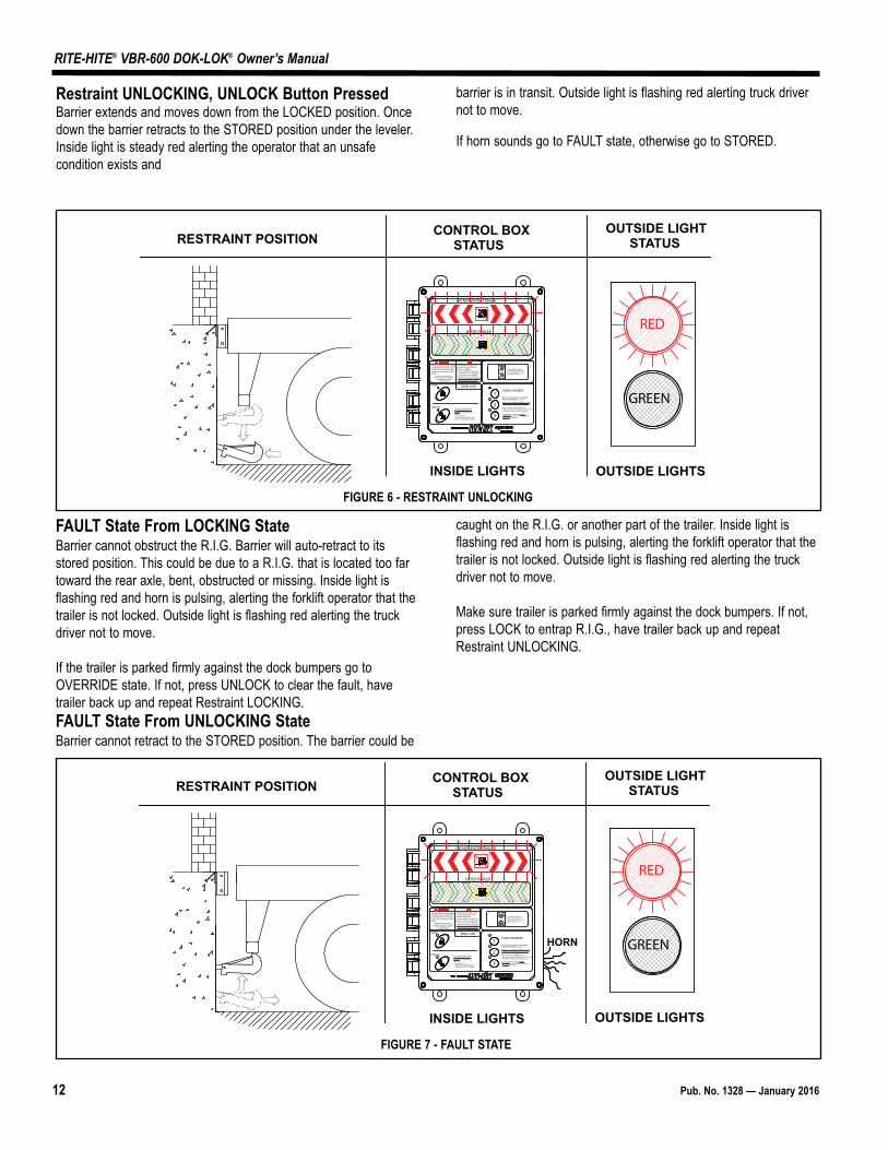
Restraint UNLOCKING, UNLOCK Button PressedBarrier extends and moves down from the LOCKED position. Oncedown the barrier retracts to the STORED position under the leveler.Inside light is steady red alerting the operator that an unsafecondition exists and
barrier is in transit. Outside light is flashing red alerting truck drivernot to move.
If horn sounds go to FAULT state, otherwise go to STORED.
FAULT State From LOCKING StateBarrier cannot obstruct the R.I.G. Barrier will auto-retract to itsstored position. This could be due to a R.I.G. that is located too fartoward the rear axle, bent, obstructed or missing. Inside light isflashing red and horn is pulsing, alerting the forklift operator that thetrailer is not locked. Outside light is flashing red alerting the truckdriver not to move.
If the trailer is parked firmly against the dock bumpers go toOVERRIDE state. If not, press UNLOCK to clear the fault, havetrailer back up and repeat Restraint LOCKING. FAULT State From UNLOCKING StateBarrier cannot retract to the STORED position. The barrier could be
caught on the R.I.G. or another part of the trailer. Inside light isflashing red and horn is pulsing, alerting the forklift operator that thetrailer is not locked. Outside light is flashing red alerting the truckdriver not to move.
Make sure trailer is parked firmly against the dock bumpers. If not,press LOCK to entrap R.I.G., have trailer back up and repeatRestraint UNLOCKING.
OUTSIDE LIGHTSTATUS
CONTROL BOXSTATUSRESTRAINT POSITION
RED
GREEN
INSIDE LIGHTS OUTSIDE LIGHTS
OUTSIDE LIGHTSCheck outside lights whenboth LEDs are off.
UNLOCK
LOCK
1
3
2
HORN OVERRIDEDOK-LOK®
DO NOT ENTER TRAILER
ENTER TRAILER
Visually inspect before loading/unloading vehicle. DOK-LOK hook must secure rear impact guard. See warnings on side panel.
Additional warning labels, manuals and other information
are available by calling:1-800-456-0600
If red light is on and/or horn sounds, DOK-LOK is not properly engaged.
Check operation of DOK-LOK.
Vehicle may not be against dock.
R.I.G. may not be compatible.
Hook travel may be obstructed.
Before using "HORN OVERRIDE," secure vehicle by other means.
Reset system by engaging "HORN OVERRIDE" control again. Then repeat "UNLOCK" operation.
When in "HORN OVERRIDE" mode:Both red and green Lights flash. "LOCK" and "UNLOCK" controls are not functional.
Horn can be silenced by engaging "HORN OVERRIDE" control.
Before using "HORN OVERRIDE," secure vehicle by other means prior to entering.
If horn and red light are on after "UNLOCK" control is pressed, hook may be held by R.I.G.
To release hook: Back trailer up against dock. Repeat "UNLOCK" operation.
FIGURE 6 - RESTRAINT UNLOCKING
OUTSIDE LIGHTSTATUS
CONTROL BOXSTATUSRESTRAINT POSITION
HORN
RED
GREEN
INSIDE LIGHTS OUTSIDE LIGHTS
OUTSIDE LIGHTSCheck outside lights whenboth LEDs are off.
UNLOCK
LOCK
1
3
2
HORN OVERRIDEDOK-LOK®
DO NOT ENTER TRAILER
ENTER TRAILER
Visually inspect before loading/unloading vehicle. DOK-LOK hook must secure rear impact guard. See warnings on side panel.
Additional warning labels, manuals and other information
are available by calling:1-800-456-0600
If red light is on and/or horn sounds, DOK-LOK is not properly engaged.
Check operation of DOK-LOK.
Vehicle may not be against dock.
R.I.G. may not be compatible.
Hook travel may be obstructed.
Before using "HORN OVERRIDE," secure vehicle by other means.
Reset system by engaging "HORN OVERRIDE" control again. Then repeat "UNLOCK" operation.
When in "HORN OVERRIDE" mode:Both red and green Lights flash. "LOCK" and "UNLOCK" controls are not functional.
Horn can be silenced by engaging "HORN OVERRIDE" control.
Before using "HORN OVERRIDE," secure vehicle by other means prior to entering.
If horn and red light are on after "UNLOCK" control is pressed, hook may be held by R.I.G.
To release hook: Back trailer up against dock. Repeat "UNLOCK" operation.
FIGURE 7 - FAULT STATE
Pub. No. 1328 — January 2016 13
RITE-HITE® VBR-600 DOK-LOK® Owner’s Manual
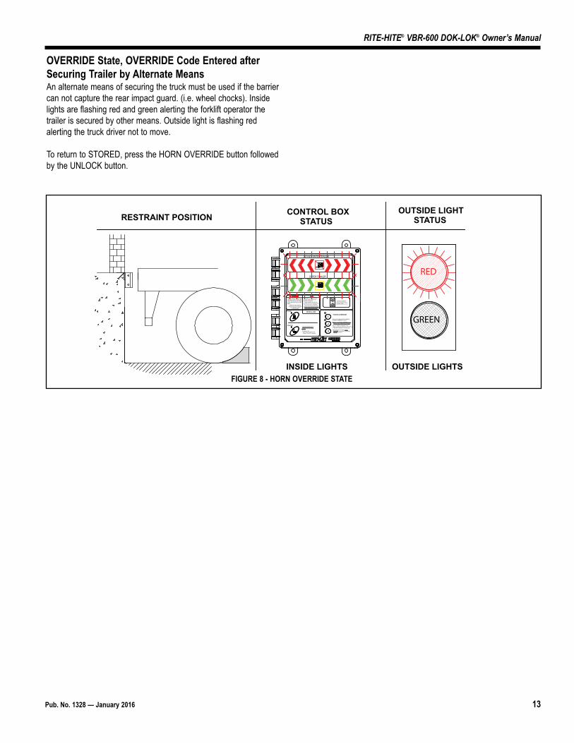
OVERRIDE State, OVERRIDE Code Entered afterSecuring Trailer by Alternate MeansAn alternate means of securing the truck must be used if the barriercan not capture the rear impact guard. (i.e. wheel chocks). Insidelights are flashing red and green alerting the forklift operator thetrailer is secured by other means. Outside light is flashing redalerting the truck driver not to move.
To return to STORED, press the HORN OVERRIDE button followedby the UNLOCK button.
OUTSIDE LIGHTSTATUS
CONTROL BOXSTATUSRESTRAINT POSITION
OUTSIDE LIGHTSINSIDE LIGHTS
RED
GREEN
OUTSIDE LIGHTSCheck outside lights whenboth LEDs are off.
UNLOCK
LOCK
1
3
2
HORN OVERRIDEDOK-LOK®
DO NOT ENTER TRAILER
ENTER TRAILER
Visually inspect before loading/unloading vehicle. DOK-LOK hook must secure rear impact guard. See warnings on side panel.
Additional warning labels, manuals and other information
are available by calling:1-800-456-0600
If red light is on and/or horn sounds, DOK-LOK is not properly engaged.
Check operation of DOK-LOK.
Vehicle may not be against dock.
R.I.G. may not be compatible.
Hook travel may be obstructed.
Before using "HORN OVERRIDE," secure vehicle by other means.
Reset system by engaging "HORN OVERRIDE" control again. Then repeat "UNLOCK" operation.
When in "HORN OVERRIDE" mode:Both red and green Lights flash. "LOCK" and "UNLOCK" controls are not functional.
Horn can be silenced by engaging "HORN OVERRIDE" control.
Before using "HORN OVERRIDE," secure vehicle by other means prior to entering.
If horn and red light are on after "UNLOCK" control is pressed, hook may be held by R.I.G.
To release hook: Back trailer up against dock. Repeat "UNLOCK" operation.
FIGURE 8 - HORN OVERRIDE STATE
14 Pub. No. 1328 — January 2016
RITE-HITE® VBR-600 DOK-LOK® Owner’s Manual
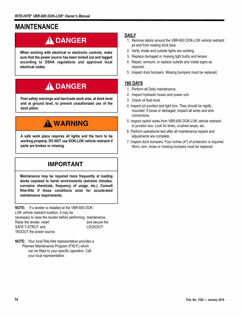
NOTE: If a leveler is installed at the VBR-600 DOK-LOK vehicle restraint location, it may be necessary to raise the leveler before performing maintenance.Raise the leveler, insert and secure theSAFE-T-STRUT, and LOCKOUT/TAGOUT the power source.
NOTE: Your local Rite-Hite representative provides a Planned Maintenance Program (P.M.P.) which
can be fitted to your specific operation. Call your local representative.
DAILY1. Remove debris around the VBR-600 DOK-LOK vehicle restraint
pit and from loading dock face.2. Verify inside and outside lights are working.3. Replace damaged or missing light bulbs and lenses.4. Repair, remount, or replace outside and inside signs as
required.5. Inspect dock bumpers. Missing bumpers must be replaced.
180 DAYS1. Perform all Daily maintenance.2. Inspect hydraulic hoses and power unit.3 Check oil fluid level.4. Inspect pit junction and light box. They should be rigidly
mounted. If loose or damaged, inspect all wires and wireconnections.
5. Inspect switch wires from VBR-600 DOK-LOK vehicle restraintto junction box. Look for kinks, crushed areas, etc.
6. Perform operational test after all maintenance repairs andadjustments are complete.
7. Inspect dock bumpers. Four inches (4") of protection is required.Worn, torn, loose or missing bumpers must be replaced.
MAINTENANCE
A safe work place requires all lights and the horn to beworking properly. DO NOT use DOK-LOK vehicle restraint ifparts are broken or missing.
When working with electrical or electronic controls, makesure that the power source has been locked out and taggedaccording to OSHA regulations and approved localelectrical codes.
Post safety warnings and barricade work area, at dock leveland at ground level, to prevent unauthorized use of thedock pition.
Maintenance may be required more frequently at loadingdocks exposed to harsh environments (extreme climates,corrosive chemicals, frequency of usage, etc.). ConsultRite-Hite if these conditions exist for acceleratedmaintenance requirements.
Pub. No. 1328 — January 2016 15
RITE-HITE® VBR-600 DOK-LOK® Owner’s Manual
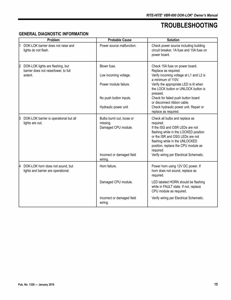
Problem Probable Cause Solution1 DOK-LOK barrier does not raise and Power source malfunction. Check power source including building
lights do not flash. circuit breaker, 1A fuse and 15A fuse onpower board.
2 DOK-LOK lights are flashing, but Blown fuse. Check 15A fuse on power board. barrier does not raise/lower, to full Replace as required.extent. Low incoming voltage. Verify incoming voltage at L1 and L2 is
a minimum of 110V. Power module failure. Verify the appropriate LED is lit when
the LOCK button or UNLOCK button ispressed.
No push button inputs. Check for failed push button board or disconnect ribbon cable.
Hydraulic power unit Check hydraulic power unit. Repair or replace as required.
3 DOK-LOK barrier is operational but all Bulbs burnt out, loose or Check all bulbs and replace as lights are out. missing. required.
Damaged CPU module. If the ISG and OSR LEDs are not flashing while in the LOCKED position or the ISR and OSG LEDs are not flashing while in the UNLOCKED position, replace the CPU module as required.
Incorrect or damaged field Verify wiring per Electrical Schematic.wiring.
4 DOK-LOK horn does not sound, but Horn failure. Power horn using 12V DC power. If lights and barrier are operational. horn does not sound, replace as
required.
Damaged CPU module. LED labeled HORN should be flashingwhile in FAULT state. If not, replace CPU module as required.
Incorrect or damaged field Verify wiring per Electrical Schematic.wiring.
TROUBLESHOOTINGGENERAL DIAGNOSTIC INFORMATION
16 Pub. No. 1328 — January 2016
RITE-HITE® VBR-600 DOK-LOK® Owner’s Manual
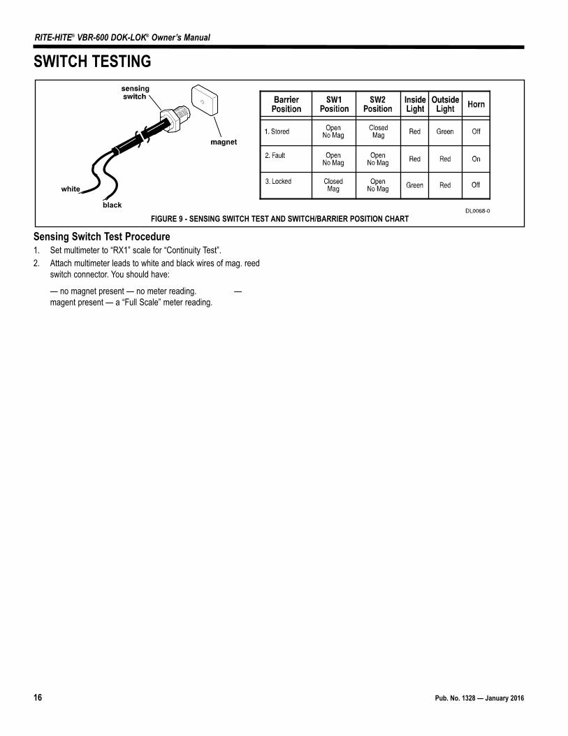
Sensing Switch Test Procedure1. Set multimeter to “RX1” scale for “Continuity Test”.2. Attach multimeter leads to white and black wires of mag. reed
switch connector. You should have:
— no magnet present — no meter reading. —magent present — a “Full Scale” meter reading.
white
black
FIGURE 9 - SENSING SWITCH TEST AND SWITCH/BARRIER POSITION CHART
SWITCH TESTING
Pub. No. 1328 — January 2016 17
RITE-HITE® VBR-600 DOK-LOK® Owner’s Manual
LED STATUS CHART VB
R-60
0VE
RTIC
AL B
ARRI
ER R
ESTR
AIN
T
DOK-LOK LIMIT SWITCH 1 [SW1]
DOK-LOK LIMIT SWITCH 2 [SW2]
UNLOCK INTERLOCK [UNLK ITL]
LOCK PUSH BUTTON
UNLOCK PUSH BUTTON
HORN SILENCE PUSH BUTTONS (1/2/3)
INSIDE RED LIGHT [ISR]
INSIDE GREEN LIGHT [ISG]
CORNER-VU RED LIGHT [CVU RD]
CORNER-VU GREEN LIGHT [CVU GRN]
LEVELER-VU RED LIGHT [LVU RD]
LEVELER-VU GREEN LIGHT [L-VU GRN]
OUTSIDE RED LIGHT [OSR]
OUTSIDE GREEN LIGHT [OSG]
DOK-LOK HORN [HORN]
LEVELER MOTOR CONTACTOR[COMBINED POWER UNIT ONLY]
RESTRAINT OVERLOAD LED [YELLOW]
K1 - GREEN LIGHT INTERLOCK
K2 - SECURITY SYSTEM INTERFACE[IF EQUIPPED]
K2 - COMBINED POWER UNIT[IF EQUIPPED]
MOTOR OUPTUT #1 [M1/RUN]
SOLENOID #1 (RSOL1 / EXTEND)
SOLENOID #2 (RSOL2 / FLOAT)
SOLENOID #3 (RSOL3 / DIVERT)[COMBINED POWER UNIT ONLY]
12VDC POWER SUPPLY OK
TERM
INAL
BLO
CK N
O.
J13.
1J1
3.2
J14.
2M
EMBR
ANE
J7.1
5J7
.16
J12.
1J1
2.2
J12.
3J1
2.4
J11.
2J1
1.1
J7.1
8J1
5.1
N/A
J9.3
J10.
3J1
0.3
J5.4
J7.3
J7.2
J7.1
J2.1
-6PO
WER
BO
ARD
LEDs
--
--
--
--
--
--
--
--
--
--
LD2
LD10
LD9
LD8
LD7
MIC
RO C
ON
TRO
L BO
ARD
LEDs
LD20
LD23
LD30
LD52
LD17
LD19
LD11
LD13
LD18
LD12
LD49
LD48
LD15
LD42
LD50
LD9
LD10
LD10
LD1
LD8
LD6
LD2
-01
.01.
00LO
CKED
STA
TET
F?
--
-F
PF
PF
PP
FF
FF
TT
FF
FT
FT
01.0
1.01
LOCK
ING
SEQ
UEN
CE E
XTEN
DF
F?
M-
-T
FP
FP
FP
FF
TF
FT
TT
FF
TT
01.0
1.05
LOCK
ING
SEQ
UEN
CE R
AISE
FF
?-
--
TF
PF
PF
PF
FT
FF
TT
TF
TT
T01
.01.
06LO
CKIN
G SE
QU
ENCE
RET
RACT
FF
?-
--
TF
PF
PF
PF
FF
FF
TF
FF
TT
T01
.02.
00U
NLO
CKED
STA
TEF
T?
--
-P
FP
FP
FF
PF
FF
FT
FF
FF
FT
01.0
2.01
UN
LOCK
ING
SEQ
UEN
CE E
XTEN
DT
FIT
L-
M-
TF
PF
PF
PF
FT
FF
TT
TF
FT
T01
.02.
06U
NLO
CKIN
G SE
QU
ENCE
LO
WER
FF
ITL
--
-T
FP
FP
FP
FF
TF
FT
TT
TF
TT
01.0
2.07
UN
LOCK
ING
SEQ
UEN
CE R
ETRA
CTF
FIT
L-
--
TF
PF
PF
PF
FF
FF
TF
FF
FF
T01
.04.
00FA
ULT
STA
TE?
??
--
-P
FP
FP
FP
FP
FF
FF
FF
FF
FT
01.0
4.01
FAU
LT S
ILEN
CED
STAT
EF
FT
TF
FF
FP
M-
-?
??
FF
FT
01.1
1.00
OVE
RLO
AD F
AULT
STA
TE?
??
--
-P
FP
FP
FP
FK
FT
FF
FF
FF
FT
NO
.ST
ATE
/ SE
QU
ENCE
NO
.
KEY
? - V
ARYS
DEP
ENDI
NG
ON
OPE
RATI
ON
K - C
ON
TIN
UO
US
CHIR
PDESSERP
NOTT
UB NEH
W STHGIL - M
GNITA
NRETLA - ASEHCTI
WS PID GNIS
U YDAETS OT TES[ G
NIHSALF / GNISL
UP - PFF
O - F]
NO YDAETS - T
NO T
UPNI KC
OLRETNI - LTI
MO
TOR
OVE
RLO
AD R
ESET
PRO
CEDU
REIf
Yello
w L
ED L
D50
is ill
umin
ated
and
the
Dok-
Lok
Horn
is C
hirp
ing,
syst
em is
in a
n O
verlo
ad F
ault
Stat
e.To
rese
t the
mot
or o
verlo
ad:
1) P
ress
and
Hor
n Si
lenc
e #2
Bu�
on u
n�l H
orn
Chirp
s (Ap
prox
imat
ely
5 Se
cond
s).
OR
2) P
ress
and
Rel
ease
Res
trai
nt O
/L B
u�on
on
Mic
ro C
ontr
olle
r Boa
rd.
Whe
n th
e m
otor
ove
rload
has
bee
n re
set,
the
Yello
w L
D50
LED
will
turn
off
and
norm
al o
pera
�on
resu
mes
.If
Dok-
Lok
mot
or s�
ll do
es n
ot ru
n a�
er re
se�
�ng
the
over
load
, che
ck M
otor
Fus
e 10
FU1.
AA
A
POW
ER B
OAR
DO
UTP
UTS
115/
230V
ACIN
PUTS
FIEL
DPU
SH B
UTT
ON
S
MIC
RO C
ON
TRO
L BO
ARD
RELA
Y12
VDC
OU
TPU
TS
18 Pub. No. 1328 — January 2016
RITE-HITE® VBR-600 DOK-LOK® Owner’s Manual
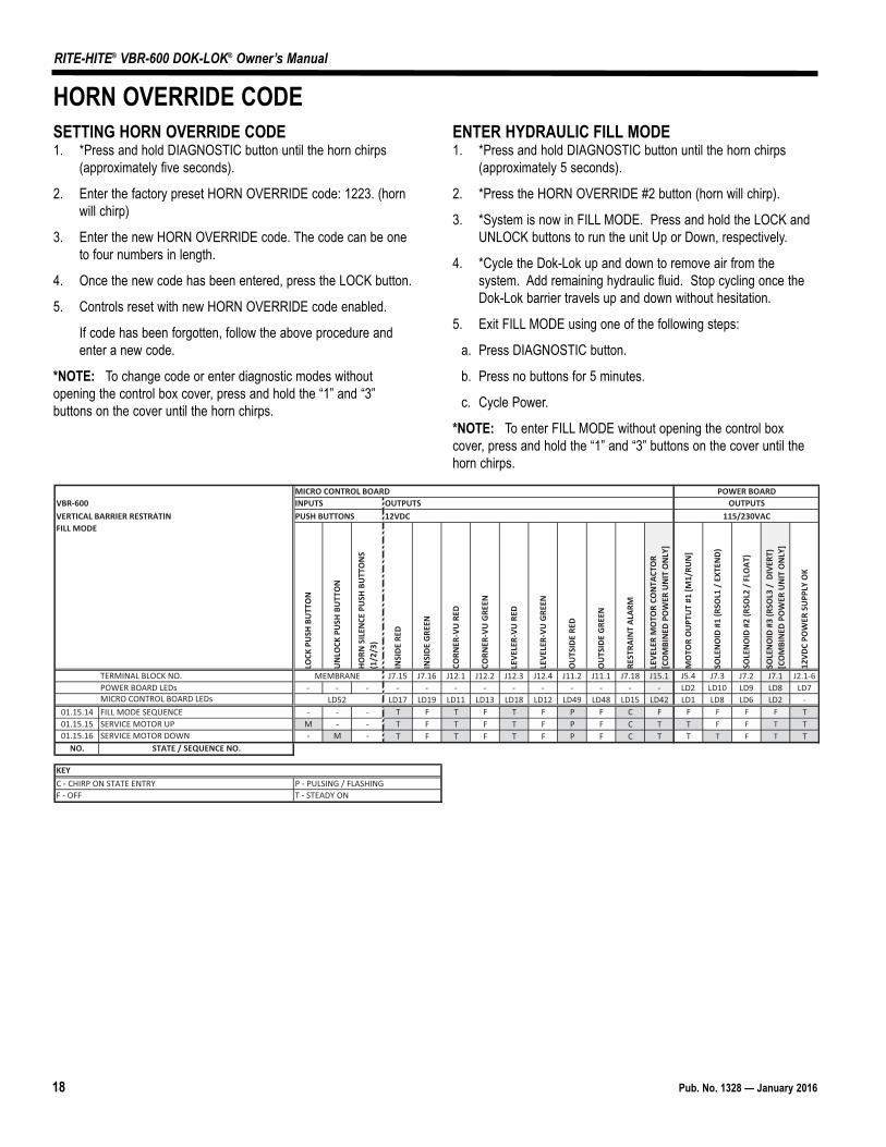
SETTING HORN OVERRIDE CODE1. *Press and hold DIAGNOSTIC button until the horn chirps
(approximately five seconds).
2. Enter the factory preset HORN OVERRIDE code: 1223. (hornwill chirp)
3. Enter the new HORN OVERRIDE code. The code can be oneto four numbers in length.
4. Once the new code has been entered, press the LOCK button.
5. Controls reset with new HORN OVERRIDE code enabled.
If code has been forgotten, follow the above procedure andenter a new code.
*NOTE: To change code or enter diagnostic modes withoutopening the control box cover, press and hold the “1” and “3”buttons on the cover until the horn chirps.
ENTER HYDRAULIC FILL MODE1. *Press and hold DIAGNOSTIC button until the horn chirps
(approximately 5 seconds).
2. *Press the HORN OVERRIDE #2 button (horn will chirp).
3. *System is now in FILL MODE. Press and hold the LOCK andUNLOCK buttons to run the unit Up or Down, respectively.
4. *Cycle the Dok-Lok up and down to remove air from thesystem. Add remaining hydraulic fluid. Stop cycling once theDok-Lok barrier travels up and down without hesitation.
5. Exit FILL MODE using one of the following steps:
a. Press DIAGNOSTIC button.
b. Press no buttons for 5 minutes.
c. Cycle Power.
*NOTE: To enter FILL MODE without opening the control boxcover, press and hold the “1” and “3” buttons on the cover until thehorn chirps.
HORN OVERRIDE CODE
MICRO CONTROL BOARDSTUPTUOSTUPNI006-RBV
CDV21SNOTTUB HSUPNITARTSER REIRRAB LACITREVFILL MODE
LOCK
PU
SH B
UTT
ON
UN
LOCK
PU
SH B
UTT
ON
HORN
SIL
ENCE
PU
SH B
UTT
ON
S (1
/2/3
)
INSI
DE R
ED
INSI
DE G
REEN
CORN
ER-V
U R
ED
CORN
ER-V
U G
REEN
LEVE
LER-
VU R
ED
LEVE
LER-
VU G
REEN
OU
TSID
E RE
D
OU
TSID
E G
REEN
REST
RAIN
T AL
ARM
LEVE
LER
MO
TOR
CON
TACT
OR
[CO
MBI
NED
PO
WER
UN
IT O
NLY
]
MO
TOR
OU
PTU
T #1
[M1/
RUN
]
SOLE
NO
ID #
1 (R
SOL1
/ E
XTEN
D)
SOLE
NO
ID #
2 (R
SOL2
/ F
LOAT
)
SOLE
NO
ID #
3 (R
SOL3
/ D
IVER
T)[C
OM
BIN
ED P
OW
ER U
NIT
ON
LY]
12VD
C PO
WER
SU
PPLY
OK
TERMINAL BLOCK NO. MEMBRANE J7.15 J7.16 J12.1 J12.2 J12.3 J12.4 J11.2 J11.1 J7.18 J15.1 J5.4 J7.3 J7.2 J7.1 J2.1-6POWER BOARD LEDs - - - - - - - - - - - - - LD2 LD10 LD9 LD8 LD7MICRO CONTROL BOARD LEDs LD52 LD17 LD19 LD11 LD13 LD18 LD12 LD49 LD48 LD15 LD42 LD1 LD8 LD6 LD2 -
---ECNEUQES EDOM LLIF41.51.10 T F T F T F P F C F F F F F T--MPU ROTOM ECIVRES51.51.10 T F T F T F P F C T T F F T T-M-NWOD ROTOM ECIVRES61.51.10 T F T F T F P F C T T T F T T
NO. STATE / SEQUENCE NO.
KEYGNIHSALF / GNISLUP - PYRTNE ETATS NO PRIHC - C
NO YDAETS - TFFO - F
115/230VAC
POWER BOARDOUTPUTS
Pub. No. 1328 — January 2016 19
RITE-HITE® VBR-600 DOK-LOK® Owner’s Manual
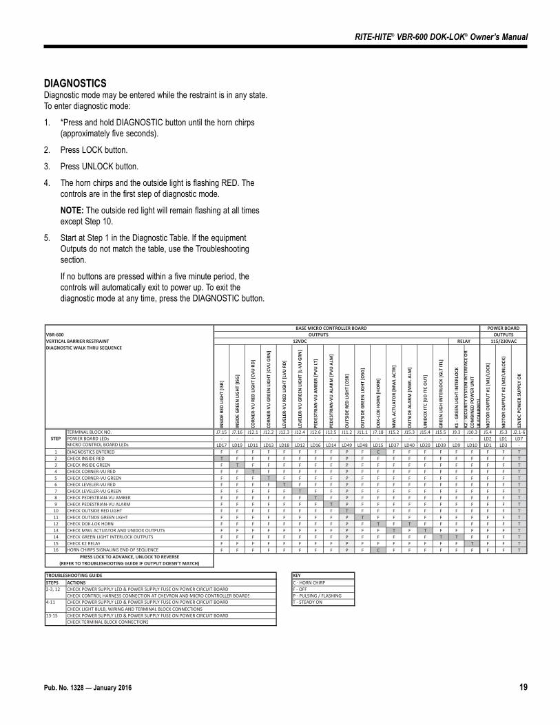
DIAGNOSTICSDiagnostic mode may be entered while the restraint is in any state.To enter diagnostic mode:
1. *Press and hold DIAGNOSTIC button until the horn chirps(approximately five seconds).
2. Press LOCK button.
3. Press UNLOCK button.
4. The horn chirps and the outside light is flashing RED. Thecontrols are in the first step of diagnostic mode.
NOTE: The outside red light will remain flashing at all timesexcept Step 10.
5. Start at Step 1 in the Diagnostic Table. If the equipmentOutputs do not match the table, use the Troubleshootingsection.
If no buttons are pressed within a five minute period, thecontrols will automatically exit to power up. To exit thediagnostic mode at any time, press the DIAGNOSTIC button.
DRAOB REWOPDRAOB RELLORTNOC ORCIM ESABVBR-600 OUTPUTS OUTPUTSVERTICAL BARRIER RESTRAINT ALER CDV21 Y 115/230VACDIAGNOSTIC WALK THRU SEQUENCE
INSI
DE
RED
LIG
HT
[ISR]
INSI
DE
GRE
EN L
IGH
T [IS
G]
CORN
ER-V
U R
ED L
IGH
T [C
VU R
D]
CORN
ER-V
U G
REEN
LIG
HT
[CVU
GRN
]
LEVE
LER-
VU R
ED L
IGH
T [L
VU R
D]
LEVE
LER-
VU G
REEN
LIG
HT
[L-V
U G
RN]
PED
ESTR
IAN
-VU
AM
BER
[PVU
LT]
PED
ESTR
IAN
-VU
ALA
RM [P
VU A
LM]
OU
TSID
E RE
D L
IGH
T [O
SR]
OU
TSID
E G
REEN
LIG
HT
[OSG
]
DO
K-LO
K H
ORN
[HO
RN]
MW
L AC
TUAT
OR
[MW
L AC
TR]
OU
TSID
E AL
ARM
[MW
L AL
M]
UN
IDO
X IT
C [U
D IT
C O
UT]
GRE
EN L
IGH
INTE
RLO
CK [G
LT IT
L]
K1 -
GRE
EN L
IGH
T IN
TERL
OCK
K2 -
SECU
RITY
SYS
TEM
INTE
RFAC
E O
RCO
MBI
NED
PO
WER
UN
IT[IF
EQU
IPPE
D]
MO
TOR
OU
PTU
T #1
[M1/
LOCK
]
MO
TOR
OU
PTU
T #2
(M2/
UN
LOCK
)
12VD
C PO
WER
SU
PPLY
OK
TERMINAL BLOCK NO. J7.15 J7.16 J12.1 J12.2 J12.3 J12.4 J12.6 J12.5 J11.2 J11.1 J7.18 J15.2 J15.3 J15.4 J15.5 J9.3 J10.3 J5.4 J5.3 J2.1-6STEP POWER BOARD LEDs - - - - - - - - - - - - - - - - - LD2 LD1 LD7
MICRO CONTROL BOARD LEDs LD17 LD19 LD11 LD13 LD18 LD12 LD16 LD14 LD49 LD48 LD15 LD37 LD40 LD20 LD39 LD9 LD10 LD1 LD3 -1 DIAGNOSTICS ENTERED F F F F F F F F P F C F F F F F F F F T2 CHECK INSIDE RED T F F F F F F F P F F F F F F F F F F T3 CHECK INSIDE GREEN F T F F F F F F P F F F F F F F F F F T4 CHECK CORNER-VU RED F F T F F F F F P F F F F F F F F F F T5 CHECK CORNER-VU GREEN F F F T F F F F P F F F F F F F F F F T6 CHECK LEVELER-VU RED F F F F T F F F P F F F F F F F F F F T7 CHECK LEVELER-VU GREEN F F F F F T F F P F F F F F F F F F F T8 CHECK PEDESTRIAN-VU AMBER F F F F F F T F P F F F F F F F F F F T9 CHECK PEDESTRIAN-VU ALARM F F F F F F F T P F F F F F F F F F F T
10 CHECK OUTSIDE RED LIGHT F F F F F F F F T F F F F F F F F F F T11 CHECK OUTSIDE GREEN LIGHT F F F F F F F F P T F F F F F F F F F T12 CHECK DOK-LOK HORN F F F F F F F F P F T F T F F F F F F T13 CHECK MWL ACTUATOR AND UNIDOX OUTPUTS F F F F F F F F P F F T F T F F F F F T14 CHECK GREEN LIGHT INTERLOCK OUTPUTS F F F F F F F F P F F F F F T T F F F T15 CHECK K2 RELAY F F F F F F F F P F F F F F F F T F F T16 HORN CHIRPS SIGNALING END OF SEQUENCE F F F F F F F F P F C F F F F F F F F T
TROUBLESHOOTING GUIDE KEYSTEPS ACTIONS C - HORN CHIRP2-3, 12 CHECK POWER SUPPLY LED & POWER SUPPLY FUSE ON POWER CIRC FFO - FDRAOB TIU
CHECK CONTROL HARNESS CONNECTION AT CHEVRON AND MICRO CONTROLLER BOARDS P - PULSING / FLASHING4-11 CHECK POWER SUPPLY LED & POWER SUPPLY FUSE ON POWER CIRCUIT NO YDAETS - TDRAOB
CHECK LIGHT BULB, WIRING AND TERMINAL BLOCK CONNECTIONS13-15 CHECK POWER SUPPLY LED & POWER SUPPLY FUSE ON POWER CIRCUIT BOARD
CHECK TERMINAL BLOCK CONNECTIONS
PRESS LOCK TO ADVANCE, UNLOCK TO REVERSE(REFER TO TROUBLESHOOTING GUIDE IF OUTPUT DOESN’T MATCH)
20 Pub. No. 1328 — January 2016
RITE-HITE® VBR-600 DOK-LOK® Owner’s Manual
100
101
102
103
104
105
106
107
108
109
110
111
112
113
114
115
116
117
118
119
120
121
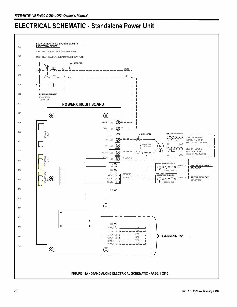
FROM CUSTOMER MAIN POWER & SAFETY PROTECTION DEVICE.
110-120v. 1PH. 60HZ./208-240v. 1PH. 50HZ.
USE 20.0A/10.0A DUAL ELEMENT TIME DELAY FUSE
(1L1)
(N)
(1L1)
(N)DUMMY
L1
SEE NOTE 2
FUSED DISCONNECT(BY OTHERS)
N
G
1FU1 1L1
N
SEE NOTE 7
LD2
LD1
LD9
LD8
LD7
LD10
K3
K2
K1
J3
J5
J7
J2
J11M2
RSOL1
RSOL2
RSOL3
M1
+12VDC
POWER CIRCUIT BOARD
SEE DETAIL - "A"
10FU1
MO
TOR
12FU1
SOLEN
OID
11FU1
PWR SU
PPLY
J212V
(12V)
(12V)
(12V)
(12V)
(12V)
X1/L1
X2/N
M1
M2
MCOM
SCOM
12VDC12VDC12VDC12VDC12VDC12VDC
RSOL1RSOL2RSOL3
J7-3J7-2J7-1
J2-6J2-5J2-4J2-3J2-2J2-1
J3-2
J3-1
J5-4
J5-3
J5-2
J5-1
G120VAC, 0.3 AMPS
(BK) (WH)
POSN CYL "EXTEND" (SOLENOID 1)
RESTRAINT EXTEND SOLENOID
(RSOL1/J73)
(SCOM/J51)
(SCOM/J151)
G
M
(M1/J54)
(MCOM/J52)
THERMAL SWITCH(IN MOTOR)
SEE NOTE 2
G120VAC, 0.3 AMPS
(BK) (WH)
POSN CYL "FLOAT" (SOLENOID 2)
(RSOL2/J72) (SCOM/J151) RESTRAINT FLOAT SOLENOID
115V, 1PH, 50/60HZ14.0/12.4 FLA, 1.0 HP;(OVLD SET AT 12.4 AMPS)
1 3 2 J 4
M1 MCOM
1 2 3 J 4
M1 MCOM
RESTRAINT MOTOR
230V, 1PH, 50/60HZ7.0/6.2 FLA, 1.0 HP;(OVLD SET AT 6.2 AMPS)
ELECTRICAL SCHEMATIC - Standalone Power Unit
FIGURE 11A - STAND ALONE ELECTRICAL SCHEMATIC - PAGE 1 OF 3
Pub. No. 1328 — January 2016 21
RITE-HITE® VBR-600 DOK-LOK® Owner’s Manual
200
201
202
203
204
205
206
207
208
209
210
211
212
213
214
215
216
217
218
219
220
221
LD10
SCTY INTFC
CR2
TO SECURITY SYSTEM INTFC(IF EQUIPPED)
(UNLK ITL/J43)
LEVELER STORED
UNLOCK INTERLOCK CIRCUIT
(COM)
(AUTO ITC/J166)
OVERHEAD DOORCLOSED
(HORN OVRD/J164)
(CTRL PWR/J163)
(OSLT ITC/J162)
(ISLT ITC/J161)
(COM)
(COM)
(COM)
(COM)
(COM)INSIDELIGHT ITC
OUTSIDELIGHT ITC
CONTROLPOWER ENABLE
HORN OVERRIDEENABLE
AUTO ITC
(COM)
(COM)
MECH/FA ITC PHOTOEYE ITC
OUTSIDE LT ITC
INSIDE LT ITC
J2
J7
U1
VR1
J16
J17 J3J4
TERM1
J1
J12
J15
J11
J5JP2
UN-LK PBLK PB
PB1 PB2 PB3 E-STOPLOWER PBLIP-OUT PB
ISR ISG
RAISE PB
CR1
LK
SOL2SPARE
UNLK
PB PRESS
OVLD LOKINSLT ITC
OSLT ITC
CTRL PWR
KYD HRN OVRD
UD ITC IN
AUTO ITC
OSR
OSG
PED-VU AMB
PED-VU ALRM
LVLR-VU GRN
LVLR-VU RD
CRNR-VU GRN
CRNR-VU RED
GLT ITL
MWL ALARM
MWL ACTR
LVLR CONTR
SOL3
UNIDOX ITC
HORN
JP1 JP3
TERM 2
J8
OUTSIDE LIGHTS
12VDC
R (RD)135mA
(WH)
G (RD)135mA
(WH)
LD7
J2
+12VDC
DETAIL - "A"
(42/12V)
COM
COM
RESTRAINT POWER CKT BD(LOWER RIGHT CORNER )
N.C.
N.O.
COM
N.C.
N.O.
COM
CR2
H
INSIDE HORN
12V, 0.03A
1 2 3 4 5 6 7
12VDC12VDC12VDC12VDC12VDC12VDC
SEE DETAIL - "C"
(40/OSR)
(41/OSG)
(42/12V)
K1/K2 SPECS:250V AC/30VDC RES. LOAD, 1A MAX
LD24
LD26
LD28
LD27
LD25
LD31
LD33
LD34
LD17
LD19
LD9
LD1
LD2
LD6
LD4
LD3
LD50
LD52
LD36
LD15
LD16
LD14
LD12
LD18
LD13
LD11
LD39
LD20
LD40
LD37
LD42
LD48
LD10
LD49
LD46
LD44
LD43
LD41
LD38
OSGOSR
LVLR CNTR
MWL ACTRMWL ALM
UD ITC OUTGLT ITLCVU RDCVU GNLVU RDLVU GN
PVU ALMPVU LT
AUTO ITC
UD ITC IN
KYD HORN OVRD
CTRL PWROSLT ITC
ISLT ITC
LD35
μSD
MICRO CONTROL CIRCUIT BOARD
HORN+ (WH/RD)
HORN- (WH/BK)
HORN- (WH/BK)
OUTSIDE LTCIRCUITLED LIGHTS ONLY
K1
K2
12V(BL)J155(BL)
12V(BL)
12V(BL)
SSR1
(A2) (A1)12VDC, 0.1W
TO LED BOARD(SEE DETAIL - "B")
J13
J14
SW1
SW2
PED-VU EN
PED-VU DET
OHD ITL
UNLK ITL
ARTD
SOL1SPARE
LD23
LD21
LD22
LD30
LD29
LD32
LD20
LD7 LD8
COMARTDUNLK ITLOHD ITLCOMCOMCOMPVU DETPVU ENSW2SW1
DIAG
SW2
SW6
RES O/L
RESET
J16-1J16-2J16-3J16-4J16-5J16-6
J17-1
J17-2
J12-6J12-5J12-4J12-3J12-2J12-1J15-5J15-4J15-3J15-2J15-1
ACB
ACB
J11-2J11-1
J2-6J2-5J2-4J2-3J2-2J2-1
J13-1J13-2J13-3J13-4J13-5J13-6J14-1J14-2J14-3J14-4J14-5 8
GLT ITL
GREEN LIGHT INTERLOCK(IF EQUIPPED(SEE DETAIL D)
GLT ITLGLT ITLGLT ITL
PB
HYD. ITC
SS
HORN OVERRIDE
SS
CONTROL POWER
DOK-GUARDIAN ENG
(OPTIONAL EQUIPMENT - REMOVE FACTORY JUMPER WHEN INSTALLING)
OPTIONAL EQUIPMENT:COMPETITIVE LEVELER INTERLOCK
(OPT
ION
AL
EQU
IPM
ENT)
FACTORY JUMPER:(18GA WH/BL)
"STORED" SENSOR (SW2)
N.O.H.C.
(WH) (BK)
"RIG" SENSOR (SW1)
N.O.
(WH) (BK)
(6/COM) (7/SW2)
LOCKCIRCUIT
(6/COM)
UNLOCKCIRCUIT
(6/COM) (5/SW1)
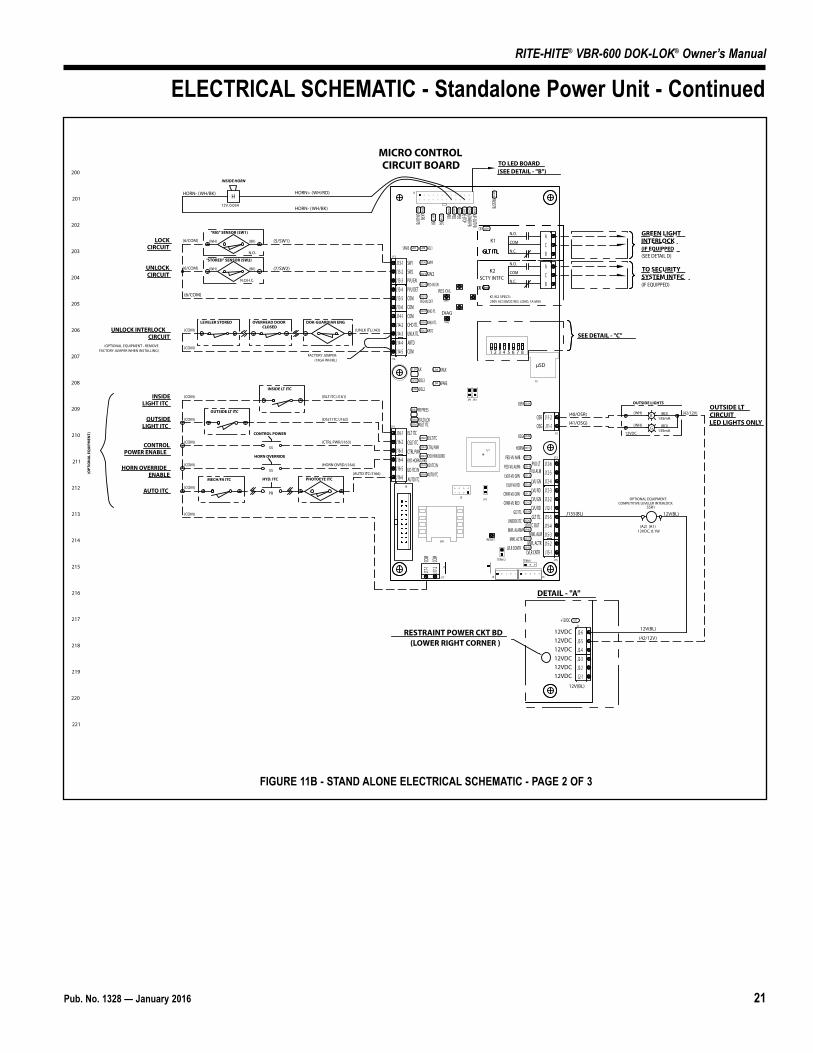
ELECTRICAL SCHEMATIC - Standalone Power Unit - Continued
FIGURE 11B - STAND ALONE ELECTRICAL SCHEMATIC - PAGE 2 OF 3
22 Pub. No. 1328 — January 2016
RITE-HITE® VBR-600 DOK-LOK® Owner’s Manual
DETAIL - "C" RESTRAINT MICRO CB DIP SWITCH SETTINGS
FLASH
UP:
SW3
LIGHTSDOWN:
STEADY
1 2 3 4 5 6 7 8
300
301
302
303
304
305
306
307
308
309
310
311
312
313
314
315
316
317
318
319
320
321
1
U4
J1
OSLT RED
OSLT
D64
D63
5
1
INSD
10
6
SYSTEM CONTROL HARNESS
(FROM MICRO PCB)
RIBBON CABLES(FROM MEMBRANE LABEL)
11J4J3
RESE
T
DETAIL B - BACK OF COVER
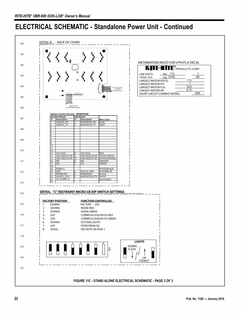
FACTORY POSITION FUNCTION CONTROLLED1 (DOWN) FACTORY USE2 (DOWN) INSIDE RED3 (DOWN) INSIDE GREEN4 (UP) CORNER & LEVELER-VU RED5 (UP) CORNER & LEVELER-VU GREEN6 (DOWN) OUTSIDE LIGHTS7 (UP) PEDESTRIAN-VU8 (XXXX) SEE NOTE ON PAGE 1
INFORMATION REQ'D FOR V/PH/FLA DECAL
PRODUCTS CORPR
LINE VOLTS: PH: TOTAL FLA: HZ: LARGEST MOTOR VOLTS: LARGEST MOTOR PH:LARGEST MOTOR FLA:LARGEST MOTOR HP:SHORT CIRCUIT CURRENT RATING:
11510.95 60
1
5KA
115
10.00.75
1
GREEN
GREEN
J7 Description J1 Description1 USART2_RX 1 MICROPCB_RX BLUE
2 USART2_TX 2 MICROPCB_TX GRAY
3
4
5
6
7
8
9
10
11
12
13 12V [Vext] 5 12V [Vext] RED
14 OSG INDICATOR 9 OSG INDICATOR WHITE/GREEN
15 OSR INDICATOR 10 OSR INDICATOR WHITE/ORANGE
16 ISR 8 ISR ORANGE
17 ISG 7 ISG GREEN
18
19 HORN [-] WHITE/BLACK
20 GND 4 DIGITAL GND WHITE/BLUE
21 RESERVED 6 RESERVED BLACK
22 USART2_RTS 3 MICROPCB_RTS WHITE
23 12V [HORN +]
24
System Control Harness - MEMBRANEuControl Board LED Board
Wire Color
WHITE/RED
ELECTRICAL SCHEMATIC - Standalone Power Unit - Continued
FIGURE 11C - STAND ALONE ELECTRICAL SCHEMATIC - PAGE 3 OF 3

Pub. No. 1328 — January 2016 23
RITE-HITE® VBR-600 DOK-LOK® Owner’s Manual
J7
VR1
J13
LVU RD
LVU GRN
CVU GN
CVU RD
(J124/LVGN)
(J123/LVRD)
(J122/CVGN)
(J121/CVRD)
(12V)
(12V)
(12V)
(12V)
J13-1
J13-2
J13-3
J13-4
J13-5
J13-6
J14-1
J14-2
J14-3
14-4
14-5
J16-1
J16-2
J16-3
J16-4
J16-5
J16-6
J17-1
J17-2
J12-6
J12-5
J12-4
J12-3
J12-2
J12-1
J15-5
J15-4
J15-3
J15-2
J15-1
J11-2
J11-1
N.O.
CR1
N.C.
N.O.
CR2
N.C.
J2-6
J2-5
J2-4
J2-3
J2-2
J2-1
LEVELER-VU LIGHT PAIR
GR
12VDC, 110mA
(BLU)
(BRN)
(BLK)
CORNER-VU LIGHT PAIR
GR
12VDC, 110mA
(BLU)
(BRN)
(BLK)
J2
12VDC
12VDC
12VDC
12VDC
12VDC
12VDC
MICRO CONTROL CIRCUIT BOARD
RESTRAINT POWER CB
CORNER/LEVELER-VU WIRING
RITE-VU WIRE LABELS
ORIGINAL RELEASE PLUG & PLAY VERSION
12V 12V
IN3 PVDT
OUT0 CVRD
OUT1 CVGN
OUT2 PVLT
OUT3 LVRD
OUT4 LVGN
OUT5 PVAL
GND COM
ELECTRICAL SCHEMATIC - Corner/Leveler-Vu Wiring
FIGURE 12 - CORNER/LEVELER-VU ELECTRICAL SCHEMATIC
24 Pub. No. 1328 — January 2016
RITE-HITE® VBR-600 DOK-LOK® Owner’s Manual
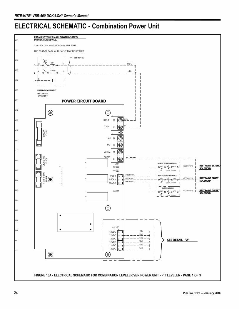
100
101
102
103
104
105
106
107
108
109
110
111
112
113
114
115
116
117
118
119
120
121
FROM CUSTOMER MAIN POWER & SAFETY PROTECTION DEVICE.
110-120v. 1PH. 60HZ./208-240v. 1PH. 50HZ.
USE 20.0A/10.0A DUAL ELEMENT TIME DELAY FUSE
(1L1)
(N)
(1L1)
(N)DUMMY
L1
SEE NOTE 2
FUSED DISCONNECT(BY OTHERS)
N
G
1FU1 1L1
N
SEE NOTE 7
LD2
LD1
LD9
LD8
LD7
LD10
K3
K2
K1
J3
J5
J7
J2
J11M2
RSOL1
RSOL2
RSOL3
M1
+12VDC
POWER CIRCUIT BOARD
SEE DETAIL - "A"
10FU1
MO
TOR
12FU1
SOLEN
OID
11FU1
PWR SU
PPLY
J212V
(12V)
(12V)
(12V)
(12V)
(12V)
X1/L1
X2/N
M1
M2
MCOM
SCOM
12VDC12VDC12VDC12VDC12VDC12VDC
RSOL1RSOL2RSOL3
J7-3J7-2J7-1
J2-6J2-5J2-4J2-3J2-2J2-1
J3-2
J3-1
J5-4
J5-3
J5-2
J5-1
G120VAC, 0.3 AMPS
(BK) (WH)
POSN CYL "EXTEND" (SOLENOID 1)
RESTRAINT EXTEND SOLENOID
(RSOL1/J73)
(SCOM/J51)
G120VAC, 0.3 AMPS
(BK) (WH)
POSN CYL "FLOAT" (SOLENOID 2)
(RSOL2/J72) RESTRAINT FLOAT SOLENOID
G120VAC, 0.3 AMPS
(BK) (WH)
DIVERT (SOLENOID 3)
RESTRAINT DIVERT SOLENOID
(RSOL3/J71)
RESTRAINT EXTEND SOLENOID
(SCOM/J51)
RESTRAINT FLOAT SOLENOID
RESTRAINT DIVERT SOLENOID
(SCOM/J151)
(SCOM/J151)
(SCOM/J151)
ELECTRICAL SCHEMATIC - Combination Power Unit
FIGURE 13A - ELECTRICAL SCHEMATIC FOR COMBINATION LEVELER/VBR POWER UNIT - PIT LEVELER - PAGE 1 OF 3
Pub. No. 1328 — January 2016 25
RITE-HITE® VBR-600 DOK-LOK® Owner’s Manual
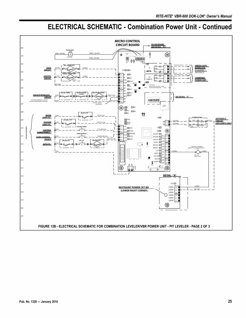
200
201
202
203
204
205
206
207
208
209
210
211
212
213
214
215
216
217
218
219
220
221
LD10
CMBD PU
CR2
COMBINEDPOWER UNIT
(UNLK ITL/J43)
LEVELER STORED
UNLOCK INTERLOCK CIRCUIT
(COM)
(AUTO ITC/J166)
OVERHEAD DOORCLOSED
(HORN OVRD/J164)
(CTRL PWR/J163)
(OSLT ITC/J162)
(ISLT ITC/J161)
(COM)
(COM)
(COM)
(COM)
(COM)INSIDELIGHT ITC
OUTSIDELIGHT ITC
CONTROLPOWER ENABLE
HORN OVERRIDEENABLE
AUTO ITC
(COM)
(COM)
MECH/FA ITC PHOTOEYE ITC
OUTSIDE LT ITC
INSIDE LT ITC
J2
J7
U1
VR1
J16
J17 J3J4
TERM1
J1
J12
J15
J11
J5JP2
UN-LK PBLK PB
PB1 PB2 PB3 E-STOPLOWER PBLIP-OUT PB
ISR ISG
RAISE PB
CR1
LK
SOL2SPARE
UNLK
PB PRESS
OVLD LOKINSLT ITC
OSLT ITC
CTRL PWR
KYD HRN OVRD
UD ITC IN
AUTO ITC
OSR
OSG
PED-VU AMB
PED-VU ALRM
LVLR-VU GRN
LVLR-VU RD
CRNR-VU GRN
CRNR-VU RED
GLT ITL
MWL ALARM
MWL ACTR
LVLR CONTR
SOL3
UNIDOX ITC
HORN
JP1 JP3
TERM 2
J8
OUTSIDE LIGHTS
12VDC
R (RD)135mA
(WH)
G (RD)135mA
(WH)
LD7
J2
+12VDC
DETAIL - "A"
(42/12V)
COM
COM
RESTRAINT POWER CKT BD(LOWER RIGHT CORNER )
N.C.
N.O.
COM
N.C.
N.O.
COM
CR2
H
INSIDE HORN
12V, 0.03A
1 2 3 4 5 6 7
12VDC12VDC12VDC12VDC12VDC12VDC
SEE DETAIL - "C"
(40/OSR)
(41/OSG)
(42/12V)
K1/K2 SPECS:250V AC/30VDC RES. LOAD, 1A MAX
LD24
LD26
LD28
LD27
LD25
LD31
LD33
LD34
LD17
LD19
LD9
LD1
LD2
LD6
LD4
LD3
LD50
LD52
LD36
LD15
LD16
LD14
LD12
LD18
LD13
LD11
LD39
LD20
LD40
LD37
LD42
LD48
LD10
LD49
LD46
LD44
LD43
LD41
LD38
OSGOSR
LVLR CNTR
MWL ACTRMWL ALM
UD ITC OUTGLT ITLCVU RDCVU GNLVU RDLVU GN
PVU ALMPVU LT
AUTO ITC
UD ITC IN
KYD HORN OVRD
CTRL PWROSLT ITC
ISLT ITC
LD35
μSD
MICRO CONTROL CIRCUIT BOARD
HORN+ (WH/RD)
HORN- (WH/BK)
HORN- (WH/BK)
OUTSIDE LTCIRCUITLED LIGHTS ONLY
K1
K2
12V(BL)J155(BL)
12V(BL)
SSR1
(A2) (A1)12VDC, 0.1W
TO LED BOARD(SEE DETAIL - "B")
J13
J14
SW1
SW2
PED-VU EN
PED-VU DET
OHD ITL
UNLK ITL
ARTD
SOL1SPARE
LD23
LD21
LD22
LD30
LD29
LD32
LD20
LD7 LD8
COMARTDUNLK ITLOHD ITLCOMCOMCOMPVU DETPVU ENSW2SW1
DIAG
SW2
SW6
RES O/L
RESET
J16-1J16-2J16-3J16-4J16-5J16-6
J17-1
J17-2
J12-6J12-5J12-4J12-3J12-2J12-1J15-5J15-4J15-3J15-2J15-1
ACB
ACB
J11-2J11-1
J2-6J2-5J2-4J2-3J2-2J2-1
J13-1J13-2J13-3J13-4J13-5J13-6J14-1J14-2J14-3J14-4J14-5 8
GLT ITL
GREEN LIGHT INTERLOCK(IF EQUIPPED(SEE DETAIL D)
GLT ITLGLT ITLGLT ITL
PB
HYD. ITC
SS
HORN OVERRIDE
SS
CONTROL POWER
DOK-GUARDIAN ENG
(OPTIONAL EQUIPMENT - REMOVE FACTORY JUMPER WHEN INSTALLING)
OPTIONAL EQUIPMENT:COMPETITIVE LEVELER INTERLOCK
(OPT
ION
AL
EQU
IPM
ENT)
FACTORY JUMPER:(18GA WH/BL)
"STORED" SENSOR (SW2)
N.O.H.C.
(WH) (BK)
"RIG" SENSOR (SW1)
N.O.
(WH) (BK)
(6/COM) (7/SW2)
LOCKCIRCUIT
(6/COM)
UNLOCKCIRCUIT
(6/COM) (5/SW1)
ELECTRICAL SCHEMATIC - Combination Power Unit - Continued
FIGURE 13B - ELECTRICAL SCHEMATIC FOR COMBINATION LEVELER/VBR POWER UNIT - PIT LEVELER - PAGE 2 OF 3
26 Pub. No. 1328 — January 2016
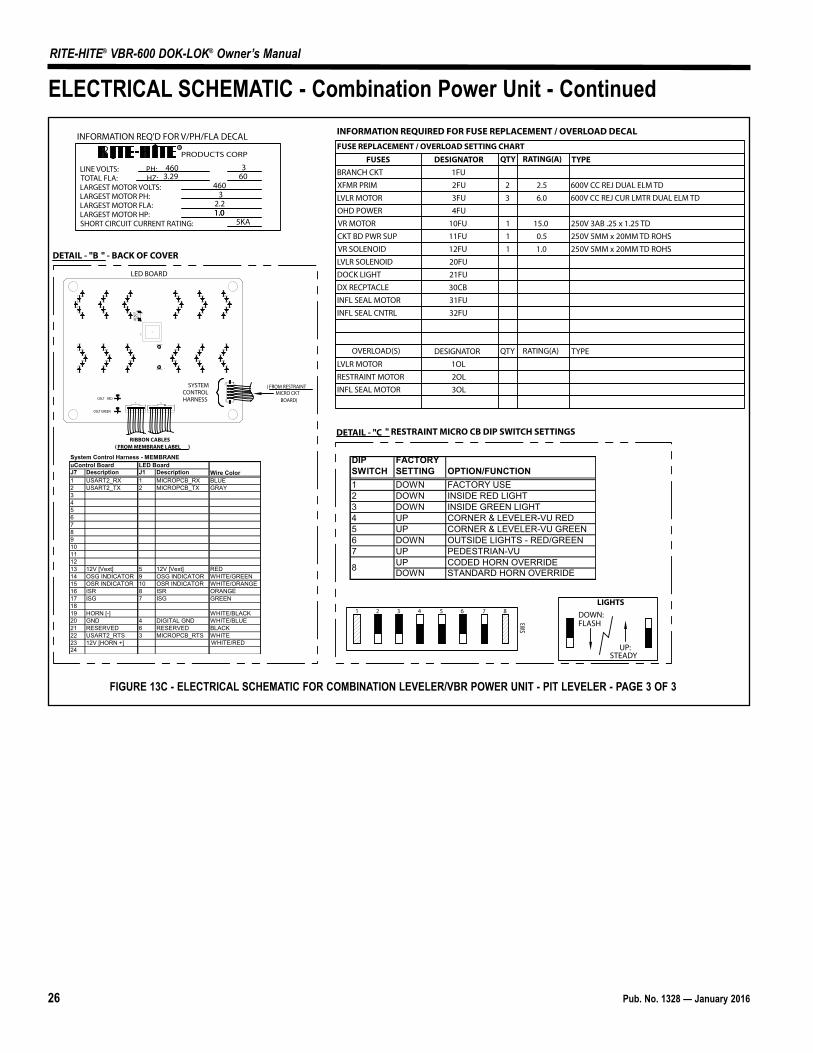
RITE-HITE® VBR-600 DOK-LOK® Owner’s Manual
INFORMATION REQUIRED FOR FUSE REPLACEMENT / OVERLOAD DECALFUSE REPLACEMENT / OVERLOAD SETTING CHART
FUSES DESIGNATOR QTY RATING(A) TYPEBRANCH CKT
XFMR PRIM
LVLR MOTOR
OHD POWER
VR MOTOR
VR SOLENOID
CKT BD PWR SUP
DOCK LIGHT
DX RECPTACLE
INFL SEAL MOTOR
LVLR MOTOR
RESTRAINT MOTOR
OVERLOAD(S) DESIGNATOR QTY RATING(A) TYPE
1FU
2FU
3FU
10FU
12FU
21FU
20FU
30CB
31FU
1OL
2OL
600V CC REJ DUAL ELM TD2.5
6.03 600V CC REJ CUR LMTR DUAL ELM TD
460 360
1.0
3.292
LVLR SOLENOID
INFL SEAL CNTRL 32FU
4FU
11FU
INFL SEAL MOTOR 3OL
1
U4
J1
OSLT REDD64D64
D63D63
5
1
10
6
( FROM RESTRAINT MICRO CKT
BOARD)
RIBBON CABLES( FROM MEMBRANE LABEL )
11J3
RESE
T
DETAIL - "B " - BACK OF COVER
INFORMATION REQ'D FOR V/PH/FLA DECAL
PRODUCTS CORPR
2.21.0
OSLT GREEN
5KA
LINE VOLTS: PH: TOTAL FLA: HZ: LARGEST MOTOR VOLTS: LARGEST MOTOR PH:LARGEST MOTOR FLA:LARGEST MOTOR HP:SHORT CIRCUIT CURRENT RATING: 1
1
1
0.5
15.0 250V 3AB .25 x 1.25 TD
250V 5MM x 20MM TD ROHS
1.0 250V 5MM x 20MM TD ROHS
4603
DETAIL - "C " RESTRAINT MICRO CB DIP SWITCH SETTINGS
FLASH
UP:
SW3
LIGHTSDOWN:
STEADY
1 2 3 4 5 6 7 8
J4
LED BOARD
SYSTEM CONTROL HARNESS
J7 Description J1 Description1 USART2_RX 1 MICROPCB_RX BLUE
2 USART2_TX 2 MICROPCB_TX GRAY
3
4
5
6
7
8
9
10
11
12
13 12V [Vext] 5 12V [Vext] RED
14 OSG INDICATOR 9 OSG INDICATOR WHITE/GREEN
15 OSR INDICATOR 10 OSR INDICATOR WHITE/ORANGE
16 ISR 8 ISR ORANGE
17 ISG 7 ISG GREEN
18
19 HORN [-] WHITE/BLACK
20 GND 4 DIGITAL GND WHITE/BLUE
21 RESERVED 6 RESERVED BLACK
22 USART2_RTS 3 MICROPCB_RTS WHITE
23 12V [HORN +]
24
System Control Harness - MEMBRANEuControl Board LED Board
Wire Color
WHITE/RED
DIP SWITCH
FACTORY SETTING OPTION/FUNCTION
1 DOWN FACTORY USE
2 DOWN INSIDE RED LIGHT
3 DOWN INSIDE GREEN LIGHT
4 UP CORNER & LEVELER-VU RED
5 UP CORNER & LEVELER-VU GREEN
6 DOWN OUTSIDE LIGHTS - RED/GREEN
7 UP PEDESTRIAN-VU
UP CODED HORN OVERRIDE
DOWN STANDARD HORN OVERRIDE8
ELECTRICAL SCHEMATIC - Combination Power Unit - Continued
FIGURE 13C - ELECTRICAL SCHEMATIC FOR COMBINATION LEVELER/VBR POWER UNIT - PIT LEVELER - PAGE 3 OF 3

Pub. No. 1328 — January 2016 27
RITE-HITE® VBR-600 DOK-LOK® Owner’s Manual
NOTES
28 Pub. No. 1328 — January 2016
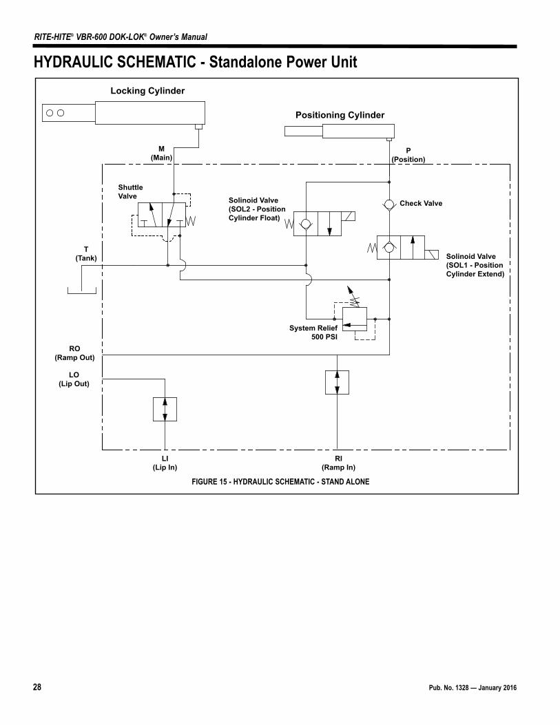
RITE-HITE® VBR-600 DOK-LOK® Owner’s Manual
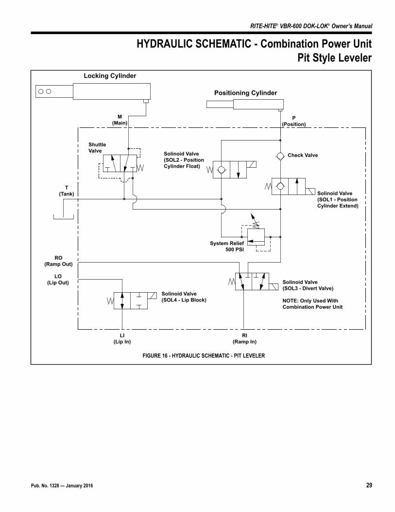
LO(Lip Out)
T(Tank)
RO(Ramp Out)
LI(Lip In)
M(Main)
RI(Ramp In)
P(Position)
Locking Cylinder
Positioning Cylinder
Solinoid Valve (SOL1 - Position Cylinder Extend)
Check Valve
System Relief500 PSI
ShuttleValve Solinoid Valve
(SOL2 - PositionCylinder Float)
HYDRAULIC SCHEMATIC - Standalone Power Unit
FIGURE 15 - HYDRAULIC SCHEMATIC - STAND ALONE
Pub. No. 1328 — January 2016 29
RITE-HITE® VBR-600 DOK-LOK® Owner’s Manual
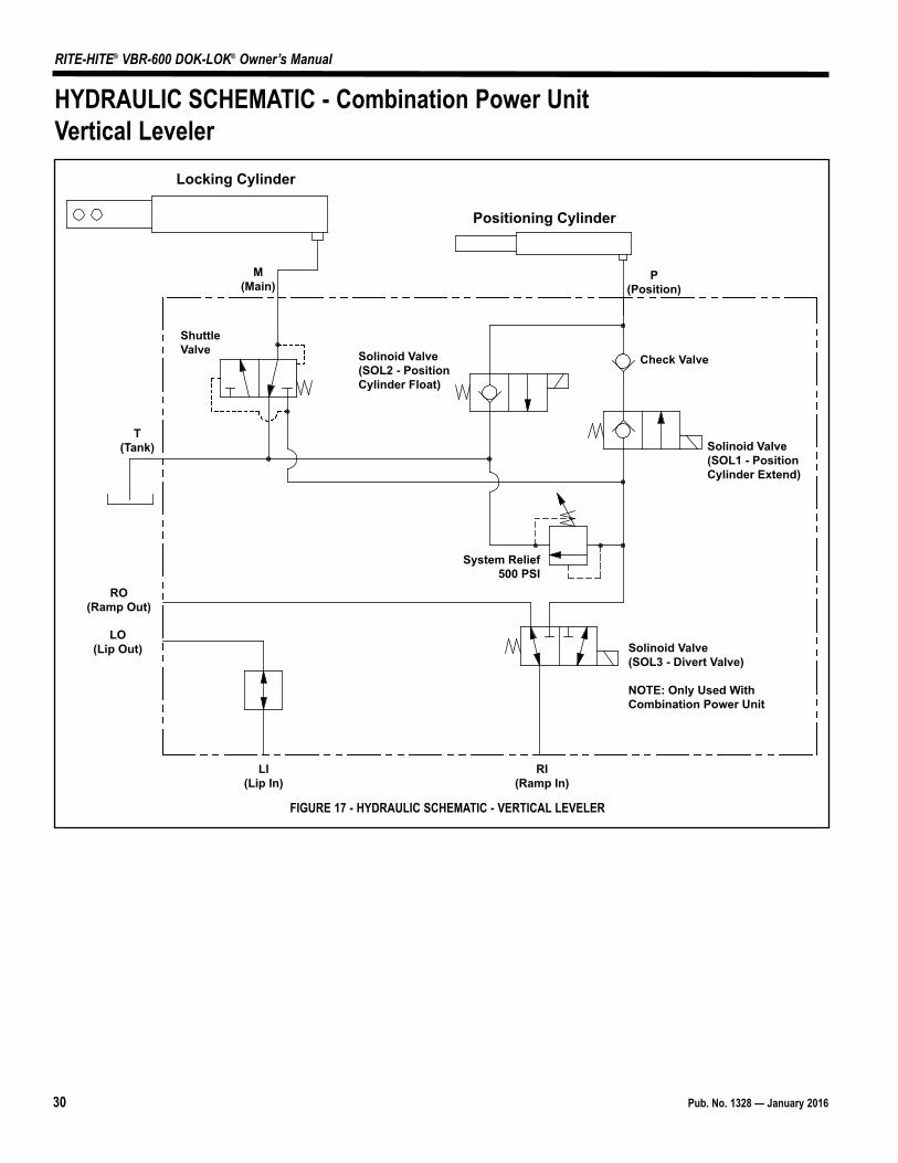
LO(Lip Out)
T(Tank)
RO(Ramp Out)
LI(Lip In)
M(Main)
RI(Ramp In)
P(Position)
Locking Cylinder
Positioning Cylinder
Solinoid Valve (SOL4 - Lip Block)
Solinoid Valve (SOL3 - Divert Valve)
NOTE: Only Used WithCombination Power Unit
Check Valve
System Relief500 PSI
Solinoid Valve (SOL1 - Position Cylinder Extend)
ShuttleValve Solinoid Valve
(SOL2 - PositionCylinder Float)
HYDRAULIC SCHEMATIC - Combination Power UnitPit Style Leveler
FIGURE 16 - HYDRAULIC SCHEMATIC - PIT LEVELER
30 Pub. No. 1328 — January 2016
RITE-HITE® VBR-600 DOK-LOK® Owner’s Manual
LO(Lip Out)
T(Tank)
RO(Ramp Out)
LI(Lip In)
M(Main)
RI(Ramp In)
P(Position)
Locking Cylinder
Positioning Cylinder
Solinoid Valve (SOL3 - Divert Valve)
NOTE: Only Used WithCombination Power Unit
Check Valve
System Relief500 PSI
Solinoid Valve (SOL1 - Position Cylinder Extend)
ShuttleValve Solinoid Valve
(SOL2 - PositionCylinder Float)
HYDRAULIC SCHEMATIC - Combination Power UnitVertical Leveler
FIGURE 17 - HYDRAULIC SCHEMATIC - VERTICAL LEVELER
Pub. No. 1328 — January 2016 31
RITE-HITE® VBR-600 DOK-LOK® Owner’s Manual
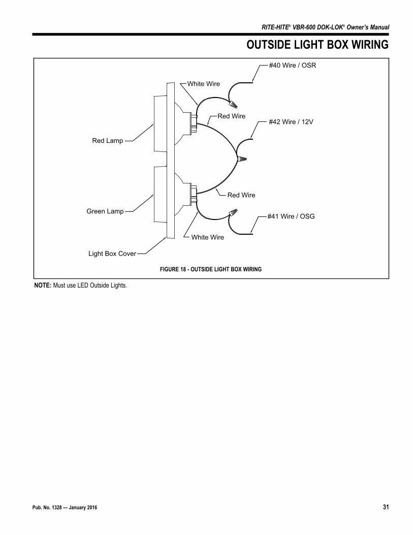
NOTE: Must use LED Outside Lights.
OUTSIDE LIGHT BOX WIRING #40 Wire / OSR
White Wire
Red Wire#42 Wire / 12V
White Wire
Red Wire
#41 Wire / OSG
Red Lamp
Green Lamp
Light Box Cover
FIGURE 18 - OUTSIDE LIGHT BOX WIRING
32 Pub. No. 1328 — January 2016
RITE-HITE® VBR-600 DOK-LOK® Owner’s Manual
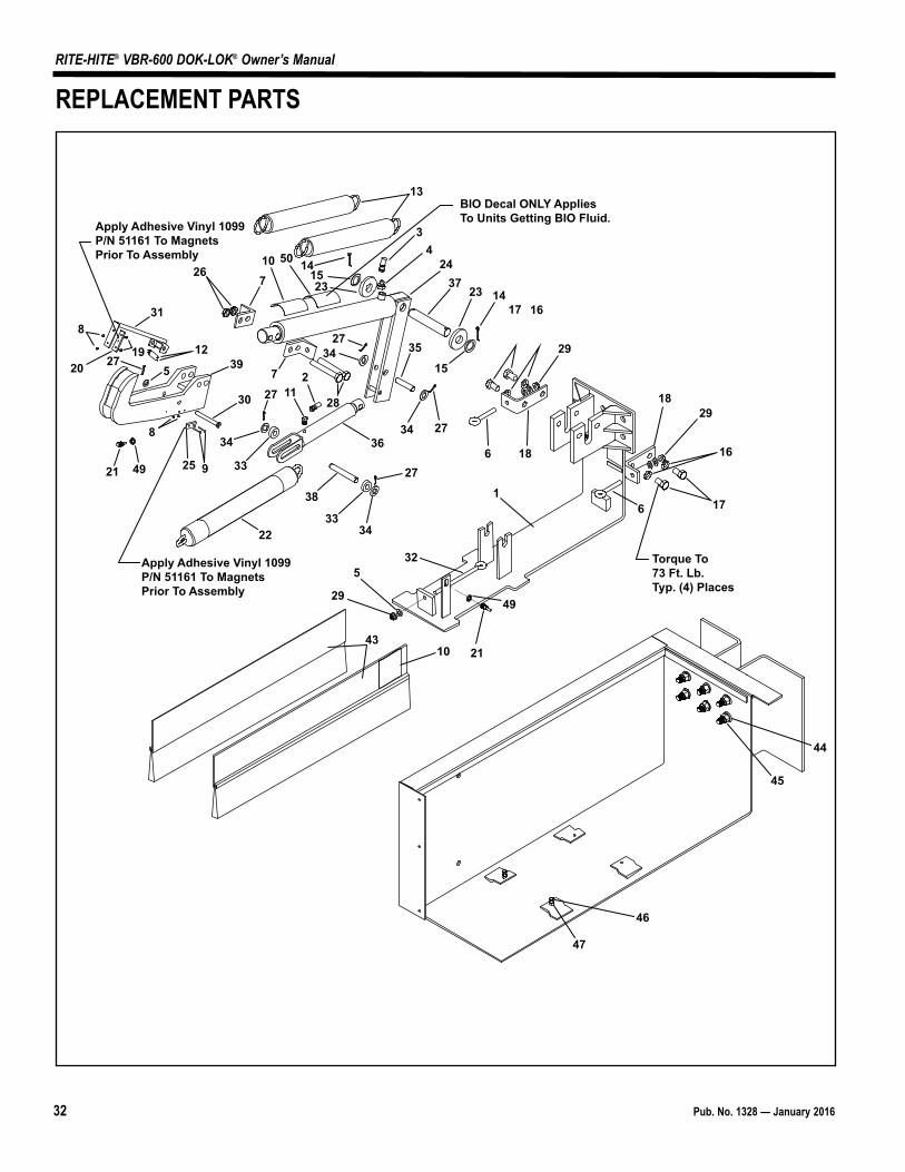
127
38
3334
32
29
5
211043
22
33
34
925
30
21
8
Apply Adhesive Vinyl 1099P/N 51161 To MagnetsPrior To Assembly
8
20 275
19 1239
31
26710 14
1523
727
211
2734
28
36
13
34
2437
23
35
34 27
15
1417 16
29
186
Torque To73 Ft. Lb.Typ. (4) Places
Apply Adhesive Vinyl 1099P/N 51161 To MagnetsPrior To Assembly
1829
16
176
44
45
46
47
50
49
49
BIO Decal ONLY Applies To Units Getting BIO Fluid.
REPLACEMENT PARTS
Pub. No. 1328 — January 2016 33
RITE-HITE® VBR-600 DOK-LOK® Owner’s Manual
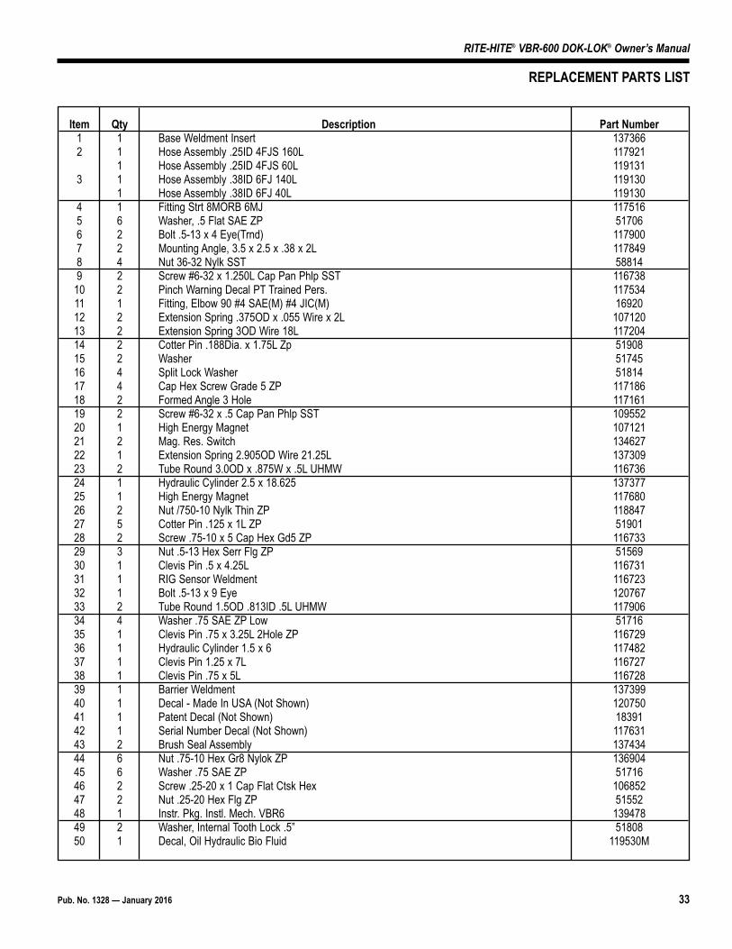
Item Qty Description Part Number1 1 Base Weldment Insert 1373662 1 Hose Assembly .25ID 4FJS 160L 117921
1 Hose Assembly .25ID 4FJS 60L 1191313 1 Hose Assembly .38ID 6FJ 140L 119130
1 Hose Assembly .38ID 6FJ 40L 1191304 1 Fitting Strt 8MORB 6MJ 1175165 6 Washer, .5 Flat SAE ZP 517066 2 Bolt .5-13 x 4 Eye(Trnd) 1179007 2 Mounting Angle, 3.5 x 2.5 x .38 x 2L 1178498 4 Nut 36-32 Nylk SST 588149 2 Screw #6-32 x 1.250L Cap Pan Phlp SST 116738
10 2 Pinch Warning Decal PT Trained Pers. 11753411 1 Fitting, Elbow 90 #4 SAE(M) #4 JIC(M) 1692012 2 Extension Spring .375OD x .055 Wire x 2L 10712013 2 Extension Spring 3OD Wire 18L 11720414 2 Cotter Pin .188Dia. x 1.75L Zp 5190815 2 Washer 5174516 4 Split Lock Washer 5181417 4 Cap Hex Screw Grade 5 ZP 11718618 2 Formed Angle 3 Hole 11716119 2 Screw #6-32 x .5 Cap Pan Phlp SST 10955220 1 High Energy Magnet 10712121 2 Mag. Res. Switch 13462722 1 Extension Spring 2.905OD Wire 21.25L 13730923 2 Tube Round 3.0OD x .875W x .5L UHMW 11673624 1 Hydraulic Cylinder 2.5 x 18.625 13737725 1 High Energy Magnet 11768026 2 Nut /750-10 Nylk Thin ZP 11884727 5 Cotter Pin .125 x 1L ZP 5190128 2 Screw .75-10 x 5 Cap Hex Gd5 ZP 11673329 3 Nut .5-13 Hex Serr Flg ZP 5156930 1 Clevis Pin .5 x 4.25L 11673131 1 RIG Sensor Weldment 11672332 1 Bolt .5-13 x 9 Eye 12076733 2 Tube Round 1.5OD .813ID .5L UHMW 11790634 4 Washer .75 SAE ZP Low 5171635 1 Clevis Pin .75 x 3.25L 2Hole ZP 11672936 1 Hydraulic Cylinder 1.5 x 6 11748237 1 Clevis Pin 1.25 x 7L 11672738 1 Clevis Pin .75 x 5L 11672839 1 Barrier Weldment 13739940 1 Decal - Made In USA (Not Shown) 12075041 1 Patent Decal (Not Shown) 1839142 1 Serial Number Decal (Not Shown) 11763143 2 Brush Seal Assembly 13743444 6 Nut .75-10 Hex Gr8 Nylok ZP 13690445 6 Washer .75 SAE ZP 5171646 2 Screw .25-20 x 1 Cap Flat Ctsk Hex 10685247 2 Nut .25-20 Hex Flg ZP 5155248 1 Instr. Pkg. Instl. Mech. VBR6 13947849 2 Washer, Internal Tooth Lock .5” 5180850 1 Decal, Oil Hydraulic Bio Fluid 119530M
REPLACEMENT PARTS LIST
34 Pub. No. 1328 — January 2016
RITE-HITE® VBR-600 DOK-LOK® Owner’s Manual
1
2
34
56
7
8
9
10 11
1213
14
15
16
1718
16
19
20
16
16
1718
2
3
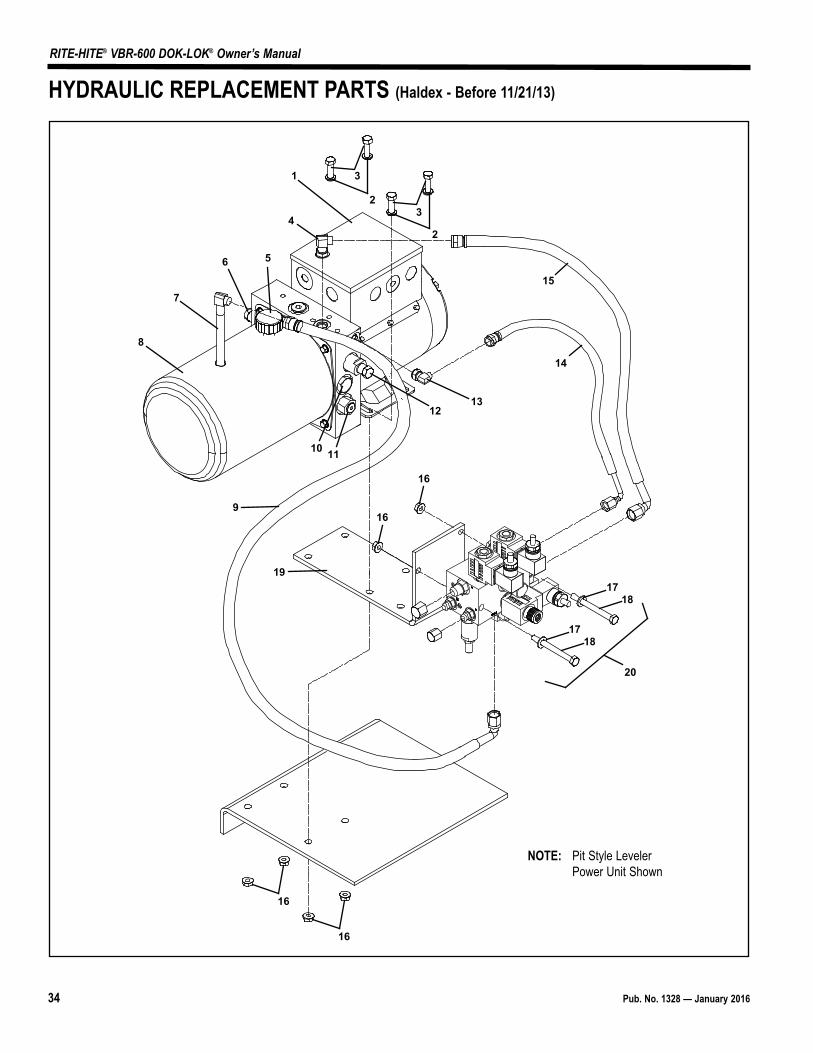
HYDRAULIC REPLACEMENT PARTS (Haldex - Before 11/21/13)
NOTE: Pit Style LevelerPower Unit Shown

Pub. No. 1328 — January 2016 35
RITE-HITE® VBR-600 DOK-LOK® Owner’s Manual
Item Qty Description Part Number1 1 Power Unit - Standalone Dok-Lok, 120V 1PH 116679
(Ref. To Leveler Parts Manual For Combo Dock Leveler/Dok-Lok Power Unit)2 4 Split Lock Washer, .31 517693 4 Hex Head Bolt, .313-18 x 1, GR5 516274 2 90Deg. Hydraulic Fitting, #4 SAE(M) #6 JIC(M) 552675 1 Hydraulic Tank Cap *6 1 Shuttle Valve *7 1 90Deg. Hydraulic Fitting W/Internal Nyl. Tube 1175178 1 Hydraulic Tank *9 1 Hose Assembly, .38ID 18L 117527
10 1 Check Valve *11 1 System Relief Valve *12 1 Sequence Valve *13 1 90Deg. Hydraulic Fitting, #4 SAE(M) #4 JIC(M) 1692014 1 Hose Assembly, .25ID 10L 11752315 1 Hose Assembly, .38ID 14L 11752416 6 Nut, .313-18 5153517 2 Flat Washer, .312 5172818 2 Hex Head Bolt, .313-18 x 3.25L 11751819 1 Mounting Angle, 10 x 5.38 x .25 11749320 1 Dok-Lok Manifold Complete, Standalone Unit (Incl. valves & solenoids) 139659
1 Dok-Lok Manifold Complete, Combo Unit - Pit Leveler (Incl. valves & sol.) 1393951 Dok-Lok Manifold Complete, Combo Unit - Vert. Leveler (Incl. valves & sol.) 139656
HYDRAULIC REPLACEMENT PARTS LIST(Haldex - Before 11/21/13)
36 Pub. No. 1328 — January 2016
RITE-HITE® VBR-600 DOK-LOK® Owner’s Manual
1
5
2
4
87
13 (T)
2 (RO)14 (P) VBR6
15 (LO) VBR6
11
13 (M)
19
13 (RI)15 (LI)
11
16
3
9
12
6
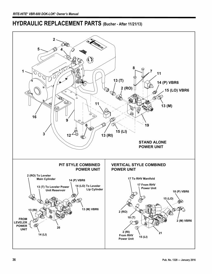
STAND ALONEPOWER UNIT
PIT STYLE COMBINEDPOWER UNIT
VERTICAL STYLE COMBINEDPOWER UNIT
2 (RO) To Leveler Main Cylinder
13 (T) To Leveler Power Unit Reservoir
14 (P) VBR6
14 (LO) To Leveler Lip Cylinder
13 (M) VBR6
20
14 (LI)
13 (RI)
FROMLEVELER
POWERUNIT
17 To RHV Manifold
17 From RHV Power Unit
18 (P) VBR6
15 (LO)
2 (M) VBR6
2115 (LI)
2 (RO)
2 (RI)From RHVPower Unit
10 (T)
HYDRAULIC REPLACEMENT PARTS (Bucher - After 11/21/13)
Pub. No. 1328 — January 2016 37
RITE-HITE® VBR-600 DOK-LOK® Owner’s Manual
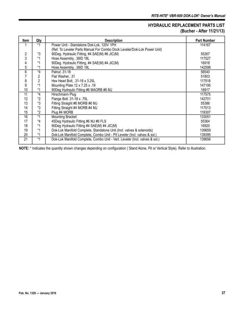
Item Qty Description Part Number1 *1 Power Unit - Standalone Dok-Lok, 120V 1PH 114167
(Ref. To Leveler Parts Manual For Combo Dock Leveler/Dok-Lok Power Unit)2 *3 90Deg. Hydraulic Fitting, #4 SAE(M) #6 JIC(M) 552673 *1 Hose Assembly, .38ID 18L 1175274 *1 90Deg. Hydraulic Fitting, #4 SAE(M) #4 JIC(M) 169185 *1 Hose Assembly, .38ID 18L 1425986 *4 Palnut .31-18 565407 2 Flat Washer, .31 518038 2 Hex Head Bolt, .31-18 x 3.25L 1175189 *1 Mounting Plate 12 x 7.25 x .19 147195
10 *1 90Deg Hydraulic Fitting #6 MAORB #6 MJ 1691711 *4 Hirschmann Plug 11757512 *2 Flange Bolt .31-18 x .75L 14270113 *3 Fitting Straight #6 MORB #6 MJ 5538614 *3 Fitting Straight #4 MORB #4 MJ 11751315 *2 Plug #4 MORB 11830716 *1 Mounting Bracket 13305117 *4 45Deg Hydraulic Fitting #6 MJ #6 FLS 5536418 *1 90Deg Hydraulic Fitting #4 SAE(M) #4 JIC(M) 1692019 *1 Dok-Lok Manifold Complete, Standalone Unit (Incl. valves & solenoids) 13965920 *1 Dok-Lok Manifold Complete, Combo Unit - Pit Leveler (Incl. valves & sol.) 13939521 *1 Dok-Lok Manifold Complete, Combo Unit - Vert. Leveler (Incl. valves & sol.) 139656
HYDRAULIC REPLACEMENT PARTS LIST(Bucher - After 11/21/13)
NOTE: * Indicates the quantity shown changes depending on configuration ( Stand Alone, Pit or Vertical Style). Refer to illustration.
38 Pub. No. 1328 — January 2016
RITE-HITE® VBR-600 DOK-LOK® Owner’s Manual
1
24
5
56
1
9
4
4
3
8
9
12
4
7
7
10
11
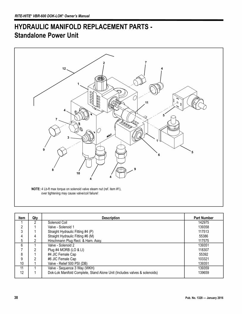
Item Qty Description Part Number1 2 Solenoid Coil 1429752 1 Valve - Solenoid 1 1393583 1 Straight Hydraulic Fitting #4 (P) 1175134 4 Straight Hydraulic Fitting #6 (M) 553865 2 Hirschmann Plug Rect. & Harn. Assy. 1175756 1 Valve - Solenoid 2 1393517 2 Plug #4 MORB (LO & LI) 1183078 1 #4 JIC Female Cap 553929 2 #6 JIC Female Cap 103321
10 1 Valve - Relief 500 PSI (DB) 13935111 1 Valve - Sequence 3 Way (WKH) 13935912 1 Dok-Lok Manifold Complete, Stand Alone Unit (Includes valves & solenoids) 139659
HYDRAULIC MANIFOLD REPLACEMENT PARTS -Standalone Power Unit
NOTE: 4 Lb-ft max torque on solenoid valve steam nut (ref. item #1),over tightening may cause valve/coil failure!
Pub. No. 1328 — January 2016 39
RITE-HITE® VBR-600 DOK-LOK® Owner’s Manual
1
2
3
1
4
5
6
67
8
1
1
95
5
4
10
11
14
12
13
Item Qty Description Part Number1 4 Solenoid Coil 1429752 1 Valve - Solenoid 1 1393583 1 Valve - Solenoid 3 1393554 3 Straight Hydraulic Fitting #4 (LO, LI, & P) 1175135 3 Straight Hydraulic Fitting #6 (M, RI, & T) 553866 4 Hirschmann Plug Rect. & Harn. Assy. 1175757 1 Valve - Solenoid 2 1393518 1 Valve - Solenoid 4 1393569 2 90Deg. Hydraulic Fitting, #4 SAE(M) #6 JIC(M) (RO) 55267
10 1 #4 JIC Female Cap 5539211 1 #6 JIC Female Cap 10332112 1 Valve - Relief 500 PSI (DB) 13935713 1 Valve - Sequence 3 Way (WKH) 13935914 1 Dok-Lok Manifold Complete, Combo Unit - Pit Leveler (Incl. valves & sol.) 139395
HYDRAULIC MANIFOLD REPLACEMENT PARTS -Pit Style Leveler
NOTE: 4 Lb-ft max torque on solenoid valve steam nut (ref. item #1),over tightening may cause valve/coil failure!

40 Pub. No. 1328 — January 2016
RITE-HITE® VBR-600 DOK-LOK® Owner’s Manual
1
23
14
5
6
67
1
5
9
5
4
1011
13
12
Item Qty Description Part Number1 3 Solenoid Coil 1429752 1 Valve - Solenoid 1 1393583 1 Valve - Solenoid 3 1393554 2 Fitting Plug 4 MORB (LO, LI) 1183075 3 90 Deg. Hydraulic Fitting, #6 SAE(M) #6 JIC(M) (RI) 552676 3 Hirschmann Plug Rect. & Harn. Assy. 117575
7 1Valve - Solenoid 2 1393519 1 Fitting, #6 MORB #6 MJ (T) 55386
10 1 90 Deg. Hydraulic Fitting, #4 SAE(M) #4 JIC(M) (P) 1692011 1 Valve - Relief 500 PSI (D8) 13935712 1 Valve - Sequence 3 way (WKH) 13935913 1 Dok-Lok Manifold Complete, Combo Unit - Vertical Leveler (Incl. valves & sol.) 139656
HYDRAULIC MANIFOLD REPLACEMENT PARTS -Vertical Leveler
NOTE: 4 Lb-ft max torque on solenoid valve steam nut (ref. item #1),over tightening may cause valve/coil failure!
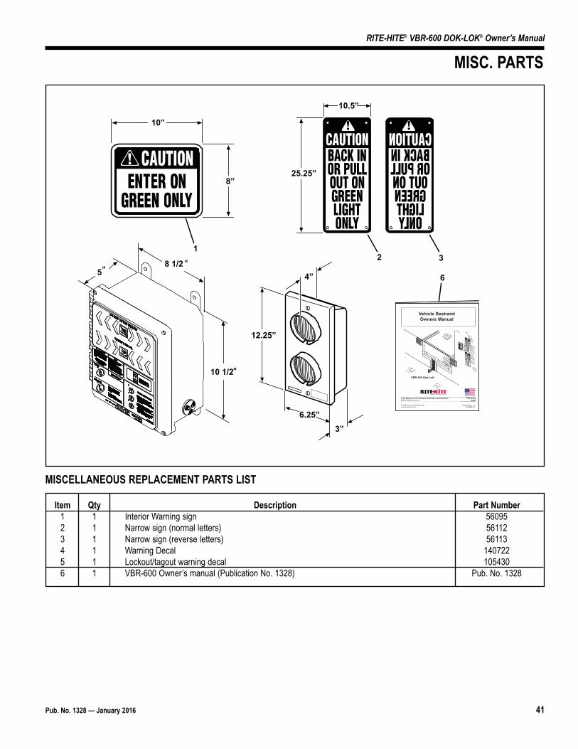
Pub. No. 1328 — January 2016 41
RITE-HITE® VBR-600 DOK-LOK® Owner’s Manual
MISC. PARTS
Item Qty Description Part Number1 1 Interior Warning sign 560952 1 Narrow sign (normal letters) 561123 1 Narrow sign (reverse letters) 561134 1 Warning Decal 1407225 1 Lockout/tagout warning decal 1054306 1 VBR-600 Owner’s manual (Publication No. 1328) Pub. No. 1328
MISCELLANEOUS REPLACEMENT PARTS LIST
10”
8”
1
3”6.25”
12.25”
4”
PRINTED IN U.S.A. RITE-HITE PRINT SHOP PUBLICATION NO. 1191Copyright 2004, 2005, 2006 SEPTEMBER 2006
Effective9/06
Vehicle RestraintOwners Manual
This Manual Covers Restraints Built After Serial Numbers:05GD150001W and up
6
2 3
25.25”
10.5”
VBR-500 Dok-Lok®
MADE IN U.S.A.
10 1/2
58 1/2

42 Pub. No. 1328 — January 2016
RITE-HITE® VBR-600 DOK-LOK® Owner’s Manual
307
301
308
104
102,103,705,706
311
312
209,503
208,502
701, 702, 703, 704, 707
202203,204
205201, 708, 709
210
206
207
206
207
309
601
602
211,501
800
DO NOT ENTER TRAILER
ENTER TRAILER
MIL
WAU
KEE,
WIS
CON
SIN
1-
800-
456-
0600
OUTSIDE LIGHTS
UNLOCK
LOCK DOK-LOK®
1
11
1
3
2
HORN OVERRIDE
KEYED OPTION
T12
L11
(NOTE: ITEMS 302-305, 313 NOT SHOWN.)
L1
X2/N
SOL1SOL2SOL3
LOCK
UNLOCK
12VDC12VDC12VDC12VDC12VDC12VDC
NEUTRAL
NEUTRAL
J13-1J13-2J13-3J13-4J13-5J13-6J14-1J14-2J14-314-414-5
J16-1J16-2J16-3J16-4J16-5J16-6
J17-1
J17-2
J12-6J12-5J12-4J12-3J12-2J12-1J15-5J15-4J15-3J15-2J15-1
ACB
ACB
J11-2J11-1
J1
Y1
U5U4
U3
U2
U1
SW1
R77
R76
R75
R74
R73
R72
R71
R70
R69
R68
R67
R66
R65
R64
R63
R62
R61
R60
R59
R58
R57
R56
R55
R54
R53
R52
R51
R50
R49
R48
R47
R45R44
R43R42R41R40R39R38
R35
R34
R33
R32
R31R30R29R28R27R26
R25
R24
R23
R22R21
R20R19
R18
R17
R16
R15
R14
R13
R12R11
R10R9R8
R7
R6R5
R4R3 R2 R1
L2
J4J3
J2
D77
D76
D75
D74
D73
D72
D71
D70
D69
D68
D67
D66D
65
D62
D61
C29
C28
C27
C26
C25
C24
C23
C22
C21
C20
C19
C18
C17
C16C15C14
C13C12
C11C10
C9 C8
C7
C6 C5
C4
C3
C2C1
D1
D2
D3
D4
D5
D6
D7
D8
D9
D10
D11
D12
D13
D14
D15
D16
D17
D18
D19
D20
D21
D22
D23
D24
D25
D26
D27
D28
D29
D30
D31
D32
D33
D34
D35
D36
D37
D38
D39
D40
D41
D42
D43
D44
D45
D46
D47
D48
D49
D50
D51
D52
D53
D54
D55
D56
D57
D58
D59
D60
D63
D64
802
803
801
806
805
804
ELECTRICAL REPLACEMENT PARTS
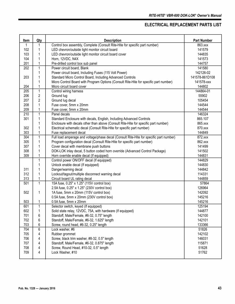
Pub. No. 1328 — January 2016 43
RITE-HITE® VBR-600 DOK-LOK® Owner’s Manual
Item Qty Description Part Number1 1 Control box assembly, Complete (Consult Rite-Hite for specific part number) 863.xxx
102 1 LED chevron/outside light monitor circuit board 141579103 1 LED chevron/outside light monitor circuit board cover 144835104 1 Horn, 12VDC, N4X 141573201 1 Pre-drilled control box sub panel 144757202 1 Power circuit board, Blank 141580
1 Power circuit board, Including Fuses (115 Volt Power) 142126-02203 1 Standard Micro Control Board, Including Advanced Controls 141578-861D108
1 Micro Control Board with Program Options (Consult Rite-Hite for specific part number) 141578-xxx204 1 Micro circuit board cover 144802205 1 Control wiring harness 144864-01206 2 Ground lug 55902207 2 Ground lug decal 105454208 1 Fuse cover, 5mm x 20mm 144544209 1 Fuse cover, 5mm x 20mm 144544210 1 Panel decals 146324301 1 Standard Enclosure with decals, English, Including Advanced Controls 865.107
1 Enclosure with decals other than above (Consult Rite-Hite for specific part number) 865.xxx302 1 Electrical schematic decal (Consult Rite-Hite for specific part number) 870.xxx303 1 Fuse replacement decal 144849304 1 Full load amperage and voltage/phase decal (Consult Rite-Hite for specific part number) 872.xxx305 1 Program configuration decal (Consult Rite-Hite for specific part number) 862.xxx307 1 Cover decal with membrane push buttons 141499308 1 DOK-LOK inlay decal, 5 button coded horn override (Advanced Control Package) 141502309 1 Horn override enable decal (If equipped) 144831
1 Control power ON/OFF decal (If equipped) 1448291 Unlock enable decal (If equipped) 144830
311 1 Danger/warning decal 144842312 1 Lockout/tagout/multiple disconnect warning decal 114331313 1 Circuit board UL rating decal 144859501 1 15A fuse, 0.25" x 1.25" (115V control box) 57864
2.5A fuse, 0.25" x 1.25" (230V control box) 126964502 1 1A fuse, 5mm x 20mm (115V control box) 142092
0.5A fuse, 5mm x 20mm (230V control box) 145216503 1 0.5A fuse, 5mm x 20mm 145216601 1 Selector switch, keyed (If equipped) 125194602 1 Solid state relay, 12VDC, 75A, with hardware (If equipped) 144877701 6 Standoff, Male/Female, #6-32, 0.75" length 142100702 6 Standoff, Male/Female, #6-32, 1.625" length 142101703 6 Screw, round head, #6-32, 0.25" length 133366704 6 Lock washer, #6 51826705 4 Rubber grommet 142102706 4 Screw, black trim washer, #8-32, 0.5" length 146031707 4 Standoff, Male/Female, #6-32, 0.875" length 115871708 4 Screw, Round Head, #10-32, 0.5" length 51628709 4 Lock Washer, #10 51762
ELECTRICAL REPLACEMENT PARTS LIST
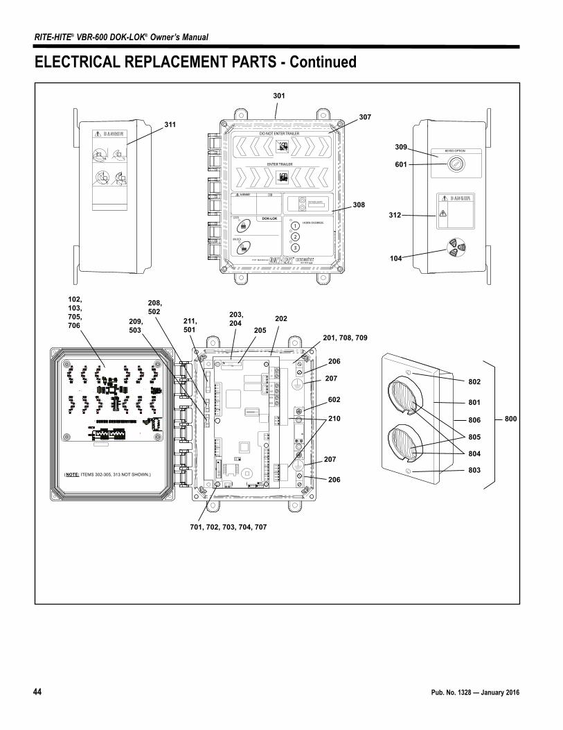
44 Pub. No. 1328 — January 2016
RITE-HITE® VBR-600 DOK-LOK® Owner’s Manual
307
301
308
104
102,103,705,706
311
312
209,503
208,502
701, 702, 703, 704, 707
202203,204
205201, 708, 709
210
206
207
206
207
309
601
602
211,501
800
DO NOT ENTER TRAILER
ENTER TRAILER
MIL
WAU
KEE,
WIS
CON
SIN
1-
800-
456-
0600
OUTSIDE LIGHTS
UNLOCK
LOCK DOK-LOK®
1
11
1
3
2
HORN OVERRIDE
KEYED OPTION
T12
L11
(NOTE: ITEMS 302-305, 313 NOT SHOWN.)
L1
X2/N
SOL1SOL2SOL3
LOCK
UNLOCK
12VDC12VDC12VDC12VDC12VDC12VDC
NEUTRAL
NEUTRAL
J13-1J13-2J13-3J13-4J13-5J13-6J14-1J14-2J14-314-414-5
J16-1J16-2J16-3J16-4J16-5J16-6
J17-1
J17-2
J12-6J12-5J12-4J12-3J12-2J12-1J15-5J15-4J15-3J15-2J15-1
ACB
ACB
J11-2J11-1
J1
Y1
U5U4
U3
U2
U1
SW1
R77
R76
R75
R74
R73
R72
R71
R70
R69
R68
R67
R66
R65
R64
R63
R62
R61
R60
R59
R58
R57
R56
R55
R54
R53
R52
R51
R50
R49
R48
R47
R45R44
R43R42R41R40R39R38
R35
R34
R33
R32
R31R30R29R28R27R26
R25
R24
R23
R22R21
R20R19
R18
R17
R16
R15
R14
R13
R12R11
R10R9R8
R7
R6R5
R4R3 R2 R1
L2
J4J3
J2
D77
D76
D75
D74
D73
D72
D71
D70
D69
D68
D67
D66D
65
D62
D61
C29
C28
C27
C26
C25
C24
C23
C22
C21
C20
C19
C18
C17
C16C15C14
C13C12
C11C10
C9 C8
C7
C6 C5
C4
C3
C2C1
D1
D2
D3
D4
D5
D6
D7
D8
D9
D10
D11
D12
D13
D14
D15
D16
D17
D18
D19
D20
D21
D22
D23
D24
D25
D26
D27
D28
D29
D30
D31
D32
D33
D34
D35
D36
D37
D38
D39
D40
D41
D42
D43
D44
D45
D46
D47
D48
D49
D50
D51
D52
D53
D54
D55
D56
D57
D58
D59
D60
D63
D64
802
803
801
806
805
804
ELECTRICAL REPLACEMENT PARTS - Continued

Pub. No. 1328 — January 2016 45
RITE-HITE® VBR-600 DOK-LOK® Owner’s Manual
Item Qty Description Part Number800 1 LED Outside Light Assembly, Complete 115798801 1 LED Oustide Light Assembly, Doesn't Include Base 128458802 2 Screw, round head #6-32, 0.75" length 18364803 1 LED Outside Light Bulb, Red 128448804 1 LED Outside Light Bulb, Green 128449805 2 LED Light Socket 116894806 1 Outside Light Enclosure Base 18277
ELECTRICAL REPLACEMENT PARTS LIST
46 Pub. No. 1328 — January 2016
RITE-HITE® VBR-600 DOK-LOK® Owner’s Manual
NOTES
Pub. No. 1328 — January 2016 47
RITE-HITE® VBR-600 DOK-LOK® Owner’s Manual
NOTES
Global Sales & Service Office:
RITE-HITE8900 N. Arbon DriveP.O. Box 245020Milwaukee, Wisconsin 53224
Phone: 414-355-26001-800-456-0600www.ritehite.com
Representatives in all Major Cities
RITE-HITE STANDARD WARRANTY
Rite-Hite warrants that its products will be free from defects in design, materials, and workmanship for a period of 365 days from thedate of shipment. All claims for breach of this warranty must be made within 30 days after the defect is or can, with reasonable care, bedetected and in no event no more than 30 days after the warranty has expired. In order to be entitled to the benefits of this warranty, theproducts must have been properly installed, maintained, and operated within their rated capacities and/or specified design parameters,and not otherwise abused. Periodic lubrication and adjustment is the sole responsibility of the owner. This warranty is Rite-Hite’sexclusive warranty. RITE-HITE EXPRESSLY DISCLAIMS ALL IMPLIED WARRANTIES, INCLUDING THE IMPLIED WARRANTIES OFMERCHANTABILITY AND FITNESS. Non-standard warranties, if any, must be specified by Rite-Hite in writing.
In the event of any defects covered by this warranty, Rite-Hite will remedy such defects by repairing or replacing any defective equipmentor parts, bearing all the costs for parts, labor, and transportation. This shall be the exclusive remedy for all claims whether based oncontract, negligence, or strict liability.
LIMITATION OF LIABILITY
RITE-HITE SHALL NOT IN ANY EVENT BE LIABLE FOR ANY LOSS OF USE OF ANY EQUIPMENT OR INCIDENTAL ORCONSEQUENTIAL DAMAGES OF ANY KIND, WHETHER FOR BREACH OF WARRANTY, NEGLIGENCE, OR STRICT LIABILITY.