heat treating data book - seco/warwick group » seco/warwick
TRANSCRIPT

Heat Treating Data Book
Tenth Edition E-Book
Published by SECO/Warwick Corporation
180 Mercer St., PO Box 908, Meadville, PA 16335 USA www.secowarwick.com
SECO/WARWICK Corp. is a member of the SECO/WARWICK Group (SWG) of companies
The SECO/WARWICK Heat Treating Data Book contains information about heat treating metals. This book is not intended as a text, but rather as a collection of frequently used reference data to serve persons interested in heat treating technology.
If it saves you time, we feel it will have accomplished its purpose.
The information herein has been compiled from sources which we believe to be reliable, but we assume no responsibility or liability for its accuracy or for the result of any application made, nor do we assume any liability for infringement of any patent which may result from the application of such information.
2011 SECO/WARWICK All Rights Reserved
1
2
Table of Contents
Chapter 1 – Steel Data 5
A.I.S.I. - S.A.E. STEEL SPECIFICATIONS 5 BASIC NUMBERING SYSTEM FOR SAE STEELS 5 TABLE 1A - CARBON STEEL COMPOSITIONS APPLICABLE TO SEMIFINISHED PRODUCTS FOR FORGING, HOT ROLLED AND COLD FINISHED BARS, WIRE RODS, AND SEAMLESS TUBING 7 TABLE 1B - CARBON STEEL COMPOSITONS APPLICABLE ONLY TO STRUCTURAL SHAPES, PLATES, STRIP, SHEETS AND WELDED TUBING 9 TABLE 2A - FREE CUTTING (RESULFURIZED) CARBON STEEL COMPOSITIONS 11 TABLE 2B - FREE CUTTING (REPHOSPHORIZED AND RESULFURIZED) CARBON STEEL COMPOSITIONS 12 TABLE 3A - HIGH MANGANESE CARBON STEEL COMPOSITIONS 13 TABLE 3B - HIGH MANGANESE CARBON STEEL COMPOSITIONS 14 TABLE 4 - CARBON STEEL CAST OR HEAT CHEMICAL LIMITS AND RANGES 15 TABLE 5 - CARBON STEEL CAST OR HEAT CHEMICAL LIMITS AND RANGES 17 TABLE 1A - LOW-ALLOY STEEL COMPOSITIONS APPLICABLE TO BILLETS, BLOOMS, SLABS, AND HOT-ROLLED AND COLD-FINISHED BARS 18 TABLE 1B - COMPOSITION RANGES AND LIMITS FOR AISI-SAE STANDARD LOW-ALLOY STEEL PLATE APPLICABLE FOR STRUCTURAL APPLICATIONS 21 CHEMICAL COMPOSITION LIMITS, % 23 FUNCTIONS OF THE STEEL MAKING ELEMENTS IN QUANTITIES NORMALLY USED IN CONSTRUCTIONAL ALLOY STEELS 26
Chapter 2 -Aluminum Metallurgy 27
ALUMINUM 101 27 EFFECT OF ALLOYING ELEMENTS 29
Chapter 3 - Protective Atmospheres 31
GUIDE TO RECOMMENDED USE OF SECO/WARWICK ATMOSPHERE GENERATORS 31 DEWPOINT VERSUS CARBON CONTENT 33 DEWPOINT AND MOISTURE CONTENT OF GASES 34 ATMOSPHERE AIR-GAS RATIOS 35
Exothermic atmosphere from natural gas 35 (90% CH , C H , 5% N )4 2 6 2 35
3
ATMOSPHERE AIR-GAS RATIOS 36 Endothermic atmosphere from natural gas 36 (90% CH , C H , 5% N )4 2 6 2 36
Chapter 4 - S.A.E. Steel Typical Heat Treatments 37
TABLE 1 - CASE HARDENING GRADES OF CARBON STEELS 37 TABLE 2 - HEAT TREATING GRADES OF CARBON STEELS 39 HARDENABILITY CHART 41 TABLE 3 - CARBURIZING GRADES OF ALLOY STEELS 42 TABLE 4 - DIRECTLY HARDENABLE GRADES OF ALLOY STEELS 44 MEAN CARBON CONTENT OF SAE SPECIFICATION, % 46 TABLE 5 - GRADES OF CHROMIUM-NICKEL AUSTENITIC STEELS NOT HARDENABLE BY THERMAL TREATMENT 46 TABLE 6 - STAINLESS CHROMIUM STEELS 47 TABLE 7 - WROUGHT STAINLESS STEELS OF SPECIAL MACHINABILITY 48 NORMALIZING AND ANNEALING TEMPERATURES OF TOOL STEELS 49 HEAT TREATING OF TOOL STEELS 51 HARDNESS VS. TEMPERING TEMPERATURE 55 CARBURIZING TIMES AND TEMPERATURES 56 CARBONITRIDING CHART 57 HARDNESS VS. CARBON CONTENT 58
Chapter 5 -Vacuum Heat Treatment 59
INTRODUCTION 59 GAS QUENCHING TECHNOLOGY 60
6, 10, and 20 Bar Furnace Applications 60 TABLE I - HARDNESS OF VARIOUS ALLOY STEELS IN 6, 10 AND 20 BAR QUENCH VACUUM FURNACE 62 CONVECTION HEATING 64 CONVECTION vs. TRADITONAL HEATING RATES 65
Isothermal Quench – Marquench 65 LPC VACUUM CARBURIZING 66 PRE-NITRIDING, LPC VACUUM CARBURIZING PROCESS ADVANCEMENT 71
Chapter 6 - Hardness Conversion Tables 78
ROCKWELL SCALE - HARDENED STEEL AND HARD ALLOYS 78 ROCKWELL SCALE - SOFT STEEL, GRAY AND MALLEABLE CAST IRON, AND MOST NONFERROUS METALS 80
Chapter 7 - Miscellaneous Data 83
COLORS OF HARDENING AND TEMPERING HEATS 83

4
WEIGHTS AND MELTING POINTS 84 TIME ALLOWANCES HEATING FOR HARDENING 85 TABLE OF APPROXIMATE HEATING TIMES FOR TEMPERING 86 HEAT CONTENT OF METALS AT VARIOUS TEMPERATURES 87 COMPOSITION HARDNESS 88 COOLING RATE CHARTS 90 CALCULATION OF END-QUENCH HARDENABILITY BASED ON ANALYSIS 91 MULTIPLYING FACTORS FOR CARBON PER GRAIN SIZE 92 MULTIPLYING FACTORS FOR ALLOYING ELEMENTS 94 RELATION BETWEEN Dl AND DIVIDING FACTORS FOR VARIOUS DISTRANCES FROM QUENCHED END 95 QUENCHING NOTES 98 TEMPERATURE CONVERSIONS OF ºF AND ºC SCALES 99 PRESSURE CONVERSION FACTORS 101 WEIGHT AND CONVERION FACTORS 102 HEAT LOSS/INSULATION CALCULATOR 103 COMBUSTION FLOW EQUATIONS 104 ENGLISH METRIC CONVERSIONS 107
References 113
5
Chapter 1 – Steel Data
A.I .S . I . - S .A .E . STEEL SPECIFICATIONS
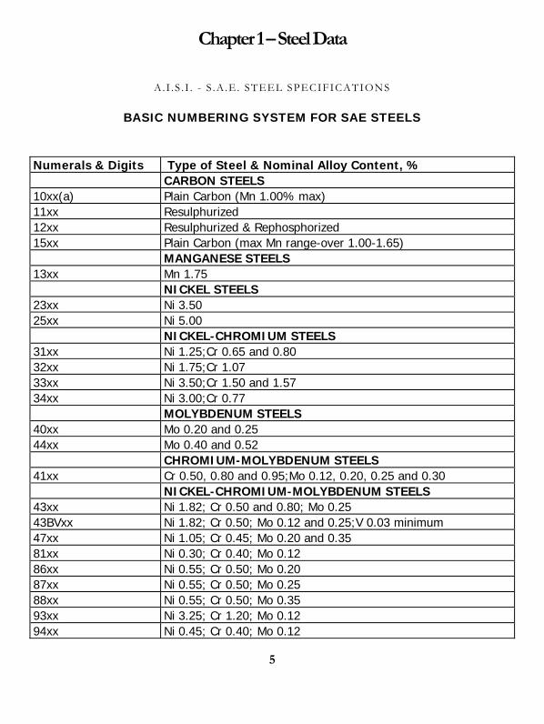
BASIC NUMBERING SYSTEM FOR SAE STEELS
Numerals & Digits Type of Steel & Nominal Alloy Content, % CARBON STEELS 10xx(a) Plain Carbon (Mn 1.00% max) 11xx Resulphurized 12xx Resulphurized & Rephosphorized 15xx Plain Carbon (max Mn range-over 1.00-1.65) MANGANESE STEELS 13xx Mn 1.75 NICKEL STEELS 23xx Ni 3.50 25xx Ni 5.00 NICKEL-CHROMIUM STEELS 31xx Ni 1.25;Cr 0.65 and 0.80 32xx Ni 1.75;Cr 1.07 33xx Ni 3.50;Cr 1.50 and 1.57 34xx Ni 3.00;Cr 0.77 MOLYBDENUM STEELS 40xx Mo 0.20 and 0.25 44xx Mo 0.40 and 0.52 CHROMIUM-MOLYBDENUM STEELS 41xx Cr 0.50, 0.80 and 0.95;Mo 0.12, 0.20, 0.25 and 0.30 NICKEL-CHROMIUM-MOLYBDENUM STEELS 43xx Ni 1.82; Cr 0.50 and 0.80; Mo 0.25 43BVxx Ni 1.82; Cr 0.50; Mo 0.12 and 0.25;V 0.03 minimum 47xx Ni 1.05; Cr 0.45; Mo 0.20 and 0.35 81xx Ni 0.30; Cr 0.40; Mo 0.12 86xx Ni 0.55; Cr 0.50; Mo 0.20 87xx Ni 0.55; Cr 0.50; Mo 0.25 88xx Ni 0.55; Cr 0.50; Mo 0.35 93xx Ni 3.25; Cr 1.20; Mo 0.12 94xx Ni 0.45; Cr 0.40; Mo 0.12
6
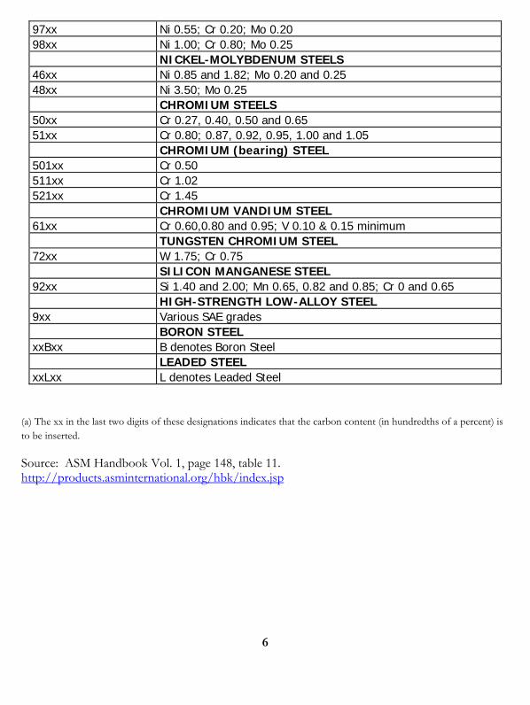
97xx Ni 0.55; Cr 0.20; Mo 0.20 98xx Ni 1.00; Cr 0.80; Mo 0.25 NICKEL-MOLYBDENUM STEELS 46xx Ni 0.85 and 1.82; Mo 0.20 and 0.25 48xx Ni 3.50; Mo 0.25 CHROMIUM STEELS 50xx Cr 0.27, 0.40, 0.50 and 0.65 51xx Cr 0.80; 0.87, 0.92, 0.95, 1.00 and 1.05 CHROMIUM (bearing) STEEL 501xx Cr 0.50 511xx Cr 1.02 521xx Cr 1.45 CHROMIUM VANDIUM STEEL 61xx Cr 0.60,0.80 and 0.95; V 0.10 & 0.15 minimum TUNGSTEN CHROMIUM STEEL 72xx W 1.75; Cr 0.75 SILICON MANGANESE STEEL 92xx Si 1.40 and 2.00; Mn 0.65, 0.82 and 0.85; Cr 0 and 0.65 HIGH-STRENGTH LOW-ALLOY STEEL 9xx Various SAE grades BORON STEEL xxBxx B denotes Boron Steel LEADED STEEL xxLxx L denotes Leaded Steel
(a) The xx in the last two digits of these designations indicates that the carbon content (in hundredths of a percent) is to be inserted.
Source: ASM Handbook Vol. 1, page 148, table 11. http://products.asminternational.org/hbk/index.jsp
7
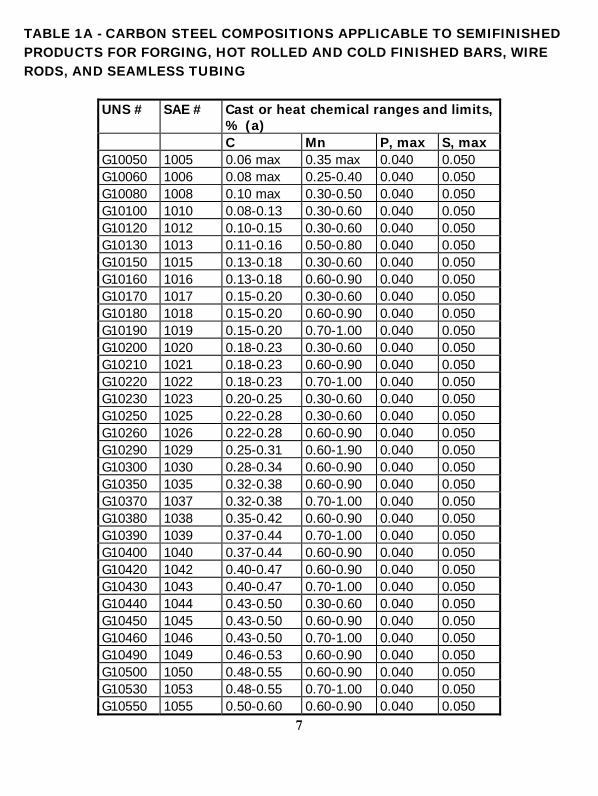
TABLE 1A - CARBON STEEL COMPOSITIONS APPLICABLE TO SEMIFINISHED PRODUCTS FOR FORGING, HOT ROLLED AND COLD FINISHED BARS, WIRE RODS, AND SEAMLESS TUBING
UNS # SAE # Cast or heat chemical ranges and limits, % (a)
C Mn P, max S, max G10050 1005 0.06 max 0.35 max 0.040 0.050 G10060 1006 0.08 max 0.25-0.40 0.040 0.050 G10080 1008 0.10 max 0.30-0.50 0.040 0.050 G10100 1010 0.08-0.13 0.30-0.60 0.040 0.050 G10120 1012 0.10-0.15 0.30-0.60 0.040 0.050 G10130 1013 0.11-0.16 0.50-0.80 0.040 0.050 G10150 1015 0.13-0.18 0.30-0.60 0.040 0.050 G10160 1016 0.13-0.18 0.60-0.90 0.040 0.050 G10170 1017 0.15-0.20 0.30-0.60 0.040 0.050 G10180 1018 0.15-0.20 0.60-0.90 0.040 0.050 G10190 1019 0.15-0.20 0.70-1.00 0.040 0.050 G10200 1020 0.18-0.23 0.30-0.60 0.040 0.050 G10210 1021 0.18-0.23 0.60-0.90 0.040 0.050 G10220 1022 0.18-0.23 0.70-1.00 0.040 0.050 G10230 1023 0.20-0.25 0.30-0.60 0.040 0.050 G10250 1025 0.22-0.28 0.30-0.60 0.040 0.050 G10260 1026 0.22-0.28 0.60-0.90 0.040 0.050 G10290 1029 0.25-0.31 0.60-1.90 0.040 0.050 G10300 1030 0.28-0.34 0.60-0.90 0.040 0.050 G10350 1035 0.32-0.38 0.60-0.90 0.040 0.050 G10370 1037 0.32-0.38 0.70-1.00 0.040 0.050 G10380 1038 0.35-0.42 0.60-0.90 0.040 0.050 G10390 1039 0.37-0.44 0.70-1.00 0.040 0.050 G10400 1040 0.37-0.44 0.60-0.90 0.040 0.050 G10420 1042 0.40-0.47 0.60-0.90 0.040 0.050 G10430 1043 0.40-0.47 0.70-1.00 0.040 0.050 G10440 1044 0.43-0.50 0.30-0.60 0.040 0.050 G10450 1045 0.43-0.50 0.60-0.90 0.040 0.050 G10460 1046 0.43-0.50 0.70-1.00 0.040 0.050 G10490 1049 0.46-0.53 0.60-0.90 0.040 0.050 G10500 1050 0.48-0.55 0.60-0.90 0.040 0.050 G10530 1053 0.48-0.55 0.70-1.00 0.040 0.050 G10550 1055 0.50-0.60 0.60-0.90 0.040 0.050
8
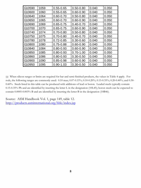
G10590 1059 0.55-0.65 0.50-0.80 0.040 0.050 G10600 1060 0.55-0.65 0.60-0.90 0.040 0.050 G10640 1064 0.60-0.70 0.50-0.80 0.040 0.050 G10650 1065 0.60-0.70 0.60-0.90 0.040 0.050 G10690 1069 0.65-0.75 0.40-0.70 0.040 0.050 G10700 1070 0.65-0.75 0.60-0.90 0.040 0.050 G10740 1074 0.70-0.80 0.50-0.80 0.040 0.050 G10750 1075 0.70-0.80 0.40-0.70 0.040 0.050 G10780 1078 0.72-0.85 0.30-0.60 0.040 0.050 G10800 1080 0.75-0.88 0.60-0.90 0.040 0.050 G10840 1084 0.80-0.93 0.60-0.90 0.040 0.050 G10850 1085 0.80-0.93 0.70-1.00 0.040 0.050 G10860 1086 0.80-0.93 0.30-0.50 0.040 0.050 G10900 1090 0.85-0.98 0.60-0.90 0.040 0.050 G10950 1095 0.90-1.03 0.30-0.50 0.040 0.050
(a) When silicon ranges or limits are required for bar and semi-finished products, the values in Table 4 apply. For rods, the following ranges are commonly used: 0.10 max; 0.07-0.15%; 0.10-0.20%; 0.15-0.35%; 0.20-0.40%; and 0.30-0.60%. Steels listed in this table can be produced with additions of lead or boron. Leaded steels typically contain 0.15-0.35% Pb and are identified by inserting the letter L in the designation (10L45); boron steels can be expected to contain 0.0005-0.003% B and are identified by inserting the letter B in the designation (10B46).
Source: ASM Handbook Vol. 1, page 149, table 12. http://products.asminternational.org/hbk/index.jsp

9
TABLE 1B - CARBON STEEL COMPOSITONS APPLICABLE ONLY TO STRUCTURAL SHAPES, PLATES, STRIP, SHEETS AND WELDED TUBING
UNS # SAE - Cast or heat chemical ranges and limits, % (a)
AISI # C Mn P, max S, max
G10060 1006 0.80 max 0.45 max 0.040 0.050
G10080 1008 0.10 max 0.50 max 0.040 0.050
G10090 1009 0.15 max 0.60 max 0.040 0.050
G10100 1010 0.80-0.13 0.30-0.60 0.040 0.050
G10120 1012 0.10-0.15 0.30-0.60 0.040 0.050
G10150 1015 0.12-0.18 0.30-0.60 0.040 0.050
G10160 1016 0.12-0.18 0.60-0.90 0.040 0.050
G10170 1017 0.14-0.20 0.30-0.60 0.040 0.050
G10180 1018 0.14-0.20 0.60-0.90 0.040 0.050
G10190 1019 0.14-0.20 0.70-1.00 0.040 0.050
G10200 1020 0.17-0.23 0.30-0.60 0.040 0.050
G10210 1021 0.17-0.23 0.60-0.90 0.040 0.050
G10220 1022 0.17-0.23 0.70-1.00 0.040 0.050
G10230 1023 0.19-0.25 0.30-0.60 0.040 0.050
G10250 1025 0.22-0.28 0.30-0.60 0.040 0.050
G10260 1026 0.22-0.28 0.60-0.90 0.040 0.050
G10300 1030 0.27-0.34 0.60-0.90 0.040 0.050
G10330 1033 0.29-0.36 0.70-1.00 0.040 0.050
G10350 1035 0.31-0.38 0.60-0.90 0.040 0.050
G10370 1037 0.31-0.38 0.70-1.00 0.040 0.050
G10380 1038 0.34-0.42 0.60-0.90 0.040 0.050
G10390 1039 0.36-0.44 0.70-1.00 0.040 0.050
G10400 1040 0.36-0.44 0.60-0.90 0.040 0.050
G10420 1042 0.39-0.47 0.60-0.90 0.040 0.050
G10430 1043 0.39-0.47 0.70-1.00 0.040 0.050
10
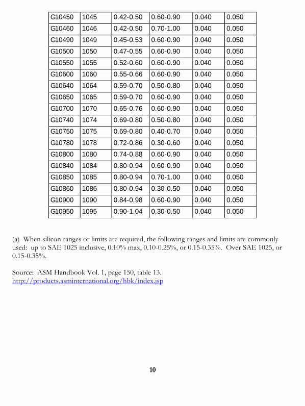
G10450 1045 0.42-0.50 0.60-0.90 0.040 0.050
G10460 1046 0.42-0.50 0.70-1.00 0.040 0.050
G10490 1049 0.45-0.53 0.60-0.90 0.040 0.050
G10500 1050 0.47-0.55 0.60-0.90 0.040 0.050
G10550 1055 0.52-0.60 0.60-0.90 0.040 0.050
G10600 1060 0.55-0.66 0.60-0.90 0.040 0.050
G10640 1064 0.59-0.70 0.50-0.80 0.040 0.050
G10650 1065 0.59-0.70 0.60-0.90 0.040 0.050
G10700 1070 0.65-0.76 0.60-0.90 0.040 0.050
G10740 1074 0.69-0.80 0.50-0.80 0.040 0.050
G10750 1075 0.69-0.80 0.40-0.70 0.040 0.050
G10780 1078 0.72-0.86 0.30-0.60 0.040 0.050
G10800 1080 0.74-0.88 0.60-0.90 0.040 0.050
G10840 1084 0.80-0.94 0.60-0.90 0.040 0.050
G10850 1085 0.80-0.94 0.70-1.00 0.040 0.050
G10860 1086 0.80-0.94 0.30-0.50 0.040 0.050
G10900 1090 0.84-0.98 0.60-0.90 0.040 0.050
G10950 1095 0.90-1.04 0.30-0.50 0.040 0.050
(a) When silicon ranges or limits are required, the following ranges and limits are commonly used: up to SAE 1025 inclusive, 0.10% max, 0.10-0.25%, or 0.15-0.35%. Over SAE 1025, or 0.15-0.35%.
Source: ASM Handbook Vol. 1, page 150, table 13. http://products.asminternational.org/hbk/index.jsp
11
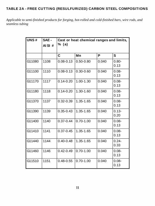
TABLE 2A - FREE CUTTING (RESULFURIZED) CARBON STEEL COMPOSITIONS
Applicable to semi-finished products for forging, hot-rolled and cold-finished bars, wire rods, and seamless tubing
UNS # SAE -
AISI #
Cast or heat chemical ranges and limits, % (a)
C Mn P S
G11080 1108 0.08-0.13 0.50-0.80 0.040 0.80-0.13
G11100 1110 0.08-0.13 0.30-0.60 0.040 0.08-0.13
G11170 1117 0.14-0.20 1.00-1.30 0.040 0.08-0.13
G11180 1118 0.14-0.20 1.30-1.60 0.040 0.08-0.13
G11370 1137 0.32-0.39 1.35-1.65 0.040 0.08-0.13
G11390 1139 0.35-0.43 1.35-1.65 0.040 0.13-0.20
G11400 1140 0.37-0.44 0.70-1.00 0.040 0.08-0.13
G11410 1141 0.37-0.45 1.35-1.65 0.040 0.08-0.13
G11440 1144 0.40-0.48 1.35-1.65 0.040 0.24-0.33
G11460 1146 0.42-0.49 0.70-1.00 0.040 0.08-0.13
G11510 1151 0.48-0.55 0.70-1.00 0.040 0.08-0.13
12
(a) When lead ranges or limits are required, or when silicon ranges or limits are required for bars or semi-finished products, the values in Table 4 apply. For rods, the following ranges and limits for silicon are commonly used: up to SAE 1110 inclusive, 0.10% max; SAE 1117 and over, 0.10% max, 0.10-0.20% or 0.15-0.35%.
Source: ASM Handbook Vol. 1, page 150, table 15. http://products.asminternational.org/hbk/index.jsp
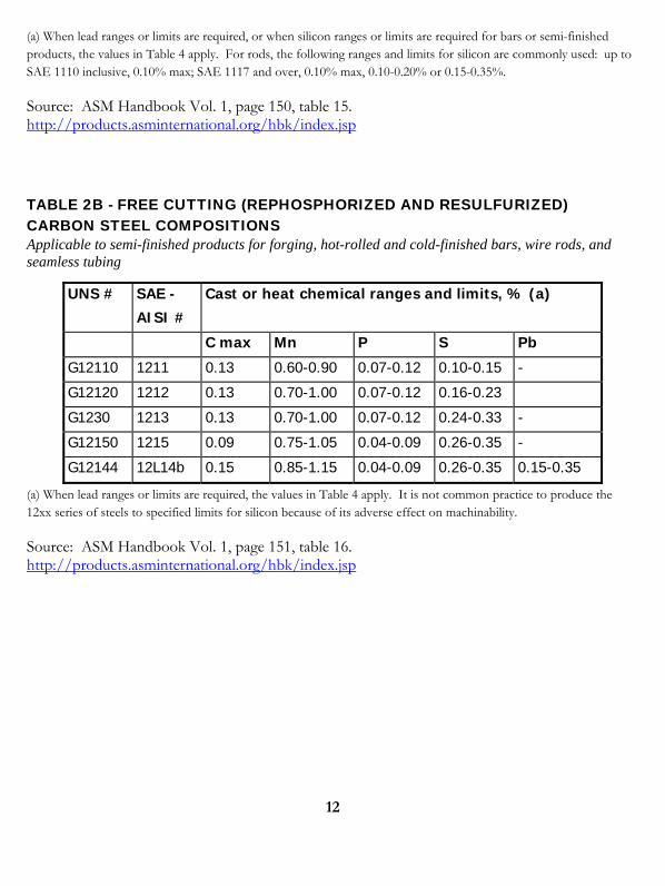
TABLE 2B - FREE CUTTING (REPHOSPHORIZED AND RESULFURIZED) CARBON STEEL COMPOSITIONS Applicable to semi-finished products for forging, hot-rolled and cold-finished bars, wire rods, and seamless tubing
UNS # SAE -
AISI #
Cast or heat chemical ranges and limits, % (a)
C max Mn P S Pb
G12110 1211 0.13 0.60-0.90 0.07-0.12 0.10-0.15 -
G12120 1212 0.13 0.70-1.00 0.07-0.12 0.16-0.23
G1230 1213 0.13 0.70-1.00 0.07-0.12 0.24-0.33 -
G12150 1215 0.09 0.75-1.05 0.04-0.09 0.26-0.35 -
G12144 12L14b 0.15 0.85-1.15 0.04-0.09 0.26-0.35 0.15-0.35
(a) When lead ranges or limits are required, the values in Table 4 apply. It is not common practice to produce the 12xx series of steels to specified limits for silicon because of its adverse effect on machinability.
Source: ASM Handbook Vol. 1, page 151, table 16. http://products.asminternational.org/hbk/index.jsp
13
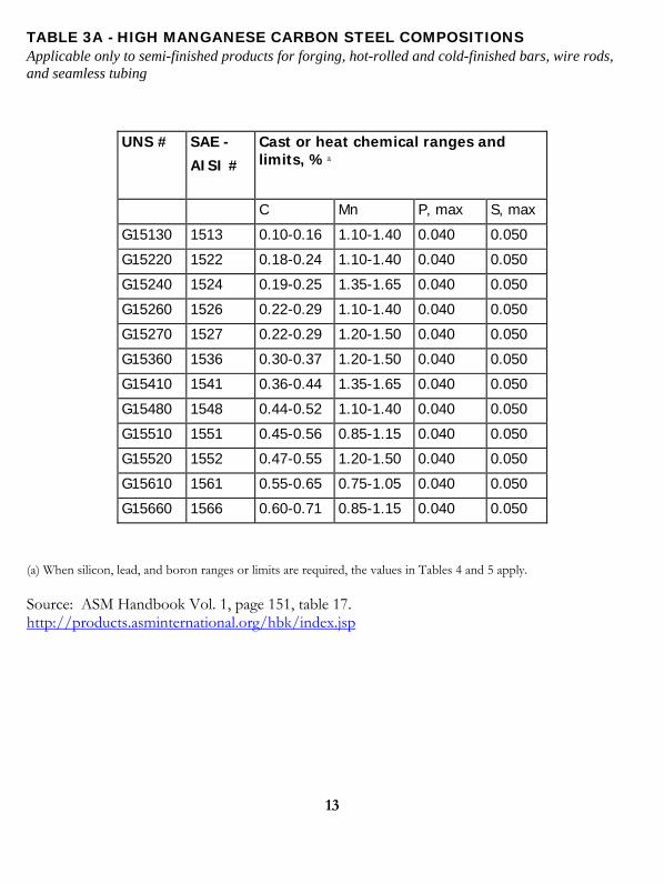
TABLE 3A - HIGH MANGANESE CARBON STEEL COMPOSITIONS Applicable only to semi-finished products for forging, hot-rolled and cold-finished bars, wire rods, and seamless tubing
UNS # SAE -
AISI #
Cast or heat chemical ranges and limits, %a
C Mn P, max S, max
G15130 1513 0.10-0.16 1.10-1.40 0.040 0.050
G15220 1522 0.18-0.24 1.10-1.40 0.040 0.050
G15240 1524 0.19-0.25 1.35-1.65 0.040 0.050
G15260 1526 0.22-0.29 1.10-1.40 0.040 0.050
G15270 1527 0.22-0.29 1.20-1.50 0.040 0.050
G15360 1536 0.30-0.37 1.20-1.50 0.040 0.050
G15410 1541 0.36-0.44 1.35-1.65 0.040 0.050
G15480 1548 0.44-0.52 1.10-1.40 0.040 0.050
G15510 1551 0.45-0.56 0.85-1.15 0.040 0.050
G15520 1552 0.47-0.55 1.20-1.50 0.040 0.050
G15610 1561 0.55-0.65 0.75-1.05 0.040 0.050
G15660 1566 0.60-0.71 0.85-1.15 0.040 0.050
(a) When silicon, lead, and boron ranges or limits are required, the values in Tables 4 and 5 apply.
Source: ASM Handbook Vol. 1, page 151, table 17. http://products.asminternational.org/hbk/index.jsp
14
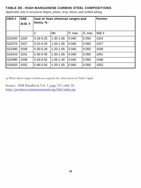
TABLE 3B - HIGH MANGANESE CARBON STEEL COMPOSITIONS Applicable only to structural shapes, plates, strip, sheets, and welded tubing.
UNS # SAE -
AISI #
Cast or heat chemical ranges and limits, %a
Former
C Mn P, max S, max SAE #
G15240 1524 0.18-0.25 1.30-1.65 0.040 0.050 1024
G15270 1527 0.22-0.29 1.20-1.55 0.040 0.050 1027
G15360 1536 0.30-0.28 1.20-1.55 0.040 0.050 1036
G15410 1541 0.36-0.45 1.30-1.65 0.040 0.050 1041
G15480 1548 0.43-0.52 1.05-1.40 0.040 0.050 1048
G15520 1552 0.46-0.55 1.20-1.55 0.040 0.050 1052
(a) When silicon ranges or limits are required, the values shown in Table 5 apply.
Source: ASM Handbook Vol. 1, page 151, table 18. http://products.asminternational.org/hbk/index.jsp
15
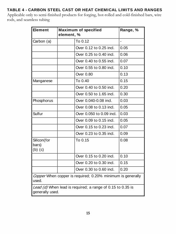
TABLE 4 - CARBON STEEL CAST OR HEAT CHEMICAL LIMITS AND RANGES Applicable only to semi-finished products for forging, hot-rolled and cold-finished bars, wire rods, and seamless tubing
Element Maximum of specified element, %
Range, %
Carbon (a) To 0.12 -
Over 0.12 to 0.25 incl. 0.05
Over 0.25 to 0.40 incl. 0.06
Over 0.40 to 0.55 incl. 0.07
Over 0.55 to 0.80 incl. 0.10
Over 0.80 0.13
Manganese To 0.40 0.15
Over 0.40 to 0.50 incl. 0.20
Over 0.50 to 1.65 incl. 0.30
Phosphorus Over 0.040-0.08 incl. 0.03
Over 0.08 to 0.13 incl. 0.05
Sulfur Over 0.050 to 0.09 incl. 0.03
Over 0.09 to 0.15 incl. 0.05
Over 0.15 to 0.23 incl. 0.07
Over 0.23 to 0.35 incl. 0.09
Silicon(for bars) (b) (c)
To 0.15 0.08
Over 0.15 to 0.20 incl. 0.10
Over 0.20 to 0.30 incl. 0.15
Over 0.30 to 0.60 incl. 0.20
Copper When copper is required; 0.20% minimum is generally used.
Lead (d) When lead is required; a range of 0.15 to 0.35 is generally used.

16
Note: Boron-treated fine grain steels are produced to a range of 0.005-0.003% B. Incl, inclusive. (a) The carbon ranges shown customarily apply when the specified maximum limit for manganese does not exceed 1.10%. When the maximum manganese limit exceeds 1.10%, it is customary to add 0.01 to the carbon range shown. (b) It is not a common practice to produce a re-phosphorized and re-sulferized carbon steel to specified limits for silicon because of its adverse effect on machinablility. (c)When silicon is required for rods the following ranges and limits are commonly used: 0.10 max; 0.07-0.15, 0.10-0.20, 0.15-0.35, 0.20-0.40, or 0.30-0.60. (d) Lead is reported only as a range of 0.15-0.35% because it is usually added to the mold or ladle stream as the steel is poured.
Source: ASM Handbook Vol. 1, page 141, table 1. http://products.asminternational.org/hbk/index.jsp
17
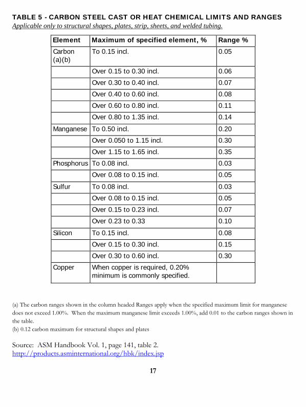
TABLE 5 - CARBON STEEL CAST OR HEAT CHEMICAL LIMITS AND RANGES Applicable only to structural shapes, plates, strip, sheets, and welded tubing.
Element Maximum of specified element, % Range %
Carbon (a)(b)
To 0.15 incl. 0.05
Over 0.15 to 0.30 incl. 0.06
Over 0.30 to 0.40 incl. 0.07
Over 0.40 to 0.60 incl. 0.08
Over 0.60 to 0.80 incl. 0.11
Over 0.80 to 1.35 incl. 0.14
Manganese To 0.50 incl. 0.20
Over 0.050 to 1.15 incl. 0.30
Over 1.15 to 1.65 incl. 0.35
Phosphorus To 0.08 incl. 0.03
Over 0.08 to 0.15 incl. 0.05
Sulfur To 0.08 incl. 0.03
Over 0.08 to 0.15 incl. 0.05
Over 0.15 to 0.23 incl. 0.07
Over 0.23 to 0.33 0.10
Silicon To 0.15 incl. 0.08
Over 0.15 to 0.30 incl. 0.15
Over 0.30 to 0.60 incl. 0.30
Copper When copper is required, 0.20% minimum is commonly specified.
(a) The carbon ranges shown in the column headed Ranges apply when the specified maximum limit for manganese does not exceed 1.00%. When the maximum manganese limit exceeds 1.00%, add 0.01 to the carbon ranges shown in the table. (b) 0.12 carbon maximum for structural shapes and plates
Source: ASM Handbook Vol. 1, page 141, table 2. http://products.asminternational.org/hbk/index.jsp

18
TABLE 1A - LOW-ALLOY STEEL COMPOSITIONS APPLICABLE TO BILLETS, BLOOMS, SLABS, AND HOT-ROLLED AND COLD-FINISHED BARS Slightly wider ranges of compositions apply to plates
Ladle Chemical Composition Limits, % UNS # SAE # Corresponding
C Mn P S Si Ni Cr Mo V AISI #
G13300 1330 0.28-0.33 1.60-1.90 0.035 0.040 0.15-0.35 - - - - 1330 G13350 1335 0.33-0.38 1.60-1.90 0.035 0.040 0.15-0.35 - - - - 1335 G13400 1340 0.38-0.43 1.60-1.90 0.035 0.040 0.15-0.35 - - - - 1340 G13450 1345 0.43-0.48 1.60-1.90 0.035 0.040 0.15-0.35 - - - - 1345 G40230 4023 0.20-0.25 0.70-0.90 0.035 0.040 0.15-0.35 - - - - 4023 G40240 4024 0.20-0.25 0.70-0.90 0.035 0.035-
0.050 0.15-0.35 - - 0.20-0.30 - 4024
G40270 4027 0.25-0.30 0.70-0.90 0.035 0.040 0.15-0.35 - - 0.20-0.30 - 4027 G40280 4028 0.25-0.30 0.70-0.90 0.035 0.035-
0.050 0.15-0.35 - - 0.20-0.30 - 4028
G40320 4032 0.30-0.35 0.70-0.90 0.035 0.040 0.15-0.35 - - 0.20-0.30 - - G40370 4037 0.35-0.40 0.70-0.90 0.035 0.040 0.15-0.35 - - 0.20-0.30 - 4037 G40420 4042 0.40-0.45 0.70-0.90 0.035 0.040 0.15-0.35 - - 0.20-0.30 - - G40470 4047 0.45-0.50 0.70-0.90 0.035 0.040 0.15-0.35 - - 0.20-0.30 - 4047 G41180 4118 0.18-0.23 0.70-0.90 0.035 0.040 0.15-0.35 - 0.40-0.60 0.08-0.15 - 4118 G41300 4130 0.28-0.33 0.40-0.60 0.035 0.040 0.15-0.35 - 0.80-1.10 0.15-0.25 - 4130 G41350 4135 0.33-0.38 0.70-0.90 0.035 0.040 0.15-0.35 - 0.80-1.10 0.15-0.25 - - G41370 4137 0.35-0.40 0.70-0.90 0.035 0.040 0.15-0.35 - 0.80-1.10 0.15-0.25 - 4137 G41400 4140 0.38-0.43 0.75-1.00 0.035 0.040 0.15-0.35 - 0.80-1.10 0.15-0.25 - 4140 G41420 4142 0.40-0.45 0.75-1.00 0.035 0.040 0.15-0.35 - 0.80-1.10 0.15-0.25 - 4142 G41450 4145 0.41-0.48 0.75-1.00 0.035 0.040 0.15-0.35 - 0.80-1.10 0.15-0.25 - 4145 G41470 4147 0.45-0.50 0.75-1.00 0.035 0.040 0.15-0.35 - 0.80-1.10 0.15-0.25 - 4147 G41500 4150 0.48-0.53 0.75-1.00 0.035 0.040 0.15-0.35 - 0.80-1.10 0.15-0.25 - 4150 G41610 4161 0.56-0.64 0.75-1.00 0.035 0.040 0.15-0.35 - 0.70-0.90 0.25-0.35 - 4161 G43200 4320 0.17-0.22 0.45-0.65 0.035 0.040 0.15-0.35 1.65-2.00 0.40-0.60 0.20-0.30 - 4320 G43400 4340 0.38-0.43 0.60-0.80 0.035 0.040 0.15-0.35 1.65-2.00 0.70-0.90 0.20-0.30 - 4340 G43406 E4340b 0.38-0.43 0.65-0.85 0.025 0.025 0.15-0.35 1.65-2.00 0.70-0.90 0.20-0.30 - E4340
G44220 4422 0.20-0.25 0.70-0.90 0.035 0.040 0.15-0.35 - - 0.35-0.45 - - G44270 4427 0.24-0.29 0.70-0.90 0.035 0.040 0.15-0.35 - - 0.35-0.45 - - G46150 4615 0.13-0.18 0.45-0.65 0.035 0.040 0.15-0.25 1.65-2.00 - 0.20-0.30 - 4615 G46170 4617 0.15-0.20 0.45-0.65 0.035 0.040 0.15-0.35 1.65-2.00 - 0.20-0.30 - - G46200 4620 0.17-0.22 0.45-0.65 0.035 0.040 0.15-0.35 1.65-2.00 - 0.20-0.30 - 4620 G46260 4626 0.24-0.29 0.45-0.65 0.035 0.04
max 0.15-0.35 0.70-1.00 - 0.15-0.25 - -
G47180 4718 0.16-0.21 0.70-0.90 - - - 0.90-1.20 0.35-0.55 0.30-0.40 - 4718 G47200 4720 0.17-0.22 0.50-0.70 0.035 0.040 0.15-0.35 0.90-1.20 0.35-0.55 0.15-0.25 - 4720 G48150 4815 0.13-0.18 0.40-0.60 0.035 0.040 0.15-0.35 3.25-3.75 - 0.20-0.30 - 4815 G48170 4817 0.15-0.20 0.40-0.60 0.035 0.040 0.15-0.35 3.25-3.75 - 0.20-0.30 - 4817 G48200 4820 0.18-0.23 0.50-0.70 0.035 0.040 0.15-0.35 3.25-3.75 - 0.20-0.30 - 4820 G50401 50B40c 0.38-0.43 0.75-1.00 0.035 0.040 0.15-0.35 - 0.40-0.60 - - -
G50441 50B44c 0.43-0.48 0.75-1.00 0.035 0.040 0.15-0.35 - 0.40-0.60 - - 50B44
G50460 5046 0.43-0.48 0.75-1.00 0.035 0.040 0.15-0.35 - 0.20-0.35 - - - G50461 50B46c 0.44-0.49 0.75-1.00 0.035 0.040 0.15-0.35 - 0.20-0.35 - - 50B46
G50501 50B50c 0.48-0.53 0.75-1.00 0.035 0.040 0.15-0.35 - 0.40-0.60 - - 50B50
G50600 5060 0.56-0.64 0.75-1.00 0.035 0.040 0.15-0.35 - 0.40-0.60 - - - G50601 50B60c 0.56-0.64 0.75-1.00 0.035 0.040 0.15-0.35 - 0.40-0.60 - - 50B60
G51150 5115 0.13-0.18 0.70-0.90 0.035 0.040 0.15-0.35 - 0.70-0.90 - - - G51170 5117 0.15-0.20 0.70-0.90 0.04 0.040 0.15-0.35 - 0.70.90 - - 5117
19
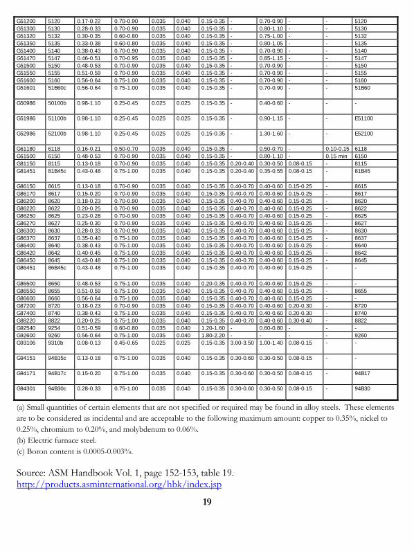
G51200 5120 0.17-0.22 0.70-0.90 0.035 0.040 0.15-0.35 - 0.70-0.90 - - 5120 G51300 5130 0.28-0.33 0.70-0.90 0.035 0.040 0.15-0.35 - 0.80-1.10 - - 5130 G51320 5132 0.30-0.35 0.60-0.80 0.035 0.040 0.15-0.35 - 0.75-1.00 - - 5132 G51350 5135 0.33-0.38 0.60-0.80 0.035 0.040 0.15-0.35 - 0.80-1.05 - - 5135 G51400 5140 0.38-0.43 0.70-0.90 0.035 0.040 0.15-0.35 - 0.70-0.90 - - 5140 G51470 5147 0.46-0.51 0.70-0.95 0.035 0.040 0.15-0.35 - 0.85-1.15 - - 5147 G51500 5150 0.48-0.53 0.70-0.90 0.035 0.040 0.15-0.35 - 0.70-0.90 - - 5150 G51550 5155 0.51-0.59 0.70-0.90 0.035 0.040 0.15-0.35 - 0.70-0.90 - - 5155 G51600 5160 0.56-0.64 0.75-1.00 0.035 0.040 0.15-0.35 - 0.70-0.90 - - 5160 G51601 51B60c 0.56-0.64 0.75-1.00 0.035 0.040 0.15-0.35 - 0.70-0.90 - - 51B60
G50986 50100b 0.98-1.10 0.25-0.45 0.025 0.025 0.15-0.35 - 0.40-0.60 - - -
G51986 51100b 0.98-1.10 0.25-0.45 0.025 0.025 0.15-0.35 - 0.90-1.15 - - E51100
G52986 52100b 0.98-1.10 0.25-0.45 0.025 0.025 0.15-0.35 - 1.30-1.60 - - E52100
G61180 6118 0.16-0.21 0.50-0.70 0.035 0.040 0.15-0.35 - 0.50-0.70 - 0.10-0.15 6118 G61500 6150 0.48-0.53 0.70-0.90 0.035 0.040 0.15-0.35 - 0.80-1.10 - 0.15 min 6150 G81150 8115 0.13-0.18 0.70-0.90 0.035 0.040 0.15-0.35 0.20-0.40 0.30-0.50 0.08-0.15 - 8115 G81451 81B45c 0.43-0.48 0.75-1.00 0.035 0.040 0.15-0.35 0.20-0.40 0.35-0.55 0.08-0.15 - 81B45
G86150 8615 0.13-0.18 0.70-0.90 0.035 0.040 0.15-0.35 0.40-0.70 0.40-0.60 0.15-0.25 - 8615 G86170 8617 0.15-0.20 0.70-0.90 0.035 0.040 0.15-0.35 0.40-0.70 0.40-0.60 0.15-0.25 - 8617 G86200 8620 0.18-0.23 0.70-0.90 0.035 0.040 0.15-0.35 0.40-0.70 0.40-0.60 0.15-0.25 - 8620 G86220 8622 0.20-0.25 0.70-0.90 0.035 0.040 0.15-0.35 0.40-0.70 0.40-0.60 0.15-0.25 - 8622 G86250 8625 0.23-0.28 0.70-0.90 0.035 0.040 0.15-0.35 0.40-0.70 0.40-0.60 0.15-0.25 - 8625 G86270 8627 0.25-0.30 0.70-0.90 0.035 0.040 0.15-0.35 0.40-0.70 0.40-0.60 0.15-0.25 - 8627 G86300 8630 0.28-0.33 0.70-0.90 0.035 0.040 0.15-0.35 0.40-0.70 0.40-0.60 0.15-0.25 - 8630 G86370 8637 0.35-0.40 0.75-1.00 0.035 0.040 0.15-0.35 0.40-0.70 0.40-0.60 0.15-0.25 - 8637 G86400 8640 0.38-0.43 0.75-1.00 0.035 0.040 0.15-0.35 0.40-0.70 0.40-0.60 0.15-0.25 - 8640 G86420 8642 0.40-0.45 0.75-1.00 0.035 0.040 0.15-0.35 0.40-0.70 0.40-0.60 0.15-0.25 - 8642 G86450 8645 0.43-0.48 0.75-1.00 0.035 0.040 0.15-0.35 0.40-0.70 0.40-0.60 0.15-0.25 - 8645 G86451 86B45c 0.43-0.48 0.75-1.00 0.035 0.040 0.15-0.35 0.40-0.70 0.40-0.60 0.15-0.25 - -
G86500 8650 0.48-0.53 0.75-1.00 0.035 0.040 0.20-0.35 0.40-0.70 0.40-0.60 0.15-0.25 - - G86550 8655 0.51-0.59 0.75-1.00 0.035 0.040 0.15-0.35 0.40-0.70 0.40-0.60 0.15-0.25 - 8655 G86600 8660 0.56-0.64 0.75-1.00 0.035 0.040 0.15-0.35 0.40-0.70 0.40-0.60 0.15-0.25 - - G87200 8720 0.18-0.23 0.70-0.90 0.035 0.040 0.15-0.35 0.40-0.70 0.40-0.60 0.20-0.30 - 8720 G87400 8740 0.38-0.43 0.75-1.00 0.035 0.040 0.15-0.35 0.40-0.70 0.40-0.60 0.20-0.30 - 8740 G88220 8822 0.20-0.25 0.75-1.00 0.035 0.040 0.15-0.35 0.40-0.70 0.40-0.60 0.30-0.40 - 8822 G92540 9254 0.51-0.59 0.60-0.80 0.035 0.040 1.20-1.60 - 0.60-0.80 - - - G92600 9260 0.56-0.64 0.75-1.00 0.035 0.040 1.80-2.20 - - - - 9260 G93106 9310b 0.08-0.13 0.45-0.65 0.025 0.025 0.15-0.35 3.00-3.50 1.00-1.40 0.08-0.15 - -
G94151 94B15c 0.13-0.18 0.75-1.00 0.035 0.040 0.15-0.35 0.30-0.60 0.30-0.50 0.08-0.15 - -
G94171 94B17c 0.15-0.20 0.75-1.00 0.035 0.040 0.15-0.35 0.30-0.60 0.30-0.50 0.08-0.15 - 94B17
G94301 94B30c 0.28-0.33 0.75-1.00 0.035 0.040 0.15-0.35 0.30-0.60 0.30-0.50 0.08-0.15 - 94B30
(a) Small quantities of certain elements that are not specified or required may be found in alloy steels. These elements are to be considered as incidental and are acceptable to the following maximum amount: copper to 0.35%, nickel to 0.25%, chromium to 0.20%, and molybdenum to 0.06%. (b) Electric furnace steel. (c) Boron content is 0.0005-0.003%.
Source: ASM Handbook Vol. 1, page 152-153, table 19. http://products.asminternational.org/hbk/index.jsp

20
21
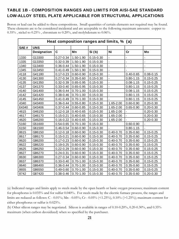
TABLE 1B - COMPOSITION RANGES AND LIMITS FOR AISI-SAE STANDARD LOW-ALLOY STEEL PLATE APPLICABLE FOR STRUCTURAL APPLICATIONS Boron or lead can be added to these compositions. Small quantities of certain elements not required may be found. These elements are to be considered incidental and are acceptable to the following maximum amounts: copper to 0.35% , nickel to 0.25% , chromium to 0.20%, and molybdenum to 0.06%.
Heat composition ranges and limits, % (a) SAE # UNS Designation C Mn Si (b) Ni Cr Mo
1330 G13300 0.27-0.34 1.50-1.90 0.15-0.30 - - - 1335 G13350 0.32-0.39 1.50-1.90 0.15-0.30 - - - 1340 G13400 0.36-0.44 1.50-1.90 0.15-0.30 - - - 1345 G13450 0.41-0.49 1.50-1.90 0.15-0.30 - - - 4118 G41180 0.17-0.23 0.60-0.90 0.15-0.30 - 0.40-0.65 0.08-0.15 4130 G41300 0.27-0.34 0.35-0.60 0.15-0.30 - 0.80-1.15 0.15-0.25 4135 G41350 0.32-0.39 0.65-0.95 0.15-0.30 - 0.08-1.15 0.15-0.25 4137 G41370 0.33-0.40 0.65-0.95 0.15-0.30 - 0.80-1.15 0.15-0.25 4140 G41400 0.36-0.44 0.70-1.00 0.15-0.30 - 0.08-1.15 0.15-0.25 4142 G41420 0.38-0.46 0.70-1.00 0.15-0.30 - 0.80-1.15 0.15-0.25 4145 G41450 0.41-0.49 0.70-1.00 0.15-0.30 - 0.80-1.15 0.15-0.25 4340 G43400 0.36-0.44 0.55-0.80 0.15-0.30 1.65-2.00 0.60-0.90 0.20-0.30 E4340 G43406 0.37-0.44 0.60-0.85 0.15-0.30 1.65-2.00 0.65-0.90 0.20-0.30 4615 G46150 0.12-0.18 0.40-0.65 0.15-0.30 1.65-2.00 - 0.20-0.30 4617 G46170 0.15-0.21 0.40-0.65 0.15-0.30 1.65-2.00 - 0.20-0.30 4620 G46200 0.16-0.22 0.40-0.65 0.15-0.30 1.65-2.00 - 0.20-0.30 5160 G51600 0.54-0.65 0.70-1.00 0.15-0.30 - 0.60-0.90 - 6150 G61500 0.46-0.54 0.60-0.90 0.15-0.30 - 0.80-1.15 - 8615 G86150 0.12-0.18 0.60-0.90 0.15-0.30 0.40-0.70 0.35-0.60 0.15-0.25 8617 G86170 0.15-0.21 0.60-0.90 0.15-0.30 0.40-0.70 0.35-0.60 0.15-0.25 8620 G86200 0.17-0.23 0.60-0.90 0.15-0.30 0.40-0.70 0.35-0.60 0.15-0.25 8622 G86220 0.19-0.25 0.60-0.90 0.15-0.30 0.40-0.70 0.35-0.60 0.15-0.25 8625 G86250 0.22-0.29 0.60-0.90 0.15-0.30 0.40-0.70 0.35-0.60 0.15-0.25 8627 G86270 0.24-0.31 0.60-0.90 0.15-0.30 0.40-0.70 0.35-0.60 0.15-0.25 8630 G86300 0.27-0.34 0.60-0.90 0.15-0.30 0.40-0.70 0.35-0.60 0.15-0.25 8637 G86370 0.33-0.40 0.70-1.00 0.15-0.30 0.40-0.70 0.35-0.60 0.15-0.25 8640 G86400 0.36-0.44 0.70-1.00 0.15-0.30 0.40-0.70 0.35-0.60 0.15-0.25 8655 G86550 0.49-0.60 0.70-1.00 0.15-0.30 0.40-0.70 0.35-0.60 0.15-0.25 8742 G87420 0.38-0.46 0.70-1.00 0.15-0.30 0.40-0.70 0.35-0.60 0.20-0.30
(a) Indicated ranges and limits apply to steels made by the open hearth or basic oxygen processes; maximum content for phosphorus is 0.035% and for sulfur 0.040%. For steels made by the electric furnace process, the ranges and limits are reduced as follows: C - 0.01%; Mn - 0.05%; Cr - 0.05% (<1.25%), 0.10% (>1.25%); maximum content for either phosphorus or sulfur is 0.025%. (b) Other silicon ranges may be negotiated. Silicon is available in ranges of 0.10-0.20%, 0.20-0.30%, and 0.35% maximum (when carbon deoxidized) when so specified by the purchaser.

22
(c) Prefix “E” indicates that the steel is made by the electric furnace process. (d) Contains 0.15% V minimum.
Source: ASM Handbook Vol. 1, page 227, table 3. http://products.asminternational.org/hbk/index.jsp
23
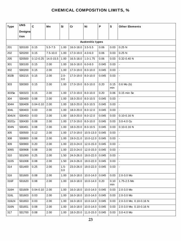
CHEMICAL COMPOSITION LIMITS, %
Type UNS
Designa
tion
C Mn Si Cr Ni P S Other Elements
Austenitic types
201 S20100 0.15 5.5-7.5 1.00 16.0-18.0 3.5-5.5 0.06 0.03 0.25 N
202 S20200 0.15 7.5-10.0 1.00 17.0-19.0 4.0-6.0 0.06 0.03 0.25 N
205 S20500 0.12-0.25 14.0-15.5 1.00 16.5-18.0 1.0-1.75 0.06 0.03 0.32-0.40 N
301 S30100 0.15 2.00 1.00 16.0-18.0 6.0-8.0 0.045 0.03 -
302 S30200 0.15 2.00 1.00 17.0-19.0 8.0-10.0 0.045 0.03 -
302B S30215 0.15 2.00 2.0-3.0
17.0-19.0 8.0-10.0 0.045 0.03 -
303 S30300 0.15 2.00 1.00 17.0-19.0 8.0-10.0 0.20 0.15 min
0.6 Mo (b)
303Se S30323 0.15 2.00 1.00 17.0-19.0 8.0-10.0 0.20 0.06 0.15 min Se
304 S30400 0.08 2.00 1.00 18.0-20.0 8.0-10.5 0.045 0.03 -
304H S30409 0.04-0.10 2.00 1.00 18.0-20.0 8.0-10.5 0.045 0.03 -
304L S30403 0.03 2.00 1.00 18.0-20.0 8.0-12.0 0.045 0.03 -
304LN S30453 0.03 2.00 1.00 18.0-20.0 8.0-12.0 0.045 0.03 0.10-0.16 N
302Cu S30430 0.08 2.00 1.00 17.0-19.0 8.0-10.0 0.045 0.03 3.0-4.0 Cu
304N S30451 0.08 2.00 1.00 18.0-20.0 8.0-10.5 0.045 0.03 0.10-0.16 N
305 S30500 0.12 2.00 1.00 17.0-19.0 10.5-13.0 0.045 0.03 -
308 S30800 0.08 2.00 1.00 19.0-21.0 10.0-12.0 0.045 0.03 -
309 S30900 0.20 2.00 1.00 22.0-24.0 12.0-15.0 0.045 0.03 -
309S S30908 0.08 2.00 1.00 22.0-24.0 12.0-15.0 0.045 0.03 -
310 S31000 0.25 2.00 1.50 24.0-26.0 19.0-22.0 0.045 0.03 -
310S S31008 0.08 2.00 1.50 24.0-26.0 19.0-22.0 0.045 0.03 -
314 S31400 0.25 2.00 1.5-3.0
23.0-26.0 19.0-22.0 0.045 0.03 -
316 S31600 0.08 2.00 1.00 16.0-18.0 10.0-14.0 0.045 0.03 2.0-3.0 Mo
316F S31620 0.08 2.00 1.00 16.0-18.0 10.0-14.0 0.20 0.10 min
1.75-2.5 Mo
316H S31609 0.04-0.10 2.00 1.00 16.0-18.0 10.0-14.0 0.045 0.03 2.0-3.0 Mo
316L S31603 0.03 2.00 1.00 16.0-18.0 10.0-14.0 0.045 0.03 2.0-3.0 Mo
316LN S31653 0.03 2.00 1.00 16.0-18.0 10.0-14.0 0.045 0.03 2.0-3.0 Mo; 0.10-0.16 N
316N S31651 0.08 2.00 1.00 16.0-18.0 10.0-14.0 0.045 0.03 2.0-3.0 Mo; 0.10-0.16 N
317 S31700 0.08 2.00 1.00 18.0-20.0 11.0-15.0 0.045 0.03 3.0-4.0 Mo

24
317L S31703 0.03 2.00 1.00 18.0-20.0 11.0-15.0 0.045 0.03 3.0-4.0 Mo
321 S32100 0.08 2.00 1.00 17.0-19.0 9.0-12.0 0.045 0.03 5 x %C min Ti
321H S32109 0.04-0.10 2.00 1.00 17.0-19.0 9.0-12.0 0.045 0.03 5 x %C min Ti
330 N08330 0.08 2.00 0.75-1.5
17.0-20.0 34.0-37.0 0.04 0.03 -
347 S34700 0.08 2.00 1.00 17.0-19.0 9.0-13.0 0.045 0.03 10 x %C min Nb
347H S34709 0.04-0.10 2.00 1.00 17.0-19.0 9.0-13.0 0.045 0.03 8 x %C min - 1.0 max Nb
348 S34800 0.08 2.00 1.00 17.0-19.0 9.0-13.0 0.045 0.03 0.2 Co; 10 x %C min Nb; 0.10 Ta
348H S34809 0.04-0.10 2.00 1.00 17.0-19.0 9.0-13.0 0.045 0.03 0.2 Co; 8 x %C min - 1.0 max Nb; 0.10 Ta
384 S38400 0.08 2.00 1.00 15.0-17.0 17.0-19.0 0.045 0.03 -
Ferritic types
405 S40500 0.08 1.00 1.00 11.5-14.5 - 0.04 0.03 0.10-0.30 Al
409 S40900 0.08 1.00 1.00 10.5-11.75
0.50 0.045 0.045
6 x %C min - 0.75 max Ti
429 S42900 0.12 1.00 1.00 14.0-16.0 - 0.04 0.03 -
430 S43000 0.12 1.00 1.00 16.0-18.0 - 0.04 0.03 -
430F S43020 0.12 1.25 1.00 16.0-18.0 - 0.06 0.15 min
0.6 Mo (b)
430FSe S43023 0.12 1.25 1.00 16.0-18.0 - 0.06 0.06 0.15 min Se
434 S43400 0.12 1.00 1.00 16.0-18.0 - 0.04 0.03 0.75-1.25 Mo
436 S43600 0.12 1.00 1.00 16.0-18.0 - 0.04 0.03 0.75-1.25 Mo; 5 x %C min - 0.70 max Nb
439 S43035 0.07 1.00 1.00 17.0-19.0 0.50 0.04 0.03 0.15 Al; 12 x %C min - 1.10 Ti
442 S44200 0.20 1.00 1.00 18.0-23.0 - 0.04 0.03 -
444 S44400 0.025 1.00 1.00 17.5-19.5 1.00 0.04 0.03 1.75-2.50 Mo; 0.025 N ; 0.2+4 (%C+ %N) min - 0.8 max (Ti+Nb)
446 S44600 0.20 1.50 1.00 23.0-27.0 - 0.04 0.03 0.25 N
Duplex (ferritic-austenitic) type
329 S32900 0.20 1.00 0.75 23.0-28.0 2.50-5.00 0.04 0.03 1.00-2.00 Mo
Martensitic types
403 S40300 0.15 1.00 0.50 11.5-13.0 - 0.04 0.03 -
410 S41000 0.15 1.00 1.00 11.5-13.5 - 0.04 0.03 -
414 S41400 0.15 1.00 1.00 11.5-13.5 1.25-2.50 0.04 0.03 -
416 S41600 0.15 1.25 1.00 12.0-14.0 - 0.06 0.15 min
0.6 Mo (b)
416Se S41623 0.15 1.25 1.00 12.0-14.0 - 0.06 0.06 0.15 min Se
420 S42000 0.15 min 1.00 1.00 12.0-14.0 - 0.04 0.03 -
420F S42020 0.15 min 1.25 1.00 12.0-14.0 - 0.06 0.15 min
0.6 Mo (b)
422 S42200 0.20-0.25 1.00 0.75 11.5-13.5 0.5-1.0 0.04 0.03 0.75-1.25 Mo; 0.75-1.25 W; 0.15-0.3 V
25
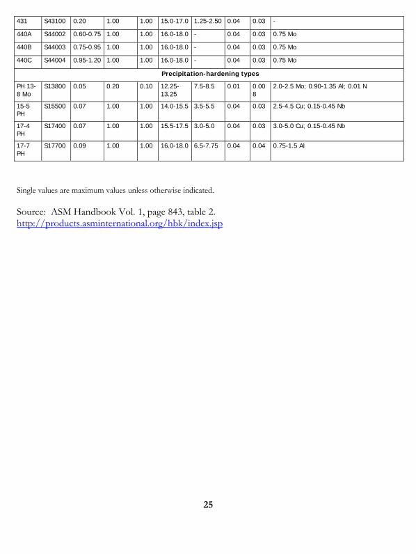
431 S43100 0.20 1.00 1.00 15.0-17.0 1.25-2.50 0.04 0.03 -
440A S44002 0.60-0.75 1.00 1.00 16.0-18.0 - 0.04 0.03 0.75 Mo
440B S44003 0.75-0.95 1.00 1.00 16.0-18.0 - 0.04 0.03 0.75 Mo
440C S44004 0.95-1.20 1.00 1.00 16.0-18.0 - 0.04 0.03 0.75 Mo
Precipitation-hardening types
PH 13-8 Mo
S13800 0.05 0.20 0.10 12.25-13.25
7.5-8.5 0.01 0.008
2.0-2.5 Mo; 0.90-1.35 Al; 0.01 N
15-5 PH
S15500 0.07 1.00 1.00 14.0-15.5 3.5-5.5 0.04 0.03 2.5-4.5 Cu; 0.15-0.45 Nb
17-4 PH
S17400 0.07 1.00 1.00 15.5-17.5 3.0-5.0 0.04 0.03 3.0-5.0 Cu; 0.15-0.45 Nb
17-7 PH
S17700 0.09 1.00 1.00 16.0-18.0 6.5-7.75 0.04 0.04 0.75-1.5 Al
Single values are maximum values unless otherwise indicated.
Source: ASM Handbook Vol. 1, page 843, table 2. http://products.asminternational.org/hbk/index.jsp
26
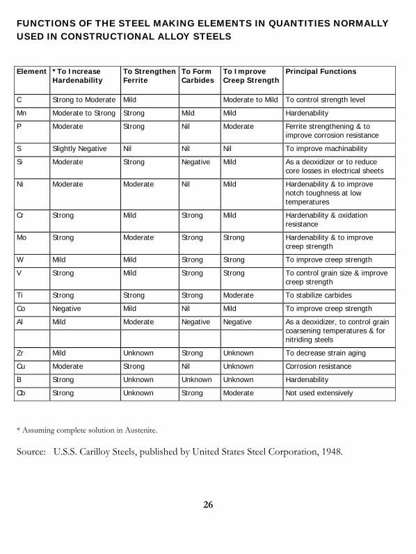
FUNCTIONS OF THE STEEL MAKING ELEMENTS IN QUANTITIES NORMALLY USED IN CONSTRUCTIONAL ALLOY STEELS
Element *To Increase Hardenability
To StrengthenFerrite
To Form Carbides
To Improve Creep Strength
Principal Functions
C Strong to Moderate Mild Moderate to Mild To control strength level
Mn Moderate to Strong Strong Mild Mild Hardenability
P Moderate Strong Nil Moderate Ferrite strengthening & to improve corrosion resistance
S Slightly Negative Nil Nil Nil To improve machinability
Si Moderate Strong Negative Mild As a deoxidizer or to reduce core losses in electrical sheets
Ni Moderate Moderate Nil Mild Hardenability & to improve notch toughness at low temperatures
Cr Strong Mild Strong Mild Hardenability & oxidation resistance
Mo Strong Moderate Strong Strong Hardenability & to improve creep strength
W Mild Mild Strong Strong To improve creep strength
V Strong Mild Strong Strong To control grain size & improve creep strength
Ti Strong Strong Strong Moderate To stabilize carbides
Co Negative Mild Nil Mild To improve creep strength
Al Mild Moderate Negative Negative
As a deoxidizer, to control grain coarsening temperatures & for nitriding steels
Zr Mild Unknown Strong Unknown To decrease strain aging
Cu Moderate Strong Nil Unknown Corrosion resistance
B Strong Unknown Unknown Unknown Hardenability
Cb Strong Unknown Strong Moderate Not used extensively
* Assuming complete solution in Austenite.
Source: U.S.S. Carilloy Steels, published by United States Steel Corporation, 1948.
27
Chapter 2 -Aluminum Metallurgy
ALUMINUM 101
In high-purity form, aluminum is soft and ductile. Most commercial uses, however, require greater strength than pure aluminum affords. This is achieved in aluminum first by the addition of other elements to produce various alloys, which singly or in combination impart strength to the metal. Further strengthening is possible by means which classify the alloys roughly into two categories, non-heat-treatable and heat-treatable.
Non-heat-treatable Alloys- The initial strength of alloys in the group depends upon the hardening effect of elements such as manganese, silicon, iron and magnesium, singly or in various combinations. The non-heat-treatable alloys are usually designated, therefore, in the 1000, 3000, 4000 or 5000 series. Since these alloys are work-hardenable, further strengthening is possible by various degrees of cold-working, denoted by the “H” series of tempers. Alloys containing appreciable amounts of magnesium when supplied in strain-hardened tempers are usually given a final elevated-temperature treatment called stabilizing to insure stability of properties.
Heat-treatable Alloys- The initial strength of alloys in this group is enhanced by the addition of alloying elements such as copper, magnesium, zinc and silicon. Since these elements singly or in various combinations show increasing solid solubility in aluminum with increasing temperature, it is possible to subject them to thermal treatments which will impart pronounced strengthening.
The first step, called heat treatment or solution heat treatment, is an elevated temperature process designed to put the soluble element or elements in solid solution. This is followed by rapid quenching, usually in water, which momentarily “freezes” the structure and for a short time rendering the alloy very workable. It is at this stage that some fabricators retain this more workable structure by storing the alloys at below freezing temperatures until they are ready to form them. At room or elevated temperatures the alloys are not stable after quenching, however, and precipitation of the constituents from the supersaturated solution begins. After a period of several days at room temperature, termed aging or room temperature precipitation, the alloy is considerably stronger. Many alloys approach a stable condition at room temperature, but some alloys, particularly those containing magnesium and silicon or magnesium and zinc, continue to age-harden for long periods of time at room temperature.
28
By heating for a controlled time at slightly elevated temperatures, even further strengthening is possible and properties are stabilized. This process is called artificial aging or precipitation hardening. By the proper combination of solution heat treatment, quenching, cold working and artificial aging, the highest strengths are obtained.
Clad Alloys- The heat-treatable alloys in which copper or zinc are major alloying constituents, are less resistant to corrosive attack than the majority of non-heat-treatable alloys. To increase the corrosion resistance of these alloys in sheet and plate form they are often clad with high-purity aluminum, a low magnesium-silicon alloy, or an alloy containing 1% zinc. The cladding, usually from 2 ½ to 5% of the total thickness on each side, not only protects the composite due to its own inherently excellent corrosion resistance, but also exerts a galvanic effect which further protects the core material.
Special composites may be obtained such as clad non-heat-treatable alloys for extra corrosion protection, for brazing purposes, or for special surface finishes. Some alloys in wire and tubular form are clad for similar reasons and on an experimental basis extrusions also have been clad.

29
EFFECT OF ALLOYING ELEMENTS
1000 Series- Aluminum of 99% or higher purity has many applications, especially in the electrical and chemical fields. These alloys are characterized by excellent corrosion resistance, high thermal and electrical conductivity, low mechanical properties and excellent workability. Moderate increases in strength may be obtained by strain-hardening. Iron and silicon are the major impurities.
2000 Series- Copper is the principal alloying element in this group. These alloys require solution heat-treatment to obtain optimum properties; in the heat treated condition mechanical properties are similar to, and sometimes exceed, those of mild steel. In some instances artificial aging is employed to further increase yield strength, with attendant loss in elongation; its effect on tensile (ultimate) strength is not as great. The alloys in the 2000 series do not have as good corrosion resistance as most other aluminum alloys and under certain conditions they may be subject to intergranular corrosion. Therefore, these alloys in the form of sheet are usually clad with a high purity alloy or a magnesium-silicon alloy of the 6000 series which provides galvanic protection to the core material and thus greatly increases resistance to corrosion. Alloy 2024 is perhaps the best known and most widely used aircraft alloy.
3000 Series- Manganese is the major alloying element of alloys in this group, which are generally non-heat-treatable. Because only a limited percentage of manganese, up to about 1.5%, can be effectively added to aluminum, it is used as a major element in only a few instances. One of these, however, is the popular 3003, which is widely used as a general-purpose alloy for moderate-strength applications requiring good workability.
4000 Series- Major alloying element of this group is silicon, which can be added in sufficient quantities to cause substantial lowering of the melting point without producing brittleness in the resulting alloys. For these reasons aluminum-silicon alloys are used in welding wire and as brazing alloys where lower melting point than that of the parent metal is required. Most alloys in this series are non-heat-treatable, but when used in welding heat-treatable alloys they will pick up some of the alloying constituents of the latter and so respond to heat treatment to a limited extent. The alloys containing appreciable amounts of silicon become dark gray when anodic oxide finishes are applied, and hence are in demand for architectural applications.
5000 Series- Magnesium is one of the most effective and widely used alloying elements for aluminum. When it is used as the major alloying element or with manganese, the result is a moderate to high strength non-heat-treatable alloy. Magnesium is considerably more effective than manganese as a hardener, about 0.8% magnesium being equal to 1.25% manganese, and it can be added in considerably higher quantities. Alloys in this series posses good welding characteristics and good resistance to corrosion in marine atmosphere. However, certain limitations should be placed on the amount of cold work and the safe operating temperatures
30
permissible for the higher magnesium content alloys (over about 3 ½% for operating temperatures above about 150F (66C) to avoid susceptibility to stress corrosion.
6000 Series- Alloys in this group contain silicon and magnesium in approximate proportions to form magnesium silicide, thus making them heat-treatable. Major alloy in this series is 6061, one of the most versatile of the heat-treatable alloys. Though less strong than most of the 2000 or 7000 alloys, the magnesium-silicon (or magnesium-silicide) alloys posses good formability and corrosion resistance, with medium strength. Alloys in the heat-treatable group may be formed in the T4 temper (solution heat-treated but not artificially aged) and then reach full T6 properties by artificial aging.
7000 Series- Zinc is the major alloying element in this group, and when coupled with a smaller percentage of magnesium results in heat-treatable alloys of very high strength. Usually other elements such as copper and chromium are also added in small quantities. Outstanding member of this group is 7075, which is among the highest strength alloys available and is used in air-frame structures and for highly stressed parts.
Source: The Aluminum Association, Aluminum Standards and Data 1974-75. http://www.aluminum.org/
31
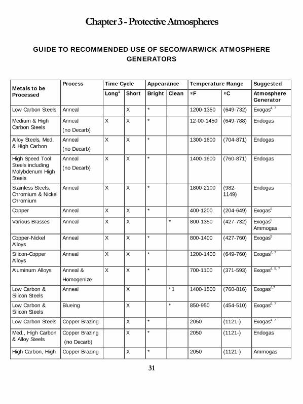
Chapter 3 - Protective Atmospheres
GUIDE TO RECOMMENDED USE OF SECO/WARWICK ATMOSPHERE GENERATORS
Time Cycle Appearance Temperature Range Suggested Metals to be Processed
Process
Long1 Short Bright Clean ºF ºC Atmosphere Generator
Low Carbon Steels Anneal X * 1200-1350 (649-732) Exogas4, 7
Medium & High Carbon Steels
Anneal
(no Decarb)
X X * 12-00-1450 (649-788) Endogas
Alloy Steels, Med. & High Carbon
Anneal
(no Decarb)
X X * 1300-1600 (704-871) Endogas
High Speed Tool Steels including Molybdenum High Steels
Anneal
(no Decarb)
X X * 1400-1600 (760-871) Endogas
Stainless Steels, Chromium & Nickel Chromium
Anneal X X * 1800-2100 (982-1149)
Endogas
Copper Anneal X X * 400-1200 (204-649) Exogas5
Various Brasses Anneal X X * 800-1350 (427-732) Exogas5
Ammogas
Copper-Nickel Alloys
Anneal X X * 800-1400 (427-760) Exogas5
Silicon-Copper Alloys
Anneal X X * 1200-1400 (649-760) Exogas4, 7
Aluminum Alloys Anneal &
Homogenize
X X * 700-1100 (371-593) Exogas4, 5, 7
Low Carbon & Silicon Steels
Anneal X *1 1400-1500 (760-816) Exogas4,7
Low Carbon & Silicon Steels
Blueing X * 850-950 (454-510) Exogas6, 7
Low Carbon Steels Copper Brazing X * 2050 (1121-) Exogas4, 7
Med., High Carbon & Alloy Steels
Copper Brazing
(no Decarb)
X * 2050 (1121-) Endogas
High Carbon, High Copper Brazing X * 2050 (1121-) Ammogas
32
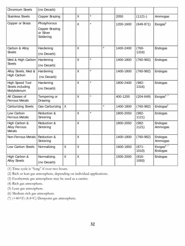
Chromium Steels (no Decarb)
Stainless Steels Copper Brazing X * 2050 (1121-) Ammogas
Copper or Brass Phosphorous
Copper Brazing or Silver Soldering
X * 1200-1600 (649-871) Exogas5
Carbon & Alloy Steels
Hardening
(no Decarb)
X * 1400-2400 (760-1316)
Endogas
Med & High Carbon Steels
Hardening
(no Decarb)
X * 1400-1800 (760-982) Endogas
Alloy Steels, Med & High Carbon
Hardening
(no Decarb)
X * 1400-1800 (760-982) Endogas
High Speed Tool Steels including Molybdenum
Hardening
(no Decarb)
X * 1800-2400 (982-1316)
Endogas
All Classes of Ferrous Metals
Tempering or Drawing
X * 400-1200 (204-649) Exogas4, 7
Carburizing Steels Gas Carburizing X * 1400-1800 (760-982) Endogas3
Low Carbon Ferrous Metals
Reduction & Sintering
X * 1800-2050 (982-1121)
Endogas
High Carbon & Alloy Ferrous Metals
Reduction & Sintering
X 1800-2050 (982-1121)
Endogas Ammogas
Non-Ferrous Metals Reduction & Sintering
X 1400-1800 (760-982) Endogas Ammogas
Low Carbon Steels Normalizing X X 1600-1850 (871-1010)
Exogas4, 7
Endogas
High Carbon & Alloy Steels
Normalizing
(no Decarb)
X X 1500-2000 (816-1093)
Endogas
(1) Time cycle is “long” if over two hours. (2) Rich or lean gas atmosphere, depending on individual applications. (3) Exothermic gas atmosphere may be used as a carrier. (4) Rich gas atmosphere. (5) Lean gas atmosphere. (6) Medium rich gas atmosphere. (7) (+40ºF) (4.4ºC) Dewpoint gas atmosphere.
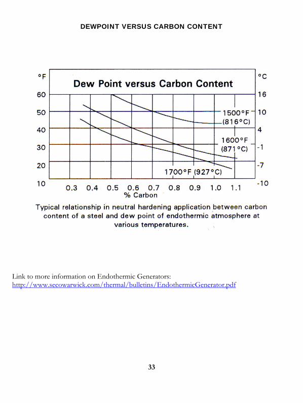
DEWPOINT VERSUS CARBON CONTENT
Link to more information on Endothermic Generators: http://www.secowarwick.com/thermal/bulletins/EndothermicGenerator.pdf
33
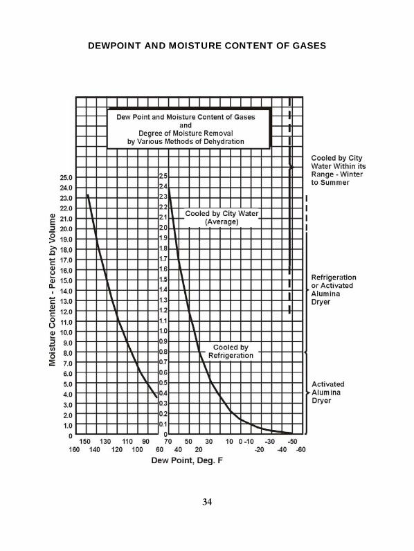
DEWPOINT AND MOISTURE CONTENT OF GASES
34
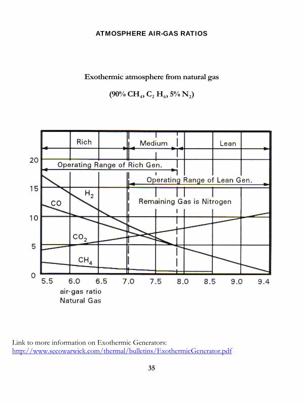
ATMOSPHERE AIR-GAS RATIOS
Exothermic atmosphere from natural gas
(90% CH , C H , 5% N ) 4 2 6 2
Link to more information on Exothermic Generators: http://www.secowarwick.com/thermal/bulletins/ExothermicGenerator.pdf
35
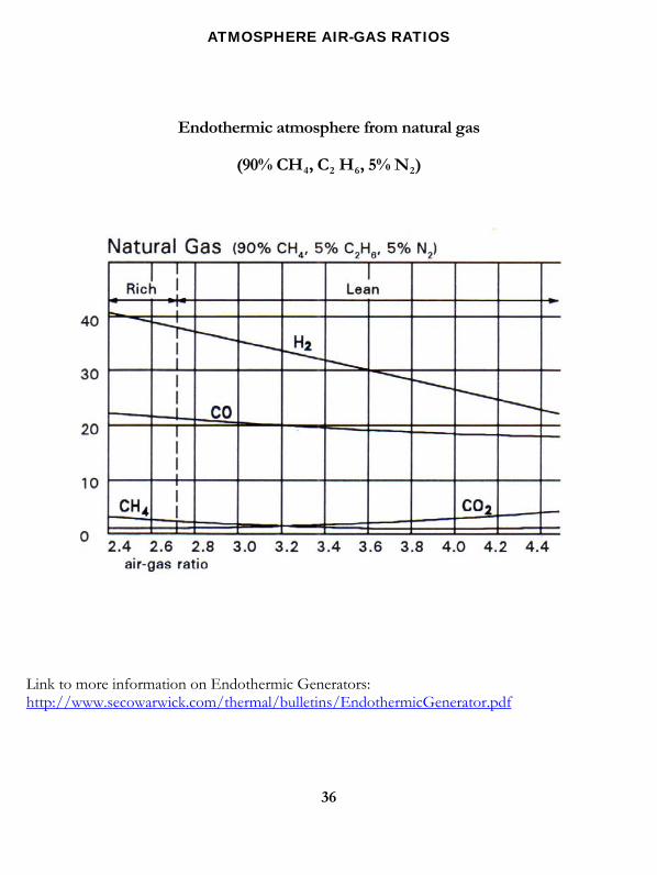
ATMOSPHERE AIR-GAS RATIOS
Endothermic atmosphere from natural gas
(90% CH , C H , 5% N ) 4 2 6 2
Link to more information on Endothermic Generators: http://www.secowarwick.com/thermal/bulletins/EndothermicGenerator.pdf
36
37
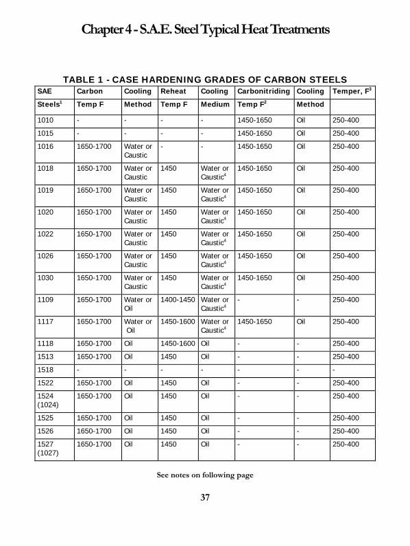
Chapter 4 - S.A.E. Steel Typical Heat Treatments
TABLE 1 - CASE HARDENING GRADES OF CARBON STEELS
SAE Carbon Cooling Reheat Cooling Carbonitriding Cooling Temper, F3
Steels1 Temp F Method Temp F Medium Temp F2 Method
1010 - - - - 1450-1650 Oil 250-400
1015 - - - - 1450-1650 Oil 250-400
1016 1650-1700 Water or Caustic
- - 1450-1650 Oil 250-400
1018 1650-1700 Water or Caustic
1450 Water or Caustic4
1450-1650 Oil 250-400
1019 1650-1700 Water or Caustic
1450 Water or Caustic4
1450-1650 Oil 250-400
1020 1650-1700 Water or Caustic
1450 Water or Caustic4
1450-1650 Oil 250-400
1022 1650-1700 Water or Caustic
1450 Water or Caustic4
1450-1650 Oil 250-400
1026 1650-1700 Water or Caustic
1450 Water or Caustic4
1450-1650 Oil 250-400
1030 1650-1700 Water or Caustic
1450 Water or Caustic4
1450-1650 Oil 250-400
1109 1650-1700 Water orOil
1400-1450 Water or Caustic4
- - 250-400
1117 1650-1700 Water or Oil
1450-1600 Water or Caustic4
1450-1650 Oil 250-400
1118 1650-1700 Oil 1450-1600 Oil - - 250-400
1513 1650-1700 Oil 1450 Oil - - 250-400
1518 - - - - - - -
1522 1650-1700 Oil 1450 Oil - - 250-400
1524 (1024)
1650-1700 Oil 1450 Oil - - 250-400
1525 1650-1700 Oil 1450 Oil - - 250-400
1526 1650-1700 Oil 1450 Oil - - 250-400
1527 (1027)
1650-1700 Oil 1450 Oil - - 250-400
See notes on following page

38
(1) Generally, it is not necessary to normalize the carbon grades for fulfilling either dimensional or machinability requirements of parts made from the steel grades listed in the table, although where dimension is of vital importance normalizing temperatures of at least 50ºF above the carburizing temperatures are sometimes required. (2) The higher manganese steels such as 1118 and the 1500 series are not usually carbonitrided. If carbonitriding is performed, care must be taken to limit the nitrogen content because high nitrogen will increase their tendency to retain austenite. (3) Even where recommended draw temperatures are shown, the draw is not mandatory on many applications. Tempering is generally employed for a partial stress relief and improves resistance to cracking from grinding operations. Higher temperatures than those shown may be employed where the hardness specification on the finished parts permits. (4) 3% sodium hydroxide. Link to S. A. E. International: http://www.sae.org/
39
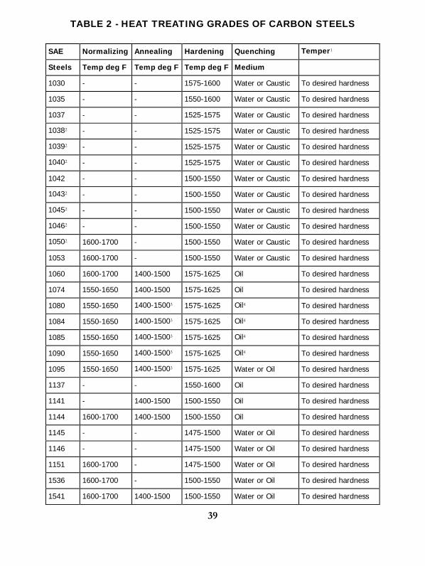
TABLE 2 - HEAT TREATING GRADES OF CARBON STEELS
SAE Normalizing Annealing Hardening Quenching Temper1
Steels Temp deg F Temp deg F Temp deg F Medium
1030 - - 1575-1600 Water or Caustic To desired hardness
1035 - - 1550-1600 Water or Caustic To desired hardness
1037 - - 1525-1575 Water or Caustic To desired hardness
10382 - - 1525-1575 Water or Caustic To desired hardness
10392 - - 1525-1575 Water or Caustic To desired hardness
10402 - - 1525-1575 Water or Caustic To desired hardness
1042 - - 1500-1550 Water or Caustic To desired hardness
10432 - - 1500-1550 Water or Caustic To desired hardness
10452 - - 1500-1550 Water or Caustic To desired hardness
10462 - - 1500-1550 Water or Caustic To desired hardness
10502 1600-1700 - 1500-1550 Water or Caustic To desired hardness
1053 1600-1700 - 1500-1550 Water or Caustic To desired hardness
1060 1600-1700 1400-1500 1575-1625 Oil To desired hardness
1074 1550-1650 1400-1500 1575-1625 Oil To desired hardness
1080 1550-1650 1400-15003 1575-1625 Oil4 To desired hardness
1084 1550-1650 1400-15003 1575-1625 Oil4 To desired hardness
1085 1550-1650 1400-15003 1575-1625 Oil4 To desired hardness
1090 1550-1650 1400-15003 1575-1625 Oil4 To desired hardness
1095 1550-1650 1400-15003 1575-1625 Water or Oil To desired hardness
1137 - - 1550-1600 Oil To desired hardness
1141 - 1400-1500 1500-1550 Oil To desired hardness
1144 1600-1700 1400-1500 1500-1550 Oil To desired hardness
1145 - - 1475-1500 Water or Oil To desired hardness
1146 - - 1475-1500 Water or Oil To desired hardness
1151 1600-1700 - 1475-1500 Water or Oil To desired hardness
1536 1600-1700 - 1500-1550 Water or Oil To desired hardness
1541 1600-1700 1400-1500 1500-1550 Water or Oil To desired hardness
40
(1041)
1548 (1048)
1600-1700 - 1500-1550 Oil To desired hardness
1552 (1052)
1600-1700 - 1500-1550 Oil To desired hardness
1566 (1066)
1600-1700 - 1575-1625 Oil To desired hardness
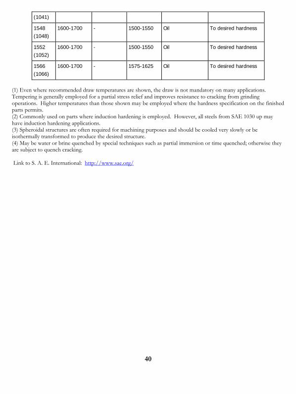
(1) Even where recommended draw temperatures are shown, the draw is not mandatory on many applications. Tempering is generally employed for a partial stress relief and improves resistance to cracking from grinding operations. Higher temperatures than those shown may be employed where the hardness specification on the finished parts permits. (2) Commonly used on parts where induction hardening is employed. However, all steels from SAE 1030 up may have induction hardening applications. (3) Spheroidal structures are often required for machining purposes and should be cooled very slowly or be isothermally transformed to produce the desired structure. (4) May be water or brine quenched by special techniques such as partial immersion or time quenched; otherwise they are subject to quench cracking. Link to S. A. E. International: http://www.sae.org/
42
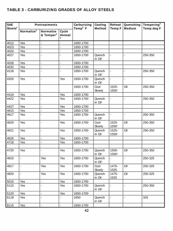
TABLE 3 - CARBURIZING GRADES OF ALLOY STEELS
Pretreatments SAE Steels1
Normalize2 Normalize & Temper3
Cycle Anneal4
Carburizing Temp5 F
Cooling Method
ReheatTemp F
QuenchingMedium
Tempering4 Temp deg F
4012 Yes - - 1650-1700 4023 Yes - - 1650-1700 4024 Yes - - 1650-1700 4027 Yes - - 1650-1700 Quench
in Oil7 - - 250-350
4028 Yes - - 1650-1700 4032 Yes - - 1650-1700 4118 Yes - - 1650-1700 Quench
in Oil7 - - 250-350
4320 Yes - Yes 1650-1700 Quench in Oil7
- -
1650-1700 Cool Slowly
1525-15509
Oil 250-350
4419 Yes - Yes 1650-1700 4422 Yes - Yes 1650-1700 Quench
in Oil7 - - 250-350
4427 Yes - Yes 1650-1700 4615 Yes - Yes 1650-1700 4617 Yes - Yes 1650-1700 Quench
in Oil7 - - 250-350
4620 Yes - Yes 1650-1700 Cool Slowly
1525-15509
Oil 250-350
4621 Yes - Yes 1650-1700 Quench in Oil
1525-15508
Oil 250-350
4626 Yes - Yes 1650-1700 4718 Yes - Yes 1650-1700 4720 Yes - Yes 1650-1700 Quench
in Oil 1500-15508
Oil 250-350
4815 - Yes Yes 1650-1700 Quench in Oil7
- - 250-325
4817 - Yes Yes 1650-1700 Cool Slowly
1475-1525
Oil 250-325
4820 - Yes Yes 1650-1700 Quench in Oil
1475-1525
Oil 250-325
5015 Yes - Yes 1650-1700 5115 Yes - Yes 1650-1700 Quench
in Oil7 - - 250-350
5120 Yes - Yes 1650-1700 6118 Yes - - 1650 Quench
in Oil7 - - 325
8115 Yes - - 1650-1700
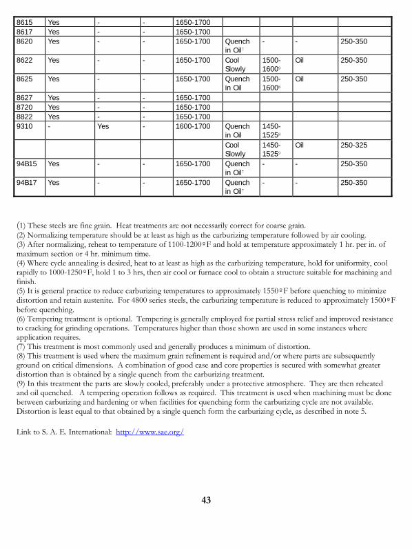
43
8615 Yes - - 1650-1700 8617 Yes - - 1650-1700 8620 Yes - - 1650-1700 Quench
in Oil7 - - 250-350
8622 Yes - - 1650-1700 Cool Slowly
1500-16009
Oil 250-350
8625 Yes - - 1650-1700 Quench in Oil
1500-16008
Oil 250-350
8627 Yes - - 1650-1700 8720 Yes - - 1650-1700 8822 Yes - - 1650-1700 9310 - Yes - 1600-1700 Quench
in Oil 1450-15258
Cool Slowly
1450-15259
Oil 250-325
94B15 Yes - - 1650-1700 Quench in Oil7
- - 250-350
94B17 Yes - - 1650-1700 Quench in Oil7
- - 250-350
(1) These steels are fine grain. Heat treatments are not necessarily correct for coarse grain. (2) Normalizing temperature should be at least as high as the carburizing temperature followed by air cooling. (3) After normalizing, reheat to temperature of 1100-1200ºF and hold at temperature approximately 1 hr. per in. of maximum section or 4 hr. minimum time. (4) Where cycle annealing is desired, heat to at least as high as the carburizing temperature, hold for uniformity, cool rapidly to 1000-1250ºF, hold 1 to 3 hrs, then air cool or furnace cool to obtain a structure suitable for machining and finish. (5) It is general practice to reduce carburizing temperatures to approximately 1550ºF before quenching to minimize distortion and retain austenite. For 4800 series steels, the carburizing temperature is reduced to approximately 1500ºF before quenching. (6) Tempering treatment is optional. Tempering is generally employed for partial stress relief and improved resistance to cracking for grinding operations. Temperatures higher than those shown are used in some instances where application requires. (7) This treatment is most commonly used and generally produces a minimum of distortion. (8) This treatment is used where the maximum grain refinement is required and/or where parts are subsequently ground on critical dimensions. A combination of good case and core properties is secured with somewhat greater distortion than is obtained by a single quench from the carburizing treatment. (9) In this treatment the parts are slowly cooled, preferably under a protective atmosphere. They are then reheated and oil quenched. A tempering operation follows as required. This treatment is used when machining must be done between carburizing and hardening or when facilities for quenching form the carburizing cycle are not available. Distortion is least equal to that obtained by a single quench form the carburizing cycle, as described in note 5. Link to S. A. E. International: http://www.sae.org/
44
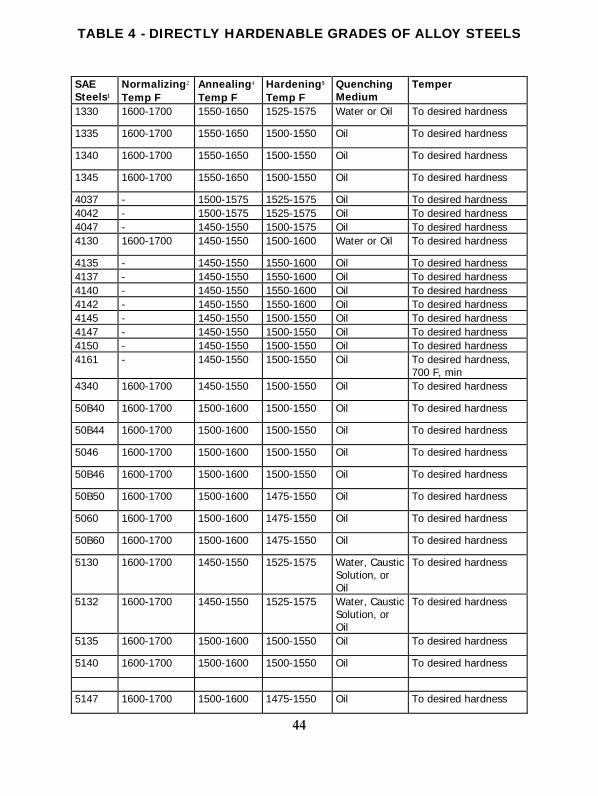
TABLE 4 - DIRECTLY HARDENABLE GRADES OF ALLOY STEELS
SAE Steels1
Normalizing2
Temp F Annealing4 Temp F
Hardening5
Temp F Quenching Medium
Temper
1330 1600-1700 1550-1650 1525-1575 Water or Oil To desired hardness
1335 1600-1700 1550-1650 1500-1550 Oil To desired hardness
1340 1600-1700 1550-1650 1500-1550 Oil To desired hardness
1345 1600-1700 1550-1650 1500-1550 Oil To desired hardness
4037 - 1500-1575 1525-1575 Oil To desired hardness 4042 - 1500-1575 1525-1575 Oil To desired hardness 4047 - 1450-1550 1500-1575 Oil To desired hardness 4130 1600-1700 1450-1550 1500-1600 Water or Oil To desired hardness
4135 - 1450-1550 1550-1600 Oil To desired hardness 4137 - 1450-1550 1550-1600 Oil To desired hardness 4140 - 1450-1550 1550-1600 Oil To desired hardness 4142 - 1450-1550 1550-1600 Oil To desired hardness 4145 - 1450-1550 1500-1550 Oil To desired hardness 4147 - 1450-1550 1500-1550 Oil To desired hardness 4150 - 1450-1550 1500-1550 Oil To desired hardness 4161 - 1450-1550 1500-1550 Oil To desired hardness,
700 F, min 4340 1600-1700 1450-1550 1500-1550 Oil To desired hardness
50B40 1600-1700 1500-1600 1500-1550 Oil To desired hardness
50B44 1600-1700 1500-1600 1500-1550 Oil To desired hardness
5046 1600-1700 1500-1600 1500-1550 Oil To desired hardness
50B46 1600-1700 1500-1600 1500-1550 Oil To desired hardness
50B50 1600-1700 1500-1600 1475-1550 Oil To desired hardness
5060 1600-1700 1500-1600 1475-1550 Oil To desired hardness
50B60 1600-1700 1500-1600 1475-1550 Oil To desired hardness
5130 1600-1700 1450-1550 1525-1575 Water, Caustic Solution, or Oil
To desired hardness
5132 1600-1700 1450-1550 1525-1575 Water, Caustic Solution, or Oil
To desired hardness
5135 1600-1700 1500-1600 1500-1550 Oil To desired hardness
5140 1600-1700 1500-1600 1500-1550 Oil To desired hardness
5147 1600-1700 1500-1600 1475-1550 Oil To desired hardness

45
5150 1600-1700 1500-1600 1475-1550 Oil To desired hardness
5155 1600-1700 1500-1600 1475-1550 Oil To desired hardness
5160 1600-1700 1500-1600 1475-1550 Oil To desired hardness
51B60 1600-1700 1500-1600 1475-1550 Oil To desired hardness
50100 - 1350-1450 1425-1475 Water To desired hardness 51100 - 1350-1450 1500-1600 Oil To desired hardness 52100 - 1350-1450 To desired hardness 6150 - 1550-1650 1550-1625 Oil To desired hardness 61B45 1600-1700 1550-1650 1500-1575 Oil To desired hardness
8630 1600-1700 1450-1550 1525-1600 Water or Oil To desired hardness 8637 - 1500-1600 1525-1575 Oil To desired hardness 8640 - 1500-1600 1525-1575 Oil To desired hardness 8642 - 1500-1600 1500-1575 Oil To desired hardness 8645 - 1500-1600 1500-1575 Oil To desired hardness 86B45 - 1500-1600 1500-1575 Oil To desired hardness 8650 - 1500-1600 1500-1575 Oil To desired hardness 8655 - 1500-1600 1475-1550 Oil To desired hardness 8660 - 1500-1600 1475-1550 Oil To desired hardness 8740 - 1500-1600 1525-1575 Oil To desired hardness 9254 - - 1500-1650 Oil To desired hardness 9260 - - 1500-1650 Oil To desired hardness 94B30 1600-1700 1450-1550 1550-1625 Oil To desired hardness
(1) These steels are fine grain unless otherwise specified. (2) These steels should be either normalized or annealed for optimum machinability. (3) Temper at 110-1225. (4) The specific annealing cycle is dependent upon the alloy content of the steel, the type of subsequent machining operations and desired surface finish. (5) Frequently, these steels, with the exception of 4340, 50100, 51100, and 52100, are hardened and tempered to a final machinable hardness without preliminary heat treatment. Link to S. A. E. International: http://www.sae.org/
46
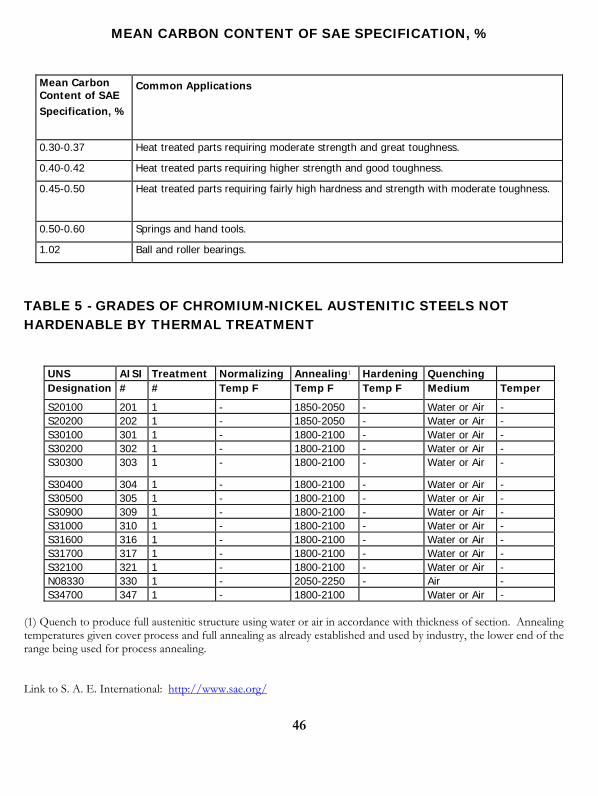
MEAN CARBON CONTENT OF SAE SPECIFICATION, %
Mean Carbon Content of SAE Specification, %
Common Applications
0.30-0.37 Heat treated parts requiring moderate strength and great toughness.
0.40-0.42 Heat treated parts requiring higher strength and good toughness.
0.45-0.50 Heat treated parts requiring fairly high hardness and strength with moderate toughness.
0.50-0.60 Springs and hand tools.
1.02 Ball and roller bearings.
TABLE 5 - GRADES OF CHROMIUM-NICKEL AUSTENITIC STEELS NOT HARDENABLE BY THERMAL TREATMENT
UNS AISI Treatment Normalizing Annealing1 Hardening Quenching Designation # # Temp F Temp F Temp F Medium Temper
S20100 201 1 - 1850-2050 - Water or Air - S20200 202 1 - 1850-2050 - Water or Air - S30100 301 1 - 1800-2100 - Water or Air - S30200 302 1 - 1800-2100 - Water or Air - S30300 303 1 - 1800-2100 - Water or Air -
S30400 304 1 - 1800-2100 - Water or Air - S30500 305 1 - 1800-2100 - Water or Air - S30900 309 1 - 1800-2100 - Water or Air - S31000 310 1 - 1800-2100 - Water or Air - S31600 316 1 - 1800-2100 - Water or Air - S31700 317 1 - 1800-2100 - Water or Air - S32100 321 1 - 1800-2100 - Water or Air - N08330 330 1 - 2050-2250 - Air - S34700 347 1 - 1800-2100 Water or Air -
(1) Quench to produce full austenitic structure using water or air in accordance with thickness of section. Annealing temperatures given cover process and full annealing as already established and used by industry, the lower end of the range being used for process annealing. Link to S. A. E. International: http://www.sae.org/

47
TABLE 6 - STAINLESS CHROMIUM STEELS
AISI Treatment Normal-izing
Subcritical Annealing
Full Annealing1
Hardening Quenching SAE Steels
# # Temp F Temp F Temp F Temp F Medium Temper
S40900 409 1 - - 1550-1650 - Air - S41000 410 1 - 1300-13502 1550-1650 - Oil or Air To desired
hardness 2 - - - 1750-1850 S41400 414 1 - 1200-12502 - - Oil or Air To desired
hardness 2 - - - 1750-1850 S41600 416 1 - 1300-13502 1550-1650 - Oil or Air To desired
hardness 2 - - - 1750-1850 S42000 420 1 - 1350-14502 1550-1650 - Oil or Air To desired
hardness 2 - - - 1800-1850 S42020 420F 1 - 1350-14502 1550-1650 - Oil or Air To desired
hardness 2 - - - 1800-1850 S43000 430 1 - 1400-15004 - - - -
S43020 430F 1 - 1250-15004 - - - -
S43100 431 1 - 1150-12252 - 1800-1900 Oil or Air To desired hardness
S43400 434 S43600 436 1 - 1400-15004 - - - -
S44002 440A
S44003 440B
S44004 440C3 - 1350-14402 1550-1650 1850-1950 Oil or Air To desired hardness
S44200 442 1 - 1440-15004 - - - -
S44600 446 1 - 1500-16502 - - - -
51501 501 - 1325-13754 1525-1600 1600-1700 Oil or Air To desired hardness
(1) Cool slowly in furnace. (2) Usually air-cooled but may be furnace cooled. (3) Suffixes A, B, and C denote three types of steel differing only in carbon content. Suffix F denotes a free machining steel (4) Cool rapidly in air. Link to S. A. E. International: http://www.sae.org/
48
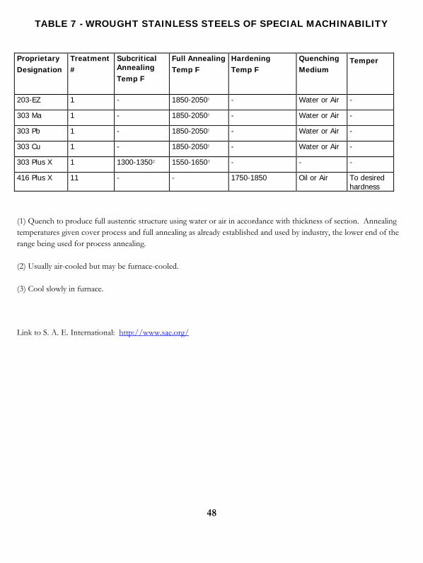
TABLE 7 - WROUGHT STAINLESS STEELS OF SPECIAL MACHINABILITY
Proprietary Designation
Treatment #
Subcritical Annealing Temp F
Full Annealing Temp F
Hardening Temp F
Quenching Medium
Temper
203-EZ 1 - 1850-20501 - Water or Air -
303 Ma 1 - 1850-20501 - Water or Air -
303 Pb 1 - 1850-20501 - Water or Air -
303 Cu 1 - 1850-20501 - Water or Air -
303 Plus X 1 1300-13502 1550-16503 - - -
416 Plus X 11 - - 1750-1850 Oil or Air To desired hardness
(1) Quench to produce full austentic structure using water or air in accordance with thickness of section. Annealing temperatures given cover process and full annealing as already established and used by industry, the lower end of the range being used for process annealing.
(2) Usually air-cooled but may be furnace-cooled.
(3) Cool slowly in furnace.
Link to S. A. E. International: http://www.sae.org/
49
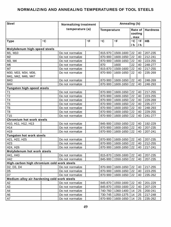
NORMALIZING AND ANNEALING TEMPERATURES OF TOOL STEELS
Annealing (b) Steel Normalizing treatment temperature (a) Temperature Rate of
cooling, max
Hardness
Type °C °F °C °F °C/h
°F/h
HB
Molybdenum high-speed steels M1, M10 Do not normalize 815-970 1500-1600 22 40 207-235 M2 Do not normalize 870-900 1600-1650 22 40 212-241 M3, M4 Do not normalize 870-900 1600-1650 22 40 223-255 M6 Do not normalize 870 1600 22 40 248-277 M7 Do not normalize 815-870 1500-1600 22 40 217-255 M30, M33, M34, M36, M41, M42, M46, M47
Do not normalize 870-900 1600-1650 22 40 235-269
M43 Do not normalize 870-900 1600-1650 22 40 248-269 M44 Do not normalize 870-900 1600-1650 22 40 248-293 Tungsten high-speed steels T1 Do not normalize 870-900 1600-1650 22 40 217-255 T2 Do not normalize 870-900 1600-1650 22 40 223-255 T4 Do not normalize 870-900 1600-1650 22 40 229-269 T5 Do not normalize 870-900 1600-1650 22 40 235-277 T6 Do not normalize 870-900 1600-1650 22 40 248-293 T8 Do not normalize 870-900 1600-1650 22 40 229-255 T15 Do not normalize 870-900 1600-1650 22 40 241-277 Chromium hot work steels H10, H11, H12, H13 Do not normalize 845-900 1550-1650 22 40 192-229 H14 Do not normalize 870-900 1600-1650 22 40 207-235 H19 Do not normalize 870-900 1600-1650 22 40 207-241 Tungsten hot work steels H21, H22, H25 Do not normalize 870-900 1600-1650 22 40 207-235 H23 Do not normalize 870-900 1600-1650 22 40 212-255 H24, H26 Do not normalize 870-900 1600-1650 22 40 217-241 Molybdenum hot work steels H41, H43 Do not normalize 815-870 1500-1600 22 40 207-235 H42 Do not normalize 845-900 1550-1650 22 40 207-235 High-carbon high chromium cold work steels D2, D3, D4 Do not normalize 870-900 1600-1650 22 40 217-255 D5 Do not normalize 870-900 1600-1650 22 40 223-255 D7 Do not normalize 870-900 1600-1650 22 40 235-262 Medium-alloy air-hardening cold work steels A2 Do not normalize 845-870 1550-1600 22 40 201-229 A3 Do not normalize 845-870 1550-1600 22 40 207-229 A4 Do not normalize 740-760 1360-1400 14 25 200-241 A6 Do not normalize 730-745 1350-1375 14 25 217-248 A7 Do not normalize 870-900 1600-1650 14 25 235-262

50
A8 Do not normalize 845-870 1550-1600 22 40 192-223 A9 Do not normalize 845-870 1550-1600 14 25 212-248 A10 790 1450 765-795 1410-1460 8 15 235-269 Oil-hardening cold work steels O1 870 1600 760-790 1400-1450 22 40 183-212 O2 845 1550 745-775 1375-1425 22 40 183-212 O6 870 1600 765-790 1410-1450 11 20 183-217 O7 900 1650 790-815 1450-1500 22 40 192-217 Shock-resisting steels S1 Do not normalize 790-815 1450-1500 22 40 183-229(c) S2 Do not normalize 760-790 1400-1450 22 40 192-217 S5 Do not normalize 775-800 1425-1475 14 25 192-229 S7 Do not normalize 815-845 1500-1550 14 25 187-223 Mold steels P2 Not required 730 1350-1500 22 40 103-123 P3 Not required 815 1350-1500 22 40 109-137 P4 Do not normalize 870-900 1600-1650 14 25 116-128 P5 Not required 845-870 1550-1600 22 40 105-116 P6 Not required 845 1550 8 15 183-217 P20 900 1650 760-790 1400-1450 22 40 149-179 P21 900 1650 Do not anneal
Low-alloy special-purpose steels L2 870-900 1600-
1650 760-790 1400-1450 22 40 163-197
L3 900 1650 790-815 1450-1500 22 40 174-201 L6 870 1600 760-790 1400-1450 22 40 183-212 Carbon-tungsten special-purpose steels F1 900 1650 760-800 1400-1475 22 40 183-207 F2 900 1650 790-815 1450-1500 22 40 207-235 Water-hardening steels W1, W2 790-
925(d) 1450-
1700(d) 740-790(e)
1360-1450(e)
22 40 156-201
W5 870-925 1600-1700
760-790 1400-1450 22 40 163-201
(a) Time held at temperature varies from 15 min for small sections to 1 h for large sizes. Cooling is done in still air. Normalizing should not be confused with low-temperature annealing. (b) The upper limit of ranges should be used for large sections and the lower limit for smaller sections. Time held at temperature varies from 1 h for light sections to 4 h for heavy sections and large furnace charges of high alloy steel. (c) For 0.25 Si type 183 to 207 HB; for 1.00 Si type, 207 to 229 HB. (d) Temperature varies with carbon content: 0.60 to 0.75ºC, 815ºC (1500°F); 0.75 to 0.90 ºC, 790ºC (1450ºF); 0.90 to 1.10ºC, 870ºC (1600ºF); 1.10 to 1.40 ºC, 870 to 925ºF (1600 to 1700ºF). (e) Temperature varies with carbon content: 0.60 to 0.90 ºC, 740 to 790ºC (1360 to 1450ºF); 0.90 to 1.40 ºC, 760 to 790ºC (1400 to 1450ºF). Source: ASM Handbook Vol. 4, page 715, table 2. http://products.asminternational.org/hbk/index.jsp
51
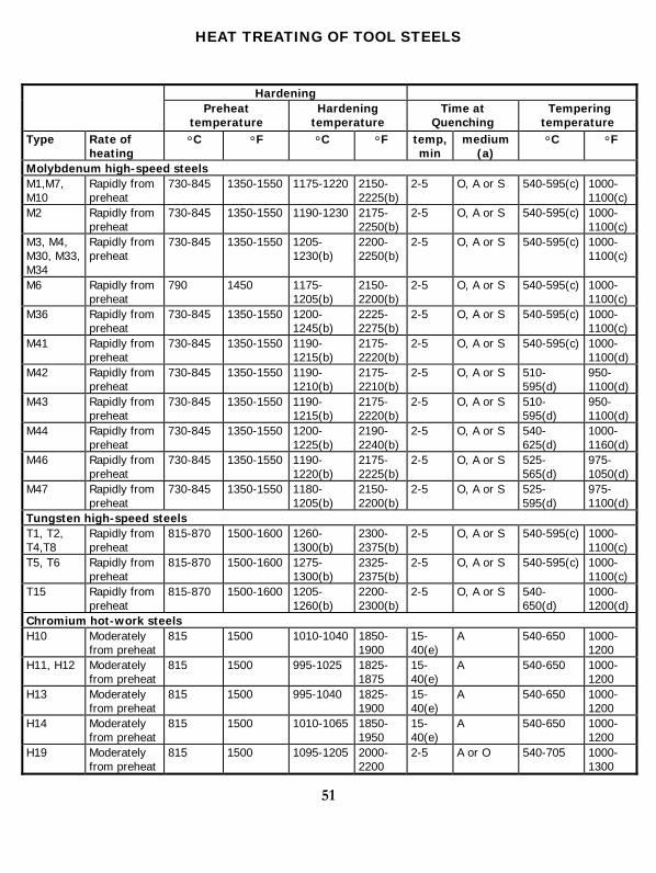
HEAT TREATING OF TOOL STEELS
Hardening Preheat
temperature Hardening
temperature Time at
Quenching Tempering
temperature Type Rate of
heating °C °F °C °F temp,
min medium
(a) °C °F
Molybdenum high-speed steels M1,M7, M10
Rapidly from preheat
730-845 1350-1550 1175-1220 2150-2225(b)
2-5 O, A or S 540-595(c) 1000-1100(c)
M2 Rapidly from preheat
730-845 1350-1550 1190-1230 2175-2250(b)
2-5 O, A or S 540-595(c) 1000-1100(c)
M3, M4, M30, M33, M34
Rapidly from preheat
730-845 1350-1550 1205-1230(b)
2200-2250(b)
2-5 O, A or S 540-595(c) 1000-1100(c)
M6 Rapidly from preheat
790 1450 1175-1205(b)
2150-2200(b)
2-5 O, A or S 540-595(c) 1000-1100(c)
M36 Rapidly from preheat
730-845 1350-1550 1200-1245(b)
2225-2275(b)
2-5 O, A or S 540-595(c) 1000-1100(c)
M41 Rapidly from preheat
730-845 1350-1550 1190-1215(b)
2175-2220(b)
2-5 O, A or S 540-595(c) 1000-1100(d)
M42 Rapidly from preheat
730-845 1350-1550 1190-1210(b)
2175-2210(b)
2-5 O, A or S 510-595(d)
950-1100(d)
M43 Rapidly from preheat
730-845 1350-1550 1190-1215(b)
2175-2220(b)
2-5 O, A or S 510-595(d)
950-1100(d)
M44 Rapidly from preheat
730-845 1350-1550 1200-1225(b)
2190-2240(b)
2-5 O, A or S 540-625(d)
1000-1160(d)
M46 Rapidly from preheat
730-845 1350-1550 1190-1220(b)
2175-2225(b)
2-5 O, A or S 525-565(d)
975-1050(d)
M47 Rapidly from preheat
730-845 1350-1550 1180-1205(b)
2150-2200(b)
2-5 O, A or S 525-595(d)
975-1100(d)
Tungsten high-speed steels T1, T2, T4,T8
Rapidly from preheat
815-870 1500-1600 1260-1300(b)
2300-2375(b)
2-5 O, A or S 540-595(c) 1000-1100(c)
T5, T6 Rapidly from preheat
815-870 1500-1600 1275-1300(b)
2325-2375(b)
2-5 O, A or S 540-595(c) 1000-1100(c)
T15 Rapidly from preheat
815-870 1500-1600 1205-1260(b)
2200-2300(b)
2-5 O, A or S 540-650(d)
1000-1200(d)
Chromium hot-work steels H10 Moderately
from preheat 815 1500 1010-1040 1850-
1900 15-40(e)
A 540-650 1000-1200
H11, H12 Moderately from preheat
815 1500 995-1025 1825-1875
15-40(e)
A 540-650 1000-1200
H13 Moderately from preheat
815 1500 995-1040 1825-1900
15-40(e)
A 540-650 1000-1200
H14 Moderately from preheat
815 1500 1010-1065 1850-1950
15-40(e)
A 540-650 1000-1200
H19 Moderately from preheat
815 1500 1095-1205 2000-2200
2-5 A or O 540-705 1000-1300
52
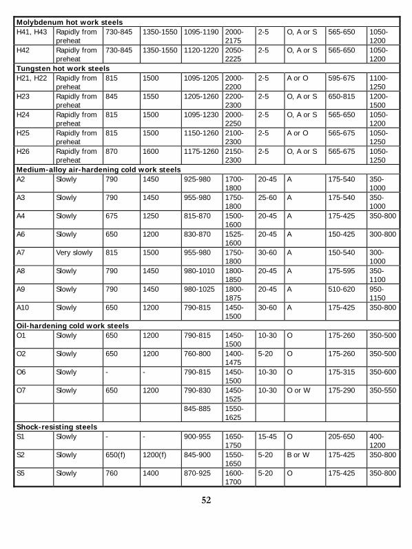
Molybdenum hot work steels H41, H43 Rapidly from
preheat 730-845 1350-1550 1095-1190 2000-
2175 2-5 O, A or S 565-650 1050-
1200 H42 Rapidly from
preheat 730-845 1350-1550 1120-1220 2050-
2225 2-5 O, A or S 565-650 1050-
1200 Tungsten hot work steels H21, H22 Rapidly from
preheat 815 1500 1095-1205 2000-
2200 2-5 A or O 595-675 1100-
1250 H23 Rapidly from
preheat 845 1550 1205-1260 2200-
2300 2-5 O, A or S 650-815 1200-
1500 H24 Rapidly from
preheat 815 1500 1095-1230 2000-
2250 2-5 O, A or S 565-650 1050-
1200 H25 Rapidly from
preheat 815 1500 1150-1260 2100-
2300 2-5 A or O 565-675 1050-
1250 H26 Rapidly from
preheat 870 1600 1175-1260 2150-
2300 2-5 O, A or S 565-675 1050-
1250 Medium-alloy air-hardening cold work steels A2 Slowly 790 1450 925-980 1700-
1800 20-45 A 175-540 350-
1000 A3 Slowly 790 1450 955-980 1750-
1800 25-60 A 175-540 350-
1000 A4 Slowly 675 1250 815-870 1500-
1600 20-45 A 175-425 350-800
A6 Slowly 650 1200 830-870 1525-1600
20-45 A 150-425 300-800
A7 Very slowly 815 1500 955-980 1750-1800
30-60 A 150-540 300-1000
A8 Slowly 790 1450 980-1010 1800-1850
20-45 A 175-595 350-1100
A9 Slowly 790 1450 980-1025 1800-1875
20-45 A 510-620 950-1150
A10 Slowly 650 1200 790-815 1450-1500
30-60 A 175-425 350-800
Oil-hardening cold work steels O1 Slowly 650 1200 790-815 1450-
1500 10-30 O 175-260 350-500
O2 Slowly 650 1200 760-800 1400-1475
5-20 O 175-260 350-500
O6 Slowly - - 790-815 1450-1500
10-30 O 175-315 350-600
O7 Slowly 650 1200 790-830 1450-1525
10-30 O or W 175-290 350-550
845-885 1550-1625
Shock-resisting steels S1 Slowly - - 900-955 1650-
1750 15-45 O 205-650 400-
1200 S2 Slowly 650(f) 1200(f) 845-900 1550-
1650 5-20 B or W 175-425 350-800
S5 Slowly 760 1400 870-925 1600-1700
5-20 O 175-425 350-800
53
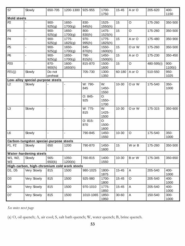
S7 Slowly 650-705 1200-1300 925-955 1700-1750
15-45 A or O 205-620 400-1150
Mold steels P2 - 900-
925(g) 1650-1700(g)
830-845(h)
1525-1550(h)
15 O 175-260 350-500
P3 - 900-925(g)
1650-1700(g)
800-830(h)
1475-1525(h)
15 O 175-260 350-500
P4 - 900-925(g)
1775-1825(g)
970-995(h)
1775-1825(h)
15 A or O 175-480 350-900
P5 - 900-925(g)
1650-1700(g)
845-870(h)
1550-1600(h)
15 O or W 175-260 350-500
P6 - 900-925(g)
1650-1700(g)
790-815(h)
1450-1500(h)
15 A or O 175-230 350-450
P20 - 870-900(h)
1600-1650(h)
815-870 1500-1600
15 O 480-595(i) 900-1100(i)
P21(j) Slowly Do not preheat
705-730 1300-1350
60-180 A or O 510-550 950-1025
Low-alloy special-purpose steels L2 Slowly - - W: 790-
845 W: 1450-1550
10-30 O or W 175-540 350-1000
O: 845-925
O: 1550-1700
L3 Slowly - - W: 775-815
W: 1425-1500
10-30 O or W 175-315 350-600
O: 815-870
O: 1500-1600
L6 Slowly - - 790-845 1450-1550
10-30 O 175-540 350-1000
Carbon-tungsten special-purpose steels F1, F2 Slowly 650 1200 790-870 1450-
1600 15 W or B 175-260 350-500
Water-hardening steels W1, W2, W3
Slowly 565-650(k)
1050-1200(k)
760-815 1400-1550
10-30 B or W 175-345 350-650
High-carbon, high-chromium cold work steels D1, D5 Very Slowly 815 1500 980-1025 1800-
1875 15-45 A 205-540 400-
1000 D3 Very Slowly 815 1500 925-980 1700-
1800 15-45 O 205-540 400-
1000 D4 Very Slowly 815 1500 970-1010 1775-
1850 15-45 A 205-540 400-
1000 D7 Very Slowly 815 1500 1010-1065 1850-
1950 30-60 A 150-540 300-
1000 See notes next page (a) O, oil quench; A, air cool; S, salt bath quench; W, water quench; B, brine quench.
54
(b) When the high-temperature heating is carried out in a salt bath, the range of temperatures should be about 15ºC (25ºF) lower than given in this line. (c) Double tempering recommended for not less than 1 h at temperature each time. (d) Triple tempering recommended for not less than 1 h at temperature each time. (e) Times apply to open-furnace heat treatment. For pack hardening, a common rule is to heat 1.2 min/mm (30 min/in.) of cross section of the pack. (f) Preferable for large tools to minimize decarburization. (g) Carburizing temperature. (h) After carburizing. (i) Carburized case hardness. (j) P21 is a precipitation-hardening steel having a thermal treatment that involves solution treating and aging rather than hardening and tempering. (k) Recommended for large tools and tools with intricate sections.
Source: ASM Handbook Vol. 4, page 716-717, table 3. http://products.asminternational.org/hbk/index.jsp
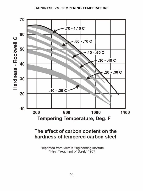
HARDNESS VS. TEMPERING TEMPERATURE
55

56
CARBURIZING TIMES AND TEMPERATURES
Temperature, ºF Time in Hours
1400 1450 1500 1550 1600 1650 1700 1750 1800 1850
1 0.008 0.010 0.012 0.015 0.018 0.021 0.025 0.029 0.034 0.040 2 0.011 0.014 0.017 0.021 0.025 0.030 0.035 0.041 0.048 0.056 3 0.014 0.017 0.021 0.025 0.031 0.037 0.043 0.051 0.059 0.069 4 0.016 0.020 0.024 0.029 0.035 0.042 0.050 0.059 0.069 0.079 5 0.018 0.022 0.027 0.033 0.040 0.047 0.056 0.066 0.077 0.089 6 0.019 0.024 0.030 0.036 0.043 0.052 0.061 0.072 0.084 0.097 7 0.021 0.026 0.032 0.039 0.047 0.056 0.066 0.078 0.091 0.105 8 0.022 0.028 0.034 0.041 0.050 0.060 0.071 0.083 0.097 0.112 9 0.024 0.029 0.036 0.044 0.053 0.063 0.075 0.088 0.103 0.119 10 0.025 0.031 0.038 0.046 0.056 0.067 0.079 0.093 0.108 0.126 11 0.026 0.033 0.040 0.048 0.059 0.070 0.083 0.097 0.113 0.132 12 0.027 0.034 0.042 0.051 0.061 0.073 0.087 0.102 0.119 0.138 13 0.028 0.035 0.043 0.053 0.064 0.076 0.090 0.106 0.123 0.143 14 0.029 0.037 0.045 0.055 0.066 0.079 0.094 0.110 0.128 0.149 15 0.031 0.039 0.047 0.057 0.068 0.082 0.097 0.114 0.133 0.154 16 0.032 0.039 0.048 0.059 0.071 0.084 0.100 0.117 0.137 0.159 17 0.033 0.040 0.050 0.060 0.073 0.087 0.103 0.121 0.141 0.164 18 0.033 0.042 0.051 0.062 0.075 0.090 0.106 0.125 0.145 0.169 19 0.034 0.043 0.053 0.064 0.077 0.092 0.109 0.128 0.149 0.173 20 0.035 0.044 0.054 0.066 0.079 0.094 0.112 0.131 0.153 0.178 21 0.036 0.045 0.055 0.067 0.081 0.097 0.114 0.134 0.157 0.182 22 0.037 0.046 0.056 0.069 0.083 0.099 0.117 0.138 0.161 0.186 23 0.038 0.047 0.058 0.070 0.085 0.101 0.120 0.141 0.164 0.190 24 0.039 0.048 0.059 0.072 0.086 0.103 0.122 0.144 0.168 0.195 25 0.039 0.049 0.060 0.073 0.088 0.106 0.125 0.147 0.171 0.199 26 0.040 0.050 0.061 0.075 0.090 0.108 0.127 0.150 0.175 0.203 27 0.041 0.051 0.063 0.076 0.092 0.110 0.130 0.153 0.178 0.206 28 0.042 0.052 0.064 0.078 0.094 0.112 0.132 0.155 0.181 0.210 29 0.042 0.053 0.065 0.079 0.095 0.114 0.134 0.158 0.185 0.214 30 0.043 0.054 0.066 0.080 0.097 0.116 0.137 0.161 0.188 0.217
For Example: 4320 carburized at 1700ºF for 11 hours at temperature would attain “case depth” of 0.083 inches. If 0.100 inches were specified it would require 16 hours. Source: Metal Progress, August 1943.

CARBONITRIDING CHART
57
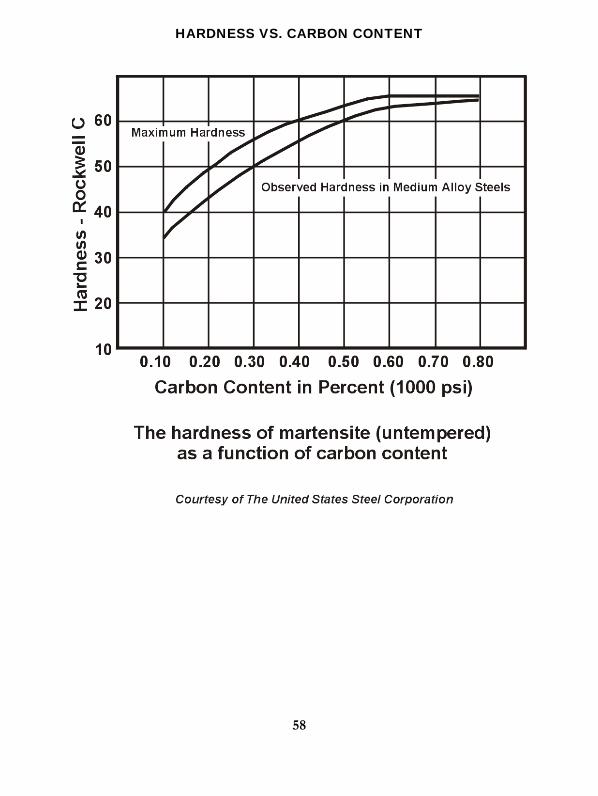
HARDNESS VS. CARBON CONTENT
58
59
Chapter 5 -Vacuum Heat Treatment
INTRODUCTION The development of commercial vacuum furnace equipment for industry began in the 1950's. Metallurgical processes such as annealing, hardening, sintering, tempering, brazing, and diffusion bonding can be carried out in vacuum. Vacuum may also be used to purge a chamber prior to introduction of a controlled atmosphere. As new applications for vacuum heat treating are discovered, the market for equipment continues to expand.
Any substance exposed to the atmosphere will adsorb and absorb molecules of air, microscopic dust, water, and chemical vapors and bacteria. Over time, this material will react chemically with the main body substance to produce oxides, nitrides, or complex organic coatings, which may be undesirable and are considered contaminants or impurities. Thermal processing in standard heat treating equipment under oxidizing or reducing atmosphere removes or changes these contaminants through chemical reaction. The reduction of oxides with hydrogen and resultant formation of water vapor is a good example.
A primary difference in this oxide reduction between vacuum heat treating and conventional heat treating (protective atmosphere) is the kind of reaction that takes place. Here, dissociation pressures of compounds govern instead of chemical reaction rates between elements and gas atmospheres. These concepts are no more difficult than the chemical reactions of prepared atmospheres, but they are perhaps a little less familiar. Many of the common oxides that are present break down spontaneously by dissociation in vacuum, at moderate temperatures without the use of a reducing agent.
This effect of vacuum processing can be compared to processing in an atmosphere furnace at a specific moisture content or dewpoint. Dewpoint versus vacuum level is not a true comparison of environment, but is useful for comparing processes, particularly those requiring dry hydrogen for bright annealing, hardening, and brazing of stainless steels. If a process requires -100°F dewpoint hydrogen, a vacuum level of 1 x 10⁻³ Torr may suffice to provide a bright surface. The cleaning ability and protection afforded by vacuum without the requirement of expensive or combustible process gases make it attractive.
Vacuum equipment is generally cool, clean, quiet, and efficient. Vacuum processing is flexible, adaptable, reliable, and economical, and environmentally friendly.
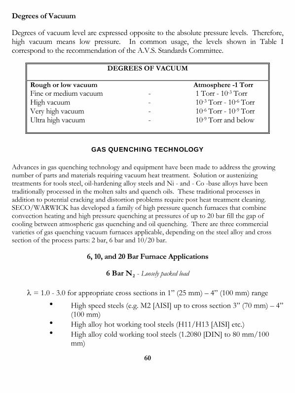
60
Degrees of Vacuum
Degrees of vacuum level are expressed opposite to the absolute pressure levels. Therefore, high vacuum means low pressure. In common usage, the levels shown in Table I correspond to the recommendation of the A.V.S. Standards Committee.
DEGREES OF VACUUM
Rough or low vacuum Atmosphere -1 Torr Fine or medium vacuum - 1 Torr - 10-3 Torr High vacuum - 10-3 Torr - 10-6 Torr Very high vacuum - 10-6 Torr - 10-9 Torr Ultra high vacuum - 10-9 Torr and below
GAS QUENCHING TECHNOLOGY Advances in gas quenching technology and equipment have been made to address the growing number of parts and materials requiring vacuum heat treatment. Solution or austenizing treatments for tools steel, oil-hardening alloy steels and Ni - and - Co -base alloys have been traditionally processed in the molten salts and quench oils. These traditional processes in addition to potential cracking and distortion problems require post heat treatment cleaning. SECO/WARWICK has developed a family of high pressure quench furnaces that combine convection heating and high pressure quenching at pressures of up to 20 bar fill the gap of cooling between atmospheric gas quenching and oil quenching. There are three commercial varieties of gas quenching vacuum furnaces applicable, depending on the steel alloy and cross section of the process parts: 2 bar, 6 bar and 10/20 bar.
6, 10, and 20 Bar Furnace Applications
6 Bar N2 - Loosely packed load
= 1.0 - 3.0 for appropriate cross sections in 1” (25 mm) – 4” (100 mm) range
High speed steels (e.g. M2 [AISI] up to cross section 3” (70 mm) – 4” (100 mm)
High alloy hot working tool steels (H11/H13 [AISI] etc.) High alloy cold working tool steels (1.2080 [DIN] to 80 mm/100
mm)
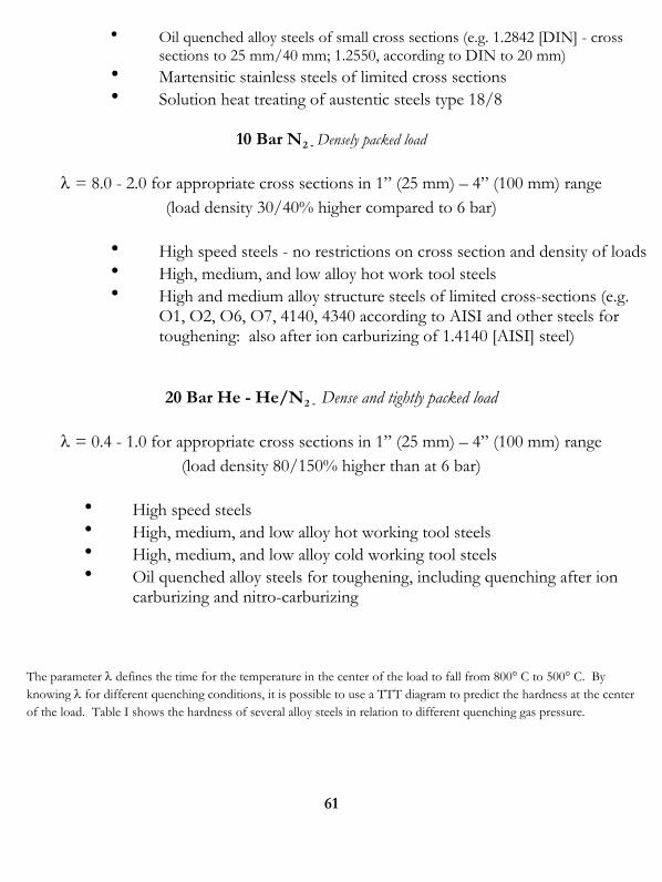
61
Oil quenched alloy steels of small cross sections (e.g. 1.2842 [DIN] - cross sections to 25 mm/40 mm; 1.2550, according to DIN to 20 mm)
Martensitic stainless steels of limited cross sections Solution heat treating of austentic steels type 18/8
10 Bar N2 - Densely packed load
= 8.0 - 2.0 for appropriate cross sections in 1” (25 mm) – 4” (100 mm) range (load density 30/40% higher compared to 6 bar)
High speed steels - no restrictions on cross section and density of loads High, medium, and low alloy hot work tool steels High and medium alloy structure steels of limited cross-sections (e.g.
O1, O2, O6, O7, 4140, 4340 according to AISI and other steels for toughening: also after ion carburizing of 1.4140 [AISI] steel)
20 Bar He - He/N2 - Dense and tightly packed load
= 0.4 - 1.0 for appropriate cross sections in 1” (25 mm) – 4” (100 mm) range (load density 80/150% higher than at 6 bar)
High speed steels High, medium, and low alloy hot working tool steels High, medium, and low alloy cold working tool steels Oil quenched alloy steels for toughening, including quenching after ion
carburizing and nitro-carburizing
The parameter defines the time for the temperature in the center of the load to fall from 800° C to 500° C. By knowing for different quenching conditions, it is possible to use a TTT diagram to predict the hardness at the center of the load. Table I shows the hardness of several alloy steels in relation to different quenching gas pressure.
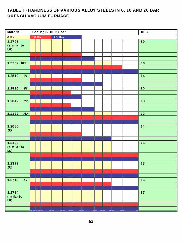
62
TABLE I - HARDNESS OF VARIOUS ALLOY STEELS IN 6, 10 AND 20 BAR QUENCH VACUUM FURNACE
Material Cooling 6/10/20 bar HRC
6 Bar 10 Bar 20 Bar 1.2721-(similar to L6)
59
1.2767- 6F7 56 1.2510 01 64 1.2550 S1 60 1.2842 02 63 1.2363 A2 63 1.2080 D3
64
1.2436 (similar to L6)
65
1.2379 D2
63
1.2713 L6 56 1.2714 (imilar to L6)
57
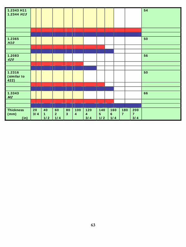
63
1.2343 H11 1.2344 H13
54
1.2365 H10
50
1.2083 420
56
1.2316 (similar to 422)
50
1.3343 M2
66
Thickness (mm) (in)
20 3/4
40 1 1/2
60 2 1/4
803
1004
120 4 3/4
140 5 1/2
160 6 1/4
1807
200 7 3/4
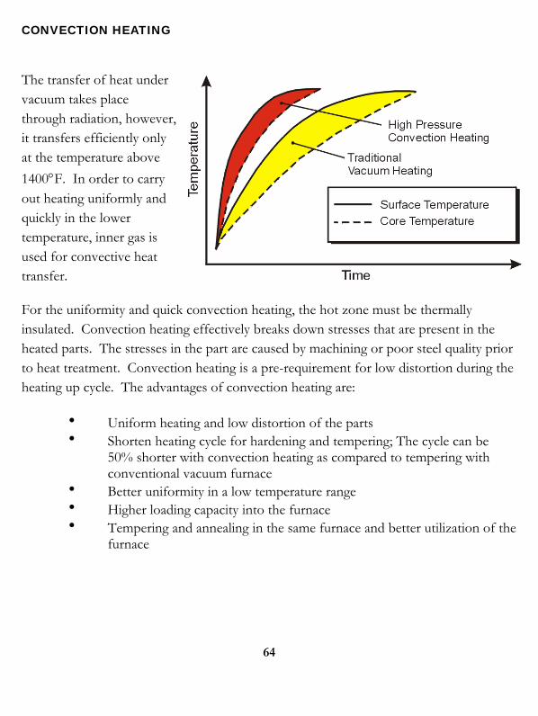
CONVECTION HEATING
The transfer of heat under vacuum takes place through radiation, however, it transfers efficiently only at the temperature above
1400F. In order to carry out heating uniformly and quickly in the lower temperature, inner gas is used for convective heat transfer.
For the uniformity and quick convection heating, the hot zone must be thermally insulated. Convection heating effectively breaks down stresses that are present in the heated parts. The stresses in the part are caused by machining or poor steel quality prior to heat treatment. Convection heating is a pre-requirement for low distortion during the heating up cycle. The advantages of convection heating are:
Uniform heating and low distortion of the parts Shorten heating cycle for hardening and tempering; The cycle can be
50% shorter with convection heating as compared to tempering with conventional vacuum furnace
Better uniformity in a low temperature range Higher loading capacity into the furnace Tempering and annealing in the same furnace and better utilization of the
furnace
64
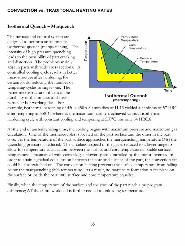
CONVECTION vs. TRADITONAL HEATING RATES
Isothermal Quench – Marquench
The furnace and control system are designed to perform an automatic isothermal quench (marquenching). The intensity of high pressure quenching leads to the possibility of part cracking and distortion. The problems mainly arise in parts with wide cross sections. A controlled cooling cycle results in better microstructure after hardening, for certain loads, reducing the number of tempering cycles to single one. The better microstructure influences the durability of the process tool steels, particular hot working dies. For example, isothermal hardening of 450 x 450 x 80 mm dies of H-13 yielded a hardness of 57 HRC after tempering at 550C, where as the maximum hardness achieved without isothermal hardening cycle with constant cooling and tempering at 550C was only 54 HRC.6
At the end of austenitenizing time, the cooling begins with maximum pressure and maximum gas circulation. One of the thermocouples is located on the part surface and the other in the part core. As the temperature of the part surface approaches the marquenching temperature (Ms) the quenching pressure is reduced. The circulation speed of the gas is reduced to a lower range to allow for temperature equalization between the surface and core temperatures. Stable surface temperature is maintained with veritable gas blower speed controlled by the motor inverter. In order to attain a gradual equalization between the core and surface of the part, the convection fan could be also switched on. The convection heating prevents the surface temperature from falling below the marquenching (Ms) temperature. As a result, no martensite formation takes place on the surface or inside the part until surface and core temperature equalize.
Finally, when the temperature of the surface and the core of the part reach a preprogram difference; T the entire workload is further cooled to unloading temperature.
65
66
LPC VACUUM CARBURIZING
Considering upstream and downstream costs, vacuum carburizing provides a total reduction of processing costs and is a natural fit in a lean manufacturing cell.
There is an increased interest in furnaces for vacuum carburizing due to the demand for products with the best overall metallurgical quality and lowest unit cost. Vacuum carburizing technology produces work with minimum distortion, the direct result of being cooled with gas. The surface metallurgy is superior because the carburization process is carried out in a vacuum environment. Vacuum furnaces systems provide “cold to cold” (cold work going in, cold work coming out) and fully automatic operation that reduces the amount of operator involvement, thus minimizing labor costs.
Vacuum furnace technology is a “green” manufacturing process with no negative impact on the environment.
This technology differs considerably from traditional gas carburizing both in the equipment used and in the process economy. This following presents aspects of vacuum carburizing technology that have an impact on process costs and quality improvements in the final product.
Vacuum carburizing is considerably faster than gas carburizing
Vacuum carburizing is characterized by an extraordinarily high coefficient of carbon transfer at the phase interface, which results in a high carbon transfer. In the initial phase of carburizing, for example, at a temperature of 1740°F (950°C), the carbon stream directed at the charge surface reaches the rate of 250 g/m2h. This means that, in the case of thin carburization layers, the process is considerably faster than the gas carburizing process. The advantage is smaller in the case of thick layers that exceed for example, .00315 inches (0.8 mm), where the carbon transfer is much more dependant on the diffusion coefficient (DC).
The vacuum carburizing process may easily be carried out even at temperatures of up to 1900°F (1050°C), within the natural temperature range of a vacuum furnace. The process temperature increases to 1700-1800°F (950-980°C), compared to traditional gas carburizing processes that typically operate within a temperature range of 1600-1700°F (880-930°C). Operating at higher temperatures results in shorter carburizing cycles due to the considerable increase of the diffusion coefficient (DC). Both the increased amount of carbon in the carburizing atmosphere, and faster diffusion (Dc) are responsible for the increase in vacuum carburizing efficiency when compared to the traditional gas carburizing.
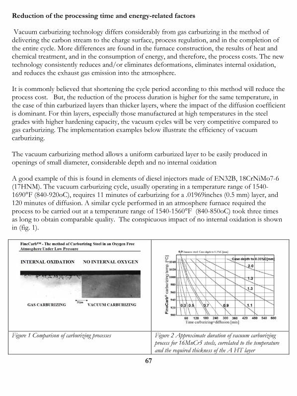
Reduction of the processing time and energy-related factors
Vacuum carburizing technology differs considerably from gas carburizing in the method of delivering the carbon stream to the charge surface, process regulation, and in the completion of the entire cycle. More differences are found in the furnace construction, the results of heat and chemical treatment, and in the consumption of energy, and therefore, the process costs. The new technology consistently reduces and/or eliminates deformations, eliminates internal oxidation, and reduces the exhaust gas emission into the atmosphere.
It is commonly believed that shortening the cycle period according to this method will reduce the process cost. But, the reduction of the process duration is higher for the same temperature, in the case of thin carburized layers than thicker layers, where the impact of the diffusion coefficient is dominant. For thin layers, especially those manufactured at high temperatures in the steel grades with higher hardening capacity, the vacuum cycles will be very competitive compared to gas carburizing. The implementation examples below illustrate the efficiency of vacuum carburizing.
The vacuum carburizing method allows a uniform carburized layer to be easily produced in openings of small diameter, considerable depth and no internal oxidation
A good example of this is found in elements of diesel injectors made of EN32B, 18CrNiMo7-6 (17HNM). The vacuum carburizing cycle, usually operating in a temperature range of 1540-1690°F (840-920oC), requires 11 minutes of carburizing for a .01969inches (0.5 mm) layer, and 120 minutes of diffusion. A similar cycle performed in an atmosphere furnace required the process to be carried out at a temperature range of 1540-1560°F (840-850oC) took three times as long to obtain comparable quality. The conspicuous impact of no internal oxidation is shown in (fig. 1).
Figure 1 Comparison of carburizing processes Figure 2 Approximate duration of vacuum carburizing
process for 16MnCr5 steels, correlated to the temperature and the required thickness of the A HT layer
67
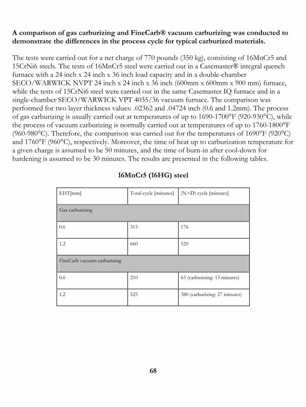
68
A comparison of gas carburizing and FineCarb® vacuum carburizing was conducted to demonstrate the differences in the process cycle for typical carburized materials.
The tests were carried out for a net charge of 770 pounds (350 kg), consisting of 16MnCr5 and 15CrNi6 steels. The tests of 16MnCr5 steel were carried out in a Casemaster® integral quench furnace with a 24 inch x 24 inch x 36 inch load capacity and in a double-chamber SECO/WARWICK NVPT 24 inch x 24 inch x 36 inch (600mm x 600mm x 900 mm) furnace, while the tests of 15CrNi6 steel were carried out in the same Casemaster IQ furnace and in a single-chamber SECO/WARWICK VPT 4035/36 vacuum furnace. The comparison was performed for two layer thickness values: .02362 and .04724 inch (0.6 and 1.2mm). The process of gas carburizing is usually carried out at temperatures of up to 1690-1700°F (920-930°C), while the process of vacuum carburizing is normally carried out at temperatures of up to 1760-1800°F (960-980°C). Therefore, the comparison was carried out for the temperatures of 1690°F (920°C) and 1760°F (960°C), respectively. Moreover, the time of heat up to carburization temperature for a given charge is assumed to be 50 minutes, and the time of burn-in after cool-down for hardening is assumed to be 30 minutes. The results are presented in the following tables.
16MnCr5 (16HG) steel
EHT[mm] Total cycle [minutes] (N+D) cycle [minutes]
Gas carburizing
0.6 315 176
1.2 660 520
FineCarb vacuum carburizing
0.6 210 63 (carburizing: 13 minutes)
1.2 525 380 (carburizing: 27 minutes)
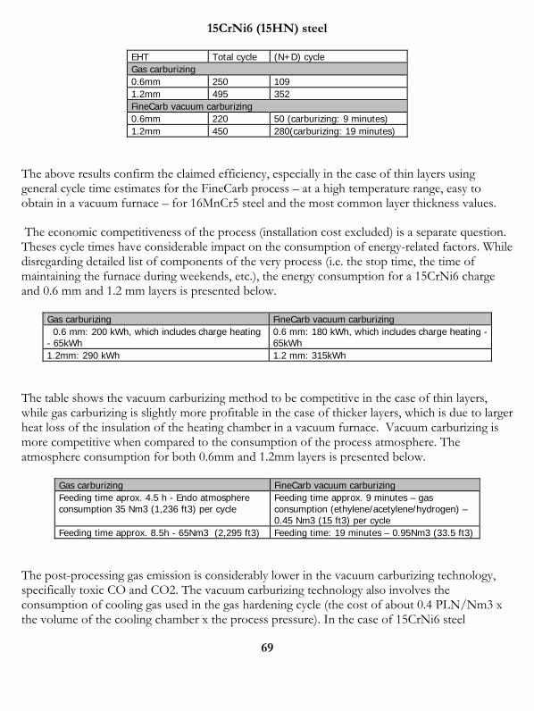
69
15CrNi6 (15HN) steel
EHT Total cycle (N+D) cycle Gas carburizing 0.6mm 250 109 1.2mm 495 352 FineCarb vacuum carburizing 0.6mm 220 50 (carburizing: 9 minutes) 1.2mm 450 280(carburizing: 19 minutes)
The above results confirm the claimed efficiency, especially in the case of thin layers using general cycle time estimates for the FineCarb process – at a high temperature range, easy to obtain in a vacuum furnace – for 16MnCr5 steel and the most common layer thickness values.
The economic competitiveness of the process (installation cost excluded) is a separate question. Theses cycle times have considerable impact on the consumption of energy-related factors. While disregarding detailed list of components of the very process (i.e. the stop time, the time of maintaining the furnace during weekends, etc.), the energy consumption for a 15CrNi6 charge and 0.6 mm and 1.2 mm layers is presented below.
Gas carburizing FineCarb vacuum carburizing 0.6 mm: 200 kWh, which includes charge heating - 65kWh
0.6 mm: 180 kWh, which includes charge heating - 65kWh
1.2mm: 290 kWh 1.2 mm: 315kWh
The table shows the vacuum carburizing method to be competitive in the case of thin layers, while gas carburizing is slightly more profitable in the case of thicker layers, which is due to larger heat loss of the insulation of the heating chamber in a vacuum furnace. Vacuum carburizing is more competitive when compared to the consumption of the process atmosphere. The atmosphere consumption for both 0.6mm and 1.2mm layers is presented below.
Gas carburizing FineCarb vacuum carburizing Feeding time aprox. 4.5 h - Endo atmosphere consumption 35 Nm3 (1,236 ft3) per cycle
Feeding time approx. 9 minutes – gas consumption (ethylene/acetylene/hydrogen) – 0.45 Nm3 (15 ft3) per cycle
Feeding time approx. 8.5h - 65Nm3 (2,295 ft3) Feeding time: 19 minutes – 0.95Nm3 (33.5 ft3)
The post-processing gas emission is considerably lower in the vacuum carburizing technology, specifically toxic CO and CO2. The vacuum carburizing technology also involves the consumption of cooling gas used in the gas hardening cycle (the cost of about 0.4 PLN/Nm3 x the volume of the cooling chamber x the process pressure). In the case of 15CrNi6 steel
70
hardened in VPT 4035/36 furnace at the pressure of 10 bars, the cost of used Nitrogen is about $6.30 (€5.30) per cycle (Prices based on 4th quarter 2005 costs in Eastern Europe). When module furnaces are used and the demand for the cooling gas is much higher, a recycling system can be designed to improve the efficiency to 98%, which further reduces costs.
The trials were performed in a vacuum carburizing furnace updated with the latest measurement technology. These modifications allowed the chemical composition of output gasses to be constantly registered on the run. As the proportions of the atmosphere feed were known, it was possible to determine the most probable directions of chemical reactions occurring during the process, and to determine their kinetics
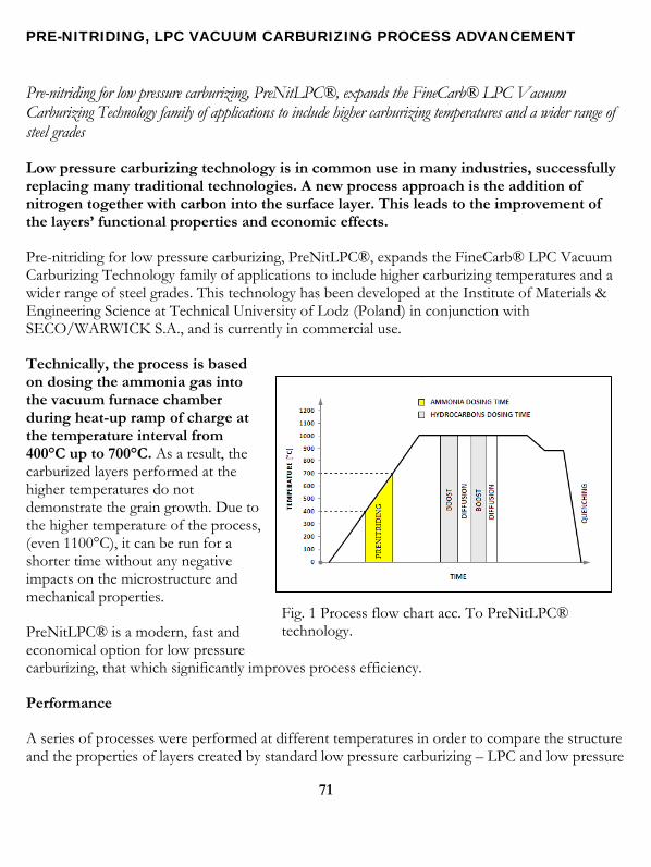
PRE-NITRIDING, LPC VACUUM CARBURIZING PROCESS ADVANCEMENT
Pre-nitriding for low pressure carburizing, PreNitLPC®, expands the FineCarb® LPC Vacuum Carburizing Technology family of applications to include higher carburizing temperatures and a wider range of steel grades
Low pressure carburizing technology is in common use in many industries, successfully replacing many traditional technologies. A new process approach is the addition of nitrogen together with carbon into the surface layer. This leads to the improvement of the layers’ functional properties and economic effects.
Pre-nitriding for low pressure carburizing, PreNitLPC®, expands the FineCarb® LPC Vacuum Carburizing Technology family of applications to include higher carburizing temperatures and a wider range of steel grades. This technology has been developed at the Institute of Materials & Engineering Science at Technical University of Lodz (Poland) in conjunction with SECO/WARWICK S.A., and is currently in commercial use.
Technically, the process is based on dosing the ammonia gas into the vacuum furnace chamber during heat-up ramp of charge at the temperature interval from 400°C up to 700°C. As a result, the carburized layers performed at the higher temperatures do not demonstrate the grain growth. Due to the higher temperature of the process, (even 1100°C), it can be run for a shorter time without any negative impacts on the microstructure and mechanical properties.
PreNitLPC® is a modern, fast and economical option for low pressure carburizing, that which significantly improves process efficiency.
Fig. 1 Process flow chart acc. To PreNitLPC® technology.
Performance
A series of processes were performed at different temperatures in order to compare the structure and the properties of layers created by standard low pressure carburizing – LPC and low pressure
71
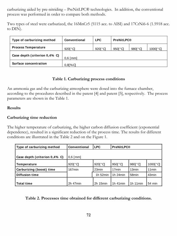
72
carburizing aided by pre-nitriding – PreNitLPC® technologies. In addition, the conventional process was performed in order to compare both methods.
Two types of steel were carburized, the 16MnCr5 (5115 acc. to AISI) and 17CrNi6-6 (1.5918 acc. to DIN).
Type of carburizing method Conventional LPC PreNitLPC®
Process Temperature 920[°C] 920[°C] 950[°C] 980[°C] 1000[°C]
Case depth (criterion 0,4% C) 0,6 [mm]
Surface concentration 0,8[%C]
Table 1. Carburizing process conditions
An ammonia gas and the carburizing atmosphere were dosed into the furnace chamber, according to the procedures described in the patent [4] and patent [5], respectively. The process parameters are shown in the Table 1.
Results
Carburizing time reduction
The higher temperature of carburizing, the higher carbon diffusion coefficient (exponential dependence), resulted in a significant reduction of the process time. The results for different conditions are illustrated in the Table 2 and on the Figure 1.
Type of carburizing method Conventional LPC PreNitLPC®
Case depth (criterion 0,4% C) 0,6 [mm]
Temperature 920[°C] 920[°C] 950[°C] 980[°C] 1000[°C]
Carburizing (boost) time 167min 23min 17min 13min 11min
Diffusion time 1h 52min 1h 24min 58min 43min
Total time 2h 47min 2h 15min 1h 41min 1h 11min 54 min
Table 2. Processes time obtained for different carburizing conditions.
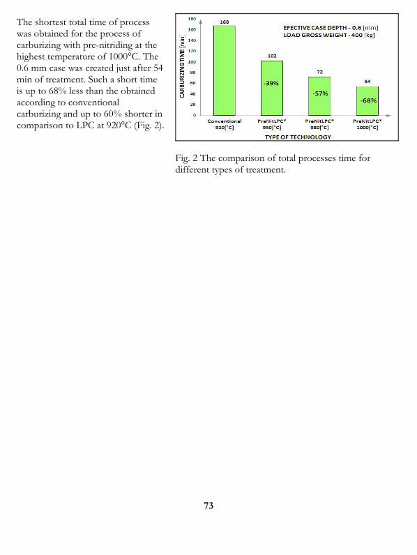
The shortest total time of process was obtained for the process of carburizing with pre-nitriding at the highest temperature of 1000°C. The 0.6 mm case was created just after 54 min of treatment. Such a short time is up to 68% less than the obtained according to conventional carburizing and up to 60% shorter in comparison to LPC at 920°C (Fig. 2).
Fig. 2 The comparison of total processes time for different types of treatment.
73
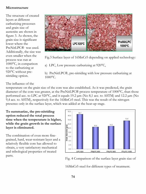
Microstructure
The structure of created layers at different carburizing processes and grain size of austenite are shown in figure 3. As shown, the grain size is significant lower where the PreNitLPC® was used. Additionally, the size was even smaller when the process was run at 1000°C, in comparison to the carburizing at 920°C without pre-nitriding option.
Fig.3 Surface layer of 16MnCr5 depending on applied technology:
a) LPC, Low pressure carburizing at 920°C,
b) PreNitLPC®, pre-nitriding with low pressure carburizing at 1000°C.
The influence of the temperature on the grain size of the core was also established. As it was predicted, the grain diameter of the core was greater, at the PreNitLPC® process temperature of 1000°C, than those performed acc. to LPC at 920°C, and it equals 19.2 µm (No 8,1 acc. to ASTM) and 12.2 µm (No 9,4 acc. to ASTM), respectively for the 16MnCr5 steel. This was the result of the nitrogen presence only in the surface layer, which was added at the heat-up stage.
Fig. 4 Comparison of the surface layer grain size of
To summarize, the pre-nitriding option reduced the total process time when the temperature is higher, while the grain growth in the surface layer is eliminated.
The combination of even more fine-grained, hard, wear-resistant layer and a relatively flexible core has allowed to obtain, a very satisfactory mechanical and tribological properties of treated parts.
16MnCr5 steel for different types of treatment.
74
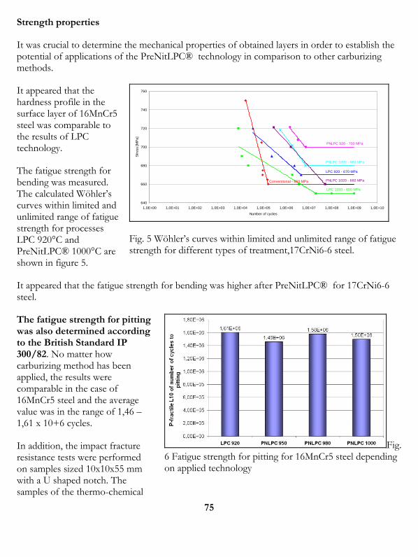
Strength properties
It was crucial to determine the mechanical properties of obtained layers in order to establish the potential of applications of the PreNitLPC® technology in comparison to other carburizing methods.
It appeared that the hardness profile in the surface layer of 16MnCr5 steel was comparable to the results of LPC technology.
640
660
680
700
720
740
760
1,0E+00 1,0E+01 1,0E+02 1,0E+03 1,0E+04 1,0E+05 1,0E+06 1,0E+07 1,0E+08 1,0E+09 1,0E+10
Number of cycles
Str
ess
[M
Pa
]
LPC 920 - 670 MPa
LPC 1000 - 650 MPa
PNLPC 920 - 700 MPa
PNLPC 1000 - 680 MPa
PNLPC 1020 - 660 MPa
75
The fatigue strength for bending was measured. The calculated Wöhler’s curves within limited and unlimited range of fatigue strength for processes LPC 920°C and PreNitLPC® 1000°C are shown in figure 5.
Conventional - 660 MPa
Fig. 5 Wöhler’s curves within limited and unlimited range of fatigue strength for different types of treatment,17CrNi6-6 steel.
It appeared that the fatigue strength for bending was higher after PreNitLPC® for 17CrNi6-6 steel.
Fig. 6 Fatigue strength for pitting for 16MnCr5 steel depending on applied technology
The fatigue strength for pitting was also determined according to the British Standard IP 300/82. No matter how carburizing method has been applied, the results were comparable in the case of 16MnCr5 steel and the average value was in the range of 1,46 – 1,61 x 10+6 cycles.
In addition, the impact fracture resistance tests were performed on samples sized 10x10x55 mm with a U shaped notch. The samples of the thermo-chemical
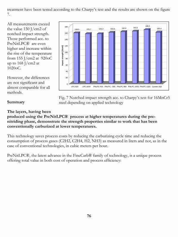
treatment have been tested according to the Charpy’s test and the results are shown on the figure 7.
All measurements exceed the value 150 J/cm2 of notched impact strength. Those performed acc. to PreNitLPC® are even higher and increase within the rise of the temperature from 155 J/cm2 at 920oC up to 168 J/cm2 at 1020oC.
158,5 155,7 155,3 159,6 162,0 163,6168,3
160,4
0
20
40
60
80
100
120
140
160
180
Imp
act
str
en
gth
[J/
cm
2]
LPC 920 LPC 1000 PNLPC 920 PNLPC - 950 PNLPC 980 PNLPC 1000 PNLPC 1020 Conven 920
However, the differences are not significant and almost comparable for all methods.
Fig. 7 Notched impact strength acc. to Charpy’s test for 16MnCr5 steel depending on applied technology Summary
The layers, having been produced using the PreNitLPC® process at higher temperatures during the pre-nitriding phase, demonstrate the strength properties similar to work that has been conventionally carburized at lower temperatures.
This technology saves process costs by reducing the carburizing cycle time and reducing the consumption of process gases (C2H2, C2H4, H2, NH3) as measured in liters and not, as in the case of conventional technologies, in cubic meters per hour.
PreNitLPC®, the latest advance in the FineCarb® family of technology, is a unique process offering total value in both cost of operation and process efficiency:
76

Reduce Carburizing Cycle Time
77
Lower Process Cost No Internal Oxidation Excellent Uniformity Optimum carbon
penetration No CO2 emissions Environmentally-friendly
For every 100 processes (i.e. for 0,6mm ECD) according to traditional carburizing methods (Fig. 8), PreNitLPC® technology can offer you up to 40% in increased process efficiency.
Fig. 7 Efficiency increase depending on Effective Case Depth
Optimum carbon penetration allows for the efficient heat treatment of complex shapes and the densely packed loads with superior case uniformity. This technology is adaptable to both new and existing furnaces equipped with FineCarb® technology and may be equipped with either an oil or gas quench.
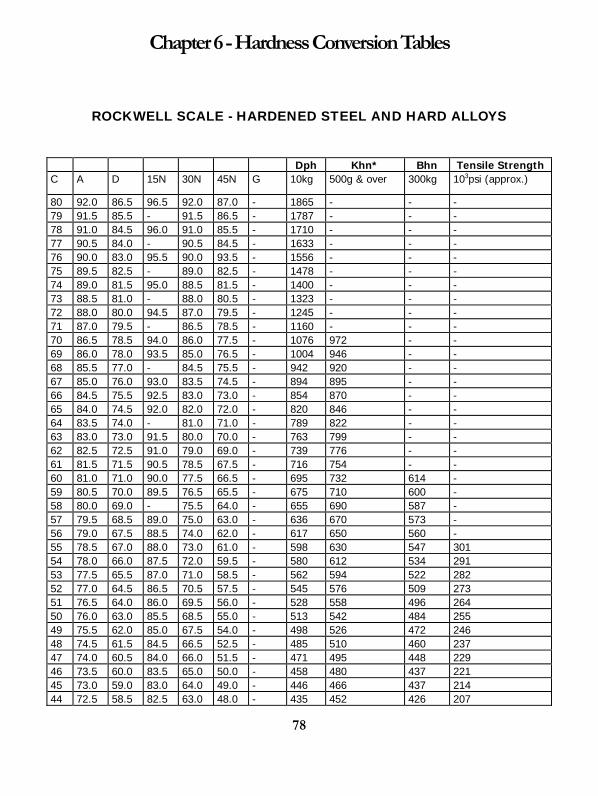
78
Chapter 6 - Hardness Conversion Tables
ROCKWELL SCALE - HARDENED STEEL AND HARD ALLOYS
Dph Khn* Bhn Tensile Strength C A D 15N 30N 45N G 10kg 500g & over 300kg 103psi (approx.)
80 92.0 86.5 96.5 92.0 87.0 - 1865 - - - 79 91.5 85.5 - 91.5 86.5 - 1787 - - - 78 91.0 84.5 96.0 91.0 85.5 - 1710 - - - 77 90.5 84.0 - 90.5 84.5 - 1633 - - - 76 90.0 83.0 95.5 90.0 93.5 - 1556 - - - 75 89.5 82.5 - 89.0 82.5 - 1478 - - - 74 89.0 81.5 95.0 88.5 81.5 - 1400 - - - 73 88.5 81.0 - 88.0 80.5 - 1323 - - - 72 88.0 80.0 94.5 87.0 79.5 - 1245 - - - 71 87.0 79.5 - 86.5 78.5 - 1160 - - - 70 86.5 78.5 94.0 86.0 77.5 - 1076 972 - - 69 86.0 78.0 93.5 85.0 76.5 - 1004 946 - - 68 85.5 77.0 - 84.5 75.5 - 942 920 - - 67 85.0 76.0 93.0 83.5 74.5 - 894 895 - - 66 84.5 75.5 92.5 83.0 73.0 - 854 870 - - 65 84.0 74.5 92.0 82.0 72.0 - 820 846 - - 64 83.5 74.0 - 81.0 71.0 - 789 822 - - 63 83.0 73.0 91.5 80.0 70.0 - 763 799 - - 62 82.5 72.5 91.0 79.0 69.0 - 739 776 - - 61 81.5 71.5 90.5 78.5 67.5 - 716 754 - - 60 81.0 71.0 90.0 77.5 66.5 - 695 732 614 - 59 80.5 70.0 89.5 76.5 65.5 - 675 710 600 - 58 80.0 69.0 - 75.5 64.0 - 655 690 587 - 57 79.5 68.5 89.0 75.0 63.0 - 636 670 573 - 56 79.0 67.5 88.5 74.0 62.0 - 617 650 560 - 55 78.5 67.0 88.0 73.0 61.0 - 598 630 547 301 54 78.0 66.0 87.5 72.0 59.5 - 580 612 534 291 53 77.5 65.5 87.0 71.0 58.5 - 562 594 522 282 52 77.0 64.5 86.5 70.5 57.5 - 545 576 509 273 51 76.5 64.0 86.0 69.5 56.0 - 528 558 496 264 50 76.0 63.0 85.5 68.5 55.0 - 513 542 484 255 49 75.5 62.0 85.0 67.5 54.0 - 498 526 472 246 48 74.5 61.5 84.5 66.5 52.5 - 485 510 460 237 47 74.0 60.5 84.0 66.0 51.5 - 471 495 448 229 46 73.5 60.0 83.5 65.0 50.0 - 458 480 437 221 45 73.0 59.0 83.0 64.0 49.0 - 446 466 437 214 44 72.5 58.5 82.5 63.0 48.0 - 435 452 426 207
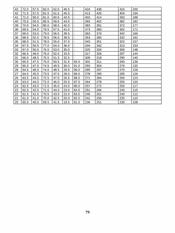
79
43 72.0 57.5 82.0 62.0 46.5 - 424 438 415 200 42 71.5 57.0 81.5 61.5 45.5 - 413 426 404 194 41 71.0 56.0 81.0 60.5 44.5 - 403 414 393 188 40 70.5 55.5 80.5 59.5 43.0 - 393 402 382 182 39 70.0 54.5 80.0 58.5 42.0 - 383 391 372 177 38 69.5 54.0 79.5 57.5 41.0 - 373 380 362 171 37 69.0 53.0 79.0 56.5 39.5 - 363 370 342 166 36 68.5 52.5 78.5 56.0 38.5 - 353 360 332 162 35 68.0 51.5 78.0 55.0 37.0 - 343 351 322 157 34 67.5 50.5 77.0 54.0 36.0 - 334 342 313 153 33 67.0 50.0 76.5 53.0 35.0 - 325 334 305 148 32 66.5 49.0 76.0 52.0 33.5 - 317 326 297 144 31 66.0 48.5 75.5 51.5 32.5 - 309 318 290 140 30 65.5 47.5 75.0 50.5 31.5 92.0 301 311 283 136 29 65.0 47.0 74.5 49.5 30.0 91.0 293 304 276 132 28 64.5 46.0 74.0 48.5 29.0 90.0 285 297 270 129 27 64.0 45.5 73.5 47.5 28.0 89.0 278 290 265 126 26 63.5 44.5 72.5 47.0 26.5 88.0 271 284 260 123 25 63.0 44.0 72.0 46.0 25.5 87.0 264 278 255 120 24 62.5 43.0 71.5 45.0 24.0 86.0 257 272 250 117 23 62.0 42.5 71.0 44.0 23.0 84.5 251 266 245 115 22 61.5 41.5 70.5 43.0 22.0 83.5 246 261 240 112 21 61.0 41.0 70.0 42.5 20.0 82.5 241 256 235 110 20 60.5 40.0 69.5 41.5 19.5 81.0 236 251 230 108
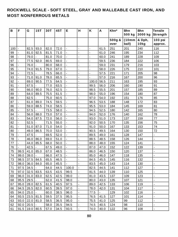
80
ROCKWELL SCALE - SOFT STEEL, GRAY AND MALLEABLE CAST IRON, AND MOST NONFERROUS METALS
B F G 15T 30T 45T E H K A Khn* Bhn 500 kg
Bhn 3000 kg
Tensile Strength
500g & over
(10mm ball)
& Dph, 10kg
103 psi approx.
100 - 82.5 93.0 82.0 72.0 - - - 61.5 251 201 240 116 99 - 81.0 92.5 81.5 71.0 - - - 61.0 246 195 234 112 98 - 79.0 - 81.0 70.0 - - - 60.0 241 189 228 109 97 - 77.5 92.0 80.5 69.0 - - - 59.5 236 184 222 106 96 - 76.0 - 80.0 68.0 - - - 59.0 231 179 216 103 95 - 74.0 91.5 79.0 67.0 - - - 58.0 226 175 210 101 94 - 72.5 - 78.5 66.0 - - - 57.5 221 171 205 98 93 - 71.0 91.0 78.0 65.5 - - - 57.0 216 167 200 96 92 - 69.0 90.5 77.5 64.5 - - 100.0 56.5 211 163 195 93 91 - 67.5 - 77.0 63.5 - - 99.5 56.0 206 160 190 91 90 - 66.0 90.0 76.0 62.5 - - 98.5 55.5 201 157 185 89 89 - 64.0 89.5 75.5 61.5 - - 98.0 55.0 196 154 180 87 88 - 62.5 - 75.0 60.5 - - 97.0 54.0 192 151 176 85 87 - 61.0 89.0 74.5 59.5 - - 96.5 53.5 188 148 172 83 86 - 59.0 88.5 74.0 58.5 - - 95.5 53.0 184 145 169 81 85 - 57.5 - 73.5 58.0 - - 94.5 52.5 180 142 165 80 84 - 56.0 88.0 73.0 57.0 - - 94.0 52.0 176 140 162 78 83 - 54.0 87.5 72.0 56.0 - - 93.0 51.0 173 137 159 77 82 - 52.5 - 71.5 55.0 - - 92.0 50.5 170 135 156 75 81 - 51.0 87.0 71.0 54.0 - - 91.0 50.0 167 133 153 74 80 - 49.0 86.5 70.0 53.0 - - 90.5 49.5 164 130 150 72 79 - 47.5 - 69.5 52.0 - - 89.5 49.0 161 128 147 - 78 - 46.0 86.0 69.0 51.0 - - 88.5 48.5 158 126 144 - 77 - 44.0 85.5 68.0 50.0 - - 88.0 48.0 155 124 141 - 76 - 42.5 - 67.5 49.0 - - 87.0 47.0 152 122 139 - 75 99.5 41.0 85.0 67.0 48.5 - - 86.0 46.5 150 120 137 - 74 99.0 39.0 - 66.0 47.5 - - 85.0 46.0 147 118 135 - 73 98.5 37.5 84.5 65.5 46.5 - - 84.5 45.5 145 116 132 - 72 98.0 36.0 84.0 65.0 45.5 - - 83.5 45.0 143 114 130 - 71 97.5 34.5 - 64.0 44.5 100.0 - 82.5 44.5 141 112 127 - 70 97.0 32.5 83.5 63.5 43.5 99.5 - 81.5 44.0 139 110 125 - 69 96.0 31.0 83.0 62.5 42.5 99.0 - 81.0 43.5 137 109 123 - 68 95.5 29.5 - 62.0 41.5 98.0 - 80.0 43.0 135 107 121 - 67 95.0 28.0 82.5 61.5 40.5 97.5 - 89.0 42.5 133 106 119 - 66 94.5 26.5 82.0 60.5 39.5 97.0 - 78.0 42.0 131 104 117 - 65 94.0 25.0 - 60.0 38.5 96.0 - 77.5 - 129 102 116 - 64 93.5 23.5 81.5 59.5 37.5 95.5 - 76.5 41.5 127 101 114 - 63 93.0 22.0 81.0 58.5 36.5 95.0 - 75.5 41.0 125 99 112 - 62 92.0 20.5 - 58.0 35.5 94.5 - 74.5 40.5 124 98 110 - 61 91.5 19.0 80.5 57.0 34.5 93.5 - 74.0 40.0 122 96 108 -
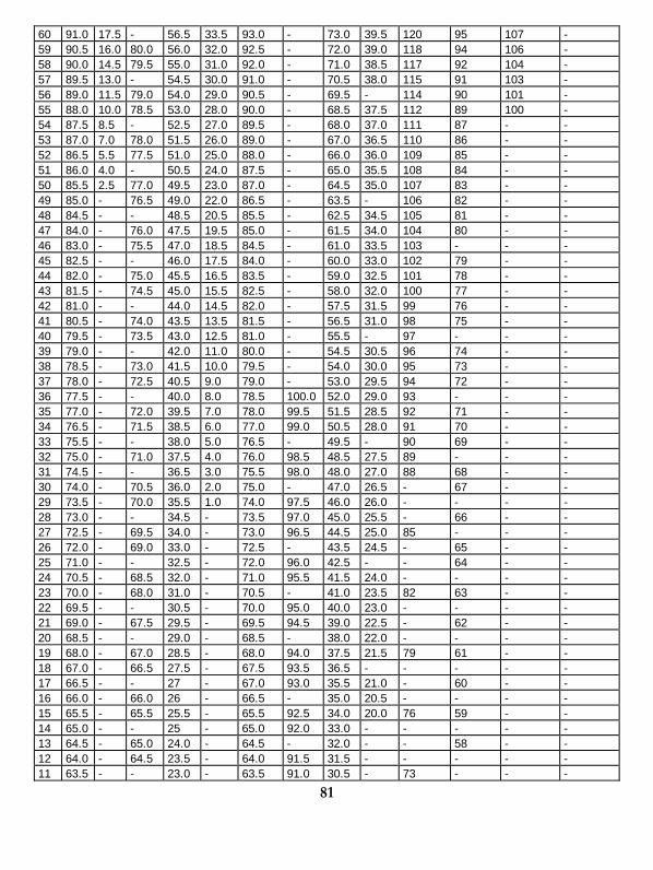
81
60 91.0 17.5 - 56.5 33.5 93.0 - 73.0 39.5 120 95 107 - 59 90.5 16.0 80.0 56.0 32.0 92.5 - 72.0 39.0 118 94 106 - 58 90.0 14.5 79.5 55.0 31.0 92.0 - 71.0 38.5 117 92 104 - 57 89.5 13.0 - 54.5 30.0 91.0 - 70.5 38.0 115 91 103 - 56 89.0 11.5 79.0 54.0 29.0 90.5 - 69.5 - 114 90 101 - 55 88.0 10.0 78.5 53.0 28.0 90.0 - 68.5 37.5 112 89 100 - 54 87.5 8.5 - 52.5 27.0 89.5 - 68.0 37.0 111 87 - - 53 87.0 7.0 78.0 51.5 26.0 89.0 - 67.0 36.5 110 86 - - 52 86.5 5.5 77.5 51.0 25.0 88.0 - 66.0 36.0 109 85 - - 51 86.0 4.0 - 50.5 24.0 87.5 - 65.0 35.5 108 84 - - 50 85.5 2.5 77.0 49.5 23.0 87.0 - 64.5 35.0 107 83 - - 49 85.0 - 76.5 49.0 22.0 86.5 - 63.5 - 106 82 - - 48 84.5 - - 48.5 20.5 85.5 - 62.5 34.5 105 81 - - 47 84.0 - 76.0 47.5 19.5 85.0 - 61.5 34.0 104 80 - - 46 83.0 - 75.5 47.0 18.5 84.5 - 61.0 33.5 103 - - - 45 82.5 - - 46.0 17.5 84.0 - 60.0 33.0 102 79 - - 44 82.0 - 75.0 45.5 16.5 83.5 - 59.0 32.5 101 78 - - 43 81.5 - 74.5 45.0 15.5 82.5 - 58.0 32.0 100 77 - - 42 81.0 - - 44.0 14.5 82.0 - 57.5 31.5 99 76 - - 41 80.5 - 74.0 43.5 13.5 81.5 - 56.5 31.0 98 75 - - 40 79.5 - 73.5 43.0 12.5 81.0 - 55.5 - 97 - - - 39 79.0 - - 42.0 11.0 80.0 - 54.5 30.5 96 74 - - 38 78.5 - 73.0 41.5 10.0 79.5 - 54.0 30.0 95 73 - - 37 78.0 - 72.5 40.5 9.0 79.0 - 53.0 29.5 94 72 - - 36 77.5 - - 40.0 8.0 78.5 100.0 52.0 29.0 93 - - - 35 77.0 - 72.0 39.5 7.0 78.0 99.5 51.5 28.5 92 71 - - 34 76.5 - 71.5 38.5 6.0 77.0 99.0 50.5 28.0 91 70 - - 33 75.5 - - 38.0 5.0 76.5 - 49.5 - 90 69 - - 32 75.0 - 71.0 37.5 4.0 76.0 98.5 48.5 27.5 89 - - - 31 74.5 - - 36.5 3.0 75.5 98.0 48.0 27.0 88 68 - - 30 74.0 - 70.5 36.0 2.0 75.0 - 47.0 26.5 - 67 - - 29 73.5 - 70.0 35.5 1.0 74.0 97.5 46.0 26.0 - - - - 28 73.0 - - 34.5 - 73.5 97.0 45.0 25.5 - 66 - - 27 72.5 - 69.5 34.0 - 73.0 96.5 44.5 25.0 85 - - - 26 72.0 - 69.0 33.0 - 72.5 - 43.5 24.5 - 65 - - 25 71.0 - - 32.5 - 72.0 96.0 42.5 - - 64 - - 24 70.5 - 68.5 32.0 - 71.0 95.5 41.5 24.0 - - - - 23 70.0 - 68.0 31.0 - 70.5 - 41.0 23.5 82 63 - - 22 69.5 - - 30.5 - 70.0 95.0 40.0 23.0 - - - - 21 69.0 - 67.5 29.5 - 69.5 94.5 39.0 22.5 - 62 - - 20 68.5 - - 29.0 - 68.5 - 38.0 22.0 - - - - 19 68.0 - 67.0 28.5 - 68.0 94.0 37.5 21.5 79 61 - - 18 67.0 - 66.5 27.5 - 67.5 93.5 36.5 - - - - - 17 66.5 - - 27 - 67.0 93.0 35.5 21.0 - 60 - - 16 66.0 - 66.0 26 - 66.5 - 35.0 20.5 - - - - 15 65.5 - 65.5 25.5 - 65.5 92.5 34.0 20.0 76 59 - - 14 65.0 - - 25 - 65.0 92.0 33.0 - - - - - 13 64.5 - 65.0 24.0 - 64.5 - 32.0 - - 58 - - 12 64.0 - 64.5 23.5 - 64.0 91.5 31.5 - - - - - 11 63.5 - - 23.0 - 63.5 91.0 30.5 - 73 - - -
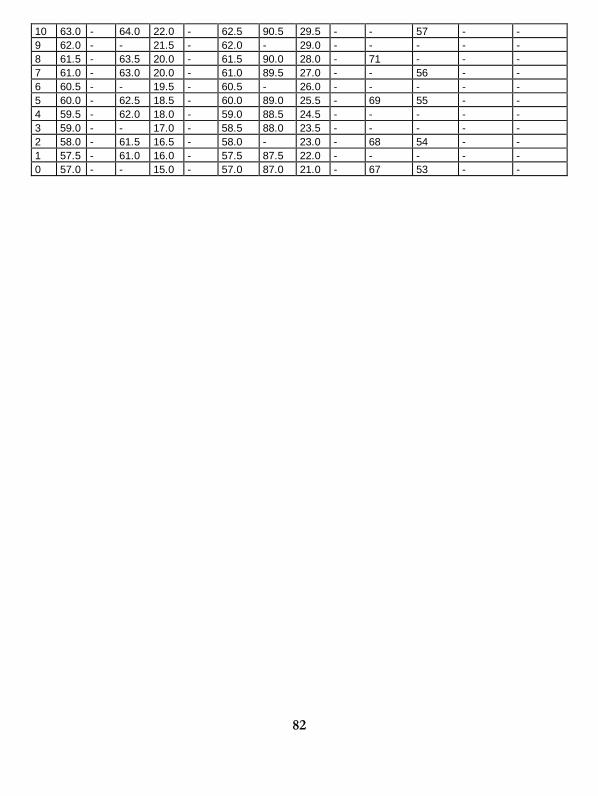
82
10 63.0 - 64.0 22.0 - 62.5 90.5 29.5 - - 57 - - 9 62.0 - - 21.5 - 62.0 - 29.0 - - - - - 8 61.5 - 63.5 20.0 - 61.5 90.0 28.0 - 71 - - - 7 61.0 - 63.0 20.0 - 61.0 89.5 27.0 - - 56 - - 6 60.5 - - 19.5 - 60.5 - 26.0 - - - - - 5 60.0 - 62.5 18.5 - 60.0 89.0 25.5 - 69 55 - - 4 59.5 - 62.0 18.0 - 59.0 88.5 24.5 - - - - - 3 59.0 - - 17.0 - 58.5 88.0 23.5 - - - - - 2 58.0 - 61.5 16.5 - 58.0 - 23.0 - 68 54 - - 1 57.5 - 61.0 16.0 - 57.5 87.5 22.0 - - - - - 0 57.0 - - 15.0 - 57.0 87.0 21.0 - 67 53 - -
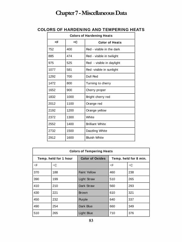
83
Chapter 7 - Miscellaneous Data
COLORS OF HARDENING AND TEMPERING HEATS Colors of Hardening Heats
ºF ºC Color of Heats
752 400 Red - visible in the dark
885 474 Red - visible in twilight
975 525 Red - visible in daylight
1077 581 Red -visible in sunlight
1292 700 Dull Red
1472 800 Turning to cherry
1652 900 Cherry proper
1832 1000 Bright cherry red
2012 1100 Orange red
2192 1200 Orange yellow
2372 1300 White
2552 1400 Brilliant White
2732 1500 Dazzling White
2912 1600 Bluish White
Colors of Tempering Heats
Temp. held for 1 hour Color of Oxides Temp. held for 8 min.
ºF ºC ºF ºC
370 188 Faint Yellow 460 238
390 199 Light Straw 510 265
410 210 Dark Straw 560 293
430 221 Brown 610 321
450 232 Purple 640 337
490 254 Dark Blue 660 349
510 265 Light Blue 710 376
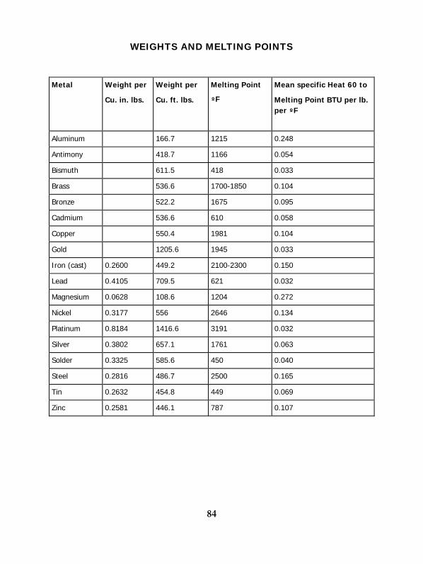
84
WEIGHTS AND MELTING POINTS
Metal Weight per
Cu. in. lbs.
Weight per
Cu. ft. lbs.
Melting Point
ºF
Mean specific Heat 60 to
Melting Point BTU per lb. per ºF
Aluminum 166.7 1215 0.248
Antimony 418.7 1166 0.054
Bismuth 611.5 418 0.033
Brass 536.6 1700-1850 0.104
Bronze 522.2 1675 0.095
Cadmium 536.6 610 0.058
Copper 550.4 1981 0.104
Gold 1205.6 1945 0.033
Iron (cast) 0.2600 449.2 2100-2300 0.150
Lead 0.4105 709.5 621 0.032
Magnesium 0.0628 108.6 1204 0.272
Nickel 0.3177 556 2646 0.134
Platinum 0.8184 1416.6 3191 0.032
Silver 0.3802 657.1 1761 0.063
Solder 0.3325 585.6 450 0.040
Steel 0.2816 486.7 2500 0.165
Tin 0.2632 454.8 449 0.069
Zinc 0.2581 446.1 787 0.107

TIME ALLOWANCES HEATING FOR HARDENING
According to tests made by the Carpenter Steel Company in the Service Bulletin, Volume 2, the center and surface of work reach the furnace temperature at the same time and accordingly the best method of determining time required to heat for hardening is by visual observation of the work actually coming up to heat, observing the following precautions:
1. Place the thermocouple directly behind the largest section of the work. 2. Judge temperature of actual work, not loose scale or corners, by looking through the
slightly open door of the furnace, not the peephole. 3. Allow approximately 5 minutes per inch of section for uniform heating after work
and thermocouple are apparently at heat (1400º to 1500º).
For a rough rule for calculating heating time, figure approximately on a heat penetration at the rate of 1/8” per 5 minutes or about 20 minutes per inch on round bars. For high speed steels in hardening temperature, total time is allowed at 4 to 6 minutes per inch of thickness but never long enough to “blister”. This table gives approximate rates for other shapes:
Long cylinder ( dia. = D ) 1
Long square ( D x D ) 1
Long rectangle ( D x 2D )
Sphere ( dia. = D ) 1.5
Cube ( D x D x D ) 1.5
Long rectangle ( D x 3D ) .6
Infinite plate ( very wide, thickness = D ) .5
Shapes Speed Factor
.7
85
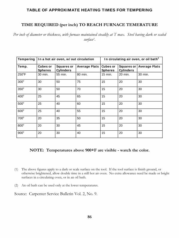
86
TABLE OF APPROXIMATE HEATING TIMES FOR TEMPERING
TIME REQUIRED (per inch) TO REACH FURNACE TEMERATURE
Per inch of diameter or thickness, with furnace maintained steadily at T max. Steel having dark or scaled surface1.
Tempering In a hot air oven, w/out circulation In circulating air oven, or oil bath2
Temp. Cubes or Spheres
Squares or Cylinders
Average Flats Cubes or Spheres
Squares or Cylinders
Average Flats
250oF 30 min. 55 min. 80 min. 15 min. 20 min. 30 min.
300o 30 50 75 15 20 30
350o 30 50 70 15 20 30
400o 25 45 65 15 20 30
500o 25 40 60 15 20 30
600o 25 40 55 15 20 30
700o 20 35 50 15 20 30
800o 20 30 45 15 20 30
900o 20 30 40 15 20 30
NOTE: Temperatures above 900ºF are visible - watch the color.
(1) The above figures apply to a dark or scale surface on the tool. If the tool surface is finish ground, or otherwise brightened, allow double time in a still hot air oven. No extra allowance need be made or bright surfaces in a circulating oven, or in an oil bath.
(2) An oil bath can be used only at the lower temperatures.
Source: Carpenter Service Bulletin Vol. 2, No. 9.
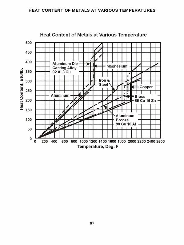
HEAT CONTENT OF METALS AT VARIOUS TEMPERATURES
87
88
COMPOSITION HARDNESS
Hardenability is a term used to designate that property of steel which determines the depth and distribution of hardness induced by quenching from the austenitizing temperature. Whereas the as-quenched surface hardness of a steel part is dependent primarily on carbon content and cooling rate, the depth to which a certain hardness level is maintained with given quenching conditions is a function of its hardenability. Hardenability is largely determined by the percentage of alloying elements present in the steel. Austenitic grain size, time and temperature during austenitizing, and prior microstructure also can have significant effects.
Hardenablility, determined by standard procedures described below, is constant for a given composition; whereas hardness will vary with the cooling rate. Thus, for a given composition, the hardness obtained at any location in a part will depend not only on carbon content and hardenability but also on the size and configuration of the part and the quenchant and quenching conditions used.
The hardenability required for a particular part depends on many factors, including size, design, and service stresses. For highly stressed parts, particularly those loaded principally in tension, the best combination of strength and toughness is attained by through hardening to a martensitic structure followed by adequate tempering. Quenching such parts to a minimum of 80% martensite is generally considered adequate. Carbon steel can be used for thin sections, but as section size increases, alloy steels of increasing hardenability are required. Where only moderate stresses are involved, quenching to a minimum of 50% martensite is sometimes appropriate.
In order to satisfy the stress loading requirements of a particular application, a carbon or alloy steel having the required hardenability must be selected. The usual practice is to select the most economical grade which can consistently meet the desired properties.
There are many applications where through-hardening is not necessary, or even desirable. For example, for parts which are stressed principally at or near the surface, or in which wear-resistance or resistance to shock loading are primary considerations, shallow-hardening steels or surface hardening treatments, as discussed below may be appropriate.
End-Quench Hardenability Testing
The most commonly used method of determining hardenability is the end-quench test developed by Jominy and Boegehold1.
In conducting the test, a 1-inch-round specimen 4 inches long is first normalized to eliminate the variable of prior microstructure, then heated uniformly to a standard austenitizing temperature.
89
The specimen is removed from the furnace, placed in a jig, and immediately end-quenched by a jet of water maintained at room temperature. The water contacts the end-face of the specimen without wetting the sides, and quenching is continued until the entire specimen has cooled.
Longitudinal flat surfaces are ground on opposite sides of the quenched specimen, and Rockwell C scale readings are taken at 16th-inch intervals for the first inch from the quenched end, and at greater intervals beyond that point until a hardness level of HRC 20 or a distance of 2 inches from the quenched end is reached.
A hardenability curve is usually plotted using Rockwell C readings as ordinates and distances from the quenched end as abscissas. Representative data have been accumulated for a variety of standard grades and are published by SAE and AISI as H-bands. These show graphically and in tabular form the high and low limits applicable to each grade. Steels specified to these limits are designated as H-grades.
(1) For a complete description of this test see the SAE Handbook or ASTM Designation A255.
ASTM: http://www.astm.org/BOOKSTORE/PUBS/1377.htm
SAE Handbook: http://www.sae.org/pubs/
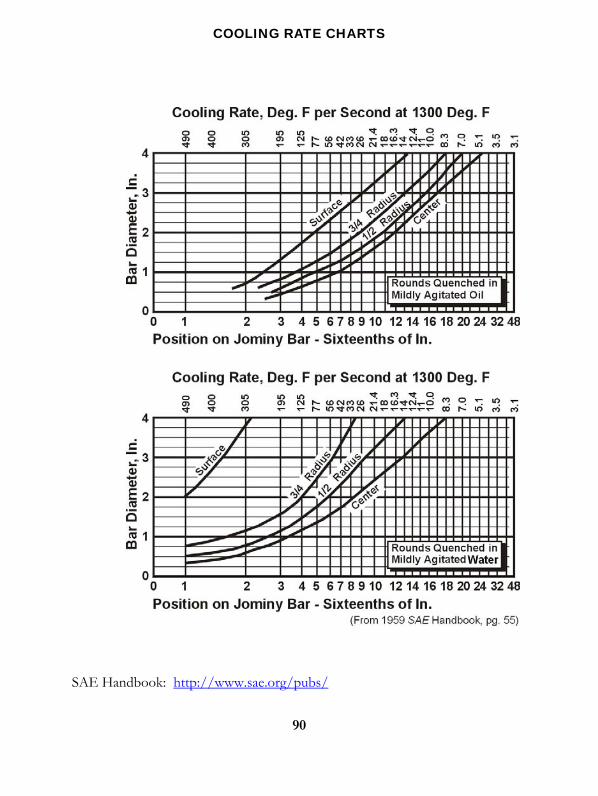
91
CALCULATION OF END-QUENCH HARDENABILITY BASED ON ANALYSIS
Since only the end of the specimen is quenched in this test, it is obvious that the cooling rate along the surface of the specimen decreases as the distance from the quenched end increases. Experiments have confirmed that the cooling rate at a given point along the bar can be correlated with the cooling rate at various locations on rounds of various sizes.
The following graphs show this correlation for surface, ¾ radius, ½ radius and center locations for rounds up to 4 inches in diameter quenched in mildly agitated oil and in mildly agitated water. Similar data are shown at the top of each H-Band as published by SAE and AISI. These values are not absolute, but are useful in determining the grades which may achieve a particular hardness at a specified location in a given section.
Calculation of End-Quench Hardenability Based on Analysis
It is sometimes desirable to predict the end-quench hardenability curve of a proposed analysis or of a commercial steel not available for testing.
The method1 described here affords a reasonably accurate means of calculating hardness at any Jominy location on a section of steel of known analysis and grain size. To illustrate this method, consider a heat of 8640 having a grain size of No. 8 at the quenching temperature and the analysis shown in step II, below.
STEP I. Determine the initial hardness (IH). This is the hardness at 1/16 inch on the end-quench specimen and is a function of the carbon content as illustrated by the graph below. The IH for .39% carbon is HRC 55.5.

(1) Based on the work of M.A. Grossman, AIME, February 1942, and J. Field, Metal Progress, March 1943.
MULTIPLYING FACTORS FOR CARBON PER GRAIN SIZE
STEP II. Calculate the ideal critical diameter (DI). This is the diameter of the largest round of the given analysis which will harden to 50% martensite at the center during an ideal quench. The DI is the product of the multiplying factors representing each element.
From the graphs below, find the multiplying factors for carbon at No. 8 grain size, and for the other elements:
C Mn Si Ni Cr Mo
Heat Analysis (%) .39 .91 .25 .54 .56 .20
Multiplying Factor .195 4.03 1.18 1.20 2.21 1.60
The product of these factors is 3.93 DI.
92

93
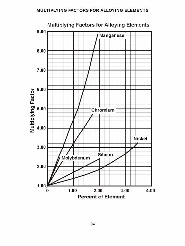
MULTIPLYING FACTORS FOR ALLOYING ELEMENTS
94
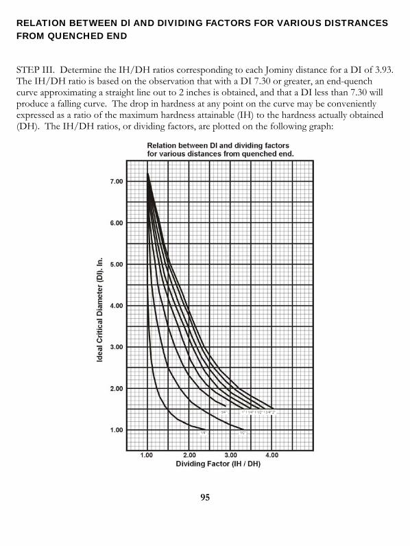
RELATION BETWEEN Dl AND DIVIDING FACTORS FOR VARIOUS DISTRANCES FROM QUENCHED END
STEP III. Determine the IH/DH ratios corresponding to each Jominy distance for a DI of 3.93. The IH/DH ratio is based on the observation that with a DI 7.30 or greater, an end-quench curve approximating a straight line out to 2 inches is obtained, and that a DI less than 7.30 will produce a falling curve. The drop in hardness at any point on the curve may be conveniently expressed as a ratio of the maximum hardness attainable (IH) to the hardness actually obtained (DH). The IH/DH ratios, or dividing factors, are plotted on the following graph:
95
96
COMPOSITION HARDNESS
STEP IV. Calculate the Rockwell C hardness for each distance by dividing the IH (55.5) by each respective dividing factor:
Distance, in: Dividing Factor Calculated HRC
1/16 - 55.5 ¼ 1.03 54 ½ 1.21 46 ¾ 1.41 39.5 1 1.61 34.5 1 ¼ 1.75 32 1 ½ 1.84 30 1 ¾ 1.92 29 2 1.96 28.5
Source: Bethlehem Steel Co., “Modern Steels and Their Properties,” Seventh Edition.
If the effect of various contained elements is known, it is possible to anticipate approximately the response of steel to heat treatment under identical conditions. Aside from the chemistry, the other characteristics of the steel developed by melting practice, rolling temperatures, etc., must be similar when comparing steels by this method.
Values which may be used for the various elements are: Carbon………….0.01% = 30 Chromium……...0.01%= 5 Manganese……..0.01% = 8 Vanadium………0.01%= 20 Phosphorus…….0.001% = 4 Molybdenum…...0.01%= 16 Sulfur…………..0.001% = 1 Tungsten………..0.01%= 4 Silicon………….0.01% = 5 Copper………….0.01%= 4 Nickel………….0.01% = 4
These factor figures have been found useful in comparing heats of steel containing the same elements. They however, are not infallible when comparing one type of steel with another, since the value of any of these alloying elements varies, depending on whether the effect is of a single element or the combined effect of several elements. This applies more particularly to alloy steels.
97
As an example of the application of this quick method, compare the hardness factors of AISI C1030 and AISI C1132 using the mean of the analysis range.
AISI C1030 AISIx1132
Carbon…….30x30= 900 Carbon……….30x30= 900
Manganese….75x8= 600 Manganese….150x8= 1200
Phosphorus…..23x4= 92 Phosphorus…..23x4= 92
Sulfur……….27x1= 27 Sulfur………112x1= 112
Silicon……....20x5= 100 Silicon…..…….20x5= 100
Hardness Factor = 1719 Hardness Factor = 2404
An arithmetical method for obtaining the approximate tensile strength of rolled carbon steel:
T.S. = C x 650 + M x 90 + M x C x 4 + P x 1000 + 38800
Source: Bethlehem Steel Co. Catalog 107.
NOTE: A more theoretical description of Hardening may be found in ASM Handbook, Vol. 4. http://products.asminternational.org/hbk/index.jsp
98
QUENCHING NOTES
As proper quenching is recognized as one of the most important steps in heat treating, the following is condensed from the Carpenter Service Bulletin on this important subject.
A still, fresh water quenching bath is not an ideal quenching medium because of the large quantity of gas dissolved which settles in the form of bubbles on the surface of the tool, especially in holes or recesses, forming soft spots which are quite likely to crack or badly weaken the tool.
A still, brine quenching bath is much better than fresh water as the salt dissolved in the water prevents the water from dissolving atmospheric gases and accordingly the brine “takes hold” and “wets” the tool all over immediately, so that quenching proceeds uniformly. Brine also throws scale better than fresh water and usually yields cleaner tools. Ordinarily the most satisfactory brine bath will contain between 5% and 10% of salt.
A still, 5% caustic soda quenching solution is one of the fastest and most efficient quenching solution is one of the fastest and most efficient quenching baths except that it is corrosive to clothing and hands and is rarely necessary for most heat treating work. Bath temperatures should be between 70º and 100ºF.
Oil for quenching should have a high flash-point, low viscosity, constant composition and should be maintained at temperatures from 140ºF. to 160ºF.
In flush-quenching, water is just as good as brine as gas pockets cannot form on the work.
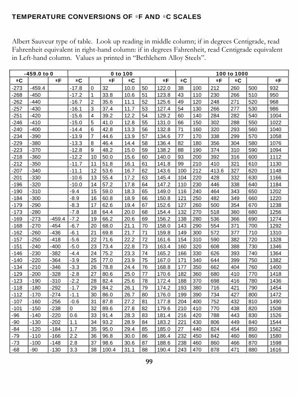
99
TEMPERATURE CONVERSIONS OF ºF AND ºC SCALES
Albert Sauveur type of table. Look up reading in middle column; if in degrees Centigrade, read Fahrenheit equivalent in right-hand column: if in degrees Fahrenheit, read Centigrade equivalent in Left-hand column. Values as printed in “Bethlehem Alloy Steels”.
-459.0 to 0 0 to 100 100 to 1000 ºC ºF ºC ºF ºC ºF ºC ºF ºC ºF
-273 -459.4 -17.8 0 32 10.0 50 122.0 38 100 212 260 500 932 -268 -450 -17.2 1 33.8 10.6 51 123.8 43 110 230 266 510 950 -262 -440 -16.7 2 35.6 11.1 52 125.6 49 120 248 271 520 968 -257 -430 -16.1 3 37.4 11.7 53 127.4 54 130 266 277 530 986 -251 -420 -15.6 4 39.2 12.2 54 129.2 60 140 284 282 540 1004 -246 -410 -15.0 5 41.0 12.8 55 131.0 66 150 302 288 550 1022 -240 -400 -14.4 6 42.8 13.3 56 132.8 71 160 320 293 560 1040 -234 -390 -13.9 7 44.6 13.9 57 134.6 77 170 338 299 570 1058 -229 -380 -13.3 8 46.4 14.4 58 136.4 82 180 356 304 580 1076 -223 -370 -12.8 9 48.2 15.0 59 138.2 88 190 374 310 590 1094 -218 -360 -12.2 10 50.0 15.6 60 140.0 93 200 392 316 600 1112 -212 -350 -11.7 11 51.8 16.1 61 141.8 99 210 410 321 610 1130 -207 -340 -11.1 12 53.6 16.7 62 143.6 100 212 413.6 327 620 1148 -201 -330 -10.6 13 55.4 17.2 63 145.4 104 220 428 332 630 1166 -196 -320 -10.0 14 57.2 17.8 64 147.2 110 230 446 338 640 1184 -190 -310 -9.4 15 59.0 18.3 65 149.0 116 240 464 343 650 1202 -184 -300 -8.9 16 60.8 18.9 66 150.8 121 250 482 349 660 1220 -179 -290 -8.3 17 62.6 19.4 67 152.6 127 260 500 354 670 1238 -173 -280 -7.8 18 64.4 20.0 68 154.4 132 270 518 360 680 1256 -169 -273 -459.4 -7.2 19 66.2 20.6 69 156.2 138 280 536 366 690 1274 -168 -270 -454 -6.7 20 68.0 21.1 70 158.0 143 290 554 371 700 1292 -162 -260 -436 -6.1 21 69.8 21.7 71 159.8 149 300 572 377 710 1310 -157 -250 -418 -5.6 22 71.6 22.2 72 161.6 154 310 590 382 720 1328 -151 -240 -400 -5.0 23 73.4 22.8 73 163.4 160 320 608 388 730 1346 -146 -230 -382 -4.4 24 75.2 23.3 74 165.2 166 330 626 393 740 1364 -140 -220 -364 -3.9 25 77.0 23.9 75 167.0 171 340 644 399 750 1382 -134 -210 -346 -3.3 26 78.8 24.4 76 168.8 177 350 662 404 760 1400 -129 -200 -328 -2.8 27 80.6 25.0 77 170.6 182 360 680 410 770 1418 -123 -190 -310 -2.2 28 82.4 25.6 78 172.4 188 370 698 416 780 1436 -118 -180 -292 -1.7 29 84.2 26.1 79 174.2 193 380 716 421 790 1454 -112 -170 -274 -1.1 30 86.0 26.7 80 176.0 199 390 734 427 800 1472 -107 -160 -256 -0.6 31 87.8 27.2 81 177.8 204 400 752 432 810 1490 -101 -150 -238 0 32 89.6 27.8 82 179.6 210 410 770 438 820 1508 -96 -140 -220 0.6 33 91.4 28.3 83 181.4 216 420 788 443 830 1526 -90 -130 -202 1.1 34 93.2 28.9 84 183.2 221 430 806 449 840 1544 -84 -120 -184 1.7 35 95.0 29.4 85 185.0 27 440 824 454 850 1562 -79 -110 -166 2.2 36 96.8 30.0 86 186.4 232 450 842 460 860 1580 -73 -100 -148 2.8 37 98.6 30.6 87 188.6 238 460 860 466 870 1598 -68 -90 -130 3.3 38 100.4 31.1 88 190.4 243 470 878 471 880 1616
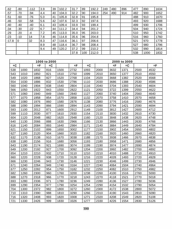
100
-62 -80 -112 3.9 39 102.2 31.7 89 192.2 249 480 896 477 890 1634 -57 -70 -94 4.4 40 104.0 32.2 90 194.0 254 490 914 482 900 1652 -51 -60 -76 5.0 41 105.8 32.8 91 195.8 488 910 1670 -46 -50 -58 5.6 42 107.6 32.3 92 197.6 493 920 1688 -40 -40 -40 6.1 43 109.4 33.9 93 199.4 499 930 1706 -34 -30 -22 6.7 44 111.2 34.4 94 201.2 504 940 1724 -29 -20 -4 7.2 45 113.0 35.0 95 203.0 510 950 1742 -23 -10 14 7.8 46 114.8 35.6 96 204.8 516 960 1760 -17.8 0 32 8.3 47 116.6 36.1 97 206.6 521 970 1778 8.9 48 118.4 36.7 98 208.4 527 980 1796 9.4 49 120.2 37.2 99 210.2 532 990 1814 37.8 100 212.0 538 1000 1832
1000 to 2000 2000 to 3000
ºC ºF ºC ºF ºC ºF ºC ºF 538 1000 1832 816 1500 2732 1093 2000 3632 1371 2500 4532 543 1010 1850 821 1510 2750 1099 2010 3650 1377 2510 4550 549 1020 1868 827 1520 2768 1104 2020 3668 1382 2520 4568 554 1030 1886 832 1530 2786 1110 2030 3686 1388 2530 4586 560 1040 1904 838 1540 2804 1116 2040 3704 1393 2540 4604 566 1050 1922 843 1550 2822 1121 2050 3722 1399 2550 4622 571 1060 1940 849 1560 2840 1127 2060 3740 1404 2560 4640 577 1070 1958 854 1570 2858 1132 2070 3758 1410 2570 4658 582 1080 1976 860 1580 2876 1138 2080 3776 1416 2580 4676 588 1090 1994 866 1590 2894 1143 2090 3794 1421 2590 4694 593 1100 2012 871 1600 2912 1149 2100 3812 1427 2600 4712 599 1110 2030 877 1610 2930 1154 2110 3830 1432 2610 4730 604 1120 2048 882 1620 2948 1160 2120 3848 1438 2620 4748 640 1130 2066 888 1630 2966 1166 2130 3866 1443 2630 4766 616 1140 2084 893 1640 2984 1171 2140 3884 1449 2640 4784 621 1150 2102 899 1650 3002 1177 2150 3902 1454 2650 4802 627 1160 2120 904 1660 3020 1182 2160 3920 1460 2660 4820 632 1170 2138 910 1670 3038 1188 2170 3938 1466 2670 4838 638 1180 2156 916 1680 3056 1193 2180 3958 1471 2680 4856 643 1190 2174 921 1690 3074 1199 2190 3974 1477 2690 4874 649 1200 2192 927 1700 3092 1204 2200 3992 1482 2700 4892 654 1210 2210 932 1710 3110 1210 2210 4010 1488 2710 4910 660 1220 2228 938 1720 3128 1216 2220 4028 1493 2720 4928 666 1230 2246 943 1730 3146 1221 2230 4046 1499 2730 4946 671 1240 2264 949 1740 3164 1227 2240 4064 1504 2740 4964 677 1250 2282 954 1750 3182 1232 2250 4082 1510 2750 4982 682 1260 2300 960 1760 3200 1238 2260 4100 1516 2760 5000 688 1270 2318 966 1770 3218 1243 2270 4118 1521 2770 5018 693 1280 2336 971 1780 3236 1249 2280 4136 1527 2780 5036 699 1290 2354 977 1790 3254 1254 2290 4154 1532 2790 5054 704 1300 2372 982 1800 3272 1260 2300 4172 1538 2800 5072 710 1310 2390 988 1810 3290 1266 2310 4190 1543 2810 5090 716 1320 2408 993 1820 3308 1271 2320 4208 1549 2820 5108 721 1330 2426 999 1830 3326 1277 2330 4226 1554 2830 5126
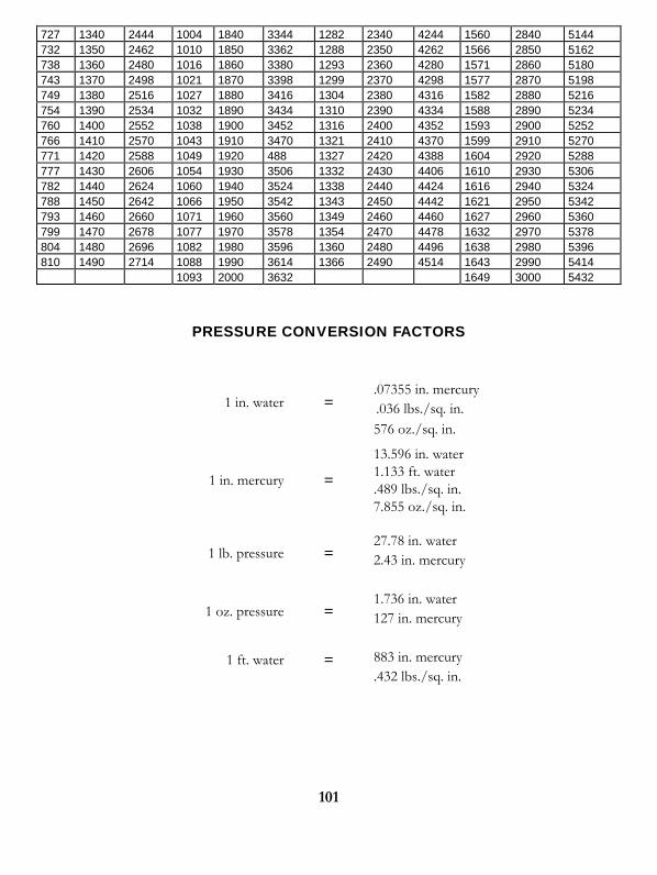
101
727 1340 2444 1004 1840 3344 1282 2340 4244 1560 2840 5144 732 1350 2462 1010 1850 3362 1288 2350 4262 1566 2850 5162 738 1360 2480 1016 1860 3380 1293 2360 4280 1571 2860 5180 743 1370 2498 1021 1870 3398 1299 2370 4298 1577 2870 5198 749 1380 2516 1027 1880 3416 1304 2380 4316 1582 2880 5216 754 1390 2534 1032 1890 3434 1310 2390 4334 1588 2890 5234 760 1400 2552 1038 1900 3452 1316 2400 4352 1593 2900 5252 766 1410 2570 1043 1910 3470 1321 2410 4370 1599 2910 5270 771 1420 2588 1049 1920 488 1327 2420 4388 1604 2920 5288 777 1430 2606 1054 1930 3506 1332 2430 4406 1610 2930 5306 782 1440 2624 1060 1940 3524 1338 2440 4424 1616 2940 5324 788 1450 2642 1066 1950 3542 1343 2450 4442 1621 2950 5342 793 1460 2660 1071 1960 3560 1349 2460 4460 1627 2960 5360 799 1470 2678 1077 1970 3578 1354 2470 4478 1632 2970 5378 804 1480 2696 1082 1980 3596 1360 2480 4496 1638 2980 5396 810 1490 2714 1088 1990 3614 1366 2490 4514 1643 2990 5414 1093 2000 3632 1649 3000 5432
PRESSURE CONVERSION FACTORS
1 in. water = .07355 in. mercury .036 lbs./sq. in. 576 oz./sq. in.
1 in. mercury =
13.596 in. water 1.133 ft. water .489 lbs./sq. in. 7.855 oz./sq. in.
1 lb. pressure = 27.78 in. water 2.43 in. mercury
1 oz. pressure = 1.736 in. water 127 in. mercury
1 ft. water = 883 in. mercury .432 lbs./sq. in.
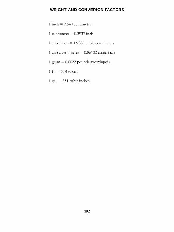
102
WEIGHT AND CONVERION FACTORS
1 inch = 2.540 centimeter
1 centimeter = 0.3937 inch
1 cubic inch = 16.387 cubic centimeters
1 cubic centimeter = 0.06102 cubic inch
1 gram = 0.0022 pounds avoirdupois
1 ft. = 30.480 cm.
1 gal. = 231 cubic inches
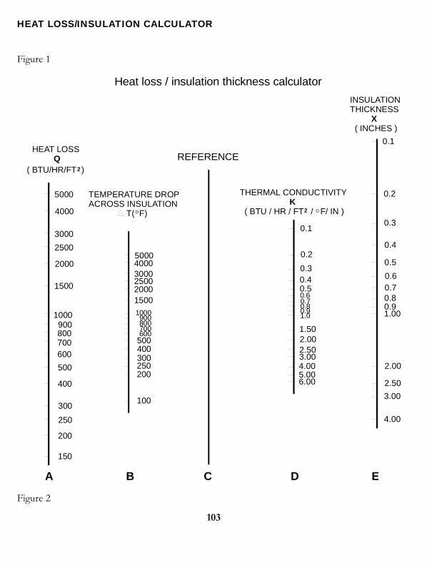
HEAT LOSS/INSULATION CALCULATOR
Figure 1
5000
5000
4000
4000
3000
3000
2500
2500
2000
20001500
1500
1000 1000
900 900
800 800
700
700
600
600
500
500
400
400
300
300
250
250
200
200
150
100
HEAT LOSS Q
( BTU/HR/FT )2
2
TEMPERATURE DROPACROSS INSULATION T( F)O O
THERMAL CONDUCTIVITY ( BTU / HR / FT / F/ IN )
K
0.1
0.1
0.2
0.2
0.3
0.3
0.4
0.4
0.5
0.5
0.60.70.80.91.00
2.00
2.50
3.00
4.00
0.60.70.80.91.0
1.502.002.503.004.005.006.00
REFERENCE
INSULATIONTHICKNESS ( INCHES )
X
Heat loss / insulation thickness calculator
A B C D E
Figure 2
103
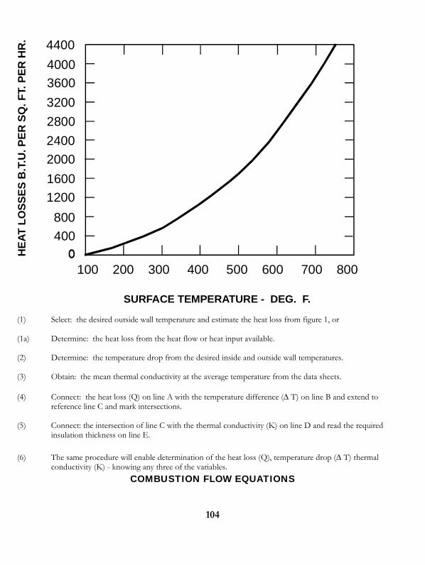
4400
3600
3200
2800
2400
2000
1600
1200
800
400
4000
100 200 300 400 500 600 700 800
HE
AT
LO
SS
ES
B.T
.U. P
ER
SQ
. F
T. P
ER
HR
.
SURFACE TEMPERATURE - DEG. F.
(1) Select: the desired outside wall temperature and estimate the heat loss from figure 1, or (1a) Determine: the heat loss from the heat flow or heat input available. (2) Determine: the temperature drop from the desired inside and outside wall temperatures. (3) Obtain: the mean thermal conductivity at the average temperature from the data sheets. (4) Connect: the heat loss (Q) on line A with the temperature difference ( T) on line B and extend to
reference line C and mark intersections. (5) Connect: the intersection of line C with the thermal conductivity (K) on line D and read the required
insulation thickness on line E. (6) The same procedure will enable determination of the heat loss (Q), temperature drop ( T) thermal
conductivity (K) - knowing any three of the variables.
COMBUSTION FLOW EQUATIONS
104
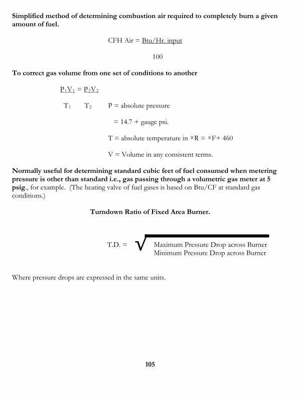
Simplified method of determining combustion air required to completely burn a given amount of fuel.
CFH Air = Btu/Hr. input
100
To correct gas volume from one set of conditions to another
P1V1 = P2V2
T1 T2 P = absolute pressure
= 14.7 + gauge psi.
T = absolute temperature in ºR = ºF+ 460
V = Volume in any consistent terms.
Normally useful for determining standard cubic feet of fuel consumed when metering pressure is other than standard i.e., gas passing through a volumetric gas meter at 5 psig., for example. (The heating valve of fuel gases is based on Btu/CF at standard gas conditions.)
Turndown Ratio of Fixed Area Burner.
√T.D. = Maximum Pressure Drop across Burner Minimum Pressure Drop across Burner
Where pressure drops are expressed in the same units.
105
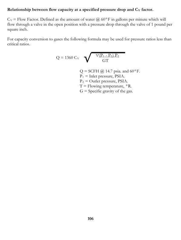
Relationship between flow capacity at a specified pressure drop and CV factor.
CV = Flow Factor. Defined as the amount of water @ 60°F in gallons per minute which will flow through a valve in the open position with a pressure drop through the valve of 1 pound per square inch.
For capacity conversion to gases the following formula may be used for pressure ratios less than critical ratios.
Q = 1360 CV √ v(P1 - P2) P2 GT
Q = SCFH @ 14.7 psia. and 60°F. P1 = Inlet pressure, PSIA. P2 = Outlet pressure, PSIA. T = Flowing temperature, °R. G = Specific gravity of the gas.
106
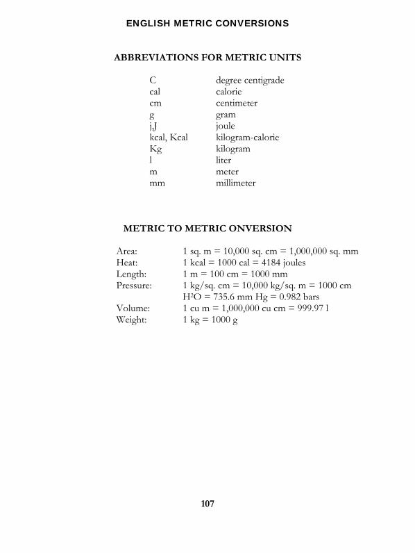
107
ENGLISH METRIC CONVERSIONS
ABBREVIATIONS FOR METRIC UNITS
C degree centigrade cal calorie cm centimeter g gram j,J joule kcal, Kcal kilogram-calorie Kg kilogram l liter m meter mm millimeter
METRIC TO METRIC ONVERSION
Area: 1 sq. m = 10,000 sq. cm = 1,000,000 sq. mm Heat: 1 kcal = 1000 cal = 4184 joules Length: 1 m = 100 cm = 1000 mm Pressure: 1 kg/sq. cm = 10,000 kg/sq. m = 1000 cm H2O = 735.6 mm Hg = 0.982 bars Volume: 1 cu m = 1,000,000 cu cm = 999.97 l Weight: 1 kg = 1000 g
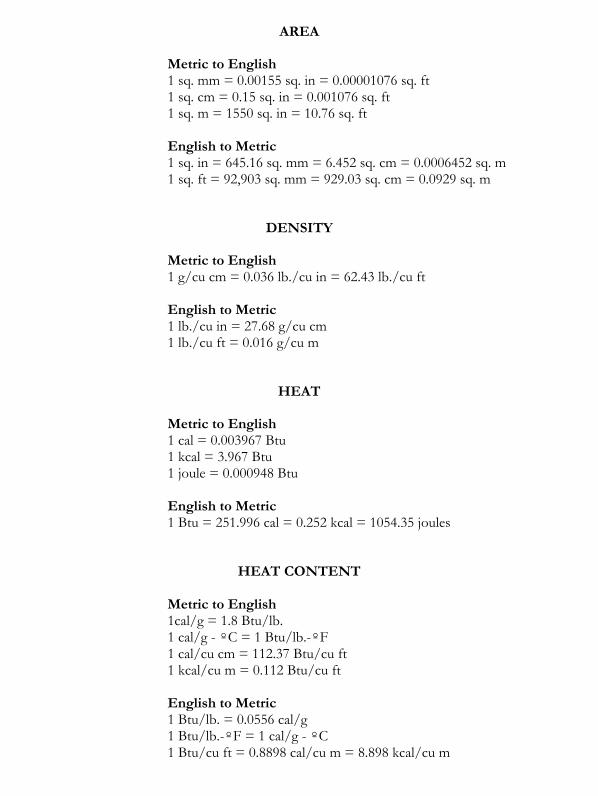
AREA
Metric to English 1 sq. mm = 0.00155 sq. in = 0.00001076 sq. ft 1 sq. cm = 0.15 sq. in = 0.001076 sq. ft 1 sq. m = 1550 sq. in = 10.76 sq. ft
English to Metric 1 sq. in = 645.16 sq. mm = 6.452 sq. cm = 0.0006452 sq. m 1 sq. ft = 92,903 sq. mm = 929.03 sq. cm = 0.0929 sq. m
DENSITY
Metric to English 1 g/cu cm = 0.036 lb./cu in = 62.43 lb./cu ft English to Metric 1 lb./cu in = 27.68 g/cu cm 1 lb./cu ft = 0.016 g/cu m
HEAT
Metric to English 1 cal = 0.003967 Btu 1 kcal = 3.967 Btu 1 joule = 0.000948 Btu English to Metric 1 Btu = 251.996 cal = 0.252 kcal = 1054.35 joules
HEAT CONTENT
Metric to English 1cal/g = 1.8 Btu/lb. 1 cal/g - ºC = 1 Btu/lb.-ºF 1 cal/cu cm = 112.37 Btu/cu ft 1 kcal/cu m = 0.112 Btu/cu ft English to Metric 1 Btu/lb. = 0.0556 cal/g 1 Btu/lb.-ºF = 1 cal/g - ºC 1 Btu/cu ft = 0.8898 cal/cu m = 8.898 kcal/cu m
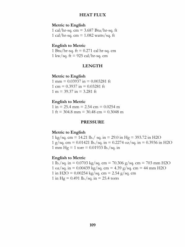
109
HEAT FLUX
Metric to English 1 cal/hr-sq. cm = 3.687 Btu/hr-sq. ft 1 cal/hr-sq. cm = 1.082 watts/sq. ft English to Metric 1 Btu/hr-sq. ft = 0.271 cal hr-sq. cm 1 kw/sq. ft = 925 cal/hr-sq. cm
LENGTH
Metric to English 1 mm = 0.03937 in = 0.003281 ft 1 cm = 0.3937 in = 0.03281 ft 1 m = 39.37 in = 3.281 ft English to Metric 1 in = 25.4 mm = 2.54 cm = 0.0254 m 1 ft = 304.8 mm = 30.48 cm = 0.3048 m
PRESSURE
Metric to English 1 kg/sq. cm = 14.21 lb./ sq. in = 29.0 in Hg = 393.72 in H2O 1 g/sq. cm = 0.01421 lb./sq. in = 0.2274 oz/sq. in = 0.3936 in H2O 1 mm Hg = 1 torr = 0.01933 lb./sq. in English to Metric 1 lb./sq. in = 0.0703 kg/sq. cm = 70.306 g/sq. cm = 703 mm H2O 1 oz/sq. in = 0.00439 kg/sq. cm = 4.39 g/sq. cm = 44 mm H2O 1 in H2O = 0.00254 kg/sq. cm = 2.54 g/sq. cm 1 in Hg = 0.491 lb./sq. in = 25.4 torrs
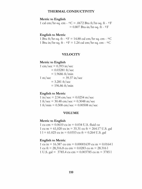
110
THERMAL CONDUCTIVITY
Metric to English 1 cal cm/hr-sq. cm - ºC = .0672 Btu ft/hr-sq. ft - ºF = 0.807 Btu-in/hr-sq. ft - ºF English to Metric 1 Btu ft/hr-sq. ft - ºF = 14.88 cal cm/hr sq. cm - ºC 1 Btu in/hr-sq. ft - ºF = 1.24 cal cm/hr-sq. cm - ºC
VELOCITY
Metric to English 1 cm/sec = 0.393 in/sec = 0.03281 ft/sec = 1.9686 ft/min 1 m/sec = 39.37 in/sec = 3.281 ft/sec = 196.86 ft/min
English to Metric 1 in/sec = 2.54 cm/sec = 0.0254 m/sec 1 ft/sec = 30.48 cm/sec = 0.3048 m/sec 1 ft/min = 0.508 cm/sec = 0.00508 m/sec
VOLUME
Metric to English 1 cu cm = 0.0610 cu in = 0.034 U.S. fluid oz 1 cu m = 61,020 cu in = 35.31 cu ft = 264.17 U.S. gal 1 l = 61.025 cu in = 0.0353 cu ft = 0.264 U.S. gal English to Metric 1 cu in = 16.387 cu cm = 0.00001639 cu m = 0.0164 l 1 cu ft = 28,316.8 cu cm = 0.0283 cu m = 28.316 l 1 U.S. gal = 3785.4 cu cm = 0.003785 cu m = 3785 l

111
WEIGHT
Metric to English 1 g = 0.035 oz avdp 1 kg = 35.27 oz avdp = 2.204 lb. avdp English to Metric 1 oz avdp = 28.35 g = 0.02835 kg 1 lb. avdp = 453.59 g = 0.4536 kg
TEMPERATURE
ºC = 5/9 (ºF-32) ºF = (9/5 ºC) + 32 ºK = ºC + 273.15 ºR = ºF + 459.67
AREA
MULTIPLY BY TO OBTAIN square inch square centimeter square decimeter circular mil square foot
6.4516 0.0645 1,273,240 0.1550 0.0010764 15.500 0.0000007854 0.0929
square centimeter square decimeter circular mil square inch square foot square inch square inch square meter
MASS
MULTIPLY BY TO OBTAIN ounce (Av) gram pound kilogram
28.3495 0.03527 0.002205 0.453592 2.20462
gram ounce (Av) pound (Av) kilogram pound (Av)
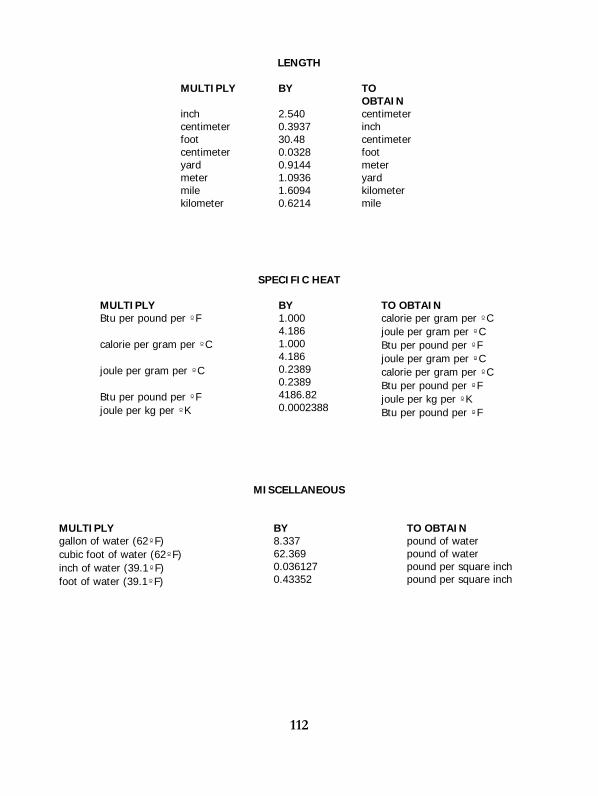
112
LENGTH
MULTIPLY BY TO OBTAIN
inch centimeter foot centimeter yard meter mile kilometer
2.540 0.3937 30.48 0.0328 0.9144 1.0936 1.6094 0.6214
centimeter inch centimeter foot meter yard kilometer mile
SPECIFIC HEAT
MULTIPLY BY TO OBTAIN Btu per pound per ºF calorie per gram per ºC joule per gram per ºC Btu per pound per ºF joule per kg per ºK
1.000 4.186 1.000 4.186 0.2389 0.2389 4186.82 0.0002388
calorie per gram per ºC joule per gram per ºC Btu per pound per ºF joule per gram per ºC calorie per gram per ºC Btu per pound per ºF joule per kg per ºK Btu per pound per ºF
MISCELLANEOUS
MULTIPLY BY TO OBTAIN gallon of water (62ºF) cubic foot of water (62ºF) inch of water (39.1ºF) foot of water (39.1ºF)
8.337 62.369 0.036127 0.43352
pound of water pound of water pound per square inch pound per square inch
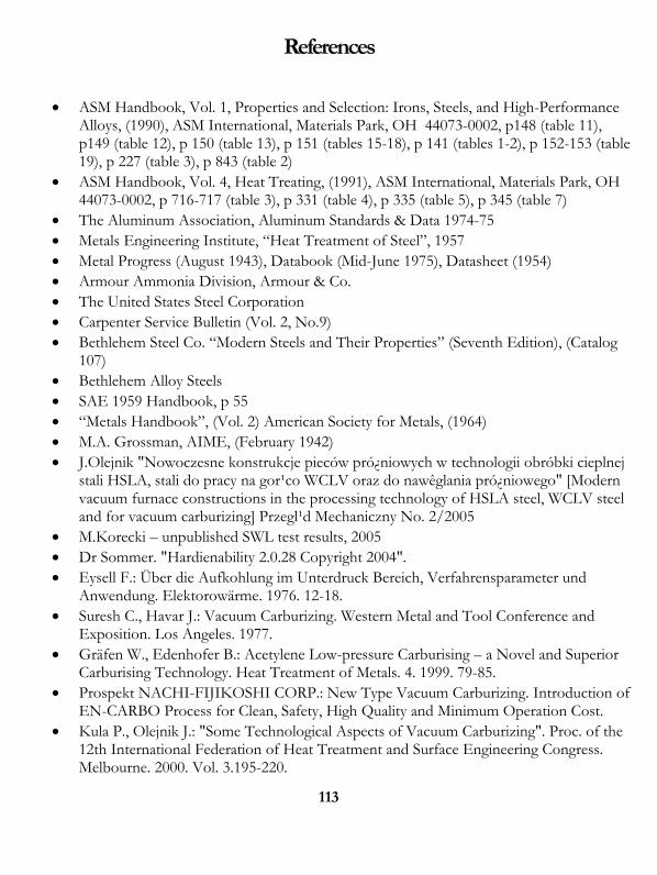
113
References
ASM Handbook, Vol. 1, Properties and Selection: Irons, Steels, and High-Performance Alloys, (1990), ASM International, Materials Park, OH 44073-0002, p148 (table 11), p149 (table 12), p 150 (table 13), p 151 (tables 15-18), p 141 (tables 1-2), p 152-153 (table 19), p 227 (table 3), p 843 (table 2)
ASM Handbook, Vol. 4, Heat Treating, (1991), ASM International, Materials Park, OH 44073-0002, p 716-717 (table 3), p 331 (table 4), p 335 (table 5), p 345 (table 7)
The Aluminum Association, Aluminum Standards & Data 1974-75 Metals Engineering Institute, “Heat Treatment of Steel”, 1957 Metal Progress (August 1943), Databook (Mid-June 1975), Datasheet (1954) Armour Ammonia Division, Armour & Co. The United States Steel Corporation Carpenter Service Bulletin (Vol. 2, No.9) Bethlehem Steel Co. “Modern Steels and Their Properties” (Seventh Edition), (Catalog
107) Bethlehem Alloy Steels SAE 1959 Handbook, p 55 “Metals Handbook”, (Vol. 2) American Society for Metals, (1964) M.A. Grossman, AIME, (February 1942) J.Olejnik "Nowoczesne konstrukcje pieców pró¿niowych w technologii obróbki cieplnej
stali HSLA, stali do pracy na gor¹co WCLV oraz do nawêglania pró¿niowego" [Modern vacuum furnace constructions in the processing technology of HSLA steel, WCLV steel and for vacuum carburizing] Przegl¹d Mechaniczny No. 2/2005
M.Korecki – unpublished SWL test results, 2005 Dr Sommer. "Hardienability 2.0.28 Copyright 2004". Eysell F.: Über die Aufkohlung im Unterdruck Bereich, Verfahrensparameter und
Anwendung. Elektorowärme. 1976. 12-18. Suresh C., Havar J.: Vacuum Carburizing. Western Metal and Tool Conference and
Exposition. Los Angeles. 1977. Gräfen W., Edenhofer B.: Acetylene Low-pressure Carburising – a Novel and Superior
Carburising Technology. Heat Treatment of Metals. 4. 1999. 79-85. Prospekt NACHI-FIJIKOSHI CORP.: New Type Vacuum Carburizing. Introduction of
EN-CARBO Process for Clean, Safety, High Quality and Minimum Operation Cost. Kula P., Olejnik J.: "Some Technological Aspects of Vacuum Carburizing". Proc. of the
12th International Federation of Heat Treatment and Surface Engineering Congress. Melbourne. 2000. Vol. 3.195-220.

114
Kula P., Olejnik P., Kowalewski J.: "A New Vacuum Carburizing Technology". Heat Treatment Progress. 2-3. 2001. 57-60.
P – 356754 – Mixture for pressure carburizing. E. Yagassaki, R.I. Masel w J.J. Spivey, S.K. Agrawal (Editors), Specialist Periodical
Reports: Catalysis Royal Soc. Chem., London, 1994, 11, 165