hardware implementation tools -...
TRANSCRIPT

137
Chapter 7
Hardware
Implementation
Tools

Chapter 7 Hardware Implementation Tools
138
The testing and embedding speech processing algorithm on general purpose PC and
dedicated DSP platform require specific hardware implementation tools. Real time digital signal
processing made considerable advancements after the introduction of specialized DSP
processors. Suitable starter kits with a specific DSP processor and related software tools such as
compilers, assemblers, simulators, debuggers, and so on, are provided in order to make system
design and application development easier. The 32-bit floating point processor TMS320C6713
from Texas Instruments is very powerful for real time speech and audio processing algorithm
implementations. This DSP processor is based on the VLIW (Very Large Instruction Word)
technology, which allows fast parallel computing jointly using its optimized "C" compiler. For a
rapid evaluation of the TMS320C6713 processor a Developer Starter Kit 6713 (DSK 6713) is
available from Spectrum Digital Incorporation; comprises a board and the software tools. The
board must be connected to a standard PC running under its integrated development
environment- Code Composer Studio (CCS IDE). For rapid prototyping, testing and debugging
of developed algorithm the Real Time Workshop (RTW) toolbox and MATLAB link for
embedded target called Target Support Package TC6 is used.
7.1 The Digital Signal Processor: TMS320C6713
The TMS320C6000 platform of digital signal processors (DSPs) is part of the TMS320
family of DSPs. The TMS320C67x (‟C67x) devices are floating-point DSPs in the
TMS320C6000 platform. The TMS320C67x DSPs (including the TMS320C6713 device)
compose the floating-point DSP generation in the TMS320C6000 DSP platform [1]. The C6713
device is based on the high-performance, advanced very-long-instruction-word (VLIW)
architecture developed by Texas Instruments (TI), making this DSP an excellent choice for
multichannel and multifunction applications. Operating at 225 MHz, the C6713 delivers up to
1350 million floating-point operations per second (MFLOPS), 1800 million instructions per
second (MIPS), and with dual fixed-/floating-point multipliers up to 450 million multiply-
accumulate operations per second (MMACS). Operating at 300 MHz, the C6713 delivers up to
1800 million floating-point operations per second (MFLOPS), 2400 million instructions per
second (MIPS), and with dual fixed-/floating-point multipliers up to 600 million multiply-
accumulate operations per second (MMACS).
The C6713 uses a two-level cache-based architecture and has a powerful and diverse set
of peripherals. The Level 1 program cache (L1P) is a 4K-byte direct-mapped cache and the

Chapter 7 Hardware Implementation Tools
139
Level 1 data cache (L1D) is a 4K-byte 2-way set-associative cache. The Level 2 memory/cache
(L2) consists of a 256K-byte memory space that is shared between program and data space. 64K
bytes of the 256K bytes in L2 memory can be configured as mapped memory, cache, or
combinations of the two. The remaining 192K bytes in L2 serve as mapped SRAM.
The C6713 has a rich peripheral set that includes two Multichannel Audio Serial Ports
(McASPs), two Multichannel Buffered Serial Ports (McBSPs), two Inter-Integrated Circuit (I2C)
buses, one dedicated General-Purpose Input/Output (GPIO) module, two general-purpose timers,
a host-port interface (HPI), and a glue less external memory interface (EMIF) capable of
interfacing to SDRAM, SBSRAM, and asynchronous peripherals. The two McASP interface
modules each support one transmit and one receive clock zone. Each of the McASP has eight
serial data pins, which can be individually allocated, to any of the two zones. The serial port
supports time-division multiplexing on each pin from 2 to 32 time slots. The C6713B has
sufficient bandwidth to support all 16 serial data pins transmitting a 192 kHz stereo signal. Serial
data in each zone may be transmitted and received on multiple serial data pins simultaneously
and formatted in a multitude of variations on the Philips Inter-IC Sound (I2S) format. In
addition, the McASP transmitter may be programmed to output multiple S/PDIF, IEC60958,
AES-3, CP-430 encoded data channels simultaneously, with a single RAM containing the full
implementation of user data and channel status fields. The McASP also provides extensive error
checking and recovery features, such as the bad clock detection circuit for each high-frequency
master clock, which verifies that the master clock is within a programmed frequency range. The
two I2C ports on the TMS320C6713 allow the DSP to easily control peripheral devices and
communicate with a host processor. In addition, the standard multichannel-buffered serial port
(McBSP) may be used to communicate with serial peripheral interface (SPI) mode peripheral
devices.
The TMS320C6713 device has two boot modes: from the HPI or from external
asynchronous ROM. The TMS320C67x DSP generation is supported by the TI eXpressDSP -
set of industry benchmark development tools, including a highly optimizing C/C++ Compiler,
the Code Composer Studio - Integrated Development Environment (IDE), JTAG-based
emulation and real-time debugging, and the DSP/BIOS kernel.
7.1.1 DSP 6713 Features
Highest-Performance Floating-Point Digital Signal Processor (DSP):

Chapter 7 Hardware Implementation Tools
140
Eight 32-Bit Instructions/Cycle
32/64-Bit Data Word
300-, 225-, 200-MHz (GDP and ZDP), and 225-, 200-, 167-MHz (PYP) Clock
Rates
3.3-, 4.4-, 5-, 6-Instruction Cycle Times
2400/1800, 1800/1350, 1600/1200, and 1336/1000 MIPS/MFLOPS
Rich Peripheral Set, Optimized for Audio
Highly Optimized C/C++ Compiler
Advanced Very Long Instruction Word (VLIW) TMS320C67x DSP Core
Eight Independent Functional Units:
o 2 ALUs (Fixed-Point)
o 4 ALUs (Floating-/Fixed-Point)
o 2 Multipliers (Floating-/Fixed-Point)
Load-Store Architecture with 32 32-Bit General-Purpose Registers
Instruction Packing Reduces Code Size
All Instructions Conditional
Instruction Set Features
Native Instructions for IEEE 754: Single and Double precision
Byte-Addressable (8-, 16-, 32-Bit Data)
8-Bit Overflow Protection
Saturation; Bit-Field Extract, Set, Clear; Bit-Counting; Normalization
L1/L2 Memory Architecture
4K-Byte L1P Program Cache (Direct-Mapped)
4K-Byte L1D Data Cache (2-Way)
256K-Byte L2 Memory Total: 64K-Byte L2 Unified Cache/Mapped RAM, and
192K-Byte Additional L2 Mapped RAM
Device Configuration
Boot Mode: HPI, 8-, 16-, 32-Bit ROM Boot
Endianness: Little Endian, Big Endian
32-Bit External Memory Interface (EMIF)
Glue less Interface to SRAM, EPROM, Flash, SBSRAM, and SDRAM

Chapter 7 Hardware Implementation Tools
141
512M-Byte Total Addressable External Memory Space
Enhanced Direct-Memory-Access (EDMA) Controller (16 Independent Channels)
16-Bit Host-Port Interface (HPI)
Two McASPs
Two Independent Clock Zones Each (1 TX and 1 RX)
Eight Serial Data Pins per Port: Individually Assignable to any of the Clock
Zones
Each Clock Zone Includes:
o Programmable Clock Generator
o Programmable Frame Sync Generator
o TDM Streams From 2-32 Time Slots
o Support for Slot Size: 8, 12, 16, 20, 24, 28, 32 Bits
o Data Formatter for Bit Manipulation
Wide Variety of I2S and Similar Bit Stream Formats
Integrated Digital Audio Interface Transmitter (DIT) Supports:
o S/PDIF, IEC60958-1, AES-3, CP-430 Formats
o Up to 16 transmit pins
o Enhanced Channel Status/User Data
Extensive Error Checking and Recovery
Two Inter-Integrated Circuit Bus (I2C Bus) Multi-Master and Slave Interfaces
Two Multichannel Buffered Serial Ports:
Serial-Peripheral-Interface (SPI)
High-Speed TDM Interface
AC97 Interface
Two 32-Bit General-Purpose Timers
Dedicated GPIO Module with 16 pins (External Interrupt Capable)
Flexible Phase-Locked-Loop (PLL) Based Clock Generator Module
IEEE-1149.1 (JTAG) Boundary-Scan-Compatible
208-Pin Power PAD PQFP (PYP)
272-BGA Packages (GDP and ZDP)
0.13-µm/6-Level Copper Metal Process
Chapter 7 Hardware Implementation Tools
142
CMOS Technology
3.3-V I/Os, 1.2 -V Internal (GDP/ZDP/ PYP)
3.3-V I/Os, 1.4-V Internal (GDP/ZDP) [300 MHz]
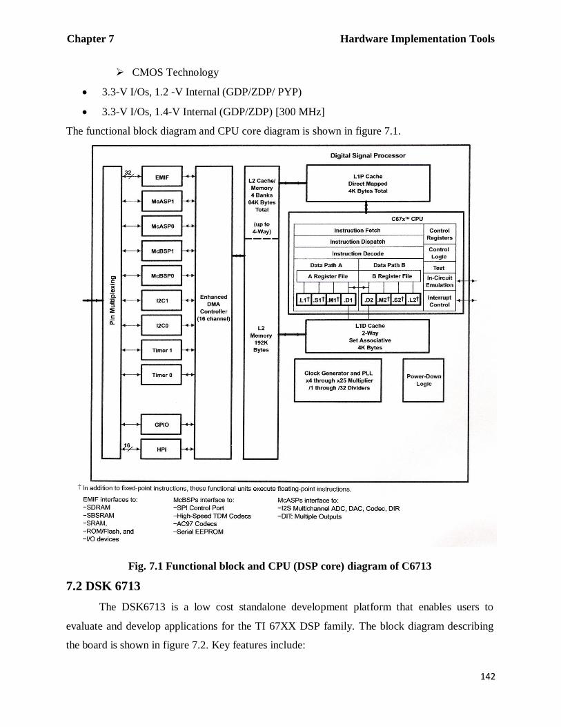
The functional block diagram and CPU core diagram is shown in figure 7.1.
Fig. 7.1 Functional block and CPU (DSP core) diagram of C6713
7.2 DSK 6713
The DSK6713 is a low cost standalone development platform that enables users to
evaluate and develop applications for the TI 67XX DSP family. The block diagram describing
the board is shown in figure 7.2. Key features include:

Chapter 7 Hardware Implementation Tools
143
A TI TMS320C6713 DSP operating at 225 MHz.
An AIC 23 stereo codec.
4 user LEDs and 4 DIP switches.
16 MB SDRAM and 512 KB non-volatile Flash memory.
Software board configuration through registers implemented in CPLD.
JTAG (Joint Test Action Group) emulation through on-board JTAG emulator with USB
host interface or external emulator.
Single voltage power supply (+5V).
Fig. 7.2 DSK 6713 block diagram
7.2.1 Functional Overview of DSK 6713
The DSP on the 6713 DSK interfaces to on-board peripherals through a 32-bit wide
EMIF (External Memory Interface). The SDRAM, Flash and CPLD are all connected to the bus.
All addresses are 32 bits wide. Portions of the internal memory can be reconfigured in software
as L2 cache rather than fixed RAM. The DSP interfaces to analog audio signals through on-
board TLV320AIC23 codec and 3.5mm audio jacks (microphone input, line input, line output
and headphone output). The codec can select the microphone input (monaural input) or the line
input (stereo input) as active input. The analog output is driven to both the line out (fixed gain)
and headphone/speaker out (adjustable gain) connectors. The codec communicates using two

Chapter 7 Hardware Implementation Tools
144
serial channels, one to control the codec‟s internal configuration registers and one to send and
receive digital audio samples. McBSP0 is used to send commands to the codec control interface
while McBSP1 is used for bi-directional digital audio data. The codec has a 12 MHz system
clock. The internal sample rate generate subdivides the 12 MHz clock to generate common
frequencies such as 48 KHz, 44.1 KHz and 8 KHz. The sample rate is set by the codec‟s
SAMPLERATE register. Figure 7.3 shows the codec interface on the C6713 DSK.
A programmable logic device called a CPLD is used to implement glue logic that ties the
board components together. The CPLD has a register based user interface that lets the user
configure the board by reading and writing to its registers. The DSK includes 4 LEDs (D7-D10)
and 4 DIP switches (SW1) as a simple way to provide the user input/output. Both are accessed
by reading and writing to the CPLD registers.
The PC‟s USB port cannot be directly connected to DSP C6713. An XDS (eXtended
Development System) JTAG emulator is connected to the PC‟s USB port and DSP is
communicated through the JTAG emulator on the DSK. CCS uses USB port to control DSP via
JTAG port.
Fig. 7.3 AIC- DSP interface
7.3 Code Composer Studio Integrated Development Environment (CCS IDE)
The Code Composer Studio (CCS) application provides an integrated environment with
the following capabilities [2]:
Integrated development environment (IDE) with an editor, debugger, project

Chapter 7 Hardware Implementation Tools
145
manager, profiler, etc.
„C/C++‟ compiler, assembly optimizer and linker (code generation tools).
Simulator.
Real-time operating system (DSP/BIOS).
Real-Time Data Exchange (RTDX) between the Host and Target.
Real-time analysis and data visualization.
The CCS Project Manager organizes files into folders for source files; include files, libraries and
DSP/BIOS configuration files. Once the files are added to the project any changes in any of
source files will be reflected automatically in the project files. This allows multi user system
development. CCS also provides the ability to debug mixed, multi-processor designs
simultaneously. It also includes new emulation capabilities with Real Time Data Exchange
(RTDX), plus advanced DSP code profiling capabilities. An improved Watch Window monitors
the values of local and global variables and C/C++ expressions. Users can quickly view and
track variables on the target hardware. It has ability to share C and C++ source and libraries in a
multi-user project. The CCS IDE V3.3 is used for implementation here.
Fig. 7.4 Working of code composer studio

Chapter 7 Hardware Implementation Tools
146
7.4 MATLAB/SIMULINK in Real Time Applications
Rapid prototyping is a new approach in digital signal processing systems development.
With the advent of MATLAB's Real Time Workshop (RTW) toolbox it is now possible to
compile, load, and execute graphically designed SIMULINK models on an actual DSP platform,
without spending many workdays coding in typical DSP-oriented languages (assembly
languages), or C/C++ compilers. RTW supports the powerful Texas Instruments 'C6000 series,
including the TMS320C6713 DSP. The basic steps of the complete project development include
designing an algorithm for the given task, implementing a suitable algorithm in MATLAB and
SIMULINK and finally, translating it into target DSP code by means of a rapid prototyping
approach. The original code was developed in MATLAB and so the MATLAB's Real Time
Workshop (RTW) platform is used for rapid prototyping. Real-Time Workshop builds
applications from SIMULINK diagrams for prototyping, testing, and deploying real-time
systems on a variety of target computing platforms, including Texas Instruments C6000 class
DSP processors (Target Support Package TC6).
7.4.1 Real Time Workshop Toolbox
Real Time Workshop is an extension of capabilities of SIMULINK and MATLAB that
automatically generates packages and compiles source code from SIMULINK models to create
real-time software applications on a variety of systems [3]. By providing a code generation
environment for rapid prototyping and deployment, Real-Time Workshop is the foundation for
production code generation capabilities. Along with other tools and components from MATLAB,
Real-Time Workshop provides automatic code generation tailored for a variety of target
platforms, a rapid and direct path from system design to implementation, seamless integration
with MATLAB and SIMULINK, a simple graphical user interface, an open architecture and
extensible make process. The principal components and features of Real-Time Workshop [4] are:
SIMULINK Code Generator: - Automatically generates C code from the SIMULINK
model.
Make Process: - The Real-Time Workshop user-extensible make process lets us
customize compilation and linking of generated code for our own production or rapid
prototyping target.

Chapter 7 Hardware Implementation Tools
147
SIMULINK External Mode: - External mode enables communication between
SIMULINK and a model executing on a real-time test environment, or in another process
on the same machine. External mode lets us to perform real-time parameter tuning, data
logging, and viewing using SIMULINK as a front end.
Targeting Support: - Using the targets bundled with Real-Time Workshop, we can build
systems for real-time and prototyping environments. The generic real-time and other
bundled targets provide a framework for developing customized rapid prototyping or
production target environments.
Rapid Simulations: - Using SIMULINK Accelerator, the S-Function Target, or the Rapid
Simulation Target, we can accelerate our simulations by 5 to 20 times on average.
Executables built with these targets bypass normal SIMULINK interpretive simulation
mode. Code generated by SIMULINK Accelerator, S-Function Target, and Rapid
Simulation Target is highly optimized to execute only the algorithms used in our specific
model. In addition, the code generator applies many optimizations, such as eliminating
ones and zeros in computations for filter blocks.
Large-Scale Modeling: - Support for multilevel modeling (termed "model referencing"),
which lets us to generate code incrementally for a hierarchy of independent component
models, as they evolve.
The Target Language Compiler (TLC) tool is an integral part of the Real-Time
Workshop. It enables customizing the C code generated from any SIMULINK model and
generates optimal, inline code for SIMULINK blocks. Figure 7.5 illustrates how Real-Time
Workshop, helps us in real time system development process and figure 7.6 explains its working.

Chapter 7 Hardware Implementation Tools
148
Fig. 7.5 Role of real time workshop
MATLAB
&
Toolboxes
Customer-defined
monitoring and
parameter tuning,
storage classes
Embedded
Coder
Accelerator, S-
function Target
Rapid Prototyping
Targets (real time)
Embedded
Target
(Custom and
standard)
SIMULINK,
Stateflow
Blocksets
Real Time
Workshop
Rapid Simulation
Target
Embedded
Target (Custom
and standard) Embedded
Target
(Custom and
standard)
Interactive Design Interactive modeling and simulation High-speed simulation
Deployed
system
System testing and tuning
Software integration
Batch design verify
System development
testing
Embedded Target
Software unit
testing
Design
Cycle

Chapter 7 Hardware Implementation Tools
149
Fig. 7.6 Working of real time workshop
7.4.2 Target Support Package TC6
This platform integrates SIMULINK and MATLAB with Texas Instruments eXpressDSP
tools. The software collection allows developing and validating digital signal processing designs
from concept through code. It consists of the TI C6000 target that automates rapid prototyping
on C6000 hardware targets [5]. The target uses C code generated by RTW and CCS to build an
executable file (.out) for the targeted processor. The RTW build process loads the targeted
machine code to target board and runs the executable file on the digital signal processor. All the
features provided by CCS, such as tools for editing, building, debugging, code profiling, and
project management help in developing the applications using MATLAB, SIMULINK, RTW,
and the supported hardware (DSK 6713). Executing code generated from RTW on a particular
target in real time requires that RTW generate target code that is tailored to the specific hardware
target. Target-specific code includes I/O device drivers and an interrupt service routine (ISR).
Since these device drivers and ISRs are specific to particular hardware targets, it must be ensured
that the target-specific components are compatible with the target hardware. To build an
executable, TC6 uses the MATLAB links to invoke the code building process from within CCS.
Once executable file is downloaded to the target and run, the code runs wholly on the target; one

Chapter 7 Hardware Implementation Tools
150
can access the running process only from the CCS debugging tools or across a link for CCS [6]
or Real Time Data Exchange (RTDX). Otherwise the running process is not accessible.
7.5 Summary
The hardware implementation tools viz. DSK 6713, CCS IDE, SIMULINK, MATLAB
RTW and Target Support Package TC6 together can be used to implement any complex speech
processing algorithm on TMS320C6713 DSP platform. The ADC and DAC needed for such
applications are provided on DSK 6713. Also SIMULINK can be used for real time
implementation of speech processing algorithm on PC1. The sound card on PC contains
necessary ADC, DAC and audio power amplifiers. The hybrid algorithm developed here is tested
for real time implementation on PC as well as on DSP. The implementation details are described
in the next chapter.
1 A paper entitled “Simulation and Real Time Implementation of Spectral Subtraction and Wavelet De-Noising
Embedded Algorithms for Speech Enhancement” is published in International Journal of Recent Trends in
Engineering and Technology, (IJRTET), Vol. 4, No. 4, Nov. 2010, pp. 146-149, ACEEE, USA. ISSN
(Online):2158-5563, ISSN (Print): 2158-5555. Archived in SEARCH digital library.