hardware implementation of automatic control systems using ... · hardware implementation of...
TRANSCRIPT

1
Hardware Implementation of Automatic Control Systems using FPGAs
Lecturer PhD Eng. Ionel BOSTAN Lecturer PhD Eng. Florin-Marian BÎRLEANU University of Pitesti Romania
Disclaimer: This presentation tries to show the current trends in the hardware implementation of the PID controller using FPGA circuits and does not contain the authors’ research work.

October 2016 – Perugia, Italy
2
Overview
Hardware Implementation of Automatic Control Systems using FPGAs University of Pitesti
The aims of this group of educational activities are focused on three
directions:
– Presentation of FPGAs as a support for hardware implementation of digital
systems, such as high speed and high performance control systems that can be
useful in renewable energy systems;
– FPGA project implementation – all steps we need in order to design, implement
and test a complete application in FPGA;
– Applications: examples of hardware implementation of PID controllers using
different types of implementation techniques:
– HDL implementation;
– Implementation using System Generator
– Implementation using High Level Synthesis Tools

3
I. Introduction to Automatic Control Systems
I.1. Purpose of ACS;
I.2. Typical structure of ACS;
I.3. PID Controller ;
Software Implementation
Hardware Implementation in FPGA
FPGA Implementation Difficulties

4
Part I. Introduction to Automatic Control Systems
Hardware Implementation of Automatic Control Systems using FPGAs University of Pitesti
I.1. Purpose of Automatic Control Systems (ACS)
Purpose of Automatic Control Systems [1]:
• Power amplification (gain)
- Positioning a large radar antenna by low-power rotation of a knob; - Opening and closing valves;
• Remote control
- Robot arm used to pick up radioactive material; - Unmanned Aerial Vehicles; - Remote Terminal Unit in oil production;
• Convenience of input form
- Changing room temperature by thermostat position; - Quality Control using limit switch;
• Compensation for disturbances
- Controlling antenna position in the presence of large wind disturbance torque; - Control Inventory under variable demand;
October 2016 – Perugia, Italy

5
Part I. Introduction to Automatic Control Systems
Hardware Implementation of Automatic Control Systems using FPGAs University of Pitesti
I.2. Typical Structure of Automatic Control Systems
October 2016 – Perugia, Italy

6
Part I. Introduction to Automatic Control Systems
Hardware Implementation of Automatic Control Systems using FPGAs University of Pitesti
I.2. Typical Structure of Automatic Control Systems
Case Study – Antenna Azimuth Position Control System [1]
October 2016 – Perugia, Italy

7
Part I. Introduction to Automatic Control Systems
Hardware Implementation of Automatic Control Systems using FPGAs University of Pitesti
I.2. Typical Structure of Automatic Control Systems
Case Study – Antenna Azimuth Position Control System [1]
October 2016 – Perugia, Italy

8
Part I. Introduction to Automatic Control Systems
Hardware Implementation of Automatic Control Systems using FPGAs University of Pitesti
I.3. PID Controller
Proportional -Integral - Derivative Controller (PID Controller )
– most used algorithm in industrial control;
– can be software or hardware implemented;
– has tuning difficulties;
Role of each controller term:
– Proportional term – used to drive the controller output according to the size of the error;
– Integral term - used to eliminate the steady-state offset;
– Derivative term – used to evaluate the trend to correct the output and improve the overall
stability by limiting the overshoots;
In many industrial application one control loop is not enough, for example in motor
control:
– Torque is controlled by current loop PID;
– Speed is managed by the velocity PID cascaded with the current PID;
– Position is managed by the space PID cascaded with the velocity PID;
October 2016 – Perugia, Italy

9
Part I. Introduction to Automatic Control Systems
Hardware Implementation of Automatic Control Systems using FPGAs University of Pitesti
I.3. PID Controller – Software Implementation
Complex control systems:
– More PID control loops are needed;
– Sequential execution of each PID loop implemented in software => increased
time delay between input and output;
– In some cases, software implementation of ACS cannot meet the performance
specifications;
– In some cases, microprocessor/microcontroller can be replaced with DSP;
In recent years Network Control Systems are very often used. In these cases many
computational resources need to be allocated for communications purposes, which
can reduce the performance.
October 2016 – Perugia, Italy

10
Part I. Introduction to Automatic Control Systems
Hardware Implementation of Automatic Control Systems using FPGAs University of Pitesti
I.3. PID Controller – Hardware implementation in FPGA
Hardware vs. Software
– First PID controllers were implemented in hardware, using operational amplifiers;
– After microprocessor/microcontroller boom, PID controllers begun to be implemented in software;
– Software implementations => sequential execution => time delay => low performance in cases of
complex systems, with many control loops. Software become unattractive!
FPGA technology has some attractive advantages for hardware implementation of PID
loops:
– FPGA allows multiple instances of PID controllers to operate concurrently, due to massive parallel
resource available on chip ;
– Adding new PID controllers can be done without affecting the performance of existing controllers;
– FPGA are programmable (reconfigurable) and can be updated as easy as any microcontroller;
– In modern circuits such as Xilinx Zynq-7000 All Programmable SoC, additional advantages
appears: Hardware become attractive again!
– Typical advantages of FPGA;
– Typical advantages of ARM Cortex A9 CPU;
– Costs & Power advantage over microcontrollers implementations;
October 2016 – Perugia, Italy
11
Part I. Introduction to Automatic Control Systems
Hardware Implementation of Automatic Control Systems using FPGAs University of Pitesti
I.3. PID Controller – FPGA implementation difficulties
– FPGAs offer great advantage for hardware implementation of the control systems;
– In order to use an FPGA, any controller must be designed and implemented using a
Register Transfer Level (RTL) language such as VHDL or Verilog;
– RTL implementation is difficult for engineers with no background in hardware design;
– In present, using High-Level Synthesis tools and System Generator for DSP, any
control engineer can design any controller by only needing to understand:
– basic resources on an FPGA;
– standard hardware I/O protocols;
– Using HLS tools and System Generator for DSP we can: implement, optimize, analyze
and verify the design on an FPGA;
– Transformation from C/C++ specification to RTL requires no more adaptations than it
was needed from C/C++ to DSP implementation.
Hardware implementation become equal to software implementation !
October 2016 – Perugia, Italy
12
II. FPGA
II.1. FPGA architecture;
II.2. Hardware Description Language (HDL) Design Flow;
II.3. Hardware implementation using System Generator;
II.4. Hardware implementation using High Level Synthesis tools (Vivado)
II.5. Design Verification

13
Part II. FPGA
Hardware Implementation of Automatic Control Systems using FPGAs University of Pitesti
Why FPGA?
In present a great number of numerical systems are implemented with FPGA circuits due to their advantages over the general purpose logic IC:
– completely reconfigurable – different projects can be implemented on the same
circuit at different times;
– low cost due to the mass production;
– easy to use – mature high level design tools are available;
– an immense number of digital circuits which are connected by the end user;
– can be used for high speed systems due to their parallel architecture;
For any future specialist in electronics it is very important to be able to
use these circuits in different designs.
October 2016 – Perugia, Italy

14
Part II. FPGA
Hardware Implementation of Automatic Control Systems using FPGAs University of Pitesti
II.1. FPGA Architecture
Typical Architecture FPGA advantage over a microprocessor
October 2016 – Perugia, Italy

15
Part II. FPGA
Hardware Implementation of Automatic Control Systems using FPGAs University of Pitesti
II.1. FPGA Architecture
Software microprocessor from Xilinx [2]
October 2016 – Perugia, Italy

16
Part II. FPGA
Hardware Implementation of Automatic Control Systems using FPGAs University of Pitesti
II.1. FPGA Architecture
System FPGA
October 2016 – Perugia, Italy

17
Part II. FPGA
Hardware Implementation of Automatic Control Systems using FPGAs University of Pitesti
II.1. FPGA Architecture
System on Chip
(SoC)
[3]
October 2016 – Perugia, Italy

18
Part II. FPGA
Hardware Implementation of Automatic Control Systems using FPGAs University of Pitesti
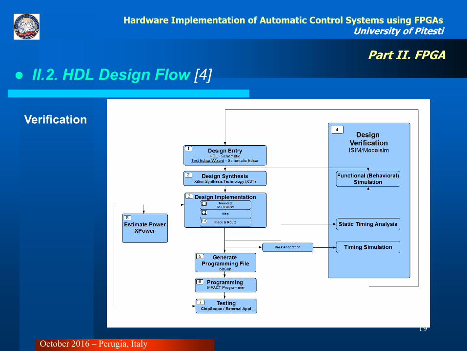
II.2. HDL Design Flow [4]
Hardware
Description
Language
(HDL)
Example:
- VHDL;
- Verilog;
October 2016 – Perugia, Italy
19
Part II. FPGA
Hardware Implementation of Automatic Control Systems using FPGAs University of Pitesti
II.2. HDL Design Flow [4]
Verification
October 2016 – Perugia, Italy

20
Part II. FPGA
Hardware Implementation of Automatic Control Systems using FPGAs University of Pitesti
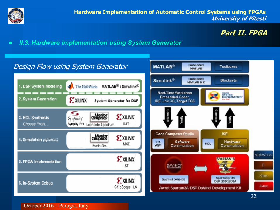
II.3. Hardware implementation using System Generator
System Generator (SysGen) is [5], [6]:
– a system-level modeling tool that facilitates hardware design on FPGA;
– it extends Simulink in many ways to provide a modeling environment that is well suited to hardware design;
– the tool provides high-level abstractions that are automatically compiled into an FPGA
at the push of a button;
– System Generator does not replace hardware description language (HDL)-based
design, but does makes it possible to focus your attention only on the critical parts;
– Critical parts of the design can be made in HDL and less critical parts can be made
using SysGen, and then the HDL and SysGen parts can be connected;
By analogy, most DSP programmers do not program exclusively in assembler; they
start in a higher level language like C, and write assembly code only where it is
required in order to meet performance requirements.
October 2016 – Perugia, Italy

21
Part II. FPGA
Hardware Implementation of Automatic Control Systems using FPGAs University of Pitesti
II.3. Hardware implementation using System Generator
Where to use System Generator (SysGen) [5], [6]:
• Algorithm Exploration: System Generator is particularly useful for algorithm exploration, design
prototyping, and model analysis. When these are the goals, you can use the tool to flesh out an
algorithm in order to get a feel for the design problems that are likely to be faced, and perhaps to
estimate the cost and performance of an implementation in hardware. The work is preparatory, and
there is little need to translate the design into hardware. Simulink blocks and MATLAB M-code
provide stimuli for simulations, and for analyzing results. Resource estimation gives a rough idea of
the cost of the design in hardware.
• Implement a Part of a Large Design: Often System Generator is used to implement a portion of a larger
design. For example, System Generator is a good setting in which to implement data paths and control, but is less well suited for sophisticated external interfaces that have strict timing requirements. In this case, it may be useful to implement parts of the design using System Generator, implement other parts outside, and then combine the parts into a working whole. A typical approach to this flow is to create an HDL wrapper that represents the entire design, and to use the System Generator portion as a component. The non-System Generator portions of the design can also be components in the wrapper, or can be instantiated directly in the wrapper.
• Implement a Complete Design: Many times, everything needed for a design is available inside
System Generator. For such a design, pressing the Generate button instructs System Generator to translate the design into HDL, and to write the files needed to process the HDL using downstream tools.
October 2016 – Perugia, Italy
22
Part II. FPGA
Hardware Implementation of Automatic Control Systems using FPGAs University of Pitesti
II.3. Hardware implementation using System Generator
Design Flow using System Generator
October 2016 – Perugia, Italy
23
Part II. FPGA
Hardware Implementation of Automatic Control Systems using FPGAs University of Pitesti
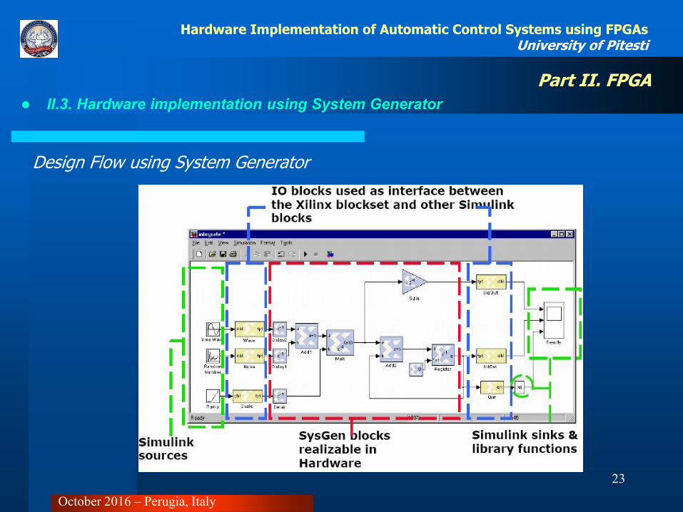
II.3. Hardware implementation using System Generator
Design Flow using System Generator
October 2016 – Perugia, Italy

24
Part II. FPGA
Hardware Implementation of Automatic Control Systems using FPGAs University of Pitesti
II.4. Hardware implementation using HLS
Design Flow [7], [8]
• Inputs: C/C++ based input design
specification, constrains and directives;
• Outputs: RTL design files in VHDL,
Verilog, SystemC;
• In addition to that, verification and
implementation scripts, used to
automated the RTL verification and RTL
synthesis steps, are also created.
October 2016 – Perugia, Italy
25
Part II. FPGA
Hardware Implementation of Automatic Control Systems using FPGAs University of Pitesti
II.4. Hardware implementation using HLS
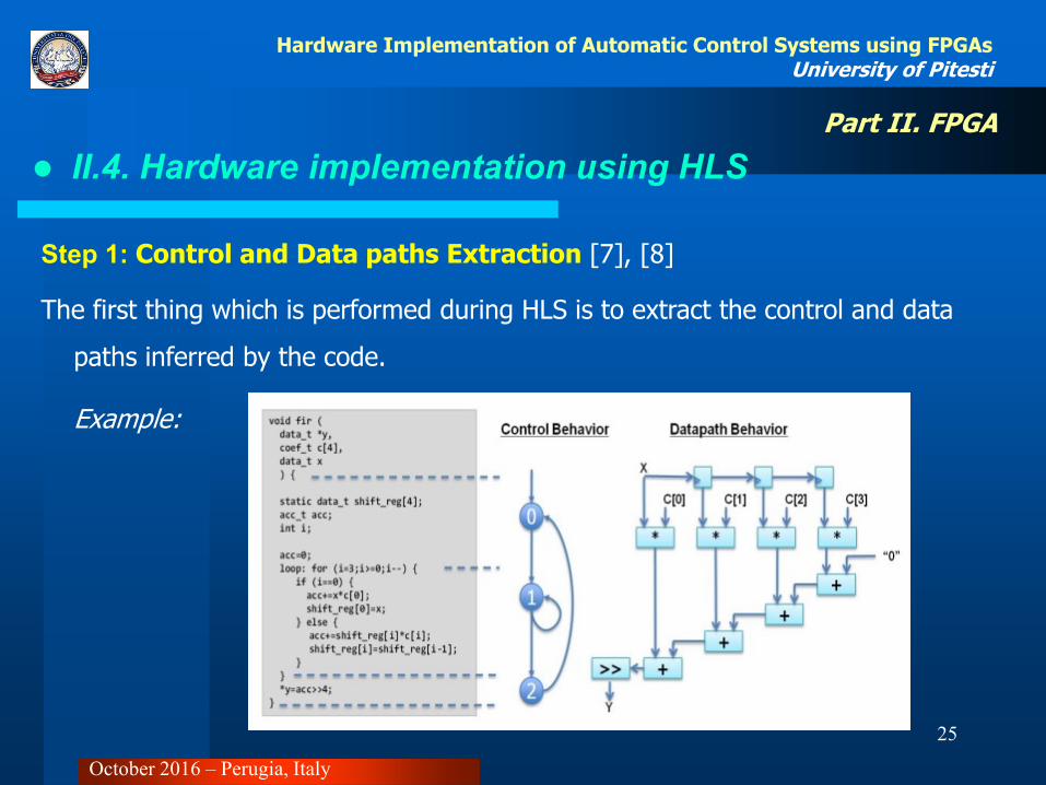
Step 1: Control and Data paths Extraction [7], [8]
The first thing which is performed during HLS is to extract the control and data
paths inferred by the code.
Example:
October 2016 – Perugia, Italy

26
Part II. FPGA
Hardware Implementation of Automatic Control Systems using FPGAs University of Pitesti
II.4. Hardware implementation using HLS
Step 2: Scheduling & Binding [7],
[8]
For the same example code shown in the previous slide, multiple RTL implementations are possible.
1. Using 4 clock cycles means a single adder and
multiplier can be used, as High-Level Synthesis can share the adder and multiplier across clock cycles: 1 adder, 1 multiplier and 4 clock cycles to complete.
2. If analysis of the target technology timing indicates the adder chain can complete in 1 clock cycle, a design which uses 3 adders and 4 multipliers but which finish in 1 clock cycle can be realized (faster but larger than option 1).
3. Take 2 clock cycles to finish but use only 2 adders and 2 multipliers (smaller than option
2 but faster than option 1). October 2016 – Perugia, Italy

27
Part II. FPGA
Hardware Implementation of Automatic Control Systems using FPGAs University of Pitesti
II.4. Hardware implementation using HLS
Step 3: Optimization [7], [8]
High-Level Synthesis can perform a number
of optimizations on the design to produce
high quality RTL satisfying the
performance and area goals.
Pipelining is an optimization which allows one
of the major performance advantages of
hardware over software, concurrent or
parallel operation, to be automatically
implemented in the RTL design.
October 2016 – Perugia, Italy

28
Part II. FPGA
Hardware Implementation of Automatic Control Systems using FPGAs University of Pitesti
II.4. Hardware implementation using HLS [hls1]
Step 4: Constrains [7], [8]
Finally, in addition to the clock period and clock uncertainty, High-Level Synthesis offers a
number of design constraints including the ability to:
• Specify a specific latency across functions, loops and regions.
• Specify a limit on the number of resources used.
• Override the inherent or implied dependencies in the code and permit
operations (for example, a memory read before write)
These constraints can be applied using High-Level Synthesis directives to create a design
with the desired attributes.
October 2016 – Perugia, Italy

29
Part II. FPGA
Hardware Implementation of Automatic Control Systems using FPGAs University of Pitesti
II.5. Design Verification
Best Practice [9]
1. Use modeling and simulation to optimize at the system level.
2. Automatically generate readable, traceable HDL code for FPGA prototyping.
3. Reuse system-level test benches with cosimulation for HDL verification.
4. Enable regression testing with FPGA-in-the-loop simulation.
October 2016 – Perugia, Italy

30
Part II. FPGA
Hardware Implementation of Automatic Control Systems using FPGAs University of Pitesti
II.5. Design Verification
Cosimulation [10]
October 2016 – Perugia, Italy
31
Part II. FPGA
Hardware Implementation of Automatic Control Systems using FPGAs University of Pitesti
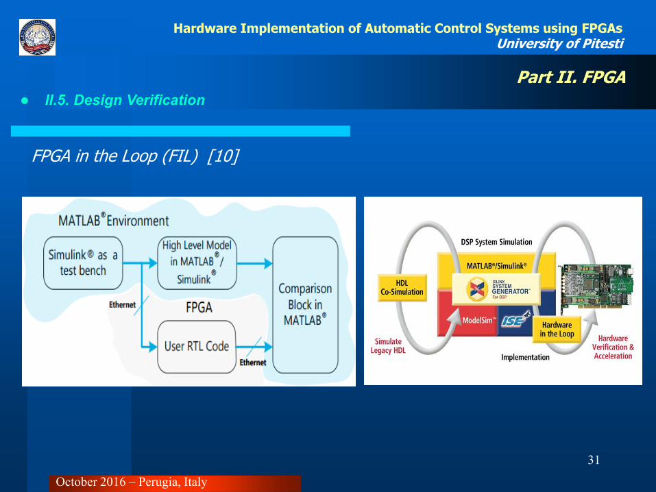
II.5. Design Verification
FPGA in the Loop (FIL) [10]
October 2016 – Perugia, Italy

32
Part II. FPGA
Hardware Implementation of Automatic Control Systems using FPGAs University of Pitesti
II.5. Design Verification – FIL
FPGA-in-the-loop (FIL) enables you to run a Simulink or MATLAB simulation that is synchronized with an HDL design running on an Altera® or Xilinx® FPGA board. This link between the simulator and the board enables you to:
• Verify HDL implementations directly against algorithms in Simulink or MATLAB.
• Apply data and test scenarios from Simulink or MATLAB to the HDL design on the FPGA.
• Integrate existing HDL code with models under development in Simulink or MATLAB.
October 2016 – Perugia, Italy

33
Part II. FPGA
Hardware Implementation of Automatic Control Systems using FPGAs University of Pitesti
II.5. Design Verification – FIL
Requirements: [11]
– MATLAB, Simulink, Fixed-Point Designer, HDL Verifier;
– FPGA design software (Xilinx® ISE® design suite, or Xilinx® Vivado® design suite, or Altera® Quartus® II design software);
– One of the supported FPGA development boards and accessories
Steps to follow: [11]
Step 1: Set Up FPGA Development Board
Step 2: Set Up Host Computer-Board Connection
Step 3: Prepare Example Resources
Step 4: Launch FPGA-in-the-Loop (FIL) Wizard
Step 5: Specify Hardware Options in FIL Wizard
October 2016 – Perugia, Italy

34
Part II. FPGA
Hardware Implementation of Automatic Control Systems using FPGAs University of Pitesti
II.5. Design Verification – FIL
Steps to follow (continued): [11]
Step 6: Specify HDL Files in the FIL Wizard
Step 7: Review I/O Ports in FIL Wizard
Step 8: Set Output Data Types in FIL Wizard
Step 9: Review Build Options in FIL Wizard
Step 10: Set Up Model
Step 11: Program FPGA
Step 12: Review Parameters of FIL Block
Step 13: Run FIL
October 2016 – Perugia, Italy
35
III. Examples of PID controllers implemented in FPGA
Example 1: RTL synthesis of a PID controller
Example 2: HLS of a PID controller
Example 3: HLS of a fuzzy PID controller

36
Part III. Examples of PID controllers implemented in FPGA
Hardware Implementation of Automatic Control Systems using FPGAs University of Pitesti
Ex. 1: RTL Synthesis of a PID Controller
PID Equations (time/Laplace) [12]
October 2016 – Perugia, Italy

37
Part III. Examples of PID controllers implemented in FPGA
Hardware Implementation of Automatic Control Systems using FPGAs University of Pitesti
Ex. 1: RTL Synthesis of an PID controller
PID Equations (Discrete Time) [12]
October 2016 – Perugia, Italy

38
Part III. Examples of PID controllers implemented in FPGA
Hardware Implementation of Automatic Control Systems using FPGAs University of Pitesti
Ex. 1: RTL Synthesis of a PID Controller
PID Algorithm implementation in C [12]
October 2016 – Perugia, Italy
39
Part III. Examples of PID controllers implemented in FPGA
Hardware Implementation of Automatic Control Systems using FPGAs University of Pitesti
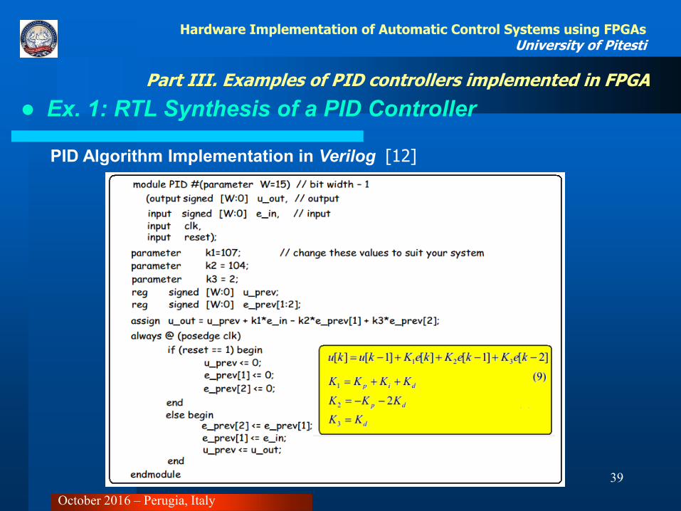
Ex. 1: RTL Synthesis of a PID Controller
PID Algorithm Implementation in Verilog [12]
October 2016 – Perugia, Italy

40
Part III. Examples of PID controllers implemented in FPGA
Hardware Implementation of Automatic Control Systems using FPGAs University of Pitesti
Ex. 2: HLS of a PID Controller
Closed Loop Control System [13]
October 2016 – Perugia, Italy

41
Part III. Examples of PID controllers implemented in FPGA
Hardware Implementation of Automatic Control Systems using FPGAs University of Pitesti
Ex. 2: HLS of a PID Controller [13]
October 2016 – Perugia, Italy
42
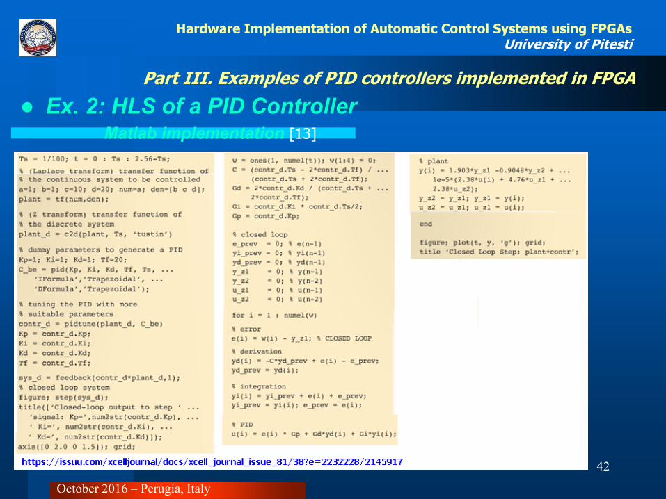
Part III. Examples of PID controllers implemented in FPGA
Hardware Implementation of Automatic Control Systems using FPGAs University of Pitesti
Ex. 2: HLS of a PID Controller Matlab implementation [13]
October 2016 – Perugia, Italy

43
Part III. Examples of PID controllers implemented in FPGA
Hardware Implementation of Automatic Control Systems using FPGAs University of Pitesti
Ex. 2: HLS of a PID Controller
C implementation [13]
October 2016 – Perugia, Italy

44
Part III. Examples of PID controllers implemented in FPGA
Hardware Implementation of Automatic Control Systems using FPGAs University of Pitesti
Ex. 2: HLS of a PID Controller
VHDL code generation using HLS Vivado [13]
October 2016 – Perugia, Italy

45
Part III. Examples of PID controllers implemented in FPGA
Hardware Implementation of Automatic Control Systems using FPGAs University of Pitesti
Ex. 3: High Level Synthesis of a Fuzzy PID Controller
[14]
October 2016 – Perugia, Italy

46
Part III. Examples of PID controllers implemented in FPGA
Hardware Implementation of Automatic Control Systems using FPGAs University of Pitesti
Ex. 3: High Level Synthesis of a Fuzzy PID Controller
[14]
October 2016 – Perugia, Italy
47
Part III. Examples of PID controllers implemented in FPGA
Hardware Implementation of Automatic Control Systems using FPGAs University of Pitesti
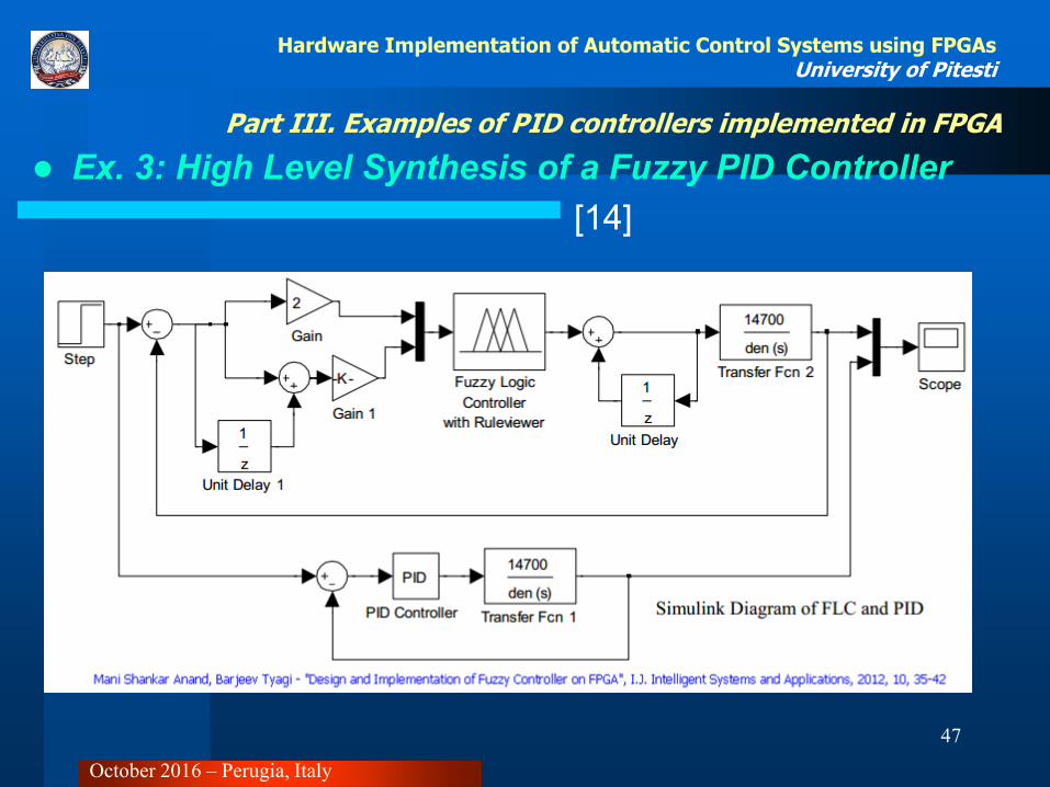
Ex. 3: High Level Synthesis of a Fuzzy PID Controller
[14]
October 2016 – Perugia, Italy
48
Part III. Examples of PID controllers implemented in FPGA
Hardware Implementation of Automatic Control Systems using FPGAs University of Pitesti
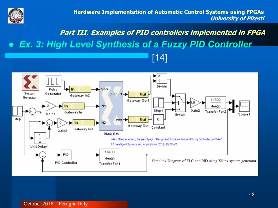
Ex. 3: High Level Synthesis of a Fuzzy PID Controller
[14]
October 2016 – Perugia, Italy

49
Part III. Examples of PID controllers implemented in FPGA
Hardware Implementation of Automatic Control Systems using FPGAs University of Pitesti
Ex. 3: High Level Synthesis of a Fuzzy PID Controller
[14]
October 2016 – Perugia, Italy
50
Hardware Implementation of Automatic Control Systems using FPGAs University of Pitesti
[1] Fouad M. AL-Sunni , “Introduction_To_Control_Systems”,
https://opencourseware.kfupm.edu.sa/colleges/ccse/se/se302/files%5C1._Introduction_To_Control_Systems_SE302_Topic_1_-_Introduction_to_Linear_systems.pdf
[2] http://www.xilinx.com/products/design-tools/microblaze.html
[3] http://www.xilinx.com/products/silicon-devices/soc.html
[4] https://www.so-logic.net/documents/knowledge/tutorial/Basic_FPGA_Tutorial_ISE/Basic_FPGA_Tutorial2.html#toc0
[5] http://www.xilinx.com/products/design-tools/vivado/integration/sysgen.html
[6] http://www.xilinx.com/support/documentation/sw_manuals/xilinx14_4/sysgen_user.pdf
[7] http://files.meetup.com/3753142/VHLS_NY_Final_Distributed.pdf
[8] Vivado Design Suite User Guide, http://www.xilinx.com/support/documentation/sw_manuals/xilinx2012_4/ug902-vivado-high-level-synthesis.pdf
[9] http://www.eejournal.com/archives/articles/20110825-mathworks/
[10] Paweł Ządek, Arkadiusz Koczor, Michał Gołek, Łukasz Matoga, Piotr Penkala, “Improving Efficiency of FPGA-in-the-Loop Verification Environment”, IFAC-PapersOnLine 48-4 (2015) 180–185
[11] Verify HDL Implementation of PID Controller Using FPGA-in-the-Loop. http://www.mathworks.com/help/hdlverifier/examples/verify-hdl-implementation-of-pid-controller-using-fpga-in-the-loop.html
[12] Varodom Toochinda, Digital PID Controllers, http://controlsystemslab.com/category/articles/control-engineering/pid/
[13] https://issuu.com/xcelljournal/docs/xcell_journal_issue_81/38?e=2232228/2145917
[14] Mani Shankar Anand, Barjeev Tyagi, Design and Implementation of Fuzzy Controller on FPGA, I.J. Intelligent Systems and Applications, 2012, 10, 35-42
References
October 2016 – Perugia, Italy

51
Hardware Implementation of Automatic Control Systems using FPGAs University of Pitesti
Thank you for your attention!
October 2016 – Perugia, Italy