handout for training-turbine
TRANSCRIPT

Technical Data Steam Turbine Construction, Speed,Descri pti on Steam Pressures
Construction
Three-cylinder reheat condensing turbine EMAR Single-flow HP turbine with 25 reaction stages Type H30-25-2
.. _
Double-flow IP turbine with 20 reaction stages per flow Type M30-20
Double-flow LP turbine with 8 reaction stages per flow Type N30-2x5
2 mai n stop and control valves Type EV160
2 reheat stop and control valves Type IV320
2 swing check valves in cold reheat line DN450·
2 bypass stop and control valves DN200
Extraction Swing Check Valves:
Extraction 1: no valve.
Extraction 2: 1 swing check valve with auxiliary actuator, 1 swing check valve,
Extraction 3: 1 swing check valve with auxiliary actuator, 1 swing check valve,
Extraction 4: 1 swing check valve with auxiliary actuator, 1 swing check valve,
Extraction 5: 1 swing check valve with auxiliary actuator, 1 swing check valve,
Extraction 6: no valve
Speed
Rated speed 50,0 S-1
Speed limitation in load and station auxiliary load operation
Max. speed, no time limitation: 51,5 $"1
Min. speed no time limitation: 47,5 $"1
Permissible for a maximum of 2 hours during the life of Ip blading speeds below 47,5 S-l
speeds above 51 ,5 S-1
Speed exclusion range at operation without load * 11,67 s-J to 47,5 S-I
Standard overspeed trip setting max. 55,5 S-I
• This speed range should be passed through in one smooth operation to avoid endangering the blades due to resonance.
Direction of Rotation Anti Clockwise when viewed from Front Pedestal towards the Generator.
~MA
-
I Steam Pressures
Rated· . Long-time
operation Short-time
operation
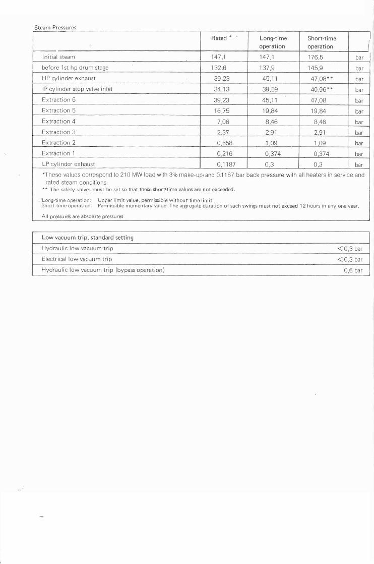
Initial steam 147,1 147,1 176,5 bar
before 1st hp drum stage 132,6 137,9 145,9 bar
HP cylinder exhaust 39,23 45,11 47,08** bar
IP cylinder stop valve inlet 34,13 39,59 40,96** bar
Extraction 6 39,23 45,11 47,08 bar
Extraction 5 16,75 19,84 19,84 bar
Extraction 4 7,06 8,46 8,46 bar
Extraction 3 2,37 2,91 2,91 bar
Extraction 2 0,858 .1,09 1,09 bar
Extraction 1 0,216 0,374 0,374 bar
LP cylinder exhaust 0,1187 0,3 0,3 bar
'These values correspond to 210 MW load with 3% make-up, and 0.1187 bar back pressure with all heaters in service and rated steam conditions.
** The safety valves must be set so that these short'time values are not exceeded.
. Long-time operation: Upper limit value, permissible without time limit Short-time operation: Permissible momentary value. The aggregate duration of such swings must not exceed 12 hours in anyone year.
All pressure's are absolute pressures
Low vacuum trip, standard setting
Hydraulic low vacuum trip <0,3 bar
Electrical low vacuum trip < 0,3 bar
Hydraulic low vacuum trip (bypass operation) 0,6 bar
--
l
Technical Data Steam Turbine Steam and Casing Temperatures Description Feedwater Heaters Out of Service
Steam Temperatures
Rated value
Annual mean
value
Long-time value
but keeping within
annual mean value
400 h per annum 80 h per annum
max. 15. min. in
individual cases
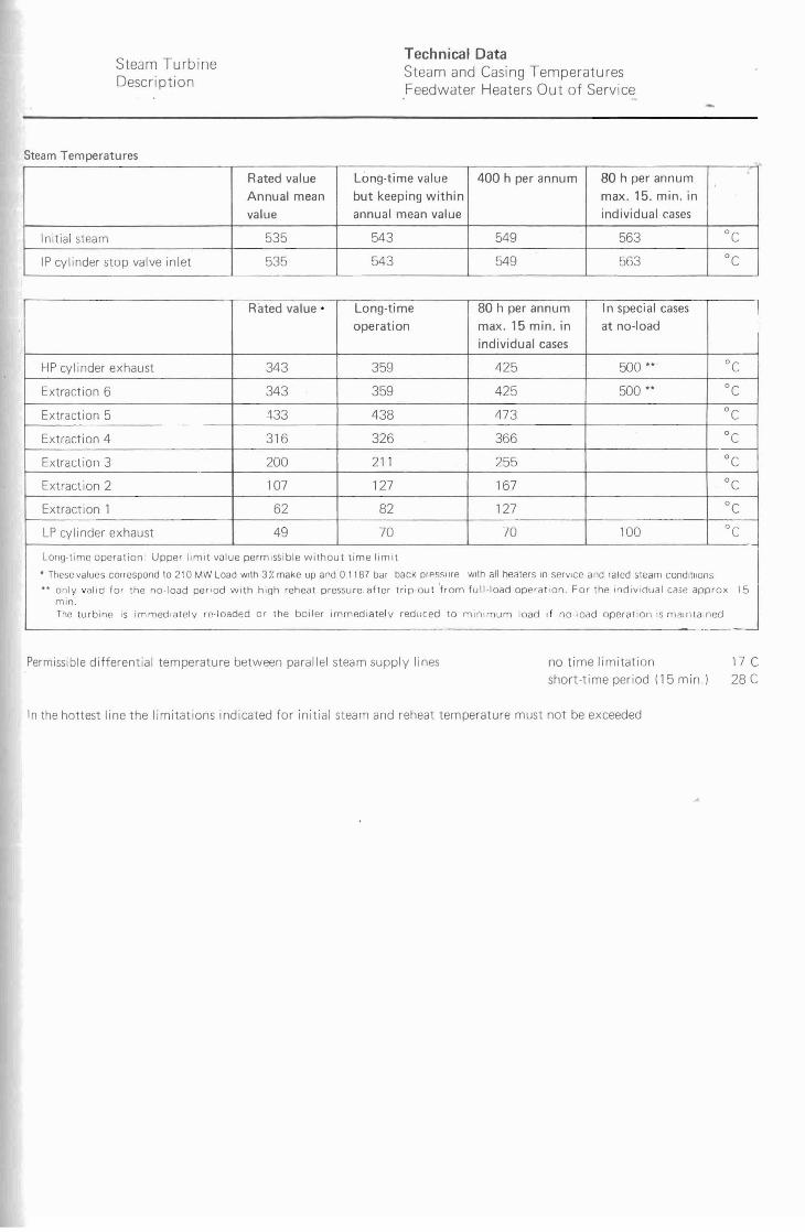
Initial steam 535 543 549 563 °c IP cylinder stop valve inlet 535 543 549 563 °c
EMA
80 h per annum In speci al casesLong-timeRated value· \
max. 15 min. in at no-load
individual cases
HP cylinder exhaust
operation
500 ••359 425343 °c 500 ••343 425Extraction 6 359 °c
473Extraction 5 433 438 °c 316 326 366Extraction 4 °c
211Extraction 3 255200 °c 127 167Extraction 2 107 °c
Extract ion 1 62 82 127 °c "c49 70 70 100LP cylinder exhaust
Long-time operation: Upper limit value permissible without lime limit
• These values correspond to 210 MW Load with 3Z make up and 0.1187 bar back or"sslire wllh all heaters In service and rated steam condltllons 'J.. '0" ""d '" ", ",'''d '''',d .,," """ ,,",", '"'''''' '''eo ",,""'h,m ''''''ood "''''''0 F", ", 'od"""" "" ""'" min. The turbine IS immediately re-Ioaded or the boiler immediately reduced to minimum load if no·load operation :s maintained
Permissible differential temperature between parallel steam supply lines no time limitation 17 C short-time period (15 min.) 28 C
In the hottest line the limitations indicated for initial steam and reheat temperature must not be exceeded
..
~MA
-
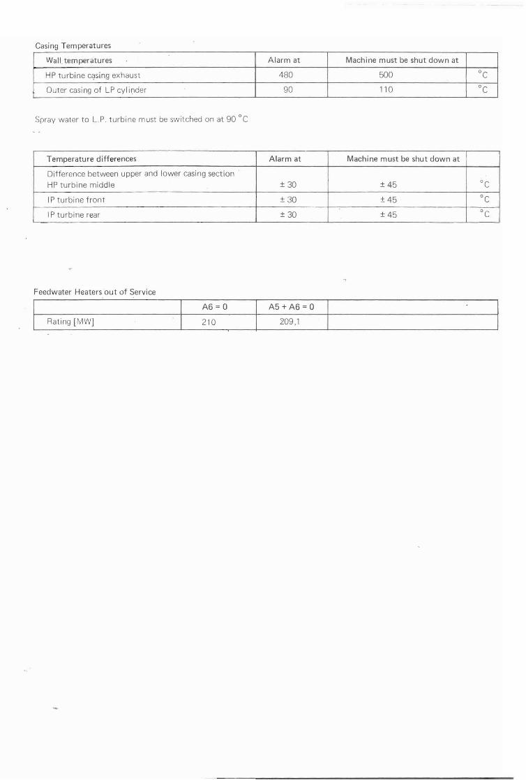
Casing Temperatures
Wall. temperatures Alarm at Machine must be shut down at
HP turbine c9sing exhaust 480 500 DC
Outer casing of LP cylinder 90 110 DC
Spray water to L.P. turbine must be switched on at 90 DC
Temperature differences Alarm at Machine must be shut down at
Difference between upper and lower casing section
HP turbine middle ± 30 ± 45 DC
IP turbi ne front ± 30 ± 45 DC
IP turbine rear ± 30 ± 45 DC
Feedwater Heaters ·out of Service
A6= 0 A5 + A6 = 0
Rating [MW] 210 209,1
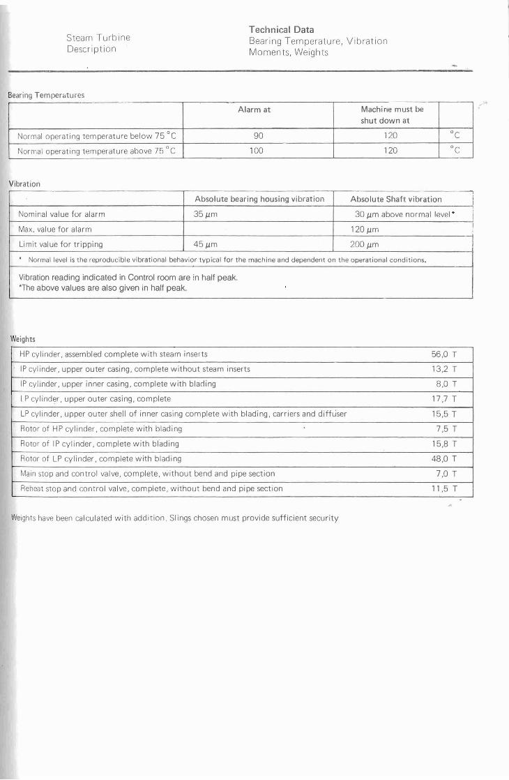
Technical Data Steam Turbine Bearing Temperature, Vibration Description Moments, Weights
Bearing Temperatures
Alarm at Machine must be
shut down at
Normal operating temperature below 75°C 90 120 °c
Normal operating temperature above 75°C 100 120 °c
EMARI
Vibration
Absolute bearing housing vibration Absolute Shaft vibration
INominal value for alarm 35 pm 30 pm above normal level *
Max. value for alarm 120 pm ! Limit value for tripping 45 pm 200 pm . Normal level is the reproducible vibrational behavior typical for the machine and dependent on the operational conditions.
Vibration reading indicated in Control room are in half peak. -The above values are also given in half peak. .
Weights
HP cylinder, assembled complete with steam inserts 56,0 T
IP cylinder. upper outer casing, complete without steam inserts 13.2 T
IP cylinder, upper inner casing, complete with blading 8,0 T
LP cylinder, upper outer casing, complete 17.7 T
LP cylinder, upper outer shell of inner casing complete with blading, carriers and diffuser 15,5 T
Rotor of HP cylinder, complete with blading 7,5 T
Rotor of IP cylinder, complete with blading 15,8 T
Rotor of LP cylinder, complete with blading 48,0 T
Main stop and control valve, complete, without bend and pipe section 7,0 T
Reheat stop and control valve, complete, without bend and pipe section 11,5 T
Weights have been calculated with addition. Slings chosen must provide sufficient security
-
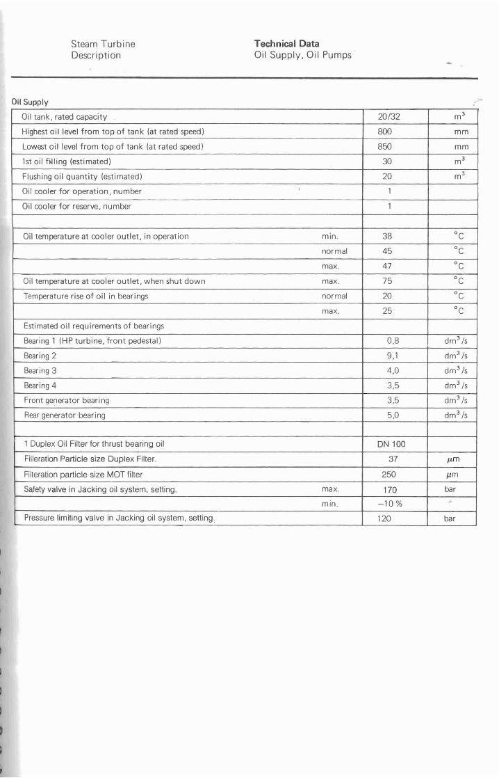
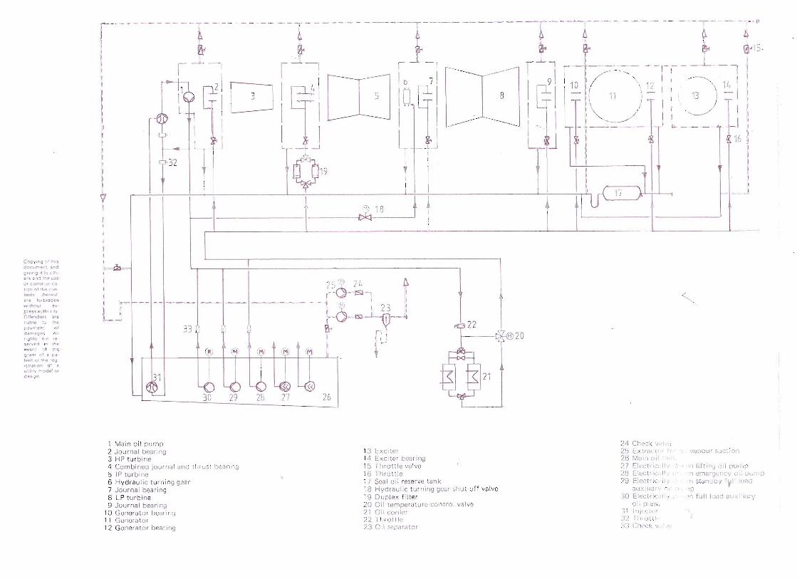
Steam Turbine Technical Data Description Oil Supply, Oil Pumps
Oil Supply
Oil tank, rated capacity 20/32 m3
Highest oil level from top of tank (at rated speed) 800 mm
Lowest oil level from top of tank (at rated speed) 850 mm
1st oil fiJling (estimated) 30 m3
Flushing oil quantity (estimated) 20 m J
Oil cooler for operation, number 1
Oil cooler for reserve, number 1
Oil temperature at cooler outlet, in operation min. 38 °c normal 45 °c max. 47 °c
Oil temperature at cooler outlet, when shut down max. 75 °c Temperature rise of oil in bearings normal 20 °c
max. 25 °c Estimated oil requirements of bearings
Bearing 1 (HP turbine,'front pedestal) 0,8 dm J /s
Bearing 2 9,1 dm 3 /s
Bearing 3 4,0 dm3 /s
Bearing 4 3,5 dm3 /s
Front generator bearing 3,5 dm3 /s
Rear generator bearing 5,0 dm3 /s
1 Duplex Oil Filter for thrust bearing oil DN 100
Filleration Particle size Duplex Filter. 37 /-Lm
Filteration particle size MOT filter 250 IJ.m
Safety valve in Jacking oil system, setting. max. 170 bar
min. -10% .. Pressure limiting valve in Jacking oil system. setting 120 bar
EMAI
-

Jacking oil Pump, speeds when switchng on and off Jacking oil pump must be switched on at turbine speeds below approx. 8,5 s-J to avoid damage to bearing. Jacking oil pump should be switched off at. speeds above approx. 9,0 s-J .
Oil Pumps
. Main Oil pump Auxiliary oil pump
DC Emergency. oil pump
Jacking oil pump
Quantity 1 2 1 2 . Ma~er BHEL KSB KSB Allweiler
Type . ETA150-50VL ETA 100-33V L SDF40-R54
Capacity (rated l 139 78,31 30 1,26 dm 3 /s
Discharge pressure (gaugel. 8,2 6,8 . 2,3 120 bar
Speed 50 24,66 24,3 49,16 s-J
o Steam Turbine HP-Turbine Description Casing
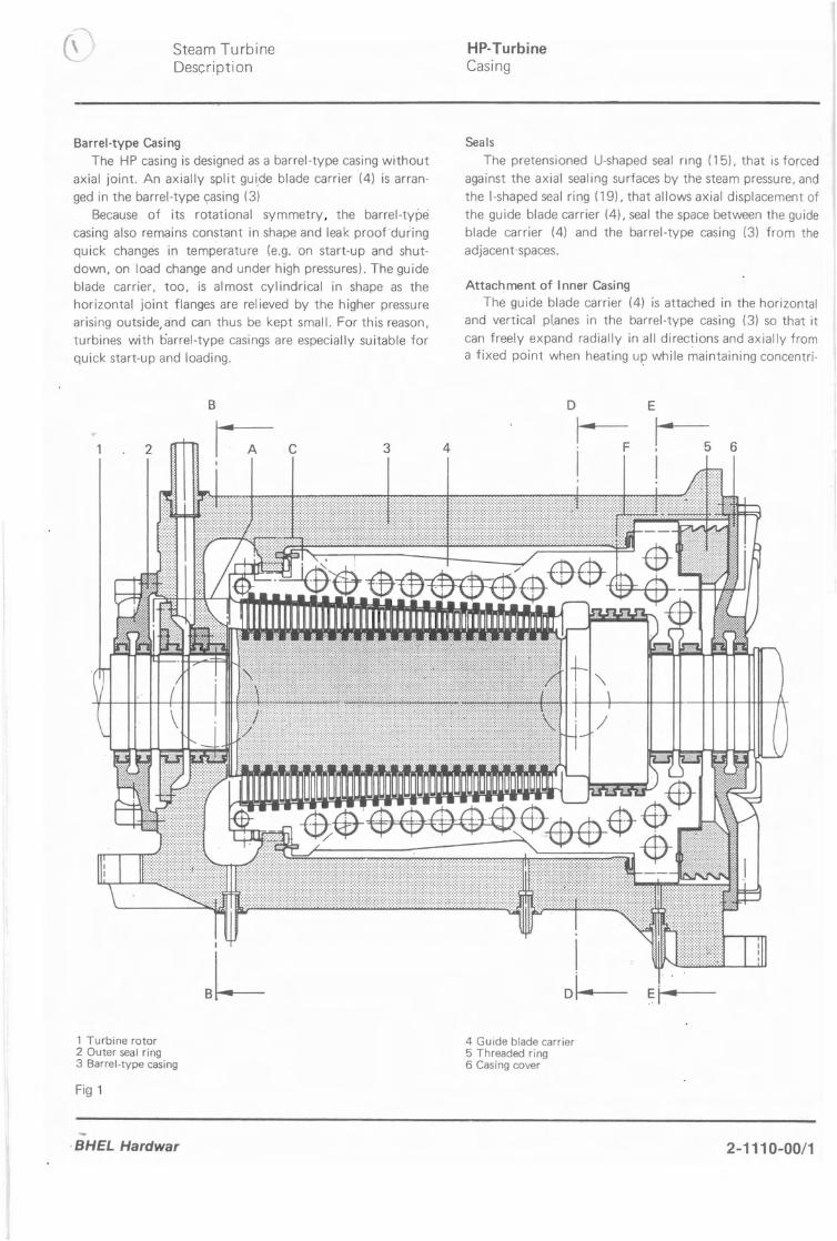
Barrel-type Casing The HP casing is designed as a barrel-type casing without
axial joint. An axially split guide blade carrier (4) is arranged in the barrel-type yasing (3)
Because of its rotational symmetry, the barrel-type casing also remains constant in shape and leak proofduring quick changes in temperature (e.g. on start-up and shutdown, on load change and under high pressures). The guide blade carrier, too, is almost cylindrical in shape as the horizontal joint flanges are relieved by the higher pressure arising outside, and can thus be kept small. For this reason, turbines with barrel-type casings are especially suitable for quick start-up and loading.
B
2 C 3 4
I
aL
Seals The pretensioned U-shaped seal nng (15), that is forced
against the axial sealing surfaces by the steam pressure, and the I-shaped seal ring (19), that allows axial displacement of the guide blade carrier (4), seal the space between the guide blade carrier (4) and the barrel-type casing (3) from the adjacent spaces.
Attachment of Inner Casing The guide blade carrier (4) is attached in the horizontal
and vertical pl.anes in the barrel-type casing (3) so that it
can freely expand radially in all directions and axially from a fixed point when heating up while maintaining concentri·
D
6
Ei
1 Turbine rotor 4 Guide blade carrier 2 Outer seal ring 5 Threaded ring 3 Barrel-type casing 6 Casing cover
Fig 1
BHEL Hardwar 2-1110-00/1
I Section 0-0
3 4 7 8 9 JO
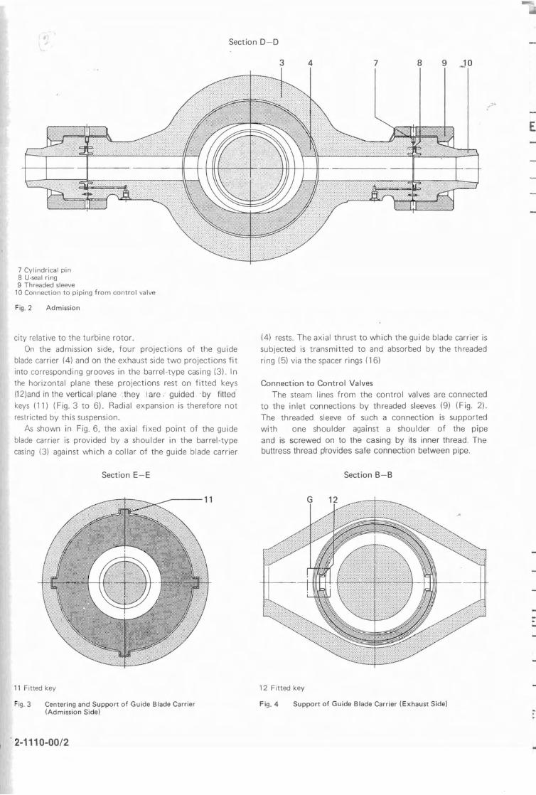
7 Cylindrical pin 8 U-seal ring 9 Threaded sleeve
10 Connection to piping from control valve
Fig. 2 Admission
city relative to the turbine rotor. On the admission side, four projections of the guide
blade carrier (4) and on the exhaust side two projections fit into corresponding grooves in the barrel-type casing (3). In the horizontal plane these projections rest on fitted keys 112)and in the vertical' plane :they Iare. gUided .by fitted' keys (11) (Fig. 3 to 6). Radial expansion is therefore not restricted by this suspension.
As shown in Fig. 6, the axial fixed point of the guide blade carrier is provided by a shoulder in the barrel-type casing (3) against which a collar of the guide blade carrier
Section E-E
EMA
(4) rests. The axial thrust to which the guide blade carrier is subjected is transmitted to and absorbed by the threaded ring (5) via the spacer rings (16)
Connection to Control Valves The steam lines from the control valves are connected
to the inlet connections by threaded sleeves (9) (Fig. 2). The threaded sleeve of such a connection is supported with one shoulder against a shoulder of the pipe and is screwed on to the casing by its inner thread. The buttress thread provides safe connection between pipe.
Section B-B
11 Fitted key 12 Fitted key
Fig. 3 Centering and Support of Guide Blade Carrier Fig.4 Support of Guide Blade Carrier (Exhaust Side) (Admission Side)
2-1110-00/2 -
Detail G Section H-H Section L-L
--jH
~-7Il~-+-12
-++-+--13
~F+-+--14
--1H
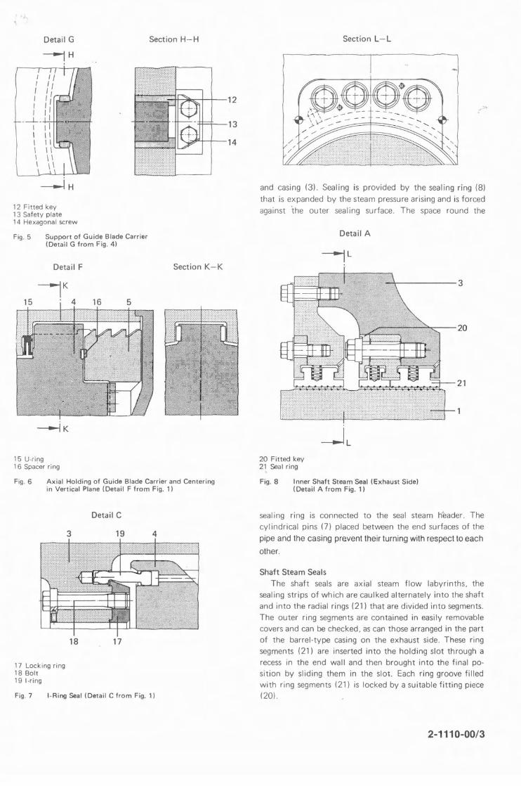
12 Fitted key 13 Safety plate 14 Hexagonal screw
Fig. 5 Support of Guide Blade Carrier (Detail G from Fig. 4)
Detail F Section K-K
15 U-ring 16 Spacer ring
Fig. 6 Axial Holding of c:;uide Blade Carrier and Centering in Vertical Plane (Detail F from Fig. 1)
Detail C
3 19 4
18 17
17 Locking ring 18 Bolt 19 I-ring
Fig. 7 I-Ring Seal (Detail C from Fig. 1)
and casing (3). Sealing is provided by the sealing ring (8) that is expanded by the steam pressure arising and is forced
against the outer sealing surface. The space round the
Detail A
---jL
-----3
20
21
---lL 20 Fitted key 2~ Seal ring
Fig. 8 Inner Shaft Steam Seal (Exhaust Side) (Detail A from Fig. 1)
seal ing ring is connected to the seal steam header. The cylindrical pins (7) placed between the end surfaces of the
pipe and the casing prevent their turning with respect to each
other.
Shaft Steam Seals The shaft seals are axial steam flow labyrinths. the
sealing strips of which are caulked alternately into the shaft and into the radial rings (21) that are divided into segments. The outer ring segments are contained in easily removable covers and can be checked. as can those arranged in the part of the barrel-type casing on the exhaust side. These ring segments (21) are inserted into the holding slot through a recess in the end wall and then brought into the final position by sliding them in the slot. Each ring groove filled with ring segments (21) is locked by a suitable fitting piece (20),
:/5
2-1110-00/3 -
-----
Steam Turbine HP Turbine Description Blading
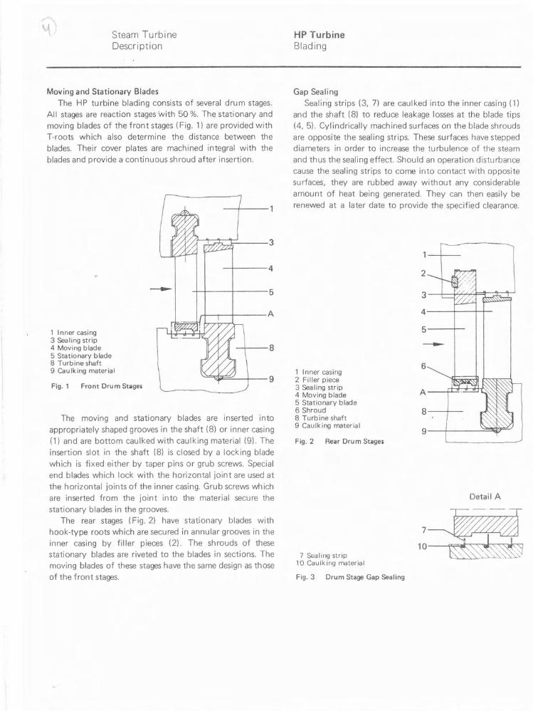
Moving and Stationary Blades The HP turbine blading consists of several drum stages.
All stages are reaction stages with 50 %. The stationary and moving blades of the front stages (Fig. 1) are provided with T-roots which also determine the distance between the blades. Their cover plates are machined integral with the blades and provide a continuous shroud after insertion.
~~' 3
I 4
I I I 5
A
1 Inner casing 3 Sealing strip 4 Moving blade
~I
.1 I I
I 8 5 Stationary blade 8 Turbine shaft 9 Caulking material
9 Fig. 1 Front Dru m Stages
The moving and stationary blades are inserted into appropriately shaped grooves in the shaft (8) or inner casing (1) and are bottom caulked with caulking material (9). The
insertion slot in the shaft (8) is closed by a locking blade which is fixed either by taper pins or grub screws. Special end blades which lock with the horizontal joint are used at the horizontal joints of the inner casing. Grub screws wh ich
are inserted from the joint into the material secure the stationary blades in the grooves.
The rear stages (Fig. 2) have stationary blades with hook-type roots which are secured in annular grooves in the inner casing by filler pieces (2). The shrouds of these stationary blades are riveted to the blades in sections. The moving blades of these stages have the same design as those of the front stages.
Gap Sealing Sealin'g strips (3. 7) are caulked into the inner casing (1)
and the shaft (8) to reduce leakage losses at the blade tips (4.5). Cylindrically machined surfaces on the blade shrouds
are opposite the sealing strips. These surfaces have stepped diameters in order to increase the turbulence of the steam and thus the sealing effect. Should an operation disturbance cause the sealing strips to come into contact with opposite surfaces, they are rubbed away without any considerable amount of heat being generated. They can then easily be renewed at a later date to provide the specified clearance.
2
1 Inner casing 2 Filler piece 3 Sealing strip 4 Moving blade 5 Stationary blade 6 Shroud 8 Turbine shaft 9 CaUlking material
Fig. 2 Rear Drum Stages
;~ 5 I
6
A JmBl 8 /
9 I ~
Detail A
7
7 Sealing strip 10 Caulking material
10
Fig. 3 Drum Stage Gap Sealing
J:~"
BHEL Hardwar 2-1120-00
~ Steam Turbine Combined Journal and Thrust Bearing Description
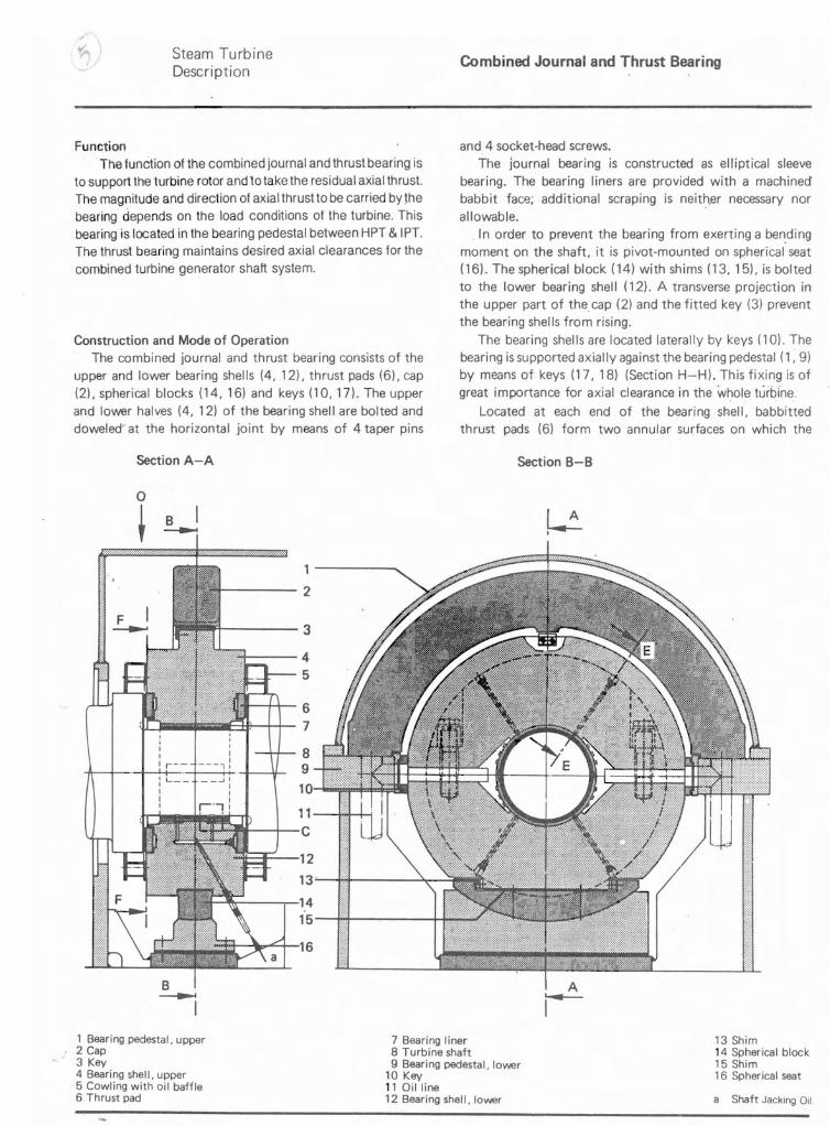
Function The function of the combined journal and thrust bearing is
to support the turbine rotor and to take the residual axial thrust. The magnitude and direction of axial thrust to be carried by ~he
bearing depends on the load conditions of the turbine. This bearing is located in the bearing pedestal between HPT & IPI. The thrust bearing maintains desired axial clearances for the combined turbine generator shaft system.
Construction and Mode of Operation The combined journal and thrust bearing consists of the
upper and lower bearing shells (4, 12), thrust pads (6), cap (2\. spherical blocks (14, 16) and keys (10, 17). The upper and lower halves (4, 12) of the bearing shell are bolted and doweled at the horizontal joint by means of 4 taper pins
Section A-A
B I ~
. t J I Ji '--- -- i \I r-.-, I
1
2
3
4 5
6 7
8 9 10
11 C
and 4 socket-head screws. The journal bearing is constructed as elliptical sleeve
bearing. The bearing liners are provided with a machined babbit face; additional scraping is neit~,er necessary nor allowable.
. In order to prevent the bearing from exerting a be~ding
moment on the shaft, it is pivot-mounted on spherical seat (16). The spherical block (14) with shims (13,15), is bolted to the lower bearing shell (12). A transverse projection in the upper part of the. cap (2) and the fitted key (3) prevent the bearing shells from rising.
The bearing shells are located laterally by keys (10). The bearing is supported axially against the bearing pedestal (1, 9) by means of keys (17, 18) (Section H-H). This fixing is of great importance for axial clearance in the whole turbine.
Located at each end of the bearing shell, babbitted thrust pads (6) form two annular surfaces on which the
Section B-B
~
[~1~~'12
13~~.: 111:'
16 Ii'!'
1 Bearing pedestal, upper 2 Cap 3 Key 4 Bearing shell, upper 5 Cowling with oil baffle
7 Bearing liner 8 Turbine shaft 9 Bearing pedestal, lovver
10 Key 11 Oil line
13 Shim 14 Spherical block 15 Shim 16 Spherical seat
6 Thrust pad 12 Bearing shell, lovver a Shaft Jacking Oil
BHEL Hardwar 2-1160-00/1
Steam Turbine IP Turbine Description Casing
--fA
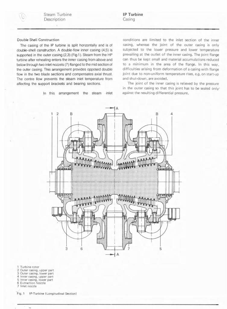
Double Shell Construction
The casing of the IP turbine .is split horizontally and is of double-shell constructon. A double-flow inner casing (4,5) is supported in the outer casing (2,3) (Fig.1 ). Steam from the HP turbine after reheating enters the inner casing from above and below through two inlet nozzels (7) flanged to the mid section of the outer casing. This arrangement provides opposed double flow in the two blade sections and compensates axial thrust. The centre flow prevents the steam inlet temperature from affecting the support brackets and bearing sections.
In this arrangement the steam .inlet
~A 2 B
3 6
, Turbi ne rotor 2 Outer casing, upper part 3 Outer casing, lower part 4 Inner casing, upper part 5 Inner casing, lower part 6 Extraction Nozzle 7 Inlet nozzle
Fig. 1 IP-Turbine (Longitudinal Section)
conditions are limited to the inlet section of the inner casing, whereas the joint of the outer casing is only subjected to the lower pressure and lower temperature prevailing at the outlet of the inner casing. The joint flange can thus be kept small and material accumulations reduced to a minimum in the area of the flange. In this way, difficulties arising from deformation of a casing with flange joint due to non-uniform temperature rises, e.g. on start-up and shut-down, are avoided.
The joint of the inner casing is relieved by the pressure in the outer casing so that this joint has to be sealed only' against the resulting differential pressure.
B 4
5
BHEL Hardwar 2-1210-00/1
--
Steam Turbine IP Turbine Description Blading
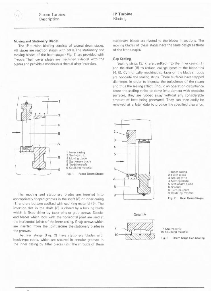
Moving and Stationary Blades The IP turbine blading consists of several drum stages.
All stages are reaction stages with 50 %.The stationary and moving blades of the front stages (Fig. 1) are provided. with T-roots Their cover plates are machined integral with the bl.ades and provide a continuous shroud after insertion.
~~I 3
I 4
I I I 5
.1 I --A
1 Inner casing 3 Sea ling strip
8 4 Moving blade 5 Stationary blade 8 Turbine shaft
\ 9 9 Caulking material "C. C/j Fig. 1 Front Drum Stages
The moving and stationary blades are inserted into appropriately shaped grooves in the shaft (8) or inner casing (1) and are bottom caulked with caulking material (9). The insertion slot in the shaft (8) is closed by a locking blade which is fixed either by taper pins or grub screws. Special end blades which lock with the horizontal joint are used at the horizontal joints of the inner casing. Gru~ screws which are inserted from the joint secure thelstationary blades in the grooves.
The rear stages (Fig. 2) have stationary blades with hook-type roots, which are secured in annular grooves in the inner casing by filler pieces (2). The shrouds of these
stationary blades are riveted to the blades in sections. The moving blades of these stages have the same design as those of the front stages.
Gap Sealing Sealing strips (3, 7) are caulked into the inner casing (1)
and the shaft (8) to reduce leakage losses at the blade tips (4, 5). Cylindrically machined surfaces on the blade shrouds are opposite the sealing strips. These surfaces have stepped diameters in order to increase the turbulence of the steam and thus the sealing effect. Should an operation disturbance cause the sealing strips to come into contact with opposite surfaces, they are rubbed away without any considerable amount of heat being generated. They can then easily be renewed at a later date to provide the specified clearanc€.
2
:~ 5 I
-6
1 Inner casing 2 Filler piece 3 Sealing stripA 4 Moving blade 5 Stationary blade
8 I
I j'"J'.±:::D ~"','\,~
6 Shroud 8 Turbine shaft
9 I \-")Wi>>> ·9 Caulking material
Fig. 2 Rear Drum Stages
Detail A
7 7 Sealing strip 10 Caulking material
Fig. 3 Drum Stage Gap Sealing
BHEL Hardwar 2-1220-00/1
Steam Turbine LP Turbine q., Description Casing
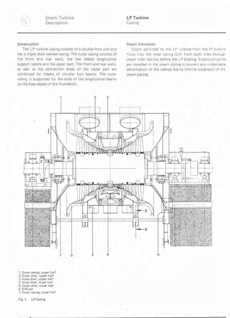
Construction
The LP turbine casing consists of a double-flow unit and has a triple shell welded casing. The outer casing consists of
the front and rear walls, the two lateral longitudinal support beams and the upper part. The front and rear walls, as well as the connection areas of the upper part are reinforced by means of circular box beams. The outer casing IS supported by the ends of the longitudinal beams on the base plates of the foundation.
2 3
Steam Admission
Steam admitted to the LP turbine from the IP turbine flows into the Inner ca'ilng (3;4) from both sides through
steam inlet nozzles before the LP Olading. Expansion Joints are installed in the steam piping to pr8vent any undesirable deformation of the casings due to thermal expansion of the
steam piping.
7 6 5 4 A
1 Outer casing, upper half 2 Outer shell, upper half 3 Inner shell, upper half 4 Inner shell, lower half 5 Outer shell, lower half 6 Diffuser 7 Outer casi ng, lower half
Fig. 1 LP Casing
BHEL Hardwar 2-1310-00/1
Steam Turbine LP Turbine Description LP Stages
•
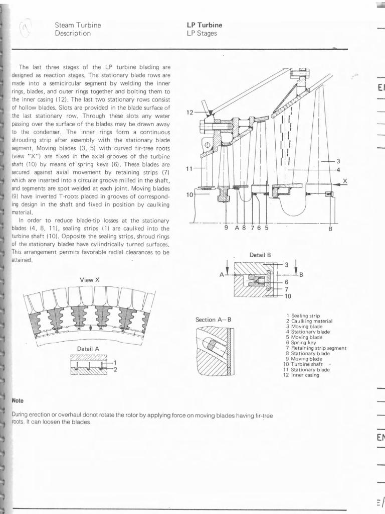
The last three stages of the LP turbine blading are designed as reaction stages. The stationary blade rows are
made into a semicircular segment by welding the inner rings, blades, and outer rings together and bolting them to
the inner casing (12). The last two stationarY rows consist
of hollow blades. Slots are provided in the blade surface of
the last stationary row. Through these slots any water passing over the surface of the blades may be drawn away to the condenser. The inner rings form a continuous shrouding strip after assembly with the stationary blade
segment. Moving blades (3, 5) with curved fir-tree roots
(view "X") are fixed in the axial grooves of the turbine shaft (10) by means of spring keys (6). These blades are secured against axial movement by retaining strips (7)
which are inserted into a circular groove milled in the shaft, and segments are spot welded at each joint. Moving blades (9) have inverted T -roots placed in grooves of corresponding design in the shaft and fixed in position by caulking material.
In order to reduce blade-tip losses at the stationary blades (4, 8, 11), sealing strips (1) are caulked into the turbine shaft (10). Opposite the sealing strips, shroud rings of the stationary blades have cylindrically turned surfaces. This arrangement permits favorable radial clearances to be attained.
View X
Detail A
Note
3 -t-·-t-+----;--4
12----.-• ./
Section A-B 2 Caulking material 3 Moving blade 4 Stationary blade 5 Moving blade 6 Spring key 7 Retaining strip segment 8 Stationary blade 9 Moving blade
10 Turbine shaft 11 Stationary blade 12 Inner casing
EMAR
11
10
9 A 8 7 6 5 B
Detail B
1 Sealing strip
During erection or overhaul donot rotate the rotor by applying force on moving blades having fir-tree roots. It can loosen the blades. .
EMA
BHfL Hardwar 2-1340-00 -
Inner casing Filler piece Sealing strip Moving blade Stationary blade Stationary blade Shaft seal Turbine shaft Caulking material
6 \ 1~0~
7
: r= J
~2~3 \ I A
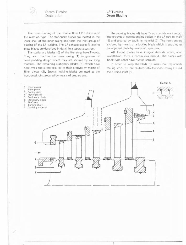
Steam Turbine LP Turbine Description Drum Blading
The drum blading of the double flow LP turbine is of the reaction type. The stationary blades are located in the inner shell of the 'inner casing and form the inlet group of blading of the LP turbine. The LP exhaust stages fol:owing these blades are described in detail in a separate section.
The stationary blades (6) of the first stage have T-roots. They are fitted in the inner casing (1) in grooves of corresponding design where they are secured by caulking material. The remaining stationary blades (5), which have hook-type roots, are secured in their grooves by means of filler pieces (2). Special locking blades are used at the horizontal joint, secured by means of grub screws.
1 2 3 4 5 6 7 8 9
The moving blades (4) have T-roots which are inserted into grooves of corresponding design in the LP turbine shaft (8) and secured by caulking material (9). The insertion slot is closed by means of a locking blade which is attached to the adjacent blade by means of taper pins.
All T-root blades have integral shrouds which, upon installation, form a continuous shroud. The blades with hook-type roots have riveted shrouds.
In order to keep the blad6! tip losses low, replaceable sealing strips (3) are caulked into the inner casing (1) and the turbine shaft (8).
Detail A
3~ ~.Y~'~~~~-,,' ........ -', "
. BHEL Hardwar 2-1330-00
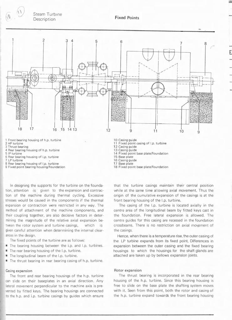
Steam Turbine Fixed Points Description
2 3 4 5 6 7 8
EMA
1', I ' I ' I I
- ---1
18 17 16 . .15 1413 12 9 11 10
1 Front bearing housing of h.p. turbine 2 HP turbine 3 Thrust bearing 4 Rear bearing housing of h.p. turbine 5 IP turbine 6 Rear bearing housing of i .p. turbine 7 LP turbine 8 Rear bearing housing of I.p. turbine 9 Fixed point bearing housing/foundation
In designing the supports for the turbine on the foundation, attention ,is given to the expansion and contraction of the machine during thermal cycling. Excessive stresses would be caused in the components if the thermal expansion or contraction vver.e restricted in any way. The method of attachment of the machine components, and their coupling together, are also decisive factors in determining the magnitude of the relative axial expansion bet't.€en the rotor system and turbine casings, which is given careful attention when determining the internal clearances in the design.
The fixed points of the turbine are as follows:
• The bearing housing between the i.p. and I.p. turbines.
• The rear bearing housing of the I.p. turbine. • The longitudinal beam of the I.p. turbine. • The thrust bearing in rear bearing casing of h.p. turbine.
Casing expansion The front and rear bearing housings of the h.p. turbine
can slide on their baseplates in an axial direction. Any lateral movement perpendicular to the machine axis is pre· vented by fitted keys. The bearing housings are connected to the h.p. and i.p. turbine casings by guides which ensure
9
10 Casing guide 11 Fixed point casing of I.p. turbine 12 Casing guide 13 Casing guide 14 Fixed point base plate/foundation 15 Base plate 16 Casing guide 17 Base plate 18 Fixed point base plate/foundation
that the turbine casings maintain their central positIOn while at the same time allowing axial movement. Thus the origin of the cumulative expansion of the casings is at the front bearing housing of the I.p. turbine.
The casing of the I.p. turbine is located axially in the centre area of the longitudinal beam by fitted keys cast in the foundation. Free lateral expansion is allowed. The centre guides for this casing are recessed in the foundation crossbeams. There is no restriction on axial mov..ement of the casings.
Hence. when there is a temperature rise, the outer casing of the LP turbine expands from its fixed point, Differences in expansion between the outer casing and the fixed bearing housings to which the housings for the shaft glands are attached are taken up by bellows expansion joints.
Rotor expansion ~MA The thrust bearing is incorporated in the rear bearing
housing of the h.p. turbine. Since this bearing housing is free to sl ide on the base plate the shafting system moves with it. Seen from this point, both the rotor and casing of the h.p. turbine expand towards the front bearing housing
BHEL Hardwar 2-0004-00/1 -'
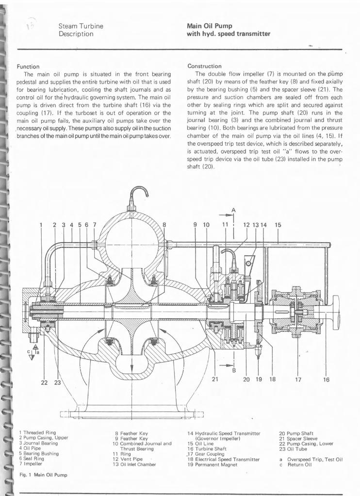
Steam Turbine Main Oil Pump Description with hyd. speed transmitter
Function The main oil pump is situated in the front bearing
pedestal and supplies the entire turbine with oil that is used for bearing lubrication, cooling the shaft journals and as control oil for the hydraulic governing system. The main oil pump is driven direct from the turbine shaft (16) via the coupling (17). If the turboset is out of operation or the main oil pump fails, the auxiliary oil pumps take over the
.necessary oil supply. These pumps also supply oil in the suction branches of the main oil pump until the main oil pump takes over.
Construction The double flow impeller (7) is mounted on the pump
shaft (20) by means of the feather key (8) and fixed axially by the bearing bushing (5) and the spacer sleeve (21). The pressu re and suction chambers are sealed off from each other by sealing rings which are split and secured against turning at the joint. The pump shaft (20) runs in the journal bearing (3) and the combined journal and thrust bearing (10). Both bearings are lubricated from the pressure
chamber of the main oil pump via the oil lines (4, 15). If the overspeed trip test device, which is described separately, is actuated, overspeed trip test oil "a" flows to the overspeed trip device via the oil tube (23) installed in the pump shaft (20).
16171820 19
, --I
B
21
r·-·fT-Lf-.....L------+-------:>.-p--r+·--,L._ '_J
22
1 Threaded Ring 2 Pump Casing, Upper 3 Journal Bearing 4 Oil Pipe 5 Bearing Bushing 6 Seal Ring 7 Impeller
Fig. 1 Main Oil Pump
8 Feather Key 9 Feather Key
10 Combined Journal and Thrust Bearing
11 Ring 12 Vent Pipe 13 Oil Inlet Chamber
14 Hydraulic Speed Transmitter (Governor Impeller)
15 Oil Line 16 Turbine Shaft J 7 Gear Coupling 18 Electrical Speed Transmitter 19 Permanent Magnet
20 Pump Shaft 21 Spacer Sleeve 22 Pump Casing, Lower 23 Oil Tube
a Overspeed Trip, Test Oil c Return Oil
'BHEL Hardwar 2-4310-00/1
..
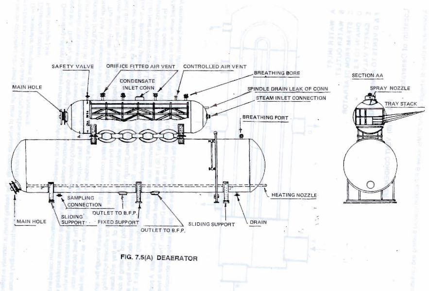
SAFETY VA LV E OR I FICE FITTED A IR V ENT CONTROL LED AI R V ENT BREATH ING BOR E SECTION AA
CONDENSA TE
SPRAY NOZZLE ~'NO:E DRAIN LEAK OF CONN
~ STEAM IN L ET CONNECT ION
~THINGPORT
CD N
'OUTLET TO B.F .P.
' MA IN HOLE . F I XED SUPPORT . , -_. - - --- SLI DING SUPPORT OUT LET TO B.F.P .
FIG. 7.5(A) DEAERATOR